JP6572063B2 - All-solid-state secondary battery, electrode sheet for all-solid-state secondary battery, and production method thereof - Google Patents
All-solid-state secondary battery, electrode sheet for all-solid-state secondary battery, and production method thereof Download PDFInfo
- Publication number
- JP6572063B2 JP6572063B2 JP2015166955A JP2015166955A JP6572063B2 JP 6572063 B2 JP6572063 B2 JP 6572063B2 JP 2015166955 A JP2015166955 A JP 2015166955A JP 2015166955 A JP2015166955 A JP 2015166955A JP 6572063 B2 JP6572063 B2 JP 6572063B2
- Authority
- JP
- Japan
- Prior art keywords
- solvent
- content
- active material
- layer
- electrode active
- Prior art date
- Legal status (The legal status is an assumption and is not a legal conclusion. Google has not performed a legal analysis and makes no representation as to the accuracy of the status listed.)
- Active
Links
- 238000004519 manufacturing process Methods 0.000 title claims description 23
- 239000007784 solid electrolyte Substances 0.000 claims description 163
- 239000002904 solvent Substances 0.000 claims description 124
- 229910052751 metal Inorganic materials 0.000 claims description 118
- 239000002184 metal Substances 0.000 claims description 118
- 239000000203 mixture Substances 0.000 claims description 87
- 238000009835 boiling Methods 0.000 claims description 83
- 239000007774 positive electrode material Substances 0.000 claims description 83
- 239000007773 negative electrode material Substances 0.000 claims description 82
- 239000007787 solid Substances 0.000 claims description 70
- 150000003839 salts Chemical class 0.000 claims description 62
- 239000011888 foil Substances 0.000 claims description 47
- 229910003480 inorganic solid Inorganic materials 0.000 claims description 47
- 150000002500 ions Chemical class 0.000 claims description 34
- 230000000737 periodic effect Effects 0.000 claims description 27
- 238000001035 drying Methods 0.000 claims description 20
- 239000011248 coating agent Substances 0.000 claims description 11
- 238000000576 coating method Methods 0.000 claims description 11
- 229910021645 metal ion Inorganic materials 0.000 claims description 10
- 150000002739 metals Chemical class 0.000 claims description 8
- 239000010410 layer Substances 0.000 description 315
- 239000002245 particle Substances 0.000 description 63
- 235000002639 sodium chloride Nutrition 0.000 description 46
- IMNFDUFMRHMDMM-UHFFFAOYSA-N N-Heptane Chemical compound CCCCCCC IMNFDUFMRHMDMM-UHFFFAOYSA-N 0.000 description 34
- 239000000126 substance Substances 0.000 description 25
- -1 LiBrO 4 Inorganic materials 0.000 description 21
- HBBGRARXTFLTSG-UHFFFAOYSA-N Lithium ion Chemical compound [Li+] HBBGRARXTFLTSG-UHFFFAOYSA-N 0.000 description 20
- 229910001416 lithium ion Inorganic materials 0.000 description 20
- 229910052782 aluminium Inorganic materials 0.000 description 19
- 229910052744 lithium Inorganic materials 0.000 description 19
- 238000005259 measurement Methods 0.000 description 18
- OKTJSMMVPCPJKN-UHFFFAOYSA-N Carbon Chemical compound [C] OKTJSMMVPCPJKN-UHFFFAOYSA-N 0.000 description 16
- WHXSMMKQMYFTQS-UHFFFAOYSA-N Lithium Chemical compound [Li] WHXSMMKQMYFTQS-UHFFFAOYSA-N 0.000 description 16
- MCMNRKCIXSYSNV-UHFFFAOYSA-N Zirconium dioxide Chemical compound O=[Zr]=O MCMNRKCIXSYSNV-UHFFFAOYSA-N 0.000 description 16
- 239000011230 binding agent Substances 0.000 description 15
- 238000000034 method Methods 0.000 description 15
- PXHVJJICTQNCMI-UHFFFAOYSA-N nickel Substances [Ni] PXHVJJICTQNCMI-UHFFFAOYSA-N 0.000 description 13
- 239000000243 solution Substances 0.000 description 13
- OKKJLVBELUTLKV-UHFFFAOYSA-N Methanol Chemical compound OC OKKJLVBELUTLKV-UHFFFAOYSA-N 0.000 description 12
- 239000003792 electrolyte Substances 0.000 description 12
- 229920000642 polymer Polymers 0.000 description 12
- 239000010936 titanium Substances 0.000 description 12
- 125000004432 carbon atom Chemical group C* 0.000 description 11
- IEJIGPNLZYLLBP-UHFFFAOYSA-N dimethyl carbonate Chemical compound COC(=O)OC IEJIGPNLZYLLBP-UHFFFAOYSA-N 0.000 description 11
- 229920000193 polymethacrylate Polymers 0.000 description 11
- 238000002360 preparation method Methods 0.000 description 11
- 229910052719 titanium Inorganic materials 0.000 description 11
- UCKMPCXJQFINFW-UHFFFAOYSA-N Sulphide Chemical compound [S-2] UCKMPCXJQFINFW-UHFFFAOYSA-N 0.000 description 10
- 239000003575 carbonaceous material Substances 0.000 description 10
- 239000000463 material Substances 0.000 description 10
- RUOJZAUFBMNUDX-UHFFFAOYSA-N propylene carbonate Chemical compound CC1COC(=O)O1 RUOJZAUFBMNUDX-UHFFFAOYSA-N 0.000 description 10
- 238000012360 testing method Methods 0.000 description 10
- CSCPPACGZOOCGX-UHFFFAOYSA-N Acetone Chemical compound CC(C)=O CSCPPACGZOOCGX-UHFFFAOYSA-N 0.000 description 9
- 239000004793 Polystyrene Substances 0.000 description 9
- 125000000217 alkyl group Chemical group 0.000 description 9
- XAGFODPZIPBFFR-UHFFFAOYSA-N aluminium Chemical compound [Al] XAGFODPZIPBFFR-UHFFFAOYSA-N 0.000 description 9
- JFDZBHWFFUWGJE-UHFFFAOYSA-N benzonitrile Chemical compound N#CC1=CC=CC=C1 JFDZBHWFFUWGJE-UHFFFAOYSA-N 0.000 description 9
- 229910018091 Li 2 S Inorganic materials 0.000 description 8
- 229920002396 Polyurea Polymers 0.000 description 8
- 239000002612 dispersion medium Substances 0.000 description 8
- 238000011156 evaluation Methods 0.000 description 8
- 229910052731 fluorine Inorganic materials 0.000 description 8
- 229910052733 gallium Inorganic materials 0.000 description 8
- 239000011521 glass Substances 0.000 description 8
- 238000010438 heat treatment Methods 0.000 description 8
- 229910003473 lithium bis(trifluoromethanesulfonyl)imide Inorganic materials 0.000 description 8
- 229910052759 nickel Inorganic materials 0.000 description 8
- 229910052710 silicon Inorganic materials 0.000 description 8
- 229910052717 sulfur Inorganic materials 0.000 description 8
- 229910052718 tin Inorganic materials 0.000 description 8
- 229920000049 Carbon (fiber) Polymers 0.000 description 7
- 229910052799 carbon Inorganic materials 0.000 description 7
- 239000004917 carbon fiber Substances 0.000 description 7
- 150000001875 compounds Chemical class 0.000 description 7
- 229910052802 copper Inorganic materials 0.000 description 7
- 239000010949 copper Substances 0.000 description 7
- 239000002270 dispersing agent Substances 0.000 description 7
- 230000006870 function Effects 0.000 description 7
- 229910052732 germanium Inorganic materials 0.000 description 7
- QSZMZKBZAYQGRS-UHFFFAOYSA-N lithium;bis(trifluoromethylsulfonyl)azanide Chemical compound [Li+].FC(F)(F)S(=O)(=O)[N-]S(=O)(=O)C(F)(F)F QSZMZKBZAYQGRS-UHFFFAOYSA-N 0.000 description 7
- 229910052698 phosphorus Inorganic materials 0.000 description 7
- 229920005989 resin Polymers 0.000 description 7
- 239000011347 resin Substances 0.000 description 7
- 239000002002 slurry Substances 0.000 description 7
- 229910000314 transition metal oxide Inorganic materials 0.000 description 7
- IJGRMHOSHXDMSA-UHFFFAOYSA-N Atomic nitrogen Chemical compound N#N IJGRMHOSHXDMSA-UHFFFAOYSA-N 0.000 description 6
- 229910018130 Li 2 S-P 2 S 5 Inorganic materials 0.000 description 6
- YXFVVABEGXRONW-UHFFFAOYSA-N Toluene Chemical compound CC1=CC=CC=C1 YXFVVABEGXRONW-UHFFFAOYSA-N 0.000 description 6
- 239000011149 active material Substances 0.000 description 6
- 229910052796 boron Inorganic materials 0.000 description 6
- 239000006185 dispersion Substances 0.000 description 6
- 229910002804 graphite Inorganic materials 0.000 description 6
- 239000010439 graphite Substances 0.000 description 6
- VNWKTOKETHGBQD-UHFFFAOYSA-N methane Chemical compound C VNWKTOKETHGBQD-UHFFFAOYSA-N 0.000 description 6
- VYPSYNLAJGMNEJ-UHFFFAOYSA-N silicon dioxide Inorganic materials O=[Si]=O VYPSYNLAJGMNEJ-UHFFFAOYSA-N 0.000 description 6
- RYGMFSIKBFXOCR-UHFFFAOYSA-N Copper Chemical compound [Cu] RYGMFSIKBFXOCR-UHFFFAOYSA-N 0.000 description 5
- WYURNTSHIVDZCO-UHFFFAOYSA-N Tetrahydrofuran Chemical compound C1CCOC1 WYURNTSHIVDZCO-UHFFFAOYSA-N 0.000 description 5
- RTAQQCXQSZGOHL-UHFFFAOYSA-N Titanium Chemical compound [Ti] RTAQQCXQSZGOHL-UHFFFAOYSA-N 0.000 description 5
- 125000003118 aryl group Chemical group 0.000 description 5
- 238000006243 chemical reaction Methods 0.000 description 5
- 229920001577 copolymer Polymers 0.000 description 5
- 229910052740 iodine Inorganic materials 0.000 description 5
- GLNWILHOFOBOFD-UHFFFAOYSA-N lithium sulfide Chemical compound [Li+].[Li+].[S-2] GLNWILHOFOBOFD-UHFFFAOYSA-N 0.000 description 5
- 239000000178 monomer Substances 0.000 description 5
- 239000005486 organic electrolyte Substances 0.000 description 5
- 229920002981 polyvinylidene fluoride Polymers 0.000 description 5
- 239000010935 stainless steel Substances 0.000 description 5
- 229910001220 stainless steel Inorganic materials 0.000 description 5
- 229910052720 vanadium Inorganic materials 0.000 description 5
- YEJRWHAVMIAJKC-UHFFFAOYSA-N 4-Butyrolactone Chemical compound O=C1CCCO1 YEJRWHAVMIAJKC-UHFFFAOYSA-N 0.000 description 4
- 229920000178 Acrylic resin Polymers 0.000 description 4
- 239000004925 Acrylic resin Substances 0.000 description 4
- HEDRZPFGACZZDS-UHFFFAOYSA-N Chloroform Chemical compound ClC(Cl)Cl HEDRZPFGACZZDS-UHFFFAOYSA-N 0.000 description 4
- RTZKZFJDLAIYFH-UHFFFAOYSA-N Diethyl ether Chemical compound CCOCC RTZKZFJDLAIYFH-UHFFFAOYSA-N 0.000 description 4
- LYCAIKOWRPUZTN-UHFFFAOYSA-N Ethylene glycol Chemical compound OCCO LYCAIKOWRPUZTN-UHFFFAOYSA-N 0.000 description 4
- 229910013063 LiBF 4 Inorganic materials 0.000 description 4
- 229910013684 LiClO 4 Inorganic materials 0.000 description 4
- 229910013870 LiPF 6 Inorganic materials 0.000 description 4
- SECXISVLQFMRJM-UHFFFAOYSA-N N-Methylpyrrolidone Chemical compound CN1CCCC1=O SECXISVLQFMRJM-UHFFFAOYSA-N 0.000 description 4
- 239000002033 PVDF binder Substances 0.000 description 4
- OFBQJSOFQDEBGM-UHFFFAOYSA-N Pentane Chemical compound CCCCC OFBQJSOFQDEBGM-UHFFFAOYSA-N 0.000 description 4
- NINIDFKCEFEMDL-UHFFFAOYSA-N Sulfur Chemical compound [S] NINIDFKCEFEMDL-UHFFFAOYSA-N 0.000 description 4
- 239000007877 V-601 Substances 0.000 description 4
- 229910052787 antimony Inorganic materials 0.000 description 4
- 239000011324 bead Substances 0.000 description 4
- 230000015572 biosynthetic process Effects 0.000 description 4
- 229910052794 bromium Inorganic materials 0.000 description 4
- 150000004770 chalcogenides Chemical class 0.000 description 4
- 229910052801 chlorine Inorganic materials 0.000 description 4
- 239000013078 crystal Substances 0.000 description 4
- 239000008151 electrolyte solution Substances 0.000 description 4
- 125000001153 fluoro group Chemical group F* 0.000 description 4
- GAEKPEKOJKCEMS-UHFFFAOYSA-N gamma-valerolactone Chemical compound CC1CCC(=O)O1 GAEKPEKOJKCEMS-UHFFFAOYSA-N 0.000 description 4
- 239000007789 gas Substances 0.000 description 4
- 239000002241 glass-ceramic Substances 0.000 description 4
- 125000004435 hydrogen atom Chemical group [H]* 0.000 description 4
- 229910052738 indium Inorganic materials 0.000 description 4
- 239000007788 liquid Substances 0.000 description 4
- 238000002156 mixing Methods 0.000 description 4
- 229910052758 niobium Inorganic materials 0.000 description 4
- 239000003960 organic solvent Substances 0.000 description 4
- 229910052760 oxygen Inorganic materials 0.000 description 4
- CYQAYERJWZKYML-UHFFFAOYSA-N phosphorus pentasulfide Chemical compound S1P(S2)(=S)SP3(=S)SP1(=S)SP2(=S)S3 CYQAYERJWZKYML-UHFFFAOYSA-N 0.000 description 4
- 239000002994 raw material Substances 0.000 description 4
- 125000001424 substituent group Chemical group 0.000 description 4
- 238000003786 synthesis reaction Methods 0.000 description 4
- ZUHZGEOKBKGPSW-UHFFFAOYSA-N tetraglyme Chemical compound COCCOCCOCCOCCOC ZUHZGEOKBKGPSW-UHFFFAOYSA-N 0.000 description 4
- 229920002803 thermoplastic polyurethane Polymers 0.000 description 4
- XLYOFNOQVPJJNP-UHFFFAOYSA-N water Substances O XLYOFNOQVPJJNP-UHFFFAOYSA-N 0.000 description 4
- ZWEHNKRNPOVVGH-UHFFFAOYSA-N 2-Butanone Chemical compound CCC(C)=O ZWEHNKRNPOVVGH-UHFFFAOYSA-N 0.000 description 3
- SBLRHMKNNHXPHG-UHFFFAOYSA-N 4-fluoro-1,3-dioxolan-2-one Chemical compound FC1COC(=O)O1 SBLRHMKNNHXPHG-UHFFFAOYSA-N 0.000 description 3
- WEVYAHXRMPXWCK-UHFFFAOYSA-N Acetonitrile Chemical compound CC#N WEVYAHXRMPXWCK-UHFFFAOYSA-N 0.000 description 3
- UHOVQNZJYSORNB-UHFFFAOYSA-N Benzene Chemical compound C1=CC=CC=C1 UHOVQNZJYSORNB-UHFFFAOYSA-N 0.000 description 3
- XEKOWRVHYACXOJ-UHFFFAOYSA-N Ethyl acetate Chemical compound CCOC(C)=O XEKOWRVHYACXOJ-UHFFFAOYSA-N 0.000 description 3
- ZMXDDKWLCZADIW-UHFFFAOYSA-N N,N-Dimethylformamide Chemical compound CN(C)C=O ZMXDDKWLCZADIW-UHFFFAOYSA-N 0.000 description 3
- ZMANZCXQSJIPKH-UHFFFAOYSA-N Triethylamine Chemical group CCN(CC)CC ZMANZCXQSJIPKH-UHFFFAOYSA-N 0.000 description 3
- RJEIKIOYHOOKDL-UHFFFAOYSA-N [Li].[La] Chemical compound [Li].[La] RJEIKIOYHOOKDL-UHFFFAOYSA-N 0.000 description 3
- 239000006230 acetylene black Substances 0.000 description 3
- NIXOWILDQLNWCW-UHFFFAOYSA-N acrylic acid group Chemical group C(C=C)(=O)O NIXOWILDQLNWCW-UHFFFAOYSA-N 0.000 description 3
- 125000003342 alkenyl group Chemical group 0.000 description 3
- 229910021383 artificial graphite Inorganic materials 0.000 description 3
- BTANRVKWQNVYAZ-UHFFFAOYSA-N butan-2-ol Chemical compound CCC(C)O BTANRVKWQNVYAZ-UHFFFAOYSA-N 0.000 description 3
- 239000000460 chlorine Substances 0.000 description 3
- 239000002131 composite material Substances 0.000 description 3
- 239000004020 conductor Substances 0.000 description 3
- 125000004093 cyano group Chemical group *C#N 0.000 description 3
- MTHSVFCYNBDYFN-UHFFFAOYSA-N diethylene glycol Chemical compound OCCOCCO MTHSVFCYNBDYFN-UHFFFAOYSA-N 0.000 description 3
- 238000007599 discharging Methods 0.000 description 3
- 238000009826 distribution Methods 0.000 description 3
- 239000007772 electrode material Substances 0.000 description 3
- 238000011049 filling Methods 0.000 description 3
- 125000000524 functional group Chemical group 0.000 description 3
- 229910052742 iron Inorganic materials 0.000 description 3
- XEEYBQQBJWHFJM-UHFFFAOYSA-N iron Substances [Fe] XEEYBQQBJWHFJM-UHFFFAOYSA-N 0.000 description 3
- 229910052748 manganese Inorganic materials 0.000 description 3
- 239000011572 manganese Substances 0.000 description 3
- 238000003701 mechanical milling Methods 0.000 description 3
- 239000002905 metal composite material Substances 0.000 description 3
- 229910044991 metal oxide Inorganic materials 0.000 description 3
- 150000004706 metal oxides Chemical class 0.000 description 3
- VLKZOEOYAKHREP-UHFFFAOYSA-N n-Hexane Chemical compound CCCCCC VLKZOEOYAKHREP-UHFFFAOYSA-N 0.000 description 3
- 229910021382 natural graphite Inorganic materials 0.000 description 3
- 229910052757 nitrogen Inorganic materials 0.000 description 3
- 229920000620 organic polymer Polymers 0.000 description 3
- 238000003860 storage Methods 0.000 description 3
- 239000011593 sulfur Substances 0.000 description 3
- 229910052723 transition metal Inorganic materials 0.000 description 3
- SVONRAPFKPVNKG-UHFFFAOYSA-N 2-ethoxyethyl acetate Chemical compound CCOCCOC(C)=O SVONRAPFKPVNKG-UHFFFAOYSA-N 0.000 description 2
- 229910000838 Al alloy Inorganic materials 0.000 description 2
- IAZDPXIOMUYVGZ-UHFFFAOYSA-N Dimethylsulphoxide Chemical compound CS(C)=O IAZDPXIOMUYVGZ-UHFFFAOYSA-N 0.000 description 2
- LFQSCWFLJHTTHZ-UHFFFAOYSA-N Ethanol Chemical compound CCO LFQSCWFLJHTTHZ-UHFFFAOYSA-N 0.000 description 2
- JOYRKODLDBILNP-UHFFFAOYSA-N Ethyl urethane Chemical compound CCOC(N)=O JOYRKODLDBILNP-UHFFFAOYSA-N 0.000 description 2
- KMTRUDSVKNLOMY-UHFFFAOYSA-N Ethylene carbonate Chemical compound O=C1OCCO1 KMTRUDSVKNLOMY-UHFFFAOYSA-N 0.000 description 2
- 239000002227 LISICON Substances 0.000 description 2
- 229910018133 Li 2 S-SiS 2 Inorganic materials 0.000 description 2
- 229910009293 Li2S-GeS2-Ga2S3 Inorganic materials 0.000 description 2
- 229910009290 Li2S-GeS2-P2S5 Inorganic materials 0.000 description 2
- 229910009324 Li2S-SiS2-Li3PO4 Inorganic materials 0.000 description 2
- 229910009326 Li2S-SiS2-Li4SiO4 Inorganic materials 0.000 description 2
- 229910009331 Li2S-SiS2-P2S5 Inorganic materials 0.000 description 2
- 229910009328 Li2S-SiS2—Li3PO4 Inorganic materials 0.000 description 2
- 229910009108 Li2S—GeS2—Ga2S3 Inorganic materials 0.000 description 2
- 229910009110 Li2S—GeS2—P2S5 Inorganic materials 0.000 description 2
- 229910009148 Li2S—Li2O—P2S5 Inorganic materials 0.000 description 2
- 229910009142 Li2S—Li3PO4—P2S5 Inorganic materials 0.000 description 2
- 229910009145 Li2S—LiI—Li2O—P2S5 Inorganic materials 0.000 description 2
- 229910007295 Li2S—SiS2—Li3PO4 Inorganic materials 0.000 description 2
- 229910007290 Li2S—SiS2—Li4SiO4 Inorganic materials 0.000 description 2
- 229910007298 Li2S—SiS2—P2S5 Inorganic materials 0.000 description 2
- 229910012851 LiCoO 2 Inorganic materials 0.000 description 2
- BAPJBEWLBFYGME-UHFFFAOYSA-N Methyl acrylate Chemical compound COC(=O)C=C BAPJBEWLBFYGME-UHFFFAOYSA-N 0.000 description 2
- VVQNEPGJFQJSBK-UHFFFAOYSA-N Methyl methacrylate Chemical compound COC(=O)C(C)=C VVQNEPGJFQJSBK-UHFFFAOYSA-N 0.000 description 2
- OAICVXFJPJFONN-UHFFFAOYSA-N Phosphorus Chemical compound [P] OAICVXFJPJFONN-UHFFFAOYSA-N 0.000 description 2
- 239000004372 Polyvinyl alcohol Substances 0.000 description 2
- VKCLPVFDVVKEKU-UHFFFAOYSA-N S=[P] Chemical compound S=[P] VKCLPVFDVVKEKU-UHFFFAOYSA-N 0.000 description 2
- 229910006404 SnO 2 Inorganic materials 0.000 description 2
- FAPWRFPIFSIZLT-UHFFFAOYSA-M Sodium chloride Chemical group [Na+].[Cl-] FAPWRFPIFSIZLT-UHFFFAOYSA-M 0.000 description 2
- 239000002253 acid Substances 0.000 description 2
- 230000002378 acidificating effect Effects 0.000 description 2
- BTGRAWJCKBQKAO-UHFFFAOYSA-N adiponitrile Chemical compound N#CCCCCC#N BTGRAWJCKBQKAO-UHFFFAOYSA-N 0.000 description 2
- 238000004220 aggregation Methods 0.000 description 2
- 230000002776 aggregation Effects 0.000 description 2
- 238000005280 amorphization Methods 0.000 description 2
- 150000001450 anions Chemical class 0.000 description 2
- 239000007864 aqueous solution Substances 0.000 description 2
- 239000012300 argon atmosphere Substances 0.000 description 2
- 229910052785 arsenic Inorganic materials 0.000 description 2
- 239000012298 atmosphere Substances 0.000 description 2
- QVGXLLKOCUKJST-UHFFFAOYSA-N atomic oxygen Chemical compound [O] QVGXLLKOCUKJST-UHFFFAOYSA-N 0.000 description 2
- 239000001273 butane Substances 0.000 description 2
- WERYXYBDKMZEQL-UHFFFAOYSA-N butane-1,4-diol Chemical compound OCCCCO WERYXYBDKMZEQL-UHFFFAOYSA-N 0.000 description 2
- CQEYYJKEWSMYFG-UHFFFAOYSA-N butyl acrylate Chemical compound CCCCOC(=O)C=C CQEYYJKEWSMYFG-UHFFFAOYSA-N 0.000 description 2
- NMJJFJNHVMGPGM-UHFFFAOYSA-N butyl formate Chemical compound CCCCOC=O NMJJFJNHVMGPGM-UHFFFAOYSA-N 0.000 description 2
- 229910052791 calcium Inorganic materials 0.000 description 2
- 239000006229 carbon black Substances 0.000 description 2
- 235000019241 carbon black Nutrition 0.000 description 2
- 239000002134 carbon nanofiber Substances 0.000 description 2
- 150000001768 cations Chemical class 0.000 description 2
- 239000003795 chemical substances by application Substances 0.000 description 2
- 229910052804 chromium Inorganic materials 0.000 description 2
- 239000011651 chromium Substances 0.000 description 2
- 238000007796 conventional method Methods 0.000 description 2
- 238000001816 cooling Methods 0.000 description 2
- JHIVVAPYMSGYDF-UHFFFAOYSA-N cyclohexanone Chemical compound O=C1CCCCC1 JHIVVAPYMSGYDF-UHFFFAOYSA-N 0.000 description 2
- 229910001873 dinitrogen Inorganic materials 0.000 description 2
- 125000003438 dodecyl group Chemical group [H]C([H])([H])C([H])([H])C([H])([H])C([H])([H])C([H])([H])C([H])([H])C([H])([H])C([H])([H])C([H])([H])C([H])([H])C([H])([H])C([H])([H])* 0.000 description 2
- 238000002296 dynamic light scattering Methods 0.000 description 2
- 239000000839 emulsion Substances 0.000 description 2
- 239000000835 fiber Substances 0.000 description 2
- 239000010419 fine particle Substances 0.000 description 2
- 230000009477 glass transition Effects 0.000 description 2
- ZTOMUSMDRMJOTH-UHFFFAOYSA-N glutaronitrile Chemical compound N#CCCCC#N ZTOMUSMDRMJOTH-UHFFFAOYSA-N 0.000 description 2
- 229910052737 gold Inorganic materials 0.000 description 2
- 229910021389 graphene Inorganic materials 0.000 description 2
- HCDGVLDPFQMKDK-UHFFFAOYSA-N hexafluoropropylene Chemical group FC(F)=C(F)C(F)(F)F HCDGVLDPFQMKDK-UHFFFAOYSA-N 0.000 description 2
- 150000002430 hydrocarbons Chemical class 0.000 description 2
- 230000006872 improvement Effects 0.000 description 2
- 238000009413 insulation Methods 0.000 description 2
- KWGKDLIKAYFUFQ-UHFFFAOYSA-M lithium chloride Chemical compound [Li+].[Cl-] KWGKDLIKAYFUFQ-UHFFFAOYSA-M 0.000 description 2
- 229910001386 lithium phosphate Inorganic materials 0.000 description 2
- RLSSMJSEOOYNOY-UHFFFAOYSA-N m-cresol Chemical compound CC1=CC=CC(O)=C1 RLSSMJSEOOYNOY-UHFFFAOYSA-N 0.000 description 2
- 229910052749 magnesium Inorganic materials 0.000 description 2
- 229910052750 molybdenum Inorganic materials 0.000 description 2
- 239000004570 mortar (masonry) Substances 0.000 description 2
- IJDNQMDRQITEOD-UHFFFAOYSA-N n-butane Chemical compound CCCC IJDNQMDRQITEOD-UHFFFAOYSA-N 0.000 description 2
- 239000001301 oxygen Substances 0.000 description 2
- 125000005010 perfluoroalkyl group Chemical group 0.000 description 2
- 150000003013 phosphoric acid derivatives Chemical class 0.000 description 2
- 239000011574 phosphorus Substances 0.000 description 2
- 229910052697 platinum Inorganic materials 0.000 description 2
- 229920000196 poly(lauryl methacrylate) Polymers 0.000 description 2
- 229920002239 polyacrylonitrile Polymers 0.000 description 2
- 229920001195 polyisoprene Polymers 0.000 description 2
- 229920002223 polystyrene Polymers 0.000 description 2
- 229920001343 polytetrafluoroethylene Polymers 0.000 description 2
- 239000004810 polytetrafluoroethylene Substances 0.000 description 2
- 229920002635 polyurethane Polymers 0.000 description 2
- 239000004814 polyurethane Substances 0.000 description 2
- 229920002451 polyvinyl alcohol Polymers 0.000 description 2
- 239000000843 powder Substances 0.000 description 2
- 239000000047 product Substances 0.000 description 2
- BDERNNFJNOPAEC-UHFFFAOYSA-N propan-1-ol Chemical compound CCCO BDERNNFJNOPAEC-UHFFFAOYSA-N 0.000 description 2
- 238000010298 pulverizing process Methods 0.000 description 2
- 239000010453 quartz Substances 0.000 description 2
- 238000010992 reflux Methods 0.000 description 2
- 229910052707 ruthenium Inorganic materials 0.000 description 2
- 239000011343 solid material Substances 0.000 description 2
- 125000006850 spacer group Chemical group 0.000 description 2
- 239000011029 spinel Substances 0.000 description 2
- 229910052596 spinel Inorganic materials 0.000 description 2
- 238000003756 stirring Methods 0.000 description 2
- 229910052712 strontium Inorganic materials 0.000 description 2
- 229920003048 styrene butadiene rubber Polymers 0.000 description 2
- 239000002203 sulfidic glass Substances 0.000 description 2
- 229910052715 tantalum Inorganic materials 0.000 description 2
- YLQBMQCUIZJEEH-UHFFFAOYSA-N tetrahydrofuran Natural products C=1C=COC=1 YLQBMQCUIZJEEH-UHFFFAOYSA-N 0.000 description 2
- 229910000319 transition metal phosphate Inorganic materials 0.000 description 2
- 229910000326 transition metal silicate Inorganic materials 0.000 description 2
- TWQULNDIKKJZPH-UHFFFAOYSA-K trilithium;phosphate Chemical compound [Li+].[Li+].[Li+].[O-]P([O-])([O-])=O TWQULNDIKKJZPH-UHFFFAOYSA-K 0.000 description 2
- 229910052721 tungsten Inorganic materials 0.000 description 2
- 229910052726 zirconium Inorganic materials 0.000 description 2
- RYHBNJHYFVUHQT-UHFFFAOYSA-N 1,4-Dioxane Chemical compound C1COCCO1 RYHBNJHYFVUHQT-UHFFFAOYSA-N 0.000 description 1
- DURPTKYDGMDSBL-UHFFFAOYSA-N 1-butoxybutane Chemical compound CCCCOCCCC DURPTKYDGMDSBL-UHFFFAOYSA-N 0.000 description 1
- SMZOUWXMTYCWNB-UHFFFAOYSA-N 2-(2-methoxy-5-methylphenyl)ethanamine Chemical compound COC1=CC=C(C)C=C1CCN SMZOUWXMTYCWNB-UHFFFAOYSA-N 0.000 description 1
- XNWFRZJHXBZDAG-UHFFFAOYSA-N 2-METHOXYETHANOL Chemical compound COCCO XNWFRZJHXBZDAG-UHFFFAOYSA-N 0.000 description 1
- VNAWKNVDKFZFSU-UHFFFAOYSA-N 2-ethyl-2-methylpropane-1,3-diol Chemical compound CCC(C)(CO)CO VNAWKNVDKFZFSU-UHFFFAOYSA-N 0.000 description 1
- 125000000954 2-hydroxyethyl group Chemical group [H]C([*])([H])C([H])([H])O[H] 0.000 description 1
- MHRDCHHESNJQIS-UHFFFAOYSA-N 2-methyl-3-sulfanylpropanoic acid Chemical compound SCC(C)C(O)=O MHRDCHHESNJQIS-UHFFFAOYSA-N 0.000 description 1
- VSGKEWJNJIONGY-UHFFFAOYSA-N 2-methylprop-2-enenitrile;prop-2-enoic acid Chemical compound CC(=C)C#N.OC(=O)C=C VSGKEWJNJIONGY-UHFFFAOYSA-N 0.000 description 1
- RNLHGQLZWXBQNY-UHFFFAOYSA-N 3-(aminomethyl)-3,5,5-trimethylcyclohexan-1-amine Chemical compound CC1(C)CC(N)CC(C)(CN)C1 RNLHGQLZWXBQNY-UHFFFAOYSA-N 0.000 description 1
- OOWFYDWAMOKVSF-UHFFFAOYSA-N 3-methoxypropanenitrile Chemical compound COCCC#N OOWFYDWAMOKVSF-UHFFFAOYSA-N 0.000 description 1
- ZCYVEMRRCGMTRW-UHFFFAOYSA-N 7553-56-2 Chemical group [I] ZCYVEMRRCGMTRW-UHFFFAOYSA-N 0.000 description 1
- HRPVXLWXLXDGHG-UHFFFAOYSA-N Acrylamide Chemical group NC(=O)C=C HRPVXLWXLXDGHG-UHFFFAOYSA-N 0.000 description 1
- 208000023514 Barrett esophagus Diseases 0.000 description 1
- 229910015902 Bi 2 O 3 Inorganic materials 0.000 description 1
- WKBOTKDWSSQWDR-UHFFFAOYSA-N Bromine atom Chemical group [Br] WKBOTKDWSSQWDR-UHFFFAOYSA-N 0.000 description 1
- DKPFZGUDAPQIHT-UHFFFAOYSA-N Butyl acetate Natural products CCCCOC(C)=O DKPFZGUDAPQIHT-UHFFFAOYSA-N 0.000 description 1
- FERIUCNNQQJTOY-UHFFFAOYSA-M Butyrate Chemical compound CCCC([O-])=O FERIUCNNQQJTOY-UHFFFAOYSA-M 0.000 description 1
- XHVXBDMHJKOQQE-UHFFFAOYSA-N C(C=C)(=O)O.C=CC1=CC=CC=C1.C(CCC)C(C#N)=C Chemical compound C(C=C)(=O)O.C=CC1=CC=CC=C1.C(CCC)C(C#N)=C XHVXBDMHJKOQQE-UHFFFAOYSA-N 0.000 description 1
- XMWRBQBLMFGWIX-UHFFFAOYSA-N C60 fullerene Chemical compound C12=C3C(C4=C56)=C7C8=C5C5=C9C%10=C6C6=C4C1=C1C4=C6C6=C%10C%10=C9C9=C%11C5=C8C5=C8C7=C3C3=C7C2=C1C1=C2C4=C6C4=C%10C6=C9C9=C%11C5=C5C8=C3C3=C7C1=C1C2=C4C6=C2C9=C5C3=C12 XMWRBQBLMFGWIX-UHFFFAOYSA-N 0.000 description 1
- 239000004215 Carbon black (E152) Substances 0.000 description 1
- 229920000298 Cellophane Polymers 0.000 description 1
- 229920008712 Copo Polymers 0.000 description 1
- 229910000881 Cu alloy Inorganic materials 0.000 description 1
- XDTMQSROBMDMFD-UHFFFAOYSA-N Cyclohexane Chemical compound C1CCCCC1 XDTMQSROBMDMFD-UHFFFAOYSA-N 0.000 description 1
- OIFBSDVPJOWBCH-UHFFFAOYSA-N Diethyl carbonate Chemical compound CCOC(=O)OCC OIFBSDVPJOWBCH-UHFFFAOYSA-N 0.000 description 1
- ZAFNJMIOTHYJRJ-UHFFFAOYSA-N Diisopropyl ether Chemical compound CC(C)OC(C)C ZAFNJMIOTHYJRJ-UHFFFAOYSA-N 0.000 description 1
- SNRUBQQJIBEYMU-UHFFFAOYSA-N Dodecane Natural products CCCCCCCCCCCC SNRUBQQJIBEYMU-UHFFFAOYSA-N 0.000 description 1
- JIGUQPWFLRLWPJ-UHFFFAOYSA-N Ethyl acrylate Chemical compound CCOC(=O)C=C JIGUQPWFLRLWPJ-UHFFFAOYSA-N 0.000 description 1
- 229910015136 FeMn Inorganic materials 0.000 description 1
- YCKRFDGAMUMZLT-UHFFFAOYSA-N Fluorine atom Chemical compound [F] YCKRFDGAMUMZLT-UHFFFAOYSA-N 0.000 description 1
- 229910005191 Ga 2 O 3 Inorganic materials 0.000 description 1
- 239000005058 Isophorone diisocyanate Substances 0.000 description 1
- KFZMGEQAYNKOFK-UHFFFAOYSA-N Isopropanol Chemical compound CC(C)O KFZMGEQAYNKOFK-UHFFFAOYSA-N 0.000 description 1
- 229910019271 La0.55Li0.35TiO3 Inorganic materials 0.000 description 1
- 229910018092 Li 2 S-Al 2 S 3 Inorganic materials 0.000 description 1
- 229910018127 Li 2 S-GeS 2 Inorganic materials 0.000 description 1
- 229910018119 Li 3 PO 4 Inorganic materials 0.000 description 1
- 229910000733 Li alloy Inorganic materials 0.000 description 1
- 229910004499 Li(Ni1/3Mn1/3Co1/3)O2 Inorganic materials 0.000 description 1
- 229910020722 Li0.33La0.55TiO3 Inorganic materials 0.000 description 1
- 229910008745 Li2O-B2O3-P2O5 Inorganic materials 0.000 description 1
- 229910008590 Li2O—B2O3—P2O5 Inorganic materials 0.000 description 1
- 229910009318 Li2S-SiS2-LiI Inorganic materials 0.000 description 1
- 229910009353 Li2S—GeS2—Al2S3 Inorganic materials 0.000 description 1
- 229910009102 Li2S—GeS2—Sb2S5 Inorganic materials 0.000 description 1
- 229910009130 Li2S—GeS2—ZnS Inorganic materials 0.000 description 1
- 229910009181 Li2S—LiI—P2S5 Inorganic materials 0.000 description 1
- 229910007289 Li2S—SiS2—LiI Inorganic materials 0.000 description 1
- 229910007306 Li2S—SiS2—P2S5LiI Inorganic materials 0.000 description 1
- 229910012329 Li3BO3—Li2SO4 Inorganic materials 0.000 description 1
- 229910012425 Li3Fe2 (PO4)3 Inorganic materials 0.000 description 1
- 229910010640 Li6BaLa2Ta2O12 Inorganic materials 0.000 description 1
- 229910015015 LiAsF 6 Inorganic materials 0.000 description 1
- 229910011281 LiCoPO 4 Inorganic materials 0.000 description 1
- 229910010941 LiFSI Inorganic materials 0.000 description 1
- 229910010701 LiFeP Inorganic materials 0.000 description 1
- 229910010707 LiFePO 4 Inorganic materials 0.000 description 1
- 229910013131 LiN Inorganic materials 0.000 description 1
- 229910013716 LiNi Inorganic materials 0.000 description 1
- 229910013825 LiNi0.33Co0.33Mn0.33O2 Inorganic materials 0.000 description 1
- 229910012752 LiNi0.5Mn0.5O2 Inorganic materials 0.000 description 1
- 229910015701 LiNi0.85Co0.10Al0.05O2 Inorganic materials 0.000 description 1
- 229910012305 LiPON Inorganic materials 0.000 description 1
- 229910012513 LiSbF 6 Inorganic materials 0.000 description 1
- 229910012465 LiTi Inorganic materials 0.000 description 1
- NTIZESTWPVYFNL-UHFFFAOYSA-N Methyl isobutyl ketone Chemical compound CC(C)CC(C)=O NTIZESTWPVYFNL-UHFFFAOYSA-N 0.000 description 1
- UIHCLUNTQKBZGK-UHFFFAOYSA-N Methyl isobutyl ketone Natural products CCC(C)C(C)=O UIHCLUNTQKBZGK-UHFFFAOYSA-N 0.000 description 1
- 229910003289 NiMn Inorganic materials 0.000 description 1
- 229920000459 Nitrile rubber Polymers 0.000 description 1
- 240000007320 Pinus strobus Species 0.000 description 1
- 229920002845 Poly(methacrylic acid) Polymers 0.000 description 1
- 239000005062 Polybutadiene Substances 0.000 description 1
- 239000004698 Polyethylene Substances 0.000 description 1
- 229920000265 Polyparaphenylene Polymers 0.000 description 1
- 239000004743 Polypropylene Substances 0.000 description 1
- XBDQKXXYIPTUBI-UHFFFAOYSA-M Propionate Chemical compound CCC([O-])=O XBDQKXXYIPTUBI-UHFFFAOYSA-M 0.000 description 1
- 229910004298 SiO 2 Inorganic materials 0.000 description 1
- 229910020346 SiS 2 Inorganic materials 0.000 description 1
- BQCADISMDOOEFD-UHFFFAOYSA-N Silver Chemical compound [Ag] BQCADISMDOOEFD-UHFFFAOYSA-N 0.000 description 1
- 229910005790 SnSiO Inorganic materials 0.000 description 1
- KEAYESYHFKHZAL-UHFFFAOYSA-N Sodium Chemical compound [Na] KEAYESYHFKHZAL-UHFFFAOYSA-N 0.000 description 1
- QYTDEUPAUMOIOP-UHFFFAOYSA-N TEMPO Chemical group CC1(C)CCCC(C)(C)N1[O] QYTDEUPAUMOIOP-UHFFFAOYSA-N 0.000 description 1
- XSQUKJJJFZCRTK-UHFFFAOYSA-N Urea Chemical compound NC(N)=O XSQUKJJJFZCRTK-UHFFFAOYSA-N 0.000 description 1
- 238000002441 X-ray diffraction Methods 0.000 description 1
- NFOVOLLZYFKJCK-UHFFFAOYSA-J [Fe+4].[O-]P([O-])(=O)OP([O-])([O-])=O Chemical class [Fe+4].[O-]P([O-])(=O)OP([O-])([O-])=O NFOVOLLZYFKJCK-UHFFFAOYSA-J 0.000 description 1
- YWJVFBOUPMWANA-UHFFFAOYSA-H [Li+].[V+5].[O-]P([O-])([O-])=O.[O-]P([O-])([O-])=O Chemical compound [Li+].[V+5].[O-]P([O-])([O-])=O.[O-]P([O-])([O-])=O YWJVFBOUPMWANA-UHFFFAOYSA-H 0.000 description 1
- JFBZPFYRPYOZCQ-UHFFFAOYSA-N [Li].[Al] Chemical compound [Li].[Al] JFBZPFYRPYOZCQ-UHFFFAOYSA-N 0.000 description 1
- KLARSDUHONHPRF-UHFFFAOYSA-N [Li].[Mn] Chemical compound [Li].[Mn] KLARSDUHONHPRF-UHFFFAOYSA-N 0.000 description 1
- GLMOMDXKLRBTDY-UHFFFAOYSA-A [V+5].[V+5].[V+5].[O-]P([O-])([O-])=O.[O-]P([O-])([O-])=O.[O-]P([O-])([O-])=O.[O-]P([O-])([O-])=O.[O-]P([O-])([O-])=O Chemical class [V+5].[V+5].[V+5].[O-]P([O-])([O-])=O.[O-]P([O-])([O-])=O.[O-]P([O-])([O-])=O.[O-]P([O-])([O-])=O.[O-]P([O-])([O-])=O GLMOMDXKLRBTDY-UHFFFAOYSA-A 0.000 description 1
- KXBFLNPZHXDQLV-UHFFFAOYSA-N [cyclohexyl(diisocyanato)methyl]cyclohexane Chemical compound C1CCCCC1C(N=C=O)(N=C=O)C1CCCCC1 KXBFLNPZHXDQLV-UHFFFAOYSA-N 0.000 description 1
- 150000001298 alcohols Chemical class 0.000 description 1
- 150000007824 aliphatic compounds Chemical class 0.000 description 1
- 125000005370 alkoxysilyl group Chemical group 0.000 description 1
- 229910045601 alloy Inorganic materials 0.000 description 1
- 239000000956 alloy Substances 0.000 description 1
- HSFWRNGVRCDJHI-UHFFFAOYSA-N alpha-acetylene Natural products C#C HSFWRNGVRCDJHI-UHFFFAOYSA-N 0.000 description 1
- NDPGDHBNXZOBJS-UHFFFAOYSA-N aluminum lithium cobalt(2+) nickel(2+) oxygen(2-) Chemical compound [Li+].[O--].[O--].[O--].[O--].[Al+3].[Co++].[Ni++] NDPGDHBNXZOBJS-UHFFFAOYSA-N 0.000 description 1
- 229910003481 amorphous carbon Inorganic materials 0.000 description 1
- 150000001491 aromatic compounds Chemical class 0.000 description 1
- 125000004429 atom Chemical group 0.000 description 1
- GCTPMLUUWLLESL-UHFFFAOYSA-N benzyl prop-2-enoate Chemical compound C=CC(=O)OCC1=CC=CC=C1 GCTPMLUUWLLESL-UHFFFAOYSA-N 0.000 description 1
- 229910052797 bismuth Inorganic materials 0.000 description 1
- MTAZNLWOLGHBHU-UHFFFAOYSA-N butadiene-styrene rubber Chemical class C=CC=C.C=CC1=CC=CC=C1 MTAZNLWOLGHBHU-UHFFFAOYSA-N 0.000 description 1
- 239000004202 carbamide Substances 0.000 description 1
- 239000002041 carbon nanotube Substances 0.000 description 1
- 229910021393 carbon nanotube Inorganic materials 0.000 description 1
- 239000003660 carbonate based solvent Substances 0.000 description 1
- 150000004649 carbonic acid derivatives Chemical class 0.000 description 1
- 229920002678 cellulose Polymers 0.000 description 1
- 239000001913 cellulose Substances 0.000 description 1
- 230000008859 change Effects 0.000 description 1
- 239000007795 chemical reaction product Substances 0.000 description 1
- 125000001309 chloro group Chemical group Cl* 0.000 description 1
- 239000011247 coating layer Substances 0.000 description 1
- FHCPLZDXSWLYHT-UHFFFAOYSA-L cobalt(2+) fluoro-dioxido-oxo-lambda5-phosphane Chemical class [Co+2].[O-]P([O-])(F)=O FHCPLZDXSWLYHT-UHFFFAOYSA-L 0.000 description 1
- 239000000084 colloidal system Substances 0.000 description 1
- 230000000052 comparative effect Effects 0.000 description 1
- 239000002482 conductive additive Substances 0.000 description 1
- 229920001940 conductive polymer Polymers 0.000 description 1
- 239000000470 constituent Substances 0.000 description 1
- 239000011889 copper foil Substances 0.000 description 1
- 238000001514 detection method Methods 0.000 description 1
- 230000006866 deterioration Effects 0.000 description 1
- 238000003618 dip coating Methods 0.000 description 1
- 238000004090 dissolution Methods 0.000 description 1
- GMSCBRSQMRDRCD-UHFFFAOYSA-N dodecyl 2-methylprop-2-enoate Chemical compound CCCCCCCCCCCCOC(=O)C(C)=C GMSCBRSQMRDRCD-UHFFFAOYSA-N 0.000 description 1
- 230000000694 effects Effects 0.000 description 1
- 229920001971 elastomer Polymers 0.000 description 1
- 239000003480 eluent Substances 0.000 description 1
- 125000003700 epoxy group Chemical group 0.000 description 1
- 235000019441 ethanol Nutrition 0.000 description 1
- 150000002170 ethers Chemical class 0.000 description 1
- JBTWLSYIZRCDFO-UHFFFAOYSA-N ethyl methyl carbonate Chemical compound CCOC(=O)OC JBTWLSYIZRCDFO-UHFFFAOYSA-N 0.000 description 1
- 230000003203 everyday effect Effects 0.000 description 1
- 230000001747 exhibiting effect Effects 0.000 description 1
- 238000010304 firing Methods 0.000 description 1
- 150000004673 fluoride salts Chemical class 0.000 description 1
- 239000011737 fluorine Substances 0.000 description 1
- 239000006260 foam Substances 0.000 description 1
- WBJINCZRORDGAQ-UHFFFAOYSA-N formic acid ethyl ester Natural products CCOC=O WBJINCZRORDGAQ-UHFFFAOYSA-N 0.000 description 1
- 238000009472 formulation Methods 0.000 description 1
- 229910003472 fullerene Inorganic materials 0.000 description 1
- XPFVYQJUAUNWIW-UHFFFAOYSA-N furfuryl alcohol Chemical compound OCC1=CC=CO1 XPFVYQJUAUNWIW-UHFFFAOYSA-N 0.000 description 1
- 239000006232 furnace black Substances 0.000 description 1
- 239000011245 gel electrolyte Substances 0.000 description 1
- 239000011809 glassy carbon fiber Substances 0.000 description 1
- 125000003055 glycidyl group Chemical group C(C1CO1)* 0.000 description 1
- VOZRXNHHFUQHIL-UHFFFAOYSA-N glycidyl methacrylate Chemical compound CC(=C)C(=O)OCC1CO1 VOZRXNHHFUQHIL-UHFFFAOYSA-N 0.000 description 1
- 238000005087 graphitization Methods 0.000 description 1
- 125000005843 halogen group Chemical group 0.000 description 1
- FUZZWVXGSFPDMH-UHFFFAOYSA-M hexanoate Chemical compound CCCCCC([O-])=O FUZZWVXGSFPDMH-UHFFFAOYSA-M 0.000 description 1
- LNMQRPPRQDGUDR-UHFFFAOYSA-N hexyl prop-2-enoate Chemical compound CCCCCCOC(=O)C=C LNMQRPPRQDGUDR-UHFFFAOYSA-N 0.000 description 1
- 229930195733 hydrocarbon Natural products 0.000 description 1
- 125000004356 hydroxy functional group Chemical group O* 0.000 description 1
- WGCNASOHLSPBMP-UHFFFAOYSA-N hydroxyacetaldehyde Natural products OCC=O WGCNASOHLSPBMP-UHFFFAOYSA-N 0.000 description 1
- 229910001506 inorganic fluoride Inorganic materials 0.000 description 1
- WBJZTOZJJYAKHQ-UHFFFAOYSA-K iron(3+) phosphate Chemical class [Fe+3].[O-]P([O-])([O-])=O WBJZTOZJJYAKHQ-UHFFFAOYSA-K 0.000 description 1
- 125000000959 isobutyl group Chemical group [H]C([H])([H])C([H])(C([H])([H])[H])C([H])([H])* 0.000 description 1
- IQPQWNKOIGAROB-UHFFFAOYSA-N isocyanate group Chemical group [N-]=C=O IQPQWNKOIGAROB-UHFFFAOYSA-N 0.000 description 1
- NIMLQBUJDJZYEJ-UHFFFAOYSA-N isophorone diisocyanate Chemical compound CC1(C)CC(N=C=O)CC(C)(CN=C=O)C1 NIMLQBUJDJZYEJ-UHFFFAOYSA-N 0.000 description 1
- 125000001449 isopropyl group Chemical group [H]C([H])([H])C([H])(*)C([H])([H])[H] 0.000 description 1
- 239000003273 ketjen black Substances 0.000 description 1
- 239000004816 latex Substances 0.000 description 1
- 229920000126 latex Polymers 0.000 description 1
- 229920005610 lignin Polymers 0.000 description 1
- 239000001989 lithium alloy Substances 0.000 description 1
- FUJCRWPEOMXPAD-UHFFFAOYSA-N lithium oxide Chemical compound [Li+].[Li+].[O-2] FUJCRWPEOMXPAD-UHFFFAOYSA-N 0.000 description 1
- 229910001947 lithium oxide Inorganic materials 0.000 description 1
- 229910003002 lithium salt Inorganic materials 0.000 description 1
- 159000000002 lithium salts Chemical class 0.000 description 1
- VDVLPSWVDYJFRW-UHFFFAOYSA-N lithium;bis(fluorosulfonyl)azanide Chemical compound [Li+].FS(=O)(=O)[N-]S(F)(=O)=O VDVLPSWVDYJFRW-UHFFFAOYSA-N 0.000 description 1
- VGYDTVNNDKLMHX-UHFFFAOYSA-N lithium;manganese;nickel;oxocobalt Chemical compound [Li].[Mn].[Ni].[Co]=O VGYDTVNNDKLMHX-UHFFFAOYSA-N 0.000 description 1
- 230000007774 longterm Effects 0.000 description 1
- WPBNNNQJVZRUHP-UHFFFAOYSA-L manganese(2+);methyl n-[[2-(methoxycarbonylcarbamothioylamino)phenyl]carbamothioyl]carbamate;n-[2-(sulfidocarbothioylamino)ethyl]carbamodithioate Chemical compound [Mn+2].[S-]C(=S)NCCNC([S-])=S.COC(=O)NC(=S)NC1=CC=CC=C1NC(=S)NC(=O)OC WPBNNNQJVZRUHP-UHFFFAOYSA-L 0.000 description 1
- 238000000691 measurement method Methods 0.000 description 1
- 238000007578 melt-quenching technique Methods 0.000 description 1
- 239000005300 metallic glass Substances 0.000 description 1
- 125000005641 methacryl group Chemical group 0.000 description 1
- 239000004005 microsphere Substances 0.000 description 1
- 239000011259 mixed solution Substances 0.000 description 1
- YKYONYBAUNKHLG-UHFFFAOYSA-N n-Propyl acetate Natural products CCCOC(C)=O YKYONYBAUNKHLG-UHFFFAOYSA-N 0.000 description 1
- 239000011331 needle coke Substances 0.000 description 1
- 125000004433 nitrogen atom Chemical group N* 0.000 description 1
- 229910021470 non-graphitizable carbon Inorganic materials 0.000 description 1
- TVMXDCGIABBOFY-UHFFFAOYSA-N octane Chemical compound CCCCCCCC TVMXDCGIABBOFY-UHFFFAOYSA-N 0.000 description 1
- 125000002347 octyl group Chemical group [H]C([*])([H])C([H])([H])C([H])([H])C([H])([H])C([H])([H])C([H])([H])C([H])([H])C([H])([H])[H] 0.000 description 1
- 125000003566 oxetanyl group Chemical group 0.000 description 1
- PNJWIWWMYCMZRO-UHFFFAOYSA-N pent‐4‐en‐2‐one Natural products CC(=O)CC=C PNJWIWWMYCMZRO-UHFFFAOYSA-N 0.000 description 1
- 239000011301 petroleum pitch Substances 0.000 description 1
- DPTATFGPDCLUTF-UHFFFAOYSA-N phosphanylidyneiron Chemical class [Fe]#P DPTATFGPDCLUTF-UHFFFAOYSA-N 0.000 description 1
- 150000003018 phosphorus compounds Chemical class 0.000 description 1
- 239000011295 pitch Substances 0.000 description 1
- 239000000088 plastic resin Substances 0.000 description 1
- 229920001197 polyacetylene Polymers 0.000 description 1
- 229920006350 polyacrylonitrile resin Polymers 0.000 description 1
- 229920000767 polyaniline Polymers 0.000 description 1
- 229920002857 polybutadiene Polymers 0.000 description 1
- 229920000573 polyethylene Polymers 0.000 description 1
- 239000005518 polymer electrolyte Substances 0.000 description 1
- 239000002861 polymer material Substances 0.000 description 1
- 229920005862 polyol Polymers 0.000 description 1
- 150000003077 polyols Chemical class 0.000 description 1
- 229920001155 polypropylene Polymers 0.000 description 1
- 229920000128 polypyrrole Polymers 0.000 description 1
- 229920000123 polythiophene Polymers 0.000 description 1
- 229910052700 potassium Inorganic materials 0.000 description 1
- 239000002244 precipitate Substances 0.000 description 1
- 238000001556 precipitation Methods 0.000 description 1
- 125000002924 primary amino group Chemical group [H]N([H])* 0.000 description 1
- 238000012545 processing Methods 0.000 description 1
- 229940090181 propyl acetate Drugs 0.000 description 1
- 238000012827 research and development Methods 0.000 description 1
- 230000004044 response Effects 0.000 description 1
- 230000000717 retained effect Effects 0.000 description 1
- 239000005060 rubber Substances 0.000 description 1
- 239000004576 sand Substances 0.000 description 1
- 150000004760 silicates Chemical class 0.000 description 1
- LIVNPJMFVYWSIS-UHFFFAOYSA-N silicon monoxide Chemical compound [Si-]#[O+] LIVNPJMFVYWSIS-UHFFFAOYSA-N 0.000 description 1
- 229910052814 silicon oxide Inorganic materials 0.000 description 1
- 229910052709 silver Inorganic materials 0.000 description 1
- 239000004332 silver Substances 0.000 description 1
- 229910052708 sodium Inorganic materials 0.000 description 1
- 239000011734 sodium Substances 0.000 description 1
- 229910001415 sodium ion Inorganic materials 0.000 description 1
- 238000004528 spin coating Methods 0.000 description 1
- 238000005507 spraying Methods 0.000 description 1
- 125000004079 stearyl group Chemical group [H]C([*])([H])C([H])([H])C([H])([H])C([H])([H])C([H])([H])C([H])([H])C([H])([H])C([H])([H])C([H])([H])C([H])([H])C([H])([H])C([H])([H])C([H])([H])C([H])([H])C([H])([H])C([H])([H])C([H])([H])C([H])([H])[H] 0.000 description 1
- HXJUTPCZVOIRIF-UHFFFAOYSA-N sulfolane Chemical compound O=S1(=O)CCCC1 HXJUTPCZVOIRIF-UHFFFAOYSA-N 0.000 description 1
- 239000002226 superionic conductor Substances 0.000 description 1
- 238000004381 surface treatment Methods 0.000 description 1
- 239000000725 suspension Substances 0.000 description 1
- 230000002194 synthesizing effect Effects 0.000 description 1
- 229920003002 synthetic resin Polymers 0.000 description 1
- 239000000057 synthetic resin Substances 0.000 description 1
- JRMUNVKIHCOMHV-UHFFFAOYSA-M tetrabutylammonium bromide Chemical compound [Br-].CCCC[N+](CCCC)(CCCC)CCCC JRMUNVKIHCOMHV-UHFFFAOYSA-M 0.000 description 1
- 125000000383 tetramethylene group Chemical group [H]C([H])([*:1])C([H])([H])C([H])([H])C([H])([H])[*:2] 0.000 description 1
- 125000003396 thiol group Chemical group [H]S* 0.000 description 1
- XOLBLPGZBRYERU-UHFFFAOYSA-N tin dioxide Chemical compound O=[Sn]=O XOLBLPGZBRYERU-UHFFFAOYSA-N 0.000 description 1
- 229910001887 tin oxide Inorganic materials 0.000 description 1
- 150000003624 transition metals Chemical class 0.000 description 1
- WVLBCYQITXONBZ-UHFFFAOYSA-N trimethyl phosphate Chemical compound COP(=O)(OC)OC WVLBCYQITXONBZ-UHFFFAOYSA-N 0.000 description 1
- NQPDZGIKBAWPEJ-UHFFFAOYSA-N valeric acid Chemical compound CCCCC(O)=O NQPDZGIKBAWPEJ-UHFFFAOYSA-N 0.000 description 1
- 125000000391 vinyl group Chemical group [H]C([*])=C([H])[H] 0.000 description 1
- 229920002554 vinyl polymer Polymers 0.000 description 1
- 239000011800 void material Substances 0.000 description 1
- 229910052725 zinc Inorganic materials 0.000 description 1
Images
Classifications
-
- Y—GENERAL TAGGING OF NEW TECHNOLOGICAL DEVELOPMENTS; GENERAL TAGGING OF CROSS-SECTIONAL TECHNOLOGIES SPANNING OVER SEVERAL SECTIONS OF THE IPC; TECHNICAL SUBJECTS COVERED BY FORMER USPC CROSS-REFERENCE ART COLLECTIONS [XRACs] AND DIGESTS
- Y02—TECHNOLOGIES OR APPLICATIONS FOR MITIGATION OR ADAPTATION AGAINST CLIMATE CHANGE
- Y02E—REDUCTION OF GREENHOUSE GAS [GHG] EMISSIONS, RELATED TO ENERGY GENERATION, TRANSMISSION OR DISTRIBUTION
- Y02E60/00—Enabling technologies; Technologies with a potential or indirect contribution to GHG emissions mitigation
- Y02E60/10—Energy storage using batteries
-
- Y—GENERAL TAGGING OF NEW TECHNOLOGICAL DEVELOPMENTS; GENERAL TAGGING OF CROSS-SECTIONAL TECHNOLOGIES SPANNING OVER SEVERAL SECTIONS OF THE IPC; TECHNICAL SUBJECTS COVERED BY FORMER USPC CROSS-REFERENCE ART COLLECTIONS [XRACs] AND DIGESTS
- Y02—TECHNOLOGIES OR APPLICATIONS FOR MITIGATION OR ADAPTATION AGAINST CLIMATE CHANGE
- Y02P—CLIMATE CHANGE MITIGATION TECHNOLOGIES IN THE PRODUCTION OR PROCESSING OF GOODS
- Y02P70/00—Climate change mitigation technologies in the production process for final industrial or consumer products
- Y02P70/50—Manufacturing or production processes characterised by the final manufactured product
Landscapes
- Inorganic Compounds Of Heavy Metals (AREA)
- Battery Electrode And Active Subsutance (AREA)
- Conductive Materials (AREA)
- Secondary Cells (AREA)
Description
本発明は、全固体二次電池およびその製造方法に関する。また本発明は、全固体二次電池用電極シート及びその製造方法に関する。 The present invention relates to an all-solid secondary battery and a method for manufacturing the same. Moreover, this invention relates to the electrode sheet for all-solid-state secondary batteries, and its manufacturing method.
リチウムイオン二次電池は、負極と、正極と、負極と正極との間に挟まれた電解質とを有し、両極間にリチウムイオンを往復移動させることにより充電、放電を可能とした蓄電池である。リチウムイオン二次電池には従来から、電解質として有機電解液が用いられてきた。しかし有機電解液は液漏れを生じやすく、また、過充電、過放電により電池内部で短絡が生じ発火するおそれもあり、信頼性と安全性のさらなる向上が求められている。
かかる要求を満たすべく、電解液にポリマーを配合し、ポリマー中に有機電解液を保持させることが知られている。例えば特許文献1には、ポリビニリデンフルオライド等の高分子材料とヘキサフルオロプロピレンとリチウムイオン電導性ガラスセラミックスをアセトンに投入した懸濁液を用いてシートを調製し、このシートを、エチレンカーボネート、ジメチルカーボネート等の有機溶媒に浸漬し、ゲル状物からなるシート状の複合電解質を作成したことが記載され、この複合電解質を用いることにより、電池容量が高く、充放電サイクル特性も良好で、長期安定使用が可能なリチウム二次電池を得たことが記載されている。
A lithium ion secondary battery is a storage battery that has a negative electrode, a positive electrode, and an electrolyte sandwiched between the negative electrode and the positive electrode, and can be charged and discharged by reciprocating lithium ions between the two electrodes. . Conventionally, an organic electrolytic solution has been used as an electrolyte in a lithium ion secondary battery. However, organic electrolytes are liable to leak, and overcharge and overdischarge can cause a short circuit inside the battery, resulting in fire, and further improvements in reliability and safety are required.
In order to satisfy such a requirement, it is known that a polymer is blended in an electrolytic solution and an organic electrolytic solution is retained in the polymer. For example, in Patent Document 1, a sheet is prepared using a suspension in which a polymer material such as polyvinylidene fluoride, hexafluoropropylene, and lithium ion conductive glass ceramics are added to acetone. It is described that a sheet-like composite electrolyte made of a gel-like material was created by immersing in an organic solvent such as dimethyl carbonate. By using this composite electrolyte, the battery capacity is high, the charge / discharge cycle characteristics are also good, and the long-term It is described that a lithium secondary battery that can be used stably is obtained.
しかし、上記特許文献1記載のゲル状電解質においても、カーボネート系溶媒などの可燃性の材料が用いられており、過充電時などに不具合を来たすおそれがないとは言えず、さらなる安全性の向上が望まれている。
かかる状況下、可燃性の有機電解液に代えて、不燃性の無機固体電解質を用いた全固体二次電池が注目されている。全固体二次電池は負極、電解質、正極のすべてが固体からなり、有機電解液を用いた電池の課題とされる安全性ないし信頼性を大きく改善することができ、また長寿命化も可能になるとされる。
さらに全固体二次電池では、電極と電解質を直接並べて直列に配した構造とすることができ、これにより電池セルを封止する金属パッケージ、電池セルをつなぐ銅線やバスバーを省略することができる。それ故、有機電解液を用いた二次電池に比べて高エネルギー密度化が可能となり、電気自動車や大型蓄電池等への応用が期待されている。
However, even in the gel electrolyte described in Patent Document 1, a flammable material such as a carbonate-based solvent is used, and it cannot be said that there is no possibility of causing a problem at the time of overcharge, and further improvement in safety. Is desired.
Under such circumstances, an all-solid secondary battery using a non-flammable inorganic solid electrolyte instead of a flammable organic electrolyte has attracted attention. The all-solid-state secondary battery consists of a solid negative electrode, electrolyte, and positive electrode, which can greatly improve safety and reliability, which is a problem of batteries using organic electrolytes, and can extend the service life. It will be.
Furthermore, in an all-solid-state secondary battery, an electrode and an electrolyte can be directly arranged in series, so that a metal package that seals the battery cell, a copper wire that connects the battery cell, and a bus bar can be omitted. . Therefore, the energy density can be increased as compared with a secondary battery using an organic electrolyte, and application to an electric vehicle, a large storage battery, and the like is expected.
全固体二次電池は次世代二次電池として大きな期待が寄せられているが、その実用化に向けた研究開発は始まったばかりであり、正極、負極、電解質等の構成と電池性能との関係には未だ不明な点が多い。
本発明は、固体電解質粒子間の結着性に優れ、内部抵抗(界面抵抗)が低減されて優れたイオン伝導性を示す全固体二次電池、全固体二次電池用電極シート及びこれらの製造方法を提供することを課題とする。
Although all-solid-state secondary batteries are highly expected as next-generation secondary batteries, research and development for their practical use has just begun, and the relationship between the configuration of positive electrodes, negative electrodes, electrolytes, etc., and battery performance There are still many unclear points.
The present invention provides an all-solid secondary battery, an all-solid-state secondary battery electrode sheet having excellent binding properties between solid electrolyte particles, reduced internal resistance (interface resistance), and excellent ion conductivity, and production thereof. It is an object to provide a method.
全固体二次電池には、電解質としてイオン伝導性の無機固体電解質が用いられる。この無機固体電解質は微粒子であるため、密にパッキングしても電解質粒子間にはある程度の空隙が生じる。本発明者らは、かかる電解質粒子間の微小な空隙がイオン伝導性向上の制約になっているとの着想の下、電解質粒子間の空隙を効果的に塞いで内部抵抗を低減し、イオン伝導性を高めるべく鋭意検討を重ねた。
その結果、固体電解質に対し、特定の金属塩と、微量の高沸点溶媒とを共存させることにより、高沸点溶媒と金属塩とからなるイオン伝導性固形物で固体電解質粒子間を効果的に埋めることができ、固体電解質間の結着性が高まり、結果、イオン伝導性を大きく高めることができることを見い出した。
本発明はこれらの知見に基づきさらに検討を重ね、完成されるに至ったものである。
An all-solid-state secondary battery uses an ion conductive inorganic solid electrolyte as an electrolyte. Since this inorganic solid electrolyte is a fine particle, a certain amount of voids are generated between the electrolyte particles even if it is packed tightly. Based on the idea that the minute gaps between the electrolyte particles are a constraint for improving the ionic conductivity, the present inventors effectively closed the gaps between the electrolyte particles to reduce the internal resistance, thereby reducing the ionic conduction. We conducted intensive studies to improve the performance.
As a result, the solid electrolyte is effectively filled with the ion conductive solid consisting of the high-boiling solvent and the metal salt by coexisting a specific metal salt and a small amount of the high-boiling solvent to the solid electrolyte. It has been found that the binding property between the solid electrolytes can be increased, and as a result, the ionic conductivity can be greatly increased.
The present invention has been further studied based on these findings and has been completed.
すなわち、上記の課題は以下の手段により解決された。
〔1〕
負極活物質層と固体電解質層と正極活物質層とをこの順に有する全固体二次電池の製造方法であって、下記(a1)〜(e1)を満たす組成物を金属箔上に塗布し、乾燥して沸点120℃未満の溶媒を揮発させることにより、前記の負極活物質層、固体電解質層及び正極活物質層の少なくとも1つの層を形成することを含む、全固体二次電池の製造方法。
(a1)周期律表第1族又は第2族に属する金属の塩であって、イオン伝導性を有する金属塩を含有する。
(b1)沸点150〜300℃の溶媒を含有し、上記組成物固形分中、沸点150〜300℃の溶媒の含有量が0.2〜10質量%である。
(c1)周期律表第1族又は第2族に属する金属のイオンの伝導性を有する無機固体電解質を含有する。
(d1)上記(b1)の溶媒の含有量に対する上記(a1)の金属塩の含有量の比が、モル比で、[金属塩の含有量]/[溶媒の含有量]=1.0/0.1〜1.0/5.0である。
(e1)沸点120℃未満の溶媒を含有し、上記組成物中、沸点120℃未満の溶媒の含有量が20〜80質量%である。
〔2〕
下記(a1)〜(e1)を満たす組成物を金属箔上に塗布し、乾燥して沸点120℃未満の溶媒を揮発させることを含む、全固体二次電池用電極シートの製造方法。
(a1)周期律表第1族又は第2族に属する金属の塩であって、イオン伝導性を有する金属塩を含有する。
(b1)沸点150〜300℃の溶媒を含有し、上記組成物固形分中、沸点150〜300℃の溶媒の含有量が0.2〜10質量%である。
(c1)周期律表第1族又は第2族に属する金属のイオンの伝導性を有する無機固体電解質を含有する。
(d1)上記(b1)の溶媒の含有量に対する上記(a1)の金属塩の含有量の比が、モル比で、[金属塩の含有量]/[溶媒の含有量]=1.0/0.1〜1.0/5.0である。
(e1)沸点120℃未満の溶媒を含有し、上記組成物中、沸点120℃未満の溶媒の含有量が20〜80質量%である。
〔3〕
下記(a1)〜(e1)を満たす、全固体二次電池用組成物。
(a1)周期律表第1族又は第2族に属する金属の塩であって、イオン伝導性を有する金属塩を含有する。
(b1)沸点150〜300℃の溶媒を含有し、前記組成物固形分中、沸点150〜300℃の溶媒の含有量が0.2〜10質量%である。
(c1)周期律表第1族又は第2族に属する金属のイオンの伝導性を有する無機固体電解質を含有する。
(d1)前記(b1)の溶媒の含有量に対する前記(a1)の金属塩の含有量の比が、モル比で、[金属塩の含有量]/[溶媒の含有量]=1.0/0.1〜1.0/5.0である。
(e1)沸点120℃未満の溶媒を含有し、前記組成物中、沸点120℃未満の溶媒の含有量が20〜80質量%である。
〔4〕
下記(a)〜(d)を満たす層を形成するために用いる、〔3〕に記載の全固体二次電池用組成物。
(a)周期律表第1族又は第2族に属する金属の塩であって、イオン伝導性を有する金属塩を含有する。
(b)沸点150〜300℃の溶媒を0.2〜10質量%含有する。
(c)周期律表第1族又は第2族に属する金属のイオンの伝導性を有する無機固体電解質を含有する。
(d)前記(b)の溶媒の含有量に対する前記(a)の金属塩の含有量の比が、モル比で、[金属塩の含有量]/[溶媒の含有量]=1.0/0.1〜1.0/5.0である。
That is, the above problem has been solved by the following means .
[1 ]
A method for producing an all-solid secondary battery having a negative electrode active material layer, a solid electrolyte layer, and a positive electrode active material layer in this order, wherein a composition satisfying the following (a1) to (e1) is applied on a metal foil, A method for producing an all-solid secondary battery, comprising: drying and volatilizing a solvent having a boiling point of less than 120 ° C. to form at least one of the negative electrode active material layer, the solid electrolyte layer, and the positive electrode active material layer. .
(A1) A metal salt belonging to Group 1 or
(B1) A solvent having a boiling point of 150 to 300 ° C. is contained, and the content of the solvent having a boiling point of 150 to 300 ° C. is 0.2 to 10% by mass in the solid content of the composition.
(C1) An inorganic solid electrolyte having conductivity of ions of metals belonging to Group 1 or
(D1) The ratio of the content of the metal salt of (a1) to the content of the solvent of (b1) is a molar ratio of [content of metal salt] / [content of solvent] = 1.0 / 0.1-1.0 / 5.0.
(E1) A solvent having a boiling point of less than 120 ° C. is contained, and the content of the solvent having a boiling point of less than 120 ° C. is 20 to 80% by mass in the composition .
[2 ]
The manufacturing method of the electrode sheet for all-solid-state secondary batteries including apply | coating the composition which satisfy | fills following (a1)-(e1) on metal foil, and drying and volatilizing the solvent below boiling point 120 degreeC.
(A1) A metal salt belonging to Group 1 or
(B1) A solvent having a boiling point of 150 to 300 ° C. is contained, and the content of the solvent having a boiling point of 150 to 300 ° C. is 0.2 to 10% by mass in the solid content of the composition.
(C1) An inorganic solid electrolyte having conductivity of ions of metals belonging to Group 1 or
(D1) The ratio of the content of the metal salt of (a1) to the content of the solvent of (b1) is a molar ratio of [content of metal salt] / [content of solvent] = 1.0 / 0.1-1.0 / 5.0.
(E1) A solvent having a boiling point of less than 120 ° C. is contained, and the content of the solvent having a boiling point of less than 120 ° C. is 20 to 80% by mass in the composition.
[ 3 ]
An all-solid secondary battery composition that satisfies the following (a1) to (e1).
(A1) A metal salt belonging to Group 1 or
(B1) A solvent having a boiling point of 150 to 300 ° C. is contained, and the content of the solvent having a boiling point of 150 to 300 ° C. is 0.2 to 10% by mass in the solid content of the composition.
(C1) An inorganic solid electrolyte having conductivity of ions of metals belonging to Group 1 or
(D1) The ratio of the content of the metal salt of (a1) to the content of the solvent of (b1) is a molar ratio of [content of metal salt] / [content of solvent] = 1.0 / 0.1-1.0 / 5.0.
(E1) A solvent having a boiling point of less than 120 ° C. is contained, and the content of the solvent having a boiling point of less than 120 ° C. is 20 to 80% by mass in the composition.
[ 4 ]
The composition for an all-solid-state secondary battery according to [ 3 ], which is used to form a layer satisfying the following (a) to (d).
(A) A metal salt belonging to Group 1 or
(B) 0.2-10 mass% of solvent with a boiling point of 150-300 degreeC is contained.
(C) It contains an inorganic solid electrolyte having conductivity of metal ions belonging to Group 1 or
(D) The ratio of the content of the metal salt of (a) to the content of the solvent of (b) is a molar ratio of [content of metal salt] / [content of solvent] = 1.0 / 0.1-1.0 / 5.0.
本明細書において、「〜」を用いて表される数値範囲は、「〜」の前後に記載される数値を下限値及び上限値として含む範囲を意味する。
本明細書において、単に「アクリル」と記載するときは、メタアクリル及び/又はアクリルの意味である。
In this specification, a numerical range expressed using “to” means a range including numerical values described before and after “to” as a lower limit value and an upper limit value.
In the present specification, when simply described as “acryl”, it means methacryl and / or acrylic.
本発明の全固体二次電池及び全固体二次電池用電極シートは、固体電解質粒子間の空隙に起因する内部抵抗が低減され、優れたイオン伝導性を示す。
また、本発明の全固体二次電池の製造方法によれば、固体電解質粒子間の空隙に起因する内部抵抗が低減され、優れたイオン伝導性を示す全固体二次電池を得ることができる。
また、本発明の全固体二次電池用電極シートの製造方法によれば、固体電解質粒子間の空隙に起因する内部抵抗が低減され、優れたイオン伝導性を示す全固体二次電池用電極シートを得ることができる。
The all-solid-state secondary battery and the all-solid-state secondary battery electrode sheet of the present invention have reduced internal resistance due to voids between the solid electrolyte particles and show excellent ion conductivity.
Moreover, according to the manufacturing method of the all-solid-state secondary battery of this invention, the internal resistance resulting from the space | gap between solid electrolyte particles is reduced, and the all-solid-state secondary battery which shows the outstanding ion conductivity can be obtained.
In addition, according to the method for producing an electrode sheet for an all-solid-state secondary battery of the present invention, the electrode sheet for an all-solid-state secondary battery exhibiting excellent ion conductivity with reduced internal resistance due to voids between the solid electrolyte particles. Can be obtained.
本発明の好ましい実施形態について説明する。
[全固体二次電池]
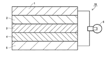
本発明の全固体二次電池は、負極活物質層2、固体電解質層3、及び正極活物質層4をこの順に有する。
図1は、本発明の好ましい実施形態に係る全固体二次電池(リチウムイオン二次電池)を模式化して示す断面図である。本実施形態の全固体二次電池10は、負極側からみて、負極集電体1、負極活物質層2、固体電解質層3、正極活物質層4、正極集電体5を、この順に積層してなる構造を有しており、隣接する層同士は直に接触している。このような構造を採用することで、充電時には、負極側に電子(e−)が供給され、そこにリチウムイオン(Li+)が蓄積される。一方、放電時には、負極に蓄積されたリチウムイオン(Li+)が正極側に戻され、作動部位6に電子を供給することができる。図示した全固体二次電池の例では、作動部位6に電球を採用しており、放電によりこれが点灯するようにされている。
A preferred embodiment of the present invention will be described.
[All-solid secondary battery]
The all solid state secondary battery of the present invention has a negative electrode
FIG. 1 is a cross-sectional view schematically showing an all solid state secondary battery (lithium ion secondary battery) according to a preferred embodiment of the present invention. The all-solid-state
正極活物質層4、固体電解質層3、負極活物質層2の厚さは特に限定されない。一般的な電池の寸法を考慮すると、上記各層の厚さは10〜1,000μmが好ましく、20μm以上500μm未満がより好ましい。
本明細書において、正極活物質層と負極活物質層をあわせて電極層と称することがある。また、正極活物質層には正極活物質が含有され、負極活物質層には負極活物質が含有される。正極活物質及び負極活物質のいずれかを示すのに、あるいは両方を合わせて示すのに、単に活物質または電極活物質と称することがある。固体電解質層は、通常、正極活物質及び/又は負極活物質を含まない。
The thicknesses of the positive electrode active material layer 4, the
In this specification, the positive electrode active material layer and the negative electrode active material layer may be collectively referred to as an electrode layer. The positive electrode active material layer contains a positive electrode active material, and the negative electrode active material layer contains a negative electrode active material. In order to indicate either the positive electrode active material or the negative electrode active material, or to indicate both, the active material or the electrode active material may be simply referred to. The solid electrolyte layer usually does not contain a positive electrode active material and / or a negative electrode active material.
〔負極活物質層、固体電解質層、正極活物質層〕
本発明の全固体二次電池は、負極活物質層2、固体電解質層3及び正極活物質層4のうち、少なくとも1つの層が下記(a)〜(d)を満たす。本発明の全固体二次電池及び電極シートは、少なくとも固体電解質層3が下記(a)〜(d)を満たすことが好ましく、負極活物質層2、固体電解質層3及び正極活物質層4のすべてが下記(a)〜(d)を満たすことも好ましい。
(a)周期律表第1族又は第2族に属する金属の塩であって、イオン伝導性を有する金属塩を含有する。
(b)沸点150〜300℃の溶媒を0.2〜10質量%含有する。
(c)周期律表第1族又は第2族に属する金属のイオンの伝導性を有する無機固体電解質を含有する。
(d)上記(b)の溶媒の含有量に対する上記(a)の金属塩の含有量の比が、モル比で、[金属塩の含有量]/[溶媒の含有量]=1.0/0.1〜1.0/5.0である。
[Negative electrode active material layer, solid electrolyte layer, positive electrode active material layer]
In the all solid state secondary battery of the present invention, at least one of the negative electrode
(A) A metal salt belonging to Group 1 or
(B) 0.2-10 mass% of solvent with a boiling point of 150-300 degreeC is contained.
(C) It contains an inorganic solid electrolyte having conductivity of metal ions belonging to Group 1 or
(D) The ratio of the content of the metal salt of (a) to the content of the solvent of (b) is a molar ratio of [content of metal salt] / [content of solvent] = 1.0 / 0.1-1.0 / 5.0.
上記(a)〜(d)を満たす層中、上記(a)の金属塩(以下、「成分(a)」ともいう。)、上記(b)の溶媒(以下、「成分(b)」ともいう。)、及び上記(c)の無機固体電解質(以下、「成分(c)」ともいう。)は、いずれも層中に均質に存在していること(成分(a)〜(c)が層中に組成物の状態で存在していること)が好ましい。また、上記(a)〜(d)を満たす層中には、上記成分(b)以外の溶媒は実質的に含まれない(すなわち、上記(a)〜(d)を満たす層中、上記成分(b)以外の溶媒の含有量は0.1質量%以下である)。
上記成分(a)〜(c)について順に説明する。
In the layer satisfying the above (a) to (d), the metal salt of the above (a) (hereinafter also referred to as “component (a)”), the solvent of the above (b) (hereinafter referred to as “component (b)”) And the inorganic solid electrolyte (c) (hereinafter also referred to as “component (c)”) are present uniformly in the layer (components (a) to (c) are present). It is preferable that it exists in the composition in the layer. Moreover, in the layer satisfy | filling said (a)-(d), solvent other than the said component (b) is not contained substantially (namely, in the layer satisfy | filling said (a)-(d), the said component The content of the solvent other than (b) is 0.1% by mass or less).
The components (a) to (c) will be described in order.
<成分(a)>
上記成分(a)は、周期律表第1族又は第2族に属する金属の塩であって、イオン伝導性を有する金属塩である。ここで、金属塩が「イオン伝導性を有する」とは、溶媒に溶解した際にイオン伝導性を発現することを意味する。
より詳細には、上記成分(a)は、本発明の全固体二次電池の充電及び放電によって正極と負極との間を往復するイオンを伝導可能な金属塩であり、周期律表第1族又は第2族に属する金属のイオンを伝導可能な金属塩であることが好ましい。本発明の全固体二次電池がリチウムイオン二次電池である場合には、上記成分(a)はリチウムイオンを伝導可能な金属塩である。ここで、「金属イオンを伝導可能」とは、金属イオン伝導性を有することと同義である。
上記成分(a)は、下記(a−1)及び(a−2)から選ばれる金属塩(リチウム塩)であることが好ましい。
<Component (a)>
The component (a) is a metal salt belonging to Group 1 or
More specifically, the component (a) is a metal salt capable of conducting ions that reciprocate between the positive electrode and the negative electrode by charging and discharging of the all-solid-state secondary battery of the present invention. Or it is preferable that it is a metal salt which can conduct | transmit the ion of the metal which belongs to 2nd group. When the all solid state secondary battery of the present invention is a lithium ion secondary battery, the component (a) is a metal salt capable of conducting lithium ions. Here, “capable of conducting metal ions” is synonymous with having metal ion conductivity.
The component (a) is preferably a metal salt (lithium salt) selected from the following (a-1) and (a-2).
(a−1) LiAxDy
(a−1)中、Aは、P、B、As、Sb、Cl、BrもしくはIであるか、又は、P、B、As、Sb、Cl、Br及びIから選ばれる2種以上の元素の組み合わせを示す。Dは、F又はOを示す。xは1〜6であり、1〜3がより好ましい。yは1〜12であり、4〜6がより好ましい。
上記(a−1)の好ましい具体例として、例えば、LiPF6、LiBF4、LiAsF6、及びLiSbF6から選ばれる無機フッ化物塩、並びに、LiClO4、LiBrO4、及びLiIO4から選ばれる過ハロゲン酸塩を挙げることができる。
(A-1) LiA x D y
In (a-1), A is P, B, As, Sb, Cl, Br or I, or two or more elements selected from P, B, As, Sb, Cl, Br and I The combination of is shown. D represents F or O. x is 1-6, and 1-3 are more preferable. y is 1-12, and 4-6 are more preferable.
The Preferred examples of (a-1), for example, LiPF 6, LiBF 4, LiAsF 6, and an inorganic fluoride salt selected from LiSbF 6, as well as perhalogenated selected from LiClO 4, Libro 4, and LiIO 4 There may be mentioned acid salts.
(a−2) LiN(RfSO2)2
(a−2)中、Rfはフッ素原子又はパーフルオロアルキル基を示す。このパーフルオロアルキル基の炭素数は1〜4が好ましく、1〜2がより好ましい。
上記(a−2)の好ましい具体例として、例えば、LiN(CF3SO2)2、LiN(CF3CF2SO2)2、LiN(FSO2)2、及びLiN(CF3SO2)(C4F9SO2)から選ばれるパーフルオロアルカンスルホニルイミド塩を挙げることができる。
(A-2) LiN (R f SO 2 ) 2
In (a-2), R f represents a fluorine atom or a perfluoroalkyl group. 1-4 are preferable and, as for carbon number of this perfluoroalkyl group, 1-2 are more preferable.
As preferable specific examples of the above (a-2), for example, LiN (CF 3 SO 2 ) 2 , LiN (CF 3 CF 2 SO 2 ) 2 , LiN (FSO 2 ) 2 , and LiN (CF 3 SO 2 ) ( And a perfluoroalkanesulfonylimide salt selected from C 4 F 9 SO 2 ).
なかでも、溶媒溶解後のイオン伝導性の観点から、成分(a)は、LiPF6、LiBF4、LiClO4、LiBrO4、LiN(CF3SO2)2、LiN(FSO2)2、及びLiN(CF3SO2)(C4F9SO2)から選ばれる金属塩が好ましく、LiPF6、LiBF4、LiClO4、LiN(CF3SO2)2、及びLiN(FSO2)2から選ばれる金属塩がより好ましく、LiClO4、LiN(CF3SO2)2、及びLiN(FSO2)2から選ばれる金属塩がさらに好ましい。
本発明においては、成分(a)として、1種又は2種以上の金属塩を用いることができる。
上記(a)〜(d)を満たす層中、成分(a)の含有量は2〜60質量%が好ましく、4〜40質量%がより好ましく、6〜20質量%がさらに好ましい。
Among these, from the viewpoint of ion conductivity after dissolution of the solvent, the component (a) includes LiPF 6 , LiBF 4 , LiClO 4 , LiBrO 4 , LiN (CF 3 SO 2 ) 2 , LiN (FSO 2 ) 2 , and LiN. A metal salt selected from (CF 3 SO 2 ) (C 4 F 9 SO 2 ) is preferred, selected from LiPF 6 , LiBF 4 , LiClO 4 , LiN (CF 3 SO 2 ) 2 , and LiN (FSO 2 ) 2. Metal salts are more preferable, and metal salts selected from LiClO 4 , LiN (CF 3 SO 2 ) 2 , and LiN (FSO 2 ) 2 are more preferable.
In the present invention, one or more metal salts can be used as the component (a).
In the layer satisfying the above (a) to (d), the content of the component (a) is preferably 2 to 60% by mass, more preferably 4 to 40% by mass, and further preferably 6 to 20% by mass.
本発明の全固体二次電池において、負極活物質層2、固体電解質層3及び正極活物質層4のうち、上記成分(b)を含有しない層がある場合、この成分(b)を含有しない層には、上記成分(a)が含まれていてもよい。また、負極活物質層2及び正極活物質層4のうち、成分(c)を含有しない層がある場合、この成分(c)を含有しない層には、上記成分(a)が含まれていてもよい。
上記成分(b)を含有しない層中又は上記成分(c)を含有しない層中に上記成分(a)が含まれる場合、上記成分(b)を含有しない層中又は上記成分(c)を含有しない層中、上記成分(a)の含有量は1質量%以下が好ましく、0.5質量%以下がより好ましい。
In the all solid state secondary battery of the present invention, when there is a layer that does not contain the component (b) among the negative electrode
When the component (a) is contained in a layer not containing the component (b) or in a layer not containing the component (c), in a layer not containing the component (b) or containing the component (c) In the layer not to be used, the content of the component (a) is preferably 1% by mass or less, and more preferably 0.5% by mass or less.
<成分(b)>
成分(b)は、沸点150〜300℃の溶媒である。成分(b)の沸点が150〜300℃であることにより、層中に含有させても揮発しにくく、上記成分(a)と共存させることにより両者が混じり合い、イオン伝導性の固形物が形成される。つまり、成分(b)は、層中において流動性のある液体の溶媒として存在するものではない。本発明において、成分(a)と成分(b)を含有してなる固形物は、少なくとも50℃以下において固形物である。この固形物がイオン伝導性を高める理由は定かではないが、固形物が固体電解質の粒子間の空隙に入り込んで空隙を塞ぎ、固体電解質粒子同士の密着性を効果的に高めることが一因と考えられる。
本発明において沸点は1atmにおける沸点(標準沸点)を意味する。
<Component (b)>
Component (b) is a solvent having a boiling point of 150 to 300 ° C. When the boiling point of the component (b) is 150 to 300 ° C., it is difficult to volatilize even if it is contained in the layer, and by mixing it with the component (a), both are mixed and an ion conductive solid is formed. Is done. That is, the component (b) does not exist as a liquid solvent having fluidity in the layer. In the present invention, the solid material containing the component (a) and the component (b) is a solid material at least at 50 ° C. or lower. The reason why this solid matter increases the ionic conductivity is not clear, but it is because the solid matter enters the gaps between the solid electrolyte particles and closes the gaps, effectively increasing the adhesion between the solid electrolyte particles. Conceivable.
In the present invention, the boiling point means a boiling point (standard boiling point) at 1 atm.
上記成分(b)は、本発明の全固体二次電池の、上記(a)〜(d)を満たす層中に0.2〜10質量%含有され、好ましくは1〜9質量%含有され、さらに好ましくは2〜7質量%含有される。このように、本発明においては層中の成分(b)の量は微量であることが必要である。層中の成分(b)の量が0.2〜10質量%であることにより、固体電解質同士の直接的な接触は阻害せずに、固体電解質間に生じた空隙を伝導性の固形物で効果的に塞ぐことができると考えられる。
本発明においては、電池ないし電極シートの各層中に溶媒(液体)が含有されていても、溶媒の総含有量が層中10質量%以下であれば、全固体二次電池と称する。
上記(a)〜(d)を満たす層中には、成分(b)以外の溶媒は事実上含まれない。すなわち、上記(a)〜(d)を満たす層中、成分(b)以外の溶媒の含有量は2質量%以下であり、1質量%以下が好ましく、0.1質量%以下がより好ましい。
The component (b) is contained in the layer satisfying the above (a) to (d) in the all-solid-state secondary battery of the present invention in an amount of 0.2 to 10% by mass, preferably 1 to 9% by mass, More preferably 2 to 7% by mass is contained. Thus, in the present invention, the amount of the component (b) in the layer needs to be a very small amount. When the amount of the component (b) in the layer is 0.2 to 10% by mass, the direct contact between the solid electrolytes is not hindered, and the void formed between the solid electrolytes is made of a conductive solid. It is thought that it can be effectively blocked.
In the present invention, even if a solvent (liquid) is contained in each layer of the battery or electrode sheet, it is referred to as an all-solid secondary battery if the total content of the solvent is 10% by mass or less in the layer.
In the layer satisfying the above (a) to (d), a solvent other than the component (b) is practically not contained. That is, in the layer satisfying the above (a) to (d), the content of the solvent other than the component (b) is 2% by mass or less, preferably 1% by mass or less, and more preferably 0.1% by mass or less.
成分(b)は、成分(a)の溶解性の観点から、その化学構造中に*−CN、*−O−*、*−O−C(=O)−*、*−C(=O)−NRS1−*(RS1は水素原子又は置換基を示す)、*−O−C(=O)−O−*、=NRS2(RS2は水素原子又は置換基を示す)、*=N−*、*−NH−C(=O)−O−*、及び*−OHから選ばれる基を有することが好ましく、*−O−C(=O)−O−*、*−CN、*−O−C(=O)−*、*−O−*から選ばれる基を有することがより好ましい。
上記RS1及びRS2は水素原子、フッ素原子、塩素原子、臭素原子、ヨウ素原子又は置換基を示す。この置換基の好ましい例として、アルキル基(好ましくは炭素数1〜12、より好ましくは炭素数1〜6、さらに好ましくは炭素数1〜3のアルキル基)、アリール基(好ましくは炭素数6〜20、より好ましくは炭素数6〜15、さらに好ましくは炭素数6〜10のアリール基)、及びアルケニル基(好ましくは炭素数2〜18、より好ましくは炭素数2〜12のアルケニル基)を挙げることができる。また、上記アルキル基はフッ素原子を有するアルキル基であることも好ましい。上記RS1及びRS2は水素原子、アルキル基、アリール基、又はフッ素原子であることがより好ましい。
上記*は溶媒の化学構造中に組み込まれた状態における連結部位を示す。
From the viewpoint of solubility of the component (a), the component (b) has * -CN, * -O- *, * -O-C (= O)-*, * -C (= O in its chemical structure. ) -NR S1- * (R S1 represents a hydrogen atom or a substituent), * -O-C (= O) -O- *, = NR S2 (R S2 represents a hydrogen atom or a substituent), * It preferably has a group selected from N— *, * —NH—C (═O) —O— *, and * —OH, * —O—C (═O) —O— *, * —CN. , * —O—C (═O) — * and * —O— * are more preferable.
R S1 and R S2 represent a hydrogen atom, a fluorine atom, a chlorine atom, a bromine atom, an iodine atom or a substituent. Preferred examples of this substituent include an alkyl group (preferably an alkyl group having 1 to 12 carbon atoms, more preferably an alkyl group having 1 to 6 carbon atoms, and still more preferably an alkyl group having 1 to 3 carbon atoms), an aryl group (preferably having 6 to 6 carbon atoms) 20, more preferably an aryl group having 6 to 15 carbon atoms, still more preferably an aryl group having 6 to 10 carbon atoms), and an alkenyl group (preferably an alkenyl group having 2 to 18 carbon atoms, more preferably an alkenyl group having 2 to 12 carbon atoms). be able to. The alkyl group is preferably an alkyl group having a fluorine atom. R S1 and R S2 are more preferably a hydrogen atom, an alkyl group, an aryl group, or a fluorine atom.
The above * indicates a linking site in a state incorporated in the chemical structure of the solvent.
成分(b)は、その沸点が180〜300℃であることがより好ましく、200〜280℃がさらに好ましい。成分(b)として採用しうる溶媒の好ましい具体例として、例えば、エチレンカーボネート(261℃)、プロピレンカーボネート(240℃)、フルオロエチレンカーボネート(210℃)、ベンゾニトリル(190℃)、γ−ブチロラクトン(204℃)、γ−バレロラクトン(207℃)、グルタロニトリル(285℃)、アジポニトリル(295℃)、3−メトキシプロピオニトリル(164℃)、スルホラン(285℃)、燐酸トリメチル(197℃)、ジメチルスルホキシド(189℃)、エチレングリコール(198℃)、ジエチレングリコール(245℃)、エチレングリコールモノエチルエーテルアセテート(156℃)、テトラエチレングリコールジメチルエーテル(275℃)、ジメチルホルムアミド(153℃)を挙げることができる。これらは、1種単独で用いても2種以上を併用してもよい。
なかでも成分(a)の溶解性、イオン伝導性の観点から、エチレンカーボネート(261℃)、プロピレンカーボネート(240℃)、フルオロエチレンカーボネート(210℃)、ベンゾニトリル(190℃)、γ−ブチロラクトン(204℃)、γ−バレロラクトン(207℃)、グルタロニトリル(285℃)、アジポニトリル(295℃)、エチレングリコールモノエチルエーテルアセテート(156℃)、及びテトラエチレングリコールジメチルエーテル(275℃)から選ばれる1種又は2種以上の溶媒を用いることが好ましい。
上記括弧内の温度は沸点を示す。
As for a component (b), it is more preferable that the boiling point is 180-300 degreeC, and 200-280 degreeC is further more preferable. Preferable specific examples of the solvent that can be used as the component (b) include, for example, ethylene carbonate (261 ° C.), propylene carbonate (240 ° C.), fluoroethylene carbonate (210 ° C.), benzonitrile (190 ° C.), γ-butyrolactone ( 204 ° C), γ-valerolactone (207 ° C), glutaronitrile (285 ° C), adiponitrile (295 ° C), 3-methoxypropionitrile (164 ° C), sulfolane (285 ° C), trimethyl phosphate (197 ° C) Dimethyl sulfoxide (189 ° C.), ethylene glycol (198 ° C.), diethylene glycol (245 ° C.), ethylene glycol monoethyl ether acetate (156 ° C.), tetraethylene glycol dimethyl ether (275 ° C.), dimethylformamide (153 ° C.). I can make it. These may be used alone or in combination of two or more.
Among these, from the viewpoints of solubility and ion conductivity of component (a), ethylene carbonate (261 ° C.), propylene carbonate (240 ° C.), fluoroethylene carbonate (210 ° C.), benzonitrile (190 ° C.), γ-butyrolactone ( 204 ° C), γ-valerolactone (207 ° C), glutaronitrile (285 ° C), adiponitrile (295 ° C), ethylene glycol monoethyl ether acetate (156 ° C), and tetraethylene glycol dimethyl ether (275 ° C). It is preferable to use one or more solvents.
The temperature in the parenthesis indicates the boiling point.
上記(a)〜(d)を満たす層中において、成分(b)の含有量に対する成分(a)の含有量の比は、モル比で、[成分(a)の含有量]/[成分(b)の含有量]=1.0/0.1〜1.0/5.0であり、イオン伝導性、安全性の観点から、1.0/0.2〜1.0/3.0が好ましく、1.0/0.4〜1.0/2.0がより好ましく、1.0/0.4〜1.0/1.8がさらに好ましく、1.0/0.5〜1.0/1.5がさらに好ましい。 In the layer satisfying the above (a) to (d), the ratio of the content of the component (a) to the content of the component (b) is a molar ratio [content of component (a)] / [component ( b) Content] = 1.0 / 0.1 to 1.0 / 5.0, and 1.0 / 0.2 to 1.0 / 3.0 from the viewpoint of ion conductivity and safety. Is preferable, 1.0 / 0.4 to 1.0 / 2.0 is more preferable, 1.0 / 0.4 to 1.0 / 1.8 is more preferable, and 1.0 / 0.5 to 1 0.0 / 1.5 is more preferable.
<成分(c)>
成分(c)は、周期律表第1族又は第2族に属する金属のイオンの伝導性を有する無機固体電解質(すなわち、周期律表第1族又は第2族に属する金属のイオンを伝導可能な無機固体電解質)である。より詳細には、本発明の全固体二次電池の充電及び放電によって正極と負極との間を往復する金属イオンを伝導可能な無機固体電解質である。無機固体電解質が伝導することができる上記金属イオンは、リチウムイオン又はナトリウムイオンであることが好ましい。上記無機固体電解質について詳細に説明する。
<Component (c)>
Component (c) is an inorganic solid electrolyte having conductivity of metal ions belonging to Group 1 or
本発明において無機固体電解質とは、無機の固体電解質のことであり、固体電解質とは、その内部において少なくとも上記特定の金属イオンを移動させることができる固体状の電解質のことである。主たるイオン伝導性材料として有機物を含むものではないことから、有機固体電解質(PEOなどに代表される高分子電解質、LiTFSIなどに代表される有機電解質塩)とは明確に区別される。また、無機固体電解質は定常状態では固体であるため、通常カチオンおよびアニオンに解離または遊離していない。この点で、電解液や、カチオンおよびアニオンが解離または遊離している無機電解質塩(LiPF6、LiBF4,LiFSI,LiClなど)とも明確に区別される。無機固体電解質は通常は電子伝導性を有さない。 In the present invention, the inorganic solid electrolyte is an inorganic solid electrolyte, and the solid electrolyte is a solid electrolyte capable of moving at least the specific metal ion therein. Since it does not contain organic substances as the main ion conductive material, it is clearly distinguished from organic solid electrolytes (polymer electrolytes typified by PEO and the like, organic electrolyte salts typified by LiTFSI and the like). In addition, since the inorganic solid electrolyte is solid in a steady state, it is not usually dissociated or released into cations and anions. In this respect, it is also clearly distinguished from the electrolyte solution and inorganic electrolyte salts (LiPF 6 , LiBF 4 , LiFSI, LiCl, etc.) in which cations and anions are dissociated or liberated. Inorganic solid electrolytes usually do not have electronic conductivity.
本発明に採用しうる上記無機固体電解質は、この種の製品に適用される固体電解質材料を適宜選定して用いることができる。無機固体電解質は(i)硫化物系無機固体電解質と(ii)酸化物系無機固体電解質が代表例として挙げられる。 As the inorganic solid electrolyte that can be employed in the present invention, a solid electrolyte material applied to this type of product can be appropriately selected and used. Typical examples of inorganic solid electrolytes include (i) sulfide-based inorganic solid electrolytes and (ii) oxide-based inorganic solid electrolytes.
(i)硫化物系無機固体電解質
硫化物系無機固体電解質は、硫黄(S)を含有し、かつ、周期律表第1族または第2族に属する金属のイオン伝導性を有し、かつ、電子絶縁性を有するものが好ましい。硫化物系無機固体電解質は、元素として少なくともLi、SおよびPを含有し、リチウムイオン伝導性を有しているものが好ましいが、目的または場合に応じて、Li、SおよびP以外の他の元素を含んでもよい。
例えば下記式(1)で示される組成を満たすリチウムイオン伝導性無機固体電解質が挙げられる。
La1Mb1Pc1Sd1Ae1 (1)
式(1)中、LはLi、NaおよびKから選択される元素を示し、Liが好ましい。
Mは、B、Zn、Sn、Si、Cu、Ga、Sb、Al及びGeから選択される元素を示す。なかでもMは、B、Sn、Si、Al又はGeが好ましく、Sn、Al又はGeがより好ましい。Aは、I、Br、Cl又はFを示し、I又はBrが好ましく、Iが特に好ましい。a1〜e1は各元素の組成比を示し、a1:b1:c1:d1:e1は1〜12:0〜1:1:2〜12:0〜5を満たす。a1は1〜9が好ましく、1.5〜4がより好ましい。b1は0〜0.5が好ましい。d1は3〜7が好ましく、3.25〜4.5がより好ましい。e1は0〜3が好ましく、0〜1がより好ましい。
(I) Sulfide-based inorganic solid electrolyte The sulfide-based inorganic solid electrolyte contains sulfur (S) and has ion conductivity of a metal belonging to Group 1 or
For example, a lithium ion conductive inorganic solid electrolyte that satisfies the composition represented by the following formula (1) can be given.
L a1 M b1 P c1 S d1 A e1 (1)
In the formula (1), L represents an element selected from Li, Na and K, and Li is preferable.
M represents an element selected from B, Zn, Sn, Si, Cu, Ga, Sb, Al, and Ge. Among these, M is preferably B, Sn, Si, Al, or Ge, and more preferably Sn, Al, or Ge. A represents I, Br, Cl or F, preferably I or Br, and particularly preferably I. a1 to e1 indicate the composition ratio of each element, and a1: b1: c1: d1: e1 satisfies 1 to 12: 0 to 1: 1: 2 to 12: 0 to 5. a1 is preferably 1 to 9, and more preferably 1.5 to 4. b1 is preferably 0 to 0.5. d1 is preferably from 3 to 7, and more preferably from 3.25 to 4.5. e1 is preferably 0 to 3, and more preferably 0 to 1.
式(1)において、L、M、P、S及びAの組成比は、好ましくはb1、e1が0であり、より好ましくはb1=0、e1=0で且つa1、c1及びd1の比がa1:c1:d1=1〜9:1:3〜7であり、さらに好ましくはb1=0、e1=0で且つa1:c1:d1=1.5〜4:1:3.25〜4.5である。各元素の組成比は、後述するように、硫化物系固体電解質を製造する際の原料化合物の配合量を調整することにより制御できる。 In the formula (1), the composition ratio of L, M, P, S and A is preferably such that b1 and e1 are 0, more preferably b1 = 0 and e1 = 0 and the ratio of a1, c1 and d1 is a1: c1: d1 = 1-9: 1: 3-7, more preferably b1 = 0, e1 = 0 and a1: c1: d1 = 1.5-4: 1: 3.25-4. 5. As will be described later, the composition ratio of each element can be controlled by adjusting the blending amount of the raw material compound in producing the sulfide-based solid electrolyte.
上記硫化物系無機固体電解質は、非結晶(ガラス)であっても結晶化(ガラスセラミックス化)していてもよく、一部のみが結晶化していてもよい。例えば、Li、PおよびSを含有するLi−P−S系ガラス、またはLi、PおよびSを含有するLi−P−S系ガラスセラミックスを用いることができる。
上記硫化物系無機固体電解質は、[1]硫化リチウム(Li2S)と硫化リン(例えば五硫化二燐(P2S5))、[2]硫化リチウムと単体燐および単体硫黄の少なくとも一方、または[3]硫化リチウムと硫化リン(例えば五硫化二燐(P2S5))と単体燐および単体硫黄の少なくとも一方、の反応により製造することができる。
The sulfide-based inorganic solid electrolyte may be amorphous (glass) or crystallized (glass ceramic), or only part of it may be crystallized. For example, Li—PS—S glass containing Li, P and S, or Li—PS glass glass ceramic containing Li, P and S can be used.
The sulfide-based inorganic solid electrolyte includes [1] at least one of lithium sulfide (Li 2 S) and phosphorus sulfide (for example, diphosphorus pentasulfide (P 2 S 5 )), [2] lithium sulfide, simple phosphorus, and simple sulfur. Or [3] It can be produced by the reaction of lithium sulfide, phosphorus sulfide (for example, diphosphorus pentasulfide (P 2 S 5 )) and at least one of elemental phosphorus and elemental sulfur.
Li−P−S系ガラスおよびLi−P−S系ガラスセラミックスにおける、Li2SとP2S5との比率は、Li2S:P2S5のモル比で、好ましくは65:35〜85:15、より好ましくは68:32〜77:23である。Li2SとP2S5との比率をこの範囲にすることにより、リチウムイオン伝導度をより高めることができる。具体的には、リチウムイオン伝導度を好ましくは1×10⁻⁴S/cm以上、より好ましくは1×10−3S/cm以上とすることができる。上限は特にないが、1×10−1S/cm以下であることが実際的である。 The ratio of Li 2 S to P 2 S 5 in the Li—PS glass and the Li—PS glass glass ceramic is a molar ratio of Li 2 S: P 2 S 5 , preferably 65:35 to 35:35. 85:15, more preferably 68:32 to 77:23. By setting the ratio of Li 2 S to P 2 S 5 within this range, the lithium ion conductivity can be further increased. Specifically, the lithium ion conductivity can be preferably 1 × 10 −4 S / cm or more, more preferably 1 × 10 −3 S / cm or more. Although there is no upper limit, it is practical that it is 1 × 10 −1 S / cm or less.
具体的な化合物例としては、例えばLi2Sと、第13族〜第15族の元素の硫化物とを含有する原料組成物を用いてなるものを挙げることができる。具体的には、Li2S−P2S5、Li2S−LiI−P2S5、Li2S−LiI−Li2O−P2S5、Li2S−LiBr−P2S5、Li2S−Li2O−P2S5、Li2S−Li3PO4−P2S5、Li2S−P2S5−P2O5、Li2S−P2S5−SiS2、Li2S−P2S5−SnS、Li2S−P2S5−Al2S3、Li2S−GeS2、Li2S−GeS2−ZnS、Li2S−Ga2S3、Li2S−GeS2−Ga2S3、Li2S−GeS2−P2S5、Li2S−GeS2−Sb2S5、Li2S−GeS2−Al2S3、Li2S−SiS2、Li2S−Al2S3、Li2S−SiS2−Al2S3、Li2S−SiS2−P2S5、Li2S−SiS2−P2S5−LiI、Li2S−SiS2−LiI、Li2S−SiS2−Li4SiO4、Li2S−SiS2−Li3PO4、Li10GeP2S12などが挙げられる。その中でも、Li2S−P2S5、Li2S−GeS2−Ga2S3、Li2S−SiS2−P2S5、Li2S−SiS2−Li4SiO4、Li2S−SiS2−Li3PO4、Li2S−LiI−Li2O−P2S5、Li2S−Li2O−P2S5、Li2S−Li3PO4−P2S5、Li2S−GeS2−P2S5、Li10GeP2S12からなる結晶質およびまたは非晶質の原料組成物が、高いリチウムイオン伝導性を有するので好ましい。このような原料組成物を用いて硫化物固体電解質材料を合成する方法としては、例えば非晶質化法を挙げることができる。非晶質化法としては、例えば、メカニカルミリング法および溶融急冷法を挙げることができ、中でもメカニカルミリング法が好ましい。常温での処理が可能になり、製造工程の簡略化を図ることができるからである。
Specific examples of the compound include those using a raw material composition containing, for example, Li 2 S and a sulfide of an element belonging to Group 13 to
(ii)酸化物系無機固体電解質
酸化物系無機固体電解質は、酸素(O)を含有し、かつ、周期律表第1族または第2族に属する金属のイオン伝導性を有し、かつ、電子絶縁性を有するものが好ましい。
(Ii) Oxide-based inorganic solid electrolyte The oxide-based inorganic solid electrolyte contains oxygen (O) and has ionic conductivity of a metal belonging to Group 1 or
具体的な化合物例としては、例えばLixaLayaTiO3〔xaは0.3≦xa≦0.7を満たし、yaは0.3≦ya≦0.7を満たす。〕(LLT); LixbLaybZrzbMbb mbOnb(MbbはAl、Mg、Ca、Sr、V、Nb、Ta、Ti、Ge、InもしくはSnであるか、又は、Al、Mg、Ca、Sr、V、Nb、Ta、Ti、Ge、In及びSnから選ばれる2種以上の元素の組み合わせである。xbは5≦xb≦10を満たし、ybは1≦yb≦4を満たし、zbは1≦zb≦4を満たし、mbは0≦mb≦2を満たし、nbは5≦nb≦20を満たす。); LixcBycMcc zcOnc(MccはC、S、Al、Si、Ga、Ge、InもしくはSnであるか、又は、C、S、Al、Si、Ga、Ge、In及びSnから選ばれる2種以上の元素の組み合わせである。xcは0≦xc≦5を満たし、ycは0≦yc≦1を満たし、zcは0≦zc≦1を満たし、ncは0≦nc≦6を満たす。); Lixd(Al,Ga)yd(Ti,Ge)zdSiadPmdOnd(xdは1≦xd≦3を満たし、ydは0≦yd≦1を満たし、zdは0≦zd≦2を満たし、adは0≦ad≦1を満たし、mdは1≦md≦7を満たし、ndは3≦nd≦13を満たす。); Li(3−2xe)Mee xeDeeO(xeは0以上0.1以下の数を表し、Meeは2価の金属原子を表す。Deeはハロゲン原子または2種以上のハロゲン原子の組み合わせを表す。); LixfSiyfOzf(xfは1≦xf≦5を満たし、yfは0<yf≦3を満たし、zfは1≦zf≦10を満たす。); LixgSygOzg(xgは1≦xg≦3を満たし、ygは0<yg≦2を満たし、zgは1≦zg≦10を満たす。); Li3BO3−Li2SO4; Li2O−B2O3−P2O5; Li2O−SiO2; Li6BaLa2Ta2O12; Li3PO(4−3/2w)Nw(wはw<1); LISICON(Lithium super ionic conductor)型結晶構造を有するLi3.5Zn0.25GeO4; ペロブスカイト型結晶構造を有するLa0.55Li0.35TiO3; NASICON(Natrium super ionic conductor)型結晶構造を有するLiTi2P3O12; Li1+xh+yh(Al,Ga)xh(Ti,Ge)2−xhSiyhP3−yhO12(xhは0≦xh≦1を満たし、yhは0≦yh≦1を満たす。); ガーネット型結晶構造を有するLi7La3Zr2O12(LLZ)等が挙げられる。またLi、P及びOを含むリン化合物も望ましい。例えばリン酸リチウム(Li3PO4); リン酸リチウムの酸素の一部を窒素で置換したLiPON; LiPOD1(D1は、好ましくは、Ti、V、Cr、Mn、Fe、Co、Ni、Cu、Zr、Nb、Mo、Ru、Ag、Ta、W、PtもしくはAuであるか、又は、Ti、V、Cr、Mn、Fe、Co、Ni、Cu、Zr、Nb、Mo、Ru、Ag、Ta、W、Pt及びAuから選ばれる2種以上の元素の組み合わせである。)等が挙げられる。また、LiA1ON(A1は、好ましくは、Si、B、Ge、Al、CもしくはGaであるか、又は、Si、B、Ge、Al、C及びGaから選ばれる2種以上の元素の組み合わせである。)等も好ましく用いることができる。
As a specific compound example, for example, Li xa La ya TiO 3 [xa satisfies 0.3 ≦ xa ≦ 0.7, and ya satisfies 0.3 ≦ ya ≦ 0.7. (LLT); Li xb La yb Zr zb M bb mb Onb (M bb is Al, Mg, Ca, Sr, V, Nb, Ta, Ti, Ge, In or Sn, or Al, Mg , Ca, Sr, V, Nb, Ta, Ti, Ge, In and Sn are combinations of two or more elements, xb satisfies 5 ≦ xb ≦ 10, and yb satisfies 1 ≦ yb ≦ 4 , Zb satisfies 1 ≦ zb ≦ 4, mb satisfies 0 ≦ mb ≦ 2, and nb satisfies 5 ≦ nb ≦ 20; Li xc B yc M cc zc O nc (M cc is C, S, Al, Si, Ga, Ge, In, or Sn, or a combination of two or more elements selected from C, S, Al, Si, Ga, Ge, In, and Sn, where xc is 0 ≦ xc ≦ 5, yc satisfies 0 ≦ yc ≦ 1 And, zc satisfies 0 ≦ zc ≦ 1, nc satisfies 0 ≦ nc ≦ 6);. Li xd (Al, Ga) yd (Ti, Ge) zd Si ad P md O nd (xd is 1 ≦ xd ≦ 3, yd satisfies 0 ≦ yd ≦ 1, zd satisfies 0 ≦ zd ≦ 2, ad satisfies 0 ≦ ad ≦ 1, md satisfies 1 ≦ md ≦ 7, nd satisfies 3 ≦ nd ≦ 13 meet);. Li (3-2xe) M ee xe D ee O (xe represents a number of 0 to 0.1, .D ee M ee is representative of a divalent metal atom is a halogen atom or Li xf Si yf O zf (xf satisfies 1 ≦ xf ≦ 5, yf satisfies 0 <yf ≦ 3, and zf satisfies 1 ≦ zf ≦ 10). ); Li xg S yg O zg (xg satisfies 1 ≦ xg ≦ 3 yg satisfies 0 <yg ≦ 2, zg satisfies 1 ≦ zg ≦ 10);.
無機固体電解質の体積平均粒子径は特に限定されないが、0.01μm以上であることが好ましく、0.1μm以上であることがより好ましい。上限としては、100μm以下であることが好ましく、50μm以下であることがより好ましい。なお、無機固体電解質粒子の平均粒子径の測定は、以下の手順で行う。無機固体電解質粒子を、水(水に不安定な物質の場合はヘプタン)を用いて20mlサンプル瓶中で1質量%の分散液を希釈調整する。希釈後の分散試料は、1kHzの超音波を10分間照射し、その直後に試験に使用する。この分散液試料を用い、レーザ回折/散乱式粒度分布測定装置LA−920(HORIBA社製)を用いて、温度25℃で測定用石英セルを使用してデータ取り込みを50回行い、体積平均粒子径を得る。その他の詳細な条件等は必要によりJISZ8828:2013「粒子径解析−動的光散乱法」の記載を参照する。1水準につき5つの試料を作製しその平均値を採用する。 The volume average particle diameter of the inorganic solid electrolyte is not particularly limited, but is preferably 0.01 μm or more, and more preferably 0.1 μm or more. As an upper limit, it is preferable that it is 100 micrometers or less, and it is more preferable that it is 50 micrometers or less. In addition, the measurement of the average particle diameter of an inorganic solid electrolyte particle is performed in the following procedures. The inorganic solid electrolyte particles are diluted and adjusted in a 20 ml sample bottle using water (heptane in the case of a substance unstable to water). The diluted dispersion sample is irradiated with 1 kHz ultrasonic waves for 10 minutes and used immediately after that. Using this dispersion liquid sample, using a laser diffraction / scattering particle size distribution measuring apparatus LA-920 (manufactured by HORIBA), data acquisition was performed 50 times using a quartz cell for measurement at a temperature of 25 ° C. Get the diameter. For other detailed conditions and the like, refer to the description of JISZ8828: 2013 “Particle Size Analysis—Dynamic Light Scattering Method” as necessary. Five samples are prepared for each level, and the average value is adopted.
本発明の全固体二次電池において、上記(a)〜(d)を満たす層中における成分(c)の含有量は、この層の機能(固体電解質層であるか、あるいは電極層であるか)によって適宜に調節されるものである。上記(a)〜(d)を満たす層が固体電解質層である場合、この固体電解質層中の上記成分(c)の含有量は5〜98質量%が好ましく、10〜97質量%がより好ましく、20〜95質量%がさらに好ましく、30〜92質量%がさらに好ましく、40〜90質量%がさらに好ましい。
また、上記(a)〜(d)を満たす層が電極層である場合、この電極層中の上記成分(c)の含有量は2〜90質量%が好ましく、5〜90質量%がより好ましく、10〜90質量%がさらに好ましく、20〜80質量%がさらに好ましく、20〜70質量%がさらに好ましく、20〜50質量%がさらに好ましく、25〜40質量%がさらに好ましい。
上記無機固体電解質は、1種を単独で用いても、2種以上を組み合わせて用いてもよい。
In the all-solid-state secondary battery of the present invention, the content of the component (c) in the layer satisfying the above (a) to (d) is the function of this layer (whether it is a solid electrolyte layer or an electrode layer). ) Is adjusted appropriately. When the layer satisfying the above (a) to (d) is a solid electrolyte layer, the content of the component (c) in the solid electrolyte layer is preferably 5 to 98% by mass, more preferably 10 to 97% by mass. 20-95 mass% is further more preferable, 30-92 mass% is further more preferable, and 40-90 mass% is further more preferable.
Moreover, when the layer satisfy | filling said (a)-(d) is an electrode layer, 2-90 mass% is preferable, and, as for content of the said component (c) in this electrode layer, 5-90 mass% is more preferable. 10 to 90 mass% is more preferable, 20 to 80 mass% is further preferable, 20 to 70 mass% is further preferable, 20 to 50 mass% is further preferable, and 25 to 40 mass% is further preferable.
The said inorganic solid electrolyte may be used individually by 1 type, or may be used in combination of 2 or more type.
本発明の全固体二次電池において、負極活物質層2、固体電解質層3及び正極活物質層4のうち、上記成分(a)を含有しない層がある場合、この成分(a)を含有しない層には、上記成分(c)が含まれていることが好ましい。また、負極活物質層2、固体電解質層3及び正極活物質層4のうち、上記成分(b)を含有しない層がある場合、この成分(b)を含有しない層にも、上記成分(c)が含まれていることが好ましい。つまり、成分(c)は、負極活物質層2、固体電解質層3及び正極活物質層4のすべての層に含まれていることが好ましい。
上記成分(a)又は上記成分(b)を含有しない層中に上記成分(c)が含まれる場合、上記成分(a)又は上記成分(b)を含有しない層中の上記成分(c)の含有量は、層の機能(固体電解質層であるか、あるいは電極層であるか)によって適宜に調節されるものである。上記成分(a)又は上記成分(b)を含有しない層が固体電解質層である場合には、この固体電解質層中の上記成分(c)の含有量は、10〜99.5質量%が好ましく、より好ましくは20〜99質量%、さらに好ましくは30〜98質量%、さらに好ましくは40〜98質量%、さらに好ましくは50〜95質量%、さらに好ましくは60〜93質量%、さらに好ましくは70〜90質量%、さらに好ましくは80〜90質量%である。
また、上記成分(a)又は上記成分(b)を含有しない層が電極層である場合、この電極層中の上記成分(c)の含有量は2〜90質量%が好ましく、5〜90質量%がより好ましく、10〜90質量%がさらに好ましく、20〜80質量%がさらに好ましく、20〜70質量%がさらに好ましく、25〜40質量%がさらに好ましい。
In the all solid state secondary battery of the present invention, when there is a layer that does not contain the component (a) among the negative electrode
When the component (c) is contained in a layer not containing the component (a) or the component (b), the component (c) in the layer not containing the component (a) or the component (b) The content is appropriately adjusted depending on the function of the layer (whether it is a solid electrolyte layer or an electrode layer). When the layer not containing the component (a) or the component (b) is a solid electrolyte layer, the content of the component (c) in the solid electrolyte layer is preferably 10 to 99.5% by mass. More preferably, it is 20-99 mass%, More preferably, it is 30-98 mass%, More preferably, it is 40-98 mass%, More preferably, it is 50-95 mass%, More preferably, it is 60-93 mass%, More preferably, it is 70 It is -90 mass%, More preferably, it is 80-90 mass%.
Moreover, when the layer which does not contain the said component (a) or the said component (b) is an electrode layer, 2-90 mass% is preferable, and, as for content of the said component (c) in this electrode layer, 5-90 mass. % Is more preferable, 10 to 90% by mass is further preferable, 20 to 80% by mass is further preferable, 20 to 70% by mass is further preferable, and 25 to 40% by mass is further preferable.
本発明の全固体二次電池は、上記(a)〜(d)を満たす層において、成分(a)(金属塩)の含有量と、成分(b)(溶媒)の含有量と、成分(c)(無機固体電解質)の含有量の比が、質量比で、[成分(a)の含有量]/[成分(b)の含有量]/[成分(c)の含有量]=3〜50/0.5〜10/50〜98であることが好ましく、6〜15/1.5〜5/80〜90であることがより好ましい。上記好ましい範囲内とすることにより、イオン伝導性をより高めることができる。 In the layer satisfying the above (a) to (d), the all solid secondary battery of the present invention includes the content of the component (a) (metal salt), the content of the component (b) (solvent), and the component ( c) Content ratio of (inorganic solid electrolyte) is mass ratio, [content of component (a)] / [content of component (b)] / [content of component (c)] = 3 It is preferable that it is 50 / 0.5-10 / 50-98, and it is more preferable that it is 6-15 / 1.5-5 / 80-90. By setting it within the preferable range, ion conductivity can be further increased.
<バインダー>
本発明の全固体二次電池において、各層(すなわち、負極活物質層、固体電解質層及び/又は正極活物質層、以下同様。)はバインダーを含有することも好ましい。本発明で使用することができるバインダーは、有機ポリマーであれば特に限定されない。
本発明に用いることができるバインダーは、通常、電池材料の正極または負極用結着剤として用いられるバインダーが好ましく、特に制限はなく、例えば、以下に述べる樹脂からなるバインダーが好ましい。
<Binder>
In the all solid state secondary battery of the present invention, each layer (that is, a negative electrode active material layer, a solid electrolyte layer and / or a positive electrode active material layer, the same shall apply hereinafter) preferably contains a binder. The binder that can be used in the present invention is not particularly limited as long as it is an organic polymer.
The binder that can be used in the present invention is preferably a binder that is usually used as a binder for a positive electrode or a negative electrode of a battery material, and is not particularly limited. For example, a binder made of a resin described below is preferable.
含フッ素樹脂としては、例えば、ポリテトラフルオロエチレン(PTFE)、ポリビニレンジフルオリド(PVdF)、ポリビニレンジフルオリドとヘキサフルオロプロピレンの共重合物(PVdF−HFP)が挙げられる
炭化水素系熱可塑性樹脂としては、例えば、ポリエチレン、ポリプロピレン、スチレンブタジエンゴム(SBR)、水素添加スチレンブタジエンゴム(HSBR)、ブチレンゴム、アクリロニトリルブタジエンゴム、ポリブタジエン、ポリイソプレン、ポリイソプレンラテックスが挙げられる。
アクリル樹脂としては、例えば、ポリ(メタ)アクリル酸メチル、ポリ(メタ)アクリル酸エチル、ポリ(メタ)アクリル酸イソプロピル、ポリ(メタ)アクリル酸イソブチル、ポリ(メタ)アクリル酸ブチル、ポリ(メタ)アクリル酸ヘキシル、ポリ(メタ)アクリル酸オクチル、ポリ(メタ)アクリル酸ドデシル、ポリ(メタ)アクリル酸ステアリル、ポリ(メタ)アクリル酸2−ヒドロキシエチル、ポリ(メタ)アクリル酸、ポリ(メタ)アクリル酸ベンジル、ポリ(メタ)アクリル酸グリシジル、ポリ(メタ)アクリル酸ジメチルアミノプロピル、およびこれら樹脂を構成するモノマーの共重合体が挙げられる。
ウレタン樹脂としては、例えば、ポリウレタンが挙げられる。
またそのほかのビニル系モノマーとの共重合体も好適に用いられる。例えばポリ(メタ)アクリル酸メチルーポリスチレン共重合体、ポリ(メタ)アクリル酸メチルーアクリロニトリル共重合体、ポリ(メタ)アクリル酸ブチルーアクリロニトリル-スチレン共重合体などが挙げられる。
これらは1種を単独で用いても、2種以上を組み合わせて用いてもよい。
Examples of the fluorine-containing resin include polytetrafluoroethylene (PTFE), polyvinylidene fluoride (PVdF), and a copolymer of polyvinylidene fluoride and hexafluoropropylene (PVdF-HFP). Examples of the plastic resin include polyethylene, polypropylene, styrene butadiene rubber (SBR), hydrogenated styrene butadiene rubber (HSBR), butylene rubber, acrylonitrile butadiene rubber, polybutadiene, polyisoprene, and polyisoprene latex.
Examples of the acrylic resin include poly (meth) methyl acrylate, poly (meth) ethyl acrylate, poly (meth) acrylate isopropyl, poly (meth) acrylate isobutyl, poly (meth) butyl acrylate, poly (meth) ) Hexyl acrylate, poly (meth) acrylate octyl, poly (meth) acrylate dodecyl, poly (meth) acrylate stearyl, poly (meth) acrylate 2-hydroxyethyl, poly (meth) acrylic acid, poly (meth) ) Benzyl acrylate, poly (meth) acrylate glycidyl, poly (meth) acrylate dimethylaminopropyl, and copolymers of monomers constituting these resins.
Examples of the urethane resin include polyurethane.
Further, copolymers with other vinyl monomers are also preferably used. Examples include poly (meth) acrylate methyl-polystyrene copolymer, poly (meth) acrylate methyl-acrylonitrile copolymer, poly (meth) acrylate butyl-acrylonitrile-styrene copolymer, and the like.
These may be used individually by 1 type, or may be used in combination of 2 or more type.
本発明に用いることができるバインダーはポリマー粒子であることが好ましく、ポリマー粒子の平均粒子径φは、0.01μm〜100μmが好ましく、0.05μm〜50μmがより好ましく、0.05μm〜20μmがさらに好ましい。平均粒子径φが上記好ましい範囲内にあることが出力密度向上の観点から好ましい。 The binder that can be used in the present invention is preferably polymer particles, and the average particle diameter φ of the polymer particles is preferably 0.01 μm to 100 μm, more preferably 0.05 μm to 50 μm, and further preferably 0.05 μm to 20 μm. preferable. It is preferable from the viewpoint of improving the output density that the average particle diameter φ is in the above preferred range.
本発明に用いることができるポリマー粒子の平均粒子径φは、特に断らない限り、以下に記載の測定条件および定義によるものとする。
ポリマー粒子を任意の溶媒(固体電解質組成物の調製に用いる有機溶媒、例えば、ヘプタン)を用いて20mlサンプル瓶中で1質量%の分散液を希釈調製する。希釈後の分散試料は、1kHzの超音波を10分間照射し、その直後に試験に使用する。この分散液試料を用い、レーザ回折/散乱式粒度分布測定装置LA−920(商品名、HORIBA社製)を用いて、温度25℃で測定用石英セルを使用してデータ取り込みを50回行い、得られた体積平均粒子径を平均粒子径φとする。その他の詳細な条件等は必要によりJISZ8828:2013「粒子径解析−動的光散乱法」の記載を参照する。1水準につき5つの試料を作製して測定し、その平均値を採用する。
なお、作製された全固体二次電池からの測定は、例えば、電池を分解し電極を剥がした後、その電極材料について上記ポリマー粒子の平均粒子径φの測定方法に準じてその測定を行い、あらかじめ測定していたポリマー粒子以外の粒子の平均粒子径の測定値を排除することにより行うことができる。
The average particle diameter φ of the polymer particles that can be used in the present invention is based on the measurement conditions and definitions described below unless otherwise specified.
The polymer particles are diluted and prepared in a 20 ml sample bottle using an arbitrary solvent (an organic solvent used for preparing the solid electrolyte composition, for example, heptane). The diluted dispersion sample is irradiated with 1 kHz ultrasonic waves for 10 minutes and used immediately after that. Using this dispersion sample, using a laser diffraction / scattering particle size distribution measuring device LA-920 (trade name, manufactured by HORIBA), data acquisition was performed 50 times using a quartz cell for measurement at a temperature of 25 ° C. The obtained volume average particle diameter is defined as the average particle diameter φ. For other detailed conditions and the like, refer to the description of JISZ8828: 2013 “Particle Size Analysis—Dynamic Light Scattering Method” as necessary. Five samples are prepared for each level and measured, and the average value is adopted.
In addition, the measurement from the produced all-solid secondary battery, for example, after disassembling the battery and peeling off the electrode, the electrode material is measured according to the measurement method of the average particle diameter φ of the polymer particles, This can be done by excluding the measured value of the average particle diameter of the particles other than the polymer particles that has been measured in advance.
ポリマー粒子は、有機ポリマー粒子であれば構造は特に限定されない。有機ポリマー粒子を構成する樹脂は、上記バインダーを構成する樹脂として記載した樹脂が挙げられ、好ましい樹脂も適用される。 The structure of the polymer particle is not particularly limited as long as it is an organic polymer particle. Examples of the resin constituting the organic polymer particles include the resins described as the resin constituting the binder, and preferred resins are also applied.
バインダーのガラス転移温度は、上限は50℃以下が好ましく、0℃以下がさらに好ましく、−20℃以下が最も好ましい。下限は−100℃以上が好ましく、−70℃以上がさらに好ましく、−50℃以上が最も好ましい。 The upper limit of the glass transition temperature of the binder is preferably 50 ° C or lower, more preferably 0 ° C or lower, and most preferably -20 ° C or lower. The lower limit is preferably −100 ° C. or higher, more preferably −70 ° C. or higher, and most preferably −50 ° C. or higher.
ガラス転移温度(Tg)は、乾燥試料を用いて、示差走査熱量計「X−DSC7000」(SII・ナノテクノロジー(株)社製)を用いて下記の条件で測定する。測定は同一の試料で二回実施し、二回目の測定結果を採用する。
測定室内の雰囲気:窒素(50mL/min)
昇温速度:5℃/min
測定開始温度:−100℃
測定終了温度:200℃
試料パン:アルミニウム製パン
測定試料の質量:5mg
Tgの算定:DSCチャートの下降開始点と下降終了点の中間温度の小数点以下を四捨五入することでTgを算定する。
The glass transition temperature (Tg) is measured under the following conditions by using a differential scanning calorimeter “X-DSC7000” (manufactured by SII Nanotechnology Co., Ltd.) using a dry sample. The measurement is performed twice on the same sample, and the second measurement result is adopted.
Measurement chamber atmosphere: Nitrogen (50 mL / min)
Temperature increase rate: 5 ° C / min
Measurement start temperature: -100 ° C
Measurement end temperature: 200 ° C
Sample pan: Aluminum pan Mass of measurement sample: 5 mg
Calculation of Tg: Tg is calculated by rounding off the decimal point of the intermediate temperature between the lowering start point and the lowering end point of the DSC chart.
本発明に用いることができるバインダーを構成するポリマーの質量平均分子量は10,000以上が好ましく、20,000以上がより好ましく、50,000以上がさらに好ましい。上限としては、1,000,000以下が好ましく、200,000以下がより好ましく、100,000以下がさらに好ましい。
本発明において、ポリマーの分子量は、特に断らない限り、質量平均分子量を意味する。質量平均分子量は、GPCによってポリスチレン換算の分子量として計測することができる。このとき、GPC装置HLC−8220(東ソー(株)社製)を用い、カラムはG3000HXL+G2000HXLを用い、23℃で流量は1mL/minで、RIで検出することとする。溶離液としては、THF(テトラヒドロフラン)、クロロホルム、NMP(N−メチル−2−ピロリドン)、m−クレゾール/クロロホルム(湘南和光純薬(株)社製)から選定することができ、溶解するものであればTHFを用いることとする。
The polymer constituting the binder that can be used in the present invention preferably has a mass average molecular weight of 10,000 or more, more preferably 20,000 or more, and even more preferably 50,000 or more. As an upper limit, 1,000,000 or less is preferable, 200,000 or less is more preferable, and 100,000 or less is more preferable.
In the present invention, the molecular weight of the polymer means a mass average molecular weight unless otherwise specified. The mass average molecular weight can be measured as a molecular weight in terms of polystyrene by GPC. At this time, GPC apparatus HLC-8220 (manufactured by Tosoh Corporation) is used, the column is G3000HXL + G2000HXL, the flow rate is 1 mL / min at 23 ° C., and detection is performed by RI. The eluent can be selected from THF (tetrahydrofuran), chloroform, NMP (N-methyl-2-pyrrolidone), m-cresol / chloroform (manufactured by Shonan Wako Pure Chemical Industries, Ltd.) and dissolves. If present, use THF.
本発明の全固体二次電池において、バインダーを含む層がある場合、層中のバインダーの含有量は、0.01質量%以上が好ましく、0.1質量%以上がより好ましく、1質量%以上がさらに好ましい。上限としては、電池特性の観点から、10質量%以下が好ましく、5質量%以下がより好ましく、3.5質量%以下がさらに好ましく、2質量%以下がさらに好ましい。 In the all solid state secondary battery of the present invention, when there is a layer containing a binder, the content of the binder in the layer is preferably 0.01% by mass or more, more preferably 0.1% by mass or more, and 1% by mass or more. Is more preferable. The upper limit is preferably 10% by mass or less, more preferably 5% by mass or less, further preferably 3.5% by mass or less, and further preferably 2% by mass or less from the viewpoint of battery characteristics.
<分散剤>
本発明の全固体二次電池は、各層が分散剤を含有することも好ましい。分散剤を添加することで電極活物質および無機固体電解質のいずれかの濃度が高い場合においてもその凝集を抑制し、均一な電極層および固体電解質層を形成することができる、出力密度向上に効果を奏する。
<Dispersant>
In the all solid state secondary battery of the present invention, each layer preferably contains a dispersant. By adding a dispersant, even when the concentration of either the electrode active material or the inorganic solid electrolyte is high, the aggregation can be suppressed, and a uniform electrode layer and solid electrolyte layer can be formed. Play.
分散剤は分子量200以上3000未満の分子からなり、下記官能基群(I)から選ばれる官能基と、炭素原子数8以上のアルキル基または炭素原子数10以上のアリール基とを同一分子内に含有する。
官能基群(I):酸性基、塩基性窒素原子を有する基、(メタ)アクリル基、(メタ)アクリルアミド基、アルコキシシリル基、エポキシ基、オキセタニル基、イソシアネート基、シアノ基、チオール基及びヒドロキシ基
The dispersant is composed of molecules having a molecular weight of 200 or more and less than 3000, and a functional group selected from the following functional group (I) and an alkyl group having 8 or more carbon atoms or an aryl group having 10 or more carbon atoms in the same molecule. contains.
Functional group (I): acidic group, group having basic nitrogen atom, (meth) acryl group, (meth) acrylamide group, alkoxysilyl group, epoxy group, oxetanyl group, isocyanate group, cyano group, thiol group and hydroxy Base
分散剤の分子量としては好ましくは300以上2,000未満であり、より好ましくは500以上1,000未満である。上記上限値以下であると、粒子の凝集が生じにくくなり、出力の低下を効果的に抑制することができる。また上記下限値以上であると、固体電解質組成物スラリーを塗布し乾燥する段階で揮発しにくくなる。 The molecular weight of the dispersant is preferably 300 or more and less than 2,000, more preferably 500 or more and less than 1,000. When the amount is not more than the above upper limit value, the aggregation of particles is less likely to occur, and the decrease in output can be effectively suppressed. Moreover, it becomes difficult to volatilize in the step which apply | coats and dries a solid electrolyte composition slurry as it is more than the said lower limit.
本発明の全固体二次電池において、分散剤を含む層がある場合、層中の分散剤の含有量は、0.01〜10質量%が好ましく、0.1〜5質量%が好ましく、1〜3質量%がより好ましい。 In the all solid state secondary battery of the present invention, when there is a layer containing a dispersant, the content of the dispersant in the layer is preferably 0.01 to 10% by mass, preferably 0.1 to 5% by mass. -3 mass% is more preferable.
<導電助剤>
本発明の全固体二次電池は、各層が導電助剤を含有することも好ましい。導電助剤としては一般的な導電助剤として知られているものを用いることができる。例えば、電子伝導性材料である、天然黒鉛、人造黒鉛などの黒鉛類、アセチレンブラック、ケッチェンブラック、ファーネスブラックなどのカーボンブラック類、ニードルコークスなどの無定形炭素、気相成長炭素繊維やカーボンナノチューブなどの炭素繊維類、グラフェンやフラーレンなどの炭素質材料であっても良いし、銅、ニッケルなどの金属粉、金属繊維でも良く、ポリアニリン、ポリピロール、ポリチオフェン、ポリアセチレン、ポリフェニレン誘導体など導電性高分子を用いても良い。またこれらの内1種を用いても良いし、2種以上を用いても良い。
<Conductive aid>
In the all solid state secondary battery of the present invention, each layer preferably contains a conductive additive. What is known as a general conductive support agent can be used as the conductive support agent. For example, graphites such as natural graphite and artificial graphite, carbon blacks such as acetylene black, ketjen black and furnace black, amorphous carbon such as needle coke, vapor-grown carbon fiber and carbon nanotubes, which are electron conductive materials Carbon fibers such as graphene, carbonaceous materials such as graphene and fullerene, metal powders such as copper and nickel, and metal fibers may be used, and conductive polymers such as polyaniline, polypyrrole, polythiophene, polyacetylene, and polyphenylene derivatives may be used. It may be used. Moreover, 1 type may be used among these and 2 or more types may be used.
<正極活物質>
次に、本発明の全固体二次電池の正極活物質層4に用いられる正極活物質について説明する。正極活物質は、可逆的にリチウムイオンを挿入・放出できるものが好ましい。その材料は、特に制限はなく、遷移金属酸化物や、硫黄などのLiと複合化できる元素などでもよい。中でも、遷移金属酸化物を用いることが好ましく、遷移金属元素としてCo、Ni、Fe、Mn、Cu及びVから選択される1種又は2種以上の元素を有することがより好ましい。
遷移金属酸化物の具体例としては、(MA)層状岩塩型構造を有する遷移金属酸化物、(MB)スピネル型構造を有する遷移金属酸化物、(MC)リチウム含有遷移金属リン酸化合物、(MD)リチウム含有遷移金属ハロゲン化リン酸化合物、(ME)リチウム含有遷移金属ケイ酸化合物等が挙げられる。
<Positive electrode active material>
Next, the positive electrode active material used for the positive electrode active material layer 4 of the all-solid-state secondary battery of the present invention will be described. The positive electrode active material is preferably one that can reversibly insert and release lithium ions. The material is not particularly limited, and may be a transition metal oxide or an element that can be combined with Li such as sulfur. Among them, it is preferable to use a transition metal oxide, and it is more preferable to have one or more elements selected from Co, Ni, Fe, Mn, Cu and V as a transition metal element.
Specific examples of the transition metal oxide include (MA) a transition metal oxide having a layered rock salt structure, (MB) a transition metal oxide having a spinel structure, (MC) a lithium-containing transition metal phosphate compound, (MD And lithium-containing transition metal halide phosphate compounds, (ME) lithium-containing transition metal silicate compounds, and the like.
(MA)層状岩塩型構造を有する遷移金属酸化物の具体例として、LiCoO2(コバルト酸リチウム[LCO])、LiNi2O2(ニッケル酸リチウム)LiNi0.85Co0.10Al0.05O2(ニッケルコバルトアルミニウム酸リチウム[NCA])、LiNi0.33Co0.33Mn0.33O2(ニッケルマンガンコバルト酸リチウム[NMC])、LiNi0.5Mn0.5O2(マンガンニッケル酸リチウム)が挙げられる。
(MB)スピネル型構造を有する遷移金属酸化物の具体例として、LiCoMnO4、Li2FeMn3O8、Li2CuMn3O8、Li2CrMn3O8、Li2NiMn3O8が挙げられる。
(MC)リチウム含有遷移金属リン酸化合物としては、例えば、LiFePO4、Li3Fe2(PO4)3等のオリビン型リン酸鉄塩、LiFeP2O7等のピロリン酸鉄類、LiCoPO4等のリン酸コバルト類、Li3V2(PO4)3(リン酸バナジウムリチウム)等の単斜晶ナシコン型リン酸バナジウム塩が挙げられる。
(MD)リチウム含有遷移金属ハロゲン化リン酸化合物としては、例えば、Li2FePO4F等のフッ化リン酸鉄塩、Li2MnPO4F等のフッ化リン酸マンガン塩、Li2CoPO4F等のフッ化リン酸コバルト類が挙げられる。
(ME)リチウム含有遷移金属ケイ酸化合物としては、例えば、Li2FeSiO4、Li2MnSiO4、Li2CoSiO4等が挙げられる。
(MA) As specific examples of the transition metal oxide having a layered rock salt structure, LiCoO 2 (lithium cobaltate [LCO]), LiNi 2 O 2 (lithium nickelate) LiNi 0.85 Co 0.10 Al 0.05 O 2 (nickel cobalt lithium aluminum oxide [NCA]), LiNi 0.33 Co 0.33 Mn 0.33 O 2 (nickel manganese lithium cobalt oxide [NMC]), LiNi 0.5 Mn 0.5 O 2 (manganese) Lithium nickelate).
Specific examples of the transition metal oxide having an (MB) spinel structure include LiCoMnO 4, Li 2 FeMn 3 O 8 , Li 2 CuMn 3 O 8 , Li 2 CrMn 3 O 8, and Li 2 NiMn 3 O 8. .
Examples of (MC) lithium-containing transition metal phosphate compounds include olivine-type iron phosphate salts such as LiFePO 4 and Li 3 Fe 2 (PO 4 ) 3 , iron pyrophosphates such as LiFeP 2 O 7 , LiCoPO 4 and the like. And monoclinic Nasicon type vanadium phosphate salts such as Li 3 V 2 (PO 4 ) 3 (vanadium lithium phosphate).
The (MD) lithium-containing transition metal halogenated phosphate compound, for example,
Examples of the (ME) lithium-containing transition metal silicate compound include Li 2 FeSiO 4 , Li 2 MnSiO 4 , Li 2 CoSiO 4, and the like.
本発明の全固体二次電池で使用する正極活物質の体積平均粒子径(球換算平均粒子径)は特に限定されない。例えば0.1μm〜50μmとすることができる。正極活物質を所定の粒子径にするには、通常の粉砕機や分級機を用いればよい。焼成法によって得られた正極活物質は、水、酸性水溶液、アルカリ性水溶液、有機溶剤にて洗浄した後使用してもよい。正極活物質粒子の体積平均粒子径(球換算平均粒子径)は、レーザ回折/散乱式粒度分布測定装置LA−920(商品名、HORIBA社製)を用いて測定することができる。 The volume average particle diameter (sphere conversion average particle diameter) of the positive electrode active material used in the all solid state secondary battery of the present invention is not particularly limited. For example, the thickness can be 0.1 μm to 50 μm. In order to make the positive electrode active material have a predetermined particle size, an ordinary pulverizer or classifier may be used. The positive electrode active material obtained by the firing method may be used after being washed with water, an acidic aqueous solution, an alkaline aqueous solution, or an organic solvent. The volume average particle diameter (sphere conversion average particle diameter) of the positive electrode active material particles can be measured using a laser diffraction / scattering particle size distribution analyzer LA-920 (trade name, manufactured by HORIBA).
正極活物質層4中の正極活物質の含有量は特に限定されず、正極活物質層中、10〜90質量%が好ましく、20〜80質量%がより好ましく、30〜80質量がさらに好ましく、50〜75質量%特に好ましい。 Content of the positive electrode active material in the positive electrode active material layer 4 is not specifically limited, 10-90 mass% is preferable in a positive electrode active material layer, 20-80 mass% is more preferable, 30-80 mass is more preferable, 50-75 mass% is especially preferable.
上記正極活物質は、1種を単独で用いても、2種以上を組み合わせて用いてもよい。 The positive electrode active materials may be used alone or in combination of two or more.
<負極活物質>
次に、本発明の全固体二次電池の負極活物質層に用いられる負極活物質について説明する。負極活物質は、可逆的にリチウムイオンを挿入・放出できるものが好ましい。その材料は、特に制限はなく、炭素質材料、酸化錫や酸化ケイ素等の金属酸化物、金属複合酸化物、リチウム単体やリチウムアルミニウム合金等のリチウム合金、及び、SnやSi、In等のリチウムと合金形成可能な金属等が挙げられる。なかでも炭素質材料又はリチウム複合酸化物が信頼性の点から好ましく用いられる。また、金属複合酸化物としては、リチウムを吸蔵、放出可能であることが好ましい。その材料は、特には制限されないが、構成成分としてチタン及び/又はリチウムを含有していることが、高電流密度充放電特性の観点で好ましい。
<Negative electrode active material>
Next, the negative electrode active material used for the negative electrode active material layer of the all solid state secondary battery of the present invention will be described. The negative electrode active material is preferably one that can reversibly insert and release lithium ions. The material is not particularly limited, and is a carbonaceous material, a metal oxide such as tin oxide or silicon oxide, a metal composite oxide, a lithium alloy such as lithium alone or a lithium aluminum alloy, and a lithium such as Sn, Si, or In. And metals capable of forming an alloy. Of these, carbonaceous materials or lithium composite oxides are preferably used from the viewpoint of reliability. In addition, the metal composite oxide is preferably capable of inserting and extracting lithium. The material is not particularly limited, but preferably contains titanium and / or lithium as a constituent component from the viewpoint of high current density charge / discharge characteristics.
負極活物質として用いられる炭素質材料とは、実質的に炭素からなる材料である。例えば、石油ピッチ、アセチレンブラック(AB)等のカーボンブラック、天然黒鉛、気相成長黒鉛等の人造黒鉛、及びPAN(ポリアクリロニトリル)系の樹脂やフルフリルアルコール樹脂等の各種の合成樹脂を焼成した炭素質材料を挙げることができる。さらに、PAN系炭素繊維、セルロース系炭素繊維、ピッチ系炭素繊維、気相成長炭素繊維、脱水PVA(ポリビニルアルコール)系炭素繊維、リグニン炭素繊維、ガラス状炭素繊維、活性炭素繊維等の各種炭素繊維類、メソフェーズ微小球体、グラファイトウィスカー、平板状の黒鉛等を挙げることもできる。 The carbonaceous material used as the negative electrode active material is a material substantially made of carbon. For example, carbon black such as petroleum pitch, acetylene black (AB), artificial graphite such as natural graphite and vapor-grown graphite, and various synthetic resins such as PAN (polyacrylonitrile) resin and furfuryl alcohol resin are fired. A carbonaceous material can be mentioned. Further, various carbon fibers such as PAN-based carbon fiber, cellulose-based carbon fiber, pitch-based carbon fiber, vapor-grown carbon fiber, dehydrated PVA (polyvinyl alcohol) -based carbon fiber, lignin carbon fiber, glassy carbon fiber, activated carbon fiber, etc. And mesophase microspheres, graphite whiskers, flat graphite and the like.
これらの炭素質材料は、黒鉛化の程度により難黒鉛化炭素材料と黒鉛系炭素材料に分けることもできる。また炭素質材料は、特開昭62−22066号公報、特開平2−6856号公報、同3−45473号公報に記載される面間隔や密度、結晶子の大きさを有することが好ましい。炭素質材料は、単一の材料である必要はなく、特開平5−90844号公報記載の天然黒鉛と人造黒鉛の混合物、特開平6−4516号公報記載の被覆層を有する黒鉛等を用いることもできる。 These carbonaceous materials can be divided into non-graphitizable carbon materials and graphite-based carbon materials depending on the degree of graphitization. Further, the carbonaceous material preferably has the surface spacing, density, and crystallite size described in JP-A-62-222066, JP-A-2-6856, and 3-45473. The carbonaceous material does not need to be a single material, and a mixture of natural graphite and artificial graphite described in JP-A-5-90844, graphite having a coating layer described in JP-A-6-4516, or the like is used. You can also.
負極活物質として適用される金属酸化物及び金属複合酸化物としては、特に非晶質酸化物が好ましく、さらに金属元素と周期律表第16族の元素との反応生成物であるカルコゲナイトも好ましく用いられる。ここでいう非晶質とは、CuKα線を用いたX線回折法で、2θ値で20°〜40°の領域に頂点を有するブロードな散乱帯を有するものを意味し、結晶性の回折線を有してもよい。2θ値で40°以上70°以下に見られる結晶性の回折線の内最も強い強度が、2θ値で20°以上40°以下に見られるブロードな散乱帯の頂点の回折線強度の100倍以下であるのが好ましく、5倍以下であるのがより好ましく、結晶性の回折線を有さないことが特に好ましい。 As the metal oxide and metal composite oxide applied as the negative electrode active material, an amorphous oxide is particularly preferable, and chalcogenite, which is a reaction product of a metal element and an element of Group 16 of the periodic table, is also preferably used. It is done. The term “amorphous” as used herein means an X-ray diffraction method using CuKα rays, which has a broad scattering band having an apex in the region of 20 ° to 40 ° in terms of 2θ values, and is a crystalline diffraction line. You may have. The strongest intensity of crystalline diffraction lines seen from 2 ° to 40 ° to 70 ° is 100 times the diffraction line intensity at the peak of the broad scattering band seen from 2 ° to 20 °. It is preferable that it is 5 times or less, and it is particularly preferable not to have a crystalline diffraction line.
上記非晶質酸化物及びカルコゲナイドからなる化合物群のなかでも、半金属元素の非晶質酸化物、及びカルコゲナイドがより好ましく、周期律表第13(IIIB)族〜15(VB)族の元素、Al、Ga、Si、Sn、Ge、Pb、Sb、Biの一種単独あるいはそれらの2種以上の組み合わせからなる酸化物、及びカルコゲナイドが特に好ましい。好ましい非晶質酸化物及びカルコゲナイドの具体例としては、例えば、Ga2O3、SiO、GeO、SnO、SnO2、PbO、PbO2、Pb2O3、Pb2O4、Pb3O4、Sb2O3、Sb2O4、Sb2O5、Bi2O3、Bi2O4、SnSiO3、GeS、SnS、SnS2、PbS、PbS2、Sb2S3、Sb2S5、SnSiS3が好ましく挙げられる。また、これらは、酸化リチウムとの複合酸化物、例えば、Li2SnO2であってもよい。 Among the group of compounds consisting of the above amorphous oxide and chalcogenide, amorphous metal oxides and chalcogenides are more preferable, and elements in Groups 13 (IIIB) to 15 (VB) of the periodic table, Particularly preferred are oxides and chalcogenides composed of one kind of Al, Ga, Si, Sn, Ge, Pb, Sb, Bi or a combination of two or more kinds thereof. Specific examples of preferable amorphous oxides and chalcogenides include, for example, Ga 2 O 3 , SiO, GeO, SnO, SnO 2 , PbO, PbO 2 , Pb 2 O 3 , Pb 2 O 4 , Pb 3 O 4 , Sb 2 O 3 , Sb 2 O 4 , Sb 2 O 5 , Bi 2 O 3 , Bi 2 O 4 , SnSiO 3 , GeS, SnS, SnS 2 , PbS, PbS 2 , Sb 2 S 3 , Sb 2 S 5 , SnSiS 3 is preferred. Moreover, these may be a complex oxide with lithium oxide, for example, Li 2 SnO 2 .
負極活物質の平均粒子径は、0.1μm〜60μmが好ましい。所定の粒子径にするには、よく知られた粉砕機や分級機が用いられる。例えば、乳鉢、ボールミル、サンドミル、振動ボールミル、衛星ボールミル、遊星ボールミル、旋回気流型ジェットミルや篩などが好適に用いられる。粉砕時には水、あるいはメタノール等の有機溶媒を共存させた湿式粉砕も必要に応じて行うことができる。所望の粒子径とするためには分級を行うことが好ましい。分級方法としては特に限定はなく、篩、風力分級機などを必要に応じて用いることができる。分級は乾式、湿式ともに用いることができる。負極活物質粒子の平均粒子径は、前述の正極活物質の体積平均粒子径の測定方法と同様の方法により測定することができる。 The average particle diameter of the negative electrode active material is preferably 0.1 μm to 60 μm. In order to obtain a predetermined particle size, a well-known pulverizer or classifier is used. For example, a mortar, a ball mill, a sand mill, a vibrating ball mill, a satellite ball mill, a planetary ball mill, a swirling air flow type jet mill or a sieve is preferably used. When pulverizing, wet pulverization in the presence of water or an organic solvent such as methanol can be performed as necessary. In order to obtain a desired particle diameter, classification is preferably performed. The classification method is not particularly limited, and a sieve, an air classifier, or the like can be used as necessary. Classification can be used both dry and wet. The average particle diameter of the negative electrode active material particles can be measured by the same method as the above-described method for measuring the volume average particle diameter of the positive electrode active material.
負極活物質はチタン原子を含有することも好ましい。より具体的にはLi4Ti5O12がリチウムイオンの吸蔵放出時の体積変動が小さいことから急速充放電特性に優れ、電極の劣化が抑制されリチウムイオン二次電池の寿命向上が可能となる点で好ましい。 It is also preferable that the negative electrode active material contains a titanium atom. More specifically, since Li 4 Ti 5 O 12 has a small volume fluctuation at the time of occlusion and release of lithium ions, it has excellent rapid charge / discharge characteristics, suppresses electrode deterioration, and improves the life of lithium ion secondary batteries. This is preferable.
負極活物質層2中の負極活物質の含有量は特に限定されず、負極活物質層中、10〜80質量%であることが好ましく、20〜80質量%がより好ましく、30〜80質量%であることがより好ましく、40〜75質量%であることがさらに好ましい。
Content of the negative electrode active material in the negative electrode
上記負極活物質は、1種を単独で用いても、2種以上を組み合わせて用いてもよい。 The said negative electrode active material may be used individually by 1 type, or may be used in combination of 2 or more type.
〔集電体(金属箔)〕
正・負極の集電体は、化学変化を起こさない電子伝導体が好ましい。正極の集電体は、アルミニウム、ステンレス鋼、ニッケル、チタンなどの他にアルミニウムやステンレス鋼の表面にカーボン、ニッケル、チタンあるいは銀を処理させたものが好ましく、その中でも、アルミニウム、アルミニウム合金がより好ましい。負極の集電体は、アルミニウム、銅、ステンレス鋼、ニッケル、チタンが好ましく、アルミニウム、銅、銅合金がより好ましい。
[Current collector (metal foil)]
The positive and negative current collectors are preferably electron conductors that do not cause chemical changes. The positive electrode current collector is preferably made by treating the surface of aluminum or stainless steel with carbon, nickel, titanium or silver in addition to aluminum, stainless steel, nickel, titanium, etc. Among them, aluminum and aluminum alloys are more preferable. preferable. The current collector of the negative electrode is preferably aluminum, copper, stainless steel, nickel, or titanium, and more preferably aluminum, copper, or a copper alloy.
集電体の形状は、通常フィルムシート状のものが使用されるが、ネット、パンチされたもの、ラス体、多孔質体、発泡体、繊維群の成形体なども用いることができる。
集電体の厚みは、特に限定されないが、1μm〜500μmが好ましい。また、集電体表面は、表面処理により凹凸を付けることも好ましい。
The current collector is usually in the form of a film sheet, but a net, a punched one, a lath, a porous body, a foam, a fiber group molded body, or the like can also be used.
Although the thickness of a collector is not specifically limited, 1 micrometer-500 micrometers are preferable. Moreover, it is also preferable that the current collector surface is roughened by surface treatment.
〔全固体二次電池の作製〕
本発明の全固体二次電池の製造方法は、下記(a1)〜(e1)を満たす組成物(スラリー)を集電体として機能する金属箔上に塗布し、乾燥して沸点120℃未満の溶媒(下記(e1)の溶媒)を揮発させることを含む。この乾燥は、沸点120℃未満の溶媒のすべてが揮発し、沸点150〜300℃の溶媒が事実上揮発しない条件で行う。具体的な乾燥条件は後述する。
[Production of all-solid-state secondary batteries]
The manufacturing method of the all-solid-state secondary battery of this invention apply | coats the composition (slurry) which satisfy | fills the following (a1)-(e1) on the metal foil which functions as a collector, and it is dried and has a boiling point of less than 120 degreeC. Volatilizing the solvent (solvent (e1) below). This drying is performed under the condition that all of the solvent having a boiling point of less than 120 ° C. is volatilized and the solvent having a boiling point of 150 to 300 ° C. is practically not volatilized. Specific drying conditions will be described later.
(a1)周期律表第1族又は第2族に属する金属の塩であって、イオン伝導性を有する金属塩を含有する。
(b1)沸点150〜300℃の溶媒を含有し、上記組成物固形分中、沸点150〜300℃の溶媒の含有量が0.2〜10質量%である。
(c1)周期律表第1族又は第2族に属する金属のイオンを伝導性の無機固体電解質を含有する。
(d1)上記(b1)の溶媒の含有量に対する上記(a1)の金属塩の含有量の比が、モル比で、[金属塩の含有量]/[溶媒の含有量]=1.0/0.1〜1.0/5.0である。
(e1)沸点120℃未満の溶媒を含有し、上記組成物中、沸点120℃未満の溶媒の含有量が20〜80質量%である。
(A1) A metal salt belonging to Group 1 or
(B1) A solvent having a boiling point of 150 to 300 ° C. is contained, and the content of the solvent having a boiling point of 150 to 300 ° C. is 0.2 to 10% by mass in the solid content of the composition.
(C1) Metal ions belonging to Group 1 or
(D1) The ratio of the content of the metal salt of (a1) to the content of the solvent of (b1) is a molar ratio of [content of metal salt] / [content of solvent] = 1.0 / 0.1-1.0 / 5.0.
(E1) A solvent having a boiling point of less than 120 ° C. is contained, and the content of the solvent having a boiling point of less than 120 ° C. is 20 to 80% by mass in the composition.
上記(a1)〜(e1)を満たす組成物を塗布し、乾燥することにより成分(e1)を揮発させて形成した、全固体二次電池を構成する各層は、上述した(a)〜(d)を満たす層となる。すなわち、上述した成分(a)は上記(a1)で規定する金属塩に由来し、上述した成分(b)は上記(b1)で規定される溶媒に由来し、上述した成分(c)は上記(c1)で規定される無機固体電解質に由来する。したがって、上述した、各層中の上記成分(a)〜(c)の含有量と、上記組成物の固形分中(本発明において(b1)の溶媒は固形分に含まれるものとする。すなわち本発明において「固形分」とは、組成物中に含まれる全成分から、沸点が150℃未満の溶媒を除いたものを意味する。)の上記成分(a1)〜(c1)の含有量は同じとなる。
上記(a1)〜(e1)を満たす組成物中には、上記(b1)の溶媒以外の溶媒であって且つ(e1)の溶媒以外の溶媒は実質的に含まれない(すなわち、上記(a1)〜(e1)を満たす組成物中、上記成分(b1)以外の溶媒であって且つ(e1)の溶媒以外の溶媒の含有量は0.1質量%以下である)。
Each of the layers constituting the all-solid-state secondary battery formed by volatilizing the component (e1) by applying a composition satisfying the above (a1) to (e1) and drying it is the above-described (a) to (d). ). That is, the component (a) described above is derived from the metal salt defined in (a1) above, the component (b) described above is derived from the solvent defined in (b1) above, and the component (c) described above is derived from the above. It is derived from the inorganic solid electrolyte defined in (c1). Therefore, the content of the components (a) to (c) in each layer described above and the solid content of the composition (in the present invention, the solvent (b1) is included in the solid content. In the present invention, the term “solid content” means the content of the above components (a1) to (c1) of all components contained in the composition excluding the solvent having a boiling point of less than 150 ° C.) It becomes.
The composition satisfying the above (a1) to (e1) is a solvent other than the solvent of (b1) and contains substantially no solvent other than the solvent of (e1) (that is, the above (a1) ) To (e1), the content of the solvent other than the component (b1) and the solvent other than the solvent (e1) is 0.1% by mass or less.
本発明の全固体二次電池の製造方法において、「(a1)〜(e1)を満たす組成物を金属箔上に塗布し、乾燥して沸点120℃未満の溶媒((e1)の溶媒)を揮発させる」とは、下記の態様(i)〜(vi)を包含する意味である。 In the method for producing an all-solid-state secondary battery of the present invention, “a composition satisfying (a1) to (e1) is applied on a metal foil and dried to obtain a solvent having a boiling point of less than 120 ° C. (solvent of (e1)). “Volatilize” means to include the following embodiments (i) to (vi).
(i)金属箔上に直接、上記(a1)〜(e1)を満たし且つ負極活物質を含有する組成物を塗布し、乾燥して沸点120℃未満の溶媒を揮発させ、金属箔上に負極活物質層を形成する態様。
(ii)金属箔上に直接、上記(a1)〜(e1)を満たし且つ正極活物質を含有する組成物を塗布し、乾燥して沸点120℃未満の溶媒を揮発させ、金属箔上に正極活物質層を形成する態様。
(iii)金属箔及び負極活物質層からなる2層構造の積層体の、負極活物質層上に直接、上記(a1)〜(e1)を満たす組成物を塗布し、乾燥して沸点120℃未満の溶媒を揮発させ、上記負極活物質層上に固体電解質層を形成する態様。
(iv)金属箔及び正極活物質層からなる2層構造の積層体の、正極活物質層上に直接、上記(a1)〜(e1)を満たす組成物を塗布し、乾燥して沸点120℃未満の溶媒を揮発させ、上記正極活物質層上に固体電解質層を形成する態様。
(v)金属箔、負極活物質層及び固体電解質層からなる3層構造の積層体の、固体電解質層上に直接、上記(a1)〜(e1)を満たし且つ正極活物質を含有する組成物を塗布し、乾燥して沸点120℃未満の溶媒を揮発させ、上記固体電解質層上に正極活物質層を形成する態様。
(vi)金属箔、正極活物質層及び固体電解質層からなる3層構造の積層体の、固体電解質層上に直接、上記(a1)〜(e1)を満たし且つ負極活物質を含有する組成物を塗布し、乾燥して沸点120℃未満の溶媒を揮発させ、上記固体電解質層上に負極活物質層を形成する態様。
(I) A composition satisfying the above (a1) to (e1) and containing a negative electrode active material is directly applied on a metal foil, dried to volatilize a solvent having a boiling point of less than 120 ° C., and a negative electrode on the metal foil. An embodiment in which an active material layer is formed.
(Ii) A composition satisfying the above (a1) to (e1) and containing a positive electrode active material is directly applied on a metal foil, dried to volatilize a solvent having a boiling point of less than 120 ° C., and a positive electrode on the metal foil. An embodiment in which an active material layer is formed.
(Iii) A composition satisfying the above (a1) to (e1) is directly applied on the negative electrode active material layer of the laminate having a two-layer structure comprising the metal foil and the negative electrode active material layer, and dried to have a boiling point of 120 ° C. A mode in which less than the solvent is volatilized to form a solid electrolyte layer on the negative electrode active material layer.
(Iv) A composition satisfying the above (a1) to (e1) is directly applied on a positive electrode active material layer of a laminate having a two-layer structure comprising a metal foil and a positive electrode active material layer, and dried to have a boiling point of 120 ° C. A mode in which less than the solvent is volatilized to form a solid electrolyte layer on the positive electrode active material layer.
(V) A composition satisfying the above (a1) to (e1) and containing a positive electrode active material directly on a solid electrolyte layer of a laminate having a three-layer structure comprising a metal foil, a negative electrode active material layer, and a solid electrolyte layer A mode in which a positive electrode active material layer is formed on the solid electrolyte layer by coating and drying to volatilize a solvent having a boiling point of less than 120 ° C.
(Vi) A composition satisfying the above (a1) to (e1) and containing a negative electrode active material directly on a solid electrolyte layer of a laminate having a three-layer structure comprising a metal foil, a positive electrode active material layer, and a solid electrolyte layer A mode in which a negative electrode active material layer is formed on the solid electrolyte layer by coating and drying to volatilize a solvent having a boiling point of less than 120 ° C.
上記(i)の態様により本発明の全固体二次電池を作製するには、上記(i)で形成した負極活物質層上に、固体電解質層及び正極活物質層を常法によりこの順に形成して4層構造の積層体を得、上記正極活物質層上に集電体(金属箔)を重ねて5層構造の積層体を調製する。この場合において、固体電解質層及び正極活物質層は、上記(a)〜(d)を満たしてもよいし、満たさなくてもよい。得られた5層構造の積層体はそのまま全固体二次電池として用いてもよく、通常は、この5層構造の積層体を適当なハウジング(コインケース等)に収めて全固体二次電池として用いる。 In order to produce the all-solid-state secondary battery of the present invention according to the aspect (i) above, a solid electrolyte layer and a positive electrode active material layer are formed in this order on the negative electrode active material layer formed in the above (i) in this order. Thus, a laminate having a four-layer structure is obtained, and a current collector (metal foil) is stacked on the positive electrode active material layer to prepare a laminate having a five-layer structure. In this case, the solid electrolyte layer and the positive electrode active material layer may or may not satisfy the above (a) to (d). The obtained five-layered laminate may be used as an all-solid secondary battery as it is. Normally, this five-layered laminate is housed in an appropriate housing (such as a coin case) as an all-solid secondary battery. Use.
上記(ii)の態様により本発明の全固体二次電池を作製するには、上記(ii)で形成した正極活物質層上に、固体電解質層及び負極活物質層を常法によりこの順に形成して4層構造の積層体を得、上記負極活物質層上に集電体(金属箔)を重ねて5層構造の積層体を調製する。この場合において、固体電解質層及び負極活物質層は、上記(a)〜(d)を満たしてもよいし、満たさなくてもよい。得られた5層構造の電極シートはそのまま全固体二次電池として用いてもよく、通常は、この5層構造の積層体を適当なハウジング(コインケース等)に収めて全固体二次電池として用いる。 In order to produce the all-solid-state secondary battery of the present invention according to the aspect (ii) above, the solid electrolyte layer and the negative electrode active material layer are formed in this order on the positive electrode active material layer formed in the above (ii) in the usual manner. Thus, a laminate having a four-layer structure is obtained, and a current collector (metal foil) is stacked on the negative electrode active material layer to prepare a laminate having a five-layer structure. In this case, the solid electrolyte layer and the negative electrode active material layer may or may not satisfy the above (a) to (d). The obtained electrode sheet having a five-layer structure may be used as an all-solid secondary battery as it is. Usually, the laminate having the five-layer structure is housed in an appropriate housing (such as a coin case) as an all-solid secondary battery. Use.
上記(iii)の態様により本発明の全固体二次電池を作製するには、上記(iii)で形成した固体電解質層上に、正極活物質層を常法により形成して4層構造の積層体を得、上記正極活物質層上に集電体(金属箔)を重ねて5層構造の積層体を調製する。この場合において、負極活物質層及び正極活物質層は、上記(a)〜(d)を満たしてもよいし、満たさなくてもよい。得られた5層構造の積層体はそのまま全固体二次電池として用いてもよく、通常は、この5層構造の積層体を適当なハウジング(コインケース等)に収めて全固体二次電池として用いる。 In order to produce the all-solid-state secondary battery of the present invention according to the aspect (iii) above, a positive electrode active material layer is formed by a conventional method on the solid electrolyte layer formed in (iii) above, and a four-layer structure is laminated. And a current collector (metal foil) is stacked on the positive electrode active material layer to prepare a laminate having a five-layer structure. In this case, the negative electrode active material layer and the positive electrode active material layer may or may not satisfy the above (a) to (d). The obtained five-layered laminate may be used as an all-solid secondary battery as it is. Normally, this five-layered laminate is housed in an appropriate housing (such as a coin case) as an all-solid secondary battery. Use.
上記(iv)の態様により本発明の全固体二次電池を作製するには、上記(iv)で形成した固体電解質層上に、負極活物質層を常法により形成して4層構造の積層体を得、上記負極活物質層上に集電体(金属箔)を重ねて5層構造の積層体を調製する。この場合において、正極活物質層及び負極活物質層は、上記(a)〜(d)を満たしてもよいし、満たさなくてもよい。得られた5層構造の積層体はそのまま全固体二次電池として用いてもよく、通常は、この5層構造の積層体を適当なハウジング(コインケース等)に収めて全固体二次電池として用いる。 In order to produce the all-solid-state secondary battery of the present invention according to the aspect (iv) above, a negative electrode active material layer is formed by a conventional method on the solid electrolyte layer formed in (iv) above, and a four-layer structure is laminated. A current collector is obtained, and a current collector (metal foil) is stacked on the negative electrode active material layer to prepare a laminate having a five-layer structure. In this case, the positive electrode active material layer and the negative electrode active material layer may or may not satisfy the above (a) to (d). The obtained five-layered laminate may be used as an all-solid secondary battery as it is. Normally, this five-layered laminate is housed in an appropriate housing (such as a coin case) as an all-solid secondary battery. Use.
上記(v)の態様により本発明の全固体二次電池を作製するには、上記(v)で形成した正極活物質層上に集電体(金属箔)を重ねて5層構造の積層体を調製する。上記(v)の態様において、負極活物質層及び固体電解質層は、上記(a)〜(d)を満たしてもよいし、満たさなくてもよい。得られた5層構造の積層体はそのまま全固体二次電池として用いてもよく、通常は、この5層構造の積層体を適当なハウジング(コインケース等)に収めて全固体二次電池として用いる。 In order to produce the all-solid-state secondary battery of the present invention according to the aspect (v), a laminate having a five-layer structure in which a current collector (metal foil) is stacked on the positive electrode active material layer formed in (v) above. To prepare. In the aspect (v), the negative electrode active material layer and the solid electrolyte layer may or may not satisfy the above (a) to (d). The obtained five-layered laminate may be used as an all-solid secondary battery as it is. Normally, this five-layered laminate is housed in an appropriate housing (such as a coin case) as an all-solid secondary battery. Use.
上記(vi)の態様により本発明の全固体二次電池を作製するには、上記(vi)で形成した負極活物質層上に集電体(金属箔)を重ねて5層構造の積層体を調製する。上記(vi)の態様において、正極活物質層及び固体電解質層は、上記(a)〜(d)を満たしてもよいし、満たさなくてもよい。得られた5層構造の積層体はそのまま全固体二次電池として用いてもよく、通常は、この5層構造の積層体を適当なハウジング(コインケース等)に収めて全固体二次電池として用いる。 In order to produce the all-solid-state secondary battery of the present invention according to the above aspect (vi), a current collector (metal foil) is laminated on the negative electrode active material layer formed in the above (vi) to form a laminate having a five-layer structure. To prepare. In the aspect (vi), the positive electrode active material layer and the solid electrolyte layer may or may not satisfy the above (a) to (d). The obtained five-layered laminate may be used as an all-solid secondary battery as it is. Normally, this five-layered laminate is housed in an appropriate housing (such as a coin case) as an all-solid secondary battery. Use.
上記(e1)における溶媒は沸点が120℃未満であれば、特に制限はなく、具体例としては、例えば、下記のものが挙げられる。 The solvent in the above (e1) is not particularly limited as long as the boiling point is lower than 120 ° C. Specific examples include the following.
アルコール化合物:
例えば、メチルアルコール、エチルアルコール、1−プロピルアルコール、2−プロピルアルコール、2−ブタノールが挙げられる。
Alcohol compounds:
Examples include methyl alcohol, ethyl alcohol, 1-propyl alcohol, 2-propyl alcohol, and 2-butanol.
エーテル化合物:
例えば、アルキレングリコールアルキルエーテル(エチレングリコールモノメチルエーテル、ジエチルエーテル、ジイソプロピルエーテル、ジブチルエーテル、テトラヒドロフラン、ジオキサンが挙げられる。
Ether compounds:
For example, alkylene glycol alkyl ethers (ethylene glycol monomethyl ether, diethyl ether, diisopropyl ether, dibutyl ether, tetrahydrofuran, and dioxane are mentioned.
アミノ化合物:
例えば、トリエチルアミンが挙げられる。
Amino compounds:
An example is triethylamine.
ケトン化合物:
例えば、アセトン、メチルエチルケトン、メチルイソブチルケトン、シクロヘキサノンが挙げられる。
Ketone compounds:
Examples include acetone, methyl ethyl ketone, methyl isobutyl ketone, and cyclohexanone.
カーボネート化合物:
例えば、ジメチルカーボネート、エチルメチルカーボネート、ジエチルカーボネートが挙げられる。
Carbonate compounds:
Examples thereof include dimethyl carbonate, ethyl methyl carbonate, and diethyl carbonate.
芳香族化合物:
例えば、ベンゼン、トルエンが挙げられる。
Aromatic compounds:
Examples thereof include benzene and toluene.
エステル化合物:
例えば、酢酸エチル、酢酸プロピル、酢酸ブチル、蟻酸エチル、蟻酸プロピル、蟻酸ブチルが挙げられる。
Ester compounds:
Examples include ethyl acetate, propyl acetate, butyl acetate, ethyl formate, propyl formate, and butyl formate.
脂肪族化合物:
例えば、ペンタン、ヘキサン、ヘプタン、オクタン、シクロヘキサンが挙げられる。
Aliphatic compounds:
Examples include pentane, hexane, heptane, octane, and cyclohexane.
ニトリル化合物:
例えば、アセトニトリル、プロピロニトリルが挙げられる。
Nitrile compounds:
For example, acetonitrile and propylonitrile are mentioned.
上記(e1)における沸点が120℃未満の溶媒は、沸点が50℃以上であることが好ましく、70℃以上であることがより好ましい。また、上記の沸点が120℃未満の溶媒は、沸点が100℃以下であることがさらに好ましい。 The solvent having a boiling point of less than 120 ° C. in the above (e1) preferably has a boiling point of 50 ° C. or more, and more preferably 70 ° C. or more. The solvent having a boiling point of less than 120 ° C preferably has a boiling point of 100 ° C or lower.
上記(e1)における溶媒として、沸点が120℃未満の溶媒の1種を単独で用いても、2種以上を組み合わせて用いてもよい。
上記(e1)における沸点が120℃未満の溶媒としては、エーテル化合物、カーボネート化合物、ケトン化合物および炭化水素化合物からなる群より選択される少なくとも1種であることが好ましい。
また、上記(b1)の沸点150〜300℃の溶媒と、上記(e1)の沸点120℃未満の溶媒との間の沸点の差は、30℃以上が好ましく、50〜180℃がより好ましく、80〜170℃がさらに好ましく、100〜160℃がさらに好ましい。
また、本発明の全固体二次電池の製造方法において、金属箔上に塗布した組成物を乾燥させる温度は、上記(b1)における沸点150〜300℃の溶媒の沸点よりも30℃以上低い温度が好ましい。また、この乾燥温度は上記(e1)における沸点120℃未満の溶媒の沸点よりも5℃以上高い温度が好ましい。
乾燥時間は、沸点120℃未満の溶媒を揮発させることができれば特に制限はなく、通常は1分〜10時間とする。
As the solvent in the above (e1), one kind of solvent having a boiling point of less than 120 ° C. may be used alone, or two or more kinds may be used in combination.
The solvent having a boiling point of less than 120 ° C. in the above (e1) is preferably at least one selected from the group consisting of an ether compound, a carbonate compound, a ketone compound and a hydrocarbon compound.
The difference in boiling point between the solvent (b1) having a boiling point of 150 to 300 ° C and the solvent (e1) having a boiling point of less than 120 ° C is preferably 30 ° C or more, more preferably 50 to 180 ° C, 80-170 degreeC is further more preferable, and 100-160 degreeC is further more preferable.
Moreover, in the manufacturing method of the all-solid-state secondary battery of this invention, the temperature which dries the composition apply | coated on metal foil is 30 degreeC or more lower than the boiling point of the solvent whose boiling point is 150-300 degreeC in said (b1). Is preferred. The drying temperature is preferably 5 ° C. or more higher than the boiling point of the solvent having a boiling point of less than 120 ° C. in the above (e1).
The drying time is not particularly limited as long as the solvent having a boiling point of less than 120 ° C. can be volatilized, and is usually 1 minute to 10 hours.
上述した金属箔上に組成物を塗布する方法としては、例えば、湿式塗布、スプレー塗布、スピンコート塗布、スリット塗布、ストライプ塗布、バーコート塗布ディップコートが挙げられ、湿式塗布が好ましい。 Examples of the method for applying the composition onto the metal foil include wet coating, spray coating, spin coating, slit coating, stripe coating, and bar coating dip coating, and wet coating is preferable.
[全固体二次電池用電極シート]
本発明の全固体二次電池用電極シート(以下、単に「本発明の電極シート」という。)は、集電体として機能しうる上述した金属箔上に、上述した(a)〜(d)を満たす層を有する電極シートであり、本発明の全固体二次電池に好適に用いることができる。本発明の電極シートにおいて、金属箔上に直接設けられる層は、負極活物質層又は正極活物質層である。
より詳細には、本発明の電極シートには下記態様が含まれる。
[Electrode sheet for all-solid-state secondary battery]
The electrode sheet for an all-solid-state secondary battery of the present invention (hereinafter simply referred to as “electrode sheet of the present invention”) is formed on the above-described metal foil that can function as a current collector (a) to (d). It is an electrode sheet having a layer satisfying the above condition, and can be suitably used for the all solid state secondary battery of the present invention. In the electrode sheet of the present invention, the layer directly provided on the metal foil is a negative electrode active material layer or a positive electrode active material layer.
More specifically, the electrode sheet of the present invention includes the following aspects.
(I)金属箔と、上述した負極活物質層又は正極活物質層とからなる2層構造の積層シートであって、金属箔層上に設けられた負極活物質層又は正極活物質層が上記(a)〜(d)を満たす態様。
(II)金属箔と、上述した負極活物質層又は正極活物質層と、固体電解質層とがこの順に積層された3層構造の積層シートであって、金属箔上に設けられた2層(電極層及び固体電解質層)のうち少なくとも1層が上記(a)〜(d)を満たす態様。
(III)金属箔と、上述した負極活物質層又は正極活物質層と、固体電解質層と、正極活物質層又は負極活物質層とがこの順に積層された4層構造の積層シートであって、金属箔上に設けられた3層(電極層、固体電解質層及び電極層)のうち少なくとも1層が上記(a)〜(d)を満たす態様。なお、固体電解質層を挟んで互いに対向する2つの電極層は、一方が負極活物質層であり、他方が正極活物質層となる。
(I) A laminated sheet having a two-layer structure comprising a metal foil and the above-described negative electrode active material layer or positive electrode active material layer, wherein the negative electrode active material layer or positive electrode active material layer provided on the metal foil layer is the above An aspect satisfying (a) to (d).
(II) A laminated sheet having a three-layer structure in which a metal foil, the above-described negative electrode active material layer or positive electrode active material layer, and a solid electrolyte layer are laminated in this order, and two layers provided on the metal foil ( A mode in which at least one of the electrode layer and the solid electrolyte layer) satisfies the above (a) to (d).
(III) A laminated sheet having a four-layer structure in which a metal foil, the above-described negative electrode active material layer or positive electrode active material layer, solid electrolyte layer, and positive electrode active material layer or negative electrode active material layer are laminated in this order. A mode in which at least one of the three layers (electrode layer, solid electrolyte layer and electrode layer) provided on the metal foil satisfies the above (a) to (d). Note that one of the two electrode layers facing each other across the solid electrolyte layer is a negative electrode active material layer, and the other is a positive electrode active material layer.
本発明の電極シートを構成する各層の構成、層厚は、本発明の全固体二次電池において説明した各層の構成、層厚と同じである。 The configuration and layer thickness of each layer constituting the electrode sheet of the present invention are the same as the configuration and layer thickness of each layer described in the all solid state secondary battery of the present invention.
〔全固体二次電池用電極シートの作製〕
本発明の電極シートの製造方法は、上述した(a1)〜(e1)を満たす組成物(スラリー)を集電体として機能する金属箔上に塗布し、乾燥して沸点120℃未満の溶媒((e1)の溶媒)を揮発させることを含む。好ましい乾燥条件は、上述した全固体二次電池の製造方法において説明した好ましい乾燥条件と同じである。
[Preparation of electrode sheet for all-solid-state secondary battery]
In the method for producing an electrode sheet of the present invention, a composition (slurry) satisfying the above-described (a1) to (e1) is applied onto a metal foil functioning as a current collector, dried, and a solvent having a boiling point of less than 120 ° C. Volatilizing the solvent (e1). Preferred drying conditions are the same as the preferred drying conditions described in the above-described method for producing an all-solid secondary battery.
本発明の電極シートの製造方法において、「(a1)〜(e1)を満たす組成物を金属箔上に塗布し、乾燥して沸点120℃未満の溶媒(上記(e1)の溶媒)を揮発させる」とは、下記の態様(i)〜(vi)を包含する意味である。 In the method for producing an electrode sheet of the present invention, “a composition satisfying (a1) to (e1) is applied onto a metal foil and dried to volatilize a solvent having a boiling point of less than 120 ° C. (the solvent of the above (e1)). "Means to include the following embodiments (i) to (vi).
(i)金属箔上に直接、上記(a1)〜(e1)を満たし且つ負極活物質を含有する組成物を塗布し、乾燥して沸点120℃未満の溶媒を揮発させ、金属箔上に負極活物質層を形成する態様。
(ii)金属箔上に直接、上記(a1)〜(e1)を満たし且つ正極活物質を含有する組成物を塗布し、乾燥して沸点120℃未満の溶媒を揮発させ、金属箔上に正極活物質層を形成する態様。
(iii)金属箔及び負極活物質層からなる2層構造の積層体の、負極活物質層上に直接、上記(a1)〜(e1)を満たす組成物を塗布し、乾燥して沸点120℃未満の溶媒を揮発させ、上記負極活物質層上に固体電解質層を形成する態様。
(iv)金属箔及び正極活物質層からなる2層構造の積層体の、正極活物質層上に直接、上記(a1)〜(e1)を満たす組成物を塗布し、乾燥して沸点120℃未満の溶媒を揮発させ、上記正極活物質層上に固体電解質層を形成する態様。
(v)金属箔、負極活物質層及び固体電解質層からなる3層構造の積層体の、固体電解質層上に直接、上記(a1)〜(e1)を満たし且つ正極活物質を含有する組成物を塗布し、乾燥して沸点120℃未満の溶媒を揮発させ、上記固体電解質層上に正極活物質層を形成する態様。
(vi)金属箔、正極活物質層及び固体電解質層からなる3層構造の積層体の、固体電解質層上に直接、上記(a1)〜(e1)を満たし且つ負極活物質を含有する組成物を塗布し、乾燥して沸点120℃未満の溶媒を揮発させ、上記固体電解質層上に負極活物質層を形成する態様。
(I) A composition satisfying the above (a1) to (e1) and containing a negative electrode active material is directly applied on a metal foil, dried to volatilize a solvent having a boiling point of less than 120 ° C., and a negative electrode on the metal foil. An embodiment in which an active material layer is formed.
(Ii) A composition satisfying the above (a1) to (e1) and containing a positive electrode active material is directly applied on a metal foil, dried to volatilize a solvent having a boiling point of less than 120 ° C., and a positive electrode on the metal foil. An embodiment in which an active material layer is formed.
(Iii) A composition satisfying the above (a1) to (e1) is directly applied on the negative electrode active material layer of the laminate having a two-layer structure comprising the metal foil and the negative electrode active material layer, and dried to have a boiling point of 120 ° C. A mode in which less than the solvent is volatilized to form a solid electrolyte layer on the negative electrode active material layer.
(Iv) A composition satisfying the above (a1) to (e1) is directly applied on a positive electrode active material layer of a laminate having a two-layer structure comprising a metal foil and a positive electrode active material layer, and dried to have a boiling point of 120 ° C. A mode in which less than the solvent is volatilized to form a solid electrolyte layer on the positive electrode active material layer.
(V) A composition satisfying the above (a1) to (e1) and containing a positive electrode active material directly on a solid electrolyte layer of a laminate having a three-layer structure comprising a metal foil, a negative electrode active material layer, and a solid electrolyte layer A mode in which a positive electrode active material layer is formed on the solid electrolyte layer by coating and drying to volatilize a solvent having a boiling point of less than 120 ° C.
(Vi) A composition satisfying the above (a1) to (e1) and containing a negative electrode active material directly on a solid electrolyte layer of a laminate having a three-layer structure comprising a metal foil, a positive electrode active material layer, and a solid electrolyte layer A mode in which a negative electrode active material layer is formed on the solid electrolyte layer by coating and drying to volatilize a solvent having a boiling point of less than 120 ° C.
上記(iii)の態様において、負極活物質層は上記(a)〜(d)を満たしてもよいし、満たさなくてもよい。
上記(iv)の態様において、正極活物質層は、上記(a)〜(d)を満たしてもよいし、満たさなくてもよい。
上記(v)の態様において、負極活物質層及び固体電解質層は、上記(a)〜(d)を満たしてもよいし、満たさなくてもよい。
上記(vi)の態様において、正極活物質層及び固体電解質層は、上記(a)〜(d)を満たしてもよいし、満たさなくてもよい。
In the embodiment (iii), the negative electrode active material layer may or may not satisfy the above (a) to (d).
In the aspect (iv), the positive electrode active material layer may or may not satisfy the above (a) to (d).
In the aspect (v), the negative electrode active material layer and the solid electrolyte layer may or may not satisfy the above (a) to (d).
In the aspect (vi), the positive electrode active material layer and the solid electrolyte layer may or may not satisfy the above (a) to (d).
上記(i)及び(ii)の態様において、最表面の負極活物質層及び正極活物質層上に固体電解質層を形成し、さらに(i)の態様においては正極活物質層、(ii)の態様においては負極活物質層を形成し、さらに集電極として機能しうる金属箔を重ねれば、本発明の全固体二次電池を得ることができる。
また、上記(iii)及び(iv)の態様において、最表面の固体電解質層上に、(iii)の態様においては正極活物質層、(iv)の態様においては負極活物質層を形成し、さらに集電極として機能しうる金属箔を重ねれば、本発明の全固体二次電池を得ることができる。
また、上記(v)及び(vi)の態様において、それぞれ、最表面の正極活物質層及び負極活物質層上に集電極として機能しうる金属箔を重ね、5層構造の積層体とすることにより、本発明の全固体二次電池を得ることができる。
In the above aspects (i) and (ii), a solid electrolyte layer is formed on the outermost negative electrode active material layer and the positive electrode active material layer, and in the aspect (i), the positive electrode active material layer, In the embodiment, the all-solid-state secondary battery of the present invention can be obtained by forming a negative electrode active material layer and further stacking a metal foil that can function as a collector electrode.
Further, in the above aspects (iii) and (iv), on the outermost solid electrolyte layer, a positive electrode active material layer in the aspect (iii), a negative electrode active material layer in the aspect (iv), Furthermore, if the metal foil which can function as a collector electrode is piled up, the all-solid-state secondary battery of this invention can be obtained.
Further, in the above aspects (v) and (vi), a metal foil that can function as a collector electrode is stacked on the positive electrode active material layer and the negative electrode active material layer on the outermost surface to form a laminate having a five-layer structure. Thus, the all solid state secondary battery of the present invention can be obtained.
〔全固体二次電池の用途〕 [Use of all-solid secondary batteries]
本発明の全固体二次電池は種々の用途に適用することができる。適用態様には特に限定はないが、例えば、電子機器に搭載する場合、ノートパソコン、ペン入力パソコン、モバイルパソコン、電子ブックプレーヤー、携帯電話、コードレスフォン子機、ページャー、ハンディーターミナル、携帯ファックス、携帯コピー、携帯プリンター、ヘッドフォンステレオ、ビデオムービー、液晶テレビ、ハンディークリーナー、ポータブルCD、ミニディスク、電気シェーバー、トランシーバー、電子手帳、電卓、メモリーカード、携帯テープレコーダー、ラジオ、バックアップ電源、メモリーカードなどが挙げられる。その他民生用として、自動車、電動車両、モーター、照明器具、玩具、ゲーム機器、ロードコンディショナー、時計、ストロボ、カメラ、医療機器(ペースメーカー、補聴器、肩もみ機など)などが挙げられる。更に、各種軍需用、宇宙用として用いることができる。また、太陽電池と組み合わせることもできる。 The all solid state secondary battery of the present invention can be applied to various uses. Although there is no particular limitation on the application mode, for example, when installed in an electronic device, a notebook computer, a pen input personal computer, a mobile personal computer, an electronic book player, a mobile phone, a cordless phone, a pager, a handy terminal, a mobile fax machine, a mobile phone Copy, portable printer, headphone stereo, video movie, LCD TV, handy cleaner, portable CD, minidisc, electric shaver, walkie-talkie, electronic notebook, calculator, memory card, portable tape recorder, radio, backup power supply, memory card, etc. It is done. Other consumer products include automobiles, electric vehicles, motors, lighting equipment, toys, game equipment, road conditioners, watches, strobes, cameras, medical equipment (such as pacemakers, hearing aids, and shoulder grinders). Furthermore, it can be used for various military use and space use. Moreover, it can also combine with a solar cell.
なかでも、高容量かつ高レート放電特性が要求されるアプリケーションに適用することが好ましい。例えば、今後大容量化が予想される蓄電設備等においては高い安全性が必須となりさらに電池性能の両立が要求される。また、電気自動車などは高容量の二次電池を搭載し、家庭で日々充電が行われる用途が想定され、過充電時に対して一層の安全性が求められる。本発明によれば、このような使用形態に好適に対応してその優れた効果を発揮することができる。 In particular, it is preferable to apply to applications that require high capacity and high rate discharge characteristics. For example, in power storage facilities and the like that are expected to increase in capacity in the future, high safety is essential, and further compatibility of battery performance is required. In addition, electric vehicles and the like are equipped with a high-capacity secondary battery and are expected to be charged every day at home, and further safety is required against overcharging. According to the present invention, it is possible to exhibit the excellent effect correspondingly to such a usage pattern.
以下に、実施例に基づき本発明についてさらに詳細に説明する。なお、本発明がこれにより限定して解釈されるものではない。以下の実施例において組成を表す「部」および「%」は、特に断らない限り質量基準である。また、表中において使用する「−」は、その列の組成を有しないことを意味する。 Below, based on an Example, it demonstrates still in detail about this invention. The present invention is not construed as being limited thereby. In the following examples, “part” and “%” representing the composition are based on mass unless otherwise specified. In addition, “-” used in the table means that it does not have the composition of the column.
[参考例1] 固体電解質組成物(S−1)の調製
ジルコニア製45mL容器(フリッチュ社製)に、直径5mmのジルコニアビーズを180個投入し、(a1)の金属塩としてLiTFSIを2.1g、(b1)の高沸点溶媒としてプロピレンカーボネートを0.4g、(c1)の無機固体電解質としてLLZ(Li7La3Zr2O12 ランタンジルコン酸リチウム、体積平均粒子径5.06μm、豊島製作所社製)を2.5g、分散媒体としてジメチルカーボネートを17.0g投入した。その後、フリッチュ社製遊星ボールミルに上記の容器をセットし、回転数100rpmで1時間混合し、固体電解質組成物(S−1)を調製した。
Reference Example 1 Preparation of Solid Electrolyte Composition (S-1) 180 zirconia beads having a diameter of 5 mm were put into a 45 mL container (manufactured by Fritsch) made of zirconia, and 2.1 g of LiTFSI as a metal salt of (a1). , 0.4 g of propylene carbonate as a high boiling point solvent of (b1), LLZ (Li 7 La 3 Zr 2 O 12 lithium lanthanum zirconate, volume average particle size 5.06 μm, Toshima Seisakusho Co., Ltd. as an inorganic solid electrolyte of (c1) Made) and 17.0 g of dimethyl carbonate as a dispersion medium. Then, said container was set to the planetary ball mill made from a Fritsch company, and it mixed for 1 hour at the rotation speed of 100 rpm, and prepared the solid electrolyte composition (S-1).
[参考例2] 固体電解質組成物(S−2〜S−14、T−1、T−2)の調製
参考例1において、(a1)〜(c1)に対応する化合物の種類及び配合量を表1記載の通りとし、必要によりバインダーを表1記載の通りに配合し、また、(e1)に対応する溶媒(分散媒体)を表1記載の通りに配合したこと以外は、参考例1と同様にして固体電解質組成物(S−2〜S−14、T−1、T−2)を調製した。
下記表1記載の略称について以下に説明する。
Reference Example 2 Preparation of Solid Electrolyte Composition (S-2 to S-14, T-1, T-2) In Reference Example 1, the types and blending amounts of the compounds corresponding to (a1) to (c1) are as follows. Reference Example 1 except that the binder is blended as described in Table 1, and if necessary, the binder is blended as described in Table 1, and the solvent (dispersion medium) corresponding to (e1) is blended as described in Table 1. Similarly, solid electrolyte compositions (S-2 to S-14, T-1, and T-2) were prepared.
The abbreviations listed in Table 1 will be described below.
・LLT:Li0.33La0.55TiO3(豊島製作所製)
・LLZ:Li7La3Zr2O12(豊島製作所製)
・LiTFSI:リチウムビス(トリフルオロメタンスルホニル)イミド(和光純薬工業社製)
・LPS:下記で合成したLi−P−S系ガラス
・PC:プロピレンカーボネート(和光純薬工業社製)
・FEC:フルオロエチレンカーボネート(キシダ化学社製)
・BN:ベンゾニトリル(和光純薬工業社製)
・DMC:ジメチルカーボネート(和光純薬工業社製)
・B−1:アクリル粒子 調製方法を以下に示す。
・B−2:ポリビニリデンジフルオロライド(製造会社名 ARKEMA社、商品名 KYNAR301F)
・B−3:ウレタン粒子 調製方法を以下に示す。
・ LLT: Li 0.33 La 0.55 TiO 3 (manufactured by Toshima Seisakusho)
・ LLZ: Li 7 La 3 Zr 2 O 12 (manufactured by Toshima Seisakusho)
-LiTFSI: Lithium bis (trifluoromethanesulfonyl) imide (manufactured by Wako Pure Chemical Industries, Ltd.)
LPS: Li-PS-based glass synthesized below PC: Propylene carbonate (manufactured by Wako Pure Chemical Industries, Ltd.)
・ FEC: Fluoroethylene carbonate (Kishida Chemical Co., Ltd.)
BN: benzonitrile (manufactured by Wako Pure Chemical Industries)
DMC: Dimethyl carbonate (Wako Pure Chemical Industries, Ltd.)
-B-1: Acrylic particle A preparation method is shown below.
・ B-2: Polyvinylidene difluoride (Manufacturer: ARKEMA, trade name: KYNAR301F)
-B-3: Urethane particle A preparation method is shown below.
<硫化物系無機固体電解質の合成>
−Li−P−S系ガラスの合成−
硫化物系無機固体電解質として、T.Ohtomo,A.Hayashi,M.Tatsumisago,Y.Tsuchida,S.HamGa,K.Kawamoto,Journal of Power Sources,233,(2013),pp231−235およびA.Hayashi,S.Hama,H.Morimoto,M.Tatsumisago,T.Minami,Chem.Lett.,(2001),pp872−873を参照し、Li−P−S系ガラスを合成した。
<Synthesis of sulfide-based inorganic solid electrolyte>
-Synthesis of Li-PS-based glass-
As a sulfide-based inorganic solid electrolyte, T.I. Ohtomo, A .; Hayashi, M .; Tatsumisago, Y. et al. Tsuchida, S .; HamGa, K .; Kawamoto, Journal of Power Sources, 233, (2013), pp231-235 and A.K. Hayashi, S .; Hama, H .; Morimoto, M .; Tatsumisago, T .; Minami, Chem. Lett. , (2001), pp 872-873, a Li—PS glass was synthesized.
具体的には、アルゴン雰囲気下(露点−70℃)のグローブボックス内で、硫化リチウム(Li2S、Aldrich社製、純度>99.98%)2.42g、五硫化二リン(P2S5、Aldrich社製、純度>99%)3.90gをそれぞれ秤量し、メノウ製乳鉢に投入し、メノウ製乳棒を用いて、5分間混合した。なお、Li2SおよびP2S5の混合比は、モル比でLi2S:P2S5=75:25とした。
ジルコニア製45mL容器(フリッチュ社製)に、直径5mmのジルコニアビーズを66個投入し、上記硫化リチウムと五硫化二リンの混合物全量を投入し、アルゴン雰囲気下で容器を密閉した。フリッチュ社製の遊星ボールミルP−7(商品名)にこの容器をセットし、温度25℃、回転数510rpmで20時間メカニカルミリングを行い、黄色粉体の硫化物固体電解質(Li−P−S系ガラス)6.20gを得た。
Specifically, in a glove box under an argon atmosphere (dew point −70 ° C.), 2.42 g of lithium sulfide (Li 2 S, manufactured by Aldrich, purity> 99.98%), diphosphorus pentasulfide (P 2 S) 5 , 3.90 g manufactured by Aldrich, purity> 99%) was weighed, put into an agate mortar, and mixed for 5 minutes using an agate pestle. The mixing ratio of Li 2 S and P 2 S 5 was Li 2 S: P 2 S 5 = 75: 25 in terms of molar ratio.
66 zirconia beads having a diameter of 5 mm were introduced into a 45 mL container (manufactured by Fritsch) made of zirconia, the whole mixture of lithium sulfide and phosphorous pentasulfide was introduced, and the container was sealed under an argon atmosphere. This container is set in a planetary ball mill P-7 (trade name) manufactured by Frichtu, and mechanical milling is performed at a temperature of 25 ° C. and a rotation speed of 510 rpm for 20 hours to obtain a yellow powder sulfide solid electrolyte (Li-PS system). 6.20 g of glass) was obtained.
<アクリル樹脂B−1の調製>
− マクロモノマー(M−1)の合成 −
還流冷却管、ガス導入コックを付した1Lの三口フラスコに、トルエンを190質量部加え、流速200mL/minにて窒素ガスを10分間導入した後に80℃に昇温した。別容器にて下記処方で調製した混合液Aを2時間かけて滴下し、その後80℃で2時間攪拌した。その後V−601を0.2g添加し、さらに95℃で2時間攪拌した。攪拌後95℃に保った上記の反応溶液に、2,2,6,6−テトラメチルピペリジン−1−オキシル(東京化成工業株式会社製)を0.025質量部、メタクリル酸グリシジル(和光純薬工業株式会社製)を13質量部、テトラブチルアンモニウムブロミド(東京化成工業株式会社製)を2.5質量部加えて大気下で120℃3時間攪拌した。室温まで冷却した後、メタノールに加えて沈殿させ、生じた沈殿物をメタノールで2回洗浄後、50℃で送風乾燥した。得られた固体を300質量部のヘプタンに溶解させることで、マクロモノマー(M−1)の溶液(以下、モノマーのヘプタン溶液と称す)を得た。マクロモノマー(M−1)の固形分濃度は43.4質量%、質量平均分子量は16,000、溶解パラメーターであるSP値は9.1であった。
<Preparation of acrylic resin B-1>
-Synthesis of macromonomer (M-1)-
190 parts by mass of toluene was added to a 1 L three-necked flask equipped with a reflux condenser and a gas introduction cock, and nitrogen gas was introduced at a flow rate of 200 mL / min for 10 minutes, followed by heating to 80 ° C. The liquid mixture A prepared by the following prescription was dripped in another container over 2 hours, and it stirred at 80 degreeC after that for 2 hours. Thereafter, 0.2 g of V-601 was added, and the mixture was further stirred at 95 ° C. for 2 hours. 0.025 parts by mass of 2,2,6,6-tetramethylpiperidine-1-oxyl (manufactured by Tokyo Chemical Industry Co., Ltd.) and glycidyl methacrylate (Wako Pure Chemical Industries, Ltd.) were added to the above reaction solution maintained at 95 ° C. after stirring. 13 parts by mass of Kogyo Kogyo Co., Ltd. and 2.5 parts by mass of tetrabutylammonium bromide (manufactured by Tokyo Chemical Industry Co., Ltd.) were added and stirred at 120 ° C. for 3 hours in the atmosphere. After cooling to room temperature, it was added to methanol for precipitation, and the resulting precipitate was washed twice with methanol and then blown dry at 50 ° C. The obtained solid was dissolved in 300 parts by mass of heptane to obtain a macromonomer (M-1) solution (hereinafter referred to as a monomer heptane solution). The solid content concentration of the macromonomer (M-1) was 43.4% by mass, the mass average molecular weight was 16,000, and the SP value which is a solubility parameter was 9.1.
(混合液Aの処方)
メタクリル酸ドデシル(和光純薬工業株式会社製) 150質量部
メタクリル酸メチル(和光純薬工業株式会社製) 59質量部
3−メルカプトイソ酪酸(東京化成工業株式会社製) 2質量部
V−601(和光純薬工業株式会社製) 1.9質量部
(Prescription of mixture A)
Dodecyl methacrylate (manufactured by Wako Pure Chemical Industries, Ltd.) 150 parts by mass Methyl methacrylate (manufactured by Wako Pure Chemical Industries, Ltd.) 59 parts by mass 3-mercaptoisobutyric acid (manufactured by Tokyo Chemical Industry Co., Ltd.) 2 parts by mass V-601 ( Wako Pure Chemical Industries, Ltd.) 1.9 parts by mass
− アクリル樹脂B−1の合成 −
還流冷却管、ガス導入コックを付した1Lの三口フラスコに、上記で調製したモノマーのヘプタン溶液を47質量部、ヘプタンを60質量部加え、流速200mL/minにて窒素ガスを10分間導入した後に80℃に昇温した。別容器にて調製した混合液B〔上記で調製したモノマーのヘプタン溶液を93質量部、アクリル酸ブチル(和光純薬工業株式会社製)を100質量部、メタクリル酸メチル(和光純薬工業株式会社製)を20質量部、アクリル酸(和光純薬工業株式会社製)を20質量部、V−601(和光純薬工業株式会社製)を1.1質量部混合した液〕を2時間かけて滴下し、その後80℃で2時間攪拌した。その後V−601を0.2g添加し、さらに95℃で2時間攪拌した。室温まで冷却した後、ヘプタン300mL加えてろ過することでアクリル樹脂B−1の分散液を得た。
− Synthesis of acrylic resin B-1 −
After adding 47 parts by mass of the monomer heptane solution prepared above and 60 parts by mass of heptane to a 1 L three-necked flask equipped with a reflux condenser and a gas introduction cock, nitrogen gas was introduced at a flow rate of 200 mL / min for 10 minutes. The temperature was raised to 80 ° C. Mixed solution B prepared in a separate container [93 parts by mass of the heptane solution of the monomer prepared above, 100 parts by mass of butyl acrylate (manufactured by Wako Pure Chemical Industries, Ltd.), methyl methacrylate (Wako Pure Chemical Industries, Ltd.) 20 parts by mass), 20 parts by mass of acrylic acid (manufactured by Wako Pure Chemical Industries, Ltd.), and 1.1 parts by mass of V-601 (manufactured by Wako Pure Chemical Industries, Ltd.)] over 2 hours. The solution was added dropwise and then stirred at 80 ° C. for 2 hours. Thereafter, 0.2 g of V-601 was added, and the mixture was further stirred at 95 ° C. for 2 hours. After cooling to room temperature, 300 mL of heptane was added and filtered to obtain a dispersion of acrylic resin B-1.
<ウレタン樹脂B−3の調製>
ウレタン樹脂B−3を合成するため、まずポリウレアコロイド粒子Aa−1を合成した。
具体的には、末端ジオール変性ポリメタクリル酸ドデシル(Ab−1:炭素数6以上の長鎖アルキル基を有するジオール化合物)25質量%のヘプタン溶液260gを、1Lの3つ口フラスコに加え、ヘプタン110gで希釈した。これにイソホロンジイソシアネート(和光純薬工業社製)11.1gとネオスタンU−600(商品名、日東化成社製)0.1gとを加え、75℃で5時間加熱撹拌した。その後、イソホロンジアミン(アミン化合物)0.4gのヘプタン125g希釈液を1時間かけて滴下した。ポリマー溶液は、滴下開始後10分で透明から薄い黄色の蛍光色を有する溶液へと変化した。この変化により、ウレアコロイドが形成したことを確認した。反応液を室温に冷却し、ポリウレアコロイド粒子Aa−1の15質量%ヘプタン溶液506gを得た。
ポリウレアコロイド粒子Aa−1において、末端ジオール変性ポリメタクリル酸ドデシルのドデシル基は、ヘプタン(炭化水素系溶媒)と溶媒和した構造部分であり、ポリウレア構造は、ヘプタンと溶媒和しない構造部分である。
ポリウレアコロイド粒子Aa−1のポリウレアの質量平均分子量は、9,600であった。
<Preparation of urethane resin B-3>
In order to synthesize urethane resin B-3, polyurea colloidal particles Aa-1 were first synthesized.
Specifically, a terminal diol-modified polydodecyl methacrylate (Ab-1: a diol compound having a long-chain alkyl group having 6 or more carbon atoms) 25% by mass of a heptane solution 260 g was added to a 1 L three-necked flask, and heptane was added. Diluted with 110 g. To this were added 11.1 g of isophorone diisocyanate (manufactured by Wako Pure Chemical Industries, Ltd.) and 0.1 g of Neostan U-600 (trade name, manufactured by Nitto Kasei Co., Ltd.), and the mixture was heated and stirred at 75 ° C. for 5 hours. Thereafter, a diluted solution of 125 g of heptane of 0.4 g of isophoronediamine (amine compound) was dropped over 1 hour. The polymer solution changed from a transparent solution to a pale yellow
In the polyurea colloidal particle Aa-1, the dodecyl group of the terminal diol-modified polydodecyl methacrylate is a structural part solvated with heptane (hydrocarbon solvent), and the polyurea structure is a structural part that is not solvated with heptane.
The mass average molecular weight of the polyurea of the polyurea colloidal particles Aa-1 was 9,600.
次に、ポリウレアコロイド粒子Aa−1を用いてウレタン樹脂B−3を合成した。
具体的には、50mLサンプル瓶にジシクロヘキシルメタンジイソシアネート(東京化成社製)2.6g、1,4−ブタンジオール(和光純薬工業社製)0.42g、2,2−ビス(ヒドロキシメチル)ブタン酸(東京化成社製)0.28gおよびクラレポリオールP−1020(商品名、クラレ社製)2.9gを加えた。これにポリウレアコロイド粒子Aa−1の15質量%ヘプタン溶液15.7gを加え、50℃で加温しながらホモジナイザーで30分間分散した。この間、混合液は微粒子化し、薄橙色のスラリーとなった。得られたスラリーを、あらかじめ温度80℃に加熱した100mL3つ口フラスコに投入し、ネオスタンU−600(商品名、日東化成社製)0.1gを加えて、温度80℃、回転数400rpmで3時間加熱撹拌した。スラリーは、白色乳濁状となった。これより、ポリウレタン粒子が形成されたことが推定された。白色乳濁状のスラリーを冷却し、ウレタン粒子B−3の40質量%ヘプタン分散液を得た。
Next, urethane resin B-3 was synthesized using polyurea colloidal particles Aa-1.
Specifically, 2.6 g of dicyclohexylmethane diisocyanate (manufactured by Tokyo Chemical Industry Co., Ltd.), 0.42 g of 1,4-butanediol (manufactured by Wako Pure Chemical Industries, Ltd.), 2,2-bis (hydroxymethyl) butane in a 50 mL sample bottle 0.28 g of acid (manufactured by Tokyo Chemical Industry Co., Ltd.) and 2.9 g of Kuraray polyol P-1020 (trade name, manufactured by Kuraray Co., Ltd.) were added. To this was added 15.7 g of a 15 mass% heptane solution of polyurea colloidal particles Aa-1, and the mixture was dispersed with a homogenizer for 30 minutes while heating at 50 ° C. During this time, the mixture became fine particles and became a light orange slurry. The obtained slurry was put into a 100 mL three-necked flask heated in advance to a temperature of 80 ° C., Neostan U-600 (trade name, manufactured by Nitto Kasei Co., Ltd.) 0.1 g was added, and the temperature was 80 ° C. and the rotation speed was 400 rpm. Stir for hours. The slurry became a white emulsion. From this, it was estimated that polyurethane particles were formed. The white emulsion slurry was cooled to obtain a 40 mass% heptane dispersion of urethane particles B-3.
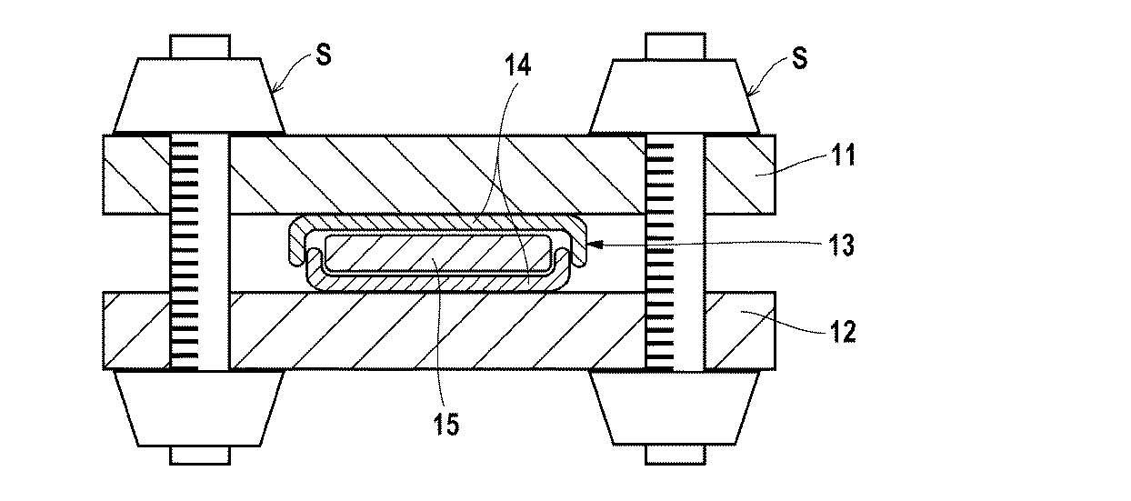
[参考例3] 固体電解質シートの作製
上記固体電解質組成物(S−1)を厚み20μmのアルミ箔上に、クリアランスが調節可能なアプリケーターにより塗布し、80℃で1時間加熱した後、さらに120℃で1時間加熱し、(e1)の分散媒体を乾燥させた。その後、ヒートプレス機を用いて、加熱(80℃)しながら加圧し(10MPa、1分間)、試料No.101の固体電解質シートを得た。
固体電解質組成物(S−1)を上記表1に示す各固体電解質組成物(S−2)〜(S−14)、(T−1)、(T−2)に変更した以外は、試料No.101の固体電解質シートと同様にして、試料No.102〜114およびc11及び12の固体電解質シートを作製した。なお、c12の作製に際しては、乾燥を60℃で10分間のみとし、アセトンを揮発させ、DMCを一定量残存させた。
試料No.101〜114及びc11の固体電解質層の膜厚は50μmであった。また、試料No.c12の固体電解質層の膜厚は200μmであった。
Reference Example 3 Production of Solid Electrolyte Sheet The solid electrolyte composition (S-1) was applied onto an aluminum foil having a thickness of 20 μm using an applicator with adjustable clearance, heated at 80 ° C. for 1 hour, and then further 120 The dispersion medium of (e1) was dried by heating at 0 ° C. for 1 hour. Then, using a heat press machine, it pressurized (10 MPa, 1 minute), heating (80 degreeC). 101 solid electrolyte sheet was obtained.
Except for changing the solid electrolyte composition (S-1) to the solid electrolyte compositions (S-2) to (S-14), (T-1), and (T-2) shown in Table 1 above, the sample No. In the same manner as the solid electrolyte sheet of No. 101, Sample No. Solid electrolyte sheets of 102 to 114 and c11 and 12 were produced. In preparing c12, drying was performed only at 60 ° C. for 10 minutes, and acetone was volatilized to leave a certain amount of DMC.
Sample No. The film thicknesses of the solid electrolyte layers 101 to 114 and c11 were 50 μm. Sample No. The film thickness of the solid electrolyte layer of c12 was 200 μm.
上記で作製した各固体電解質シートを用いて、結着性、イオン伝導度および引火性を評価した。 Using each of the solid electrolyte sheets prepared above, binding properties, ionic conductivity, and flammability were evaluated.
[試験例1] 結着性の評価
上記で作製した固体電解質シートの固体電解質層を縦50mm、横12mmの矩形状に切り出し、幅12mm、長さ60mmのセロテープ(登録商標、ニチバン社製)を貼り、10mm/minの速度で50mm引き剥がした。その際の、引き剥がしたセロテープの面積に対する剥離したシート部分の面積比率で評価した。同一処方で作製した10個の試料について測定し(すなわち計10回測定し)、最大値および最小値を除いた、8回の測定値の平均を採用した。
得られた値を、下記評価基準に基づき評価した。結果を下表に示す。
[Test Example 1] Evaluation of binding property The solid electrolyte layer of the solid electrolyte sheet produced above was cut into a rectangular shape having a length of 50 mm and a width of 12 mm, and a cello tape (registered trademark, manufactured by Nichiban Co., Ltd.) having a width of 12 mm and a length of 60 mm was used. The film was peeled off by 50 mm at a speed of 10 mm / min. In that case, it evaluated by the area ratio of the sheet | seat part which peeled with respect to the area of the peeled-off cellotape. Measurement was performed on 10 samples prepared with the same formulation (that is, a total of 10 measurements), and an average of 8 measurement values excluding the maximum value and the minimum value was adopted.
The obtained value was evaluated based on the following evaluation criteria. The results are shown in the table below.
(評価基準)
4: 剥離したシート部分の面積比率が5%以上15%未満
3: 剥離したシート部分の面積比率が15%以上30%未満
2: 剥離したシート部分の面積比率が30%以上60%未満
1: 剥離したシート部分の面積比率が60%以上
(Evaluation criteria)
4: The area ratio of the peeled sheet part is 5% or more and less than 15% 3: The area ratio of the peeled sheet part is 15% or more and less than 30% 2: The area ratio of the peeled sheet part is 30% or more and less than 60% 1: The area ratio of the peeled sheet part is 60% or more
[試験例2] イオン伝導性の評価
上記で作製した各固体電解質シートを直径14.5mmの円板状に切り出し、直径15mmの円板状に切り出したアルミ箔を固体電解質層と接触させ、スペーサーとワッシャーを組み込んで、ステンレス製の2032型コインケースに入れた。図2に示すように、コインケースの外部から拘束圧(ネジ締め圧:8N)をかけ、イオン伝導度測定用セルを作製した。
[Test Example 2] Evaluation of ion conductivity Each solid electrolyte sheet prepared above was cut into a disk shape having a diameter of 14.5 mm, and the aluminum foil cut into a disk shape having a diameter of 15 mm was brought into contact with the solid electrolyte layer, and spacers were formed. And washer was put into a stainless steel 2032 type coin case. As shown in FIG. 2, a binding pressure (screw tightening pressure: 8N) was applied from the outside of the coin case to produce an ion conductivity measurement cell.
上記で得られた各イオン伝導度測定用セルを用いて、イオン伝導度を測定した。具体的には、30℃の恒温槽中、SOLARTRON社製 1255B FREQUENCY RESPONSE ANALYZER(商品名)を用いて電圧振幅を5mVとし、周波数1MHz〜1Hzまで交流インピーダンス測定した。これにより試料の膜厚方向の抵抗を求め、下記計算式によりイオン伝導度を求めた。結果を下表に示す。
イオン伝導度(mS/cm)=
1000×試料膜厚(cm)/(抵抗(Ω)×試料面積(cm2))
The ion conductivity was measured using each ion conductivity measurement cell obtained above. Specifically, in a constant temperature bath at 30 ° C., AC impedance was measured from 1 MHz to 1 Hz with a voltage amplitude of 5 mV using 1255B FREQUENCY RESPONSE ANALYZER (trade name) manufactured by SOLARTRON. Thereby, the resistance in the film thickness direction of the sample was obtained, and the ionic conductivity was obtained by the following formula. The results are shown in the table below.
Ionic conductivity (mS / cm) =
1000 × sample film thickness (cm) / (resistance (Ω) × sample area (cm 2 ))
[試験例3] 引火性の評価
上記で作製した各固体電解質シートの固体電解質層に、全炎長2cmに調整したブタンガスバーナーの内炎を3秒間接触させ、炎を離した後の固体電解質層の引火の有無に基づき、引火性を評価した。
[Test Example 3] Evaluation of flammability The solid electrolyte layer of each solid electrolyte sheet produced as described above was brought into contact with the internal flame of a butane gas burner adjusted to a total flame length of 2 cm for 3 seconds, and the flame was released. Flammability was evaluated based on the presence or absence of flammability.
表2に示されるように、固体電解質層が成分(a)及び(b)を含有しない試料c11の固体電解質シートは、固体電解質粒子間の結着性に劣る結果となり、イオン伝導性も検出できなかった。また、固体電解質層中に成分(b)以外の溶媒を多量に含む試料c12では、固体電解質層は引火性を有し、安全性に劣る結果となった。
これに対し、固体電解質層が本発明の規定(a)〜(d)を満たす試料101〜114は、固体電解質粒子間の結着性が良好で、優れたイオン伝導度を示した。
As shown in Table 2, the solid electrolyte sheet of sample c11 in which the solid electrolyte layer does not contain components (a) and (b) results in inferior binding between the solid electrolyte particles, and ion conductivity can also be detected. There wasn't. In sample c12 containing a large amount of a solvent other than component (b) in the solid electrolyte layer, the solid electrolyte layer was flammable, resulting in poor safety.
On the other hand, the samples 101 to 114 in which the solid electrolyte layer satisfies the provisions (a) to (d) of the present invention have good binding properties between the solid electrolyte particles and exhibited excellent ionic conductivity.
[実施例、比較例] 全固体二次電池用電極シートの製造
全固体二次電池用電極シートおよび全固体二次電池を下記の通り作製した。
[Example, Comparative Example] Production of electrode sheet for all-solid-state secondary battery An electrode sheet for all-solid-state secondary battery and an all-solid-state secondary battery were produced as follows.
<正極用組成物の調製>
ジルコニア製45mL容器(フリッチュ社製)に、直径5mmのジルコニアビーズを180個投入し、正極活物質のNMCを6質量部、(a1)のLiTFSIを0.45質量部、(b1)の高沸点溶媒としてプロピレンカーボネートを0.09質量部、(c1)の無機固体電解質としてLLZ(Li7La3Zr2O12 ランタンジルコン酸リチウム、体積平均粒子径5.06μm、豊島製作所社製)を4質量部、(e1)の低沸点溶媒(分散媒体)としてジメチルカーボネートを18.0g投入した。その後、フリッチュ社製遊星ボールミルに上記の容器をセットし、回転数100rpmで1時間混合し、下表に示す試料No.201に用いる正極用組成物を調製した。
用いる正極活物質及び固体電解質の種類並びにプロピレンカーボネートの使用量を下表に示す通りに変更したこと以外は上記と同様にして、下表に示す試料No.202〜206、c21及び22に用いる正極用組成物を調製した。なお、試料No.c21に対応する正極用組成物にはLiTFSIとプロピレンカーボネートを配合していない。
<Preparation of composition for positive electrode>
180 pieces of zirconia beads having a diameter of 5 mm are put into a 45 mL container (manufactured by Fritsch) made of zirconia, 6 parts by mass of the positive electrode active material NMC, 0.45 parts by mass of LiTFSI of (a1), and high boiling point of (b1) 0.09 parts by mass of propylene carbonate as a solvent, and 4 masses of LLZ (Li 7 La 3 Zr 2 O 12 lithium lanthanum zirconate, volume average particle size 5.06 μm, manufactured by Toshima Seisakusho Co., Ltd.) as the inorganic solid electrolyte of (c1) Part, 18.0 g of dimethyl carbonate was added as a low boiling point solvent (dispersion medium) of (e1). Thereafter, the above container was set on a planetary ball mill manufactured by Fritsch, and mixed for 1 hour at a rotational speed of 100 rpm. The composition for positive electrodes used for 201 was prepared.
Sample No. shown in the following table was the same as above except that the type of the positive electrode active material and solid electrolyte used and the amount of propylene carbonate used were changed as shown in the following table. The composition for positive electrodes used for 202-206, c21, and 22 was prepared. Sample No. LiTFSI and propylene carbonate are not blended in the positive electrode composition corresponding to c21.
<負極用組成物の調製>
ジルコニア製45mL容器(フリッチュ社製)に、直径5mmのジルコニアビーズを180個投入し、負極活物質の黒鉛を6質量部、(a1)の金属塩としてLiTFSIを0.45質量部、(b1)の高沸点溶媒としてプロピレンカーボネートを0.09質量部、(c1)の無機固体電解質としてLLZ(Li7La3Zr2O12 ランタンジルコン酸リチウム、体積平均粒子径5.06μm、豊島製作所社製)を4質量部、(e1)の低沸点溶媒(分散媒体)としてジメチルカーボネートを18.0g投入した。その後、フリッチュ社製遊星ボールミルに上記の容器をセットし、回転数100rpmで1時間混合し、下表に示す試料No.201に用いる負極用組成物を調製した。
用いる負極活物質及び固体電解質の種類並びにプロピレンカーボネートの使用量を下表に示す通りに変更したこと以外は上記と同様にして、下表に示す試料No.202〜206、c21及び22に用いる負極用組成物を調製した。なお、試料No.c21に対応する負極用組成物にはLiTFSIとプロピレンカーボネートを配合していない。
下表に記載の略称について以下に説明する。
・NMC:Li(Ni1/3Mn1/3Co1/3)O2 ニッケル、マンガン、コバルト酸リチウム
・LCO:LiCoO2 コバルト酸リチウム
・LTO:Li4Ti5O12
<Preparation of negative electrode composition>
180 pieces of zirconia beads having a diameter of 5 mm are put into a 45 mL container (made by Fritsch) made of zirconia, 6 parts by mass of graphite as a negative electrode active material, 0.45 parts by mass of LiTFSI as a metal salt of (a1), (b1) 0.09 parts by mass of propylene carbonate as a high boiling point solvent, and LLZ (Li 7 La 3 Zr 2 O 12 lithium lanthanum zirconate, volume average particle size 5.06 μm, manufactured by Toyoshima Seisakusho) as an inorganic solid electrolyte of (c1) 4 parts by mass, 18.0 g of dimethyl carbonate was added as a low boiling point solvent (dispersion medium) of (e1). Thereafter, the above container was set on a planetary ball mill manufactured by Fritsch, and mixed for 1 hour at a rotational speed of 100 rpm. A negative electrode composition used for 201 was prepared.
In the same manner as described above except that the type of the negative electrode active material and the solid electrolyte used and the amount of propylene carbonate used were changed as shown in the table below, Sample No. Negative electrode compositions used for 202 to 206, c21 and 22 were prepared. Sample No. LiTFSI and propylene carbonate are not blended in the negative electrode composition corresponding to c21.
The abbreviations listed in the table below are described below.
NMC: Li (Ni 1/3 Mn 1/3 Co 1/3 ) O 2 nickel, manganese, lithium cobaltate LCO: LiCoO 2 lithium cobaltate LTO: Li 4 Ti 5 O 12
<全固体二次電池用電極シートの作製>
上記で得られた各正極用組成物を、厚み20μmのアルミ箔上に、アプリケーターにより塗布し、120℃で2時間乾燥し、(e1)の分散媒体を揮発、除去した。その後、ヒートプレス機を用いて、加熱(80℃)しながら加圧した(10Pa、1分間)。こうして、下表に示す試料No.201〜206及びc21に対応する正極活物質層を形成し、正極集電体と正極活物質層からなる2層積層構造の各電極シートを作製した。各2層積層構造の電極シートにおいて正極活物質層の厚さはいずれも150μmであった。
また、試料No.c22に対応する正極活物質層については、上記正極活物質層の形成において、120℃、2時間の乾燥を60℃、10分間に変更し、また、ヒートプレス機による加熱、加圧は実施しなかった。すなわち試料No.c22に対応する正極層にはDMCを残存させた。試料No.c22に対応する正極活物質層の厚さは180μmであった。
<Preparation of electrode sheet for all-solid-state secondary battery>
Each positive electrode composition obtained above was applied onto an aluminum foil having a thickness of 20 μm by an applicator and dried at 120 ° C. for 2 hours to volatilize and remove the dispersion medium of (e1). Then, it pressurized (10 Pa, 1 minute), heating (80 degreeC) using the heat press machine. Thus, the sample No. shown in the table below. The positive electrode active material layer corresponding to 201-206 and c21 was formed, and each electrode sheet of the two-layer laminated structure which consists of a positive electrode collector and a positive electrode active material layer was produced. In each two-layer electrode sheet, the thickness of the positive electrode active material layer was 150 μm.
Sample No. For the positive electrode active material layer corresponding to c22, in the formation of the positive electrode active material layer, drying at 120 ° C. for 2 hours was changed to 60 ° C. for 10 minutes, and heating and pressurization with a heat press machine were performed. There wasn't. That is, sample no. DMC was left in the positive electrode layer corresponding to c22. Sample No. The thickness of the positive electrode active material layer corresponding to c22 was 180 μm.
上記で作製した各2層積層体電極シートの正極活物質層上に、上記参考例2で調製した、下表に示す固体電解質組成物を、アプリケーターにより塗布した。その後120℃で2時間乾燥し、(e1)の分散媒体を揮発、除去した。こうして、下表に示す試料No.201〜206及びc21に対応する、正極集電体と正極活物質層と固体電解質層からなる3層積層構造の電極シートを作製した。
また、試料No.c22に対応する固体電解質層については、上記3層積層構造の電極シートの作製において、120℃、2時間の乾燥を60℃、10分間に変更してアセトンを揮発させた。すなわち試料No.c22に対応する固体電解質層にはDMCが残存している。
On the positive electrode active material layer of each of the two-layer laminate electrode sheets prepared above, the solid electrolyte composition shown in the following table, which was prepared in Reference Example 2, was applied using an applicator. Thereafter, drying was performed at 120 ° C. for 2 hours, and the dispersion medium (e1) was volatilized and removed. Thus, the sample No. shown in the table below. An electrode sheet having a three-layer structure composed of a positive electrode current collector, a positive electrode active material layer, and a solid electrolyte layer corresponding to 201 to 206 and c21 was produced.
Sample No. For the solid electrolyte layer corresponding to c22, acetone was volatilized by changing the drying at 120 ° C. for 2 hours to 60 ° C. for 10 minutes in the preparation of the electrode sheet having the above three-layer structure. That is, sample no. DMC remains in the solid electrolyte layer corresponding to c22.
上記で作製した各3層積層構造の電極シートの固体電解質層上に、上記で調製した負極用組成物を塗布し、120℃で2時間乾燥し、(e1)の分散媒体を揮発、除去した。その後、ヒートプレス機を用いて、加熱(80℃)しながら加圧した(10MPa、1分間)。こうして、下表に示す試料No.201〜206及びc21に対応する、正極集電体と正極活物質層と固体電解質層と負極活物質層からなる4層積層構造の電極シートを作製した。
また、試料No.c22に対応する負極層の形成については、上記3層積層構造の電極シートの作製において、120℃、2時間の乾燥を60℃、10分間に変更し、また、ヒートプレス機による加熱、加圧は実施しなかった。すなわち試料No.c22に対応する負極層にはDMCが残存している。得られた4層積層構造の電極シートにおいて、固体電解質組成物層の厚さは、試料No.201〜206及びc21に対応する固体電解質組成物層がいずれも50μmであり、試料No.c22に対応する固体電解質組成物層が200μmであった。また、負極活物質層の厚さは、試料No.201〜206及びc21に対応する負極活物質層がいずれも120μmであり、試料No.c22に対応する負極活物質層が140μmであった。
The negative electrode composition prepared above was applied onto the solid electrolyte layer of each of the three-layered electrode sheets prepared above, dried at 120 ° C. for 2 hours, and the dispersion medium (e1) was volatilized and removed. . Then, it pressurized (10 MPa, 1 minute), heating (80 degreeC) using the heat press machine. Thus, the sample No. shown in the table below. Electrode sheets having a four-layer structure composed of a positive electrode current collector, a positive electrode active material layer, a solid electrolyte layer, and a negative electrode active material layer corresponding to 201 to 206 and c21 were produced.
Sample No. Regarding the formation of the negative electrode layer corresponding to c22, in the production of the electrode sheet having the above three-layer structure, the drying at 120 ° C. for 2 hours was changed to 60 ° C. for 10 minutes, and heating and pressurization with a heat press machine were performed. Was not implemented. That is, sample no. DMC remains in the negative electrode layer corresponding to c22. In the obtained electrode sheet having a four-layer laminated structure, the thickness of the solid electrolyte composition layer was measured according to Sample No. Each of the solid electrolyte composition layers corresponding to 201 to 206 and c21 is 50 μm. The solid electrolyte composition layer corresponding to c22 was 200 μm. The thickness of the negative electrode active material layer is the same as that of Sample No. The negative electrode active material layers corresponding to 201 to 206 and c21 are all 120 μm. The negative electrode active material layer corresponding to c22 was 140 μm.
上記で作製した4層積層構造の電極シートを用いて、結着性、イオン伝導性及び引火性を評価した。 Using the electrode sheet having a four-layer structure produced as described above, binding property, ion conductivity and flammability were evaluated.
[試験例4] 結着性の評価
上記試験例1において、セロテープを貼り付ける対象を、上記4層積層構造の電極シートの負極活物質層に変更した以外は試験例1と同様にして、結着性を評価した。結果を下表に示す。
[Test Example 4] Evaluation of Bindability In Test Example 1, the same procedure as in Test Example 1 was conducted, except that the object to which the cellophane was applied was changed to the negative electrode active material layer of the electrode sheet having the four-layer laminated structure. Wearability was evaluated. The results are shown in the table below.
[試験例5] イオン伝導性の評価
上記で作製した4層積層構造の電極シートを直径14.5mmの円板状に切り出し、直径15mmの円盤状に切り出した厚み20μmの銅箔を負極活物質層上に接触させ、スペーサーとワッシャーを組み込んで、ステンレス製の2032型コインケースに入れ、全固体二次電池を作製した。コインケースの外部から拘束圧(ネジ締め圧:8N)をかけ、イオン伝導度測定用全固体二次電池を作製した。このイオン伝導度測定用全固体二次電池を用いて、試験例2と同様にしてイオン伝導度を測定した。結果を下表に示す。
[Test Example 5] Evaluation of ion conductivity The electrode sheet having the four-layer structure prepared above was cut into a disk shape having a diameter of 14.5 mm, and a copper foil having a thickness of 20 μm cut into a disk shape having a diameter of 15 mm was used as a negative electrode active material. The all-solid-state secondary battery was manufactured by contacting the top of the layer, incorporating a spacer and washer, and placing it in a stainless steel 2032 type coin case. A constraining pressure (screw tightening pressure: 8N) was applied from the outside of the coin case to produce an all-solid secondary battery for ion conductivity measurement. Using this all solid state secondary battery for ion conductivity measurement, the ion conductivity was measured in the same manner as in Test Example 2. The results are shown in the table below.
[試験例6] 引火性の評価
上記で作製した4層積層構造の電極シートの負極活物質層に、全炎長2cmに調整したブタンガスバーナーの内炎を3秒間接触させ、炎を離した後の負極活物質層の引火の有無に基づき、引火性を評価した。結果を下表に示す。
[Test Example 6] Evaluation of flammability After the inner flame of a butane gas burner adjusted to a total flame length of 2 cm was brought into contact with the negative electrode active material layer of the electrode sheet having a four-layer structure prepared above for 3 seconds, and the flame was released. The flammability was evaluated based on the presence or absence of ignition of the negative electrode active material layer. The results are shown in the table below.
上記表3に示される通り、電極層及び固体電解質層が本発明で規定する(a)〜(d)を満たす電極シートは、固体電解質ないし活物質が層中で良好な結着性を示し、この電極シートを用いて作製した全固体二次電池は優れたイオン伝導性を示すことがわかった。また、電極層が本発明で規定する(a)〜(d)を満たす電極シートは、引火せず、安全性にも優れていた。 As shown in Table 3 above, the electrode sheet satisfying (a) to (d) defined in the present invention by the electrode layer and the solid electrolyte layer has good binding properties in the layer of the solid electrolyte or active material, It turned out that the all-solid-state secondary battery produced using this electrode sheet shows the outstanding ion conductivity. Moreover, the electrode sheet which satisfies (a)-(d) which an electrode layer prescribes | regulates by this invention did not ignite, and was excellent also in safety.
1 負極集電体
2 負極活物質層
3 固体電解質層
4 正極活物質層
5 正極集電体
6 作動部位
10 全固体二次電池
11 上部支持板
12 下部支持板
13 コイン電池
14 コインケース
15 全固体二次電池用電極シート
S ネジ
DESCRIPTION OF SYMBOLS 1
Claims (4)
(a1)周期律表第1族又は第2族に属する金属の塩であって、イオン伝導性を有する金属塩を含有する。
(b1)沸点150〜300℃の溶媒を含有し、前記組成物固形分中、沸点150〜300℃の溶媒の含有量が0.2〜10質量%である。
(c1)周期律表第1族又は第2族に属する金属のイオンの伝導性を有する無機固体電解質を含有する。
(d1)前記(b1)の溶媒の含有量に対する前記(a1)の金属塩の含有量の比が、モル比で、[金属塩の含有量]/[溶媒の含有量]=1.0/0.1〜1.0/5.0である。
(e1)沸点120℃未満の溶媒を含有し、前記組成物中、沸点120℃未満の溶媒の含有量が20〜80質量%である。 A method for producing an all-solid secondary battery having a negative electrode active material layer, a solid electrolyte layer, and a positive electrode active material layer in this order, wherein a composition satisfying the following (a1) to (e1) is applied on a metal foil, A method for producing an all-solid secondary battery, comprising: drying and volatilizing a solvent having a boiling point of less than 120 ° C. to form at least one of the negative electrode active material layer, the solid electrolyte layer, and the positive electrode active material layer. .
(A1) A metal salt belonging to Group 1 or Group 2 of the Periodic Table and containing a metal salt having ionic conductivity.
(B1) A solvent having a boiling point of 150 to 300 ° C. is contained, and the content of the solvent having a boiling point of 150 to 300 ° C. is 0.2 to 10% by mass in the solid content of the composition.
(C1) An inorganic solid electrolyte having conductivity of ions of metals belonging to Group 1 or Group 2 of the periodic table is contained.
(D1) The ratio of the content of the metal salt of (a1) to the content of the solvent of (b1) is a molar ratio of [content of metal salt] / [content of solvent] = 1.0 / 0.1-1.0 / 5.0.
(E1) A solvent having a boiling point of less than 120 ° C. is contained, and the content of the solvent having a boiling point of less than 120 ° C. is 20 to 80% by mass in the composition.
(a1)周期律表第1族又は第2族に属する金属の塩であって、イオン伝導性を有する金属塩を含有する。
(b1)沸点150〜300℃の溶媒を含有し、前記組成物固形分中、沸点150〜300℃の溶媒の含有量が0.2〜10質量%である。
(c1)周期律表第1族又は第2族に属する金属のイオンの伝導性を有する無機固体電解質を含有する。
(d1)前記(b1)の溶媒の含有量に対する前記(a1)の金属塩の含有量の比が、モル比で、[金属塩の含有量]/[溶媒の含有量]=1.0/0.1〜1.0/5.0である。
(e1)沸点120℃未満の溶媒を含有し、前記組成物中、沸点120℃未満の溶媒の含有量が20〜80質量%である。 The manufacturing method of the electrode sheet for all-solid-state secondary batteries including apply | coating the composition which satisfy | fills following (a1)-(e1) on metal foil, and drying and volatilizing the solvent below boiling point 120 degreeC.
(A1) A metal salt belonging to Group 1 or Group 2 of the Periodic Table and containing a metal salt having ionic conductivity.
(B1) A solvent having a boiling point of 150 to 300 ° C. is contained, and the content of the solvent having a boiling point of 150 to 300 ° C. is 0.2 to 10% by mass in the solid content of the composition.
(C1) An inorganic solid electrolyte having conductivity of ions of metals belonging to Group 1 or Group 2 of the periodic table is contained.
(D1) The ratio of the content of the metal salt of (a1) to the content of the solvent of (b1) is a molar ratio of [content of metal salt] / [content of solvent] = 1.0 / 0.1-1.0 / 5.0.
(E1) A solvent having a boiling point of less than 120 ° C. is contained, and the content of the solvent having a boiling point of less than 120 ° C. is 20 to 80% by mass in the composition.
(a1)周期律表第1族又は第2族に属する金属の塩であって、イオン伝導性を有する金属塩を含有する。
(b1)沸点150〜300℃の溶媒を含有し、前記組成物固形分中、沸点150〜300℃の溶媒の含有量が0.2〜10質量%である。
(c1)周期律表第1族又は第2族に属する金属のイオンの伝導性を有する無機固体電解質を含有する。
(d1)前記(b1)の溶媒の含有量に対する前記(a1)の金属塩の含有量の比が、モル比で、[金属塩の含有量]/[溶媒の含有量]=1.0/0.1〜1.0/5.0である。
(e1)沸点120℃未満の溶媒を含有し、前記組成物中、沸点120℃未満の溶媒の含有量が20〜80質量%である。 An all-solid secondary battery composition that satisfies the following (a1) to (e1).
(A1) A metal salt belonging to Group 1 or Group 2 of the Periodic Table and containing a metal salt having ionic conductivity.
(B1) A solvent having a boiling point of 150 to 300 ° C. is contained, and the content of the solvent having a boiling point of 150 to 300 ° C. is 0.2 to 10% by mass in the solid content of the composition.
(C1) An inorganic solid electrolyte having conductivity of ions of metals belonging to Group 1 or Group 2 of the periodic table is contained.
(D1) The ratio of the content of the metal salt of (a1) to the content of the solvent of (b1) is a molar ratio of [content of metal salt] / [content of solvent] = 1.0 / 0.1-1.0 / 5.0.
(E1) A solvent having a boiling point of less than 120 ° C. is contained, and the content of the solvent having a boiling point of less than 120 ° C. is 20 to 80% by mass in the composition.
(a)周期律表第1族又は第2族に属する金属の塩であって、イオン伝導性を有する金属塩を含有する。
(b)沸点150〜300℃の溶媒を0.2〜10質量%含有する。
(c)周期律表第1族又は第2族に属する金属のイオンの伝導性を有する無機固体電解質を含有する。
(d)前記(b)の溶媒の含有量に対する前記(a)の金属塩の含有量の比が、モル比で、[金属塩の含有量]/[溶媒の含有量]=1.0/0.1〜1.0/5.0である。
The composition for an all-solid-state secondary battery according to claim 3 , which is used for forming a layer satisfying the following (a) to (d).
(A) A metal salt belonging to Group 1 or Group 2 of the Periodic Table and containing a metal salt having ionic conductivity.
(B) 0.2-10 mass% of solvent with a boiling point of 150-300 degreeC is contained.
(C) It contains an inorganic solid electrolyte having conductivity of metal ions belonging to Group 1 or Group 2 of the Periodic Table.
(D) The ratio of the content of the metal salt of (a) to the content of the solvent of (b) is a molar ratio of [content of metal salt] / [content of solvent] = 1.0 / 0.1-1.0 / 5.0.
Priority Applications (1)
| Application Number | Priority Date | Filing Date | Title |
|---|---|---|---|
| JP2015166955A JP6572063B2 (en) | 2015-08-26 | 2015-08-26 | All-solid-state secondary battery, electrode sheet for all-solid-state secondary battery, and production method thereof |
Applications Claiming Priority (1)
| Application Number | Priority Date | Filing Date | Title |
|---|---|---|---|
| JP2015166955A JP6572063B2 (en) | 2015-08-26 | 2015-08-26 | All-solid-state secondary battery, electrode sheet for all-solid-state secondary battery, and production method thereof |
Publications (2)
| Publication Number | Publication Date |
|---|---|
| JP2017045611A JP2017045611A (en) | 2017-03-02 |
| JP6572063B2 true JP6572063B2 (en) | 2019-09-04 |
Family
ID=58211534
Family Applications (1)
| Application Number | Title | Priority Date | Filing Date |
|---|---|---|---|
| JP2015166955A Active JP6572063B2 (en) | 2015-08-26 | 2015-08-26 | All-solid-state secondary battery, electrode sheet for all-solid-state secondary battery, and production method thereof |
Country Status (1)
| Country | Link |
|---|---|
| JP (1) | JP6572063B2 (en) |
Families Citing this family (7)
| Publication number | Priority date | Publication date | Assignee | Title |
|---|---|---|---|---|
| WO2018168505A1 (en) * | 2017-03-14 | 2018-09-20 | 富士フイルム株式会社 | Solid electrolyte composition, solid electrolyte-containing sheet, all-solid-state secondary battery, method for producing solid electrolyte composition, method for producing solid electrolyte-containing sheet, and method for producing all-solid-state secondary battery |
| JP7183529B2 (en) * | 2017-05-30 | 2022-12-06 | 凸版印刷株式会社 | LAMINATED GREEN SHEET, ALL-SOLID SECONDARY BATTERY AND MANUFACTURING METHOD THEREOF |
| JP6972965B2 (en) * | 2017-11-27 | 2021-11-24 | トヨタ自動車株式会社 | All solid state battery |
| JP6915744B2 (en) * | 2018-03-30 | 2021-08-04 | 富士通株式会社 | Resistance change element and its manufacturing method, storage device |
| WO2023234350A1 (en) * | 2022-06-01 | 2023-12-07 | 富士フイルム株式会社 | Wound all-solid-state lithium ion secondary battery and method for producing wound all-solid-state lithium ion secondary battery |
| WO2024046966A1 (en) | 2022-08-30 | 2024-03-07 | Arlanxeo Deutschland Gmbh | HNBR CATHODE BINDERS FOR BATTERY CELLS USING γ-VALEROLACTONE AS PROCESSING SOLVENT |
| WO2024052261A1 (en) | 2022-09-06 | 2024-03-14 | Arlanxeo Deutschland Gmbh | EVM cathode binders for battery cells using γ-valerolactone as processing solvent |
Family Cites Families (5)
| Publication number | Priority date | Publication date | Assignee | Title |
|---|---|---|---|---|
| US6544689B1 (en) * | 1999-06-30 | 2003-04-08 | North Carolina State University | Composite electrolytes based on smectite clays and high dielectric organic liquids and electrodes |
| JP2009289534A (en) * | 2008-05-28 | 2009-12-10 | Idemitsu Kosan Co Ltd | Electrode for all-solid lithium battery, all-solid lithium battery and apparatus |
| JP2011065982A (en) * | 2009-08-18 | 2011-03-31 | Seiko Epson Corp | Lithium battery electrode body and lithium battery |
| CN103081209B (en) * | 2011-04-11 | 2016-08-10 | 松下知识产权经营株式会社 | Thin battery and cell apparatus |
| JP6111895B2 (en) * | 2012-06-28 | 2017-04-12 | 日本ゼオン株式会社 | Slurry composition for negative electrode of lithium ion secondary battery, negative electrode for secondary battery and secondary battery |
-
2015
- 2015-08-26 JP JP2015166955A patent/JP6572063B2/en active Active
Also Published As
| Publication number | Publication date |
|---|---|
| JP2017045611A (en) | 2017-03-02 |
Similar Documents
| Publication | Publication Date | Title |
|---|---|---|
| JP6721669B2 (en) | Solid electrolyte composition, electrode sheet for all solid state secondary battery and all solid state secondary battery, and electrode sheet for all solid state secondary battery and method for manufacturing all solid state secondary battery | |
| JP6452814B2 (en) | Material for positive electrode, electrode sheet for all-solid-state secondary battery, all-solid-state secondary battery, electrode sheet for all-solid-state secondary battery, and method for producing all-solid-state secondary battery | |
| JP6572063B2 (en) | All-solid-state secondary battery, electrode sheet for all-solid-state secondary battery, and production method thereof | |
| JP6665284B2 (en) | Solid electrolyte composition, solid electrolyte-containing sheet and all-solid secondary battery, and method for producing solid electrolyte-containing sheet and all-solid secondary battery | |
| WO2019188487A1 (en) | Fully solid-state secondary battery and method of manufacturing same | |
| JP6684901B2 (en) | Solid electrolyte composition, solid electrolyte-containing sheet and all solid state secondary battery, and method for producing solid electrolyte containing sheet and all solid state secondary battery | |
| WO2018047946A1 (en) | Electrode layer material, sheet for all-solid-state secondary battery electrode, all-solid-state secondary battery, electrode sheet for all-solid-state secondary battery, and method for producing all-solid-state secondary battery | |
| JP6621532B2 (en) | SOLID ELECTROLYTE COMPOSITION, SOLID ELECTROLYTE-CONTAINING SHEET, ELECTRODE SHEET FOR ALL-SOLID SECONDARY BATTERY AND ALL-SOLID SECONDARY BATTERY, AND SOLID ELECTROLYTE-CONTAINING SHEET, ELECTRODE SHEET FOR ALL-SOLID SECONDARY BATTERY | |
| WO2018168505A1 (en) | Solid electrolyte composition, solid electrolyte-containing sheet, all-solid-state secondary battery, method for producing solid electrolyte composition, method for producing solid electrolyte-containing sheet, and method for producing all-solid-state secondary battery | |
| JPWO2016017759A1 (en) | All-solid secondary battery, solid electrolyte composition, battery electrode sheet using the same, battery electrode sheet manufacturing method, and all-solid secondary battery manufacturing method | |
| WO2019097906A1 (en) | Solid electrolyte composition, solid-electrolyte-containing sheet, all-solid-state secondary battery electrode sheet, all-solid-state secondary battery, production method for solid-electrode-containing sheet, and production method for all-solid-state secondary battery | |
| JP7059302B2 (en) | A method for producing a solid electrolyte composition, a solid electrolyte-containing sheet and an all-solid-state secondary battery, and a solid electrolyte-containing sheet and an all-solid-state secondary battery. | |
| JP7008080B2 (en) | Method for manufacturing solid electrolyte composition, solid electrolyte-containing sheet and all-solid-state secondary battery, and solid electrolyte-containing sheet and all-solid-state secondary battery | |
| WO2020059550A1 (en) | Production method for all-solid secondary battery layered member, and production method for all-solid secondary battery | |
| WO2019087750A1 (en) | Composition for forming active material layer, method for preparing same, electrode sheet for all-solid secondary battery, and method for manufacturing all-solid secondary battery | |
| JP6665343B2 (en) | Inorganic solid electrolyte material, and slurry using the same, solid electrolyte membrane for all solid secondary battery, solid electrolyte sheet for all solid secondary battery, positive electrode active material membrane for all solid secondary battery, for all solid secondary battery Negative electrode active material film, electrode sheet for all-solid secondary battery, all-solid secondary battery, and method for manufacturing all-solid secondary battery | |
| JP2017162597A (en) | Electrode material, electrode sheet for all-solid-state secondary battery and all-solid-state secondary battery using the electrode material, and method of manufacturing electrode sheet for all-solid-state secondary battery and all-solid-state secondary battery | |
| JP6673785B2 (en) | Solid electrolyte composition, solid electrolyte-containing sheet and all-solid secondary battery, and method for producing solid electrolyte-containing sheet and all-solid secondary battery | |
| JP6623083B2 (en) | Solid electrolyte composition, sheet for all-solid secondary battery and all-solid-state secondary battery using the same, and method for producing them | |
| US12040445B2 (en) | Solid electrolyte composition, solid electrolyte-containing sheet, all-solid state secondary battery, and methods for manufacturing solid electrolyte-containing sheet and all-solid state secondary battery | |
| WO2020067108A1 (en) | Composition for negative electrodes of all-solid-state secondary batteries, negative electrode sheet for all-solid-state secondary batteries, all-solid-state secondary battery, method for producing negative electrode sheet for all-solid-state secondary batteries, and method for producing all-solid-state secondary battery | |
| WO2020067002A1 (en) | Negative electrode composition, negative electrode sheet for solid-state secondary battery, solid-state secondary battery, and method for producing solid-state secondary battery negative electrode sheet or solid-state secondary battery |
Legal Events
| Date | Code | Title | Description |
|---|---|---|---|
| A621 | Written request for application examination |
Free format text: JAPANESE INTERMEDIATE CODE: A621 Effective date: 20170804 |
|
| A977 | Report on retrieval |
Free format text: JAPANESE INTERMEDIATE CODE: A971007 Effective date: 20180516 |
|
| A131 | Notification of reasons for refusal |
Free format text: JAPANESE INTERMEDIATE CODE: A131 Effective date: 20180710 |
|
| A521 | Request for written amendment filed |
Free format text: JAPANESE INTERMEDIATE CODE: A523 Effective date: 20180907 |
|
| RD02 | Notification of acceptance of power of attorney |
Free format text: JAPANESE INTERMEDIATE CODE: A7422 Effective date: 20180907 |
|
| A131 | Notification of reasons for refusal |
Free format text: JAPANESE INTERMEDIATE CODE: A131 Effective date: 20190305 |
|
| A521 | Request for written amendment filed |
Free format text: JAPANESE INTERMEDIATE CODE: A523 Effective date: 20190426 |
|
| TRDD | Decision of grant or rejection written | ||
| A01 | Written decision to grant a patent or to grant a registration (utility model) |
Free format text: JAPANESE INTERMEDIATE CODE: A01 Effective date: 20190716 |
|
| A61 | First payment of annual fees (during grant procedure) |
Free format text: JAPANESE INTERMEDIATE CODE: A61 Effective date: 20190809 |
|
| R150 | Certificate of patent or registration of utility model |
Ref document number: 6572063 Country of ref document: JP Free format text: JAPANESE INTERMEDIATE CODE: R150 |
|
| R250 | Receipt of annual fees |
Free format text: JAPANESE INTERMEDIATE CODE: R250 |
|
| R250 | Receipt of annual fees |
Free format text: JAPANESE INTERMEDIATE CODE: R250 |
|
| R250 | Receipt of annual fees |
Free format text: JAPANESE INTERMEDIATE CODE: R250 |