WO2019093274A1 - 耐圧機器、流体圧シリンダ、及び耐圧機器の製造方法 - Google Patents
耐圧機器、流体圧シリンダ、及び耐圧機器の製造方法 Download PDFInfo
- Publication number
- WO2019093274A1 WO2019093274A1 PCT/JP2018/041015 JP2018041015W WO2019093274A1 WO 2019093274 A1 WO2019093274 A1 WO 2019093274A1 JP 2018041015 W JP2018041015 W JP 2018041015W WO 2019093274 A1 WO2019093274 A1 WO 2019093274A1
- Authority
- WO
- WIPO (PCT)
- Prior art keywords
- main body
- pressure
- manufacturing
- hollow portion
- hole
- Prior art date
- Legal status (The legal status is an assumption and is not a legal conclusion. Google has not performed a legal analysis and makes no representation as to the accuracy of the status listed.)
- Ceased
Links
Images





Classifications
-
- F—MECHANICAL ENGINEERING; LIGHTING; HEATING; WEAPONS; BLASTING
- F15—FLUID-PRESSURE ACTUATORS; HYDRAULICS OR PNEUMATICS IN GENERAL
- F15B—SYSTEMS ACTING BY MEANS OF FLUIDS IN GENERAL; FLUID-PRESSURE ACTUATORS, e.g. SERVOMOTORS; DETAILS OF FLUID-PRESSURE SYSTEMS, NOT OTHERWISE PROVIDED FOR
- F15B15/00—Fluid-actuated devices for displacing a member from one position to another; Gearing associated therewith
- F15B15/08—Characterised by the construction of the motor unit
- F15B15/14—Characterised by the construction of the motor unit of the straight-cylinder type
-
- F—MECHANICAL ENGINEERING; LIGHTING; HEATING; WEAPONS; BLASTING
- F16—ENGINEERING ELEMENTS AND UNITS; GENERAL MEASURES FOR PRODUCING AND MAINTAINING EFFECTIVE FUNCTIONING OF MACHINES OR INSTALLATIONS; THERMAL INSULATION IN GENERAL
- F16J—PISTONS; CYLINDERS; SEALINGS
- F16J10/00—Engine or like cylinders; Features of hollow, e.g. cylindrical, bodies in general
Definitions
- the present invention relates to a pressure resistant device, a fluid pressure cylinder, and a method of manufacturing the pressure resistant device.
- JP 2002-257238 A discloses a cylinder tube as a pressure resistant device in which a cylinder tube member and a head member fitted and inserted into the cylinder tube member are joined by welding and integrated.
- An object of the present invention is to improve the durability of a pressure resistant device.
- a pressure-resistant device comprising: a main body having a hollow portion opening at an end face; and a lid closing the opening of the hollow portion of the main body; A base having a joint surface to be welded to the end face of the insert, an insertion part formed projecting from the joint surface and inserted into the hollow part, and a projection part provided on the insertion part and in close contact with the inner circumferential surface of the hollow part And.
- a manufacturing method for manufacturing a pressure-resistant device comprising: a main body having a hollow opening at an end face; and a lid closing the opening of the hollow of the main body, Placing the joint surface of the base in contact with the end surface of the main body, and inserting the insertion portion projecting from the joint surface into the hollow portion of the main body, and welding the joint surface of the base and the end surface of the main body And a forming step of plastically deforming the protruding portion provided in the insertion portion and closely contacting the inner peripheral surface of the hollow portion over the entire circumference.
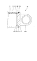
- FIG. 1 is a cross-sectional view of a fluid pressure cylinder provided with a cylinder tube according to a first embodiment of the present invention.
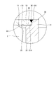
- FIG. 2 is an enlarged view of a portion A in FIG.
- FIG. 3 is sectional drawing explaining the manufacturing method of the cylinder tube which concerns on 1st Embodiment of this invention, and is a figure which shows the main-body part and cover part before joining.
- FIG. 4 is sectional drawing explaining the manufacturing method of the cylinder tube which concerns on 1st Embodiment of this invention, and is a figure which shows the state which inserted the insertion part of the cover part in the main-body part.
- FIG. 3 is sectional drawing explaining the manufacturing method of the cylinder tube which concerns on 1st Embodiment of this invention, and is a figure which shows the state which inserted the insertion part of the cover part in the main-body part.
- FIG. 5 is a cross-sectional view for explaining the method for manufacturing a cylinder tube according to the first embodiment of the present invention, and showing a state in which the main body portion and the lid portion are welded.
- FIG. 6 is a cross-sectional view for explaining the method for manufacturing a cylinder tube according to the first embodiment of the present invention, and showing a state before the molding step.
- FIG. 7 is a cross-sectional view for explaining the method for manufacturing a cylinder tube according to the first embodiment of the present invention, and showing the process of the forming step.
- FIG. 8 is a cross-sectional view for explaining the method for manufacturing a cylinder tube according to the second embodiment of the present invention, and showing a molding step.
- FIG. 9 is a cross-sectional view of a fluid pressure cylinder provided with a cylinder tube according to a second embodiment of the present invention.
- the pressure resistant device is a device in which pressure acts as an internal pressure from the fluid inside.
- the pressure resistant apparatus is the cylinder tube 100 used for the fluid pressure cylinder 1 which is operated by the fluid pressure of the working fluid in the two pressure chambers (the first fluid pressure chamber 4 and the second fluid pressure chamber 5) Will be explained.
- the fluid pressure cylinder 1 is inserted into the cylinder tube 100, the piston 2 sliding along the inner circumferential surface of the cylinder tube 100, and the cylinder tube 100 and connected to the piston 2. And a piston rod 3.
- the inside of the cylinder tube 100 is divided by the piston 2 into a first fluid pressure chamber 4 and a second fluid pressure chamber 5.
- the first fluid pressure chamber 4 and the second fluid pressure chamber 5 are filled with a working oil as a working fluid.
- mounting portions 20A, 3A for mounting the fluid pressure cylinder 1 to another device are respectively provided.
- the fluid pressure cylinder 1 is extended as hydraulic oil is supplied to the first fluid pressure chamber 4 and discharged from the second fluid pressure chamber 5 through a port (not shown) provided in the cylinder tube 100. Further, the hydraulic cylinder 1 is contracted by the hydraulic fluid being supplied to the second fluid pressure chamber 5 and being discharged from the first fluid pressure chamber 4. By supplying and discharging the hydraulic fluid to the first and second fluid pressure chambers 4 and 5 inside the cylinder tube 100 at the time of the expansion and contraction operation, the hydraulic pressure of the hydraulic fluid acts on the cylinder tube 100 as an internal pressure.
- the cylinder tube 100 has a cylindrical main body portion 10 having a through hole 11 as a hollow portion opened at both end faces, a lid portion 20 attached to one end of the main body portion 10 and closing one opening of the through hole 11 And.
- a cylinder head 6 for slidably supporting the piston rod 3 is attached.
- the cylinder head 6 is detachably provided to the main body 10 by a plurality of fastening bolts (not shown) aligned in the circumferential direction.
- the other opening of the through hole 11 is closed by the cylinder head 6.
- annular groove 11A having an arc-shaped cross section is formed over the entire circumference.
- the lid portion 20 is formed so as to protrude from the joint surface 21A of the base portion 21 having the joint surface 21A in contact with one end face 10A of the main body portion 10 and welded to the main body portion 10 and inserted into the through hole 11
- the insertion portion 22 and a protrusion 23 provided at the tip of the insertion portion 22 and in close contact with the inner peripheral surface of the through hole 11 over the entire circumference are provided.
- the outer diameter of the base 21 is formed to be the same as the outer diameter of the main body 10.
- the mounting portion 20A is provided on the side opposite to the insertion portion 22 in the base 21 (see FIG. 1).
- the insertion portion 22 has a proximal end (right end in FIG. 1) connected to the base 21 and is formed in a cylindrical shape extending in the axial direction of the main body 10 and protruding from the joint surface 21A of the base 21.
- the outer diameter of the insertion portion 22 is substantially the same as the inner diameter of the through hole 11, and the insertion portion 22 is fitted in the through hole 11. Thereby, centering (alignment) for welding the main body portion 10 and the lid portion 20 is performed.
- the projecting portion 23 is a caulking portion that is provided on the tip end portion (left end portion in FIG. 1) of the insertion portion 22 and is radially expanded outward by a tapered portion 2A formed on the piston 2.
- the projecting portion 23 is crimped radially outward over the entire circumference, and a part thereof is filled in the annular groove 11A of the through hole 11.
- the projecting portion 23 closely contacts the inner circumferential surface of the annular groove 11A in the through hole 11 over the entire circumference.
- the inner peripheral surface of the through hole 11 includes the inner peripheral surface of the annular groove 11A.
- the end face 10A of the main body portion 10 and the joint surface 21A of the base 21 of the lid portion 20 are welded to each other at the end faces, whereby the main body portion 10 and the lid portion 20 are integrated by the welding portion 30 to configure the cylinder tube 100 Do.
- the insertion portion of the lid is fitted in the through hole of the main body, and centering of both is performed.
- a slight gap hereinafter, referred to as “clearance 25” remains between the inner peripheral surface of the through hole and the outer peripheral surface of the insertion portion (see FIG. 2).
- the protrusion 23 is formed on the inner peripheral surface of the through hole 11 in the main body 10, more specifically, on the inner peripheral surface of the annular groove 11A formed on the inner peripheral surface of the through hole 11. In close contact. Thereby, the clearance 25 is closed and the communication between the clearance 25 and the first fluid pressure chamber 4 is blocked. For this reason, even during the expansion and contraction operation of the fluid pressure cylinder 1, the entry of the hydraulic pressure into the clearance 25 is prevented. Therefore, the stress concentration due to the internal pressure acting on the weld 30 is alleviated, and the durability of the cylinder tube 100 is improved.
- the outer circumferential surface of the projection 23 of the lid 20 is formed in a cylindrical surface shape that is uniform with the outer circumferential surface of the insertion portion 22. 22 has substantially the same outer diameter.
- the end face 10A of the main body 10 and the joint surface 21A of the base 21 are brought into contact with each other, and the insertion portion of the lid 20 is inserted into the through hole 11 of the main body 10. 22 is inserted and fitted (arrangement process). Thereby, the main body 10 and the lid 20 are coaxially arranged.
- the main body 10 and the base 21 of the lid 20 are welded and integrated (welding process).
- the welding part 30 which joins the end surface 10A of the main-body part 10 and the joint surface 21A of the base 21 of the cover part 20 is formed.
- Welding between the main body portion 10 and the lid portion 20 can be performed by any method such as arc welding including plasma welding and TIG welding, gas welding, laser welding, electron beam welding, resistance welding, friction welding, and diffusion bonding. .
- the piston 2 and the piston rod 3 are inserted into the main body 10 from the other opening of the through hole 11 in the main body 10, and the cylinder head 6 is inserted into the other opening of the through hole 11. Attach the (assembly process).
- a molding step of bringing the protrusion 23 into close contact with the inner peripheral surface of the through hole 11 is performed. Specifically, first, the first fluid pressure chamber 4 and the second fluid pressure chamber 5 in the cylinder tube 100 are filled with the hydraulic oil. Then, the hydraulic pressure is supplied to the second fluid pressure chamber 5, and the piston 2 and the piston rod 3 are moved in the direction in which the fluid pressure cylinder 1 contracts.
- the piston 2 has a tapered portion 2A which is inclined with respect to the central axis such that the outer diameter decreases toward the projecting portion 23.
- the tapered portion 2A is provided so as to abut on the projecting portion 23 when the piston 2 and the piston rod 3 move close to the stroke end in the contraction direction (right direction in FIG. 6).
- the fluid pressure cylinder 1 there is a process of operation confirmation in which the expansion and contraction operation is performed by oil pressure as the inspection after the assembly.
- the molding process for bringing the protrusion 23 into close contact with the inner circumferential surface of the through hole 11 is performed using the process of operation check after assembly. Specifically, the fluid pressure cylinder 1 is contracted at a predetermined pressure, and the piston 2 is moved to the stroke end in the contraction direction in which the piston 2 and the end face of the insertion portion 22 abut. Thereby, the operation confirmation of the contraction operation in the fluid pressure cylinder 1 and the step (forming step) of bringing the protrusion 23 into close contact with the inner peripheral surface of the through hole 11 are simultaneously performed. As described above, the manufacturing cycle can be shortened by simultaneously performing the operation check of the fluid pressure cylinder 1 and the step of bringing the protrusion 23 into close contact with the inner peripheral surface of the through hole 11.
- the projection 23 is in close contact with the inner peripheral surface of the through hole 11 using the piston 2 which is a component of the fluid pressure cylinder 1, a jig for expanding the diameter of the projection 23 is not necessary. Therefore, cost increase can also be prevented.
- the clearance 25 between the inner peripheral surface of the through hole 11 of the main body portion 10 and the outer peripheral surface of the insertion portion 22 of the lid 20 is a first fluid pressure by the projection 23 provided in the insertion portion 22.
- the communication with the chamber 4 is cut off. Accordingly, the hydraulic pressure is prevented from being led to the clearance 25, and the stress concentration in the welding portion 30 is alleviated. Therefore, the durability of the cylinder tube 100 can be improved.
- the annular groove 11A of the through hole 11 is partially filled with the projecting portion 23, and the projecting portion 23 is in close contact with the inner circumferential surface of the annular groove 11A over the entire circumference. Since the springback of the protrusion 23 is prevented by locking the enlarged protrusion 23 to the annular groove 11A, the communication between the clearance 25 and the first fluid pressure chamber 4 can be cut off more reliably. .
- the diameter of the projecting portion 23 is increased by the piston 2 moved by the hydraulic pressure so as to be in close contact with the inner circumferential surface of the annular groove 11A. Therefore, the molding process can be performed simultaneously with the operation confirmation of the fluid pressure cylinder 1, and the manufacturing cycle can be shortened. In addition, a jig for expanding the diameter of the protrusion 23 is also unnecessary. Therefore, the manufacturing cost of cylinder tube 100 can be reduced.
- the piston 2 is moved by hydraulic pressure, and the protrusion 23 is expanded in diameter by the piston 2 to be in close contact with the inner circumferential surface of the through hole 11.
- the second embodiment differs from the first embodiment in that the diameter of the projecting portion 23 is increased by the jig 102 so as not to use the piston 2 but to closely contact the inner peripheral surface of the through hole 11. Do.
- the steps up to the welding step are the same as those in the first embodiment, and thus the description thereof is omitted.
- the forming step is performed after the welding step. Specifically, as shown in FIG. 8, the jig 102 is inserted from the other opening of the through hole 11 in the main body 10, and the projection 23 is pressed by the jig 102. Similar to the piston 2 in the first embodiment, a tapered portion 102A is provided at the tip of the jig 102. By pressing the jig 102 toward the projecting portion 23, the projecting portion 23 is guided by the tapered portion 102A, and is plastically deformed outward in the radial direction over the entire circumference to be enlarged.
- the projecting portion 23 is filled in the annular groove 11A of the through hole 11, and the projecting portion 23 is in close contact with the inner circumferential surface of the annular groove 11A in the through hole 11.
- the forming process is performed using the jig 102, and then the assembling process is performed.
- the piston 2 since the piston 2 is not used to expand the diameter of the protrusion 23, as shown in FIG. 9, it is not necessary to provide the piston 2 with the tapered portion 2A in contact with the protrusion 23.
- the piston 2 is provided with a relief 2B for avoiding contact with the protrusion 23.
- the protrusion 23 separates from the piston 2 without contacting the piston 2. According to this, the stroke of the piston 2 in the contraction direction is not blocked by the projection 23. That is, the stroke end in the contraction direction can be reliably defined by the contact between the piston 2 and the insertion portion 22 of the lid 20.
- the cylinder tube 100 similar to the first embodiment can be manufactured.
- the annular groove 11A is provided on the inner peripheral surface of the through hole 11.
- the annular groove 11A may not necessarily be provided. Even in this case, the protrusion 23 is in close contact with the inner peripheral surface of the through hole 11 to prevent the hydraulic pressure from entering the clearance 25.
- the projecting portion 23 is filled in the annular groove 11A. That is, the protrusion 23 contacts substantially the entire axial direction of the annular groove 11A. On the other hand, the protrusion 23 may be in contact with only a part of the annular groove 11A in the axial direction.
- taper part 2A, 102A which contacts the protrusion part 23 is provided in piston 2 and the jig
- the piston 2 and the jig 102 can be formed in any shape as long as the protrusion 23 can be brought into close contact with the inner peripheral surface of the through hole 11.
- the inner peripheral surface of the protrusion 23 may be formed in a tapered shape.
- a curved surface portion in contact with the projecting portion 23 may be formed on the piston 2 or the jig 102.
- the cylinder tube 100 used for the fluid pressure cylinder 1 was demonstrated as a pressure
- the pressure resistant apparatus is not limited to this, and may be a pressure vessel such as a cylinder for storing liquid or gas.
- the pressure resistant device may be manufactured by the manufacturing method according to the second embodiment.
- the cylinder tube 100 includes a main body portion 10 having a through hole 11 opening at the end face 10 A, and a lid portion 20 closing the opening of the through hole 11 of the main body portion 10.
- the lid portion 20 is an end face of the main body portion 10 A base 21 having a joint surface 21A to be welded to 10A, an insertion portion 22 formed to project from the joint surface 21A and inserted into the through hole 11, and an inner circumferential surface of the through hole 11 provided in the insertion portion 22 And a protrusion 23 closely attached to the
- annular groove 11A is provided on the inner peripheral surface of the through hole 11, and the protrusion 23 is in close contact with the inner peripheral surface of the annular groove 11A over the entire circumference.
- the protruding portion 23 is a caulking portion pressed against the inner peripheral surface of the through hole 11 by plastic deformation.
- the fluid pressure cylinder 1 includes a cylinder tube 100 and a piston 2 that divides the inside of the cylinder tube 100 into a first fluid pressure chamber 4 and a second fluid pressure chamber 5, and the piston 2 can abut on the protrusion 23 Tapered portion 2A.
- the method of manufacturing the cylinder tube 100 including the main body portion 10 having the through hole 11 opened to the end face 10A and the lid portion 20 closing the opening of the through hole 11 of the main body portion 10 is the base 21 provided on the lid portion 20 Placing the joint surface 21A of the main body 10 in contact with the end face 10A of the main body 10 and inserting the insertion portion 22 projecting from the joint surface 21A into the through hole 11 of the main body 10; And a forming step of plastically deforming the protruding portion 23 provided in the insertion portion 22 and closely contacting the inner peripheral surface of the through hole 11 over the entire circumference.
- the annular groove 11A is provided on the inner peripheral surface of the through hole 11, and in the forming step, the annular groove 11A is in close contact with the inner peripheral surface of the annular groove 11A The protrusion 23 is formed.
- the projecting portion 23 is pressed by the jig 102 inserted into the through hole 11 in close contact with the inner circumferential surface of the through hole 11 in the forming step.
- the piston 2 inserted into the main body 10 is moved by hydraulic pressure, and the projection 23 is pressed by the piston 2 Close to the inner surface of 11.
Landscapes
- Engineering & Computer Science (AREA)
- General Engineering & Computer Science (AREA)
- Mechanical Engineering (AREA)
- Chemical & Material Sciences (AREA)
- Combustion & Propulsion (AREA)
- Physics & Mathematics (AREA)
- Fluid Mechanics (AREA)
- Actuator (AREA)
- Pistons, Piston Rings, And Cylinders (AREA)
Abstract
シリンダチューブ(100)は、端面に開口する貫通孔(11)を有する本体部(10)と、本体部(10)の貫通孔(11)の開口を閉塞する蓋部(20)と、を備え、蓋部(20)は、本体部(10)の端面に溶接される接合面(21A)を有する基部(21)と、接合面(21A)から突出して形成され貫通孔(11)に挿入される挿入部(22)と、挿入部(22)に設けられ全周にわたって貫通孔(11)の内周面に密着する突出部(23)と、を有する。
Description
本発明は、耐圧機器、流体圧シリンダ、及び耐圧機器の製造方法に関する。
JP2002-257238Aには、シリンダチューブ部材とシリンダチューブ部材に嵌合差し込みされたヘッド部材とが溶接により接合され一体化された耐圧機器としてのシリンダチューブが開示されている。
JP2002-257238Aに開示されるようなシリンダチューブでは、シリンダチューブ部材の内周面とシリンダチューブ部材に嵌合するヘッド部材の外周面との間には、わずかなクリアランスが残存してしまう。このような耐圧機器では、このクリアランスを通じて内圧が導かれることで、溶接部分に応力集中が生じるおそれがある。
本発明は、耐圧機器の耐久性を向上させること目的とする。
本発明のある態様によれば、耐圧機器であって、端面に開口する中空部を有する本体部と、本体部の中空部の開口を閉塞する蓋部と、を備え、蓋部は、本体部の端面に溶接される接合面を有する基部と、接合面から突出して形成され中空部に挿入される挿入部と、挿入部に設けられ全周にわたって中空部の内周面に密着する突出部と、を有する。
本発明のある態様によれば、端面に開口する中空部を有する本体部と、本体部の中空部の開口を閉塞する蓋部と、を備える耐圧機器を製造する製造方法であって、蓋部における基部の接合面を本体部の端面に接触させると共に、接合面から突出する挿入部を本体部の中空部に挿入する配置工程と、基部の接合面と本体部の端面とを溶接する溶接工程と、挿入部に設けられる突出部を塑性変形させ、全周にわたって中空部の内周面に密着させる成形工程と、を備える。
以下、添付図面を参照しながら本発明の実施形態に係る耐圧機器について説明する。
(第1実施形態)
耐圧機器は、内部の流体から内圧として圧力が作用する機器である。以下では、耐圧機器が、二つの圧力室(第1流体圧室4、第2流体圧室5)内の作動流体の流体圧により伸縮作動する流体圧シリンダ1に用いられるシリンダチューブ100である場合について説明する。
耐圧機器は、内部の流体から内圧として圧力が作用する機器である。以下では、耐圧機器が、二つの圧力室(第1流体圧室4、第2流体圧室5)内の作動流体の流体圧により伸縮作動する流体圧シリンダ1に用いられるシリンダチューブ100である場合について説明する。
図1に示すように、流体圧シリンダ1は、円筒状のシリンダチューブ100と、シリンダチューブ100の内周面に沿って摺動するピストン2と、シリンダチューブ100内に挿入されピストン2に連結されるピストンロッド3と、を備える。
シリンダチューブ100の内部は、ピストン2によって、第1流体圧室4及び第2流体圧室5に仕切られる。第1流体圧室4及び第2流体圧室5には、作動流体としての作動油が充填される。
シリンダチューブ100の端部とピストンロッド3の先端部とには、流体圧シリンダ1を他の機器に取り付けるための取付部20A,3Aがそれぞれ設けられる。
流体圧シリンダ1は、シリンダチューブ100に設けられるポート(図示省略)を通じて作動油が第1流体圧室4に供給されるとともに第2流体圧室5から排出されることで伸長作動する。また、流体圧シリンダ1は、作動油が第2流体圧室5に供給されるとともに第1流体圧室4から排出されることで収縮作動する。伸縮作動時にシリンダチューブ100の内部の第1,第2流体圧室4,5に作動油が給排されることにより、シリンダチューブ100には作動油の油圧が内圧として作用する。
シリンダチューブ100は、両端面に開口する中空部としての貫通孔11を有する筒状の本体部10と、本体部10の一端部に取り付けられ貫通孔11の一方の開口を閉塞する蓋部20と、を備える。
本体部10の他端部には、ピストンロッド3を摺動自在に支持するシリンダヘッド6が取り付けられる。シリンダヘッド6は、周方向に並ぶ複数の締結ボルト(図示省略)によって本体部10に着脱可能に設けられる。貫通孔11の他方の開口は、シリンダヘッド6により閉塞される。
図2に示すように、本体部10における貫通孔11の一端部の内周面には、断面円弧状の環状溝11Aが全周にわたって形成される。
蓋部20は、本体部10の一方の端面10Aに当接し本体部10に溶接される接合面21Aを有する基部21と、基部21の接合面21Aから突出して形成され貫通孔11に挿入される挿入部22と、挿入部22の先端部に設けられ全周にわたって貫通孔11の内周面に密着する突出部23と、を有する。
基部21の外径は、本体部10の外径と同一となるように形成される。基部21において、挿入部22とは反対側に取付部20Aが設けられる(図1参照)。
挿入部22は、その基端部(図1中右側端部)が基部21に接続され、本体部10の軸方向に延びて基部21の接合面21Aから突出する円柱状に形成される。挿入部22は、外径が貫通孔11の内径とほぼ同一に形成され、貫通孔11に嵌合する。これにより、本体部10と蓋部20とを溶接するための芯出し(調心)が行われる。
突出部23は、挿入部22の先端部(図1中左側端部)に設けられ、ピストン2に形成されるテーパ部2Aによって径方向外側に拡径されて形成されるかしめ部である。突出部23は、全周にわたって径方向外側にかしめられ、その一部が貫通孔11の環状溝11Aに充填される。このようにして、突出部23は、全周にわたって貫通孔11における環状溝11Aの内周面に密着する。なお、貫通孔11の内周面とは、環状溝11Aの内周面を含むものである。
本体部10の端面10Aと蓋部20における基部21の接合面21Aとが互いに端面同士で溶接されることにより、本体部10と蓋部20とが溶接部30によって一体化してシリンダチューブ100を構成する。
ここで、本体部と蓋部とを精度良く溶接するには、両者の芯ずれを抑制する必要がある。このため、本体部の貫通孔に蓋部の挿入部を嵌合させ、両者の芯出しが行われる。しかしながら、一般には、貫通孔の内周面と挿入部の外周面との間には、わずかな隙間(以下、「クリアランス25」と称する。)が残存してしまう(図2参照)。
このため、流体圧シリンダの伸縮作動時には、このクリアランス25に作動油圧が浸入し、内圧が作用する。このような内圧によれば、本体部には、外側へ向けて膨らむような力が作用する。このような力により、本体部と蓋部との接合部分である溶接部には、応力集中が生じる。
これに対し、本実施形態では、突出部23が本体部10における貫通孔11の内周面、より具体的には、貫通孔11の内周面に形成された環状溝11Aの内周面に密着する。これにより、クリアランス25が塞がれて、クリアランス25と第1流体圧室4との連通が遮断される。このため、流体圧シリンダ1の伸縮作動中においても、クリアランス25への作動油圧の侵入が防止される。したがって、内圧が溶接部30に作用することによる応力集中が緩和され、シリンダチューブ100の耐久性が向上する。
次に、図3及び図4を参照して、シリンダチューブ100の製造方法について具体的に説明する。
図3に示すように、本体部10と蓋部20の結合前では、蓋部20の突出部23は、外周面が挿入部22の外周面と一様な円筒面状に形成され、挿入部22と略同一外径を有する。
シリンダチューブ100の製造では、まず、図4に示すように、本体部10の端面10Aと基部21の接合面21Aを対向させて接触させ、本体部10の貫通孔11に蓋部20の挿入部22を挿入して嵌合させる(配置工程)。これにより、本体部10と蓋部20とが同軸的に配置される。
次に、蓋部20の挿入部22を本体部10の貫通孔11に嵌合させた状態で、本体部10と蓋部20の基部21とを溶接して一体化させる(溶接工程)。これにより、図5に示すように、本体部10の端面10Aと蓋部20の基部21の接合面21Aとを接合する溶接部30が形成される。本体部10と蓋部20との溶接は、プラズマ溶接やTIG溶接を含むアーク溶接、ガス溶接、レーザー溶接、電子ビーム溶接、抵抗溶接、摩擦圧接、及び拡散接合など任意の方法により行うことができる。
次に、図6に示すように、本体部10における貫通孔11の他方の開口から、ピストン2及びピストンロッド3を本体部10内に挿入すると共に、貫通孔11の他方の開口にシリンダヘッド6を取り付ける(組み立て工程)。
次に、突出部23を貫通孔11の内周面に密着させる成形工程が行われる。具体的には、まず、シリンダチューブ100内の第1流体圧室4及び第2流体圧室5に作動油を充填する。そして、第2流体圧室5に油圧を供給し、流体圧シリンダ1が収縮作動する方向へ、ピストン2及びピストンロッド3を移動させる。
ここで、ピストン2は、図6等に示すように、突出部23に向かうにつれ外径が減少するように中心軸に対して傾斜するテーパ部2Aを有する。テーパ部2Aは、ピストン2及びピストンロッド3が収縮方向(図6中右方向)のストローク端付近にまで移動すると、突出部23に当接するように設けられる。
ピストン2が挿入部22の端面に当接する収縮方向のストローク端付近までピストン2が移動すると、ピストン2のテーパ部2Aと突出部23とが接触する(図7参照)。この状態から、収縮方向のストローク端となるまでピストン2をさらに移動させると、突出部23は、テーパ部2Aによって案内されて、全周にわたり径方向外側へ塑性変形して拡径される。これにより、図2に示すように、貫通孔11の環状溝11Aには、突出部23が充填される。このようにして、油圧により移動するピストン2によって突出部23を押圧することで、突出部23を貫通孔11における環状溝11Aの内周面に密着させる。
流体圧シリンダ1では、組み立て後の検査として、油圧によって伸縮作動させる動作確認の工程がある。突出部23を貫通孔11の内周面に密着させる成形工程は、組み立て後の動作確認の工程を利用して行われる。具体的には、所定の圧力で流体圧シリンダ1を収縮作動させて、ピストン2と挿入部22の端面とが当接する収縮方向のストローク端となるまでピストン2を移動させる。これにより、流体圧シリンダ1における収縮作動の動作確認と、突出部23を貫通孔11の内周面に密着させる工程(成形工程)と、が同時に行われる。このように、流体圧シリンダ1の動作確認と貫通孔11の内周面へ突出部23を密着させる工程とを同時に行うことで、製造サイクルを短縮することができる。
また、流体圧シリンダ1の構成部品であるピストン2を用いて突出部23を貫通孔11の内周面に密着させるため、突出部23を拡径するための治具などが不要となる。よって、コスト増加を防止することもできる。
以上の第1実施形態によれば、以下に示す効果を奏する。
シリンダチューブ100では、本体部10の貫通孔11の内周面と蓋部20の挿入部22の外周面との間のクリアランス25は、挿入部22に設けられる突出部23によって、第1流体圧室4との連通が遮断される。よって、油圧がクリアランス25に導かれることが防止され、溶接部30における応力集中が緩和される。したがって、シリンダチューブ100の耐久性を向上させることができる。
また、シリンダチューブ100では、貫通孔11の環状溝11Aに突出部23の一部が充填され、突出部23は全周にわたって環状溝11Aの内周面に密着する。拡径された突出部23が環状溝11Aに係止することで突出部23のスプリングバックが防止されるため、クリアランス25と第1流体圧室4との連通をより確実に遮断することができる。
また、第1実施形態に係るシリンダチューブ100の製造方法では、油圧によって移動するピストン2により突出部23を拡径して環状溝11Aの内周面に密着させる。よって、流体圧シリンダ1の動作確認と同時に成形工程を行うことができ、製造サイクルを短縮することができる。また、突出部23を拡径するための治具も不要となる。したがって、シリンダチューブ100の製造コストを低減することができる。
(第2実施形態)
次に、図8及び図9を参照して、本発明の第2実施形態について説明する。なお、以下では、上記第1実施形態と異なる点を中心に説明し、上記第1実施形態と同一の構成には同一の符号を付して説明を省略する。
次に、図8及び図9を参照して、本発明の第2実施形態について説明する。なお、以下では、上記第1実施形態と異なる点を中心に説明し、上記第1実施形態と同一の構成には同一の符号を付して説明を省略する。
上記第1実施形態では、油圧によってピストン2を移動させ、ピストン2によって突出部23を拡径して貫通孔11の内周面に密着させる。
これに対し、第2実施形態では、ピストン2を利用せず、治具102によって突出部23を拡径して貫通孔11の内周面に密着させる点で、上記第1実施形態とは相違する。
第2実施形態に係る製造方法では、溶接工程までの工程は、上記第1実施形態と同様であるため、説明を省略する。
第2実施形態に係る製造方法では、溶接工程の後に、成形工程が行われる。具体的には、図8に示すように、本体部10における貫通孔11の他方の開口から治具102を内部に挿入し、治具102によって突出部23を押圧する。第1実施形態におけるピストン2と同様に、治具102の先端には、テーパ部102Aが設けられる。治具102を突出部23に向けて押圧することで、突出部23は、テーパ部102Aによって案内されて、全周にわたり径方向外側へ塑性変形して拡径される。これにより、貫通孔11の環状溝11Aには突出部23が充填され、突出部23が貫通孔11における環状溝11Aの内周面に密着する。このようにして、シリンダチューブ100の製造が完了する。
次に、本体部10における貫通孔11の他方の開口から、ピストン2及びピストンロッド3を本体部10内に挿入すると共に、貫通孔11の他方の開口にシリンダヘッド6を取り付ける。これにより、流体圧シリンダ1の組み立て(製造)が完了する。
このように、第2実施形態では、溶接工程の後に、治具102を用いて成形工程が行われ、その後組み立て工程が行われる。
なお、第2実施形態では、突出部23の拡径にピストン2を利用しないため、図9に示すように、突出部23と接触するテーパ部2Aをピストン2に設けなくてよい。第2実施形態では、ピストン2には突出部23との接触を避けるための逃げ部2Bが設けられる。これにより、ピストン2が収縮方向のストローク端まで移動した際、突出部23はピストン2には接触せずに離間する。これによれば、収縮方向へのピストン2のストロークが突出部23によって阻害されない。つまり、ピストン2と蓋部20の挿入部22との接触によって確実に収縮方向のストローク端を規定することができる。
以上の第2実施形態によっても、上記第1実施形態と同様のシリンダチューブ100を製造することができる。
次に、上記各実施形態の変形例について説明する。以下のような変形例も本発明の範囲内であり、以下の変形例と上記実施形態の各構成とを組み合わせたり、上記の異なる実施形態で説明した構成同士を組み合わせたり、以下の変形例同士を組み合わせたりすることも可能である。
上記各実施形態では、貫通孔11の内周面に環状溝11Aが設けられる。これに対し、環状溝11Aは必ずしも設けなくてよい。この場合であっても、突出部23が貫通孔11の内周面に密着することで、クリアランス25への油圧の侵入は防止される。
また、上記各実施形態では、環状溝11Aには、突出部23が充填される。つまり、突出部23は、環状溝11Aの軸方向のほぼ全体に対して接触する。これに対し、突出部23は、環状溝11Aにおける軸方向の一部にのみ接触するものでもよい。
また、上記各実施形態では、ピストン2や治具102に突出部23と接触するテーパ部2A,102Aが設けられる。これに対し、突出部23を貫通孔11の内周面に密着させることができる限り、ピストン2や治具102は任意の形状に形成することができる。例えば、ピストン2や治具102にテーパ部2A,102Aを設けず、突出部23の内周面をテーパ状に形成してもよい。また、テーパ部2A,102Aに代えて、例えば、突出部23に接触する曲面部をピストン2や治具102に形成してもよい。
また、上記実施形態では、耐圧機器として、流体圧シリンダ1に用いられるシリンダチューブ100について説明した。耐圧機器は、これに限らず、液体や気体を保管するためのボンベなどの圧力容器でもよい。流体圧によって移動するピストン2が内部に設けられない耐圧機器の場合には、上記第2実施形態に係る製造方法により耐圧機器を製造すればよい。
以下、本発明の実施形態の構成、作用、及び効果をまとめて説明する。
シリンダチューブ100は、端面10Aに開口する貫通孔11を有する本体部10と、本体部10の貫通孔11の開口を閉塞する蓋部20と、を備え、蓋部20は、本体部10の端面10Aに溶接される接合面21Aを有する基部21と、接合面21Aから突出して形成され貫通孔11に挿入される挿入部22と、挿入部22に設けられ全周にわたって貫通孔11の内周面に密着する突出部23と、を有する。
この構成では、突出部23が全周にわたって貫通孔11の内周面に密着するため、貫通孔11の内周面と挿入部22の外周面との間のクリアランス25を通じて溶接部30に内圧が作用することが防止される。したがって、シリンダチューブ100の耐久性が向上する。
また、シリンダチューブ100では、貫通孔11の内周面には、環状溝11Aが設けられ、突出部23は、全周にわたって環状溝11Aの内周面に密着する。
この構成では、突出部23が環状溝11Aに係止されるため、両者の離間が防止され、貫通孔11と挿入部22との間のクリアランス25をより確実に塞ぐことができる。
また、シリンダチューブ100では、突出部23は、塑性変形によって貫通孔11の内周面に押し付けられるかしめ部である。
流体圧シリンダ1は、シリンダチューブ100と、シリンダチューブ100の内部を第1流体圧室4及び第2流体圧室5に仕切るピストン2と、を備え、ピストン2は、突出部23に当接可能なテーパ部2Aを有する。
この構成では、流体圧シリンダ1の構成部品であるピストン2によって、突出部23を貫通孔11の内周面に押圧することができるため、治具等が不要となり、製造コストが低減される。
端面10Aに開口する貫通孔11を有する本体部10と、本体部10の貫通孔11の開口を閉塞する蓋部20と、を備えるシリンダチューブ100の製造方法は、蓋部20に設けられる基部21の接合面21Aを本体部10の端面10Aに接触させると共に、接合面21Aから突出する挿入部22を本体部10の貫通孔11に挿入する配置工程と、基部21の接合面21Aと本体部10の端面10Aとを溶接する溶接工程と、挿入部22に設けられる突出部23を塑性変形させ、全周にわたって貫通孔11の内周面に密着させる成形工程と、を備える。
この構成では、全周にわたって貫通孔11の内周面に密着する突出部23が形成されるため、貫通孔11の内周面と挿入部22の外周面との間のクリアランス25を通じて溶接部30に内圧が作用することが防止される。したがって、シリンダチューブ100の耐久性が向上する。
また、上記各実施形態に係るシリンダチューブ100の製造方法では、貫通孔11の内周面には、環状溝11Aが設けられ、成形工程では、全周にわたって環状溝11Aの内周面に密着する突出部23を形成する。
この構成では、突出部23が環状溝11Aに係止されるため、両者の離間が防止され、貫通孔11と挿入部22との間のクリアランス25をより確実に塞ぐことができる。
また、上記第2実施形態に係るシリンダチューブ100の製造方法は、成形工程では、貫通孔11に挿入される治具102によって突出部23を押圧して貫通孔11の内周面に密着させる。
また、上記第1実施形態に係るシリンダチューブ100の製造方法は、成形工程では、本体部10内に挿入されるピストン2を油圧によって移動させて、ピストン2によって突出部23を押圧して貫通孔11の内周面に密着させる。
この構成では、流体圧シリンダ1の動作確認と共に成形工程を行うことができるため、製造サイクルを低減することができる。
以上、本発明の実施形態について説明したが、上記各実施形態は本発明の適用例の一つを示したに過ぎず、本発明の技術的範囲を上記実施形態の具体的構成に限定する趣旨ではない。
本願は2017年11月10日に日本国特許庁に出願された特願2017-217515に基づく優先権を主張し、この出願の全ての内容は参照により本明細書に組み込まれる。
Claims (8)
- 耐圧機器であって、
端面に開口する中空部を有する本体部と、
前記本体部の前記中空部の開口を閉塞する蓋部と、を備え、
前記蓋部は、
前記本体部の前記端面に溶接される接合面を有する基部と、
前記接合面から突出して形成され前記中空部に挿入される挿入部と、
前記挿入部に設けられ全周にわたって前記中空部の内周面に密着する突出部と、を有する、
耐圧機器。 - 請求項1に記載の耐圧機器であって、
前記中空部の内周面には、環状溝が設けられ、
前記突出部は、全周にわたって前記環状溝の内周面に密着する、
耐圧機器。 - 請求項1に記載の耐圧機器であって、
前記突出部は、塑性変形によって前記中空部の前記内周面に押し付けられるかしめ部である、
耐圧機器。 - 流体圧シリンダであって、
請求項1に記載の耐圧機器としてのシリンダチューブと、
前記シリンダチューブの内部を第1流体圧室及び第2流体圧室に仕切るピストンと、を備え、
前記ピストンは、前記突出部に当接可能なテーパ部を有する、
流体圧シリンダ。 - 端面に開口する中空部を有する本体部と、前記本体部の前記中空部の開口を閉塞する蓋部と、を備える耐圧機器を製造する製造方法であって、
前記蓋部における基部の接合面を前記本体部の前記端面に接触させると共に、前記接合面から突出する挿入部を前記本体部の前記中空部に挿入する配置工程と、
前記基部の前記接合面と前記本体部の前記端面とを溶接する溶接工程と、
前記挿入部に設けられる突出部を塑性変形させ、全周にわたって前記中空部の内周面に密着させる成形工程と、を備える、
耐圧機器の製造方法。 - 請求項5に記載の耐圧機器の製造方法であって、
前記中空部の内周面には、環状溝が設けられ、
前記成形工程では、全周にわたって前記環状溝の内周面に前記突出部を密着させる、
耐圧機器の製造方法。 - 請求項5に記載の耐圧機器の製造方法であって、
前記成形工程では、前記中空部に挿入される治具によって前記突出部を押圧して前記中空部の前記内周面に密着させる、
耐圧機器の製造方法。 - 請求項5に記載の耐圧機器の製造方法であって、
前記耐圧機器は、流体圧シリンダに用いられるシリンダチューブであって、
前記成形工程では、前記本体部内に挿入されるピストンを流体圧によって移動させて、前記ピストンによって前記突出部を押圧して前記中空部の内周面に密着させる、
耐圧機器の製造方法。
Applications Claiming Priority (2)
| Application Number | Priority Date | Filing Date | Title |
|---|---|---|---|
| JP2017217515A JP6924122B2 (ja) | 2017-11-10 | 2017-11-10 | 耐圧機器、流体圧シリンダ、及び耐圧機器の製造方法 |
| JP2017-217515 | 2017-11-10 |
Publications (1)
| Publication Number | Publication Date |
|---|---|
| WO2019093274A1 true WO2019093274A1 (ja) | 2019-05-16 |
Family
ID=66438849
Family Applications (1)
| Application Number | Title | Priority Date | Filing Date |
|---|---|---|---|
| PCT/JP2018/041015 Ceased WO2019093274A1 (ja) | 2017-11-10 | 2018-11-05 | 耐圧機器、流体圧シリンダ、及び耐圧機器の製造方法 |
Country Status (2)
| Country | Link |
|---|---|
| JP (1) | JP6924122B2 (ja) |
| WO (1) | WO2019093274A1 (ja) |
Cited By (1)
| Publication number | Priority date | Publication date | Assignee | Title |
|---|---|---|---|---|
| JP2024512877A (ja) * | 2021-03-02 | 2024-03-21 | ビューラハ エンジニアリング インターナショナル ベー.フェー. | 作動シリンダ及びその製造方法 |
Citations (4)
| Publication number | Priority date | Publication date | Assignee | Title |
|---|---|---|---|---|
| JPS58149606U (ja) * | 1982-03-31 | 1983-10-07 | ティー・シー・エム株式会社 | 流体圧シリンダ |
| JPS60196003U (ja) * | 1984-06-01 | 1985-12-27 | 株式会社ナブコ | 油圧シリンダ |
| JPS61124704U (ja) * | 1985-01-25 | 1986-08-06 | ||
| JPS62140206U (ja) * | 1986-02-28 | 1987-09-04 |
Family Cites Families (5)
| Publication number | Priority date | Publication date | Assignee | Title |
|---|---|---|---|---|
| US5465647A (en) * | 1994-11-14 | 1995-11-14 | Polygon Company | Fluid cylinder end cap assembly |
| US5651303A (en) * | 1994-11-14 | 1997-07-29 | Polygon Company | Fluid cylinder end cap assembly |
| JP2001227465A (ja) * | 2000-02-18 | 2001-08-24 | Toyota Autom Loom Works Ltd | 圧縮機用中空ピストンの製造方法 |
| US7100492B2 (en) * | 2004-10-06 | 2006-09-05 | Polygon Company | End cap assembly |
| JP6611544B2 (ja) * | 2015-10-05 | 2019-11-27 | Kyb−Ys株式会社 | 接合体、流体圧シリンダ、及び接合体の製造方法 |
-
2017
- 2017-11-10 JP JP2017217515A patent/JP6924122B2/ja active Active
-
2018
- 2018-11-05 WO PCT/JP2018/041015 patent/WO2019093274A1/ja not_active Ceased
Patent Citations (4)
| Publication number | Priority date | Publication date | Assignee | Title |
|---|---|---|---|---|
| JPS58149606U (ja) * | 1982-03-31 | 1983-10-07 | ティー・シー・エム株式会社 | 流体圧シリンダ |
| JPS60196003U (ja) * | 1984-06-01 | 1985-12-27 | 株式会社ナブコ | 油圧シリンダ |
| JPS61124704U (ja) * | 1985-01-25 | 1986-08-06 | ||
| JPS62140206U (ja) * | 1986-02-28 | 1987-09-04 |
Cited By (2)
| Publication number | Priority date | Publication date | Assignee | Title |
|---|---|---|---|---|
| JP2024512877A (ja) * | 2021-03-02 | 2024-03-21 | ビューラハ エンジニアリング インターナショナル ベー.フェー. | 作動シリンダ及びその製造方法 |
| JP7778152B2 (ja) | 2021-03-02 | 2025-12-01 | ビューマッハ エンジニアリング インターナショナル ベー.フェー. | 作動シリンダ及びその製造方法 |
Also Published As
| Publication number | Publication date |
|---|---|
| JP2019090433A (ja) | 2019-06-13 |
| JP6924122B2 (ja) | 2021-08-25 |
Similar Documents
| Publication | Publication Date | Title |
|---|---|---|
| KR100261958B1 (ko) | 아이조인트와 세경금속관의 연결구조 및 연결방법 | |
| US20100140920A1 (en) | Pipe joint including a pipe and method for producing a joint section of a pipe joint | |
| US11534852B2 (en) | Manufacturing method of joined body and joined body | |
| US20080314113A1 (en) | Processing method of tube body, manufacturing method of cylinder device and cylinder device manufactured by the same | |
| WO2019039503A1 (ja) | 成形方法及び成形装置 | |
| JP6611544B2 (ja) | 接合体、流体圧シリンダ、及び接合体の製造方法 | |
| JP6342018B2 (ja) | 特に燃料圧送システムのためのユニット及びその製造方法 | |
| KR101872982B1 (ko) | 실린더 장치 | |
| WO2012161159A1 (ja) | 流体圧シリンダに用いられるピストンの連結構造及びその連結方法 | |
| JP5046085B2 (ja) | 接合ロッドおよびシリンダ装置の製造方法 | |
| WO2019093274A1 (ja) | 耐圧機器、流体圧シリンダ、及び耐圧機器の製造方法 | |
| US11098800B2 (en) | Joined connection on a two-part piston and joining method | |
| JP2009202193A (ja) | 2部材の結合方法 | |
| US11441688B2 (en) | Component of hydraulics, arrangement having a portion of the component, and method for joining together the component | |
| JP4852599B2 (ja) | 圧力流体用フランジ連結 | |
| JP2012092897A (ja) | 管体の接続構造及びホース継手金具 | |
| JP2019063853A (ja) | 耐圧機器及び流体圧シリンダ | |
| CN119078206A (zh) | 一种高压减振软管扣压工装 | |
| JP2006095593A (ja) | 筒体の製造方法 | |
| JP7564008B2 (ja) | 軸合わせ用治具 | |
| JP4317524B2 (ja) | カムシャフト | |
| JP2019027464A (ja) | 継手及び継手の製造方法 | |
| WO2007070003A1 (en) | A method for manufacturing of a tubular element comprising a tube with a fixedly arranged flange | |
| CN119998561A (zh) | 阻尼缸结构单元 | |
| JP2016068127A (ja) | 接合方法及び接合体 |
Legal Events
| Date | Code | Title | Description |
|---|---|---|---|
| 121 | Ep: the epo has been informed by wipo that ep was designated in this application |
Ref document number: 18875634 Country of ref document: EP Kind code of ref document: A1 |
|
| NENP | Non-entry into the national phase |
Ref country code: DE |
|
| 122 | Ep: pct application non-entry in european phase |
Ref document number: 18875634 Country of ref document: EP Kind code of ref document: A1 |