WO2019092978A1 - サーモサイフォン式の温度調整装置 - Google Patents
サーモサイフォン式の温度調整装置 Download PDFInfo
- Publication number
- WO2019092978A1 WO2019092978A1 PCT/JP2018/033550 JP2018033550W WO2019092978A1 WO 2019092978 A1 WO2019092978 A1 WO 2019092978A1 JP 2018033550 W JP2018033550 W JP 2018033550W WO 2019092978 A1 WO2019092978 A1 WO 2019092978A1
- Authority
- WO
- WIPO (PCT)
- Prior art keywords
- temperature
- amount
- liquid phase
- refrigerant
- physical quantity
- Prior art date
Links
Images


Classifications
-
- F—MECHANICAL ENGINEERING; LIGHTING; HEATING; WEAPONS; BLASTING
- F28—HEAT EXCHANGE IN GENERAL
- F28D—HEAT-EXCHANGE APPARATUS, NOT PROVIDED FOR IN ANOTHER SUBCLASS, IN WHICH THE HEAT-EXCHANGE MEDIA DO NOT COME INTO DIRECT CONTACT
- F28D15/00—Heat-exchange apparatus with the intermediate heat-transfer medium in closed tubes passing into or through the conduit walls ; Heat-exchange apparatus employing intermediate heat-transfer medium or bodies
- F28D15/02—Heat-exchange apparatus with the intermediate heat-transfer medium in closed tubes passing into or through the conduit walls ; Heat-exchange apparatus employing intermediate heat-transfer medium or bodies in which the medium condenses and evaporates, e.g. heat pipes
- F28D15/06—Control arrangements therefor
Definitions
- the present disclosure relates to a thermosiphon temperature control device.
- thermosyphon temperature control device In order to adjust the temperature of a target device, a loop-type thermosyphon temperature control device is used. Such a temperature control device is described, for example, in Patent Document 1.
- the battery temperature control device described in Patent Document 1 evaporates the refrigerant that is the working fluid by heat absorption from the battery in the inside of the evaporator that is the battery temperature control unit, and also uses the heat medium cooling unit for the evaporated refrigerant. By condensing with a certain condenser, it is comprised so that the battery which is an object apparatus may be cooled.
- a temperature control apparatus like patent document 1, it is comprised so that the liquid phase refrigerant
- the inner wall surface of the heat exchanger is wetted by bubbles or the like due to the boiling of the liquid phase refrigerant, in the upper part of the liquid surface of the liquid phase refrigerant. That is, if the amount of working fluid enclosed inside the temperature control device is an appropriate amount, the inner wall surface of the heat exchanger can be evenly wetted, so the entire target device can be cooled by the latent heat of evaporation.
- the amount of the working fluid in the temperature control device is not an appropriate amount, a portion not wet by bubbles or the like due to boiling of the liquid-phase refrigerant may occur on the inner wall surface of the heat exchanger.
- the evaporation of the liquid-phase refrigerant does not occur on the surface of the inner wall surface of the heat exchanger which is not wetted by the liquid-phase refrigerant, so the target device can not be cooled and so-called dryout occurs. .
- Patent Document 1 does not have a configuration for detecting the amount of working fluid enclosed in the temperature control device. For this reason, in patent document 1, it was difficult to manage the quantity of the working fluid inside a temperature control apparatus.
- An object of the present disclosure is to provide a thermosiphon-type temperature control device capable of estimating the fluid sealing amount of a working fluid sealed inside.
- thermosiphon-type temperature control device the working fluid enclosed in the fluid circulation circuit is circulated by evaporating and condensing in the heat exchanger and condenser for the equipment, and the heat exchanger for the equipment is circulated.
- heat can be transferred to the target device.
- the physical quantity correlated with the temperature of the working fluid is closely related to the state of the working fluid in the gas phase and the working fluid in the liquid phase in the fluid circulation circuit.
- thermosiphon-type temperature control device the state of the gas phase / liquid phase of the working fluid enclosed in the fluid circulation circuit can be estimated using the physical quantity detected by the physical quantity detection unit. It is possible to estimate the amount of fluid enclosed in the fluid circulation circuit with a certain accuracy.
- thermosiphon temperature control device can provide the user with an index for evaluating the amount of fluid enclosed in the fluid circulation circuit, and can contribute to maintaining the temperature control performance of the target device properly.
- thermosiphon-type temperature control device 1 is applied as a device that adjusts the temperature of the battery pack BP mounted on a vehicle.
- working which does not show in figure the assembled battery BP as a power supply can be mentioned, for example.
- the temperature control device 1 can be applied to the battery pack BP of an electric vehicle or a hybrid vehicle.
- the battery pack BP is formed of a stacked body in which a plurality of rectangular battery cells BC are stacked, and is a target device for temperature control. In the battery pack BP, the plurality of battery cells BC are electrically connected in series. Each battery cell BC is configured of a chargeable / dischargeable secondary battery (for example, a lithium ion battery, a lead storage battery).
- a chargeable / dischargeable secondary battery for example, a lithium ion battery, a lead storage battery.
- the outer shape of the battery cell BC is not limited to the rectangular parallelepiped shape, and may be another shape such as a cylindrical shape.
- the battery pack BP may be configured to include battery cells BC electrically connected in parallel.
- the battery assembly BP configured in this manner generates heat when power supply or the like is performed during traveling of a vehicle or the like. Deterioration of the battery cell BC is promoted when the assembled battery BP becomes excessively hot due to self-heating.
- the battery pack BP if the temperature of each battery cell BC is uneven, the degree of progress of the deterioration of each battery cell BC is biased. Since the battery pack BP includes a series connection of the battery cells BC, the input / output characteristics of the entire battery pack BP are determined according to the battery characteristics of the battery cell BC most deteriorated among the battery cells BC. It is determined.
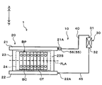
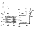
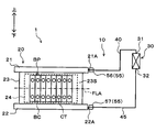
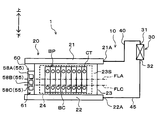
- the temperature control device 1 is applied to realize temperature control and temperature equalization of a battery pack BP as a target device, and a fluid circulation circuit 10 in which a refrigerant as a working fluid circulates, And a device control device 50.
- Arrows in FIG. 1 and the like indicate the upper side and the lower side in the gravity direction.
- the fluid circulation circuit 10 is a heat pipe that transfers heat by evaporation and condensation of the refrigerant as the working fluid, and a flow path through which a gas phase refrigerant flows and a liquid phase refrigerant It is configured as a loop-type thermosiphon separated from the flow channel.
- a fluorocarbon-based refrigerant for example, R134a, R1234yf, etc.
- the working fluid it is possible to use not only fluorocarbon-based refrigerants but also other refrigerants such as carbon dioxide, antifreeze liquid, and the like.
- the fluid circulation circuit 10 includes a device heat exchanger 20, a condenser 30, a gas phase side pipe 40, and a liquid phase side pipe 45.
- the fluid circulation circuit 10 constitutes a closed annular fluid circuit by connecting the device heat exchanger 20, the condenser 30, the gas phase side piping 40, and the liquid phase side piping 45 to one another.
- a refrigerant as a working fluid is enclosed in a state where the inside is evacuated.
- the device heat exchanger 20 is a heat exchanger that performs heat exchange between the refrigerant in the device heat exchanger 20 and the assembled battery BP when performing temperature adjustment of the assembled battery BP that is the target device.
- the device heat exchanger 20 functions as a heat absorbing portion that absorbs heat from the battery pack BP to evaporate the liquid-phase refrigerant when the battery pack BP as the target device is cooled.
- the device heat exchanger 20 has a fluid outflow portion 21, a liquid supply portion 22 and a heat exchange portion 23.
- the fluid outflow portion 21, the liquid supply portion 22, and the heat exchange portion 23 are made of, for example, a metal material having excellent thermal conductivity, such as aluminum or copper.
- the liquid supply part 22 and the heat exchange part 23 if it is a material excellent in thermal conductivity, it is also possible to use materials other than a metal.
- the fluid outlet portion 21 is formed in a cylindrical shape by a metal excellent in thermal conductivity, and is disposed on the upper side in the direction of gravity in the heat exchanger 20 for the device. At the time of cooling of the battery pack BP, the fluid outflow portion 21 is a portion where the gas phase refrigerant evaporated by heat absorption from the battery pack BP flows out of the heat exchanger 20 for the device.
- a pipe connection portion 21A is disposed at one end of the fluid outflow portion 21.
- the gas phase side piping 40 is connected to the said piping connection part 21A. That is, the pipe connection portion 21A is located on the upper side in the direction of gravity in the heat exchanger 20 for the device. Therefore, the gas-phase refrigerant in the fluid outlet 21 flows out to the gas-side piping 40 via the pipe connection 21A.
- the liquid supply portion 22 is formed in a cylindrical shape by a metal excellent in thermal conductivity, and is disposed at a position on the lower side in the direction of gravity than the fluid outflow portion 21 in the heat exchanger 20 for equipment There is.
- the liquid supply unit 22 is a portion of the refrigerant circulating in the fluid circulation circuit 10, to which the liquid-phase refrigerant is supplied to the device heat exchanger 20.
- a pipe connection portion 22A is disposed at one end of the liquid supply portion 22.
- the liquid phase side piping 45 is connected to the said piping connection part 22A. That is, the pipe connection portion 22A is located on the lower side in the direction of gravity in the heat exchanger 20 for the device. Accordingly, the liquid phase refrigerant in the fluid circulation circuit 10 is supplied from the liquid phase side pipe 45 to the heat exchanger 20 for the device via the pipe connection portion 22A of the liquid supply portion 22.
- the heat exchange part 23 of the heat exchanger 20 for apparatus is arrange
- the heat exchange section 23 is constituted by a plurality of tubes 23A aligned in the longitudinal direction of the fluid outflow section 21 and the liquid supply section 22.
- Each tube 23 ⁇ / b> A is formed in a cylindrical shape by a metal material having excellent thermal conductivity, and connects the inside of the fluid outflow portion 21 and the inside of the liquid supply portion 22. Therefore, the refrigerant, which is the working fluid, flows between the fluid outflow portion 21 and the liquid supply portion 22 while being phase-changed in each of the tubes 23A constituting the heat exchange portion 23.
- the battery pack BP is disposed outside the heat exchange unit 23 via a heat conductive sheet 24 having electrical insulation.
- the heat conduction sheet 24 ensures insulation between the heat exchange unit 23 and the battery pack BP, and suppresses the thermal resistance between the heat exchange unit 23 and the battery pack BP.
- the battery pack BP is disposed such that one side surface of each battery cell BC is in thermal contact with the battery contact surface 23S of the heat exchange unit 23.
- the battery contact surface 23S of the heat exchange unit 23 is configured by arranging a plurality of tubes 23A.
- each battery cell BC opposite to the surface on which the terminal CT is provided is arranged to be in contact with the battery contact surface 23S via the heat conductive sheet 24.
- Each battery cell BC which comprises the assembled battery BP is arranged in the direction which cross
- FIG. 1 one surface side of the heat exchange unit 23 is illustrated, but the battery cells BC are also arranged on the back surface side, and the battery contact surface corresponding to the back surface side via the heat conduction sheet 24 Contact to 23S.
- the condenser 30 is a heat exchanger that functions as a heat dissipation unit that causes the gas phase refrigerant evaporated inside the device heat exchanger 20 to dissipate when the battery pack BP, which is the target device, is cooled.
- the condenser 30 according to the first embodiment is constituted by a refrigerant-refrigerant condenser, and heat exchange is performed between the gas-phase refrigerant flowing in the fluid circulation circuit 10 and the low-pressure refrigerant flowing in the refrigeration cycle apparatus (not shown). The heat of the phase refrigerant is dissipated to the low pressure refrigerant.
- the refrigeration cycle apparatus has a vapor compression refrigeration cycle, and is used to air-condition the interior of a vehicle.
- the refrigeration cycle apparatus includes a compressor, a refrigerant condenser, a pressure reducing unit (for example, an expansion valve), and an evaporator.
- the condenser 30 is made of, for example, a metal or an alloy having excellent thermal conductivity, such as aluminum or copper.
- a material other than metal as long as the material is excellent in thermal conductivity.
- at least a portion of the condenser 30 which exchanges heat with air is desirably made of a material having excellent thermal conductivity.
- An inlet 31 is disposed on the upper side of the condenser 30 in the direction of gravity.
- the upper end of the gas phase side pipe 40 in the direction of gravity is connected to the inlet 31. Therefore, in the inflow port 31, the gas phase refrigerant flowing through the gas phase side pipe 40 flows into the inside of the condenser 30.
- the outflow port 32 is disposed on the lower side of the condenser 30 in the direction of gravity.
- the upper end of the liquid phase side pipe 45 in the direction of gravity is connected to the outlet 32. Therefore, in the outlet 32, the liquid-phase refrigerant condensed by heat exchange with the low-pressure refrigerant flowing in the refrigeration cycle device inside the condenser 30 flows out to the liquid-phase side pipe 45.
- the liquid phase refrigerant has a correlation between the low pressure refrigerant and the temperature.
- the condenser 30 is disposed at a position overlapping the heat exchange portion 23 of the heat exchanger 20 for the device in the direction orthogonal to the direction of gravity. However, the condenser 30 is configured such that at least the position of the inflow port 31 is higher than the liquid level of the refrigerant inside the condenser 30 so that the refrigerant can be condensed inside.
- the gas phase side pipe 40 is a refrigerant flow path which leads the gas phase refrigerant evaporated in the device heat exchanger 20 to the condenser 30.
- the gas phase side piping 40 corresponds to a gas phase flow path portion. As shown in FIG. 1, one end of the gas phase side pipe 40 is connected to the pipe connection portion 21A of the heat exchanger 20 for the apparatus, and the other end of the gas phase side pipe 40 is a flow of the condenser 30. It is connected to the inlet 31.
- the liquid phase side pipe 45 is a refrigerant flow path for guiding the liquid phase refrigerant condensed by the condenser 30 to the heat exchanger 20 for the device.
- the liquid phase side pipe 45 corresponds to a liquid phase flow channel portion.
- one end of the liquid phase side pipe 45 is connected to the pipe connection portion 22A of the heat exchanger 20 for the apparatus, and the other end portion of the liquid phase side pipe 45 is a flow of the condenser 30 It is connected to the outlet 32.
- the piping route of the gas phase side piping 40 and the liquid phase side piping 45 shown in FIG. 1 is an example, and can be appropriately changed in consideration of the mountability to a vehicle.
- the liquid refrigerant starts to evaporate in the heat exchanger 20 for the device.
- the battery assembly BP in thermal contact with the heat exchanger 20 is cooled by the latent heat of vaporization of the liquid-phase refrigerant in the heat exchanger 20 for equipment.
- the refrigerant inside the device heat exchanger 20 is phase-changed by evaporation and the density is reduced.
- the gas phase refrigerant evaporated in the device heat exchanger 20 moves upward inside the device heat exchanger 20 due to the density difference, and flows into the condenser 30 through the gas side piping 40.
- the gas phase refrigerant flowing into the condenser 30 is liquefied by radiating heat to the low pressure refrigerant of the refrigeration cycle apparatus in the condenser 30.
- the liquid-phase refrigerant condensed in the condenser 30 flows into the heat exchanger 20 for equipment again through the liquid-side piping 45 by the action of gravity.
- the temperature adjustment device 1 can realize continuous cooling of the battery pack BP by natural circulation of the refrigerant without requiring a driving device such as a compressor.
- the temperature adjusting device 1 naturally circulates the refrigerant as the working fluid in the fluid circulation circuit 10 by changing the phase of the working fluid, and adjusts the temperature of the battery pack BP as the target device.
- the device heat exchanger 20 in order to realize appropriate heat exchange with the battery pack BP, it is desirable that an appropriate amount of refrigerant be enclosed in the fluid circulation circuit 10.
- an appropriate amount of the refrigerant for example, when the temperature adjustment device 1 is stopped, the amount of refrigerant in which the liquid surface position of the liquid phase refrigerant is located at a height which is 1/2 of the height of the heat exchange portion 23 it can.
- the amount of refrigerant enclosed means the amount of refrigerant enclosed in the fluid circulation circuit 10, and corresponds to the amount of fluid enclosed.
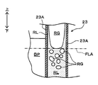
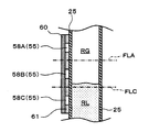
- FIG. 2 shows the inside of the heat exchange unit 23 when a proper amount of refrigerant is sealed in the fluid circulation circuit 10 when the battery pack BP is cooled.
- the appropriate liquid surface position FLA indicates the position of the liquid surface of the liquid-phase refrigerant in the heat exchanger 20 for the device, when the amount of refrigerant sealed in the fluid circulation circuit 10 is appropriate.
- the heat exchange unit 23 of the device heat exchanger 20 is configured of a plurality of tubes 23A. Therefore, the side surface of the battery cell BC which comprises the assembled battery BP is in thermal contact with the outer surface of each tube 23A.
- each tube 23A constitutes a part of the fluid circulation circuit 10
- the inside of the tube 23A constitutes a flow path of a refrigerant which is a working fluid.
- the liquid phase refrigerant RL is present on the lower side in the direction of gravity in the tube 23A, and the gas phase refrigerant RG is present on the upper side.
- the heat generated in the battery cell BC is transferred to the refrigerant inside the tube 23A through the tube 23A constituting the heat exchange portion 23. .
- the liquid phase refrigerant RL boils and changes in phase to a gas phase refrigerant RG.
- the battery cells BC constituting the battery pack BP are cooled by the latent heat of vaporization of the liquid phase refrigerant RL at this time.
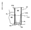
- the liquid phase refrigerant RL boils and changes its phase to a gas phase refrigerant RG.
- bubbles of the gas phase refrigerant RG generated by the boiling are repelled on the liquid surface of the liquid phase refrigerant RL.
- the liquid level of the liquid-phase refrigerant RL is located below the appropriate liquid level FLA. For this reason, unlike the case shown in FIG. 2, a portion not wetted by the liquid phase refrigerant RL is generated on the upper side in the direction of gravity of the inner wall surface of each tube 23A.
- each tube 23A which is not wetted by the liquid-phase refrigerant RL is heated by the heat of the battery pack BP to raise its temperature. Further, a portion of the tube 23A not wetted by the liquid phase refrigerant RL is in contact with the gas phase refrigerant RG. Therefore, the gas phase refrigerant RG is also heated by the influence of the heat of the battery pack BP, and the temperature thereof is increased.
- the battery assembly BP is generated by the latent heat of evaporation of the liquid phase refrigerant RL as in the case of the appropriate liquid level FLA. Cooling is performed.
- the cooling performance of the assembled battery BP differs at the upper and lower sides in the direction of gravity.
- the temperature distribution of the battery surface temperature of the battery pack BP is biased in the vertical direction in the direction of gravity.
- the battery internal temperature of the battery pack BP is also biased upward and downward in the direction of gravity.
- the appropriate liquid level position FLA can be defined as the liquid level position of the liquid-phase refrigerant RL that can wet the entire inner wall surface of the heat exchange unit 23 in the apparatus heat exchanger 20 with the liquid-phase refrigerant RL.
- the amount of refrigerant charged into the fluid circulation circuit 10 at that time can be defined as the appropriate amount sealed.
- the appropriate enclosed amount is an example of a reference amount.
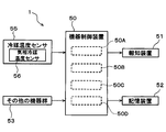
- the device control device 50 is configured of a known microcomputer including a CPU, a ROM, a RAM, and the like, and peripheral circuits thereof.
- the device control device 50 performs various operations and processing based on the control program stored in the ROM.
- a refrigerant temperature sensor 55 is connected to the input side of the device control device 50.
- the refrigerant temperature sensor 55 detects a physical quantity that has a correlation with the temperature of the refrigerant that is the working fluid sealed in the fluid circulation circuit 10.
- the refrigerant temperature sensor 55 corresponds to a physical quantity detection unit.
- a gas phase refrigerant temperature sensor 56 is connected as the refrigerant temperature sensor 55. That is, the refrigerant temperature sensor 55 includes the gas phase refrigerant temperature sensor 56.
- the gas-phase refrigerant temperature sensor 56 detects a physical quantity that has a correlation with the temperature of the gas-phase refrigerant inside the fluid circulation circuit 10 as a gas-phase physical quantity. That is, the gas phase refrigerant temperature sensor 56 corresponds to a gas phase physical quantity detection unit.
- the gas-phase refrigerant temperature sensor 56 As shown in FIG. 1, the gas-phase refrigerant temperature sensor 56 according to the first embodiment is disposed on the surface of the heat exchange unit 23 in the device heat exchanger 20.
- the gas phase refrigerant temperature sensor 56 is disposed on the heat exchange section 23 above the appropriate liquid surface position FLA in the direction of gravity.
- the gas phase refrigerant temperature sensor 56 is arranged as described above because the evaporated gas phase refrigerant flows above the appropriate liquid surface position FLA in the heat exchange unit 23. By doing this, the surface temperature of the heat exchanger 23 can be detected as a physical quantity that has a correlation with the temperature of the gas phase refrigerant.
- the gas phase refrigerant temperature sensor 56 is disposed at a position close to the upper end of the battery pack BP which is the target device in the heat exchange unit 23. By arranging in this manner, it is possible to ensure a long heating period of the gas phase refrigerant flowing upward inside the heat exchange unit 23 by the heat of the battery pack BP until the detection by the gas phase refrigerant temperature sensor 56. That is, the gas phase refrigerant temperature sensor 56 can detect a large temperature change of the gas phase refrigerant.
- the gas phase refrigerant temperature sensor 56 estimates or calculates the temperature of the gas phase refrigerant in the inside from the surface temperature of the heat exchange unit 23 detected by the gas phase refrigerant temperature sensor 56, and calculates this as a gas phase physical quantity It may be configured to output as. Further, when disposing the gas phase refrigerant temperature sensor 56 with respect to the heat exchange portion 23, it is desirable to select a position which has little influence on the heat exchange between the refrigerant inside the heat exchange portion 23 and the assembled battery BP.
- a notification device 51 and a storage device 52 are connected to the output side of the device control device 50.
- the notification device 51 includes, for example, an audio output unit for outputting information in voice and an information display unit for visually displaying information.
- the notification device 51 can notify the user of the fact that the amount of refrigerant enclosed in the fluid circulation circuit 10 is smaller than the amount appropriately enclosed according to a control program described later.
- the notification device 51 corresponds to a notification unit.
- the storage device 52 is configured to be able to rewrite the stored content, and, for example, when the amount of filled refrigerant is smaller than the appropriate amount of enclosed, etc., history information indicating that is written.
- the other device group 53 is connected to the device control device 50.
- the other device group 53 includes a battery control device for controlling the battery pack BP and an air conditioning control device for controlling the operation of the refrigeration cycle device.
- the battery control device is connected to a current sensor that detects an output current value of the assembled battery BP, a battery temperature sensor that detects a battery temperature that is an internal temperature of the assembled battery BP, and the like. Therefore, the device control device 50 can perform input / output control of the assembled battery BP and obtain the output current value and the battery temperature of the assembled battery BP via the battery control device which is the other device group 53. .
- the constituent elements (for example, a compressor and a pressure reducing unit) in the refrigeration cycle apparatus are connected to the air conditioning control device. Further, an air conditioning sensor group is connected to the air conditioning control device.
- the air conditioning sensor group includes an outside air temperature sensor for detecting the outside air temperature Tam.
- the device control device 50 performs operation control of various components of the refrigeration cycle device and acquisition of detection values by the air conditioning sensor group via the air conditioning control device which is the other device group 53. it can.
- a control unit for controlling various control target devices connected to the output side is integrally configured, but a configuration for controlling the operation of each control target device (hardware and software ) Constitute a control unit that controls the operation of each control target device.
- the configuration for specifying the battery heat generation amount Q of the battery pack BP from various detection values is the heat generation amount specifying unit 50A.
- the heat generation amount specifying unit 50A corresponds to a heat generation amount detection unit.
- the configuration for setting the reference value for determining the decrease in the refrigerant charge amount from various detection values is the reference value setting unit 50B.
- the reference value setting unit 50B corresponds to a reference physical quantity setting unit.
- the configuration for estimating the amount of refrigerant enclosed in the fluid circulation circuit 10 is a fluid amount estimation unit 50C.
- the fluid volume estimation unit 50C corresponds to a fluid volume estimation unit.
- the configuration to determine whether the refrigerant charge amount is smaller than a predetermined amount is the decrease determination unit 50D.
- the decrease determination unit 50D corresponds to a decrease determination unit.
- the operation of the temperature control device 1 when cooling the battery pack BP will be described in detail.
- the liquid in the heat exchange unit 23 Part of the phase refrigerant evaporates due to the heat from the battery pack BP.
- the battery pack BP is cooled by the evaporation latent heat of the liquid-phase refrigerant in the heat exchanger 20 for equipment, and the temperature of the battery pack BP is lowered.
- the refrigerant changes its phase from the liquid phase to the gas phase, so its specific gravity decreases. Therefore, the gas phase refrigerant evaporated in the device heat exchanger 20 moves upward in the heat exchange unit 23 and flows out to the gas phase side piping 40 from the pipe connection portion 21A of the fluid outflow portion 21. The gas phase refrigerant flows into the condenser 30 via the gas phase side pipe 40.
- the heat of the gas phase refrigerant is dissipated to another heat medium (in the first embodiment, the low pressure refrigerant in the refrigeration cycle apparatus).
- the gas phase refrigerant is condensed in the inside of the condenser 30, and becomes a liquid phase refrigerant. Since the specific gravity of the refrigerant increases due to this phase change, the liquid-phase refrigerant condensed inside the condenser 30 flows downward from the outlet 32 of the condenser 30 in the direction of gravity by its own weight.
- the liquid-phase refrigerant flowing out of the condenser 30 moves to the pipe connection portion 22A of the liquid supply portion 22 in the heat exchanger 20 for the device via the liquid-phase side pipe 45.
- the said liquid phase refrigerant flows in into the inside of the heat exchanger 20 for apparatuses from piping connection part 22A.
- the temperature of the battery pack BP is higher than the boiling point of the refrigerant, the liquid phase refrigerant in the device heat exchanger 20 is evaporated by the heat from the battery pack BP.
- the refrigerant is circulated between the heat exchanger 20 for the device and the condenser 30 while being phase-changed into the gas phase state and the liquid phase state. Heat can be transported to the condenser 30. Then, in the condenser 30, the heat of the transported refrigerant can be dissipated to the other heat medium.
- the temperature adjustment device 1 can dissipate the heat of the battery pack BP absorbed by the device heat exchanger 20 to another heat medium in the condenser 30 via the refrigerant that is the working fluid,
- the battery pack BP can be cooled.
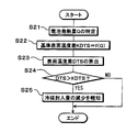
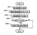
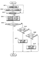
- a control process performed by the device control device 50 when the battery pack BP is cooled will be described with reference to FIG.
- the control process shown in the flowchart of FIG. 5 is realized by reading out the control program stored in the ROM of the device control device 50 and executing the control program by the device control device 50.
- Each step of the control processing constitutes a function realizing unit for realizing various functions executed by the temperature adjustment device 1.
- step S ⁇ b> 1 the initial surface temperature TS ⁇ b> 0 at the start of operation of the temperature adjustment device 1 is detected by the gas phase refrigerant temperature sensor 56 which is one of the refrigerant temperature sensors 55.
- the gas-phase refrigerant temperature sensor 56 is disposed on the upper surface of the heat exchange unit 23 in the device heat exchanger 20, and as described with reference to FIGS. Of the portion 23, the portion where the gas phase refrigerant is likely to be present. Accordingly, the initial surface temperature TSO corresponds to a physical quantity that has a correlation with the temperature of the gas-phase refrigerant at the initial stage of operation of the temperature adjustment device 1.
- a battery heat generation amount Q which is a heat generation amount of the battery pack BP, is specified.
- the battery heating value Q is calculated using the output current value of the assembled battery BP acquired via the battery control device which is the other device group 53, and the electrical resistance value inside the assembled battery BP.
- the device control device 50 that executes step S2 functions as a heat generation amount specification unit 50A, and corresponds to the heat generation amount specification unit.
- various methods can be employed as a method of specifying the battery heating value Q.
- a configuration may be employed in which the power is estimated from at least one state of the battery pack BP, such as the electric energy, the current value, the battery temperature, the environmental temperature, the heat quantity, and the heat capacity.
- the battery control device is configured to be capable of detecting the battery heat generation amount Q
- a configuration may be adopted in which the battery heat generation amount Q is acquired via the battery control device.
- reference surface temperature KTS is set using battery heating value Q and initial surface temperature TS0.
- the reference surface temperature KTS is used as an evaluation criterion for evaluating the amount of refrigerant enclosed in the fluid circulation circuit 10, and corresponds to a reference physical amount.
- the temperature control device 1 when a battery calorific value Q is generated in the battery pack BP which is the target device, the temperature of the battery pack BP does not rise and the input / output characteristics do not deteriorate.
- the target temperature is predetermined.
- the temperature of the liquid-phase refrigerant in the condenser 30 is adjusted. Since the liquid phase refrigerant whose temperature has been adjusted is supplied from the condenser 30 to the device heat exchanger 20, the temperature of the battery pack BP is adjusted by heat exchange with the liquid phase refrigerant in the device heat exchanger 20. There is.
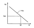
- the target surface temperature TTS is set to be smaller as the battery heat generation amount Q is larger.
- the value of the target surface temperature TTS on the upper side of the heat exchange unit 23 is specified as TSf.
- the heat radiation performance of the condenser 30 is adjusted so that the surface temperature TS on the upper side of the heat exchange unit 23 becomes the target surface temperature TTS, and the liquid phase refrigerant flowing out of the condenser 30 Temperature is also adjusted.
- a temperature change LA indicated by a solid line indicates a temperature change when the appropriate amount of the refrigerant is enclosed in the fluid circulation circuit 10, and the liquid level of the liquid-phase refrigerant in the device heat exchanger 20 is the appropriate liquid This means the temperature change in the state at the plane position FLA.
- a temperature change LC indicated by a broken line in FIG. 7 indicates a temperature change when the warning enclosed amount of refrigerant is enclosed in the fluid circulation circuit 10, and the liquid surface of the liquid-phase refrigerant in the heat exchanger 20 for equipment Means the temperature change in the state where it is in the warning liquid level FLC described later.
- the warning charge amount is a refrigerant charge amount less than the proper charge amount, and corresponds to, for example, the lower limit value of the refrigerant charge amount allowed from the viewpoint of performance maintenance and temperature uniformity of the assembled battery BP.
- the said warning enclosed quantity is an example of a reference quantity, and is equivalent to a warning reference quantity.
- the warning liquid level position FLC indicates the liquid level position of the liquid-phase refrigerant in the heat exchanger 20 for the device when the refrigerant of the warning sealing amount is sealed in the fluid circulation circuit 10.
- the temperature change of the surface temperature TS when heat is generated so that the battery calorific value Q of the assembled battery BP becomes Qf from the state of the initial surface temperature TS0 as in the above-described exemplification will be described as a specific example. As indicated by the solid line in FIG. 7, when the proper amount of the refrigerant is enclosed, the surface temperature TS becomes higher as time passes from time t0 indicating the start of heat generation of the battery pack BP.
- the surface temperature TS reaches TSf which is the above-described target surface temperature TTS.
- the surface temperature TS indicates TSn at time tn when determining the amount of refrigerant charged in the fluid circulation circuit 10.
- the surface temperature TS is a time indicating the start of heat generation of the battery pack BP, as shown by a broken line in FIG. It becomes high as time passes from t0. At this time, as time passes, the surface temperature TS shows a temperature higher than the surface temperature when the appropriate amount of encapsulation is enclosed.
- the surface temperature TS (i.e., TSn) at time tn when the appropriate enclosed amount is enclosed is defined as the reference surface temperature KTS.
- the surface temperature at time tn when the amount of the enclosed alert is enclosed is used as a reference and compared with the surface temperature TS detected by the gas phase refrigerant temperature sensor 56, it is enclosed in the fluid circulation circuit 10 at this time It can be determined whether the refrigerant charge amount is decreasing with reference to the warning charge amount.
- the reference surface temperature KTS when the appropriate amount of encapsulation is enclosed, and the reference surface temperature KTS when the amount of enclosed alert is enclosed are specified with the initial surface temperature TS0 and the battery heat generation amount Q as parameters. can do.
- a control map in which the reference surface temperature KTS, the initial surface temperature TS0, and the battery heating value Q are associated with each other is created in advance by measurement or calculation.
- the control map is stored in the ROM of the device control device 50.
- step S3 the control map stored in the ROM of the device control apparatus 50 is read, and using the initial surface temperature TS0 detected in step S1 and the battery heat generation amount Q specified in step S2, the reference surface temperature KTS Is identified.
- the device control apparatus 50 that executes step S3 functions as a reference value setting unit 50B, and corresponds to a reference physical quantity setting unit.
- the gas temperature refrigerant temperature sensor 56 detects the surface temperature TS on the upper side of the heat exchanger 23 at the present time.
- step S5 it is determined whether or not the current surface temperature TS is higher than the reference surface temperature KTS relating to the appropriate enclosed amount. If the current surface temperature TS is higher than the reference surface temperature KTS, the current amount of refrigerant enclosed is smaller than the appropriate amount enclosed, and the liquid level position of the liquid phase refrigerant in the device heat exchanger 20 is higher than the appropriate liquid level position FLA It can be estimated that it is located below.
- the refrigerant charge amount at the present time is equal to or larger than the appropriate charge amount, and the liquid level position of the liquid phase refrigerant in the heat exchanger 20 for equipment is the appropriate liquid It can be estimated that it is located at the same level as the surface position FLA or above the appropriate liquid surface position FLA. Thereafter, this control process is ended.
- the device control device 50 in the case of executing step S5 functions as the fluid amount estimating unit 50C, and corresponds to the fluid amount estimating unit.
- the device control apparatus 50 in the case of executing step S5 functions as the decrease determination unit 50D because it determines whether the amount of the current refrigerant and the appropriate amount are smaller than the appropriate amount. It corresponds to the determination unit.
- step S5 it can be determined in step S5 whether the current refrigerant enclosed amount is smaller than the warning enclosed amount. That is, it is also possible to determine whether the liquid level position of the liquid phase refrigerant in the heat exchanger 20 for equipment is located below the warning liquid level position FLC.
- step S6 a notification signal indicating that the refrigerant charge amount at the present time is smaller than the appropriate charge amount is output to the notification device 51.
- the notification device 51 notifies the user that the current amount of filled refrigerant is smaller than the appropriate amount of filling, by means of the voice output unit and the information display unit.
- step S5 If it is determined in step S5 that the amount of refrigerant charged at present is smaller than the amount of alarm charge, a warning signal indicating that is output to the notification device 51.
- the notification device 51 controls the operation of the voice output unit and the information display unit based on the warning signal, and warns that the current amount of filled refrigerant is smaller than the amount of filled warning.
- the warning in the notification device 51 be in a mode in which appealing power is higher than the notification based on the notification signal.
- the volume may be made larger than that at the time of notification.
- the display period may be made longer or the display size may be larger than at the time of notification.
- the fluid circulation circuit has a simple configuration in which the refrigerant temperature sensor 55 detects the temperature of the refrigerant that undergoes a phase change inside the fluid circulation circuit 10. The amount of refrigerant enclosed in 10 can be estimated.
- the temperature adjustment device 1 Since the control of the amount of injected refrigerant in the fluid circulation circuit 10 can be performed by estimating the amount of injected refrigerant, the temperature adjustment device 1 is used to maintain or equalize the temperature adjustment performance of the battery pack as the target device. Can contribute.
- a gas phase refrigerant temperature sensor 56 is disposed as the refrigerant temperature sensor 55, and a surface temperature TS having a correlation with the temperature of the gas phase refrigerant is detected.
- the said temperature adjustment apparatus 1 estimates the refrigerant
- the surface temperature can be detected as a physical quantity that has a correlation with the temperature of the gas-phase refrigerant with respect to the refrigerant that undergoes phase change inside the fluid circulation circuit 10, and the refrigerant filling amount serving as a reference Can be used to accurately estimate the amount of refrigerant currently charged.
- the gas phase refrigerant temperature sensor 56 is disposed above the appropriate liquid level FLA in the heat exchange section 23 of the device heat exchanger 20 in the direction of gravity. As described with reference to FIG. 2 and FIG. 3 and the like, the evaporated gas phase refrigerant flows above the appropriate liquid surface position FLA in the device heat exchanger 20. Therefore, the gas phase refrigerant temperature sensor 56 can reliably detect the surface temperature TS having a correlation with the temperature of the gas phase refrigerant.
- the battery heat generation amount Q of the battery pack BP is specified in step S2, and in step S3, the reference surface temperature KTS is set according to the battery heat generation amount Q. That is, since the temperature adjustment device 1 can change the reference for estimating the refrigerant charge amount according to the operation state of the battery pack BP, it is possible to accurately estimate the refrigerant charge amount at the present time.
- step S5 in order to determine whether or not the amount of refrigerant enclosed in the fluid circulation circuit 10 is reduced in step S5, maintenance and temperature equalization of the temperature adjustment performance for the battery pack BP Can contribute to
- step S5 when it is determined in step S5 that the refrigerant charging amount at the present time is smaller than the reference refrigerant charging amount (that is, the proper charging amount and the warning charging amount), the temperature adjustment device 1 notifies The device 51 can notify the user to that effect.
- the reference refrigerant charging amount that is, the proper charging amount and the warning charging amount
- the user can appropriately take measures (for example, for the fluid circulation circuit 10) based on the notification content of the notification device 51 with respect to the management of the amount of refrigerant enclosed in the fluid circulation circuit 10. It is possible to take care of the replenishment of the refrigerant. As a result, the temperature control device 1 can reliably contribute to the maintenance and temperature equalization of the temperature control performance for the battery pack as the target device.
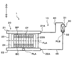
- FIG. 8 the same or equivalent parts as in the first embodiment are denoted by the same reference numerals. The same applies to the following drawings.
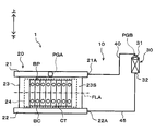
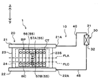
- thermosiphon-type temperature adjustment device 1 adjusts the temperature of the assembled battery BP, with the assembled battery BP mounted on a vehicle such as an electric vehicle as a target device. It is applied as a device.
- the temperature adjustment device 1 includes the fluid circulation circuit 10 and the device control device 50 as in the first embodiment.
- the fluid circulation circuit 10 is configured to include an apparatus heat exchanger 20, a condenser 30, a gas phase side pipe 40, and a liquid phase side pipe 45.
- the arrangement position of the gas phase refrigerant temperature sensor 56 constituting the refrigerant temperature sensor 55 is different from that in the first embodiment.
- the other configuration is the same as that of the first embodiment, and thus the description thereof is omitted.
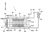
- the gas phase refrigerant temperature sensor 56 is disposed in the gas phase side pipe 40 instead of the heat exchange unit 23 of the device heat exchanger 20.
- the gas phase refrigerant temperature sensor 56 is disposed in a portion of the gas phase side piping 40 near the heat exchanger 20 for the device.
- the gas phase refrigerant temperature sensor 56 is disposed at a portion of the gas phase side piping 40 closer to the pipe connection portion 21A of the heat exchanger 20 for the device than the inlet 31 of the condenser 30 It is located on the upper side in the direction of gravity than the appropriate liquid surface position FLA.
- the gas phase refrigerant temperature sensor 56 can directly detect the temperature of the gas phase refrigerant flowing out from the pipe connection portion 21A of the fluid outflow portion 21 in the heat exchanger 20 for an apparatus. Further, the gas phase refrigerant temperature sensor 56 is connected to the input side of the device control device 50 as the refrigerant temperature sensor 55 as in the first embodiment.
- the gas phase refrigerant temperature sensor 56 according to the second embodiment corresponds to a gas phase physical quantity detection unit.
- the temperature adjustment device 1 realizes continuous cooling of the battery pack BP by natural circulation of the refrigerant without requiring a driving device such as a compressor. it can.
- the liquid surface position of the liquid phase refrigerant RL in the heat exchanger 20 for equipment is at the appropriate liquid surface position FLA, as described with reference to FIG.
- the RL wets the entire inner wall surface of the tube 23A in the vertical direction.
- the battery assembly BP can be cooled by the latent heat of vaporization of the liquid-phase refrigerant in the entire area of the heat exchange section 23 of the heat exchanger 20 for equipment.
- the refrigerant in the heat exchanger 23 causes a phase change from the liquid phase to the gas phase due to latent heat, the temperatures of the liquid phase refrigerant and the gas phase refrigerant show similar values.
- the vapor-phase refrigerant evaporated below the heat exchange unit 23 moves upward in each tube 23A due to the difference in specific gravity, and passes through a portion not wetted by the liquid-phase refrigerant RL.
- the gas phase refrigerant is heated by the heat generated in the assembled battery BP, and its temperature rises, so it becomes superheated (superheat).
- the heat generated in the battery pack BP lengthens the period during which the gas phase refrigerant is heated, and the degree of superheat of the gas phase refrigerant increases.
- the temperature control device 1 detects the temperature of the gas phase refrigerant circulating in the fluid circulation circuit 10 by the gas phase refrigerant temperature sensor 56 disposed in the gas phase side pipe 40, thereby the heat exchanger 20 for the device. It is possible to estimate the liquid level position of the liquid-phase refrigerant in the inside and the amount of refrigerant enclosed in the fluid circulation circuit 10.
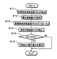
- control processing executed by the device control device 50 when cooling the battery pack BP will be described with reference to FIG.
- the control process shown in the flowchart of FIG. 9 is realized by reading out the control program stored in the ROM of the device control device 50 and executing the control program by the device control device 50.
- step S11 the initial gas phase refrigerant temperature TG0 at the start of operation of the temperature adjustment device 1 is detected by the gas phase refrigerant temperature sensor 56 which is one of the refrigerant temperature sensors 55.
- the temperature of the gas-phase refrigerant that has flowed out from the pipe connection portion 21A of the heat exchanger 20 for an apparatus to the gas-phase side pipe 40 is detected.
- step S12 as in step S2 of the first embodiment, the battery heating value Q of the battery pack BP is specified.
- the reference gas phase refrigerant temperature KTG is set using the battery heating value Q and the initial gas phase refrigerant temperature TG0.
- the reference gas phase refrigerant temperature KTG is used as an evaluation standard for evaluating the amount of refrigerant enclosed in the fluid circulation circuit 10, and corresponds to a reference physical quantity.
- the relationship between the battery heat generation amount Q, the initial gas phase refrigerant temperature TG0, and the reference gas phase refrigerant temperature KTG will be described.
- the relationship between the battery heating value Q of the assembled battery BP and the target value of the gas phase refrigerant temperature TG will be described.
- the target value of the gas phase refrigerant temperature TG is determined in accordance with the battery heating value Q.
- the target value of the gas phase refrigerant temperature TG is set to be smaller as the battery heat generation amount Q of the assembled battery BP is larger.
- the time change of the gas phase refrigerant temperature TG due to the heat generation of the assembled battery BP will be described. As described above, as the amount of the refrigerant sealed in the fluid circulation circuit 10 decreases and the liquid level position of the liquid phase refrigerant in the heat exchange unit 23 decreases, the heat generated in the battery pack BP heats the gas phase refrigerant Period will be longer.
- the gas phase refrigerant temperature TG when the liquid level in the device heat exchanger 20 is at the warning liquid level FLC is at the appropriate liquid level FLA. It is higher than the gas phase refrigerant temperature TG in one case.
- the gas phase refrigerant temperature TG at time tn can be set to the reference gas phase refrigerant temperature KTG.
- the reference gas phase refrigerant temperature KTG in the case where the appropriate enclosed amount is enclosed, and the reference gas phase refrigerant temperature KTG in the case where the alert enclosed amount is enclosed are the initial gas phase refrigerant temperature TG0 and the battery calorific value Q. Can be specified as a parameter.
- a control map in which the reference gas phase refrigerant temperature KTG, the initial gas phase refrigerant temperature TG0, and the battery heat generation amount Q are associated is created in advance by measurement or calculation. There is.
- the control map is stored in the ROM of the device control device 50.
- step S13 the control map stored in the ROM of the device control apparatus 50 is read out, and using the initial gas phase refrigerant temperature TG0 detected in step S11 and the battery heating value Q specified in step S12, the reference air The phase refrigerant temperature KTG is identified.
- the device control apparatus 50 that executes step S13 functions as a reference value setting unit 50B and corresponds to a reference physical quantity setting unit.
- the gas phase refrigerant temperature sensor 56 detects the gas phase refrigerant temperature TG of the gas phase refrigerant flowing out to the gas phase side pipe 40 at the present time.
- step S15 it is determined whether or not the gas phase refrigerant temperature TG at the present time is higher than the reference gas phase refrigerant temperature KTG relating to the appropriate enclosed amount.
- the refrigerant charge amount at the present time is smaller than the appropriate charge amount, and the liquid level position of the liquid phase refrigerant in the heat exchanger 20 for equipment is the appropriate liquid level It can be estimated that it is located below position FLA.
- the amount of refrigerant charged at the present time is equal to or larger than the amount appropriately sealed, and the liquid level position of the liquid-phase refrigerant in the heat exchanger 20 for equipment is the same as or appropriate position above the liquid level FLA. It can be estimated that Thereafter, this control process is ended.
- the device control apparatus 50 in the case of executing step S15 functions as a fluid volume estimation unit 50C and a reduction determination unit 50D as in the first embodiment, and corresponds to a fluid volume estimation unit and a reduction determination unit.
- step S16 a control signal (that is, a notification signal or a warning signal) according to the determination result of step S15 is output to the notification device 51.
- the notification device 51 notifies the user that the current amount of filled refrigerant is smaller than the appropriate amount of enclosed charge or the amount of filled in alert, by the voice output unit and the information display unit.
- this control process is ended.
- the same advantages as those of the first embodiment can be obtained from the same configuration and operation as those of the first embodiment.
- the gas phase refrigerant temperature sensor 56 is disposed in the gas phase side piping 40 at a portion near the pipe connection portion 21A of the heat exchanger 20 for equipment .
- the gas phase side pipe 40 corresponds to a portion with good workability, the workability relating to the arrangement operation and maintenance of the gas phase refrigerant temperature sensor 56 with respect to the gas phase side pipe 40 can be improved.
- the arrangement of the gas phase refrigerant temperature sensor 56 in the temperature control device 1 according to the first embodiment and the second embodiment described above can detect a physical quantity having a correlation with the temperature of the gas phase refrigerant in the fluid circulation circuit 10 And can be changed as appropriate.
- the gas phase refrigerant temperature sensor 56 as the refrigerant temperature sensor 55 can also be arranged at the arrangement position PGA or the arrangement position PGB shown in FIG.
- the arrangement position PGA indicates the fluid outlet 21 located above the heat exchanger 20 for the device.
- the gas phase refrigerant evaporated in the heat exchange unit 23 flows upward through the tubes 23 A of the heat exchange unit 23 and merges in the fluid outflow unit 21. Therefore, if the gas phase refrigerant temperature sensor 56 is arranged at the arrangement position PGA, it is possible to reliably detect the physical quantity having a correlation with the temperature of the gas phase refrigerant.
- the arrangement position PGB indicates the periphery of the inlet 31 in the condenser 30.
- the gas phase refrigerant flowing through the gas phase side pipe 40 flows into the inside of the condenser 30. Therefore, if the gas phase refrigerant temperature sensor 56 is arranged at the arrangement position PGB, it is possible to reliably detect the physical quantity having a correlation with the temperature of the gas phase refrigerant.
- the gas phase refrigerant temperature sensor 56 may be disposed at a plurality of locations in the fluid circulation circuit 10. For example, combining the first embodiment and the second embodiment described above, both the estimation of the refrigerant charge amount by the surface temperature TS and the estimation of the refrigerant charge amount by the gas phase refrigerant temperature TG in the gas phase side pipe 40 are performed It is also possible to configure it to
- thermosyphon type temperature control device 1 uses the battery pack BP mounted on a vehicle such as an electric vehicle as a target device and adjusts the temperature of the battery pack BP, as in the above-described embodiments. Applied as a device to
- the temperature adjustment device 1 includes the fluid circulation circuit 10 and the device control device 50, as in the above-described embodiments.
- the fluid circulation circuit 10 is configured to include an apparatus heat exchanger 20, a condenser 30, a gas phase side pipe 40, and a liquid phase side pipe 45.
- a liquid-phase refrigerant temperature sensor 57 is disposed as the refrigerant temperature sensor 55 instead of the gas-phase refrigerant temperature sensor 56.
- the other configuration is the same as that of the embodiment described above, and thus the description thereof is omitted.
- the liquid-phase refrigerant temperature sensor 57 As shown in FIG. 11, the liquid-phase refrigerant temperature sensor 57 according to the third embodiment is disposed on the surface of the heat exchange unit 23 in the heat exchanger 20 for the device.
- the liquid phase refrigerant temperature sensor 57 detects the surface temperature TS as a physical quantity that has a correlation with the temperature of the liquid phase refrigerant.
- the liquid phase refrigerant temperature sensor 57 is connected to the input side of the device control device 50 as the refrigerant temperature sensor 55. Therefore, the liquid phase refrigerant temperature sensor 57 corresponds to a liquid phase physical quantity detection unit. And in the heat exchange part 23, the liquid phase refrigerant temperature sensor 57 which concerns on 3rd Embodiment is arrange
- the liquid-phase refrigerant is located below the appropriate liquid surface position FLA in the heat exchange unit 23. Therefore, by disposing the liquid phase refrigerant temperature sensor 57 in this manner, the temperature of the liquid phase refrigerant can be detected via the surface temperature of the heat exchange unit 23.
- the liquid-phase refrigerant temperature sensor 57 is disposed below the appropriate liquid level FLA in the heat exchange unit 23 and as close as possible to the appropriate liquid level FLA.
- This position is a position that appears early as a temperature change of the surface temperature TS when the amount of the refrigerant charged decreases. Therefore, by disposing the liquid-phase refrigerant temperature sensor 57 at this position, it is possible to detect early the decrease in the amount of refrigerant enclosed in the fluid circulation circuit 10.
- the heat exchange unit 23 may be provided below the appropriate liquid level FLA and near the liquid supply unit 22.
- the temperature control device 1 realizes continuous cooling of the battery pack BP by natural circulation of the refrigerant without requiring a driving device such as a compressor as in the above-described embodiment. it can.
- the liquid surface position of the liquid phase refrigerant RL in the heat exchanger 20 for equipment is at the appropriate liquid surface position FLA, as described with reference to FIG.
- the RL wets the entire inner wall surface of the tube 23A in the vertical direction.
- the battery assembly BP can be cooled by the latent heat of vaporization of the liquid-phase refrigerant in the entire area of the heat exchange section 23 of the heat exchanger 20 for equipment.
- the refrigerant in the heat exchanger 23 causes a phase change from the liquid phase to the gas phase due to latent heat, the temperatures of the liquid phase refrigerant and the gas phase refrigerant show similar values.
- the vapor-phase refrigerant evaporated below the heat exchange unit 23 moves upward in each tube 23A due to the difference in specific gravity, and passes through a portion not wetted by the liquid-phase refrigerant RL.
- the gas phase refrigerant is heated by the heat generated in the assembled battery BP, and its temperature rises, so it becomes superheated (superheat).
- the liquid level position of a liquid phase refrigerant falls, and the temperature as the whole refrigerant
- the position of the liquid-phase refrigerant temperature sensor 57 changes from being in contact with the liquid-phase refrigerant to being in contact with the gas-phase refrigerant because the liquid level position is lowered.
- the temperature adjusting device 1 detects the surface temperature TS by the liquid-phase refrigerant temperature sensor 57 disposed below the appropriate liquid level FLA in the heat exchange unit 23 of the heat exchanger 20 for the device. It is possible to estimate the liquid level position of the liquid phase refrigerant in the heat exchanger 20 and the amount of the refrigerant sealed in the fluid circulation circuit 10.
- the initial surface temperature TS0 is detected by the liquid-phase refrigerant temperature sensor 57, and then the battery heating value Q of the assembled battery BP is specified.
- the contents of these processes are the same as in the first embodiment.
- the reference surface temperature KTS according to the third embodiment is set using the battery heating value Q and the initial surface temperature TS0.
- the reference surface temperature KTS according to the third embodiment is used as an evaluation criterion for evaluating the amount of refrigerant enclosed in the fluid circulation circuit 10, but is different from the reference surface temperature KTS in the first embodiment. Set as a value.
- the relationship between the battery heat generation amount Q, the initial surface temperature TS0, and the reference surface temperature KTS in the third embodiment will be described.
- the relationship between the battery heat generation amount Q of the assembled battery BP and the target value of the surface temperature TS is the same as in the first embodiment, and thus the description thereof is omitted.
- the time change of the surface temperature TS due to the heat generation of the battery pack BP will be described with reference to FIG.
- the portion cooled by the latent heat of evaporation of the liquid phase refrigerant decreases.
- the portion heated by the heat generated in the battery pack BP will increase.
- the surface temperature TS detected by the liquid phase refrigerant temperature sensor 57 is located at the warning liquid level FLC than when the liquid level of the liquid refrigerant is at the appropriate liquid level FLA. The case is higher.
- the relationship between the two surface temperatures TS does not change even after the time t0 from the time t0 indicating the start of heat generation of the battery pack BP.
- the surface temperature TS at time tn can be set to the reference surface temperature KTS.
- the reference surface temperature KTS in the case where the appropriate enclosed amount is enclosed and the reference surface temperature KTS in the case where the warning enclosed amount is enclosed specify the initial surface temperature TS0 and the battery heat generation amount Q as parameters.
- a control map in which the reference surface temperature KTS, the initial surface temperature TS0, and the battery heating value Q are associated with each other is created in advance by measurement or calculation.
- the control map is stored in the ROM of the device control device 50.
- control map stored in the ROM of the device control apparatus 50 is read out, and the reference surface temperature KTS is specified using the initial surface temperature TS0 and the battery heat generation amount Q.
- the surface temperature TS at the present time is detected by the liquid-phase refrigerant temperature sensor 57 disposed below the appropriate liquid level FLA in the heat exchange unit 23 of the heat exchanger 20 for equipment, and specified using a control map or the like It is compared with the reference surface temperature KTS.
- the current surface temperature TS is higher than the reference surface temperature KTS, the current amount of refrigerant enclosed is smaller than the appropriate amount enclosed, and the liquid level position of the liquid phase refrigerant in the device heat exchanger 20 is higher than the appropriate liquid level position FLA It is presumed to be located below.
- a control signal is output to the notification device 51, and the user of the notification device 51 indicates that the liquid surface position of the liquid-phase refrigerant is lower than the appropriate liquid surface position FLA and is smaller than the appropriate sealing amount. Will be informed.
- the temperature adjustment device 1 according to the third embodiment it is possible to obtain the same effects as those of the above-described embodiment, from the configuration and operation common to those of the above-described embodiment.
- a liquid-phase refrigerant temperature sensor 57 is disposed as the refrigerant temperature sensor 55, and a surface temperature TS having a correlation with the temperature of the liquid-phase refrigerant is detected.
- the said temperature adjustment apparatus 1 estimates the refrigerant
- the surface temperature can be detected as a physical quantity that has a correlation with the temperature of the liquid phase refrigerant with respect to the phase change refrigerant inside the fluid circulation circuit 10, and the reference refrigerant charge amount (that is, the appropriate charge amount or warning charge amount) Can be used to accurately estimate the amount of refrigerant currently charged.
- the liquid-phase refrigerant temperature sensor 57 is disposed on the heat exchange portion 23 of the heat exchanger 20 for the apparatus, at the lower side in the gravity direction of the appropriate liquid surface position FLA. As the liquid level of the liquid phase refrigerant decreases from the appropriate liquid level FLA, the surface temperature detected by the liquid phase refrigerant temperature sensor 57 changes. Therefore, the liquid phase refrigerant temperature sensor 57 can reliably detect the surface temperature TS having a correlation with the temperature of the liquid phase refrigerant.
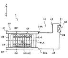
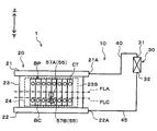
- thermosyphon type temperature control device 1 uses the battery pack BP mounted on a vehicle such as an electric vehicle as a target device and adjusts the temperature of the battery pack BP, as in the above-described embodiments. Applied as a device to
- the temperature control device 1 includes the fluid circulation circuit 10 and the device control device 50, as in the above-described embodiments.
- the fluid circulation circuit 10 is configured to include a device heat exchanger 20, a condenser 30, a gas phase side pipe 40, and a liquid phase side pipe 45.
- a liquid-phase refrigerant temperature sensor 57 is disposed as the refrigerant temperature sensor 55.
- the other configuration is the same as that of the embodiment described above, and thus the description thereof is omitted.
- the liquid-phase refrigerant temperature sensor 57 is disposed not in the heat exchange unit 23 of the device heat exchanger 20 but in the liquid-side pipe 45.
- the liquid-phase refrigerant temperature sensor 57 is disposed at a portion of the liquid-side pipe 45 close to the heat exchanger 20 for the device.
- liquid-phase refrigerant temperature sensor 57 is disposed at a portion of the liquid-phase side pipe 45 closer to the pipe connection portion 22A of the heat exchanger 20 for the device than the outlet 32 of the condenser 30 It is located lower in the direction of gravity than the appropriate liquid level FLA.
- the liquid phase refrigerant temperature sensor 57 can directly detect the temperature of the liquid phase refrigerant flowing into the pipe connection portion 22A of the liquid supply portion 22 in the heat exchanger 20 for the apparatus.
- the liquid-phase refrigerant temperature sensor 57 is connected to the input side of the device control device 50 as a refrigerant temperature sensor 55.
- the liquid phase refrigerant temperature sensor 57 according to the fourth embodiment corresponds to a liquid phase physical quantity detection unit.
- the temperature control apparatus 1 realizes continuous cooling of the battery pack BP by natural circulation of the refrigerant without requiring a driving device such as a compressor as in the above-described embodiments. Can.
- liquid surface position of the liquid phase refrigerant RL in the device heat exchanger 20 is at the appropriate liquid surface position FLA, as described with reference to FIG. It becomes wet throughout the vertical direction.
- the battery assembly BP can be cooled by the latent heat of vaporization of the liquid-phase refrigerant in the entire area of the heat exchange section 23 of the heat exchanger 20 for equipment.
- the refrigerant in the heat exchange unit 23 causes a phase change from liquid phase to gas phase due to latent heat, the entire refrigerant in the fluid circulation circuit 10 exhibits a constant temperature.
- the vapor-phase refrigerant evaporated below the heat exchange portion 23 is heated by the heat generated in the assembled battery BP when moving upward, and its temperature rises, so that the superheat (superheat ) State.
- the liquid level position of a liquid phase refrigerant falls, and the temperature as the whole refrigerant
- the temperature of the liquid phase refrigerant detected by the liquid phase refrigerant temperature sensor 57 in the liquid phase side pipe 45 increases. That is, based on the detection value of the liquid phase refrigerant temperature sensor 57 disposed in the liquid phase side pipe 45, the amount of refrigerant enclosed in the fluid circulation circuit 10 and the liquid level position of the liquid phase refrigerant in the heat exchanger 20 for equipment It can be estimated.
- the temperature adjustment device 1 can estimate that the liquid level position of the liquid phase refrigerant has dropped below the appropriate liquid level position FLA, and that the amount of refrigerant charged has decreased to a corresponding amount.
- the control process executed by the device control apparatus 50 when cooling the battery pack BP is replaced with the surface temperature TS and the reference surface temperature KTS in the third embodiment.
- the second embodiment is the same as the third embodiment described above except that the control of the initial liquid phase refrigerant temperature and the control map for setting the reference liquid phase refrigerant temperature are used.
- the refrigerant charge amount as a reference (the liquid phase refrigerant temperature detected by the liquid phase refrigerant temperature sensor 57 disposed in the liquid phase side pipe 45) That is, it is possible to accurately estimate the current amount of the refrigerant charged by using the appropriate sealed amount and the warning sealed amount).
- the notification device 51 notifies the user of that fact. Therefore, according to the said temperature control apparatus 1, the refrigerant
- the same advantages as those of the above-described embodiments can be obtained from the configurations and operations common to those of the above-described embodiments.
- the liquid-phase refrigerant temperature sensor 57 is disposed in the liquid-side pipe 45 at a portion close to the pipe connection portion 22A of the heat exchanger 20 for the device.
- the temperature adjustment device 1 can improve the workability relating to the operation of arranging the liquid-phase refrigerant temperature sensor 57 with respect to the liquid-phase side pipe 45 and maintenance.
- the arrangement of the liquid-phase refrigerant temperature sensor 57 in the temperature adjustment device 1 according to the third embodiment or the fourth embodiment described above can detect a physical quantity having a correlation with the temperature of the liquid-phase refrigerant in the fluid circulation circuit 10 And can be changed as appropriate.
- the liquid-phase refrigerant temperature sensor 57 as the refrigerant temperature sensor 55 can also be arranged at the arrangement position PLA or the arrangement position PLB shown in FIG.
- the arrangement position PLA indicates the liquid supply unit 22 located below the device heat exchanger 20.
- the liquid-phase refrigerant that has passed through the liquid-phase side pipe 45 flows from the pipe connection portion 22A into the liquid supply portion 22 of the heat exchanger 20 for the device. Therefore, by disposing the liquid-phase refrigerant temperature sensor 57 at the arrangement position PLA, it is possible to reliably detect a physical quantity that has a correlation with the temperature of the liquid-phase refrigerant.
- the arrangement position PLB indicates the periphery of the outlet 32 in the condenser 30.
- the liquid phase refrigerant condensed in the condenser 30 flows out to the liquid phase side pipe 45 at the outlet 32 of the condenser 30. Therefore, by disposing the liquid-phase refrigerant temperature sensor 57 at the arrangement position PLB, it is possible to reliably detect the physical quantity having a correlation with the temperature of the liquid-phase refrigerant.
- the liquid refrigerant temperature sensor 57 may be disposed at a plurality of locations in the fluid circulation circuit 10.
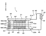
- thermosyphon type temperature control device 1 uses the battery pack BP mounted on a vehicle such as an electric vehicle as a target device and adjusts the temperature of the battery pack BP, as in the above-described embodiments. Applied as a device to
- the temperature adjustment device 1 includes the fluid circulation circuit 10 and the device control device 50, as in the above-described embodiments.
- the fluid circulation circuit 10 is configured to include an apparatus heat exchanger 20, a condenser 30, a gas phase side pipe 40, and a liquid phase side pipe 45.
- an upper liquid phase temperature sensor 57A and a lower liquid phase temperature sensor 57B are provided as the liquid phase refrigerant temperature sensor 57 which is the refrigerant temperature sensor 55.
- the other configuration is the same as that of the embodiment described above, and thus the description thereof is omitted.
- the upper liquid phase temperature sensor 57A and the lower liquid phase temperature sensor 57B are disposed on the surface of the heat exchange portion 23 in the heat exchanger 20 for the device.
- the upper liquid phase temperature sensor 57A and the lower liquid phase temperature sensor 57B detect the surface temperature TS at each arrangement position in the heat exchange unit 23 as a physical quantity having a correlation with the temperature of the liquid phase refrigerant.
- the upper liquid phase temperature sensor 57A and the lower liquid phase temperature sensor 57B are connected to the input side of the device control device 50 as the refrigerant temperature sensor 55.
- the upper liquid phase temperature sensor 57A corresponds to a liquid phase physical quantity detection unit and corresponds to an upper liquid phase physical quantity detection unit.
- the lower liquid phase temperature sensor 57B corresponds to a liquid phase physical quantity detection unit and to a lower liquid phase physical quantity detection unit.
- the upper liquid phase temperature sensor 57A is disposed, in the heat exchange section 23, on the upper side in the gravity direction of the warning liquid level FLC defined below the appropriate liquid level FLA.
- the warning liquid level position FLC corresponds to the warning reference position.
- the upper liquid phase temperature sensor 57A is the upper side in the gravity direction of the warning liquid level FLC in the heat exchange unit 23, and the lower side in the gravity direction than the proper liquid level FLA It is arranged at a position near the position FLA.
- the lower liquid phase temperature sensor 57B is disposed on the heat exchange unit 23 below the warning liquid level FLC in the gravity direction. More preferably, the lower liquid phase temperature sensor 57B is disposed below the warning liquid level FLC in the heat exchange section 23 in the direction of gravity and as close as possible to the warning liquid level FLC.
- This position is a position which appears early as a temperature change of the surface temperature TS, when the amount of charged refrigerant is smaller than the amount of charged warning related to the warning liquid level FLC. Therefore, by disposing the lower liquid phase temperature sensor 57B at this position, it is possible to detect early that the amount of refrigerant enclosed in the fluid circulation circuit 10 is smaller than the amount of alarm enclosed.
- the temperature control device 1 realizes continuous cooling of the battery pack BP by natural circulation of the refrigerant without requiring a driving device such as a compressor as in the above-described embodiment. it can.
- the portion to be cooled by the latent heat of vaporization of the liquid phase refrigerant decreases.
- the portion heated by the heat generated in the assembled battery BP is increased.
- the arrangement position of the upper liquid phase temperature sensor 57A contacts the gas phase refrigerant from the state of being in contact with the liquid phase refrigerant It will change to the state.
- the temperature control device 1 executes the control processing according to the third embodiment described above using the surface temperature TS detected by the upper liquid phase temperature sensor 57A, thereby circulating the fluid. It is possible to determine whether the amount of refrigerant charged in the circuit 10 decreases from the appropriate amount and the liquid level position of the liquid-phase refrigerant falls from the appropriate liquid level FLA. Since this point has already been described in the third embodiment, the description thereof will not be repeated.
- the liquid level position of the liquid-phase refrigerant in the heat exchanger 20 for equipment becomes the warning liquid level position FLC.
- the arrangement position of the upper liquid phase temperature sensor 57A is in contact with the gas phase refrigerant
- the arrangement position of the lower liquid phase temperature sensor 57B is in contact with the liquid phase refrigerant.
- the surface temperature TS detected by the upper liquid phase temperature sensor 57A indicates a temperature higher than the surface temperature TS detected by the lower liquid phase temperature sensor 57B.
- the temperature adjusting device 1 can measure the liquid in the heat exchanger 20 for the device based on the warning liquid level FLC. The liquid level position of the phase refrigerant can be estimated.
- a temperature difference between the surface temperature TS by the upper liquid phase temperature sensor 57A and the surface temperature TS by the lower liquid phase temperature sensor 57B is referred to as a surface temperature difference DTS. Since the surface temperature difference DTS is used, the arrangement position of the upper liquid phase temperature sensor 57A is preferably in a state where it does not get wet with the liquid phase refrigerant due to the boiling of the liquid phase refrigerant.
- the estimation of the liquid level position of the liquid-phase refrigerant using the surface temperature difference DTS is particularly effective when the battery heat generation amount Q of the battery pack BP which is the target device is small to some extent.
- the control process shown in the flowchart of FIG. 16 is realized by reading out the control program stored in the ROM of the device control device 50 and executing the control program by the device control device 50.
- the control process shown in FIG. 16 shows control contents for determining whether the amount of refrigerant charged in the fluid circulation circuit 10 is smaller than the amount of warning charge. As described above, the control process in the third embodiment is executed as to whether or not the refrigerant charge amount has decreased below the appropriate charge amount.
- step S21 the battery heating value Q of the battery pack BP is specified as in step S2 of the first embodiment.
- a reference surface temperature difference KDTS is set as a reference physical quantity corresponding to the surface temperature difference DTS using the battery heating value Q of the battery pack BP.
- the reference surface temperature difference KDTS is used as an evaluation standard for evaluating the amount of refrigerant enclosed in the fluid circulation circuit 10, and corresponds to a reference warning difference amount.
- the temperature change LA indicated by the solid line indicates the temperature change when the liquid level of the liquid-phase refrigerant in the heat exchanger 20 for equipment is at the appropriate liquid level FLA
- the temperature change LC indicated by the broken line show the temperature change in case the liquid level position of the liquid phase refrigerant
- the arrangement positions of the upper liquid phase temperature sensor 57A and the lower liquid phase temperature sensor 57B are both in contact with the liquid phase refrigerant State.
- the liquid-phase refrigerant evaporates to cause a change in latent heat, so the surface temperature difference DTS in this case is the time when the battery pack BP starts generating heat. Even if time passes from t0, the initial surface temperature difference DTS0 at time t0 is maintained.
- the arrangement position of the upper liquid phase temperature sensor 57A is in a state of being in contact with the gas phase refrigerant.
- the arrangement position of the phase temperature sensor 57B is in a state of being in contact with the liquid phase refrigerant.
- the surface temperature detected by the lower liquid phase temperature sensor 57B is a latent heat change due to the evaporation of the liquid phase refrigerant, and therefore, shows a constant value.
- the surface temperature detected by the upper liquid phase temperature sensor 57A is raised by the heat generated by the battery pack BP because the latent heat of vaporization by the liquid phase refrigerant does not act.
- the surface temperature difference DTS when the liquid level position of the liquid-phase refrigerant in the heat exchanger 20 for equipment is at the warning liquid level position FLC is larger as time passes from time t0 when the assembled battery BP starts heat generation. Indicates a value.
- DTS n which is the surface temperature difference at time t n when the determination regarding the refrigerant charge amount is performed can be specified, and this value can be set to the reference surface temperature difference KDTS. That is, the reference surface temperature difference KDTS when the warning enclosed amount is enclosed can be specified using the battery heat generation amount Q as a parameter.
- a control map in which the reference surface temperature difference KDTS is associated with the battery heating value Q is created in advance by measurement or calculation.
- the control map is stored in the ROM of the device control device 50.
- step S22 the control map stored in the ROM of the device control apparatus 50 is read out, and the reference surface temperature difference KDTS is specified using the battery heat generation amount Q specified in step S21.
- the device control apparatus 50 that executes step S22 functions as a reference value setting unit 50B and corresponds to a reference physical quantity setting unit.
- the upper liquid phase temperature sensor 57A and the lower liquid phase temperature sensor 57B detect the surface temperature TS at each position. And surface temperature difference DTS in heat exchange part 23 of heat exchanger 20 for apparatus at present is computed from two detected surface temperature TS.
- step S24 it is determined whether or not the current surface temperature difference DTS is higher than the reference surface temperature difference KDTS related to the warning enclosed amount.
- the current surface temperature difference DTS is higher than the reference surface temperature difference KDTS, the current refrigerant charge amount is smaller than the warning charge amount, and the liquid level position of the liquid-phase refrigerant in the heat exchanger 20 for equipment is the warning liquid level position FLC It can be estimated that it is located lower than it.
- the current refrigerant charge amount is equal to or larger than the warning charge amount, and the liquid level position of the liquid phase refrigerant in the device heat exchanger 20 is the same as the warning liquid level FLC or above the warning liquid level FLC. It can be estimated that Thereafter, this control process is ended.
- the device control apparatus 50 in the case of executing step S24 functions as the fluid volume estimation unit 50C and the decrease determination unit 50D as in the above-described embodiment, and corresponds to the fluid volume estimation unit and the decrease determination unit.
- step S25 a warning signal output according to the determination result of step S24 is output to the notification device 51.
- the notification device 51 notifies the user that the current refrigerant charge amount is smaller than the warning charge amount by the voice output unit and the information display unit.
- the same advantages as those of the above-described embodiments can be obtained from the same configuration and operation as those of the above-described embodiments.
- the temperature adjustment device 1 has an upper liquid phase temperature sensor 57A and a lower liquid phase temperature sensor 57B as the liquid phase refrigerant temperature sensor 57.
- the upper liquid phase temperature sensor 57A is arranged above the warning liquid level FLC in the heat exchange section 23 in the direction of gravity
- the lower liquid phase temperature sensor 57B is in the heat exchange section 23 at the warning liquid level FLC. It is arranged on the lower side in the direction of gravity.
- the liquid level position of the liquid phase refrigerant at the present time point is estimated based on the warning liquid level position FLC. Can.
- both the upper liquid phase temperature sensor 57A and the lower liquid phase temperature sensor 57B are disposed below the appropriate liquid level FLA in the heat exchange unit 23. Therefore, according to the said temperature control apparatus 1, the liquid level position of the liquid phase refrigerant
- the liquid level of the liquid-phase refrigerant in the heat exchanger 20 for the device is estimated using the two references of the appropriate liquid level position FLA and the warning liquid level position FLC. It is possible to control the amount of refrigerant charged in the fluid circulation circuit 10 in more detail.
- thermosyphon type temperature adjustment device 1 uses the battery pack BP mounted on a vehicle such as an electric vehicle as a target device and adjusts the temperature of the battery pack BP, as in the above-described embodiments. Applied as a device to
- the temperature adjustment device 1 includes the fluid circulation circuit 10 and the device control device 50, as in the above-described embodiments.
- the fluid circulation circuit 10 is configured to include a device heat exchanger 20, a condenser 30, a gas phase side pipe 40, and a liquid phase side pipe 45.
- the temperature adjustment device 1 has a gas phase refrigerant temperature sensor 56 and a liquid phase refrigerant temperature sensor 57 as the refrigerant temperature sensor 55.
- the other configuration is the same as that of the embodiment described above, and thus the description thereof is omitted.
- the vapor-phase refrigerant temperature sensor 56 is the same as the second embodiment, in the vapor-phase side piping 40, heat for equipment than the inlet portion 31 of the condenser 30. It is arrange
- the gas phase refrigerant temperature sensor 56 can directly detect the temperature of the gas phase refrigerant flowing out from the pipe connection portion 21A of the fluid outflow portion 21 in the heat exchanger 20 for an apparatus.
- the gas phase refrigerant temperature sensor 56 is connected to the input side of the device control device 50 as a refrigerant temperature sensor 55.
- liquid phase refrigerant temperature sensor 57 concerning a 6th embodiment is piping of heat exchanger 20 for apparatus rather than outlet part 32 of condenser 30 among liquid phase side piping 45 like a 4th embodiment. It is arrange
- the liquid phase refrigerant temperature sensor 57 can directly detect the temperature of the liquid phase refrigerant flowing into the pipe connection portion 22A of the liquid supply portion 22 in the heat exchanger 20 for the apparatus.
- the liquid-phase refrigerant temperature sensor 57 is connected to the input side of the device control device 50 as a refrigerant temperature sensor 55.
- the gas phase refrigerant temperature sensor 56 according to the sixth embodiment corresponds to a gas phase physical quantity detection unit
- the liquid phase refrigerant temperature sensor 57 corresponds to a liquid phase physical quantity detection unit.
- the temperature control apparatus 1 realizes continuous cooling of the battery pack BP by natural circulation of the refrigerant without requiring a driving device such as a compressor as in the above-described embodiment. it can.
- the heat exchange portion 23 is in the liquid phase over the entire vertical direction. It gets wet with the refrigerant. At this time, inside the device heat exchanger 20, the refrigerant changes its phase from the liquid phase to the gas phase due to the heat generation of the battery pack BP, so the temperatures of the liquid phase refrigerant and the gas phase refrigerant show similar values.
- the gas phase refrigerant evaporated below the heat exchange portion 23 is heated for a long time by the heat generated in the assembled battery BP as the liquid level position of the liquid phase refrigerant decreases. Therefore, as the liquid level position of the liquid phase refrigerant decreases from the appropriate liquid level position FLA, the gas phase refrigerant temperature detected by the gas phase refrigerant temperature sensor 56 rises, and the gas phase refrigerant is in a superheated (superheat) state It becomes.
- the gas phase refrigerant temperature becomes higher than the liquid phase refrigerant temperature. That is, as the liquid level position of the liquid phase refrigerant in the device heat exchanger 20 decreases, a large temperature difference occurs between the gas phase refrigerant and the liquid phase refrigerant.
- the liquid level position of the liquid phase refrigerant in the heat exchanger 20 for equipment is estimated by using the temperature difference between the gas phase refrigerant and the liquid phase refrigerant circulating in the fluid circulation circuit 10 (that is, the refrigerant temperature difference DTR described later)
- the amount of refrigerant charged in the fluid circulation circuit 10 can be estimated.
- the control process shown in the flowchart of FIG. 19 is realized by reading out the control program stored in the ROM of the device control device 50 and executing the control program by the device control device 50.
- step S31 as in step S2 of the first embodiment, the battery heating value Q of the assembled battery BP is specified.
- a reference refrigerant temperature difference KDTR is set as a reference physical quantity corresponding to the refrigerant temperature difference DTR using the battery heat generation amount Q of the assembled battery BP.
- the reference refrigerant temperature difference KDTR is used as an evaluation standard for evaluating the amount of refrigerant enclosed in the fluid circulation circuit 10, and corresponds to the reference difference.
- the refrigerant temperature difference DTR means the difference value between the gas phase refrigerant temperature detected by the gas phase refrigerant temperature sensor 56 and the liquid phase refrigerant temperature detected by the liquid phase refrigerant temperature sensor 57.
- the refrigerant temperature difference DTR corresponds to a difference physical quantity.
- the time change of the refrigerant temperature difference DTR due to the heat generation of the assembled battery BP will be described with reference to FIG.
- a temperature change LA shown by a solid line shows a temperature change when the liquid level position of the liquid phase refrigerant in the heat exchanger 20 for equipment is at the proper liquid level position FLA
- a temperature change LC shown by a broken line show the temperature change in case the liquid level position of the liquid phase refrigerant
- the temperature difference between the gas phase refrigerant and the liquid phase refrigerant shows a constant value.
- the refrigerant temperature difference at time t0 at the start of heat generation of the battery pack BP tends to be maintained.
- the value of the refrigerant temperature difference DTR also increases.
- the degree of temperature rise of the gas phase refrigerant also increases, so the degree of increase of the refrigerant temperature difference DTR also increases.
- the refrigerant temperature difference DTR when the liquid level is at the warning liquid level FLC tends to increase as time passes from time t0.
- the temporal change of the respective refrigerant temperature differences DTR The refrigerant temperature difference DTRn at the time tn when the determination regarding the refrigerant charge amount is performed can be specified respectively, and this value can be set as the reference refrigerant temperature difference.
- the reference refrigerant temperature difference KDTR in the sixth embodiment can be specified using the battery heat generation amount Q as a parameter.
- a control map in which the reference refrigerant temperature difference KDTR and the battery heating value Q are associated with each other is created in advance by measurement or calculation.
- the control map is stored in the ROM of the device control device 50.
- step S32 the control map stored in the ROM of the device control apparatus 50 is read out, and the reference refrigerant temperature difference KDTR is identified using the battery heat generation amount Q identified in step S31.
- the reference refrigerant temperature difference KDTR related to the warning enclosed amount is specified.
- the device control apparatus 50 that executes step S32 functions as a reference value setting unit 50B and corresponds to a reference physical quantity setting unit.
- the gas phase refrigerant temperature sensor 56 and the liquid phase refrigerant temperature sensor 57 detect the gas phase refrigerant temperature and the liquid phase refrigerant temperature, respectively. Then, the refrigerant temperature difference DTR at the present time is calculated from the detected gas phase refrigerant temperature and liquid phase refrigerant temperature.
- step S34 it is determined whether or not the current refrigerant temperature difference DTR is higher than the reference refrigerant temperature difference KDTR related to the warning enclosed amount.
- the refrigerant temperature difference DTR at the present time is higher than the reference refrigerant temperature difference KDTR, the refrigerant charge amount at the present time is smaller than the warning charge amount, and the liquid level position of the liquid phase refrigerant in the heat exchanger 20 for equipment is the warning liquid level position FLC It can be estimated that it is located lower than it.
- the current refrigerant charge amount is equal to or larger than the warning charge amount, and the liquid level position of the liquid phase refrigerant in the device heat exchanger 20 is the same as the warning liquid level FLC or above the warning liquid level FLC. It can be estimated that Thereafter, this control process is ended.
- the device control device 50 in the case of executing step S34 functions as the fluid volume estimation unit 50C and the decrease determination unit 50D as in the above-described embodiment, and corresponds to the fluid volume estimation unit and the decrease determination unit.
- step S35 the warning signal output according to the determination result of step S34 is output to the notification device 51.
- the notification device 51 notifies the user that the current refrigerant charge amount is smaller than the warning charge amount by the voice output unit and the information display unit.
- this control process is ended.
- step S32 if the reference refrigerant temperature difference KDTR relating to the appropriate enclosed amount is specified, and if it is compared with the refrigerant temperature difference DTR at the present time in step S34, is the refrigerant enclosed amount at the current time smaller than the appropriate enclosed amount? It is also possible to estimate whether or not.
- the temperature adjustment device 1 As described above, according to the temperature adjustment device 1 according to the sixth embodiment, it is possible to obtain the same effects as those of the above-described embodiments, from the configuration and operation common to the above-described embodiments.
- the temperature adjusting device 1 includes a gas phase refrigerant temperature sensor 56 and a liquid phase refrigerant temperature sensor 57.
- the temperature adjustment device 1 calculates the refrigerant temperature difference DTR from the gas phase refrigerant temperature detected by the gas phase refrigerant temperature sensor 56 and the liquid phase refrigerant temperature detected by the liquid phase refrigerant temperature sensor 57, and the refrigerant temperature difference DTR To estimate the liquid level position of the liquid phase refrigerant at the present time.
- the said temperature adjustment apparatus 1 utilizes the difference of the difference value of the physical quantity which has a correlation with the temperature of the liquid phase refrigerant in the fluid circulation circuit 10, and the gas phase refrigerant, and the liquid level position of the liquid phase refrigerant in the present time It can be estimated with reference to the proper liquid level FLA, the warning liquid level FLC, and the like.
- the temperature adjustment device 1 by estimating the liquid level position of the liquid phase refrigerant at the present time, it is possible to estimate the refrigerant charged amount in the fluid circulation circuit 10 at the present time, and managing the refrigerant charged amount be able to.
- the gas phase refrigerant temperature sensor 56 is disposed on the upper side in the gravity direction than the appropriate liquid level position FLA and the warning liquid level position FLC, and the liquid phase refrigerant temperature sensor 57 is an appropriate liquid It is disposed below the surface position FLA and the warning liquid surface position FLC in the direction of gravity.
- the temperature of the gas phase refrigerant circulating in the fluid circulation circuit 10 can be reliably detected by the gas phase refrigerant temperature sensor 56, and the fluid circulation temperature sensor 57 causes the fluid circulation The temperature of the liquid phase refrigerant circulating in the circuit 10 can be detected reliably.
- the gas phase refrigerant temperature sensor 56 is disposed in the gas phase side pipe 40, and the liquid phase refrigerant temperature sensor 57 is disposed in the liquid phase side piping 45.
- the gas phase side piping 40 and the liquid phase side piping 45 correspond to portions with good workability, so the arrangement of the gas phase refrigerant temperature sensor 56 with respect to the gas phase side piping 40 and the liquid phase side piping 45
- coolant temperature sensor 57, and maintenance can be improved.
- the arrangement of the gas phase refrigerant temperature sensor 56 and the liquid phase refrigerant temperature sensor 57 is merely an example.
- the arrangement of the gas phase refrigerant temperature sensor 56 can be appropriately changed as long as it can detect a physical quantity that has a correlation with the temperature of the gas phase refrigerant in the fluid circulation circuit 10.
- the gas phase refrigerant temperature sensor 56 can be disposed at the placement position PGA or the placement position PGB shown in FIG.
- the arrangement position PGA and the arrangement position PGB have already been described with reference to FIG.
- gas phase refrigerant temperature sensor 56 may be arranged at the arrangement position PGC shown in FIG.
- the arrangement position PGC indicates the gravity direction upper side of at least the appropriate liquid surface position FLA in the heat exchange unit 23 of the heat exchanger 20 for the device.
- the arrangement position PGC be a position above the appropriate liquid surface position FLA in the heat exchange unit 23 and close to the upper end of the battery pack BP that is the target device.
- the arrangement of the liquid phase refrigerant temperature sensor 57 can be appropriately changed as long as it is possible to detect a physical quantity having a correlation with the temperature of the liquid phase refrigerant in the fluid circulation circuit 10.
- liquid-phase refrigerant temperature sensor 57 at the disposition position PLA or the disposition position PLB shown in FIG.
- the arrangement position PLA and the arrangement position PLB have already been described with reference to FIG.
- liquid phase refrigerant temperature sensor 57 in arrangement position PLC shown in FIG.
- the arrangement position PLC indicates the lower side in the gravity direction than at least the appropriate liquid surface position FLA in the heat exchange unit 23 of the heat exchanger 20 for the device.
- the arrangement position PLC be a portion below the appropriate liquid surface position FLA in the heat exchange unit 23 and further below the lower end of the assembled battery BP.
- the gas phase refrigerant temperature sensor 56 is arranged at any one of the arrangement position PGA to the arrangement position PGC shown in FIG. 21 and the liquid phase refrigerant temperature sensor is arranged at any one position of the arrangement position PLA to the arrangement position PLA.
- 57 may be arranged. The combination of the arrangement positions can be changed as appropriate.
- thermosyphon type temperature adjustment device 1 uses the battery pack BP mounted in a vehicle such as an electric vehicle as a target device and adjusts the temperature of the battery pack BP, as in the above-described embodiments. Applied as a device to
- the temperature adjustment device 1 includes the fluid circulation circuit 10 and the device control device 50, as in the above-described embodiments.
- the fluid circulation circuit 10 is configured to include an apparatus heat exchanger 20, a condenser 30, a gas phase side pipe 40, and a liquid phase side pipe 45.
- the temperature control apparatus includes, as the refrigerant temperature sensor 55, a gas phase refrigerant temperature sensor 56 and a liquid phase refrigerant temperature sensor 57.
- the liquid phase refrigerant temperature sensor 57 according to the seventh embodiment includes an upper liquid phase temperature sensor 57A and a lower liquid phase temperature sensor 57B.
- the other configuration is the same as that of the embodiment described above, and thus the description thereof is omitted.
- the gas phase refrigerant temperature sensor 56 is a heat exchange portion 23 of the heat exchanger 20 for an apparatus, which is a gravity direction upper side with respect to the appropriate liquid level FLA. It is arrange
- the gas-phase refrigerant temperature sensor 56 detects the temperature of the gas-phase refrigerant evaporated inside the device heat exchanger 20. Therefore, the gas phase refrigerant temperature sensor 56 corresponds to a gas phase physical quantity detection unit.
- the upper liquid phase temperature sensor 57A is disposed below the appropriate liquid surface position FLA in the direction of gravity in the heat exchange section 23 of the heat exchanger 20 for equipment, and above the warning liquid surface position FLC in the direction of gravity. ing.
- the warning liquid level FLC according to the seventh embodiment corresponds to a warning reference position.
- the upper liquid phase temperature sensor 57A detects the temperature of the liquid phase refrigerant inside the heat exchanger 20 for the device. Therefore, the upper liquid phase temperature sensor 57A corresponds to one of the liquid phase physical quantity detection unit and corresponds to the upper liquid phase physical quantity detection unit.
- the lower liquid phase temperature sensor 57B is disposed below the warning liquid level FLC in the direction of gravity in the heat exchange unit 23 of the heat exchanger 20 for the device.
- the lower liquid phase temperature sensor 57 ⁇ / b> B detects the temperature of the liquid phase refrigerant on the lower side of the heat exchange unit 23 inside the device heat exchanger 20. Accordingly, the lower liquid phase temperature sensor 57B corresponds to the liquid phase physical quantity detection unit and to the lower liquid phase physical quantity detection unit.
- the temperature control device 1 realizes continuous cooling of the battery pack BP by natural circulation of the refrigerant without requiring a driving device such as a compressor as in the above-described embodiment. it can.
- coolant temperature sensor 56 and the upper liquid phase temperature sensor 57A shows the tendency similar to the graph shown in FIG. That is, the refrigerant temperature difference between the gas phase refrigerant temperature sensor 56 and the upper liquid phase temperature sensor 57A with the passage of time as the liquid level position of the liquid phase refrigerant in the heat exchanger 20 for equipment falls below the appropriate liquid level FLA. Becomes larger.
- the same tendency is indicated for the temporal change of the refrigerant temperature difference by the upper liquid phase temperature sensor 57A and the lower liquid phase temperature sensor 57B. That is, the refrigerant temperature in the upper liquid phase temperature sensor 57A and the lower liquid phase temperature sensor 57B with the passage of time as the liquid level position of the liquid phase refrigerant in the device heat exchanger 20 falls below the warning liquid level position FLC. The difference tends to increase.
- the refrigerant temperature difference between the upper liquid phase temperature sensor 57A and the lower liquid phase temperature sensor 57B corresponds to the difference liquid phase physical quantity.
- the refrigerant temperature difference at time tn can be identified from the temporal change of the refrigerant temperature difference by the gas phase refrigerant temperature sensor 56 and the upper liquid phase temperature sensor 57A, and the liquid level of the liquid phase refrigerant is at the appropriate liquid level position FLA.
- the reference refrigerant temperature difference in a certain case can be identified.
- the refrigerant temperature difference at time tn can be specified from the temporal change of the refrigerant temperature difference by the upper liquid phase temperature sensor 57A and the lower liquid phase temperature sensor 57B.
- coolant exists in warning liquid level position FLC can be specified.
- the reference refrigerant temperature difference relating to the appropriate sealing amount and the reference refrigerant temperature difference relating to the warning sealing amount using the battery heat generation amount Q as a parameter.
- the reference refrigerant temperature difference relating to the warning enclosed amount corresponds to the reference warning difference amount.
- a control map in which the reference refrigerant temperature difference relating to the appropriate enclosed amount and the battery heat generation amount Q are associated, the reference refrigerant temperature difference relating to the warning enclosed amount, and the battery generated amount Q And control maps associated with each other are created in advance by measurement or calculation.
- the control maps are all stored in the ROM of the device control apparatus 50.
- the refrigerant temperature difference at the present time by the gas phase refrigerant temperature sensor 56 and the upper liquid phase temperature sensor 57A is compared with the reference refrigerant temperature difference related to the appropriate filling amount.
- the reference refrigerant temperature difference related to the appropriate filling amount it can be determined whether or not the liquid level of the liquid phase refrigerant at the current time point is lower than the appropriate liquid level position FLA.
- the temperature adjustment device 1 compares the current refrigerant temperature difference by the upper liquid phase temperature sensor 57A and the lower liquid phase temperature sensor 57B with the reference refrigerant temperature difference relating to the amount of enclosed warning, thereby the liquid at the current time. It can be determined whether the liquid level of the phase refrigerant is lower than the warning liquid level FLC and is smaller than the warning enclosed amount.
- the temperature adjustment device 1 outputs a control signal (that is, a notification signal or a warning signal) based on the determination results to the notification device 51, thereby allowing the user of the refrigerant circulation amount of the fluid circulation circuit 10 at the current time to be Can be informed or warned.
- a control signal that is, a notification signal or a warning signal
- control process in the seventh embodiment are basically the same as the flowchart shown in FIG. 19, and thus the illustration and the detailed description will be omitted.
- the same advantages as those of the above-described embodiments can be obtained from the configuration and operation common to those of the above-described embodiments.
- the temperature adjusting device 1 includes, as the refrigerant temperature sensor 55, a gas phase refrigerant temperature sensor 56, an upper liquid phase temperature sensor 57A, and a lower liquid phase temperature sensor 57B.
- the temperature adjustment device 1 uses the refrigerant temperature difference between the gas phase refrigerant temperature sensor 56 and the upper liquid phase temperature sensor 57A and the reference refrigerant temperature difference relating to the appropriate enclosed amount, and uses the appropriate liquid surface position FLA as a reference It is possible to estimate the liquid level position of the liquid phase refrigerant in
- the temperature adjustment device 1 uses the refrigerant temperature difference between the upper liquid phase temperature sensor 57A and the lower liquid phase temperature sensor 57B and the reference refrigerant temperature difference relating to the amount of enclosed warning to reference the warning liquid level FLC. As, it is possible to estimate the liquid level position of the liquid phase refrigerant at the present time.
- the temperature adjustment device 1 by estimating the liquid level position of the liquid phase refrigerant at the present time, the refrigerant charge amount in the fluid circulation circuit 10 at the present time can be estimated more accurately, and management of the refrigerant charge amount It can be performed.
- thermosyphon type temperature control device 1 uses the battery pack BP mounted on a vehicle such as an electric vehicle as a target device and adjusts the temperature of the battery pack BP, as in the above-described embodiments. Applied as a device to
- the temperature adjustment device 1 includes the fluid circulation circuit 10 and the device control device 50, as in the above-described embodiments.
- the fluid circulation circuit 10 is configured to include an apparatus heat exchanger 20, a condenser 30, a gas phase side pipe 40, and a liquid phase side pipe 45.
- the temperature adjustment device 1 according to the eighth embodiment differs from the above-described embodiment in the configuration of the device heat exchanger 20 and the refrigerant temperature sensor 55 as shown in FIG.
- the other configuration is the same as that of the embodiment described above, and thus the description thereof is omitted.
- the heat exchanger 20 for equipment according to the eighth embodiment is added to the fluid outflow portion 21, the liquid supply portion 22, the heat exchange portion 23, and the heat conduction sheet 24 configured similarly to the above-described embodiment, A detection tube 25 is provided.
- the detection tube 25 is disposed between the fluid outflow portion 21 and the liquid supply portion 22 in the direction of gravity, and is made of a metal material having excellent thermal conductivity, like the tube 23A that constitutes the heat exchange portion 23. It is formed in a tubular shape.
- the detection tube 25 connects the inside of the fluid outlet 21 and the inside of the liquid supply unit 22. Therefore, as shown in FIG. 24, the liquid level of the liquid phase refrigerant is present at the same position as the liquid level position of the liquid phase refrigerant in the heat exchange unit 23 inside the detection tube 25.
- the detection tube 25 corresponds to a detection flow path.
- a first temperature sensor 58A, a second temperature sensor 58B, and a third temperature sensor 58C are disposed on the outer peripheral surface of the detection tube 25.
- the first temperature sensor 58A to the third temperature sensor 58C are in thermal contact with the detection tube 25 at their respective arrangement positions, and are configured to detect the temperature of the refrigerant inside the detection tube 25. It is done.
- the first temperature sensor 58A to the third temperature sensor 58C are arranged side by side in the gravity direction in the detection tube 25.
- the first temperature sensor 58A is located on the detection tube 25 above the appropriate liquid surface position FLA in the heat exchanger 20 for the device in the gravity direction.
- the second temperature sensor 58B is disposed below the appropriate liquid level FLA in the heat exchanger 20 for the apparatus in the direction of gravity in the detection tube 25 and above the warning liquid level FLC in the direction of gravity. It is done. Therefore, the second temperature sensor 58B is located below the first temperature sensor 58A in the gravity direction.
- the third temperature sensor 58C is disposed below the warning liquid level FLC in the heat exchanger 20 for the device in the gravity direction in the detection tube 25. Therefore, the third temperature sensor 58C is located lower in the direction of gravity than the first temperature sensor 58A and the second temperature sensor 58B.
- the first temperature sensor 58A to the third temperature sensor 58C are connected to the input side of the device control device 50, respectively. Therefore, the first temperature sensor 58A to the third temperature sensor 58C correspond to physical quantity detection units and to a plurality of detection units, respectively.
- a sensor holder 61 is disposed on the detection tube 25 so as to cover the first temperature sensor 58A to the third temperature sensor 58C.
- the sensor holding body 61 is formed, for example, in a sheet shape having a predetermined viscosity.
- the sensor holder 61 has a function of holding the first temperature sensor 58A to the third temperature sensor 58C at predetermined positions in the detection tube 25 and a function of suppressing the thermal resistance between the heating device 60 and the detection tube 25 described later. have.
- a heating device 60 is disposed in the detection tube 25.
- the heating device 60 is composed of an electric heater that generates heat when energized, and is disposed outside the sensor holder 61.
- the heating device 60 is arranged so as to include the arrangement positions of the first temperature sensor 58A to the third temperature sensor 58C, and is configured to uniformly heat any position.
- the sensor holder 61 has a function of suppressing the thermal resistance between the heating device 60 and the detection tube 25, the heat generated by the heating device 60 is detected by the sensor holder 61 and the detection tube. The refrigerant is transmitted to the inside of the detection tube 25 through the 25 tube walls.
- the said heating apparatus 60 is comprised with the electric heater of the variable type from which emitted-heat amount changes according to the electricity supply amount.
- the amount of current supplied to the heating device 60 is controlled in accordance with a control signal from the device control device 50.
- the heating device 60 corresponds to a heating unit.
- the control process shown in the flowchart of FIG. 25 is realized by reading out the control program stored in the ROM of the device control device 50 and executing the control program by the device control device 50.
- the timing of executing the control process according to the eighth embodiment is not limited to the case of cooling the battery pack BP which is the target device.
- the control process may be performed when the vehicle is started, and may be performed at any time desired by the user.
- step S41 a heating start signal is output to the heating device 60.
- the heating device 60 heats the refrigerant in the detection tube 25 with a predetermined amount of heat.
- step S42 the refrigerant temperature inside the detection tube 25 is detected by the first temperature sensor 58A to the third temperature sensor 58C.
- step S43 it is determined whether or not a predetermined heating period has elapsed from the start of heating by the heating device 60. If the heating period has not elapsed, the process returns to step S41, and heating by the heating device 60 is continued.
- the first change amount TCA, the second change amount TCB, and the third change amount TCC are calculated using the refrigerant temperatures detected by the first temperature sensor 58A to the third temperature sensor 58C.
- the first change amount TCA refers to a change amount from the start of heating of the heating device 60 to the end of the heating period with respect to the refrigerant temperature detected by the first temperature sensor 58A.
- the second change amount TCB means a change amount from the start of heating of the heating device 60 to the end of the heating period with respect to the refrigerant temperature detected by the second temperature sensor 58B.
- the third change amount TCC means a change amount from the start of heating of the heating device 60 to the end of the heating period with respect to the refrigerant temperature detected by the third temperature sensor 58C.
- step S45 it is determined whether or not the first change amount TCA, the second change amount TCB, and the third change amount are equal.
- the fact that the first change amounts TCA and the like in the eighth embodiment are equal is not limited to the case where the values are completely the same, but includes a constant error.
- the magnitude of this error can be determined according to the amount of heat by the heating device 60, the environment of the vehicle during the heating period, and the like.
- the liquid-phase refrigerant is in contact at all at the arrangement positions of the first temperature sensor 58A to the third temperature sensor 58C. Means This is because the heat from the heating device 60 is used for the phase change of the liquid phase refrigerant at any arrangement position.
- step S45 it is determined whether the liquid level position of the liquid phase refrigerant at the current time point is located above the appropriate liquid level position FLA. If it is determined in step S45 that the first change amount TCA, the second change amount TCB, and the third change amount are equal to each other, the control process is ended because the amount of the refrigerant charged in the fluid circulation circuit 10 is sufficient.
- step S46 it is determined whether the first change amount TCA is larger than the second change amount TCB and the second change amount TCB is equal to the third change amount TCC.
- the gas-phase refrigerant is in contact with the first temperature sensor 58A
- the liquid-phase refrigerant is in contact with the second temperature sensor 58B and the third temperature sensor 58C. Do.
- the heat from the heating device 60 can not utilize the latent heat of vaporization of the liquid phase refrigerant, and raises the temperature of the gas phase refrigerant to bring it into an overheated state.
- the heat from the heating device 60 causes a change in latent heat that evaporates the liquid phase refrigerant, and therefore hardly raises the temperature of the liquid phase refrigerant .
- step S46 it is determined whether the liquid surface of the liquid-phase refrigerant in the device heat exchanger 20 is located between the arrangement position of the first temperature sensor 58A and the arrangement position of the second temperature sensor 58B. ing. In other words, it is determined whether or not the liquid level position of the liquid phase refrigerant at the present time has decreased to the appropriate liquid level position FLA.
- step S47 a notification signal is output to the notification device 51 based on the determination result of step S46.
- the notification device 51 notifies the user that the current amount of filled refrigerant is smaller than the appropriate amount of filling, by means of the voice output unit and the information display unit.
- step S48 it is determined whether the first change amount TCA is larger than the third change amount TCC and the second change amount TCB is larger than the third temperature sensor 58C.
- the determination condition is that the gas phase refrigerant is in contact at the arrangement position of the first temperature sensor 58A and the second temperature sensor 58B, and the liquid phase refrigerant is in contact at the arrangement position of the third temperature sensor 58C.
- the heat by the heating device 60 can not utilize the latent heat of vaporization of the liquid phase refrigerant, thereby raising the temperature of the gas phase refrigerant and causing overheating. Put in a state. Then, at the arrangement position of the third temperature sensor 58C, the heat from the heating device 60 changes the latent heat that evaporates the liquid phase refrigerant, so the temperature of the liquid phase refrigerant is hardly raised.
- step S48 it is determined whether or not the liquid surface of the liquid-phase refrigerant in the device heat exchanger 20 is positioned between the arrangement position of the second temperature sensor 58B and the arrangement position of the third temperature sensor 58C. ing. In other words, it is determined whether or not the liquid level position of the liquid phase refrigerant at the present time has decreased to the warning liquid level position FLC.
- step S49 a warning signal is output to the notification device 51 based on the determination result of step S48.
- the notification device 51 warns the user that the current refrigerant charge amount is smaller than the warning charge amount by the voice output unit and the information display unit.
- this control process is ended.
- the determination regarding the appropriate liquid level position FLA and the warning liquid level position FLC is performed using the first temperature sensor 58A to the third temperature sensor 58C, the present invention is not limited to this aspect. . By using at least two temperature sensors, determination regarding one reference liquid level position (for example, the appropriate liquid level FLA or the warning liquid level FLC) can be performed.
- the temperature adjustment device 1 according to the eighth embodiment it is possible to obtain, in the same manner as in the above-described embodiment, the same advantages as those of the above-described embodiment.
- the temperature adjusting device 1 has the first temperature sensor 58A to the third temperature sensor 58C as the refrigerant temperature sensor 55, and the arrangement positions of the first temperature sensor 58A to the third temperature sensor 58C are In the range which contains, the heating apparatus 60 which heats the refrigerant
- the temperature adjusting device 1 heats the refrigerant in the fluid circulation circuit 10 by the heating device 60, and uses the temperature change detected by the first temperature sensor 58A to the third temperature sensor 58C to detect the liquid level of the liquid phase refrigerant at the current time. The position can be estimated.
- first temperature sensor 58A to the third temperature sensor 58C and the heating device 60 are disposed with respect to the detection tube 25 connecting the fluid outflow portion 21 and the liquid supply portion 22 of the device heat exchanger 20.
- the temperature adjustment device 1 estimates the refrigerant charge amount using the heating device 60 and the first temperature sensor 58A to the third temperature sensor 58C while maintaining the temperature adjustment performance with respect to the battery pack BP which is the target device. It can be realized.
- the arrangement of the heating device 60 and the first temperature sensor 58A to the third temperature sensor 58C in the eighth embodiment is merely an example.
- the first temperature sensor 58A to the third temperature sensor 58C can be appropriately changed as long as the time change of the refrigerant temperature in the fluid circulation circuit 10 can be detected.
- the heating device 60 may be disposed so as to include the disposed positions of the first temperature sensor 58A to the third temperature sensor 58C as long as the refrigerant in the fluid circulation circuit 10 can be heated.
- the first temperature sensor 58A to the third temperature sensor 58C and the heating device 60 are disposed with respect to the detection tube 25 in the device heat exchanger 20, as shown in FIG. These may be disposed on the side surface of the heat exchange unit 23 of the heat exchanger 20 for equipment.
- the side surface portion of the heat exchange portion 23 is made of a metal material excellent in thermal conductivity, and the first temperature sensor 58A to the third temperature sensor 58C are in thermal contact with the side surface portion. Is located in
- the positional relationship between the appropriate liquid surface position FLA and the warning liquid surface position FLC with respect to the first temperature sensor 58A to the third temperature sensor 58C according to the first modification is the same as that of the eighth embodiment.
- the configuration and arrangement of the heating device 60 and the sensor holder 61 and the contents of the control process are also the same as in the eighth embodiment.
- a bypass flow passage 26 is disposed in the device heat exchanger 20.
- the upper end portion of the bypass flow passage 26 is connected to the pipe connection portion 21B at the fluid outflow portion 21 of the heat exchanger 20 for the device.
- the lower end of the bypass flow passage 26 is connected to the pipe connection portion 22B in the liquid supply portion 22 of the heat exchanger 20 for the device.
- the pipe connection portion 21B is disposed at the fluid outlet portion 21 at the opposite end of the pipe connection portion 21A, and the pipe connection portion 22B is disposed at the liquid supply portion 22 at the opposite end portion of the pipe connection portion 22A. It is done. That is, the bypass flow passage 26 is connected in parallel to the condenser 30 with respect to the heat exchanger 20 for the device.
- the same refrigerant as the refrigerant in the heat exchanger 20 for equipment is present inside the bypass flow passage 26, and the liquid surface is at the same position as the liquid level position of the liquid phase refrigerant in the heat exchanger 20 for equipment Will be located.
- the first temperature sensor 58A to the third temperature sensor 58C, the heating device 60, and the sensor holder 61 are disposed on the outer surface of the bypass flow path 26.
- the arrangement mode of these is the same as that of the eighth embodiment, and the detection tube 25 in FIG. 24 is a pipe constituting the bypass flow passage 26.
- the temperature adjusting device 1 according to the second modification configured as described above performs the control process of the eighth embodiment shown in FIG. 25 to obtain the same effects as the eighth embodiment described above.
- the effects can be obtained as in the eighth embodiment.
- the heating device 60 heats the liquid phase refrigerant in the bypass flow passage 26 to heat and warm up the battery pack BP which is the target device. it can.
- the liquid-phase refrigerant evaporates inside the bypass flow path 26.
- the vapor-phase refrigerant due to evaporation flows upward in the direction of gravity in the bypass flow path 26, and flows into the inside of the heat exchanger 20 for the device from the pipe connection portion 22B.
- the gas-phase refrigerant that has flowed into the device heat exchanger 20 flows through the heat exchange unit 23 in contact with the low-temperature assembled battery BP, and is condensed by heat exchange with the assembled battery BP.
- the battery pack BP is warmed up (i.e., warmed) by the latent heat of condensation of the refrigerant.
- the liquid-phase refrigerant condensed in the heat exchange portion 23 of the heat exchanger 20 for equipment flows downward through the heat exchange portion 23 by its own weight, and flows out from the pipe connection portion 22B into the bypass flow path 26.
- the temperature adjusting device 1 according to the second modification can transport the heat generated by the heating device 60 to the battery pack BP by natural circulation of the refrigerant without the need for a driving device such as a compressor.
- the assembled battery BP can be warmed up.
- each constituent device disposed in the bypass flow passage 26 is estimated as the amount of the refrigerant charged in the fluid circulation circuit 10, and the warm-up of the battery pack BP which is the target device. It can be used for
- the fluid circulation circuit is arranged by arranging the first temperature sensor 58A to the third temperature sensor 58C with respect to the bypass flow passage 26 and changing the control processing. It is also possible to realize the estimation of the refrigerant charge amount at 10.
- the condenser that radiates the heat of the gas-phase refrigerant in the fluid circulation circuit 10 to the low-pressure refrigerant of the refrigeration cycle is used as the condenser 30, it is limited to this embodiment It is not something to be done.
- the condenser various modes can be adopted as long as the heat of the gas phase refrigerant in the fluid circulation circuit 10 can be dissipated.
- an air-refrigerant heat exchanger which exchanges heat with air as a heat medium may be used, or water which exchanges heat with cooling water circulating in a cooling water circuit for cooling other devices
- a refrigerant heat exchanger may be used.
- the heat exchanger which carries out heat exchange with electronic cooling devices such as a Peltier device which generates cold by energization, as a condenser.
- the group battery BP is mentioned as an object apparatus used as the object of temperature control, it is not limited to this.
- the target device may be any device that requires cooling or warm-up of the device, and may be, for example, a motor, an inverter, a charger, or the like.
- the refrigerant temperature sensor 55 is used, but if it is a physical quantity that has a correlation with the temperature of the refrigerant that is the working fluid, another physical quantity is detected to The liquid level position, that is, the amount of charged refrigerant may be estimated.
- the pressure of the working fluid refrigerant can be mentioned.
- a refrigerant pressure sensor is disposed instead of the refrigerant temperature sensor 55 in each of the embodiments described above.
- a time average value (a section average or a moving average) may be calculated and used by using a plurality of detection values or the like.
- the initial physical quantity for example, the initial surface temperature etc.
- the battery heat generation amount Q it is also possible to use a value calculated by an average value or a moving average value of predetermined time intervals.
- coolant temperature sensor 55 was made into one each for convenience of explanation, it is not limited to this aspect.
- the respective sensors may be arranged at a plurality of places according to the condition of the refrigerant temperature to be detected. In this case, statistical processing may be performed on a plurality of detected values, and representative values such as an average value or a maximum value may be used.
- notification or warning may be performed. Specifically, notification or warning is given when the number of determinations indicating that the amount of injected refrigerant has decreased exceeds a prescribed number of times within a predetermined period such as one time of traveling from start to stop. It is good.
- notification or warning may be performed.
- the calorific value of the target device fluctuates with time, and the fluctuation range continues within a predetermined range and continues for a predetermined time or more, it is determined once that the amount of refrigerant enclosed has decreased. At the time when it is done, it may be configured to notify and warn of that.
- the vehicle cruises at a high speed and a constant speed cruise as in the embodiment described above and a case where the assembled battery BP is charged.
- the amount of fluctuation of the battery heat generation amount Q of the battery pack BP within a predetermined time is small, so sufficient determination accuracy can be ensured even with one determination.
- the voice output unit and the information display unit that constitute the notification device 51 are used to perform notification and warning that the amount of the refrigerant has decreased, but this aspect It is not limited to As a mode of notification or warning, display on an instrument panel (instrument panel), lighting of a warning light, output of a warning sound, or the like can also be used.
- the method of using the determination that the amount of the charged refrigerant is decreasing is not limited to notification or warning to the user. It is also possible to configure to be stored as a history in the RAM and the storage device 52 that constitute the device control device 50. With this configuration, the history contents can be confirmed at the time of maintenance and inspection of the vehicle, so that it is possible to take appropriate measures regarding the amount of refrigerant and the target device.
- the operation control of the battery pack BP according to the condition of the vehicle is performed based on the turning on of the start switch of the vehicle. It is not limited to
- the output of the battery pack BP is controlled to forcibly generate a predetermined battery heat generation amount Q in a predetermined period, and the refrigerant charge amount is estimated. It is also possible to configure. In this case, in each control process, the specified battery heat generation amount Q becomes a predetermined value, so that the processing load on the device control apparatus 50 can be reduced.
Landscapes
- Engineering & Computer Science (AREA)
- Life Sciences & Earth Sciences (AREA)
- Sustainable Development (AREA)
- Physics & Mathematics (AREA)
- Thermal Sciences (AREA)
- Mechanical Engineering (AREA)
- General Engineering & Computer Science (AREA)
- Secondary Cells (AREA)
Abstract
対象機器(BP)の温度を調整するサーモサイフォン式の温度調整装置(1)は、対象機器から吸熱して液相の作動流体を蒸発させる機器用熱交換器(20)と、機器用熱交換器にて蒸発した気相の作動流体を凝縮させる凝縮器(30)を備える。温度調整装置は、機器用熱交換器で蒸発した気相の作動流体を凝縮器に導く気相流路部(40)と、凝縮器にて凝縮した液相の作動流体を機器用熱交換器に導く液相流路部(45)を備える。温度調整装置は、機器用熱交換器と、凝縮器と、気相流路部と、液相流路部とを含んで構成される流体循環回路(10)の内部における作動流体の温度に相関を有する物理量を検出する物理量検出部(55)と、物理量検出部によって検出された物理量を用いて、作動流体の封入量を推定する流体量推定部(50C)を有する。
Description
本出願は、2017年11月7日に出願された日本特許出願2017-214661号に基づくもので、ここにその記載内容を援用する。
本開示は、サーモサイフォン式の温度調整装置に関する。
従来、対象機器の温度を調整する為に、ループ型のサーモサイフォン式の温度調整装置が用いられている。このような温度調整装置は、例えば、特許文献1に記載されている。
特許文献1に記載された電池温度調節装置は、電池温度調整部である蒸発器の内部において、電池からの吸熱によって、作動流体である冷媒を蒸発させると共に、蒸発した冷媒を熱媒体冷却部である凝縮器で凝縮させることで、対象機器である電池の冷却を行うように構成されている。
特許文献1のような温度調整装置においては、対象機器の熱によって熱交換器の内部の液相冷媒を蒸発させ、その蒸発潜熱により、対象機器を冷却するように構成されている。具体的には、熱交換器の内部にて対象機器からの熱が液相冷媒に伝達されると、液相冷媒が沸騰する。
この時、熱交換器の内壁面は、液相冷媒の液面の上方部分については、液相冷媒の沸騰による気泡等で濡れることになる。つまり、温度調整装置の内部に封入されている作動流体が適切な量であれば、熱交換器の内壁面をまんべんなく濡らすことができる為、対象機器全体を蒸発潜熱によって冷却することができる。
換言すると、温度調整装置における作動流体の量が適切な量ではなかった場合には、熱交換器の内壁面において、液相冷媒の沸騰による気泡等では濡れない部分が生じる場合がある。この場合、熱交換器の内壁面のうち液相冷媒で濡れていない面では、液相冷媒の蒸発が起こることはない為、対象機器を冷却することができず、いわゆるドライアウトが生じてしまう。
この為、特許文献1のような温度調整装置では、対象機器に対する温度調整性能や対象機器の故障等を防止する観点から、温度調整装置における作動流体の量を管理する必要が生じる。
しかしながら、特許文献1の温度調整装置は、温度調整装置の内部に封入されている作動流体の量を検出する構成を有していない。この為、特許文献1では、温度調整装置の内部における作動流体の量を管理することは困難であった。
本開示は、内部に封入された作動流体の流体封入量を推定可能なサーモサイフォン式の温度調整装置を提供することを目的とする。
本開示の一態様において、作動流体の液相と気相との相変化により対象機器の温度を調整するサーモサイフォン式の温度調整装置は、
対象機器の冷却時に対象機器から吸熱して液相の作動流体を蒸発させる機器用熱交換器と、
対象機器の冷却時に機器用熱交換器にて蒸発した気相の作動流体を凝縮させる凝縮器と、
機器用熱交換器における重力方向上方側に接続され、当該機器用熱交換器で蒸発した気相の作動流体を凝縮器に導く気相流路部と、
機器用熱交換器における重力方向下方側に接続され、凝縮器にて凝縮した液相の作動流体を機器用熱交換器に導く液相流路部と、
機器用熱交換器と、凝縮器と、気相流路部と、液相流路部とを含んで構成される流体循環回路の内部における作動流体の温度に相関を有する物理量を検出する物理量検出部と、
物理量検出部によって検出された物理量を用いて、当該サーモサイフォン式の温度調整装置の内部に封入されている作動流体の流体封入量を推定する流体量推定部と、を有する。
当該サーモサイフォン式の温度調整装置によれば、流体循環回路に封入された作動流体を、機器用熱交換器や凝縮器にて蒸発・凝縮させることによって循環させて、機器用熱交換器を介して対象機器に対する熱移動を行うことができる。そして、作動流体の温度に相関を有する物理量は、流体循環回路における気相の作動流体と液相の作動流体の状態と密接に関係している。
従って、当該サーモサイフォン式の温度調整装置によれば、物理量検出部で検出された物理量を用いて、流体循環回路の内部に封入されている作動流体の気相・液相の状態を推しはかることができ、流体循環回路における流体封入量を一定の精度で推定することができる。
これにより、当該サーモサイフォン式の温度調整装置は、流体循環回路における流体封入量を評価する指標をユーザに提供することができ、対象機器に対する温度調整性能を適正に維持することに貢献できる。
実施形態について図に基づいて説明する。以下の実施形態において、互いに同一もしくは均等である部分には、図中、同一符号を付してある。又、実施形態において、構成要素の一部だけを説明している場合、構成要素の他の部分に関しては、先行する実施形態において説明した構成要素を適用することができる。
以下の実施形態は、特に組み合わせに支障が生じない範囲であれば、特に明示していない場合であっても、各実施形態同士を部分的に組み合わせることができる。
(第1実施形態)
第1実施形態について、図1~図7を参照しつつ説明する。第1実施形態に係るサーモサイフォン式の温度調整装置1(以下、温度調整装置1という)は、車両に搭載された組電池BPの温度を調整する装置として適用されている。
第1実施形態について、図1~図7を参照しつつ説明する。第1実施形態に係るサーモサイフォン式の温度調整装置1(以下、温度調整装置1という)は、車両に搭載された組電池BPの温度を調整する装置として適用されている。
当該温度調整装置1が搭載される車両としては、例えば、組電池BPを電源として図示しない走行用電動モータによって走行可能な車両を挙げることができる。具体的には、電気自動車、ハイブリッド自動車の組電池BPに対して、温度調整装置1を適用することができる。
組電池BPは、直方体形状の複数の電池セルBCを積層配置した積層体で構成されており、温度調整の対象機器である。当該組電池BPにおいて、複数の電池セルBCは電気的に直列に接続されている。各電池セルBCは、充放電可能な二次電池(例えば、リチウムイオン電池、鉛蓄電池)で構成されている。
尚、電池セルBCの外形は、直方体形状に限定されるものではなく、円筒形状等の他の形状であっても良い。又、組電池BPは、電気的に並列に接続された電池セルBCを含んで構成されていてもよい。
このように構成された組電池BPは、車両の走行中等において電力供給等を行うと自己発熱する。組電池BPが自己発熱によって過度に高温になると、電池セルBCの劣化が促進されてしまう。
このことから、組電池BPの利用に際して、自己発熱が少なくなるように、電池セルBCの出力及び入力を制限する必要がある。換言すると、電池セルBCの出力及び入力を確保する為には、組電池BPを所定の温度範囲内に維持する必要がある。
又、組電池BPにおいて、各電池セルBCの温度にバラツキがあると、各電池セルBCの劣化の進行度合いに偏りが生じてしまう。当該組電池BPは、電池セルBCの直列接続体を含んでいる為、組電池BP全体の入出力特性は、各電池セルBCのうち、最も劣化が進行した電池セルBCの電池特性に応じて決定される。
即ち、各電池セルBCの劣化の進行度合いに偏りが生じた場合、組電池BP全体の入出力特性が低下してしまう。この為、組電池BPを長期間にわたって所望の性能を発揮させる為には、各電池セルBCの温度のバラツキを低減させる均温化が重要となる。
第1実施形態に係る温度調整装置1は、対象機器としての組電池BPの温度調整及び均温化を実現する為に適用されており、作動流体としての冷媒が循環する流体循環回路10と、機器制御装置50とを有している。図1等における矢印は、重力方向における上方、下方を示している。
次に、第1実施形態に係る温度調整装置1の具体的構成について、図1を参照しつつ説明する。第1実施形態に係る温度調整装置1において、流体循環回路10は、作動流体としての冷媒の蒸発及び凝縮により熱移動を行うヒートパイプであり、気相冷媒が流れる流路と、液相冷媒が流れる流路とが分離されたループ型のサーモサイフォンとして構成されている。
流体循環回路10を循環する作動流体としての冷媒は、蒸気圧縮式の冷凍サイクルで利用されるフロン系冷媒(例えば、R134a、R1234yf等)が用いられている。この作動流体としては、フロン系冷媒だけでなく、二酸化炭素等の他の冷媒や不凍液等を用いることも可能である。
当該流体循環回路10は、機器用熱交換器20と、凝縮器30と、気相側配管40と、液相側配管45を含む。流体循環回路10は、機器用熱交換器20、凝縮器30、気相側配管40及び液相側配管45を互いに接続することで、閉じられた環状の流体回路を構成している。流体循環回路10の内部には、その内部を真空排気した状態で、作動流体としての冷媒が封入されている。
機器用熱交換器20は、対象機器である組電池BPの温度調整を行う際に、機器用熱交換器20の内部の冷媒と、組電池BPとを熱交換させる熱交換器である。当該機器用熱交換器20は、対象機器である組電池BPの冷却時に、組電池BPから吸熱して液相冷媒を蒸発させる吸熱部として機能する。
図1に示すように、当該機器用熱交換器20は、流体流出部21と、液供給部22と、熱交換部23とを有している。流体流出部21、液供給部22及び熱交換部23は、例えば、アルミニウム、銅等の熱伝導性に優れた金属材料によって構成されている。
尚、流体流出部21、液供給部22、熱交換部23の構成材料としては、熱伝導性に優れた材料であれば、金属以外の材料を用いることも可能である。
流体流出部21は、熱伝導性に優れた金属により筒状に形成されており、機器用熱交換器20のうち重力方向の上方側に配置されている。組電池BPの冷却時において、当該流体流出部21は、組電池BPからの吸熱にて蒸発した気相冷媒が機器用熱交換器20の外部へ流出する部分である。
当該流体流出部21の一端部には、配管接続部21Aが配置されている。当該配管接続部21Aには、気相側配管40が接続されている。つまり、配管接続部21Aは、機器用熱交換器20における重力方向の上方側に位置している。従って、流体流出部21の内部の気相冷媒は、配管接続部21Aを介して、気相側配管40へ流出する。
一方、液供給部22は、熱伝導性に優れた金属により筒状に形成されており、機器用熱交換器20のうち流体流出部21よりも重力方向の下方側となる位置に配置されている。組電池BPの冷却時において、液供給部22は、流体循環回路10を循環する冷媒のうち、液相冷媒が機器用熱交換器20に対して供給される部分である。
当該液供給部22の一端部には、配管接続部22Aが配置されている。当該配管接続部22Aには、液相側配管45が接続されている。つまり、配管接続部22Aは、機器用熱交換器20における重力方向の下方側に位置している。従って、流体循環回路10における液相冷媒は、液供給部22の配管接続部22Aを介して、液相側配管45から機器用熱交換器20に対して供給される。
そして、機器用熱交換器20の熱交換部23は、重力方向において流体流出部21及び液供給部22の間に配置されており、対象機器である組電池BPと、作動流体である冷媒とを熱交換させる部分である。
当該熱交換部23は、流体流出部21及び液供給部22の長手方向へ並んだ複数本のチューブ23Aによって構成されている。各チューブ23Aは、熱伝導性に優れた金属材料によって筒状に形成されており、流体流出部21の内部と液供給部22内部とを接続している。従って、熱交換部23を構成する各チューブ23Aの内部にて、作動流体である冷媒は、相変化しつつ流体流出部21と液供給部22の間を流れる。
図1等に示すように、熱交換部23の外側には、電気絶縁性を有する熱伝導シート24を介して、組電池BPが配置されている。熱伝導シート24は、熱交換部23と組電池BPとの間の絶縁を保障すると共に、熱交換部23と組電池BPとの間の熱抵抗を抑えている。
当該組電池BPは、各電池セルBCにおける一つの側面が熱交換部23の電池接触面23Sに熱的に接触するように配置されている。熱交換部23の電池接触面23Sは、複数のチューブ23Aを並べて構成されている。
各電池セルBCにおける端子CTが設けられた面と反対側の面が、熱伝導シート24を介して電池接触面23Sに接触するように配置されている。組電池BPを構成する各電池セルBCは、重力方向に交差する方向に並べられている。
尚、図1においては、熱交換部23の一面側を図示しているが、その裏面側にも各電池セルBCが並べられており、熱伝導シート24を介して、裏面側にあたる電池接触面23Sに対して接触している。
そして、凝縮器30は、対象機器である組電池BPの冷却時に、機器用熱交換器20の内部で蒸発した気相冷媒を放熱させることで凝縮させる放熱部として機能する熱交換器である。
第1実施形態に係る凝縮器30は、冷媒‐冷媒コンデンサにて構成されており、流体循環回路10を流れる気相冷媒と、図示しない冷凍サイクル装置を流れる低圧冷媒を熱交換させることで、気相冷媒の熱を低圧冷媒へ放熱させている。
尚、冷凍サイクル装置は、蒸気圧縮式の冷凍サイクルを有しており、車両の車室内を空調する為に用いられている。当該冷凍サイクル装置は、圧縮機と、冷媒凝縮器と、減圧部(例えば、膨張弁)と、蒸発器とを有して構成されている。
当該凝縮器30は、例えば、アルミニウム、銅等の熱伝導性に優れた金属や合金で構成されている。尚、凝縮器30の構成材料としては、熱伝導性に優れた材料であれば、金属以外の材料を用いることも可能である。この場合に、凝縮器30のうち、少なくとも空気と熱交換する部位については、熱伝導性に優れた材料によって構成することが望ましい。
当該凝縮器30における重力方向の上方側には、流入口部31が配置されている。当該流入口部31には、気相側配管40における重力方向の上方側の端部が接続されている。従って、流入口部31では、気相側配管40を流れる気相冷媒が凝縮器30の内部へ流入する。
そして、凝縮器30における重力方向の下方側には、流出口部32が配置されている。当該流出口部32には、液相側配管45における重力方向の上方側の端部が接続されている。従って、流出口部32では、凝縮器30の内部にて冷凍サイクル装置を流れる低圧冷媒と熱交換して凝縮した液相冷媒が液相側配管45へ流出する。この液相冷媒は、低圧冷媒と温度の相関を有している。
尚、当該凝縮器30は、重力方向に対して直交する方向において、機器用熱交換器20の熱交換部23と重なり合う位置に配置されている。但し、凝縮器30は、その内部で冷媒の凝縮が可能なように、少なくとも流入口部31の位置が凝縮器30の内部における冷媒の液面よりも高くなるように構成されている。
気相側配管40は、機器用熱交換器20にて蒸発した気相冷媒を凝縮器30に導く冷媒流路である。当該気相側配管40は、気相流路部に相当する。図1に示すように、気相側配管40の一端部は、機器用熱交換器20の配管接続部21Aに接続されており、気相側配管40の他端部は、凝縮器30の流入口部31に接続されている。
そして、液相側配管45は、凝縮器30にて凝縮した液相冷媒を機器用熱交換器20に導く冷媒流路である。当該液相側配管45は、液相流路部に相当する。図1に示すように、液相側配管45の一端部は、機器用熱交換器20の配管接続部22Aに接続されており、液相側配管45の他端部は、凝縮器30の流出口部32に接続されている。尚、図1に示す気相側配管40及び液相側配管45の配管経路は、一例であり、車両への搭載性を考慮して適宜変更可能である。
当該第1実施形態に係る温度調整装置1では、組電池BPの自己発熱により電池温度が上昇していくと、機器用熱交換器20にて液状の冷媒が蒸発し始める。この時、機器用熱交換器20における液相冷媒の蒸発潜熱によって、機器用熱交換器20に熱的に接触している組電池BPが冷却される。
又、機器用熱交換器20の内部の冷媒は、蒸発によって相変化し密度が低下する。機器用熱交換器20にて蒸発した気相冷媒は、密度差によって機器用熱交換器20の内部を上方へ移動し、気相側配管40を介して凝縮器30に流入する。
凝縮器30に流入した気相冷媒は、凝縮器30にて冷凍サイクル装置の低圧冷媒に放熱することで液化する。凝縮器30にて凝縮した液相冷媒は、重力の作用によって、液相側配管45を介して再び機器用熱交換器20に流入する。
このように、当該温度調整装置1は、コンプレッサ等の駆動装置を必要とせずに、冷媒の自然循環によって、組電池BPの継続的な冷却を実現することができる。
上述したように、当該温度調整装置1は、流体循環回路10の内部にて作動流体としての冷媒を相変化させることで自然循環させ、対象機器である組電池BPの温度を調整している。
この時、機器用熱交換器20において、組電池BPとの適切な熱交換を実現させる為には、流体循環回路10の内部に対し、適正な量の冷媒が封入されていることが望ましい。冷媒の適正量としては、例えば、温度調整装置1の停止時において、熱交換部23の高さの1/2となる高さに液相冷媒の液面位置が位置する冷媒量を挙げることができる。
機器用熱交換器20における組電池BPとの熱交換と、流体循環回路10における冷媒封入量との関係性について、図2、図3を参照しつつ説明する。尚、冷媒封入量とは、流体循環回路10の内部に封入されている冷媒の量を意味しており、流体封入量に相当する。
図2は、組電池BPの冷却時において、流体循環回路10に適正な量の冷媒が封入されている場合の熱交換部23内部の様子を示している。適正液面位置FLAは、流体循環回路10に対する冷媒封入量が適正である場合に、機器用熱交換器20の内部における液相冷媒の液面の位置を示している。
上述したように、機器用熱交換器20の熱交換部23は、複数本のチューブ23Aによって構成されている。従って、各チューブ23Aの外表面には、組電池BPを構成する電池セルBCの側面が熱的に接触している。
又、各チューブ23Aは流体循環回路10の一部を構成している為、当該チューブ23Aの内部は、作動流体である冷媒の流路を構成する。チューブ23Aにおける重力方向の下方側には液相冷媒RLが存在し、上方側には気相冷媒RGが存在している。
電池セルBCが自己発熱し組電池BPの温度が上昇していくと、電池セルBCで生じた熱が熱交換部23を構成するチューブ23Aを介して、チューブ23Aの内部の冷媒に伝達される。
チューブ23Aの内部において、液相冷媒RLの温度が電池セルBCで生じた熱によって沸点を超えると、液相冷媒RLが沸騰して気相冷媒RGへと相変化する。この時の液相冷媒RLの蒸発潜熱によって、組電池BPを構成する電池セルBCは冷却される。
図2に示すように、液相冷媒RLの液面が適正液面位置FLAにある場合、液相冷媒RLが沸騰すると、液相冷媒RLの液面にて、沸騰により生じた気相冷媒RGによる気泡が弾ける。
これにより、適正液面位置FLAよりも上方に位置するチューブ23Aの内面が液相冷媒RLで濡れた状態になる。そして、液相冷媒RLの液面の下方については、チューブ23Aの内部は液相冷媒RLで満たされた状態である。
即ち、液相冷媒RLの液面が適正液面位置FLAにある場合、各チューブ23Aの内壁全体が液相冷媒RLで濡れた状態となる。この状態において、組電池BPからの熱が伝達されると、各チューブ23Aの内壁面に接している液相冷媒RLが蒸発する。即ち、機器用熱交換器20の熱交換部23全体において、液相冷媒RLの蒸発潜熱によって、組電池BPが冷却される。
次に、液相冷媒RLの液面が適正液面位置FLAよりも下方にある場合について、図3を参照して説明する。液相冷媒RLの液面が適正液面位置FLAよりも下方にある為、流体循環回路10における冷媒封入量が適正量よりも少ない状態を示している。
図2に示す場合と同様に、電池セルBCが自己発熱し組電池BPの温度が上昇していくと、電池セルBCで生じた熱が熱交換部23を構成するチューブ23Aを介して、チューブ23Aの内部の冷媒に伝達される。
チューブ23Aの内部において、液相冷媒RLの温度が電池セルBC生じた熱によって沸点を超えると、液相冷媒RLが沸騰して気相冷媒RGへと相変化する。この時、液相冷媒RLが沸騰すると、液相冷媒RLの液面にて、沸騰により生じた気相冷媒RGによる気泡が弾ける。
図3に示す場合は、液相冷媒RLの液面が適正液面位置FLAよりも下方に位置している。この為、図2に示す場合と異なり、各チューブ23Aの内壁面の重力方向上方側に、液相冷媒RLで濡れない部分が生じてしまう。
各チューブ23Aにて液相冷媒RLで濡れていない部分は、組電池BPの熱によって加熱され、その温度を上昇させる。又、チューブ23Aにおける液相冷媒RLで濡れていない部分は、気相冷媒RGに接している。従って、当該気相冷媒RGも、組電池BPの熱の影響で加熱され、その温度を上昇させてしまう。
尚、チューブ23Aの内壁面のうち液相冷媒RLで濡れている部分及び液面よりも下方においては、適正液面位置FLAにある場合と同様に、液相冷媒RLの蒸発潜熱によって組電池BPの冷却が行われる。
従って、液相冷媒RLの液面が適正液面位置FLAよりも下方に位置している場合、各チューブ23Aの壁面において、液相冷媒RLで濡れている部分と、液相冷媒RLで濡れていない部分が生じ、重力方向上下において冷媒の温度差が生じる。
この場合、機器用熱交換器20の熱交換部23にて、重力方向の上下で組電池BPの冷却性能が異なってしまう。組電池BPの電池表面温度の温度分布に、重力方向上下に偏りを生じさせてしまう。これは最終的に、組電池BPの電池内部温度についても、重力方向上下に偏りを生じさせてしまう。
図2、図3からもわかるように、流体循環回路10に対する冷媒封入量を適切に管理することは、対象機器である組電池BPの性能維時や均温化につながる為、非常に重要な事項である。
尚、適正液面位置FLAは、機器用熱交換器20における熱交換部23の内壁面全体を液相冷媒RLで濡らすことができる液相冷媒RLの液面位置と定義することができ、この時の流体循環回路10に対する冷媒封入量を適正封入量と定義することができる。当該適正封入量は、基準量の一例である。
次に、第1実施形態に係る温度調整装置1の制御系について、図4を参照しつつ説明する。機器制御装置50は、CPU、ROMおよびRAM等を含む周知のマイクロコンピュータとその周辺回路から構成されている。機器制御装置50は、ROMに記憶された制御プログラムに基づいて、各種演算、処理を行う。
図4に示すように、機器制御装置50の入力側には、冷媒温度センサ55が接続されている。冷媒温度センサ55は、流体循環回路10に封入されている作動流体である冷媒の温度に相関を有する物理量を検出する。当該冷媒温度センサ55は、物理量検出部に相当する。
第1実施形態においては、冷媒温度センサ55として、気相冷媒温度センサ56が接続されている。つまり、冷媒温度センサ55は、気相冷媒温度センサ56を含んでいる。気相冷媒温度センサ56は、流体循環回路10の内部における気相冷媒の温度に相関を有する物理量を、気相物理量として検出する。即ち、気相冷媒温度センサ56は、気相物理量検出部に相当する。
第1実施形態に係る気相冷媒温度センサ56は、図1に示すように、機器用熱交換器20における熱交換部23の表面に配置されている。当該気相冷媒温度センサ56は、熱交換部23において、適正液面位置FLAよりも重力方向上方側に配置されている。
上述したように、組電池BPの冷却時において、熱交換部23における適正液面位置FLAの上方は、蒸発した気相冷媒が流れる部分である為、気相冷媒温度センサ56をこのように配置することによって、気相冷媒の温度に相関を有する物理量として、熱交換部23の表面温度を検出できる。
より好ましくは、当該気相冷媒温度センサ56は、熱交換部23において、対象機器である組電池BPの上端に近い位置に配置されている。このように配置することで、気相冷媒温度センサ56による検出までの間において、熱交換部23の内部を上方側へ流れる気相冷媒を組電池BPの熱で加熱する期間を長く確保できる。即ち、気相冷媒温度センサ56によって、気相冷媒の大きな温度変化を検出することが可能となる為である。
尚、気相冷媒温度センサ56は、気相冷媒温度センサ56にて検出された熱交換部23の表面温度から、その内部における気相冷媒の温度を推定又は算出して、これを気相物理量として出力するように構成してもよい。又、熱交換部23に対する気相冷媒温度センサ56の配置に際して、熱交換部23の内部の冷媒と組電池BPとの熱交換に対する影響が少ない位置を選択することが望ましい。
そして、機器制御装置50の出力側には、報知装置51と、記憶装置52が接続されている。報知装置51は、例えば、情報を音声で出力する為の音声出力部、情報を視覚的に表示する為の情報表示部を含んで構成されている。
従って、当該報知装置51は、後述する制御プログラムに従って、流体循環回路10における冷媒封入量が適正封入量よりも減少した場合等において、その旨をユーザに報知することができる。当該報知装置51は、報知部に相当する。又、記憶装置52は、記憶内容を書き換え可能に構成されており、例えば、冷媒封入量が適正封入量よりも減少した場合等に、その旨を示す履歴情報が書き込まれる。
更に、機器制御装置50には、その他の機器群53が接続されている。その他の機器群53には、組電池BPを制御する為の電池制御装置や、冷凍サイクル装置の作動を制御する為の空調制御装置が含まれている。
電池制御装置には、組電池BPの出力電流値を検出する電流センサ、組電池BPの内部温度である電池温度を検出する電池温度センサ等が接続されている。従って、当該機器制御装置50は、その他の機器群53である電池制御装置を介して、組電池BPの入出力制御や、組電池BPの出力電流値及び電池温度等の取得を行うことができる。
空調制御装置には、冷凍サイクル装置における各構成機器(例えば、圧縮機や減圧部)が接続されている。又、当該空調制御装置には、空調用センサ群が接続されている。当該空調用センサ群には、外気温Tamを検出する為の外気温センサが含まれている。
これにより、当該機器制御装置50は、その他の機器群53である空調制御装置を介して、冷凍サイクル装置の各種構成機器の作動制御や、空調用センサ群による各検出値の取得を行うことができる。
尚、当該機器制御装置50では、その出力側に接続された各種制御対象機器を制御する制御部が一体に構成されているが、それぞれの制御対象機器の作動を制御する構成(ハードウェア及びソフトウェア)が、それぞれの制御対象機器の作動を制御する制御部を構成している。
例えば、機器制御装置50のうち、種々の検出値から組電池BPの電池発熱量Qを特定する為の構成は、発熱量特定部50Aである。当該発熱量特定部50Aは、発熱量検出部に相当する。
機器制御装置50のうち、種々の検出値から冷媒封入量の減少を判定する為の基準値を設定する構成は、基準値設定部50Bである。当該基準値設定部50Bは、基準物理量設定部に相当する。
又、機器制御装置50のうち、流体循環回路10の内部に封入されている冷媒封入量を推定する構成は、流体量推定部50Cである。当該流体量推定部50Cは、流体量推定部に相当する。
そして、機器制御装置50のうち、冷媒封入量が定められた量(例えば、適正封入量や後述する警告封入量)よりも減少しているか否かを判定する構成は、減少判定部50Dである。当該減少判定部50Dは、減少判定部に相当する。
次に、組電池BPを冷却する場合における温度調整装置1の作動について、詳細に説明する。図1に示すように、温度調整装置1の機器用熱交換器20では、組電池BPが電池発熱量Qで発熱し組電池BPの温度が上昇していくと、熱交換部23内部の液相冷媒の一部が組電池BPからの熱によって蒸発する。この時、組電池BPは、機器用熱交換器20における液相冷媒の蒸発潜熱によって冷却され、組電池BPの温度は低下する。
機器用熱交換器20の内部にて、冷媒は液相から気相へ相変化する為、その比重は小さくなる。従って、機器用熱交換器20にて蒸発した気相冷媒は、熱交換部23を上方へ向かって移動して、流体流出部21の配管接続部21Aから気相側配管40に流出する。当該気相冷媒は、気相側配管40を介して、凝縮器30へ流入する。
凝縮器30では、気相冷媒が有する熱が他の熱媒体(第1実施形態においては、冷凍サイクル装置における低圧冷媒)に放熱される。これにより、凝縮器30の内部において、気相冷媒が凝縮し、液相冷媒となる。この相変化によって冷媒の比重が増大する為、凝縮器30の内部で凝縮した液相冷媒は、その自重によって、凝縮器30の流出口部32から重力方向下方側へ流出する。
凝縮器30から流出した液相冷媒は、液相側配管45を介して、機器用熱交換器20における液供給部22の配管接続部22Aへ移動する。当該液相冷媒は、配管接続部22Aから機器用熱交換器20の内部に流入する。機器用熱交換器20内部の液相冷媒は、組電池BPの温度が冷媒の沸点よりも高い場合には、組電池BPからの熱によって蒸発する。
このように組電池BPの冷却時には、冷媒が気相状態と液相状態とに相変化しながら機器用熱交換器20と凝縮器30の間を循環することで、機器用熱交換器20から凝縮器30に熱を輸送することができる。そして、凝縮器30では、輸送された冷媒の熱を他の熱媒体へ放熱することができる。
即ち、当該温度調整装置1は、機器用熱交換器20で吸熱した組電池BPの熱を、作動流体である冷媒を介して、凝縮器30で他の熱媒体に放熱することができるので、組電池BPを冷却することができる。
続いて、第1実施形態に係る温度調整装置1において、組電池BPを冷却する際に機器制御装置50が実行する制御処理について、図5を参照しつつ説明する。図5のフローチャートに示す制御処理は、機器制御装置50のROMに記憶された制御プログラムを読み出して、当該機器制御装置50にて実行することで実現される。
そして、当該制御処理は、車両のスタートスイッチがオンされると、機器制御装置50によって所定の周期で実行される。尚、当該制御処理の各ステップは、温度調整装置1が実行する各種機能を実現する為の機能実現部を構成している。
図5に示すように、先ず、ステップS1においては、温度調整装置1の作動開始時における初期表面温度TS0が、冷媒温度センサ55のひとつである気相冷媒温度センサ56によって検出される。
第1実施形態において、気相冷媒温度センサ56は、機器用熱交換器20における熱交換部23の上方側の表面に配置されており、図2、図3にて説明したように、熱交換部23のうち、気相冷媒が存在し易い部位である。従って、初期表面温度TS0は、温度調整装置1の作動初期における気相冷媒の温度に相関を有する物理量に相当する。
次に、ステップS2では、組電池BPの発熱量である電池発熱量Qが特定される。具体的には、電池発熱量Qは、その他の機器群53である電池制御装置を介して取得した組電池BPの出力電流値と、組電池BP内部の電気抵抗値とを用いて算出される。ステップS2を実行する機器制御装置50は、発熱量特定部50Aとして機能しており、発熱量特定部に相当する。
尚、電池発熱量Qの特定方法としては、種々の態様を採用することができる。例えば、組電池BPの電力量、電流値、電池温度、環境温度、熱量、熱容量等の少なくとも1つの状態から推定する構成を採用しても良い。電池制御装置が電池発熱量Qを検出可能に構成されている場合、電池制御装置を介して電池発熱量Qを取得する構成を採用しても良い。
ステップS3においては、電池発熱量Qと、初期表面温度TS0とを用いて、基準表面温度KTSが設定される。当該基準表面温度KTSは、流体循環回路10の内部に封入されている冷媒封入量を評価する為の評価基準として用いられ、基準物理量に相当する。
ここで、電池発熱量Qと、初期表面温度TS0と、基準表面温度KTSとの関係性について、図6、図7を参照しつつ説明する。先ず、組電池BPの電池発熱量Qと、目標表面温度TTSとの関係について、図6を参照して説明する。
上述したように、組電池BPは、予め定められた温度範囲となるように温度調整を行う必要があり、温度範囲を超えた高温状態になると入出力特性が低下する。この為、当該温度調整装置1では、対象機器である組電池BPに或る電池発熱量Qが発生した場合、組電池BPが温度上昇して入出力特性が低下しないように、組電池BPの目標温度が予め定められている。
組電池BPの温度が目標温度以下になるように、凝縮器30における放熱性能が調整される為、凝縮器30における液相冷媒の温度が調整される。温度調整がなされた液相冷媒が凝縮器30から機器用熱交換器20に供給される為、機器用熱交換器20における液相冷媒との熱交換によって、組電池BPの温度を調整している。
組電池BPの温度が目標温度になる為には、組電池BPと機器用熱交換器20との熱抵抗を考慮して、熱交換部23の上方側における目標表面温度TTSを定める必要がある。図6に示すように、目標表面温度TTSは、電池発熱量Qが大きいほど小さくなるように定められている。例えば、作動が安定した時間tfにおける電池発熱量Qの値がQfであった場合、熱交換部23の上方側における目標表面温度TTSの値は、TSfに特定される。
尚、当該温度調整装置1においては、熱交換部23の上方側における表面温度TSが目標表面温度TTSとなるように、凝縮器30の放熱性能が調整され、凝縮器30から流出する液相冷媒の温度も調整される。
続いて、組電池BPの発熱による表面温度TSの時間変化について、図7を参照して説明する。図7において、実線で示す温度変化LAは、適正封入量の冷媒が流体循環回路10に封入されている場合の温度変化を示し、機器用熱交換器20における液相冷媒の液面が適正液面位置FLAにある状態の温度変化を意味する。
一方、図7にて、破線で示す温度変化LCは、警告封入量の冷媒が流体循環回路10に封入されている場合の温度変化を示し、機器用熱交換器20における液相冷媒の液面が後述する警告液面位置FLCにある状態の温度変化を意味する。
尚、警告封入量は、適正封入量よりも少ない冷媒封入量であって、例えば、組電池BPの性能維持や均温性の観点から許容される冷媒封入量の下限値に相当する。当該警告封入量は、基準量の一例であり、警告基準量に相当する。
そして、警告液面位置FLCは、警告封入量の冷媒が流体循環回路10内部に封入されている場合の機器用熱交換器20における液相冷媒の液面位置を示している。
上述した例示のように、初期表面温度TS0の状態から組電池BPの電池発熱量QがQfとなるように発熱した場合の表面温度TSの温度変化を具体例に挙げて説明する。図7にて実線で示すように、適正封入量の冷媒が封入されていると、表面温度TSは、組電池BPの発熱開始を示す時間t0から時間が経過するにつれて高くなっていく。
そして、作動が安定した時間tfになると、表面温度TSは、上述した目標表面温度TTSであるTSfに到達する。流体循環回路10における冷媒封入量を判定する際の時間tnにおいて、表面温度TSはTSnを示す。
一方、適正封入量よりも少ない警告封入量の冷媒が流体循環回路10内に封入されている場合、図7にて破線で示すように、表面温度TSは、組電池BPの発熱開始を示す時間t0から時間が経過するにつれて高くなっていく。この時、時間が経過するにつれて、表面温度TSは、適正封入量が封入されている場合の表面温度よりも更に高い温度を示す。
従って、適正封入量が封入されている場合の時間tnにおける表面温度TS(即ち、TSn)を基準表面温度KTSとする。当該基準表面温度KTSと、気相冷媒温度センサ56で検出した表面温度TSを比較することで、現時点で流体循環回路10に封入されている冷媒封入量が適正封入量を基準として減少しているか否かを判定することができる。
尚、警告封入量が封入されている場合の時間tnにおける表面温度を基準として用い、気相冷媒温度センサ56で検出した表面温度TSと比較すれば、現時点で流体循環回路10に封入されている冷媒封入量が警告封入量を基準として減少しているか否かを判定することができる。
このように、適正封入量が封入されている場合の基準表面温度KTSや、警告封入量が封入されている場合の基準表面温度KTSは、初期表面温度TS0と、電池発熱量Qをパラメータとして特定することができる。
当該温度調整装置1においては、基準表面温度KTSと、初期表面温度TS0と、電池発熱量Qとを関連付けた制御マップが、予め計測又は計算にて作成されている。当該制御マップは、機器制御装置50のROMに記憶されている。
図5に戻り、第1実施形態に係る制御処理において、ステップS3以後の処理について説明する。
ステップS3では、機器制御装置50のROMに記憶されている制御マップが読み出され、ステップS1で検出した初期表面温度TS0と、ステップS2で特定した電池発熱量Qを用いて、基準表面温度KTSが特定される。ステップS3を実行する機器制御装置50は、基準値設定部50Bとして機能しており、基準物理量設定部に相当する。
ステップS4に移行すると、気相冷媒温度センサ56によって、現時点における熱交換部23の上方側の表面温度TSが検出される。
続くステップS5では、現時点の表面温度TSが適正封入量に係る基準表面温度KTSよりも高いか否かが判定される。現時点の表面温度TSが基準表面温度KTSよりも高い場合、現時点の冷媒封入量が適正封入量よりも少なく、機器用熱交換器20における液相冷媒の液面位置が適正液面位置FLAよりも下方に位置していると推定できる。
一方、現時点の表面温度TSが基準表面温度KTSよりも高くない場合は、現時点の冷媒封入量が適正封入量と等しい又は多く、機器用熱交換器20における液相冷媒の液面位置が適正液面位置FLAと同じ又は適正液面位置FLAの上方に位置していると推定することができる。その後、この制御処理は終了される。
即ち、ステップS5を実行する場合の機器制御装置50は、流体量推定部50Cとして機能しており、流体量推定部に相当する。同時に、ステップS5を実行する場合の機器制御装置50は、現在の冷媒封入量と適正封入量よりも減少しているか否かを判定している為、減少判定部50Dとして機能しており、減少判定部に相当する。
尚、ステップS5で用いる基準表面温度KTSを警告封入量に係る値に設定すれば、ステップS5において、現時点の冷媒封入量が警告封入量よりも減少しているか否かを判定することができる。即ち、機器用熱交換器20における液相冷媒の液面位置が警告液面位置FLCよりも下方に位置しているか否かを判定することも可能である。
ステップS6においては、現時点の冷媒封入量が適正封入量よりも少ないことを示す報知信号が報知装置51に対して出力される。これにより、報知装置51は、音声出力部や情報表示部によって、現在の冷媒封入量が適正封入量よりも少ないことを、ユーザに報知する。報知装置51による報知を終了すると、この制御処理は終了される。
尚、ステップS5にて、現時点の冷媒封入量が警告封入量よりも少ないと判定された場合には、その旨を示す警告信号が報知装置51に対して出力される。報知装置51は、警告信号に基づいて、音声出力部や情報表示部の作動を制御し、現在の冷媒封入量が警告封入量よりも少ない旨を警告する。
この報知装置51における警告は、報知信号に基づく報知よりも訴求力の高い態様であることが望ましい。例えば、音声出力部による警告であれば、報知時よりも音量を大きくしても良い。情報表示部による警告であれば、報知時よりも表示期間を長くしたり、表示サイズを大きくしたりしてもよい。
以上説明したように、第1実施形態に係る温度調整装置1によれば、流体循環回路10の内部にて相変化する冷媒の温度を冷媒温度センサ55で検出する簡易な構成によって、流体循環回路10に封入されている冷媒封入量を推定することができる。
冷媒封入量を推定することで、流体循環回路10における冷媒封入量の管理を行うことができるので、当該温度調整装置1は、対象機器である組電池に対する温度調整性能の維持や均温化に貢献することができる。
当該温度調整装置1において、冷媒温度センサ55として、気相冷媒温度センサ56が配置されており、気相冷媒の温度に相関を有する表面温度TSが検出される。当該温度調整装置1は、気相冷媒に係る表面温度TSと、基準表面温度KTSとを比較することで、現時点の冷媒封入量を推定する。
これにより、流体循環回路10の内部にて相変化する冷媒に関して、気相冷媒の温度に相関を有する物理量として表面温度を検出でき、基準となる冷媒封入量(即ち、適正封入量や警告封入量)を用いて、現時点の冷媒封入量を精度良く推定することができる。
当該温度調整装置1において、気相冷媒温度センサ56は、機器用熱交換器20の熱交換部23において、適正液面位置FLAの重力方向上方側に配置されている。図2、図3等を用いて説明したように、機器用熱交換器20の内部における適正液面位置FLAの上方側には、蒸発した気相冷媒が流れていく。従って、当該気相冷媒温度センサ56は、気相冷媒の温度に相関を有する表面温度TSを確実に検出することができる。
当該温度調整装置1によれば、ステップS2にて組電池BPの電池発熱量Qを特定し、ステップS3にて、電池発熱量Qに応じて基準表面温度KTSを設定する。即ち、当該温度調整装置1は、組電池BPの作動状態に応じて、冷媒封入量を推定する為の基準を変更することができるので、現時点における冷媒封入量を精度よく推定することができる。
そして、当該温度調整装置1によれば、ステップS5によって、流体循環回路10の内部における冷媒封入量が減少しているか否かを判定する為、組電池BPに対する温度調整性能の維持や均温化に貢献することができる。
更に、当該温度調整装置1は、ステップS5によって現時点における冷媒封入量が基準となる冷媒封入量(即ち、適正封入量や警告封入量)よりも減少していると判定された場合には、報知装置51によって、その旨をユーザに報知することができる。
これにより、当該温度調整装置1によれば、ユーザは、流体循環回路10内部に封入された冷媒封入量の管理に関して、報知装置51の報知内容に基づく適正な措置(例えば、流体循環回路10に対する冷媒の補充等)を講じることができる。この結果、当該温度調整装置1は、対象機器である組電池に対する温度調整性能の維持や均温化に、確実に貢献することができる。
(第2実施形態)
続いて、上述した第1実施形態とは異なる第2実施形態について、図8、図9を参照しつつ説明する。尚、図8では、第1実施形態と同一もしくは均等部分には同一の符号を付している。このことは、以下の図面でも同様である。
続いて、上述した第1実施形態とは異なる第2実施形態について、図8、図9を参照しつつ説明する。尚、図8では、第1実施形態と同一もしくは均等部分には同一の符号を付している。このことは、以下の図面でも同様である。
第2実施形態に係るサーモサイフォン式の温度調整装置1は、第1実施形態と同様に、電気自動車等の車両に搭載された組電池BPを対象機器とし、当該組電池BPの温度を調整する装置として適用されている。
第2実施形態に係る温度調整装置1は、第1実施形態と同様に、流体循環回路10と、機器制御装置50を有している。図8に示すように、当該流体循環回路10は、機器用熱交換器20と、凝縮器30と、気相側配管40と、液相側配管45とを有して構成されている。
第2実施形態に係る温度調整装置1においては、冷媒温度センサ55を構成する気相冷媒温度センサ56の配置位置が第1実施形態と相違している。その他の構成については、第1実施形態と同様である為、その説明を省略する。
図8に示すように、第2実施形態に係る気相冷媒温度センサ56は、機器用熱交換器20の熱交換部23ではなく、気相側配管40に配置されている。当該気相冷媒温度センサ56は、気相側配管40のうち機器用熱交換器20に近い部位に配置されている。
具体的には、当該気相冷媒温度センサ56は、気相側配管40のうち、凝縮器30の流入口部31よりも機器用熱交換器20の配管接続部21Aに近い部位に配置されており、適正液面位置FLAよりも重力方向上方側に位置している。
従って、当該気相冷媒温度センサ56は、機器用熱交換器20における流体流出部21の配管接続部21Aから流出する気相冷媒の温度を直接的に検出することができる。又、当該気相冷媒温度センサ56は、第1実施形態と同様に、冷媒温度センサ55として、機器制御装置50の入力側に接続されている。第2実施形態に係る気相冷媒温度センサ56は、気相物理量検出部に相当する。
第2実施形態に係る温度調整装置1は、第1実施形態と同様に、コンプレッサ等の駆動装置を必要とせずに、冷媒の自然循環によって、組電池BPの継続的な冷却を実現することができる。
そして、当該温度調整装置1にて、組電池BPを冷却する場合、機器用熱交換器20内部の液相冷媒は組電池BPの熱によって蒸発し、この蒸発潜熱によって組電池BPの冷却がなされる。
この時、機器用熱交換器20における液相冷媒RLの液面位置が適正液面位置FLAにあれば、図2を参照して説明したように、液相冷媒RLの沸騰によって、液相冷媒RLがチューブ23Aの内壁面を上下方向全体に濡らした状態になる。
この状態であれば、機器用熱交換器20の熱交換部23全域にて、液相冷媒の蒸発潜熱で組電池BPの冷却を行うことができる。この場合、熱交換部23における冷媒は、潜熱による液相から気相への相変化を起こす為、液相冷媒と気相冷媒の温度は同程度の値を示す。
一方、機器用熱交換器20における液相冷媒RLの液面位置が適正液面位置FLAよりも低下した場合には、図3を参照して説明したように、熱交換部23を構成する各チューブ23Aの重力方向上方側に、液相冷媒RLで濡れない部分が生じてしまう。
この時、熱交換部23の下方で蒸発した気相冷媒は、比重の差により各チューブ23Aを上方側に向かって移動し、液相冷媒RLで濡れていない部分を通過する。液相冷媒RLで濡れていない部分を通過する際には、気相冷媒は、組電池BPにて生じた熱によって加熱され、その温度が上昇する為、過熱(スーパーヒート)状態となる。
流体循環回路10に封入された冷媒封入量が減少し、熱交換部23における液相冷媒の液面位置が下がる程、熱交換部23における各チューブ23Aの内壁面の上方側にて、液相冷媒RLで濡れていない部分が拡大する。
つまり、熱交換部23における液相冷媒の液面位置が下がる程、組電池BPで生じた熱によって、気相冷媒が加熱される期間が長くなり、気相冷媒の過熱度が増大する。
従って、当該温度調整装置1は、気相側配管40に配置された気相冷媒温度センサ56によって、流体循環回路10を循環する気相冷媒の温度を検出することで、機器用熱交換器20内部における液相冷媒の液面位置、及び、流体循環回路10に封入されている冷媒封入量を推定することができる。
次に、第2実施形態に係る温度調整装置1において、組電池BPを冷却する際に機器制御装置50が実行する制御処理について、図9を参照しつつ説明する。図9のフローチャートに示す制御処理は、機器制御装置50のROMに記憶された制御プログラムを読み出して、当該機器制御装置50にて実行することで実現される。
図9に示すように、先ず、ステップS11においては、温度調整装置1の作動開始時における初期気相冷媒温度TG0が、冷媒温度センサ55のひとつである気相冷媒温度センサ56によって検出される。第2実施形態においては、機器用熱交換器20の配管接続部21Aから気相側配管40に流出した気相冷媒の温度が検出される。
ステップS12では、第1実施形態のステップS2と同様に、組電池BPの電池発熱量Qが特定される。
ステップS13では、電池発熱量Qと、初期気相冷媒温度TG0とを用いて、基準気相冷媒温度KTGが設定される。当該基準気相冷媒温度KTGは、流体循環回路10の内部に封入されている冷媒封入量を評価する為の評価基準として用いられ、基準物理量に相当する。
ここで、電池発熱量Qと、初期気相冷媒温度TG0と、基準気相冷媒温度KTGとの関係性について説明する。先ず、組電池BPの電池発熱量Qと、気相冷媒温度TGの目標値との関係について説明する。
第1実施形態と同様に、組電池BPの電池温度を定められた温度範囲に調整する為に、気相冷媒温度TGの目標値は、電池発熱量Qに応じて定められる。この気相冷媒温度TGの目標値は、組電池BPの電池発熱量Qが大きい程、小さくなるように定められる。
組電池BPの発熱による気相冷媒温度TGの時間変化について説明する。上述したように、流体循環回路10に封入された冷媒封入量が減少し、熱交換部23における液相冷媒の液面位置が下がる程、組電池BPで生じた熱によって、気相冷媒が加熱される期間が長くなる。
従って、組電池BPにて所定の電池発熱量Qが生じた場合、機器用熱交換器20における液面が警告液面位置FLCにある場合の気相冷媒温度TGは、適正液面位置FLAにある場合の気相冷媒温度TGよりも高くなる。
そして、機器用熱交換器20における液面が適正液面位置FLAにある場合、及び、警告液面位置FLCにある場合の気相冷媒温度TGの温度変化から、それぞれ冷媒封入量に係る判定を行う際の時間tnにおける気相冷媒温度TGを基準気相冷媒温度KTGに設定することができる。
つまり、適正封入量が封入されている場合の基準気相冷媒温度KTGや、警告封入量が封入されている場合の基準気相冷媒温度KTGは、初期気相冷媒温度TG0と、電池発熱量Qをパラメータとして特定することができる。
第2実施形態に係る温度調整装置1においては、基準気相冷媒温度KTGと、初期気相冷媒温度TG0と、電池発熱量Qとを関連付けた制御マップが、予め計測又は計算にて作成されている。当該制御マップは、機器制御装置50のROMに記憶されている。
図9に戻り、第2実施形態に係る制御処理において、ステップS13以後の処理について説明する。ステップS13では、機器制御装置50のROMに記憶されている制御マップが読み出され、ステップS11で検出した初期気相冷媒温度TG0と、ステップS12で特定した電池発熱量Qを用いて、基準気相冷媒温度KTGが特定される。
ステップS13を実行する機器制御装置50は、基準値設定部50Bとして機能しており、基準物理量設定部に相当する。
ステップS14に移行すると、気相冷媒温度センサ56によって、現時点における気相側配管40へ流出した気相冷媒の気相冷媒温度TGが検出される。
続くステップS15では、現時点の気相冷媒温度TGが適正封入量に係る基準気相冷媒温度KTGよりも高いか否かが判定される。
現時点の気相冷媒温度TGが基準気相冷媒温度KTGよりも高い場合、現時点の冷媒封入量が適正封入量よりも少なく、機器用熱交換器20における液相冷媒の液面位置が適正液面位置FLAよりも下方に位置していると推定することができる。
そうでない場合、現時点の冷媒封入量が適正封入量と等しい又は多く、機器用熱交換器20における液相冷媒の液面位置が適正液面位置FLAと同じ又は適正液面位置FLAの上方に位置していると推定することができる。その後、この制御処理は終了される。
ステップS15を実行する場合の機器制御装置50は、第1実施形態と同様に、流体量推定部50C及び減少判定部50Dとして機能しており、流体量推定部及び減少判定部に相当する。
ステップS16においては、ステップS15の判定結果に応じた制御信号(即ち、報知信号又は警告信号)が報知装置51に対して出力される。これにより、報知装置51は、音声出力部や情報表示部によって、現在の冷媒封入量が適正封入量又は警告封入量よりも少ないことを、ユーザに報知する。報知装置51による報知を終了すると、この制御処理は終了される。
以上説明したように、第2実施形態に係る温度調整装置1によれば、第1実施形態と共通の構成及び作動から奏される作用効果を、第1実施形態と同様に得ることができる。
そして、第2実施形態に係る温度調整装置1においては、気相冷媒温度センサ56は、気相側配管40のうち、機器用熱交換器20の配管接続部21Aに近い部位に配置されている。
この位置で気相冷媒の温度を検出することで、流体循環回路10における冷媒封入量を精度良く推定することができる。又、温度調整装置1において、気相側配管40は作業性の良い部位にあたる為、気相側配管40に対する気相冷媒温度センサ56の配置作業やメンテナンスに係る作業性を向上させることができる。
上述した第1実施形態、第2実施形態に係る温度調整装置1における気相冷媒温度センサ56の配置は、流体循環回路10内の気相冷媒の温度に相関を有する物理量を検出することができれば、適宜変更することができる。冷媒温度センサ55としての気相冷媒温度センサ56は、図10に示す配置位置PGAや配置位置PGBに配置することも可能である。
図10に示すように、配置位置PGAは、機器用熱交換器20の上方に位置する流体流出部21を示している。熱交換部23で蒸発した気相冷媒は、熱交換部23の各チューブ23Aを上方へ流れ、流体流出部21にて合流する。従って、配置位置PGAに気相冷媒温度センサ56を配置すれば、気相冷媒の温度に相関を有する物理量を確実に検出することができる。
配置位置PGBは、凝縮器30における流入口部31の周辺を示している。凝縮器30の流入口部31では、気相側配管40を流れた気相冷媒が凝縮器30の内部に流入する。従って、配置位置PGBに気相冷媒温度センサ56を配置すれば、気相冷媒の温度に相関を有する物理量を確実に検出することができる。
又、気相冷媒温度センサ56を流体循環回路10における複数個所に配置してもよい。例えば、上述した第1実施形態と第2実施形態とを組み合わせて、表面温度TSによる冷媒封入量の推定と、気相側配管40における気相冷媒温度TGによる冷媒封入量の推定とを両方実行するように構成することも可能である。
この場合、何れか一方の推定結果から冷媒封入量が減少していると判定されていれば、報知装置51による報知を行うことが望ましい。
(第3実施形態)
次に、上述した各実施形態とは異なる第3実施形態について、図11、図12を参照しつつ説明する。第3実施形態に係るサーモサイフォン式の温度調整装置1は、上述した各実施形態と同様に、電気自動車等の車両に搭載された組電池BPを対象機器とし、当該組電池BPの温度を調整する装置として適用されている。
次に、上述した各実施形態とは異なる第3実施形態について、図11、図12を参照しつつ説明する。第3実施形態に係るサーモサイフォン式の温度調整装置1は、上述した各実施形態と同様に、電気自動車等の車両に搭載された組電池BPを対象機器とし、当該組電池BPの温度を調整する装置として適用されている。
第3実施形態に係る温度調整装置1は、上述した各実施形態と同様に、流体循環回路10と、機器制御装置50を有している。図11に示すように、当該流体循環回路10は、機器用熱交換器20と、凝縮器30と、気相側配管40と、液相側配管45とを有して構成されている。
第3実施形態に係る温度調整装置1においては、冷媒温度センサ55として、気相冷媒温度センサ56ではなく、液相冷媒温度センサ57が配置されている。その他の構成については、上述した実施形態と同様である為、その説明を省略する。
図11に示すように、第3実施形態に係る液相冷媒温度センサ57は、機器用熱交換器20における熱交換部23の表面に配置されている。当該液相冷媒温度センサ57は、液相冷媒の温度に相関を有する物理量として、表面温度TSを検出する。
当該液相冷媒温度センサ57は、冷媒温度センサ55として、機器制御装置50の入力側に接続されている。従って、当該液相冷媒温度センサ57は、液相物理量検出部に相当する。そして、第3実施形態に係る液相冷媒温度センサ57は、熱交換部23において、適正液面位置FLAよりも重力方向下方側に配置されている。
上述したように、組電池BPの冷却時において、熱交換部23における適正液面位置FLAの下方には、液相冷媒が位置している。従って、液相冷媒温度センサ57をこのように配置することによって、熱交換部23の表面温度を介して、液相冷媒の温度を検出できる。
より好ましくは、当該液相冷媒温度センサ57は、熱交換部23において、適正液面位置FLAの下方であって、できるだけ適正液面位置FLAに近い部位に配置されている。この位置は、冷媒封入量が減少すると、表面温度TSの温度変化として早期に現れる位置である。従って、液相冷媒温度センサ57をこの位置に配置することで、流体循環回路10における冷媒封入量の減少を早期に検出することが可能となる。
尚、熱交換部23に対する液相冷媒温度センサ57の配置に関して、熱交換部23の内部の冷媒と組電池BPとの熱交換に対する影響が少ない位置を選択することが望ましい。例えば、熱交換部23のうち、適正液面位置FLAよりも下方であって、液供給部22に近い部位に設けられていても良い。
第3実施形態に係る温度調整装置1は、上述した実施形態と同様に、コンプレッサ等の駆動装置を必要とせずに、冷媒の自然循環によって、組電池BPの継続的な冷却を実現することができる。
そして、当該温度調整装置1にて、組電池BPを冷却する場合、機器用熱交換器20内部の液相冷媒は組電池BPの熱によって蒸発し、この蒸発潜熱によって組電池BPの冷却がなされる。
この時、機器用熱交換器20における液相冷媒RLの液面位置が適正液面位置FLAにあれば、図2を参照して説明したように、液相冷媒RLの沸騰によって、液相冷媒RLがチューブ23Aの内壁面を上下方向全体にわたって濡らした状態になる。
この状態であれば、機器用熱交換器20の熱交換部23全域にて、液相冷媒の蒸発潜熱で組電池BPの冷却を行うことができる。この場合、熱交換部23における冷媒は、潜熱による液相から気相への相変化を起こす為、液相冷媒と気相冷媒の温度は同程度の値を示す。
一方、機器用熱交換器20における液相冷媒RLの液面位置が適正液面位置FLAよりも低下した場合には、図3を参照して説明したように、熱交換部23を構成する各チューブ23Aの重力方向上方側に、液相冷媒RLで濡れない部分が生じてしまう。
この時、熱交換部23の下方で蒸発した気相冷媒は、比重の差により各チューブ23Aを上方側に向かって移動し、液相冷媒RLで濡れていない部分を通過する。液相冷媒RLで濡れていない部分を通過する際には、気相冷媒は、組電池BPにて生じた熱によって加熱され、その温度が上昇する為、過熱(スーパーヒート)状態となる。
即ち、機器用熱交換器20における液相冷媒の液面位置が適正液面位置FLAから下がっていくと、液相冷媒の蒸発潜熱により冷却される部分が減少していき、組電池BPにて生じた熱で加熱される部分が増大していくことになる。
これにより、機器用熱交換器20の熱交換部23において、液相冷媒の液面位置が低下することで、流体循環回路10を循環する冷媒全体としての温度が上昇していく。又、液面位置が低下することで、液相冷媒温度センサ57の配置位置は、液相冷媒に接触している状態から気相冷媒に接触している状態へと変化していく。
従って、当該温度調整装置1は、機器用熱交換器20の熱交換部23にて適正液面位置FLAの下方に配置された液相冷媒温度センサ57で表面温度TSを検出することで、機器用熱交換器20内部における液相冷媒の液面位置、及び、流体循環回路10に封入されている冷媒封入量を推定することができる。
次に、第3実施形態に係る温度調整装置1において、組電池BPを冷却する際に機器制御装置50が実行する制御処理について説明する。第3実施形態に係る制御処理の基本的な流れは、上述した第1実施形態における図5に示すフローチャートと同様である。
即ち、先ず、液相冷媒温度センサ57にて初期表面温度TS0が検出され、続いて、組電池BPの電池発熱量Qが特定される。これらの処理内容は第1実施形態と同様である。
その後、電池発熱量Qと、初期表面温度TS0とを用いて、第3実施形態に係る基準表面温度KTSが設定される。第3実施形態に係る基準表面温度KTSは、流体循環回路10の内部に封入されている冷媒封入量を評価する為の評価基準として用いられるが、第1実施形態の基準表面温度KTSとは異なる値として設定される。
ここで、第3実施形態における電池発熱量Qと、初期表面温度TS0と、基準表面温度KTSとの関係性について説明する。組電池BPの電池発熱量Qと、表面温度TSの目標値との関係は、第1実施形態と同様である為、その説明を省略する。
第3実施形態に係る温度調整装置1において、組電池BPの発熱による表面温度TSの時間変化について、図12を参照しつつ説明する。上述したように、流体循環回路10に封入された冷媒封入量が減少し、熱交換部23における液相冷媒の液面位置が下がる程、液相冷媒の蒸発潜熱により冷却される部分が減少していき、組電池BPにて生じた熱で加熱される部分が増大していくことになる。
図12に示すように、液相冷媒温度センサ57にて検出される表面温度TSは、液相冷媒の液面位置が適正液面位置FLAに位置する場合よりも警告液面位置FLCに位置する場合の方が高くなる。この二つの表面温度TSの関係性は、組電池BPの発熱開始を示す時間t0から時間tfを経過しても変わらない。
そして、機器用熱交換器20における液面が適正液面位置FLAにある場合、及び、警告液面位置FLCにある場合の表面温度TSの温度変化から、それぞれ冷媒封入量に係る判定を行う際の時間tnにおける表面温度TSを基準表面温度KTSに設定することができる。
つまり、適正封入量が封入されている場合の基準表面温度KTSや、警告封入量が封入されている場合の基準表面温度KTSは、初期表面温度TS0と、電池発熱量Qをパラメータとして特定することができる。
第3実施形態に係る温度調整装置1においては、基準表面温度KTSと、初期表面温度TS0と、電池発熱量Qとを関連付けた制御マップが、予め計測又は計算にて作成されている。当該制御マップは、機器制御装置50のROMに記憶されている。
第3実施形態においては、機器制御装置50のROMに記憶されている制御マップが読み出され、初期表面温度TS0と、電池発熱量Qを用いて、基準表面温度KTSが特定される。
その後、機器用熱交換器20の熱交換部23において、適正液面位置FLAの下方に配置された液相冷媒温度センサ57によって、現時点における表面温度TSが検出され、制御マップ等を用いて特定された基準表面温度KTSと比較される。
現時点の表面温度TSが基準表面温度KTSよりも高い場合、現時点の冷媒封入量が適正封入量よりも少なく、機器用熱交換器20における液相冷媒の液面位置が適正液面位置FLAよりも下方に位置していると推定される。
この場合、報知装置51に対して制御信号が出力され、液相冷媒の液面位置が適正液面位置FLAよりも低下し、適正封入量よりも減少していることが、報知装置51によってユーザに報知される。
以上説明したように、第3実施形態に係る温度調整装置1によれば、上述した実施形態と共通の構成及び作動から奏される作用効果を、上述した実施形態と同様に得ることができる。
当該温度調整装置1において、冷媒温度センサ55として、液相冷媒温度センサ57が配置されており、液相冷媒の温度に相関を有する表面温度TSが検出される。当該温度調整装置1は、液相冷媒に係る表面温度TSと、基準表面温度KTSとを比較することで、現時点の冷媒封入量を推定する。
これにより、流体循環回路10の内部にて相変化する冷媒に関して、液相冷媒の温度に相関を有する物理量として表面温度を検出でき、基準となる冷媒封入量(即ち、適正封入量や警告封入量)を用いて、現時点の冷媒封入量を精度良く推定することができる。
当該温度調整装置1において、液相冷媒温度センサ57は、機器用熱交換器20の熱交換部23において、適正液面位置FLAの重力方向下方側に配置されている。適正液面位置FLAから液相冷媒の液面が低下していくと、液相冷媒温度センサ57により検出される表面温度が変化する。従って、当該液相冷媒温度センサ57は、液相冷媒の温度に相関を有する表面温度TSを確実に検出することができる。
(第4実施形態)
続いて、上述した各実施形態とは異なる第4実施形態について、図13を参照しつつ説明する。第4実施形態に係るサーモサイフォン式の温度調整装置1は、上述した各実施形態と同様に、電気自動車等の車両に搭載された組電池BPを対象機器とし、当該組電池BPの温度を調整する装置として適用されている。
続いて、上述した各実施形態とは異なる第4実施形態について、図13を参照しつつ説明する。第4実施形態に係るサーモサイフォン式の温度調整装置1は、上述した各実施形態と同様に、電気自動車等の車両に搭載された組電池BPを対象機器とし、当該組電池BPの温度を調整する装置として適用されている。
第4実施形態に係る温度調整装置1は、上述した各実施形態と同様に、流体循環回路10と、機器制御装置50を有している。図13に示すように、当該流体循環回路10は、機器用熱交換器20と、凝縮器30と、気相側配管40と、液相側配管45とを有して構成されている。
第4実施形態に係る温度調整装置1においては、冷媒温度センサ55として、液相冷媒温度センサ57が配置されている。その他の構成については、上述した実施形態と同様である為、その説明を省略する。
図13に示すように、第4実施形態に係る液相冷媒温度センサ57は、機器用熱交換器20の熱交換部23ではなく、液相側配管45に配置されている。当該液相冷媒温度センサ57は、液相側配管45のうち機器用熱交換器20に近い部位に配置されている。
具体的には、当該液相冷媒温度センサ57は、液相側配管45のうち、凝縮器30の流出口部32よりも機器用熱交換器20の配管接続部22Aに近い部位に配置されており、適正液面位置FLAよりも重力方向下方側に位置している。
従って、当該液相冷媒温度センサ57は、機器用熱交換器20における液供給部22の配管接続部22Aへ流入する液相冷媒の温度を直接的に検出することができる。又、当該液相冷媒温度センサ57は、冷媒温度センサ55として、機器制御装置50の入力側に接続されている。第4実施形態に係る液相冷媒温度センサ57は、液相物理量検出部に相当する。
第4実施形態に係る温度調整装置1は、上述した各実施形態と同様に、コンプレッサ等の駆動装置を必要とせずに、冷媒の自然循環によって、組電池BPの継続的な冷却を実現することができる。
そして、当該温度調整装置1にて、組電池BPを冷却する場合、機器用熱交換器20内部の液相冷媒は組電池BPの熱によって蒸発し、この蒸発潜熱によって組電池BPの冷却がなされる。
この時、機器用熱交換器20における液相冷媒RLの液面位置が適正液面位置FLAにあれば、図2を参照して説明したように、液相冷媒RLがチューブ23Aの内壁面を上下方向全体にわたって濡らした状態になる。
この状態であれば、機器用熱交換器20の熱交換部23全域にて、液相冷媒の蒸発潜熱で組電池BPの冷却を行うことができる。この場合、熱交換部23における冷媒が潜熱による液相から気相への相変化を起こす為、流体循環回路10における冷媒全体としては一定の温度を示す。
一方、機器用熱交換器20における液相冷媒RLの液面位置が適正液面位置FLAよりも低下した場合には、図3を参照して説明したように、熱交換部23を構成する各チューブ23Aの重力方向上方側に、液相冷媒RLで濡れない部分が生じてしまう。
この時、熱交換部23の下方で蒸発した気相冷媒は、上方側に向かって移動する際に、組電池BPにて生じた熱によって加熱され、その温度が上昇する為、過熱(スーパーヒート)状態となる。
即ち、機器用熱交換器20における液相冷媒の液面位置が適正液面位置FLAから下がっていくと、液相冷媒の蒸発潜熱により冷却される部分が減少していき、組電池BPにて生じた熱で加熱される部分が増大していくことになる。
これにより、機器用熱交換器20の熱交換部23において、液相冷媒の液面位置が低下することで、流体循環回路10を循環する冷媒全体としての温度が上昇していく。そうすると、液相側配管45を流れる冷媒が高温の気相冷媒を含んだ気液混相状態となる場合が生じる。
この場合、液相側配管45における液相冷媒温度センサ57で検出される液相冷媒温度が増大していく。即ち、この液相側配管45に配置された液相冷媒温度センサ57の検出値から、流体循環回路10内部における冷媒封入量、及び、機器用熱交換器20における液相冷媒の液面位置を推定することができる。
又、機器用熱交換器20における液面位置が適正液面位置FLAよりも下がった場合には、当該検出位置には、過熱度を有する気相冷媒が多く存在する状態となる。従って、当該温度調整装置1は、液相冷媒の液面位置が適正液面位置FLAよりも低下したことや、それに対応する量まで冷媒封入量が減少したことを推定することができる。
尚、この第4実施形態に係る温度調整装置1において、組電池BPを冷却する際に機器制御装置50が実行する制御処理については、第3実施形態における表面温度TS、基準表面温度KTSに替えて、初期液相冷媒温度の検出、基準液相冷媒温度を設定する為の制御マップを用いる点を除いて、上述した第3実施形態と同様である。
従って、第4実施形態に係る温度調整装置1によれば、液相側配管45に配置された液相冷媒温度センサ57から検出される液相冷媒温度を用いて、基準となる冷媒封入量(即ち、適正封入量や警告封入量)を用いて、現時点の冷媒封入量を精度良く推定することができる。
又、現時点の冷媒封入量が基準となる冷媒封入量(即ち、適正封入量や警告封入量)よりも減少している場合には、報知装置51によって、その旨がユーザに報知される。従って、当該温度調整装置1によれば、流体循環回路10における冷媒封入量を適切に管理することができ、状況に応じた措置(例えば、冷媒の補充等)を講じることができる。
以上説明したように、第4実施形態に係る温度調整装置1によれば、上述した実施形態と共通の構成及び作動から奏される作用効果を、上述した実施形態と同様に得ることができる。
そして、第4実施形態に係る温度調整装置1において、液相冷媒温度センサ57は、液相側配管45のうち、機器用熱交換器20の配管接続部22Aに近い部位に配置されている。
この位置で液相冷媒の温度を検出することで、流体循環回路10における冷媒封入量を精度良く推定することができる。又、温度調整装置1において、液相側配管45は作業性の良い部位にあたる。従って、当該温度調整装置1は、液相側配管45に対する液相冷媒温度センサ57の配置作業やメンテナンスに係る作業性を向上させることができる。
上述した第3実施形態、第4実施形態に係る温度調整装置1における液相冷媒温度センサ57の配置は、流体循環回路10内の液相冷媒の温度に相関を有する物理量を検出することができれば、適宜変更することができる。冷媒温度センサ55としての液相冷媒温度センサ57は、図14に示す配置位置PLAや配置位置PLBに配置することも可能である。
図14に示すように、配置位置PLAは、機器用熱交換器20の下方に位置する液供給部22を示している。液相側配管45を通過した液相冷媒は、配管接続部22Aから機器用熱交換器20における液供給部22へ流入する。従って、配置位置PLAに液相冷媒温度センサ57を配置すれば、液相冷媒の温度に相関を有する物理量を確実に検出することができる。
配置位置PLBは、凝縮器30における流出口部32の周辺を示している。凝縮器30の流出口部32は、凝縮器30にて凝縮した液相冷媒が液相側配管45へ流出する。従って、配置位置PLBに液相冷媒温度センサ57を配置すれば、液相冷媒の温度に相関を有する物理量を確実に検出することができる。又、液相冷媒温度センサ57を流体循環回路10における複数個所に配置してもよい。
(第5実施形態)
次に、上述した各実施形態とは異なる第5実施形態について、図15~図17を参照しつつ説明する。第5実施形態に係るサーモサイフォン式の温度調整装置1は、上述した各実施形態と同様に、電気自動車等の車両に搭載された組電池BPを対象機器とし、当該組電池BPの温度を調整する装置として適用されている。
次に、上述した各実施形態とは異なる第5実施形態について、図15~図17を参照しつつ説明する。第5実施形態に係るサーモサイフォン式の温度調整装置1は、上述した各実施形態と同様に、電気自動車等の車両に搭載された組電池BPを対象機器とし、当該組電池BPの温度を調整する装置として適用されている。
第5実施形態に係る温度調整装置1は、上述した各実施形態と同様に、流体循環回路10と、機器制御装置50を有している。図15に示すように、当該流体循環回路10は、機器用熱交換器20と、凝縮器30と、気相側配管40と、液相側配管45とを有して構成されている。
第5実施形態に係る温度調整装置1においては、冷媒温度センサ55である液相冷媒温度センサ57として、上側液相温度センサ57Aと、下側液相温度センサ57Bとを有している。その他の構成については、上述した実施形態と同様である為、その説明を省略する。
図15に示すように、上側液相温度センサ57A及び下側液相温度センサ57Bは、機器用熱交換器20における熱交換部23の表面に配置されている。上側液相温度センサ57A及び下側液相温度センサ57Bは、熱交換部23における夫々の配置位置において、液相冷媒の温度に相関を有する物理量として、表面温度TSを検出する。
そして、上側液相温度センサ57A及び下側液相温度センサ57Bは、冷媒温度センサ55として、機器制御装置50の入力側にそれぞれ接続されている。
上側液相温度センサ57Aは、液相物理量検出部に相当すると共に、上側液相物理量検出部に相当する。同様に、下側液相温度センサ57Bは、液相物理量検出部に相当すると共に、下側液相物理量検出部に相当する。
上側液相温度センサ57Aは、熱交換部23において、適正液面位置FLAよりも下方に規定された警告液面位置FLCの重力方向上方側に配置されている。警告液面位置FLCは、警告基準位置に相当する。
より好ましくは、上側液相温度センサ57Aは、熱交換部23において、警告液面位置FLCの重力方向上方側で、且つ、適正液面位置FLAよりも重力方向下方側であり、できるだけ適正液面位置FLAに近い部位に配置されている。
そして、下側液相温度センサ57Bは、熱交換部23において、警告液面位置FLCよりも重力方向下方側に配置されている。より好ましくは、下側液相温度センサ57Bは、熱交換部23において、警告液面位置FLCの重力方向下方側であって、できるだけ警告液面位置FLCに近い部位に配置されている。
この位置は、冷媒封入量が警告液面位置FLCに係る警告封入量よりも減少すると、表面温度TSの温度変化として早期に現れる位置である。従って、下側液相温度センサ57Bをこの位置に配置することで、流体循環回路10における冷媒封入量が警告封入量よりも減少したことを早期に検出することが可能となる。
尚、熱交換部23に対する上側液相温度センサ57A及び下側液相温度センサ57Bの配置に関して、熱交換部23の内部の冷媒と組電池BPとの熱交換に対する影響が少ない位置を選択することが望ましい。
第5実施形態に係る温度調整装置1は、上述した実施形態と同様に、コンプレッサ等の駆動装置を必要とせずに、冷媒の自然循環によって、組電池BPの継続的な冷却を実現することができる。
第5実施形態においても、機器用熱交換器20における液相冷媒の液面位置が適正液面位置FLAから下がっていくと、液相冷媒の蒸発潜熱により冷却される部分が減少していき、組電池BPにて生じた熱で加熱される部分が増大していくことになる。これにより、機器用熱交換器20の熱交換部23において、液相冷媒の液面位置が低下することで、流体循環回路10を循環する冷媒全体としての温度が上昇していく。
そして、液相冷媒の液面位置が適正液面位置FLAから低下することで、上側液相温度センサ57Aの配置位置は、液相冷媒に接触している状態から気相冷媒に接触している状態へと変化していく。
従って、第5実施形態に係る温度調整装置1は、上側液相温度センサ57Aにて検出される表面温度TSを用いて、上述した第3実施形態に係る制御処理を実行することで、流体循環回路10の冷媒封入量が適正封入量から減少し、液相冷媒の液面位置が適正液面位置FLAから低下したか否かを判定することができる。この点については、既に第3実施形態で説明しているので、再度の説明を省略する。
更に、流体循環回路10の冷媒封入量が減少し警告封入量になると、機器用熱交換器20における液相冷媒の液面位置は、警告液面位置FLCになる。この時、上側液相温度センサ57Aの配置位置は、気相冷媒と接触している状態となり、下側液相温度センサ57Bの配置位置は、液相冷媒と接触している状態となる。
これにより、上側液相温度センサ57Aにて検出された表面温度TSは、下側液相温度センサ57Bにて検出される表面温度TSよりも高い温度を示す。上側液相温度センサ57Aと下側液相温度センサ57Bによる表面温度TSの温度差を用いることで、当該温度調整装置1は、警告液面位置FLCを基準として、機器用熱交換器20における液相冷媒の液面位置を推定することができる。
尚、第5実施形態において、上側液相温度センサ57Aによる表面温度TSと下側液相温度センサ57Bによる表面温度TSの温度差を表面温度差DTSという。そして、この表面温度差DTSを用いる為、上側液相温度センサ57Aの配置位置は液相冷媒の沸騰によって、液相冷媒で濡れない状態が望ましい。
即ち、第5実施形態にて、表面温度差DTSを用いた液相冷媒の液面位置の推定は、対象機器である組電池BPの電池発熱量Qがある程度少ない場合に特に有効である。
次に、第5実施形態に係る温度調整装置1において、組電池BPを冷却する際に機器制御装置50が実行する制御処理について、図16を参照しつつ説明する。図16のフローチャートに示す制御処理は、機器制御装置50のROMに記憶された制御プログラムを読み出して、当該機器制御装置50にて実行することで実現される。
図16に示す制御処理は、流体循環回路10における冷媒封入量が警告封入量よりも減少した否かを判定する為の制御内容を示している。上述したように、冷媒封入量が適正封入量よりも減少したか否かについては、第3実施形態における制御処理が実行される。
従って、図16に関する説明においては、機器用熱交換器20における液相冷媒の液面位置が適正液面位置FLAにあることを前提とする。
図16に示すように、先ず、ステップS21においては、第1実施形態のステップS2と同様に、組電池BPの電池発熱量Qが特定される。
ステップS22では、組電池BPの電池発熱量Qを用いて、表面温度差DTSに対応する基準物理量として、基準表面温度差KDTSが設定される。当該基準表面温度差KDTSは、流体循環回路10の内部に封入されている冷媒封入量を評価する為の評価基準として用いられ、基準警告差分量に相当する。
ここで、第5実施形態に係る温度調整装置1において、組電池BPの発熱による表面温度差DTSの時間変化について、図17を参照しつつ説明する。
尚、図17においても、実線で示す温度変化LAは、機器用熱交換器20における液相冷媒の液面位置が適正液面位置FLAにある場合の温度変化を示し、破線で示す温度変化LCは、機器用熱交換器20における液相冷媒の液面位置が警告液面位置FLCにある場合の温度変化を示している。
機器用熱交換器20における液相冷媒の液面位置が適正液面位置FLAにある場合、上側液相温度センサ57Aと下側液相温度センサ57Bの配置位置は、いずれも液相冷媒と接触する状態である。
従って、組電池BPが電池発熱量Qで発熱した場合であっても、液相冷媒が蒸発して潜熱変化を起こす為、この場合の表面温度差DTSは、組電池BPが発熱を開始した時間t0から時間が経過したとしても、時間t0における初期表面温度差DTS0を維持する。
一方、機器用熱交換器20における液相冷媒の液面位置が警告液面位置FLCにある場合、上側液相温度センサ57Aの配置位置は、気相冷媒と接触する状態であり、下側液相温度センサ57Bの配置位置は、液相冷媒と接触する状態である。
従って、下側液相温度センサ57Bにより検出される表面温度は、液相冷媒の蒸発による潜熱変化である為、一定の値を示す。一方、上側液相温度センサ57Aにより検出される表面温度は、液相冷媒による蒸発潜熱が作用することがない為、組電池BPで生じた熱によって上昇していく。
即ち、機器用熱交換器20における液相冷媒の液面位置が警告液面位置FLCにある場合の表面温度差DTSは、組電池BPが発熱を開始した時間t0から時間が経過する程、大きな値を示す。
これにより、機器用熱交換器20における液面が警告液面位置FLCにある場合の表面温度差DTSの時間変化から、冷媒封入量に係る判定を行う際の時間tnにおける表面温度差であるDTSnを特定することができ、この値を基準表面温度差KDTSに設定することができる。つまり、警告封入量が封入されている場合の基準表面温度差KDTSは、電池発熱量Qをパラメータとして特定することができる。
第5実施形態に係る温度調整装置1においては、基準表面温度差KDTSと、電池発熱量Qとを関連付けた制御マップが、予め計測又は計算にて作成されている。当該制御マップは、機器制御装置50のROMに記憶されている。
図16に戻り、第5実施形態に係る制御処理において、ステップS22以後の処理について説明する。ステップS22では、機器制御装置50のROMに記憶されている制御マップが読み出され、ステップS21で特定した電池発熱量Qを用いて、基準表面温度差KDTSが特定される。
ステップS22を実行する機器制御装置50は、基準値設定部50Bとして機能しており、基準物理量設定部に相当する。
ステップS23に移行すると、上側液相温度センサ57A及び下側液相温度センサ57Bによって、それぞれの位置における表面温度TSが検出される。そして、検出した2つの表面温度TSから、現時点における機器用熱交換器20の熱交換部23における表面温度差DTSが算出される。
続くステップS24では、現時点の表面温度差DTSが警告封入量に係る基準表面温度差KDTSよりも高いか否かが判定される。
現時点の表面温度差DTSが基準表面温度差KDTSよりも高い場合、現時点の冷媒封入量が警告封入量よりも少なく、機器用熱交換器20における液相冷媒の液面位置が警告液面位置FLCよりも下方に位置していると推定することができる。
そうでない場合、現時点の冷媒封入量が警告封入量と等しい又は多く、機器用熱交換器20における液相冷媒の液面位置が警告液面位置FLCと同じ又は警告液面位置FLCの上方に位置していると推定することができる。その後、この制御処理は終了される。
ステップS24を実行する場合の機器制御装置50は、上述した実施形態と同様に、流体量推定部50C及び減少判定部50Dとして機能しており、流体量推定部及び減少判定部に相当する。
ステップS25においては、ステップS24の判定結果に応じて出力された警告信号が報知装置51に対して出力される。これにより、報知装置51は、音声出力部や情報表示部によって、現在の冷媒封入量が警告封入量よりも少ないことを、ユーザに報知する。報知装置51による報知を終了すると、この制御処理は終了される。
以上説明したように、第5実施形態に係る温度調整装置1によれば、上述した実施形態と共通の構成及び作動から奏される作用効果を、上述した実施形態と同様に得ることができる。
そして、第5実施形態に係る温度調整装置1は、液相冷媒温度センサ57として、上側液相温度センサ57Aと、下側液相温度センサ57Bとを有している。上側液相温度センサ57Aは、熱交換部23において、警告液面位置FLCの重力方向上側に配置されており、下側液相温度センサ57Bは、熱交換部23において、警告液面位置FLCの重力方向下側に配置されている。
これにより、上側液相温度センサ57Aと下側液相温度センサ57Bの検出値の差を利用することで、現時点における液相冷媒の液面位置を、警告液面位置FLCを基準として推定することができる。
又、上側液相温度センサ57A及び下側液相温度センサ57Bは、何れも熱交換部23における適正液面位置FLAの下方側に配置されている。従って、当該温度調整装置1によれば、現時点における液相冷媒の液面位置を、適正液面位置FLAを基準として推定することもできる。
つまり、第5実施形態に係る温度調整装置1によれば、適正液面位置FLA、警告液面位置FLCの2つの基準を用いて、機器用熱交換器20における液相冷媒の液面を推定することができ、流体循環回路10における冷媒封入量を、より詳細に管理することが可能となる。
(第6実施形態)
続いて、上述した各実施形態とは異なる第6実施形態について、図18~図20を参照しつつ説明する。第6実施形態に係るサーモサイフォン式の温度調整装置1は、上述した各実施形態と同様に、電気自動車等の車両に搭載された組電池BPを対象機器とし、当該組電池BPの温度を調整する装置として適用されている。
続いて、上述した各実施形態とは異なる第6実施形態について、図18~図20を参照しつつ説明する。第6実施形態に係るサーモサイフォン式の温度調整装置1は、上述した各実施形態と同様に、電気自動車等の車両に搭載された組電池BPを対象機器とし、当該組電池BPの温度を調整する装置として適用されている。
第6実施形態に係る温度調整装置1は、上述した各実施形態と同様に、流体循環回路10と、機器制御装置50を有している。図18に示すように、当該流体循環回路10は、機器用熱交換器20と、凝縮器30と、気相側配管40と、液相側配管45とを有して構成されている。
第6実施形態に係る温度調整装置1は、冷媒温度センサ55として、気相冷媒温度センサ56と、液相冷媒温度センサ57を有している。その他の構成については、上述した実施形態と同様である為、その説明を省略する。
図18に示すように、第6実施形態に係る気相冷媒温度センサ56は、第2実施形態と同様に、気相側配管40のうち、凝縮器30の流入口部31よりも機器用熱交換器20の配管接続部21Aに近い部位に配置されている。当該気相冷媒温度センサ56は、適正液面位置FLAよりも重力方向上方側に位置している。
従って、当該気相冷媒温度センサ56は、機器用熱交換器20における流体流出部21の配管接続部21Aから流出する気相冷媒の温度を直接的に検出することができる。又、当該気相冷媒温度センサ56は、冷媒温度センサ55として、機器制御装置50の入力側に接続されている。
そして、第6実施形態に係る液相冷媒温度センサ57は、第4実施形態と同様に、液相側配管45のうち、凝縮器30の流出口部32よりも機器用熱交換器20の配管接続部22Aに近い部位に配置されている。当該液相冷媒温度センサ57は、適正液面位置FLAよりも重力方向下方側に位置している。
従って、当該液相冷媒温度センサ57は、機器用熱交換器20における液供給部22の配管接続部22Aへ流入する液相冷媒の温度を直接的に検出することができる。又、当該液相冷媒温度センサ57は、冷媒温度センサ55として、機器制御装置50の入力側に接続されている。
即ち、第6実施形態に係る気相冷媒温度センサ56は、気相物理量検出部に相当し、液相冷媒温度センサ57は、液相物理量検出部に相当する。
第6実施形態に係る温度調整装置1は、上述した実施形態と同様に、コンプレッサ等の駆動装置を必要とせずに、冷媒の自然循環によって、組電池BPの継続的な冷却を実現することができる。
ここで、第6実施形態においても、機器用熱交換器20の内部にて、液相冷媒の液面位置が適正液面位置FLAにある場合は、熱交換部23が上下方向全体にわたって液相冷媒で濡れた状態になる。この時、機器用熱交換器20の内部では、組電池BPの発熱によって冷媒が液相から気相へ相変化する為、液相冷媒と気相冷媒の温度は同程度の値を示す。
そして、機器用熱交換器20における液相冷媒の液面位置が適正液面位置FLAから下がっていくと、熱交換部23の内部において、液相冷媒に接触する部分が減少していき、気相冷媒に接触する部分が増大していく。
つまり、液相冷媒の液面位置が適正液面位置FLAから低下すると、熱交換部23において、液相冷媒の蒸発潜熱により冷却される部分が減少していき、組電池BPにて生じた熱で加熱される部分が増大していくことになる。
この結果、熱交換部23の下方で蒸発した気相冷媒は、液相冷媒の液面位置が低下する程、組電池BPにて生じた熱で長期間にわたって加熱される。この為、液相冷媒の液面位置が適正液面位置FLAから低下する程、気相冷媒温度センサ56で検出される気相冷媒温度は上昇し、当該気相冷媒は過熱(スーパーヒート)状態となる。
これにより、液相冷媒の液面位置が適正液面位置FLAから低下すると、気相冷媒温度が液相冷媒温度よりも高くなる。つまり、機器用熱交換器20における液相冷媒の液面位置が低下する程、気相冷媒と液相冷媒との間に大きな温度差が生じる。
従って、流体循環回路10を循環する気相冷媒と液相冷媒の温度差(即ち、後述する冷媒温度差DTR)を用いることで、機器用熱交換器20における液相冷媒の液面位置を推定することができ、流体循環回路10における冷媒封入量を推定できる。
次に、第6実施形態に係る温度調整装置1において、組電池BPを冷却する際に機器制御装置50が実行する制御処理について、図19を参照しつつ説明する。図19のフローチャートに示す制御処理は、機器制御装置50のROMに記憶された制御プログラムを読み出して、当該機器制御装置50にて実行することで実現される。
図19に示すように、先ず、ステップS31においては、第1実施形態のステップS2と同様に、組電池BPの電池発熱量Qが特定される。
ステップS32では、組電池BPの電池発熱量Qを用いて、冷媒温度差DTRに対応する基準物理量として、基準冷媒温度差KDTRが設定される。当該基準冷媒温度差KDTRは、流体循環回路10の内部に封入されている冷媒封入量を評価する為の評価基準として用いられ、基準差分量に相当する。
尚、冷媒温度差DTRは、気相冷媒温度センサ56にて検出される気相冷媒温度と、液相冷媒温度センサ57にて検出される液相冷媒温度との差分値を意味する。当該冷媒温度差DTRは、差分物理量に相当する。
ここで、第6実施形態に係る温度調整装置1において、組電池BPの発熱による冷媒温度差DTRの時間変化について、図20を参照しつつ説明する。
尚、図20においても、実線で示す温度変化LAは、機器用熱交換器20における液相冷媒の液面位置が適正液面位置FLAにある場合の温度変化を示し、破線で示す温度変化LCは、機器用熱交換器20における液相冷媒の液面位置が警告液面位置FLCにある場合の温度変化を示している。
上述したように、機器用熱交換器20における液相冷媒の液面位置が適正液面位置FLAにある場合、気相冷媒と液相冷媒の温度差は一定の値を示す。図20にて実線で示す温度変化LAからわかるように、組電池BPの発熱開始時にあたる時間t0の冷媒温度差を維持する傾向を示す。
一方、機器用熱交換器20における液相冷媒の液面位置が適正液面位置FLAから下がる程、気相冷媒の温度が上昇する為、冷媒温度差DTRの値も大きくなる。この時、組電池BPの電池発熱量Qが大きい程、気相冷媒の温度上昇の度合いも大きくなる為、冷媒温度差DTRの増大の度合いも大きくなる。
図20にて破線で示す温度変化LCからわかるように、液面位置が警告液面位置FLCにある場合の冷媒温度差DTRは、時間t0から時間を経過する程、大きくなる傾向を示す。
従って、機器用熱交換器20における液相冷媒の液面が適正液面位置FLAにある場合や、液面が警告液面位置FLCにある場合について、それぞれの冷媒温度差DTRの時間変化から、冷媒封入量に係る判定を行う際の時間tnにおける冷媒温度差であるDTRnをそれぞれ特定することができ、この値を基準冷媒温度差に設定することができる。
つまり、第6実施形態における基準冷媒温度差KDTRは、電池発熱量Qをパラメータとして特定することができる。そして、第6実施形態に係る温度調整装置1では、基準冷媒温度差KDTRと、電池発熱量Qとを関連付けた制御マップが、予め計測又は計算にて作成されている。当該制御マップは、機器制御装置50のROMに記憶されている。
図19に戻り、第6実施形態に係る制御処理において、ステップS32以後の処理について説明する。ステップS32では、機器制御装置50のROMに記憶されている制御マップが読み出され、ステップS31で特定した電池発熱量Qを用いて、基準冷媒温度差KDTRが特定される。
例えば、図20に示す場合には、警告封入量に係る基準冷媒温度差KDTRが特定される。ステップS32を実行する機器制御装置50は、基準値設定部50Bとして機能しており、基準物理量設定部に相当する。
ステップS33に移行すると、気相冷媒温度センサ56及び液相冷媒温度センサ57によって、それぞれ気相冷媒温度と液相冷媒温度が検出される。そして、検出した気相冷媒温度と液相冷媒温度から、現時点における冷媒温度差DTRが算出される。
続くステップS34では、現時点の冷媒温度差DTRが警告封入量に係る基準冷媒温度差KDTRよりも高いか否かが判定される。
現時点の冷媒温度差DTRが基準冷媒温度差KDTRよりも高い場合、現時点の冷媒封入量が警告封入量よりも少なく、機器用熱交換器20における液相冷媒の液面位置が警告液面位置FLCよりも下方に位置していると推定することができる。
そうでない場合、現時点の冷媒封入量が警告封入量と等しい又は多く、機器用熱交換器20における液相冷媒の液面位置が警告液面位置FLCと同じ又は警告液面位置FLCの上方に位置していると推定することができる。その後、この制御処理は終了される。
ステップS34を実行する場合の機器制御装置50は、上述した実施形態と同様に、流体量推定部50C及び減少判定部50Dとして機能しており、流体量推定部及び減少判定部に相当する。
ステップS35においては、ステップS34の判定結果に応じて出力された警告信号が報知装置51に対して出力される。これにより、報知装置51は、音声出力部や情報表示部によって、現在の冷媒封入量が警告封入量よりも少ないことを、ユーザに報知する。報知装置51による報知を終了すると、この制御処理は終了される。
尚、ステップS32にて、適正封入量に係る基準冷媒温度差KDTRを特定し、ステップS34にて、現時点における冷媒温度差DTRと比較すれば、現時点における冷媒封入量が適正封入量よりも少ないか否かを推定することも可能である。
以上説明したように、第6実施形態に係る温度調整装置1によれば、上述した実施形態と共通の構成及び作動から奏される作用効果を、上述した実施形態と同様に得ることができる。
そして、第6実施形態に係る温度調整装置1は、気相冷媒温度センサ56と、液相冷媒温度センサ57を有している。当該温度調整装置1は、気相冷媒温度センサ56で検出された気相冷媒温度と、液相冷媒温度センサ57で検出された液相冷媒温度から冷媒温度差DTRを算出し、冷媒温度差DTRを用いて現時点における液相冷媒の液面位置を推定する。
これにより、当該温度調整装置1は、流体循環回路10における液相冷媒と気相冷媒の温度に相関を有する物理量の差分値の差を利用することで、現時点における液相冷媒の液面位置を、適正液面位置FLAや警告液面位置FLC等を基準として推定することができる。
そして、当該温度調整装置1によれば、現時点における液相冷媒の液面位置を推定することで、現時点の流体循環回路10における冷媒封入量を推定することができ、冷媒封入量の管理を行うことができる。
又、当該温度調整装置1では、気相冷媒温度センサ56は、適正液面位置FLA及び警告液面位置FLCよりも重力方向上方側に配置されており、液相冷媒温度センサ57は、適正液面位置FLA及び警告液面位置FLCよりも重力方向下方側に配置されている。
従って、当該温度調整装置1によれば、気相冷媒温度センサ56によって、流体循環回路10を循環する気相冷媒の温度を確実に検出することができ、液相冷媒温度センサ57によって、流体循環回路10を循環する液相冷媒の温度を確実に検出することができる。
更に、当該温度調整装置1においては、気相冷媒温度センサ56は、気相側配管40に配置されており、液相冷媒温度センサ57は、液相側配管45に配置されている。
又、温度調整装置1において、気相側配管40、液相側配管45は作業性の良い部位にあたる為、気相側配管40に対する気相冷媒温度センサ56の配置作業、液相側配管45に対する液相冷媒温度センサ57の配置作業、メンテナンスに係る作業性を向上させることができる。
第6実施形態に係る温度調整装置1において、気相冷媒温度センサ56、液相冷媒温度センサ57の配置は、あくまでも一例である。気相冷媒温度センサ56の配置は、流体循環回路10内の気相冷媒の温度に相関を有する物理量を検出することができれば、適宜変更することができる。
例えば、図21に示す配置位置PGAや配置位置PGBに、気相冷媒温度センサ56を配置することも可能である。配置位置PGA及び配置位置PGBについては、図10を参照しつつ既に説明している為、再度の説明は省略する。
又、図21に示す配置位置PGCに、気相冷媒温度センサ56を配置してもよい。配置位置PGCは、機器用熱交換器20における熱交換部23にて、少なくとも適正液面位置FLAよりも重力方向上方側を示す。
具体的には、配置位置PGCは、熱交換部23における適正液面位置FLAの上方側であって、対象機器である組電池BPの上端に近い部位であることが望ましい。このように配置することで、温度変化が大きくなった状態で気相冷媒温度を検出できるからである。
同様に、液相冷媒温度センサ57の配置は、流体循環回路10内の液相冷媒の温度に相関を有する物理量を検出することができれば、適宜変更することができる。
例えば、図21に示す配置位置PLAや配置位置PLBに、液相冷媒温度センサ57を配置することも可能である。配置位置PLA及び配置位置PLBについては、図14を参照しつつ既に説明している為、再度の説明は省略する。
そして、液相冷媒温度センサ57を、図21に示す配置位置PLCに配置することも可能である。配置位置PLCは、機器用熱交換器20における熱交換部23にて、少なくとも適正液面位置FLAよりも重力方向下方側を示す。
具体的には、配置位置PLCは、熱交換部23における適正液面位置FLAの下方側であって、更に組電池BPの下端よりも下方側の部位であることが望ましい。このように配置することで、液相冷媒温度センサ57の検出精度に対して、対象機器である組電池BPの発熱が及ぼす影響を抑制することができる為である。
そして、当該温度調整装置1では、少なくとも1つの気相冷媒温度センサ56と、少なくとも1つの液相冷媒温度センサ57が配置されていれば、その数や配置を変更することができる。
例えば、図21に示す配置位置PGA~配置位置PGCの何れか1か所に、気相冷媒温度センサ56を配置し、配置位置PLA~配置位置PLAの何れか1カ所に、液相冷媒温度センサ57を配置してもよい。配置位置の組み合わせは適宜変更することができる。
(第7実施形態)
続いて、上述した各実施形態とは異なる第7実施形態について、図22を参照しつつ説明する。第7実施形態に係るサーモサイフォン式の温度調整装置1は、上述した各実施形態と同様に、電気自動車等の車両に搭載された組電池BPを対象機器とし、当該組電池BPの温度を調整する装置として適用されている。
続いて、上述した各実施形態とは異なる第7実施形態について、図22を参照しつつ説明する。第7実施形態に係るサーモサイフォン式の温度調整装置1は、上述した各実施形態と同様に、電気自動車等の車両に搭載された組電池BPを対象機器とし、当該組電池BPの温度を調整する装置として適用されている。
第7実施形態に係る温度調整装置1は、上述した各実施形態と同様に、流体循環回路10と、機器制御装置50を有している。図22に示すように、当該流体循環回路10は、機器用熱交換器20と、凝縮器30と、気相側配管40と、液相側配管45とを有して構成されている。
第7実施形態に係る温度調整装置は、冷媒温度センサ55として、気相冷媒温度センサ56と、液相冷媒温度センサ57とを有している。第7実施形態に係る液相冷媒温度センサ57は、上側液相温度センサ57Aと、下側液相温度センサ57Bを含んでいる。その他の構成については、上述した実施形態と同様である為、その説明を省略する。
図22に示すように、第7実施形態に係る気相冷媒温度センサ56は、機器用熱交換器20における熱交換部23にて、適正液面位置FLAよりも重力方向上方側であって、組電池BPの上端に近い部位に配置されている。
当該気相冷媒温度センサ56は、機器用熱交換器20の内部にて蒸発した気相冷媒の温度を検出する。従って、気相冷媒温度センサ56は、気相物理量検出部に相当する。
そして、上側液相温度センサ57Aは、機器用熱交換器20の熱交換部23において、適正液面位置FLAの重力方向下方側であって、警告液面位置FLCの重力方向上方側に配置されている。第7実施形態に係る警告液面位置FLCは、警告基準位置に相当する。
当該上側液相温度センサ57Aは、機器用熱交換器20の内部における液相冷媒の温度を検出する。従って、上側液相温度センサ57Aは、液相物理量検出部の一つに相当すると共に、上側液相物理量検出部に相当する。
下側液相温度センサ57Bは、機器用熱交換器20の熱交換部23において、警告液面位置FLCの重力方向下方側に配置されている。当該下側液相温度センサ57Bは、機器用熱交換器20の内部において、熱交換部23の下方側における液相冷媒の温度を検出する。従って、下側液相温度センサ57Bは、液相物理量検出部に相当すると共に、下側液相物理量検出部に相当する。
第7実施形態に係る温度調整装置1は、上述した実施形態と同様に、コンプレッサ等の駆動装置を必要とせずに、冷媒の自然循環によって、組電池BPの継続的な冷却を実現することができる。
そして、第7実施形態において、気相冷媒温度センサ56と上側液相温度センサ57Aによる冷媒温度差の時間変化は、図20に示すグラフと同様の傾向を示す。即ち、機器用熱交換器20における液相冷媒の液面位置が適正液面位置FLAよりも下がる程、時間経過に伴って、気相冷媒温度センサ56と上側液相温度センサ57Aにおける冷媒温度差が大きくなる。
同様に、上側液相温度センサ57Aと下側液相温度センサ57Bによる冷媒温度差の時間変化についても、同様の傾向を示す。つまり、機器用熱交換器20における液相冷媒の液面位置が警告液面位置FLCよりも下がる程、時間経過に伴って、上側液相温度センサ57Aと下側液相温度センサ57Bにおける冷媒温度差が大きくなる傾向を示す。
上側液相温度センサ57Aと下側液相温度センサ57Bによる冷媒温度差は、差分液相物理量に相当する。
従って、気相冷媒温度センサ56と上側液相温度センサ57Aによる冷媒温度差の時間変化から、時間tnにおける冷媒温度差を特定することができ、液相冷媒の液面が適正液面位置FLAにある場合の基準冷媒温度差を特定することができる。
同様に、上側液相温度センサ57Aと下側液相温度センサ57Bによる冷媒温度差の時間変化から、時間tnにおける冷媒温度差を特定することができる。これにより、液相冷媒の液面が警告液面位置FLCにある場合の基準冷媒温度差を特定することができる。
第7実施形態においては、適正封入量に係る基準冷媒温度差と、警告封入量に係る基準冷媒温度差を、電池発熱量Qをパラメータとして特定することができる。第7実施形態では、警告封入量に係る基準冷媒温度差が基準警告差分量に相当する。
そして、第7実施形態に係る温度調整装置1では、適正封入量に係る基準冷媒温度差と電池発熱量Qとを関連付けた制御マップと、警告封入量に係る基準冷媒温度差と電池発熱量Qとを関連付けた制御マップが、予め計測又は計算にてそれぞれ作成されている。当該制御マップは、何れも機器制御装置50のROMに記憶されている。
従って、第7実施形態に係る温度調整装置1によれば、気相冷媒温度センサ56と上側液相温度センサ57Aによる現時点の冷媒温度差と、適正封入量に係る基準冷媒温度差とを比較することで、現時点における液相冷媒の液面が適正液面位置FLAよりも低下しているか否かを判定することができる。
又、当該温度調整装置1は、上側液相温度センサ57Aと下側液相温度センサ57Bによる現時点の冷媒温度差と、警告封入量に係る基準冷媒温度差とを比較することで、現時点における液相冷媒の液面が警告液面位置FLCよりも低下し、警告封入量よりも減少しているか否かを判定することができる。
そして、当該温度調整装置1は、これらの判定結果に基づく制御信号(即ち、報知信号又は警告信号)を、報知装置51へ出力することによって、現時点における流体循環回路10の冷媒封入量を、ユーザに報知又は警告することができる。
尚、第7実施形態における制御処理の内容については、基本的に図19に示すフローチャートと同様である為、図示及び詳細な説明は省略する。
以上説明したように、第7実施形態に係る温度調整装置1によれば、上述した実施形態と共通の構成及び作動から奏される作用効果を、上述した実施形態と同様に得ることができる。
第7実施形態に係る温度調整装置1は、冷媒温度センサ55として、気相冷媒温度センサ56と、上側液相温度センサ57Aと、下側液相温度センサ57Bを有している。
当該温度調整装置1は、気相冷媒温度センサ56と上側液相温度センサ57Aによる冷媒温度差と、適正封入量に係る基準冷媒温度差とを用いて、適正液面位置FLAを基準として、現時点における液相冷媒の液面位置を推定することができる。
更に、当該温度調整装置1は、上側液相温度センサ57Aと下側液相温度センサ57Bによる冷媒温度差と、警告封入量に係る基準冷媒温度差とを用いて、警告液面位置FLCを基準として、現時点における液相冷媒の液面位置を推定することができる。
当該温度調整装置1によれば、現時点における液相冷媒の液面位置を推定することで、現時点の流体循環回路10における冷媒封入量を、より精度よく推定することができ、冷媒封入量の管理を行うことができる。
(第8実施形態)
続いて、上述した各実施形態とは異なる第8実施形態について、図23~図25を参照しつつ説明する。第8実施形態に係るサーモサイフォン式の温度調整装置1は、上述した各実施形態と同様に、電気自動車等の車両に搭載された組電池BPを対象機器とし、当該組電池BPの温度を調整する装置として適用されている。
続いて、上述した各実施形態とは異なる第8実施形態について、図23~図25を参照しつつ説明する。第8実施形態に係るサーモサイフォン式の温度調整装置1は、上述した各実施形態と同様に、電気自動車等の車両に搭載された組電池BPを対象機器とし、当該組電池BPの温度を調整する装置として適用されている。
第8実施形態に係る温度調整装置1は、上述した各実施形態と同様に、流体循環回路10と、機器制御装置50を有している。図23に示すように、当該流体循環回路10は、機器用熱交換器20と、凝縮器30と、気相側配管40と、液相側配管45とを有して構成されている。
第8実施形態に係る温度調整装置1は、図23に示すように、機器用熱交換器20及び冷媒温度センサ55の構成が上述した実施形態と異なっている。その他の構成は、上述した実施形態と同様である為、その説明を省略する。
第8実施形態に係る機器用熱交換器20は、上述した実施形態と同様に構成された流体流出部21と、液供給部22と、熱交換部23と、熱伝導シート24に加えて、検出用チューブ25を有している。
当該検出用チューブ25は、重力方向において流体流出部21及び液供給部22の間に配置されており、熱交換部23を構成するチューブ23Aと同様に、熱伝導性に優れた金属材料にて筒状に形成されている。
そして、当該検出用チューブ25は、流体流出部21の内部と液供給部22の内部とを接続している。従って、図24に示すように、検出用チューブ25の内部には、熱交換部23における液相冷媒の液面位置と同じ位置に、液相冷媒の液面が存在する。当該検出用チューブ25は、検出用流路に相当する。
第8実施形態において、第1温度センサ58Aと、第2温度センサ58Bと、第3温度センサ58Cが検出用チューブ25の外周面に配置されている。第1温度センサ58A~第3温度センサ58Cは、それぞれの配置位置において、検出用チューブ25に対して熱的に接触しており、検出用チューブ25の内部における冷媒の温度を検出するように構成されている。
図23、図24に示すように、第1温度センサ58A~第3温度センサ58Cは、検出用チューブ25において、重力方向に並んで配置されている。第1温度センサ58Aは、検出用チューブ25において、機器用熱交換器20における適正液面位置FLAよりも重力方向上方側に位置している。
そして、第2温度センサ58Bは、検出用チューブ25において、機器用熱交換器20における適正液面位置FLAよりも重力方向下方側であって、警告液面位置FLCよりも重力方向上方側に配置されている。従って、第2温度センサ58Bは、第1温度センサ58Aよりも重力方向下方側に位置している。
第3温度センサ58Cは、検出用チューブ25において、機器用熱交換器20における警告液面位置FLCよりも重力方向下方側に配置されている。従って、第3温度センサ58Cは、第1温度センサ58A、第2温度センサ58Bよりも重力方向下方側に位置している。
そして、第1温度センサ58A~第3温度センサ58Cは、機器制御装置50の入力側にそれぞれ接続されている。従って、第1温度センサ58A~第3温度センサ58Cは、物理量検出部に相当すると共に、それぞれ複数の検出部に相当する。
検出用チューブ25には、センサ保持体61が、第1温度センサ58A~第3温度センサ58Cを覆うように配置されている。当該センサ保持体61は、例えば、所定の粘性を有するシート状に形成されている。
当該センサ保持体61は、検出用チューブ25における所定位置に第1温度センサ58A~第3温度センサ58Cをそれぞれ保持する機能と、後述する加熱装置60と検出用チューブ25との熱抵抗を抑える機能を有している。
図23、図24に示すように、検出用チューブ25には、加熱装置60が配置されている。当該加熱装置60は、通電により発熱する電気ヒータで構成されており、センサ保持体61の外側に配置されている。当該加熱装置60は、第1温度センサ58A~第3温度センサ58Cの配置位置を含むように配置されており、何れの位置も均等に加熱するように構成されている。
上述したように、センサ保持体61は、加熱装置60と検出用チューブ25との熱抵抗を抑える機能を有している為、加熱装置60で生じた熱は、センサ保持体61、検出用チューブ25の管壁を介して、検出用チューブ25の内部の冷媒に伝達される。
当該加熱装置60は、通電量に応じて発熱量が変化する可変タイプの電気ヒータで構成されている。加熱装置60への通電量は、機器制御装置50からの制御信号に応じて制御される。加熱装置60は、加熱部に相当する。
次に、第8実施形態に係る温度調整装置1において、流体循環回路10における冷媒封入量を推定する際に機器制御装置50が実行する制御処理について、図25を参照しつつ説明する。図25のフローチャートに示す制御処理は、機器制御装置50のROMに記憶された制御プログラムを読み出して、当該機器制御装置50にて実行することで実現される。
尚、第8実施形態に係る制御処理を実行する時期は、対象機器である組電池BPを冷却する際に限定されるものではない。当該制御処理は、車両の始動時に実行して良く、ユーザ所望の任意のタイミングで実行することも可能である。
図25に示すように、ステップS41では、加熱装置60に対して加熱開始信号が出力される。これにより、加熱装置60は、予め定められた熱量で、検出用チューブ25の内部の冷媒を加熱する。
ステップS42においては、第1温度センサ58A~第3温度センサ58Cにおいて、検出用チューブ25の内部の冷媒温度が検出される。続くステップS43では、加熱装置60による加熱開始から予め定められた加熱期間を経過したか否かが判定される。加熱期間が経過していない場合には、ステップS41に戻り、加熱装置60による加熱が継続される。
ステップS44に移行すると、第1温度センサ58A~第3温度センサ58Cによって検出された冷媒温度を用いて、第1変化量TCA、第2変化量TCB、第3変化量TCCを算出する。第1変化量TCAは、第1温度センサ58Aで検出された冷媒温度に関し、加熱装置60の加熱開始時から加熱期間経過時までの変化量を意味する。
そして、第2変化量TCBは、第2温度センサ58Bで検出された冷媒温度について、加熱装置60の加熱開始時から加熱期間経過時までの変化量を意味する。又、第3変化量TCCは、第3温度センサ58Cで検出された冷媒温度について、加熱装置60の加熱開始時から加熱期間経過時までの変化量を意味する。
続くステップS45では、第1変化量TCA、第2変化量TCB、第3変化量が等しいか否かが判定される。第8実施形態における第1変化量TCA等が等しいとは、完全に同値である場合に限定されるものではなく、一定の誤差を含むものである。この誤差の大きさは、加熱装置60による熱量や、加熱期間中における車両の環境等に応じて決定することができる。
第1変化量TCA、第2変化量TCB、第3変化量が等しい場合とは、第1温度センサ58A~第3温度センサ58Cの配置位置において、何れも液相冷媒が接触した状態にあることを意味する。加熱装置60による熱が何れの配置位置においても液相冷媒の相変化に用いられている為である。
即ち、ステップS45では、現時点における液相冷媒の液面位置が適正液面位置FLAよりも上方に位置しているか否かが判定されている。ステップS45にて、第1変化量TCA、第2変化量TCB、第3変化量が等しいと判定された場合、流体循環回路10の冷媒封入量が十分である為、制御処理は終了される。
ステップS46では、第1変化量TCAが第2変化量TCBよりも大きく、且つ、第2変化量TCBが第3変化量TCCと等しいか否かが判定される。この場合、第1温度センサ58Aの配置位置にて気相冷媒が接触した状態であり、第2温度センサ58B、第3温度センサ58Cの配置位置では液相冷媒が接触した状態であることを意味する。
この場合、第1温度センサ58Aの配置位置では、加熱装置60による熱は、液相冷媒の蒸発潜熱を利用することができずに、気相冷媒温度を上昇させ過熱状態にする。一方、第2温度センサ58B、第3温度センサ58Cの配置位置においては、加熱装置60による熱は、液相冷媒を蒸発させる潜熱変化となる為、液相冷媒の温度をほとんど上昇させることはない。
つまり、ステップS46は、機器用熱交換器20における液相冷媒の液面が第1温度センサ58Aの配設位置と第2温度センサ58Bの配置位置の間に位置しているか否かを判定している。換言すると、現時点の液相冷媒の液面位置が適正液面位置FLAまで低下したか否かが判定されている。
ステップS47においては、ステップS46の判定結果に基づいて、報知装置51に対して報知信号が出力される。これにより、報知装置51は、音声出力部や情報表示部によって、現在の冷媒封入量が適正封入量よりも少ないことを、ユーザに報知する。報知装置51による報知を終了すると、この制御処理は終了される。
ステップS48に移行すると、第1変化量TCAが第3変化量TCCよりも大きく、且つ、第2変化量TCBが第3温度センサ58Cよりも大きいか否かが判定される。この判定条件は、第1温度センサ58A、第2温度センサ58Bの配置位置にて気相冷媒が接触した状態であり、第3温度センサ58Cの配置位置では液相冷媒が接触した状態であることを意味する。
この場合において、第1温度センサ58A、第2温度センサ58Bの配置位置では、加熱装置60による熱は、液相冷媒の蒸発潜熱を利用することができずに、気相冷媒温度を上昇させ過熱状態にする。そして、第3温度センサ58Cの配置位置においては、加熱装置60による熱は、液相冷媒を蒸発させる潜熱変化となる為、液相冷媒の温度をほとんど上昇させることはない。
つまり、ステップS48は、機器用熱交換器20における液相冷媒の液面が第2温度センサ58Bの配置位置と第3温度センサ58Cの配設位置の間に位置しているか否かを判定している。換言すると、現時点の液相冷媒の液面位置が警告液面位置FLCまで低下したか否かが判定されている。
ステップS49では、ステップS48の判定結果に基づいて、報知装置51に対して警告信号が出力される。これにより、報知装置51は、音声出力部や情報表示部によって、現在の冷媒封入量が警告封入量よりも少ないことを、ユーザに警告する。報知装置51による警告を終了すると、この制御処理は終了される。
尚、第8実施形態においては、第1温度センサ58A~第3温度センサ58Cを用い、適正液面位置FLA、警告液面位置FLCに関する判定を行ったが、この態様に限定されるものではない。少なくとも2つの温度センサを用いることで、1つの基準液面位置(例えば、適正液面位置FLA又は警告液面位置FLC)に関する判定を行うことができる。
以上説明したように、第8実施形態に係る温度調整装置1によれば、上述した実施形態と共通の構成及び作動から奏される作用効果を、上述した実施形態と同様に得ることができる。
第8実施形態に係る温度調整装置1は、冷媒温度センサ55として、第1温度センサ58A~第3温度センサ58Cを有しており、第1温度センサ58A~第3温度センサ58Cの配置位置を含む範囲にて、流体循環回路10の内部の冷媒を加熱する加熱装置60を有している。
当該温度調整装置1は、流体循環回路10の冷媒を加熱装置60で加熱し、第1温度センサ58A~第3温度センサ58Cで検出された温度変化を用いて、現時点における液相冷媒の液面位置を推定することができる。
又、第1温度センサ58A~第3温度センサ58C及び加熱装置60は、機器用熱交換器20の流体流出部21と液供給部22を接続する検出用チューブ25に対して配置されている。
これにより、当該温度調整装置1は、対象機器である組電池BPに対する温度調整性能を維持しつつ、加熱装置60と第1温度センサ58A~第3温度センサ58Cを用いた冷媒封入量の推定を実現することができる。
第8実施形態における加熱装置60及び第1温度センサ58A~第3温度センサ58Cの配置は、あくまでも一例である。第1温度センサ58A~第3温度センサ58Cは、流体循環回路10における冷媒温度の時間変化を検出することができれば、適宜変更することができる。又、加熱装置60は、第1温度センサ58A~第3温度センサ58Cの配置位置を含むように配置され、流体循環回路10における冷媒を加熱することができればよい。
(第1変形例)
第8実施形態においては、機器用熱交換器20における検出用チューブ25に対して、第1温度センサ58A~第3温度センサ58C及び加熱装置60を配置していたが、図26に示すように、これらを機器用熱交換器20の熱交換部23における側面部に配置しても良い。
(第1変形例)
第8実施形態においては、機器用熱交換器20における検出用チューブ25に対して、第1温度センサ58A~第3温度センサ58C及び加熱装置60を配置していたが、図26に示すように、これらを機器用熱交換器20の熱交換部23における側面部に配置しても良い。
尚、熱交換部23における側面部は、熱伝導性に優れた金属材料で構成されており、第1温度センサ58A~第3温度センサ58Cは、当該側面部に対して熱的に接触するように配置されている。
第1変形例に係る第1温度センサ58A~第3温度センサ58Cに対する適正液面位置FLA、警告液面位置FLCの位置関係は、第8実施形態と同様である。加熱装置60及びセンサ保持体61の構成及び配置や制御処理の内容についても、第8実施形態と同様である。
当該第1変形例に係る温度調整装置1によれば、上述した第8実施形態と共通の構成及び作動から奏される作用効果を、第8実施形態と同様に得ることができる。
(第2変形例)
次に、第8実施形態に対する第2変形例について、図27を参照しつつ説明する。第2変形例において、機器用熱交換器20にはバイパス流路26が配置されている。バイパス流路26の上端部は、機器用熱交換器20の流体流出部21において、配管接続部21Bに接続されている。一方、バイパス流路26の下端は、機器用熱交換器20の液供給部22において、配管接続部22Bに接続されている。
(第2変形例)
次に、第8実施形態に対する第2変形例について、図27を参照しつつ説明する。第2変形例において、機器用熱交換器20にはバイパス流路26が配置されている。バイパス流路26の上端部は、機器用熱交換器20の流体流出部21において、配管接続部21Bに接続されている。一方、バイパス流路26の下端は、機器用熱交換器20の液供給部22において、配管接続部22Bに接続されている。
配管接続部21Bは、流体流出部21において、配管接続部21Aの逆側端部に配置されており、配管接続部22Bは、液供給部22において、配管接続部22Aの逆側端部に配置されている。即ち、バイパス流路26は、機器用熱交換器20に対して凝縮器30と並列に接続されている。
従って、バイパス流路26の内部には、機器用熱交換器20の内部の冷媒と同じ冷媒が存在しており、機器用熱交換器20における液相冷媒の液面位置と同じ位置に液面が位置する状態となる。
そして、当該バイパス流路26の外表面に対して、第1温度センサ58A~第3温度センサ58C、加熱装置60及びセンサ保持体61が配置される。これらの配置態様は、第8実施形態と同様であり、図24における検出用チューブ25を、バイパス流路26を構成する配管としたものである。
このように構成した第2変形例に係る温度調整装置1は、図25に示す第8実施形態の制御処理を行うことで、上述した第8実施形態と共通の構成及び作動から奏される作用効果を、第8実施形態と同様に得ることができる。
そして、第2変形例に係る温度調整装置1においては、加熱装置60にてバイパス流路26の液相冷媒を加熱することで、対象機器である組電池BPを加熱して暖機することができる。
具体的に説明すると、第2変形例において、加熱装置60による加熱を開始し、所定以上の熱量を加えると、バイパス流路26の内部にて液相冷媒が蒸発する。蒸発による気相冷媒は、バイパス流路26を重力方向上方へ流れ、配管接続部22Bから機器用熱交換器20の内部に流入する。
機器用熱交換器20に流入した気相冷媒は、低温の組電池BPに接触している熱交換部23を流れ、組電池BPとの熱交換により凝縮する。この過程で、組電池BPは、冷媒の凝縮潜熱により暖機(即ち、加温)される。その後、機器用熱交換器20の熱交換部23で凝縮した液相冷媒は、自重によって熱交換部23を下方に向かって流れていき、配管接続部22Bからバイパス流路26へ流出する。
第2変形例に係る温度調整装置1は、コンプレッサ等の駆動装置を必要とせずに、冷媒の自然循環によって、加熱装置60で生じた熱を組電池BPに輸送することができ、低温状態の組電池BPを暖機することができる。
つまり、第2変形例に係る温度調整装置1によれば、バイパス流路26に配置した各構成機器を、流体循環回路10における冷媒封入量の推定と、対象機器である組電池BPの暖機に用いることができる。
又、対象機器の暖機が可能な温度調整装置1において、バイパス流路26に対して、第1温度センサ58A~第3温度センサ58Cを配置して制御処理を変更することで、流体循環回路10における冷媒封入量の推定を実現することも可能となる。
(他の実施形態)
以上、実施形態を説明したが、本開示は上述した実施形態に何ら限定されるものではない。即ち、趣旨を逸脱しない範囲内で種々の改良変更が可能である。例えば、上述した各実施形態を適宜組み合わせても良いし、上述した実施形態を種々変形することも可能である。
以上、実施形態を説明したが、本開示は上述した実施形態に何ら限定されるものではない。即ち、趣旨を逸脱しない範囲内で種々の改良変更が可能である。例えば、上述した各実施形態を適宜組み合わせても良いし、上述した実施形態を種々変形することも可能である。
(1)上述した実施形態においては、温度調整装置1の流体循環回路10に一つの機器用熱交換器20を有する構成としていたが、この態様に限定されるものではない。温度調整装置1の流体循環回路10において、複数の機器用熱交換器20を並列に配置した構成としても良い。この構成によれば、より多数の対象機器(例えば、組電池BP)の温度調整を行うことができる。
(2)又、上述した実施形態においては、凝縮器30として、流体循環回路10における気相冷媒の熱を冷凍サイクルの低圧冷媒に放熱する冷媒―冷媒コンデンサを用いていたが、この態様に限定されるものではない。凝縮器としては、流体循環回路10における気相冷媒の熱を放熱することができれば、種々の態様を採用できる。
例えば、凝縮器として、熱媒体としての空気と熱交換する空気‐冷媒熱交換器を用いても良いし、他の機器を冷却する為の冷却水回路を循環する冷却水と熱交換する水-冷媒熱交換器を用いても良い。又、凝縮器として、通電により冷熱を発生させるペルチェ素子等の電子冷却装置と熱交換する熱交換器を用いることも可能である。
(3)そして、上述した実施形態においては、温度調整の対象となる対象機器として、組電池BPを挙げているが、これに限定されるものではない。対象機器としては、機器の冷却や暖機が必要なものであれば良く、例えば、モータ、インバータ、充電器等とすることも可能である。
(4)又、上述した実施形態においては、冷媒温度センサ55を用いていたが、作動流体である冷媒の温度に相関を有する物理量であれば、他の物理量を検出して、液相冷媒の液面位置、即ち、冷媒封入量を推定しても良い。
例えば、作動流体である冷媒の温度に相関を有する物理量としては、作動流体である冷媒の圧力を挙げることができる。この場合、上述した各実施形態における各冷媒温度センサ55に替えて、冷媒圧力センサが配置される。
(5)そして、上述した実施形態において、冷媒温度センサ55による検出される冷媒温度や電池発熱量Qには時間変動がある為、1回の検出値や算出値を採用するのではなく、複数回の検出値等に対して統計的処理を行っても良い。
例えば、複数回の検出値等を用いて、時間平均値(区間平均や移動平均)を算出して用いてもよい。具体的には、初期物理量(例えば、初期表面温度等)や電池発熱量Qに関しては、所定の時間間隔の平均値や移動平均値で算出した値を用いることも可能である。
(6)又、上述した各実施形態においては、説明の都合上、冷媒温度センサ55に含まれる各センサを一つずつとしていたが、この態様に限定されるものではない。当該各センサに関して、検出する冷媒温度の条件に応じて複数個所に配置してもよい。この場合、複数の検出値に対して統計的処理を施し、平均値や最大値等の代表値を用いてもよい。
(7)そして、上述した各実施形態では、現時点の冷媒封入量に係る物理量(例えば、表面温度)と、基準となる物理量(例えば、基準表面温度)を用いた判定処理において、一回の判定結果にて報知や警告を行っていたが、この態様に限定されるものではない。
例えば、冷媒封入量が減少している旨の判定の回数が予め定められた回数を超えた場合に、報知や警告を行うように構成することもできる。具体的には、始動から停止までの一度の走行時のような所定の期間内において、冷媒封入量が減少している旨の判定の回数が規定回数を超えた場合に、報知や警告を行っても良い。
又、所定の期間内に限らず、冷媒封入量が減少している旨の判定の累積回数が予め定められた回数を超えた場合に、報知や警告を行ってもよい。
(8)又、対象機器の発熱量に時間変動があり、その変動の幅が所定範囲内で且つ所定時間以上継続するような状況においては、冷媒封入量が減少している旨の判定が一度なされた時点で、その旨を報知・警告するように構成してもよい。
例えば、上述した実施形態のような車両が高速走行で定速巡航している場合や、組電池BPに対する充電をしている場合が挙げられる。これらの場合、所定時間内における組電池BPの電池発熱量Qに関し、その変動量は小さいので一度の判定でも十分な判定精度を確保することができる。
(9)そして、上述した実施形態においては、報知装置51を構成する音声出力部や情報表示部を用いて、冷媒封入量が減少している旨の報知や警告を行っていたが、この態様に限定されるものではない。報知や警告の態様としては、計器盤(インストルメントパネル)における表示、警告灯の点灯、警告音の出力等を用いることもできる。
又、冷媒封入量が減少している旨の判定の利用方法としては、ユーザに対する報知や警告に限定されるものではない。機器制御装置50を構成するRAMや記憶装置52に対して、履歴として記憶しておくように構成することも可能である。このように構成することで、車両の整備や点検時において、履歴内容を確認することができるので、冷媒封入量や対象機器に関する適切な措置を講じることが可能となる。
(10)そして、上述した第1実施形態~第7実施形態においては、車両のスタートスイッチのオンに基づいて、車両の状況に応じた組電池BPの作動制御が行われていたが、この態様に限定されるものではない。
例えば、車両のスタートスイッチのオンに基づいて、予め定められた期間において、所定の電池発熱量Qを強制的に発生させるように、組電池BPの出力を制御して、冷媒封入量を推定するように構成することも可能である。この場合、各制御処理において、特定していた電池発熱量Qが所定値となる為、機器制御装置50の処理負担を軽減することができる。
Claims (18)
- 作動流体の液相と気相との相変化により対象機器(BP)の温度を調整するサーモサイフォン式の温度調整装置(1)であって、
前記対象機器の冷却時に前記対象機器から吸熱して液相の作動流体を蒸発させる機器用熱交換器(20)と、
前記対象機器の冷却時に前記機器用熱交換器にて蒸発した気相の作動流体を凝縮させる凝縮器(30)と、
前記機器用熱交換器における重力方向上方側に接続され、当該機器用熱交換器で蒸発した気相の作動流体を前記凝縮器に導く気相流路部(40)と、
前記機器用熱交換器における重力方向下方側に接続され、前記凝縮器にて凝縮した液相の作動流体を前記機器用熱交換器に導く液相流路部(45)と、
前記機器用熱交換器と、前記凝縮器と、前記気相流路部と、前記液相流路部とを含んで構成される流体循環回路(10)の内部における前記作動流体の温度に相関を有する物理量を検出する物理量検出部(55)と、
前記物理量検出部によって検出された物理量を用いて、当該流体循環回路の内部に封入されている作動流体の流体封入量を推定する流体量推定部(50C)と、を有するサーモサイフォン式の温度調整装置。 - 前記物理量検出部は、前記流体循環回路の内部における気相状態の作動流体の温度に相関を有する気相物理量を検出する気相物理量検出部(56)を有し、
前記流体量推定部は、前記気相物理量検出部で検出された気相物理量と、前記サーモサイフォン式の温度調整装置に予め定められた基準量の作動流体が封入されている場合の基準物理量とを用いて、前記流体封入量を推定する請求項1に記載のサーモサイフォン式の温度調整装置。 - 前記気相物理量検出部は、前記機器用熱交換器において、前記基準量が封入されている場合の前記作動流体の液面を示す基準位置(FLA)の重力方向上方側に配置されている請求項2に記載のサーモサイフォン式の温度調整装置。
- 前記気相物理量検出部は、前記気相流路部に配置されている請求項2に記載のサーモサイフォン式の温度調整装置。
- 前記物理量検出部は、前記流体循環回路の内部における液相状態の作動流体の温度に相関を有する液相物理量を検出する液相物理量検出部(57)を有し、
前記流体量推定部は、前記液相物理量検出部で検出された液相物理量と、前記サーモサイフォン式の温度調整装置に予め定められた基準量の作動流体が封入されている場合の基準物理量とを用いて、前記流体封入量を推定する請求項1に記載のサーモサイフォン式の温度調整装置。 - 前記液相物理量検出部は、前記機器用熱交換器において、前記基準量が封入されている場合の前記作動流体の液面を示す基準位置(FLA)の重力方向下方側に配置されている請求項5に記載のサーモサイフォン式の温度調整装置。
- 前記液相物理量検出部は、前記液相流路部に配置されている請求項6に記載のサーモサイフォン式の温度調整装置。
- 前記液相物理量検出部は、
前記機器用熱交換器において、前記基準量よりも少ない警告基準量が封入されている場合の前記作動流体の液面を示す警告基準位置に対して重力方向上方側に配置されている上側液相物理量検出部(57A)と、
前記機器用熱交換器において、前記警告基準位置に対して重力方向下方側に配置されている下側液相物理量検出部(57B)と、を含み、
前記流体量推定部は、前記上側液相物理量検出部で検出された液相物理量と前記下側液相物理量検出部で検出される液相物理量とから求められる差分液相物理量と、前記基準物理量として前記警告基準量に関連して定められた基準警告差分量とを用いて、前記流体封入量を推定する請求項6に記載のサーモサイフォン式の温度調整装置。 - 前記物理量検出部は、
前記流体循環回路の内部における気相状態の作動流体の温度に相関を有する気相物理量を検出する気相物理量検出部(56)と、
前記流体循環回路の内部における液相状態の作動流体の温度に相関を有する液相物理量を検出する液相物理量検出部(57)と、を有し、
前記流体量推定部は、前記気相物理量検出部で検出された気相物理量と前記液相物理量検出部で検出された液相物理量とから求められる差分物理量と、前記サーモサイフォン式の温度調整装置に予め定められた基準量の作動流体が封入されている場合の基準物理量として定められた基準差分量とを用いて、前記流体封入量を推定する請求項1に記載のサーモサイフォン式の温度調整装置。 - 前記気相物理量検出部は、前記機器用熱交換器において、前記基準量が封入されている場合の前記作動流体の液面を示す基準位置(FLA)の重力方向上方側に配置され、
前記液相物理量検出部は、前記機器用熱交換器において、前記基準位置の重力方向下方側に配置されている請求項9に記載のサーモサイフォン式の温度調整装置。 - 前記気相物理量検出部は前記気相流路部に配置されており、前記液相物理量検出部は前記液相流路部に配置されている請求項9に記載のサーモサイフォン式の温度調整装置。
- 前記液相物理量検出部は、
前記機器用熱交換器において、前記基準量よりも少ない警告基準量が封入されている場合の前記作動流体の液面を示す警告基準位置に対して重力方向上方側に配置されている上側液相物理量検出部(57A)と、
前記機器用熱交換器において、前記警告基準位置に対して重力方向下方側に配置されている下側液相物理量検出部(57B)と、を含み、
前記流体量推定部は、前記上側液相物理量検出部で検出された液相物理量と前記下側液相物理量検出部で検出される液相物理量とから求められる差分液相物理量と、前記基準物理量として前記警告基準量に関連して定められた基準警告差分量とを用いて、前記流体封入量を推定する請求項9又は10に記載のサーモサイフォン式の温度調整装置。 - 前記対象機器の発熱量を検出する発熱量検出部(50A)と、
前記発熱量検出部にて検出された前記対象機器の発熱量に基づいて、前記基準物理量を設定する基準物理量設定部(50B)と、を有する請求項2ないし12の何れか1つに記載のサーモサイフォン式の温度調整装置。 - 前記物理量検出部は、重力方向に異なる位置に配置された複数の検出部(58A~58C)を含み、
当該複数の検出部は、それぞれの配置位置にて、前記流体循環回路の内部における作動流体の温度に相関を有する物理量を検出すると共に、
前記複数の検出部の配置位置を含む範囲にて、前記流体循環回路の内部を循環する前記作動流体を加熱する加熱部(60)を有しており、
前記流体量推定部は、前記加熱部による作動流体の加熱に際して、前記複数の検出部にてそれぞれ検出された前記物理量の時間変化に基づいて、前記流体封入量を推定する請求項1に記載のサーモサイフォン式の温度調整装置。 - 前記機器用熱交換器の重力方向上方側と重力方向下方側に対してそれぞれ接続され、前記作動流体が循環する検出用流路(25)を有し、
前記複数の検出部及び前記加熱部は、前記検出用流路に対して配置されている請求項14に記載のサーモサイフォン式の温度調整装置。 - 前記機器用熱交換器の重力方向上方側と重力方向下方側との間において、前記凝縮器に対して並列に接続され、前記対象機器の暖機を行う為のバイパス流路(26)を有し、
前記複数の検出部及び前記加熱部は、前記バイパス流路に対して配置されている請求項14に記載のサーモサイフォン式の温度調整装置。 - 前記流体量推定部にて推定された前記流体封入量が減少しているか否かを判定する減少判定部(50D)を有する請求項1ないし16の何れか1つに記載のサーモサイフォン式の温度調整装置。
- 前記減少判定部にて前記流体封入量が減少していると判定された場合に、前記流体封入量が減少している旨を報知する報知部(51)を有する請求項17に記載のサーモサイフォン式の温度調整装置。
Applications Claiming Priority (2)
| Application Number | Priority Date | Filing Date | Title |
|---|---|---|---|
| JP2017-214661 | 2017-11-07 | ||
| JP2017214661A JP7003582B2 (ja) | 2017-11-07 | 2017-11-07 | サーモサイフォン式の温度調整装置 |
Publications (1)
| Publication Number | Publication Date |
|---|---|
| WO2019092978A1 true WO2019092978A1 (ja) | 2019-05-16 |
Family
ID=66437612
Family Applications (1)
| Application Number | Title | Priority Date | Filing Date |
|---|---|---|---|
| PCT/JP2018/033550 WO2019092978A1 (ja) | 2017-11-07 | 2018-09-11 | サーモサイフォン式の温度調整装置 |
Country Status (2)
| Country | Link |
|---|---|
| JP (1) | JP7003582B2 (ja) |
| WO (1) | WO2019092978A1 (ja) |
Cited By (2)
| Publication number | Priority date | Publication date | Assignee | Title |
|---|---|---|---|---|
| WO2020246248A1 (ja) * | 2019-06-06 | 2020-12-10 | 株式会社デンソー | 沸騰冷却装置 |
| CN114096108A (zh) * | 2020-08-24 | 2022-02-25 | 华为技术有限公司 | 散热装置及其制造方法 |
Citations (11)
| Publication number | Priority date | Publication date | Assignee | Title |
|---|---|---|---|---|
| JPS5969953A (ja) * | 1982-10-14 | 1984-04-20 | Mitsubishi Electric Corp | 沸騰冷却装置の冷媒液量検出方法 |
| JPH06206422A (ja) * | 1993-01-08 | 1994-07-26 | Nippondenso Co Ltd | 空調装置 |
| GB2295264A (en) * | 1994-11-18 | 1996-05-22 | Daimler Benz Ag | High temperature battery having cells in a thermally insulating case and immersed in a cooling liquid flowing around the cells to provide evaporative cooling |
| JP2005299941A (ja) * | 2004-04-06 | 2005-10-27 | Fuji Electric Holdings Co Ltd | 冷熱移送装置 |
| JP2011049139A (ja) * | 2009-07-31 | 2011-03-10 | Sanyo Electric Co Ltd | バッテリー装置 |
| JP2012229893A (ja) * | 2011-04-27 | 2012-11-22 | Mitsubishi Electric Corp | 冷凍空調装置 |
| WO2014007354A1 (ja) * | 2012-07-06 | 2014-01-09 | 国立大学法人九州大学 | 沸騰冷却装置 |
| JP2015041418A (ja) * | 2013-08-20 | 2015-03-02 | トヨタ自動車株式会社 | 電池温度調節装置 |
| JP2015092527A (ja) * | 2013-11-08 | 2015-05-14 | 富士通株式会社 | 電子機器 |
| US20160123637A1 (en) * | 2014-10-29 | 2016-05-05 | Alliance For Sustainable Energy, Llc | Two-phase heat exchanger for cooling electrical components |
| WO2017169969A1 (ja) * | 2016-03-31 | 2017-10-05 | 日本電気株式会社 | 冷却装置 |
-
2017
- 2017-11-07 JP JP2017214661A patent/JP7003582B2/ja active Active
-
2018
- 2018-09-11 WO PCT/JP2018/033550 patent/WO2019092978A1/ja active Application Filing
Patent Citations (11)
| Publication number | Priority date | Publication date | Assignee | Title |
|---|---|---|---|---|
| JPS5969953A (ja) * | 1982-10-14 | 1984-04-20 | Mitsubishi Electric Corp | 沸騰冷却装置の冷媒液量検出方法 |
| JPH06206422A (ja) * | 1993-01-08 | 1994-07-26 | Nippondenso Co Ltd | 空調装置 |
| GB2295264A (en) * | 1994-11-18 | 1996-05-22 | Daimler Benz Ag | High temperature battery having cells in a thermally insulating case and immersed in a cooling liquid flowing around the cells to provide evaporative cooling |
| JP2005299941A (ja) * | 2004-04-06 | 2005-10-27 | Fuji Electric Holdings Co Ltd | 冷熱移送装置 |
| JP2011049139A (ja) * | 2009-07-31 | 2011-03-10 | Sanyo Electric Co Ltd | バッテリー装置 |
| JP2012229893A (ja) * | 2011-04-27 | 2012-11-22 | Mitsubishi Electric Corp | 冷凍空調装置 |
| WO2014007354A1 (ja) * | 2012-07-06 | 2014-01-09 | 国立大学法人九州大学 | 沸騰冷却装置 |
| JP2015041418A (ja) * | 2013-08-20 | 2015-03-02 | トヨタ自動車株式会社 | 電池温度調節装置 |
| JP2015092527A (ja) * | 2013-11-08 | 2015-05-14 | 富士通株式会社 | 電子機器 |
| US20160123637A1 (en) * | 2014-10-29 | 2016-05-05 | Alliance For Sustainable Energy, Llc | Two-phase heat exchanger for cooling electrical components |
| WO2017169969A1 (ja) * | 2016-03-31 | 2017-10-05 | 日本電気株式会社 | 冷却装置 |
Cited By (2)
| Publication number | Priority date | Publication date | Assignee | Title |
|---|---|---|---|---|
| WO2020246248A1 (ja) * | 2019-06-06 | 2020-12-10 | 株式会社デンソー | 沸騰冷却装置 |
| CN114096108A (zh) * | 2020-08-24 | 2022-02-25 | 华为技术有限公司 | 散热装置及其制造方法 |
Also Published As
| Publication number | Publication date |
|---|---|
| JP2019086214A (ja) | 2019-06-06 |
| JP7003582B2 (ja) | 2022-01-20 |
Similar Documents
| Publication | Publication Date | Title |
|---|---|---|
| JP6604442B2 (ja) | 機器温調装置 | |
| KR101717633B1 (ko) | 배터리용 온도제어장치 | |
| CN110418933B (zh) | 设备温度调节装置 | |
| JP6992411B2 (ja) | 機器冷却装置 | |
| JP6579275B2 (ja) | 機器温調装置 | |
| WO2018168276A1 (ja) | 機器温調装置 | |
| JP6579276B2 (ja) | 機器温調装置 | |
| JP6729527B2 (ja) | 機器温調装置 | |
| JP5437906B2 (ja) | 電池の加温装置 | |
| JP6669266B2 (ja) | 機器温調装置 | |
| WO2018055926A1 (ja) | 機器温調装置 | |
| JP6601567B2 (ja) | 機器温調装置 | |
| CN109791025B (zh) | 设备温度调节装置 | |
| WO2019092978A1 (ja) | サーモサイフォン式の温度調整装置 | |
| WO2020246248A1 (ja) | 沸騰冷却装置 | |
| JP6089670B2 (ja) | 給湯システム | |
| JP6089669B2 (ja) | 給湯システム | |
| JP2022191869A (ja) | 電池冷却装置 | |
| WO2019107058A1 (ja) | サーモサイフォン式暖房装置 | |
| JP2019215090A (ja) | 機器温調装置 | |
| JP2019099130A (ja) | サーモサイフォン式暖房装置 | |
| JP2020183815A (ja) | 冷却システム |
Legal Events
| Date | Code | Title | Description |
|---|---|---|---|
| 121 | Ep: the epo has been informed by wipo that ep was designated in this application |
Ref document number: 18876147 Country of ref document: EP Kind code of ref document: A1 |
|
| NENP | Non-entry into the national phase |
Ref country code: DE |
|
| 122 | Ep: pct application non-entry in european phase |
Ref document number: 18876147 Country of ref document: EP Kind code of ref document: A1 |