WO2019092978A1 - サーモサイフォン式の温度調整装置 - Google Patents
サーモサイフォン式の温度調整装置 Download PDFInfo
- Publication number
- WO2019092978A1 WO2019092978A1 PCT/JP2018/033550 JP2018033550W WO2019092978A1 WO 2019092978 A1 WO2019092978 A1 WO 2019092978A1 JP 2018033550 W JP2018033550 W JP 2018033550W WO 2019092978 A1 WO2019092978 A1 WO 2019092978A1
- Authority
- WO
- WIPO (PCT)
- Prior art keywords
- temperature
- amount
- liquid phase
- refrigerant
- physical quantity
- Prior art date
- Legal status (The legal status is an assumption and is not a legal conclusion. Google has not performed a legal analysis and makes no representation as to the accuracy of the status listed.)
- Ceased
Links
Images


Classifications
-
- F—MECHANICAL ENGINEERING; LIGHTING; HEATING; WEAPONS; BLASTING
- F28—HEAT EXCHANGE IN GENERAL
- F28D—HEAT-EXCHANGE APPARATUS, NOT PROVIDED FOR IN ANOTHER SUBCLASS, IN WHICH THE HEAT-EXCHANGE MEDIA DO NOT COME INTO DIRECT CONTACT
- F28D15/00—Heat-exchange apparatus with the intermediate heat-transfer medium in closed tubes passing into or through the conduit walls ; Heat-exchange apparatus employing intermediate heat-transfer medium or bodies
- F28D15/02—Heat-exchange apparatus with the intermediate heat-transfer medium in closed tubes passing into or through the conduit walls ; Heat-exchange apparatus employing intermediate heat-transfer medium or bodies in which the medium condenses and evaporates, e.g. heat pipes
- F28D15/06—Control arrangements therefor
Definitions
- the present disclosure relates to a thermosiphon temperature control device.
- thermosyphon temperature control device In order to adjust the temperature of a target device, a loop-type thermosyphon temperature control device is used. Such a temperature control device is described, for example, in Patent Document 1.
- the battery temperature control device described in Patent Document 1 evaporates the refrigerant that is the working fluid by heat absorption from the battery in the inside of the evaporator that is the battery temperature control unit, and also uses the heat medium cooling unit for the evaporated refrigerant. By condensing with a certain condenser, it is comprised so that the battery which is an object apparatus may be cooled.
- a temperature control apparatus like patent document 1, it is comprised so that the liquid phase refrigerant
- the inner wall surface of the heat exchanger is wetted by bubbles or the like due to the boiling of the liquid phase refrigerant, in the upper part of the liquid surface of the liquid phase refrigerant. That is, if the amount of working fluid enclosed inside the temperature control device is an appropriate amount, the inner wall surface of the heat exchanger can be evenly wetted, so the entire target device can be cooled by the latent heat of evaporation.
- the amount of the working fluid in the temperature control device is not an appropriate amount, a portion not wet by bubbles or the like due to boiling of the liquid-phase refrigerant may occur on the inner wall surface of the heat exchanger.
- the evaporation of the liquid-phase refrigerant does not occur on the surface of the inner wall surface of the heat exchanger which is not wetted by the liquid-phase refrigerant, so the target device can not be cooled and so-called dryout occurs. .
- Patent Document 1 does not have a configuration for detecting the amount of working fluid enclosed in the temperature control device. For this reason, in patent document 1, it was difficult to manage the quantity of the working fluid inside a temperature control apparatus.
- An object of the present disclosure is to provide a thermosiphon-type temperature control device capable of estimating the fluid sealing amount of a working fluid sealed inside.
- thermosiphon-type temperature control device the working fluid enclosed in the fluid circulation circuit is circulated by evaporating and condensing in the heat exchanger and condenser for the equipment, and the heat exchanger for the equipment is circulated.
- heat can be transferred to the target device.
- the physical quantity correlated with the temperature of the working fluid is closely related to the state of the working fluid in the gas phase and the working fluid in the liquid phase in the fluid circulation circuit.
- thermosiphon-type temperature control device the state of the gas phase / liquid phase of the working fluid enclosed in the fluid circulation circuit can be estimated using the physical quantity detected by the physical quantity detection unit. It is possible to estimate the amount of fluid enclosed in the fluid circulation circuit with a certain accuracy.
- thermosiphon temperature control device can provide the user with an index for evaluating the amount of fluid enclosed in the fluid circulation circuit, and can contribute to maintaining the temperature control performance of the target device properly.
- thermosiphon-type temperature control device 1 is applied as a device that adjusts the temperature of the battery pack BP mounted on a vehicle.
- working which does not show in figure the assembled battery BP as a power supply can be mentioned, for example.
- the temperature control device 1 can be applied to the battery pack BP of an electric vehicle or a hybrid vehicle.
- the battery pack BP is formed of a stacked body in which a plurality of rectangular battery cells BC are stacked, and is a target device for temperature control. In the battery pack BP, the plurality of battery cells BC are electrically connected in series. Each battery cell BC is configured of a chargeable / dischargeable secondary battery (for example, a lithium ion battery, a lead storage battery).
- a chargeable / dischargeable secondary battery for example, a lithium ion battery, a lead storage battery.
- the outer shape of the battery cell BC is not limited to the rectangular parallelepiped shape, and may be another shape such as a cylindrical shape.
- the battery pack BP may be configured to include battery cells BC electrically connected in parallel.
- the battery assembly BP configured in this manner generates heat when power supply or the like is performed during traveling of a vehicle or the like. Deterioration of the battery cell BC is promoted when the assembled battery BP becomes excessively hot due to self-heating.
- the battery pack BP if the temperature of each battery cell BC is uneven, the degree of progress of the deterioration of each battery cell BC is biased. Since the battery pack BP includes a series connection of the battery cells BC, the input / output characteristics of the entire battery pack BP are determined according to the battery characteristics of the battery cell BC most deteriorated among the battery cells BC. It is determined.
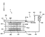
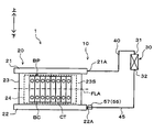
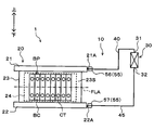
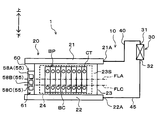
- the temperature control device 1 is applied to realize temperature control and temperature equalization of a battery pack BP as a target device, and a fluid circulation circuit 10 in which a refrigerant as a working fluid circulates, And a device control device 50.
- Arrows in FIG. 1 and the like indicate the upper side and the lower side in the gravity direction.
- the fluid circulation circuit 10 is a heat pipe that transfers heat by evaporation and condensation of the refrigerant as the working fluid, and a flow path through which a gas phase refrigerant flows and a liquid phase refrigerant It is configured as a loop-type thermosiphon separated from the flow channel.
- a fluorocarbon-based refrigerant for example, R134a, R1234yf, etc.
- the working fluid it is possible to use not only fluorocarbon-based refrigerants but also other refrigerants such as carbon dioxide, antifreeze liquid, and the like.
- the fluid circulation circuit 10 includes a device heat exchanger 20, a condenser 30, a gas phase side pipe 40, and a liquid phase side pipe 45.
- the fluid circulation circuit 10 constitutes a closed annular fluid circuit by connecting the device heat exchanger 20, the condenser 30, the gas phase side piping 40, and the liquid phase side piping 45 to one another.
- a refrigerant as a working fluid is enclosed in a state where the inside is evacuated.
- the device heat exchanger 20 is a heat exchanger that performs heat exchange between the refrigerant in the device heat exchanger 20 and the assembled battery BP when performing temperature adjustment of the assembled battery BP that is the target device.
- the device heat exchanger 20 functions as a heat absorbing portion that absorbs heat from the battery pack BP to evaporate the liquid-phase refrigerant when the battery pack BP as the target device is cooled.
- the device heat exchanger 20 has a fluid outflow portion 21, a liquid supply portion 22 and a heat exchange portion 23.
- the fluid outflow portion 21, the liquid supply portion 22, and the heat exchange portion 23 are made of, for example, a metal material having excellent thermal conductivity, such as aluminum or copper.
- the liquid supply part 22 and the heat exchange part 23 if it is a material excellent in thermal conductivity, it is also possible to use materials other than a metal.
- the fluid outlet portion 21 is formed in a cylindrical shape by a metal excellent in thermal conductivity, and is disposed on the upper side in the direction of gravity in the heat exchanger 20 for the device. At the time of cooling of the battery pack BP, the fluid outflow portion 21 is a portion where the gas phase refrigerant evaporated by heat absorption from the battery pack BP flows out of the heat exchanger 20 for the device.
- a pipe connection portion 21A is disposed at one end of the fluid outflow portion 21.
- the gas phase side piping 40 is connected to the said piping connection part 21A. That is, the pipe connection portion 21A is located on the upper side in the direction of gravity in the heat exchanger 20 for the device. Therefore, the gas-phase refrigerant in the fluid outlet 21 flows out to the gas-side piping 40 via the pipe connection 21A.
- the liquid supply portion 22 is formed in a cylindrical shape by a metal excellent in thermal conductivity, and is disposed at a position on the lower side in the direction of gravity than the fluid outflow portion 21 in the heat exchanger 20 for equipment There is.
- the liquid supply unit 22 is a portion of the refrigerant circulating in the fluid circulation circuit 10, to which the liquid-phase refrigerant is supplied to the device heat exchanger 20.
- a pipe connection portion 22A is disposed at one end of the liquid supply portion 22.
- the liquid phase side piping 45 is connected to the said piping connection part 22A. That is, the pipe connection portion 22A is located on the lower side in the direction of gravity in the heat exchanger 20 for the device. Accordingly, the liquid phase refrigerant in the fluid circulation circuit 10 is supplied from the liquid phase side pipe 45 to the heat exchanger 20 for the device via the pipe connection portion 22A of the liquid supply portion 22.
- the heat exchange part 23 of the heat exchanger 20 for apparatus is arrange
- the heat exchange section 23 is constituted by a plurality of tubes 23A aligned in the longitudinal direction of the fluid outflow section 21 and the liquid supply section 22.
- Each tube 23 ⁇ / b> A is formed in a cylindrical shape by a metal material having excellent thermal conductivity, and connects the inside of the fluid outflow portion 21 and the inside of the liquid supply portion 22. Therefore, the refrigerant, which is the working fluid, flows between the fluid outflow portion 21 and the liquid supply portion 22 while being phase-changed in each of the tubes 23A constituting the heat exchange portion 23.
- the battery pack BP is disposed outside the heat exchange unit 23 via a heat conductive sheet 24 having electrical insulation.
- the heat conduction sheet 24 ensures insulation between the heat exchange unit 23 and the battery pack BP, and suppresses the thermal resistance between the heat exchange unit 23 and the battery pack BP.
- the battery pack BP is disposed such that one side surface of each battery cell BC is in thermal contact with the battery contact surface 23S of the heat exchange unit 23.
- the battery contact surface 23S of the heat exchange unit 23 is configured by arranging a plurality of tubes 23A.
- each battery cell BC opposite to the surface on which the terminal CT is provided is arranged to be in contact with the battery contact surface 23S via the heat conductive sheet 24.
- Each battery cell BC which comprises the assembled battery BP is arranged in the direction which cross
- FIG. 1 one surface side of the heat exchange unit 23 is illustrated, but the battery cells BC are also arranged on the back surface side, and the battery contact surface corresponding to the back surface side via the heat conduction sheet 24 Contact to 23S.
- the condenser 30 is a heat exchanger that functions as a heat dissipation unit that causes the gas phase refrigerant evaporated inside the device heat exchanger 20 to dissipate when the battery pack BP, which is the target device, is cooled.
- the condenser 30 according to the first embodiment is constituted by a refrigerant-refrigerant condenser, and heat exchange is performed between the gas-phase refrigerant flowing in the fluid circulation circuit 10 and the low-pressure refrigerant flowing in the refrigeration cycle apparatus (not shown). The heat of the phase refrigerant is dissipated to the low pressure refrigerant.
- the refrigeration cycle apparatus has a vapor compression refrigeration cycle, and is used to air-condition the interior of a vehicle.
- the refrigeration cycle apparatus includes a compressor, a refrigerant condenser, a pressure reducing unit (for example, an expansion valve), and an evaporator.
- the condenser 30 is made of, for example, a metal or an alloy having excellent thermal conductivity, such as aluminum or copper.
- a material other than metal as long as the material is excellent in thermal conductivity.
- at least a portion of the condenser 30 which exchanges heat with air is desirably made of a material having excellent thermal conductivity.
- An inlet 31 is disposed on the upper side of the condenser 30 in the direction of gravity.
- the upper end of the gas phase side pipe 40 in the direction of gravity is connected to the inlet 31. Therefore, in the inflow port 31, the gas phase refrigerant flowing through the gas phase side pipe 40 flows into the inside of the condenser 30.
- the outflow port 32 is disposed on the lower side of the condenser 30 in the direction of gravity.
- the upper end of the liquid phase side pipe 45 in the direction of gravity is connected to the outlet 32. Therefore, in the outlet 32, the liquid-phase refrigerant condensed by heat exchange with the low-pressure refrigerant flowing in the refrigeration cycle device inside the condenser 30 flows out to the liquid-phase side pipe 45.
- the liquid phase refrigerant has a correlation between the low pressure refrigerant and the temperature.
- the condenser 30 is disposed at a position overlapping the heat exchange portion 23 of the heat exchanger 20 for the device in the direction orthogonal to the direction of gravity. However, the condenser 30 is configured such that at least the position of the inflow port 31 is higher than the liquid level of the refrigerant inside the condenser 30 so that the refrigerant can be condensed inside.
- the gas phase side pipe 40 is a refrigerant flow path which leads the gas phase refrigerant evaporated in the device heat exchanger 20 to the condenser 30.
- the gas phase side piping 40 corresponds to a gas phase flow path portion. As shown in FIG. 1, one end of the gas phase side pipe 40 is connected to the pipe connection portion 21A of the heat exchanger 20 for the apparatus, and the other end of the gas phase side pipe 40 is a flow of the condenser 30. It is connected to the inlet 31.
- the liquid phase side pipe 45 is a refrigerant flow path for guiding the liquid phase refrigerant condensed by the condenser 30 to the heat exchanger 20 for the device.
- the liquid phase side pipe 45 corresponds to a liquid phase flow channel portion.
- one end of the liquid phase side pipe 45 is connected to the pipe connection portion 22A of the heat exchanger 20 for the apparatus, and the other end portion of the liquid phase side pipe 45 is a flow of the condenser 30 It is connected to the outlet 32.
- the piping route of the gas phase side piping 40 and the liquid phase side piping 45 shown in FIG. 1 is an example, and can be appropriately changed in consideration of the mountability to a vehicle.
- the liquid refrigerant starts to evaporate in the heat exchanger 20 for the device.
- the battery assembly BP in thermal contact with the heat exchanger 20 is cooled by the latent heat of vaporization of the liquid-phase refrigerant in the heat exchanger 20 for equipment.
- the refrigerant inside the device heat exchanger 20 is phase-changed by evaporation and the density is reduced.
- the gas phase refrigerant evaporated in the device heat exchanger 20 moves upward inside the device heat exchanger 20 due to the density difference, and flows into the condenser 30 through the gas side piping 40.
- the gas phase refrigerant flowing into the condenser 30 is liquefied by radiating heat to the low pressure refrigerant of the refrigeration cycle apparatus in the condenser 30.
- the liquid-phase refrigerant condensed in the condenser 30 flows into the heat exchanger 20 for equipment again through the liquid-side piping 45 by the action of gravity.
- the temperature adjustment device 1 can realize continuous cooling of the battery pack BP by natural circulation of the refrigerant without requiring a driving device such as a compressor.
- the temperature adjusting device 1 naturally circulates the refrigerant as the working fluid in the fluid circulation circuit 10 by changing the phase of the working fluid, and adjusts the temperature of the battery pack BP as the target device.
- the device heat exchanger 20 in order to realize appropriate heat exchange with the battery pack BP, it is desirable that an appropriate amount of refrigerant be enclosed in the fluid circulation circuit 10.
- an appropriate amount of the refrigerant for example, when the temperature adjustment device 1 is stopped, the amount of refrigerant in which the liquid surface position of the liquid phase refrigerant is located at a height which is 1/2 of the height of the heat exchange portion 23 it can.
- the amount of refrigerant enclosed means the amount of refrigerant enclosed in the fluid circulation circuit 10, and corresponds to the amount of fluid enclosed.
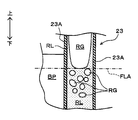
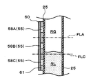
- FIG. 2 shows the inside of the heat exchange unit 23 when a proper amount of refrigerant is sealed in the fluid circulation circuit 10 when the battery pack BP is cooled.
- the appropriate liquid surface position FLA indicates the position of the liquid surface of the liquid-phase refrigerant in the heat exchanger 20 for the device, when the amount of refrigerant sealed in the fluid circulation circuit 10 is appropriate.
- the heat exchange unit 23 of the device heat exchanger 20 is configured of a plurality of tubes 23A. Therefore, the side surface of the battery cell BC which comprises the assembled battery BP is in thermal contact with the outer surface of each tube 23A.
- each tube 23A constitutes a part of the fluid circulation circuit 10
- the inside of the tube 23A constitutes a flow path of a refrigerant which is a working fluid.
- the liquid phase refrigerant RL is present on the lower side in the direction of gravity in the tube 23A, and the gas phase refrigerant RG is present on the upper side.
- the heat generated in the battery cell BC is transferred to the refrigerant inside the tube 23A through the tube 23A constituting the heat exchange portion 23. .
- the liquid phase refrigerant RL boils and changes in phase to a gas phase refrigerant RG.
- the battery cells BC constituting the battery pack BP are cooled by the latent heat of vaporization of the liquid phase refrigerant RL at this time.
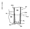
- the liquid phase refrigerant RL boils and changes its phase to a gas phase refrigerant RG.
- bubbles of the gas phase refrigerant RG generated by the boiling are repelled on the liquid surface of the liquid phase refrigerant RL.
- the liquid level of the liquid-phase refrigerant RL is located below the appropriate liquid level FLA. For this reason, unlike the case shown in FIG. 2, a portion not wetted by the liquid phase refrigerant RL is generated on the upper side in the direction of gravity of the inner wall surface of each tube 23A.
- each tube 23A which is not wetted by the liquid-phase refrigerant RL is heated by the heat of the battery pack BP to raise its temperature. Further, a portion of the tube 23A not wetted by the liquid phase refrigerant RL is in contact with the gas phase refrigerant RG. Therefore, the gas phase refrigerant RG is also heated by the influence of the heat of the battery pack BP, and the temperature thereof is increased.
- the battery assembly BP is generated by the latent heat of evaporation of the liquid phase refrigerant RL as in the case of the appropriate liquid level FLA. Cooling is performed.
- the cooling performance of the assembled battery BP differs at the upper and lower sides in the direction of gravity.
- the temperature distribution of the battery surface temperature of the battery pack BP is biased in the vertical direction in the direction of gravity.
- the battery internal temperature of the battery pack BP is also biased upward and downward in the direction of gravity.
- the appropriate liquid level position FLA can be defined as the liquid level position of the liquid-phase refrigerant RL that can wet the entire inner wall surface of the heat exchange unit 23 in the apparatus heat exchanger 20 with the liquid-phase refrigerant RL.
- the amount of refrigerant charged into the fluid circulation circuit 10 at that time can be defined as the appropriate amount sealed.
- the appropriate enclosed amount is an example of a reference amount.
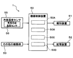
- the device control device 50 is configured of a known microcomputer including a CPU, a ROM, a RAM, and the like, and peripheral circuits thereof.
- the device control device 50 performs various operations and processing based on the control program stored in the ROM.
- a refrigerant temperature sensor 55 is connected to the input side of the device control device 50.
- the refrigerant temperature sensor 55 detects a physical quantity that has a correlation with the temperature of the refrigerant that is the working fluid sealed in the fluid circulation circuit 10.
- the refrigerant temperature sensor 55 corresponds to a physical quantity detection unit.
- a gas phase refrigerant temperature sensor 56 is connected as the refrigerant temperature sensor 55. That is, the refrigerant temperature sensor 55 includes the gas phase refrigerant temperature sensor 56.
- the gas-phase refrigerant temperature sensor 56 detects a physical quantity that has a correlation with the temperature of the gas-phase refrigerant inside the fluid circulation circuit 10 as a gas-phase physical quantity. That is, the gas phase refrigerant temperature sensor 56 corresponds to a gas phase physical quantity detection unit.
- the gas-phase refrigerant temperature sensor 56 As shown in FIG. 1, the gas-phase refrigerant temperature sensor 56 according to the first embodiment is disposed on the surface of the heat exchange unit 23 in the device heat exchanger 20.
- the gas phase refrigerant temperature sensor 56 is disposed on the heat exchange section 23 above the appropriate liquid surface position FLA in the direction of gravity.
- the gas phase refrigerant temperature sensor 56 is arranged as described above because the evaporated gas phase refrigerant flows above the appropriate liquid surface position FLA in the heat exchange unit 23. By doing this, the surface temperature of the heat exchanger 23 can be detected as a physical quantity that has a correlation with the temperature of the gas phase refrigerant.
- the gas phase refrigerant temperature sensor 56 is disposed at a position close to the upper end of the battery pack BP which is the target device in the heat exchange unit 23. By arranging in this manner, it is possible to ensure a long heating period of the gas phase refrigerant flowing upward inside the heat exchange unit 23 by the heat of the battery pack BP until the detection by the gas phase refrigerant temperature sensor 56. That is, the gas phase refrigerant temperature sensor 56 can detect a large temperature change of the gas phase refrigerant.
- the gas phase refrigerant temperature sensor 56 estimates or calculates the temperature of the gas phase refrigerant in the inside from the surface temperature of the heat exchange unit 23 detected by the gas phase refrigerant temperature sensor 56, and calculates this as a gas phase physical quantity It may be configured to output as. Further, when disposing the gas phase refrigerant temperature sensor 56 with respect to the heat exchange portion 23, it is desirable to select a position which has little influence on the heat exchange between the refrigerant inside the heat exchange portion 23 and the assembled battery BP.
- a notification device 51 and a storage device 52 are connected to the output side of the device control device 50.
- the notification device 51 includes, for example, an audio output unit for outputting information in voice and an information display unit for visually displaying information.
- the notification device 51 can notify the user of the fact that the amount of refrigerant enclosed in the fluid circulation circuit 10 is smaller than the amount appropriately enclosed according to a control program described later.
- the notification device 51 corresponds to a notification unit.
- the storage device 52 is configured to be able to rewrite the stored content, and, for example, when the amount of filled refrigerant is smaller than the appropriate amount of enclosed, etc., history information indicating that is written.
- the other device group 53 is connected to the device control device 50.
- the other device group 53 includes a battery control device for controlling the battery pack BP and an air conditioning control device for controlling the operation of the refrigeration cycle device.
- the battery control device is connected to a current sensor that detects an output current value of the assembled battery BP, a battery temperature sensor that detects a battery temperature that is an internal temperature of the assembled battery BP, and the like. Therefore, the device control device 50 can perform input / output control of the assembled battery BP and obtain the output current value and the battery temperature of the assembled battery BP via the battery control device which is the other device group 53. .
- the constituent elements (for example, a compressor and a pressure reducing unit) in the refrigeration cycle apparatus are connected to the air conditioning control device. Further, an air conditioning sensor group is connected to the air conditioning control device.
- the air conditioning sensor group includes an outside air temperature sensor for detecting the outside air temperature Tam.
- the device control device 50 performs operation control of various components of the refrigeration cycle device and acquisition of detection values by the air conditioning sensor group via the air conditioning control device which is the other device group 53. it can.
- a control unit for controlling various control target devices connected to the output side is integrally configured, but a configuration for controlling the operation of each control target device (hardware and software ) Constitute a control unit that controls the operation of each control target device.
- the configuration for specifying the battery heat generation amount Q of the battery pack BP from various detection values is the heat generation amount specifying unit 50A.
- the heat generation amount specifying unit 50A corresponds to a heat generation amount detection unit.
- the configuration for setting the reference value for determining the decrease in the refrigerant charge amount from various detection values is the reference value setting unit 50B.
- the reference value setting unit 50B corresponds to a reference physical quantity setting unit.
- the configuration for estimating the amount of refrigerant enclosed in the fluid circulation circuit 10 is a fluid amount estimation unit 50C.
- the fluid volume estimation unit 50C corresponds to a fluid volume estimation unit.
- the configuration to determine whether the refrigerant charge amount is smaller than a predetermined amount is the decrease determination unit 50D.
- the decrease determination unit 50D corresponds to a decrease determination unit.
- the operation of the temperature control device 1 when cooling the battery pack BP will be described in detail.
- the liquid in the heat exchange unit 23 Part of the phase refrigerant evaporates due to the heat from the battery pack BP.
- the battery pack BP is cooled by the evaporation latent heat of the liquid-phase refrigerant in the heat exchanger 20 for equipment, and the temperature of the battery pack BP is lowered.
- the refrigerant changes its phase from the liquid phase to the gas phase, so its specific gravity decreases. Therefore, the gas phase refrigerant evaporated in the device heat exchanger 20 moves upward in the heat exchange unit 23 and flows out to the gas phase side piping 40 from the pipe connection portion 21A of the fluid outflow portion 21. The gas phase refrigerant flows into the condenser 30 via the gas phase side pipe 40.
- the heat of the gas phase refrigerant is dissipated to another heat medium (in the first embodiment, the low pressure refrigerant in the refrigeration cycle apparatus).
- the gas phase refrigerant is condensed in the inside of the condenser 30, and becomes a liquid phase refrigerant. Since the specific gravity of the refrigerant increases due to this phase change, the liquid-phase refrigerant condensed inside the condenser 30 flows downward from the outlet 32 of the condenser 30 in the direction of gravity by its own weight.
- the liquid-phase refrigerant flowing out of the condenser 30 moves to the pipe connection portion 22A of the liquid supply portion 22 in the heat exchanger 20 for the device via the liquid-phase side pipe 45.
- the said liquid phase refrigerant flows in into the inside of the heat exchanger 20 for apparatuses from piping connection part 22A.
- the temperature of the battery pack BP is higher than the boiling point of the refrigerant, the liquid phase refrigerant in the device heat exchanger 20 is evaporated by the heat from the battery pack BP.
- the refrigerant is circulated between the heat exchanger 20 for the device and the condenser 30 while being phase-changed into the gas phase state and the liquid phase state. Heat can be transported to the condenser 30. Then, in the condenser 30, the heat of the transported refrigerant can be dissipated to the other heat medium.
- the temperature adjustment device 1 can dissipate the heat of the battery pack BP absorbed by the device heat exchanger 20 to another heat medium in the condenser 30 via the refrigerant that is the working fluid,
- the battery pack BP can be cooled.
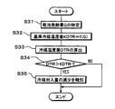
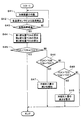
- a control process performed by the device control device 50 when the battery pack BP is cooled will be described with reference to FIG.
- the control process shown in the flowchart of FIG. 5 is realized by reading out the control program stored in the ROM of the device control device 50 and executing the control program by the device control device 50.
- Each step of the control processing constitutes a function realizing unit for realizing various functions executed by the temperature adjustment device 1.
- step S ⁇ b> 1 the initial surface temperature TS ⁇ b> 0 at the start of operation of the temperature adjustment device 1 is detected by the gas phase refrigerant temperature sensor 56 which is one of the refrigerant temperature sensors 55.
- the gas-phase refrigerant temperature sensor 56 is disposed on the upper surface of the heat exchange unit 23 in the device heat exchanger 20, and as described with reference to FIGS. Of the portion 23, the portion where the gas phase refrigerant is likely to be present. Accordingly, the initial surface temperature TSO corresponds to a physical quantity that has a correlation with the temperature of the gas-phase refrigerant at the initial stage of operation of the temperature adjustment device 1.
- a battery heat generation amount Q which is a heat generation amount of the battery pack BP, is specified.
- the battery heating value Q is calculated using the output current value of the assembled battery BP acquired via the battery control device which is the other device group 53, and the electrical resistance value inside the assembled battery BP.
- the device control device 50 that executes step S2 functions as a heat generation amount specification unit 50A, and corresponds to the heat generation amount specification unit.
- various methods can be employed as a method of specifying the battery heating value Q.
- a configuration may be employed in which the power is estimated from at least one state of the battery pack BP, such as the electric energy, the current value, the battery temperature, the environmental temperature, the heat quantity, and the heat capacity.
- the battery control device is configured to be capable of detecting the battery heat generation amount Q
- a configuration may be adopted in which the battery heat generation amount Q is acquired via the battery control device.
- reference surface temperature KTS is set using battery heating value Q and initial surface temperature TS0.
- the reference surface temperature KTS is used as an evaluation criterion for evaluating the amount of refrigerant enclosed in the fluid circulation circuit 10, and corresponds to a reference physical amount.
- the temperature control device 1 when a battery calorific value Q is generated in the battery pack BP which is the target device, the temperature of the battery pack BP does not rise and the input / output characteristics do not deteriorate.
- the target temperature is predetermined.
- the temperature of the liquid-phase refrigerant in the condenser 30 is adjusted. Since the liquid phase refrigerant whose temperature has been adjusted is supplied from the condenser 30 to the device heat exchanger 20, the temperature of the battery pack BP is adjusted by heat exchange with the liquid phase refrigerant in the device heat exchanger 20. There is.
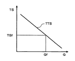
- the target surface temperature TTS is set to be smaller as the battery heat generation amount Q is larger.
- the value of the target surface temperature TTS on the upper side of the heat exchange unit 23 is specified as TSf.
- the heat radiation performance of the condenser 30 is adjusted so that the surface temperature TS on the upper side of the heat exchange unit 23 becomes the target surface temperature TTS, and the liquid phase refrigerant flowing out of the condenser 30 Temperature is also adjusted.
- a temperature change LA indicated by a solid line indicates a temperature change when the appropriate amount of the refrigerant is enclosed in the fluid circulation circuit 10, and the liquid level of the liquid-phase refrigerant in the device heat exchanger 20 is the appropriate liquid This means the temperature change in the state at the plane position FLA.
- a temperature change LC indicated by a broken line in FIG. 7 indicates a temperature change when the warning enclosed amount of refrigerant is enclosed in the fluid circulation circuit 10, and the liquid surface of the liquid-phase refrigerant in the heat exchanger 20 for equipment Means the temperature change in the state where it is in the warning liquid level FLC described later.
- the warning charge amount is a refrigerant charge amount less than the proper charge amount, and corresponds to, for example, the lower limit value of the refrigerant charge amount allowed from the viewpoint of performance maintenance and temperature uniformity of the assembled battery BP.
- the said warning enclosed quantity is an example of a reference quantity, and is equivalent to a warning reference quantity.
- the warning liquid level position FLC indicates the liquid level position of the liquid-phase refrigerant in the heat exchanger 20 for the device when the refrigerant of the warning sealing amount is sealed in the fluid circulation circuit 10.
- the temperature change of the surface temperature TS when heat is generated so that the battery calorific value Q of the assembled battery BP becomes Qf from the state of the initial surface temperature TS0 as in the above-described exemplification will be described as a specific example. As indicated by the solid line in FIG. 7, when the proper amount of the refrigerant is enclosed, the surface temperature TS becomes higher as time passes from time t0 indicating the start of heat generation of the battery pack BP.
- the surface temperature TS reaches TSf which is the above-described target surface temperature TTS.
- the surface temperature TS indicates TSn at time tn when determining the amount of refrigerant charged in the fluid circulation circuit 10.
- the surface temperature TS is a time indicating the start of heat generation of the battery pack BP, as shown by a broken line in FIG. It becomes high as time passes from t0. At this time, as time passes, the surface temperature TS shows a temperature higher than the surface temperature when the appropriate amount of encapsulation is enclosed.
- the surface temperature TS (i.e., TSn) at time tn when the appropriate enclosed amount is enclosed is defined as the reference surface temperature KTS.
- the surface temperature at time tn when the amount of the enclosed alert is enclosed is used as a reference and compared with the surface temperature TS detected by the gas phase refrigerant temperature sensor 56, it is enclosed in the fluid circulation circuit 10 at this time It can be determined whether the refrigerant charge amount is decreasing with reference to the warning charge amount.
- the reference surface temperature KTS when the appropriate amount of encapsulation is enclosed, and the reference surface temperature KTS when the amount of enclosed alert is enclosed are specified with the initial surface temperature TS0 and the battery heat generation amount Q as parameters. can do.
- a control map in which the reference surface temperature KTS, the initial surface temperature TS0, and the battery heating value Q are associated with each other is created in advance by measurement or calculation.
- the control map is stored in the ROM of the device control device 50.
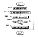
- step S3 the control map stored in the ROM of the device control apparatus 50 is read, and using the initial surface temperature TS0 detected in step S1 and the battery heat generation amount Q specified in step S2, the reference surface temperature KTS Is identified.
- the device control apparatus 50 that executes step S3 functions as a reference value setting unit 50B, and corresponds to a reference physical quantity setting unit.
- the gas temperature refrigerant temperature sensor 56 detects the surface temperature TS on the upper side of the heat exchanger 23 at the present time.
- step S5 it is determined whether or not the current surface temperature TS is higher than the reference surface temperature KTS relating to the appropriate enclosed amount. If the current surface temperature TS is higher than the reference surface temperature KTS, the current amount of refrigerant enclosed is smaller than the appropriate amount enclosed, and the liquid level position of the liquid phase refrigerant in the device heat exchanger 20 is higher than the appropriate liquid level position FLA It can be estimated that it is located below.
- the refrigerant charge amount at the present time is equal to or larger than the appropriate charge amount, and the liquid level position of the liquid phase refrigerant in the heat exchanger 20 for equipment is the appropriate liquid It can be estimated that it is located at the same level as the surface position FLA or above the appropriate liquid surface position FLA. Thereafter, this control process is ended.
- the device control device 50 in the case of executing step S5 functions as the fluid amount estimating unit 50C, and corresponds to the fluid amount estimating unit.
- the device control apparatus 50 in the case of executing step S5 functions as the decrease determination unit 50D because it determines whether the amount of the current refrigerant and the appropriate amount are smaller than the appropriate amount. It corresponds to the determination unit.
- step S5 it can be determined in step S5 whether the current refrigerant enclosed amount is smaller than the warning enclosed amount. That is, it is also possible to determine whether the liquid level position of the liquid phase refrigerant in the heat exchanger 20 for equipment is located below the warning liquid level position FLC.
- step S6 a notification signal indicating that the refrigerant charge amount at the present time is smaller than the appropriate charge amount is output to the notification device 51.
- the notification device 51 notifies the user that the current amount of filled refrigerant is smaller than the appropriate amount of filling, by means of the voice output unit and the information display unit.
- step S5 If it is determined in step S5 that the amount of refrigerant charged at present is smaller than the amount of alarm charge, a warning signal indicating that is output to the notification device 51.
- the notification device 51 controls the operation of the voice output unit and the information display unit based on the warning signal, and warns that the current amount of filled refrigerant is smaller than the amount of filled warning.
- the warning in the notification device 51 be in a mode in which appealing power is higher than the notification based on the notification signal.
- the volume may be made larger than that at the time of notification.
- the display period may be made longer or the display size may be larger than at the time of notification.
- the fluid circulation circuit has a simple configuration in which the refrigerant temperature sensor 55 detects the temperature of the refrigerant that undergoes a phase change inside the fluid circulation circuit 10. The amount of refrigerant enclosed in 10 can be estimated.
- the temperature adjustment device 1 Since the control of the amount of injected refrigerant in the fluid circulation circuit 10 can be performed by estimating the amount of injected refrigerant, the temperature adjustment device 1 is used to maintain or equalize the temperature adjustment performance of the battery pack as the target device. Can contribute.
- a gas phase refrigerant temperature sensor 56 is disposed as the refrigerant temperature sensor 55, and a surface temperature TS having a correlation with the temperature of the gas phase refrigerant is detected.
- the said temperature adjustment apparatus 1 estimates the refrigerant
- the surface temperature can be detected as a physical quantity that has a correlation with the temperature of the gas-phase refrigerant with respect to the refrigerant that undergoes phase change inside the fluid circulation circuit 10, and the refrigerant filling amount serving as a reference Can be used to accurately estimate the amount of refrigerant currently charged.
- the gas phase refrigerant temperature sensor 56 is disposed above the appropriate liquid level FLA in the heat exchange section 23 of the device heat exchanger 20 in the direction of gravity. As described with reference to FIG. 2 and FIG. 3 and the like, the evaporated gas phase refrigerant flows above the appropriate liquid surface position FLA in the device heat exchanger 20. Therefore, the gas phase refrigerant temperature sensor 56 can reliably detect the surface temperature TS having a correlation with the temperature of the gas phase refrigerant.
- the battery heat generation amount Q of the battery pack BP is specified in step S2, and in step S3, the reference surface temperature KTS is set according to the battery heat generation amount Q. That is, since the temperature adjustment device 1 can change the reference for estimating the refrigerant charge amount according to the operation state of the battery pack BP, it is possible to accurately estimate the refrigerant charge amount at the present time.
- step S5 in order to determine whether or not the amount of refrigerant enclosed in the fluid circulation circuit 10 is reduced in step S5, maintenance and temperature equalization of the temperature adjustment performance for the battery pack BP Can contribute to
- step S5 when it is determined in step S5 that the refrigerant charging amount at the present time is smaller than the reference refrigerant charging amount (that is, the proper charging amount and the warning charging amount), the temperature adjustment device 1 notifies The device 51 can notify the user to that effect.
- the reference refrigerant charging amount that is, the proper charging amount and the warning charging amount
- the user can appropriately take measures (for example, for the fluid circulation circuit 10) based on the notification content of the notification device 51 with respect to the management of the amount of refrigerant enclosed in the fluid circulation circuit 10. It is possible to take care of the replenishment of the refrigerant. As a result, the temperature control device 1 can reliably contribute to the maintenance and temperature equalization of the temperature control performance for the battery pack as the target device.
- FIG. 8 the same or equivalent parts as in the first embodiment are denoted by the same reference numerals. The same applies to the following drawings.
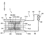
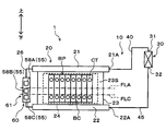
- thermosiphon-type temperature adjustment device 1 adjusts the temperature of the assembled battery BP, with the assembled battery BP mounted on a vehicle such as an electric vehicle as a target device. It is applied as a device.
- the temperature adjustment device 1 includes the fluid circulation circuit 10 and the device control device 50 as in the first embodiment.
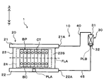
- the fluid circulation circuit 10 is configured to include an apparatus heat exchanger 20, a condenser 30, a gas phase side pipe 40, and a liquid phase side pipe 45.
- the arrangement position of the gas phase refrigerant temperature sensor 56 constituting the refrigerant temperature sensor 55 is different from that in the first embodiment.
- the other configuration is the same as that of the first embodiment, and thus the description thereof is omitted.
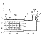
- the gas phase refrigerant temperature sensor 56 is disposed in the gas phase side pipe 40 instead of the heat exchange unit 23 of the device heat exchanger 20.
- the gas phase refrigerant temperature sensor 56 is disposed in a portion of the gas phase side piping 40 near the heat exchanger 20 for the device.
- the gas phase refrigerant temperature sensor 56 is disposed at a portion of the gas phase side piping 40 closer to the pipe connection portion 21A of the heat exchanger 20 for the device than the inlet 31 of the condenser 30 It is located on the upper side in the direction of gravity than the appropriate liquid surface position FLA.
- the gas phase refrigerant temperature sensor 56 can directly detect the temperature of the gas phase refrigerant flowing out from the pipe connection portion 21A of the fluid outflow portion 21 in the heat exchanger 20 for an apparatus. Further, the gas phase refrigerant temperature sensor 56 is connected to the input side of the device control device 50 as the refrigerant temperature sensor 55 as in the first embodiment.
- the gas phase refrigerant temperature sensor 56 according to the second embodiment corresponds to a gas phase physical quantity detection unit.
- the temperature adjustment device 1 realizes continuous cooling of the battery pack BP by natural circulation of the refrigerant without requiring a driving device such as a compressor. it can.
- the liquid surface position of the liquid phase refrigerant RL in the heat exchanger 20 for equipment is at the appropriate liquid surface position FLA, as described with reference to FIG.
- the RL wets the entire inner wall surface of the tube 23A in the vertical direction.
- the battery assembly BP can be cooled by the latent heat of vaporization of the liquid-phase refrigerant in the entire area of the heat exchange section 23 of the heat exchanger 20 for equipment.
- the refrigerant in the heat exchanger 23 causes a phase change from the liquid phase to the gas phase due to latent heat, the temperatures of the liquid phase refrigerant and the gas phase refrigerant show similar values.
- the vapor-phase refrigerant evaporated below the heat exchange unit 23 moves upward in each tube 23A due to the difference in specific gravity, and passes through a portion not wetted by the liquid-phase refrigerant RL.
- the gas phase refrigerant is heated by the heat generated in the assembled battery BP, and its temperature rises, so it becomes superheated (superheat).
- the heat generated in the battery pack BP lengthens the period during which the gas phase refrigerant is heated, and the degree of superheat of the gas phase refrigerant increases.
- the temperature control device 1 detects the temperature of the gas phase refrigerant circulating in the fluid circulation circuit 10 by the gas phase refrigerant temperature sensor 56 disposed in the gas phase side pipe 40, thereby the heat exchanger 20 for the device. It is possible to estimate the liquid level position of the liquid-phase refrigerant in the inside and the amount of refrigerant enclosed in the fluid circulation circuit 10.
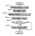
- control processing executed by the device control device 50 when cooling the battery pack BP will be described with reference to FIG.
- the control process shown in the flowchart of FIG. 9 is realized by reading out the control program stored in the ROM of the device control device 50 and executing the control program by the device control device 50.
- step S11 the initial gas phase refrigerant temperature TG0 at the start of operation of the temperature adjustment device 1 is detected by the gas phase refrigerant temperature sensor 56 which is one of the refrigerant temperature sensors 55.
- the temperature of the gas-phase refrigerant that has flowed out from the pipe connection portion 21A of the heat exchanger 20 for an apparatus to the gas-phase side pipe 40 is detected.
- step S12 as in step S2 of the first embodiment, the battery heating value Q of the battery pack BP is specified.
- the reference gas phase refrigerant temperature KTG is set using the battery heating value Q and the initial gas phase refrigerant temperature TG0.
- the reference gas phase refrigerant temperature KTG is used as an evaluation standard for evaluating the amount of refrigerant enclosed in the fluid circulation circuit 10, and corresponds to a reference physical quantity.
- the relationship between the battery heat generation amount Q, the initial gas phase refrigerant temperature TG0, and the reference gas phase refrigerant temperature KTG will be described.
- the relationship between the battery heating value Q of the assembled battery BP and the target value of the gas phase refrigerant temperature TG will be described.
- the target value of the gas phase refrigerant temperature TG is determined in accordance with the battery heating value Q.
- the target value of the gas phase refrigerant temperature TG is set to be smaller as the battery heat generation amount Q of the assembled battery BP is larger.
- the time change of the gas phase refrigerant temperature TG due to the heat generation of the assembled battery BP will be described. As described above, as the amount of the refrigerant sealed in the fluid circulation circuit 10 decreases and the liquid level position of the liquid phase refrigerant in the heat exchange unit 23 decreases, the heat generated in the battery pack BP heats the gas phase refrigerant Period will be longer.
- the gas phase refrigerant temperature TG when the liquid level in the device heat exchanger 20 is at the warning liquid level FLC is at the appropriate liquid level FLA. It is higher than the gas phase refrigerant temperature TG in one case.
- the gas phase refrigerant temperature TG at time tn can be set to the reference gas phase refrigerant temperature KTG.
- the reference gas phase refrigerant temperature KTG in the case where the appropriate enclosed amount is enclosed, and the reference gas phase refrigerant temperature KTG in the case where the alert enclosed amount is enclosed are the initial gas phase refrigerant temperature TG0 and the battery calorific value Q. Can be specified as a parameter.
- a control map in which the reference gas phase refrigerant temperature KTG, the initial gas phase refrigerant temperature TG0, and the battery heat generation amount Q are associated is created in advance by measurement or calculation. There is.
- the control map is stored in the ROM of the device control device 50.
- step S13 the control map stored in the ROM of the device control apparatus 50 is read out, and using the initial gas phase refrigerant temperature TG0 detected in step S11 and the battery heating value Q specified in step S12, the reference air The phase refrigerant temperature KTG is identified.
- the device control apparatus 50 that executes step S13 functions as a reference value setting unit 50B and corresponds to a reference physical quantity setting unit.
- the gas phase refrigerant temperature sensor 56 detects the gas phase refrigerant temperature TG of the gas phase refrigerant flowing out to the gas phase side pipe 40 at the present time.
- step S15 it is determined whether or not the gas phase refrigerant temperature TG at the present time is higher than the reference gas phase refrigerant temperature KTG relating to the appropriate enclosed amount.
- the refrigerant charge amount at the present time is smaller than the appropriate charge amount, and the liquid level position of the liquid phase refrigerant in the heat exchanger 20 for equipment is the appropriate liquid level It can be estimated that it is located below position FLA.
- the amount of refrigerant charged at the present time is equal to or larger than the amount appropriately sealed, and the liquid level position of the liquid-phase refrigerant in the heat exchanger 20 for equipment is the same as or appropriate position above the liquid level FLA. It can be estimated that Thereafter, this control process is ended.
- the device control apparatus 50 in the case of executing step S15 functions as a fluid volume estimation unit 50C and a reduction determination unit 50D as in the first embodiment, and corresponds to a fluid volume estimation unit and a reduction determination unit.
- step S16 a control signal (that is, a notification signal or a warning signal) according to the determination result of step S15 is output to the notification device 51.
- the notification device 51 notifies the user that the current amount of filled refrigerant is smaller than the appropriate amount of enclosed charge or the amount of filled in alert, by the voice output unit and the information display unit.
- this control process is ended.
- the same advantages as those of the first embodiment can be obtained from the same configuration and operation as those of the first embodiment.
- the gas phase refrigerant temperature sensor 56 is disposed in the gas phase side piping 40 at a portion near the pipe connection portion 21A of the heat exchanger 20 for equipment .
- the gas phase side pipe 40 corresponds to a portion with good workability, the workability relating to the arrangement operation and maintenance of the gas phase refrigerant temperature sensor 56 with respect to the gas phase side pipe 40 can be improved.
- the arrangement of the gas phase refrigerant temperature sensor 56 in the temperature control device 1 according to the first embodiment and the second embodiment described above can detect a physical quantity having a correlation with the temperature of the gas phase refrigerant in the fluid circulation circuit 10 And can be changed as appropriate.
- the gas phase refrigerant temperature sensor 56 as the refrigerant temperature sensor 55 can also be arranged at the arrangement position PGA or the arrangement position PGB shown in FIG.
- the arrangement position PGA indicates the fluid outlet 21 located above the heat exchanger 20 for the device.
- the gas phase refrigerant evaporated in the heat exchange unit 23 flows upward through the tubes 23 A of the heat exchange unit 23 and merges in the fluid outflow unit 21. Therefore, if the gas phase refrigerant temperature sensor 56 is arranged at the arrangement position PGA, it is possible to reliably detect the physical quantity having a correlation with the temperature of the gas phase refrigerant.
- the arrangement position PGB indicates the periphery of the inlet 31 in the condenser 30.
- the gas phase refrigerant flowing through the gas phase side pipe 40 flows into the inside of the condenser 30. Therefore, if the gas phase refrigerant temperature sensor 56 is arranged at the arrangement position PGB, it is possible to reliably detect the physical quantity having a correlation with the temperature of the gas phase refrigerant.
- the gas phase refrigerant temperature sensor 56 may be disposed at a plurality of locations in the fluid circulation circuit 10. For example, combining the first embodiment and the second embodiment described above, both the estimation of the refrigerant charge amount by the surface temperature TS and the estimation of the refrigerant charge amount by the gas phase refrigerant temperature TG in the gas phase side pipe 40 are performed It is also possible to configure it to
- thermosyphon type temperature control device 1 uses the battery pack BP mounted on a vehicle such as an electric vehicle as a target device and adjusts the temperature of the battery pack BP, as in the above-described embodiments. Applied as a device to
- the temperature adjustment device 1 includes the fluid circulation circuit 10 and the device control device 50, as in the above-described embodiments.
- the fluid circulation circuit 10 is configured to include an apparatus heat exchanger 20, a condenser 30, a gas phase side pipe 40, and a liquid phase side pipe 45.
- a liquid-phase refrigerant temperature sensor 57 is disposed as the refrigerant temperature sensor 55 instead of the gas-phase refrigerant temperature sensor 56.
- the other configuration is the same as that of the embodiment described above, and thus the description thereof is omitted.
- the liquid-phase refrigerant temperature sensor 57 As shown in FIG. 11, the liquid-phase refrigerant temperature sensor 57 according to the third embodiment is disposed on the surface of the heat exchange unit 23 in the heat exchanger 20 for the device.
- the liquid phase refrigerant temperature sensor 57 detects the surface temperature TS as a physical quantity that has a correlation with the temperature of the liquid phase refrigerant.
- the liquid phase refrigerant temperature sensor 57 is connected to the input side of the device control device 50 as the refrigerant temperature sensor 55. Therefore, the liquid phase refrigerant temperature sensor 57 corresponds to a liquid phase physical quantity detection unit. And in the heat exchange part 23, the liquid phase refrigerant temperature sensor 57 which concerns on 3rd Embodiment is arrange
- the liquid-phase refrigerant is located below the appropriate liquid surface position FLA in the heat exchange unit 23. Therefore, by disposing the liquid phase refrigerant temperature sensor 57 in this manner, the temperature of the liquid phase refrigerant can be detected via the surface temperature of the heat exchange unit 23.
- the liquid-phase refrigerant temperature sensor 57 is disposed below the appropriate liquid level FLA in the heat exchange unit 23 and as close as possible to the appropriate liquid level FLA.
- This position is a position that appears early as a temperature change of the surface temperature TS when the amount of the refrigerant charged decreases. Therefore, by disposing the liquid-phase refrigerant temperature sensor 57 at this position, it is possible to detect early the decrease in the amount of refrigerant enclosed in the fluid circulation circuit 10.
- the heat exchange unit 23 may be provided below the appropriate liquid level FLA and near the liquid supply unit 22.
- the temperature control device 1 realizes continuous cooling of the battery pack BP by natural circulation of the refrigerant without requiring a driving device such as a compressor as in the above-described embodiment. it can.
- the liquid surface position of the liquid phase refrigerant RL in the heat exchanger 20 for equipment is at the appropriate liquid surface position FLA, as described with reference to FIG.
- the RL wets the entire inner wall surface of the tube 23A in the vertical direction.
- the battery assembly BP can be cooled by the latent heat of vaporization of the liquid-phase refrigerant in the entire area of the heat exchange section 23 of the heat exchanger 20 for equipment.
- the refrigerant in the heat exchanger 23 causes a phase change from the liquid phase to the gas phase due to latent heat, the temperatures of the liquid phase refrigerant and the gas phase refrigerant show similar values.
- the vapor-phase refrigerant evaporated below the heat exchange unit 23 moves upward in each tube 23A due to the difference in specific gravity, and passes through a portion not wetted by the liquid-phase refrigerant RL.
- the gas phase refrigerant is heated by the heat generated in the assembled battery BP, and its temperature rises, so it becomes superheated (superheat).
- the liquid level position of a liquid phase refrigerant falls, and the temperature as the whole refrigerant
- the position of the liquid-phase refrigerant temperature sensor 57 changes from being in contact with the liquid-phase refrigerant to being in contact with the gas-phase refrigerant because the liquid level position is lowered.
- the temperature adjusting device 1 detects the surface temperature TS by the liquid-phase refrigerant temperature sensor 57 disposed below the appropriate liquid level FLA in the heat exchange unit 23 of the heat exchanger 20 for the device. It is possible to estimate the liquid level position of the liquid phase refrigerant in the heat exchanger 20 and the amount of the refrigerant sealed in the fluid circulation circuit 10.
- the initial surface temperature TS0 is detected by the liquid-phase refrigerant temperature sensor 57, and then the battery heating value Q of the assembled battery BP is specified.
- the contents of these processes are the same as in the first embodiment.
- the reference surface temperature KTS according to the third embodiment is set using the battery heating value Q and the initial surface temperature TS0.
- the reference surface temperature KTS according to the third embodiment is used as an evaluation criterion for evaluating the amount of refrigerant enclosed in the fluid circulation circuit 10, but is different from the reference surface temperature KTS in the first embodiment. Set as a value.
- the relationship between the battery heat generation amount Q, the initial surface temperature TS0, and the reference surface temperature KTS in the third embodiment will be described.
- the relationship between the battery heat generation amount Q of the assembled battery BP and the target value of the surface temperature TS is the same as in the first embodiment, and thus the description thereof is omitted.
- the time change of the surface temperature TS due to the heat generation of the battery pack BP will be described with reference to FIG.
- the portion cooled by the latent heat of evaporation of the liquid phase refrigerant decreases.
- the portion heated by the heat generated in the battery pack BP will increase.
- the surface temperature TS detected by the liquid phase refrigerant temperature sensor 57 is located at the warning liquid level FLC than when the liquid level of the liquid refrigerant is at the appropriate liquid level FLA. The case is higher.
- the relationship between the two surface temperatures TS does not change even after the time t0 from the time t0 indicating the start of heat generation of the battery pack BP.
- the surface temperature TS at time tn can be set to the reference surface temperature KTS.
- the reference surface temperature KTS in the case where the appropriate enclosed amount is enclosed and the reference surface temperature KTS in the case where the warning enclosed amount is enclosed specify the initial surface temperature TS0 and the battery heat generation amount Q as parameters.
- a control map in which the reference surface temperature KTS, the initial surface temperature TS0, and the battery heating value Q are associated with each other is created in advance by measurement or calculation.
- the control map is stored in the ROM of the device control device 50.
- control map stored in the ROM of the device control apparatus 50 is read out, and the reference surface temperature KTS is specified using the initial surface temperature TS0 and the battery heat generation amount Q.
- the surface temperature TS at the present time is detected by the liquid-phase refrigerant temperature sensor 57 disposed below the appropriate liquid level FLA in the heat exchange unit 23 of the heat exchanger 20 for equipment, and specified using a control map or the like It is compared with the reference surface temperature KTS.
- the current surface temperature TS is higher than the reference surface temperature KTS, the current amount of refrigerant enclosed is smaller than the appropriate amount enclosed, and the liquid level position of the liquid phase refrigerant in the device heat exchanger 20 is higher than the appropriate liquid level position FLA It is presumed to be located below.
- a control signal is output to the notification device 51, and the user of the notification device 51 indicates that the liquid surface position of the liquid-phase refrigerant is lower than the appropriate liquid surface position FLA and is smaller than the appropriate sealing amount. Will be informed.
- the temperature adjustment device 1 according to the third embodiment it is possible to obtain the same effects as those of the above-described embodiment, from the configuration and operation common to those of the above-described embodiment.
- a liquid-phase refrigerant temperature sensor 57 is disposed as the refrigerant temperature sensor 55, and a surface temperature TS having a correlation with the temperature of the liquid-phase refrigerant is detected.
- the said temperature adjustment apparatus 1 estimates the refrigerant
- the surface temperature can be detected as a physical quantity that has a correlation with the temperature of the liquid phase refrigerant with respect to the phase change refrigerant inside the fluid circulation circuit 10, and the reference refrigerant charge amount (that is, the appropriate charge amount or warning charge amount) Can be used to accurately estimate the amount of refrigerant currently charged.
- the liquid-phase refrigerant temperature sensor 57 is disposed on the heat exchange portion 23 of the heat exchanger 20 for the apparatus, at the lower side in the gravity direction of the appropriate liquid surface position FLA. As the liquid level of the liquid phase refrigerant decreases from the appropriate liquid level FLA, the surface temperature detected by the liquid phase refrigerant temperature sensor 57 changes. Therefore, the liquid phase refrigerant temperature sensor 57 can reliably detect the surface temperature TS having a correlation with the temperature of the liquid phase refrigerant.
- thermosyphon type temperature control device 1 uses the battery pack BP mounted on a vehicle such as an electric vehicle as a target device and adjusts the temperature of the battery pack BP, as in the above-described embodiments. Applied as a device to
- the temperature control device 1 includes the fluid circulation circuit 10 and the device control device 50, as in the above-described embodiments.
- the fluid circulation circuit 10 is configured to include a device heat exchanger 20, a condenser 30, a gas phase side pipe 40, and a liquid phase side pipe 45.
- a liquid-phase refrigerant temperature sensor 57 is disposed as the refrigerant temperature sensor 55.
- the other configuration is the same as that of the embodiment described above, and thus the description thereof is omitted.
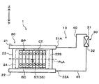
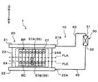
- the liquid-phase refrigerant temperature sensor 57 is disposed not in the heat exchange unit 23 of the device heat exchanger 20 but in the liquid-side pipe 45.
- the liquid-phase refrigerant temperature sensor 57 is disposed at a portion of the liquid-side pipe 45 close to the heat exchanger 20 for the device.
- liquid-phase refrigerant temperature sensor 57 is disposed at a portion of the liquid-phase side pipe 45 closer to the pipe connection portion 22A of the heat exchanger 20 for the device than the outlet 32 of the condenser 30 It is located lower in the direction of gravity than the appropriate liquid level FLA.
- the liquid phase refrigerant temperature sensor 57 can directly detect the temperature of the liquid phase refrigerant flowing into the pipe connection portion 22A of the liquid supply portion 22 in the heat exchanger 20 for the apparatus.
- the liquid-phase refrigerant temperature sensor 57 is connected to the input side of the device control device 50 as a refrigerant temperature sensor 55.
- the liquid phase refrigerant temperature sensor 57 according to the fourth embodiment corresponds to a liquid phase physical quantity detection unit.
- the temperature control apparatus 1 realizes continuous cooling of the battery pack BP by natural circulation of the refrigerant without requiring a driving device such as a compressor as in the above-described embodiments. Can.
- liquid surface position of the liquid phase refrigerant RL in the device heat exchanger 20 is at the appropriate liquid surface position FLA, as described with reference to FIG. It becomes wet throughout the vertical direction.
- the battery assembly BP can be cooled by the latent heat of vaporization of the liquid-phase refrigerant in the entire area of the heat exchange section 23 of the heat exchanger 20 for equipment.
- the refrigerant in the heat exchange unit 23 causes a phase change from liquid phase to gas phase due to latent heat, the entire refrigerant in the fluid circulation circuit 10 exhibits a constant temperature.
- the vapor-phase refrigerant evaporated below the heat exchange portion 23 is heated by the heat generated in the assembled battery BP when moving upward, and its temperature rises, so that the superheat (superheat ) State.
- the liquid level position of a liquid phase refrigerant falls, and the temperature as the whole refrigerant
- the temperature of the liquid phase refrigerant detected by the liquid phase refrigerant temperature sensor 57 in the liquid phase side pipe 45 increases. That is, based on the detection value of the liquid phase refrigerant temperature sensor 57 disposed in the liquid phase side pipe 45, the amount of refrigerant enclosed in the fluid circulation circuit 10 and the liquid level position of the liquid phase refrigerant in the heat exchanger 20 for equipment It can be estimated.
- the temperature adjustment device 1 can estimate that the liquid level position of the liquid phase refrigerant has dropped below the appropriate liquid level position FLA, and that the amount of refrigerant charged has decreased to a corresponding amount.
- the control process executed by the device control apparatus 50 when cooling the battery pack BP is replaced with the surface temperature TS and the reference surface temperature KTS in the third embodiment.
- the second embodiment is the same as the third embodiment described above except that the control of the initial liquid phase refrigerant temperature and the control map for setting the reference liquid phase refrigerant temperature are used.
- the refrigerant charge amount as a reference (the liquid phase refrigerant temperature detected by the liquid phase refrigerant temperature sensor 57 disposed in the liquid phase side pipe 45) That is, it is possible to accurately estimate the current amount of the refrigerant charged by using the appropriate sealed amount and the warning sealed amount).
- the notification device 51 notifies the user of that fact. Therefore, according to the said temperature control apparatus 1, the refrigerant
- the same advantages as those of the above-described embodiments can be obtained from the configurations and operations common to those of the above-described embodiments.
- the liquid-phase refrigerant temperature sensor 57 is disposed in the liquid-side pipe 45 at a portion close to the pipe connection portion 22A of the heat exchanger 20 for the device.
- the temperature adjustment device 1 can improve the workability relating to the operation of arranging the liquid-phase refrigerant temperature sensor 57 with respect to the liquid-phase side pipe 45 and maintenance.
- the arrangement of the liquid-phase refrigerant temperature sensor 57 in the temperature adjustment device 1 according to the third embodiment or the fourth embodiment described above can detect a physical quantity having a correlation with the temperature of the liquid-phase refrigerant in the fluid circulation circuit 10 And can be changed as appropriate.
- the liquid-phase refrigerant temperature sensor 57 as the refrigerant temperature sensor 55 can also be arranged at the arrangement position PLA or the arrangement position PLB shown in FIG.
- the arrangement position PLA indicates the liquid supply unit 22 located below the device heat exchanger 20.
- the liquid-phase refrigerant that has passed through the liquid-phase side pipe 45 flows from the pipe connection portion 22A into the liquid supply portion 22 of the heat exchanger 20 for the device. Therefore, by disposing the liquid-phase refrigerant temperature sensor 57 at the arrangement position PLA, it is possible to reliably detect a physical quantity that has a correlation with the temperature of the liquid-phase refrigerant.
- the arrangement position PLB indicates the periphery of the outlet 32 in the condenser 30.
- the liquid phase refrigerant condensed in the condenser 30 flows out to the liquid phase side pipe 45 at the outlet 32 of the condenser 30. Therefore, by disposing the liquid-phase refrigerant temperature sensor 57 at the arrangement position PLB, it is possible to reliably detect the physical quantity having a correlation with the temperature of the liquid-phase refrigerant.
- the liquid refrigerant temperature sensor 57 may be disposed at a plurality of locations in the fluid circulation circuit 10.
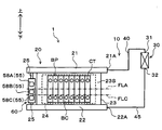
- thermosyphon type temperature control device 1 uses the battery pack BP mounted on a vehicle such as an electric vehicle as a target device and adjusts the temperature of the battery pack BP, as in the above-described embodiments. Applied as a device to
- the temperature adjustment device 1 includes the fluid circulation circuit 10 and the device control device 50, as in the above-described embodiments.
- the fluid circulation circuit 10 is configured to include an apparatus heat exchanger 20, a condenser 30, a gas phase side pipe 40, and a liquid phase side pipe 45.
- an upper liquid phase temperature sensor 57A and a lower liquid phase temperature sensor 57B are provided as the liquid phase refrigerant temperature sensor 57 which is the refrigerant temperature sensor 55.
- the other configuration is the same as that of the embodiment described above, and thus the description thereof is omitted.
- the upper liquid phase temperature sensor 57A and the lower liquid phase temperature sensor 57B are disposed on the surface of the heat exchange portion 23 in the heat exchanger 20 for the device.
- the upper liquid phase temperature sensor 57A and the lower liquid phase temperature sensor 57B detect the surface temperature TS at each arrangement position in the heat exchange unit 23 as a physical quantity having a correlation with the temperature of the liquid phase refrigerant.
- the upper liquid phase temperature sensor 57A and the lower liquid phase temperature sensor 57B are connected to the input side of the device control device 50 as the refrigerant temperature sensor 55.
- the upper liquid phase temperature sensor 57A corresponds to a liquid phase physical quantity detection unit and corresponds to an upper liquid phase physical quantity detection unit.
- the lower liquid phase temperature sensor 57B corresponds to a liquid phase physical quantity detection unit and to a lower liquid phase physical quantity detection unit.
- the upper liquid phase temperature sensor 57A is disposed, in the heat exchange section 23, on the upper side in the gravity direction of the warning liquid level FLC defined below the appropriate liquid level FLA.
- the warning liquid level position FLC corresponds to the warning reference position.
- the upper liquid phase temperature sensor 57A is the upper side in the gravity direction of the warning liquid level FLC in the heat exchange unit 23, and the lower side in the gravity direction than the proper liquid level FLA It is arranged at a position near the position FLA.
- the lower liquid phase temperature sensor 57B is disposed on the heat exchange unit 23 below the warning liquid level FLC in the gravity direction. More preferably, the lower liquid phase temperature sensor 57B is disposed below the warning liquid level FLC in the heat exchange section 23 in the direction of gravity and as close as possible to the warning liquid level FLC.
- This position is a position which appears early as a temperature change of the surface temperature TS, when the amount of charged refrigerant is smaller than the amount of charged warning related to the warning liquid level FLC. Therefore, by disposing the lower liquid phase temperature sensor 57B at this position, it is possible to detect early that the amount of refrigerant enclosed in the fluid circulation circuit 10 is smaller than the amount of alarm enclosed.
- the temperature control device 1 realizes continuous cooling of the battery pack BP by natural circulation of the refrigerant without requiring a driving device such as a compressor as in the above-described embodiment. it can.
- the portion to be cooled by the latent heat of vaporization of the liquid phase refrigerant decreases.
- the portion heated by the heat generated in the assembled battery BP is increased.
- the arrangement position of the upper liquid phase temperature sensor 57A contacts the gas phase refrigerant from the state of being in contact with the liquid phase refrigerant It will change to the state.
- the temperature control device 1 executes the control processing according to the third embodiment described above using the surface temperature TS detected by the upper liquid phase temperature sensor 57A, thereby circulating the fluid. It is possible to determine whether the amount of refrigerant charged in the circuit 10 decreases from the appropriate amount and the liquid level position of the liquid-phase refrigerant falls from the appropriate liquid level FLA. Since this point has already been described in the third embodiment, the description thereof will not be repeated.
- the liquid level position of the liquid-phase refrigerant in the heat exchanger 20 for equipment becomes the warning liquid level position FLC.
- the arrangement position of the upper liquid phase temperature sensor 57A is in contact with the gas phase refrigerant
- the arrangement position of the lower liquid phase temperature sensor 57B is in contact with the liquid phase refrigerant.
- the surface temperature TS detected by the upper liquid phase temperature sensor 57A indicates a temperature higher than the surface temperature TS detected by the lower liquid phase temperature sensor 57B.
- the temperature adjusting device 1 can measure the liquid in the heat exchanger 20 for the device based on the warning liquid level FLC. The liquid level position of the phase refrigerant can be estimated.
- a temperature difference between the surface temperature TS by the upper liquid phase temperature sensor 57A and the surface temperature TS by the lower liquid phase temperature sensor 57B is referred to as a surface temperature difference DTS. Since the surface temperature difference DTS is used, the arrangement position of the upper liquid phase temperature sensor 57A is preferably in a state where it does not get wet with the liquid phase refrigerant due to the boiling of the liquid phase refrigerant.
- the estimation of the liquid level position of the liquid-phase refrigerant using the surface temperature difference DTS is particularly effective when the battery heat generation amount Q of the battery pack BP which is the target device is small to some extent.
- the control process shown in the flowchart of FIG. 16 is realized by reading out the control program stored in the ROM of the device control device 50 and executing the control program by the device control device 50.
- the control process shown in FIG. 16 shows control contents for determining whether the amount of refrigerant charged in the fluid circulation circuit 10 is smaller than the amount of warning charge. As described above, the control process in the third embodiment is executed as to whether or not the refrigerant charge amount has decreased below the appropriate charge amount.
- step S21 the battery heating value Q of the battery pack BP is specified as in step S2 of the first embodiment.
- a reference surface temperature difference KDTS is set as a reference physical quantity corresponding to the surface temperature difference DTS using the battery heating value Q of the battery pack BP.
- the reference surface temperature difference KDTS is used as an evaluation standard for evaluating the amount of refrigerant enclosed in the fluid circulation circuit 10, and corresponds to a reference warning difference amount.
- the temperature change LA indicated by the solid line indicates the temperature change when the liquid level of the liquid-phase refrigerant in the heat exchanger 20 for equipment is at the appropriate liquid level FLA
- the temperature change LC indicated by the broken line show the temperature change in case the liquid level position of the liquid phase refrigerant
- the arrangement positions of the upper liquid phase temperature sensor 57A and the lower liquid phase temperature sensor 57B are both in contact with the liquid phase refrigerant State.
- the liquid-phase refrigerant evaporates to cause a change in latent heat, so the surface temperature difference DTS in this case is the time when the battery pack BP starts generating heat. Even if time passes from t0, the initial surface temperature difference DTS0 at time t0 is maintained.
- the arrangement position of the upper liquid phase temperature sensor 57A is in a state of being in contact with the gas phase refrigerant.
- the arrangement position of the phase temperature sensor 57B is in a state of being in contact with the liquid phase refrigerant.
- the surface temperature detected by the lower liquid phase temperature sensor 57B is a latent heat change due to the evaporation of the liquid phase refrigerant, and therefore, shows a constant value.
- the surface temperature detected by the upper liquid phase temperature sensor 57A is raised by the heat generated by the battery pack BP because the latent heat of vaporization by the liquid phase refrigerant does not act.
- the surface temperature difference DTS when the liquid level position of the liquid-phase refrigerant in the heat exchanger 20 for equipment is at the warning liquid level position FLC is larger as time passes from time t0 when the assembled battery BP starts heat generation. Indicates a value.
- DTS n which is the surface temperature difference at time t n when the determination regarding the refrigerant charge amount is performed can be specified, and this value can be set to the reference surface temperature difference KDTS. That is, the reference surface temperature difference KDTS when the warning enclosed amount is enclosed can be specified using the battery heat generation amount Q as a parameter.
- a control map in which the reference surface temperature difference KDTS is associated with the battery heating value Q is created in advance by measurement or calculation.
- the control map is stored in the ROM of the device control device 50.
- step S22 the control map stored in the ROM of the device control apparatus 50 is read out, and the reference surface temperature difference KDTS is specified using the battery heat generation amount Q specified in step S21.
- the device control apparatus 50 that executes step S22 functions as a reference value setting unit 50B and corresponds to a reference physical quantity setting unit.
- the upper liquid phase temperature sensor 57A and the lower liquid phase temperature sensor 57B detect the surface temperature TS at each position. And surface temperature difference DTS in heat exchange part 23 of heat exchanger 20 for apparatus at present is computed from two detected surface temperature TS.
- step S24 it is determined whether or not the current surface temperature difference DTS is higher than the reference surface temperature difference KDTS related to the warning enclosed amount.
- the current surface temperature difference DTS is higher than the reference surface temperature difference KDTS, the current refrigerant charge amount is smaller than the warning charge amount, and the liquid level position of the liquid-phase refrigerant in the heat exchanger 20 for equipment is the warning liquid level position FLC It can be estimated that it is located lower than it.
- the current refrigerant charge amount is equal to or larger than the warning charge amount, and the liquid level position of the liquid phase refrigerant in the device heat exchanger 20 is the same as the warning liquid level FLC or above the warning liquid level FLC. It can be estimated that Thereafter, this control process is ended.
- the device control apparatus 50 in the case of executing step S24 functions as the fluid volume estimation unit 50C and the decrease determination unit 50D as in the above-described embodiment, and corresponds to the fluid volume estimation unit and the decrease determination unit.
- step S25 a warning signal output according to the determination result of step S24 is output to the notification device 51.
- the notification device 51 notifies the user that the current refrigerant charge amount is smaller than the warning charge amount by the voice output unit and the information display unit.
- the same advantages as those of the above-described embodiments can be obtained from the same configuration and operation as those of the above-described embodiments.
- the temperature adjustment device 1 has an upper liquid phase temperature sensor 57A and a lower liquid phase temperature sensor 57B as the liquid phase refrigerant temperature sensor 57.
- the upper liquid phase temperature sensor 57A is arranged above the warning liquid level FLC in the heat exchange section 23 in the direction of gravity
- the lower liquid phase temperature sensor 57B is in the heat exchange section 23 at the warning liquid level FLC. It is arranged on the lower side in the direction of gravity.
- the liquid level position of the liquid phase refrigerant at the present time point is estimated based on the warning liquid level position FLC. Can.
- both the upper liquid phase temperature sensor 57A and the lower liquid phase temperature sensor 57B are disposed below the appropriate liquid level FLA in the heat exchange unit 23. Therefore, according to the said temperature control apparatus 1, the liquid level position of the liquid phase refrigerant
- the liquid level of the liquid-phase refrigerant in the heat exchanger 20 for the device is estimated using the two references of the appropriate liquid level position FLA and the warning liquid level position FLC. It is possible to control the amount of refrigerant charged in the fluid circulation circuit 10 in more detail.
- thermosyphon type temperature adjustment device 1 uses the battery pack BP mounted on a vehicle such as an electric vehicle as a target device and adjusts the temperature of the battery pack BP, as in the above-described embodiments. Applied as a device to
- the temperature adjustment device 1 includes the fluid circulation circuit 10 and the device control device 50, as in the above-described embodiments.
- the fluid circulation circuit 10 is configured to include a device heat exchanger 20, a condenser 30, a gas phase side pipe 40, and a liquid phase side pipe 45.
- the temperature adjustment device 1 has a gas phase refrigerant temperature sensor 56 and a liquid phase refrigerant temperature sensor 57 as the refrigerant temperature sensor 55.
- the other configuration is the same as that of the embodiment described above, and thus the description thereof is omitted.
- the vapor-phase refrigerant temperature sensor 56 is the same as the second embodiment, in the vapor-phase side piping 40, heat for equipment than the inlet portion 31 of the condenser 30. It is arrange
- the gas phase refrigerant temperature sensor 56 can directly detect the temperature of the gas phase refrigerant flowing out from the pipe connection portion 21A of the fluid outflow portion 21 in the heat exchanger 20 for an apparatus.
- the gas phase refrigerant temperature sensor 56 is connected to the input side of the device control device 50 as a refrigerant temperature sensor 55.
- liquid phase refrigerant temperature sensor 57 concerning a 6th embodiment is piping of heat exchanger 20 for apparatus rather than outlet part 32 of condenser 30 among liquid phase side piping 45 like a 4th embodiment. It is arrange
- the liquid phase refrigerant temperature sensor 57 can directly detect the temperature of the liquid phase refrigerant flowing into the pipe connection portion 22A of the liquid supply portion 22 in the heat exchanger 20 for the apparatus.
- the liquid-phase refrigerant temperature sensor 57 is connected to the input side of the device control device 50 as a refrigerant temperature sensor 55.
- the gas phase refrigerant temperature sensor 56 according to the sixth embodiment corresponds to a gas phase physical quantity detection unit
- the liquid phase refrigerant temperature sensor 57 corresponds to a liquid phase physical quantity detection unit.
- the temperature control apparatus 1 realizes continuous cooling of the battery pack BP by natural circulation of the refrigerant without requiring a driving device such as a compressor as in the above-described embodiment. it can.
- the heat exchange portion 23 is in the liquid phase over the entire vertical direction. It gets wet with the refrigerant. At this time, inside the device heat exchanger 20, the refrigerant changes its phase from the liquid phase to the gas phase due to the heat generation of the battery pack BP, so the temperatures of the liquid phase refrigerant and the gas phase refrigerant show similar values.
- the gas phase refrigerant evaporated below the heat exchange portion 23 is heated for a long time by the heat generated in the assembled battery BP as the liquid level position of the liquid phase refrigerant decreases. Therefore, as the liquid level position of the liquid phase refrigerant decreases from the appropriate liquid level position FLA, the gas phase refrigerant temperature detected by the gas phase refrigerant temperature sensor 56 rises, and the gas phase refrigerant is in a superheated (superheat) state It becomes.
- the gas phase refrigerant temperature becomes higher than the liquid phase refrigerant temperature. That is, as the liquid level position of the liquid phase refrigerant in the device heat exchanger 20 decreases, a large temperature difference occurs between the gas phase refrigerant and the liquid phase refrigerant.
- the liquid level position of the liquid phase refrigerant in the heat exchanger 20 for equipment is estimated by using the temperature difference between the gas phase refrigerant and the liquid phase refrigerant circulating in the fluid circulation circuit 10 (that is, the refrigerant temperature difference DTR described later)
- the amount of refrigerant charged in the fluid circulation circuit 10 can be estimated.
- the control process shown in the flowchart of FIG. 19 is realized by reading out the control program stored in the ROM of the device control device 50 and executing the control program by the device control device 50.
- step S31 as in step S2 of the first embodiment, the battery heating value Q of the assembled battery BP is specified.
- a reference refrigerant temperature difference KDTR is set as a reference physical quantity corresponding to the refrigerant temperature difference DTR using the battery heat generation amount Q of the assembled battery BP.
- the reference refrigerant temperature difference KDTR is used as an evaluation standard for evaluating the amount of refrigerant enclosed in the fluid circulation circuit 10, and corresponds to the reference difference.
- the refrigerant temperature difference DTR means the difference value between the gas phase refrigerant temperature detected by the gas phase refrigerant temperature sensor 56 and the liquid phase refrigerant temperature detected by the liquid phase refrigerant temperature sensor 57.
- the refrigerant temperature difference DTR corresponds to a difference physical quantity.
- the time change of the refrigerant temperature difference DTR due to the heat generation of the assembled battery BP will be described with reference to FIG.
- a temperature change LA shown by a solid line shows a temperature change when the liquid level position of the liquid phase refrigerant in the heat exchanger 20 for equipment is at the proper liquid level position FLA
- a temperature change LC shown by a broken line show the temperature change in case the liquid level position of the liquid phase refrigerant
- the temperature difference between the gas phase refrigerant and the liquid phase refrigerant shows a constant value.
- the refrigerant temperature difference at time t0 at the start of heat generation of the battery pack BP tends to be maintained.
- the value of the refrigerant temperature difference DTR also increases.
- the degree of temperature rise of the gas phase refrigerant also increases, so the degree of increase of the refrigerant temperature difference DTR also increases.
- the refrigerant temperature difference DTR when the liquid level is at the warning liquid level FLC tends to increase as time passes from time t0.
- the temporal change of the respective refrigerant temperature differences DTR The refrigerant temperature difference DTRn at the time tn when the determination regarding the refrigerant charge amount is performed can be specified respectively, and this value can be set as the reference refrigerant temperature difference.
- the reference refrigerant temperature difference KDTR in the sixth embodiment can be specified using the battery heat generation amount Q as a parameter.
- a control map in which the reference refrigerant temperature difference KDTR and the battery heating value Q are associated with each other is created in advance by measurement or calculation.
- the control map is stored in the ROM of the device control device 50.
- step S32 the control map stored in the ROM of the device control apparatus 50 is read out, and the reference refrigerant temperature difference KDTR is identified using the battery heat generation amount Q identified in step S31.
- the reference refrigerant temperature difference KDTR related to the warning enclosed amount is specified.
- the device control apparatus 50 that executes step S32 functions as a reference value setting unit 50B and corresponds to a reference physical quantity setting unit.
- the gas phase refrigerant temperature sensor 56 and the liquid phase refrigerant temperature sensor 57 detect the gas phase refrigerant temperature and the liquid phase refrigerant temperature, respectively. Then, the refrigerant temperature difference DTR at the present time is calculated from the detected gas phase refrigerant temperature and liquid phase refrigerant temperature.
- step S34 it is determined whether or not the current refrigerant temperature difference DTR is higher than the reference refrigerant temperature difference KDTR related to the warning enclosed amount.
- the refrigerant temperature difference DTR at the present time is higher than the reference refrigerant temperature difference KDTR, the refrigerant charge amount at the present time is smaller than the warning charge amount, and the liquid level position of the liquid phase refrigerant in the heat exchanger 20 for equipment is the warning liquid level position FLC It can be estimated that it is located lower than it.
- the current refrigerant charge amount is equal to or larger than the warning charge amount, and the liquid level position of the liquid phase refrigerant in the device heat exchanger 20 is the same as the warning liquid level FLC or above the warning liquid level FLC. It can be estimated that Thereafter, this control process is ended.
- the device control device 50 in the case of executing step S34 functions as the fluid volume estimation unit 50C and the decrease determination unit 50D as in the above-described embodiment, and corresponds to the fluid volume estimation unit and the decrease determination unit.
- step S35 the warning signal output according to the determination result of step S34 is output to the notification device 51.
- the notification device 51 notifies the user that the current refrigerant charge amount is smaller than the warning charge amount by the voice output unit and the information display unit.
- this control process is ended.
- step S32 if the reference refrigerant temperature difference KDTR relating to the appropriate enclosed amount is specified, and if it is compared with the refrigerant temperature difference DTR at the present time in step S34, is the refrigerant enclosed amount at the current time smaller than the appropriate enclosed amount? It is also possible to estimate whether or not.
- the temperature adjustment device 1 As described above, according to the temperature adjustment device 1 according to the sixth embodiment, it is possible to obtain the same effects as those of the above-described embodiments, from the configuration and operation common to the above-described embodiments.
- the temperature adjusting device 1 includes a gas phase refrigerant temperature sensor 56 and a liquid phase refrigerant temperature sensor 57.
- the temperature adjustment device 1 calculates the refrigerant temperature difference DTR from the gas phase refrigerant temperature detected by the gas phase refrigerant temperature sensor 56 and the liquid phase refrigerant temperature detected by the liquid phase refrigerant temperature sensor 57, and the refrigerant temperature difference DTR To estimate the liquid level position of the liquid phase refrigerant at the present time.
- the said temperature adjustment apparatus 1 utilizes the difference of the difference value of the physical quantity which has a correlation with the temperature of the liquid phase refrigerant in the fluid circulation circuit 10, and the gas phase refrigerant, and the liquid level position of the liquid phase refrigerant in the present time It can be estimated with reference to the proper liquid level FLA, the warning liquid level FLC, and the like.
- the temperature adjustment device 1 by estimating the liquid level position of the liquid phase refrigerant at the present time, it is possible to estimate the refrigerant charged amount in the fluid circulation circuit 10 at the present time, and managing the refrigerant charged amount be able to.
- the gas phase refrigerant temperature sensor 56 is disposed on the upper side in the gravity direction than the appropriate liquid level position FLA and the warning liquid level position FLC, and the liquid phase refrigerant temperature sensor 57 is an appropriate liquid It is disposed below the surface position FLA and the warning liquid surface position FLC in the direction of gravity.
- the temperature of the gas phase refrigerant circulating in the fluid circulation circuit 10 can be reliably detected by the gas phase refrigerant temperature sensor 56, and the fluid circulation temperature sensor 57 causes the fluid circulation The temperature of the liquid phase refrigerant circulating in the circuit 10 can be detected reliably.
- the gas phase refrigerant temperature sensor 56 is disposed in the gas phase side pipe 40, and the liquid phase refrigerant temperature sensor 57 is disposed in the liquid phase side piping 45.
- the gas phase side piping 40 and the liquid phase side piping 45 correspond to portions with good workability, so the arrangement of the gas phase refrigerant temperature sensor 56 with respect to the gas phase side piping 40 and the liquid phase side piping 45
- coolant temperature sensor 57, and maintenance can be improved.
- the arrangement of the gas phase refrigerant temperature sensor 56 and the liquid phase refrigerant temperature sensor 57 is merely an example.
- the arrangement of the gas phase refrigerant temperature sensor 56 can be appropriately changed as long as it can detect a physical quantity that has a correlation with the temperature of the gas phase refrigerant in the fluid circulation circuit 10.
- the gas phase refrigerant temperature sensor 56 can be disposed at the placement position PGA or the placement position PGB shown in FIG.
- the arrangement position PGA and the arrangement position PGB have already been described with reference to FIG.
- gas phase refrigerant temperature sensor 56 may be arranged at the arrangement position PGC shown in FIG.
- the arrangement position PGC indicates the gravity direction upper side of at least the appropriate liquid surface position FLA in the heat exchange unit 23 of the heat exchanger 20 for the device.
- the arrangement position PGC be a position above the appropriate liquid surface position FLA in the heat exchange unit 23 and close to the upper end of the battery pack BP that is the target device.
- the arrangement of the liquid phase refrigerant temperature sensor 57 can be appropriately changed as long as it is possible to detect a physical quantity having a correlation with the temperature of the liquid phase refrigerant in the fluid circulation circuit 10.
- liquid-phase refrigerant temperature sensor 57 at the disposition position PLA or the disposition position PLB shown in FIG.
- the arrangement position PLA and the arrangement position PLB have already been described with reference to FIG.
- liquid phase refrigerant temperature sensor 57 in arrangement position PLC shown in FIG.
- the arrangement position PLC indicates the lower side in the gravity direction than at least the appropriate liquid surface position FLA in the heat exchange unit 23 of the heat exchanger 20 for the device.
- the arrangement position PLC be a portion below the appropriate liquid surface position FLA in the heat exchange unit 23 and further below the lower end of the assembled battery BP.
- the gas phase refrigerant temperature sensor 56 is arranged at any one of the arrangement position PGA to the arrangement position PGC shown in FIG. 21 and the liquid phase refrigerant temperature sensor is arranged at any one position of the arrangement position PLA to the arrangement position PLA.
- 57 may be arranged. The combination of the arrangement positions can be changed as appropriate.
- thermosyphon type temperature adjustment device 1 uses the battery pack BP mounted in a vehicle such as an electric vehicle as a target device and adjusts the temperature of the battery pack BP, as in the above-described embodiments. Applied as a device to
- the temperature adjustment device 1 includes the fluid circulation circuit 10 and the device control device 50, as in the above-described embodiments.
- the fluid circulation circuit 10 is configured to include an apparatus heat exchanger 20, a condenser 30, a gas phase side pipe 40, and a liquid phase side pipe 45.
- the temperature control apparatus includes, as the refrigerant temperature sensor 55, a gas phase refrigerant temperature sensor 56 and a liquid phase refrigerant temperature sensor 57.
- the liquid phase refrigerant temperature sensor 57 according to the seventh embodiment includes an upper liquid phase temperature sensor 57A and a lower liquid phase temperature sensor 57B.
- the other configuration is the same as that of the embodiment described above, and thus the description thereof is omitted.
- the gas phase refrigerant temperature sensor 56 is a heat exchange portion 23 of the heat exchanger 20 for an apparatus, which is a gravity direction upper side with respect to the appropriate liquid level FLA. It is arrange
- the gas-phase refrigerant temperature sensor 56 detects the temperature of the gas-phase refrigerant evaporated inside the device heat exchanger 20. Therefore, the gas phase refrigerant temperature sensor 56 corresponds to a gas phase physical quantity detection unit.
- the upper liquid phase temperature sensor 57A is disposed below the appropriate liquid surface position FLA in the direction of gravity in the heat exchange section 23 of the heat exchanger 20 for equipment, and above the warning liquid surface position FLC in the direction of gravity. ing.
- the warning liquid level FLC according to the seventh embodiment corresponds to a warning reference position.
- the upper liquid phase temperature sensor 57A detects the temperature of the liquid phase refrigerant inside the heat exchanger 20 for the device. Therefore, the upper liquid phase temperature sensor 57A corresponds to one of the liquid phase physical quantity detection unit and corresponds to the upper liquid phase physical quantity detection unit.
- the lower liquid phase temperature sensor 57B is disposed below the warning liquid level FLC in the direction of gravity in the heat exchange unit 23 of the heat exchanger 20 for the device.
- the lower liquid phase temperature sensor 57 ⁇ / b> B detects the temperature of the liquid phase refrigerant on the lower side of the heat exchange unit 23 inside the device heat exchanger 20. Accordingly, the lower liquid phase temperature sensor 57B corresponds to the liquid phase physical quantity detection unit and to the lower liquid phase physical quantity detection unit.
- the temperature control device 1 realizes continuous cooling of the battery pack BP by natural circulation of the refrigerant without requiring a driving device such as a compressor as in the above-described embodiment. it can.
- coolant temperature sensor 56 and the upper liquid phase temperature sensor 57A shows the tendency similar to the graph shown in FIG. That is, the refrigerant temperature difference between the gas phase refrigerant temperature sensor 56 and the upper liquid phase temperature sensor 57A with the passage of time as the liquid level position of the liquid phase refrigerant in the heat exchanger 20 for equipment falls below the appropriate liquid level FLA. Becomes larger.
- the same tendency is indicated for the temporal change of the refrigerant temperature difference by the upper liquid phase temperature sensor 57A and the lower liquid phase temperature sensor 57B. That is, the refrigerant temperature in the upper liquid phase temperature sensor 57A and the lower liquid phase temperature sensor 57B with the passage of time as the liquid level position of the liquid phase refrigerant in the device heat exchanger 20 falls below the warning liquid level position FLC. The difference tends to increase.
- the refrigerant temperature difference between the upper liquid phase temperature sensor 57A and the lower liquid phase temperature sensor 57B corresponds to the difference liquid phase physical quantity.
- the refrigerant temperature difference at time tn can be identified from the temporal change of the refrigerant temperature difference by the gas phase refrigerant temperature sensor 56 and the upper liquid phase temperature sensor 57A, and the liquid level of the liquid phase refrigerant is at the appropriate liquid level position FLA.
- the reference refrigerant temperature difference in a certain case can be identified.
- the refrigerant temperature difference at time tn can be specified from the temporal change of the refrigerant temperature difference by the upper liquid phase temperature sensor 57A and the lower liquid phase temperature sensor 57B.
- coolant exists in warning liquid level position FLC can be specified.
- the reference refrigerant temperature difference relating to the appropriate sealing amount and the reference refrigerant temperature difference relating to the warning sealing amount using the battery heat generation amount Q as a parameter.
- the reference refrigerant temperature difference relating to the warning enclosed amount corresponds to the reference warning difference amount.
- a control map in which the reference refrigerant temperature difference relating to the appropriate enclosed amount and the battery heat generation amount Q are associated, the reference refrigerant temperature difference relating to the warning enclosed amount, and the battery generated amount Q And control maps associated with each other are created in advance by measurement or calculation.
- the control maps are all stored in the ROM of the device control apparatus 50.
- the refrigerant temperature difference at the present time by the gas phase refrigerant temperature sensor 56 and the upper liquid phase temperature sensor 57A is compared with the reference refrigerant temperature difference related to the appropriate filling amount.
- the reference refrigerant temperature difference related to the appropriate filling amount it can be determined whether or not the liquid level of the liquid phase refrigerant at the current time point is lower than the appropriate liquid level position FLA.
- the temperature adjustment device 1 compares the current refrigerant temperature difference by the upper liquid phase temperature sensor 57A and the lower liquid phase temperature sensor 57B with the reference refrigerant temperature difference relating to the amount of enclosed warning, thereby the liquid at the current time. It can be determined whether the liquid level of the phase refrigerant is lower than the warning liquid level FLC and is smaller than the warning enclosed amount.
- the temperature adjustment device 1 outputs a control signal (that is, a notification signal or a warning signal) based on the determination results to the notification device 51, thereby allowing the user of the refrigerant circulation amount of the fluid circulation circuit 10 at the current time to be Can be informed or warned.
- a control signal that is, a notification signal or a warning signal
- control process in the seventh embodiment are basically the same as the flowchart shown in FIG. 19, and thus the illustration and the detailed description will be omitted.
- the same advantages as those of the above-described embodiments can be obtained from the configuration and operation common to those of the above-described embodiments.
- the temperature adjusting device 1 includes, as the refrigerant temperature sensor 55, a gas phase refrigerant temperature sensor 56, an upper liquid phase temperature sensor 57A, and a lower liquid phase temperature sensor 57B.
- the temperature adjustment device 1 uses the refrigerant temperature difference between the gas phase refrigerant temperature sensor 56 and the upper liquid phase temperature sensor 57A and the reference refrigerant temperature difference relating to the appropriate enclosed amount, and uses the appropriate liquid surface position FLA as a reference It is possible to estimate the liquid level position of the liquid phase refrigerant in
- the temperature adjustment device 1 uses the refrigerant temperature difference between the upper liquid phase temperature sensor 57A and the lower liquid phase temperature sensor 57B and the reference refrigerant temperature difference relating to the amount of enclosed warning to reference the warning liquid level FLC. As, it is possible to estimate the liquid level position of the liquid phase refrigerant at the present time.
- the temperature adjustment device 1 by estimating the liquid level position of the liquid phase refrigerant at the present time, the refrigerant charge amount in the fluid circulation circuit 10 at the present time can be estimated more accurately, and management of the refrigerant charge amount It can be performed.
- thermosyphon type temperature control device 1 uses the battery pack BP mounted on a vehicle such as an electric vehicle as a target device and adjusts the temperature of the battery pack BP, as in the above-described embodiments. Applied as a device to
- the temperature adjustment device 1 includes the fluid circulation circuit 10 and the device control device 50, as in the above-described embodiments.
- the fluid circulation circuit 10 is configured to include an apparatus heat exchanger 20, a condenser 30, a gas phase side pipe 40, and a liquid phase side pipe 45.
- the temperature adjustment device 1 according to the eighth embodiment differs from the above-described embodiment in the configuration of the device heat exchanger 20 and the refrigerant temperature sensor 55 as shown in FIG.
- the other configuration is the same as that of the embodiment described above, and thus the description thereof is omitted.
- the heat exchanger 20 for equipment according to the eighth embodiment is added to the fluid outflow portion 21, the liquid supply portion 22, the heat exchange portion 23, and the heat conduction sheet 24 configured similarly to the above-described embodiment, A detection tube 25 is provided.
- the detection tube 25 is disposed between the fluid outflow portion 21 and the liquid supply portion 22 in the direction of gravity, and is made of a metal material having excellent thermal conductivity, like the tube 23A that constitutes the heat exchange portion 23. It is formed in a tubular shape.
- the detection tube 25 connects the inside of the fluid outlet 21 and the inside of the liquid supply unit 22. Therefore, as shown in FIG. 24, the liquid level of the liquid phase refrigerant is present at the same position as the liquid level position of the liquid phase refrigerant in the heat exchange unit 23 inside the detection tube 25.
- the detection tube 25 corresponds to a detection flow path.
- a first temperature sensor 58A, a second temperature sensor 58B, and a third temperature sensor 58C are disposed on the outer peripheral surface of the detection tube 25.
- the first temperature sensor 58A to the third temperature sensor 58C are in thermal contact with the detection tube 25 at their respective arrangement positions, and are configured to detect the temperature of the refrigerant inside the detection tube 25. It is done.
- the first temperature sensor 58A to the third temperature sensor 58C are arranged side by side in the gravity direction in the detection tube 25.
- the first temperature sensor 58A is located on the detection tube 25 above the appropriate liquid surface position FLA in the heat exchanger 20 for the device in the gravity direction.
- the second temperature sensor 58B is disposed below the appropriate liquid level FLA in the heat exchanger 20 for the apparatus in the direction of gravity in the detection tube 25 and above the warning liquid level FLC in the direction of gravity. It is done. Therefore, the second temperature sensor 58B is located below the first temperature sensor 58A in the gravity direction.
- the third temperature sensor 58C is disposed below the warning liquid level FLC in the heat exchanger 20 for the device in the gravity direction in the detection tube 25. Therefore, the third temperature sensor 58C is located lower in the direction of gravity than the first temperature sensor 58A and the second temperature sensor 58B.
- the first temperature sensor 58A to the third temperature sensor 58C are connected to the input side of the device control device 50, respectively. Therefore, the first temperature sensor 58A to the third temperature sensor 58C correspond to physical quantity detection units and to a plurality of detection units, respectively.
- a sensor holder 61 is disposed on the detection tube 25 so as to cover the first temperature sensor 58A to the third temperature sensor 58C.
- the sensor holding body 61 is formed, for example, in a sheet shape having a predetermined viscosity.
- the sensor holder 61 has a function of holding the first temperature sensor 58A to the third temperature sensor 58C at predetermined positions in the detection tube 25 and a function of suppressing the thermal resistance between the heating device 60 and the detection tube 25 described later. have.
- a heating device 60 is disposed in the detection tube 25.
- the heating device 60 is composed of an electric heater that generates heat when energized, and is disposed outside the sensor holder 61.
- the heating device 60 is arranged so as to include the arrangement positions of the first temperature sensor 58A to the third temperature sensor 58C, and is configured to uniformly heat any position.
- the sensor holder 61 has a function of suppressing the thermal resistance between the heating device 60 and the detection tube 25, the heat generated by the heating device 60 is detected by the sensor holder 61 and the detection tube. The refrigerant is transmitted to the inside of the detection tube 25 through the 25 tube walls.
- the said heating apparatus 60 is comprised with the electric heater of the variable type from which emitted-heat amount changes according to the electricity supply amount.
- the amount of current supplied to the heating device 60 is controlled in accordance with a control signal from the device control device 50.
- the heating device 60 corresponds to a heating unit.
- the control process shown in the flowchart of FIG. 25 is realized by reading out the control program stored in the ROM of the device control device 50 and executing the control program by the device control device 50.
- the timing of executing the control process according to the eighth embodiment is not limited to the case of cooling the battery pack BP which is the target device.
- the control process may be performed when the vehicle is started, and may be performed at any time desired by the user.
- step S41 a heating start signal is output to the heating device 60.
- the heating device 60 heats the refrigerant in the detection tube 25 with a predetermined amount of heat.
- step S42 the refrigerant temperature inside the detection tube 25 is detected by the first temperature sensor 58A to the third temperature sensor 58C.
- step S43 it is determined whether or not a predetermined heating period has elapsed from the start of heating by the heating device 60. If the heating period has not elapsed, the process returns to step S41, and heating by the heating device 60 is continued.
- the first change amount TCA, the second change amount TCB, and the third change amount TCC are calculated using the refrigerant temperatures detected by the first temperature sensor 58A to the third temperature sensor 58C.
- the first change amount TCA refers to a change amount from the start of heating of the heating device 60 to the end of the heating period with respect to the refrigerant temperature detected by the first temperature sensor 58A.
- the second change amount TCB means a change amount from the start of heating of the heating device 60 to the end of the heating period with respect to the refrigerant temperature detected by the second temperature sensor 58B.
- the third change amount TCC means a change amount from the start of heating of the heating device 60 to the end of the heating period with respect to the refrigerant temperature detected by the third temperature sensor 58C.
- step S45 it is determined whether or not the first change amount TCA, the second change amount TCB, and the third change amount are equal.
- the fact that the first change amounts TCA and the like in the eighth embodiment are equal is not limited to the case where the values are completely the same, but includes a constant error.
- the magnitude of this error can be determined according to the amount of heat by the heating device 60, the environment of the vehicle during the heating period, and the like.
- the liquid-phase refrigerant is in contact at all at the arrangement positions of the first temperature sensor 58A to the third temperature sensor 58C. Means This is because the heat from the heating device 60 is used for the phase change of the liquid phase refrigerant at any arrangement position.
- step S45 it is determined whether the liquid level position of the liquid phase refrigerant at the current time point is located above the appropriate liquid level position FLA. If it is determined in step S45 that the first change amount TCA, the second change amount TCB, and the third change amount are equal to each other, the control process is ended because the amount of the refrigerant charged in the fluid circulation circuit 10 is sufficient.
- step S46 it is determined whether the first change amount TCA is larger than the second change amount TCB and the second change amount TCB is equal to the third change amount TCC.
- the gas-phase refrigerant is in contact with the first temperature sensor 58A
- the liquid-phase refrigerant is in contact with the second temperature sensor 58B and the third temperature sensor 58C. Do.
- the heat from the heating device 60 can not utilize the latent heat of vaporization of the liquid phase refrigerant, and raises the temperature of the gas phase refrigerant to bring it into an overheated state.
- the heat from the heating device 60 causes a change in latent heat that evaporates the liquid phase refrigerant, and therefore hardly raises the temperature of the liquid phase refrigerant .
- step S46 it is determined whether the liquid surface of the liquid-phase refrigerant in the device heat exchanger 20 is located between the arrangement position of the first temperature sensor 58A and the arrangement position of the second temperature sensor 58B. ing. In other words, it is determined whether or not the liquid level position of the liquid phase refrigerant at the present time has decreased to the appropriate liquid level position FLA.
- step S47 a notification signal is output to the notification device 51 based on the determination result of step S46.
- the notification device 51 notifies the user that the current amount of filled refrigerant is smaller than the appropriate amount of filling, by means of the voice output unit and the information display unit.
- step S48 it is determined whether the first change amount TCA is larger than the third change amount TCC and the second change amount TCB is larger than the third temperature sensor 58C.
- the determination condition is that the gas phase refrigerant is in contact at the arrangement position of the first temperature sensor 58A and the second temperature sensor 58B, and the liquid phase refrigerant is in contact at the arrangement position of the third temperature sensor 58C.
- the heat by the heating device 60 can not utilize the latent heat of vaporization of the liquid phase refrigerant, thereby raising the temperature of the gas phase refrigerant and causing overheating. Put in a state. Then, at the arrangement position of the third temperature sensor 58C, the heat from the heating device 60 changes the latent heat that evaporates the liquid phase refrigerant, so the temperature of the liquid phase refrigerant is hardly raised.
- step S48 it is determined whether or not the liquid surface of the liquid-phase refrigerant in the device heat exchanger 20 is positioned between the arrangement position of the second temperature sensor 58B and the arrangement position of the third temperature sensor 58C. ing. In other words, it is determined whether or not the liquid level position of the liquid phase refrigerant at the present time has decreased to the warning liquid level position FLC.
- step S49 a warning signal is output to the notification device 51 based on the determination result of step S48.
- the notification device 51 warns the user that the current refrigerant charge amount is smaller than the warning charge amount by the voice output unit and the information display unit.
- this control process is ended.
- the determination regarding the appropriate liquid level position FLA and the warning liquid level position FLC is performed using the first temperature sensor 58A to the third temperature sensor 58C, the present invention is not limited to this aspect. . By using at least two temperature sensors, determination regarding one reference liquid level position (for example, the appropriate liquid level FLA or the warning liquid level FLC) can be performed.
- the temperature adjustment device 1 according to the eighth embodiment it is possible to obtain, in the same manner as in the above-described embodiment, the same advantages as those of the above-described embodiment.
- the temperature adjusting device 1 has the first temperature sensor 58A to the third temperature sensor 58C as the refrigerant temperature sensor 55, and the arrangement positions of the first temperature sensor 58A to the third temperature sensor 58C are In the range which contains, the heating apparatus 60 which heats the refrigerant
- the temperature adjusting device 1 heats the refrigerant in the fluid circulation circuit 10 by the heating device 60, and uses the temperature change detected by the first temperature sensor 58A to the third temperature sensor 58C to detect the liquid level of the liquid phase refrigerant at the current time. The position can be estimated.
- first temperature sensor 58A to the third temperature sensor 58C and the heating device 60 are disposed with respect to the detection tube 25 connecting the fluid outflow portion 21 and the liquid supply portion 22 of the device heat exchanger 20.
- the temperature adjustment device 1 estimates the refrigerant charge amount using the heating device 60 and the first temperature sensor 58A to the third temperature sensor 58C while maintaining the temperature adjustment performance with respect to the battery pack BP which is the target device. It can be realized.
- the arrangement of the heating device 60 and the first temperature sensor 58A to the third temperature sensor 58C in the eighth embodiment is merely an example.
- the first temperature sensor 58A to the third temperature sensor 58C can be appropriately changed as long as the time change of the refrigerant temperature in the fluid circulation circuit 10 can be detected.
- the heating device 60 may be disposed so as to include the disposed positions of the first temperature sensor 58A to the third temperature sensor 58C as long as the refrigerant in the fluid circulation circuit 10 can be heated.
- the first temperature sensor 58A to the third temperature sensor 58C and the heating device 60 are disposed with respect to the detection tube 25 in the device heat exchanger 20, as shown in FIG. These may be disposed on the side surface of the heat exchange unit 23 of the heat exchanger 20 for equipment.
- the side surface portion of the heat exchange portion 23 is made of a metal material excellent in thermal conductivity, and the first temperature sensor 58A to the third temperature sensor 58C are in thermal contact with the side surface portion. Is located in
- the positional relationship between the appropriate liquid surface position FLA and the warning liquid surface position FLC with respect to the first temperature sensor 58A to the third temperature sensor 58C according to the first modification is the same as that of the eighth embodiment.
- the configuration and arrangement of the heating device 60 and the sensor holder 61 and the contents of the control process are also the same as in the eighth embodiment.
- a bypass flow passage 26 is disposed in the device heat exchanger 20.
- the upper end portion of the bypass flow passage 26 is connected to the pipe connection portion 21B at the fluid outflow portion 21 of the heat exchanger 20 for the device.
- the lower end of the bypass flow passage 26 is connected to the pipe connection portion 22B in the liquid supply portion 22 of the heat exchanger 20 for the device.
- the pipe connection portion 21B is disposed at the fluid outlet portion 21 at the opposite end of the pipe connection portion 21A, and the pipe connection portion 22B is disposed at the liquid supply portion 22 at the opposite end portion of the pipe connection portion 22A. It is done. That is, the bypass flow passage 26 is connected in parallel to the condenser 30 with respect to the heat exchanger 20 for the device.
- the same refrigerant as the refrigerant in the heat exchanger 20 for equipment is present inside the bypass flow passage 26, and the liquid surface is at the same position as the liquid level position of the liquid phase refrigerant in the heat exchanger 20 for equipment Will be located.
- the first temperature sensor 58A to the third temperature sensor 58C, the heating device 60, and the sensor holder 61 are disposed on the outer surface of the bypass flow path 26.
- the arrangement mode of these is the same as that of the eighth embodiment, and the detection tube 25 in FIG. 24 is a pipe constituting the bypass flow passage 26.
- the temperature adjusting device 1 according to the second modification configured as described above performs the control process of the eighth embodiment shown in FIG. 25 to obtain the same effects as the eighth embodiment described above.
- the effects can be obtained as in the eighth embodiment.
- the heating device 60 heats the liquid phase refrigerant in the bypass flow passage 26 to heat and warm up the battery pack BP which is the target device. it can.
- the liquid-phase refrigerant evaporates inside the bypass flow path 26.
- the vapor-phase refrigerant due to evaporation flows upward in the direction of gravity in the bypass flow path 26, and flows into the inside of the heat exchanger 20 for the device from the pipe connection portion 22B.
- the gas-phase refrigerant that has flowed into the device heat exchanger 20 flows through the heat exchange unit 23 in contact with the low-temperature assembled battery BP, and is condensed by heat exchange with the assembled battery BP.
- the battery pack BP is warmed up (i.e., warmed) by the latent heat of condensation of the refrigerant.
- the liquid-phase refrigerant condensed in the heat exchange portion 23 of the heat exchanger 20 for equipment flows downward through the heat exchange portion 23 by its own weight, and flows out from the pipe connection portion 22B into the bypass flow path 26.
- the temperature adjusting device 1 according to the second modification can transport the heat generated by the heating device 60 to the battery pack BP by natural circulation of the refrigerant without the need for a driving device such as a compressor.
- the assembled battery BP can be warmed up.
- each constituent device disposed in the bypass flow passage 26 is estimated as the amount of the refrigerant charged in the fluid circulation circuit 10, and the warm-up of the battery pack BP which is the target device. It can be used for
- the fluid circulation circuit is arranged by arranging the first temperature sensor 58A to the third temperature sensor 58C with respect to the bypass flow passage 26 and changing the control processing. It is also possible to realize the estimation of the refrigerant charge amount at 10.
- the condenser that radiates the heat of the gas-phase refrigerant in the fluid circulation circuit 10 to the low-pressure refrigerant of the refrigeration cycle is used as the condenser 30, it is limited to this embodiment It is not something to be done.
- the condenser various modes can be adopted as long as the heat of the gas phase refrigerant in the fluid circulation circuit 10 can be dissipated.
- an air-refrigerant heat exchanger which exchanges heat with air as a heat medium may be used, or water which exchanges heat with cooling water circulating in a cooling water circuit for cooling other devices
- a refrigerant heat exchanger may be used.
- the heat exchanger which carries out heat exchange with electronic cooling devices such as a Peltier device which generates cold by energization, as a condenser.
- the group battery BP is mentioned as an object apparatus used as the object of temperature control, it is not limited to this.
- the target device may be any device that requires cooling or warm-up of the device, and may be, for example, a motor, an inverter, a charger, or the like.
- the refrigerant temperature sensor 55 is used, but if it is a physical quantity that has a correlation with the temperature of the refrigerant that is the working fluid, another physical quantity is detected to The liquid level position, that is, the amount of charged refrigerant may be estimated.
- the pressure of the working fluid refrigerant can be mentioned.
- a refrigerant pressure sensor is disposed instead of the refrigerant temperature sensor 55 in each of the embodiments described above.
- a time average value (a section average or a moving average) may be calculated and used by using a plurality of detection values or the like.
- the initial physical quantity for example, the initial surface temperature etc.
- the battery heat generation amount Q it is also possible to use a value calculated by an average value or a moving average value of predetermined time intervals.
- coolant temperature sensor 55 was made into one each for convenience of explanation, it is not limited to this aspect.
- the respective sensors may be arranged at a plurality of places according to the condition of the refrigerant temperature to be detected. In this case, statistical processing may be performed on a plurality of detected values, and representative values such as an average value or a maximum value may be used.
- notification or warning may be performed. Specifically, notification or warning is given when the number of determinations indicating that the amount of injected refrigerant has decreased exceeds a prescribed number of times within a predetermined period such as one time of traveling from start to stop. It is good.
- notification or warning may be performed.
- the calorific value of the target device fluctuates with time, and the fluctuation range continues within a predetermined range and continues for a predetermined time or more, it is determined once that the amount of refrigerant enclosed has decreased. At the time when it is done, it may be configured to notify and warn of that.
- the vehicle cruises at a high speed and a constant speed cruise as in the embodiment described above and a case where the assembled battery BP is charged.
- the amount of fluctuation of the battery heat generation amount Q of the battery pack BP within a predetermined time is small, so sufficient determination accuracy can be ensured even with one determination.
- the voice output unit and the information display unit that constitute the notification device 51 are used to perform notification and warning that the amount of the refrigerant has decreased, but this aspect It is not limited to As a mode of notification or warning, display on an instrument panel (instrument panel), lighting of a warning light, output of a warning sound, or the like can also be used.
- the method of using the determination that the amount of the charged refrigerant is decreasing is not limited to notification or warning to the user. It is also possible to configure to be stored as a history in the RAM and the storage device 52 that constitute the device control device 50. With this configuration, the history contents can be confirmed at the time of maintenance and inspection of the vehicle, so that it is possible to take appropriate measures regarding the amount of refrigerant and the target device.
- the operation control of the battery pack BP according to the condition of the vehicle is performed based on the turning on of the start switch of the vehicle. It is not limited to
- the output of the battery pack BP is controlled to forcibly generate a predetermined battery heat generation amount Q in a predetermined period, and the refrigerant charge amount is estimated. It is also possible to configure. In this case, in each control process, the specified battery heat generation amount Q becomes a predetermined value, so that the processing load on the device control apparatus 50 can be reduced.
Landscapes
- Engineering & Computer Science (AREA)
- Life Sciences & Earth Sciences (AREA)
- Sustainable Development (AREA)
- Physics & Mathematics (AREA)
- Thermal Sciences (AREA)
- Mechanical Engineering (AREA)
- General Engineering & Computer Science (AREA)
- Secondary Cells (AREA)
Applications Claiming Priority (2)
| Application Number | Priority Date | Filing Date | Title |
|---|---|---|---|
| JP2017214661A JP7003582B2 (ja) | 2017-11-07 | 2017-11-07 | サーモサイフォン式の温度調整装置 |
| JP2017-214661 | 2017-11-07 |
Publications (1)
| Publication Number | Publication Date |
|---|---|
| WO2019092978A1 true WO2019092978A1 (ja) | 2019-05-16 |
Family
ID=66437612
Family Applications (1)
| Application Number | Title | Priority Date | Filing Date |
|---|---|---|---|
| PCT/JP2018/033550 Ceased WO2019092978A1 (ja) | 2017-11-07 | 2018-09-11 | サーモサイフォン式の温度調整装置 |
Country Status (2)
| Country | Link |
|---|---|
| JP (1) | JP7003582B2 (enExample) |
| WO (1) | WO2019092978A1 (enExample) |
Cited By (2)
| Publication number | Priority date | Publication date | Assignee | Title |
|---|---|---|---|---|
| WO2020246248A1 (ja) * | 2019-06-06 | 2020-12-10 | 株式会社デンソー | 沸騰冷却装置 |
| CN114096108A (zh) * | 2020-08-24 | 2022-02-25 | 华为技术有限公司 | 散热装置及其制造方法 |
Families Citing this family (1)
| Publication number | Priority date | Publication date | Assignee | Title |
|---|---|---|---|---|
| JP7567676B2 (ja) * | 2021-06-16 | 2024-10-16 | トヨタ自動車株式会社 | 電池冷却装置 |
Citations (11)
| Publication number | Priority date | Publication date | Assignee | Title |
|---|---|---|---|---|
| JPS5969953A (ja) * | 1982-10-14 | 1984-04-20 | Mitsubishi Electric Corp | 沸騰冷却装置の冷媒液量検出方法 |
| JPH06206422A (ja) * | 1993-01-08 | 1994-07-26 | Nippondenso Co Ltd | 空調装置 |
| GB2295264A (en) * | 1994-11-18 | 1996-05-22 | Daimler Benz Ag | High temperature battery having cells in a thermally insulating case and immersed in a cooling liquid flowing around the cells to provide evaporative cooling |
| JP2005299941A (ja) * | 2004-04-06 | 2005-10-27 | Fuji Electric Holdings Co Ltd | 冷熱移送装置 |
| JP2011049139A (ja) * | 2009-07-31 | 2011-03-10 | Sanyo Electric Co Ltd | バッテリー装置 |
| JP2012229893A (ja) * | 2011-04-27 | 2012-11-22 | Mitsubishi Electric Corp | 冷凍空調装置 |
| WO2014007354A1 (ja) * | 2012-07-06 | 2014-01-09 | 国立大学法人九州大学 | 沸騰冷却装置 |
| JP2015041418A (ja) * | 2013-08-20 | 2015-03-02 | トヨタ自動車株式会社 | 電池温度調節装置 |
| JP2015092527A (ja) * | 2013-11-08 | 2015-05-14 | 富士通株式会社 | 電子機器 |
| US20160123637A1 (en) * | 2014-10-29 | 2016-05-05 | Alliance For Sustainable Energy, Llc | Two-phase heat exchanger for cooling electrical components |
| WO2017169969A1 (ja) * | 2016-03-31 | 2017-10-05 | 日本電気株式会社 | 冷却装置 |
-
2017
- 2017-11-07 JP JP2017214661A patent/JP7003582B2/ja active Active
-
2018
- 2018-09-11 WO PCT/JP2018/033550 patent/WO2019092978A1/ja not_active Ceased
Patent Citations (11)
| Publication number | Priority date | Publication date | Assignee | Title |
|---|---|---|---|---|
| JPS5969953A (ja) * | 1982-10-14 | 1984-04-20 | Mitsubishi Electric Corp | 沸騰冷却装置の冷媒液量検出方法 |
| JPH06206422A (ja) * | 1993-01-08 | 1994-07-26 | Nippondenso Co Ltd | 空調装置 |
| GB2295264A (en) * | 1994-11-18 | 1996-05-22 | Daimler Benz Ag | High temperature battery having cells in a thermally insulating case and immersed in a cooling liquid flowing around the cells to provide evaporative cooling |
| JP2005299941A (ja) * | 2004-04-06 | 2005-10-27 | Fuji Electric Holdings Co Ltd | 冷熱移送装置 |
| JP2011049139A (ja) * | 2009-07-31 | 2011-03-10 | Sanyo Electric Co Ltd | バッテリー装置 |
| JP2012229893A (ja) * | 2011-04-27 | 2012-11-22 | Mitsubishi Electric Corp | 冷凍空調装置 |
| WO2014007354A1 (ja) * | 2012-07-06 | 2014-01-09 | 国立大学法人九州大学 | 沸騰冷却装置 |
| JP2015041418A (ja) * | 2013-08-20 | 2015-03-02 | トヨタ自動車株式会社 | 電池温度調節装置 |
| JP2015092527A (ja) * | 2013-11-08 | 2015-05-14 | 富士通株式会社 | 電子機器 |
| US20160123637A1 (en) * | 2014-10-29 | 2016-05-05 | Alliance For Sustainable Energy, Llc | Two-phase heat exchanger for cooling electrical components |
| WO2017169969A1 (ja) * | 2016-03-31 | 2017-10-05 | 日本電気株式会社 | 冷却装置 |
Cited By (2)
| Publication number | Priority date | Publication date | Assignee | Title |
|---|---|---|---|---|
| WO2020246248A1 (ja) * | 2019-06-06 | 2020-12-10 | 株式会社デンソー | 沸騰冷却装置 |
| CN114096108A (zh) * | 2020-08-24 | 2022-02-25 | 华为技术有限公司 | 散热装置及其制造方法 |
Also Published As
| Publication number | Publication date |
|---|---|
| JP7003582B2 (ja) | 2022-01-20 |
| JP2019086214A (ja) | 2019-06-06 |
Similar Documents
| Publication | Publication Date | Title |
|---|---|---|
| JP6604442B2 (ja) | 機器温調装置 | |
| JP6992411B2 (ja) | 機器冷却装置 | |
| CN109690221B (zh) | 设备温度调节装置 | |
| JP6724888B2 (ja) | 機器温調装置 | |
| KR101717633B1 (ko) | 배터리용 온도제어장치 | |
| JP6579276B2 (ja) | 機器温調装置 | |
| JP5437906B2 (ja) | 電池の加温装置 | |
| JP6729527B2 (ja) | 機器温調装置 | |
| WO2018168276A1 (ja) | 機器温調装置 | |
| WO2019092978A1 (ja) | サーモサイフォン式の温度調整装置 | |
| CN109791025B (zh) | 设备温度调节装置 | |
| JP6601567B2 (ja) | 機器温調装置 | |
| WO2018047537A1 (ja) | 機器温調装置 | |
| WO2018055926A1 (ja) | 機器温調装置 | |
| WO2020246248A1 (ja) | 沸騰冷却装置 | |
| JP6089670B2 (ja) | 給湯システム | |
| JP7567676B2 (ja) | 電池冷却装置 | |
| JP2020183815A (ja) | 冷却システム | |
| JP6089669B2 (ja) | 給湯システム | |
| JP2019099130A (ja) | サーモサイフォン式暖房装置 | |
| JP2025184163A (ja) | 二次電池の冷却システムおよび二次電池システム | |
| WO2025254016A1 (ja) | 二次電池の冷却システムおよび二次電池システム | |
| CN115579543A (zh) | 电池冷却装置 | |
| WO2019107058A1 (ja) | サーモサイフォン式暖房装置 |
Legal Events
| Date | Code | Title | Description |
|---|---|---|---|
| 121 | Ep: the epo has been informed by wipo that ep was designated in this application |
Ref document number: 18876147 Country of ref document: EP Kind code of ref document: A1 |
|
| NENP | Non-entry into the national phase |
Ref country code: DE |
|
| 122 | Ep: pct application non-entry in european phase |
Ref document number: 18876147 Country of ref document: EP Kind code of ref document: A1 |