WO2019088296A1 - 車両用制動装置 - Google Patents
車両用制動装置 Download PDFInfo
- Publication number
- WO2019088296A1 WO2019088296A1 PCT/JP2018/041113 JP2018041113W WO2019088296A1 WO 2019088296 A1 WO2019088296 A1 WO 2019088296A1 JP 2018041113 W JP2018041113 W JP 2018041113W WO 2019088296 A1 WO2019088296 A1 WO 2019088296A1
- Authority
- WO
- WIPO (PCT)
- Prior art keywords
- pressure
- stroke
- brake
- reaction force
- braking
- Prior art date
- Legal status (The legal status is an assumption and is not a legal conclusion. Google has not performed a legal analysis and makes no representation as to the accuracy of the status listed.)
- Ceased
Links
Images


Classifications
-
- B—PERFORMING OPERATIONS; TRANSPORTING
- B60—VEHICLES IN GENERAL
- B60T—VEHICLE BRAKE CONTROL SYSTEMS OR PARTS THEREOF; BRAKE CONTROL SYSTEMS OR PARTS THEREOF, IN GENERAL; ARRANGEMENT OF BRAKING ELEMENTS ON VEHICLES IN GENERAL; PORTABLE DEVICES FOR PREVENTING UNWANTED MOVEMENT OF VEHICLES; VEHICLE MODIFICATIONS TO FACILITATE COOLING OF BRAKES
- B60T8/00—Arrangements for adjusting wheel-braking force to meet varying vehicular or ground-surface conditions, e.g. limiting or varying distribution of braking force
- B60T8/17—Using electrical or electronic regulation means to control braking
- B60T8/171—Detecting parameters used in the regulation; Measuring values used in the regulation
-
- B—PERFORMING OPERATIONS; TRANSPORTING
- B60—VEHICLES IN GENERAL
- B60T—VEHICLE BRAKE CONTROL SYSTEMS OR PARTS THEREOF; BRAKE CONTROL SYSTEMS OR PARTS THEREOF, IN GENERAL; ARRANGEMENT OF BRAKING ELEMENTS ON VEHICLES IN GENERAL; PORTABLE DEVICES FOR PREVENTING UNWANTED MOVEMENT OF VEHICLES; VEHICLE MODIFICATIONS TO FACILITATE COOLING OF BRAKES
- B60T8/00—Arrangements for adjusting wheel-braking force to meet varying vehicular or ground-surface conditions, e.g. limiting or varying distribution of braking force
- B60T8/32—Arrangements for adjusting wheel-braking force to meet varying vehicular or ground-surface conditions, e.g. limiting or varying distribution of braking force responsive to a speed condition, e.g. acceleration or deceleration
- B60T8/34—Arrangements for adjusting wheel-braking force to meet varying vehicular or ground-surface conditions, e.g. limiting or varying distribution of braking force responsive to a speed condition, e.g. acceleration or deceleration having a fluid pressure regulator responsive to a speed condition
- B60T8/40—Arrangements for adjusting wheel-braking force to meet varying vehicular or ground-surface conditions, e.g. limiting or varying distribution of braking force responsive to a speed condition, e.g. acceleration or deceleration having a fluid pressure regulator responsive to a speed condition comprising an additional fluid circuit including fluid pressurising means for modifying the pressure of the braking fluid, e.g. including wheel driven pumps for detecting a speed condition, or pumps which are controlled by means independent of the braking system
- B60T8/4072—Systems in which a driver input signal is used as a control signal for the additional fluid circuit which is normally used for braking
- B60T8/4081—Systems with stroke simulating devices for driver input
-
- B—PERFORMING OPERATIONS; TRANSPORTING
- B60—VEHICLES IN GENERAL
- B60T—VEHICLE BRAKE CONTROL SYSTEMS OR PARTS THEREOF; BRAKE CONTROL SYSTEMS OR PARTS THEREOF, IN GENERAL; ARRANGEMENT OF BRAKING ELEMENTS ON VEHICLES IN GENERAL; PORTABLE DEVICES FOR PREVENTING UNWANTED MOVEMENT OF VEHICLES; VEHICLE MODIFICATIONS TO FACILITATE COOLING OF BRAKES
- B60T13/00—Transmitting braking action from initiating means to ultimate brake actuator with power assistance or drive; Brake systems incorporating such transmitting means, e.g. air-pressure brake systems
- B60T13/10—Transmitting braking action from initiating means to ultimate brake actuator with power assistance or drive; Brake systems incorporating such transmitting means, e.g. air-pressure brake systems with fluid assistance, drive, or release
- B60T13/12—Transmitting braking action from initiating means to ultimate brake actuator with power assistance or drive; Brake systems incorporating such transmitting means, e.g. air-pressure brake systems with fluid assistance, drive, or release the fluid being liquid
- B60T13/14—Transmitting braking action from initiating means to ultimate brake actuator with power assistance or drive; Brake systems incorporating such transmitting means, e.g. air-pressure brake systems with fluid assistance, drive, or release the fluid being liquid using accumulators or reservoirs fed by pumps
- B60T13/142—Systems with master cylinder
- B60T13/145—Master cylinder integrated or hydraulically coupled with booster
- B60T13/146—Part of the system directly actuated by booster pressure
-
- B—PERFORMING OPERATIONS; TRANSPORTING
- B60—VEHICLES IN GENERAL
- B60T—VEHICLE BRAKE CONTROL SYSTEMS OR PARTS THEREOF; BRAKE CONTROL SYSTEMS OR PARTS THEREOF, IN GENERAL; ARRANGEMENT OF BRAKING ELEMENTS ON VEHICLES IN GENERAL; PORTABLE DEVICES FOR PREVENTING UNWANTED MOVEMENT OF VEHICLES; VEHICLE MODIFICATIONS TO FACILITATE COOLING OF BRAKES
- B60T13/00—Transmitting braking action from initiating means to ultimate brake actuator with power assistance or drive; Brake systems incorporating such transmitting means, e.g. air-pressure brake systems
- B60T13/10—Transmitting braking action from initiating means to ultimate brake actuator with power assistance or drive; Brake systems incorporating such transmitting means, e.g. air-pressure brake systems with fluid assistance, drive, or release
- B60T13/66—Electrical control in fluid-pressure brake systems
- B60T13/662—Electrical control in fluid-pressure brake systems characterised by specified functions of the control system components
-
- B—PERFORMING OPERATIONS; TRANSPORTING
- B60—VEHICLES IN GENERAL
- B60T—VEHICLE BRAKE CONTROL SYSTEMS OR PARTS THEREOF; BRAKE CONTROL SYSTEMS OR PARTS THEREOF, IN GENERAL; ARRANGEMENT OF BRAKING ELEMENTS ON VEHICLES IN GENERAL; PORTABLE DEVICES FOR PREVENTING UNWANTED MOVEMENT OF VEHICLES; VEHICLE MODIFICATIONS TO FACILITATE COOLING OF BRAKES
- B60T13/00—Transmitting braking action from initiating means to ultimate brake actuator with power assistance or drive; Brake systems incorporating such transmitting means, e.g. air-pressure brake systems
- B60T13/10—Transmitting braking action from initiating means to ultimate brake actuator with power assistance or drive; Brake systems incorporating such transmitting means, e.g. air-pressure brake systems with fluid assistance, drive, or release
- B60T13/66—Electrical control in fluid-pressure brake systems
- B60T13/68—Electrical control in fluid-pressure brake systems by electrically-controlled valves
-
- B—PERFORMING OPERATIONS; TRANSPORTING
- B60—VEHICLES IN GENERAL
- B60T—VEHICLE BRAKE CONTROL SYSTEMS OR PARTS THEREOF; BRAKE CONTROL SYSTEMS OR PARTS THEREOF, IN GENERAL; ARRANGEMENT OF BRAKING ELEMENTS ON VEHICLES IN GENERAL; PORTABLE DEVICES FOR PREVENTING UNWANTED MOVEMENT OF VEHICLES; VEHICLE MODIFICATIONS TO FACILITATE COOLING OF BRAKES
- B60T13/00—Transmitting braking action from initiating means to ultimate brake actuator with power assistance or drive; Brake systems incorporating such transmitting means, e.g. air-pressure brake systems
- B60T13/10—Transmitting braking action from initiating means to ultimate brake actuator with power assistance or drive; Brake systems incorporating such transmitting means, e.g. air-pressure brake systems with fluid assistance, drive, or release
- B60T13/66—Electrical control in fluid-pressure brake systems
- B60T13/68—Electrical control in fluid-pressure brake systems by electrically-controlled valves
- B60T13/686—Electrical control in fluid-pressure brake systems by electrically-controlled valves in hydraulic systems or parts thereof
-
- B—PERFORMING OPERATIONS; TRANSPORTING
- B60—VEHICLES IN GENERAL
- B60T—VEHICLE BRAKE CONTROL SYSTEMS OR PARTS THEREOF; BRAKE CONTROL SYSTEMS OR PARTS THEREOF, IN GENERAL; ARRANGEMENT OF BRAKING ELEMENTS ON VEHICLES IN GENERAL; PORTABLE DEVICES FOR PREVENTING UNWANTED MOVEMENT OF VEHICLES; VEHICLE MODIFICATIONS TO FACILITATE COOLING OF BRAKES
- B60T17/00—Component parts, details, or accessories of power brake systems not covered by groups B60T8/00, B60T13/00 or B60T15/00, or presenting other characteristic features
- B60T17/18—Safety devices; Monitoring
- B60T17/22—Devices for monitoring or checking brake systems; Signal devices
- B60T17/221—Procedure or apparatus for checking or keeping in a correct functioning condition of brake systems
-
- B—PERFORMING OPERATIONS; TRANSPORTING
- B60—VEHICLES IN GENERAL
- B60T—VEHICLE BRAKE CONTROL SYSTEMS OR PARTS THEREOF; BRAKE CONTROL SYSTEMS OR PARTS THEREOF, IN GENERAL; ARRANGEMENT OF BRAKING ELEMENTS ON VEHICLES IN GENERAL; PORTABLE DEVICES FOR PREVENTING UNWANTED MOVEMENT OF VEHICLES; VEHICLE MODIFICATIONS TO FACILITATE COOLING OF BRAKES
- B60T7/00—Brake-action initiating means
- B60T7/12—Brake-action initiating means for automatic initiation; for initiation not subject to will of driver or passenger
- B60T7/22—Brake-action initiating means for automatic initiation; for initiation not subject to will of driver or passenger initiated by contact of vehicle, e.g. bumper, with an external object, e.g. another vehicle, or by means of contactless obstacle detectors mounted on the vehicle
-
- B—PERFORMING OPERATIONS; TRANSPORTING
- B60—VEHICLES IN GENERAL
- B60T—VEHICLE BRAKE CONTROL SYSTEMS OR PARTS THEREOF; BRAKE CONTROL SYSTEMS OR PARTS THEREOF, IN GENERAL; ARRANGEMENT OF BRAKING ELEMENTS ON VEHICLES IN GENERAL; PORTABLE DEVICES FOR PREVENTING UNWANTED MOVEMENT OF VEHICLES; VEHICLE MODIFICATIONS TO FACILITATE COOLING OF BRAKES
- B60T8/00—Arrangements for adjusting wheel-braking force to meet varying vehicular or ground-surface conditions, e.g. limiting or varying distribution of braking force
-
- B—PERFORMING OPERATIONS; TRANSPORTING
- B60—VEHICLES IN GENERAL
- B60T—VEHICLE BRAKE CONTROL SYSTEMS OR PARTS THEREOF; BRAKE CONTROL SYSTEMS OR PARTS THEREOF, IN GENERAL; ARRANGEMENT OF BRAKING ELEMENTS ON VEHICLES IN GENERAL; PORTABLE DEVICES FOR PREVENTING UNWANTED MOVEMENT OF VEHICLES; VEHICLE MODIFICATIONS TO FACILITATE COOLING OF BRAKES
- B60T8/00—Arrangements for adjusting wheel-braking force to meet varying vehicular or ground-surface conditions, e.g. limiting or varying distribution of braking force
- B60T8/17—Using electrical or electronic regulation means to control braking
-
- B—PERFORMING OPERATIONS; TRANSPORTING
- B60—VEHICLES IN GENERAL
- B60T—VEHICLE BRAKE CONTROL SYSTEMS OR PARTS THEREOF; BRAKE CONTROL SYSTEMS OR PARTS THEREOF, IN GENERAL; ARRANGEMENT OF BRAKING ELEMENTS ON VEHICLES IN GENERAL; PORTABLE DEVICES FOR PREVENTING UNWANTED MOVEMENT OF VEHICLES; VEHICLE MODIFICATIONS TO FACILITATE COOLING OF BRAKES
- B60T8/00—Arrangements for adjusting wheel-braking force to meet varying vehicular or ground-surface conditions, e.g. limiting or varying distribution of braking force
- B60T8/32—Arrangements for adjusting wheel-braking force to meet varying vehicular or ground-surface conditions, e.g. limiting or varying distribution of braking force responsive to a speed condition, e.g. acceleration or deceleration
- B60T8/34—Arrangements for adjusting wheel-braking force to meet varying vehicular or ground-surface conditions, e.g. limiting or varying distribution of braking force responsive to a speed condition, e.g. acceleration or deceleration having a fluid pressure regulator responsive to a speed condition
- B60T8/40—Arrangements for adjusting wheel-braking force to meet varying vehicular or ground-surface conditions, e.g. limiting or varying distribution of braking force responsive to a speed condition, e.g. acceleration or deceleration having a fluid pressure regulator responsive to a speed condition comprising an additional fluid circuit including fluid pressurising means for modifying the pressure of the braking fluid, e.g. including wheel driven pumps for detecting a speed condition, or pumps which are controlled by means independent of the braking system
- B60T8/4072—Systems in which a driver input signal is used as a control signal for the additional fluid circuit which is normally used for braking
- B60T8/4081—Systems with stroke simulating devices for driver input
- B60T8/409—Systems with stroke simulating devices for driver input characterised by details of the stroke simulating device
-
- B—PERFORMING OPERATIONS; TRANSPORTING
- B60—VEHICLES IN GENERAL
- B60T—VEHICLE BRAKE CONTROL SYSTEMS OR PARTS THEREOF; BRAKE CONTROL SYSTEMS OR PARTS THEREOF, IN GENERAL; ARRANGEMENT OF BRAKING ELEMENTS ON VEHICLES IN GENERAL; PORTABLE DEVICES FOR PREVENTING UNWANTED MOVEMENT OF VEHICLES; VEHICLE MODIFICATIONS TO FACILITATE COOLING OF BRAKES
- B60T2201/00—Particular use of vehicle brake systems; Special systems using also the brakes; Special software modules within the brake system controller
- B60T2201/02—Active or adaptive cruise control system; Distance control
-
- B—PERFORMING OPERATIONS; TRANSPORTING
- B60—VEHICLES IN GENERAL
- B60T—VEHICLE BRAKE CONTROL SYSTEMS OR PARTS THEREOF; BRAKE CONTROL SYSTEMS OR PARTS THEREOF, IN GENERAL; ARRANGEMENT OF BRAKING ELEMENTS ON VEHICLES IN GENERAL; PORTABLE DEVICES FOR PREVENTING UNWANTED MOVEMENT OF VEHICLES; VEHICLE MODIFICATIONS TO FACILITATE COOLING OF BRAKES
- B60T2270/00—Further aspects of brake control systems not otherwise provided for
- B60T2270/82—Brake-by-Wire, EHB
-
- B—PERFORMING OPERATIONS; TRANSPORTING
- B60—VEHICLES IN GENERAL
- B60T—VEHICLE BRAKE CONTROL SYSTEMS OR PARTS THEREOF; BRAKE CONTROL SYSTEMS OR PARTS THEREOF, IN GENERAL; ARRANGEMENT OF BRAKING ELEMENTS ON VEHICLES IN GENERAL; PORTABLE DEVICES FOR PREVENTING UNWANTED MOVEMENT OF VEHICLES; VEHICLE MODIFICATIONS TO FACILITATE COOLING OF BRAKES
- B60T2270/00—Further aspects of brake control systems not otherwise provided for
- B60T2270/88—Pressure measurement in brake systems
-
- B—PERFORMING OPERATIONS; TRANSPORTING
- B60—VEHICLES IN GENERAL
- B60T—VEHICLE BRAKE CONTROL SYSTEMS OR PARTS THEREOF; BRAKE CONTROL SYSTEMS OR PARTS THEREOF, IN GENERAL; ARRANGEMENT OF BRAKING ELEMENTS ON VEHICLES IN GENERAL; PORTABLE DEVICES FOR PREVENTING UNWANTED MOVEMENT OF VEHICLES; VEHICLE MODIFICATIONS TO FACILITATE COOLING OF BRAKES
- B60T7/00—Brake-action initiating means
- B60T7/02—Brake-action initiating means for personal initiation
- B60T7/04—Brake-action initiating means for personal initiation foot actuated
- B60T7/042—Brake-action initiating means for personal initiation foot actuated by electrical means, e.g. using travel or force sensors
Definitions
- the present invention relates to a braking device for a vehicle.
- JP-A-2015-136957 there is one type of vehicle braking device that determines the braking status and determines whether or not an emergency braking operation has been performed. Further, in the vehicle brake device, in addition to the determination of the braking condition, it is determined whether or not the operation of the brake operating member has been started in order to appropriately start the braking control. In one example, the vehicle braking device determines whether or not the operation of the brake operating member has been started, based on the detection value of a stroke sensor that detects the stroke of the brake operating member. Here, when it is determined that "braking start (operation start)", pressure control on the wheel cylinder is started.
- the stroke (detection value) responds to the normal gentle braking operation in the same manner, but the response to a sudden braking operation causes the stroke (detection value) The rise tends to be behind the operation. Then, in detection of a sudden brake operation, it is possible to improve responsiveness of judgment of a braking start by using a detection value of a brake switch.
- the brake switch does not react if the brake pedal is depressed to a certain extent. That is, although the brake switch is effective for detecting a sudden brake which is quickly stepped to the end for the purpose of rapidly stopping, a small amount of rapid operation which is a slight sudden operation (for example, an operation of depressing the brake pedal halfway halfway, stopping or releasing the foot) ) Sometimes difficult to react. Therefore, at the time of the small amount sudden operation, the braking start determination is made only with the stroke where the reaction tends to be delayed. As described above, there is room for improvement in the responsiveness of the braking start determination at the time of a small amount sudden operation such as stepping on the brake pedal a little quickly.
- the present invention has been made in view of such circumstances, and provides a vehicle braking device capable of improving the response of the braking start determination at the time of a small amount sudden operation while securing the accuracy of the determination.
- the purpose is to
- a cylinder partitioning a fluid pressure chamber to which brake fluid is supplied through an oil passage according to the stroke of a brake operation member, and the inside of the cylinder slide by the brake fluid supplied to the fluid pressure chamber
- a reaction force pressure is detected which is a fluid pressure in a portion of the fluid passage upstream of the fluid passage in the supply direction of the brake fluid in the fluid passage, the piston being provided with an orifice provided in the fluid passage.
- a stroke sensor having a pressure sensor, wherein a reaction force corresponding to the reaction force is applied to the brake operation member by the stroke simulator, wherein the stroke sensor detects the stroke.
- the reaction force pressure detected by the pressure sensor is equal to or higher than a first threshold, and the stroke detected by the stroke sensor is equal to or higher than a second threshold. If a, and a determining braking start determination unit and the operation of the brake operating member is started.
- the orifice when a sudden braking operation (including a small amount of sudden operation) is performed, the orifice makes it easy for the reaction pressure to rise.
- this reaction force pressure as a determination factor of the braking start, the responsiveness of the braking start determination can be improved even in the case of a small amount of sudden operation such as when the brake switch does not react.
- the accuracy of determination can be ensured by using the stroke as a determination element for the start of braking as well as the reaction force pressure. With regard to the detection of this stroke, since the determination is performed under an AND condition with the reaction pressure, responsiveness can be prioritized over accuracy.
- the vehicle braking device BF includes a master cylinder 1, a reaction force generator 2, a first control valve 22, a second control valve 23, a servo pressure generator 4, and an actuator 5. , Wheel cylinders 541 to 544, the brake ECU 6, and various sensors 71 to 76.
- the master cylinder 1 is a part that supplies the brake fluid to the actuator 5 in accordance with the amount of operation of the brake pedal (corresponding to the "brake operation member") 10, and the main cylinder 11, the cover cylinder 12, the input piston 13, the first A master piston 14 and a second master piston 15 are provided.
- the brake pedal 10 may be any brake operating means that allows the driver to brake.
- the main cylinder 11 is a bottomed, substantially cylindrical housing that is closed at the front and opens at the rear.
- An inner wall portion 111 that protrudes in an inward flange shape is provided on the inner peripheral side of the main cylinder 11 so as to be closer to the rear.
- the center of the inner wall portion 111 is a through hole 111 a penetrating in the front-rear direction.
- small diameter portions 112 (rear) and 113 (front) whose inner diameters are slightly smaller are provided. That is, the small diameter portions 112 and 113 protrude in an annular shape inwardly from the inner peripheral surface of the main cylinder 11.
- a first master piston 14 is disposed slidably in the small diameter portion 112 so as to be movable in the axial direction.
- the second master piston 15 is disposed slidably in the small diameter portion 113 so as to be movable in the axial direction.
- the cover cylinder 12 includes a substantially cylindrical cylinder portion 121, a bellows cylindrical boot 122, and a cup-shaped compression spring 123.
- the cylinder portion 121 is disposed on the rear end side of the main cylinder 11 and coaxially fitted in an opening on the rear side of the main cylinder 11.
- the inner diameter of the front portion 121 a of the cylinder portion 121 is larger than the inner diameter of the through hole 111 a of the inner wall portion 111.
- the inner diameter of the rear portion 121b of the cylinder portion 121 is smaller than the inner diameter of the front portion 121a.
- the dustproof boot 122 has a bellows-like cylindrical shape and can be expanded and contracted in the front-rear direction, and is assembled so as to contact the rear end side opening of the cylinder portion 121 on the front side thereof.
- a through hole 122 a is formed at the rear center of the boot 122.
- the compression spring 123 is a coil-like biasing member disposed around the boot 122, and the front side is in contact with the rear end of the main cylinder 11, and the rear side is compressed so as to approach the through hole 122a of the boot 122. It is diameter.
- the rear end of the boot 122 and the rear end of the compression spring 123 are coupled to the operating rod 10a.
- the compression spring 123 biases the operating rod 10 a rearward.
- the input piston 13 is a piston that slides in the cover cylinder 12 in response to the operation of the brake pedal 10.
- the input piston 13 is a bottomed substantially cylindrical piston having a bottom in the front and an opening in the rear.
- the bottom wall 131 constituting the bottom surface of the input piston 13 is larger in diameter than the other portions of the input piston 13.
- the input piston 13 is axially slidably and fluidly disposed in the rear portion 121 b of the cylinder portion 121, and the bottom wall 131 enters the inner peripheral side of the front portion 121 a of the cylinder portion 121.
- an operation rod 10 a interlocking with the brake pedal 10 is disposed inside the input piston 13, an operation rod 10 a interlocking with the brake pedal 10 is disposed.
- the pivot 10b at the tip of the operating rod 10a can push the input piston 13 forward.
- the rear end of the operating rod 10 a protrudes to the outside through the opening on the rear side of the input piston 13 and the through hole 122 a of the boot 122 and is connected to the brake pedal 10.
- the brake pedal 10 is depressed, the operating rod 10a advances while pressing the boot 122 and the compression spring 123 in the axial direction.
- the input piston 13 also advances in conjunction with it.
- the first master piston 14 is disposed slidably on the inner wall portion 111 of the main cylinder 11 in the axial direction.
- the pressure cylinder part 141, the flange part 142, and the protrusion part 143 are integrally formed in the 1st master piston 14 in order from the front side.
- the pressure cylinder portion 141 is formed in a substantially cylindrical shape with a bottom at the front and has an opening, has a gap with the inner circumferential surface of the main cylinder 11, and is in sliding contact with the small diameter portion 112.
- a biasing member 144 in the form of a coil spring is disposed between the second master piston 15 and the internal space of the pressure cylinder portion 141.
- the first master piston 14 is biased rearward by the biasing member 144. In other words, the first master piston 14 is biased by the biasing member 144 toward the set initial position.
- the flange portion 142 has a diameter larger than that of the pressure cylinder portion 141 and is in sliding contact with the inner peripheral surface of the main cylinder 11.
- the projecting portion 143 has a diameter smaller than that of the flange portion 142 and is disposed so as to slide in a fluid-tight manner in the through hole 111 a of the inner wall portion 111.
- the rear end of the protruding portion 143 passes through the through hole 111 a and protrudes into the internal space of the cylinder portion 121, and is separated from the inner circumferential surface of the cylinder portion 121.
- the rear end surface of the projecting portion 143 is separated from the bottom wall 131 of the input piston 13, and the separation distance is variable.
- a “first master chamber 1D” is defined by the inner circumferential surface of the main cylinder 11, the front side of the pressure cylinder portion 141 of the first master piston 14, and the rear side of the second master piston 15. Further, the rear chamber behind the first master chamber 1D is defined by the inner peripheral surface (inner peripheral portion) of the main cylinder 11, the small diameter portion 112, the front surface of the inner wall portion 111, and the outer peripheral surface of the first master piston 14. ing.
- the front end portion and the rear end portion of the flange portion 142 of the first master piston 14 divide the rear chamber back and forth, the "second hydraulic pressure chamber 1C" is partitioned on the front side, and the "servo chamber 1A” is positioned on the rear side. It is divided.
- the volume of the second hydraulic pressure chamber 1C decreases as the first master piston 14 advances, and the volume increases as the first master piston 14 retreats. Further, the inner peripheral portion of the main cylinder 11, the rear surface of the inner wall portion 111, the inner peripheral surface (inner peripheral portion) of the front portion 121a of the cylinder portion 121, the projecting portion 143 (rear end portion) of the first master piston 14, and the input
- the “first fluid pressure chamber 1 ⁇ / b> B” is defined by the front end portion of the piston 13.
- the second master piston 15 is disposed on the front side of the first master piston 14 in the main cylinder 11 so as to be axially movable and in sliding contact with the small diameter portion 113.
- the second master piston 15 is integrally formed with a cylindrical pressure cylinder 151 having an opening at the front, and a bottom wall 152 closing the rear side of the pressure cylinder 151.
- the bottom wall 152 supports the biasing member 144 between itself and the first master piston 14.
- a biasing member 153 in the form of a coil spring is disposed in the internal space of the pressure cylinder 151 and between the closed inner bottom surface 111 d of the main cylinder 11.
- the second master piston 15 is biased rearward by the biasing member 153. In other words, the second master piston 15 is biased by the biasing member 153 toward the set initial position.
- a “second master chamber 1E” is defined by the inner peripheral surface of the main cylinder 11, the inner bottom surface 111d, and the second master piston 15.
- the master cylinder 1 is formed with ports 11a to 11i that communicate the inside with the outside.
- the port 11 a is formed rearward of the inner wall portion 111 of the main cylinder 11.
- the port 11 b is formed at the same position in the axial direction as the port 11 a, facing the port 11 a.
- the port 11 a and the port 11 b communicate with each other through an annular space between the inner peripheral surface of the main cylinder 11 and the outer peripheral surface of the cylinder portion 121.
- the port 11 a and the port 11 b are connected to the pipe 161 and connected to the reservoir 171 (low pressure source).
- the port 11 b is in communication with the first fluid pressure chamber 1 B by a passage 18 formed in the cylinder portion 121 and the input piston 13.
- the passage 18 is shut off when the input piston 13 advances, whereby the first hydraulic pressure chamber 1B and the reservoir 171 are shut off.
- the port 11c is formed rearward of the inner wall portion 111 and forward of the port 11a, and communicates the first fluid pressure chamber 1B with the pipe 162.
- the port 11d is formed forward of the port 11c, and communicates the servo chamber 1A with the pipe 163.
- the port 11e is formed forward of the port 11d, and communicates the second hydraulic pressure chamber 1C with the pipe 164.
- the port 11 f is formed between the seal members G 1 and G 2 of the small diameter portion 112, and communicates the reservoir 172 with the inside of the main cylinder 11.
- the port 11 f is in communication with the first master chamber 1 D via a passage 145 formed in the first master piston 14.
- the passage 145 is formed at a position where the port 11 f and the first master chamber 1 D are shut off when the first master piston 14 advances.
- the port 11g is formed in front of the port 11f, and communicates the first master chamber 1D with the conduit 31.
- the port 11 h is formed between the seal members G 3 and G 4 of the small diameter portion 113, and communicates the reservoir 173 with the inside of the main cylinder 11.
- the port 11 h is in communication with the second master chamber 1 E via a passage 154 formed in the pressure cylinder 151 of the second master piston 15.
- the passage 154 is formed at a position where the port 11 h and the second master chamber 1 E are shut off when the second master piston 15 advances.
- the port 11i is formed in front of the port 11h, and communicates the second master chamber 1E with the conduit 32.
- seal member such as an O-ring is appropriately disposed.
- the seal members G1 and G2 are disposed at the small diameter portion 112, and are in fluid-tight contact with the outer peripheral surface of the first master piston.
- the seal members G3 and G4 are disposed at the small diameter portion 113, and abut on the outer peripheral surface of the second master piston 15 in a fluid tight manner.
- seal members G5 and G6 are disposed between the input piston 13 and the cylinder portion 121.
- the stroke sensor 71 is a sensor that detects the stroke (operation amount) of the brake pedal 10 by the operation of the driver, and transmits a detection signal to the brake ECU 6.
- the brake switch 72 is a switch for detecting the presence or absence of the operation of the brake pedal 10 by the driver as a binary signal, and transmits a detection signal to the brake ECU 6.
- the brake switch 72 is also called a brake stop switch.
- the reaction force generating device 2 is a device that generates a reaction force that opposes the operating force when the brake pedal 10 is operated, and is mainly configured of the stroke simulator 21.
- the stroke simulator 21 generates reaction pressure in the first fluid pressure chamber 1B and the second fluid pressure chamber 1C in response to the operation of the brake pedal 10.
- the stroke simulator 21 is configured by slidably fitting a piston 212 to a cylinder 211.
- the piston 212 is biased rearward by a compression spring 213, and a reaction force chamber (corresponding to a "hydraulic pressure chamber") 214 is formed on the rear surface side (pipe 164 side) of the piston 212.
- the reaction force chamber 214 is connected to the second hydraulic pressure chamber 1C via the pipe 164 and the port 11e, and the reaction force chamber 214 is connected to the first control valve 22 and the second control valve 23 via the pipe 164. It is done.
- An orifice 91 is formed in a branch pipe portion 164 a which is a part of the pipe 164 and is disposed near the inlet of the cylinder 211.
- the pressure sensor 73 is disposed in the portion of the pipe 164 upstream of the orifice 91 (upstream in the flow of the brake fluid at the time of stepping on). That is, the pressure sensor 73 is a sensor that detects a reaction pressure that is a fluid pressure of a portion (upstream portion) of the pipe 164 on the side closer to the brake pedal 10 than the orifice 91.
- the stroke simulator 21 includes the cylinder 211 that divides the reaction force chamber 214 to which the brake fluid is supplied via the pipe (corresponding to the "oil path") 164 according to the stroke of the brake pedal 10, and the reaction force.
- the piston 212 slides in the cylinder 211 by the brake fluid supplied to the chamber 214, the orifice 91 provided in the branch pipe portion 164a which is a part of the pipe 164, and the reaction force from the orifice 91 of the pipe 164.
- the pressure sensor 73 detects the liquid pressure (reaction force pressure) of the portion on the upstream side in the supply direction of the brake fluid supplied to the chamber 214.
- the stroke simulator 21 applies a reaction force corresponding to the reaction force pressure to the brake pedal 10.
- the first control valve 22 is an electromagnetic valve that is closed in a non-energized state, and is controlled by the brake ECU 6.
- the first control valve 22 is connected between the pipe 164 and the pipe 162.
- the pipe 164 communicates with the second fluid pressure chamber 1C via the port 11e
- the pipe 162 communicates with the first fluid pressure chamber 1B via the port 11c.
- the first control valve 22 is opened, the first fluid pressure chamber 1B is opened, and when the first control valve 22 is closed, the first fluid pressure chamber 1B is closed. Therefore, the pipe 164 and the pipe 162 are provided to communicate the first fluid pressure chamber 1B with the second fluid pressure chamber 1C.
- the first control valve 22 is closed in a non-energized state without being energized, and at this time, the first fluid pressure chamber 1B and the second fluid pressure chamber 1C are shut off. As a result, the first fluid pressure chamber 1B is sealed and there is no place to go for the brake fluid, and the input piston 13 and the first master piston 14 are interlocked while maintaining a fixed separation distance. Further, the first control valve 22 is open in the energized state, and at this time, the first fluid pressure chamber 1B and the second fluid pressure chamber 1C are communicated with each other. As a result, the volume change of the first fluid pressure chamber 1B and the second fluid pressure chamber 1C accompanying the advancing and retracting of the first master piston 14 is absorbed by the movement of the brake fluid.
- the pressure sensor 73 is a sensor that detects the reaction force pressure of the second hydraulic pressure chamber 1C and the first hydraulic pressure chamber 1B, and is connected to the pipe 164.
- the pressure sensor 73 detects the pressure in the second hydraulic pressure chamber 1C when the first control valve 22 is closed, and communicates with the first hydraulic pressure chamber 1B when the first control valve 22 is open. Pressure will also be detected.
- the pressure sensor 73 transmits a detection signal to the brake ECU 6.
- the second control valve 23 is an electromagnetic valve having a structure that opens in a non-energized state, and the opening and closing of the second control valve 23 are controlled by the brake ECU 6.
- the second control valve 23 is connected between the pipe 164 and the pipe 161.
- the pipe 164 communicates with the second fluid pressure chamber 1C via the port 11e
- the pipe 161 communicates with the reservoir 171 via the port 11a. Therefore, the second control valve 23 communicates between the second fluid pressure chamber 1C and the reservoir 171 in the non-energized state to generate a reaction force pressure, but cuts off in the energized state to generate the reaction force pressure.
- the servo pressure generator 4 is a so-called hydraulic booster (booster), and includes a pressure reducing valve 41, a pressure increasing valve 42, a pressure supply unit 43, and a regulator 44.
- the pressure reducing valve 41 is a normally open solenoid valve (normally open valve) that opens in a non-energized state, and the flow rate (or pressure) is controlled by the brake ECU 6.
- One end of the pressure reducing valve 41 is connected to the pipe 161 via the pipe 411, and the other end of the pressure reducing valve 41 is connected to the pipe 413. That is, one end of the pressure reducing valve 41 communicates with the reservoir 171 via the pipes 411 and 161 and the ports 11a and 11b.
- the pressure reducing valve 41 is closed to prevent the brake fluid from flowing out of the pilot chamber 4D.
- the reservoir 171 and the reservoir 434 are in communication although not shown.
- the reservoir 171 and the reservoir 434 may be the same reservoir.
- the pressure increase valve 42 is a normally closed solenoid valve (normally closed valve) closed in a non-energized state, and the flow rate (or pressure) is controlled by the brake ECU 6.
- One end of the pressure increase valve 42 is connected to the pipe 421, and the other end of the pressure increase valve 42 is connected to the pipe 422.
- the pressure supply unit 43 is a part that mainly supplies a high pressure hydraulic fluid to the regulator 44.
- the pressure supply unit 43 includes an accumulator 431, a hydraulic pump 432, a motor 433, and a reservoir 434.
- the pressure sensor 75 detects the hydraulic pressure of the accumulator 431.
- the configuration of the pressure supply unit 43 is known, and therefore the description thereof is omitted.
- the regulator 44 is a mechanical regulator and has a pilot chamber 4D formed therein. Further, the regulator 44 is provided with a plurality of ports 4a to 4h.
- the pilot chamber 4D is connected to the pressure reducing valve 41 via the port 4f and the pipe 413, and is connected to the pressure increasing valve 42 via the port 4g and the pipe 421.
- By opening the pressure increasing valve 42 high pressure brake fluid is supplied from the accumulator 431 to the pilot chamber 4D via the ports 4a, 4b and 4g, the piston moves, and the pilot chamber 4D is expanded.
- the valve member moves according to the enlargement, the port 4 a and the port 4 c communicate with each other, and high pressure brake fluid is supplied to the servo chamber 1 A through the pipe 163.
- the brake ECU 6 controls the pilot pressure corresponding to the servo pressure by controlling the pressure reducing valve 41 and the pressure increasing valve 42 to control the servo pressure.
- the actual servo pressure is detected by the pressure sensor 74.
- the present embodiment has a by-wire configuration in which the brake operation mechanism and the pressure control mechanism are separated.
- the actuator 5 is a device that adjusts the master pressure supplied via the conduits 31 and 32 and supplies it to the wheel cylinders 541 to 544.
- the actuator 5 is an actuator that constitutes the ABS, and includes a plurality of solenoid valves, a motor, a pump, a reservoir, and the like (not shown).
- the actuator 5 can execute pressure increase control, hold control, and pressure decrease control on the wheel cylinders 541 to 544 by the control of the brake ECU 6.
- the actuator 5 can execute anti-skid control (ABS control) and the like under the control of the brake ECU 6.
- ABS control anti-skid control
- a wheel speed sensor 76 is installed in each wheel W.
- the brake ECU 6 is an electronic control unit provided with a CPU and a memory.
- the brake ECU 6 is communicably connected to the sensors 71 to 76, the control valves 22 and 23, the servo pressure generator 4, and the actuator 5 (wiring not shown).
- the brake ECU 6 includes a control unit 61 and a braking start determination unit 62 as functions.
- the control unit 61 calculates a target deceleration (target servo pressure) based on the detection values of the stroke sensor 71 and the pressure sensor 73, and based on the calculation result, the control valves 22 and 23, the servo pressure generator 4, and
- the actuator 5 is controlled.
- the braking start determination unit 62 is configured to determine whether or not the operation of the brake pedal 10 has been started. In other words, the braking start determination unit 62 determines whether to start the braking control.
- the braking start determination unit 62 can also be said to be a part that detects the timing at which the control unit 61 starts the pressure increase control. When the braking start determination unit 62 determines that the operation is started, the control unit 61 starts brake control (fluid pressure control).
- the braking start determination unit 62 subsequently determines that the stroke detected by the stroke sensor 71 becomes equal to or greater than the second threshold. It is determined that the operation of the brake pedal 10 is started (it can be said that the operation start or the braking control start). Further, the braking start determination unit 62 is configured to use, as the stroke (value), a detection value (raw value) of the stroke sensor 71 not passing through the filter 6a.
- the filter 6a is a noise filter for removing noise and changing the detection value smoothly. This determination is effective when the driver makes a small amount of sudden operation such as stepping on the brake pedal 10 a little quickly.
- the reaction force pressure rises quickly by the orifice 91. Therefore, the reaction force is obtained before the stroke reaches the second threshold or more.
- the pressure is equal to or greater than the first threshold.
- a sudden braking operation causes the brake fluid to be supplied to the pipe 164 rapidly, but is intentionally provided (or generated structurally) before the brake fluid is supplied to the cylinder 211 of the stroke simulator 21. As a result, the flow path is narrowed, and the portion on the upstream side of the orifice 91 is likely to be temporarily pressurized. In this configuration, the action of the orifice 91 is used for determination.
- the response to the braking operation can be improved by using the raw value as a determination factor.
- the operation start (braking control start) is determined by the AND condition of the condition regarding the raw value and the condition regarding the reaction force pressure. The accuracy (robustness) of the determination is ensured. As shown in the braking determination and the target deceleration in FIG. 2, according to the present embodiment, it is possible to realize braking control with high responsiveness to the operation of the driver even at the time of small amount sudden operation.
- the braking start determination unit 62 acquires two detection values transmitted from the stroke sensor 71 through different wiring lines using two filter values via the filter 6a, and the two filter values are both When it becomes more than a predetermined threshold, it determines with operation start.
- the filter value is highly accurate because noise and the like are removed, and robustness is also ensured because it is determined by an AND condition based on two filter values.
- This first determination method is an effective determination method at the time of normal brake operation (at the time of relatively moderate operation) in which the filter value easily follows the brake operation.
- the braking start determination unit 62 determines that the operation is started when the brake switch 72 is turned on (operation is detected) and the reaction pressure becomes equal to or higher than a predetermined threshold.
- the second determination method is an effective determination method at the time of a sudden braking (when the brake switch 72 is turned on in a responsive manner) (an operation for rapidly stepping to the end to stop the vehicle).
- the third determination method is an effective determination method when a small amount of sudden operation is performed as described above. All of these three determination methods are methods based on two determination elements (AND conditions).
- the braking start determination unit 62 determines that the operation is started when the AND condition is satisfied in any of the three determination methods. As described above, the braking start determination unit 62 monitors the two filter values of the stroke sensor 71, the one raw value of the stroke sensor 71, the detection result of the brake switch 72, and the detection value (reaction force pressure) of the pressure sensor 73. The operation start is determined based on these factors. Thereby, responsiveness and accuracy can be ensured for all brake operations.
- the responsiveness of the braking start determination is improved.
- the accuracy of determination can be ensured by using the stroke as a determination element for the start of braking as well as the reaction force pressure.
- responsiveness can be prioritized over accuracy.
- the response is prioritized by using the raw value of the stroke.
- the responsiveness is further improved by using the raw value of the stroke directly linked to the brake operation.
- the response can also be prioritized by reducing the second threshold.
- the vehicle brake system BF may include a solenoid valve 92 provided in a portion of the pipe 164 between the cylinder 211 and the pressure sensor 73.
- the brake ECU 6 further includes a solenoid valve control unit 63.
- the solenoid valve control unit 63 causes the solenoid valve 92 to increase the amount of increase in reaction force pressure with respect to the amount of increase in stroke than when the probability is low. Control.
- the high probability that the operation of the brake pedal 10 is determined to be started is, for example, the case where the inter-vehicle distance is less than a predetermined value. That is, when the inter-vehicle distance detected by the radar or the like is less than a predetermined value, it is determined that the probability is high.
- the solenoid valve control unit 63 throttles the flow path of the solenoid valve 92 (controls it to the valve closing side) and enhances the orifice effect to increase the rate of increase in reaction force pressure with respect to the stroke increase.
- the reaction force pressure is more likely to rise, and the responsiveness of the braking start determination can be improved. According to this configuration, the responsiveness can be adjusted in accordance with the traveling situation.
- the solenoid valve 92 may be provided in the pipe 164 instead of the orifice 91 (as an orifice).
- the braking start determination unit 62 may be configured to reduce the first threshold as the temperature correlation value correlated with the temperature of the brake fluid generating the reaction force pressure is higher. For example, when the temperature of the brake fluid in the pipe 164 becomes high, the viscosity of the brake fluid decreases, so that the rise of the reaction force pressure tends to be delayed. Therefore, by acquiring the temperature correlation value of the brake fluid by the temperature sensor or the estimation calculation, and changing the first threshold value according to the value, the responsiveness can be ensured more reliably. For example, when the temperature correlation value becomes equal to or more than a predetermined value, the braking start determination unit 62 may reduce the first threshold.
- the braking start determination unit 62 is configured to determine that the operation of the brake pedal 10 is started regardless of the reaction force pressure and the stroke when the change gradient of the reaction force pressure becomes equal to or more than the third threshold. Also good.
- the reaction force pressure is calculated using the first few arithmetic operations (for example, 1 and 2 operations) after obtaining the detection value of the pressure sensor 73, and the reaction force pressure is calculated using the change gradient as a determination factor. It is possible to detect the start of the operation earlier than when it becomes equal to or more than one threshold. That is, the responsiveness can be further improved.
- this determination method may be set as the fourth determination method.
- the actuator 5 may be of a type that can pressurize the wheel cylinders 541 to 544 and can execute anti-slip control.
- the boosting mechanism is not limited to a hydraulic booster such as the servo pressure generator 4 but may be an electric booster that drives a ball screw by control of an electric motor to drive a master piston, for example.
Landscapes
- Engineering & Computer Science (AREA)
- Transportation (AREA)
- Mechanical Engineering (AREA)
- Physics & Mathematics (AREA)
- Fluid Mechanics (AREA)
- Regulating Braking Force (AREA)
- Braking Systems And Boosters (AREA)
Abstract
本発明は、シリンダ211と、ピストン212と、油路164に形成されたオリフィス91と、油路164のうちオリフィス91よりも反力室214に供給されるブレーキ液の供給方向上流側の部分の液圧である反力圧を検出する圧力センサ73と、を有するストロークシミュレータ21を備える車両用制動装置であって、ストロークを検出するストロークセンサ71と、制動開始判定部62は、圧力センサ73で検出された反力圧が第1閾値以上となり、且つストロークセンサ71で検出されたストロークが第2閾値以上となった場合、ブレーキ操作部材10の操作が開始されたと判定する制動開始判定部62と、を備える。
Description
本発明は、車両用制動装置に関する。
車両用制動装置には、例えば特開2015-136957号公報のように、制動状況を判定して、緊急制動操作があったか否かを判定するものがある。また、車両用制動装置では、このような制動状況の判定とは別に、制動制御を適切に開始するために、ブレーキ操作部材の操作が開始されたか否かが判定されている。一例では、車両用制動装置は、ブレーキ操作部材のストロークを検出するストロークセンサの検出値に基づいて、ブレーキ操作部材の操作が開始されたか否かを判定している。ここで「制動開始(操作開始)」と判定されると、ホイールシリンダへの加圧制御が開始される。
上記車両用制動装置では、通常の緩やかなブレーキ操作に対してはストローク(検出値)もほぼ同様に反応するが、急なブレーキ操作に対してはストロークセンサの性能上、ストローク(検出値)の立ち上がりが操作よりも遅れる傾向にある。そこで、急なブレーキ操作の検出においては、ブレーキスイッチの検出値を用いることで、制動開始判定の応答性を向上させることが考えられる。
しかしながら、ブレーキスイッチは、構成上、ある程度ブレーキペダルが踏み込まれないと反応しない。つまり、ブレーキスイッチは、急停車する目的で素早く最後まで踏み込む急ブレーキの検出には有効であるが、ちょっとした急操作である少量急操作(例えばブレーキペダルを素早く途中まで踏み込み、そのまま止める又は足を離す操作)時には反応しにくい。したがって、少量急操作時には、反応が遅れ傾向になるストロークのみで制動開始判定が為される。このように、ブレーキペダルを少しだけ素早く踏むような少量急操作時における制動開始判定の応答性には、改良の余地がある。
本発明は、このような事情に鑑みて為されたものであり、判定の正確性を確保しつつ、少量急操作時における制動開始判定の応答性を向上させることができる車両用制動装置を提供することを目的とする。
本発明は、ブレーキ操作部材のストロークに応じて油路を介してブレーキ液が供給される液圧室を区画するシリンダと、前記液圧室に供給されたブレーキ液によって前記シリンダ内を摺動するピストンと、前記油路に設けられたオリフィスと、前記油路のうち前記オリフィスよりも前記液圧室に供給されるブレーキ液の供給方向上流側の部分の液圧である反力圧を検出する圧力センサと、を有するストロークシミュレータを備え、前記ストロークシミュレータにより前記反力圧に対応する反力が前記ブレーキ操作部材に付与される車両用制動装置であって、前記ストロークを検出するストロークセンサと、前記圧力センサで検出された前記反力圧が第1閾値以上となり、且つ前記ストロークセンサで検出された前記ストロークが第2閾値以上となった場合、前記ブレーキ操作部材の操作が開始されたと判定する制動開始判定部と、を備える。
本発明によれば、急なブレーキ操作(少量急操作を含む)がなされた場合、オリフィスにより反力圧が立ち上がりやすくなる。本発明によれば、この反力圧を制動開始の判定要素とすることで、例えばブレーキスイッチが反応しないような少量急操作時においても、制動開始判定の応答性を向上させることができる。また、反力圧とともに、ストロークも制動開始の判定要素とすることで、判定の正確性を確保することができる。このストロークの検出については、判定が反力圧とのAND条件で行われるため、正確性よりも応答性を優先させることができる。
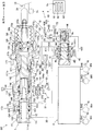
以下、本発明の実施形態について図に基づいて説明する。説明に用いる各図は概念図であり、各部の形状は必ずしも厳密なものではない場合がある。車両用制動装置BFは、図1に示すように、マスタシリンダ1と、反力発生装置2と、第1制御弁22と、第2制御弁23と、サーボ圧発生装置4と、アクチュエータ5と、ホイールシリンダ541~544と、ブレーキECU6と、各種センサ71~76と、を備えている。
マスタシリンダ1は、ブレーキペダル(「ブレーキ操作部材」に相当する)10の操作量に応じてブレーキ液をアクチュエータ5に供給する部位であり、メインシリンダ11、カバーシリンダ12、入力ピストン13、第1マスタピストン14、および第2マスタピストン15を備えている。ブレーキペダル10は、ドライバがブレーキ操作可能なブレーキ操作手段であれば良い。
メインシリンダ11は、前方が閉塞されて後方に開口する有底略円筒状のハウジングである。メインシリンダ11の内周側の後方寄りに、内向きフランジ状に突出する内壁部111が設けられている。内壁部111の中央は、前後方向に貫通する貫通孔111aとされている。また、メインシリンダ11の内部の内壁部111よりも前方に、内径がわずかに小さくなっている小径部位112(後方)、113(前方)が設けられている。つまり、小径部位112、113は、メインシリンダ11の内周面から内向き環状に突出している。メインシリンダ11の内部には、小径部位112に摺接して軸方向に移動可能に第1マスタピストン14が配設されている。同様に、小径部位113に摺接して軸方向に移動可能に第2マスタピストン15が配設されている。
カバーシリンダ12は、略円筒状のシリンダ部121、蛇腹筒状のブーツ122、およびカップ状の圧縮スプリング123で構成されている。シリンダ部121は、メインシリンダ11の後端側に配置され、メインシリンダ11の後側の開口に同軸的に嵌合されている。シリンダ部121の前方部位121aの内径は、内壁部111の貫通孔111aの内径よりも大きい。また、シリンダ部121の後方部位121bの内径は、前方部位121aの内径よりも小さい。
防塵用のブーツ122は蛇腹筒状で前後方向に伸縮可能であり、その前側でシリンダ部121の後端側開口に接するように組み付けられている。ブーツ122の後方の中央には貫通孔122aが形成されている。圧縮スプリング123は、ブーツ122の周りに配置されるコイル状の付勢部材であり、その前側がメインシリンダ11の後端に当接し、後側はブーツ122の貫通孔122aに近接するように縮径されている。ブーツ122の後端および圧縮スプリング123の後端は、操作ロッド10aに結合されている。圧縮スプリング123は、操作ロッド10aを後方に付勢している。
入力ピストン13は、ブレーキペダル10の操作に応じてカバーシリンダ12内を摺動するピストンである。入力ピストン13は、前方に底面を有し後方に開口を有する有底略円筒状のピストンである。入力ピストン13の底面を構成する底壁131は、入力ピストン13の他の部位よりも径が大きくなっている。入力ピストン13は、シリンダ部121の後方部位121bに軸方向に摺動可能かつ液密的に配置され、底壁131がシリンダ部121の前方部位121aの内周側に入り込んでいる。
入力ピストン13の内部には、ブレーキペダル10に連動する操作ロッド10aが配設されている。操作ロッド10aの先端のピボット10bは、入力ピストン13を前側に押動できるようになっている。操作ロッド10aの後端は、入力ピストン13の後側の開口およびブーツ122の貫通孔122aを通って外部に突出し、ブレーキペダル10に接続されている。ブレーキペダル10が踏み込み操作されたときに、操作ロッド10aは、ブーツ122および圧縮スプリング123を軸方向に押動しながら前進する。操作ロッド10aの前進に伴い、入力ピストン13も連動して前進する。
第1マスタピストン14は、メインシリンダ11の内壁部111に軸方向に摺動可能に配設されている。第1マスタピストン14は、前方側から順番に加圧筒部141、フランジ部142、および突出部143が一体となって形成されている。加圧筒部141は、前方に開口を有する有底略円筒状に形成され、メインシリンダ11の内周面との間に間隙を有し、小径部位112に摺接している。加圧筒部141の内部空間には、第2マスタピストン15との間にコイルばね状の付勢部材144が配設されている。付勢部材144により、第1マスタピストン14は後方に付勢されている。換言すると、第1マスタピストン14は、設定された初期位置に向けて付勢部材144により付勢されている。
フランジ部142は、加圧筒部141よりも大径で、メインシリンダ11の内周面に摺接している。突出部143は、フランジ部142よりも小径で、内壁部111の貫通孔111aに液密に摺動するように配置されている。突出部143の後端は、貫通孔111aを通り抜けてシリンダ部121の内部空間に突出し、シリンダ部121の内周面から離間している。突出部143の後端面は、入力ピストン13の底壁131から離間し、その離間距離は変化し得るように構成されている。
ここで、メインシリンダ11の内周面、第1マスタピストン14の加圧筒部141の前側、および第2マスタピストン15の後側により、「第1マスタ室1D」が区画されている。また、メインシリンダ11の内周面(内周部)と小径部位112と内壁部111の前面、および第1マスタピストン14の外周面により、第1マスタ室1Dよりも後方の後方室が区画されている。第1マスタピストン14のフランジ部142の前端部および後端部は後方室を前後に区分しており、前側に「第2液圧室1C」が区画され、後側に「サーボ室1A」が区画されている。第2液圧室1Cは、第1マスタピストン14の前進により容積が減少し第1マスタピストン14の後退により容積が増加する。また、メインシリンダ11の内周部、内壁部111の後面、シリンダ部121の前方部位121aの内周面(内周部)、第1マスタピストン14の突出部143(後端部)、および入力ピストン13の前端部により「第1液圧室1B」が区画されている。
第2マスタピストン15は、メインシリンダ11内の第1マスタピストン14の前方側に、小径部位113に摺接して軸方向に移動可能に配置されている。第2マスタピストン15は、前方に開口を有する筒状の加圧筒部151、および加圧筒部151の後側を閉塞する底壁152が一体となって形成されている。底壁152は、第1マスタピストン14との間に付勢部材144を支承している。加圧筒部151の内部空間には、メインシリンダ11の閉塞された内底面111dとの間に、コイルばね状の付勢部材153が配設されている。付勢部材153により、第2マスタピストン15は後方に付勢されている。換言すると、第2マスタピストン15は、設定された初期位置に向けて付勢部材153により付勢されている。メインシリンダ11の内周面、内底面111d、および第2マスタピストン15により、「第2マスタ室1E」が区画されている。
マスタシリンダ1には、内部と外部を連通させるポート11a~11iが形成されている。ポート11aは、メインシリンダ11のうち内壁部111よりも後方に形成されている。ポート11bは、ポート11aと軸方向の同様の位置に、ポート11aに対向して形成されている。ポート11aとポート11bは、メインシリンダ11の内周面とシリンダ部121の外周面との間の環状空間を介して連通している。ポート11aおよびポート11bは、配管161に接続され、かつリザーバ171(低圧源)に接続されている。
また、ポート11bは、シリンダ部121および入力ピストン13に形成された通路18により第1液圧室1Bに連通している。通路18は入力ピストン13が前進すると遮断され、これによって第1液圧室1Bとリザーバ171とが遮断される。ポート11cは、内壁部111より後方かつポート11aよりも前方に形成され、第1液圧室1Bと配管162とを連通させている。ポート11dは、ポート11cよりも前方に形成され、サーボ室1Aと配管163とを連通させている。ポート11eは、ポート11dよりも前方に形成され、第2液圧室1Cと配管164とを連通させている。
ポート11fは、小径部位112の両シール部材G1、G2の間に形成され、リザーバ172とメインシリンダ11の内部とを連通している。ポート11fは、第1マスタピストン14に形成された通路145を介して第1マスタ室1Dに連通している。通路145は、第1マスタピストン14が前進するとポート11fと第1マスタ室1Dが遮断される位置に形成されている。ポート11gは、ポート11fよりも前方に形成され、第1マスタ室1Dと管路31とを連通させている。
ポート11hは、小径部位113の両シール部材G3、G4の間に形成され、リザーバ173とメインシリンダ11の内部とを連通させている。ポート11hは、第2マスタピストン15の加圧筒部151に形成された通路154を介して第2マスタ室1Eに連通している。通路154は、第2マスタピストン15が前進するとポート11hと第2マスタ室1Eが遮断される位置に形成されている。ポート11iは、ポート11hよりも前方に形成され、第2マスタ室1Eと管路32とを連通させている。
また、マスタシリンダ1内には、適宜、Oリング等のシール部材が配置されている。シール部材G1、G2は、小径部位112に配置され、第1マスタピストン14の外周面に液密的に当接している。同様に、シール部材G3、G4は、小径部位113に配置され、第2マスタピストン15の外周面に液密的に当接している。また、入力ピストン13とシリンダ部121との間にもシール部材G5、G6が配置されている。
ストロークセンサ71は、ドライバの操作によるブレーキペダル10のストローク(操作量)を検出するセンサであり、検出信号をブレーキECU6に送信する。ブレーキスイッチ72は、ドライバによるブレーキペダル10の操作の有無を2値信号で検出するスイッチであり、検出信号をブレーキECU6に送信する。ブレーキスイッチ72は、ブレーキストップスイッチとも呼ばれる。
反力発生装置2は、ブレーキペダル10が操作されたときに操作力に対抗する反力を発生する装置であり、ストロークシミュレータ21を主にして構成されている。ストロークシミュレータ21は、ブレーキペダル10の操作に応じて第1液圧室1Bおよび第2液圧室1Cに反力圧を発生させる。ストロークシミュレータ21は、シリンダ211にピストン212が摺動可能に嵌合されて構成されている。ピストン212は圧縮スプリング213によって後方に付勢されており、ピストン212の後面側(配管164側)に反力室(「液圧室」に相当する)214が形成される。反力室214は、配管164およびポート11eを介して第2液圧室1Cに接続され、さらに、反力室214は、配管164を介して第1制御弁22および第2制御弁23に接続されている。
配管164の一部でありシリンダ211の入口付近に配置された分岐配管部164aには、オリフィス91が形成されている。圧力センサ73は、配管164のうち、オリフィス91よりも上流側(踏み込み時のブレーキ液の流れにおける上流側)の部分に配置されている。つまり、圧力センサ73は、配管164のうちオリフィス91よりもブレーキペダル10側の部分(上流側の部分)の液圧である反力圧を検出するセンサである。
このように、ストロークシミュレータ21は、ブレーキペダル10のストロークに応じて配管(「油路」に相当する)164を介してブレーキ液が供給される反力室214を区画するシリンダ211と、反力室214に供給されたブレーキ液によってシリンダ211内を摺動するピストン212と、配管164の一部である分岐配管部164aに設けられたオリフィス91と、配管164のうちオリフィス91よりも、反力室214に供給されるブレーキ液の供給方向上流側の部分の液圧(反力圧)を検出する圧力センサ73と、を有しているといえる。ストロークシミュレータ21は、反力圧に対応する反力をブレーキペダル10に付与する。
第1制御弁22は、非通電状態で閉じる構造の電磁弁であり、ブレーキECU6により開閉が制御される。第1制御弁22は、配管164と配管162との間に接続されている。ここで、配管164はポート11eを介して第2液圧室1Cに連通し、配管162はポート11cを介して第1液圧室1Bに連通している。また、第1制御弁22が開くと第1液圧室1Bが開放状態になり、第1制御弁22が閉じると第1液圧室1Bが密閉状態になる。したがって、配管164および配管162は、第1液圧室1Bと第2液圧室1Cとを連通するように設けられている。
第1制御弁22は通電されていない非通電状態で閉じており、このとき第1液圧室1Bと第2液圧室1Cとが遮断される。これにより、第1液圧室1Bが密閉状態になってブレーキ液の行き場がなくなり、入力ピストン13と第1マスタピストン14とが一定の離間距離を保って連動する。また、第1制御弁22は通電された通電状態では開いており、このとき第1液圧室1Bと第2液圧室1Cとが連通される。これにより、第1マスタピストン14の進退に伴う第1液圧室1Bおよび第2液圧室1Cの容積変化が、ブレーキ液の移動により吸収される。
圧力センサ73は、第2液圧室1Cおよび第1液圧室1Bの反力圧を検出するセンサであり、配管164に接続されている。圧力センサ73は、第1制御弁22が閉状態の場合には第2液圧室1Cの圧力を検出し、第1制御弁22が開状態の場合には連通された第1液圧室1Bの圧力も検出することになる。圧力センサ73は、検出信号をブレーキECU6に送信する。
第2制御弁23は、非通電状態で開く構造の電磁弁であり、ブレーキECU6により開閉が制御される。第2制御弁23は、配管164と配管161との間に接続されている。ここで、配管164はポート11eを介して第2液圧室1Cに連通し、配管161はポート11aを介してリザーバ171に連通している。したがって、第2制御弁23は、第2液圧室1Cとリザーバ171との間を非通電状態で連通して反力圧を発生させず、通電状態で遮断して反力圧を発生させる。
サーボ圧発生装置4は、いわゆる油圧式ブースタ(倍力装置)であって、減圧弁41、増圧弁42、圧力供給部43、およびレギュレータ44を備えている。減圧弁41は、非通電状態で開く常開型の電磁弁(常開弁)であり、ブレーキECU6により流量(又は圧力)が制御される。減圧弁41の一方は配管411を介して配管161に接続され、減圧弁41の他方は配管413に接続されている。つまり、減圧弁41の一方は、配管411、161、およびポート11a、11bを介してリザーバ171に連通している。減圧弁41は、閉弁することで、パイロット室4Dからブレーキ液が流出することを阻止する。なお、リザーバ171とリザーバ434とは、図示していないが連通している。リザーバ171とリザーバ434が同一のリザーバであっても良い。
増圧弁42は、非通電状態で閉じる常閉型の電磁弁(常閉弁)であり、ブレーキECU6により流量(又は圧力)が制御されている。増圧弁42の一方は配管421に接続され、増圧弁42の他方は配管422に接続されている。圧力供給部43は、レギュレータ44に主に高圧の作動液を供給する部位である。圧力供給部43は、アキュムレータ431、液圧ポンプ432、モータ433、およびリザーバ434を備えている。圧力センサ75は、アキュムレータ431の液圧を検出する。圧力供給部43は、の構成は公知であるため説明は省略する。
レギュレータ44は、機械式のレギュレータであって、内部にパイロット室4Dが形成されている。また、レギュレータ44には、複数のポート4a~4hが形成されている。パイロット室4Dは、ポート4f及び配管413を介して減圧弁41に接続され、ポート4g及び配管421を介して増圧弁42に接続されている。増圧弁42の開弁により、アキュムレータ431からポート4a、4b、4gを介して高圧のブレーキ液がパイロット室4Dに供給され、ピストンが移動し、パイロット室4Dが拡大する。当該拡大に応じて弁部材が移動し、ポート4aとポート4cが連通し、配管163を介して高圧のブレーキ液がサーボ室1Aに供給される。一方、減圧弁41の開弁により、パイロット室4Dの液圧(パイロット圧)が低下し、ポート4aとポート4cとの間の流路が弁部材により遮断される。このように、ブレーキECU6は、減圧弁41及び増圧弁42を制御することで、サーボ圧に対応するパイロット圧を制御し、サーボ圧を制御している。実際のサーボ圧は、圧力センサ74により検出される。本実施形態は、ブレーキ操作機構と調圧機構とが分離されたバイワイヤ構成になっている。
アクチュエータ5は、管路31、32を介して供給されるマスタ圧を調整してホイールシリンダ541~544に供給する装置である。アクチュエータ5は、ABSを構成するアクチュエータであって、図示しないが、複数の電磁弁、モータ、ポンプ、及びリザーバ等を備えている。アクチュエータ5は、ブレーキECU6の制御により、ホイールシリンダ541~544に対して増圧制御、保持制御、及び減圧制御を実行することができる。また、アクチュエータ5は、ブレーキECU6の制御により、アンチスキッド制御(ABS制御)などを実行することができる。また、各車輪Wには、車輪速度センサ76が設置されている。
(制動開始判定)
ブレーキECU6は、CPUやメモリを備える電子制御ユニットである。ブレーキECU6は、各センサ71~76、各制御弁22、23、サーボ圧発生装置4、及びアクチュエータ5と通信可能に接続されている(配線図示略)。ブレーキECU6は、機能として、制御部61と、制動開始判定部62と、を備えている。制御部61は、ストロークセンサ71及び圧力センサ73の検出値に基づいて目標減速度(目標サーボ圧)を演算し、演算結果に基づいて、各制御弁22、23、サーボ圧発生装置4、及びアクチュエータ5を制御する。
ブレーキECU6は、CPUやメモリを備える電子制御ユニットである。ブレーキECU6は、各センサ71~76、各制御弁22、23、サーボ圧発生装置4、及びアクチュエータ5と通信可能に接続されている(配線図示略)。ブレーキECU6は、機能として、制御部61と、制動開始判定部62と、を備えている。制御部61は、ストロークセンサ71及び圧力センサ73の検出値に基づいて目標減速度(目標サーボ圧)を演算し、演算結果に基づいて、各制御弁22、23、サーボ圧発生装置4、及びアクチュエータ5を制御する。
制動開始判定部62は、ブレーキペダル10の操作が開始されたか否かを判定するように構成されている。換言すると、制動開始判定部62は、制動制御を開始するか否かを判定する。制動開始判定部62は、制御部61が増圧制御を開始するタイミングを検出する部分ともいえる。制動開始判定部62が操作開始と判定すると、制御部61がブレーキ制御(液圧制御)を開始する。
具体的に、制動開始判定部62は、圧力センサ73で検出された反力圧が第1閾値以上となった後、次いでストロークセンサ71で検出されたストロークが第2閾値以上となった場合、ブレーキペダル10の操作が開始された(操作開始や制動制御開始といえる)と判定する。また、制動開始判定部62は、このストローク(値)として、フィルタ6aを介さないストロークセンサ71の検出値(生値)を用いるように構成されている。フィルタ6aは、ノイズを除去して滑らかに検出値を変化させるためのノイズフィルタである。この判定は、ドライバがブレーキペダル10を少しだけ素早く踏むような少量急操作時に有効となる。
本実施形態によれば、図2に示すように、少量急操作がなされた際、オリフィス91により反力圧の立ち上がりが早くなるため、ストロークが第2閾値以上となる前の時点で、反力圧が第1閾値以上となる。急なブレーキ操作により、ブレーキ液が急激に配管164に供給されるが、ストロークシミュレータ21のシリンダ211にブレーキ液が供給される前に、意図的に設けられた(又は構造的に生じる)オリフィス91により流路が狭められ、一時的にオリフィス91より上流側の部分が高圧となりやすい。本構成では、このオリフィス91による作用を判定に利用している。
また、ストロークセンサ71の生値はより実際のブレーキ操作に連動して変化するため、当該生値を判定要素として用いることで、ブレーキ操作に対する応答性を向上させることができる。フィルタ6aを介さない分、ノイズ等により数値自体の正確性は低減するが、操作開始(制動制御開始)は、当該生値に関する条件と反力圧に関する条件とのAND条件で判定されるため、判定の正確性(ロバスト性)は確保される。図2の制動判定及び目標減速度に示されるように、本実施形態によれば、少量急操作時であってもドライバの操作に対する応答性の高い制動制御を実現することができる。
さらに詳細に、制動開始判定部62には、上記判定方式を含む3種類の判定方式が設定されている。第1判定方式として、制動開始判定部62は、ストロークセンサ71から互いに異なる配線で送信された2つの検出値を、フィルタ6aを介した2つのフィルタ値で取得し、当該2つのフィルタ値が共に所定閾値以上となった場合に、操作開始と判定する。フィルタ値は、ノイズ等が除去されており正確性が高く、また2つのフィルタ値によるAND条件で判定するため、ロバスト性も確保される。この第1判定方式は、フィルタ値がブレーキ操作に追従しやすい通常のブレーキ操作時(比較的緩やかな操作時)に有効な判定方式である。
第2判定方式として、制動開始判定部62は、ブレーキスイッチ72がオンし(操作を検知し)、且つ反力圧が所定閾値以上となった場合に、操作開始と判定する。この第2判定方式は、ブレーキスイッチ72が反応良くオンする急ブレーキ時(急激に最後まで踏み込んで停車させようとする操作)に有効な判定方式である。
第3判定方式として、上記のように、反力圧と1つのストロークの生値とを判定要素としたものが設定されている。この第3判定方式は、上記のように少量急操作時に有効な判定方式である。これら3つの判定方式は、いずれも2つの判定要素(AND条件)により判定する方式である。制動開始判定部62は、これら3つの判定方式のいずれかでAND条件が満たされると、操作開始と判定する。このように、制動開始判定部62は、ストロークセンサ71の2つのフィルタ値、ストロークセンサ71の1つの生値、ブレーキスイッチ72の検出結果、及び圧力センサ73の検出値(反力圧)を監視し、これらの要素に基づいて操作開始を判定している。これにより、あらゆるブレーキ操作に対して応答性及び正確性を確保することができる。
本実施形態によれば、オリフィス91の影響を受ける反力圧を判定要素とすることで、例えばブレーキスイッチ72が反応しないような少量急操作時においても、制動開始判定の応答性を向上させることができる。また、反力圧とともに、ストロークも制動開始の判定要素とすることで、判定の正確性を確保することができる。このストロークの検出については、判定が反力圧とのAND条件で行われるため、正確性よりも応答性を優先させることができる。本実施形態では、ストロークの生値を用いることで応答性を優先させている。ブレーキ操作に直接的に連動するストロークの生値を用いることで、より応答性が向上する。なお、第2閾値を小さくするなどで応答性を優先させることもできる。
<その他の変形態様>
本発明は、上記実施形態に限られない。例えば、図3に示すように、車両用制動装置BFは、配管164のうちシリンダ211と圧力センサ73との間の部分に設けられる電磁弁92を備えても良い。この場合、ブレーキECU6は、電磁弁制御部63をさらに備える。電磁弁制御部63は、ブレーキペダル10の操作が開始されたと判定される蓋然性が高い場合、当該蓋然性が低い場合よりもストロークの増大量に対する反力圧の上昇量が大きくなるように電磁弁92を制御する。
本発明は、上記実施形態に限られない。例えば、図3に示すように、車両用制動装置BFは、配管164のうちシリンダ211と圧力センサ73との間の部分に設けられる電磁弁92を備えても良い。この場合、ブレーキECU6は、電磁弁制御部63をさらに備える。電磁弁制御部63は、ブレーキペダル10の操作が開始されたと判定される蓋然性が高い場合、当該蓋然性が低い場合よりもストロークの増大量に対する反力圧の上昇量が大きくなるように電磁弁92を制御する。
ブレーキペダル10の操作が開始されたと判定される蓋然性が高い場合とは、例えば車間距離が所定値未満である場合などである。つまり、レーダー等で検出された車間距離が所定値未満である場合に、上記蓋然性が高いと判定される。電磁弁制御部63は、上記蓋然性が高い場合に、電磁弁92の流路を絞り(閉弁側に制御し)、オリフィス効果を高めることで、ストローク増加に対する反力圧の上昇率を高める。これにより、上記蓋然性が高い場合に、より反力圧が立ち上がりやすくなり、制動開始判定の応答性を向上させることができる。この構成によれば、走行状況に応じて応答性を調整することができる。なお、電磁弁92は、オリフィス91に代えて(オリフィスとして)配管164に設けられても良い。
また、制動開始判定部62は、反力圧を発生させるブレーキ液の温度に相関する温度相関値が高いほど、第1閾値を小さくするように構成されても良い。例えば、配管164内のブレーキ液の温度が高くなると、ブレーキ液の粘度が低下するため、反力圧の立ち上がりが遅くなりやすい。したがって、ブレーキ液の温度相関値を温度センサ又は推定演算により取得し、その値に応じて第1閾値を変更することで、より確実に応答性を確保することができる。制動開始判定部62は、例えば、温度相関値が所定値以上となった場合に、第1閾値を小さくしても良い。
また、制動開始判定部62は、反力圧の変化勾配が第3閾値以上となった場合、反力圧及びストロークにかかわらず、ブレーキペダル10の操作が開始されたと判定するように構成されても良い。反力圧の変化勾配を、圧力センサ73の検出値を取得してから最初の数演算(例えば1、2演算)で算出し、その変化勾配を判定要素とすることで、反力圧が第1閾値以上となるよりも早く、操作開始を検出することができる。つまり、さらなる応答性の向上を図ることができる。例えば、この判定方式を第4判定方式として設定しても良い。
また、アクチュエータ5は、ホイールシリンダ541~544へのポンプ加圧が可能で、横滑り防止制御を実行できるタイプであっても良い。また、倍力機構は、サーボ圧発生装置4のような油圧式ブースタに限らず、例えば電動モータの制御によりボールねじを駆動させてマスタピストンを駆動させる電動式ブースタであっても良い。
Claims (6)
- ブレーキ操作部材のストロークに応じて油路を介してブレーキ液が供給される液圧室を区画するシリンダと、前記液圧室に供給されたブレーキ液によって前記シリンダ内を摺動するピストンと、前記油路に設けられたオリフィスと、前記油路のうち前記オリフィスよりも前記液圧室に供給されるブレーキ液の供給方向上流側の部分の液圧である反力圧を検出する圧力センサと、を有するストロークシミュレータを備え、前記ストロークシミュレータにより前記反力圧に対応する反力が前記ブレーキ操作部材に付与される車両用制動装置であって、
前記ストロークを検出するストロークセンサと、
前記圧力センサで検出された前記反力圧が第1閾値以上となり、且つ前記ストロークセンサで検出された前記ストロークが第2閾値以上となった場合、前記ブレーキ操作部材の操作が開始されたと判定する制動開始判定部と、
を備える車両用制動装置。 - 前記制動開始判定部は、前記反力圧が前記第1閾値以上となった後、次いで前記ストロークが第2閾値以上となった場合、前記ブレーキ操作部材の操作が開始されたと判定する請求項1に記載の車両用制動装置。
- 前記制動開始判定部は、前記ストロークとして、フィルタを介さない前記ストロークセンサの検出値を用いる請求項1又は2に記載の車両用制動装置。
- 前記油路のうち前記シリンダと前記圧力センサとの間の部分に設けられる電磁弁又は前記オリフィスに代えて前記油路に設けられる電磁弁と、
前記ブレーキ操作部材の操作が開始されたと判定される蓋然性が高い場合、前記蓋然性が低い場合よりも前記ストロークの増大量に対する前記反力圧の上昇量が大きくなるように前記電磁弁を制御する電磁弁制御部と、
を備える請求項1~3の何れか一項に記載の車両用制動装置。 - 前記制動開始判定部は、前記反力圧を発生させるブレーキ液の温度に相関する温度相関値が高いほど、前記第1閾値を小さくする請求項1~4の何れか一項に記載の車両用制動装置。
- 前記制動開始判定部は、前記反力圧の変化勾配が第3閾値以上となった場合、前記反力圧及び前記ストロークにかかわらず、前記ブレーキ操作部材の操作が開始されたと判定する請求項1~5の何れか一項に記載の車両用制動装置。
Priority Applications (3)
| Application Number | Priority Date | Filing Date | Title |
|---|---|---|---|
| CN201880071197.4A CN111315621B (zh) | 2017-11-06 | 2018-11-06 | 车辆用制动装置 |
| US16/759,381 US11827199B2 (en) | 2017-11-06 | 2018-11-06 | Vehicle brake device |
| DE112018005267.2T DE112018005267T5 (de) | 2017-11-06 | 2018-11-06 | Fahrzeugbremsvorrichtung |
Applications Claiming Priority (2)
| Application Number | Priority Date | Filing Date | Title |
|---|---|---|---|
| JP2017-213856 | 2017-11-06 | ||
| JP2017213856A JP6972936B2 (ja) | 2017-11-06 | 2017-11-06 | 車両用制動装置 |
Publications (1)
| Publication Number | Publication Date |
|---|---|
| WO2019088296A1 true WO2019088296A1 (ja) | 2019-05-09 |
Family
ID=66332039
Family Applications (1)
| Application Number | Title | Priority Date | Filing Date |
|---|---|---|---|
| PCT/JP2018/041113 Ceased WO2019088296A1 (ja) | 2017-11-06 | 2018-11-06 | 車両用制動装置 |
Country Status (5)
| Country | Link |
|---|---|
| US (1) | US11827199B2 (ja) |
| JP (1) | JP6972936B2 (ja) |
| CN (1) | CN111315621B (ja) |
| DE (1) | DE112018005267T5 (ja) |
| WO (1) | WO2019088296A1 (ja) |
Cited By (1)
| Publication number | Priority date | Publication date | Assignee | Title |
|---|---|---|---|---|
| WO2021239619A1 (de) * | 2020-05-29 | 2021-12-02 | Bayerische Motoren Werke Aktiengesellschaft | Vorrichtung und verfahren zur steuerung eines bremssystems, bremssystem und fahrzeug |
Families Citing this family (3)
| Publication number | Priority date | Publication date | Assignee | Title |
|---|---|---|---|---|
| JP7021592B2 (ja) * | 2018-03-30 | 2022-02-17 | 株式会社アドヴィックス | 制動制御装置 |
| JP7484154B2 (ja) | 2019-12-13 | 2024-05-16 | 株式会社デンソー | 車両用ブレーキシステム |
| US12208777B2 (en) | 2021-05-24 | 2025-01-28 | Bwi (Shanghai) Co., Ltd. | Brake-by-wire system with pressure balanced PSU piston |
Citations (3)
| Publication number | Priority date | Publication date | Assignee | Title |
|---|---|---|---|---|
| JP2000335402A (ja) * | 1999-05-31 | 2000-12-05 | Mitsubishi Motors Corp | ブレーキ制御装置 |
| JP2004136731A (ja) * | 2002-10-16 | 2004-05-13 | Nissan Motor Co Ltd | 車両の制動制御装置 |
| JP2004142654A (ja) * | 2002-10-25 | 2004-05-20 | Honda Motor Co Ltd | 車両用ブレーキ装置 |
Family Cites Families (26)
| Publication number | Priority date | Publication date | Assignee | Title |
|---|---|---|---|---|
| FR2818944B1 (fr) * | 2001-01-02 | 2003-06-27 | Bosch Gmbh Robert | Installation de freinage hydraulique pour vehicule comportant un simulateur actif |
| JP4729984B2 (ja) * | 2004-12-22 | 2011-07-20 | 日産自動車株式会社 | 車両用制動力制御方法、及び車両用制動力制御装置 |
| WO2008066892A1 (en) * | 2006-11-30 | 2008-06-05 | Kelsey-Hayes Company | Method and device for sensor signal noise reduction |
| JP4787222B2 (ja) * | 2007-09-25 | 2011-10-05 | 本田技研工業株式会社 | ブレーキシステム |
| BR112013009090A2 (ja) * | 2010-10-13 | 2018-05-02 | Toyota Jidosha Kabushiki Kaisha | Brake mechanism for vehicles, and a control device |
| DE102011081240A1 (de) * | 2010-10-13 | 2012-04-19 | Continental Teves Ag & Co. Ohg | Verfahren zur Überwachung einer Bremsanlage sowie Bremsanlage |
| JP5724550B2 (ja) * | 2011-03-31 | 2015-05-27 | 株式会社アドヴィックス | 車両用制動装置 |
| WO2013042620A1 (ja) * | 2011-09-20 | 2013-03-28 | 日産自動車株式会社 | 車両のブレーキ制御装置 |
| US9321438B2 (en) * | 2012-06-04 | 2016-04-26 | Hino Motors, Ltd. | Automatic braking control device |
| KR101448751B1 (ko) * | 2012-12-13 | 2014-10-13 | 현대자동차 주식회사 | 차량 제동 시스템 및 그 제어 방법 |
| DE102013216141A1 (de) * | 2013-08-14 | 2015-02-19 | Continental Teves Ag & Co. Ohg | Bremsanlage für Kraftfahrzeuge |
| US9061671B2 (en) * | 2013-08-27 | 2015-06-23 | Bendix Commercial Vehicle Systems Llc | Driver braking demand indicator apparatus for a heavy vehicle |
| JP6287244B2 (ja) | 2014-01-20 | 2018-03-07 | トヨタ自動車株式会社 | 車両の制動制御装置 |
| JP6341580B2 (ja) * | 2014-04-24 | 2018-06-13 | 日立オートモティブシステムズ株式会社 | ブレーキ制御装置、ブレーキシステム、及びブレーキ液圧発生方法 |
| JP6124840B2 (ja) * | 2014-05-26 | 2017-05-10 | 株式会社アドヴィックス | 制動制御装置 |
| DE102014210550A1 (de) * | 2014-06-04 | 2015-12-17 | Robert Bosch Gmbh | Sensorvorrichtung für ein mit einem elektromechanischen Bremskraftverstärker ausgestattetes Bremssystem und Verfahren zum Ermitteln einer Bremswunschvorgabe an ein mit einem elektromechanischen Bremskraftverstärker ausgestattetes Bremssystem |
| US9463873B2 (en) * | 2014-07-13 | 2016-10-11 | The Boeing Company | Vehicle braking system having braking control and skid reduction functions |
| JP6250892B2 (ja) * | 2015-01-30 | 2017-12-20 | 株式会社アドヴィックス | 車両用制動装置 |
| JP6138182B2 (ja) * | 2015-02-20 | 2017-05-31 | 株式会社アドヴィックス | 車両用制動装置 |
| JP2017171015A (ja) * | 2016-03-22 | 2017-09-28 | トヨタ自動車株式会社 | 液圧ブレーキシステムおよびブレーキ操作装置 |
| DE102016207581B4 (de) * | 2016-05-03 | 2021-07-15 | Ford Global Technologies, Llc | Verfahren zum Betreiben eines Bremsassistenzsystems eines Fahrzeugs |
| KR102577622B1 (ko) * | 2016-10-11 | 2023-09-12 | 에이치엘만도 주식회사 | 전자식 브레이크 시스템 및 그 제어 방법 |
| US10046749B2 (en) * | 2016-12-08 | 2018-08-14 | Robert Bosch Gmbh | Brake system and method of operating |
| US10144404B2 (en) * | 2016-12-08 | 2018-12-04 | Robert Bosch Gmbh | Vehicle having brake system and method of operating |
| DE102018122664A1 (de) * | 2018-09-17 | 2020-03-19 | Wabco Gmbh | Verfahren zum Ermitteln von Sprüngen und/oder Knickpunkten in einer Betätigungscharakteristik einer Betätigungseinheit, Auswertemodul und Fahrzeug |
| KR102795969B1 (ko) * | 2019-12-16 | 2025-04-14 | 현대자동차주식회사 | Flex brake의 제동 이질감 보상 제어 시스템 |
-
2017
- 2017-11-06 JP JP2017213856A patent/JP6972936B2/ja active Active
-
2018
- 2018-11-06 DE DE112018005267.2T patent/DE112018005267T5/de active Pending
- 2018-11-06 WO PCT/JP2018/041113 patent/WO2019088296A1/ja not_active Ceased
- 2018-11-06 US US16/759,381 patent/US11827199B2/en active Active
- 2018-11-06 CN CN201880071197.4A patent/CN111315621B/zh active Active
Patent Citations (3)
| Publication number | Priority date | Publication date | Assignee | Title |
|---|---|---|---|---|
| JP2000335402A (ja) * | 1999-05-31 | 2000-12-05 | Mitsubishi Motors Corp | ブレーキ制御装置 |
| JP2004136731A (ja) * | 2002-10-16 | 2004-05-13 | Nissan Motor Co Ltd | 車両の制動制御装置 |
| JP2004142654A (ja) * | 2002-10-25 | 2004-05-20 | Honda Motor Co Ltd | 車両用ブレーキ装置 |
Cited By (2)
| Publication number | Priority date | Publication date | Assignee | Title |
|---|---|---|---|---|
| WO2021239619A1 (de) * | 2020-05-29 | 2021-12-02 | Bayerische Motoren Werke Aktiengesellschaft | Vorrichtung und verfahren zur steuerung eines bremssystems, bremssystem und fahrzeug |
| US12325391B2 (en) | 2020-05-29 | 2025-06-10 | Bayerische Motoren Werke Aktiengesellschaft | Device and method for controlling a braking system, braking system and vehicle |
Also Published As
| Publication number | Publication date |
|---|---|
| US11827199B2 (en) | 2023-11-28 |
| US20200290576A1 (en) | 2020-09-17 |
| DE112018005267T5 (de) | 2020-06-25 |
| CN111315621B (zh) | 2022-07-15 |
| JP2019084921A (ja) | 2019-06-06 |
| JP6972936B2 (ja) | 2021-11-24 |
| CN111315621A (zh) | 2020-06-19 |
Similar Documents
| Publication | Publication Date | Title |
|---|---|---|
| US9499149B2 (en) | Brake hydraulic pressure generator | |
| JP5989022B2 (ja) | 車両用制動装置 | |
| JP6025762B2 (ja) | 車両制御装置 | |
| US10793125B2 (en) | Vehicle braking device | |
| CN111315621B (zh) | 车辆用制动装置 | |
| JP6988417B2 (ja) | 車両用制動装置 | |
| JP6250892B2 (ja) | 車両用制動装置 | |
| JP7218570B2 (ja) | 制動制御装置 | |
| JP6371270B2 (ja) | 車両用制動装置 | |
| JP6193791B2 (ja) | 車両用制動装置 | |
| WO2016175114A1 (ja) | 車両用制動装置 | |
| US11155254B2 (en) | Braking device for vehicle | |
| US11738727B2 (en) | Brake control device | |
| US20200130655A1 (en) | Vehicle braking device | |
| JP6241207B2 (ja) | 制動制御装置 | |
| JP6973065B2 (ja) | 車両用制動装置 | |
| JP7021592B2 (ja) | 制動制御装置 | |
| JP2019098898A (ja) | 車両用制動装置 |
Legal Events
| Date | Code | Title | Description |
|---|---|---|---|
| 121 | Ep: the epo has been informed by wipo that ep was designated in this application |
Ref document number: 18874330 Country of ref document: EP Kind code of ref document: A1 |
|
| 122 | Ep: pct application non-entry in european phase |
Ref document number: 18874330 Country of ref document: EP Kind code of ref document: A1 |