WO2019087887A1 - 画像形成装置 - Google Patents
画像形成装置 Download PDFInfo
- Publication number
- WO2019087887A1 WO2019087887A1 PCT/JP2018/039440 JP2018039440W WO2019087887A1 WO 2019087887 A1 WO2019087887 A1 WO 2019087887A1 JP 2018039440 W JP2018039440 W JP 2018039440W WO 2019087887 A1 WO2019087887 A1 WO 2019087887A1
- Authority
- WO
- WIPO (PCT)
- Prior art keywords
- liquid
- toner
- liquid developer
- carrier
- separation
- Prior art date
Links
Images


Classifications
-
- G—PHYSICS
- G03—PHOTOGRAPHY; CINEMATOGRAPHY; ANALOGOUS TECHNIQUES USING WAVES OTHER THAN OPTICAL WAVES; ELECTROGRAPHY; HOLOGRAPHY
- G03G—ELECTROGRAPHY; ELECTROPHOTOGRAPHY; MAGNETOGRAPHY
- G03G15/00—Apparatus for electrographic processes using a charge pattern
- G03G15/06—Apparatus for electrographic processes using a charge pattern for developing
- G03G15/10—Apparatus for electrographic processes using a charge pattern for developing using a liquid developer
-
- G—PHYSICS
- G03—PHOTOGRAPHY; CINEMATOGRAPHY; ANALOGOUS TECHNIQUES USING WAVES OTHER THAN OPTICAL WAVES; ELECTROGRAPHY; HOLOGRAPHY
- G03G—ELECTROGRAPHY; ELECTROPHOTOGRAPHY; MAGNETOGRAPHY
- G03G15/00—Apparatus for electrographic processes using a charge pattern
- G03G15/14—Apparatus for electrographic processes using a charge pattern for transferring a pattern to a second base
- G03G15/16—Apparatus for electrographic processes using a charge pattern for transferring a pattern to a second base of a toner pattern, e.g. a powder pattern, e.g. magnetic transfer
-
- G—PHYSICS
- G03—PHOTOGRAPHY; CINEMATOGRAPHY; ANALOGOUS TECHNIQUES USING WAVES OTHER THAN OPTICAL WAVES; ELECTROGRAPHY; HOLOGRAPHY
- G03G—ELECTROGRAPHY; ELECTROPHOTOGRAPHY; MAGNETOGRAPHY
- G03G21/00—Arrangements not provided for by groups G03G13/00 - G03G19/00, e.g. cleaning, elimination of residual charge
Definitions
- the present invention relates to an electrophotographic image forming apparatus that forms an image using a liquid developer.
- an image forming apparatus that forms an image using a liquid developer containing toner and a carrier liquid is known.
- a liquid developer not used in an image forming process is collected from a photosensitive drum, an intermediate transfer roller or the like and reused.
- a liquid developer collected from a photosensitive drum, an intermediate transfer roller, a transfer roller, etc. after transfer of a toner image is conveyed to a separation device, and the toner and carrier liquid in the liquid developer are separated by the separation device and separated.
- a process of recycling the carrier liquid is carried out (Patent Document 1).
- the present invention has been made in view of the above-described problems, and an object of the present invention is to provide an image forming apparatus capable of reducing the contamination of foreign matter into the carrier liquid to be reused even when the carrier liquid is reused.
- the image forming apparatus comprises a photosensitive body, a developing device for developing an electrostatic latent image formed on the photosensitive body into a toner image with a liquid developer composed of toner and carrier liquid, and toner from the photosensitive body
- An intermediate transfer member to which an image is primarily transferred a transfer member to secondarily transfer a toner image primarily transferred to the intermediate transfer member to a recording material, and a photosensitive member to recover a liquid developer remaining on the photosensitive member after primary transfer
- a separation transport path connecting the photoreceptor cleaning portion and the separation device so as to transport the liquid developer collected by the photoreceptor cleaning portion to the separation device, and collecting by the transfer member cleaning portion Liquid developer The possible transport to the container without passing through the separation device, and a recovery conveyance path for connecting the storage
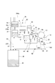
- FIG. 1 is a schematic configuration view showing an image forming apparatus of the present embodiment.
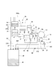
- FIG. 2 is a schematic view showing a transport path of the liquid developer in the image forming apparatus of the first embodiment.
- the external appearance perspective view which shows a isolation
- the perspective view which cuts and shows a part of isolation
- Sectional drawing which shows a part of isolation
- the enlarged view which expands and shows the A section of FIG. 6 is a graph showing the relationship between the total number of image formations and the accumulated amount of paper dust in the liquid developer in the image forming apparatus of the present embodiment.
- FIG. 7 is a schematic view showing a transport path of the liquid developer in the image forming apparatus of the second embodiment.
- 8 is a graph showing the relationship between the total number of image formations and the accumulated amount of paper dust in the liquid developer in the conventional image forming apparatus.
- 6 is a graph showing the relationship between the paper powder content in the liquid developer and the difference in gloss when the paper powder is mixed with the carrier liquid.
- the graph which shows the relationship between the paper dust content in a liquid developer of ultraviolet curing type, and the exposure energy required to harden a carrier liquid, when paper dust is mixed with a carrier liquid.
- 7 is a graph showing the relationship between the total number of images formed and the accumulated amount of paper dust in the liquid developer in a conventional image forming apparatus using a UV curable liquid developer.
- An image forming apparatus 100 illustrated in FIG. 1 is an electrophotographic digital printer that forms a toner image on a recording material S (a sheet, a sheet material such as an OHP sheet, etc.).
- the image forming apparatus 100 operates based on an image signal, transfers the toner image formed by the image forming unit 12 to the recording material S sequentially conveyed from the cassettes 11a and 11b, and then obtains an image by fixing. ing.
- the image signal is sent to the image forming apparatus 100 from an external terminal such as a scanner or a personal computer (not shown).
- the image forming unit 12 includes a photosensitive drum 13 as a photosensitive member, a charger 14, a laser exposure device 15, a developing device 16, and a drum cleaner 19.
- the laser light E is irradiated from the laser exposure device 15 according to the image signal onto the photosensitive drum 13 whose surface is charged by the charger 14, and an electrostatic latent image is formed on the photosensitive drum 13.
- the electrostatic latent image is developed by the developing device 16 as a toner image.
- the liquid developer D in which the powder toner as the dispersoid is dispersed in the carrier liquid as the dispersion medium is contained in the developing device 16 as the developing device. Develop using.
- the liquid developer D is generated by mixing and dispersing the toner T in the carrier liquid C at a predetermined ratio in the mixer 31 as a mixer, and is supplied to the developing device 16.
- the carrier liquid C for replenishment is accommodated in a carrier tank 32 as a carrier container, and the toner T for replenishment is accommodated in a toner tank 33 as a toner container. Then, according to the mixed state of the carrier liquid C and the toner T in the mixer 31, the carrier liquid C or the toner T is supplied to the mixer 31 from each tank.
- the mixer 31 contains a stirring blade driven by a motor (not shown), and mixes the supplied carrier liquid and the toner T by stirring to disperse the toner in the carrier liquid.
- the volume of the mixer 31 is about 2000 g in terms of the weight of the developer.
- the liquid developer D supplied from the mixer 31 to the developing device 16 is coated (supplied) on the developing roller 18 by the coating roller 17 in the supply section 16 a of the developing device 16 and used for development.
- the developing roller 18 carries and conveys a liquid developer on the surface, and develops the electrostatic latent image formed on the photosensitive drum 13 with toner.
- the carrier liquid C and the toner T remaining on the developing roller 18 after development are collected in the collection section 16 b of the developing device 16.
- the coating of the liquid developer D from the coating roller 17 to the developing roller 18 and the development from the developing roller 18 to the electrostatic latent image on the photosensitive drum 13 are performed using an electric field.
- the toner image formed on the photosensitive drum 13 is primarily transferred to the intermediate transfer roller 20 using an electric field, and conveyed to the nip portion (secondary transfer portion) formed by the intermediate transfer roller 20 and the transfer roller 21. .
- the liquid developer (toner T and carrier liquid C) remaining on the photosensitive drum 13 (on the photosensitive member) after the primary transfer to the intermediate transfer roller 20 is collected by the drum cleaner 19.
- the drum cleaner 19 as a photosensitive member cleaning portion is made of, for example, a blade-like member made of rubber, and is in contact with the photosensitive drum 13 with a linear pressure of 30 (g / cm). At least one of the intermediate transfer roller 20 and the transfer roller 21 may be an endless belt.
- the recording material S accommodated in the cassettes 11a and 11b is conveyed toward the resist conveyance unit 23 by the feeding units 22a and 22b configured by conveyance rollers and the like.
- the resist conveyance unit 23 conveys the recording material S to the nip portion between the intermediate transfer roller 20 and the transfer roller 21 in accordance with the timing of the toner image transferred to the intermediate transfer roller 20.
- the toner image is secondarily transferred onto the passing recording material S, and the recording material S onto which the toner image has been transferred is conveyed by the conveyance belt 24 to the fixing device 25.
- the toner image transferred to the recording material S is fixed.
- the recording material S on which the toner image is fixed is discharged to the outside of the machine, and the image process is completed.
- the fixing device 25 employs a heat fixing method. In this system, the fixing device 25 has two rollers for sandwiching the recording material S from above and below and pressing them against each other, and the two rollers maintain their surface temperature at about 200.degree.
- the surface of the recording material S conveyed at a predetermined process speed (for example, 600 mm / s) is maintained at a temperature of 60 ° C. or higher, which is the glass transition point at which the toner melts.
- the toner melts, the toner is fixed on the recording material S.
- the fixing device 25 irradiates ultraviolet light (UV light) to cure the liquid developer.
- UV light ultraviolet light
- An intermediate transfer roller cleaner 26 and a transfer roller cleaner 27 as a transfer member cleaning unit are respectively provided on the intermediate transfer roller 20 as an intermediate transfer member and the transfer roller 21 as a transfer member.
- the intermediate transfer roller cleaner 26 recovers the liquid developer (toner T and carrier liquid C) remaining on the intermediate transfer roller 20 after secondary transfer from the intermediate transfer roller 20.
- the transfer roller cleaner 27 recovers the liquid developer (toner T and carrier liquid C) remaining on the transfer roller 21 after the secondary transfer from the transfer roller 21.
- each of the intermediate transfer roller cleaner 26 and the transfer roller cleaner 27 is formed of a blade-like member made of rubber, and is applied to the intermediate transfer roller 20 and the transfer roller 21 with a linear pressure of 30 (g / cm). Be touched.
- the method of collecting the liquid developer (mainly toner T) remaining on the intermediate transfer roller 20 and the transfer roller 21 is not limited to this.
- the toner T may be separated by an electric field by bringing a roller-like member into contact with the intermediate transfer roller 20 (on the intermediate transfer member) and the transfer roller 21 (on the transfer member).
- liquid developer D As the liquid developer D used in the image forming apparatus 100 of the present embodiment, a liquid developer conventionally used may be used, but an ultraviolet-curable liquid developer D may be used. Therefore, the ultraviolet curable liquid developer D will be described.
- the liquid developer D is a UV curable liquid developer containing a cationically polymerizable liquid monomer, a photopolymerization initiator, and toner particles insoluble in the cationically polymerizable liquid monomer.
- the cationically polymerizable liquid monomer is a vinyl ether compound
- the photopolymerization initiator is a compound represented by the following general formula (1).
- the toner particles include a coloring material that emits a color in a toner resin.
- other materials such as a charge control agent may be contained.
- known techniques such as core shelving in which a coloring material is dispersed, polymerizing and encapsulating resin gradually, melting of resin and the like, and incorporating coloring material in resin may be used. Good.
- the toner resin epoxy, styrene acrylic, etc. are used.
- the colorant that emits a color may be a general organic-inorganic pigment.
- a dispersant is used to improve toner dispersibility in production, a synergist is also possible.
- the curable liquid which is a carrier liquid, is composed of a charge control agent that gives the charge on the toner surface, a photopolymerization agent that generates an acid upon irradiation with ultraviolet light (UV), and a monomer that bonds with the acid.
- the monomer is a vinyl ether compound that polymerizes by a cationic polymerization reaction.
- a sensitizer may be contained. The photopolymerization may reduce the storage stability, so 10 to 5000 ppm of a cationic polymerization inhibitor may be added.
- charge control aids, other additives, etc. may be used.
- the UV curing agent (monomer) of this developer comprises about 90% (by weight) of a monofunctional monomer (formula 2) having one vinyl ether group and a bifunctional monomer (formula 3) having two vinyl ether groups. % Mixed.
- a photoinitiator 0.1% of what is represented by following (Formula 4) is mixed.
- a high resistance liquid developer can be obtained unlike the case where an ionic photoacid generator is used, while achieving good fixation.
- the cationically polymerizable liquid monomer is dicyclopentadiene vinyl ether, cyclohexane dimethanol divinyl ether, tricyclodecane vinyl ether, trimethylolpropane trivinyl ether, 2-ethyl-1,3-hexanediol divinyl ether, 2,4-diethyl- 1,5-Pentanediol divinyl ether, 2-butyl-2-ethyl-1,3-propanediol divinyl ether, neopentyl glycol divinyl ether, pentaerythritol tetravinyl ether and 1,2-decanediol divinyl ether It is desirable that the compound be
- charge control agent known ones can be used.
- Specific compounds include oils and fats such as linseed oil and soybean oil; alkyd resins, halogen polymers, aromatic polycarboxylic acids, acid group-containing water-soluble dyes, oxidation condensates of aromatic polyamines, cobalt naphthenate, naphthenic acid
- Metallic soaps such as nickel, iron naphthenate, zinc naphthenate, cobalt octylate, nickel octylate, zinc octylate, cobalt dodecylate, nickel dodecylate, zinc dodecylate, aluminum stearate, cobalt 2-ethylhexanoate;
- the liquid developer collected by the intermediate transfer roller cleaner 26 is stored as a waste liquid W in a waste liquid storage container 35 as a storage container. Further, in the present embodiment, the liquid developer collected by the transfer roller cleaner 27 is held as it is by the transfer roller cleaner 27 because the amount thereof is small. However, as in the second embodiment described later (see FIG. 8), the liquid developer collected by the transfer roller cleaner 27 may be stored in the waste liquid storage container 35 as the waste liquid W.
- the waste liquid storage container 35 may be provided exchangeably with respect to the apparatus main body 100 a (see FIG. 1) of the image forming apparatus 100. In that case, it is preferable that the user can be notified of the replacement of the waste liquid storage container 35 when the waste liquid W stored in the waste liquid storage container 35 exceeds a predetermined amount.
- the first separation and extraction device 37 as a separation device, which will be described in detail later, separates the carrier liquid and the waste liquid W that may contain foreign substances such as toner and paper powder when the carrier liquid and the toner are separated.
- the separated waste liquid W is collected in the waste liquid storage container 35.
- the second separation and extraction device 34 separates unnecessary components in the carrier liquid other than toner from the carrier liquid separated and extracted by the first separation and extraction device 37, which will be described in detail later.
- a substance with a low volume resistivity (low resistance carrier) contained in the carrier liquid can be mentioned.
- the substance forming the carrier liquid contains the charge control agent, and the component of the low resistance carrier is mainly the charge control agent.
- the volume resistivity of the charge control agent is, by way of example, 1.0E + 9 ⁇ cm.
- the volume resistivity of the carrier liquid which does not contain a charge control agent is 1.0E + 12 ohm-cm.
- the transportation of the liquid developer D will be described more specifically.
- the transport pipes from the carrier tank 32 and the toner tank 33 to the mixer 31 are provided with solenoid valves 41 and 42, respectively.
- the solenoid valves 41 and 42 adjust the supply amounts of the carrier liquid C and the toner T to the mixer 31.
- a liquid developer D necessary for development is supplied to the developing device 16 using a pump 44 as a liquid developer supply unit.
- the liquid developer collected in the collection section 16 b of the developing device 16 is returned to the mixer 31 by the pump 43. This is because the liquid developer collected in the collection section 16b is not used for development or the like and is hardly deteriorated.
- the drum cleaner 19 and the first separation and extraction device 37 are connected to each other by a drum recovery liquid transport pipe 190 as a separation transport path.
- the drum cleaner 19 and the first separation and extraction device 37 are connected by the drum collection liquid transfer pipe 190, so that the liquid developer collected by the drum cleaner 19 can be transported to the first separation and extraction device 37.
- the liquid developer collected by the drum cleaner 19 is conveyed to the first separation and extraction device 37 by a pump 48 provided in the middle of the drum collected liquid transport pipe 190.
- the carrier liquid (liquid developer) separated and extracted by the first separation and extraction device 37 is conveyed to the second separation and extraction device 34 by the solenoid valve 51.
- the intermediate transfer roller cleaner 26 and the waste liquid storage container 35 are connected to each other by a medium recovery liquid transport pipe 260. Since the intermediate transfer roller cleaner 26 and the waste liquid storage container 35 are connected by the medium recovery liquid transport pipe 260, the liquid developer collected by the intermediate transfer roller cleaner 26 can be transported to the waste liquid storage container 35. .
- the liquid developer collected by the intermediate transfer roller cleaner 26 is a small amount compared to the liquid developer collected by the drum cleaner 19, and the toner concentration (the ratio of the weight of the toner to the total weight of the toner and the carrier liquid: TD) Also called ratio) and viscosity are relatively high.
- the liquid developer collected by the intermediate transfer roller cleaner 26 is transported to the waste liquid storage container 35 by a screw (not shown) or the like provided in the middle recovery liquid transport pipe 260.
- a pump (not shown) may be provided in the middle of the middle recovery liquid transport pipe 260 to be able to be transported by this pump.
- the carrier liquid separated by the first separation and extraction device 37 and the second separation and extraction device 34 is reusable, and is transported to the carrier tank 32 by the solenoid valve 45 as a carrier supply unit for reuse.
- the waste liquid W mainly toner
- the waste liquid W is transported to the waste liquid storage container 35 by the solenoid valve 47 provided in the waste liquid transport pipe 370 as a discharge conveyance path. Be done.
- it is difficult to reuse the waste liquid W (mainly low resistance carrier) separated by the second separation and extraction device 34 it is provided in a transport pipe connecting the second separation and extraction device 34 and the waste liquid storage container 35. It is transported to the waste liquid storage container 35 by the solenoid valve 52.
- the first separation and extraction device 37 is a device that separates the liquid developer into toner and carrier liquid using an electric field, and separately extracts the carrier liquid and the toner.
- the second separation and extraction apparatus 34 is an apparatus for separating and extracting a low resistance carrier (mainly a charge control agent) from the carrier liquid separated and extracted by the first separation and extraction apparatus 37 using an electric field.
- the first separation and extraction device 37 and the second separation and extraction device 34 may have the same configuration. Therefore, in the following, the second separation and extraction device 34 will be described with reference to FIGS. 3 to 6, and the same configuration of the first separation and extraction device 37 is attached with reference numerals in parentheses for the same configuration. Explain to.
- the reason for providing the second separation and extraction device 34 will be described.
- a substance with a low volume resistivity low resistance carrier
- the resistance of the entire liquid developer decreases, which may cause image defects.
- a high density image such as a solid image (a toner image formed on the entire surface of an image formable area of the photosensitive drum and having an image ratio (printing rate) of 100%)
- the output image In particular, the resistance is apt to decrease because the ratio of the carrier liquid to the liquid is small.
- the second separation and extraction device 34 is provided to suppress such a decrease in the volume resistivity of the carrier liquid.
- the carrier liquid (liquid developer) separated by the first separation and extraction device 37 is transported into the liquid storage container 346 from the inlet 34 b of the second separation and extraction device 34 as shown by the arrows in FIGS. 3 and 4. . Then, it is supplied to the buffer container 348 (see FIG. 4) in the liquid storage container 346.
- the buffer container 348 is provided in the second separation and extraction device 34, but may be provided alone.
- the carrier liquid supplied to the buffer container 348 is transported by the pump 34c and passes through the filter 34d.
- the carrier liquid having passed through the filter 34d is introduced into the supply tray 346a as shown in FIG.
- the filter 34d may be omitted, and the carrier liquid separated and extracted by the first separation and extraction device 37 may be directly introduced into the supply tray 346a.
- the carrier liquid introduced into the supply tray 346 a is divided into a low resistance carrier (mainly a charge control agent) and a high resistance carrier in the second separation and extraction device 34. Then, the extracted low resistance carrier is sent to the waste liquid storage container 35, and the extracted high resistance carrier (carrier liquid) is transported to the carrier tank 32.
- a coat electrode member 341, a conductive electrode roller 342, a recovery device 350 and the like are arranged in the liquid storage container 346.
- the coat electrode member 341 and the electrode roller 342 constitute a pair of second electrodes between which the liquid developer can pass, the electrode roller 342 being one side of the second electrode 342a, and the coat electrode member 341 being the other side.
- the liquid storage container 346 is a container capable of containing a carrier liquid, and includes the above-described supply tray 346a, a discharge portion 346b from which the carrier liquid which can be reused as will be described later is discharged, and a liquid that becomes waste liquid. And a developer collection portion 354.
- the electrode roller 342 is, for example, a conductive roller in which a urethane rubber elastic layer is formed by integral molding on a core metal surface layer formed of solid stainless steel and having an outer diameter of 40 mm.
- the electrode roller 342 receives a drive from the outside by a drive motor (not shown), and rotates in a predetermined direction (the arrow direction in FIGS. 4 and 5).
- the rotational speed of the drive motor is 2000 rpm.
- the electrode roller 342 decelerates the rotation of the drive motor and rotates, for example, at a rotational speed of 400 rpm.
- the coat electrode member 341 is disposed, as shown in FIGS. 5 and 6, through a part of the electrode roller 342 and a gap 347 as a second gap.
- a supply tray 346a is connected to the rotational direction upstream end 347a of the electrode roller 342 in the gap 347. Then, the carrier liquid introduced into the supply tray 346a as described above is supplied into the gap 347 from the upstream end 347a. Both ends of the gap 347 in the rotational axis direction of the electrode roller 342 are sealed, and the carrier liquid supplied to the gap 347 is transported downstream in the rotational direction in the gap 347 as the electrode roller 342 rotates.
- a discharge portion 346b is connected to the downstream end 347b of the gap 347 in the rotational direction of the electrode roller 342 (see FIG. 6). Then, the carrier liquid having passed through the gap 347 is sent from the discharge unit 346b to the carrier tank 32 via the transport pipe 346c (see FIG. 2).
- the surface of the portion 341x through which the liquid passes is formed of a conductive material.
- the coat electrode member 341 is formed of, for example, solid stainless steel to a width of 400 mm.
- the portion 341x through which the liquid passes has a shape for accommodating a part of the electrode roller 342, and the surface of the portion 341x facing the electrode roller 342 is a predetermined distance from the surface of the electrode roller 342 (that is, the gap 347). It has a curved shape so as to keep The predetermined distance is, for example, 0.2 mm.
- the carrier liquid collected by the drum cleaner 19 as described above and supplied from the supply tray 346a to the gap 347 is separated into the low resistance carrier and the high resistance carrier by passing through the gap 347. Be done.
- the recovery device 350 is located downstream of the coat electrode member 341 with respect to the rotation direction of the electrode roller 342, and recovers the low resistance carrier carried by the electrode roller 342.
- the recovery device 350 has a recovery roller 351, a blade member 352, and a voltage application device (not shown).
- the recovery roller 351 is, for example, a conductive roller formed of solid stainless steel and having an outer diameter of ⁇ 20, and is disposed to abut on the electrode roller 342. Then, the collection roller 351 contacts the electrode roller 342, and is driven to rotate in the arrow direction in FIGS.
- the rotation speed of the collection roller 351 is, for example, 800 rpm.
- the liquid developer collected by the drum cleaner 19 is transported from the inlet 37 b of the first separation and extraction device 37 into the liquid storage container 376 as shown by the arrows in FIGS. 4 and 5. Then, it is supplied to the buffer container 378 in the liquid storage container 376. The liquid developer supplied to the buffer container 378 is transported by the pump 37c and passes through the filter 37d.
- the liquid developer that has passed through the filter 37d is supplied to the supply tray 376a, as shown in FIG. As described in detail later, the liquid developer introduced into the supply tray 376a is divided into the toner and the carrier liquid in the first separation and extraction device 37. Then, the extracted toner is sent to the waste liquid storage container 35, and the extracted carrier liquid is transported to the second separation and extraction device 34 as described above.
- a coat electrode member 371, a conductive electrode roller 372, a toner collection device 380, and the like are disposed in the liquid storage container 376.
- the coat electrode member 371 and the electrode roller 372 constitute a pair of first electrodes between which the liquid developer can pass, the electrode roller 372 being one side of the first electrode 372a, and the coat electrode member 371 being the other side.
- the liquid storage container 376 is a container capable of containing the liquid developer, and includes the above-described supply tray 376a, the discharge portion 376b from which the carrier liquid is discharged, and a recovery portion 384 of the liquid developer that has become waste liquid. doing.
- the electrode roller 372 receives drive from the outside by a drive motor (not shown), and rotates in a predetermined direction (arrow direction in FIGS. 4 and 5).
- the rotational speed of the drive motor is 2000 rpm.
- the driving motor for driving the electrode roller 342 of the second separation and extraction device 34 and the electrode roller 372 of the first separation and extraction device 37 may be the same or different.
- the coat electrode member 371 is disposed via a part of the electrode roller 372 and a gap 377 as a first gap.
- a supply tray 376a is connected to the rotational direction upstream end 377a of the electrode roller 342 in the gap 377. Then, the liquid developer introduced into the supply tray 376a as described above is supplied from the upstream end 377a into the gap 377. The liquid developer supplied to the gap 377 is transported downstream in the rotational direction in the gap 377 as the electrode roller 372 rotates.
- a discharge portion 376b is connected to the downstream end 377b of the gap 377 in the rotational direction of the electrode roller 372 (see FIG. 4). Then, the liquid developer that has passed through the gap 377 is sent from the discharge unit 376b to the second separation and extraction device 34 via the transport pipe 376c (see FIGS. 2 and 4).
- the coat electrode member 371 disposed via the electrode roller 372 and the gap 377 at least the surface of the portion 371x through which the liquid passes is formed of a conductive material.
- a voltage is applied between the coat electrode member 371 and the electrode roller 372 so that an electric field for moving the toner toward the electrode roller 342 is generated by a high voltage power supply (not shown). That is, a voltage is applied to the gap 377 such that an electric field is generated such that the toner is attracted to the electrode roller 372.
- the toner is negatively charged by the charge control agent, for example, minus 300 V is applied to the electrode roller 372 and minus 1000 V is applied to the coat electrode member 371.
- minus 300 V is applied to the electrode roller 372 and minus 1000 V is applied to the coat electrode member 371.
- the toner is carried by the electrode roller 372, and the toner and the carrier liquid are separated.
- the separated carrier liquid is discharged to the discharge portion 376b connected to the downstream end 377b of the gap 377.
- the toner recovery device 380 is located on the downstream side of the coat electrode member 371 with respect to the rotation direction of the electrode roller 372, and recovers the toner carried on the electrode roller 372.
- the toner recovery device 380 has a recovery roller 381 and a blade member 382.
- the recovery roller 381 is biased toward the electrode roller 372 and abuts on the electrode roller 372. Then, the collection roller 381 abuts on the electrode roller 372 and is driven to rotate in the arrow direction of FIGS. 4 and 5.
- the electrode roller 372 and the recovery roller 381 are disposed substantially in parallel with each other, and both end portions in the rotational axis direction are rotatably supported by the liquid storage container 376.
- a voltage is applied between the collection roller 381 and the electrode roller 372 by a high voltage power supply (not shown) so that an electric field to move the toner to the collection roller is generated.
- minus 300 V is applied to the electrode roller 372 and minus 200 V is applied to the collection roller 381.
- the blade member 382 contacts the collection roller 381 and scrapes the toner on the collection roller.
- the blade member 382 is disposed on the downstream side of the collecting roller 381 in the rotational direction with respect to the position where the electrode roller 372 and the collecting roller 381 are in contact with each other so as to contact the collecting roller 381 in the counter direction.
- the toner moved from the electrode roller 372 to the collection roller 381 as described above is scraped off by the blade member 382 and sent to the collection unit 384.
- the toner collected by the collection unit 384 is sent to the waste liquid storage container 35 as described above.
- the first separation and extraction device 37 may have a configuration different from that of the second separation and extraction device 34 as long as toner and carrier liquid are separated and extracted.
- the first separation and extraction device 37 and the second separation and extraction device 34 separate the toner having the positive / negative polarity electrically or the component (mainly charge control agent) in the carrier liquid by electrophoresis. doing.
- the liquid developer contains components such as calcium carbonate and talc, it is difficult for the first separation and extraction device 37 and the second separation and extraction device 34 to separate calcium carbonate and talc.
- the recording material S for forming a toner image is paper
- calcium carbonate or talc a metal compound such as magnesium
- the content ratio of calcium carbonate and talc varies depending on the type of paper.
- the carrier liquid recovered by the intermediate transfer roller cleaner 26, that is, the carrier liquid which contains components such as calcium carbonate and talc at a relatively high ratio and may be deteriorated is the first separation It has been transported to the extractor 37.
- the first separation and extraction apparatus 37 and the second separation and extraction apparatus 34
- the altered carrier liquid may be reused.
- the color tone and gloss of the toner image on the recording material after fixing are changed, and the curing property due to the irradiation of the ultraviolet light is reduced, so that the toner becomes difficult to fix on the recording material And other inconveniences may occur.
- the degree of deterioration of the carrier liquid described above varies depending on the amount of accumulated paper dust (the amount of accumulated paper dust) contained in the carrier liquid. Therefore, the amount of accumulated paper dust in the carrier liquid will be described.
- the accumulated amount of paper dust in the carrier liquid at the Nth sheet passing is X (N)
- the carrier consumption amount per recording material provided for development by the developing roller 18 is “a”
- recording material I The amount of paper dust generated per sheet is "p". These units are grams (g)
- the recording material S is A4 cut paper. Then, all the generated paper dust is collected by the intermediate transfer roller cleaner 26.
- the first term “X (N ⁇ 1)” on the right side represents the amount of accumulated paper dust in the carrier liquid on the (N ⁇ 1) th sheet of the recording material S.
- the second term “(a / A) ⁇ X (N ⁇ 1)” on the right side is the one at the time of formation of the N th toner image among the paper dust accumulated in the carrier liquid up to the (N ⁇ 1) th sheet. This represents the amount of paper dust discharged out of the mixer 31.
- the third term “p" on the right side represents the amount of paper dust generated per recording material, as described above.
- the carrier amount per recording material provided for development by the developing roller 18 is “0.05 g”
- the carrier liquid in the drum cleaner 19 and the mixer 31 per recording material is “2000 g”
- the amount of paper dust generated per recording material is “2.0 ⁇ 10 ⁇ 4 g”.
- FIG. 9 the cumulative number of sheets for image formation (the number of durable sheets) and paper powder accumulation in the carrier liquid in the conventional image forming apparatus in which the carrier liquid collected by the intermediate transfer roller cleaner 26 is conveyed to the first separation and extraction device 37 The relationship with the quantity X (n) is shown.
- the gloss difference "2 °” is used as the boundary value of the image quality deterioration (indicated by a dotted line in FIG. 10).
- the gloss difference exceeds “2 °”. Therefore, the image quality drops significantly.
- the liquid developer of “2000 g (2 liters)” is circulated between the mixer 31 and the developing device 16, and “1.0 ⁇ 10 ⁇ 4 g” of paper powder is an intermediate transfer roller for each sheet of recording material. It shall be collected by the cleaner 26.
- the paper powder having a weight (4 g) having a gloss difference exceeding “2 °” is contained in the total number of images formed (durable sheet) After about 27,000 copies.
- the difference in glossiness becomes “2 °” or more, and the image quality may be deteriorated.
- the image forming apparatus for example, about 1,000,000 sheets are assumed as the number of recording materials S capable of appropriately forming an image (referred to as the number of sheets usable). Therefore, in the case of the conventional image forming apparatus, it is necessary to replace the liquid developer every time when an image is formed on the recording material S of about 27,000 sheets, and the running cost associated with the replacement of the liquid developer increases. Also, it takes time for the user.
- the intermediate transfer roller cleaner 26 and the waste liquid storage container 35 and the waste liquid storage container 35 can transport the liquid developer collected by the intermediate transfer roller cleaner 26 to the waste storage container 35.
- the waste storage container 35 are connected by an add-on recovery liquid transfer pipe 260. That is, the liquid developer collected by the intermediate transfer roller cleaner 26 is transported not to the first separation and extraction device 37 but to the waste liquid storage container 35. This makes it possible to increase the number of durable sheets taken until the paper powder having a weight difference exceeding 2 ° is included in the carrier liquid, as compared with the conventional case.
- this point will be described.
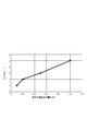
- FIG. 7 shows the relationship between the total number of image formations (the number of durable sheets) and the accumulated amount of paper dust in the carrier liquid in the image forming apparatus 100 of the present embodiment.
- most of the paper dust is collected together with the liquid developer by the intermediate transfer roller cleaner 26 and is transported to the waste liquid storage container 35 together with the liquid developer, so it does not reach the first separation and extraction device 37 .
- a very small amount of paper dust may be mixed in the liquid developer collected by the drum cleaner 19. Since the liquid developer collected by the drum cleaner 19 is conveyed to the first separation and extraction device 37, as shown in FIG. 7, the amount of accumulated paper dust contained in the carrier liquid is constant (here Increase to 0.08g).
- the accumulated amount of paper dust is suppressed to "about 0.08 g" even when the durable sheet number of 1,000,000 sheets has passed. That is, the accumulated amount of paper dust does not reach up to "4 g" where the gloss difference becomes "2 °" or more and the image quality may be deteriorated.
- the paper powder having a weight difference exceeding “2 °” is not included in the carrier liquid even after the number of sheets has passed. Therefore, it is not necessary to replace the liquid developer.
- the fixing device 25 (see FIG. 1) emits ultraviolet light (UV light of, for example, 10 to 20 mJ) to the toner image secondarily transferred to the recording material S conveyed by the conveyance belt 24. To harden the carrier liquid, and fix the toner image on the recording material S.
- the output upper limit of the ultraviolet light by the fixing device 25 is “20 mJ”.
- the exposure energy required to cure the carrier liquid by the irradiation of ultraviolet light is "8 mJ" or more.
- FIG. 11 shows the relationship between the paper powder content in the UV-curable liquid developer and the exposure energy required to cure the carrier liquid when paper dust (specifically, talc) is mixed with the carrier liquid. .
- the exposure energy required to cure the carrier liquid increases.
- the exposure energy "20 mJ" is used as the boundary value of fixing possibility (indicated by a dotted line in FIG. 11).
- the carrier liquid is “6 g”, the carrier liquid is The exposure energy required for curing exceeds 20 mJ, making fixing difficult. This is because talc (a metal ion such as magnesium) contained in the carrier liquid inhibits the curing reaction of the monomer contained in the carrier liquid.
- the paper powder having a weight (6 g) whose exposure energy exceeds “20 mJ” is contained in the carrier liquid, as shown in FIG. It is after about 520,000 copies.
- the exposure energy exceeds “20 mJ”
- the fixing by the ultraviolet light irradiation becomes difficult.
- the accumulated amount of paper dust contained in the carrier liquid increases to a fixed amount (here, 0.08 g) according to the number of durable sheets.
- a fixed amount here 0.08 g
- the accumulated amount of paper dust is suppressed to "about 0.08 g". That is, the accumulated amount of paper dust does not reach to "6 g" where exposure energy exceeds "20 mJ" and fixation by ultraviolet light irradiation becomes difficult.
- the amount of paper dust which is difficult to be fixed by the irradiation of the ultraviolet light is not included in the carrier liquid even after the number of sheets has passed. Therefore, it is not necessary to replace the liquid developer.
- the drum cleaner 19 and the first separation and extraction device 37 are connected to each other by the drum recovery liquid transport pipe 190, while the intermediate transfer roller cleaner 26 and the waste liquid storage container 35 are connected. They are connected to one another by an add-on recovery liquid transport pipe 260.
- the liquid developer collected by the drum cleaner 19 is separated into the toner and the carrier liquid by the first separation and extraction device 37, and the separated carrier liquid is reused.
- the liquid developer collected by the intermediate transfer roller cleaner 26 is conveyed to the waste liquid storage container 35, it is not separated into the toner and the carrier liquid by the first separation and extraction device 37.
- the carrier liquid in which the components are degraded is not reused by containing a large amount of paper dust.
- the carrier liquid in which the components are degraded is not reused by containing a large amount of paper dust.
- deterioration of the carrier liquid to be reused can be suppressed, it is possible to obtain an effect that the liquid developer can be repeatedly used longer than in the past. Then, if the liquid developer can be repeatedly used for a longer time than in the past, the running cost associated with the replacement of the liquid developer can be suppressed, and the time and effort of the user can be reduced.
- the liquid developer collected by the transfer roller cleaner 27 is held as it is by the transfer roller cleaner 27.
- the liquid developer collected by the transfer roller cleaner 27 It may be configured to be transported to 35.
- Such a second embodiment will be described with reference to FIG. Below, the case where an ultraviolet curing type liquid developer is used will be described as an example.
- symbol is attached
- the transfer roller cleaner 27 and the waste liquid storage container 35 are connected to each other by a double recovery liquid transport pipe 270 as a recovery transport path.
- the transfer roller cleaner 27 and the waste liquid storage container 35 are connected by the second recovery liquid transport pipe 270 so that the liquid developer collected by the transfer roller cleaner 27 can be transported to the waste storage container 35.
- the liquid developer collected by the transfer roller cleaner 27 is transported to the waste liquid storage container 35 by a screw (not shown) or the like provided in the double recovery liquid transport pipe 270.
- a pump (not shown) may be provided in the middle of the second recovery liquid transport pipe 270 so that it can be transported by this pump.
- the liquid developer may be transported using its own weight without being provided with a pump if it can be transported by its own weight drop.
- the present image forming apparatus is particularly suitable for use with a liquid developer.
Landscapes
- Physics & Mathematics (AREA)
- General Physics & Mathematics (AREA)
- Wet Developing In Electrophotography (AREA)
- Cleaning In Electrography (AREA)
- Fixing For Electrophotography (AREA)
- Electrostatic Charge, Transfer And Separation In Electrography (AREA)
Abstract
感光体(13)上の静電潜像を液体現像剤によりトナー像に現像する現像装置(16)と、感光体(13)のトナー像が転写される中間転写体(20)と、中間転写体(20)のトナー像を記録材に転写する転写部材(21)と、感光体(13)に残る液体現像剤を回収する感光体清掃部(19)と、転写部材(21)に残る液体現像剤を回収する転写部材清掃部(27)と、液体現像剤からトナーとキャリア液とを分離する分離装置(37)と、液体現像剤を収容する収容容器(35)と、感光体清掃部(19)により回収された液体現像剤を分離装置(37)に搬送可能に、感光体清掃部(19)と分離装置(37)とを接続する分離用搬送路(190)と、転写部材清掃部(27)により回収された液体現像剤を分離装置(37)を介さずに収容容器(35)に搬送可能に、転写部材清掃部(27)と収容容器(35)とを接続する回収用搬送路(270)と、を備える。
Description
本発明は、液体現像剤を用いて画像を形成する電子写真方式の画像形成装置に関する。
従来から、トナーとキャリア液とを含む液体現像剤を用いて画像を形成する画像形成装置が知られている。液体現像剤を用いる画像形成装置では、感光ドラムや中間転写ローラなどから画像形成工程で使用されなかった液体現像剤を回収し、再利用することが行われている。従来では、トナー像の転写後に感光ドラム、中間転写ローラ、転写ローラなどから回収した液体現像剤を分離装置に搬送し、分離装置により液体現像剤中のトナーとキャリア液とを分離させて、分離したキャリア液を再利用する処理が行われている(特許文献1)。
ところで、記録材としての紙に接触してトナー像を紙に転写する転写ローラ等から回収されるキャリア液には、紙粉などの異物が混入しやすい。そのため、分離後のキャリア液に紙粉等が混入する虞が生ずる。
本発明は、上述の問題に鑑みてなされ、キャリア液を再利用する構成であっても、再利用するキャリア液への異物の混入を低減することができる画像形成装置の提供を目的とする。
本発明に係る画像形成装置は、感光体と、前記感光体に形成された静電潜像をトナーとキャリア液とからなる液体現像剤によりトナー像に現像する現像装置と、前記感光体からトナー像が一次転写される中間転写体と、前記中間転写体に一次転写されたトナー像を記録材に二次転写する転写部材と、一次転写後に前記感光体上に残る液体現像剤を回収する感光体清掃部と、二次転写後に前記転写部材上に残る液体現像剤を回収する転写部材清掃部と、液体現像剤からトナーとキャリア液とを分離する分離装置と、液体現像剤を収容する収容容器と、前記感光体清掃部により回収された液体現像剤を前記分離装置に搬送可能に、前記感光体清掃部と前記分離装置とを接続する分離用搬送路と、前記転写部材清掃部により回収された液体現像剤を前記分離装置を介さずに前記収容容器に搬送可能に、前記転写部材清掃部と前記収容容器とを接続する回収用搬送路と、を備える。
本発明の一態様によれば、キャリア液を再利用する構成であっても、再利用するキャリア液への異物の混入を低減することができる。
本発明のその他の特徴及び利点は、添付図面を参照とした以下の説明により明らかになるであろう。なお、添付図面においては、同じ若しくは同様の構成には、同じ参照番号を付す。
<第一実施形態>
[画像形成装置]
本実施形態の画像形成装置について説明する。まず、本実施形態の画像形成装置の構成について、図1を用いて説明する。図1に示す画像形成装置100は、記録材S(用紙、OHPシートなどのシート材など)にトナー画像を形成する電子写真方式のデジタルプリンタである。画像形成装置100は、画像信号に基づいて動作し、カセット11a、11bから順次搬送される記録材Sに、画像形成部12で形成したトナー像を転写し、その後、定着することで画像を得ている。画像信号は、不図示のスキャナやパーソナルコンピュータなどの外部端末などから画像形成装置100に送られる。
[画像形成装置]
本実施形態の画像形成装置について説明する。まず、本実施形態の画像形成装置の構成について、図1を用いて説明する。図1に示す画像形成装置100は、記録材S(用紙、OHPシートなどのシート材など)にトナー画像を形成する電子写真方式のデジタルプリンタである。画像形成装置100は、画像信号に基づいて動作し、カセット11a、11bから順次搬送される記録材Sに、画像形成部12で形成したトナー像を転写し、その後、定着することで画像を得ている。画像信号は、不図示のスキャナやパーソナルコンピュータなどの外部端末などから画像形成装置100に送られる。
画像形成部12は、感光体としての感光ドラム13、帯電器14、レーザ露光装置15、現像器16、ドラムクリーナ19を備えている。帯電器14により表面が帯電された感光ドラム13上に、画像信号に応じてレーザ露光装置15からレーザ光Eが照射され、感光ドラム13上に静電潜像が形成される。この静電潜像は、現像器16によりトナー像として現像される。本実施形態の場合、現像装置としての現像器16には、分散媒であるキャリア液に分散質である粉体のトナーを分散させた液体現像剤Dが収容されており、この液体現像剤Dを用いて現像を行う。
液体現像剤Dは、混合器としてのミキサ31において、キャリア液CにトナーTを所定の比率で混合、分散させて生成され、現像器16へ供給される。補給用のキャリア液Cはキャリア容器としてのキャリアタンク32に、補給用のトナーTはトナー容器としてのトナータンク33にそれぞれ収容されている。そして、ミキサ31内のキャリア液CとトナーTの混合状態に応じて、それぞれのタンクからキャリア液C又はトナーTがミキサ31へ供給される。ミキサ31は、不図示のモータにより駆動される攪拌羽根が収容されており、供給されたキャリア液とトナーTとを攪拌することで混合し、キャリア液中にトナーを分散させている。なお、本実施形態の場合、ミキサ31の容量は現像液重量に換算して約2000gである。
ミキサ31から現像器16へ供給された液体現像剤Dは、現像器16の供給区画16aにおいてコートローラ17によって、現像ローラ18にコートされ(供給され)、現像に使用される。現像ローラ18は、表面に液体現像剤を担持して搬送し、感光ドラム13上に形成された静電潜像をトナーで現像する。現像後に現像ローラ18に残留したキャリア液CとトナーTは、現像器16の回収区画16bへ回収される。ここで、コートローラ17から現像ローラ18への液体現像剤Dのコート、及び、現像ローラ18から感光ドラム13上の静電潜像への現像は、それぞれ電界を用いて行う。
感光ドラム13上に形成されたトナー像は、電界を用いて中間転写ローラ20に一次転写され、中間転写ローラ20と転写ローラ21とで形成されたニップ部(二次転写部)へ搬送される。中間転写ローラ20への一次転写後に感光ドラム13上(感光体上)に残る液体現像剤(トナーTとキャリア液C)はドラムクリーナ19によって回収される。感光体清掃部としてのドラムクリーナ19は、例えばゴムからなるブレード状の部材で構成されて、線圧30(g/cm)で感光ドラム13に当接される。なお、中間転写ローラ20と転写ローラ21とは、少なくとも何れかが無端状のベルトであってもよい。
カセット11a、11bに収容された記録材Sは、搬送ローラなどにより構成される給送部22a、22bによりレジスト搬送部23へ向けて搬送される。レジスト搬送部23は、中間転写ローラ20に転写されたトナー像のタイミングに合わせて、中間転写ローラ20と転写ローラ21とのニップ部へ記録材Sを搬送する。
中間転写ローラ20と転写ローラ21とのニップ部では、通過する記録材Sにトナー像が二次転写され、トナー像が転写された記録材Sは、搬送ベルト24によって定着装置25へ搬送され、記録材Sに転写されたトナー像を定着する。トナー像が定着した記録材Sは、機外へ排出され、画像工程が完了する。本実施形態では、定着装置25は熱定着方式が採用される。この方式の場合、定着装置25は記録材Sを上下から挟み且つお互いに圧で押し合う2つのローラを有し、この2つのローラはその表面温度が約200℃に維持される。これによって、所定のプロセススピード(例えば600mm/s)で搬送される記録材Sの表面は、トナーが溶融するガラス転移点である60℃以上の温度に維持される。トナーが溶融することで、記録材S上にトナーが定着される。ただし、液体現像剤Dとして紫外線硬化型の液体現像剤を使用する場合、定着装置25は紫外線光(UV光)を照射して液体現像剤を硬化させる。キャリア液が硬化することで、記録材S上にトナーが定着される。
中間転写体としての中間転写ローラ20と、転写部材としての転写ローラ21にはそれぞれ、中間転写ローラクリーナ26、転写部材清掃部としての転写ローラクリーナ27が設けられる。中間転写ローラクリーナ26は、中間転写ローラ20から二次転写後に中間転写ローラ20に残る液体現像剤(トナーTとキャリア液C)を回収する。転写ローラクリーナ27は、転写ローラ21から二次転写後に転写ローラ21に残る液体現像剤(トナーTとキャリア液C)を回収する。本実施形態においては、中間転写ローラクリーナ26及び転写ローラクリーナ27はいずれもゴムからなるブレード状の部材で構成され、線圧30(g/cm)で中間転写ローラ20と転写ローラ21にそれぞれ当接される。ただし、中間転写ローラ20と転写ローラ21に残留した液体現像剤(主にトナーT)を回収する方式はこれに限られない。例えばローラ状の部材を当接させ、中間転写ローラ20上(中間転写体上)、転写ローラ21上(転写部材上)のトナーTを電界によって剥離する方式であってもよい。
[液体現像剤]
次に、液体現像剤Dについて説明する。本実施形態の画像形成装置100で用いる液体現像剤Dとしては、従来から使用されている液体現像剤を使用してもよいが、紫外線硬化型の液体現像剤Dを用いてもよい。そこで、紫外線硬化型の液体現像剤Dについて説明する。
次に、液体現像剤Dについて説明する。本実施形態の画像形成装置100で用いる液体現像剤Dとしては、従来から使用されている液体現像剤を使用してもよいが、紫外線硬化型の液体現像剤Dを用いてもよい。そこで、紫外線硬化型の液体現像剤Dについて説明する。
液体現像剤Dは、カチオン重合性液状モノマー、光重合開始剤、カチオン重合性液状モノマーに不溶なトナー粒子を含む紫外線硬化型液体現像剤である。また、カチオン重合性液状モノマーがビニルエーテル化合物であり、光重合開始剤が、次の一般式(1)で表される化合物である。

トナー粒子は、色を発する色材をトナー樹脂で内包している。また、トナー樹脂と色材とともに、帯電制御剤等、他の材料を含有してもよい。トナー粒子の製造方法としては、色材を分散させ、樹脂を徐々に重合内包させるコアシェルベーションや、樹脂等を溶融させ、色材を樹脂内部へ内包させる内粉砕法などの公知技術を用いてもよい。トナー樹脂は、エポキシ、スチレンアクリル系等を用いている。色を発する色材は、一般有機無機顔料でよい。また、製造上、トナー分散性を高めるため、分散剤を用いているが、シナジストも可能である。
他方、キャリア液である硬化性液体は、トナー表面の電荷をもたせる荷電制御剤と、紫外線である紫外線(UV)照射で酸を発生する光重合剤、さらに酸により結合するモノマーで構成されている。モノマーは、カチオン重合反応により、ポリマー化するビニルエーテル化合物である。また、光重合剤とは別に、増感剤を含有してもよい。光重合により、保存性が低下するため、カチオン重合禁止剤を10~5000ppm入れてもよい。他に、帯電制御補助剤、他添加材等を用いる場合もある。
この現像剤の紫外線硬化剤(モノマー)は、ビニルエーテル基が一つある一官能モノマー(式2)が約10%(重量%)とビニルエーテル基が二つある二官能モノマー(式3)を約90%混合したものである。

光重合開始剤としては下記の(式4)で表されるものを0.1%混合している。この光重合開始剤を用いることにより、良好な定着を可能しつつも、イオン性の光酸発生剤を用いる場合と異なり、高抵抗な液体現像剤が得られる。

なお、カチオン重合性液状モノマーが、ジシクロペンタジエンビニルエーテル、シクロヘキサンジメタノールジビニルエーテル、トリシクロデカンビニルエーテル、トリメチロールプロパントリビニルエーテル、2-エチル-1,3-ヘキサンジオールジビニルエーテル、2,4-ジエチル-1,5-ペンタンジオールジビニルエーテル、2-ブチル-2-エチル-1,3-プロパンジオールジビニルエーテル、ネオペンチルグリコールジビニルエーテル、ペンタエリスリトールテトラビニルエーテル及び1,2-デカンジオールジビニルエーテルからなる群より選ばれる化合物であることが望ましい。
更に、帯電制御剤としては、公知のものが利用できる。具体的な化合物としては、亜麻仁油、大豆油などの油脂;アルキド樹脂、ハロゲン重合体、芳香族ポリカルボン酸、酸性基含有水溶性染料、芳香族ポリアミンの酸化縮合物、ナフテン酸コバルト、ナフテン酸ニッケル、ナフテン酸鉄、ナフテン酸亜鉛、オクチル酸コバルト、オクチル酸ニッケル、オクチル酸亜鉛、ドデシル酸コバルト、ドデシル酸ニッケル、ドデシル酸亜鉛、ステアリン酸アルミニウム、2-エチルヘキサン酸コバルトなどの金属石鹸類;石油系スルホン酸金属塩、スルホコハク酸エステルの金属塩などのスルホン酸金属塩類;レシチンなどの燐脂質;t-ブチルサリチル酸金属錯体などのサリチル酸金属塩類;ポリビニルピロリドン樹脂、ポリアミド樹脂、スルホン酸含有樹脂、ヒドロキシ安息香酸誘導体などが挙げられる。
[液体現像剤の搬送]
次に、本実施形態における液体現像剤Dの搬送について、図2を用いて説明する。まず、上述のようにドラムクリーナ19で回収した液体現像剤は、第一分離抽出装置37及び第二分離抽出装置34に送られる。なお、現像後に現像ローラ18上に残留し、現像器16の回収区画16bへ回収した液体現像剤は、ミキサ31に戻されるが、第一分離抽出装置37、第二分離抽出装置34に搬送するようにしてもよい。
次に、本実施形態における液体現像剤Dの搬送について、図2を用いて説明する。まず、上述のようにドラムクリーナ19で回収した液体現像剤は、第一分離抽出装置37及び第二分離抽出装置34に送られる。なお、現像後に現像ローラ18上に残留し、現像器16の回収区画16bへ回収した液体現像剤は、ミキサ31に戻されるが、第一分離抽出装置37、第二分離抽出装置34に搬送するようにしてもよい。
他方、中間転写ローラクリーナ26で回収した液体現像剤は、収容容器としての廃液収容容器35に廃液Wとして収容される。また、本実施形態において、転写ローラクリーナ27で回収した液体現像剤は、量が少量であるため、そのまま転写ローラクリーナ27に保持するものとしている。ただし、後述する第二実施形態のように(図8参照)、転写ローラクリーナ27で回収した液体現像剤が廃液収容容器35に廃液Wとして収容される構成であってもよい。なお、廃液収容容器35は、画像形成装置100の装置本体100a(図1参照)に対し交換自在に設けられていてよい。その場合、廃液収容容器35に収容された廃液Wが所定量を超えると、ユーザに対し廃液収容容器35の交換を報知できるようにすると好ましい。
分離装置としての第一分離抽出装置37は、詳しくは後述するが、キャリア液とトナーとを分離する際に、キャリア液と、トナー及び紙粉などの異物を含み得る廃液Wとを分離する。分離された廃液Wは、廃液収容容器35に回収される。
第二分離抽出装置34は、詳しくは後述するが、第一分離抽出装置37で分離、抽出されたキャリア液中から、トナー以外でキャリア液中の不要な成分を分離する。具体的には、キャリア液中に含まれる体積抵抗率の低い物質(低抵抗キャリア)が挙げられる。上述のようにキャリア液を形成する物質中には荷電制御剤が含まれており、低抵抗キャリアの成分としては主に荷電制御剤である。ここで、荷電制御剤の体積抵抗率は、一例として、1.0E+9Ωcmである。なお、荷電制御剤を含まないキャリア液の体積抵抗率は、1.0E+12Ωcmである。
液体現像剤Dの搬送について、より具体的に説明する。キャリアタンク32とトナータンク33からミキサ31への輸送管には、それぞれ、電磁弁41,42が設けられている。電磁弁41,42は、ミキサ31へのキャリア液CとトナーTの供給量を調整する。ミキサ31からは、液体現像剤供給部としてのポンプ44を用いて現像に必要な液体現像剤Dが現像器16へ供給される。
現像器16の回収区画16bへ回収した液体現像剤は、ポンプ43によってミキサ31に戻される。回収区画16bで回収された液体現像剤は、現像などに使用されておらず殆ど劣化していないためである。
図2に示すように、ドラムクリーナ19と第一分離抽出装置37とは、分離用搬送路としてのドラム回収液輸送管190によって互いに接続されている。ドラムクリーナ19と第一分離抽出装置37とがドラム回収液輸送管190によって接続されることで、ドラムクリーナ19で回収された液体現像剤は第一分離抽出装置37に搬送可能になっている。ドラムクリーナ19で回収された液体現像剤は、ドラム回収液輸送管190の途中に設けられたポンプ48によって第一分離抽出装置37に搬送される。第一分離抽出装置37で分離、抽出されたキャリア液(液体現像剤)は、電磁弁51により第二分離抽出装置34に搬送される。
他方、本実施形態では、中間転写ローラクリーナ26と廃液収容容器35とは中転回収液輸送管260によって互いに接続されている。中間転写ローラクリーナ26と廃液収容容器35とが中転回収液輸送管260によって接続されることで、中間転写ローラクリーナ26で回収された液体現像剤は廃液収容容器35に搬送可能になっている。中間転写ローラクリーナ26で回収される液体現像剤は、ドラムクリーナ19で回収される液体現像剤に比較して少量であり、またトナー濃度(トナー及びキャリア液の合計重量に対するトナー重量の割合:TD比とも呼ぶ)や粘度が比較的に高い。そのため、中間転写ローラクリーナ26で回収された液体現像剤は、中転回収液輸送管260内に設けられたスクリュー(不図示)等によって廃液収容容器35に搬送される。勿論、これに限らず、中転回収液輸送管260の途中にポンプ(不図示)を設け、このポンプにより搬送可能としてもよい。
第一分離抽出装置37、第二分離抽出装置34で分離されたキャリア液は再利用可能であり、再利用するために、キャリア供給部としての電磁弁45によってキャリアタンク32へ搬送される。他方、第一分離抽出装置37で分離された廃液W(主にトナー)は再利用が難しいため、排出用搬送路としての廃液輸送管370に設けられた電磁弁47によって廃液収容容器35へ搬送される。また、第二分離抽出装置34で分離された廃液W(主に低抵抗キャリア)についても再利用が難しいため、第二分離抽出装置34と廃液収容容器35とを接続する輸送管に設けられた電磁弁52によって廃液収容容器35へ搬送される。
次に、上述の第一分離抽出装置37におけるトナーとキャリアの分離と、第二分離抽出装置34におけるキャリア液の成分分離とについて、図3乃至図6を用いて説明する。本実施形態において、第一分離抽出装置37は、電界を用いて液体現像剤をトナーとキャリア液とに分離し、キャリア液とトナーとを別々に抽出する装置である。第二分離抽出装置34は、第一分離抽出装置37で分離、抽出されたキャリア液中から、電界を用いて低抵抗キャリア(主に荷電制御剤)を分離、抽出する装置である。なお、第一分離抽出装置37と第二分離抽出装置34とは同じ構成であってよい。そこで、以下では、図3乃至図6を用いて第二分離抽出装置34について説明し、第一分離抽出装置37については同じ構成に対しカッコ書きで符号を付し、作用が異なる部分について補足的に説明する。
まず、第二分離抽出装置34を設ける理由について説明する。キャリア液は再利用処理が繰り返されることにより、キャリア液中に体積抵抗率の低い物質(低抵抗キャリア)が蓄積する。すると、液体現像剤全体の抵抗が下がり、画像不良が発生する恐れがある。特に、ベタ画像(感光ドラムの画像形成可能領域の全面に形成したトナー像であり、画像比率(印字率)が100%の場合を言う)のような高濃度の画像を形成した場合、出力画像に占めるキャリア液の割合が少ないため、特に抵抗が下がり易い。本実施形態では、このようなキャリア液の体積抵抗率の低下を抑制すべく、第二分離抽出装置34を設けている。
第一分離抽出装置37で分離されたキャリア液(液体現像剤)は、図3及び図4に矢印で示すように、第二分離抽出装置34の入口34bから液体収容容器346内に搬送される。そして、液体収容容器346内のバッファ容器348(図4参照)に供給される。本実施形態では、バッファ容器348を第二分離抽出装置34に備えさせているが、容器単体で設けてもよい。バッファ容器348に供給されたキャリア液は、ポンプ34cにより搬送され、フィルタ34dを通過する。
フィルタ34dを通過したキャリア液は、図4に示すように、供給トレイ346aに投入される。なお、第二分離抽出装置34では、フィルタ34dを省略して、第一分離抽出装置37で分離、抽出されたキャリア液を直接、供給トレイ346aに投入するようにしてもよい。供給トレイ346aに投入されたキャリア液は、第二分離抽出装置34において低抵抗キャリア(主に荷電制御剤)と高抵抗キャリアに分けられる。そして、抽出された低抵抗キャリアは廃液収容容器35に送られ、抽出された高抵抗キャリア(キャリア液)はキャリアタンク32へ搬送される。
図4及び図5に示すように、液体収容容器346内には、コート電極部材341、導電性の電極ローラ342、回収装置350などが配置されている。コート電極部材341と電極ローラ342とで、その間を液体現像剤が通過可能な1対の第二電極を構成し、電極ローラ342が片側の第二電極342aを、コート電極部材341が他側の第二電極341aを、それぞれ有する。液体収容容器346は、キャリア液を収容可能な容器であって、上述の供給トレイ346aと、後述するように再利用可能となったキャリア液が排出される排出部346bと、廃液となった液体現像剤の回収部354とを有している。
電極ローラ342は、例えば中実ステンレスによって外径がφ40mmに形成された芯金表層にウレタンゴム弾性層を一体成型により形成した導電性のローラである。電極ローラ342は、不図示の駆動モータによって外部から駆動が入力され、所定方向(図4、図5の矢印方向)に回転する。本実施形態では、駆動モータの回転速度は2000rpmとしている。そして、電極ローラ342は、駆動モータの回転を減速させて、例えば400rpmの回転速度で回転する。
コート電極部材341は、図5及び図6に示すように、電極ローラ342の一部と第二隙間としての隙間347を介して配置される。隙間347の電極ローラ342の回転方向上流端部347aには、供給トレイ346aが接続されている。そして、上述のように供給トレイ346aに投入されたキャリア液は、上流端部347aから隙間347内に供給される。隙間347の電極ローラ342の回転軸線方向両端部は封止されており、隙間347に供給されたキャリア液は、電極ローラ342の回転に伴って隙間347内を回転方向下流側に搬送される。隙間347の電極ローラ342の回転方向下流端部347bには、排出部346bが接続されている(図6参照)。そして、隙間347を通過したキャリア液が排出部346bから輸送管346cを介してキャリアタンク32に送られる(図2参照)。
上述のように、電極ローラ342と隙間347を介して配置されるコート電極部材341は、少なくとも液体が通過する部分341xの表面が導電性素材によって形成されていている。また、コート電極部材341は、例えば中実ステンレスによって幅400mmに形成されている。また、液体が通過する部分341xは、電極ローラ342の一部を収容する形状を有し、この部分341xの電極ローラ342と対向する面は、電極ローラ342の表面と所定距離(即ち、隙間347)を保つように湾曲した形状となっている。この所定距離は、例えば0.2mmである。本実施形態の場合、上述のようにドラムクリーナ19で回収され、供給トレイ346aから隙間347に供給されたキャリア液は、この隙間347を通過することで、低抵抗キャリアと高抵抗キャリアとに分離される。
回収装置350は、電極ローラ342の回転方向に関してコート電極部材341の下流側に位置し、電極ローラ342に担持された低抵抗キャリアを回収する。回収装置350は、回収ローラ351と、ブレード部材352と、不図示の電圧印加装置とを有する。
回収ローラ351は、例えば中実ステンレスによって外径がφ20に形成された導電性のローラであり、電極ローラ342に当接するように配置されている。そして、回収ローラ351は、電極ローラ342に接触して、図4、図5の矢印方向に従動回転する。なお、回収ローラ351の回転速度は、例えば800rpmである。
[第一分離抽出装置の補足説明]
上述のようにドラムクリーナ19で回収された液体現像剤は、図4及び図5に矢印で示すように、第一分離抽出装置37の入口37bから液体収容容器376内に搬送される。そして、液体収容容器376内のバッファ容器378に供給される。バッファ容器378に供給された液体現像剤は、ポンプ37cにより搬送され、フィルタ37dを通過する。
上述のようにドラムクリーナ19で回収された液体現像剤は、図4及び図5に矢印で示すように、第一分離抽出装置37の入口37bから液体収容容器376内に搬送される。そして、液体収容容器376内のバッファ容器378に供給される。バッファ容器378に供給された液体現像剤は、ポンプ37cにより搬送され、フィルタ37dを通過する。
フィルタ37dを通過した液体現像剤は、図4に示すように、供給トレイ376aに投入される。詳しくは後述するように、供給トレイ376aに投入された液体現像剤は、第一分離抽出装置37においてトナーとキャリア液に分けられる。そして、抽出されたトナーは廃液収容容器35に送られ、抽出されたキャリア液は、上述のように第二分離抽出装置34へ搬送される。
図4及び図5に示すように、液体収容容器376内には、コート電極部材371、導電性の電極ローラ372、トナー回収装置380などが配置されている。コート電極部材371と電極ローラ372とで、その間を液体現像剤が通過可能な1対の第一電極を構成し、電極ローラ372が片側の第一電極372aを、コート電極部材371が他側の第一電極371aを、それぞれ有する。液体収容容器376は、液体現像剤を収容可能な容器であって、上述の供給トレイ376aと、キャリア液が排出される排出部376bと、廃液となった液体現像剤の回収部384とを有している。
電極ローラ372は、不図示の駆動モータによって外部から駆動が入力され、所定方向(図4、図5の矢印方向)に回転する。本実施形態では、駆動モータの回転速度は2000rpmとしている。なお、第二分離抽出装置34の電極ローラ342と第一分離抽出装置37の電極ローラ372とを駆動する駆動モータは、同じであっても別であってもよい。
コート電極部材371は、図5及び図6に示すように、電極ローラ372の一部と第一隙間としての隙間377を介して配置される。隙間377の電極ローラ342の回転方向上流端部377aには、供給トレイ376aが接続されている。そして、上述のように供給トレイ376aに投入された液体現像剤は、上流端部377aから隙間377内に供給される。隙間377に供給された液体現像剤は、電極ローラ372の回転に伴って隙間377内を回転方向下流側に搬送される。隙間377の電極ローラ372の回転方向下流端部377bには、排出部376bが接続されている(図4参照)。そして、隙間377を通過した液体現像剤が排出部376bから輸送管376cを介して第二分離抽出装置34に送られる(図2、図4参照)。
上述のように、電極ローラ372と隙間377を介して配置されるコート電極部材371は、少なくとも液体が通過する部分371xの表面が導電性素材によって形成されていている。コート電極部材371と電極ローラ372との間には、不図示の高圧電源によってトナーが電極ローラ342側に移動する電界が生じるように電圧が印加される。即ち、隙間377には、トナーが電極ローラ372に引き寄せられるような電界が生じるような電圧が印加されている。
本実施形態では、荷電制御剤によりトナーがマイナス帯電するため、例えば電極ローラ372にマイナス300V、コート電極部材371にマイナス1000Vが印加される。この結果、液体現像剤が隙間377を通過している間に、トナーが電極ローラ372に担持され、トナーとキャリア液とが分離される。分離されたキャリア液は、隙間377の下流端部377bに接続される排出部376bに排出される。
トナー回収装置380は、電極ローラ372の回転方向に関してコート電極部材371の下流側に位置し、電極ローラ372に担持されたトナーを回収する。トナー回収装置380は、回収ローラ381とブレード部材382とを有する。
回収ローラ381は、電極ローラ372に向けて付勢され、電極ローラ372に当接する。そして、回収ローラ381は電極ローラ372に当接して、図4、図5の矢印方向に従動回転する。電極ローラ372及び回収ローラ381は互いに略平行に配置され、回転軸線方向両端部が液体収容容器376に回転自在に支持されている。回収ローラ381と電極ローラ372との間には、不図示の高圧電源によって回収ローラ側にトナーが移動する電界が生じるように電圧が印加される。本実施形態では、例えば電極ローラ372にマイナス300V、回収ローラ381にマイナス200Vが印加される。これにより、電極ローラ372に担持され、回収ローラ381まで搬送されたトナーが、電極ローラ372から回収ローラ381に移動する。
ブレード部材382は、回収ローラ381に接触して回収ローラ上のトナーを掻き取る。ブレード部材382は、電極ローラ372と回収ローラ381とが接触している位置に対して回収ローラ381の回転方向下流側で、回収ローラ381に対してカウンター方向に接触するように配置されている。上述のように電極ローラ372から回収ローラ381に移動したトナーは、ブレード部材382により掻き取られ、回収部384に送られる。回収部384により回収されたトナーは、上述したように、廃液収容容器35に送られる。
なお、第一分離抽出装置37は、トナーとキャリア液との分離、抽出が行われれば、第二分離抽出装置34と異なる構成であってもよい。
ところで、上述したように、第一分離抽出装置37、第二分離抽出装置34では、電気泳動によって電気的に正負の極性を有するトナー、あるいはキャリア液中の成分(主に荷電制御剤)を分離している。ただし、液体現像剤に炭酸カルシウムやタルク等の成分が含まれている場合、第一分離抽出装置37及び第二分離抽出装置34ではこれら炭酸カルシウムやタルクを分離させるのが難しい。
即ち、トナー画像を形成する記録材Sが紙である場合、紙には白地部を形成する填料として、炭酸カルシウムやタルク(マグネシウムなどの金属化合物)が含まれている。これら炭酸カルシウムやタルクの含有比率は、紙の種類によって異なる。また、記録材Sがロール紙でなく裁断された形状のカット紙である場合には特に紙端部に紙粉が発生しやすく、カット紙に直接接触する中間転写ローラクリーナ26に、紙粉などの異物が付着しやすい。それ故、中間転写ローラクリーナ26により回収された液体現像剤には、紙粉が比較的に多く混入され得る。そして、二次転写に伴う強電界を経た液体現像剤中の炭酸カルシウムやタルクは電気的に正負いずれの極性も取り得るため、第一分離抽出装置37及び第二分離抽出装置34ではキャリア液から炭酸カルシウムやタルクを分離することが難しい。
従来の画像形成装置では、中間転写ローラクリーナ26により回収されたキャリア液、つまりは炭酸カルシウムやタルク等の成分を比較的に高い割合で含有し変質した可能性があるキャリア液は、第一分離抽出装置37に搬送されていた。しかし、上述したように、第一分離抽出装置37(及び第二分離抽出装置34)ではキャリア液から炭酸カルシウムやタルクを分離させるのが難しく、変質したキャリア液が再利用されることがあった。変質したキャリア液が再利用された場合、定着後の記録材上のトナー像の色味や光沢などが変わる、紫外線光の照射による硬化性が低下することによりトナーが記録材に定着し難くなるなどの不都合が生じ得る。
上記したキャリア液の変質の度合いは、キャリア液中に含まれる紙粉の蓄積量(紙粉蓄積量)によって変わる。そこで、キャリア液中の紙粉蓄積量について説明する。ミキサ31内において通紙N枚目におけるキャリア液中の紙粉蓄積量をX(N)、現像ローラ18により現像に供される記録材一枚当たりのキャリア消費量を「a」、記録材一枚当たりの紙粉発生量を「p」とする。これらの単位はグラム(g)であり、また記録材SはA4カット紙である。そして、発生した紙粉は、中間転写ローラクリーナ26により全て回収されるものとする。また、ミキサ31内のキャリア液の総量を「A」とし、現像ローラ18で記録材一枚当たりに消費した分のキャリア液が新品のキャリア液で常に補充されるものとする。さらに、中間転写ローラクリーナ26で回収された紙粉はミキサ31内で均等に分散され、そのキャリア液が次の記録材Sにトナー像を形成する際に用いられるものとする。この場合、通紙N枚目におけるキャリア液中の紙粉蓄積量X(N)は、以下の式(1)で表すことができる。
X(N)=X(N-1)-(a/A)×X(N-1)+p ・・・(式1)
X(N)=X(N-1)-(a/A)×X(N-1)+p ・・・(式1)
式(1)において、右辺第一項「X(N-1)」は、記録材Sの(N-1)枚目におけるキャリア液中の紙粉蓄積量を表す。右辺第二項「(a/A)×X(N-1)」は、(N-1)枚目までにキャリア液中に蓄積された紙粉のうち、N枚目のトナー像の形成時にミキサ31外へ排出される紙粉量を表す。また、右辺第三項「p」は上記した通り、記録材一枚当たりの紙粉発生量を表す。
ここで、現像ローラ18により現像に供される記録材一枚当たりのキャリア量を「0.05g」、記録材一枚当たりにドラムクリーナ19内とミキサ31内にあるキャリア液は「2000g」、記録材一枚当たりの紙粉発生量を「2.0×10⁻⁴g」とする。図9に、中間転写ローラクリーナ26により回収されたキャリア液が第一分離抽出装置37に搬送される従来の画像形成装置における、累計の画像形成枚数(耐久枚数)とキャリア液中の紙粉蓄積量X(n)との関係を示す。
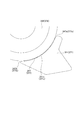
図10に、紙粉(詳しくはその成分中にタルクを含む)をキャリア液に混ぜた場合における、液中の紙粉含有量と定着後のトナー像の画質変化(具体的には光沢)との関係を示す。図10において、横軸はキャリア液に対する紙粉含有量(w%)を示し、縦軸は画質変化を光沢差(Δグロス)で示している。光沢を計測する光沢計には、日本電色工業製の光沢計「PG‐II」を用いた。一般的に、光沢は光沢差「2°」以上で、ユーザは画像低下を認識し得る。そこで、ここでは光沢差「2°」を画質低下の境界値としている(図10中に点線で示す)。図10から理解できるように、紙粉含有量が「0.2w%」、ここではキャリア液中に含まれる紙粉の重量にして「4g」を超えると、光沢差が「2°」を超えて画質低下が顕著になる。
ミキサ31と現像器16との間で「2000g(2リットル)」の液体現像剤が循環されており、記録材一枚ごとに「1.0×10⁻⁴g」の紙粉が中間転写ローラクリーナ26により回収されるものとする。従来の画像形成装置の場合、光沢差が「2°」を超える重量(4g)の紙粉がキャリア液中に含まれるのは、図9に示すように、累計の画像形成枚数(耐久枚数)が約2.7万枚を超えてからである。このように、従来の画像形成装置では、4gを超える紙粉がキャリア液に含まれると、光沢差が「2°」以上となって画質低下を生じさせ得る。これに対し、画像形成装置では、適切に画像を形成することが可能な記録材Sの枚数(耐用枚数などと呼ばれる)として例えば約100万枚を想定している。それ故に、従来の画像形成装置の場合には、約2.7万枚の記録材Sに画像形成する毎に液体現像剤を入れ替える必要があり、液体現像剤の入れ替えに伴うランニングコストが増えるし、またユーザの手間がかかる。
上記点に鑑みて、本実施形態では、上述したように、中間転写ローラクリーナ26で回収した液体現像剤を廃液収容容器35に搬送可能なように、中間転写ローラクリーナ26と廃液収容容器35とを中転回収液輸送管260によって接続している。即ち、中間転写ローラクリーナ26で回収した液体現像剤を第一分離抽出装置37でなく、廃液収容容器35に搬送する。こうすると、上記の光沢差が「2°」を超える重量の紙粉がキャリア液中に含まれるまでにかかる耐久枚数を、従来に比較して増やすことができるようになる。以下、この点について説明する。
図7に、本実施形態の画像形成装置100における累計の画像形成枚数(耐久枚数)とキャリア液中の紙粉蓄積量との関係を示す。本実施形態の場合、ほとんどの紙粉は主に中間転写ローラクリーナ26により液体現像剤と共に回収され、液体現像剤と共に廃液収容容器35に搬送されることから、第一分離抽出装置37に到達しない。ただし、ドラムクリーナ19により回収される液体現像剤に、非常に僅かな量の紙粉が混入し得る。ドラムクリーナ19で回収した液体現像剤は第一分離抽出装置37に搬送されることから、図7に示すように、耐久枚数に応じてキャリア液中に含まれる紙粉蓄積量は一定量(ここでは0.08g)まで増加する。この場合、100万枚という耐用枚数を経過した時点でも、紙粉蓄積量が「約0.08g」に抑制される。つまり、光沢差が「2°」以上となって画質低下を生じさせ得る「4g」まで、紙粉蓄積量は達しない。このように、本実施形態の画像形成装置100では、耐用枚数を経過しても光沢差が「2°」を超える重量の紙粉がキャリア液中に含まれることがない。従って、液体現像剤の入れ替えを行う必要がない。
また、本実施形態の場合、定着装置25(図1参照)は搬送ベルト24により搬送される記録材Sに二次転写されたトナー像に対し、例えば「10~20mJ」の紫外線光(UV光)を照射してキャリア液を硬化させ、記録材Sにトナー像を定着させている。なお、本実施形態の場合、定着装置25による紫外線光の出力上限は「20mJ」とする。また、紫外線光の照射によりキャリア液を硬化させるのに必要な露光エネルギーは「8mJ」以上である。
キャリア液を硬化させるのに必要な露光エネルギーは、キャリア液の状態変化によって変わる。図11に、紫外線硬化型の液体現像剤中の紙粉含有量と、キャリア液に紙粉(詳しくはタルク)を混ぜた場合にキャリア液を硬化させるのに必要な露光エネルギーとの関係を示す。図11に示すように、液中の紙粉含有量(w%)が増えるにつれて、キャリア液を硬化させるのに必要な露光エネルギーは増していく。本実施形態の場合、キャリア液を硬化させるのに必要な露光エネルギーが「20mJ」以上になると、出力上限を超えてしまい、キャリア液を硬化させることができず、トナー像を記録材Sに定着させることが難しくなる。そこで、ここでは露光エネルギー「20mJ」を定着可否の境界値としている(図11中に点線で示す)。
図11から理解できるように、本実施形態の場合、紙粉含有量が「0.3w%」、ここではキャリア液中に含まれる紙粉の重量にして「6g」を超えると、キャリア液を硬化させるのに必要な露光エネルギーが「20mJ」を超え、定着が難しくなる。これは、キャリア液中に含まれるタルク(マグネシウム等の金属イオン)がキャリア液に含まれるモノマーの硬化反応を阻害するからである。
従来の画像形成装置の場合、露光エネルギーが「20mJ」を超える重量(6g)の紙粉がキャリア液中に含まれるのは、図12に示すように、累計の画像形成枚数(耐久枚数)が約5.2万枚を超えてからである。このように、従来の画像形成装置では、6gを超える紙粉がキャリア液に含まれると、露光エネルギーが「20mJ」超え、紫外線光照射による定着が難しくなる。
これに対し、本実施形態の画像形成装置100では、図7に示したように、耐久枚数に応じてキャリア液中に含まれる紙粉蓄積量は一定量(ここでは0.08g)まで増加するが、100万枚を経過した時点でも、紙粉蓄積量が「約0.08g」に抑制される。つまり、露光エネルギーが「20mJ」超えて紫外線光照射による定着が難しくなる「6g」まで、紙粉蓄積量は達しない。このように、本実施形態の画像形成装置100では、耐用枚数を経過しても紫外線光の照射による定着が難しくなる量の紙粉がキャリア液中に含まれることがない。従って、液体現像剤の入れ替えを行う必要がない。
以上のように、本実施形態では、ドラムクリーナ19と第一分離抽出装置37とがドラム回収液輸送管190によって互いに接続されるのに対して、中間転写ローラクリーナ26と廃液収容容器35とが中転回収液輸送管260によって互いに接続されている。この場合、ドラムクリーナ19で回収された液体現像剤は第一分離抽出装置37によりトナーとキャリア液とに分離され、分離されたキャリア液は再利用される。他方、中間転写ローラクリーナ26で回収された液体現像剤は廃液収容容器35に搬送されるので、第一分離抽出装置37によりトナーとキャリア液とに分離されることがない。即ち、紙粉を多く含んだ液体現像剤が第一分離抽出装置37により分離されないので、紙粉を多く含むことで成分が変質したキャリア液を再利用することがない。こうして、本実施形態では再利用するキャリア液の変質を抑制できるので、もって従来よりも長くに亘って液体現像剤を繰り返し利用できる、という効果が得られる。そして、従来よりも長くに亘って液体現像剤を繰り返し利用できれば、液体現像剤の入れ替えに伴うランニングコストを抑制でき、またユーザの手間を減らすことができる。
<第二実施形態>
上述した第一実施形態では、転写ローラクリーナ27で回収した液体現像剤はそのまま転写ローラクリーナ27に保持するものとしたがこれに限られず、転写ローラクリーナ27で回収した液体現像剤を廃液収容容器35に搬送する構成であってもよい。こうした第二実施形態について、図8を用いて説明する。以下では、紫外線硬化型の液体現像剤を用いる場合を例に説明する。なお、上述した第一実施形態と同様の構成については同じ符号を付し、説明を簡略又は省略する。
上述した第一実施形態では、転写ローラクリーナ27で回収した液体現像剤はそのまま転写ローラクリーナ27に保持するものとしたがこれに限られず、転写ローラクリーナ27で回収した液体現像剤を廃液収容容器35に搬送する構成であってもよい。こうした第二実施形態について、図8を用いて説明する。以下では、紫外線硬化型の液体現像剤を用いる場合を例に説明する。なお、上述した第一実施形態と同様の構成については同じ符号を付し、説明を簡略又は省略する。
図8に示すように、本実施形態では、転写ローラクリーナ27と廃液収容容器35とが回収用搬送路としての二転回収液輸送管270によって互いに接続される。転写ローラクリーナ27と廃液収容容器35とが二転回収液輸送管270によって接続されることで、転写ローラクリーナ27で回収された液体現像剤は廃液収容容器35に搬送可能になっている。転写ローラクリーナ27で回収された液体現像剤は、二転回収液輸送管270内に設けられたスクリュー(不図示)等によって廃液収容容器35に搬送される。あるいは、二転回収液輸送管270の途中にポンプ(不図示)を設け、このポンプにより搬送可能としてもよい。
<他の実施形態>
なお、液体現像剤の搬送は、ポンプを用いる以外に、例えば、自重落下で搬送できる場合はポンプを設けず自重を用いた搬送方式としてもよい。
なお、液体現像剤の搬送は、ポンプを用いる以外に、例えば、自重落下で搬送できる場合はポンプを設けず自重を用いた搬送方式としてもよい。
本画像形成装置は、特に液体現像剤を用いるものに用いて好適である。
本発明は上記実施の形態に制限されるものではなく、本発明の精神及び範囲から離脱することなく、様々な変更及び変形が可能である。従って、本発明の範囲を公にするために、以下の請求項を添付する。
13…感光体(感光ドラム)、16…現像装置(現像器)、19…感光体清掃部(ドラムクリーナ)、20…中間転写体(中間転写ローラ)、21…転写部材(転写ローラ)、25…定着装置、27…転写部材清掃部(転写ローラクリーナ)、31…混合器(ミキサ)、32…キャリア容器(キャリアタンク)、33…トナー容器(トナータンク)、35…収容容器(廃液収容容器)、37…分離装置(第一分離抽出装置)、45…キャリア供給部(電磁弁)、100…画像形成装置、100a…装置本体、190…分離用搬送路(ドラム回収液輸送管)、270…回収用搬送路(二転回収液輸送管)、370…排出用搬送路(廃液輸送管)
Claims (6)
- 感光体と、
前記感光体に形成された静電潜像をトナーとキャリア液とからなる液体現像剤によりトナー像に現像する現像装置と、
前記感光体からトナー像が一次転写される中間転写体と、
前記中間転写体に一次転写されたトナー像を記録材に二次転写する転写部材と、
一次転写後に前記感光体上に残る液体現像剤を回収する感光体清掃部と、
二次転写後に前記転写部材上に残る液体現像剤を回収する転写部材清掃部と、
液体現像剤からトナーとキャリア液とを分離する分離装置と、
液体現像剤を収容する収容容器と、
前記感光体清掃部により回収された液体現像剤を前記分離装置に搬送可能に、前記感光体清掃部と前記分離装置とを接続する分離用搬送路と、
前記転写部材清掃部により回収された液体現像剤を前記分離装置を介さずに前記収容容器に搬送可能に、前記転写部材清掃部と前記収容容器とを接続する回収用搬送路と、を備える、画像形成装置。 - 前記分離装置により液体現像剤から分離されたトナーを前記収容容器に搬送可能に、前記分離装置と前記収容容器とを接続する排出用搬送路を備える、
請求項1に記載の画像形成装置。 - トナーを収容するトナー容器と、
キャリア液を収容するキャリア容器と、
液体現像剤を収容し、前記トナー容器から供給されたトナーと、前記キャリア容器から供給されたキャリア液とを混合、分散する混合器と、
前記キャリア容器に、前記分離装置で液体現像剤からトナーを分離したキャリア液を供給するキャリア供給部と、を備える、
請求項1または請求項2に記載の画像形成装置。 - 前記収容容器は、装置本体に対し交換自在に設けられている、
請求項1乃至3のいずれか1項に記載の画像形成装置。 - 二次転写後に前記中間転写体上に残る液体現像剤を回収する中間転写体清掃部と、を有し、前記中間転写体清掃部により回収された液体現像剤は前記分離装置を介さずに前記収容容器に搬送される、
請求項1乃至4のいずれか1項に記載の画像形成装置。 - 前記分離装置により分離されたトナーは前記収容容器に搬送される、
請求項1乃至5のいずれか1項に記載の画像形成装置。
Applications Claiming Priority (2)
| Application Number | Priority Date | Filing Date | Title |
|---|---|---|---|
| JP2017213242A JP2019086595A (ja) | 2017-11-02 | 2017-11-02 | 画像形成装置 |
| JP2017-213242 | 2017-11-02 |
Publications (1)
| Publication Number | Publication Date |
|---|---|
| WO2019087887A1 true WO2019087887A1 (ja) | 2019-05-09 |
Family
ID=66331818
Family Applications (1)
| Application Number | Title | Priority Date | Filing Date |
|---|---|---|---|
| PCT/JP2018/039440 WO2019087887A1 (ja) | 2017-11-02 | 2018-10-24 | 画像形成装置 |
Country Status (2)
| Country | Link |
|---|---|
| JP (1) | JP2019086595A (ja) |
| WO (1) | WO2019087887A1 (ja) |
Families Citing this family (1)
| Publication number | Priority date | Publication date | Assignee | Title |
|---|---|---|---|---|
| KR20220005504A (ko) | 2019-04-26 | 2022-01-13 | 가부시키가이샤 니콘. 에시로루 | 적층체 및 그 제조 방법 |
Citations (4)
| Publication number | Priority date | Publication date | Assignee | Title |
|---|---|---|---|---|
| JP2006243129A (ja) * | 2005-03-01 | 2006-09-14 | Seiko Epson Corp | 画像形成装置 |
| JP2008122919A (ja) * | 2006-10-19 | 2008-05-29 | Kyocera Mita Corp | 液体現像剤のトナー濃度測定装置及びそれを備えた画像形成装置 |
| JP2009175697A (ja) * | 2007-12-28 | 2009-08-06 | Seiko Epson Corp | 画像形成装置及び画像形成装置の制御方法 |
| US20150338781A1 (en) * | 2014-05-23 | 2015-11-26 | Océ Printing Systems GmbH & Co. KG | Method of producing low-migration printed materials |
-
2017
- 2017-11-02 JP JP2017213242A patent/JP2019086595A/ja active Pending
-
2018
- 2018-10-24 WO PCT/JP2018/039440 patent/WO2019087887A1/ja active Application Filing
Patent Citations (4)
| Publication number | Priority date | Publication date | Assignee | Title |
|---|---|---|---|---|
| JP2006243129A (ja) * | 2005-03-01 | 2006-09-14 | Seiko Epson Corp | 画像形成装置 |
| JP2008122919A (ja) * | 2006-10-19 | 2008-05-29 | Kyocera Mita Corp | 液体現像剤のトナー濃度測定装置及びそれを備えた画像形成装置 |
| JP2009175697A (ja) * | 2007-12-28 | 2009-08-06 | Seiko Epson Corp | 画像形成装置及び画像形成装置の制御方法 |
| US20150338781A1 (en) * | 2014-05-23 | 2015-11-26 | Océ Printing Systems GmbH & Co. KG | Method of producing low-migration printed materials |
Also Published As
| Publication number | Publication date |
|---|---|
| JP2019086595A (ja) | 2019-06-06 |
Similar Documents
| Publication | Publication Date | Title |
|---|---|---|
| JP2016224424A (ja) | 分離装置 | |
| JP2007225893A (ja) | 液体現像装置及び画像形成装置 | |
| JP2006349735A (ja) | 画像形成装置 | |
| US10451991B2 (en) | Image forming apparatus | |
| WO2019087887A1 (ja) | 画像形成装置 | |
| US6892045B2 (en) | Image forming apparatus and convey control method for recycle toner | |
| US10310419B2 (en) | Image forming apparatus and carrier separating device | |
| JP2018013631A (ja) | 画像形成装置 | |
| JP6170874B2 (ja) | 現像装置、現像方法、及び画像形成装置 | |
| US10908537B2 (en) | Image forming apparatus | |
| JP2010026309A (ja) | 液体現像剤、および液体現像剤を用いた画像形成装置 | |
| JP6040571B2 (ja) | 画像形成装置 | |
| WO2015163000A1 (ja) | 現像装置及び画像形成装置 | |
| JP7452215B2 (ja) | クリーニングブレード、プロセスカートリッジ、及び画像形成装置 | |
| WO2019098030A1 (ja) | 画像形成装置 | |
| JP3968285B2 (ja) | 画像形成装置及びプロセスカートリッジ | |
| JP5516261B2 (ja) | 電子写真記録装置 | |
| JP2009042667A (ja) | 液体現像装置及びこれを搭載した画像形成装置 | |
| JP2011164125A (ja) | 現像装置及び画像形成装置 | |
| JP2019159248A (ja) | 現像装置およびそれを備えた画像形成装置 | |
| JP2018132652A (ja) | クリーニングブレード、プロセスカートリッジ及び画像形成装置 | |
| JP2004258517A (ja) | 画像形成装置及びプロセスカートリッジ | |
| JP2017044957A (ja) | 画像形成装置 | |
| JP2016142941A (ja) | 画像形成装置 | |
| JP2010210718A (ja) | 現像装置、プロセスカートリッジ、及び、画像形成装置 |
Legal Events
| Date | Code | Title | Description |
|---|---|---|---|
| 121 | Ep: the epo has been informed by wipo that ep was designated in this application |
Ref document number: 18872782 Country of ref document: EP Kind code of ref document: A1 |
|
| NENP | Non-entry into the national phase |
Ref country code: DE |
|
| 122 | Ep: pct application non-entry in european phase |
Ref document number: 18872782 Country of ref document: EP Kind code of ref document: A1 |