WO2019087623A1 - 表示装置、表示装置の制御方法 - Google Patents
表示装置、表示装置の制御方法 Download PDFInfo
- Publication number
- WO2019087623A1 WO2019087623A1 PCT/JP2018/035692 JP2018035692W WO2019087623A1 WO 2019087623 A1 WO2019087623 A1 WO 2019087623A1 JP 2018035692 W JP2018035692 W JP 2018035692W WO 2019087623 A1 WO2019087623 A1 WO 2019087623A1
- Authority
- WO
- WIPO (PCT)
- Prior art keywords
- display device
- intoxication
- unit
- hmd
- motion
- Prior art date
Links
Images


Classifications
-
- G—PHYSICS
- G06—COMPUTING; CALCULATING OR COUNTING
- G06F—ELECTRIC DIGITAL DATA PROCESSING
- G06F3/00—Input arrangements for transferring data to be processed into a form capable of being handled by the computer; Output arrangements for transferring data from processing unit to output unit, e.g. interface arrangements
- G06F3/01—Input arrangements or combined input and output arrangements for interaction between user and computer
- G06F3/011—Arrangements for interaction with the human body, e.g. for user immersion in virtual reality
-
- G—PHYSICS
- G09—EDUCATION; CRYPTOGRAPHY; DISPLAY; ADVERTISING; SEALS
- G09G—ARRANGEMENTS OR CIRCUITS FOR CONTROL OF INDICATING DEVICES USING STATIC MEANS TO PRESENT VARIABLE INFORMATION
- G09G5/00—Control arrangements or circuits for visual indicators common to cathode-ray tube indicators and other visual indicators
-
- G—PHYSICS
- G06—COMPUTING; CALCULATING OR COUNTING
- G06F—ELECTRIC DIGITAL DATA PROCESSING
- G06F3/00—Input arrangements for transferring data to be processed into a form capable of being handled by the computer; Output arrangements for transferring data from processing unit to output unit, e.g. interface arrangements
- G06F3/01—Input arrangements or combined input and output arrangements for interaction between user and computer
- G06F3/011—Arrangements for interaction with the human body, e.g. for user immersion in virtual reality
- G06F3/012—Head tracking input arrangements
-
- G—PHYSICS
- G06—COMPUTING; CALCULATING OR COUNTING
- G06F—ELECTRIC DIGITAL DATA PROCESSING
- G06F3/00—Input arrangements for transferring data to be processed into a form capable of being handled by the computer; Output arrangements for transferring data from processing unit to output unit, e.g. interface arrangements
- G06F3/01—Input arrangements or combined input and output arrangements for interaction between user and computer
- G06F3/017—Gesture based interaction, e.g. based on a set of recognized hand gestures
-
- G—PHYSICS
- G06—COMPUTING; CALCULATING OR COUNTING
- G06F—ELECTRIC DIGITAL DATA PROCESSING
- G06F3/00—Input arrangements for transferring data to be processed into a form capable of being handled by the computer; Output arrangements for transferring data from processing unit to output unit, e.g. interface arrangements
- G06F3/16—Sound input; Sound output
- G06F3/167—Audio in a user interface, e.g. using voice commands for navigating, audio feedback
-
- G—PHYSICS
- G06—COMPUTING; CALCULATING OR COUNTING
- G06T—IMAGE DATA PROCESSING OR GENERATION, IN GENERAL
- G06T11/00—2D [Two Dimensional] image generation
-
- G—PHYSICS
- G06—COMPUTING; CALCULATING OR COUNTING
- G06T—IMAGE DATA PROCESSING OR GENERATION, IN GENERAL
- G06T19/00—Manipulating 3D models or images for computer graphics
-
- G—PHYSICS
- G09—EDUCATION; CRYPTOGRAPHY; DISPLAY; ADVERTISING; SEALS
- G09G—ARRANGEMENTS OR CIRCUITS FOR CONTROL OF INDICATING DEVICES USING STATIC MEANS TO PRESENT VARIABLE INFORMATION
- G09G5/00—Control arrangements or circuits for visual indicators common to cathode-ray tube indicators and other visual indicators
- G09G5/36—Control arrangements or circuits for visual indicators common to cathode-ray tube indicators and other visual indicators characterised by the display of a graphic pattern, e.g. using an all-points-addressable [APA] memory
- G09G5/37—Details of the operation on graphic patterns
- G09G5/377—Details of the operation on graphic patterns for mixing or overlaying two or more graphic patterns
-
- H—ELECTRICITY
- H04—ELECTRIC COMMUNICATION TECHNIQUE
- H04N—PICTORIAL COMMUNICATION, e.g. TELEVISION
- H04N5/00—Details of television systems
- H04N5/222—Studio circuitry; Studio devices; Studio equipment
- H04N5/262—Studio circuits, e.g. for mixing, switching-over, change of character of image, other special effects ; Cameras specially adapted for the electronic generation of special effects
- H04N5/265—Mixing
-
- H—ELECTRICITY
- H04—ELECTRIC COMMUNICATION TECHNIQUE
- H04N—PICTORIAL COMMUNICATION, e.g. TELEVISION
- H04N5/00—Details of television systems
- H04N5/64—Constructional details of receivers, e.g. cabinets or dust covers
-
- G—PHYSICS
- G08—SIGNALLING
- G08B—SIGNALLING OR CALLING SYSTEMS; ORDER TELEGRAPHS; ALARM SYSTEMS
- G08B21/00—Alarms responsive to a single specified undesired or abnormal condition and not otherwise provided for
- G08B21/02—Alarms for ensuring the safety of persons
Definitions
- the present invention relates to a technique for presenting a mixed reality space which is a composite space of a real space and a virtual space.
- MR Mated Reality
- a video see-through HMD Head Mounted Display
- CG Computer Graphics
- a subject is imaged by a charge coupled device such as a CCD to obtain digital image data of the subject, and an MR image (mixed reality space image) in which a CG image is superimposed on the digital image data is liquid crystal or organic EL Etc. to the wearer via a display device such as
- a display device such as
- the HMD transmits an image captured by the HMD to the external device.
- the external device calculates the position and orientation of the HMD from the captured image received from the HMD, generates a superimposed image in which the CG image is superimposed on the captured image based on the calculation result, and transmits the generated superimposed image to the HMD.
- the HMD displays the superimposed image received from the external device.
- the HMD user can experience the MR space by wearing the HMD.
- Patent Document 1 proposes a technology for reducing motion sickness by suppressing the amount of information visually recognized by an HMD user.
- Patent Document 1 discloses a process of suppressing the amount of information to be visually recognized when the movement amount of the virtual camera is equal to or more than a predetermined amount.
- the HMD user may not recognize motion that is likely to cause video sickness and may feel video sickness.
- the present invention has been made in view of such problems, and provides a technique for reducing video sickness of a user who observes a display device.
- One embodiment of the present invention is a display device, which is an acquisition unit for acquiring motion information indicating the motion of the display device, and information indicating a drunk motion in which the motion information is preset as a motion that is easy to get drunk.
- the apparatus is characterized by including notification means for notifying a warning.
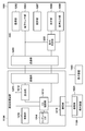
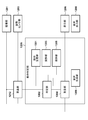
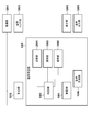
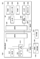
- FIG. 2 is a block diagram showing an example of the functional configuration of each of an HMD 1101 and an image processing apparatus 1104.
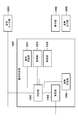
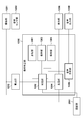
- FIG. 11 is a block diagram showing an example of the functional configuration of an operation determination unit 1205.
- the figure which shows an example of drunk operation The figure which shows an example of drunk operation.
- the figure which shows an example of drunk operation The figure which shows an example of drunk operation.
- movement determination. The figure which shows an example of operation
- FIG. 11 is a view showing an example of the arrangement of information stored in an operation definition unit 1301.
- FIG. 2 is a block diagram showing an example of the functional configuration of each of an HMD 1101 and an image processing apparatus 1104.
- FIG. 11 is a block diagram showing an example of the functional configuration of an operation determination unit 1205. The figure which shows an example of operation
- FIG. 16 is a view showing an example of the configuration of a table held by the operation definition unit 1301.
- FIG. 11 is a block diagram showing an example of the functional configuration of an operation determination unit 1205. The figure which shows the structural example of the table which the score part 2501 hold
- FIG. 2 is a block diagram showing an example of the functional configuration of each of an HMD 1101 and an image processing apparatus 1104.
- FIG. 11 is a block diagram showing an example of the functional configuration of an operation determination unit 1205.
- the system according to the present embodiment includes an HMD 1101, a display device 1103, an image processing device 1104, and an operation device 1105.
- the HMD 1101 and the image processing apparatus 1104 are configured to be capable of data communication with each other via a wireless or wired network.
- a wireless network between the HMD 1101 and the image processing apparatus 1104 for example, WLAN (Wireless Local Area Network) or WPAN (Wireless Personal Area Network) can be applied.
- the HMD 1101 and the image processing apparatus 1104 may perform data communication with each other through one or more communication devices.
- a display device 1103 and an operation device 1105 are connected to the image processing apparatus 1104.
- the HMD 1101 is used as an example of a head mounted display.
- a head mounted display other than the HMD 1101 may be used.
- not only the head mounted display but also other types of display such as a handheld display may be used.
- the imaging unit 1202 captures a moving image in the physical space, and sequentially transmits images of the frames of the captured moving image (captured image in the physical space) to the image processing apparatus 1104 via the communication unit 1204.
- the imaging unit 1202 is attached to the HMD 1101 so as to be located near the eyes of a user who wears the HMD 1101 on the head (hereinafter, may be referred to as an HMD user).
- the posture sensor unit 1203 is a sensor such as an acceleration sensor or a gyro sensor.
- the attitude sensor unit 1203 is used for “attitude information representing its own attitude (for example, quarter turn on)”, “own acceleration”, and “each axis (X axis, Y) constituting a local coordinate system based on its own position and attitude. Measure its own angular velocity ") about the axis (Z axis).
- the posture information, the angular velocity, and the acceleration measured by the posture sensor unit 1203 may be referred to as the posture information, the angular velocity, and the acceleration of the HMD 1101, respectively.
- the attitude sensor unit 1203 transmits attitude information of the measured information to the image processing apparatus 1104 via the communication unit 1204.
- the posture sensor unit 1203 measures not only all of its posture information, angular velocity, and acceleration, but may be one or more of them, instead of or in addition to these, its own position, etc. Other relevant information may be measured.
- the display unit 1206 is attached to the HMD 1101 so as to be located in front of the HMD user's eyes, and displays an image or characters output from the operation determination unit 1205.
- the audio output unit 1208 is attached at a position where audio can be output to the HMD user's ear (both ears or one ear), and outputs audio based on the audio signal output from the operation determination unit 1205 .
- the motion determination unit 1205 determines whether the motion of the HMD 1101 (head of the HMD user) based on the measurement result by the posture sensor unit 1203 corresponds to a prescribed motion set in advance as a motion prone to drunk. Then, if the motion of the HMD 1101 corresponds to a prescribed motion, the motion determination unit 1205 superimposes the information representing the warning on the image received from the image processing apparatus 1104 so as to notify the user of the warning and displays the display unit. Output to 1206. Also, if the motion of the HMD 1101 corresponds to a prescribed motion, the motion determination unit 1205 outputs a voice signal of voice representing a warning to the voice output unit 1208. Details of the operation determination unit 1205 will be described later using the block diagram of FIG.
- the control unit 1207 has a processor such as a CPU and a memory in which computer programs and data executed by the processor are stored.
- the processor executes processing using computer programs and data in the memory to control the operation of the entire HMD 1101 and to execute or control each processing described later on the assumption that the HMD 1101 performs.
- the communication unit 1204 functions as an interface for performing data communication with the image processing apparatus 1104.
- the image processing apparatus 1104 is a computer device such as a PC (personal computer), a WS (work station), a tablet terminal device or a smartphone.
- the communication unit 1211 functions as an interface for performing data communication with the HMD 1101.
- the calculation unit 1212 acquires the captured image and orientation information transmitted from the HMD 1101 via the communication unit 1211. Then, the calculation unit 1212 calculates the position of the imaging unit 1202 when the captured image is captured from the acquired captured image.
- the technique for calculating the position of the imaging device which imaged this captured image from a captured image is known, and any technique may be employ
- the position of the imaging device may be acquired based on a measurement value by a position sensor attached to the imaging device or a head-mounted display device having the imaging device, or imaging using a GPS
- the position of the device may be obtained. That is, the calculation unit 1212 may apply any technique as long as it can acquire the position of the imaging unit 1202 when imaging the captured image transmitted from the HMD 1101.
- the calculation unit 1212 also registers the relative posture relationship between the imaging unit 1202 and the posture sensor unit 1203 (this is known information and is stored in advance in the content DB 1214). Conversion). By this conversion, the attitude of the imaging unit 1202 can be obtained.
- the configuration for acquiring the orientation of the imaging unit 1202 is not limited to a specific configuration, and, for example, the orientation of the imaging unit 1202 when capturing the captured image from the captured image is determined by the above-described known method. You may
- the CG rendering unit 1213 constructs a virtual object using virtual object data registered in the content DB 1214, and arranges the constructed virtual object in the virtual space with the position and orientation defined by the virtual object data.
- the virtual object data includes model data defining the appearance of the virtual object such as geometry, color, texture, texture, etc. of the virtual object, data indicating a position and orientation at which the virtual object is arranged, data on a light source irradiating the virtual space, Etc.
- the CG drawing unit 1213 generates, as a virtual space image, an image of a virtual object viewed from the viewpoint (the position of the viewpoint is the position of the imaging unit 1202 and the attitude of the viewpoint is the attitude of the imaging unit 1202). Then, the CG rendering unit 1213 generates, as a mixed reality space image, a composite image obtained by combining the captured image acquired by the calculation unit 1212 from the HMD 1101 via the communication unit 1211 and the generated virtual space image. Then, the CG rendering unit 1213 transmits the generated mixed reality space image to the HMD 1101 via the communication unit 1211.
- the control unit 1219 has a processor such as a CPU and a memory in which computer programs and data executed by the processor are stored.
- the processor executes processing using computer programs and data in the memory, thereby controlling the operation of the entire image processing apparatus 1104 and executing or controlling each processing to be described later as being performed by the image processing apparatus 1104.
- the communication unit 1215 functions as an interface for connecting the controller device 1105 and the display device 1103 to the image processing apparatus 1104.
- the operation device 1105 is configured of a user interface such as a keyboard, and can input various instructions by the user's operation.
- the user interface is not limited to the keyboard, and may be another type of interface such as a mouse or a touch panel.
- the instruction input by the user's operation is input to the image processing apparatus 1104 via the communication unit 1221, and the control unit 1219 executes processing according to the instruction.
- the display device 1103 is configured of a CRT, a liquid crystal screen, or the like, and can display the processing result of the image processing apparatus 1104 as an image, characters, or the like. For example, an image output from the image processing apparatus 1104 to the HMD 1101 can be displayed on the display device 1103.
- the display device 1103 can also display a GUI for editing the contents of the warning (text and voice), the contents of a table to be described later, and the like.
- the display device 1103 may be a touch panel screen.
- All of the above-described functional units of the image processing apparatus 1104 may be implemented by hardware, but the calculation unit 1212 and the CG rendering unit 1213 may be implemented by software (computer program).
- the computer program is stored in the content DB 1214, and the control unit 1219 performs processing using the computer program to realize the functions of the calculation unit 1212 and the CG drawing unit 1213.
- the motion definition unit 1301 includes a plurality of types of “motions of the user's head (HMD 1101) such that the user observing the display unit 1206 wearing the HMD 1101 on the head” (intoxicated motion) For each of them, intoxication and detection order are stored.
- HMD 1101 the user's head
- intoxicated motion For each of them, intoxication and detection order are stored.
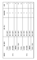
- FIG. 9 A configuration example of the information stored in the operation definition unit 1301 is shown in FIG.
- the table in FIG. 9 corresponds to “easy to get drunk” and “detection order” for each of four drunken motions “downward”, “roll operation”, “rapid acceleration”, and “biaxial rotation”. Is registered.
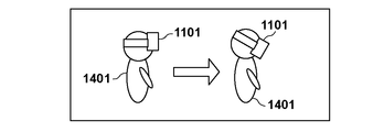
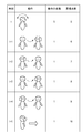
- FIG. 4A An example of a drunken motion "turning down” is shown in FIG. 4A.
- the head direction of the user 1401 with the HMD 1101 mounted on the head is from the state shown on the left side of FIG. 4A (the head is facing the front direction) to the right (head is positive) It is changing to the down angle direction).
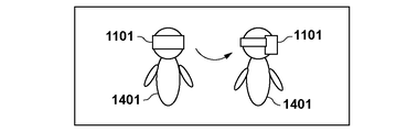
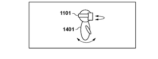
- FIG. 4B An example of the drunk operation "Roll operation” is shown in FIG. 4B.
- the head of the user 1401 wearing the HMD 1101 on the head is rotating in the Roll direction, as indicated by the arrow.
- FIG. 4C An example of a drunken motion "sudden acceleration" is shown in FIG. 4C.
- the user 1401 wearing the HMD 1101 on his head quickly shakes his / her neck to the left side of the user 1401 as shown by the arrow.
- FIG. 4D An example of a drunken motion "two axis rotation" is shown in FIG. 4D.
- the head of the user 1401 with the HMD 1101 mounted on the head rotates in two axes (for example, rotation in both the pan direction and the tilt direction) as indicated by two arrows.
- the operation definition unit 1301 is described as holding the table of FIG. 9, but the intoxicating operation registered in the table is not limited to the intoxicating operation shown in FIG. Other motion sickness motions may be registered instead or in addition to motions.
- the ease of detection and the detection order corresponding to the intoxication operation are not limited to those shown in FIG.
- the determination unit 1302 determines whether the motion of the HMD 1101 based on the measurement result by the posture sensor unit 1203 corresponds to a drunken operation.
- the determination unit 1302 first determines that the motion of the HMD 1101 based on the measurement result by the posture sensor unit 1203 is a drunken operation corresponding to the detection order “1”. It is determined whether or not it corresponds to “axis rotation”. As a result of this determination, when the movement of the HMD 1101 does not correspond to “biaxial rotation”, the determination unit 1302 determines that the movement of the HMD 1101 based on the measurement result by the posture sensor unit 1203 corresponds to the sickness operation corresponding to the detection order “2”.
- the determination unit 1302 determines that the movement of the HMD 1101 based on the measurement result by the posture sensor unit 1203 is a sickness operation corresponding to the detection order “3”. Determine whether it corresponds to "sudden acceleration”. As a result of this determination, when the movement of the HMD 1101 does not correspond to “sudden acceleration”, the determination unit 1302 determines that the movement of the HMD 1101 based on the measurement result by the posture sensor unit 1203 corresponds to the sickness operation corresponding to the detection order “4”. It is judged whether it corresponds to a certain "turn downward".
- the determination unit 1302 determines that the movement of the HMD 1101 based on the measurement result by the posture sensor unit 1203 is “normal operation” instead of drunk operation. to decide.
- the detection order for each movement is the order that easily leads to intoxication, and in the case of FIG. 9, “biaxial rotation”, “Roll operation”, “rapid acceleration”, and “turn downward” in that order It is a movement that easily leads to drunkenness.
- the intoxicating operation (“Facing downward”, “Roll operation”, “Roll operation") in which the determination unit 1302 indicates whether or not the motion of the HMD 1101 (head) corresponds to the intoxicating operation is shown in each of FIGS.
- the explanation will be made by taking “a sudden acceleration” and “biaxial rotation” as an example. As shown in FIG.
- the posture sensor unit 1203 uses its own position as the origin, the viewing direction of the imaging unit 1202 as the positive direction of the X axis, and the vertically upward direction of the imaging unit 1202 as the positive direction of the Y axis, X axis and Y axis Measure attitude information, angular velocity, and acceleration in a coordinate system with the axis orthogonal to Z as the Z axis.
- FIG. 5B a process in which the determination unit 1302 determines whether the movement of the HMD 1101 (head) is “down” will be described using FIG. 5B.
- the gravity axis of the posture sensor unit 1203 points in the negative direction of the Y axis as indicated by the arrow 1502.
- the posture sensor unit 1203 outputs “a vector indicating 1 G in the negative direction of the Y axis” as an acceleration.
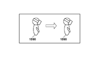
- the HMD user 1590 turns downward, as shown on the right side of FIG.
- the axis of the posture sensor unit 1203 is inclined, so the acceleration output from the posture sensor unit 1203 is a vector 1503 in the Y axis direction and the X axis direction. Is output as a vector 1504 of As the HMD user 1590 points downward, the magnitude of the vector 1504 in the X-axis direction increases. Therefore, for example, if the size of the vector in the X-axis direction is equal to or larger than the specified size, the determination unit 1302 determines that the movement of the HMD 1101 (head) is “downward”.
- the determining unit 1302 determines whether the motion of the HMD 1101 (head) is “Roll operation” will be described using FIG. 5C.
- the posture sensor unit 1203 indicates an angular velocity equal to or greater than the specified value as the angular velocity around the X axis as indicated by the arrow 1505. It is output. Therefore, for example, if the angular velocity around the X axis is equal to or greater than the specified value, the determination unit 1302 determines that the motion of the HMD 1101 (head) is “Roll operation”.
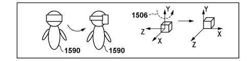
- FIG. 5D processing in which the determination unit 1302 determines whether or not the motion of the HMD 1101 (head) is “sudden acceleration” will be described using FIG. 5D.
- FIG. 5D As shown on the left side of FIG. 5D, when the HMD user 1590 shakes his / her neck fast as shown by the arrow, as shown on the right side of FIG. 5D, from the posture sensor unit 1203, as shown by the arrow 1506, An angular velocity equal to or greater than a specified value is output as the angular velocity. Therefore, for example, if the amount of change in angular velocity around the Y axis is equal to or greater than a specified value, the determination unit 1302 determines that the motion of the HMD 1101 (head) is “sudden acceleration”.
- an acceleration may be used instead of the angular velocity, and it may be determined that the movement of the HMD 1101 (head) is “a sudden acceleration” when an acceleration equal to or more than a predetermined value is obtained.
- FIG. 5E processing in which the determination unit 1302 determines whether or not the motion of the HMD 1101 (head) is “biaxial rotation” will be described using FIG. 5E.
- the HMD user 1590 rotates his / her head in pan and tilt directions as indicated by two arrows.
- an angular velocity equal to or greater than a specified value is output from the posture sensor unit 1203 as an angular velocity around the Y axis as indicated by an arrow 1508, and an angular velocity equal to or greater than a specified value is output as an angular velocity around a Z axis as indicated by an arrow 1507.
- Ru angular velocity equal to or greater than a specified value
- the HMD 1101 head It is determined that the motion of is “biaxial rotation”.
- the determination unit 1302 can determine which intoxicating motion the movement of the HMD 1101 (head) is based on the measurement result output from the posture sensor unit 1203.
- the process for determining what kind of movement the measurement result by the posture sensor unit 1203 indicates is not limited to a specific process.
- the character information stored in the holding unit 1303 corresponds to the intoxication corresponding to the intoxication operation.
- the character information is a character / character string (warning message) indicating a warning.
- the holding unit 1303 holds character information corresponding to each drunkiness. For example, in the case where the ease of drunkenness is two kinds of “drunken” and “immediately drunk”, the holding unit 1303 includes character information corresponding to “drunken”, character information corresponding to “immediately drunk”, Is stored.
- Holding unit 1303 may hold character information corresponding to each drunk operation in addition to or instead of holding character information corresponding to each drunkiness.
- the determination unit 1302 acquires, from the holding unit 1303, character information corresponding to the movement of the HMD 1101 (head) and / or character information corresponding to the sickness corresponding to the movement of the HMD 1101 (head). Become.
- the determination unit 1302 sends the acquired character information to the superimposing unit 1304.
- the determination unit 1302 determines that the motion of the HMD 1101 (head) corresponds to the intoxication operation, the determination unit 1302 corresponds to the intoxication corresponding to the intoxication operation among the audio data stored in the holding unit 1305. Get voice data.
- the holding unit 1305 holds audio data corresponding to the ease of drunkenness. For example, in the case where the ease of drunkenness is two types of “drunken” and “immediately drunk”, the holding unit 1305 includes voice data corresponding to “drunken”, voice data corresponding to “immediately drunk”, Is stored.
- the holding unit 1305 may hold voice data corresponding to each drunk operation, in addition to or instead of holding voice data corresponding to each drunkiness.
- the determination unit 1302 may obtain, from the holding unit 1305, audio data corresponding to the movement of the HMD 1101 (head) and / or audio data corresponding to the intoxication corresponding to the movement of the HMD 1101 (head). Become. Then, when the audio data is acquired from the storage unit 1305, the determination unit 1302 sends the acquired audio data to the audio generation unit 1306.
- the superimposing unit 1304 When the superimposing unit 1304 acquires the text information from the determining unit 1302, the superimposing unit 1304 superimposes the message indicated by the text information on the mixed reality space image received from the image processing apparatus 1104 via the communication unit 1204, and the message is superimposed.
- the mixed reality space image is sent to the display unit 1206.
- the superimposing unit 1304 does not acquire character information from the determining unit 1302, the superimposing unit 1304 sends the mixed reality space image received from the image processing apparatus 1104 via the communication unit 1204 to the display unit 1206.
- the superimposing unit 1304 receives the mixed reality space image shown in FIG. 6A from the image processing apparatus 1104.
- the superimposing unit 1304 displays the mixed reality space image of FIG. 6A received from the image processing apparatus 1104 without superimposing a warning message.
- the current motion of the HMD 1101 is a drunk operation and that the intoxication of the drunk operation is "doom gradually”.
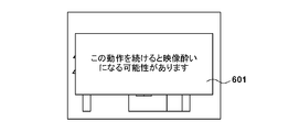
- the superimposing unit 1304 may become an image sickness if the HMD user continues the current operation (the operation of the head) on the mixed reality space image of FIG.
- the superimposing unit 1304 sends the mixed reality space image on which the warning message 601 is superimposed to the display unit 1206.
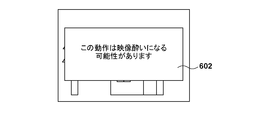
- the superimposing unit 1304 may cause the current motion (the motion of the head) of the HMD user to become video sick with the mixed reality space image of FIG. 6A received from the image processing apparatus 1104. It superimposes a warning message 602 for notifying that there is. Then, the superimposing unit 1304 sends the mixed reality space image on which the warning message 602 is superimposed to the display unit 1206.
- the contents and display method of the warning message are not limited to the specific contents and display method.
- the audio generation unit 1306 acquires audio data from the determination unit 1302, the audio generation unit 1306 generates an audio signal based on the audio data and sends the audio signal to the audio output unit 1208.
- a voice indicating a warning according to the drunkiness is output from the voice output unit 1208. That is, if the ease of drunkenness is "drunkenly", an audio output unit 1208 is used to notify that the HMD user may continue to perform the current motion (head motion) and may become video sickness.
- the audio output unit 1208 outputs a sound to notify that the current motion (motion of the head) of the HMD user may become video sickness. Ru.
- the determination unit 1302 does not send voice data to the voice generation unit 1306, and therefore no voice is output from the voice output unit 1208 .
- Notification of a warning to the HMD user may be performed only by the above display notification by the display unit 1206, or may be performed only by the above voice notification by the voice output unit 1208, or the above display notification and voice notification The warning may be notified by both.
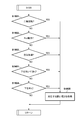
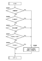
- FIG. 7 showing a flowchart of the processing.
- the HMD 1101 can display a mixed reality space image of a plurality of frames on the display unit 1206 by repeatedly performing the process according to the flowchart of FIG. 7.
- step S1701 the imaging unit 1202 captures a physical space to obtain a captured image of the physical space, and transmits the captured image to the image processing apparatus 1104 via the communication unit 1204.
- step S 1702 the orientation sensor unit 1203 acquires the orientation information, acceleration, and angular velocity of itself, and transmits the acquired orientation information to the image processing apparatus 1 104 via the communication unit 1204.
- step S 1703 the superimposing unit 1304 receives the mixed reality space image transmitted from the image processing apparatus 1104 via the communication unit 1204.
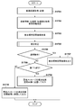
- the determination unit 1302 determines whether the movement of the HMD 1101 (head of the HMD user) based on the measurement results (posture information, angular velocity, acceleration) acquired by the posture sensor unit 1203 in step S1702 is a normal operation. Determine if it is a drunken motion. Details of the process in step S1705 will be described using the flowchart of FIG.
- step S 1801 the determination unit 1302 determines whether or not a part of or all of the measurement results acquired by the posture sensor unit 1203 have a detection order of “1” in the table of FIG. 9 held by the operation definition unit 1301. It is determined whether the condition corresponding to “rotation” is satisfied.
- An example of this determination process is as described with reference to FIG. 5E.
- the determination unit 1302 determines that the movement of the HMD 1101 (head) based on the measurement result by the posture sensor unit 1203 is “biaxial rotation”, and the process proceeds to step S1805.
- step S 1802 the determination unit 1302 is a drunk operation “Roll operation” in which a part or all of the measurement results acquired by the posture sensor unit 1203 is “2” in the detection order in the table of FIG. 9 held by the operation definition unit 1301. It is determined whether the conditions that apply to An example of this determination process is as described with reference to FIG. 5C.
- a part or all of the measurement result acquired by the posture sensor unit 1203 satisfies the condition corresponding to the drunk motion “Roll operation” (the movement indicated by the measurement result by the posture sensor unit 1203 is “Roll operation” Applicable) and.
- the determination unit 1302 determines that the movement of the HMD 1101 (head) based on the measurement result by the posture sensor unit 1203 is “Roll operation”, and the process proceeds to step S1805.
- a part or all of the measurement result acquired by the posture sensor unit 1203 does not satisfy the condition corresponding to the drunk operation "Roll operation” (the movement indicated by the measurement result by the posture sensor unit 1203 corresponds to "Roll operation” If not, the process proceeds to step S1803.
- step S 1803 the determination unit 1302 determines that the sickness operation “sudden” that the detection order is “3” in the table of FIG. 9 held by the operation definition unit 1301 for part or all of the measurement results acquired by the posture sensor unit 1203. It is determined whether the condition corresponding to “acceleration” is satisfied. An example of this determination process is as described with reference to FIG. 5D.
- the determination unit 1302 determines that the movement of the HMD 1101 (head) based on the measurement result of the posture sensor unit 1203 is “sudden acceleration”, and the process proceeds to step S1805.
- step S 1804 the determination unit 1302 determines that the motion of the lower part of the table shown in FIG. 9 held by the operation definition unit 1301 is “4” in part or all of the measurement results acquired by the posture sensor unit 1203. It is determined whether the condition corresponding to "turn on" is satisfied. An example of this determination process is as described with reference to FIG. 5B.
- the determination unit 1302 determines that the movement of the HMD 1101 (head) based on the measurement result by the posture sensor unit 1203 is “turn downward”, and the process proceeds to step S1805.
- the determination unit 1302 determines that the movement of the HMD 1101 (head) based on the measurement result of the posture sensor unit 1203 is a normal operation, and the process proceeds to step S1706.
- step S1805 from the table in FIG. 9, the motion definition unit 1301 holds the ease of motion corresponding to the motion of sickness corresponding to the motion of the HMD 1101 (head) based on the measurement result by the posture sensor unit 1203. get. Then, the process proceeds to step S1706.
- step S1706 as a result of the processing in step S1705, the determination unit 1302 determines whether the movement of the HMD 1101 (head) is a normal operation. If it is determined that the movement of the HMD 1101 (head) is a normal operation as a result of this determination, the processing proceeds to step S1707. On the other hand, if the motion of the HMD 1101 (head) is not a normal motion (any drunk motion), the process proceeds to step S1708.
- step S1707 the superimposing unit 1304 causes the display unit 1206 to display the mixed reality space image by transmitting the mixed reality space image received from the image processing apparatus 1104 in step S1703 described above to the display unit 1206.
- step S1708 the determination unit 1302 determines whether the intoxication acquired in step S1805 is “immediately intoxicated”. As a result of the determination, if the intoxication acquired in step S1805 is “immediately intoxicated”, the process proceeds to step S1709. On the other hand, if the drunkiness acquired in step S1805 above is “drunken gradually”, the process proceeds to step S1710.
- step S1709 the determination unit 1302 acquires, from the storage unit 1303, character information corresponding to “soon to get drunk”, and sends the acquired character information to the superposition unit 1304.
- the superimposing unit 1304 superimposes a warning message indicated by the character information received from the determining unit 1302 on the mixed reality space image received from the image processing apparatus 1104 in step S 1703 above, and the mixed reality space image on which the warning message is superimposed. It is sent to the display unit 1206.
- step S1710 the determination unit 1302 acquires character information corresponding to “deeply intoxicated” from the storage unit 1303, and sends the acquired character information to the superposition unit 1304.
- the superimposing unit 1304 superimposes a warning message indicated by the character information received from the determining unit 1302 on the mixed reality space image received from the image processing apparatus 1104 in step S 1703 above, and the mixed reality space image on which the warning message is superimposed. It is sent to the display unit 1206.
- step S1709 an audio notification based on audio data corresponding to "immediately drunk” is added to or instead of the display notification, and in step S1710 an audio notification based on audio data corresponding to "drunken gradually” is added to the display notification. Alternatively, it may be performed.
- the HMD user when the HMD user moves the head which easily causes the sickness, the HMD user can be alerted and notified to the HMD user by notifying the warning. it can.
- each functional unit of the HMD 1101 has been described as being implemented by hardware.
- some of the functions of the operation determination unit 1205 may be implemented by software (computer program).
- the computer program is stored in the memory of the control unit 1207.
- the processor of the control unit 1207 executes the computer program, the functions of the functional units of the determination unit 1302, the superimposition unit 1304, and the sound generation unit 1306 can be realized.
- the posture information, the acceleration, and the angular velocity are measured by a sensor such as an acceleration sensor or a gyro sensor, but the movement of the HMD 1101 (head) is acquired using another method.
- a sensor such as an acceleration sensor or a gyro sensor
- the movement of the HMD 1101 (head) is acquired using another method.
- the position and orientation of the HMD 1101 are measured using a magnetic sensor, an optical sensor, and an ultrasonic sensor, and the HMD 1101 or the image processing apparatus 1104 calculates acceleration or angular velocity from changes in the measured position or orientation. I don't care.
- the HMD 1101 or the image processing device 1104 obtains the posture information, acceleration, and angular velocity of the head of the HMD user from the captured image by the imaging device. I do not care.
- the warning notification is performed by display and / or voice, but the warning may be notified by another notification method.
- a vibrator may be mounted on the HMD 1101, and the HMD user may be alerted to the warning or the intoxication with a vibration pattern according to the intoxication degree corresponding to the current movement of the HMD 1101 (head).
- the warning or intoxication may be notified by the lighting / flashing pattern of the lamp.
- the image processing apparatus 1104 may control the lighting / flashing pattern of the lamp according to the intoxication corresponding to the current movement of the HMD 1101 (head) to notify the user of the warning or the intoxication. good.
- the HMD 1101 is described as a video see-through HMD, but an optical see-through HMD may be adopted. In that case, the position of the viewpoint needs to be determined using the above-mentioned various known techniques such as a sensor.
- the image processing apparatus 1104 also sends the generated virtual space image to the HMD 1101.
- the superimposing unit 1304 acquires the text information from the determining unit 1302
- the superimposing unit 1304 superimposes a warning message corresponding to the text information on the virtual space image received from the image processing apparatus 1104, and superimposes the warning message.
- a space image is displayed on the display unit 1206.
- the superimposing unit 1304 displays the virtual space image received from the image processing apparatus 1104 on the display unit 1206.
- a warning image may be superimposed on the mixed reality space image instead of or in addition to the warning message.
- the warning image is, for example, an image related to the warning, such as a mark representing the warning or an image of a character.
- the warning image may be a two-dimensional image created in advance, or may be a CG image of a three-dimensional virtual object generated by the superimposing unit 1304 based on the position and orientation of the viewpoint.
- the posture sensor unit 1203 measures the acceleration, but the method of acquiring the acceleration is not limited to a specific acquisition method. For example, when the HMD 1101 or the image processing apparatus 1104 acquires the position of the imaging unit 1202, the HMD 1101 or the image processing apparatus 1104 may obtain the acceleration based on the change in the position.
- the content of the warning may be that the HMD user may get sick when continuing the current motion (head motion), or the current motion of the HMD user (head motion Operation) was to inform that there is a possibility of becoming video sickness.
- the contents of the warning may be any contents related to the warning.
- the content to be notified is not limited to the warning, and may be, for example, a message for simply notifying the movement of the head of the current HMD user.
- the calculation unit 1212 may be moved to the HMD 1101.
- the calculation unit 1212 obtains the position and orientation of the imaging unit 1202, and transmits the position and orientation to the image processing apparatus 1104.
- the CG rendering unit 1213 generates a virtual space image based on the position and orientation, and transmits the virtual space image to the HMD 1101.
- the superimposing unit 1304 generates a composite image of the captured image by the imaging unit 1202 and the virtual space image received from the image processing apparatus 1104 as a mixed reality space image.
- how to share the processing for generating the mixed reality space image by the image processing apparatus 1104 and the HMD 1101 is not limited to a specific configuration.
- the calculation unit 1212 included in the image processing apparatus 1104 in the configuration illustrated in FIG. 2 is moved to the HMD 1101 side.
- the calculation unit 1212 calculates the position of the imaging unit 1202 when capturing the captured image from the captured image by the imaging unit 1202.
- the calculation unit 1212 also registers the posture measured by the posture sensor unit 1203 in a relative posture relationship (known information, not shown in the memory in the HMD 1101) between the imaging unit 1202 and the posture sensor unit 1203. Conversion). By this conversion, the attitude of the imaging unit 1202 can be obtained.
- the calculation unit 1212 transmits the position and orientation of the imaging unit 1202 to the image processing apparatus 1104 via the communication unit 1204.
- the CG rendering unit 1213 generates, as a virtual space image, an image of a virtual object viewed from the viewpoint (the position and orientation of the viewpoint are respectively the position and orientation of the imaging unit 1202 received from the HMD 1101 via the communication unit 1211). Then, the CG rendering unit 1213 generates, as a mixed reality space image, a composite image of the captured image received from the HMD 1101 via the communication unit 1211 and the generated virtual space image, and communicates the generated mixed reality space image It transmits to the HMD 1101 via the unit 1211.
- the motion determination unit 1205 defines that the motion of the head of the HMD user based on the position and orientation of the imaging unit 1202 calculated by the calculation unit 1212 and the acceleration and angular velocity measured by the posture sensor unit 1203 is preset as a motion prone to drunkenness. It is judged whether it corresponds to the movement of.
- An exemplary functional configuration of the operation determination unit 1205 according to the present embodiment will be described using the block diagram of FIG.
- the calculating unit 1212 sends the position and orientation of the imaging unit 1202 determined as described above and the acceleration and angular velocity measured by the orientation sensor unit 1203 to the determining unit 1302. Since the determination unit 1302 also obtains the position of the imaging unit 1202, in addition to the operation determination as described in the first embodiment, the determination unit 1302 can also perform the operation determination based on the position of the imaging unit 1202. Walking motion as shown in 12 can also be detected.
- the HMD user 1590 is walking downward in the direction indicated by the arrow.
- the determination as to whether the HMD user is performing such an operation is performed, for example, as follows.
- the method for determining that the HMD user 1590 is facing downward is as described with reference to FIG. 5B.
- the change in the position of the HMD user 1590 per unit time is equal to or more than a specified amount, it can be determined that the user is walking.
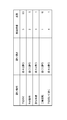
- FIG. 13 A configuration example of a table held by the operation definition unit 1301 is shown in FIG.
- the table shown in FIG. 13 newly adds “walk downward” as a drunken motion to the table shown in FIG. 9 and adds “drunkenly” as the corresponding drunkiness.
- the detection order with respect to each drunk motion is changed from FIG.
- the operation of the determination unit 1302 is the same. That is, it is determined in the order of detection whether the motion of the head of the HMD user based on the position and orientation, the angular velocity, and the acceleration received from the calculation unit 1212 corresponds to which drunken operation in FIG.
- the HMD 1101 differs from the first embodiment in that the following processing is performed in each of step S1702 and step S1705 in the flowchart of FIG. 7.
- the posture sensor unit 1203 acquires the posture information, acceleration, and angular velocity of itself.
- the calculating unit 1212 obtains the position of the imaging unit 1202 from the image captured by the imaging unit 1202, obtains the attitude of the imaging unit 1202 from the attitude information by the attitude sensor unit 1203, and determines the position and attitude of the imaging unit 1202 via the communication unit 1204. It is transmitted to the image processing apparatus 1104.
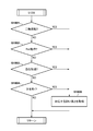
- step S1705 the process according to the flowchart of FIG. 14 is performed.
- Steps S1801 to S1804 differ from the first embodiment in that the table of FIG. 13 is used instead of the table of FIG.
- step S1803 determines in step S1803 that a part or all of the measurement result of the posture sensor unit 1203 does not satisfy the condition corresponding to the intoxication operation "sudden acceleration"
- the process proceeds to step S2401.
- step S 2401 the determination unit 1302 determines whether or not part or all of the position, orientation, acceleration, and angular velocity acquired from the calculation unit 1212 have the detection order “4” in the table of FIG. 13 held by the operation definition unit 1301. It is determined whether or not the condition that corresponds to “turning down and walking” is satisfied.
- step S1805 the determination unit 1302 determines that the motion of the lower part of the table shown in FIG. 13 in which part or all of the measurement results acquired by the posture sensor unit 1203 are held by the operation definition unit 1301 is “5”. It is determined whether the condition corresponding to "turn on" is satisfied.
- the score unit 2501 holds a table holding scores in addition to ease of drunkenness and detection order for each drunk operation.
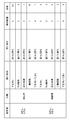
- a configuration example of the table held by the score unit 2501 is shown in FIG.
- the table shown in FIG. 16 is obtained by adding the item of points to the table of FIG. 13, and the points corresponding to each intoxicating operation are registered.
- “0.5” is used as the score for the drunk motion “down”, “roll”, “rapid acceleration”, “biaxial rotation”, and “walk down”.
- “5”, “1”, “10” and “1” are registered.
- the determination unit 1302 acquires a score corresponding to the drunk motion and accumulates the obtained scores. Then, when the sum (cumulative score) of the accumulated points becomes equal to or more than a specified value, the determination unit 1302 outputs character information and voice data to notify a warning. After the notification of the warning, the determination unit 1302 initializes the cumulative score to 0. Note that the cumulative score is initialized to 0 also when the HMD 1101 is started.
- the motion of the HMD 1101 is determined to be normal operation until time t, and when it is determined that the motion of the HMD 1101 is a drunken motion “Roll operation” at time t, the table of FIG. The corresponding score "5" is obtained from. The sum of points accumulated at this point (cumulative point) is “5”. Thereafter, when it is determined that the motion of the HMD 1101 is a drunken motion "sudden acceleration" at time (t + 1), the corresponding score "1" is acquired from the table of FIG. 16 and the cumulative score is "6" at this time. It becomes.
- the cumulative score is "9".
- the corresponding score "1" is acquired from the table of FIG. 16 and the cumulative score is "10".
- the determination unit 1302 outputs character information and voice data to notify a warning.
- times t, (t + 1), (t + 2),... Do not represent adjacent discrete times, but represent timings when it is determined that the motion of the HMD 1101 corresponds to any intoxicating operation.
- step S1702 is different from the first embodiment in the following points in the flowchart of FIG.
- step S1705 the process according to the flowchart of FIG. 18 is performed.
- step S2805 the determination unit 1302 acquires and accumulates the score corresponding to the intoxication operation corresponding to the movement of the HMD 1101 (head). Then, the determination unit 1302 determines that the motion of the HMD 1101 (head) is not a normal operation if the cumulative score is equal to or greater than the specified value, and the motion of the HMD 1101 (head) is determined if the cumulative score is less than the specified value. It is determined that the normal operation is performed. Then, the process proceeds to step S1706.
- steps S1708 and S1709 are deleted from the flowchart of FIG. 7, and when the movement of the HMD 1101 (head) is not the normal operation, the process proceeds to step S1710 via step S1706.
- one type of warning message is stored in the holding unit 1303. Therefore, in step S1710 according to the present embodiment, the determining unit 1302 acquires this message from the holding unit 1303 and superimposes the message. Send to the part 1304.
- the alert is notified according to the movement of the head of the HMD user.
- the points described in the third embodiment are managed for each user or for each user attribute. Then, for the calculation of the cumulative points, the points corresponding to the HMD user are used. In the following, differences from the third embodiment will be described.
- the configuration of FIG. 19 is obtained by adding an authentication unit 2901 to the configuration of the HMD 1101 of FIG.
- the authentication unit 2901 is for identifying a user who wears the HMD 1101, and any configuration may be adopted as long as the configuration is possible.
- the authentication unit 2901 may uniquely identify the user by authenticating the user's iris or fingerprint.
- the HMD 1101 is provided with an operation unit that allows the user to input his / her user ID and password, and the authentication unit 2901 authenticates the user ID and password input by the user operating the operation unit. The user may be uniquely identified.
- the authentication unit 2901 identifies the user before the user wearing the HMD 1101 uses the HMD 1101. Then, the authentication unit 2901 transmits information (user information) unique to the identified user to the operation determination unit 1205.
- An exemplary functional configuration of the operation determination unit 1205 will be described using the block diagram of FIG. In the configuration of FIG. 20, the output (user information) from the authentication unit 2901 is input to the determination unit 1302 in the configuration of FIG. 15, and a score unit 3001 is provided instead of the score unit 2501.
- the score unit 3001 holds, for each user, a “table for managing intoxication, detection order, and score for each intoxication operation” as illustrated in FIG. 16.
- maintains is shown to FIG. 21A.
- the table in FIG. 21A is an example of a table in which a drunk operation, drunk feeling, detection order, and points are managed for each user (user).
- the table manages the intoxication action, intoxication, detection order, score for the user "Mr. A”, intoxication action for the user "Mr. B", intoxication, detection order, points, .
- “Mr. A” is defined as “Sudden movement” and “Two-axis rotation” with higher scores than “Mr. B”, and “Walking down” is defined with lower scores. ing. In other words, this indicates that "Ms. A” is less likely to get drunk than "Ms. B” than "Ms. A”, and "Ms. B” is “sit facing downwards” than “A”. The action shows that it is easy to get drunk.
- the score unit 3001 may hold the table of FIG. 21B instead of the table of FIG. 21A.
- the table manages “Mr. A” and “Mr. C” as a “beginner”, and manages “Ms. B” and “D” as an “experienced person”.
- this table manages the intoxication operation for the "beginner”, the intoxication degree, the detection order, the score, the intoxication operation for the "experienced person”, the intoxication degree, the detection order, and the score.
- the experienced person is less likely to get drunk, so in the example of FIG. 21B, the experienced person has a lower score. In this way, depending on the user's attributes, such as whether the user is a beginner or an experienced person, a set of intoxication, intoxication, detection order, and points may be managed.
- the score unit 3001 may hold both the table of FIG. 21A and the table of FIG. 21B, and the determination unit 1302 may use one of the tables selected by the user operating the operation device 1105. .
- the authentication unit 2901 obtains the user information of the HMD user and sends it to the operation determination unit 1205 before the start of the process according to the flowchart of FIG. 7.
- step S1702 in the flowchart of FIG. 7 processing similar to step S1702 according to the second embodiment is performed, and in step S1705, the determination unit 1302 performs processing according to the flowchart in FIG.
- step S2805 the determination unit 1302 acquires and accumulates the score corresponding to the combination of the user indicated by the user information and the intoxication operation corresponding to the movement of the HMD 1101 (head).
- the determination unit 1302 determines that the motion of the HMD 1101 (head) is not a normal operation if the cumulative score is equal to or greater than the specified value, and the motion of the HMD 1101 (head) is determined if the cumulative score is less than the specified value. It is determined that the normal operation is performed. Then, the process proceeds to step S1706.
- the present invention supplies a program that implements one or more functions of the above-described embodiments to a system or apparatus via a network or storage medium, and one or more processors in a computer of the system or apparatus read and execute the program. Can also be realized. It can also be implemented by a circuit (eg, an ASIC) that implements one or more functions.
- a circuit eg, an ASIC
- imaging unit 1203 attitude sensor unit 1205: operation determination unit 1207: control unit 1208: display unit 1208: voice output unit
Priority Applications (4)
| Application Number | Priority Date | Filing Date | Title |
|---|---|---|---|
| GB2008184.0A GB2582106B (en) | 2017-11-02 | 2018-09-26 | Display device and display device control method |
| CN201880069813.2A CN111279410B (zh) | 2017-11-02 | 2018-09-26 | 显示设备和显示设备控制方法 |
| DE112018005224.9T DE112018005224T5 (de) | 2017-11-02 | 2018-09-26 | Anzeigevorrichtung und Anzeigevorrichtungssteuerverfahren |
| US16/842,836 US11474595B2 (en) | 2017-11-02 | 2020-04-08 | Display device and display device control method |
Applications Claiming Priority (2)
| Application Number | Priority Date | Filing Date | Title |
|---|---|---|---|
| JP2017-213224 | 2017-11-02 | ||
| JP2017213224A JP6934806B2 (ja) | 2017-11-02 | 2017-11-02 | 表示装置、表示装置の制御方法 |
Related Child Applications (1)
| Application Number | Title | Priority Date | Filing Date |
|---|---|---|---|
| US16/842,836 Continuation US11474595B2 (en) | 2017-11-02 | 2020-04-08 | Display device and display device control method |
Publications (1)
| Publication Number | Publication Date |
|---|---|
| WO2019087623A1 true WO2019087623A1 (ja) | 2019-05-09 |
Family
ID=66331669
Family Applications (1)
| Application Number | Title | Priority Date | Filing Date |
|---|---|---|---|
| PCT/JP2018/035692 WO2019087623A1 (ja) | 2017-11-02 | 2018-09-26 | 表示装置、表示装置の制御方法 |
Country Status (6)
| Country | Link |
|---|---|
| US (1) | US11474595B2 (zh) |
| JP (2) | JP6934806B2 (zh) |
| CN (1) | CN111279410B (zh) |
| DE (1) | DE112018005224T5 (zh) |
| GB (1) | GB2582106B (zh) |
| WO (1) | WO2019087623A1 (zh) |
Families Citing this family (2)
| Publication number | Priority date | Publication date | Assignee | Title |
|---|---|---|---|---|
| JP6934806B2 (ja) | 2017-11-02 | 2021-09-15 | キヤノン株式会社 | 表示装置、表示装置の制御方法 |
| JP7467094B2 (ja) | 2019-12-09 | 2024-04-15 | キヤノン株式会社 | 情報処理装置、情報処理方法、及びプログラム |
Citations (5)
| Publication number | Priority date | Publication date | Assignee | Title |
|---|---|---|---|---|
| JP2000339490A (ja) * | 1999-05-28 | 2000-12-08 | Mitsubishi Electric Corp | Vr酔い低減方法 |
| JP2003185967A (ja) * | 2001-12-20 | 2003-07-03 | Olympus Optical Co Ltd | 映像表示装置 |
| WO2016017245A1 (ja) * | 2014-07-31 | 2016-02-04 | ソニー株式会社 | 情報処理装置及び情報処理方法、並びに画像表示システム |
| US20160228771A1 (en) * | 2015-02-05 | 2016-08-11 | Sony Computer Entertainment Inc. | Motion sickness monitoring and application of supplemental sound to counteract sickness |
| JP2017054457A (ja) * | 2015-09-11 | 2017-03-16 | 株式会社コーエーテクモゲームス | 情報処理装置、表示制御方法、及び表示制御プログラム |
Family Cites Families (19)
| Publication number | Priority date | Publication date | Assignee | Title |
|---|---|---|---|---|
| CH674800A5 (zh) | 1986-03-12 | 1990-07-31 | Warner Lambert Co | |
| CN100478849C (zh) * | 2007-04-10 | 2009-04-15 | 南京航空航天大学 | 基于多加速度传感器的虚拟现实头盔防眩晕系统及方法 |
| JP5303685B2 (ja) | 2010-11-09 | 2013-10-02 | 富士フイルム株式会社 | 拡張現実感提供装置 |
| US8831278B2 (en) * | 2010-11-30 | 2014-09-09 | Eastman Kodak Company | Method of identifying motion sickness |
| JP5414946B2 (ja) | 2011-06-16 | 2014-02-12 | パナソニック株式会社 | ヘッドマウントディスプレイおよびその位置ずれ調整方法 |
| US20140176296A1 (en) * | 2012-12-19 | 2014-06-26 | HeadsUp Technologies, Inc. | Methods and systems for managing motion sickness |
| JP6397243B2 (ja) | 2014-07-22 | 2018-09-26 | キヤノン株式会社 | 表示装置、制御方法、及びプログラム |
| JP2016031439A (ja) | 2014-07-28 | 2016-03-07 | ソニー株式会社 | 情報処理装置及び情報処理方法、コンピューター・プログラム、並びに画像表示システム |
| KR101700767B1 (ko) * | 2015-06-02 | 2017-01-31 | 엘지전자 주식회사 | 헤드 마운티드 디스플레이 |
| EP3888958B1 (en) * | 2015-06-03 | 2023-05-24 | ClearMotion, Inc. | Method of mitigating motion sickness in an autonomous vehicle |
| CN105204642B (zh) * | 2015-09-24 | 2018-07-06 | 小米科技有限责任公司 | 虚拟现实交互画面的调节方法和装置 |
| JP2017079389A (ja) * | 2015-10-20 | 2017-04-27 | セイコーエプソン株式会社 | 表示装置、表示装置の制御方法、及び、プログラム |
| KR20170051013A (ko) * | 2015-11-02 | 2017-05-11 | 엘지전자 주식회사 | 테더링 형 hmd 및 그 hmd의 제어 방법 |
| JP2017059196A (ja) | 2015-12-22 | 2017-03-23 | 株式会社コロプラ | 仮想現実空間映像表示方法、及び、プログラム |
| US10388071B2 (en) * | 2016-03-25 | 2019-08-20 | Sony Interactive Entertainment Inc. | Virtual reality (VR) cadence profile adjustments for navigating VR users in VR environments |
| JP6214105B1 (ja) | 2016-05-31 | 2017-10-18 | 株式会社大一商会 | 遊技機 |
| CN106339084A (zh) * | 2016-08-21 | 2017-01-18 | 乐视控股(北京)有限公司 | 虚拟现实设备的控制方法及系统 |
| US10565777B2 (en) * | 2016-09-30 | 2020-02-18 | Sony Interactive Entertainment Inc. | Field of view (FOV) throttling of virtual reality (VR) content in a head mounted display |
| JP6934806B2 (ja) | 2017-11-02 | 2021-09-15 | キヤノン株式会社 | 表示装置、表示装置の制御方法 |
-
2017
- 2017-11-02 JP JP2017213224A patent/JP6934806B2/ja active Active
-
2018
- 2018-09-26 CN CN201880069813.2A patent/CN111279410B/zh active Active
- 2018-09-26 GB GB2008184.0A patent/GB2582106B/en active Active
- 2018-09-26 DE DE112018005224.9T patent/DE112018005224T5/de active Pending
- 2018-09-26 WO PCT/JP2018/035692 patent/WO2019087623A1/ja active Application Filing
-
2020
- 2020-04-08 US US16/842,836 patent/US11474595B2/en active Active
-
2021
- 2021-08-25 JP JP2021137366A patent/JP2022000697A/ja not_active Withdrawn
Patent Citations (5)
| Publication number | Priority date | Publication date | Assignee | Title |
|---|---|---|---|---|
| JP2000339490A (ja) * | 1999-05-28 | 2000-12-08 | Mitsubishi Electric Corp | Vr酔い低減方法 |
| JP2003185967A (ja) * | 2001-12-20 | 2003-07-03 | Olympus Optical Co Ltd | 映像表示装置 |
| WO2016017245A1 (ja) * | 2014-07-31 | 2016-02-04 | ソニー株式会社 | 情報処理装置及び情報処理方法、並びに画像表示システム |
| US20160228771A1 (en) * | 2015-02-05 | 2016-08-11 | Sony Computer Entertainment Inc. | Motion sickness monitoring and application of supplemental sound to counteract sickness |
| JP2017054457A (ja) * | 2015-09-11 | 2017-03-16 | 株式会社コーエーテクモゲームス | 情報処理装置、表示制御方法、及び表示制御プログラム |
Also Published As
| Publication number | Publication date |
|---|---|
| DE112018005224T5 (de) | 2020-07-16 |
| GB2582106B (en) | 2022-12-14 |
| GB2582106A (en) | 2020-09-09 |
| JP6934806B2 (ja) | 2021-09-15 |
| GB202008184D0 (en) | 2020-07-15 |
| US20200241633A1 (en) | 2020-07-30 |
| CN111279410A (zh) | 2020-06-12 |
| JP2022000697A (ja) | 2022-01-04 |
| CN111279410B (zh) | 2022-10-11 |
| JP2019086592A (ja) | 2019-06-06 |
| US11474595B2 (en) | 2022-10-18 |
Similar Documents
| Publication | Publication Date | Title |
|---|---|---|
| JP6316387B2 (ja) | 広範囲同時遠隔ディジタル提示世界 | |
| JP6087453B1 (ja) | 仮想空間の提供方法、およびプログラム | |
| TW202136969A (zh) | 用於在hmd環境中利用傳至gpu之預測及後期更新的眼睛追蹤進行快速注視點渲染的方法及系統以及非暫時性電腦可讀媒體 | |
| US11865448B2 (en) | Information processing apparatus and user guide presentation method | |
| JP5869712B1 (ja) | 没入型仮想空間に実空間のユーザの周辺環境を提示するためのヘッドマウント・ディスプレイ・システムおよびコンピュータ・プログラム | |
| JP2015095802A (ja) | 表示制御装置、表示制御方法、およびプログラム | |
| US11609428B2 (en) | Information processing apparatus and information processing method | |
| JP6312512B2 (ja) | 遠隔見守りシステム | |
| JP2017138973A (ja) | 仮想空間の提供方法、およびプログラム | |
| JP2022000697A (ja) | 表示装置、表示装置の制御方法 | |
| JP2009169622A (ja) | 画像処理装置、画像処理方法 | |
| JP6212666B1 (ja) | 情報処理方法、プログラム、仮想空間配信システム及び装置 | |
| JP2024050696A (ja) | 情報処理装置、ユーザガイド提示方法、およびヘッドマウントディスプレイ | |
| JP6655751B1 (ja) | 映像表示制御装置、方法およびプログラム | |
| JP6739254B2 (ja) | プログラム、情報処理装置、情報処理方法、及びサーバ装置 | |
| WO2017163647A1 (ja) | 頭部装着装置 | |
| JP6738308B2 (ja) | 情報処理方法、プログラム、仮想空間配信システム及び装置 | |
| JP2023096844A (ja) | プログラム、情報処理方法、及び情報処理装置 | |
| JP2022184456A (ja) | 画像処理装置、画像処理方法、及びプログラム | |
| JP2018190078A (ja) | コンテンツ表示プログラム、コンピュータ装置、コンテンツ表示方法、及びコンテンツ表示システム | |
| JP2019135600A (ja) | 表示制御装置、表示制御方法及びプログラム | |
| TW201818193A (zh) | 在虛擬實境中快速移動的方法、虛擬實境裝置及記錄媒體 |
Legal Events
| Date | Code | Title | Description |
|---|---|---|---|
| 121 | Ep: the epo has been informed by wipo that ep was designated in this application |
Ref document number: 18873906 Country of ref document: EP Kind code of ref document: A1 |
|
| ENP | Entry into the national phase |
Ref document number: 202008184 Country of ref document: GB Kind code of ref document: A Free format text: PCT FILING DATE = 20180926 |
|
| 122 | Ep: pct application non-entry in european phase |
Ref document number: 18873906 Country of ref document: EP Kind code of ref document: A1 |