WO2019082931A1 - Powder processing device - Google Patents
Powder processing deviceInfo
- Publication number
- WO2019082931A1 WO2019082931A1 PCT/JP2018/039504 JP2018039504W WO2019082931A1 WO 2019082931 A1 WO2019082931 A1 WO 2019082931A1 JP 2018039504 W JP2018039504 W JP 2018039504W WO 2019082931 A1 WO2019082931 A1 WO 2019082931A1
- Authority
- WO
- WIPO (PCT)
- Prior art keywords
- air flow
- housing
- processing apparatus
- powder processing
- rotating body
- Prior art date
Links
Images


Classifications
-
- B—PERFORMING OPERATIONS; TRANSPORTING
- B02—CRUSHING, PULVERISING, OR DISINTEGRATING; PREPARATORY TREATMENT OF GRAIN FOR MILLING
- B02C—CRUSHING, PULVERISING, OR DISINTEGRATING IN GENERAL; MILLING GRAIN
- B02C23/00—Auxiliary methods or auxiliary devices or accessories specially adapted for crushing or disintegrating not provided for in preceding groups or not specially adapted to apparatus covered by a single preceding group
- B02C23/08—Separating or sorting of material, associated with crushing or disintegrating
- B02C23/10—Separating or sorting of material, associated with crushing or disintegrating with separator arranged in discharge path of crushing or disintegrating zone
- B02C23/12—Separating or sorting of material, associated with crushing or disintegrating with separator arranged in discharge path of crushing or disintegrating zone with return of oversize material to crushing or disintegrating zone
-
- B—PERFORMING OPERATIONS; TRANSPORTING
- B02—CRUSHING, PULVERISING, OR DISINTEGRATING; PREPARATORY TREATMENT OF GRAIN FOR MILLING
- B02C—CRUSHING, PULVERISING, OR DISINTEGRATING IN GENERAL; MILLING GRAIN
- B02C13/00—Disintegrating by mills having rotary beater elements ; Hammer mills
- B02C13/14—Disintegrating by mills having rotary beater elements ; Hammer mills with vertical rotor shaft, e.g. combined with sifting devices
- B02C13/18—Disintegrating by mills having rotary beater elements ; Hammer mills with vertical rotor shaft, e.g. combined with sifting devices with beaters rigidly connected to the rotor
-
- B—PERFORMING OPERATIONS; TRANSPORTING
- B02—CRUSHING, PULVERISING, OR DISINTEGRATING; PREPARATORY TREATMENT OF GRAIN FOR MILLING
- B02C—CRUSHING, PULVERISING, OR DISINTEGRATING IN GENERAL; MILLING GRAIN
- B02C13/00—Disintegrating by mills having rotary beater elements ; Hammer mills
- B02C13/26—Details
- B02C13/28—Shape or construction of beater elements
- B02C13/2804—Shape or construction of beater elements the beater elements being rigidly connected to the rotor
-
- B—PERFORMING OPERATIONS; TRANSPORTING
- B02—CRUSHING, PULVERISING, OR DISINTEGRATING; PREPARATORY TREATMENT OF GRAIN FOR MILLING
- B02C—CRUSHING, PULVERISING, OR DISINTEGRATING IN GENERAL; MILLING GRAIN
- B02C13/00—Disintegrating by mills having rotary beater elements ; Hammer mills
- B02C13/26—Details
- B02C13/282—Shape or inner surface of mill-housings
-
- B—PERFORMING OPERATIONS; TRANSPORTING
- B02—CRUSHING, PULVERISING, OR DISINTEGRATING; PREPARATORY TREATMENT OF GRAIN FOR MILLING
- B02C—CRUSHING, PULVERISING, OR DISINTEGRATING IN GENERAL; MILLING GRAIN
- B02C13/00—Disintegrating by mills having rotary beater elements ; Hammer mills
- B02C13/26—Details
- B02C13/288—Ventilating, or influencing air circulation
-
- B—PERFORMING OPERATIONS; TRANSPORTING
- B02—CRUSHING, PULVERISING, OR DISINTEGRATING; PREPARATORY TREATMENT OF GRAIN FOR MILLING
- B02C—CRUSHING, PULVERISING, OR DISINTEGRATING IN GENERAL; MILLING GRAIN
- B02C15/00—Disintegrating by milling members in the form of rollers or balls co-operating with rings or discs
-
- B—PERFORMING OPERATIONS; TRANSPORTING
- B02—CRUSHING, PULVERISING, OR DISINTEGRATING; PREPARATORY TREATMENT OF GRAIN FOR MILLING
- B02C—CRUSHING, PULVERISING, OR DISINTEGRATING IN GENERAL; MILLING GRAIN
- B02C23/00—Auxiliary methods or auxiliary devices or accessories specially adapted for crushing or disintegrating not provided for in preceding groups or not specially adapted to apparatus covered by a single preceding group
- B02C23/08—Separating or sorting of material, associated with crushing or disintegrating
- B02C23/10—Separating or sorting of material, associated with crushing or disintegrating with separator arranged in discharge path of crushing or disintegrating zone
-
- B—PERFORMING OPERATIONS; TRANSPORTING
- B02—CRUSHING, PULVERISING, OR DISINTEGRATING; PREPARATORY TREATMENT OF GRAIN FOR MILLING
- B02C—CRUSHING, PULVERISING, OR DISINTEGRATING IN GENERAL; MILLING GRAIN
- B02C23/00—Auxiliary methods or auxiliary devices or accessories specially adapted for crushing or disintegrating not provided for in preceding groups or not specially adapted to apparatus covered by a single preceding group
- B02C23/18—Adding fluid, other than for crushing or disintegrating by fluid energy
- B02C23/24—Passing gas through crushing or disintegrating zone
- B02C23/30—Passing gas through crushing or disintegrating zone the applied gas acting to effect material separation
Landscapes
- Engineering & Computer Science (AREA)
- Food Science & Technology (AREA)
- Crushing And Pulverization Processes (AREA)
Abstract
To achieve lower air flow rate and finer powder with a simple constitution, a powder processing device is provided with: a cylindrical housing; a raw material supply unit; a first rotating body that rotates around a center axis; a pulverizing member for pulverizing the raw material; a second rotating body that rotates around the center axis; a plurality of blades that are disposed in a radial pattern at one end in a direction perpendicular to the second rotating body; an air inflow unit that is disposed at the lower side of the rotating body and allows inflow of an air flow to the inside of the housing; an air outflow unit for discharging the air flow, including powder, from the top of the housing; and a guide surface that faces the second rotating body in the radial direction and the front side of which is positioned more to the inside in the radial direction than the back side in the direction of rotation of the second rotating body.
Description
本発明は、塊状の原料を粉砕して所定の粒径の粉粒体を生成する粉体処理装置に関する。
BACKGROUND OF THE INVENTION Field of the Invention The present invention relates to a powder processing apparatus for pulverizing massive raw materials to produce powder particles having a predetermined particle diameter.
従来の微粉砕装置は、特開2001-259451号公報に開示されている。この微粉砕装置は、粉砕室の内部に回転自在に設けられた粉砕ロータと、粉砕ロータの外周部との間に隙間をあけて配置されたライナと、所定粒度以下のものを外部に排出する分級ロータと、分級ロータで排出されない原料を下方に案内する循環通路と、粉砕室の内面から内側に突出し原料を衝突させて分級ロータで排出されない原料が粉砕室の内面に沿って旋回するのを抑制するベーンを備えている。
A conventional pulverizing apparatus is disclosed in JP-A-2001-259451. This comminution device discharges to the outside a comminution rotor, which is rotatably provided inside the comminution chamber, a liner which is disposed with a gap between the circumference of the comminution rotor, and which has a predetermined particle size or less. The classification rotor, the circulation passage for guiding the raw material not discharged by the classification rotor downward, and the raw material protruding inward from the inner surface of the grinding chamber to collide with the raw material not discharged by the classification rotor swirl along the inner surface of the grinding chamber It has a vane to suppress.
この微粉砕装置では、投入された原料は、粉砕ロータとライナとによって粉砕される。そして、粉砕された原料は、内部に導かれる気流によって上方に移動し、分級ロータで遠心力が付与される。気流による内側向きの力が遠心力よりも大きくなる所定粒度よりも小さい粒度の原料は、外部に排出される。外部に排出されない原料、すなわち、所定粒度よりも大きい粒度の原料は、粉砕室に沿って周方向に流れるが、ベーンと衝突して、落下し、粉砕ロータとライナと再度粉砕される。このように、ベーンを備えることで、粉砕ロータ上に大量の原料が、一気に落下することなく、粉砕ロータの脈動を防止し、粉砕ロータを安定駆動できる。
In this comminution device, the input material is comminuted by the comminution rotor and liner. Then, the pulverized raw material is moved upward by the air flow introduced to the inside, and a centrifugal force is applied by the classification rotor. The raw material of the particle size smaller than the predetermined particle size where the inward force by the air flow becomes larger than the centrifugal force is discharged to the outside. The raw material that is not discharged to the outside, that is, the raw material having a particle size larger than the predetermined particle size flows circumferentially along the grinding chamber, but collides with the vane and falls to be ground again with the grinding rotor and liner. As described above, by providing the vanes, it is possible to prevent the pulsation of the grinding rotor and stably drive the grinding rotor without a large amount of raw material falling on the grinding rotor at a stroke.
しかしながら、特開2001-259451号公報の微粉砕装置では、分級ロータによって発生した気流もベーンに衝突する。ベーンに衝突した気流は、上下方向に流れる。このとき、下方に流れる気流は、粉砕ロータとライナーとの隙間から分級ロータに向かって流れる気流と衝突するため、分級ロータに向かって流れる気流の流速、すなわち、エネルギが弱くなる。そのため、特開2001-259451号公報の微粉砕装置では、分級ロータに向かって流れる気流の流量を、ベーンに衝突した気流が吹き付けられても、上方に向かって流れることができる流量とする必要がある。そして、分級ロータによって分級される粉粒体の粒度は、分級ロータの回転数に反比例し、分級ロータに流れる気流の流量の平方根に比例する。特開2001-259451号公報の微粉砕装置では、分級ロータに流れる気流の流量を小さくするのが困難であるため、分級される粉粒体を一定の粒度以下にするのは困難である。
However, in the pulverizing apparatus of JP-A-2001-259451, the air flow generated by the classification rotor also collides with the vanes. The air stream that has collided with the vanes flows vertically. At this time, since the air flow flowing downward collides with the air flow flowing toward the classification rotor from the gap between the grinding rotor and the liner, the flow velocity of the air flow flowing toward the classification rotor, that is, the energy becomes weak. Therefore, in the pulverizing apparatus of JP-A-2001-259451, it is necessary to set the flow rate of the air flow flowing toward the classification rotor to a flow rate that can flow upward even if the air flow colliding with the vane is blown. is there. Then, the particle size of the powder particles classified by the classification rotor is inversely proportional to the number of rotations of the classification rotor and proportional to the square root of the flow rate of the air flow flowing to the classification rotor. In the pulverizing apparatus disclosed in JP-A-2001-259451, it is difficult to reduce the flow rate of the air flowing through the classification rotor, and therefore, it is difficult to make the particles to be classified smaller than a certain particle size.
そこで、本発明は上記のような課題を解決するためになされたものであり、簡単な構成を有するとともに気流の低流量化及び粉粒体の微細化ができる粉体処理装置を提供することを目的とする。
Therefore, the present invention has been made to solve the above-described problems, and it is an object of the present invention to provide a powder processing apparatus having a simple configuration and capable of reducing the flow rate of air flow and miniaturizing powder particles. To aim.
上記目的を達成するため本発明にかかる粉体処理装置は、鉛直方向に延びる筒状の筐体と、前記筐体内に原料を供給する原料供給部と、前記原料供給部の下側に配置されて鉛直方向に延びる中心軸周りに回転する第1回転体と、前記第1回転体の径方向外縁部に配置されて前記原料を粉粒体に粉砕する粉砕部材と、前記筐体内において前記第1回転体の上側に配置されて前記筐体内に旋回方向の気流を発生させる旋回気流発生部と、前記筐体の前記回転体の下側に配置されて前記筐体内に気流を流入させる気流流入部と、前記筐体の上部から前記気流を流出させる気流流出部と、を備え、前記筐体の内部には、前記旋回気流発生部と径方向に対向するとともに前記旋回気流発生部の回転方向における前側が後側に比べて径方向内側に位置する案内面を有する案内部を備える。
In order to achieve the above object, a powder processing apparatus according to the present invention comprises a cylindrical casing extending in the vertical direction, a raw material supply unit for supplying a raw material into the casing, and a lower side of the raw material supply unit A first rotating body that rotates about a central axis extending in the vertical direction, a crushing member disposed at a radial outer edge of the first rotating body, and crushing the raw material into powder particles; A swirling air flow generation unit disposed above the one rotation body and generating an air flow in the turning direction in the housing, and an air flow inflow arranged in the housing below the rotation body of the housing and flowing the air flow into the housing And an air flow outflow portion for flowing out the air flow from the upper portion of the housing, and inside the housing, the air flow outflow portion radially faces the swirl air flow generation portion and the rotational direction of the swirl air flow generation portion Located inward in the radial direction compared to the rear Comprising a guide portion having a guide surface.
この構成によると、案内面によって筐体内部を旋回する粉粒体に径方向内側に向かう力を付与している。そのため、気流流入部から流入する気流の流量を少なくしても、粉粒体を径方向内側に押す力を付与させることが可能である。これにより、気流流入部から流入する気流の流量を少なくすることができる。また、気流の流量を少なくできることで、気流流出部から排出される粉粒体の粒径を小さくできる、すなわち、微細化が可能である。また、気流の流量を少なくすることで、気流を発生する装置を小型化することができ、装置全体を小型化できる。さらに気流の流量を少なく抑えることで、消費電力を抑え、省電力化が可能である。
According to this configuration, the radially inward force is applied to the powder or granular material swirling inside the housing by the guide surface. Therefore, even if the flow rate of the air flow inflowing from the air flow inflow portion is reduced, it is possible to apply a force that pushes the granular material inward in the radial direction. Thereby, the flow rate of the air flow inflowing from the air flow inflow portion can be reduced. In addition, since the flow rate of the air flow can be reduced, the particle size of the powder particles discharged from the air flow outflow portion can be reduced, that is, miniaturization can be performed. Further, by reducing the flow rate of the air flow, the device for generating the air flow can be miniaturized, and the entire device can be miniaturized. Furthermore, by reducing the flow rate of the air flow, it is possible to reduce power consumption and save power.
上記構成において、前記旋回気流発生部は、中心軸周りに回転する第2回転体と、前記第2回転体の周部に放射状に立設された複数枚のブレードと、を備えてもよい。このように構成することで、粉粒体の分級を簡単な構成で行うことが可能である。
In the above configuration, the swirling air flow generation unit may include a second rotating body that rotates around a central axis, and a plurality of blades that are radially provided around the periphery of the second rotating body. With such a configuration, classification of powder particles can be performed with a simple configuration.
上記構成において、前記案内面の前記旋回気流発生部の回転方向における前側の端部から周方向に延長した面は、前記旋回気流発生部よりも径方向外側に位置する。このように構成することで、案内面で案内された気流が旋回気流発生部から粉粒体に付与される遠心力を邪魔しにくい。また、粉粒体が、旋回気流発生部に衝突するのを抑制できる。
In the above configuration, a surface of the guide surface, which is circumferentially extended from an end portion on the front side in the rotational direction of the swirling airflow generating portion, is positioned radially outward of the swirling airflow generating portion. With this configuration, the air flow guided by the guide surface is less likely to disturb the centrifugal force applied to the granular material from the swirling air flow generation unit. Moreover, it can suppress that a granular material collides with a turning airflow generation part.
上記構成において、前記筐体は、前記中心軸に沿って延びる筒状のハウジング筒部を、備え、前記案内部の少なくとも一つは、前記ハウジング筒部から径方向内側に延びる。このように構成することで、案内部をしっかり固定することが可能である。
In the above configuration, the housing includes a cylindrical housing cylinder extending along the central axis, and at least one of the guides extends radially inward from the housing cylinder. With this configuration, it is possible to fix the guide firmly.
上記構成において、前記筐体は、鉛直方向上端部に、中心軸と直交する方向に拡がるハウジング天板部を、備え、前記案内部の少なくとも一つは、前記ハウジング天板部の下面から下方に延びる。このように構成することで、案内部をしっかり固定することが可能である。また、ハウジング天板部と共に、案内部を取り出すことができるので、メンテナンスが容易である。
In the above configuration, the housing includes a housing top plate at an upper end in the vertical direction and extending in a direction perpendicular to the central axis, and at least one of the guides is downward from the lower surface of the housing top plate. Extend. With this configuration, it is possible to fix the guide firmly. In addition, since the guide portion can be taken out together with the housing top plate portion, maintenance is easy.
上記構成において、前記案内部は、板状である。
In the above-mentioned composition, the above-mentioned guidance part is tabular.
上記構成において、前記案内面は、周方向の中間部分が径方向に膨らんだ曲面である。
In the above configuration, the guide surface is a curved surface in which an intermediate portion in the circumferential direction is expanded in the radial direction.
上記構成において、前記案内面は、上側が下側に対して、前記旋回気流発生部の回転方向における前側に位置する。
In the above configuration, the guide surface is located on the front side in the rotation direction of the swirling air flow generating unit with the upper side being lower side.
本発明によると、簡単な構成を有するとともに気流の低流量化及び粉粒体の微細化できる粉体処理装置を提供することができる。
According to the present invention, it is possible to provide a powder processing apparatus that has a simple configuration, can reduce the flow rate of air flow, and can make fine particles.
本発明にかかる粉体処理装置について図面を参照して説明する。
A powder processing apparatus according to the present invention will be described with reference to the drawings.
<1. 粉体処理装置の構成>
図1は、本発明にかかる粉体処理装置の断面図である。粉体処理装置Aは、塊状の材料を粉粒体に破砕処理する。図1に示すように、粉体処理装置Aは、筐体10と、原料供給部20と、駆動部30と、粉砕部40と、旋回気流発生部50と、案内部60と、気流流出部70とを備える。なお、中心軸C1が延びる方向を上下方向とする。上下方向と直交する方向を径方向とし、中心に向う側を内側、中心から離れる側を外側とする。また、中心軸C1を中心とする円周に沿う方向を周方向とする。 <1. Configuration of powder processing apparatus>
FIG. 1 is a cross-sectional view of a powder processing apparatus according to the present invention. The powder processing apparatus A crushes lumped material into powder particles. As shown in FIG. 1, the powder processing apparatus A includes ahousing 10, a raw material supply unit 20, a drive unit 30, a crushing unit 40, a swirling air flow generation unit 50, a guiding unit 60, and an air flow outflow unit. And 70. The direction in which the central axis C1 extends is referred to as the vertical direction. The direction perpendicular to the vertical direction is taken as the radial direction, the side facing the center is taken as the inside, and the side away from the center is taken as the outside. Further, a direction along a circumference centered on the central axis C1 is taken as a circumferential direction.
図1は、本発明にかかる粉体処理装置の断面図である。粉体処理装置Aは、塊状の材料を粉粒体に破砕処理する。図1に示すように、粉体処理装置Aは、筐体10と、原料供給部20と、駆動部30と、粉砕部40と、旋回気流発生部50と、案内部60と、気流流出部70とを備える。なお、中心軸C1が延びる方向を上下方向とする。上下方向と直交する方向を径方向とし、中心に向う側を内側、中心から離れる側を外側とする。また、中心軸C1を中心とする円周に沿う方向を周方向とする。 <1. Configuration of powder processing apparatus>
FIG. 1 is a cross-sectional view of a powder processing apparatus according to the present invention. The powder processing apparatus A crushes lumped material into powder particles. As shown in FIG. 1, the powder processing apparatus A includes a
<1.1 筐体10の構成>
筐体10は、ハウジング11と、軸保持部12と、原料受入孔13と、気流流入部14と、ボトムカバー15と、ヒンジ16と、を備える。ハウジング11は、上下に延びる中心軸C1に沿って延びる円筒状である。 <1.1 Configuration ofCase 10>
Thehousing 10 includes a housing 11, a shaft holding portion 12, a raw material receiving hole 13, an air flow inflow portion 14, a bottom cover 15, and a hinge 16. The housing 11 has a cylindrical shape extending along a central axis C1 extending vertically.
筐体10は、ハウジング11と、軸保持部12と、原料受入孔13と、気流流入部14と、ボトムカバー15と、ヒンジ16と、を備える。ハウジング11は、上下に延びる中心軸C1に沿って延びる円筒状である。 <1.1 Configuration of
The
<1.1.1 ハウジング11の構成>
図1に示すように、ハウジング11は、ハウジング底部111と、ハウジング筒部112と、フランジ部113と、ハウジング天板部114と、を備える。ハウジング底部111は、径方向に中心から外側に拡がる円板状である。ハウジング11は、ハウジング底部111が水平となるように、図示を省略した架台等に固定される。ハウジング筒部112は、ハウジング底部111の外縁部から中心軸C1に沿って上側に向かって延びる筒状である。ハウジング筒部112は、中心軸C1を中心とする円筒状である。 <1.1.1 Configuration ofHousing 11>
As shown in FIG. 1, thehousing 11 includes a housing bottom portion 111, a housing cylindrical portion 112, a flange portion 113, and a housing top plate portion 114. The housing bottom portion 111 is in the form of a disc that radially extends from the center to the outside. The housing 11 is fixed to a rack or the like (not shown) so that the housing bottom 111 is horizontal. The housing cylindrical portion 112 has a cylindrical shape extending upward from the outer edge of the housing bottom 111 along the central axis C1. The housing cylinder portion 112 is cylindrical with the central axis C1 as a center.
図1に示すように、ハウジング11は、ハウジング底部111と、ハウジング筒部112と、フランジ部113と、ハウジング天板部114と、を備える。ハウジング底部111は、径方向に中心から外側に拡がる円板状である。ハウジング11は、ハウジング底部111が水平となるように、図示を省略した架台等に固定される。ハウジング筒部112は、ハウジング底部111の外縁部から中心軸C1に沿って上側に向かって延びる筒状である。ハウジング筒部112は、中心軸C1を中心とする円筒状である。 <1.1.1 Configuration of
As shown in FIG. 1, the
フランジ部113は、ハウジング筒部112の上端に配置され、径方向外側に拡がる。フランジ部113とハウジング筒部112とは、一体成形体である。すなわち、ハウジング底部111、ハウジング筒部112及びフランジ部113は、金属の一体成形体である。なお、金属としては、例えば、ステンレスを挙げることができるが、これに限定されない。
The flange portion 113 is disposed at the upper end of the housing cylindrical portion 112 and spreads radially outward. The flange portion 113 and the housing cylindrical portion 112 are an integrally molded body. That is, the housing bottom portion 111, the housing cylindrical portion 112, and the flange portion 113 are integrally formed of metal. In addition, as a metal, although stainless steel can be mentioned, for example, it is not limited to this.
図1に示すように、ハウジング筒部112の下端部は、ハウジング底部111によって閉じられる。また、ハウジング筒部112の上端部は、開口している。ハウジング天板部114は、ハウジング筒部112の上端部の開口を閉じる。ハウジング天板部114は、フランジ部113にヒンジ16を介して取り付けられる。これにより、ハウジング天板部114は、ヒンジ16の回転軸161を中心に回動し、ハウジング筒部112の開口を開閉する。
As shown in FIG. 1, the lower end portion of the housing cylindrical portion 112 is closed by the housing bottom portion 111. Further, the upper end portion of the housing cylindrical portion 112 is open. The housing top plate portion 114 closes the opening at the upper end portion of the housing cylindrical portion 112. The housing top plate portion 114 is attached to the flange portion 113 via a hinge 16. Thus, the housing top plate 114 pivots about the rotation shaft 161 of the hinge 16 to open and close the opening of the housing cylinder 112.
また、ハウジング筒部112の開口を閉じた状態において、ハウジング天板部114はフランジ部113にねじ等で固定される。これにより、ハウジング筒部112とハウジング天板部114とは、確実に固定されるとともに隙間から気流が漏れないように密閉される。なお、ねじ等による固定は、1箇所であってもよいが、固定及び密閉を確実に行うため、複数箇所で固定されることが好ましい。また、ガスケット、パッキン等を配置して、気密性を高めてもよい。
Further, in a state in which the opening of the housing cylindrical portion 112 is closed, the housing top plate portion 114 is fixed to the flange portion 113 with a screw or the like. Thus, the housing cylindrical portion 112 and the housing top plate portion 114 are securely fixed and sealed so that the air flow does not leak from the gap. In addition, although fixation by a screw etc. may be one place, in order to perform fixation and sealing reliably, it is preferable to be fixed in multiple places. In addition, gaskets, packings, etc. may be arranged to improve the airtightness.
ハウジング底部111の中央部分には、上下に貫通する貫通孔115が形成される。駆動部30の後述する第1シャフト31及び第2シャフト32が、貫通孔115を貫通する。また、ハウジング天板部114の中央部分には、上下に貫通する排出孔116が設けられる。
In the central portion of the housing bottom portion 111, a through hole 115 is formed which penetrates up and down. A first shaft 31 and a second shaft 32, which will be described later, of the drive unit 30 pass through the through hole 115. Further, at a central portion of the housing top plate portion 114, a discharge hole 116 penetrating vertically is provided.
<1.1.2 軸保持部12の構成>
図1に示すように、軸保持部12は、ハウジング底部111の中心部分に配置されて上下に延びる筒状である。軸保持部12は、中心が中心軸C1と一致する。軸保持部12は、ハウジング底部111にねじ等の固定具にて固定される。 <1.1.2 Configuration ofAxis Holder 12>
As shown in FIG. 1, theshaft holding portion 12 has a cylindrical shape which is disposed at the central portion of the housing bottom portion 111 and extends vertically. The center of the axis holding portion 12 coincides with the central axis C1. The shaft holding portion 12 is fixed to the housing bottom portion 111 by a fixing tool such as a screw.
図1に示すように、軸保持部12は、ハウジング底部111の中心部分に配置されて上下に延びる筒状である。軸保持部12は、中心が中心軸C1と一致する。軸保持部12は、ハウジング底部111にねじ等の固定具にて固定される。 <1.1.2 Configuration of
As shown in FIG. 1, the
軸保持部12の上端部には、シール(ここでは、ラビリンスシール)が構成されている。これにより、第1回転体41の回転が妨げられることなく、粉粒体を含む気流の軸保持部12の内部への流入が抑制される。
A seal (here, a labyrinth seal) is formed on the upper end portion of the shaft holding portion 12. In this way, the flow of the air flow including the granular material into the shaft holding portion 12 is suppressed without preventing the rotation of the first rotating body 41.
<1.1.3 原料受入孔13の構成>
原料受入孔13は、原料供給部20から供給される塊状の原料を、ハウジング筒部112、すなわち、筐体10内部に受け入れる。図1に示すように、原料受入孔13は、ハウジング筒部112に設けられ、径方向に貫通する貫通孔である。原料受入孔13は、ハウジング筒部112の内部に配置された、粉砕部40よりも上側に配置される。 <1.1.3 Configuration of RawMaterial Receiving Hole 13>
The rawmaterial receiving hole 13 receives the massive raw material supplied from the raw material supply unit 20 into the housing cylindrical portion 112, that is, the inside of the housing 10. As shown in FIG. 1, the raw material receiving hole 13 is a through hole provided in the housing cylindrical portion 112 and penetrating in the radial direction. The raw material receiving hole 13 is disposed on the upper side of the crushing unit 40 disposed inside the housing cylindrical portion 112.
原料受入孔13は、原料供給部20から供給される塊状の原料を、ハウジング筒部112、すなわち、筐体10内部に受け入れる。図1に示すように、原料受入孔13は、ハウジング筒部112に設けられ、径方向に貫通する貫通孔である。原料受入孔13は、ハウジング筒部112の内部に配置された、粉砕部40よりも上側に配置される。 <1.1.3 Configuration of Raw
The raw
<1.1.4 気流流入部14の構成>
気流流入部14では、ハウジング筒部112の外部から内部に流れ込む気流が供給される。図1に示すように、気流流入部14は、ハウジング筒部112に設けられ、径方向に貫通する貫通孔である。気流流入部14は、粉砕部40よりも下側に配置される。 <1.1.4 Configuration ofAirflow Inflow Unit 14>
In the airflow inlet portion 14, an air flow which flows into the inside from the outside of the housing cylinder portion 112 is supplied. As shown in FIG. 1, the air flow inlet portion 14 is a through hole provided in the housing cylindrical portion 112 and penetrating in the radial direction. The air flow inflow portion 14 is disposed below the crushing portion 40.
気流流入部14では、ハウジング筒部112の外部から内部に流れ込む気流が供給される。図1に示すように、気流流入部14は、ハウジング筒部112に設けられ、径方向に貫通する貫通孔である。気流流入部14は、粉砕部40よりも下側に配置される。 <1.1.4 Configuration of
In the air
<1.1.5 ボトムカバー15の構成>
ボトムカバー15は、ハウジング筒部112の内部において、粉砕部40よりも下側に配置される。ボトムカバー15は円環状である。ボトムカバー15と第1回転体41とは、上下に間隙をあけて対向する。そして、ボトムカバー15の上面と粉砕部40の第1回転体41の下面との間隙に気流が流入する。この気流によって、粉砕部40で粉砕された粉粒体が上側及び内側に搬送される。そのため、気流流入部14から供給される気流を、粉粒体を搬送する搬送気流と称する。 <1.1.5 Configuration ofBottom Cover 15>
Thebottom cover 15 is disposed below the crushing unit 40 inside the housing cylindrical portion 112. The bottom cover 15 is annular. The bottom cover 15 and the first rotating body 41 face each other with a gap at the top and bottom. Then, the air flow flows into the gap between the upper surface of the bottom cover 15 and the lower surface of the first rotating body 41 of the crushing unit 40. By the air flow, the granular material crushed by the crushing unit 40 is conveyed upward and inward. Therefore, the air flow supplied from the air flow in-flow portion 14 is referred to as a transfer air flow for transferring the powder particles.
ボトムカバー15は、ハウジング筒部112の内部において、粉砕部40よりも下側に配置される。ボトムカバー15は円環状である。ボトムカバー15と第1回転体41とは、上下に間隙をあけて対向する。そして、ボトムカバー15の上面と粉砕部40の第1回転体41の下面との間隙に気流が流入する。この気流によって、粉砕部40で粉砕された粉粒体が上側及び内側に搬送される。そのため、気流流入部14から供給される気流を、粉粒体を搬送する搬送気流と称する。 <1.1.5 Configuration of
The
<1.2 原料供給部20の構成>
図1に示すように、原料供給部20は、原料供給管21と、スクリューコンベア22とを備える。原料供給管21は、管体であり、一部が原料受入孔13からハウジング筒部112の内部に挿入されて、固定される。原料供給管21の内部には、スクリューコンベア22が回転可能に配置される。スクリューコンベア22は、回転することで塊状の原料を原料供給管21に沿って移動させる。スクリューコンベア22にて移動された塊状の原料は、原料受入孔13からハウジング筒部112の内部に投入される。なお、スクリューコンベア以外の搬送方法を採用してもよい。 <1.2 Configuration of RawMaterial Supply Unit 20>
As shown in FIG. 1, the rawmaterial supply unit 20 includes a raw material supply pipe 21 and a screw conveyor 22. The raw material supply pipe 21 is a pipe, and a part of the raw material supply pipe 21 is inserted from the raw material receiving hole 13 into the inside of the housing cylindrical portion 112 and fixed. A screw conveyor 22 is rotatably disposed inside the raw material supply pipe 21. The screw conveyor 22 moves the bulk material along the material supply pipe 21 by rotating. The massive raw material moved by the screw conveyor 22 is introduced from the raw material receiving hole 13 into the inside of the housing cylindrical portion 112. In addition, you may employ | adopt conveyance methods other than a screw conveyor.
図1に示すように、原料供給部20は、原料供給管21と、スクリューコンベア22とを備える。原料供給管21は、管体であり、一部が原料受入孔13からハウジング筒部112の内部に挿入されて、固定される。原料供給管21の内部には、スクリューコンベア22が回転可能に配置される。スクリューコンベア22は、回転することで塊状の原料を原料供給管21に沿って移動させる。スクリューコンベア22にて移動された塊状の原料は、原料受入孔13からハウジング筒部112の内部に投入される。なお、スクリューコンベア以外の搬送方法を採用してもよい。 <1.2 Configuration of Raw
As shown in FIG. 1, the raw
<1.3 駆動部30の構成>
駆動部30は、粉砕部40及び旋回気流発生部50を駆動する。図1に示すように、駆動部30は、第1シャフト31と、第2シャフト32と、第1ベルト331と、第2ベルト332と、を備える。 <1.3 Configuration ofDrive Unit 30>
Thedrive unit 30 drives the crushing unit 40 and the swirling air flow generation unit 50. As shown in FIG. 1, the drive unit 30 includes a first shaft 31, a second shaft 32, a first belt 331, and a second belt 332.
駆動部30は、粉砕部40及び旋回気流発生部50を駆動する。図1に示すように、駆動部30は、第1シャフト31と、第2シャフト32と、第1ベルト331と、第2ベルト332と、を備える。 <1.3 Configuration of
The
<1.3.1 第1シャフト31の構成>
第1シャフト31は筒状である。第1シャフト31の上端には、第1回転体41が固定される。第1シャフト31は、軸保持部12の内部に配置された不図示のベアリングを介して回転可能に支持される。第1シャフト31は、軸保持部12に対して、上下方向に支持されるとともに中心軸C1周りに回転可能に支持される。 <1.3.1 Configuration ofFirst Shaft 31>
Thefirst shaft 31 is cylindrical. The first rotating body 41 is fixed to the upper end of the first shaft 31. The first shaft 31 is rotatably supported via a bearing (not shown) disposed inside the shaft holding portion 12. The first shaft 31 is vertically supported by the shaft holding portion 12 and rotatably supported around the central axis C1.
第1シャフト31は筒状である。第1シャフト31の上端には、第1回転体41が固定される。第1シャフト31は、軸保持部12の内部に配置された不図示のベアリングを介して回転可能に支持される。第1シャフト31は、軸保持部12に対して、上下方向に支持されるとともに中心軸C1周りに回転可能に支持される。 <1.3.1 Configuration of
The
第1シャフト31の下端部は、ハウジング底部111の貫通孔115を貫通してハウジング底部111よりも下側に突出する。そして、第1シャフト31の下端部には、第1プーリ311が、第1シャフト31に回り止めされつつ、固定されている。第1プーリ311の固定方法としては、例えば、圧入、溶接、接着等を挙げることができるが、これに限定されない。また、確実に回り止めを行うために、キー及びキー溝を採用してもよい。第1シャフト31の断面形状を円形以外の形状として、回り止めするようにしてもよい。
The lower end portion of the first shaft 31 penetrates the through hole 115 of the housing bottom portion 111 and protrudes below the housing bottom portion 111. The first pulley 311 is fixed to the lower end portion of the first shaft 31 while being locked to the first shaft 31. Examples of the method of fixing the first pulley 311 include, but are not limited to, press fitting, welding, adhesion, and the like. Also, a key and a key groove may be employed in order to securely prevent the rotation. The cross-sectional shape of the first shaft 31 may be a non-circular shape to prevent rotation.
第1プーリ311には、第1ベルト331が巻き回されている。第1ベルト331を介して不図示のモータからの回転力が伝達されて、第1プーリ311が中心軸C1周りに回転する。これにより、第1プーリ311が取り付けられた第1シャフト31及び第1シャフト31に固定された第1回転体41は、中心軸C1周りに回転する。
A first belt 331 is wound around the first pulley 311. The rotational force from a motor (not shown) is transmitted via the first belt 331, and the first pulley 311 rotates around the central axis C1. Accordingly, the first shaft 31 to which the first pulley 311 is attached and the first rotating body 41 fixed to the first shaft 31 rotate around the central axis C1.
<1.3.2 第2シャフト32の構成>
第2シャフト32は、円柱状であり、筒状の第1シャフト31の内部に配置される。第2シャフト32は、不図示のベアリングを介して第1シャフト31に回転可能に支持される。つまり、第2シャフト32は、軸保持部12に中心軸C1周りに回転可能に支持される。 <1.3.2 Configuration ofSecond Shaft 32>
Thesecond shaft 32 is cylindrical and disposed inside the cylindrical first shaft 31. The second shaft 32 is rotatably supported by the first shaft 31 via a bearing (not shown). That is, the second shaft 32 is rotatably supported by the shaft holding portion 12 about the central axis C1.
第2シャフト32は、円柱状であり、筒状の第1シャフト31の内部に配置される。第2シャフト32は、不図示のベアリングを介して第1シャフト31に回転可能に支持される。つまり、第2シャフト32は、軸保持部12に中心軸C1周りに回転可能に支持される。 <1.3.2 Configuration of
The
第2シャフト32の下端部は、第1シャフト31の下端部よりも下側に突出する。そして、第2シャフト32の第1シャフト31の下端部よりも下側に突出した部分には、第2プーリ321が回り止めされつつ、固定されている。第2プーリ321の固定方法としては、例えば、圧入、溶接、接着等を挙げることができるが、これに限定されない。また、確実に回り止めを行うために、キー及びキー溝を採用してもよい。また、第2シャフト32の断面形状を円形以外の形状として、回り止めするようにしてもよい。
The lower end portion of the second shaft 32 protrudes below the lower end portion of the first shaft 31. The second pulley 321 is fixed to a portion of the second shaft 32 that protrudes below the lower end portion of the first shaft 31 while being prevented from rotating. Examples of a method of fixing the second pulley 321 include, but are not limited to, press-fitting, welding, adhesion, and the like. Also, a key and a key groove may be employed in order to securely prevent the rotation. In addition, the cross-sectional shape of the second shaft 32 may be a non-circular shape to prevent rotation.
第2プーリ321には、第2ベルト332が巻き回されている。第2ベルト332を介して不図示のモータからの回転力が伝達されて、第2プーリ321が中心軸C1周りに回転する。これにより、第2プーリ321が取り付けられた第2シャフト32及び第2シャフト32に固定された第2回転体51は、中心軸C1周りに回転する。
A second belt 332 is wound around the second pulley 321. The rotational force from a motor (not shown) is transmitted via the second belt 332, and the second pulley 321 rotates around the central axis C1. As a result, the second shaft 32 to which the second pulley 321 is attached and the second rotating body 51 fixed to the second shaft 32 rotate around the central axis C1.
第1プーリ311及び第2プーリ321は、異なる回転数で回転可能とするため、異なるモータから駆動力が伝達されてもよい。また、減速機を用いることで、共通のモータを用いて、第1プーリ311及び第2プーリ321を異なる回転数で回転させることが可能である。ここで、異なる回転数とは、回転方向が同じ場合を含むとともに、回転方向が異なる場合も含む。
In order to make the first pulley 311 and the second pulley 321 rotatable at different rotational speeds, driving forces may be transmitted from different motors. In addition, by using the reduction gear, it is possible to rotate the first pulley 311 and the second pulley 321 at different rotational speeds using a common motor. Here, different rotation numbers include cases where the rotation direction is the same as well as cases where the rotation direction is different.
<1.4 粉砕部40の構成>
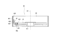
粉砕部40は、原料供給部20よりも下側に配置される。そして、粉砕部40は、原料供給部20から供給された塊状の原料を粉粒体に粉砕する。ここで、粉砕部40の詳細について、新たな図面を参照して説明する。図2は、粉砕部の平面図である。図3は、図2に示す粉砕部のIII-III線断面図である。図1~図3に示すように、粉砕部40は、ハウジング筒部112の内部に配置され、第1回転体41と、ハンマー42と、ライナー43とを備える。 <1.4 Configuration ofCrushing Unit 40>
The grindingunit 40 is disposed below the raw material supply unit 20. Then, the crushing unit 40 crushes the massive raw material supplied from the raw material supply unit 20 into powdery particles. Here, the details of the pulverizing unit 40 will be described with reference to new drawings. FIG. 2 is a plan view of the crushing unit. FIG. 3 is a cross-sectional view taken along line III-III of the grinding unit shown in FIG. As shown in FIGS. 1 to 3, the crushing unit 40 is disposed inside the housing cylindrical portion 112, and includes a first rotating body 41, a hammer 42, and a liner 43.
粉砕部40は、原料供給部20よりも下側に配置される。そして、粉砕部40は、原料供給部20から供給された塊状の原料を粉粒体に粉砕する。ここで、粉砕部40の詳細について、新たな図面を参照して説明する。図2は、粉砕部の平面図である。図3は、図2に示す粉砕部のIII-III線断面図である。図1~図3に示すように、粉砕部40は、ハウジング筒部112の内部に配置され、第1回転体41と、ハンマー42と、ライナー43とを備える。 <1.4 Configuration of
The grinding
<1.4.1 第1回転体41の構成>
図2に示すように、第1回転体41は、上下方向に見て円形である。すなわち、第1回転体41は円板状である。第1回転体41の中央には、上下に貫通した軸固定孔411が備えられる。軸固定孔411は、第1シャフト31が、回り止めされつつ、固定される。なお、第1シャフト31と軸固定孔411との固定は、例えば、圧入を挙げることができる。また、ねじ止め溶接、接着等、他に固定できる固定方法を広く採用できる。また、キー溝及びキーを用いて確実に回り止めするようにしてもよいし、第1シャフト31の断面形状を円形以外の形状として、回り止めするようにしてもよい。 <1.4.1 Configuration ofFirst Rotatable Body 41>
As shown in FIG. 2, the firstrotating body 41 is circular as viewed in the vertical direction. That is, the 1st rotary body 41 is disk shape. At the center of the first rotating body 41, a shaft fixing hole 411 penetrating vertically is provided. The shaft fixing hole 411 is fixed while the first shaft 31 is locked. In addition, fixation with the 1st shaft 31 and the axis | shaft fixed hole 411 can mention a press injection, for example. Moreover, the fixing method which can be fixed other than a screwing welding, adhesion | attachment, etc. is widely employable. In addition, the key groove and the key may be used to securely stop the rotation, or the cross-sectional shape of the first shaft 31 may be set to a shape other than a circle to prevent rotation.
図2に示すように、第1回転体41は、上下方向に見て円形である。すなわち、第1回転体41は円板状である。第1回転体41の中央には、上下に貫通した軸固定孔411が備えられる。軸固定孔411は、第1シャフト31が、回り止めされつつ、固定される。なお、第1シャフト31と軸固定孔411との固定は、例えば、圧入を挙げることができる。また、ねじ止め溶接、接着等、他に固定できる固定方法を広く採用できる。また、キー溝及びキーを用いて確実に回り止めするようにしてもよいし、第1シャフト31の断面形状を円形以外の形状として、回り止めするようにしてもよい。 <1.4.1 Configuration of
As shown in FIG. 2, the first
図2、図3に示すように、第1回転体41の上面は、外縁に複数個(ここでは、12個)のハンマー取付部412を備える。図3に示すように、ハンマー取付部412は、第1回転体41の上面から下側に向かって凹んだ凹部である。ハンマー取付部412は、周方向に等間隔に配列される。ハンマー取付部412は、第1回転体41の外縁から内側に延びる。そして、ハンマー取付部412の内側は、円弧状に形成される。
As shown in FIG. 2 and FIG. 3, the upper surface of the first rotating body 41 is provided with a plurality of (here, 12) hammer attachment portions 412 at the outer edge. As shown in FIG. 3, the hammer attachment portion 412 is a recess that is recessed downward from the top surface of the first rotating body 41. The hammer attachment portions 412 are arranged at equal intervals in the circumferential direction. The hammer mounting portion 412 extends inward from the outer edge of the first rotating body 41. Then, the inside of the hammer attachment portion 412 is formed in an arc shape.
<1.4.2 ハンマー42の構成>
ハンマー42は、粉砕部材の一例である。ハンマー42は、ハンマーベース421と、立ち上り部422と、粉砕刃423とを備える。ハンマーベース421は、平板状でありハンマー取付部412に挿入される。そして、ハンマーベース421は、例えば、ねじ40aで第1回転体41に固定される(図2、図3参照)。なお、固定方法は、溶接や接着等であってもよい。 <1.4.2 Configuration ofHammer 42>
Thehammer 42 is an example of a crushing member. The hammer 42 includes a hammer base 421, a rising portion 422, and a crushing blade 423. The hammer base 421 is flat and inserted into the hammer mounting portion 412. Then, the hammer base 421 is fixed to the first rotating body 41 by, for example, the screw 40a (see FIGS. 2 and 3). The fixing method may be welding, adhesion or the like.
ハンマー42は、粉砕部材の一例である。ハンマー42は、ハンマーベース421と、立ち上り部422と、粉砕刃423とを備える。ハンマーベース421は、平板状でありハンマー取付部412に挿入される。そして、ハンマーベース421は、例えば、ねじ40aで第1回転体41に固定される(図2、図3参照)。なお、固定方法は、溶接や接着等であってもよい。 <1.4.2 Configuration of
The
立ち上り部422は、ハンマーベース421の一端から一方側に一体的に突出する。図3に示すように、ハンマーベース421をハンマー取付部412に挿入したとき、立ち上り部422は、上側に立ち上がる。そして、粉砕刃423は、径方向において、立ち上り部422の外側に配置される。粉砕刃423は、上下に延びる複数の凹凸を備える。なお、凹凸は、中心軸C1と平行に延びてもよいし、中心軸C1に対して周方向に傾斜していてもよい。
The rising portion 422 integrally protrudes from one end of the hammer base 421 to one side. As shown in FIG. 3, when the hammer base 421 is inserted into the hammer mounting portion 412, the rising portion 422 rises upward. The crushing blade 423 is disposed outside the rising portion 422 in the radial direction. The crushing blade 423 includes a plurality of asperities extending vertically. The unevenness may extend parallel to the central axis C1 or may be inclined in the circumferential direction with respect to the central axis C1.
<1.4.3 ライナー43の構成>
図3に示すように、ライナー43は、環状である。ライナー43の内面は、ハンマー42の外面と径方向に間隙をあけて対向する。ライナー43は、複数個のライナーチップ431を備え、ライナーチップ431はハウジング筒部112の内周面に沿って周方向に互いに接して並設される。これにより、ライナー43はハンマー42に対向する内周面が多角形の環状に形成される。ライナーチップ431は、例えば、ねじでハウジング筒部112に固定されてもよい。ライナーチップ431は、内側の面に、凹凸が形成された粉砕刃432を備える。粉砕刃432は、ハンマー42の粉砕刃423と同様、上下に延びる凹凸であってもよい。また、粉砕刃432は、凹溝を交差させて形成し、凸部を正方形、正三角形等の多角形状に形成してもよい。また、ピン状の凸部を、2次元配列してもよい。 <1.4.3 Configuration ofLiner 43>
As shown in FIG. 3, theliner 43 is annular. The inner surface of the liner 43 radially faces the outer surface of the hammer 42 with a gap therebetween. The liner 43 includes a plurality of liner tips 431, and the liner tips 431 are juxtaposed to each other in the circumferential direction along the inner peripheral surface of the housing cylindrical portion 112. As a result, the liner 43 is formed such that the inner peripheral surface facing the hammer 42 is a polygonal ring. The liner tip 431 may be fixed to the housing cylindrical portion 112 with, for example, a screw. The liner tip 431 is provided with a crushing blade 432 having an uneven surface on the inner surface. The crushing blade 432 may be, similarly to the crushing blade 423 of the hammer 42, an unevenness extending in the vertical direction. Further, the crushing blade 432 may be formed by intersecting concave grooves, and the convex portions may be formed in a polygonal shape such as a square or an equilateral triangle. Also, the pin-shaped convex portions may be two-dimensionally arranged.
図3に示すように、ライナー43は、環状である。ライナー43の内面は、ハンマー42の外面と径方向に間隙をあけて対向する。ライナー43は、複数個のライナーチップ431を備え、ライナーチップ431はハウジング筒部112の内周面に沿って周方向に互いに接して並設される。これにより、ライナー43はハンマー42に対向する内周面が多角形の環状に形成される。ライナーチップ431は、例えば、ねじでハウジング筒部112に固定されてもよい。ライナーチップ431は、内側の面に、凹凸が形成された粉砕刃432を備える。粉砕刃432は、ハンマー42の粉砕刃423と同様、上下に延びる凹凸であってもよい。また、粉砕刃432は、凹溝を交差させて形成し、凸部を正方形、正三角形等の多角形状に形成してもよい。また、ピン状の凸部を、2次元配列してもよい。 <1.4.3 Configuration of
As shown in FIG. 3, the
第1回転体41が回転することで、ハンマー42の粉砕刃423とライナーチップ431の粉砕刃432とは、周方向に相対的に移動する。粉砕刃423及び粉砕刃432は、第1回転体41の高速回転時に、塊状の原料を粉砕する。そのため、ハンマー42の少なくとも粉砕刃423及びライナーチップ431の少なくとも粉砕刃432は、強度及び硬度が高く耐摩耗性に優れた、セラミック(アルミナ、ジルコニア等)、炭化タングステン、超硬合金、工具鋼等により形成される。なお、ハンマー42全体を、これらの材料で形成してもよい。また、耐摩耗性が高い材料は、一例であり、これらに限定されない。
As the first rotating body 41 rotates, the crushing blade 423 of the hammer 42 and the crushing blade 432 of the liner tip 431 move relatively in the circumferential direction. The crushing blade 423 and the crushing blade 432 crush the blocky raw material when the first rotating body 41 rotates at a high speed. Therefore, at least the crushing blade 423 of the hammer 42 and at least the crushing blade 432 of the liner tip 431 are high in strength and hardness and excellent in wear resistance, ceramic (alumina, zirconia, etc.), tungsten carbide, cemented carbide, tool steel, etc. It is formed by In addition, you may form the hammer 42 whole with these materials. Moreover, the material with high abrasion resistance is an example, and is not limited to these.
なお、ライナーチップ431の粉砕刃432が形成されている面は平面状である。そのため、曲面に粉砕刃432を設ける構成に比べて、ライナーチップ431の製造が容易である。また、ライナーチップ431の個数を変更することで、ある範囲で、ライナー43の内径を変更することが可能である。そのため、異なる大きさのライナー43に対して、ライナーチップ431を共通化することが可能である。また、ライナーチップ431が簡単な形状であるため、複雑な形状の加工が困難な材料、例えば、セラミック等でライナーチップ431を製造しやすい。これにより、粉体処理装置Aの製造に要するコストを下げることが可能である。なお、円環状のライナー43の内面に、粉砕刃432を形成した構成であってもよい。
The surface of the liner tip 431 on which the crushing blade 432 is formed is flat. Therefore, as compared with the configuration in which the grinding blade 432 is provided on the curved surface, manufacture of the liner tip 431 is easier. In addition, by changing the number of liner tips 431, it is possible to change the inner diameter of the liner 43 within a certain range. Therefore, it is possible to make the liner tip 431 common to the liners 43 of different sizes. In addition, since the liner tip 431 has a simple shape, it is easy to manufacture the liner tip 431 using a material that is difficult to process in a complicated shape, such as ceramic. Thereby, it is possible to reduce the cost required to manufacture the powder processing apparatus A. The grinding blade 432 may be formed on the inner surface of the annular liner 43.
本実施形態では省略しているが、第1回転体41の上面に、上面板が取り付けられていてもよい。上面板は、原料受入孔13から投入された原料の衝突による、第1回転体41、ハンマー42、ねじ40a等の破損、摩耗等を抑制するために設けられる。なお、上面板としては、耐摩耗性に優れた材料で構成することが可能である。
Although omitted in the present embodiment, an upper surface plate may be attached to the upper surface of the first rotating body 41. The upper surface plate is provided to suppress damage, wear, and the like of the first rotating body 41, the hammer 42, the screw 40a, and the like due to the collision of the raw material input from the raw material receiving hole 13. In addition, as a top plate, it is possible to comprise with the material excellent in abrasion resistance.
<1.5 旋回気流発生部50の構成>
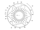
旋回気流発生部50は、筐体10の内部で粉砕部40の上側に配置される。すなわち、旋回気流発生部50の上側には、排出孔116が設けられる。旋回気流発生部50は、回転することで、筐体10の内部に旋回気流を発生させる。そして、旋回気流発生部50は、旋回気流を発生させることで、粉粒体に遠心力を付与する。旋回気流発生部50の詳細について、新たな図面を参照して説明する。図4は、旋回気流発生部及び案内部の平面図である。図1及び図4に示すように、旋回気流発生部50は、第2回転体51と、複数枚のブレード52と、を備える。 <1.5 Configuration of SwirlingAirflow Generating Unit 50>
The swirlingairflow generating unit 50 is disposed above the crushing unit 40 inside the housing 10. That is, the discharge hole 116 is provided on the upper side of the swirling airflow generation unit 50. The swirling airflow generation unit 50 generates a swirling airflow inside the housing 10 by rotating. Then, the swirling airflow generation unit 50 generates a swirling airflow to apply a centrifugal force to the granular material. The details of the swirling airflow generation unit 50 will be described with reference to new drawings. FIG. 4 is a plan view of the swirling air flow generating unit and the guiding unit. As shown in FIG. 1 and FIG. 4, the swirling airflow generation unit 50 includes a second rotating body 51 and a plurality of blades 52.
旋回気流発生部50は、筐体10の内部で粉砕部40の上側に配置される。すなわち、旋回気流発生部50の上側には、排出孔116が設けられる。旋回気流発生部50は、回転することで、筐体10の内部に旋回気流を発生させる。そして、旋回気流発生部50は、旋回気流を発生させることで、粉粒体に遠心力を付与する。旋回気流発生部50の詳細について、新たな図面を参照して説明する。図4は、旋回気流発生部及び案内部の平面図である。図1及び図4に示すように、旋回気流発生部50は、第2回転体51と、複数枚のブレード52と、を備える。 <1.5 Configuration of Swirling
The swirling
<1.5.1 第2回転体51の構成>
図4に示すように、第2回転体51は、平面視円形である。すなわち、第2回転体51は円板状である。第2回転体51には、第2シャフト32が回り止めされつつ、固定される。第2回転体51と第2シャフト32とは、中心が中心軸C1と重なる。なお、第2シャフト32の固定は、不図示の貫通孔に圧入することでなされてもよいし、ねじ止め、溶接、接着等、を採用してもよい。また、キー及びキー溝を用いて、回り止めを行ってもよい。これにより、第2シャフト32が回転することで、第2回転体51、すなわち、旋回気流発生部50は、中心軸C1周りに回転する。 <1.5.1 Configuration ofSecond Rotator 51>
As shown in FIG. 4, the secondrotating body 51 is circular in plan view. That is, the 2nd rotary body 51 is disk shape. The second shaft 32 is fixed to the second rotating body 51 while being prevented from rotating. The centers of the second rotating body 51 and the second shaft 32 overlap with the central axis C1. The second shaft 32 may be fixed by press-fitting into a through hole (not shown), or may be screwed, welded, bonded, or the like. In addition, the locking may be performed using a key and a key groove. As a result, when the second shaft 32 rotates, the second rotating body 51, that is, the swirling air flow generation unit 50 rotates around the central axis C1.
図4に示すように、第2回転体51は、平面視円形である。すなわち、第2回転体51は円板状である。第2回転体51には、第2シャフト32が回り止めされつつ、固定される。第2回転体51と第2シャフト32とは、中心が中心軸C1と重なる。なお、第2シャフト32の固定は、不図示の貫通孔に圧入することでなされてもよいし、ねじ止め、溶接、接着等、を採用してもよい。また、キー及びキー溝を用いて、回り止めを行ってもよい。これにより、第2シャフト32が回転することで、第2回転体51、すなわち、旋回気流発生部50は、中心軸C1周りに回転する。 <1.5.1 Configuration of
As shown in FIG. 4, the second
<1.5.2 ブレード52の構成>
第2回転体51の上面には、放射状に延び、複数枚のブレード52が周方向に等間隔で固定されている。複数枚のブレードは、例えば、第2回転体51の上面に形成された凹溝に挿入した後、溶接、接着等で固定してもよい。第2回転体51の上面に固定されたブレード52は、上側が外側に拡がる。すなわち、旋回気流発生部50が回転したとき、ブレード52の上端部分の外側の端部が通過する部分が、ブレード52の通過領域において、最も外側の部分となる。 <1.5.2 Configuration ofBlade 52>
The plurality ofblades 52 are fixed on the upper surface of the second rotating body 51 at equal intervals in the circumferential direction. The plurality of blades may be fixed by welding, adhesion, or the like after being inserted into, for example, a recessed groove formed on the upper surface of the second rotating body 51. The upper side of the blade 52 fixed to the upper surface of the second rotating body 51 extends outward. That is, when the swirling airflow generation unit 50 rotates, the portion through which the outer end of the upper end portion of the blade 52 passes is the outermost portion in the passage area of the blade 52.
第2回転体51の上面には、放射状に延び、複数枚のブレード52が周方向に等間隔で固定されている。複数枚のブレードは、例えば、第2回転体51の上面に形成された凹溝に挿入した後、溶接、接着等で固定してもよい。第2回転体51の上面に固定されたブレード52は、上側が外側に拡がる。すなわち、旋回気流発生部50が回転したとき、ブレード52の上端部分の外側の端部が通過する部分が、ブレード52の通過領域において、最も外側の部分となる。 <1.5.2 Configuration of
The plurality of
ブレード52は、旋回気流発生部50の旋回方向と直交する面を有する。旋回気流発生部50が回転することで、筐体10の内部には、周方向に流れる気流が発生する。図4に示すように、旋回気流発生部50は、平面視において、反時計回り方向Rdに回転する。旋回気流発生部50の、回転によって筐体10、すなわち、ハウジング筒部112の内部には、ハウジング筒部112に沿って、反時計回り方向Rdの旋回する気流(以下、旋回気流とする)が発生する。また、詳細は後述するが、粉粒体は、旋回気流発生部50で発生する旋回気流によって、その粒子の大きさによって選別(以下、分級とする)される。
The blade 52 has a plane orthogonal to the turning direction of the turning air flow generation unit 50. As the swirling airflow generation unit 50 rotates, an airflow flowing in the circumferential direction is generated inside the housing 10. As shown in FIG. 4, the swirling airflow generation unit 50 rotates in a counterclockwise direction Rd in a plan view. An air flow (hereinafter referred to as a swirling air flow) swirling in the counterclockwise direction Rd along the housing cylindrical portion 112 in the housing 10, that is, the housing cylindrical portion 112 by the rotation of the swirling air flow generation unit 50. Occur. In addition, although the details will be described later, the granular material is sorted (hereinafter classified) according to the size of the particle by the swirling airflow generated by the swirling airflow generation unit 50.
<1.6 案内部60の構成>
図1、図4に示すように、案内部60は、ハウジング筒部112の内部に配置された、案内板61と、支持リブ62とを備える。案内板61は、案内部材の一例である。 <1.6 Configuration ofGuide Unit 60>
As shown in FIGS. 1 and 4, theguide portion 60 includes a guide plate 61 and a support rib 62 which are disposed inside the housing cylindrical portion 112. The guide plate 61 is an example of a guide member.
図1、図4に示すように、案内部60は、ハウジング筒部112の内部に配置された、案内板61と、支持リブ62とを備える。案内板61は、案内部材の一例である。 <1.6 Configuration of
As shown in FIGS. 1 and 4, the
<1.6.1 案内板61の構成>
図4に示すように、ハウジング筒部112の内部に複数枚(ここでは、6枚)の案内板61が、周方向に等間隔に配列されている。案内板61は、長方形板であり、案内板61は、上下に延びる。そして、案内板61は、旋回気流発生部50と径方向に対向する案内面611を備える。図1に示すように、案内面611の下端部は、旋回気流発生部50のブレード52の下端部と、同じ又は略同じ位置まで伸びている。 <1.6.1 Configuration ofGuide Plate 61>
As shown in FIG. 4, a plurality of (here, six)guide plates 61 are arranged at equal intervals in the circumferential direction inside the housing cylindrical portion 112. The guide plate 61 is a rectangular plate, and the guide plate 61 extends vertically. And the guide plate 61 is provided with the guide surface 611 which opposes the turning air flow generation part 50 to radial direction. As shown in FIG. 1, the lower end portion of the guide surface 611 extends to the same or substantially the same position as the lower end portion of the blade 52 of the swirling airflow generation unit 50.
図4に示すように、ハウジング筒部112の内部に複数枚(ここでは、6枚)の案内板61が、周方向に等間隔に配列されている。案内板61は、長方形板であり、案内板61は、上下に延びる。そして、案内板61は、旋回気流発生部50と径方向に対向する案内面611を備える。図1に示すように、案内面611の下端部は、旋回気流発生部50のブレード52の下端部と、同じ又は略同じ位置まで伸びている。 <1.6.1 Configuration of
As shown in FIG. 4, a plurality of (here, six)
図4に示すように、案内板61は、案内面611の旋回気流発生部50、すなわち、第2回転体51の回転方向の前側が後側に比べて内側になるように、ハウジング筒部112の内面に固定されている。なお、案内板61の固定方法としては、溶接、接着等を挙げることができるが、これに限定されず、ハウジング筒部112に設けられた溝に挿入して固定する構成等であってもよい。案内板61を確実に固定できる固定方法を広く採用できる。
As shown in FIG. 4, the guide plate 61 is provided with the housing cylindrical portion 112 such that the front side of the rotational air flow generation portion 50 of the guide surface 611, that is, the second rotary body 51 in the rotational direction is inside compared to the rear side. It is fixed to the inner surface of the In addition, as a fixing method of the guide plate 61, welding, adhesion, etc. can be mentioned, but it is not limited to this, and a configuration in which it is inserted and fixed in a groove provided in the housing cylindrical portion 112 may be used. . A wide variety of fixing methods capable of securely fixing the guide plate 61 can be adopted.
図4に示すように、案内面611の旋回気流発生部50の回転方向の前端部から周方向に沿って延長した面612は、旋回気流発生部50のブレード52が通過する領域よりも外側に位置する。案内面611は、旋回気流発生部50で発生した気流が、旋回気流発生部50に直接吹きつけられないように、内側に案内する。これにより、旋回気流によって旋回する粉粒体が、ブレード52に衝突するのを抑制しつつ、内側に案内する。
As shown in FIG. 4, a surface 612 extending along the circumferential direction from the front end of the rotational flow generating unit 50 of the guide surface 611 in the rotational direction is outside the area through which the blade 52 of the rotational flow generating unit 50 passes. To position. The guide surface 611 guides the airflow generated by the swirling airflow generation unit 50 inward so that the airflow is not directly blown to the swirling airflow generation unit 50. As a result, the granular material swirled by the swirling air current is guided inward while suppressing collision with the blade 52.
<1.6.2 支持リブ62の構成>
図1、図4に示すように、支持リブ62は、案内板61の案内面611と反対側の面とハウジング筒部112との内面とに固定される板状である。支持リブ62は、案内板61を固定している。支持リブ62を備えていることで、案内板61に気流が吹き付けられたときのたわみを抑制し、案内板61が、旋回気流を内側に案内する。 <1.6.2 Configuration ofSupport Rib 62>
As shown in FIGS. 1 and 4, thesupport rib 62 is in the form of a plate fixed to the surface of the guide plate 61 opposite to the guide surface 611 and the inner surface of the housing cylindrical portion 112. The support rib 62 fixes the guide plate 61. By providing the support rib 62, deflection when the air flow is blown to the guide plate 61 is suppressed, and the guide plate 61 guides the swirling air flow inward.
図1、図4に示すように、支持リブ62は、案内板61の案内面611と反対側の面とハウジング筒部112との内面とに固定される板状である。支持リブ62は、案内板61を固定している。支持リブ62を備えていることで、案内板61に気流が吹き付けられたときのたわみを抑制し、案内板61が、旋回気流を内側に案内する。 <1.6.2 Configuration of
As shown in FIGS. 1 and 4, the
本実施形態において、支持リブ62は、案内板61の上下中央に1個設けられている。しかしながら、支持リブ62は、複数個設けられていてもよい。また、案内板61の全体を支持するような、支持リブ62を備えていてもよい。
In the present embodiment, one support rib 62 is provided at the upper and lower center of the guide plate 61. However, a plurality of support ribs 62 may be provided. Moreover, you may provide the support rib 62 which supports the whole guide plate 61. FIG.
<1.6.3 案内部の他の例について>
案内部60の他の例について説明する。図5は、案内板の他の取り付け方を示す断面図である。図5に示すように、案内板61を、ハウジング天板部114の下面に固定するようにしてもよい。図5では、案内板61をハウジング天板部114にねじ止めで固定しているが、ねじ止め以外にも溶接、溶着等を採用してもよい。また、図5に示すように、ハウジング天板部114の下面に直接取り付けて固定する案内板61aであってもよく、ハウジング天板部114の下面に形成され上側に凹む凹部に挿入して固定する案内板61bであってもよい。このように構成することで、ハウジング天板部114を取り外すことで、案内板(61a、61b)を外部に取り出すことができるため、案内板(61a、61b)のメンテナンスが容易である。なお、案内板をハウジング天板部114に取り付ける場合、案内板はハウジング天板部114の開閉時に邪魔になりにくい形状であればよい。また、ハウジング天板部114はヒンジを介することなく、フランジ部113に取り付けてもよい。 <1.6.3 About another example of a guidance part>
Another example of the guidingunit 60 will be described. FIG. 5 is a cross-sectional view showing another way of attaching the guide plate. As shown in FIG. 5, the guide plate 61 may be fixed to the lower surface of the housing top plate portion 114. In FIG. 5, the guide plate 61 is fixed to the housing top plate portion 114 by screwing, but welding, welding or the like may be employed other than screwing. Further, as shown in FIG. 5, the guide plate 61a may be directly attached to and fixed to the lower surface of the housing top plate portion 114, or may be inserted into a concave portion formed on the lower surface of the housing top plate portion 114 and recessed upward. It may be a guide plate 61b. With this configuration, by removing the housing top plate portion 114, the guide plates (61a, 61b) can be taken out to the outside, so maintenance of the guide plates (61a, 61b) is easy. In addition, when attaching a guide plate to the housing top plate part 114, a guide plate should just be a shape which does not become obstructive at the time of opening and closing of the housing top plate part 114. As shown in FIG. In addition, the housing top plate portion 114 may be attached to the flange portion 113 without a hinge.
案内部60の他の例について説明する。図5は、案内板の他の取り付け方を示す断面図である。図5に示すように、案内板61を、ハウジング天板部114の下面に固定するようにしてもよい。図5では、案内板61をハウジング天板部114にねじ止めで固定しているが、ねじ止め以外にも溶接、溶着等を採用してもよい。また、図5に示すように、ハウジング天板部114の下面に直接取り付けて固定する案内板61aであってもよく、ハウジング天板部114の下面に形成され上側に凹む凹部に挿入して固定する案内板61bであってもよい。このように構成することで、ハウジング天板部114を取り外すことで、案内板(61a、61b)を外部に取り出すことができるため、案内板(61a、61b)のメンテナンスが容易である。なお、案内板をハウジング天板部114に取り付ける場合、案内板はハウジング天板部114の開閉時に邪魔になりにくい形状であればよい。また、ハウジング天板部114はヒンジを介することなく、フランジ部113に取り付けてもよい。 <1.6.3 About another example of a guidance part>
Another example of the guiding
図6は、本発明にかかる粉体処理装置に用いられる案内部の他の例を示す平面図である。図6に示すように、湾曲した案内板63であってもよい。このような案内板63では、案内面631も曲面となる。そして、案内面631の第2回転体51の回転方向の前端部から周方向に沿って延長した面632が、旋回気流発生部50のブレード52が通過する領域よりも外側になるように、案内板63が配置されている。このように、曲面状の案内面631を備えることで、旋回気流の案内を円滑に行うことが可能である。なお、案内面631は、外側に凸の曲面であるが、これに限定されず、内側に凸形状の曲面であってもよい。旋回気流の流速、気流の粘度等によって、渦が発生しにくい形状を広く採用できる。
FIG. 6 is a plan view showing another example of the guide portion used in the powder processing apparatus according to the present invention. As shown in FIG. 6, a curved guide plate 63 may be used. In such a guide plate 63, the guide surface 631 is also a curved surface. And, the guide 631 is guided such that the surface 632 extending along the circumferential direction from the front end of the second rotary body 51 in the rotational direction of the guide surface 631 is outside the area through which the blade 52 of the swirling air flow generation unit 50 passes A plate 63 is disposed. Thus, by providing the curved guide surface 631, it is possible to smoothly guide the swirling air flow. In addition, although the guide surface 631 is a curved surface convex to the outer side, it is not limited to this, A curved surface convex shape may be sufficient as inner side. Depending on the flow velocity of the swirling air flow, the viscosity of the air flow, and the like, it is possible to widely adopt a shape in which the vortices are not easily generated.
さらに、図7に示すような、案内部材64、65、66を備えていてもよい。図7は、案内部のさらに他の例を示す平面図である。図7に示すように、案内部材64として、平板状の案内板ではなく、径方向に突出する案内部材64を用いてもよい。このとき、案内部材64の案内面641の第2回転体51の回転方向の前方側の端部を伸ばした面が、旋回気流発生部50のブレード52が通過する領域よりも外側になる。また、案内部材65のように、案内面651を長くしてもよいし、案内部材66のように案内面661を曲面状にしてもよい。案内部材64、65、66は、ハウジング11と一体的に形成してもよい。また、別部材として作製された案内部材64、65、66をハウジング11の内部に固定してもよい。そして、案内面641、651、661の第2回転体51の回転方向の前方側の端部を延長した面642、652、662は、旋回気流発生部50のブレード52が通過する領域よりも外側になる。
Furthermore, guide members 64, 65, 66 as shown in FIG. 7 may be provided. FIG. 7 is a plan view showing still another example of the guide portion. As shown in FIG. 7, as the guide member 64, not a flat guide plate but a guide member 64 protruding in the radial direction may be used. At this time, the surface of the guide surface 641 of the guide member 64 in which the end on the front side in the rotational direction of the second rotating body 51 is extended is outside the area where the blade 52 of the swirling air flow generation unit 50 passes. Further, like the guide member 65, the guide surface 651 may be elongated, or the guide surface 661 may be curved like the guide member 66. The guide members 64, 65, 66 may be integrally formed with the housing 11. Further, the guide members 64, 65, 66 manufactured as separate members may be fixed to the inside of the housing 11. And the surfaces 642, 652, 662 which extended the end by the side of the front of the rotation direction of the 2nd rotary body 51 of the guide surface 641, 651, 661 are the outer sides from the field where the blade 52 of swirling airflow generation part 50 passes. become.
以上説明した、案内面611、631、641、651、661は、上下に延びる面、すなわち、上端部から下端部にかけて周方向に同じ位置にある面で構成されている。しかしながら、これに限定されるものではない。例えば、案内面の上側が下側に対して、第1回転体41の回転方向における前方側に位置していてもよい。これにより、旋回気流を円滑に内側に案内できる。
The guide surfaces 611, 631, 641, 651, and 661 described above are surfaces that extend vertically, that is, surfaces that are at the same position in the circumferential direction from the upper end to the lower end. However, it is not limited to this. For example, the upper side of the guide surface may be located on the front side in the rotation direction of the first rotating body 41 with respect to the lower side. Thereby, the swirling air flow can be guided to the inside smoothly.
<1.7 気流流出部70の構成>
気流流出部70は、気流流入部14から流入した気流(空気)を外部に排出する。図1に示すように、気流流出部70は、ハウジング天板部114の上面に取り付けられる。気流流出部70は、排気筒部71と、排気フランジ72と、を備える。排気筒部71は、円筒形であり、ハウジング天板部114の中央に設けられた排出孔116と連通する。そして、ハウジング11の内部の空気は、排出孔116を介して排気筒部71に流入する。 <1.7 Configuration ofAirflow Outflow Unit 70>
The airflow outflow portion 70 discharges the air flow (air) flowing in from the air flow inflow portion 14 to the outside. As shown in FIG. 1, the air flow outflow portion 70 is attached to the upper surface of the housing top plate portion 114. The air flow outflow portion 70 includes an exhaust cylinder portion 71 and an exhaust flange 72. The exhaust cylinder portion 71 is cylindrical and communicates with the discharge hole 116 provided at the center of the housing top plate portion 114. Then, the air inside the housing 11 flows into the exhaust cylinder portion 71 through the discharge hole 116.
気流流出部70は、気流流入部14から流入した気流(空気)を外部に排出する。図1に示すように、気流流出部70は、ハウジング天板部114の上面に取り付けられる。気流流出部70は、排気筒部71と、排気フランジ72と、を備える。排気筒部71は、円筒形であり、ハウジング天板部114の中央に設けられた排出孔116と連通する。そして、ハウジング11の内部の空気は、排出孔116を介して排気筒部71に流入する。 <1.7 Configuration of
The air
排気フランジ72は、ハウジング天板部114の上面に不図示のガスケットを介して配置されてよい。そして、排気フランジ72は、ハウジング天板部114に、例えば、ねじにて固定される。これにより、ハウジング天板部114と排気筒部71との間の密閉性を高め、気流の漏れを抑制する。ガスケットに替えて、Oリング等を用いてもよい。また、気流流出部70とハウジング天板部114との一方に凹部を他方に凸部を形成し、凹部に凸部を挿入することで、密閉する構成としてもよい。
The exhaust flange 72 may be disposed on the upper surface of the housing top plate 114 via a gasket (not shown). Then, the exhaust flange 72 is fixed to the housing top plate portion 114 by, for example, a screw. Thereby, the sealability between the housing top plate portion 114 and the exhaust cylinder portion 71 is enhanced, and the leakage of the air flow is suppressed. Instead of the gasket, an O-ring or the like may be used. Alternatively, a concave portion may be formed in one of the air flow outlet portion 70 and the housing top plate portion 114, and a convex portion may be formed in the other, and the convex portion may be inserted into the concave portion to seal.
<2. 粉体処理装置の動作について>
本発明にかかる粉体処理装置Aは、以上示した構成を有している。次に、粉体処理装置Aを使用した粉体処理システムについて説明し、粉体処理システムに含まれる粉体処理装置の動作について説明する。図8は、本発明にかかる粉体処理システムの一例の概略配置図である。図8に示す粉体処理システムCLは、原料供給装置Maと、粉体処理装置Aと、フィルタ装置Ftと、ブロワBwとを備える。 <2. About operation of powder processing equipment>
The powder processing apparatus A according to the present invention has the configuration described above. Next, a powder processing system using the powder processing apparatus A will be described, and the operation of the powder processing apparatus included in the powder processing system will be described. FIG. 8 is a schematic layout view of an example of the powder processing system according to the present invention. The powder processing system CL shown in FIG. 8 includes a raw material supply device Ma, a powder processing device A, a filter device Ft, and a blower Bw.
粉体処理装置Aは、架台Caの水平面に不図示のねじ等で固定されている。そして、粉体処理装置Aの気流流出部70とフィルタ装置Ftの流入部Ft3とが配管を介して接続される。フィルタ装置Ftは、例えば、バグフィルタである。フィルタ装置Ftは、ハウジングFt1と、仕切部Ft2と、流入部Ft3と、流出部Ft4と、濾材Ft5と、取り出し口Ft6とを備える。フィルタ装置Ftでは、仕切部Ft2がハウジングFt1の内部を上部と下部に仕切る。そして、仕切部Ft2には、複数個の貫通孔が設けられている。ハウジングFt1の仕切部Ft2よりも下側には、仕切部Ft2の貫通孔の周囲を囲むとともに下側に延びる筒状の濾材Ft5が配置されている。
The powder processing apparatus A is fixed to the horizontal surface of the pedestal Ca with a screw or the like (not shown). Then, the air flow outflow portion 70 of the powder processing apparatus A and the inflow portion Ft3 of the filter device Ft are connected via a pipe. The filter device Ft is, for example, a bug filter. The filter device Ft includes a housing Ft1, a partition Ft2, an inflow portion Ft3, an outflow portion Ft4, a filter medium Ft5, and an outlet Ft6. In the filter device Ft, the partition part Ft2 divides the inside of the housing Ft1 into an upper part and a lower part. The partition Ft2 is provided with a plurality of through holes. On the lower side of the partition Ft2 of the housing Ft1, a cylindrical filter material Ft5 surrounding the periphery of the through hole of the partition Ft2 and extending downward is disposed.
粉体処理装置Aからの気流は、流入部Ft3からハウジングFt1内部に流入し、濾材Ft5を通過し、流出部Ft4から外部に流出する。このとき、濾材Ft5の外面に、粉粒体が捕集される。フィルタ装置Ftでは、図示を省略したパイプから、定期的に、圧縮した気体(圧縮空気)を吹き付けて、濾材Ft5で捕集された粉粒体を下側に落とす。
The air flow from the powder processing apparatus A flows into the housing Ft1 from the inflow portion Ft3, passes through the filter medium Ft5, and flows out from the outflow portion Ft4. At this time, particulate matter is collected on the outer surface of the filter medium Ft5. In the filter device Ft, compressed gas (compressed air) is periodically sprayed from a pipe (not shown) to drop the powder and particulate matter collected by the filter medium Ft5 downward.
ハウジングFt1の下端に取り出し口Ft6が設けられている。取り出し口Ft6からハウジングFt5の下部に溜まった粉粒体が取り出される。なお、粉体処理システムCLでは、取り出し口Ft6から取り出される粉粒体が、分級後の粉粒体、すなわち、製造品である。
An outlet Ft6 is provided at the lower end of the housing Ft1. The powder particles accumulated in the lower part of the housing Ft5 are taken out from the takeout port Ft6. In the powder processing system CL, the powder particles taken out of the takeout port Ft6 are powder particles after classification, that is, manufactured articles.
フィルタ装置Ftの流出部Ft4は、ブロワBwに配管を介して接続される。ブロワBwは、流出部Ft4と接続された配管に負圧を発生させる。この負圧の発生によって、フィルタ装置Ft、粉体処理装置A及びこれらを繋ぐ配管内にブロワBwに向かう気流を発生させる。また、粉体処理装置Aでは、この負圧によって、気流流入部14から気流が流入する。なお、気流流入部14の外側に別途ブロワ(不図示)を設けて、発生した気流を強制的に流入してもよい。
The outlet Ft4 of the filter device Ft is connected to the blower Bw via a pipe. The blower Bw generates a negative pressure in the pipe connected to the outlet Ft4. Due to the generation of the negative pressure, an air flow toward the blower Bw is generated in the filter device Ft, the powder processing device A, and the pipe connecting them. Further, in the powder processing apparatus A, the negative pressure causes the air flow from the air flow inflow portion 14. Note that a separate blower (not shown) may be provided outside the air flow inlet portion 14 to force the generated air flow.
粉体処理装置Aの動作について説明する。粉体処理装置Aでは、第1回転体41及び第2回転体51が回転している状態で、原料供給部20から塊状の原料が供給される。原料供給部20から供給された原料は、粉砕部40の第1回転体41に落下する。原料は、ハンマー42の粉砕刃423とライナー43の粉砕刃432とで粉粒体に粉砕される。
The operation of the powder processing apparatus A will be described. In the powder processing apparatus A, in a state where the first rotating body 41 and the second rotating body 51 are rotating, bulk material is supplied from the material supply unit 20. The raw material supplied from the raw material supply unit 20 falls on the first rotating body 41 of the pulverizing unit 40. The raw material is crushed into powder by a crushing blade 423 of the hammer 42 and a crushing blade 432 of the liner 43.
粉体処理装置Aでは、上述のとおり気流流入部14から空気(気流)が、ハウジング11の内部に流入している。気流流入部14から流入した気流は、第1回転体41とボトムカバー15との隙間から径方向外側に向かって流れ、第1回転体41とライナー43との間から、ハウジング筒部112に沿って上側に流れる。気流の流出先は、気流流出部70である。そのため、第1回転体41とライナー43との間から流出する気流は、上側に向かうとともに、内側に向かう。また、気流は、第1回転体41とライナー43との間を通過するときに、粉砕された粉粒体と一緒に移動する。すなわち、粉砕部40で粉砕された粉粒体は、搬送気流によって、上側及び内側に向かって搬送される。
In the powder processing apparatus A, air (air flow) flows into the inside of the housing 11 from the air flow inflow portion 14 as described above. The air flow introduced from the air flow in-flow portion 14 flows radially outward from the gap between the first rotating body 41 and the bottom cover 15, and along the housing cylindrical portion 112 from between the first rotating body 41 and the liner 43 Flow upwards. The outflow destination of the air flow is the air flow outflow portion 70. Therefore, the air flow flowing out between the first rotating body 41 and the liner 43 is directed upward and inward. In addition, when the air flow passes between the first rotating body 41 and the liner 43, the air flow moves together with the pulverized powder. That is, the granular material crushed by the crushing part 40 is conveyed toward the upper side and the inside by the carrier air flow.
ハウジング11の上部では、旋回気流発生部50によって旋回気流が発生している。気流流入部14から流入した搬送気流は、旋回気流と合流する。このとき、搬送気流に含まれる粉粒体には、搬送気流による内側に向かう力F1と、旋回気流による外側に向かう力F2の2つの力が作用する。力F1は、搬送気流の流量(流速)によって変化し、搬送気流が大きいほど力F1も大きくなる。また、力F2は、旋回気流の流量(流速)、すなわち、旋回気流発生部50の回転数によって変化し、旋回気流発生部50の回転数が高いほど力F2も大きくなる。
In the upper part of the housing 11, a swirling airflow is generated by the swirling airflow generation unit 50. The carrier air flowed in from the air flow in portion 14 merges with the swirling air flow. At this time, two forces of a force F1 directed inward by the carrier air flow and a force F2 directed outward by the swirling air flow act on the powder particles contained in the carrier air flow. The force F1 changes according to the flow rate (flow velocity) of the carrier air flow, and the force F1 also increases as the carrier air flow increases. The force F2 changes according to the flow rate (flow velocity) of the swirling airflow, that is, the rotation speed of the swirling airflow generation unit 50, and the force F2 also increases as the rotation speed of the swirling airflow generation unit 50 increases.
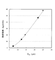
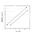
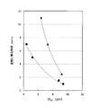
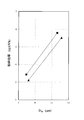
以上のことから、搬送気流によって搬送される粉粒体のうち、気流流出部70から排出される気流と共に搬送される粉粒体の粒径は、搬送気流の流量と、旋回気流発生部50の回転数で決まる。さらに詳しく説明すると、気流流出部70から排出される粉粒体のメジアン径D50は、搬送気流の流量の平方根に比例し、旋回気流発生部50の回転数に反比例する。粉体処理装置Aでは、搬送気流の流量と、旋回気流発生部50の回転数を調整することで、気流流出部70から排出される、すなわち、分級される粉粒体の粒径を決められた粒径に調整できる。なお、メジアン径D50とは、粉粒体を粒径順に並べたとき、その粒径よりも小さい径の粉粒体の数と大きい径の粉粒体の数とが同じになる粒径である。
From the above, among the granular materials carried by the carrier air flow, the particle size of the granular material carried together with the air flow discharged from the air flow outflow portion 70 is the flow rate of the carrier air flow and It depends on the number of revolutions. More specifically, the median diameter D 50 of the particulate matter discharged from the air flow outflow portion 70 is proportional to the square root of the flow rate of the carrier air flow, and inversely proportional to the rotational speed of the swirling air flow generation portion 50. In the powder processing apparatus A, by adjusting the flow rate of the carrier air flow and the rotation speed of the swirling air flow generation unit 50, the particle size of the powder particles discharged from the air flow outflow unit 70 is determined. The particle size can be adjusted to The median diameter D 50 is a particle diameter at which the number of powder particles having a diameter smaller than the particle diameter is equal to the number of powder particles having a larger diameter when the particles are arranged in the order of particle diameter. is there.
また、分級によって気流流出部70から排出されない粉粒体は、決められた粒径よりも大きな粒径を有する。このような粉粒体は、旋回気流によって外側に押し出され、ハウジング筒部112の内面に接触し、その後、ハウジング筒部112の内面に沿って下側に移動する。そして、再度、ハンマー42の粉砕刃423とライナー43の粉砕刃432によって粉砕された後、再度、搬送気流によって、上側に搬送される。
Moreover, the granular material which is not discharged | emitted from the airflow outflow part 70 by classification has a larger particle size than the determined particle size. Such particulate matter is pushed outward by the swirling air flow, contacts the inner surface of the housing cylindrical portion 112, and then moves downward along the inner surface of the housing cylindrical portion 112. Then, after being crushed again by the crushing blade 423 of the hammer 42 and the crushing blade 432 of the liner 43, the material is again conveyed upward by the conveying air flow.
このように、ハンマー42とライナー43とによる粉砕、搬送気流による搬送及び旋回気流による分級を繰り返すことで、原料を決められた粒径及びそれ以下の粒径に粉砕した粉粒体を生成する。なお、生成された粉粒体は、フィルタ装置Ftで捕集されて、取り出される。
As described above, the pulverization by the hammer 42 and the liner 43, the conveyance by the conveyance air flow, and the classification by the swirling air flow are repeated to generate the powder particles which are crushed into the particle diameter of the determined particle diameter and the particle diameter smaller than that. In addition, the produced granular material is collected by the filter device Ft and taken out.
本発明にかかる粉体処理装置Aでは、ハウジング11の内部に、案内板61を配置している。案内板61の案内面611は、旋回気流を内側に案内する。この動作によって、旋回気流が内側に向かう。旋回気流による力F1は、案内板61が配置されていない場合よりも小さくできる。そのため、所定の粒径を得るための、搬送気流の流量及び旋回気流発生部50の回転数を低くすることが可能である。このことを換言すると、搬送気流の流量を少なく抑えることができるため、粉粒体の微細化が可能となる。また、搬送気流の流量及び旋回気流発生部50の回転数を低くすることで消費電力を減らす、すなわち、省エネルギ化が可能である。
In the powder processing apparatus A according to the present invention, the guide plate 61 is disposed inside the housing 11. The guide surface 611 of the guide plate 61 guides the swirling air flow inward. By this operation, the swirling air flow is directed inward. The force F1 due to the swirling air flow can be smaller than in the case where the guide plate 61 is not disposed. Therefore, it is possible to lower the flow rate of the carrier air flow and the rotation speed of the swirling air flow generation unit 50 in order to obtain a predetermined particle diameter. In other words, since the flow rate of the carrier air flow can be suppressed to a low level, the fine particles can be miniaturized. In addition, by lowering the flow rate of the carrier air flow and the rotational speed of the swirling air flow generation unit 50, power consumption can be reduced, that is, energy saving can be achieved.
また、案内面611は、旋回気流を円滑に内側に導くように配置されている。そのため、旋回気流を板状の部材に衝突させる従来の構成に比べて、案内板61に粉粒体が付着しにくく、また、旋回気流で渦が発生しにくい。そのため、粉粒体を円滑かつ効率よく製造できる。
Further, the guide surface 611 is arranged to guide the swirling air flow inward smoothly. Therefore, compared with the conventional configuration in which the swirling airflow collides with the plate-like member, the powder particles are less likely to adhere to the guide plate 61, and vortices are less likely to occur in the swirling airflow. Therefore, powder and granular material can be manufactured smoothly and efficiently.
なお、気流流入部14から、高温で湿度が低い、すなわち、高温乾燥空気を流入させることで、ハンマー42及びライナー43で粉砕した粉粒体の水分を取り除く、いわゆる、気流乾燥装置とすることも可能である。
In addition, it is also possible to use a so-called air flow drying apparatus that removes moisture of the powder particles crushed by the hammer 42 and the liner 43 by flowing high temperature and low humidity from the air flow inflow portion 14, that is, high temperature dry air. It is possible.
<2.1 粉体処理装置の他の例について>
粉体処理装置では、旋回気流発生部50によって発生する旋回気流と搬送気流で搬送された気流を用いて、内側に移動する粉粒体の粒径を調整可能である。このことを利用して、一定未満の粒径の粉粒体を排出しつつ、ハンマー42の粉砕刃423とライナー43の粉砕刃432との間で研磨を繰り返すことで、一定の粒径で、尖った部分が少ない、すなわち、球形に近い粉粒体を生成する(球形化と称する)ことができる。そして、粉体処理装置Aのハウジング筒部112に不図示の取出し口を設けておき、取出し口から取り出すことで、球形化された粉粒体を得ることができる。 <2.1 Another Example of Powder Processing Device>
In the powder processing apparatus, it is possible to adjust the particle size of the powder particles moving inward by using the swirling airflow generated by the swirlingairflow generation unit 50 and the airflow transported by the transport airflow. By using this to repeat grinding between the grinding blade 423 of the hammer 42 and the grinding blade 432 of the liner 43 while discharging powder particles having a particle size of less than a constant particle size, with a constant particle size, It is possible to produce a powder having a small number of pointed parts, ie, close to spherical (referred to as "spheronization"). And the extraction port not shown is provided in the housing cylinder part 112 of the powder processing apparatus A, and it can obtain the spherical powder body by taking out from an extraction port.
粉体処理装置では、旋回気流発生部50によって発生する旋回気流と搬送気流で搬送された気流を用いて、内側に移動する粉粒体の粒径を調整可能である。このことを利用して、一定未満の粒径の粉粒体を排出しつつ、ハンマー42の粉砕刃423とライナー43の粉砕刃432との間で研磨を繰り返すことで、一定の粒径で、尖った部分が少ない、すなわち、球形に近い粉粒体を生成する(球形化と称する)ことができる。そして、粉体処理装置Aのハウジング筒部112に不図示の取出し口を設けておき、取出し口から取り出すことで、球形化された粉粒体を得ることができる。 <2.1 Another Example of Powder Processing Device>
In the powder processing apparatus, it is possible to adjust the particle size of the powder particles moving inward by using the swirling airflow generated by the swirling
このように、粉体処理装置Aでは、案内面611で旋回気流を内側に向けているため、搬送気流の流量が低くても、粉粒体を内側に搬送可能である。搬送気流の流量が低くても、粉粒体がハウジング11の内部に残りにくい。これにより、ハンマー42の粉砕刃423とライナー43の粉砕刃432とで粉砕が繰り返されて、過剰に粉砕される、過粉砕を抑制でき、微粉の発生量を抑制できる。
As described above, in the powder processing apparatus A, since the swirling air flow is directed inward at the guide surface 611, the powder particles can be conveyed inward even if the flow rate of the conveying air flow is low. Even if the flow rate of the carrier air flow is low, the powder particles are unlikely to remain inside the housing 11. Thereby, crushing is repeated by the crushing blade 423 of the hammer 42 and the crushing blade 432 of the liner 43, and excessive crushing which is excessively crushed can be suppressed, and the generation amount of fine powder can be suppressed.
<3. 粉体処理装置の評価について>
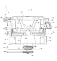
本発明にかかる粉体処理装置Aの特性の評価を行った。比較例として、従来の粉体処理装置Pを用いた。図9は、比較例の試験に用いた従来の粉体処理装置の断面図である。 <3. About evaluation of powder processing equipment>
The characteristics of the powder processing apparatus A according to the present invention were evaluated. The conventional powder processing apparatus P was used as a comparative example. FIG. 9 is a cross-sectional view of a conventional powder processing apparatus used in the test of the comparative example.
図9に示す粉体処理装置Pは、案内板61に替えて内筒81及び垂直ベーン82を備えている以外は、図1に示す粉体処理装置Aと実質上同じ構成を有している。そのため、粉体処理装置Pにおいて、実質上粉体処理装置Aと同じ部分には、同じ符号を付すとともに、同じ部分の詳細な説明は省略する。なお、図9において、本発明の特徴と直接関係しない部分の符号についても省略している。
The powder processing apparatus P shown in FIG. 9 has substantially the same configuration as the powder processing apparatus A shown in FIG. 1 except that an inner cylinder 81 and vertical vanes 82 are provided instead of the guide plate 61. . Therefore, in the powder processing apparatus P, parts substantially the same as the powder processing apparatus A are given the same reference numerals, and detailed descriptions of the same parts will be omitted. In FIG. 9, the reference numerals of parts not directly related to the features of the present invention are also omitted.
図9に示すように、粉体処理装置Pは、ハウジング筒部112の内部に、内筒81を備えている。内筒81は、旋回気流発生部50の外側を包む筒状である。そして、垂直ベーン82は、平板であり、内筒81の外面とハウジング筒部112の内面とをつなぐ。垂直ベーン82は、複数個(例えば、6個)備えられており、径方向に沿って配置される。
As shown in FIG. 9, the powder processing apparatus P includes an inner cylinder 81 inside the housing cylindrical portion 112. The inner cylinder 81 has a cylindrical shape that wraps the outer side of the swirling air flow generation unit 50. The vertical vanes 82 are flat and connect the outer surface of the inner cylinder 81 and the inner surface of the housing cylindrical portion 112. A plurality of (for example, six) vertical vanes 82 are provided and arranged along the radial direction.
粉体処理装置Pでは、旋回気流に搬送された粉粒体は、ハウジング筒部112に沿って周方向に流れ、垂直ベーン82に衝突する。そして、下側に落下する。そして、落下した粉粒体は、再度、粉砕部40で粉砕される。比較例の粉体処理装置Pは、このような構成を有している。
In the powder processing apparatus P, the granular material transported to the swirling air flow in the circumferential direction along the housing cylindrical portion 112 and collides with the vertical vanes 82. And it falls to the lower side. Then, the dropped powdery particles are crushed again by the crushing unit 40. The powder processing apparatus P of the comparative example has such a configuration.
粉体処理装置Pの動作について説明する。粉体処理装置Pでは、粉体処理装置Aと同様、原料供給部20から供給された原料が、粉砕部40の第1回転体41に落下する。原料は、ハンマー42の粉砕刃423とライナー43の粉砕刃432とで粉粒体に粉砕される。そして、粉砕された原料は、搬送気流によって搬送され、ハウジング筒部112の内周と内筒81の外周との間を通過する。その後、旋回気流発生部50で粉粒体を分級する。そして、決められた粒径よりも小さい粉粒体は、ブレード52の隙間を通過して、排出孔116より外部に排出される。また、決められた粒径よりも大きい粉粒体は、内筒81の内側を下方に移動して第1回転体41に落下する。そして、落下した粉粒体は、ハンマー42の粉砕刃423とライナー43の粉砕刃432とで再度、さらに細かい、すなわち、粒径が小さい、粉粒体に粉砕される。粉体処理装置Pでは、以上の動作を繰り返すことで、原料を粉粒体に破砕するとともに、分級を行っている。
The operation of the powder processing apparatus P will be described. In the powder processing apparatus P, as in the powder processing apparatus A, the raw material supplied from the raw material supply unit 20 falls onto the first rotating body 41 of the pulverizing unit 40. The raw material is crushed into powder by a crushing blade 423 of the hammer 42 and a crushing blade 432 of the liner 43. Then, the crushed raw material is conveyed by the conveying air flow, and passes between the inner periphery of the housing cylindrical portion 112 and the outer periphery of the inner cylinder 81. Thereafter, the granular material is classified by the swirling air flow generation unit 50. Then, powder particles smaller than the determined particle diameter pass through the gap of the blade 52 and are discharged to the outside from the discharge hole 116. Further, the powder particles having a particle diameter larger than the determined particle diameter move downward inside the inner cylinder 81 and drop into the first rotating body 41. Then, the dropped powder particles are crushed again into fine particles, that is, particles with a small particle diameter, by the crushing blade 423 of the hammer 42 and the crushing blade 432 of the liner 43. In the powder processing apparatus P, by repeating the above operation, the raw material is crushed into powder particles and classification is performed.
<3.1 試験条件>
以下の評価において、本発明の粉体処理装置Aを用いた試験結果を実施例とし、従来の粉体処理装置Pを用いて行った試験結果を比較例とする。粉砕部40のハンマー42の外側の外径をハンマー外径とする。実施例及び比較例ともに、同じ条件で試験を行っている。試験の条件は以下のとおりである。なお、評価毎に条件が変わっている部分については、評価毎に説明を行う。以下の説明に用いるグラフにおいて、実施例を四角、比較例を三角で示す。
ハンマー粉砕刃の形状 : タテミゾ
ハンマー外径 : 318.1mm
ハンマー個数 : 12個
粉砕部回転数 : 7000rpm
旋回気流発生部回転数 : 2000rpm~7000rpm
粉砕原料 : 重質炭酸カルシウム(粒径約1mm) <3.1 Test conditions>
In the following evaluation, a test result using the powder processing apparatus A of the present invention is taken as an example, and a test result performed using a conventional powder processing apparatus P is taken as a comparative example. Let the outer diameter of the outer side of thehammer 42 of the crushing part 40 be a hammer outer diameter. The tests are conducted under the same conditions in both the example and the comparative example. The conditions of the test are as follows. In addition, about the part to which the condition has changed for every evaluation, it demonstrates for every evaluation. In the graph used for the following description, an Example is shown with a square and a comparative example is shown with a triangle.
Shape of hammer crusher blade: Tatemizo Hammer outer diameter: 318.1 mm
Number of hammers: 12 pcs rotation speed: 7000 rpm
Rotating air flow generator rotation speed: 2000rpm-7000rpm
Pulverized material: Heavy calcium carbonate (particle size about 1 mm)
以下の評価において、本発明の粉体処理装置Aを用いた試験結果を実施例とし、従来の粉体処理装置Pを用いて行った試験結果を比較例とする。粉砕部40のハンマー42の外側の外径をハンマー外径とする。実施例及び比較例ともに、同じ条件で試験を行っている。試験の条件は以下のとおりである。なお、評価毎に条件が変わっている部分については、評価毎に説明を行う。以下の説明に用いるグラフにおいて、実施例を四角、比較例を三角で示す。
ハンマー粉砕刃の形状 : タテミゾ
ハンマー外径 : 318.1mm
ハンマー個数 : 12個
粉砕部回転数 : 7000rpm
旋回気流発生部回転数 : 2000rpm~7000rpm
粉砕原料 : 重質炭酸カルシウム(粒径約1mm) <3.1 Test conditions>
In the following evaluation, a test result using the powder processing apparatus A of the present invention is taken as an example, and a test result performed using a conventional powder processing apparatus P is taken as a comparative example. Let the outer diameter of the outer side of the
Shape of hammer crusher blade: Tatemizo Hammer outer diameter: 318.1 mm
Number of hammers: 12 pcs rotation speed: 7000 rpm
Rotating air flow generator rotation speed: 2000rpm-7000rpm
Pulverized material: Heavy calcium carbonate (particle size about 1 mm)
<3.2 評価1>
評価1では、粉体処理装置A及び粉体処理装置Pの動作条件を以上のとおりとし、各粉体処理装置で搬送気流の流量を変えて試験1、試験2を行った。各試験における搬送気流の流量は、次の通りである。
試験1
搬送気流流量 : 標準流量
試験2
搬送気流流量 : 標準流量の1/3の流量 <3.2Evaluation 1>
In theevaluation 1, the operation conditions of the powder processing apparatus A and the powder processing apparatus P were as described above, and the flow rate of the carrier air flow was changed in each powder processing apparatus, and tests 1 and 2 were performed. The flow rate of the carrier air flow in each test is as follows.
Examination 1
Carrier airflow:Standard flow Test 2
Carrier air flow rate: 1/3 the standard flow rate
評価1では、粉体処理装置A及び粉体処理装置Pの動作条件を以上のとおりとし、各粉体処理装置で搬送気流の流量を変えて試験1、試験2を行った。各試験における搬送気流の流量は、次の通りである。
試験1
搬送気流流量 : 標準流量
試験2
搬送気流流量 : 標準流量の1/3の流量 <3.2
In the
Carrier airflow:
Carrier air flow rate: 1/3 the standard flow rate
なお、標準流量とは、粉体処理装置Pを用いて行われている従来の粉体処理において、粉体処理装置Pに供給される気流、すなわち、搬送気流の流量である。試験1及び試験2の結果を図10、図11に示す。図10は、試験1の結果を示すグラフである。図11は、試験2の結果を示すグラフである。図10、図11に示すグラフは、縦軸が粉砕効率(kg/kW・h)、横軸がメジアン径(D50μm)である。粉砕効率は、単位電力当たりの原料の処理能力を示す。
The standard flow rate is an air flow supplied to the powder processing apparatus P in the conventional powder processing performed using the powder processing apparatus P, that is, the flow rate of the carrier air flow. The results of Tests 1 and 2 are shown in FIG. 10 and FIG. FIG. 10 is a graph showing the results of Test 1. FIG. 11 is a graph showing the results of Test 2. In the graphs shown in FIG. 10 and FIG. 11, the ordinate represents the grinding efficiency (kg / kW · h), and the abscissa represents the median diameter (D 50 μm). The grinding efficiency indicates the throughput of the raw material per unit power.
図10に示すように、搬送気流の流量が多い(標準流量)場合、実施例と比較例とで粉砕効率にほとんど差は現れない。一方、図11に示すように、搬送気流の流量が少ない(標準流量の1/3)場合、実施例の粉砕効率は、比較例の粉砕効率に比べて高くなっている。すなわち、搬送気流の流量が少ない場合において、本発明の粉体処理装置Aは、従来の粉体処理装置Pに比べて、粉砕効率が高いことが分かった。
As shown in FIG. 10, when the flow rate of the carrier air flow is high (standard flow rate), almost no difference appears in the grinding efficiency between the example and the comparative example. On the other hand, as shown in FIG. 11, when the flow rate of the carrier air flow is small (1/3 of the standard flow rate), the crushing efficiency of the example is higher than that of the comparative example. That is, it was found that the powder processing apparatus A of the present invention had a high crushing efficiency compared to the conventional powder processing apparatus P when the flow rate of the carrier air flow was small.
<3.3 評価2>
次に、実施例及び比較例ともに搬送気流の流量を標準流量の1/3.75として、原料の供給を停止した後に無負荷状態になる、すなわち、空転に戻るまでの時間を比較した。その結果を、図12に示す。図12は、原料供給停止後に粉砕部が空転状態に戻るまでの時間を示すグラフである。 <3.3Evaluation 2>
Next, the flow rate of the carrier air flow was set to 1 / 3.75 of the standard flow rate in both the example and the comparative example, and after stopping the supply of the raw material, the time to return to no load, that is, the time to return to idling was compared. The results are shown in FIG. FIG. 12 is a graph showing the time until the grinding unit returns to the idle state after the supply of the raw material is stopped.
次に、実施例及び比較例ともに搬送気流の流量を標準流量の1/3.75として、原料の供給を停止した後に無負荷状態になる、すなわち、空転に戻るまでの時間を比較した。その結果を、図12に示す。図12は、原料供給停止後に粉砕部が空転状態に戻るまでの時間を示すグラフである。 <3.3
Next, the flow rate of the carrier air flow was set to 1 / 3.75 of the standard flow rate in both the example and the comparative example, and after stopping the supply of the raw material, the time to return to no load, that is, the time to return to idling was compared. The results are shown in FIG. FIG. 12 is a graph showing the time until the grinding unit returns to the idle state after the supply of the raw material is stopped.
図12のグラフは、縦軸が原料供給停止した後に粉砕部40の負荷が最小、すなわち、空転状態に戻るまでの時間である。また、横軸は、生成粉粒体のメジアン径D50である。粉粒体がハウジング11の内部で滞留している時間は、処理に要する時間である。
In the graph of FIG. 12, the vertical axis represents the time until the load on the grinding unit 40 is minimized after the supply of the raw material is stopped, that is, the idle state is restored. The horizontal axis is the median diameter D 50 of the product powder granules. The time for which the particulates stay inside the housing 11 is the time required for the treatment.
図12に示すように、原料供給を停止後、空転状態に戻るまでの時間は、メジアン径D50が同じ場合、実施例が比較例に比べて短い。つまり、搬送気流の流量が少ない場合、粉体処理装置Aは、粉体処理装置Pよりも原料を粉砕して、決められた粒径の粉粒体を得るまでの処理時間が短いことがわかった。これにより、搬送気流の流量が少ない場合において、本発明の粉体処理装置Aは、従来の粉体処理装置Pに比べて、処理のタクトタイムを短くすることが可能であることがわかる。
As shown in FIG. 12, after stopping the supply of the raw material, the time to return to the idle state is shorter in the example than in the comparative example when the median diameter D 50 is the same. That is, when the flow rate of the carrier air flow is small, it can be seen that the processing time until the powder processing apparatus A grinds the raw material than the powder processing apparatus P and obtains the powder of the determined particle size is short. The Thereby, it is understood that the powder processing apparatus A of the present invention can shorten the tact time of the processing compared to the conventional powder processing apparatus P when the flow rate of the carrier air flow is small.
<3.4 評価3>
次に、原料を重質炭酸カルシウムから鱗状黒鉛(メジアン径D50が85μm)に変更した。さらに、ライナー43の粉砕刃432として、溝が直交して凸部が矩形状になる角ミゾのライナーを用いている。粉砕部40の回転数は、実施例、比較例ともに6800rpm、旋回気流発生部50の回転数は、実施例、比較例ともに3000rpmと7000rpmとしている。搬送気流の流量は、実施例、比較例ともに標準流量の1/3としている。試験結果を図13に示す。図13は、粉砕効率を示すグラフである。図13のグラフは、図13のグラフと同様、縦軸を粉砕効率、横軸をメジアン径D50としている。 <3.4Evaluation 3>
Next, the raw material was changed from ground calcium carbonate to scaly graphite (median diameter D 50 is 85 μm). Furthermore, as the crushingblade 432 of the liner 43, a square-milling liner in which grooves are orthogonal to each other and a convex portion is rectangular is used. The rotation speed of the crushing unit 40 is 6800 rpm in both the embodiment and the comparative example, and the rotation velocity of the swirling air flow generation unit 50 is 3000 rpm and 7000 rpm in the embodiment and the comparison example. The flow rate of the carrier air flow is 1/3 of the standard flow rate in both the embodiment and the comparative example. The test results are shown in FIG. FIG. 13 is a graph showing the grinding efficiency. Graph of FIG. 13, similar to the graph of FIG. 13, crushing a longitudinal axis efficiency, and the median diameter D 50 of the horizontal axis.
次に、原料を重質炭酸カルシウムから鱗状黒鉛(メジアン径D50が85μm)に変更した。さらに、ライナー43の粉砕刃432として、溝が直交して凸部が矩形状になる角ミゾのライナーを用いている。粉砕部40の回転数は、実施例、比較例ともに6800rpm、旋回気流発生部50の回転数は、実施例、比較例ともに3000rpmと7000rpmとしている。搬送気流の流量は、実施例、比較例ともに標準流量の1/3としている。試験結果を図13に示す。図13は、粉砕効率を示すグラフである。図13のグラフは、図13のグラフと同様、縦軸を粉砕効率、横軸をメジアン径D50としている。 <3.4
Next, the raw material was changed from ground calcium carbonate to scaly graphite (median diameter D 50 is 85 μm). Furthermore, as the crushing
原料を、重質炭酸カルシウムから鱗状黒鉛に変更しても、搬送気流の流量が少ない場合において、本発明にかかる粉体処理装置Aの粉砕効率は、従来の粉体処理装置Pの粉砕効率よりも高いことがわかった。
Even when the raw material is changed from heavy calcium carbonate to squamous graphite, the grinding efficiency of the powder processing apparatus A according to the present invention is smaller than that of the conventional powder processing apparatus P when the flow rate of the carrier air flow is small. It also turned out to be expensive.
<3.5 評価4>
評価4では、原料をポリスチレンとして、試験を行った。ポリスチレンのように割れにくい材料を用いた場合、搬送気流の流量が低いと、従来の粉体処理装置Pでは、粉砕負荷の変動が大きくなり、安定した運転ができなかった。このことから、本発明にかかる粉体処理装置Aは、従来の粉体処理装置Pに比べて低風量における運転の安定性が高いことが分かった。つまり、本発明にかかる粉体処理装置Aは、従来の粉体処理装置Pよりも、低風量化が可能であることが分かった。 <3.5Evaluation 4>
InEvaluation 4, the test was performed using polystyrene as a raw material. When a material such as polystyrene which is hard to break is used and the flow rate of the carrier air flow is low, in the conventional powder processing apparatus P, the fluctuation of the grinding load becomes large and stable operation can not be performed. From this, it was found that the powder processing apparatus A according to the present invention had high operation stability at a low air volume as compared to the conventional powder processing apparatus P. That is, it was found that the powder processing apparatus A according to the present invention can reduce the air flow more than the conventional powder processing apparatus P.
評価4では、原料をポリスチレンとして、試験を行った。ポリスチレンのように割れにくい材料を用いた場合、搬送気流の流量が低いと、従来の粉体処理装置Pでは、粉砕負荷の変動が大きくなり、安定した運転ができなかった。このことから、本発明にかかる粉体処理装置Aは、従来の粉体処理装置Pに比べて低風量における運転の安定性が高いことが分かった。つまり、本発明にかかる粉体処理装置Aは、従来の粉体処理装置Pよりも、低風量化が可能であることが分かった。 <3.5
In
<3.6 評価5>
次に、評価5では、原料をフレーク状粉体塗料(□5mm、厚さ1mm)として、試験を行った。そして、気流流出部70から排出された粉粒体に含まれる微粉(粒径9.25μm未満)の含有率(微粉率)を体積比率で取得した。試験の条件は、評価1の試験2と同じである。その結果を、図14に示す。図14は、生成された粉粒体に含まれる微粉の含有率を示すグラフである。図14は、縦軸を微粉率、横軸をメジアン径D50としている。 <3.6Evaluation 5>
Next, in theevaluation 5, the test was performed with the raw material as a flake-like powder coating (5 mm in diameter, 1 mm in thickness). And the content rate (fine powder rate) of the fine powder (particle size less than 9.25 micrometers) contained in the granular material discharged | emitted from the airflow outflow part 70 was acquired by the volume ratio. The conditions of the test are the same as in the test 2 of Evaluation 1. The results are shown in FIG. FIG. 14 is a graph showing the content of fine powder contained in the produced granular material. 14, the vertical axis fines ratio, and the median diameter D 50 of the horizontal axis.
次に、評価5では、原料をフレーク状粉体塗料(□5mm、厚さ1mm)として、試験を行った。そして、気流流出部70から排出された粉粒体に含まれる微粉(粒径9.25μm未満)の含有率(微粉率)を体積比率で取得した。試験の条件は、評価1の試験2と同じである。その結果を、図14に示す。図14は、生成された粉粒体に含まれる微粉の含有率を示すグラフである。図14は、縦軸を微粉率、横軸をメジアン径D50としている。 <3.6
Next, in the
メジアン径D50が同じ粉粒体を生成する場合、本発明の粉体処理装置Aを用いた方が、従来の粉体処理装置Pを用いる場合に比べて、微粉率が低い。つまり、同量の原料を用いて決められた粒径の粉粒体を生成する場合、本発明の粉体処理装置Aは従来の粉体処理装置Pよりも多くの粉粒体を生成できる。すなわち、本発明の粉体処理装置Aは従来の粉体処理装置Pよりも無駄が少なく、粉体処理の効率が高いことがわかる。
When powder particles having the same median diameter D 50 are produced, the powder processing apparatus A of the present invention has a lower fine powder ratio than that of the conventional powder processing apparatus P. That is, when powder particles having a determined particle diameter are generated using the same amount of raw material, the powder processing apparatus A of the present invention can generate more particles than the conventional powder processing apparatus P. That is, it can be seen that the powder processing apparatus A of the present invention has less waste than the conventional powder processing apparatus P, and the powder processing efficiency is high.
<3.7 評価6>
評価6では、評価1~評価5で用いたものとは大きさが異なる粉体処理装置A1及び粉体処理装置P1を用いて試験を行った。試験条件は以下の通りである。
ハンマー粉砕刃の形状 : タテミゾ
ハンマー外径 : 430.3mm
ハンマー個数 : 32個
粉砕部回転数 : 6600rpm
旋回気流発生部回転数 : 3000rpm~5400rpm
粉砕原料 : 重質炭酸カルシウム(粒径約1mm)
ライナー粉砕刃の形状 : 三角ミゾ
搬送気流の流量 : 標準流量の2/3 <3.7Evaluation 6>
In theevaluation 6, tests were performed using a powder processing apparatus A1 and a powder processing apparatus P1 having different sizes from those used in the evaluation 1 to the evaluation 5. The test conditions are as follows.
Shape of hammer grinding blade: Tatemizo Hammer outer diameter: 430.3 mm
Number of hammers: 32 pcs rotation speed: 6600 rpm
Rotating air flow generator rotation speed: 3000rpm to 5400rpm
Pulverized material: Heavy calcium carbonate (particle size about 1 mm)
Liner crusher blade shape: Triangular slot flow of carrier air flow: 2/3 of standard flow
評価6では、評価1~評価5で用いたものとは大きさが異なる粉体処理装置A1及び粉体処理装置P1を用いて試験を行った。試験条件は以下の通りである。
ハンマー粉砕刃の形状 : タテミゾ
ハンマー外径 : 430.3mm
ハンマー個数 : 32個
粉砕部回転数 : 6600rpm
旋回気流発生部回転数 : 3000rpm~5400rpm
粉砕原料 : 重質炭酸カルシウム(粒径約1mm)
ライナー粉砕刃の形状 : 三角ミゾ
搬送気流の流量 : 標準流量の2/3 <3.7
In the
Shape of hammer grinding blade: Tatemizo Hammer outer diameter: 430.3 mm
Number of hammers: 32 pcs rotation speed: 6600 rpm
Rotating air flow generator rotation speed: 3000rpm to 5400rpm
Pulverized material: Heavy calcium carbonate (particle size about 1 mm)
Liner crusher blade shape: Triangular slot flow of carrier air flow: 2/3 of standard flow
以上の条件で、本発明にかかる粉体処理装置A1と従来の粉体処理装置P1とを用いて、試験を行い、粉砕効率を取得した。試験結果を図15に示す。図15は、粉砕効率を示すグラフである。図15は、縦軸を粉砕効率、横軸をメジアン径D50としている。
Under the above conditions, tests were performed using the powder processing apparatus A1 according to the present invention and the conventional powder processing apparatus P1, and the crushing efficiency was obtained. The test results are shown in FIG. FIG. 15 is a graph showing the grinding efficiency. Figure 15 is crushed ordinate efficiency, and the median diameter D 50 of the horizontal axis.
図15に示すように、本発明にかかる粉体処理装置A1を用いた場合、従来の粉体処理装置P1を用いた場合に比べて、粉砕効率が高くなる。これにより、粉体処理装置の大きさ、ハウジング、粉砕部の大きさ、ハンマーの数が変化しても、案内面を有する本発明にかかる粉体処理装置の方が、従来の粉体処理装置よりも粉砕効率が高いことがわかる。
As shown in FIG. 15, when the powder processing apparatus A1 according to the present invention is used, the pulverization efficiency is higher than when the conventional powder processing apparatus P1 is used. As a result, even if the size of the powder processing apparatus, the size of the housing, the size of the crushing portion, and the number of hammers change, the powder processing apparatus according to the present invention having the guide surface is the conventional powder processing apparatus. It can be seen that the grinding efficiency is higher than that.
以上示したように、本発明にかかる粉体処理装置では、ハウジング内に、ハウジング内部で発生する旋回気流を内側に案内する案内面を有することで、従来の粉体処理装置に比べて、粉砕効率が高く粉体処理時間を短くできる。また、決められた粒径の粉粒体を得るために必要な原料も本発明にかかる粉体処理装置を用いた方が、従来の粉体処理装置を用いる場合よりも少なくて済む。また、本発明の粉体処理装置Aでは、従来の粉体処理装置Pに比べて、流入させる気流流量を少なくできる、すなわち、気流の低流量化が可能である。またこのことから、本発明の粉体処理装置Aでは、従来の粉体処理装置Pに比べて、生成される粉粒体の微細化も可能である。
As described above, in the powder processing apparatus according to the present invention, the housing has a guide surface for guiding the swirling air flow generated inside the housing to the inside, so that crushing is performed compared to the conventional powder processing apparatus. The efficiency is high and the powder processing time can be shortened. In addition, the use of the powder processing apparatus according to the present invention requires less raw materials necessary to obtain powder particles having a determined particle size, as compared to the case of using a conventional powder processing apparatus. In addition, in the powder processing apparatus A of the present invention, compared with the conventional powder processing apparatus P, the flow rate of the air flowed in can be reduced, that is, the flow rate of the air flow can be reduced. In addition, from this point, in the powder processing apparatus A of the present invention, it is possible to make the produced powder particles finer as compared with the conventional powder processing apparatus P.
以上、本発明の実施形態について説明したが、本発明はこの内容に限定されるものではない。また本発明の実施形態は、発明の趣旨を逸脱しない限り、種々の改変を加えることが可能である。
As mentioned above, although embodiment of this invention was described, this invention is not limited to this content. Moreover, the embodiment of the present invention can add various modifications without departing from the spirit of the invention.
10 筐体
11 ハウジング
111 ハウジング底部
112 ハウジング筒部
113 フランジ部
114 ハウジング天板部
115 貫通孔
116 排出孔
12 軸保持部
13 原料受入孔
14 気流流入部
15 ボトムカバー
20 原料供給部
30 駆動部
31 第1シャフト
311 第1プーリ
32 第2シャフト
321 第2プーリ
331 第1ベルト
332 第2ベルト
40 粉砕部
41 第1回転体
412 ハンマー取付部
42 ハンマー
423 粉砕刃
43 ライナー
432 粉砕刃
50 旋回気流発生部
51 第2回転体
52 ブレード
60 案内部
61 案内板
62 支持リブ
63 案内板
64 案内部材
65 案内部材
66 案内部材
70 気流流出部
71 排気筒部
72 排気フランジ
A 粉体処理装置
CL 粉体処理システム
Ft フィルタ装置
Bw ブロワReference Signs List 10 housing 11 housing 111 housing bottom portion 112 housing cylindrical portion 113 flange portion 114 housing top plate portion 115 through hole 116 discharge hole 12 shaft holding portion 13 raw material receiving hole 14 air flow inflow portion 15 bottom cover 20 raw material supply portion 30 drive portion 31 1 shaft 311 first pulley 32 second shaft 321 second pulley 331 first belt 332 second belt 40 crushing unit 41 first rotary body 412 hammer attachment unit 42 hammer 423 crushing blade 43 liner 432 crushing blade 50 swirling air flow generation unit 51 Second rotating body 52 blade 60 guide portion 61 guide plate 62 support rib 63 guide plate 64 guide member 65 guide member 66 guide member 70 air flow outflow portion 71 exhaust tube portion 72 exhaust flange A powder processing device CL Body treatment system Ft filter device Bw blower
11 ハウジング
111 ハウジング底部
112 ハウジング筒部
113 フランジ部
114 ハウジング天板部
115 貫通孔
116 排出孔
12 軸保持部
13 原料受入孔
14 気流流入部
15 ボトムカバー
20 原料供給部
30 駆動部
31 第1シャフト
311 第1プーリ
32 第2シャフト
321 第2プーリ
331 第1ベルト
332 第2ベルト
40 粉砕部
41 第1回転体
412 ハンマー取付部
42 ハンマー
423 粉砕刃
43 ライナー
432 粉砕刃
50 旋回気流発生部
51 第2回転体
52 ブレード
60 案内部
61 案内板
62 支持リブ
63 案内板
64 案内部材
65 案内部材
66 案内部材
70 気流流出部
71 排気筒部
72 排気フランジ
A 粉体処理装置
CL 粉体処理システム
Ft フィルタ装置
Bw ブロワ
Claims (11)
- 鉛直方向に延びる筒状の筐体と、
前記筐体内に原料を供給する原料供給部と、
前記原料供給部の下側に配置されて鉛直方向に延びる中心軸周りに回転する第1回転体と、
前記第1回転体の径方向外縁部に配置されて前記原料を粉粒体に粉砕する粉砕部材と、
前記筐体内において前記第1回転体の上側に配置されて前記筐体内に旋回方向の気流を発生させる旋回気流発生部と、
前記筐体の前記回転体の下側に配置されて前記筐体内に気流を流入させる気流流入部と、
前記筐体の上部から前記気流を流出させる気流流出部と、を備え、
前記筐体の内部には、前記旋回気流発生部と径方向に対向するとともに前記旋回気流発生部の回転方向における前側が後側に比べて径方向内側に位置する案内面を有する案内部を備える粉体処理装置。 A cylindrical casing extending in the vertical direction;
A raw material supply unit for supplying a raw material into the housing;
A first rotating body disposed below the raw material supply unit and rotating about a central axis extending in the vertical direction;
A pulverizing member which is disposed at a radially outer edge of the first rotating body and pulverizes the raw material into powdery particles;
A swirling air flow generating unit which is disposed above the first rotating body in the casing and generates a swirling flow of air in the casing;
An air flow inflow portion which is disposed under the rotating body of the case and allows air flow into the case;
An air flow outflow portion for flowing out the air flow from an upper portion of the housing;
The inside of the housing is provided with a guiding portion having a guiding surface which is radially opposed to the swirling air flow generating portion and which is located radially inward of the front side in the rotational direction of the swirling air flow generating portion compared to the rear side. Powder processing equipment. - 前記旋回気流発生部は、中心軸周りに回転する第2回転体と、前記第2回転体の周部に放射状に立設された複数枚のブレードと、を備える請求項1に記載の粉体処理装置。 The powder according to claim 1, wherein the swirling air flow generation unit includes a second rotating body that rotates around a central axis, and a plurality of blades that are radially provided on a peripheral portion of the second rotating body. Processing unit.
- 前記案内面の前記第2回転体の回転方向における前端部から周方向に延長した面は、前記旋回気流発生部よりも径方向外側に位置する請求項2に記載の粉体処理装置。 The powder processing apparatus according to claim 2, wherein a surface of the guide surface, which extends in the circumferential direction from the front end in the rotational direction of the second rotating body, is positioned radially outward of the swirling air flow generating portion.
- 前記筐体は、前記中心軸に沿って延びる筒状のハウジング筒部を、備え、
前記案内部の少なくとも一つは、前記ハウジング筒部から径方向内側に延びる請求項1から請求項3のいずれかに記載の粉体処理装置。 The housing comprises a cylindrical housing cylinder extending along the central axis,
The powder processing apparatus according to any one of claims 1 to 3, wherein at least one of the guides extends radially inward from the cylindrical housing. - 前記筐体の上端部には、中心軸と直交する方向に拡がるハウジング天板部を、備え、
前記案内部の少なくとも一つは、前記ハウジング天板部の下面から下方に延びる請求項1から請求項4のいずれかに記載の粉体処理装置。 The upper end portion of the housing is provided with a housing top plate that extends in a direction orthogonal to the central axis,
The powder processing apparatus according to any one of claims 1 to 4, wherein at least one of the guides extends downward from the lower surface of the housing top plate. - 前記案内部は、板状である請求項1から請求項5のいずれかに記載の粉体処理装置。 The powder processing apparatus according to any one of claims 1 to 5, wherein the guide portion has a plate shape.
- 前記案内面は、周方向の中間部分が径方向に膨らんだ曲面である請求項1から請求項6のいずれかに記載の粉体処理装置。 The powder processing apparatus according to any one of claims 1 to 6, wherein the guide surface is a curved surface in which an intermediate portion in a circumferential direction is radially expanded.
- 前記案内面は、上側が下側に対して、前記旋回気流発生部の回転方向における前側に位置する請求項1から請求項7のいずれかに記載の粉体処理装置。 The powder processing apparatus according to any one of claims 1 to 7, wherein the guide surface is positioned on the front side in the rotation direction of the swirling air flow generating unit with the upper side being lower side.
- 請求項1から請求項8のいずれかに記載の粉体処理装置を備え、
前記気流流入部より熱風を流入させる気流乾燥装置。 A powder processing apparatus according to any one of claims 1 to 8,
The air flow drying apparatus which makes hot air flow in from the said air flow inflow part. - 請求項1から請求項8のいずれかに記載の粉体処理装置を備え、
前記筐体の内部で、粉粒体を分級し、
前記気流流出部の外部に前記気流流出部から排出される気流に含まれる外径が所定範囲に収まる粉粒体を捕集する捕集部を備えた分級装置。 A powder processing apparatus according to any one of claims 1 to 8,
In the inside of the said case, a granular material is classified,
The classification apparatus provided with the collection part which collects the granular material which the outside diameter contained in the air flow discharged | emitted from the said air flow outflow part falls in the predetermined range outside the said air flow outflow part. - 請求項1から請求項8のいずれかに記載の粉体処理装置を備え、
前記筐体は、前記筐体内で形成された球形の粉粒体を外部に取り出す球形粒体を取り出す粒体取出部を備えた球形化装置。 A powder processing apparatus according to any one of claims 1 to 8,
The said housing | casing is a spheroidization apparatus provided with the granule extraction part which takes out the spherical particle which takes out the spherical powder body formed in the said housing outside.
Priority Applications (3)
| Application Number | Priority Date | Filing Date | Title |
|---|---|---|---|
| EP18871182.4A EP3702040A4 (en) | 2017-10-27 | 2018-10-24 | Powder processing device |
| CN201880069175.4A CN111278567B (en) | 2017-10-27 | 2018-10-24 | Powder processing device |
| KR1020207011109A KR102559996B1 (en) | 2017-10-27 | 2018-10-24 | Powder processing device |
Applications Claiming Priority (2)
| Application Number | Priority Date | Filing Date | Title |
|---|---|---|---|
| JP2017-208042 | 2017-10-27 | ||
| JP2017208042A JP6982467B2 (en) | 2017-10-27 | 2017-10-27 | Powder processing equipment |
Publications (1)
| Publication Number | Publication Date |
|---|---|
| WO2019082931A1 true WO2019082931A1 (en) | 2019-05-02 |
Family
ID=66246575
Family Applications (1)
| Application Number | Title | Priority Date | Filing Date |
|---|---|---|---|
| PCT/JP2018/039504 WO2019082931A1 (en) | 2017-10-27 | 2018-10-24 | Powder processing device |
Country Status (5)
| Country | Link |
|---|---|
| EP (1) | EP3702040A4 (en) |
| JP (1) | JP6982467B2 (en) |
| KR (1) | KR102559996B1 (en) |
| CN (1) | CN111278567B (en) |
| WO (1) | WO2019082931A1 (en) |
Cited By (3)
| Publication number | Priority date | Publication date | Assignee | Title |
|---|---|---|---|---|
| CN114273010A (en) * | 2021-12-22 | 2022-04-05 | 严东 | Prickly ash shell seed splitter |
| CN114392687A (en) * | 2022-01-21 | 2022-04-26 | 苏州市希尔孚新材料股份有限公司 | Trace element quantitative adding equipment for silver tungsten carbide graphite contact and manufacturing method |
| CN117244638A (en) * | 2023-08-08 | 2023-12-19 | 欧斯迦德(徐州)机械制造有限公司 | Composite crushing type heavy crusher |
Families Citing this family (3)
| Publication number | Priority date | Publication date | Assignee | Title |
|---|---|---|---|---|
| JP7330786B2 (en) * | 2019-07-05 | 2023-08-22 | 川崎重工業株式会社 | Method for operating pulverization system and method for producing powder |
| DE102020100907A1 (en) * | 2020-01-16 | 2021-07-22 | Netzsch Trockenmahltechnik Gmbh | DEVICE AND METHOD FOR ROUNDING GRAPHITE FLAKES OF A GRAPHITE MATERIAL |
| CN113713919B (en) * | 2021-08-17 | 2023-05-23 | 承德华净活性炭有限公司 | Environment-friendly biomass particle crushing and screening device |
Citations (7)
| Publication number | Priority date | Publication date | Assignee | Title |
|---|---|---|---|---|
| JP2001041652A (en) * | 1999-07-29 | 2001-02-16 | Hosokawa Micron Corp | Air flow dryer |
| JP2001259451A (en) | 2001-04-27 | 2001-09-25 | Hosokawa Micron Corp | Pulverizing device and powdery product manufacturing system |
| JP2003517927A (en) * | 1999-12-21 | 2003-06-03 | ロエシェ ゲーエムベーハー | Mill classifier |
| JP2007061684A (en) * | 2005-08-29 | 2007-03-15 | Babcock Hitachi Kk | Standing type crusher |
| JP2010253394A (en) * | 2009-04-24 | 2010-11-11 | Earth Technica:Kk | Classifying mechanism |
| JP2011098316A (en) * | 2009-11-09 | 2011-05-19 | Ihi Corp | Vertical roller mill |
| WO2014124899A1 (en) | 2013-02-15 | 2014-08-21 | Thyssenkrupp Industrial Solutions Ag | Classifier and method for operating a classifier |
Family Cites Families (14)
| Publication number | Priority date | Publication date | Assignee | Title |
|---|---|---|---|---|
| DE942244C (en) * | 1951-02-23 | 1956-06-14 | Kloeckner Humboldt Deutz Ag | Impact mill |
| DE4026924A1 (en) * | 1990-08-25 | 1992-02-27 | Orenstein & Koppel Ag | VERTICAL IMPACT MILL WITH INTEGRATED MATERIAL CLASSIFICATION |
| DE9313930U1 (en) * | 1993-09-15 | 1993-11-25 | Kohlhaas & Kraus Ingenieurgese | Devices for influencing a grain spectrum in high-speed classifier mills |
| DE10141414B4 (en) * | 2001-08-23 | 2004-03-04 | Loesche Gmbh | Roller mill, airflow roller mill, and method for grinding materials with magnetizable, in particular iron-containing components, for example slags |
| DE10317437A1 (en) * | 2003-04-15 | 2004-10-28 | Babcock Borsig Power Systems Gmbh | Cylinder mill or bowl mill crusher has gas inlet gap formed as nozzle ring, with nozzles having axial and tangential outlet direction, and annular gap between mill housing and partition has equal width over whole vertical height |
| CN201380093Y (en) * | 2009-03-05 | 2010-01-13 | 薛晓军 | Vertical shaft ultra-fine pulverizer |
| CN102574125A (en) * | 2010-09-16 | 2012-07-11 | 里基·E·沃克 | Coal pulverizer/classifier deflector |
| DE102011014592A1 (en) * | 2011-03-21 | 2012-09-27 | Loesche Gmbh | roller mill |
| CN202478997U (en) * | 2012-03-21 | 2012-10-10 | 邢军 | Straight-suction type air classification grinding mill |
| CN105312144B (en) * | 2014-06-10 | 2018-04-20 | 细川密克朗国际公司 | Ultra micro air current classifying is ground |
| JP6570270B2 (en) * | 2015-03-10 | 2019-09-04 | 株式会社栗本鐵工所 | Crusher with classification function |
| CN205570444U (en) * | 2015-12-15 | 2016-09-14 | 莱歇研磨机械制造(上海)有限公司 | Adjustable multistage disconnect -type selection powder machine |
| CN105618202A (en) * | 2016-03-17 | 2016-06-01 | 厦门金邦达实业有限责任公司 | Medium-speed coal mill with airfoil impeller guiding device |
| CN107096608A (en) * | 2017-05-27 | 2017-08-29 | 广州天地实业有限公司 | A kind of vertical ultrafine disintegrator |
-
2017
- 2017-10-27 JP JP2017208042A patent/JP6982467B2/en active Active
-
2018
- 2018-10-24 EP EP18871182.4A patent/EP3702040A4/en active Pending
- 2018-10-24 KR KR1020207011109A patent/KR102559996B1/en active IP Right Grant
- 2018-10-24 CN CN201880069175.4A patent/CN111278567B/en active Active
- 2018-10-24 WO PCT/JP2018/039504 patent/WO2019082931A1/en unknown
Patent Citations (7)
| Publication number | Priority date | Publication date | Assignee | Title |
|---|---|---|---|---|
| JP2001041652A (en) * | 1999-07-29 | 2001-02-16 | Hosokawa Micron Corp | Air flow dryer |
| JP2003517927A (en) * | 1999-12-21 | 2003-06-03 | ロエシェ ゲーエムベーハー | Mill classifier |
| JP2001259451A (en) | 2001-04-27 | 2001-09-25 | Hosokawa Micron Corp | Pulverizing device and powdery product manufacturing system |
| JP2007061684A (en) * | 2005-08-29 | 2007-03-15 | Babcock Hitachi Kk | Standing type crusher |
| JP2010253394A (en) * | 2009-04-24 | 2010-11-11 | Earth Technica:Kk | Classifying mechanism |
| JP2011098316A (en) * | 2009-11-09 | 2011-05-19 | Ihi Corp | Vertical roller mill |
| WO2014124899A1 (en) | 2013-02-15 | 2014-08-21 | Thyssenkrupp Industrial Solutions Ag | Classifier and method for operating a classifier |
Non-Patent Citations (1)
| Title |
|---|
| See also references of EP3702040A4 |
Cited By (5)
| Publication number | Priority date | Publication date | Assignee | Title |
|---|---|---|---|---|
| CN114273010A (en) * | 2021-12-22 | 2022-04-05 | 严东 | Prickly ash shell seed splitter |
| CN114392687A (en) * | 2022-01-21 | 2022-04-26 | 苏州市希尔孚新材料股份有限公司 | Trace element quantitative adding equipment for silver tungsten carbide graphite contact and manufacturing method |
| CN114392687B (en) * | 2022-01-21 | 2023-04-07 | 苏州市希尔孚新材料股份有限公司 | Trace element quantitative adding equipment for silver tungsten carbide graphite contact and manufacturing method |
| CN117244638A (en) * | 2023-08-08 | 2023-12-19 | 欧斯迦德(徐州)机械制造有限公司 | Composite crushing type heavy crusher |
| CN117244638B (en) * | 2023-08-08 | 2024-03-29 | 欧斯迦德(徐州)机械制造有限公司 | Composite crushing type heavy crusher |
Also Published As
| Publication number | Publication date |
|---|---|
| EP3702040A1 (en) | 2020-09-02 |
| CN111278567B (en) | 2021-10-19 |
| JP6982467B2 (en) | 2021-12-17 |
| KR20200068671A (en) | 2020-06-15 |
| EP3702040A4 (en) | 2021-08-11 |
| KR102559996B1 (en) | 2023-07-26 |
| CN111278567A (en) | 2020-06-12 |
| JP2019076874A (en) | 2019-05-23 |
Similar Documents
| Publication | Publication Date | Title |
|---|---|---|
| WO2019082931A1 (en) | Powder processing device | |
| JP3710333B2 (en) | Airflow dryer | |
| US7708216B2 (en) | High turbulence mill and bi-negative pressure turbine thereof | |
| US5094391A (en) | Pneumatic classifier | |
| JPWO2012014985A1 (en) | Jet mill | |
| JP2015167930A (en) | Vertical crusher | |
| US6877683B2 (en) | Crusher | |
| JP5030430B2 (en) | Vertical roller mill | |
| CN1929925B (en) | High turbulence mill and its bi-negative pressure turbine | |
| KR102249403B1 (en) | Air Classifier Mill | |
| JP4805473B2 (en) | Fine grinding device and powder product manufacturing system | |
| JP2010094574A (en) | Jet mill | |
| JP5898330B2 (en) | Air dryer | |
| KR101513054B1 (en) | Two stage vertical centrifugal classifier | |
| JP3907547B2 (en) | Air dryer | |
| JP7028822B2 (en) | Crusher | |
| JP2005262147A (en) | Powder classifying apparatus | |
| JP4576577B2 (en) | Crusher | |
| JPS62129153A (en) | Vertical mill | |
| JPH09131542A (en) | Vertical pulverizer | |
| JP2570708Y2 (en) | Vertical crusher | |
| JP3053073B2 (en) | Collision type air crusher | |
| JPH03207477A (en) | Classifying device | |
| JP2005288272A (en) | Centrifugal crusher | |
| JP2004113865A (en) | Vertical crusher |
Legal Events
| Date | Code | Title | Description |
|---|---|---|---|
| 121 | Ep: the epo has been informed by wipo that ep was designated in this application |
Ref document number: 18871182 Country of ref document: EP Kind code of ref document: A1 |
|
| ENP | Entry into the national phase |
Ref document number: 20207011109 Country of ref document: KR Kind code of ref document: A |
|
| NENP | Non-entry into the national phase |
Ref country code: DE |
|
| ENP | Entry into the national phase |
Ref document number: 2018871182 Country of ref document: EP Effective date: 20200527 |