WO2019082718A1 - モータ駆動装置および、これを用いた冷蔵庫 - Google Patents
モータ駆動装置および、これを用いた冷蔵庫Info
- Publication number
- WO2019082718A1 WO2019082718A1 PCT/JP2018/038387 JP2018038387W WO2019082718A1 WO 2019082718 A1 WO2019082718 A1 WO 2019082718A1 JP 2018038387 W JP2018038387 W JP 2018038387W WO 2019082718 A1 WO2019082718 A1 WO 2019082718A1
- Authority
- WO
- WIPO (PCT)
- Prior art keywords
- motor
- brushless
- pwm control
- voltage
- timing
- Prior art date
Links
Images


Classifications
-
- F—MECHANICAL ENGINEERING; LIGHTING; HEATING; WEAPONS; BLASTING
- F25—REFRIGERATION OR COOLING; COMBINED HEATING AND REFRIGERATION SYSTEMS; HEAT PUMP SYSTEMS; MANUFACTURE OR STORAGE OF ICE; LIQUEFACTION SOLIDIFICATION OF GASES
- F25D—REFRIGERATORS; COLD ROOMS; ICE-BOXES; COOLING OR FREEZING APPARATUS NOT OTHERWISE PROVIDED FOR
- F25D11/00—Self-contained movable devices, e.g. domestic refrigerators
-
- H—ELECTRICITY
- H02—GENERATION; CONVERSION OR DISTRIBUTION OF ELECTRIC POWER
- H02P—CONTROL OR REGULATION OF ELECTRIC MOTORS, ELECTRIC GENERATORS OR DYNAMO-ELECTRIC CONVERTERS; CONTROLLING TRANSFORMERS, REACTORS OR CHOKE COILS
- H02P27/00—Arrangements or methods for the control of AC motors characterised by the kind of supply voltage
- H02P27/04—Arrangements or methods for the control of AC motors characterised by the kind of supply voltage using variable-frequency supply voltage, e.g. inverter or converter supply voltage
- H02P27/06—Arrangements or methods for the control of AC motors characterised by the kind of supply voltage using variable-frequency supply voltage, e.g. inverter or converter supply voltage using dc to ac converters or inverters
- H02P27/08—Arrangements or methods for the control of AC motors characterised by the kind of supply voltage using variable-frequency supply voltage, e.g. inverter or converter supply voltage using dc to ac converters or inverters with pulse width modulation
Definitions
- the present disclosure relates to a motor drive device that drives a brushless DC motor by inverter control, and a refrigerator using the same.
- the conduction state of each phase of the brushless DC motor is controlled by PWM (Pulse Width Modulation) control.
- the rectangular wave in PWM control is controlled so that the conduction interval of each phase is basically 120 degrees, and the brushless DC motor is driven. Further, when the on-duty (duty ratio) of the PWM control becomes 100%, the conduction interval is extended to 120 degrees or more. As a result, the drivable area of the brushless DC motor in the case of high speed and high load is expanded (see, for example, Patent Document 1).
- FIG. 9 shows a block diagram of the motor drive device of Patent Document 1.
- the inverter circuit 103 includes switching elements 103a to 103f.
- the on-timing control means 104a performs lead angle control.
- the advance timing control by the off timing control means 104b is not performed.
- the overlap energization is performed.
- the conduction angle and the advance angle of the switching element and the input DC voltage to the inverter are controlled such that the power supplied to the motor becomes the target power value.
- high output of the motor drive device can be realized, and high rotation of the motor can be achieved.
- the loss of the motor drive device is reduced (see, for example, Patent Document 2).
- FIG. 10 shows a block diagram of the drive control means 201 of the motor drive device of Patent Document 2.
- the drive control means 201 of the brushless DC motor has a power detection means 202 for detecting drive power, and a conduction pulse signal generation control means 203.
- the energization pulse signal generation unit 203 generates a drive signal pattern of the inverter and sets an inverter input voltage. Then, the input voltage value, the conduction angle, and the advance angle of the inverter are controlled such that the drive power matches the target set power value.
- the present disclosure aims to improve the efficiency and reliability of a device by reducing the loss of a motor drive device.
- Another object of the present invention is to improve the reliability of a brushless DC motor by enabling stable driving of the brushless DC motor even when the input voltage of the inverter circuit fluctuates significantly.
- the motor drive device is configured to include a brushless DC motor having a rotor, and six switching elements, and supplies an electric power to the brushless DC motor, and the position of the rotor It has a position detection part to detect, and a PWM control part which adjusts a voltage applied to a brushless DC motor by turning on and off the switching element at high frequency. Furthermore, the motor drive device detects the input voltage of the inverter circuit and the conduction phase control unit which sets the conduction state of each phase of the brushless DC motor while maximizing the on time ratio of the switching element by PWM control. And an input voltage detection unit. The PWM control unit is configured to set the on time ratio of the PWM control according to the change of the input voltage of the inverter circuit.
- the loss of the brushless DC motor can be reduced by the inverter circuit, and the efficiency of the brushless DC motor can be improved. Further, even when the input voltage of the inverter circuit fluctuates significantly, stable driving of the brushless DC motor can be performed, so that the reliability of the brushless DC motor can be improved.
- FIG. 1 is a block diagram of a motor drive device according to a first embodiment of the present disclosure.
- FIG. 2A is a diagram showing drive waveforms and a timing chart of the motor drive device according to Embodiment 1.
- FIG. 2B is a diagram showing another drive waveform and timing chart of the motor drive device in the first embodiment.
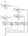
- FIG. 3 is a flowchart for determining the start of off timing adjustment control of the switching element.
- FIG. 4 is a flowchart in which the transition from PWM control to off timing adjustment control is determined.
- FIG. 5 is a flowchart showing an operation at the time of increase of the input voltage of the inverter circuit.
- FIG. 6 is a flowchart showing off timing adjustment control.
- FIG. 1 is a block diagram of a motor drive device according to a first embodiment of the present disclosure.
- FIG. 2A is a diagram showing drive waveforms and a timing chart of the motor drive device according to Embodiment 1.
- FIG. 2B is a diagram
- FIG. 7A is a diagram showing a terminal voltage waveform of the section C1 in FIG. 2A.
- FIG. 7B is a diagram showing a terminal voltage waveform of the section F1 in FIG. 2A.
- FIG. 7C is a diagram showing a terminal voltage waveform of the section C3 in FIG. 2B.
- FIG. 7D is a diagram showing a terminal voltage waveform of the section F2 in FIG. 2B.
- FIG. 8A is a diagram showing phase current waveforms of the brushless DC motor when PWM control is performed.
- FIG. 8B is a diagram showing a phase current waveform of the brushless DC motor when the on-time ratio is 100%.
- FIG. 9 is a block diagram of a motor drive device of Patent Document 1.
- FIG. 10 is a block diagram of a motor drive device of Patent Document 2.
- FIG. 9 is a block diagram of a motor drive device of Patent Document 1.
- FIG. 10 is a block diagram of a motor drive device of Patent Document 2.
- the driveable region can be expanded in the case of high load and high speed by advancing the turn-on of the switching element and widening the power supply section to the brushless DC motor to 120 degrees or more.
- a loss occurs with the on / off switching operation of the switching element by PWM control.
- the switching operation at high frequency by PWM control is accompanied by an increase in motor iron loss.
- the timing at which the control is possible is commutation (for example, in a 4-pole motor, 12 times during one rotation of the motor) Limited to Therefore, the response is delayed when the input voltage to the inverter circuit suddenly changes (especially when it rises) due to a disturbance or the like.
- the excessive application of the voltage to the brushless DC motor results in a significant delay phase. Therefore, the brushless DC motor may be out of step, or the permanent magnet of the rotor may be demagnetized and damaged due to the generation of a large current at the time of synchronization, thereby reducing the reliability of the brushless DC motor.
- a motor drive device includes: a brushless DC motor having a rotor; an inverter circuit that supplies electric power to the DC brushless DC motor including six switching elements; It has a position detection part to detect, and a PWM control part which adjusts a voltage applied to a brushless DC motor by turning on and off the switching element at high frequency.
- the motor drive apparatus further detects an input voltage of the inverter circuit and a conduction phase control unit that sets the conduction state of each phase of the brushless DC motor while maximizing the on time ratio of the switching element by PWM control.
- the PWM control unit sets an on-time time ratio of PWM control in accordance with a change in input voltage of the inverter circuit.
- the PWM control unit controls the on time of the switching element so that the voltage applied to the brushless DC motor does not change before and after the change in the input voltage of the inverter circuit. It may be configured to set the duty ratio.
- the motor drive device further includes a rectifier circuit that converts an AC voltage to a DC voltage, a smoothing circuit that converts the output of the rectifier circuit to a DC voltage, full-wave rectification and voltage doubling of the rectifier circuit.
- the PWM control unit may be configured to lower the on-time ratio of the switching element when switching from full-wave rectification to voltage doubler rectification is performed by the switching unit.
- the brushless DC motor of the above-described motor drive device may drive a compressor provided in a refrigeration cycle.
- the COP Coefficient Of Performance
- the above-mentioned motor drive device may be used.
- FIG. 1 shows a block diagram of a motor drive device according to a first embodiment of the present disclosure.
- Motor drive device 30 includes an inverter circuit 3 and a DC brushless DC motor 4. Further, a DC voltage is supplied to the motor drive device 30, for example, by the converter circuit 2 or the like.
- an alternating current power supply 1 is a general commercial power supply.
- the trademark power supply has an effective value of 100 V and a power supply frequency of 50 Hz or 60 Hz.
- Converter circuit 2 converts AC power supply 1 into a DC voltage.
- Converter circuit 2 in FIG. 1 includes a rectifier circuit 2a and a smoothing circuit 2b. Further, converter circuit 2 includes a switch (switching unit) 2 c that switches the output voltage.
- the rectifier circuit 2a is configured by bridge connection of four diodes.
- the smoothing circuit 2 b is configured of a capacitor.
- the switch 2 c is configured to switch the output voltage of the converter circuit 2 in two stages of voltage doubler rectification and full wave rectification.
- the inverter circuit 3 is composed of six switching elements 3a to 3f.
- a MOSFET is used for each of the switching elements 3a to 3f.
- the switching elements 3a to 3f are connected in a three-phase bridge. By turning on and off any switching element, the input DC voltage of the inverter circuit 3 is converted into a three-phase AC voltage.
- the brushless DC motor 4 is configured to include a stator and a rotor having permanent magnets.
- the stator has three stator windings corresponding to three phases.
- the brushless DC motor 4 is driven by three-phase AC power supplied from the inverter circuit 3.
- the motor drive device 30 also has an input voltage detection unit 15 that detects an input voltage to the inverter circuit 3.
- the input voltage detection unit 15 acquires voltage information from an input voltage detection circuit 14 described later, detects an input voltage to the inverter circuit 3, and inputs the detected input voltage to the PWM control unit 11.
- a plurality of resistors connected in series are connected to the output portion of the smoothing circuit 2b, and the voltage detection circuit 14 is configured to extract a voltage applied to both ends of any resistor.
- the motor drive device 30 has a position detection unit 5.
- the position detection unit 5 detects the magnetic pole position of the brushless DC motor 4. In the first embodiment, position detection is performed by detecting the zero crossing point of the induced voltage generated in the stator winding of the brushless DC motor 4 based on the terminal voltage of the motor. The induced voltage is generated by the rotation of the rotor of the brushless DC motor 4.
- the position detection method may be a method using a position sensor such as a Hall IC or a method based on current detection using a current sensor or the like.
- the motor drive device 30 may have the speed detection unit 6.
- the speed detection unit 6 detects the driving speed of the brushless DC motor 4 from the output signal of the position detection unit 5.
- the driving speed of the brushless DC motor 4 is calculated based on the cycle of the zero cross point of the induced voltage generated in the stator winding of the brushless DC motor 4.
- the motor drive device 30 may have the speed error detection unit 7.
- the speed error detection unit 7 detects the difference between the driving speed of the brushless DC motor 4 obtained by the speed detection unit 6 and the target speed.
- the motor drive device 30 has an energized phase control unit 8.
- the energization phase control unit 8 sets which stator winding of the three stator windings of the brushless DC motor 4 is to be supplied with power based on the signal from the position detection unit 5. Electric power is supplied to each stator winding in a range of 90 degrees or more and 150 degrees or less.
- the energized phase control unit 8 includes an on timing control unit 9 and an off timing control unit 10.
- the on-timing control unit 9 sets timing (hereinafter, on-timing) to turn on the switching elements 3a to 3f.
- the off-timing control unit 10 sets the timing (hereinafter, off-timing) to turn off the switching elements 3a to 3f. That is, the on timing and the off timing of each of the switching elements 3a to 3f of the inverter circuit 3 are set individually.
- the energization phase control unit 8 sets the energization state of each phase as described above.
- the motor drive device 30 has a PWM control unit 11.
- the PWM control unit 11 adjusts the three-phase AC output voltage of the inverter circuit 3 by PWM control. Thereby, the brushless DC motor 4 is controlled to drive at the target speed.
- the on-time ratio (Duty Ratio) of PWM control of the brushless DC motor 4 is “(minimum value of electrical angle when power is supplied to the stator winding of the brushless DC motor) ⁇ 2- (electrical angle 120 degrees
- the off timing control unit 10 determines that the on time ratio of the PWM control unit 11 is the maximum value.
- the off timing of the switching element is advanced so as to be 100%.
- the off timing control unit 10 advances the off timing of the switching element and the on time ratio is Make it 100%.
- the off timing and the on timing be gradually changed.
- the change of the off timing may be divided into a plurality of times and may be advanced from the previous off timing.
- the off timing and the on timing may be changed within one control cycle.
- the speed control of the brushless DC motor 4 is performed by adjusting the on-time ratio by the PWM control unit 11 when the brushless DC motor 4 is driven at the above-described on-time ratio of PWM control or less. Limited. Therefore, PWM control is performed when the brushless DC motor 4 is driven in a relatively low load or low speed state, such as at startup, low speed drive, low load drive, and double voltage input at the start of the brushless DC motor 4. To be done.
- the off phase and on timing of the switching element are controlled by the conduction phase control unit 8 so that the on time ratio of PWM control is 100%.
- the drive speed of the brushless DC motor 4 is controlled while the on-time ratio of the switching element by PWM control is maximized (100% in the stable drive state in the present embodiment).
- the waveform synthesis unit 12 illustrated in FIG. 1 synthesizes the PWM signal generated by the PWM control unit 11 and the signal generated by the conduction phase control unit 8.
- the drive unit 13 turns on or off the switching elements 3a to 3f of the inverter circuit 3 based on the signal synthesized by the waveform synthesis unit 12. This generates an arbitrary three-phase AC voltage.
- the generated three-phase AC voltage is supplied to the brushless DC motor 4 to drive the brushless DC motor 4.
- the on-time ratio of the PWM control is instantaneously reduced so that the input voltage of the brushless DC motor 4 does not change significantly, and the brushless by PWM control at any conduction angle.
- the DC motor 4 is driven.
- the off timing control unit 10 of the conduction phase control unit 8 advances the off timing of the switching element so that the on time ratio of the PWM control becomes 100%.
- the on-time ratio of the PWM control is increased according to the degree of decrease of the input voltage of the inverter circuit 3 when the PWM control is performed.
- the change of the input voltage of the brushless DC motor 4 is suppressed by adjusting the on time ratio of the PWM control.
- the on-time ratio is driven at 100%, this approach can not be addressed.
- the input voltage of the inverter circuit 3 drops sharply due to an instantaneous power failure or the like, electric power is supplied to the brushless DC motor 4 by the charge stored in the smoothing circuit 2b.
- a rapid voltage drop is avoided, so it is difficult for the brushless DC motor 4 to be out of step due to the rapid voltage drop. Therefore, when the on-time ratio of PWM control is 100%, control for suppressing the input voltage change of the inverter circuit 3 is not essential.
- FIG. 1 shows an example in which the motor drive device 30 described above is used for the compressor 17.
- the compressor 17 constitutes a refrigeration cycle together with the condenser 18, the pressure reducer 19 and the evaporator 20.
- the refrigerator 21 is shown as an example of the refrigerating cycle apparatus using a refrigerating cycle.
- the compressor 17 has a brushless DC motor 4 and a compression element 16.
- the brushless DC motor 4 and the compression element 16 are housed in the same closed container.
- the compression element 16 of the compressor 17 is connected to the shaft of the rotor of the brushless DC motor 4, sucks the refrigerant gas, and compresses and discharges the sucked refrigerant gas.
- the refrigerant gas discharged from the compressor 17 is again drawn into the compressor 17 through the condenser 18, the pressure reducer 19 and the evaporator 20. This constitutes a refrigeration cycle. Since heat is released in the condenser 18 and heat absorption is performed in the evaporator 20 during the refrigeration cycle, the refrigeration cycle apparatus can perform heating or heat absorption.
- a blower is used for the condenser 18 and the evaporator 20 as needed. This promotes heat exchange in the condenser 18 and the evaporator 20.
- the refrigerator 21 has the food storage room 23 enclosed by the heat insulation wall 22, as shown in FIG.
- the evaporator 20 is used to cool the inside of the food storage room 23.
- FIG. 2A and FIG. 2B are drive waveforms and timing charts of the motor drive device according to the present embodiment.
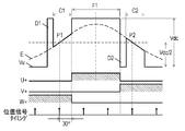
- FIG. 2A is a drive waveform and timing chart in the case of general energization at an electrical angle of 120 degrees.
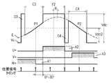
- FIG. 2B is a drive waveform and a timing chart in a state in which the off timing of the switching element is adjusted.
- FIGS. 2A and 2B the induced voltage generated by the rotation of the brushless DC motor 4 is shown as Vu, which is the terminal voltage of the U phase among the E phases (U phase, V phase and W phase). Moreover, FIG. 2A and FIG. 2B have shown only the waveform about U phase.
- the waveforms of the induced voltage and the terminal voltage of the V phase and the W phase are waveforms of the same shape in which the phases are respectively shifted by 120 degrees from the waveforms of the induced voltage and the terminal voltage of the U phase.
- pressure side of the inverter circuit 3 is each shown as U +, V +, W +.
- the drive signals of the switching elements 3d, 3e, 3f connected to the low voltage side of the inverter circuit 3 have respective phases from the drive signals of the switching elements 3a, 3b, 3c on the high voltage side corresponding to the switching elements 3d, 3e, 3f. It will be 180 degrees off.
- the position detection unit 5 detects the position of the rotor of the brushless DC motor 4 directly or indirectly. Based on the detected rotor position information, timing (not shown) to switch the energized phase in the stator winding is adjusted.
- the position detection unit 5 detects the relative position of the magnetic poles of the rotor. Specifically, the position detection unit 5 detects the zero cross point of the induced voltage as a position signal.
- C1 and C2 are sections where voltage is not applied to the corresponding stator winding (in U phase shown in FIGS. 2A and 2B, both switching elements 3a and 3d are turned off) , C3, and C4) detect points (P1, P2) at which the magnitude relationship between the induced voltage appearing in the stator winding and the half of the inverter input voltage Vdc is inverted.
- the position signal of the zero crossing point is detected twice for each phase per electrical angle cycle. That is, in all three phases, position signals are detected six times in total at every electrical angle of 60 degrees.
- the induced voltage appears in the stator winding in the section C1 to C4 only during the period when the switching element of the other phase is on, that is, the ON period of the switching element by PWM control. Therefore, the turn-off of the switching element is controlled to be performed earlier than the turn-on, whereby the power supply interval to the brushless DC motor 4 is controlled to be short. As a result, the number of times the switching element is turned on and off due to PWM control is reduced, so that the loss of the inverter circuit 3 is suppressed.
- the on time of the switching element by PWM control becomes longer.
- the period during which the position detection unit 5 can acquire the position detection signal of the zero cross point is extended. Therefore, the accuracy of position detection by the position detection unit 5 is improved.
- the off timing of the switching element is from immediately after the position detection of the zero cross point (P1) to the time when an electrical angle of 30 degrees elapses ( Range). This enables reliable commutation based on the result of position detection of the zero cross point (P1). Further, since the drive waveform is in the lead phase with respect to the induced voltage, the occurrence of the torque drop due to the delay phase is avoided.
- the power supply section of the three-phase stator winding is 90 degrees or more. And it is adjusted to 120 degrees or less.
- a larger advance angle B 1/2 of the electrical angle of the non-powered section
- the load is the maximum load that can be driven by the conduction at 120 °.
- the off timing is fixed when an electrical angle of 30 degrees elapses, and the on timing is advanced to a maximum of an electrical angle of 30 degrees while the on time ratio of PWM control is 100%. That is, commutation occurs simultaneously with the acquisition of the position detection signal.
- the conduction angle of each phase can be expanded to an electrical angle of 150 degrees, and the range of loads that can be driven by the motor drive device 30 can be expanded.
- the input current of the brushless DC motor 4 increases by about 17% at the maximum as compared with the case of energization at an electrical angle of 120 degrees.
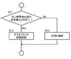
- FIG. 3 is a flowchart for determining the start of off timing adjustment control of the switching element.
- the on-time ratio of the switching element generated by the PWM control unit 11 is larger than a predetermined value (S11). If the on time ratio is larger than the predetermined value (Yes in S11), the off timing adjustment control described later is performed (S12). When the on-time ratio is equal to or less than the predetermined value (No in S11), PWM control is performed (S13).
- the minimum value of the on section of each switching element is set to an electrical angle of 90 degrees.
- the predetermined value of the on-time time ratio is set to 50% from ⁇ (90 degrees ⁇ 2) ⁇ 120 degrees ⁇ / 120 degrees.
- the predetermined value of the on time ratio is set to an appropriate value in consideration of the application of the motor drive device.
- the off-timing adjustment control of the switching element is started when the ratio is greater than or equal to the predetermined on-time period.
- off timing adjustment control and PWM control are used in combination.
- the drive speed is extremely low, such as when the brushless DC motor 4 is started, or when the load is extremely low at low speed driving, or when the load is relatively light at doubled voltage input or at low speed, etc.
- a failure in starting of the brushless DC motor 4 due to an extremely short power supply section to the stator winding, an unstable operating condition, or an extreme torque drop can be prevented. Therefore, the brushless DC motor 4 can be stably driven under any load condition.
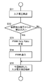
- FIG. 4 is a flowchart in which the transition from PWM control to off timing adjustment control is determined.
- the off timing of the switching element is advanced by an arbitrary time (S21). Further, speed control is performed by PWM control (S22).
- the off timing is advanced, as described above, it may be divided into a plurality of times and may be advanced from the previous off timing.
- the off timing of the switching element is advanced (S21)
- the power supply section to the brushless DC motor 4 becomes short. Therefore, the PWM control will increase the on time ratio.
- the on-time ratio reaches 100% (No in S23)
- the on-time ratio is maintained at 100% (S24). That is, in this case, the PWM control is not performed. Further, the off timing of the switching element is adjusted (S25). That is, when the on-time ratio becomes 100%, the PWM control is shifted to the off-timing adjustment control. Thereby, the drive speed of the brushless DC motor 4 is controlled so that the brushless DC motor 4 is driven at the target speed.
- on timing control when the off timing of the switching element has reached the time when an electrical angle of 30 degrees (that is, a state in which current is supplied at 120 degrees) has elapsed after the position detection of the zero cross point, on timing control is performed. It is also good. In the on-timing control, the on-timing of the switching element is advanced up to an electrical angle of 30 degrees. As a result, the drivable area of the brushless DC motor 4 is expanded, and the brushless DC motor 4 is appropriately driven at the target speed.
- FIG. 5 is a flow chart showing the operation when the input voltage of the inverter circuit 3 rises.
- the input voltage detection unit 15 detects the input voltage of the inverter circuit 3 (S31).
- the on time ratio of PWM control according to the detected input voltage is calculated (S33).
- the on-time time ratio is calculated so that the applied voltage of the brushless DC motor 4 becomes equal before and after the voltage fluctuation occurs.
- “on-time ratio [%] (previous detection voltage [V] / current detection voltage [V]) ⁇ 100” is calculated.
- the PWM control unit 11 outputs the PWM waveform at the calculated on-time ratio (S34). Also, the detected value of the input voltage of the inverter circuit 3 at this time is stored as the previous value (S35).
- the on-time ratio of PWM control is instantaneous such that the input voltage to the brushless DC motor 4 becomes equal before and after the change of the input voltage of the inverter circuit 3 Calculated and output.
- the rapid change of the input voltage to the brushless DC motor 4 is suppressed, and the step out of the brushless DC motor 4 is avoided.
- the generation of an overcurrent which causes demagnetization of the permanent magnet of the rotor is prevented.
- the brushless DC motor 4 can be switched without stopping once. it can. Therefore, it is possible to provide a motor drive device that is very easy to use.
- the detection cycle of the input voltage of the inverter circuit 3 is preferably a PWM timer cycle in order to improve the response to the voltage fluctuation. However, it is set in consideration of the calculation ability of the processor to be used and the A / D conversion speed.
- FIG. 6 is a flowchart showing off timing adjustment control.
- the deviation between the driving speed of the brushless DC motor 4 detected by the speed detection unit 6 and the target speed is detected by the speed error detection unit 7.
- the determination as to whether or not the off timing of the switching element can be advanced is performed as follows.
- the off timing of the switching element is immediately after the position detection of the zero cross point, it is determined that the off timing can not be further advanced.
- the minimum value of the power supply section to each stator winding is 90 degrees of electrical angle.
- the off timing of the switching element is between immediately after the detection of the zero cross point position and the time when the electrical angle is 30 degrees It is determined whether there is any (S46).
- the off timing of the switching element is earlier than the time when the electrical angle of 30 degrees has passed (Yes in S46), the off timing of the switching element is delayed (S47). As a result, the power supply section to the stator winding of the brushless DC motor 4 is increased, and the speed control is performed so that the driving speed of the brushless DC motor 4 is increased.
- the off timing of the off switching element is after the lapse of the electrical angle of 30 degrees (No in S46)
- the applied voltage phase is delayed with respect to the induced voltage.
- the on timing of the switching element is advanced (S48).
- the power supply section to the stator winding is increased, and speed control is performed such that the driving speed of the brushless DC motor 4 is increased.
- the upper limit of the range in which the on-timing of the switching element can be advanced is immediately after the position detection of the zero cross point.
- the maximum value of the power supply section to the stator winding when the off timing of the switching element is immediately after the position detection of the zero cross point is 150 degrees of electrical angle.
- the current flowing through the brushless DC motor 4 increases by about 17% with respect to the current at the electrical angle of 120 degrees. Accordingly, the output range of the brushless DC motor 4 is also expanded.
- the advance angle is set to 0 degrees. Therefore, when the conduction angle is 120 degrees in electrical angle, the off timing and on timing of the switching element coincide with each other at an electrical angle of 30 degrees after the position detection of the zero cross point.
- the motor drive device 30 can optimally drive various motors, including an IPM motor (Interior Permanent Magnet Motor).
- IPM motor Interior Permanent Magnet Motor
- permanent magnets are embedded inside the stator of the IPM motor. For this reason, in order to realize the optimum drive of the IPM motor, it is necessary to provide an appropriate advance angle.
- the range of the off timing adjustment of the switching element and the range of the on timing adjustment are set as follows.
- the off timing of the switching element is in the range from immediately after the detection of the position of the zero cross point to the time when ((electrical angle 30 degrees) ⁇ (advance angle)) has elapsed.
- the on timing of the switching element is the time when ((electrical angle 30 degrees) ⁇ (advance angle)) has elapsed after the position detection of the zero cross point.
- the off timing of the switching element is adjusted in the range from immediately after the position detection of the zero cross point to the time of the electrical angle of 20 degrees
- the on timing is the position detection of the zero cross point It is adjusted when the electrical angle of 20 degrees has passed.
- the sum of the electrical angle from the time of detecting the position of the zero cross point to the off timing and the electrical angle from the time of detecting the position of the zero cross point to the on timing is set to 60 degrees or less.
- the off timing is adjusted in an arbitrary range from the on timing to the time when the electrical angle is 0 degrees to 30 degrees.
- the advance angle, the on timing, and the off timing can be freely set in the range from immediately after the detection of the position of the zero cross point to the time when the electrical angle of 30 degrees has elapsed.
- ON section (energization angle) of each switching element when the advance angle is added is adjusted in the range of “(electrical angle 90 degrees) + (advance angle)” to 120 electrical angle.
- the on timing and off timing of the switching element may be adjusted as follows.
- the off timing of the switching element is adjusted when "(electrical angle 30 degrees)-(advance angle)" has elapsed after the position detection of the zero cross point. Further, the on-timing of the switching element is adjusted in the range from immediately after the detection of the position of the zero cross point to the time when the "electrical angle 30 degrees-advance angle” has elapsed. As a result, the on section of each switching element can be adjusted within the range of 120 ° electrical angle to “(electrical angle 150) ⁇ (advance angle)”.
- the motor drive device 30 of the present embodiment can drive the brushless DC motor 4 in a wide range from the low speed and low load state to the high speed and high load state.
- FIGS. 7A and 7B respectively show terminal voltages of the section C1 and the section F1 in FIG. 2A.
- FIGS. 7C and 7D respectively show terminal voltages of the section C3 and the section F2 in FIG. 2B.
- a high frequency PWM carrier frequency component (period f) is superimposed on the waveform in the case of PWM control shown in FIG. 2A.
- FIG. 8A is a diagram showing phase current waveforms of the brushless DC motor when PWM control is performed.
- FIG. 8B is a diagram showing a phase current waveform of the brushless DC motor when the on-time ratio is 100%.
- FIG. 8A shows a waveform in the case of energization at an electrical angle of 120 degrees. As shown in FIG. 8A, high-frequency current components accompanying switching on and off of the switching element by PWM control are superimposed on the phase current waveform when PWM control is performed. This high frequency current component causes the motor iron loss.
- Refrigerator using motor drive A refrigeration cycle apparatus using a compressor 17 driven by the motor drive device 30 configured as described above will be described.
- a refrigerator will be described as an example of the refrigeration cycle apparatus.
- the switching operation of switching elements on and off at high frequency by PWM control is not performed. Instead, the drive timing is controlled by adjusting the on timing or off timing of the switching element such that the on time ratio of the PWM control is 100%. As a result, the occurrence of switching loss of the inverter circuit 3 due to PWM control is avoided, and the circuit efficiency of the inverter circuit 3 is significantly improved.
- a MOSFET is used as a switching element of the inverter circuit 3.
- the MOSFET does not have a PN junction in the path of the output current when it is on. For this reason, the on-state loss, especially at low current output of the MOSFET, is very low compared to that of other power devices such as IGBTs.
- the refrigerator is driven at low speed and low load during most of the time of day, and the current flowing to the brushless DC motor 4 is small. Therefore, when the motor drive device 30 of the present disclosure is used for the compressor 17 of the refrigerator as described above, the power consumption of the refrigerator is effectively reduced by using the MOSFET as the switching element of the inverter circuit 3 .
- the phase current flowing in the stator winding of the brushless DC motor 4 is high frequency. It can be avoided that current components are superimposed. As a result, motor iron loss can be significantly reduced, and motor efficiency can be improved.
- PWM control switching operation of the switching element is generally performed at a PWM frequency of about 1 kHz to about 20 kHz, and noise due to a frequency component of the switching operation is generated. It is very important to improve the silent performance of the refrigerator, since the refrigerator is operated all day regardless of day and night. In the motor drive device 30 of the present embodiment, since the on-time ratio is set to 100%, generation of noise due to PWM control can be avoided, and noise reduction performance of the refrigerator can be improved.
- the refrigerator needs to delay restart until the pressure difference between the low pressure side and the high pressure side is balanced, when the compressor 17 is stopped once.
- the motor drive device 30 of the present embodiment can suppress the fluctuation of the input voltage of the brushless DC motor 4 even when the input voltage of the inverter circuit 3 sharply rises, and can continue the stable driving of the brushless DC motor 4. Therefore, there is no temperature rise in the refrigerator due to the stop of the compressor 17, and a stable cooling state can be maintained.
- the compressor 17 is driven at high speed to increase the refrigeration capacity as the load on the refrigerator increases, the loss of cooling in the refrigerator due to the stop of the compressor 17 is avoided while the operation of the brushless DC motor is performed.
- the input voltage can be switched to the voltage doubling.
- the motor drive device can improve circuit efficiency and improve the efficiency of the brushless DC motor, as well as improve the reliability. In addition, it is possible to reduce the driving noise of the brushless DC motor and the vibration of the device. Therefore, the present invention can be applied to any device in which a brushless DC motor is used, such as a refrigerator, an air conditioner, a washing machine, a pump, a fan, a fan, and a vacuum cleaner.
Landscapes
- Engineering & Computer Science (AREA)
- Chemical & Material Sciences (AREA)
- Combustion & Propulsion (AREA)
- Physics & Mathematics (AREA)
- Mechanical Engineering (AREA)
- Thermal Sciences (AREA)
- General Engineering & Computer Science (AREA)
- Power Engineering (AREA)
- Control Of Motors That Do Not Use Commutators (AREA)
- Devices That Are Associated With Refrigeration Equipment (AREA)
Abstract
回転子を有するブラシレスDCモータ(4)と、6個のスイッチング素子(3a~3f)を含んで構成され、ブラシレスDCモータ(4)に電力を供給するインバータ回路(3)と、回転子の位置を検出する位置検出部(5)と、スイッチング素子(3a~3f)を高周波数でオンおよびオフすることで、ブラシレスDCモータ(4)に印加される電圧を調整するPWM制御部(11)と、PWM制御によるスイッチング素子(3a~3f)のオン時間時比率が最大となるようにしつつ、ブラシレスDCモータ(4)の各相の通電相を決める通電相制御部(8)と、インバータ回路(3)の入力電圧を検出する入力電圧検出部(15)を有し、PWM制御部(11)は、インバータ回路(3)の入力電圧の変化に応じて、PWM制御のオン時間時比率を設定する。
Description
本開示は、インバータ制御によりブラシレスDCモータを駆動するモータ駆動装置、および、これを用いた冷蔵庫に関する。
従来、この種のブラシレスDCモータの駆動装置においては、ブラシレスDCモータの各相の通電状態が、PWM(Pulse Width Modulation)制御によって制御される。
具体的には、PWM制御の矩形波によって、各相の通電区間が、基本的に120度となるように制御されて、ブラシレスDCモータが駆動される。また、PWM制御のオンデューティ(Duty Ratio)が100%となったときに、通電区間が120度以上に拡張される。これにより、ブラシレスDCモータの、高速かつ高負荷の場合における、駆動可能領域が拡張される(例えば、特許文献1参照)。
図9は、特許文献1のモータ駆動装置のブロック図を示している。図9に示すように、インバータ回路103は、スイッチング素子103a~103fによって構成される。各スイッチング素子103a~103fが、オフからオンに移行する際に、オンタイミング制御手段104aにより、進角制御が行われる。一方、各スイッチング素子103a~103fが、オンからオフに移行する際には、オフタイミング制御手段104bによる進角制御は行われない。これにより、オーバーラップ通電が行われる。
また、従来の他のモータ駆動装置においては、モータに供給される電力が目標電力値となるように、スイッチング素子の通電角および進角、インバータへの入力直流電圧が制御される。これにより、モータ駆動装置の高出力化が実現されるとともに、モータの高回転が可能となる。また、モータ駆動装置の損失が低減されている(例えば、特許文献2参照)。
図10は、特許文献2のモータ駆動装置の駆動制御手段201のブロック図を示している。図10に示すように、ブラシレスDCモータの駆動制御手段201は、駆動電力を検出する電力検出手段202と、通電パルス信号生成制御手段203と、を有する。通電パルス信号生成手段203は、インバータの駆動信号パターンの生成、およびインバータ入力電圧の設定を行う。そして、駆動電力が目標設定電力値に一致するように、インバータの入力電圧値、通電角、および進角が制御される。
しかしながら、従来のモータ駆動装置においては、高効率化および信頼性の向上について、未だ改善の余地がある。
本開示は、モータ駆動装置の低損失化による機器の高効率化と、信頼性の向上を図ることを目的とする。また、インバータ回路の入力電圧が大きく変動した場合も、安定したブラシレスDCモータの駆動を可能として、ブラシレスDCモータの信頼性を向上することを目的とする。
具体的には、本開示のモータ駆動装置は、回転子を有するブラシレスDCモータと、6個のスイッチング素子を含んで構成され、ブラシレスDCモータに電力を供給するインバータ回路と、回転子の位置を検出する位置検出部と、スイッチング素子を高周波数でオンおよびオフすることで、ブラシレスDCモータに印加される電圧を調整するPWM制御部と、を有する。モータ駆動装置は、さらに、PWM制御によるスイッチング素子のオン時間時比率が最大となるようにしつつ、ブラシレスDCモータの各相の通電状態を設定する通電相制御部と、インバータ回路の入力電圧を検出する入力電圧検出部と、を有する。PWM制御部は、インバータ回路の入力電圧の変化に応じて、PWM制御のオン時間時比率を設定するように構成されている。
このような構成により、インバータ回路によって、ブラスレスDCモータの損失を低減させ、ブラシレスDCモータの高効率化を図ることができる。また、インバータ回路の入力電圧が大きく変動した場合も、安定したブラシレスDCモータの駆動ができるため、ブラシレスDCモータの信頼性を向上することができる。
(本開示の基礎となった知見)
本開示の発明者らは、モータ駆動装置の性能および信頼性の向上のために、鋭意検討した結果、以下の知見を得た。
本開示の発明者らは、モータ駆動装置の性能および信頼性の向上のために、鋭意検討した結果、以下の知見を得た。
前述の特許文献1の構成では、スイッチング素子のターンオンを早めてブラシレスDCモータへの電力の供給区間を120度以上に広げることで、高負荷かつ高速の場合における駆動可能領域の拡張が可能となる。しかしながら、低負荷かつ低速の場合における駆動領域においては、PWM制御によるスイッチング素子のオンおよびオフのスイッチング動作に伴って、損失が発生する。また、PWM制御による高周波数でのスイッチング動作には、モータ鉄損の増加が伴う。
また、上記特許文献2に記載された、ブラシレスDCモータの通電角の増減による速度の制御では、当該制御が可能なタイミングが転流時(例えば、4極モータでは、モータ1回転中12回)に限られる。従って、外乱などによって急激にインバータ回路への入力電圧が変動した場合(特に、上昇した場合)、応答が遅れる。また、ブラシレスDCモータへの電圧の過剰印加によって、大幅な遅れ位相の状態となる。従って、ブラシレスDCモータの脱調が発生し、または、脱調時における大電流の発生による回転子の永久磁石の減磁破損が発生するなどして、ブラシレスDCモータの信頼性が低下する。
これらの新規な知見に基づき、本発明者らは、以下の開示をするに至った。
本開示の一態様に係るモータ駆動装置は、回転子を有するブラシレスDCモータと、6個のスイッチング素子を含んで構成され、DCブラシレスDCモータに電力を供給するインバータ回路と、回転子の位置を検出する位置検出部と、スイッチング素子を高周波数でオンおよびオフすることで、ブラシレスDCモータに印加される電圧を調整するPWM制御部と、を有する。モータ駆動装置はさらに、PWM制御によるスイッチング素子のオン時間時比率が最大となるようにしつつ、ブラシレスDCモータの各相の通電状態を設定する通電相制御部と、インバータ回路の入力電圧を検出する入力電圧検出部と、を有し、PWM制御部は、インバータ回路の入力電圧の変化に応じて、PWM制御のオン時間時比率を設定する。
このような構成により、PWM制御によるスイッチング素子のスイッチング損失を低減し、モータ駆動装置の高効率化を図ることができる。また、PWM制御による高周波電流を抑制できるため、モータ鉄損を低減することができる。また、入力電圧が大きく上昇した場合であっても、ブラシレスDCモータへ印加される電圧の急激な上昇を抑えることができるため、ブラシレスDCモータの脱調、および、大電流の発生を抑制することができる。
本開示の他の一態様に係るモータ駆動装置においては、PWM制御部は、インバータ回路の入力電圧の変化の前後で、ブラシレスDCモータへ印加される電圧が変化しないように、スイッチング素子のオン時間時比率を設定するように構成されてもよい。
このような構成により、インバータ回路の入力電圧が急上昇した場合でも、ブラシレスDCモータの速度変動は極めて小さくすることができるため、速度変動による振動および騒音を抑制し、ブラシレスDCモータの信頼性の向上を図ることができる。
本開示の他の一態様に係るモータ駆動装置は、さらに、交流電圧を直流電圧に変換する整流回路と、整流回路の出力を直流電圧にする平滑回路と、整流回路を全波整流および倍電圧整流の間で切り替える切替部と、を有し、切替部により全波整流から倍電圧整流に切り替えられると、PWM制御部はスイッチング素子のオン時間時比率を下げるように構成されてもよい。
このような構成により、ブラシレスDCモータが低速かつ低負荷の状態で駆動される場合には、全波整流入力によってインバータ損失を抑制した高効率な駆動を行い、ブラシレスDCモータが高速かつ高負荷の状態で駆動される場合には、倍電圧入力によって高出力駆動を行うことができ、ブラシレスDCモータの駆動状態に応じた最適な駆動が可能となる。また、全波整流から倍電圧整流への切り替えに伴ってインバータ回路の入力電圧が上昇した場合であっても、急激なブラシレスDCモータの速度変動を抑制でき、信頼性の高いモータ駆動装置を提供することができる。
本開示の他の一態様に係るモータ駆動装置は、上述のモータ駆動装置のブラシレスDCモータが、冷凍サイクルに設けられた圧縮機を駆動するものであってもよい。
このような構成により、圧縮機のCOP(Coefficient Of Performance)を向上させることができるとともに、効率が高く、かつ、信頼性の高い冷凍サイクル装置を提供できる。
また、本開示に係る冷蔵庫においては、上述のモータ駆動装置が用いられてもよい。
これにより、消費電力が低く、かつ、信頼性の高い冷蔵庫を提供できる。また、高周波数でのスイッチング素子のスイッチング動作に伴う高周波数帯域の騒音が抑制され、冷蔵庫の静音化を図ることができる。
以下、本開示の実施の形態について、図面を参照しながら説明する。なお、本実施の形態によって本開示が限定されるわけではない。
(実施の形態1)
[1.全体構成]
図1は、本開示の実施の形態1におけるモータ駆動装置のブロック図を示している。
[1.全体構成]
図1は、本開示の実施の形態1におけるモータ駆動装置のブロック図を示している。
モータ駆動装置30は、インバータ回路3およびDCブラシレスDCモータ4を含む。また、モータ駆動装置30には、例えばコンバータ回路2などによって、直流電圧が供給される。
図1において、交流電源1は一般的な商用電源である。商標電源は、日本国内の場合、実効値が100Vであり、電源周波数が50Hzまたは60Hzである。
コンバータ回路2は、交流電源1を直流電圧に変換する。図1におけるコンバータ回路2は、整流回路2aおよび平滑回路2bを含む。また、コンバータ回路2は、出力電圧を切り替えるスイッチ(切替部)2cを含む。
整流回路2aは、4個のダイオードがブリッジ接続されて構成される。平滑回路2bは、コンデンサによって構成される。スイッチ2cは、コンバータ回路2の出力電圧を倍電圧整流および全波整流の2段階で切り替えるように構成されている。
インバータ回路3は、6個のスイッチング素子3a~3fで構成される。本実施の形態では、各スイッチング素子3a~3fには、それぞれMOSFETが用いられる。各スイッチング素子3a~3fは、3相ブリッジ接続されている。任意のスイッチング素子のオンおよびオフが切り替えられることで、インバータ回路3の入力直流電圧が3相交流電圧に変換される。
ブラシレスDCモータ4は、固定子、および、永久磁石を有する回転子を含んで構成される。固定子は、3相に対応する3つの固定子巻線を有する。ブラシレスDCモータ4は、インバータ回路3から供給される3相交流電力により駆動される。
また、モータ駆動装置30は、インバータ回路3への入力電圧を検出する入力電圧検出部15を有する。入力電圧検出部15は、後述する入力電圧検出回路14から電圧情報を取得して、インバータ回路3への入力電圧を検出し、検出した入力電圧をPWM制御部11に入力する。
電圧検出回路14は、例えば、直列に接続された複数の抵抗が平滑回路2bの出力部に接続されており、任意の抵抗の両端にかかる電圧を取り出すように構成されている。
また、モータ駆動装置30は、位置検出部5を有する。位置検出部5は、ブラシレスDCモータ4の磁極位置を検出する。本実施の形態1では、ブラシレスDCモータ4の固定子巻線に発生する誘起電圧のゼロクロスポイントが、モータの端子電圧に基づいて検出されることで、位置検出が行われる。誘起電圧は、ブラシレスDCモータ4の回転子の回転により発生する。なお、位置検出の方法としては、ホールIC等の位置センサを用いる方法、または、電流センサ等による電流検出に基づく方法等でもよい。
また、モータ駆動装置30は、速度検出部6を有していてもよい。速度検出部6は、位置検出部5の出力信号からブラシレスDCモータ4の駆動速度を検出する。本実施の形態では、ブラシレスDCモータ4の駆動速度は、ブラシレスDCモータ4の固定子巻線に生じる誘起電圧のゼロクロスポイントの周期に基づいて算出される。
また、モータ駆動装置30は、速度誤差検出部7を有していてもよい。速度誤差検出部7は、速度検出部6により得られたブラシレスDCモータ4の駆動速度と、目標速度との差を検出する。
また、図1に示すように、モータ駆動装置30は、通電相制御部8を有する。
通電相制御部8は、位置検出部5からの信号に基づいて、ブラシレスDCモータ4の3つの固定子巻線のうち、いずれの固定子巻線に電力を供給するかを設定する。各固定子巻線には、電気角90度以上かつ150度以下の範囲で、電力が供給される。
通電相制御部8は、オンタイミング制御部9と、オフタイミング制御部10と、を有する。オンタイミング制御部9は、各スイッチング素子3a~3fをターンオンするタイミング(以下、オンタイミング)を設定する。また、オフタイミング制御部10は、各スイッチング素子3a~3fをターンオフするタイミング(以下、オフタイミング)を設定する。つまり、インバータ回路3の各スイッチング素子3a~3fのオンタイミングおよびオフタイミングは、個別に設定される。
通電相制御部8は、以上のようにして、各相の通電状態を設定する。
[2.ブラシレスDCモータの駆動速度の制御]
図1に示すように、モータ駆動装置30は、PWM制御部11を有する。PWM制御部11は、PWM制御によって、インバータ回路3の3相交流出力電圧を調節する。これにより、ブラシレスDCモータ4は、目標速度で駆動するように制御される。
図1に示すように、モータ駆動装置30は、PWM制御部11を有する。PWM制御部11は、PWM制御によって、インバータ回路3の3相交流出力電圧を調節する。これにより、ブラシレスDCモータ4は、目標速度で駆動するように制御される。
ブラシレスDCモータ4のPWM制御のオン時間時比率(Duty Ratio)が、「(ブラシレスDCモータの固定子巻線へ電力が供給されるときの電気角の最小値)×2-(電気角120度)」を「電気角120度」で除した値より大きい状態においてブラシレスDCモータ4が駆動されている場合には、オフタイミング制御部10は、PWM制御部11のオン時間時比率がその最大値である100%となるように、スイッチング素子のオフタイミングを早める。
具体的には、例えば、ブラシレスDCモータ4へ電力が供給されるときの各スイッチング素子のオン区間が、オン区間の最小値である電気角90度の場合、(90度×2-120度)÷120度=50[%]となる。従って、PWM制御のオン時間時比率が50%以上の状態でブラシレスDCモータ4が駆動されている場合には、オフタイミング制御部10は、スイッチング素子のオフタイミングを早めて、オン時間時比率が100%となるようにする。
ここで、ブラシレスDCモータ4の動作状態の急激な変化を防ぐため、オフタイミングおよびオンタイミングの変更は、徐々に行われることが望ましい。例えば、オフタイミングの変更は、複数回に分けて、前回のオフタイミングから早められてもよい。ただし、オフタイミングおよびオンタイミングの変更は、一つの制御周期内で行われてもよい。
なお、PWM制御部11によるオン時間時比率の調整によってブラシレスDCモータ4の速度制御が行われるのは、ブラシレスDCモータ4が、上述したPWM制御のオン時間時比率以下で駆動されている場合に限られる。従って、PWM制御は、ブラシレスDCモータ4の起動時、低速駆動時、低負荷駆動時、および倍電圧入力時など、比較的、低負荷または低速の状態でブラシレスDCモータ4が駆動されている際に行われる。
それ以外の安定した駆動状態においては、PWM制御のオン時間時比率が100%となるように、通電相制御部8によってスイッチング素子のオフタイミングおよびオンタイミングが制御される。これによって、PWM制御によるスイッチング素子のオン時間時比率が最大(本実施の形態では、安定した駆動状態において、100%)になるようにしつつ、ブラシレスDCモータ4の駆動速度の制御が行われる。
なお、図1に示す波形合成部12は、PWM制御部11により生成されたPWM信号と、通電相制御部8により生成された信号とを合成する。ドライブ部13は、波形合成部12によって合成された信号を基に、インバータ回路3の各スイッチング素子3a~3fをオンまたはオフする。これによって、任意の3相交流電圧が生成される。生成された3相交流電圧がブラシレスDCモータ4に供給されることで、ブラシレスDCモータ4が駆動される。
[3.インバータ回路の入力電圧に基づく制御]
PWM制御部11は、入力電圧検出部15から入力されたインバータ回路3の入力電圧が、急峻に変動(特に上昇)したことを検出すると、入力電圧の変化(入力電圧が上昇した場合は、上昇率)に応じて、PWM制御によるインバータ回路3のスイッチング素子のオン時間時比率を設定する。インバータ回路3の入力電圧が上昇した場合は、オン時間時比率が低下される。PWM制御部11は、変更後のオン時間時比率の情報を、波形合成部12に出力する。
PWM制御部11は、入力電圧検出部15から入力されたインバータ回路3の入力電圧が、急峻に変動(特に上昇)したことを検出すると、入力電圧の変化(入力電圧が上昇した場合は、上昇率)に応じて、PWM制御によるインバータ回路3のスイッチング素子のオン時間時比率を設定する。インバータ回路3の入力電圧が上昇した場合は、オン時間時比率が低下される。PWM制御部11は、変更後のオン時間時比率の情報を、波形合成部12に出力する。
すなわち、インバータ回路3の入力電圧が急激に上昇すると、ブラシレスDCモータ4の入力電圧が大きく変化しないように、PWM制御のオン時間時比率が瞬時に下げられ、任意の通電角でPWM制御によるブラシレスDCモータ4の駆動が行われる。
その後、前述の通り、通電相制御部8のオフタイミング制御部10により、PWM制御のオン時間時比率が100%となるように、スイッチング素子のオフタイミングが進められる。
また、インバータ回路3の入力電圧が急激に低下すると、PWM制御が行われている場合はインバータ回路3の入力電圧の低下度合いに応じて、PWM制御のオン時間時比率が増加される。
このように、PWM制御のオン時間時比率を調整することによって、ブラシレスDCモータ4の入力電圧の変化が抑制される。しかし、オン時間時比率が100%で駆動されている場合は、この方法で対処することはできない。しかしながら、瞬時停電等でインバータ回路3の入力電圧が急激に低下した場合は、平滑回路2bに蓄積された電荷によって、ブラシレスDCモータ4に電力が供給される。これにより、急激な電圧の低下が回避されため、電圧の急激な低下によるブラシレスDCモータ4の脱調は発生しにくい。従って、PWM制御のオン時間時比率が100%の場合は、インバータ回路3の入力電圧変化を抑制するための制御は必須ではない。
[4.モータ駆動装置を用いた圧縮機]
図1は、上述のモータ駆動装置30が圧縮機17に用いられた例を示している。
図1は、上述のモータ駆動装置30が圧縮機17に用いられた例を示している。
図1に示すように、圧縮機17は、凝縮器18、減圧器19および蒸発器20とともに、冷凍サイクルを構成する。図1では、冷凍サイクルを利用した冷凍サイクル装置の例として、冷蔵庫21を示している。
圧縮機17は、ブラシレスDCモータ4および圧縮要素16を有する。ブラシレスDCモータ4および圧縮要素16は、同一の密閉容器に収納されている。
圧縮機17の圧縮要素16は、ブラシレスDCモータ4の回転子の軸に接続されており、冷媒ガスを吸入し、吸入された冷媒ガスを圧縮して吐出する。圧縮機17から吐出された冷媒ガスは、凝縮器18、減圧器19および蒸発器20を通って、再び圧縮機17に吸入される。これによって、冷凍サイクルが構成される。冷凍サイクル中の、凝縮器18では放熱が行われ、蒸発器20では吸熱が行われることから、冷凍サイクル装置は、加熱または吸熱を行うことができる。
なお、必要に応じて凝縮器18および蒸発器20に送風機が用いられる。これにより、凝縮器18および蒸発器20における熱交換が促進される。
また、冷蔵庫21は、図1に示すように、断熱壁22で囲われた食品貯蔵室23を有する。蒸発器20は、食品貯蔵室23内を冷却するために用いられる。
以上のように構成されたモータ駆動装置30について、以下その動作および作用を説明する。
[5.モータ駆動装置の動作]
[5-1.駆動波形およびタイミングチャート]
図2Aおよび図2Bは、本実施の形態におけるモータ駆動装置の駆動波形およびタイミングチャートである。
[5-1.駆動波形およびタイミングチャート]
図2Aおよび図2Bは、本実施の形態におけるモータ駆動装置の駆動波形およびタイミングチャートである。
図2Aは、一般的な、電気角120度での通電の場合の、駆動波形およびタイミングチャートである。図2Bは、スイッチング素子のオフタイミングが調整された状態における、駆動波形およびタイミングチャートである。
図2Aおよび図2Bにおいて、ブラシレスDCモータ4の回転により発生する誘起電圧がE、3相(U相、V相、およびW相)のうちのU相の端子電圧がVuとして示されている。また、図2Aおよび図2Bは、U相についての波形のみ示している。なお、V相およびW相の誘起電圧および端子電圧の波形は、U相の誘起電圧および端子電圧の波形から、それぞれ位相が120度ずれた、同形状の波形である。
図2Aおよび図2Bにおいて、インバータ回路3の高圧側に接続されたスイッチング素子3a、3b、3cについての駆動信号のタイミングチャートが、それぞれ、U+、V+、W+として示されている。インバータ回路3の低圧側に接続されたスイッチング素子3d、3e、3fの駆動信号は、スイッチング素子3d、3e、3fに対応する高圧側のスイッチング素子3a、3b、3cの駆動信号から、それぞれ位相が180度ずれたものとなる。
位置検出部5は、ブラシレスDCモータ4の回転子の位置を、直接的または間接的に検出する。検出された回転子の位置情報に基づいて、固定子巻線における通電相を切り替えるタイミング(図示せず)が調整される。
本実施の形態では、位置検出部5は、回転子の磁極の相対位置を検出する。具体的には、位置検出部5は、誘起電圧のゼロクロスポイントを位置信号として検出する。
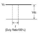
ゼロクロスポイントの検出に際しては、該当する固定子巻線へ電圧印加がされていない区間(図2Aおよび図2Bに示すU相では、スイッチング素子3a、3dの両方がオフとなる区間であるC1、C2、C3、C4)に、固定子巻線に現れる誘起電圧と、インバータ入力電圧Vdcの1/2との大小関係が反転するポイント(P1、P2)が検出される。
従って電気角1周期あたり、各相について2回、ゼロクロスポイントの位置信号が検出される。すなわち、3相全体としては、電気角60度毎に計6回、位置信号が検出される。
図2Aに示す、駆動信号U+、V+、およびW+による通電パターンにおいては、ゼロクロスポイント(P1)の位置検出後、電気角30度が経過する時点において、W+のオフと同時にU+がオンとなり、スイッチング素子3aがオンされる。これにより、電気角360度の全範囲において、常に3相のうちのいずれかの相の固定子巻線が通電される。
一方、図2Bに示す通電パターンにおいては、ゼロクロスポイント(P1)の位置検出後、電気角30度が経過する前に、W+がオフとなって、スイッチング素子3cがオフされたのち、電気角30度が経過する時点においてU+がオンとなって、スイッチング素子3aがオンされている。
C1~C4区間において固定子巻線に誘起電圧が現れるのは、他相のスイッチング素子がオンしている期間、すなわち、PWM制御によるスイッチング素子のオン期間のみである。従って、スイッチング素子のターンオフは、ターンオンより早く行われるように制御され、これにより、ブラシレスDCモータ4への電力供給区間が短くなるように制御される。これにより、PWM制御によるスイッチング素子のオンおよびオフの回数が少なくなるため、インバータ回路3の損失が抑制される。
また、固定子巻線の電力供給区間が短くなることで、PWM制御によるスイッチング素子のオン時間は長くなる。これにより、位置検出部5によるゼロクロスポイントの位置検出信号の取得が可能な期間が長くなる。従って、位置検出部5による位置検出の精度が向上する。
さらに、図2Aおよび図2Bに示すように、スイッチング素子のオフタイミングは、ゼロクロスポイント(P1)の位置検出の直後から、電気角30度が経過する時点まで(位置検出P1に対して区間A1の範囲)としている。これにより、ゼロクロスポイント(P1)の位置検出の結果に基づいて、確実に転流させることが可能となる。また、駆動波形が誘起電圧に対して進み位相となるため、遅れ位相によるトルク低下の発生が回避される。
このように、スイッチング素子3a~3fのオフタイミングを、ゼロクロスポイントの位置検出直後から電気角30度が経過する時点までとすることで、3相の固定子巻線の電力供給区間が90度以上、かつ、120度以下に調節される。また、電力供給の休止区間(A1、A2、A3)が短いほど大きな進角B(電力無供給区間の電気角の1/2)が自動的に付加されるようにしている。これにより、ブラシレスDCモータ4のトルクが増加して、ブラシレスDCモータ4に対して電力が供給されない、電力無供給区間がある状態であっても、ブラシレスDCモータ4の脱調等が回避され、安定したブラシレスDCモータ4の駆動が可能となる。
負荷が増加して、スイッチング素子のオフタイミングが、ゼロクロスポイントの位置検出後、電気角30度の経過時となったときの負荷が、120度での通電によって駆動可能な最大負荷である。この場合、オフタイミングを位置検出後、電気角30度の経過時に固定し、PWM制御のオン時間時比率を100%とした状態で、オンタイミングが最大で電気角30度まで進められる。すなわち、位置検出信号の取得と同時に転流される。これによって、各相の通電角を電気角150度にまで広げることができ、モータ駆動装置30によって駆動可能な負荷の領域を拡張することができる。このとき、ブラシレスDCモータ4の入力電流は、電気角120度での通電の場合と比較して、最大で17%程度増加する。
[5-2.速度制御の詳細]
次に、前述したスイッチング素子のオフタイミングの調整による、ブラシレスDCモータ4の速度制御について、フローチャートを用いて詳細に説明する。
次に、前述したスイッチング素子のオフタイミングの調整による、ブラシレスDCモータ4の速度制御について、フローチャートを用いて詳細に説明する。
図3は、スイッチング素子のオフタイミング調整制御の開始が判定されるフローチャートである。
まず、PWM制御部11で生成されたスイッチング素子のオン時間時比率が所定値より大きいか否か判定される(S11)。オン時間時比率が所定値より大きい場合(S11のYes)は、後述のオフタイミング調整制御が行われる(S12)。オン時間時比率が所定値以下の場合(S11のNo)は、PWM制御が行われる(S13)。
本実施の形態では、各スイッチング素子のオン区間の最小値は、電気角90度に設定されている。このため、オン時間時比率の所定値は、{(90度×2)-120度}/120度より、50%に設定されている。なお、オン時間時比率の所定値は、モータ駆動装置の用途を考慮して、適正な任意の値に設定される。
このように、本実施の形態では、スイッチング素子のオフタイミング調整制御が開始されるのは、所定のオン時間時比率以上の場合である。この際、オフタイミング調整制御とPWM制御とが併用される。これにより、ブラシレスDCモータ4の起動時等のように極端に駆動速度が低い場合若しくは低速駆動時で非常に負荷が低い場合、倍電圧入力時で比較的負荷が軽い場合若しくは低速の場合などにおいて、固定子巻線への電力供給区間が極端に短くなることによるブラシレスDCモータ4の起動の失敗、不安定な運転状態、または極端なトルク低下等が防止される。従って、あらゆる負荷条件においても、安定してブラシレスDCモータ4を駆動させることができる。
図4は、PWM制御からオフタイミング調整制御への移行が判定されるフローチャートである。
図3に示したフローにより、オフタイミング調整制御の開始が決定されると、スイッチング素子のオフタイミングが任意の時間だけ早められる(S21)。また、PWM制御による速度制御が行われる(S22)。なお、オフタイミングが早められる際は、前述のように、複数回に分けて、前回のオフタイミングより早められてもよい。
ここで、スイッチング素子のオフタイミングが早められているため(S21)、ブラシレスDCモータ4への電力供給区間が短くなる。従って、PWM制御によって、オン時間時比率は増加することになる。
PWM制御によるオン時間時比率が100%未満の場合(S23のYes)は、スイッチング素子のオフタイミングが早められる(S21)とともに、PWM制御が行われる(S22)。
オン時間時比率が100%に到達した場合(S23のNo)、オン時間時比率は100%の状態に保持される(S24)。すなわち、この場合は、PWM制御が行われない。また、スイッチング素子のオフタイミングの調整が行われる(S25)。つまり、オン時間時比率が100%となった時点で、PWM制御からオフタイミング調整制御に移行する。これにより、ブラシレスDCモータ4が目標速度で駆動するように、ブラシレスDCモータ4の駆動速度が制御される。
なお、スイッチング素子のオフタイミングが、ゼロクロスポイントの位置検出後、電気角30度(すなわち、120度での通電がされている状態)の経過時となった場合は、オンタイミング制御が行われてもよい。オンタイミング制御では、スイッチング素子のオンタイミングが最大で電気角30度まで進められる。これによって、ブラシレスDCモータ4の駆動可能な領域が拡張され、ブラシレスDCモータ4が目標速度で適切に駆動される。
次に、インバータ回路3への入力電圧が急激に上昇した場合の動作について、詳細に説明する。入力電圧の急激な上昇の要因としては、商用電源に瞬時停電が生じてインバータ回路3の入力電圧が低下した状態において、停電から復帰した場合、および、コンバータ回路2における整流方式が全波整流から倍電圧整流に切り替わった瞬間などが想定される。
図5は、インバータ回路3の入力電圧の上昇時の動作を示すフローチャートである。
まず、入力電圧検出部15によって、インバータ回路3の入力電圧が検出される(S31)。
次に、インバータ回路3の入力電圧が前回の検出値より規定値以上上昇したか否か判定される(S32)。規定値以上の上昇がない場合(S32のNo)は、今回の入力電圧の検出値を前回値として格納し(S35)、フローが終了する。
一方、電圧の上昇が規定値以上であると判定された場合(S32のYes)は、検出された入力電圧に応じたPWM制御のオン時間時比率が計算される(S33)。本実施の形態においては、オン時間時比率は、電圧の変動が生じる前後でブラシレスDCモータ4の印加電圧が等しくなるように、計算される。具体的には、「オン時間時比率[%]=(前回の検出電圧[V]/今回の検出電圧[V])×100」として算出される。
PWM制御部11は、算出されたオン時間時比率でのPWM波形を出力する(S34)。また、今回のインバータ回路3の入力電圧の検出値が、前回値として格納される(S35)。
このようにインバータ回路3の入力電圧が急激に上昇した場合、インバータ回路3の入力電圧の変化前後でブラシレスDCモータ4への入力電圧が同等となるようなPWM制御のオン時間時比率が瞬時に計算され、出力される。これにより、ブラシレスDCモータ4への入力電圧の急激な変化が抑制され、ブラシレスDCモータ4の脱調が回避される。また、回転子の永久磁石の減磁の原因となる過電流の発生が防止される。
また、インバータ回路3への入力電圧が全波整流から倍電圧整流に切り替えられて、ブラシレスDCモータ4の出力範囲が拡張される際においても、ブラシレスDCモータ4を一旦停止させることなく切り替えることができる。従って、非常に使い勝手の良いモータ駆動装置を提供することができる。
なお、インバータ回路3の入力電圧の検出周期は、電圧変動に対する応答性を良くするために、PWMタイマ周期とすることが好ましい。しかし、使用されるプロセッサの計算能力およびA/D変換速度などを考慮して設定される。
次に、スイッチング素子のオフタイミング調整制御への移行後の、ブラシレスDCモータ4の速度制御について、図1および図6を用いて説明する。
図6は、オフタイミング調整制御を示すフローチャートである。
速度検出部6で検出されたブラシレスDCモータ4の駆動速度と目標速度との偏差が、速度誤差検出部7によって検出される。
図6において、ブラシレスDCモータ4の駆動速度が目標速度より早い場合(S41のYes)は、オフタイミング制御部10がスイッチング素子のオフタイミングを早めることが可能か否か判定される(S42)。このとき、PWM制御部11でのオン時間時比率は100%に保持されている。オフタイミングを早めることが可能である場合(S42のYes)には、スイッチング素子のオフタイミングが早められる(S43)。これによって、固定子巻線への電力供給区間を減少させて、ブラシレスDCモータ4の駆動速度が低下するように速度制御が行われる。オフタイミングを早めることが不可能である場合(S42のNo)は、PWM制御部11によるPWM制御が行われる(S44)。
なお、本実施の形態において、スイッチング素子のオフタイミングを早めることが可能か否かの判定は、以下のように行われる。
スイッチング素子のオフタイミングがゼロクロスポイントの位置検出の直後である場合は、これ以上オフタイミングを早めることができないと判定される。
本実施の形態では、進角を0度としているため、各固定子巻線へ電力供給区間の最小値は、電気角90度である。
ブラシレスDCモータ4の駆動速度が目標速度より遅いと判定された場合(S45のYes)は、スイッチング素子のオフタイミングが、ゼロクロスポイントの位置検出直後から、電気角30度の経過時までの間であるか否か判定される(S46)。
スイッチング素子のオフタイミングが電気角30度の経過時より前である場合(S46のYes)は、スイッチング素子のオフタイミングが遅らせられる(S47)。これにより、ブラシレスDCモータ4の固定子巻線への電力供給区間が増加され、ブラシレスDCモータ4の駆動速度が増加するように、速度制御が行われる。
一方、オフスイッチング素子のオフタイミングが電気角30度の経過時以降である場合(S46のNo)は、これ以上スイッチング素子のオフタイミングを遅らせると、誘起電圧に対して印加電圧位相が遅れ位相となり、モータトルクの低下およびこれに伴う脱調等が生じる可能性がある。このため、スイッチング素子のオンタイミングが早められる(S48)。これにより、固定子巻線への電力供給区間が増加され、ブラシレスDCモータ4の駆動速度が増加するように、速度制御が行われる。
本実施の形態では、スイッチング素子のオンタイミングが早められる範囲の上限は、ゼロクロスポイントの位置検出の直後までとしている。スイッチング素子のオフタイミングが、ゼロクロスポイントの位置検出の直後のときの固定子巻線への電力供給区間の最大値は、電気角150度となる。このとき、ブラシレスDCモータ4に流れる電流は、電気角120度の場合の電流に対して、約17%増加する。従って、ブラシレスDCモータ4の出力範囲も拡張される。
なお、ブラシレスDCモータ4の駆動速度が目標速度と等しい場合(S45のNo)は、フローが終了する。
また、本実施の形態では、前述の通り、進角を0度としている。このため、通電角が電気角120度の場合、スイッチング素子のオフタイミングとオンタイミングとが、ゼロクロスポイントの位置検出後、電気角30度の経過時で一致する。
ここで、モータ駆動装置30は、IPMモータ(Interior Permanent Magnet Motor)を含め、種々のモータを最適に駆動可能であることが望ましい。例えば、IPMモータの固定子の内部には、永久磁石が埋め込まれている。このため、IPMモータの最適な駆動の実現のためには、適切な進角を設ける必要がある。
本実施の形態では、スイッチング素子のオフタイミング調整の範囲およびオンタイミング調整の範囲は、以下のように設定されている。
すなわち、スイッチング素子のオフタイミングは、ゼロクロスポイントの位置検出の直後から、「(電気角30度)-(進角)」の経過時までの範囲である。
また、スイッチング素子のオンタイミングは、ゼロクロスポイントの位置検出後、「(電気角30度)-(進角)」の経過時である。
従って、例えば、進角が10度の場合、スイッチング素子のオフタイミングは、ゼロクロスポイントの位置検出直後から、電気角20度の経過時までの範囲において調整され、オンタイミングは、ゼロクロスポイントの位置検出後、電気角20度の経過時に調整される。また、ゼロクロスポイントの位置検出時からオフタイミングまでの電気角、および、ゼロクロスポイントの位置検出時からオンタイミングまでの電気角の和は、60度以下となるようにしている。さらに、オフタイミングは、オンタイミングから、電気角0度から30度の経過時までの間の任意の範囲で調整される。これにより、進角、オンタイミング、およびオフタイミングは、ゼロクロスポイントの位置検出直後から、電気角30度の経過時までの範囲において、自由に設定することができる。
なお、進角が付加されたときの各スイッチング素子のオン区間(通電角)は、「(電気角90度)+(進角)」から電気角120度の範囲で調整される。
なお、ブラシレスDCモータ4が、高速かつ高負荷で駆動される場合は、スイッチング素子のオンタイミングおよびオフタイミングは、以下のように調整されてもよい。
すなわち、スイッチング素子のオフタイミングは、ゼロクロスポイントの位置検出後、「(電気角30度)-(進角)」の経過時に調整される。また、スイッチング素子のオンタイミングは、ゼロクロスポイントの位置検出直後から「電気角30度-進角」の経過時までの範囲で調整される。これによって、各スイッチング素子のオン区間は、電気角120度から「(電気角150)-(進角)」の範囲内で調整することができる。
以上により、スイッチング素子のオンタイミングおよびオフタイミングを調整することにより、電気角90度から150度までの範囲(進角0度の場合)でブラシレスDCモータへの電力供給区間の調整が行われる。従って、本実施の形態のモータ駆動装置30は、低速かつ低負荷の状態から、高速かつ高負荷の状態までの、幅広い範囲においてブラシレスDCモータ4を駆動することが可能である。
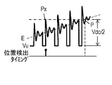
次に、本実施の形態におけるブラシレスDCモータの端子電圧について、図7A~図7Dを用いて説明する。
図7Aおよび図7Bは、それぞれ、図2Aにおける区間C1および区間F1の端子電圧を示している。図7Cおよび図7Dは、それぞれ、図2Bにおける区間C3および区間F2の端子電圧を示している。
図7Aおよび図7Bに示すように、図2Aに示された、PWM制御された場合の波形には、高周波のPWMキャリア周波数成分(周期f)が重畳されている。
また図7Aに示すように、区間C1では、PWM制御がオンとなった瞬間に、固定子巻線または浮遊容量等の影響によるリンギングノイズ成分も重畳される。
区間C1においては、ブラシレスDCモータ4の端子電圧Vuと、インバータ入力電圧Vdcの1/2とが比較され、その大小関係が反転するポイントがブラシレスDCモータ4の誘起電圧のゼロクロスポイント(P点)として検出される。
しかし、図7Aに示すように、端子電圧Vuにはリンギングノイズ成分が重畳されているため、Px点がゼロクロスポイントであると誤検出される。このように誤った位置検出がされると、ブラシレスDCモータ4の駆動速度の脈動、機器の振動および騒音の増大、および駆動効率の低下などが引き起こされる。
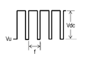
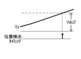
一方、図7Cに示すように、PWM制御のオン時間時比率が100%の場合、端子電圧Vuには誘起電圧波形が現れる。このため、ゼロクロスポイント(P点)の位置を正確に検出することが可能である。従って、低騒音、低振動、かつ低損失な、安定したブラシレスDCモータ4の駆動を実現することができる。
また、図7Bに示すように、区間F1では、PWM制御による高周波でのスイッチング素子のオンおよびオフに伴うスイッチング損失が発生する。一方、図7Dに示すように、オン時間時比率が100%で駆動される場合は、スイッチング素子のスイッチング動作が行われないため、スイッチング損失は発生しない。従って、モータ駆動装置30の回路損失が低減され、モータ駆動装置30の高効率化を実現することができる。
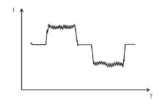
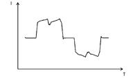
図8Aは、PWM制御された場合のブラシレスDCモータの相電流波形を示す図である。図8Bは、オン時間時比率が100%の場合のブラシレスDCモータの相電流波形を示す図である。
図8Aは、電気角120度での通電の場合の波形を示している。図8Aに示すように、PWM制御された場合の相電流波形には、PWM制御によるスイッチング素子のオンおよびオフに伴う高周波電流成分が重畳されている。この高周波電流成分は、モータ鉄損の原因となる。
一方、図8Bに示すように、PWM制御のオン時間時比率が100%の状態でブラシレスDCモータ4が駆動されている場合には、高周波電流成分は発生しない。このため、モータ駆動装置30のモータ損失が低減され、モータ駆動装置の高効率化を実現することができる。
[6.モータ駆動装置を用いた冷蔵庫]
以上のように構成されたモータ駆動装置30により駆動される圧縮機17を用いた冷凍サイクル装置について説明する。ここでは、冷凍サイクル装置の一例として、冷蔵庫について説明する。
以上のように構成されたモータ駆動装置30により駆動される圧縮機17を用いた冷凍サイクル装置について説明する。ここでは、冷凍サイクル装置の一例として、冷蔵庫について説明する。
近年は、冷蔵庫に真空断熱材が採用されるなどして、冷蔵庫の断熱性能が向上しており、冷蔵庫の外部からの熱の侵入が非常に少ない。このため、家事が行われるのに伴って扉の開閉が頻繁に行われる朝夕の時間帯を除くと、1日の大半の時間帯において、冷蔵庫内は安定した冷却状態にある。このとき、圧縮機17は、冷凍能力の低い、低速かつ低負荷の状態で駆動されている。従って、冷蔵庫の消費電力を削減するためには、圧縮機17に含まれるブラシレスDCモータ4が、低速かつ低負荷で駆動されている際の効率を上げることが、非常に有効である。
本実施の形態では、ブラシレスDCモータ4が低速かつ低負荷で駆動されている状態において、PWM制御による、高周波でのスイッチング素子のオンおよびオフのスイッチング動作が行われない。その代わりに、ブラシレスDCモータ4は、PWM制御のオン時間時比率が100%となるように、スイッチング素子のオンタイミングまたはオフタイミングが調整されて、駆動速度が制御される。これにより、PWM制御によるインバータ回路3のスイッチング損失の発生が回避され、インバータ回路3の回路効率が大幅に向上する。
本実施の形態では、インバータ回路3のスイッチング素子としてMOSFETが用いられている。MOSFETは、オン時の出力電流の経路中にPN接合を有さない。このため、特にMOSFETの低電流出力時におけるオン時の損失は、IGBT等の他のパワーデバイスのそれと比較して非常に低い。
上述のように、冷蔵庫は1日の大半の時間帯において、低速かつ低負荷の状態で駆動されており、ブラシレスDCモータ4に流れる電流が小さい。従って、本開示のモータ駆動装置30が、上述のように冷蔵庫の圧縮機17に用いられる場合、インバータ回路3のスイッチング素子としてMOSFETが用いられることで、冷蔵庫の消費電力が効果的に削減される。
また、PWM制御のオン時間比率を100%に設定して、PWM制御によるオンおよびオフのスイッチング動作が行われないようにすることで、ブラシレスDCモータ4の固定子巻線に流れる相電流に高周波電流成分が重畳されることを回避することができる。これにより、モータ鉄損が大幅に低減され、モータ効率の向上を図ることができる。
また、PWM制御では、一般的に1kHから20kHz程度のPWM周波数でスイッチング素子のスイッチング動作が行われ、このスイッチング動作の周波数成分に起因した騒音が発生する。冷蔵庫は、昼夜にかかわらず1日中運転されるため、冷蔵庫の静音性能を向上させることは非常に重要である。本実施の形態のモータ駆動装置30は、オン時間時比率が100%に設定されるため、PWM制御に起因した騒音の発生が回避され、よって、冷蔵庫の静音性能を向上させることができる。
また、冷蔵庫は圧縮機17が一旦停止した場合、圧縮機17の機械部の信頼性を確保するため、低圧側と高圧側の圧力差が平衡するまで再起動を遅延させる必要がある。本実施の形態のモータ駆動装置30は、インバータ回路3の入力電圧が急上昇したときも、ブラシレスDCモータ4の入力電圧の変動を抑制し、安定したブラシレスDCモータ4の駆動を継続できる。従って、圧縮機17の停止による冷蔵庫内の温度の上昇がなく、安定した冷却状態を保つことができる。
また、冷蔵庫の負荷増大に伴って、圧縮機17を高速駆動させて冷凍能力を上げた運転を行う場合も、圧縮機17の停止による冷蔵庫内の冷却のロスを回避しつつ、ブラシレスDCモータの入力電圧を倍電圧へ切り替えることができる。
以上のように、本開示にかかるモータ駆動装置は、回路損失を低減してブラシレスDCモータの効率の向上を図るとともに、信頼性の向上を図ることができる。また、ブラシレスDCモータの駆動騒音および機器の振動の低減が可能となる。このため、冷蔵庫、エアコン、洗濯機、ポンプ、扇風機、ファン、および電気掃除機など、ブラシレスDCモータが用いられる、あらゆる機器に適用することが可能である。
1 交流電源
2 コンバータ回路
2a 整流回路
2b 平滑回路
2c スイッチ(切替部)
3 インバータ回路
3a,3b,3c,3d,3e,3f スイッチング素子
4 ブラシレスDCモータ
5 位置検出部
6 速度検出部
7 速度誤差検出部
8 通電相制御部
11 PWM制御部
16 圧縮要素
17 圧縮機
18 凝縮器
19 減圧器
20 蒸発器
21 冷蔵庫
22 断熱壁
23 食品貯蔵室
30 モータ駆動装置
2 コンバータ回路
2a 整流回路
2b 平滑回路
2c スイッチ(切替部)
3 インバータ回路
3a,3b,3c,3d,3e,3f スイッチング素子
4 ブラシレスDCモータ
5 位置検出部
6 速度検出部
7 速度誤差検出部
8 通電相制御部
11 PWM制御部
16 圧縮要素
17 圧縮機
18 凝縮器
19 減圧器
20 蒸発器
21 冷蔵庫
22 断熱壁
23 食品貯蔵室
30 モータ駆動装置
Claims (5)
- 回転子を有するブラシレスDCモータと、
6個のスイッチング素子を含んで構成され、前記ブラシレスDCモータに電力を供給するインバータ回路と、
前記回転子の位置を検出する位置検出部と、
前記スイッチング素子を高周波数でオンおよびオフすることで、前記ブラシレスDCモータに印加される電圧を調整するPWM制御部と、を有するモータ駆動装置であって、
前記モータ駆動装置はさらに、
前記PWM制御による前記スイッチング素子のオン時間時比率が最大となるようしつつ、前記ブラシレスDCモータの各相の通電状態を設定する通電相制御部と、
前記インバータ回路の入力電圧を検出する入力電圧検出部と、を有し、
前記PWM制御部は、前記インバータ回路の前記入力電圧の変化に応じて、前記PWM制御のオン時間時比率を設定する、
モータ駆動装置。 - 前記PWM制御部は、前記インバータ回路の前記入力電圧の前記変化の前後で、前記ブラシレスDCモータへ印加される前記電圧が変化しないように、前記スイッチング素子のオン時間時比率を設定する、
請求項1に記載のモータ駆動装置。 - 前記モータ駆動装置はさらに、
交流電圧を直流電圧に変換する整流回路と、
前記整流回路の出力を直流電圧にする平滑回路と、
前記整流回路を全波整流および倍電圧整流の間で切り替える切替部と、を有し、
前記切替部により前記全波整流から前記倍電圧整流に切り替えられると、前記PWM制御部は前記スイッチング素子のオン時間時比率を下げる、
請求項1または請求項2に記載のモータ駆動装置。 - 前記ブラシレスDCモータは、冷凍サイクル中に設けられた圧縮機を駆動する、
請求項1から請求項3のいずれか一つに記載のモータ駆動装置。 - 請求項4に記載のモータ駆動装置を有する冷蔵庫。
Priority Applications (1)
| Application Number | Priority Date | Filing Date | Title |
|---|---|---|---|
| CN201880051912.8A CN111034026A (zh) | 2017-10-27 | 2018-10-16 | 电动机驱动装置和使用它的冷藏库 |
Applications Claiming Priority (2)
| Application Number | Priority Date | Filing Date | Title |
|---|---|---|---|
| JP2017-208351 | 2017-10-27 | ||
| JP2017208351A JP6970871B2 (ja) | 2017-10-27 | 2017-10-27 | モータ駆動装置および、これを用いた冷蔵庫 |
Publications (1)
| Publication Number | Publication Date |
|---|---|
| WO2019082718A1 true WO2019082718A1 (ja) | 2019-05-02 |
Family
ID=66246448
Family Applications (1)
| Application Number | Title | Priority Date | Filing Date |
|---|---|---|---|
| PCT/JP2018/038387 WO2019082718A1 (ja) | 2017-10-27 | 2018-10-16 | モータ駆動装置および、これを用いた冷蔵庫 |
Country Status (3)
| Country | Link |
|---|---|
| JP (1) | JP6970871B2 (ja) |
| CN (1) | CN111034026A (ja) |
| WO (1) | WO2019082718A1 (ja) |
Citations (5)
| Publication number | Priority date | Publication date | Assignee | Title |
|---|---|---|---|---|
| JP2006050804A (ja) * | 2004-08-05 | 2006-02-16 | Matsushita Electric Ind Co Ltd | 冷蔵庫の制御装置 |
| JP2009261212A (ja) * | 2008-03-17 | 2009-11-05 | Toshiba Corp | インバータ装置およびインバータシステム |
| JP2010057216A (ja) * | 2008-08-26 | 2010-03-11 | Toshiba Corp | インバータ装置 |
| US20120074917A1 (en) * | 2010-04-02 | 2012-03-29 | Hsing-Kuo Chao | Adaptive slope-compensation module and method thereof |
| CN106828181A (zh) * | 2017-04-13 | 2017-06-13 | 安费诺汽车连接系统(常州)有限公司 | 电动汽车充电控制装置 |
Family Cites Families (2)
| Publication number | Priority date | Publication date | Assignee | Title |
|---|---|---|---|---|
| JPH06165519A (ja) * | 1992-11-27 | 1994-06-10 | Sanyo Electric Co Ltd | 電動機の駆動方法 |
| JP6533950B2 (ja) * | 2015-08-28 | 2019-06-26 | パナソニックIpマネジメント株式会社 | モータ駆動装置、およびこれを用いた圧縮機の駆動装置、冷凍装置および冷蔵庫 |
-
2017
- 2017-10-27 JP JP2017208351A patent/JP6970871B2/ja active Active
-
2018
- 2018-10-16 CN CN201880051912.8A patent/CN111034026A/zh active Pending
- 2018-10-16 WO PCT/JP2018/038387 patent/WO2019082718A1/ja active Application Filing
Patent Citations (5)
| Publication number | Priority date | Publication date | Assignee | Title |
|---|---|---|---|---|
| JP2006050804A (ja) * | 2004-08-05 | 2006-02-16 | Matsushita Electric Ind Co Ltd | 冷蔵庫の制御装置 |
| JP2009261212A (ja) * | 2008-03-17 | 2009-11-05 | Toshiba Corp | インバータ装置およびインバータシステム |
| JP2010057216A (ja) * | 2008-08-26 | 2010-03-11 | Toshiba Corp | インバータ装置 |
| US20120074917A1 (en) * | 2010-04-02 | 2012-03-29 | Hsing-Kuo Chao | Adaptive slope-compensation module and method thereof |
| CN106828181A (zh) * | 2017-04-13 | 2017-06-13 | 安费诺汽车连接系统(常州)有限公司 | 电动汽车充电控制装置 |
Also Published As
| Publication number | Publication date |
|---|---|
| CN111034026A (zh) | 2020-04-17 |
| JP6970871B2 (ja) | 2021-11-24 |
| JP2019083595A (ja) | 2019-05-30 |
Similar Documents
| Publication | Publication Date | Title |
|---|---|---|
| KR101804713B1 (ko) | 직류 전원 장치, 전동기 구동 장치, 공기 조화기 및 냉장고 | |
| JP5195444B2 (ja) | ブラシレスdcモータの駆動装置並びにこれを用いた冷蔵庫及び空気調和機 | |
| EP2388906B1 (en) | Motor driving device and electric equipment using same | |
| KR101850226B1 (ko) | 직류 전원 장치, 전동기 구동 장치, 공기 조화기 및 냉장고 | |
| KR100799009B1 (ko) | 브러시리스 dc 모터의 구동 방법 및 그 장치 | |
| CN109155601B (zh) | 电机驱动装置和具有使用该电机驱动装置的压缩机的电设备 | |
| WO2004084401A1 (ja) | 電動圧縮機 | |
| CN105027419A (zh) | 电动机驱动装置和使用其的电设备 | |
| JP2017046513A (ja) | モータ駆動装置、およびこれを用いた圧縮機の駆動装置、冷凍装置および冷蔵庫 | |
| JP5375260B2 (ja) | モータ駆動装置およびこれを用いた冷蔵庫 | |
| JP2008289310A (ja) | モータ駆動装置およびこれを用いた冷蔵庫 | |
| JP2012222842A (ja) | モータ駆動装置およびにこれを用いた電気機器 | |
| JP3672637B2 (ja) | 圧縮機電動機制御装置 | |
| JP2010252406A (ja) | モータ駆動装置およびこれを用いた冷蔵庫 | |
| JP5521405B2 (ja) | モータ駆動装置およびこれを用いた電気機器 | |
| CN111034011B (zh) | 电动机驱动装置和使用它的冷藏库 | |
| JP2002112588A (ja) | 冷凍システムの制御装置 | |
| JP2010252480A (ja) | モータ駆動装置およびこれを用いた冷蔵庫 | |
| WO2019082718A1 (ja) | モータ駆動装置および、これを用いた冷蔵庫 | |
| JP6706757B2 (ja) | モータ駆動装置および、これを用いた圧縮機を有する電気機器 | |
| JP5747145B2 (ja) | モータ駆動装置およびこれを用いた電気機器 | |
| JP2001309692A (ja) | 冷凍システムの制御装置 | |
| JP6450939B2 (ja) | モータ駆動装置、およびこれを用いた圧縮機の駆動装置、冷凍装置および冷蔵庫 | |
| JP6706756B2 (ja) | モータ駆動装置および、これを用いた圧縮機を有する電気機器 | |
| JP2004324552A (ja) | 電動圧縮機 |
Legal Events
| Date | Code | Title | Description |
|---|---|---|---|
| 121 | Ep: the epo has been informed by wipo that ep was designated in this application |
Ref document number: 18870965 Country of ref document: EP Kind code of ref document: A1 |
|
| NENP | Non-entry into the national phase |
Ref country code: DE |
|
| 122 | Ep: pct application non-entry in european phase |
Ref document number: 18870965 Country of ref document: EP Kind code of ref document: A1 |