WO2019082504A1 - 情報処理装置、情報処理方法、プログラム、及びモニタリングシステム - Google Patents
情報処理装置、情報処理方法、プログラム、及びモニタリングシステムInfo
- Publication number
- WO2019082504A1 WO2019082504A1 PCT/JP2018/031949 JP2018031949W WO2019082504A1 WO 2019082504 A1 WO2019082504 A1 WO 2019082504A1 JP 2018031949 W JP2018031949 W JP 2018031949W WO 2019082504 A1 WO2019082504 A1 WO 2019082504A1
- Authority
- WO
- WIPO (PCT)
- Prior art keywords
- information processing
- information
- processing apparatus
- snow
- measurement data
- Prior art date
- Legal status (The legal status is an assumption and is not a legal conclusion. Google has not performed a legal analysis and makes no representation as to the accuracy of the status listed.)
- Ceased
Links
Images


Classifications
-
- G—PHYSICS
- G01—MEASURING; TESTING
- G01N—INVESTIGATING OR ANALYSING MATERIALS BY DETERMINING THEIR CHEMICAL OR PHYSICAL PROPERTIES
- G01N21/00—Investigating or analysing materials by the use of optical means, i.e. using sub-millimetre waves, infrared, visible or ultraviolet light
- G01N21/17—Systems in which incident light is modified in accordance with the properties of the material investigated
- G01N21/47—Scattering, i.e. diffuse reflection
-
- B—PERFORMING OPERATIONS; TRANSPORTING
- B60—VEHICLES IN GENERAL
- B60T—VEHICLE BRAKE CONTROL SYSTEMS OR PARTS THEREOF; BRAKE CONTROL SYSTEMS OR PARTS THEREOF, IN GENERAL; ARRANGEMENT OF BRAKING ELEMENTS ON VEHICLES IN GENERAL; PORTABLE DEVICES FOR PREVENTING UNWANTED MOVEMENT OF VEHICLES; VEHICLE MODIFICATIONS TO FACILITATE COOLING OF BRAKES
- B60T8/00—Arrangements for adjusting wheel-braking force to meet varying vehicular or ground-surface conditions, e.g. limiting or varying distribution of braking force
- B60T8/17—Using electrical or electronic regulation means to control braking
- B60T8/171—Detecting parameters used in the regulation; Measuring values used in the regulation
-
- B—PERFORMING OPERATIONS; TRANSPORTING
- B60—VEHICLES IN GENERAL
- B60T—VEHICLE BRAKE CONTROL SYSTEMS OR PARTS THEREOF; BRAKE CONTROL SYSTEMS OR PARTS THEREOF, IN GENERAL; ARRANGEMENT OF BRAKING ELEMENTS ON VEHICLES IN GENERAL; PORTABLE DEVICES FOR PREVENTING UNWANTED MOVEMENT OF VEHICLES; VEHICLE MODIFICATIONS TO FACILITATE COOLING OF BRAKES
- B60T8/00—Arrangements for adjusting wheel-braking force to meet varying vehicular or ground-surface conditions, e.g. limiting or varying distribution of braking force
- B60T8/17—Using electrical or electronic regulation means to control braking
- B60T8/172—Determining control parameters used in the regulation, e.g. by calculations involving measured or detected parameters
-
- B—PERFORMING OPERATIONS; TRANSPORTING
- B60—VEHICLES IN GENERAL
- B60W—CONJOINT CONTROL OF VEHICLE SUB-UNITS OF DIFFERENT TYPE OR DIFFERENT FUNCTION; CONTROL SYSTEMS SPECIALLY ADAPTED FOR HYBRID VEHICLES; ROAD VEHICLE DRIVE CONTROL SYSTEMS FOR PURPOSES NOT RELATED TO THE CONTROL OF A PARTICULAR SUB-UNIT
- B60W40/00—Estimation or calculation of non-directly measurable driving parameters for road vehicle drive control systems not related to the control of a particular sub unit, e.g. by using mathematical models
- B60W40/02—Estimation or calculation of non-directly measurable driving parameters for road vehicle drive control systems not related to the control of a particular sub unit, e.g. by using mathematical models related to ambient conditions
- B60W40/06—Road conditions
-
- G—PHYSICS
- G01—MEASURING; TESTING
- G01B—MEASURING LENGTH, THICKNESS OR SIMILAR LINEAR DIMENSIONS; MEASURING ANGLES; MEASURING AREAS; MEASURING IRREGULARITIES OF SURFACES OR CONTOURS
- G01B11/00—Measuring arrangements characterised by the use of optical techniques
- G01B11/02—Measuring arrangements characterised by the use of optical techniques for measuring length, width or thickness
- G01B11/06—Measuring arrangements characterised by the use of optical techniques for measuring length, width or thickness for measuring thickness ; e.g. of sheet material
- G01B11/0616—Measuring arrangements characterised by the use of optical techniques for measuring length, width or thickness for measuring thickness ; e.g. of sheet material of coating
- G01B11/0625—Measuring arrangements characterised by the use of optical techniques for measuring length, width or thickness for measuring thickness ; e.g. of sheet material of coating with measurement of absorption or reflection
- G01B11/0633—Measuring arrangements characterised by the use of optical techniques for measuring length, width or thickness for measuring thickness ; e.g. of sheet material of coating with measurement of absorption or reflection using one or more discrete wavelengths
-
- G—PHYSICS
- G01—MEASURING; TESTING
- G01B—MEASURING LENGTH, THICKNESS OR SIMILAR LINEAR DIMENSIONS; MEASURING ANGLES; MEASURING AREAS; MEASURING IRREGULARITIES OF SURFACES OR CONTOURS
- G01B11/00—Measuring arrangements characterised by the use of optical techniques
- G01B11/02—Measuring arrangements characterised by the use of optical techniques for measuring length, width or thickness
- G01B11/06—Measuring arrangements characterised by the use of optical techniques for measuring length, width or thickness for measuring thickness ; e.g. of sheet material
- G01B11/0616—Measuring arrangements characterised by the use of optical techniques for measuring length, width or thickness for measuring thickness ; e.g. of sheet material of coating
- G01B11/0641—Measuring arrangements characterised by the use of optical techniques for measuring length, width or thickness for measuring thickness ; e.g. of sheet material of coating with measurement of polarization
- G01B11/065—Measuring arrangements characterised by the use of optical techniques for measuring length, width or thickness for measuring thickness ; e.g. of sheet material of coating with measurement of polarization using one or more discrete wavelengths
-
- G—PHYSICS
- G01—MEASURING; TESTING
- G01N—INVESTIGATING OR ANALYSING MATERIALS BY DETERMINING THEIR CHEMICAL OR PHYSICAL PROPERTIES
- G01N21/00—Investigating or analysing materials by the use of optical means, i.e. using sub-millimetre waves, infrared, visible or ultraviolet light
- G01N21/17—Systems in which incident light is modified in accordance with the properties of the material investigated
- G01N21/21—Polarisation-affecting properties
-
- G—PHYSICS
- G01—MEASURING; TESTING
- G01N—INVESTIGATING OR ANALYSING MATERIALS BY DETERMINING THEIR CHEMICAL OR PHYSICAL PROPERTIES
- G01N21/00—Investigating or analysing materials by the use of optical means, i.e. using sub-millimetre waves, infrared, visible or ultraviolet light
- G01N21/17—Systems in which incident light is modified in accordance with the properties of the material investigated
- G01N21/25—Colour; Spectral properties, i.e. comparison of effect of material on the light at two or more different wavelengths or wavelength bands
- G01N21/31—Investigating relative effect of material at wavelengths characteristic of specific elements or molecules, e.g. atomic absorption spectrometry
- G01N21/35—Investigating relative effect of material at wavelengths characteristic of specific elements or molecules, e.g. atomic absorption spectrometry using infrared light
- G01N21/3554—Investigating relative effect of material at wavelengths characteristic of specific elements or molecules, e.g. atomic absorption spectrometry using infrared light for determining moisture content
-
- G—PHYSICS
- G01—MEASURING; TESTING
- G01N—INVESTIGATING OR ANALYSING MATERIALS BY DETERMINING THEIR CHEMICAL OR PHYSICAL PROPERTIES
- G01N21/00—Investigating or analysing materials by the use of optical means, i.e. using sub-millimetre waves, infrared, visible or ultraviolet light
- G01N21/84—Systems specially adapted for particular applications
- G01N21/88—Investigating the presence of flaws or contamination
- G01N21/94—Investigating contamination, e.g. dust
-
- G—PHYSICS
- G01—MEASURING; TESTING
- G01W—METEOROLOGY
- G01W1/00—Meteorology
-
- G—PHYSICS
- G01—MEASURING; TESTING
- G01W—METEOROLOGY
- G01W1/00—Meteorology
- G01W1/14—Rainfall or precipitation gauges
-
- G—PHYSICS
- G08—SIGNALLING
- G08B—SIGNALLING SYSTEMS, e.g. PERSONAL CALLING SYSTEMS; ORDER TELEGRAPHS; ALARM SYSTEMS
- G08B19/00—Alarms responsive to two or more different undesired or abnormal conditions, e.g. burglary and fire, abnormal temperature and abnormal rate of flow
- G08B19/02—Alarm responsive to formation or anticipated formation of ice
-
- G—PHYSICS
- G01—MEASURING; TESTING
- G01N—INVESTIGATING OR ANALYSING MATERIALS BY DETERMINING THEIR CHEMICAL OR PHYSICAL PROPERTIES
- G01N21/00—Investigating or analysing materials by the use of optical means, i.e. using sub-millimetre waves, infrared, visible or ultraviolet light
- G01N21/84—Systems specially adapted for particular applications
- G01N21/88—Investigating the presence of flaws or contamination
- G01N21/94—Investigating contamination, e.g. dust
- G01N2021/945—Liquid or solid deposits of macroscopic size on surfaces, e.g. drops, films, or clustered contaminants
-
- G—PHYSICS
- G01—MEASURING; TESTING
- G01N—INVESTIGATING OR ANALYSING MATERIALS BY DETERMINING THEIR CHEMICAL OR PHYSICAL PROPERTIES
- G01N21/00—Investigating or analysing materials by the use of optical means, i.e. using sub-millimetre waves, infrared, visible or ultraviolet light
- G01N21/17—Systems in which incident light is modified in accordance with the properties of the material investigated
- G01N21/47—Scattering, i.e. diffuse reflection
- G01N21/4738—Diffuse reflection, e.g. also for testing fluids, fibrous materials
- G01N21/474—Details of optical heads therefor, e.g. using optical fibres
-
- G—PHYSICS
- G01—MEASURING; TESTING
- G01N—INVESTIGATING OR ANALYSING MATERIALS BY DETERMINING THEIR CHEMICAL OR PHYSICAL PROPERTIES
- G01N21/00—Investigating or analysing materials by the use of optical means, i.e. using sub-millimetre waves, infrared, visible or ultraviolet light
- G01N21/84—Systems specially adapted for particular applications
- G01N21/8422—Investigating thin films, e.g. matrix isolation method
Definitions
- the present invention relates to an information processing apparatus, an information processing method, a program, and a monitoring system that can be applied to monitoring of the state of the surface of a road surface or a structure.
- the road surface It is important in terms of safety management to monitor the icing and icing conditions of the road surface and the runway surface (hereinafter referred to as "the road surface").
- the road surface For the monitoring, there is known a technique of measuring the depth of snow by measuring the distance by irradiating a laser, a sound wave or the like from the outside on the road surface. There is also known a technique of measuring the state of snowfall or the like by irradiating an electromagnetic wave from the outside.
- Patent Document 1 it is possible to embed in the road surface or the inside of a structure, and determine the presence or absence of snow etc. (snow, ice, water, volcanic ash, sand, etc.) locally attached to the road surface or the surface of the structure.
- snow etc. snow, ice, water, volcanic ash, sand, etc.
- a snow and ice monitoring device capable of monitoring detailed snow depth and quality conditions is disclosed.
- an object of the present invention is to provide an information processing apparatus and an information processing method capable of monitoring a state of a surface to be measured with high accuracy and effectively using the monitoring result. It is about providing a program and a monitoring system.
- an information processing apparatus includes an acquisition unit and a generation unit.
- the acquisition unit acquires measurement data on a surface to be measured.
- the generation unit generates deposit information on deposits deposited on the surface to be measured based on features of the acquired measurement data.
- deposit information is generated based on the features of the measurement data of the surface to be measured. This makes it possible to monitor the state of the surface to be measured with high accuracy and to effectively use the monitoring result.
- the deposit information includes at least the type, thickness, density, particle size, moisture content, temperature, deposition distribution, coefficient of friction, information indicative of slipperiness, and evaluation value according to a predetermined standard. It may include one. This enables high-precision monitoring and effective use of the monitoring results.
- the evaluation value according to the predetermined standard may include a runway status code defined by the International Civil Aviation Organization. As a result, management of the runway based on the runway status code is easily realized.
- the generation unit may generate prediction information for predicting the state of the surface to be measured based on at least one of the acquired measurement data and the generated deposit information. This enables high-precision monitoring and effective use of the monitoring results.
- the acquisition unit may generate predicted measurement data on the surface to be measured based on the characteristics of the acquired measurement data.
- the generation unit may generate the prediction information based on the generated predicted measurement data. This enables high-precision monitoring and effective use of the monitoring results.
- the information processing apparatus may further include an output unit that outputs output data including the generated deposit information. This makes it possible to easily grasp the state of the surface to be measured, and to easily determine management guidelines and the like.
- the output data may include at least one of text data including the deposit information, image data, and audio data. This makes it possible to easily grasp the state of the surface to be measured, and to easily determine management guidelines and the like.
- the deposits deposited on the surface to be measured may include snow deposited on the runway surface. This makes it possible to monitor the condition of the runway surface with high accuracy and to effectively use the monitoring result. Furthermore, in the present disclosure, ice and water are included in one of the types of snow (one in the state of snow), so "snow” includes “snow.”
- the output unit is information on thickness, type, density, particle size, moisture content, temperature, deposition distribution, friction coefficient, slipperiness of snow deposited on the runway surface, runway status code determined by the International Civil Aviation Organization
- the output data may be output including at least one of the presence or absence of the need for a snow removal operation and information indicating whether take-off and landing are possible. This makes it possible to easily grasp the condition of the runway surface, and to easily determine runway management guidelines and the like.
- the generation unit may generate the deposit information according to a predetermined machine learning algorithm.
- a predetermined deep learning (deep learning) algorithm or a predetermined AI (artificial intelligence) algorithm may be used. This makes it possible to monitor the state of the surface to be measured with high accuracy and to effectively use the monitoring result.
- the measurement data may include measurement text data obtained by irradiating a measurement wave on the surface to be measured or measurement image data. This makes it possible to monitor the state of the surface to be measured with high accuracy and to effectively use the monitoring result.
- the measurement data includes measurement text data or measurement image data obtained by irradiating at least one of an electromagnetic wave of a predetermined wavelength, an electromagnetic wave of a predetermined wavelength band, and an electromagnetic wave of a predetermined wavelength width toward the surface to be measured. May be. This makes it possible to monitor the state of the surface to be measured with high accuracy and to effectively use the monitoring result.
- the measurement data may include a plurality of measurement data corresponding to the plurality of electromagnetic waves obtained by irradiating the plurality of electromagnetic waves having different wavelengths toward the surface to be measured.
- the generation unit may generate the deposit information based on the plurality of measurement data. This makes it possible to monitor the state of the surface to be measured with high accuracy and to effectively use the monitoring result.
- the measurement data may include a plurality of measurement data corresponding to the plurality of electromagnetic waves obtained by irradiating a plurality of electromagnetic waves having different wavelength bands or wavelength widths toward the surface to be measured.
- the generation unit may generate the deposit information based on the plurality of measurement data. This makes it possible to monitor the state of the surface to be measured with high accuracy and to effectively use the monitoring result.
- the generation unit may generate a plurality of different types of deposit information corresponding to the plurality of measurement data. This makes it possible to monitor the state of the surface to be measured with high accuracy and to effectively use the monitoring result.
- the plurality of different types of deposit information may include the thickness, moisture content, and particle size of the deposit. This makes it possible to monitor the state of the surface to be measured with high accuracy and to effectively use the monitoring result.
- the information processing apparatus may further include a setting unit configured to set the characteristic of the measurement wave based on at least one of the acquired measurement data and the generated deposit information. This makes it possible to monitor the state of the surface to be measured with high accuracy and to effectively use the monitoring result.
- the information processing apparatus further includes a control information generation unit that generates control information for controlling an external apparatus based on at least one of the acquired measurement data and the generated deposit information. May be
- An information processing method is an information processing method executed by a computer system, and includes acquiring measurement data on a surface to be measured. Deposit information on deposits deposited on the surface to be measured is generated based on the characteristics of the acquired measurement data.
- a program causes a computer system to perform the following steps. Acquiring measurement data on the surface to be measured; Generating deposit information on deposits deposited on the surface to be measured based on the characteristics of the acquired measurement data.
- a monitoring system includes a monitoring device and an information processing device.
- the monitoring device generates measurement data on the surface to be measured by irradiating the surface to be measured with a measurement wave.
- the information processing apparatus includes a generation unit and an output unit.
- the generation unit generates deposit information on deposits deposited on the surface to be measured based on the features of the generated measurement data.
- the output unit outputs output data including the generated deposit information.
- the state of the surface to be measured can be monitored with high accuracy, and the monitoring result can be effectively used.
- FIG. 1 It is a schematic diagram which shows the structural example of the snow ice monitoring system which concerns on 1st Embodiment. It is a schematic diagram which shows the structural example of a monitoring apparatus. It is a photograph which shows an example of measurement data transmitted from a monitoring device. It is a photograph which shows an example of measurement data transmitted from a monitoring device. It is a photograph which shows an example of measurement data transmitted from a monitoring device. It is a block diagram showing an example of functional composition of an analysis device. It is a flow chart which shows an example of snow ice monitoring operation. It is a graph which shows an example of the radiative transfer model of snow.
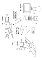
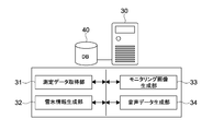
- FIG. 1 is a schematic view showing a configuration example of a snow and ice monitoring system according to a first embodiment of the present invention.
- the snow and ice monitoring system 100 includes a monitoring device 10, an analysis device 30, a database 40, and a display 50.
- the monitoring device 10 is embedded in the runway 1 of the airport (in the ground).
- the monitoring device 10 monitors the condition of the surface 2 of the runway 1 and transmits measurement data on the surface 2 of the runway 1 to the analysis device 30 as a result of the monitoring.
- the surface of the runway 1 corresponds to the surface to be measured.
- measurement data is transmitted via a network such as a wide area network (WAN) or a local area network (LAN).
- WAN wide area network
- LAN local area network
- the measurement data may be transmitted by wireless communication using a high frequency signal or the like.
- any communication form that enables wireless or wired communication may be constructed.
- the analysis device 30 receives the measurement data transmitted from the monitoring device 10.
- the analysis device 30 generates snow and ice information on snow (snow and ice) 3 deposited on the surface 2 of the runway 1 based on the features of the measurement data.
- ice and water are also described as being included in one of the types of snow (one in the state of snow).
- the thickness of snow includes the thickness of ice deposited on the surface 2 of the runway 1.
- the state in which the surface 2 of the runway 1 is wet with water is also regarded as the state in which water, which is one type of snow, is deposited.
- the snow 3 corresponds to a deposit deposited on the surface to be measured.
- snow and ice information corresponds to deposit information on deposits deposited on the surface to be measured.
- the snow and ice information includes, for example, the type of snow 3, the thickness (the amount of deposition), the density, the amount of water, the temperature, the distribution of deposition, and the like. Further, as the snow and ice information, an estimated value of the estimated value of the friction coefficient of the surface 2 of the runway 1 on which the snow 3 is deposited, and an evaluation value obtained by evaluating the state of the runway 1 on which the snow 3 is deposited according to a predetermined standard. As such evaluation value, for example, a runway condition code (RWYCC: Runway Condition Code) defined by the International Civil Aviation Organization (ICAO) is mentioned.
- RWYCC Runway Condition Code
- the evaluation value according to a predetermined standard can also be referred to as a converted amount to a numerical value according to the predetermined standard.
- another evaluation standard, an indicator, etc. may be adopted as a predetermined standard.
- any information about snow 3 such as the outside air temperature may be generated.
- arbitrary information on slipperiness such as arbitrary information that is an indicator of slipperiness, may be generated as deposit information.
- the monitoring result includes both information derived based on the snow and ice information and the snow and ice information itself.
- the analysis device 30 can generate and output at least one of text data, image data, and audio data as output data including snow and ice information.
- a monitoring image 60 including snow and ice information is generated and output to the display 50.
- the manager 5a in the control room or the like of the airport can determine the management guideline or the like of the runway 1 by confirming the monitoring image 60 displayed on the display 50a.
- the image data of the monitoring image 60 is transmitted to the aircraft 6 by radio or the like by the analysis device 30.
- the pilot 5b can determine whether or not to take off and land on the runway 1 by confirming the monitoring image 60 displayed on the display 50b in the cockpit.
- the image data of the monitoring image 60 may be transmitted to the display 50c that can be viewed by the operation manager 5c on the ground.
- the operation manager 5c on the ground can determine whether or not to take off and land on the runway 1 by confirming the monitoring image 60.
- the analysis device 30 may generate audio data including snow and ice information.
- a voice including snow and ice information is output through a speaker in a control room or the like on the ground, such as a control room or the like.
- the manager 5a, the pilot 5b, and the operation manager 5c on the ground can select an appropriate response according to the state of the surface 2 of the runway 1.
- text data including numerical data or the like that is snow and ice information may be generated and output to the display 50.
- text data including snow and ice information is displayed above or below the screen.
- the database 40 stores the measurement data transmitted from the monitoring device 10 and the history of snow / ice information generated by the analysis device 30. In addition, various data used for the snow and ice monitoring system 100 are stored.
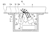
- FIG. 2 is a schematic view showing a configuration example of the monitoring device 10.
- the monitoring device 10 includes a housing 11, a transmission member 12, a transmission unit 13, a reception unit 14, and a control block 15.
- the housing unit 11 has an internal space S, and is embedded inside the runway 1 so that the top surface 11 a of the housing unit 11 has substantially the same height as the surface 2 of the runway 1. Further, an opening 16 is formed on the upper surface 11 a of the housing unit 11.
- the shape of the housing 11 (the shape of the internal space S) and the shape of the opening 16 are not limited.
- the case part 11 which has a cylindrical shape and in which the circular opening 16 is formed may be used.
- the casing 11 having a rectangular parallelepiped shape and having the rectangular opening 16 may be used.
- the transmitting member 12 is a member having transparency, and is fitted into the opening 16 formed in the upper surface 11 a of the housing 11 without a gap.
- the transmitting member 12 is provided at the opening 16 of the housing portion 11 so that the surface 12 a of the transmitting member 12 has the same height as the surface 2 of the runway 1. It becomes possible to acquire measurement data about surface 2 of runway 1 which is a measurement object surface by this.
- the surface 12 a of the transmitting member 12 is a surface included in the surface to be measured. However, the surface 12a does not have to be the same height as the surface 2 of the runway 1, and the heights may be different.
- the specific material of the transmissive member 12 is not limited, and a member having desired resistance such as tempered glass or reinforced plastic may be used appropriately. Moreover, having transparency includes both a transparent state and a semitransparent state with respect to the electromagnetic wave E1, and is not necessarily transparent / semitransparent to visible light.
- the transmission unit 13 is provided at a predetermined position in the internal space S of the housing 11 and has a transmitter 17 that emits an electromagnetic wave E1 as a measurement wave. In the present embodiment, it is possible to emit a plurality of electromagnetic waves E1 having different wavelengths.
- the transmitter 17 is, for example, a laser oscillator, and may itself be capable of emitting laser light of a plurality of different wavelengths. Alternatively, the transmitter unit 13 may be provided with a plurality of transmitters 17 capable of transmitting laser beams of different wavelengths.
- the wavelength band and the wavelength width of the laser beam are not limited, and a broad band laser beam, a narrow band laser beam or the like may be used as the measurement wave (electromagnetic wave E1) as appropriate.
- the configuration of the transmission unit 13 and the type of the electromagnetic wave E1 emitted as the measurement wave are not limited.
- the transmission unit 13 provided with another light source such as an LED or a lamp light source as the transmitter 17 may be used.
- an optical filter or the like capable of controlling the wavelength band, wavelength width, polarization direction, etc. of the electromagnetic wave E1 emitted to the transmitting member 12 may be installed in the transmission unit 13.
- the “electromagnetic wave” includes light of any wavelength range, such as infrared light, visible light, and ultraviolet light.
- the transmitting unit 13 is disposed to be inclined at a predetermined angle toward the lower surface of the transmitting member 12. That is, the transmitting unit 13 is configured such that the incident angle of the electromagnetic wave E1 incident on the lower surface of the transmitting member 12 is inclined.
- the installation angle ⁇ 1 of the transmission unit 13 is schematically illustrated using curved arrows.
- the specific value of the installation angle ⁇ 1 is not limited. For example, assuming that the angle at which the transmitting unit 13 is directed perpendicularly to the lower surface of the transmitting member 12 (the angle at which the electromagnetic wave E1 is vertically incident) is 0 °, the installation angle ⁇ 1 is in the range of 0 ° to 90 ° toward the receiving unit 14 side. It is set.
- the receiving unit 14 is provided at a position facing the transmitting unit 13 in the internal space S of the housing unit 11 at a predetermined distance t.
- the receiving unit 14 has a receiver 18 capable of detecting the intensity distribution of the electromagnetic wave E2 emitted from the lower surface of the transmitting member 12.
- the electromagnetic wave E ⁇ b> 1 emitted from the transmission unit 13 is reflected and scattered by the snow 3 deposited on the surface 12 a of the transmission member 12.
- the scattered wave (scattered light) reflected and scattered by the snow 3 is emitted from the lower surface of the transmitting member 12.
- the electromagnetic wave E2 emitted from the lower surface of the transmitting member 12 may be described as a scattered wave E2 using the same reference numeral.
- the receiver 18 is, for example, a two-dimensional optical sensor such as a CCD or a CMOS camera, and may be capable of detecting a two-dimensional intensity distribution of a plurality of scattered waves E2 different in wavelength by itself.
- a plurality of receivers 18 may be installed in the receiving unit 14, and one-dimensional or two-dimensional intensity distribution of a plurality of scattered waves E2 having different wavelengths as a whole may be detected.
- the configuration of the receiving unit 14 is not limited, and may be arbitrarily configured.
- an optical filter or the like having wavelength selectivity to transmit only the electromagnetic wave E2 to be detected may be installed in the receiving unit 14.
- the receiving unit 14 is disposed to be inclined at a predetermined angle toward the lower surface of the transmitting member 12.
- the installation angle ⁇ 2 of the reception unit 14 is schematically illustrated using curved arrows.
- the specific value of the distance t between the transmission unit 13 and the reception unit 14 and the installation angle ⁇ 2 of the reception unit 14 is not limited.
- the installation angle ⁇ 2 is set in the range of 0 ° to 90 ° toward the transmitting unit 13 side.
- the position and attitude of the transmission unit 13 and the position and attitude of the reception unit 14 may be arbitrarily controlled by a drive mechanism (not shown).
- the installation angle ⁇ 1 of the transmission unit 13, that is, the incident angle of the electromagnetic wave E1 to the transmission member 12 may be arbitrarily controlled.
- the distance t between the transmission unit 13 and the reception unit 14 and the installation angle ⁇ 2 of the reception unit 14 may be arbitrarily controlled. This makes it possible to obtain highly accurate measurement data.
- the drive mechanism can be realized by any actuator mechanism including, for example, a motor and a gear mechanism. Of course any other configuration may be employed. Of course, a configuration may be adopted in which the installation angle ⁇ 1 of the transmission unit 13, the distance t between the transmission unit 13 and the reception unit 14, and the installation angle ⁇ 2 of the reception unit 14 can be changed manually.
- the control block 15 includes a power supply unit (not shown), a control unit, a communication unit, and the like.
- the power supply unit supplies power to the transmission unit 13 and the reception unit 14.
- the specific configuration of the power supply unit is not limited.
- the control unit controls the operation of each of the transmission unit 13 and the reception unit 14 to execute emission of an electromagnetic wave E1 of a predetermined wavelength, and intensity detection of a two-dimensional distribution of a scattered wave E2 of a predetermined wavelength.
- the control unit transmits measurement data including the intensity signal (measurement signal) obtained by the receiver 18 of the receiving unit 14 to the analyzer 30 shown in FIG. 1 via the communication unit.
- the control unit has, for example, a hardware configuration necessary for a computer such as a CPU and a memory (RAM, ROM).
- a device such as a PLD (Programmable Logic Device) such as an FPGA (Field Programmable Gate Array) or another application specific integrated circuit (ASIC) may be used.
- a communication unit arbitrary configurations, such as arbitrary wireless modules, may be used, for example.
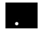
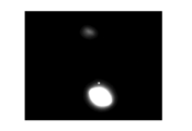
- FIG. 3 to 5 are photographs showing an example of measurement data transmitted from the monitoring device 10 to the analysis device 30.
- FIG. In the present embodiment two-dimensional intensity distributions of scattered waves E2 of different wavelengths are transmitted as measurement data.
- an image signal including intensity information (luminance information) of each pixel generated by the receiver 18 is transmitted as measurement data.
- the image signal generated by the receiver 18 corresponds to measurement image data obtained by irradiating a measurement wave toward the surface to be measured.
- the image signal is referred to as measurement image data.
- FIGS. 3 to 5 are diagrams showing images generated based on measurement image data obtained when electromagnetic waves E1 having different wavelengths are irradiated in a state where snow 3 is deposited on the transmitting member 12. .
- this image itself may be described as measurement image data.
- the electromagnetic wave E1 emitted toward the transmitting member 12 is reflected and scattered by the snow 3 and emitted from the transmitting member 12 toward the receiving unit 14 as a scattered wave E2.
- An image signal of the scattered wave E2 reflected and scattered by the snow 3 is generated as measurement image data.
- three types of images (image signals) shown in FIGS. 3 to 5 are generated by emitting electromagnetic waves E1 having different first to third wavelengths ⁇ 1 to ⁇ 3.
- These images are two-dimensional light scattering images of the scattered wave E2 obtained by emission of the electromagnetic wave E1. That is, it is a two-dimensional light scattering image of each of the scattered waves E2 of the first to third wavelengths ⁇ 1 to ⁇ 3.
- These three types of two-dimensional light scattering images (image signals) are transmitted to the analysis device 30 as measurement image data.
- the three types of measurement image data correspond to a plurality of measurement data corresponding to a plurality of electromagnetic waves obtained by irradiating a plurality of electromagnetic waves having different wavelengths toward the surface to be measured.
- the plurality of measurement data are not limited to three types of measurement image data, and two or more arbitrary numbers of measurement image data may be generated.
- only one type of measurement image data obtained by being irradiated with an electromagnetic wave of one type of wavelength may be transmitted to the analysis device 30, and snow and ice information may be generated.
- FIG. 6 is a block diagram showing a functional configuration example of the analysis device 30.
- the analysis device 30 has hardware necessary for the configuration of the computer, such as a CPU, a ROM, a RAM, and an HDD.
- a PC Personal Computer
- any other computer may be used.
- the CPU loads a program according to the present technology stored in the ROM or the HDD into the RAM and executes the program to obtain the measurement data acquisition unit 31, the snow and ice information generation unit 32, and the monitoring image generation unit which are functional blocks shown in FIG. 33 and an audio data generation unit 34 are realized. And the information processing method concerning this art is performed by these functional blocks. Dedicated hardware may be used as appropriate to realize each functional block.
- the analysis device 30 corresponds to an information processing device.
- the program is installed in the analysis device 30 via, for example, various recording media. Alternatively, the program may be installed via the Internet or the like.
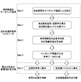
- FIG. 7 is a flowchart showing an example of the snow and ice monitoring operation.
- the “runway snow and ice monitoring device” in the figure corresponds to the monitoring device 10, and the “snow and ice condition analysis computer” corresponds to the analysis device 30.
- the “snow and ice condition and control pointer display” in the figure corresponds to the display 50 shown in FIG.
- measurement is first performed by the monitoring device 10 as Step 0. Specifically, measurement image data of snow 3 deposited on the surface 12 a of the transmission member 12 is generated. In this embodiment, three types of measurement image data obtained by emitting the electromagnetic waves E1 of the first to third wavelengths ⁇ 1 to ⁇ 3 as illustrated in FIGS. Will be sent.
- the transmitted measurement image data is acquired by the measurement data acquisition unit 31 shown in FIG. In the present embodiment, the measurement data acquisition unit 31 functions as an acquisition unit.
- step 1 snow and ice information on snow deposited on the transmission member 12 (snow deposited on the surface 2 of the runway 1) is generated by the analysis device 30 based on the features of the measurement image data.
- the type of snow 3 (snow quality) and the thickness of the snow 3 (snow thickness) are first calculated by the snow and ice information generation unit 32 shown in FIG. 6.
- snow quality for example, “frost (FROST)” "dry snow (DRY SNOW)” “slash (SLUSH)” “wet snow (WET SNOW)” “compressed snow” “ice (ICE)” " It includes arbitrary snow conditions such as new snow (FRESH) and “smooth snow (GRANULAR)”.
- snow and ice information regarding snow information such as “DRY” which is a state without snow, or information such as “wet (DRY)” and “STANDING WATER” may be generated. These pieces of information may be treated in the same manner as the snow quality information.
- snow thickness for example, information in mm is generated.
- snow thickness information may be generated in units of arbitrary thickness such as 5 mm, 10 mm, 50 mm, and the like.
- a method of calculating the snow quality and the snow thickness will be described based on the characteristics of the image measurement data exemplified in FIGS. 3 to 5.
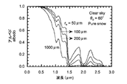
- FIG. 8 is a graph showing an example of a snowfall radiative transfer model.
- the albedo ratio of reflected light to incident light
- re 50 ⁇ m in the figure corresponds to fresh snow, and 1000 ⁇ m corresponds to rough snow.
- the amount of light reflected / scattered largely changes with respect to snow quality and wavelength, and snow thickness and snow quality can be calculated from the relationship of reflection / scattering intensity to light wavelength.
- the quality of the snow (including ice and water) 3 present on the transmitting member 12 by irradiating the electromagnetic waves E1 of a plurality of different wavelengths and detecting the two-dimensional intensity distribution of the scattered waves E2 for each wavelength It is possible to separate and determine the thickness accurately. As a result, it becomes possible to monitor the state regarding snow 3 in detail.
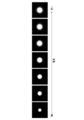
- FIG. 9 is a photograph showing measurement image data in the case where the electromagnetic wave E1 of the same wavelength is irradiated to the snow 3 different in thickness.
- the amount of the scattered wave E2 reflected and scattered by the snow 3 increases. Accordingly, the amount of the scattered wave E2 emitted from the transmitting member 12 toward the receiving unit 14 increases, and the maximum diameter (maximum diameter of the light receiving area) of the scattered wave E2 included in the measurement image data increases. That is, since the maximum diameter of the scattered wave E2 changes according to the snow thickness, it is possible to monitor the snow thickness with high accuracy based on the feature of the measurement image data.
- the amount of the scattered wave E2 reflected and scattered by the snow 3 changes in accordance with the change in the water content (water content) and particle size of the snow 3 deposited on the transmitting member 12. Therefore, it is possible to monitor not only the snow thickness but also the water content and particle size with high accuracy based on the characteristics of the measurement image data. Based on the water content and particle size, it is possible to identify snow quality such as the aforementioned "dry snow (DRY SNOW)".
- an electromagnetic wave of a wavelength where the amount of light reflected / scattered largely changes according to a change of snow thickness and an electromagnetic wave of a wavelength where an amount of light reflected / scattered largely changes according to a change of water content
- Three types of electromagnetic waves E1 of an electromagnetic wave of a wavelength where the amount of light reflected and scattered largely changes according to a change in particle diameter are used as measurement waves.
- the threshold value regarding a luminance value may be set in each pixel of the receiver 18. An image signal may be generated with zero luminance for luminance values below the threshold. This makes it possible to improve the accuracy of monitoring based on the maximum diameter of the scattered wave E2.
- the snow thickness, the water content, and the particle size correspond to a plurality of different types of deposit information corresponding to a plurality of measurement image data.
- the specific wavelength values for monitoring each of the snow thickness, the water content, and the particle diameter with high accuracy can be appropriately set by calibration or the like.
- Information calculated as snow and ice information is not limited to snow thickness, water content, and particle size, and other parameters such as density, temperature, uniformity of particles, etc. may be calculated.
- the wavelength of the electromagnetic wave E1 it is possible to calculate an arbitrary parameter that changes the absorption characteristic and the scattering characteristic of the snow 3 based on the feature of the measurement image data.
- the characteristics of the measurement image data include not only the maximum diameter of the scattered wave E2, but also the position, area (area of the light receiving area), shape (flatness, roundness, etc.) of the scattered wave E2, and inclination of intensity in the light receiving area (Slope of luminance), the intensity of the central portion of the light receiving area, the average of the intensity, or any other characteristic regarding the two-dimensional distribution such as the intensity (luminance) may be adopted. This makes it possible to monitor snow thickness, water content, and particle size with high accuracy.
- the snow and ice information generation unit 32 generates snow and ice information according to a predetermined machine learning algorithm.
- machine learning algorithm using DNN such as RNN (Recurrent Neural Network), CNN (Convolutional Neural Network), MLP (Multilayer Perceptron), etc. Is used.
- DNN Deep Neural Network
- CNN Convolutional Neural Network
- MLP Multilayer Perceptron
- any machine learning algorithm that executes supervised learning method, unsupervised learning method, semi-supervised learning method, reinforcement learning method and the like may be used.
- an AI Artificial Intelligence
- deep learning deep learning
- feature amounts defined by an operator or the like for performing learning by a machine learning algorithm, and feature amounts extracted by the algorithm are also included in the features of the measurement image data according to the present embodiment.
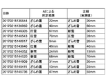
- FIG. 10 is a table showing the identification results for actual snow cover. As for snow quality and snow thickness, it is understood that the identification result by AI is very close to the measured value. It is also possible to obtain a more accurate identification result by appropriately constructing a machine learning algorithm.
- Step 1 linking the calculated snow quality and thickness with the runway status code is executed as Step 1. That is, a runway state code is generated as snow and ice information.
- the method of linking these pieces of information is not limited.
- the snow quality and thickness necessary to derive the runway status code may be directly calculated, or the snow quality and thickness calculated in step 1 may be appropriately calculated to derive the runway status code. It may be converted.
- other parameters such as the outside temperature may be referred to as appropriate to derive the runway status code.
- step 2 the analysis device 30 determines the need for snow removal on the runway 1. Further, it is determined whether or not the runway 1 is to be taken off and land. These processes are typically performed based on the snow quality and thickness and the runway status code calculated in step 1.
- step 2 is also executed by the snow and ice information generation unit 32. That is, in the present embodiment, information indicating whether there is a need for a snow removal operation and whether takeoff and landing are possible is generated as snow and ice information on snow 3 deposited on the transparent member 12 (snow deposited on runway 1) 3 . Thus, information on the management guidelines, judgment information on operation, etc. may be generated as snow and ice information.
- Information indicating whether or not the snow removal work is necessary directly based on the measurement image data acquired in step 0, not the snow quality and snow thickness generated in step 1, but the runway status code, And information indicating whether take-off and landing are possible may be generated.
- a predetermined machine learning algorithm may be used.
- step 3 the analysis device 30 generates output data including the snow and ice information generated in steps 1 and 2.
- the monitoring image generation unit 33 generates a monitoring image 60 including snow and ice information.
- the audio data generation unit 34 generates audio data including snow and ice information.
- the monitoring image generation unit 33 and the audio data generation unit 34 function as an output unit.
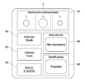
- FIG. 11 is a schematic view showing an example of the monitoring image 60.
- the monitoring image 60 includes a measurement image data display unit 61, a snow quality (type of snow) display unit 62, a snow thickness display unit 63, a runway status code display unit 64, a snow removal necessity display unit 65, takeoff and landing An availability display unit 66 is provided.
- the measurement image data display unit 61 displays the measurement image data transmitted from the monitoring device 10. In the present embodiment, three types of two-dimensional light scattering images illustrated in FIGS. 3 to 5 are displayed.
- the snow quality display unit 62 displays the snow quality calculated in step 1.
- the snow thickness display section 63 displays the snow thickness calculated in step 1.
- the runway status code display unit 64 displays the runway status code generated in step 1.
- the snow removal necessity display section 65 the presence or absence of the necessity of the snow removal work generated as snow and ice information in step 2 is displayed.
- the takeoff / landing availability display unit 66 displays information indicating whether takeoff or landing, which is generated as snow and ice information in step 2, is possible.
- the monitoring image 60 is output and displayed on the display 50a that can be viewed by the manager 5a of the airport (runway 1). Moreover, the monitoring image 60 is displayed on the display 50b which can view the pilot 5b of an aircraft. Of course, the monitoring image 60 may be displayed on the display 50c that can be viewed by the operation manager 5c on the ground.
- the manager 5a, the pilot 5b, and the operation manager 5c on the ground can easily grasp the state of the surface 2 of the runway 1, and the management guidelines and the like are easily made. It is possible to decide on For example, the manager 5a can easily determine the necessity of snow removal, and can easily manage the runway 1 based on the runway status code. Further, the pilot 5b of the aircraft can easily determine whether or not the runway 1 can be taken off and land without directly confirming the surface 2 of the runway 1. Of course, it becomes possible to perform operations etc. based on the runway status code. In addition, the operation manager 5c on the ground can easily determine whether or not to take off and land on the runway 1, and, for example, it is possible to comprehensively determine an appropriate response together with the result of direct confirmation on the site. It becomes possible.
- step 4 audio data including snow and ice information may be generated.
- a voice including snow and ice information is output through a speaker in a control room or the like on the ground, such as a control room or the like.
- the manager 5a, the pilot 5b, and the operation manager 5c on the ground can select an appropriate response according to the state of the surface 2 of the runway 1.
- the configuration of the monitoring image 60 is not limited, and an arbitrary image (GUI) may be generated and displayed. Also, the snow and ice information included in the monitoring image 60 is not limited, and arbitrary snow and ice information may be displayed.
- the present invention is not limited to the case where the same monitoring image 60 is generated, and a monitoring image for management to be provided to the administrator 5a, a monitoring image for pilot to be provided to the pilot 5b, and a ground operation manager 5c.
- the operation manager monitoring images to be provided to each may be separately configured.
- the monitoring image 60 may be freely customizable by the manager 5a, the pilot 5b, and the operation manager 5c on the ground. That is, snow and ice information to be confirmed may be appropriately selected.
- the contents (letters, symbols, images) of the snow ice information to be displayed, its arrangement, size, color arrangement, etc. may be manually or automatically changeable according to the environment or situation.
- the audio data the audio content may be changed as appropriate based on the environment, the situation, the generated snow and ice information and the like. For example, a warning or information to be transmitted may be appropriately determined, and audio data to be output may be appropriately generated.
- a plurality of monitoring devices 10 are often installed at a plurality of locations of the runway 1.
- a monitoring image 60 illustrated in FIG. 11 may be generated. This makes it possible to grasp the surface condition at each point of the runway 1.
- snow and ice information generated based on measurement data measured by each monitoring device 10 may be integrated, and a monitoring image 60 including the integrated snow and ice information may be generated.
- the surface condition (snow and ice information) at each point may be integrated to generate and display snow quality, snow thickness, runway condition code, necessity of snow removal, and availability of takeoff and landing. Thereby, it is possible to grasp the entire state of the runway 1.
- the method of integrating a plurality of pieces of snow and ice information is not limited, and information obtained by averaging snow quality and thickness of each point is displayed.
- weighting may be performed depending on the point at which the monitoring device 10 is installed. For example, the measurement data of the monitoring device 10 installed at the center of the runway 1 and the snow and ice information generated therefrom are weighted heavily. On the other hand, the measurement data etc. of the monitoring device 10 installed at the position of the end of the runway 1 has a small weighting. Such processing is also possible.
- snow and ice information may be generated and displayed for each area of runway 1.
- snow ice information is generated based on the measurement data transmitted from the monitoring device 10 and displayed in the monitoring image 60.
- measurement data and snow and ice information are integrated and displayed in the monitoring image 60.
- the information with the worst state may be selected and displayed in the monitoring image 60.
- the information with the worst state may be selected and displayed in the monitoring image 60. For example, it is assumed that snow ice information is generated for one point that snow removal is necessary and take-off and landing are impossible. In this case, even if snow and ice information indicating that there is no need for snow removal and take-off and landing is generated for multiple other points, snow and ice information indicating that take-off and landing is not possible is displayed. Be done. Such processing is also possible.
- prediction information for predicting the state of the surface 2 of the runway 1, which is the surface to be measured based on at least one of measurement data (measurement image data) acquired from the monitoring device 10 and generated snow and ice information It is possible to generate. For example, it is possible to generate prediction information for predicting how snow quality, snow thickness, runway status code, necessity of snow removal work, and whether or not takeoff and landing are transitioning in the future.
- the prediction information is generated based on, for example, measurement data stored in the database 40 shown in FIG. 1, historical information such as snow and ice information, and the like, a predetermined prediction model, prediction data, and the like. For example, it is possible to generate prediction information including snow quality and thickness such as after 10 minutes, 30 minutes, 60 minutes, etc. based on weather information etc. acquired via a weather radar etc. installed at an airport It is. Of course, any machine learning algorithm may be used to generate prediction information. By generating prediction information, it is possible to accurately determine airport management guidelines, operation plans and the like.
- Predicted measurement data on the surface 2 of the runway 1, which is the surface to be measured may be generated based on the characteristics of the measurement data acquired from the monitoring device 10. For example, predictive measurement data is generated to predict how the two-dimensional light scattering image changes as illustrated in FIGS. 3-5. And prediction information may be generated based on this prediction measurement data.
- snow and ice information is produced
- the surface 2 of runway 1 It becomes possible to grasp the state of the very accurately.
- the monitoring device 10 is embedded inside the runway 1, it is possible to avoid an obstacle to the aircraft. In addition, it is possible to monitor the detailed condition of snow depth and quality on the entire runway while preventing damage etc. due to the collision of foreign matter from the outside.
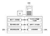
- FIG. 12 is a block diagram showing a functional configuration example of the analysis device 230 according to the present embodiment.
- the analyzer 230 has a measurement wavelength determination unit 235 and an external control unit 236 as functional blocks.
- the measurement wavelength determination unit 235 determines the characteristics of the measurement wave emitted from the transmitter 17 of the monitoring device 10 based on at least one of the measurement data (measurement image data) acquired from the monitoring device 10 and the generated snow and ice information. It is possible to make a decision.
- the measurement wavelength determination unit 235 corresponds to a setting unit.
- the wavelength to be used for measurement is selected from the plurality of wavelengths.
- the electromagnetic waves E1 of the first to third wavelengths ⁇ 1 to ⁇ 3 having different absorption, scattering, and reflection characteristics are emitted, the first wavelength ⁇ 1, the second wavelength ⁇ 2, and the third wavelength It is possible to select each of ⁇ 3 appropriately from a plurality of wavelengths.
- the first wavelength ⁇ 1, the second wavelength ⁇ 2, and the third wavelength ⁇ 3 may be within the wavelength range. Each is determined appropriately.
- a wavelength necessary for measurement may be selected from the first wavelength ⁇ 1, the second wavelength ⁇ 2, and the third wavelength ⁇ 3 in accordance with the measured snow quality and thickness.
- the wavelength of the electromagnetic wave E1 is appropriately selected from the first wavelength ⁇ 1, the second wavelength ⁇ 2, and the third wavelength ⁇ 3 so that desired snow / ice information can be obtained according to the state of the snow 3 .
- Such processing is also possible.
- the characteristics of the measurement wave emitted from the transmitter 17 such as the wavelength of the electromagnetic wave E1 can be set by the operation of the administrator 5a or a specialized operator or the like, which is input via a predetermined computer such as a PC. It is also good. That is, the characteristics of the measurement wave may be changeable manually.
- a specific example of setting of the wavelength of the electromagnetic wave E1 will be described.
- a wavelength suitable for snow thickness observation is selected in advance (a visible wavelength more likely to flow in the snow layer, etc.).
- a wavelength suitable for measuring the water content water content ratio
- the wavelength of the electromagnetic wave E1 based on the result of the snow thickness. For example, when snow thickness is first measured at a certain wavelength, it is determined that only thin snow thickness is accumulated. In this case, since it is necessary to measure the snow quality of the surface layer rather than the thickness of the snow, it shifts to the measurement by the wavelength such as near infrared which is effective for the particle size determination. When it is judged that the snow thickness is thick to some extent, emphasis is placed on snow thickness measurement by selecting a visible wavelength or the like that can penetrate the snow layer rather than the near infrared wavelength.
- the wavelength of the electromagnetic wave E1 based on the result of the moisture content. For example, when the moisture content is first measured at a certain wavelength, it is assumed that the moisture content is determined to be high to some extent. In this case, since an error may occur due to the moisture content in optical observation of the snow quality, a wavelength effective for moisture content measurement and a wavelength effective for snow quality measurement are simultaneously selected to compensate for the error. If it is determined that the moisture content is at a level not affected by the error, only the wavelength effective for snow quality observation is selected and the snow quality is mainly measured.
- the characteristic of the measurement wave is not limited to the wavelength of the electromagnetic wave E1, and any characteristic such as the intensity of the electromagnetic wave E1, the polarization state, and the pulse interval may be determined. Also, any machine learning algorithm may be used to set the characteristics of the measurement wave.
- the intensity of the electromagnetic wave E1 and the gain of the receiver 18 may be manually or automatically selectable based on measurement data, snow and ice information, and the like. For example, when a range over (saturation) portion exists in the measurement data, the intensity (brightness) of the electromagnetic wave E1 is lowered and the gain of the receiver 18 is decreased. If the entire measurement data is smaller than a predetermined threshold, the intensity (luminance) of the electromagnetic wave E1 is increased and the gain of the receiver 18 is decreased. As described above, by appropriately changing the strength and the gain from the tendency of the measurement data, the optimum measurement can be performed.
- the intensity of the electromagnetic wave E1 or the gain of the receiver 18 may be changed based on external weather information or the like. For example, if the external environmental light is strong and the value of the measurement data is large, the intensity (luminance) of the electromagnetic wave E1 is increased and the gain of the receiver 18 is decreased to improve the S / N of the data. . Such processing is also possible.
- the external control unit 236 generates control information for controlling an external device based on at least one of the measurement data (measurement image data) acquired from the monitoring device 10 and the generated snow and ice information. For example, the external control unit 236 can transmit a signal for controlling an external device according to the measurement data and the snow and ice information processed by the environment or situation and analysis device 230.
- the external control unit 236 corresponds to a control information generation unit.
- FIG. 13 is a schematic view showing a configuration example of a monitoring device according to another embodiment.
- the monitoring device 310 includes a housing 311, a transmitting member 312, a transmitting unit 313, a plurality of receiving units 314, and a control block 315.
- the plurality of receiving units 314 are arranged in five rows from the transmitting unit 313 side. By installing a plurality of receiving units 314 in this manner, it becomes possible to measure the snow quality and thickness for a wide range of snow 3 and monitor the state of the surface 2 of the runway 1 with high accuracy. It becomes possible.
- the scope to which the technology can be applied is not limited to snow and ice monitoring of airport runways. It is applicable to monitoring the surface condition of other structures such as roads, bridges and buildings. Further, the present invention is not limited to take-off and landing of an aircraft, and may be applied to determination regarding the traveling of another moving object such as a vehicle. Also, with regard to deposits, it is possible to apply the present technology to any deposits such as snow, ice, water, mud, volcanic ash and the like. That is, the present technology is applicable to various fields.
- a monitoring device on the road surface, it is possible to display the surface condition of snow, sand, etc. on the road surface to the road administrator and utilize it for road management. For example, it becomes possible to easily carry out judgment of necessity of blockade of a road, selection of a detour etc. Further, by displaying a monitoring image or the like on a display panel of a general automobile, it is possible to notify the driver of the condition of the road surface in real time through, for example, a network or the like, and prevent accidents and improve traffic efficiency. Further, not only real-time surface condition but also road surface condition prediction display combined with prediction model of future snowfall condition etc. can be applied, and traffic efficiency can be further improved.
- information on the layer structure of the deposit may be generated. For example, changes in the quality of snow or volcanic ash in the thickness direction, the state of each layer to be stacked, or the like may be generated as deposit information.
- a plurality of measurement data corresponding to a plurality of electromagnetic waves are acquired by irradiating a plurality of electromagnetic waves having different wavelengths toward the surface to be measured.
- the invention is not limited thereto, and a plurality of electromagnetic waves having different wavelength bands or wavelength widths may be irradiated toward the surface to be measured, and a plurality of measurement data corresponding to the plurality of electromagnetic waves may be acquired.
- a broad band laser beam, a narrow band laser beam or the like is irradiated as a plurality of measurement waves (electromagnetic waves E1), and a plurality of measurement data corresponding to these laser beams are generated. Then, a plurality of deposit information corresponding to a plurality of measurement data may be generated.
- deposit information is generated based on one type of measurement data obtained by irradiation with one type of electromagnetic wave, such as an electromagnetic wave of a predetermined wavelength (single wavelength), an electromagnetic wave of a predetermined wavelength band, an electromagnetic wave of a predetermined wavelength width. It is also possible.
- the monitoring apparatus may have a configuration including a transmission unit capable of irradiating an electromagnetic wave in a linear polarization state and a reception unit capable of detecting an electromagnetic wave in a linear polarization state in a specific direction.
- the polarization direction of the emitted electromagnetic wave and the detectable polarization direction of the electromagnetic wave are set so as to have a substantially orthogonal Nicol relationship that is substantially orthogonal to each other.
- the monitoring device may be configured to be portable. This makes it possible, for example, to carry and install the monitoring device on a snowy mountain or a land near a volcano. And based on the measurement data transmitted from a monitoring apparatus, it becomes possible to monitor the state of the desired surface with high precision. For example, information such as the possibility of occurrence of an avalanche or the possibility of an eruption can be generated as deposit information or its prediction information.
- generates measurement data by irradiating electromagnetic waves was mentioned.
- the present invention is not limited to this, and another sensor device or the like that can measure the outside air temperature or the like as measurement data may be used as the monitoring device.
- the temperature which is measurement data may be used as it is as snow and ice information.
- a device that outputs text data as measurement data may be used as the monitoring device.
- a configuration may be employed in which text data is generated based on measurement data obtained by any measurement method, and the text data is output as measurement text data.
- arbitrary data may be output as measurement data. Similar to the plurality of measurement image data described above, a plurality of measurement text data may be output, and a plurality of deposit information corresponding to the plurality of measurement text data may be generated.
- an analysis device has been exemplified as an embodiment of the information processing device according to the present technology.
- the information processing method according to the present technology may be executed by a cloud server without being limited to this.
- the information processing method according to the present technology may be executed by interlocking a plurality of computers that can communicate with each other.
- the information processing method according to the present technology by the computer system and the execution of the program are both performed when processing such as generation of deposit information is executed by a single computer and when each processing is executed by a different computer. Including. Also, execution of each process by a predetermined computer includes performing a part or all of the process on another computer and acquiring the result.
- the information processing method and program according to the present technology can be applied to the configuration of cloud computing in which one function is shared and processed by a plurality of devices via a network.
Landscapes
- Physics & Mathematics (AREA)
- General Physics & Mathematics (AREA)
- Life Sciences & Earth Sciences (AREA)
- Engineering & Computer Science (AREA)
- Immunology (AREA)
- Pathology (AREA)
- General Health & Medical Sciences (AREA)
- Health & Medical Sciences (AREA)
- Chemical & Material Sciences (AREA)
- Analytical Chemistry (AREA)
- Biochemistry (AREA)
- Environmental & Geological Engineering (AREA)
- Mechanical Engineering (AREA)
- Transportation (AREA)
- Atmospheric Sciences (AREA)
- Environmental Sciences (AREA)
- Ecology (AREA)
- Biodiversity & Conservation Biology (AREA)
- Spectroscopy & Molecular Physics (AREA)
- Hydrology & Water Resources (AREA)
- Automation & Control Theory (AREA)
- Mathematical Physics (AREA)
- Investigating Or Analysing Materials By Optical Means (AREA)
- Length Measuring Devices By Optical Means (AREA)
- Investigating Materials By The Use Of Optical Means Adapted For Particular Applications (AREA)
Priority Applications (1)
| Application Number | Priority Date | Filing Date | Title |
|---|---|---|---|
| US16/757,900 US11635373B2 (en) | 2017-10-27 | 2018-08-29 | Information processing apparatus, information processing method, program, and monitoring system |
Applications Claiming Priority (2)
| Application Number | Priority Date | Filing Date | Title |
|---|---|---|---|
| JP2017208077A JP7056905B2 (ja) | 2017-10-27 | 2017-10-27 | モニタリングシステム、情報処理方法、及びプログラム |
| JP2017-208077 | 2017-10-27 |
Publications (1)
| Publication Number | Publication Date |
|---|---|
| WO2019082504A1 true WO2019082504A1 (ja) | 2019-05-02 |
Family
ID=66247269
Family Applications (1)
| Application Number | Title | Priority Date | Filing Date |
|---|---|---|---|
| PCT/JP2018/031949 Ceased WO2019082504A1 (ja) | 2017-10-27 | 2018-08-29 | 情報処理装置、情報処理方法、プログラム、及びモニタリングシステム |
Country Status (3)
| Country | Link |
|---|---|
| US (1) | US11635373B2 (https=) |
| JP (1) | JP7056905B2 (https=) |
| WO (1) | WO2019082504A1 (https=) |
Cited By (3)
| Publication number | Priority date | Publication date | Assignee | Title |
|---|---|---|---|---|
| CN113340812A (zh) * | 2021-06-03 | 2021-09-03 | 武汉致腾科技有限公司 | 一种基于多光谱的路面水冰雪识别装置 |
| CN113994170A (zh) * | 2019-06-19 | 2022-01-28 | 罗伯特·博世有限公司 | 用于确定车辆已驶过的或车辆将驶过的车道的表面状态的设备和方法 |
| EP4150161B1 (en) | 2020-05-15 | 2025-07-02 | PRINOTH S.p.A. | Snow groomer vehicle and method of controlling a snow groomer vehicle |
Families Citing this family (8)
| Publication number | Priority date | Publication date | Assignee | Title |
|---|---|---|---|---|
| JP7356680B2 (ja) * | 2019-09-12 | 2023-10-05 | 国立大学法人 熊本大学 | 摩擦状態推定システム及び摩擦状態推定方法 |
| JP7382038B2 (ja) * | 2019-11-28 | 2023-11-16 | 国立研究開発法人宇宙航空研究開発機構 | 情報処理システム、情報処理装置、情報処理方法、及びプログラム |
| JP7383247B2 (ja) * | 2019-11-28 | 2023-11-20 | 国立研究開発法人宇宙航空研究開発機構 | 情報処理システム、情報処理装置、情報処理方法、及びプログラム |
| JP7310688B2 (ja) * | 2020-04-07 | 2023-07-19 | Jfeエンジニアリング株式会社 | 排ガス通路内壁面の付着物厚み推定方法及び装置 |
| JP7527655B2 (ja) * | 2021-11-22 | 2024-08-05 | 山田技研株式会社 | 滑走路の積雪深計測方法及び計測装置 |
| EP4212848B1 (en) * | 2022-01-14 | 2025-01-01 | Eidg. Forschungsanstalt für Wald, Schnee und Landschaft WSL | Snow density measurement instrument |
| US12007248B2 (en) | 2022-03-03 | 2024-06-11 | Ford Global Technologies, Llc | Ice thickness estimation for mobile object operation |
| WO2025042876A1 (en) * | 2023-08-21 | 2025-02-27 | Arizona Board Of Regents On Behalf Of The University Of Arizona | Liquid phase discrimination using polarimetry |
Citations (3)
| Publication number | Priority date | Publication date | Assignee | Title |
|---|---|---|---|---|
| JP2008180623A (ja) * | 2007-01-25 | 2008-08-07 | Nagoya Electric Works Co Ltd | 路面状態判別装置および路面状態判別方法 |
| US20160140854A1 (en) * | 2013-04-29 | 2016-05-19 | Honeywell International Inc. | Methods and apparatus for determining and using a landing surface friction condition |
| JP2016170069A (ja) * | 2015-03-13 | 2016-09-23 | 国立研究開発法人宇宙航空研究開発機構 | 雪氷モニタ装置 |
Family Cites Families (36)
| Publication number | Priority date | Publication date | Assignee | Title |
|---|---|---|---|---|
| JPS62217144A (ja) * | 1986-03-19 | 1987-09-24 | Fuji Photo Film Co Ltd | 化学分析用測光部 |
| US4797660A (en) * | 1987-03-03 | 1989-01-10 | Rein Jr Robert G | Photoelectric ice accumulation monitor using dual detectors |
| DE4008280A1 (de) * | 1990-03-15 | 1991-09-19 | Tzn Forschung & Entwicklung | Verfahren zur ermittlung des fahrbahnoberflaechenzustandes |
| US5483346A (en) * | 1994-04-11 | 1996-01-09 | Butzer; Dane C. | Polarization based optical sensor utilizing total internal reflection |
| DE19506550A1 (de) * | 1995-02-24 | 1996-08-29 | Inst Chemo Biosensorik | Verfahren zur verzugsfreien Feststellung von und zur Warnung vor durch Glättebildung bedingte Gefahren und Vorrichtung zur Durchführung des Verfahrens |
| US5781115A (en) * | 1995-04-03 | 1998-07-14 | Target Microwave | Apparatus and method for detection and thickness measurement of coatings over a surface |
| US5596320A (en) * | 1995-04-28 | 1997-01-21 | Optical Sensor Consultants Inc. | System for detection of ice, water, glycol solution, and other chemical species |
| US5748091A (en) * | 1996-10-04 | 1998-05-05 | Mcdonnell Douglas Corporation | Fiber optic ice detector |
| KR19990063054A (ko) * | 1997-12-17 | 1999-07-26 | 마쯔무라 미노루 | 레인 센서의 출력 안정화방법 및 보호방법 |
| US6262407B1 (en) * | 1998-12-31 | 2001-07-17 | Libbey-Owens-Ford Co. | Moisture sensor with automatic emitter intensity control |
| JP2000258557A (ja) * | 1999-03-12 | 2000-09-22 | Matsushita Electric Ind Co Ltd | 降雪センサ |
| US6430996B1 (en) * | 1999-11-09 | 2002-08-13 | Mark Anderson | Probe and integrated ice detection and air data system |
| US6606035B2 (en) * | 2000-11-17 | 2003-08-12 | Safe Landing Systems Inc. | System and method for airport runway monitoring |
| US6819265B2 (en) * | 2002-08-22 | 2004-11-16 | Rosemount Aerospace Inc. | Advanced warning ice detection system for aircraft |
| SE524878C2 (sv) * | 2002-10-10 | 2004-10-19 | Ulf Elman | Anordning, metod och system för att bestämma en vägytas tillstånd med våglängdsmodulerad spektrometri |
| JP3988828B2 (ja) * | 2004-01-26 | 2007-10-10 | 独立行政法人電子航法研究所 | 誘電率の測定方法及び誘電率測定装置 |
| US7265846B2 (en) * | 2004-02-03 | 2007-09-04 | Sensors Unlimited, Inc. | Methods for detecting ice and liquid water on surfaces |
| US7586422B2 (en) * | 2006-08-02 | 2009-09-08 | The Boeing Company | Determination of runway landing conditions |
| JP5174034B2 (ja) * | 2006-12-19 | 2013-04-03 | エンジニアード・アレスティング・システムズ・コーポレーション | 情報、詳しくは着陸航空機のパイロットに利用可能な滑走路状態に関する情報を改善又は増加するシステム及び方法 |
| FR2930669B1 (fr) * | 2008-04-24 | 2011-05-13 | Airbus France | Dispositif et procede de determination d'un etat de piste, aeronef comprenant un tel dispositif et systeme d'aide au pilotage exploitant cet etat de piste |
| US20100039294A1 (en) * | 2008-08-14 | 2010-02-18 | Honeywell International Inc. | Automated landing area detection for aircraft |
| US8773289B2 (en) * | 2010-03-24 | 2014-07-08 | The Boeing Company | Runway condition monitoring |
| FR2978736B1 (fr) * | 2011-08-01 | 2013-09-27 | Airbus Operations Sas | Dispositif et procede de determination d'un etat de piste, aeronef comprenant un tel dispositif et systeme d'aide au pilotage exploitant cet etat de piste |
| JP2014052364A (ja) * | 2012-08-09 | 2014-03-20 | Ricoh Co Ltd | 付着物検出装置、移動装置用機器制御システム及び移動装置 |
| US9663223B1 (en) * | 2013-02-11 | 2017-05-30 | The Boeing Company | Aircraft braking performance and runway condition determination |
| JP6326729B2 (ja) * | 2013-06-13 | 2018-05-23 | 国立研究開発法人宇宙航空研究開発機構 | 路面および構造物表面の雪厚と雪質モニタリングセンサー |
| US20160196754A1 (en) * | 2015-01-06 | 2016-07-07 | Honeywell International Inc. | Airport surface monitoring system with wireless network interface to aircraft surface navigation system |
| FR3040371B1 (fr) * | 2015-09-02 | 2017-10-06 | Airbus Operations Sas | Procede et dispositif de determination automatique d'un etat de piste. |
| US20170115215A1 (en) * | 2015-10-26 | 2017-04-27 | Jeffrey Scott Adler | Sensor for detecting remotely located reflective material |
| JP6361631B2 (ja) | 2015-10-29 | 2018-07-25 | Smk株式会社 | 車載センサ、車両用灯具及び車両 |
| US10576948B2 (en) * | 2015-12-08 | 2020-03-03 | Airbus Group India Private Limited | Aircraft braking based on real time runway condition |
| US10202204B1 (en) * | 2016-03-25 | 2019-02-12 | AAR Aerospace Consulting, LLC | Aircraft-runway total energy measurement, monitoring, managing, safety, and control system and method |
| US10358233B1 (en) * | 2016-08-31 | 2019-07-23 | Rockwell Collins, Inc. | Systems and methods for improved runway and roadway braking |
| JP6940953B2 (ja) * | 2017-01-27 | 2021-09-29 | 株式会社ブリヂストン | 氷上の水の厚さの計測方法 |
| US10175167B2 (en) * | 2017-03-28 | 2019-01-08 | Te Connectivity Corporation | Optical sensor for detecting accumulation of a material |
| US10365206B2 (en) * | 2017-09-21 | 2019-07-30 | Japan Aerospace Exploration Agency | Surface condition monitoring apparatus |
-
2017
- 2017-10-27 JP JP2017208077A patent/JP7056905B2/ja active Active
-
2018
- 2018-08-29 US US16/757,900 patent/US11635373B2/en active Active
- 2018-08-29 WO PCT/JP2018/031949 patent/WO2019082504A1/ja not_active Ceased
Patent Citations (3)
| Publication number | Priority date | Publication date | Assignee | Title |
|---|---|---|---|---|
| JP2008180623A (ja) * | 2007-01-25 | 2008-08-07 | Nagoya Electric Works Co Ltd | 路面状態判別装置および路面状態判別方法 |
| US20160140854A1 (en) * | 2013-04-29 | 2016-05-19 | Honeywell International Inc. | Methods and apparatus for determining and using a landing surface friction condition |
| JP2016170069A (ja) * | 2015-03-13 | 2016-09-23 | 国立研究開発法人宇宙航空研究開発機構 | 雪氷モニタ装置 |
Non-Patent Citations (2)
| Title |
|---|
| "Chapter 2. Aerodrome data, international Standards and Recommended Practices aerodromes annex 14", INTERNATIONAL CIVIL AVIATION ORGANIZATION, July 2016 (2016-07-01), pages 1 - 12 * |
| ITOH, FUMIKAZU: "The Next Generation Aeronautical Innovation Hub Center", JAXA AERONAUTICS MAGAZINE FLIGHT PATH, December 2015 (2015-12-01), pages 3 - 7 * |
Cited By (3)
| Publication number | Priority date | Publication date | Assignee | Title |
|---|---|---|---|---|
| CN113994170A (zh) * | 2019-06-19 | 2022-01-28 | 罗伯特·博世有限公司 | 用于确定车辆已驶过的或车辆将驶过的车道的表面状态的设备和方法 |
| EP4150161B1 (en) | 2020-05-15 | 2025-07-02 | PRINOTH S.p.A. | Snow groomer vehicle and method of controlling a snow groomer vehicle |
| CN113340812A (zh) * | 2021-06-03 | 2021-09-03 | 武汉致腾科技有限公司 | 一种基于多光谱的路面水冰雪识别装置 |
Also Published As
| Publication number | Publication date |
|---|---|
| JP2019078720A (ja) | 2019-05-23 |
| US20200340914A1 (en) | 2020-10-29 |
| US11635373B2 (en) | 2023-04-25 |
| JP7056905B2 (ja) | 2022-04-19 |
Similar Documents
| Publication | Publication Date | Title |
|---|---|---|
| JP7056905B2 (ja) | モニタリングシステム、情報処理方法、及びプログラム | |
| US20230096643A1 (en) | Lidar fault detection system | |
| Baars et al. | Target categorization of aerosol and clouds by continuous multiwavelength-polarization lidar measurements | |
| US11322033B2 (en) | Remote surface condition assessment | |
| EP4102251A1 (en) | Determination of atmospheric visibility in autonomous vehicle applications | |
| US12153437B2 (en) | Detection of particulate matter in autonomous vehicle applications | |
| JP6540992B2 (ja) | 雪氷モニタリング装置 | |
| JP2013522121A (ja) | 滑走路の状態監視 | |
| AU2019387017B2 (en) | Runway maintenance apparatus | |
| US20140043481A1 (en) | Strike Detection Using Video Images | |
| CN106546984A (zh) | 利用外部气象数据提高机载气象雷达的性能 | |
| US20200160736A1 (en) | Determination of a pavement state from on-board measurements of pavement contamination, associated system and aircraft | |
| US20190054906A1 (en) | Aircraft braking system and method using runway condition parameters | |
| US10739258B2 (en) | Device that generates salt-state information of a road | |
| CN105992941B (zh) | 冰与过冷水检测系统 | |
| JP7024996B2 (ja) | モニタリングシステム | |
| JP7320214B2 (ja) | モニタリング装置及びモニタリング方法 | |
| US12534108B2 (en) | Systems and methods of fleet road de-icing with autonomous vehicles | |
| Werner et al. | Visibility and cloud lidar | |
| JP7383247B2 (ja) | 情報処理システム、情報処理装置、情報処理方法、及びプログラム | |
| JP6929908B2 (ja) | 積雪量分布推定装置及び方法 | |
| EP3667266B1 (en) | Environment information system | |
| CN121511417A (zh) | 检测和评估lidar性能下降 | |
| EP4567462A1 (en) | Non-interfering coherent lidar system | |
| CN121384888A (zh) | 一种应用于低空通航机场的跑道视程测量装置及方法 |
Legal Events
| Date | Code | Title | Description |
|---|---|---|---|
| 121 | Ep: the epo has been informed by wipo that ep was designated in this application |
Ref document number: 18869578 Country of ref document: EP Kind code of ref document: A1 |
|
| NENP | Non-entry into the national phase |
Ref country code: DE |
|
| 122 | Ep: pct application non-entry in european phase |
Ref document number: 18869578 Country of ref document: EP Kind code of ref document: A1 |