WO2019082504A1 - 情報処理装置、情報処理方法、プログラム、及びモニタリングシステム - Google Patents
情報処理装置、情報処理方法、プログラム、及びモニタリングシステムInfo
- Publication number
- WO2019082504A1 WO2019082504A1 PCT/JP2018/031949 JP2018031949W WO2019082504A1 WO 2019082504 A1 WO2019082504 A1 WO 2019082504A1 JP 2018031949 W JP2018031949 W JP 2018031949W WO 2019082504 A1 WO2019082504 A1 WO 2019082504A1
- Authority
- WO
- WIPO (PCT)
- Prior art keywords
- information processing
- information
- processing apparatus
- snow
- measurement data
- Prior art date
Links
- 230000010365 information processing Effects 0.000 title claims abstract description 59
- 238000003672 processing method Methods 0.000 title claims abstract description 12
- 238000012544 monitoring process Methods 0.000 title abstract description 90
- 238000005259 measurement Methods 0.000 claims abstract description 182
- 238000012806 monitoring device Methods 0.000 claims description 45
- 230000001678 irradiating effect Effects 0.000 claims description 19
- 239000002245 particle Substances 0.000 claims description 16
- 238000009826 distribution Methods 0.000 claims description 12
- 238000010801 machine learning Methods 0.000 claims description 10
- 230000008021 deposition Effects 0.000 claims description 8
- 238000011156 evaluation Methods 0.000 claims description 8
- 230000008520 organization Effects 0.000 claims description 5
- 238000004458 analytical method Methods 0.000 description 28
- 230000005540 biological transmission Effects 0.000 description 23
- XLYOFNOQVPJJNP-UHFFFAOYSA-N water Substances O XLYOFNOQVPJJNP-UHFFFAOYSA-N 0.000 description 21
- 238000005516 engineering process Methods 0.000 description 14
- 238000000034 method Methods 0.000 description 12
- 238000009434 installation Methods 0.000 description 11
- 238000010586 diagram Methods 0.000 description 9
- 238000004891 communication Methods 0.000 description 7
- 238000012545 processing Methods 0.000 description 7
- 230000008859 change Effects 0.000 description 6
- 230000010287 polarization Effects 0.000 description 6
- 238000000149 argon plasma sintering Methods 0.000 description 5
- 238000013473 artificial intelligence Methods 0.000 description 5
- 230000009118 appropriate response Effects 0.000 description 4
- 238000013135 deep learning Methods 0.000 description 4
- 239000010410 layer Substances 0.000 description 4
- 230000007246 mechanism Effects 0.000 description 4
- 230000003287 optical effect Effects 0.000 description 4
- 230000003247 decreasing effect Effects 0.000 description 3
- 230000006870 function Effects 0.000 description 3
- 230000008569 process Effects 0.000 description 3
- 238000012546 transfer Methods 0.000 description 3
- 238000010521 absorption reaction Methods 0.000 description 2
- 238000013528 artificial neural network Methods 0.000 description 2
- 238000013527 convolutional neural network Methods 0.000 description 2
- 239000000203 mixture Substances 0.000 description 2
- 239000004576 sand Substances 0.000 description 2
- 238000012935 Averaging Methods 0.000 description 1
- 238000009825 accumulation Methods 0.000 description 1
- 230000009471 action Effects 0.000 description 1
- 238000004140 cleaning Methods 0.000 description 1
- 238000012790 confirmation Methods 0.000 description 1
- 238000001514 detection method Methods 0.000 description 1
- 239000000428 dust Substances 0.000 description 1
- 230000000694 effects Effects 0.000 description 1
- 230000007613 environmental effect Effects 0.000 description 1
- 239000011499 joint compound Substances 0.000 description 1
- 239000000463 material Substances 0.000 description 1
- 238000000691 measurement method Methods 0.000 description 1
- 230000001151 other effect Effects 0.000 description 1
- 230000000306 recurrent effect Effects 0.000 description 1
- 239000002990 reinforced plastic Substances 0.000 description 1
- 230000002787 reinforcement Effects 0.000 description 1
- CCEKAJIANROZEO-UHFFFAOYSA-N sulfluramid Chemical group CCNS(=O)(=O)C(F)(F)C(F)(F)C(F)(F)C(F)(F)C(F)(F)C(F)(F)C(F)(F)C(F)(F)F CCEKAJIANROZEO-UHFFFAOYSA-N 0.000 description 1
- 239000002344 surface layer Substances 0.000 description 1
- 239000005341 toughened glass Substances 0.000 description 1
Images


Classifications
-
- G—PHYSICS
- G01—MEASURING; TESTING
- G01N—INVESTIGATING OR ANALYSING MATERIALS BY DETERMINING THEIR CHEMICAL OR PHYSICAL PROPERTIES
- G01N21/00—Investigating or analysing materials by the use of optical means, i.e. using sub-millimetre waves, infrared, visible or ultraviolet light
- G01N21/17—Systems in which incident light is modified in accordance with the properties of the material investigated
- G01N21/47—Scattering, i.e. diffuse reflection
-
- B—PERFORMING OPERATIONS; TRANSPORTING
- B60—VEHICLES IN GENERAL
- B60T—VEHICLE BRAKE CONTROL SYSTEMS OR PARTS THEREOF; BRAKE CONTROL SYSTEMS OR PARTS THEREOF, IN GENERAL; ARRANGEMENT OF BRAKING ELEMENTS ON VEHICLES IN GENERAL; PORTABLE DEVICES FOR PREVENTING UNWANTED MOVEMENT OF VEHICLES; VEHICLE MODIFICATIONS TO FACILITATE COOLING OF BRAKES
- B60T8/00—Arrangements for adjusting wheel-braking force to meet varying vehicular or ground-surface conditions, e.g. limiting or varying distribution of braking force
- B60T8/17—Using electrical or electronic regulation means to control braking
- B60T8/171—Detecting parameters used in the regulation; Measuring values used in the regulation
-
- B—PERFORMING OPERATIONS; TRANSPORTING
- B60—VEHICLES IN GENERAL
- B60T—VEHICLE BRAKE CONTROL SYSTEMS OR PARTS THEREOF; BRAKE CONTROL SYSTEMS OR PARTS THEREOF, IN GENERAL; ARRANGEMENT OF BRAKING ELEMENTS ON VEHICLES IN GENERAL; PORTABLE DEVICES FOR PREVENTING UNWANTED MOVEMENT OF VEHICLES; VEHICLE MODIFICATIONS TO FACILITATE COOLING OF BRAKES
- B60T8/00—Arrangements for adjusting wheel-braking force to meet varying vehicular or ground-surface conditions, e.g. limiting or varying distribution of braking force
- B60T8/17—Using electrical or electronic regulation means to control braking
- B60T8/172—Determining control parameters used in the regulation, e.g. by calculations involving measured or detected parameters
-
- B—PERFORMING OPERATIONS; TRANSPORTING
- B60—VEHICLES IN GENERAL
- B60W—CONJOINT CONTROL OF VEHICLE SUB-UNITS OF DIFFERENT TYPE OR DIFFERENT FUNCTION; CONTROL SYSTEMS SPECIALLY ADAPTED FOR HYBRID VEHICLES; ROAD VEHICLE DRIVE CONTROL SYSTEMS FOR PURPOSES NOT RELATED TO THE CONTROL OF A PARTICULAR SUB-UNIT
- B60W40/00—Estimation or calculation of non-directly measurable driving parameters for road vehicle drive control systems not related to the control of a particular sub unit, e.g. by using mathematical models
- B60W40/02—Estimation or calculation of non-directly measurable driving parameters for road vehicle drive control systems not related to the control of a particular sub unit, e.g. by using mathematical models related to ambient conditions
- B60W40/06—Road conditions
-
- G—PHYSICS
- G01—MEASURING; TESTING
- G01B—MEASURING LENGTH, THICKNESS OR SIMILAR LINEAR DIMENSIONS; MEASURING ANGLES; MEASURING AREAS; MEASURING IRREGULARITIES OF SURFACES OR CONTOURS
- G01B11/00—Measuring arrangements characterised by the use of optical techniques
- G01B11/02—Measuring arrangements characterised by the use of optical techniques for measuring length, width or thickness
- G01B11/06—Measuring arrangements characterised by the use of optical techniques for measuring length, width or thickness for measuring thickness ; e.g. of sheet material
- G01B11/0616—Measuring arrangements characterised by the use of optical techniques for measuring length, width or thickness for measuring thickness ; e.g. of sheet material of coating
- G01B11/0625—Measuring arrangements characterised by the use of optical techniques for measuring length, width or thickness for measuring thickness ; e.g. of sheet material of coating with measurement of absorption or reflection
- G01B11/0633—Measuring arrangements characterised by the use of optical techniques for measuring length, width or thickness for measuring thickness ; e.g. of sheet material of coating with measurement of absorption or reflection using one or more discrete wavelengths
-
- G—PHYSICS
- G01—MEASURING; TESTING
- G01B—MEASURING LENGTH, THICKNESS OR SIMILAR LINEAR DIMENSIONS; MEASURING ANGLES; MEASURING AREAS; MEASURING IRREGULARITIES OF SURFACES OR CONTOURS
- G01B11/00—Measuring arrangements characterised by the use of optical techniques
- G01B11/02—Measuring arrangements characterised by the use of optical techniques for measuring length, width or thickness
- G01B11/06—Measuring arrangements characterised by the use of optical techniques for measuring length, width or thickness for measuring thickness ; e.g. of sheet material
- G01B11/0616—Measuring arrangements characterised by the use of optical techniques for measuring length, width or thickness for measuring thickness ; e.g. of sheet material of coating
- G01B11/0641—Measuring arrangements characterised by the use of optical techniques for measuring length, width or thickness for measuring thickness ; e.g. of sheet material of coating with measurement of polarization
- G01B11/065—Measuring arrangements characterised by the use of optical techniques for measuring length, width or thickness for measuring thickness ; e.g. of sheet material of coating with measurement of polarization using one or more discrete wavelengths
-
- G—PHYSICS
- G01—MEASURING; TESTING
- G01N—INVESTIGATING OR ANALYSING MATERIALS BY DETERMINING THEIR CHEMICAL OR PHYSICAL PROPERTIES
- G01N21/00—Investigating or analysing materials by the use of optical means, i.e. using sub-millimetre waves, infrared, visible or ultraviolet light
- G01N21/17—Systems in which incident light is modified in accordance with the properties of the material investigated
- G01N21/21—Polarisation-affecting properties
-
- G—PHYSICS
- G01—MEASURING; TESTING
- G01N—INVESTIGATING OR ANALYSING MATERIALS BY DETERMINING THEIR CHEMICAL OR PHYSICAL PROPERTIES
- G01N21/00—Investigating or analysing materials by the use of optical means, i.e. using sub-millimetre waves, infrared, visible or ultraviolet light
- G01N21/17—Systems in which incident light is modified in accordance with the properties of the material investigated
- G01N21/25—Colour; Spectral properties, i.e. comparison of effect of material on the light at two or more different wavelengths or wavelength bands
- G01N21/31—Investigating relative effect of material at wavelengths characteristic of specific elements or molecules, e.g. atomic absorption spectrometry
- G01N21/35—Investigating relative effect of material at wavelengths characteristic of specific elements or molecules, e.g. atomic absorption spectrometry using infrared light
- G01N21/3554—Investigating relative effect of material at wavelengths characteristic of specific elements or molecules, e.g. atomic absorption spectrometry using infrared light for determining moisture content
-
- G—PHYSICS
- G01—MEASURING; TESTING
- G01N—INVESTIGATING OR ANALYSING MATERIALS BY DETERMINING THEIR CHEMICAL OR PHYSICAL PROPERTIES
- G01N21/00—Investigating or analysing materials by the use of optical means, i.e. using sub-millimetre waves, infrared, visible or ultraviolet light
- G01N21/84—Systems specially adapted for particular applications
- G01N21/88—Investigating the presence of flaws or contamination
- G01N21/94—Investigating contamination, e.g. dust
-
- G—PHYSICS
- G01—MEASURING; TESTING
- G01W—METEOROLOGY
- G01W1/00—Meteorology
-
- G—PHYSICS
- G01—MEASURING; TESTING
- G01W—METEOROLOGY
- G01W1/00—Meteorology
- G01W1/14—Rainfall or precipitation gauges
-
- G—PHYSICS
- G08—SIGNALLING
- G08B—SIGNALLING OR CALLING SYSTEMS; ORDER TELEGRAPHS; ALARM SYSTEMS
- G08B19/00—Alarms responsive to two or more different undesired or abnormal conditions, e.g. burglary and fire, abnormal temperature and abnormal rate of flow
- G08B19/02—Alarm responsive to formation or anticipated formation of ice
-
- G—PHYSICS
- G01—MEASURING; TESTING
- G01N—INVESTIGATING OR ANALYSING MATERIALS BY DETERMINING THEIR CHEMICAL OR PHYSICAL PROPERTIES
- G01N21/00—Investigating or analysing materials by the use of optical means, i.e. using sub-millimetre waves, infrared, visible or ultraviolet light
- G01N21/84—Systems specially adapted for particular applications
- G01N21/88—Investigating the presence of flaws or contamination
- G01N21/94—Investigating contamination, e.g. dust
- G01N2021/945—Liquid or solid deposits of macroscopic size on surfaces, e.g. drops, films, or clustered contaminants
-
- G—PHYSICS
- G01—MEASURING; TESTING
- G01N—INVESTIGATING OR ANALYSING MATERIALS BY DETERMINING THEIR CHEMICAL OR PHYSICAL PROPERTIES
- G01N21/00—Investigating or analysing materials by the use of optical means, i.e. using sub-millimetre waves, infrared, visible or ultraviolet light
- G01N21/17—Systems in which incident light is modified in accordance with the properties of the material investigated
- G01N21/47—Scattering, i.e. diffuse reflection
- G01N21/4738—Diffuse reflection, e.g. also for testing fluids, fibrous materials
- G01N21/474—Details of optical heads therefor, e.g. using optical fibres
-
- G—PHYSICS
- G01—MEASURING; TESTING
- G01N—INVESTIGATING OR ANALYSING MATERIALS BY DETERMINING THEIR CHEMICAL OR PHYSICAL PROPERTIES
- G01N21/00—Investigating or analysing materials by the use of optical means, i.e. using sub-millimetre waves, infrared, visible or ultraviolet light
- G01N21/84—Systems specially adapted for particular applications
- G01N21/8422—Investigating thin films, e.g. matrix isolation method
Definitions
- the present invention relates to an information processing apparatus, an information processing method, a program, and a monitoring system that can be applied to monitoring of the state of the surface of a road surface or a structure.
- the road surface It is important in terms of safety management to monitor the icing and icing conditions of the road surface and the runway surface (hereinafter referred to as "the road surface").
- the road surface For the monitoring, there is known a technique of measuring the depth of snow by measuring the distance by irradiating a laser, a sound wave or the like from the outside on the road surface. There is also known a technique of measuring the state of snowfall or the like by irradiating an electromagnetic wave from the outside.
- Patent Document 1 it is possible to embed in the road surface or the inside of a structure, and determine the presence or absence of snow etc. (snow, ice, water, volcanic ash, sand, etc.) locally attached to the road surface or the surface of the structure.
- snow etc. snow, ice, water, volcanic ash, sand, etc.
- a snow and ice monitoring device capable of monitoring detailed snow depth and quality conditions is disclosed.
- an object of the present invention is to provide an information processing apparatus and an information processing method capable of monitoring a state of a surface to be measured with high accuracy and effectively using the monitoring result. It is about providing a program and a monitoring system.
- an information processing apparatus includes an acquisition unit and a generation unit.
- the acquisition unit acquires measurement data on a surface to be measured.
- the generation unit generates deposit information on deposits deposited on the surface to be measured based on features of the acquired measurement data.
- deposit information is generated based on the features of the measurement data of the surface to be measured. This makes it possible to monitor the state of the surface to be measured with high accuracy and to effectively use the monitoring result.
- the deposit information includes at least the type, thickness, density, particle size, moisture content, temperature, deposition distribution, coefficient of friction, information indicative of slipperiness, and evaluation value according to a predetermined standard. It may include one. This enables high-precision monitoring and effective use of the monitoring results.
- the evaluation value according to the predetermined standard may include a runway status code defined by the International Civil Aviation Organization. As a result, management of the runway based on the runway status code is easily realized.
- the generation unit may generate prediction information for predicting the state of the surface to be measured based on at least one of the acquired measurement data and the generated deposit information. This enables high-precision monitoring and effective use of the monitoring results.
- the acquisition unit may generate predicted measurement data on the surface to be measured based on the characteristics of the acquired measurement data.
- the generation unit may generate the prediction information based on the generated predicted measurement data. This enables high-precision monitoring and effective use of the monitoring results.
- the information processing apparatus may further include an output unit that outputs output data including the generated deposit information. This makes it possible to easily grasp the state of the surface to be measured, and to easily determine management guidelines and the like.
- the output data may include at least one of text data including the deposit information, image data, and audio data. This makes it possible to easily grasp the state of the surface to be measured, and to easily determine management guidelines and the like.
- the deposits deposited on the surface to be measured may include snow deposited on the runway surface. This makes it possible to monitor the condition of the runway surface with high accuracy and to effectively use the monitoring result. Furthermore, in the present disclosure, ice and water are included in one of the types of snow (one in the state of snow), so "snow” includes “snow.”
- the output unit is information on thickness, type, density, particle size, moisture content, temperature, deposition distribution, friction coefficient, slipperiness of snow deposited on the runway surface, runway status code determined by the International Civil Aviation Organization
- the output data may be output including at least one of the presence or absence of the need for a snow removal operation and information indicating whether take-off and landing are possible. This makes it possible to easily grasp the condition of the runway surface, and to easily determine runway management guidelines and the like.
- the generation unit may generate the deposit information according to a predetermined machine learning algorithm.
- a predetermined deep learning (deep learning) algorithm or a predetermined AI (artificial intelligence) algorithm may be used. This makes it possible to monitor the state of the surface to be measured with high accuracy and to effectively use the monitoring result.
- the measurement data may include measurement text data obtained by irradiating a measurement wave on the surface to be measured or measurement image data. This makes it possible to monitor the state of the surface to be measured with high accuracy and to effectively use the monitoring result.
- the measurement data includes measurement text data or measurement image data obtained by irradiating at least one of an electromagnetic wave of a predetermined wavelength, an electromagnetic wave of a predetermined wavelength band, and an electromagnetic wave of a predetermined wavelength width toward the surface to be measured. May be. This makes it possible to monitor the state of the surface to be measured with high accuracy and to effectively use the monitoring result.
- the measurement data may include a plurality of measurement data corresponding to the plurality of electromagnetic waves obtained by irradiating the plurality of electromagnetic waves having different wavelengths toward the surface to be measured.
- the generation unit may generate the deposit information based on the plurality of measurement data. This makes it possible to monitor the state of the surface to be measured with high accuracy and to effectively use the monitoring result.
- the measurement data may include a plurality of measurement data corresponding to the plurality of electromagnetic waves obtained by irradiating a plurality of electromagnetic waves having different wavelength bands or wavelength widths toward the surface to be measured.
- the generation unit may generate the deposit information based on the plurality of measurement data. This makes it possible to monitor the state of the surface to be measured with high accuracy and to effectively use the monitoring result.
- the generation unit may generate a plurality of different types of deposit information corresponding to the plurality of measurement data. This makes it possible to monitor the state of the surface to be measured with high accuracy and to effectively use the monitoring result.
- the plurality of different types of deposit information may include the thickness, moisture content, and particle size of the deposit. This makes it possible to monitor the state of the surface to be measured with high accuracy and to effectively use the monitoring result.
- the information processing apparatus may further include a setting unit configured to set the characteristic of the measurement wave based on at least one of the acquired measurement data and the generated deposit information. This makes it possible to monitor the state of the surface to be measured with high accuracy and to effectively use the monitoring result.
- the information processing apparatus further includes a control information generation unit that generates control information for controlling an external apparatus based on at least one of the acquired measurement data and the generated deposit information. May be
- An information processing method is an information processing method executed by a computer system, and includes acquiring measurement data on a surface to be measured. Deposit information on deposits deposited on the surface to be measured is generated based on the characteristics of the acquired measurement data.
- a program causes a computer system to perform the following steps. Acquiring measurement data on the surface to be measured; Generating deposit information on deposits deposited on the surface to be measured based on the characteristics of the acquired measurement data.
- a monitoring system includes a monitoring device and an information processing device.
- the monitoring device generates measurement data on the surface to be measured by irradiating the surface to be measured with a measurement wave.
- the information processing apparatus includes a generation unit and an output unit.
- the generation unit generates deposit information on deposits deposited on the surface to be measured based on the features of the generated measurement data.
- the output unit outputs output data including the generated deposit information.
- the state of the surface to be measured can be monitored with high accuracy, and the monitoring result can be effectively used.
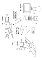
- FIG. 1 It is a schematic diagram which shows the structural example of the snow ice monitoring system which concerns on 1st Embodiment. It is a schematic diagram which shows the structural example of a monitoring apparatus. It is a photograph which shows an example of measurement data transmitted from a monitoring device. It is a photograph which shows an example of measurement data transmitted from a monitoring device. It is a photograph which shows an example of measurement data transmitted from a monitoring device. It is a block diagram showing an example of functional composition of an analysis device. It is a flow chart which shows an example of snow ice monitoring operation. It is a graph which shows an example of the radiative transfer model of snow.
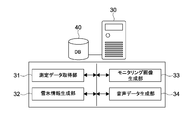
- FIG. 1 is a schematic view showing a configuration example of a snow and ice monitoring system according to a first embodiment of the present invention.
- the snow and ice monitoring system 100 includes a monitoring device 10, an analysis device 30, a database 40, and a display 50.
- the monitoring device 10 is embedded in the runway 1 of the airport (in the ground).
- the monitoring device 10 monitors the condition of the surface 2 of the runway 1 and transmits measurement data on the surface 2 of the runway 1 to the analysis device 30 as a result of the monitoring.
- the surface of the runway 1 corresponds to the surface to be measured.
- measurement data is transmitted via a network such as a wide area network (WAN) or a local area network (LAN).
- WAN wide area network
- LAN local area network
- the measurement data may be transmitted by wireless communication using a high frequency signal or the like.
- any communication form that enables wireless or wired communication may be constructed.
- the analysis device 30 receives the measurement data transmitted from the monitoring device 10.
- the analysis device 30 generates snow and ice information on snow (snow and ice) 3 deposited on the surface 2 of the runway 1 based on the features of the measurement data.
- ice and water are also described as being included in one of the types of snow (one in the state of snow).
- the thickness of snow includes the thickness of ice deposited on the surface 2 of the runway 1.
- the state in which the surface 2 of the runway 1 is wet with water is also regarded as the state in which water, which is one type of snow, is deposited.
- the snow 3 corresponds to a deposit deposited on the surface to be measured.
- snow and ice information corresponds to deposit information on deposits deposited on the surface to be measured.
- the snow and ice information includes, for example, the type of snow 3, the thickness (the amount of deposition), the density, the amount of water, the temperature, the distribution of deposition, and the like. Further, as the snow and ice information, an estimated value of the estimated value of the friction coefficient of the surface 2 of the runway 1 on which the snow 3 is deposited, and an evaluation value obtained by evaluating the state of the runway 1 on which the snow 3 is deposited according to a predetermined standard. As such evaluation value, for example, a runway condition code (RWYCC: Runway Condition Code) defined by the International Civil Aviation Organization (ICAO) is mentioned.
- RWYCC Runway Condition Code
- the evaluation value according to a predetermined standard can also be referred to as a converted amount to a numerical value according to the predetermined standard.
- another evaluation standard, an indicator, etc. may be adopted as a predetermined standard.
- any information about snow 3 such as the outside air temperature may be generated.
- arbitrary information on slipperiness such as arbitrary information that is an indicator of slipperiness, may be generated as deposit information.
- the monitoring result includes both information derived based on the snow and ice information and the snow and ice information itself.
- the analysis device 30 can generate and output at least one of text data, image data, and audio data as output data including snow and ice information.
- a monitoring image 60 including snow and ice information is generated and output to the display 50.
- the manager 5a in the control room or the like of the airport can determine the management guideline or the like of the runway 1 by confirming the monitoring image 60 displayed on the display 50a.
- the image data of the monitoring image 60 is transmitted to the aircraft 6 by radio or the like by the analysis device 30.
- the pilot 5b can determine whether or not to take off and land on the runway 1 by confirming the monitoring image 60 displayed on the display 50b in the cockpit.
- the image data of the monitoring image 60 may be transmitted to the display 50c that can be viewed by the operation manager 5c on the ground.
- the operation manager 5c on the ground can determine whether or not to take off and land on the runway 1 by confirming the monitoring image 60.
- the analysis device 30 may generate audio data including snow and ice information.
- a voice including snow and ice information is output through a speaker in a control room or the like on the ground, such as a control room or the like.
- the manager 5a, the pilot 5b, and the operation manager 5c on the ground can select an appropriate response according to the state of the surface 2 of the runway 1.
- text data including numerical data or the like that is snow and ice information may be generated and output to the display 50.
- text data including snow and ice information is displayed above or below the screen.
- the database 40 stores the measurement data transmitted from the monitoring device 10 and the history of snow / ice information generated by the analysis device 30. In addition, various data used for the snow and ice monitoring system 100 are stored.
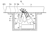
- FIG. 2 is a schematic view showing a configuration example of the monitoring device 10.
- the monitoring device 10 includes a housing 11, a transmission member 12, a transmission unit 13, a reception unit 14, and a control block 15.
- the housing unit 11 has an internal space S, and is embedded inside the runway 1 so that the top surface 11 a of the housing unit 11 has substantially the same height as the surface 2 of the runway 1. Further, an opening 16 is formed on the upper surface 11 a of the housing unit 11.
- the shape of the housing 11 (the shape of the internal space S) and the shape of the opening 16 are not limited.
- the case part 11 which has a cylindrical shape and in which the circular opening 16 is formed may be used.
- the casing 11 having a rectangular parallelepiped shape and having the rectangular opening 16 may be used.
- the transmitting member 12 is a member having transparency, and is fitted into the opening 16 formed in the upper surface 11 a of the housing 11 without a gap.
- the transmitting member 12 is provided at the opening 16 of the housing portion 11 so that the surface 12 a of the transmitting member 12 has the same height as the surface 2 of the runway 1. It becomes possible to acquire measurement data about surface 2 of runway 1 which is a measurement object surface by this.
- the surface 12 a of the transmitting member 12 is a surface included in the surface to be measured. However, the surface 12a does not have to be the same height as the surface 2 of the runway 1, and the heights may be different.
- the specific material of the transmissive member 12 is not limited, and a member having desired resistance such as tempered glass or reinforced plastic may be used appropriately. Moreover, having transparency includes both a transparent state and a semitransparent state with respect to the electromagnetic wave E1, and is not necessarily transparent / semitransparent to visible light.
- the transmission unit 13 is provided at a predetermined position in the internal space S of the housing 11 and has a transmitter 17 that emits an electromagnetic wave E1 as a measurement wave. In the present embodiment, it is possible to emit a plurality of electromagnetic waves E1 having different wavelengths.
- the transmitter 17 is, for example, a laser oscillator, and may itself be capable of emitting laser light of a plurality of different wavelengths. Alternatively, the transmitter unit 13 may be provided with a plurality of transmitters 17 capable of transmitting laser beams of different wavelengths.
- the wavelength band and the wavelength width of the laser beam are not limited, and a broad band laser beam, a narrow band laser beam or the like may be used as the measurement wave (electromagnetic wave E1) as appropriate.
- the configuration of the transmission unit 13 and the type of the electromagnetic wave E1 emitted as the measurement wave are not limited.
- the transmission unit 13 provided with another light source such as an LED or a lamp light source as the transmitter 17 may be used.
- an optical filter or the like capable of controlling the wavelength band, wavelength width, polarization direction, etc. of the electromagnetic wave E1 emitted to the transmitting member 12 may be installed in the transmission unit 13.
- the “electromagnetic wave” includes light of any wavelength range, such as infrared light, visible light, and ultraviolet light.
- the transmitting unit 13 is disposed to be inclined at a predetermined angle toward the lower surface of the transmitting member 12. That is, the transmitting unit 13 is configured such that the incident angle of the electromagnetic wave E1 incident on the lower surface of the transmitting member 12 is inclined.
- the installation angle ⁇ 1 of the transmission unit 13 is schematically illustrated using curved arrows.
- the specific value of the installation angle ⁇ 1 is not limited. For example, assuming that the angle at which the transmitting unit 13 is directed perpendicularly to the lower surface of the transmitting member 12 (the angle at which the electromagnetic wave E1 is vertically incident) is 0 °, the installation angle ⁇ 1 is in the range of 0 ° to 90 ° toward the receiving unit 14 side. It is set.
- the receiving unit 14 is provided at a position facing the transmitting unit 13 in the internal space S of the housing unit 11 at a predetermined distance t.
- the receiving unit 14 has a receiver 18 capable of detecting the intensity distribution of the electromagnetic wave E2 emitted from the lower surface of the transmitting member 12.
- the electromagnetic wave E ⁇ b> 1 emitted from the transmission unit 13 is reflected and scattered by the snow 3 deposited on the surface 12 a of the transmission member 12.
- the scattered wave (scattered light) reflected and scattered by the snow 3 is emitted from the lower surface of the transmitting member 12.
- the electromagnetic wave E2 emitted from the lower surface of the transmitting member 12 may be described as a scattered wave E2 using the same reference numeral.
- the receiver 18 is, for example, a two-dimensional optical sensor such as a CCD or a CMOS camera, and may be capable of detecting a two-dimensional intensity distribution of a plurality of scattered waves E2 different in wavelength by itself.
- a plurality of receivers 18 may be installed in the receiving unit 14, and one-dimensional or two-dimensional intensity distribution of a plurality of scattered waves E2 having different wavelengths as a whole may be detected.
- the configuration of the receiving unit 14 is not limited, and may be arbitrarily configured.
- an optical filter or the like having wavelength selectivity to transmit only the electromagnetic wave E2 to be detected may be installed in the receiving unit 14.
- the receiving unit 14 is disposed to be inclined at a predetermined angle toward the lower surface of the transmitting member 12.
- the installation angle ⁇ 2 of the reception unit 14 is schematically illustrated using curved arrows.
- the specific value of the distance t between the transmission unit 13 and the reception unit 14 and the installation angle ⁇ 2 of the reception unit 14 is not limited.
- the installation angle ⁇ 2 is set in the range of 0 ° to 90 ° toward the transmitting unit 13 side.
- the position and attitude of the transmission unit 13 and the position and attitude of the reception unit 14 may be arbitrarily controlled by a drive mechanism (not shown).
- the installation angle ⁇ 1 of the transmission unit 13, that is, the incident angle of the electromagnetic wave E1 to the transmission member 12 may be arbitrarily controlled.
- the distance t between the transmission unit 13 and the reception unit 14 and the installation angle ⁇ 2 of the reception unit 14 may be arbitrarily controlled. This makes it possible to obtain highly accurate measurement data.
- the drive mechanism can be realized by any actuator mechanism including, for example, a motor and a gear mechanism. Of course any other configuration may be employed. Of course, a configuration may be adopted in which the installation angle ⁇ 1 of the transmission unit 13, the distance t between the transmission unit 13 and the reception unit 14, and the installation angle ⁇ 2 of the reception unit 14 can be changed manually.
- the control block 15 includes a power supply unit (not shown), a control unit, a communication unit, and the like.
- the power supply unit supplies power to the transmission unit 13 and the reception unit 14.
- the specific configuration of the power supply unit is not limited.
- the control unit controls the operation of each of the transmission unit 13 and the reception unit 14 to execute emission of an electromagnetic wave E1 of a predetermined wavelength, and intensity detection of a two-dimensional distribution of a scattered wave E2 of a predetermined wavelength.
- the control unit transmits measurement data including the intensity signal (measurement signal) obtained by the receiver 18 of the receiving unit 14 to the analyzer 30 shown in FIG. 1 via the communication unit.
- the control unit has, for example, a hardware configuration necessary for a computer such as a CPU and a memory (RAM, ROM).
- a device such as a PLD (Programmable Logic Device) such as an FPGA (Field Programmable Gate Array) or another application specific integrated circuit (ASIC) may be used.
- a communication unit arbitrary configurations, such as arbitrary wireless modules, may be used, for example.
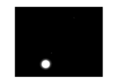
- FIG. 3 to 5 are photographs showing an example of measurement data transmitted from the monitoring device 10 to the analysis device 30.
- FIG. In the present embodiment two-dimensional intensity distributions of scattered waves E2 of different wavelengths are transmitted as measurement data.
- an image signal including intensity information (luminance information) of each pixel generated by the receiver 18 is transmitted as measurement data.
- the image signal generated by the receiver 18 corresponds to measurement image data obtained by irradiating a measurement wave toward the surface to be measured.
- the image signal is referred to as measurement image data.
- FIGS. 3 to 5 are diagrams showing images generated based on measurement image data obtained when electromagnetic waves E1 having different wavelengths are irradiated in a state where snow 3 is deposited on the transmitting member 12. .
- this image itself may be described as measurement image data.
- the electromagnetic wave E1 emitted toward the transmitting member 12 is reflected and scattered by the snow 3 and emitted from the transmitting member 12 toward the receiving unit 14 as a scattered wave E2.
- An image signal of the scattered wave E2 reflected and scattered by the snow 3 is generated as measurement image data.
- three types of images (image signals) shown in FIGS. 3 to 5 are generated by emitting electromagnetic waves E1 having different first to third wavelengths ⁇ 1 to ⁇ 3.
- These images are two-dimensional light scattering images of the scattered wave E2 obtained by emission of the electromagnetic wave E1. That is, it is a two-dimensional light scattering image of each of the scattered waves E2 of the first to third wavelengths ⁇ 1 to ⁇ 3.
- These three types of two-dimensional light scattering images (image signals) are transmitted to the analysis device 30 as measurement image data.
- the three types of measurement image data correspond to a plurality of measurement data corresponding to a plurality of electromagnetic waves obtained by irradiating a plurality of electromagnetic waves having different wavelengths toward the surface to be measured.
- the plurality of measurement data are not limited to three types of measurement image data, and two or more arbitrary numbers of measurement image data may be generated.
- only one type of measurement image data obtained by being irradiated with an electromagnetic wave of one type of wavelength may be transmitted to the analysis device 30, and snow and ice information may be generated.
- FIG. 6 is a block diagram showing a functional configuration example of the analysis device 30.
- the analysis device 30 has hardware necessary for the configuration of the computer, such as a CPU, a ROM, a RAM, and an HDD.
- a PC Personal Computer
- any other computer may be used.
- the CPU loads a program according to the present technology stored in the ROM or the HDD into the RAM and executes the program to obtain the measurement data acquisition unit 31, the snow and ice information generation unit 32, and the monitoring image generation unit which are functional blocks shown in FIG. 33 and an audio data generation unit 34 are realized. And the information processing method concerning this art is performed by these functional blocks. Dedicated hardware may be used as appropriate to realize each functional block.
- the analysis device 30 corresponds to an information processing device.
- the program is installed in the analysis device 30 via, for example, various recording media. Alternatively, the program may be installed via the Internet or the like.
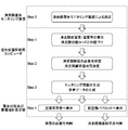
- FIG. 7 is a flowchart showing an example of the snow and ice monitoring operation.
- the “runway snow and ice monitoring device” in the figure corresponds to the monitoring device 10, and the “snow and ice condition analysis computer” corresponds to the analysis device 30.
- the “snow and ice condition and control pointer display” in the figure corresponds to the display 50 shown in FIG.
- measurement is first performed by the monitoring device 10 as Step 0. Specifically, measurement image data of snow 3 deposited on the surface 12 a of the transmission member 12 is generated. In this embodiment, three types of measurement image data obtained by emitting the electromagnetic waves E1 of the first to third wavelengths ⁇ 1 to ⁇ 3 as illustrated in FIGS. Will be sent.
- the transmitted measurement image data is acquired by the measurement data acquisition unit 31 shown in FIG. In the present embodiment, the measurement data acquisition unit 31 functions as an acquisition unit.
- step 1 snow and ice information on snow deposited on the transmission member 12 (snow deposited on the surface 2 of the runway 1) is generated by the analysis device 30 based on the features of the measurement image data.
- the type of snow 3 (snow quality) and the thickness of the snow 3 (snow thickness) are first calculated by the snow and ice information generation unit 32 shown in FIG. 6.
- snow quality for example, “frost (FROST)” "dry snow (DRY SNOW)” “slash (SLUSH)” “wet snow (WET SNOW)” “compressed snow” “ice (ICE)” " It includes arbitrary snow conditions such as new snow (FRESH) and “smooth snow (GRANULAR)”.
- snow and ice information regarding snow information such as “DRY” which is a state without snow, or information such as “wet (DRY)” and “STANDING WATER” may be generated. These pieces of information may be treated in the same manner as the snow quality information.
- snow thickness for example, information in mm is generated.
- snow thickness information may be generated in units of arbitrary thickness such as 5 mm, 10 mm, 50 mm, and the like.
- a method of calculating the snow quality and the snow thickness will be described based on the characteristics of the image measurement data exemplified in FIGS. 3 to 5.
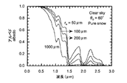
- FIG. 8 is a graph showing an example of a snowfall radiative transfer model.
- the albedo ratio of reflected light to incident light
- re 50 ⁇ m in the figure corresponds to fresh snow, and 1000 ⁇ m corresponds to rough snow.
- the amount of light reflected / scattered largely changes with respect to snow quality and wavelength, and snow thickness and snow quality can be calculated from the relationship of reflection / scattering intensity to light wavelength.
- the quality of the snow (including ice and water) 3 present on the transmitting member 12 by irradiating the electromagnetic waves E1 of a plurality of different wavelengths and detecting the two-dimensional intensity distribution of the scattered waves E2 for each wavelength It is possible to separate and determine the thickness accurately. As a result, it becomes possible to monitor the state regarding snow 3 in detail.
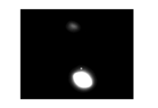
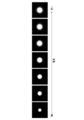
- FIG. 9 is a photograph showing measurement image data in the case where the electromagnetic wave E1 of the same wavelength is irradiated to the snow 3 different in thickness.
- the amount of the scattered wave E2 reflected and scattered by the snow 3 increases. Accordingly, the amount of the scattered wave E2 emitted from the transmitting member 12 toward the receiving unit 14 increases, and the maximum diameter (maximum diameter of the light receiving area) of the scattered wave E2 included in the measurement image data increases. That is, since the maximum diameter of the scattered wave E2 changes according to the snow thickness, it is possible to monitor the snow thickness with high accuracy based on the feature of the measurement image data.
- the amount of the scattered wave E2 reflected and scattered by the snow 3 changes in accordance with the change in the water content (water content) and particle size of the snow 3 deposited on the transmitting member 12. Therefore, it is possible to monitor not only the snow thickness but also the water content and particle size with high accuracy based on the characteristics of the measurement image data. Based on the water content and particle size, it is possible to identify snow quality such as the aforementioned "dry snow (DRY SNOW)".
- an electromagnetic wave of a wavelength where the amount of light reflected / scattered largely changes according to a change of snow thickness and an electromagnetic wave of a wavelength where an amount of light reflected / scattered largely changes according to a change of water content
- Three types of electromagnetic waves E1 of an electromagnetic wave of a wavelength where the amount of light reflected and scattered largely changes according to a change in particle diameter are used as measurement waves.
- the threshold value regarding a luminance value may be set in each pixel of the receiver 18. An image signal may be generated with zero luminance for luminance values below the threshold. This makes it possible to improve the accuracy of monitoring based on the maximum diameter of the scattered wave E2.
- the snow thickness, the water content, and the particle size correspond to a plurality of different types of deposit information corresponding to a plurality of measurement image data.
- the specific wavelength values for monitoring each of the snow thickness, the water content, and the particle diameter with high accuracy can be appropriately set by calibration or the like.
- Information calculated as snow and ice information is not limited to snow thickness, water content, and particle size, and other parameters such as density, temperature, uniformity of particles, etc. may be calculated.
- the wavelength of the electromagnetic wave E1 it is possible to calculate an arbitrary parameter that changes the absorption characteristic and the scattering characteristic of the snow 3 based on the feature of the measurement image data.
- the characteristics of the measurement image data include not only the maximum diameter of the scattered wave E2, but also the position, area (area of the light receiving area), shape (flatness, roundness, etc.) of the scattered wave E2, and inclination of intensity in the light receiving area (Slope of luminance), the intensity of the central portion of the light receiving area, the average of the intensity, or any other characteristic regarding the two-dimensional distribution such as the intensity (luminance) may be adopted. This makes it possible to monitor snow thickness, water content, and particle size with high accuracy.
- the snow and ice information generation unit 32 generates snow and ice information according to a predetermined machine learning algorithm.
- machine learning algorithm using DNN such as RNN (Recurrent Neural Network), CNN (Convolutional Neural Network), MLP (Multilayer Perceptron), etc. Is used.
- DNN Deep Neural Network
- CNN Convolutional Neural Network
- MLP Multilayer Perceptron
- any machine learning algorithm that executes supervised learning method, unsupervised learning method, semi-supervised learning method, reinforcement learning method and the like may be used.
- an AI Artificial Intelligence
- deep learning deep learning
- feature amounts defined by an operator or the like for performing learning by a machine learning algorithm, and feature amounts extracted by the algorithm are also included in the features of the measurement image data according to the present embodiment.
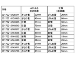
- FIG. 10 is a table showing the identification results for actual snow cover. As for snow quality and snow thickness, it is understood that the identification result by AI is very close to the measured value. It is also possible to obtain a more accurate identification result by appropriately constructing a machine learning algorithm.
- Step 1 linking the calculated snow quality and thickness with the runway status code is executed as Step 1. That is, a runway state code is generated as snow and ice information.
- the method of linking these pieces of information is not limited.
- the snow quality and thickness necessary to derive the runway status code may be directly calculated, or the snow quality and thickness calculated in step 1 may be appropriately calculated to derive the runway status code. It may be converted.
- other parameters such as the outside temperature may be referred to as appropriate to derive the runway status code.
- step 2 the analysis device 30 determines the need for snow removal on the runway 1. Further, it is determined whether or not the runway 1 is to be taken off and land. These processes are typically performed based on the snow quality and thickness and the runway status code calculated in step 1.
- step 2 is also executed by the snow and ice information generation unit 32. That is, in the present embodiment, information indicating whether there is a need for a snow removal operation and whether takeoff and landing are possible is generated as snow and ice information on snow 3 deposited on the transparent member 12 (snow deposited on runway 1) 3 . Thus, information on the management guidelines, judgment information on operation, etc. may be generated as snow and ice information.
- Information indicating whether or not the snow removal work is necessary directly based on the measurement image data acquired in step 0, not the snow quality and snow thickness generated in step 1, but the runway status code, And information indicating whether take-off and landing are possible may be generated.
- a predetermined machine learning algorithm may be used.
- step 3 the analysis device 30 generates output data including the snow and ice information generated in steps 1 and 2.
- the monitoring image generation unit 33 generates a monitoring image 60 including snow and ice information.
- the audio data generation unit 34 generates audio data including snow and ice information.
- the monitoring image generation unit 33 and the audio data generation unit 34 function as an output unit.
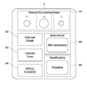
- FIG. 11 is a schematic view showing an example of the monitoring image 60.
- the monitoring image 60 includes a measurement image data display unit 61, a snow quality (type of snow) display unit 62, a snow thickness display unit 63, a runway status code display unit 64, a snow removal necessity display unit 65, takeoff and landing An availability display unit 66 is provided.
- the measurement image data display unit 61 displays the measurement image data transmitted from the monitoring device 10. In the present embodiment, three types of two-dimensional light scattering images illustrated in FIGS. 3 to 5 are displayed.
- the snow quality display unit 62 displays the snow quality calculated in step 1.
- the snow thickness display section 63 displays the snow thickness calculated in step 1.
- the runway status code display unit 64 displays the runway status code generated in step 1.
- the snow removal necessity display section 65 the presence or absence of the necessity of the snow removal work generated as snow and ice information in step 2 is displayed.
- the takeoff / landing availability display unit 66 displays information indicating whether takeoff or landing, which is generated as snow and ice information in step 2, is possible.
- the monitoring image 60 is output and displayed on the display 50a that can be viewed by the manager 5a of the airport (runway 1). Moreover, the monitoring image 60 is displayed on the display 50b which can view the pilot 5b of an aircraft. Of course, the monitoring image 60 may be displayed on the display 50c that can be viewed by the operation manager 5c on the ground.
- the manager 5a, the pilot 5b, and the operation manager 5c on the ground can easily grasp the state of the surface 2 of the runway 1, and the management guidelines and the like are easily made. It is possible to decide on For example, the manager 5a can easily determine the necessity of snow removal, and can easily manage the runway 1 based on the runway status code. Further, the pilot 5b of the aircraft can easily determine whether or not the runway 1 can be taken off and land without directly confirming the surface 2 of the runway 1. Of course, it becomes possible to perform operations etc. based on the runway status code. In addition, the operation manager 5c on the ground can easily determine whether or not to take off and land on the runway 1, and, for example, it is possible to comprehensively determine an appropriate response together with the result of direct confirmation on the site. It becomes possible.
- step 4 audio data including snow and ice information may be generated.
- a voice including snow and ice information is output through a speaker in a control room or the like on the ground, such as a control room or the like.
- the manager 5a, the pilot 5b, and the operation manager 5c on the ground can select an appropriate response according to the state of the surface 2 of the runway 1.
- the configuration of the monitoring image 60 is not limited, and an arbitrary image (GUI) may be generated and displayed. Also, the snow and ice information included in the monitoring image 60 is not limited, and arbitrary snow and ice information may be displayed.
- the present invention is not limited to the case where the same monitoring image 60 is generated, and a monitoring image for management to be provided to the administrator 5a, a monitoring image for pilot to be provided to the pilot 5b, and a ground operation manager 5c.
- the operation manager monitoring images to be provided to each may be separately configured.
- the monitoring image 60 may be freely customizable by the manager 5a, the pilot 5b, and the operation manager 5c on the ground. That is, snow and ice information to be confirmed may be appropriately selected.
- the contents (letters, symbols, images) of the snow ice information to be displayed, its arrangement, size, color arrangement, etc. may be manually or automatically changeable according to the environment or situation.
- the audio data the audio content may be changed as appropriate based on the environment, the situation, the generated snow and ice information and the like. For example, a warning or information to be transmitted may be appropriately determined, and audio data to be output may be appropriately generated.
- a plurality of monitoring devices 10 are often installed at a plurality of locations of the runway 1.
- a monitoring image 60 illustrated in FIG. 11 may be generated. This makes it possible to grasp the surface condition at each point of the runway 1.
- snow and ice information generated based on measurement data measured by each monitoring device 10 may be integrated, and a monitoring image 60 including the integrated snow and ice information may be generated.
- the surface condition (snow and ice information) at each point may be integrated to generate and display snow quality, snow thickness, runway condition code, necessity of snow removal, and availability of takeoff and landing. Thereby, it is possible to grasp the entire state of the runway 1.
- the method of integrating a plurality of pieces of snow and ice information is not limited, and information obtained by averaging snow quality and thickness of each point is displayed.
- weighting may be performed depending on the point at which the monitoring device 10 is installed. For example, the measurement data of the monitoring device 10 installed at the center of the runway 1 and the snow and ice information generated therefrom are weighted heavily. On the other hand, the measurement data etc. of the monitoring device 10 installed at the position of the end of the runway 1 has a small weighting. Such processing is also possible.
- snow and ice information may be generated and displayed for each area of runway 1.
- snow ice information is generated based on the measurement data transmitted from the monitoring device 10 and displayed in the monitoring image 60.
- measurement data and snow and ice information are integrated and displayed in the monitoring image 60.
- the information with the worst state may be selected and displayed in the monitoring image 60.
- the information with the worst state may be selected and displayed in the monitoring image 60. For example, it is assumed that snow ice information is generated for one point that snow removal is necessary and take-off and landing are impossible. In this case, even if snow and ice information indicating that there is no need for snow removal and take-off and landing is generated for multiple other points, snow and ice information indicating that take-off and landing is not possible is displayed. Be done. Such processing is also possible.
- prediction information for predicting the state of the surface 2 of the runway 1, which is the surface to be measured based on at least one of measurement data (measurement image data) acquired from the monitoring device 10 and generated snow and ice information It is possible to generate. For example, it is possible to generate prediction information for predicting how snow quality, snow thickness, runway status code, necessity of snow removal work, and whether or not takeoff and landing are transitioning in the future.
- the prediction information is generated based on, for example, measurement data stored in the database 40 shown in FIG. 1, historical information such as snow and ice information, and the like, a predetermined prediction model, prediction data, and the like. For example, it is possible to generate prediction information including snow quality and thickness such as after 10 minutes, 30 minutes, 60 minutes, etc. based on weather information etc. acquired via a weather radar etc. installed at an airport It is. Of course, any machine learning algorithm may be used to generate prediction information. By generating prediction information, it is possible to accurately determine airport management guidelines, operation plans and the like.
- Predicted measurement data on the surface 2 of the runway 1, which is the surface to be measured may be generated based on the characteristics of the measurement data acquired from the monitoring device 10. For example, predictive measurement data is generated to predict how the two-dimensional light scattering image changes as illustrated in FIGS. 3-5. And prediction information may be generated based on this prediction measurement data.
- snow and ice information is produced
- the surface 2 of runway 1 It becomes possible to grasp the state of the very accurately.
- the monitoring device 10 is embedded inside the runway 1, it is possible to avoid an obstacle to the aircraft. In addition, it is possible to monitor the detailed condition of snow depth and quality on the entire runway while preventing damage etc. due to the collision of foreign matter from the outside.
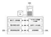
- FIG. 12 is a block diagram showing a functional configuration example of the analysis device 230 according to the present embodiment.
- the analyzer 230 has a measurement wavelength determination unit 235 and an external control unit 236 as functional blocks.
- the measurement wavelength determination unit 235 determines the characteristics of the measurement wave emitted from the transmitter 17 of the monitoring device 10 based on at least one of the measurement data (measurement image data) acquired from the monitoring device 10 and the generated snow and ice information. It is possible to make a decision.
- the measurement wavelength determination unit 235 corresponds to a setting unit.
- the wavelength to be used for measurement is selected from the plurality of wavelengths.
- the electromagnetic waves E1 of the first to third wavelengths ⁇ 1 to ⁇ 3 having different absorption, scattering, and reflection characteristics are emitted, the first wavelength ⁇ 1, the second wavelength ⁇ 2, and the third wavelength It is possible to select each of ⁇ 3 appropriately from a plurality of wavelengths.
- the first wavelength ⁇ 1, the second wavelength ⁇ 2, and the third wavelength ⁇ 3 may be within the wavelength range. Each is determined appropriately.
- a wavelength necessary for measurement may be selected from the first wavelength ⁇ 1, the second wavelength ⁇ 2, and the third wavelength ⁇ 3 in accordance with the measured snow quality and thickness.
- the wavelength of the electromagnetic wave E1 is appropriately selected from the first wavelength ⁇ 1, the second wavelength ⁇ 2, and the third wavelength ⁇ 3 so that desired snow / ice information can be obtained according to the state of the snow 3 .
- Such processing is also possible.
- the characteristics of the measurement wave emitted from the transmitter 17 such as the wavelength of the electromagnetic wave E1 can be set by the operation of the administrator 5a or a specialized operator or the like, which is input via a predetermined computer such as a PC. It is also good. That is, the characteristics of the measurement wave may be changeable manually.
- a specific example of setting of the wavelength of the electromagnetic wave E1 will be described.
- a wavelength suitable for snow thickness observation is selected in advance (a visible wavelength more likely to flow in the snow layer, etc.).
- a wavelength suitable for measuring the water content water content ratio
- the wavelength of the electromagnetic wave E1 based on the result of the snow thickness. For example, when snow thickness is first measured at a certain wavelength, it is determined that only thin snow thickness is accumulated. In this case, since it is necessary to measure the snow quality of the surface layer rather than the thickness of the snow, it shifts to the measurement by the wavelength such as near infrared which is effective for the particle size determination. When it is judged that the snow thickness is thick to some extent, emphasis is placed on snow thickness measurement by selecting a visible wavelength or the like that can penetrate the snow layer rather than the near infrared wavelength.
- the wavelength of the electromagnetic wave E1 based on the result of the moisture content. For example, when the moisture content is first measured at a certain wavelength, it is assumed that the moisture content is determined to be high to some extent. In this case, since an error may occur due to the moisture content in optical observation of the snow quality, a wavelength effective for moisture content measurement and a wavelength effective for snow quality measurement are simultaneously selected to compensate for the error. If it is determined that the moisture content is at a level not affected by the error, only the wavelength effective for snow quality observation is selected and the snow quality is mainly measured.
- the characteristic of the measurement wave is not limited to the wavelength of the electromagnetic wave E1, and any characteristic such as the intensity of the electromagnetic wave E1, the polarization state, and the pulse interval may be determined. Also, any machine learning algorithm may be used to set the characteristics of the measurement wave.
- the intensity of the electromagnetic wave E1 and the gain of the receiver 18 may be manually or automatically selectable based on measurement data, snow and ice information, and the like. For example, when a range over (saturation) portion exists in the measurement data, the intensity (brightness) of the electromagnetic wave E1 is lowered and the gain of the receiver 18 is decreased. If the entire measurement data is smaller than a predetermined threshold, the intensity (luminance) of the electromagnetic wave E1 is increased and the gain of the receiver 18 is decreased. As described above, by appropriately changing the strength and the gain from the tendency of the measurement data, the optimum measurement can be performed.
- the intensity of the electromagnetic wave E1 or the gain of the receiver 18 may be changed based on external weather information or the like. For example, if the external environmental light is strong and the value of the measurement data is large, the intensity (luminance) of the electromagnetic wave E1 is increased and the gain of the receiver 18 is decreased to improve the S / N of the data. . Such processing is also possible.
- the external control unit 236 generates control information for controlling an external device based on at least one of the measurement data (measurement image data) acquired from the monitoring device 10 and the generated snow and ice information. For example, the external control unit 236 can transmit a signal for controlling an external device according to the measurement data and the snow and ice information processed by the environment or situation and analysis device 230.
- the external control unit 236 corresponds to a control information generation unit.
- FIG. 13 is a schematic view showing a configuration example of a monitoring device according to another embodiment.
- the monitoring device 310 includes a housing 311, a transmitting member 312, a transmitting unit 313, a plurality of receiving units 314, and a control block 315.
- the plurality of receiving units 314 are arranged in five rows from the transmitting unit 313 side. By installing a plurality of receiving units 314 in this manner, it becomes possible to measure the snow quality and thickness for a wide range of snow 3 and monitor the state of the surface 2 of the runway 1 with high accuracy. It becomes possible.
- the scope to which the technology can be applied is not limited to snow and ice monitoring of airport runways. It is applicable to monitoring the surface condition of other structures such as roads, bridges and buildings. Further, the present invention is not limited to take-off and landing of an aircraft, and may be applied to determination regarding the traveling of another moving object such as a vehicle. Also, with regard to deposits, it is possible to apply the present technology to any deposits such as snow, ice, water, mud, volcanic ash and the like. That is, the present technology is applicable to various fields.
- a monitoring device on the road surface, it is possible to display the surface condition of snow, sand, etc. on the road surface to the road administrator and utilize it for road management. For example, it becomes possible to easily carry out judgment of necessity of blockade of a road, selection of a detour etc. Further, by displaying a monitoring image or the like on a display panel of a general automobile, it is possible to notify the driver of the condition of the road surface in real time through, for example, a network or the like, and prevent accidents and improve traffic efficiency. Further, not only real-time surface condition but also road surface condition prediction display combined with prediction model of future snowfall condition etc. can be applied, and traffic efficiency can be further improved.
- information on the layer structure of the deposit may be generated. For example, changes in the quality of snow or volcanic ash in the thickness direction, the state of each layer to be stacked, or the like may be generated as deposit information.
- a plurality of measurement data corresponding to a plurality of electromagnetic waves are acquired by irradiating a plurality of electromagnetic waves having different wavelengths toward the surface to be measured.
- the invention is not limited thereto, and a plurality of electromagnetic waves having different wavelength bands or wavelength widths may be irradiated toward the surface to be measured, and a plurality of measurement data corresponding to the plurality of electromagnetic waves may be acquired.
- a broad band laser beam, a narrow band laser beam or the like is irradiated as a plurality of measurement waves (electromagnetic waves E1), and a plurality of measurement data corresponding to these laser beams are generated. Then, a plurality of deposit information corresponding to a plurality of measurement data may be generated.
- deposit information is generated based on one type of measurement data obtained by irradiation with one type of electromagnetic wave, such as an electromagnetic wave of a predetermined wavelength (single wavelength), an electromagnetic wave of a predetermined wavelength band, an electromagnetic wave of a predetermined wavelength width. It is also possible.
- the monitoring apparatus may have a configuration including a transmission unit capable of irradiating an electromagnetic wave in a linear polarization state and a reception unit capable of detecting an electromagnetic wave in a linear polarization state in a specific direction.
- the polarization direction of the emitted electromagnetic wave and the detectable polarization direction of the electromagnetic wave are set so as to have a substantially orthogonal Nicol relationship that is substantially orthogonal to each other.
- the monitoring device may be configured to be portable. This makes it possible, for example, to carry and install the monitoring device on a snowy mountain or a land near a volcano. And based on the measurement data transmitted from a monitoring apparatus, it becomes possible to monitor the state of the desired surface with high precision. For example, information such as the possibility of occurrence of an avalanche or the possibility of an eruption can be generated as deposit information or its prediction information.
- generates measurement data by irradiating electromagnetic waves was mentioned.
- the present invention is not limited to this, and another sensor device or the like that can measure the outside air temperature or the like as measurement data may be used as the monitoring device.
- the temperature which is measurement data may be used as it is as snow and ice information.
- a device that outputs text data as measurement data may be used as the monitoring device.
- a configuration may be employed in which text data is generated based on measurement data obtained by any measurement method, and the text data is output as measurement text data.
- arbitrary data may be output as measurement data. Similar to the plurality of measurement image data described above, a plurality of measurement text data may be output, and a plurality of deposit information corresponding to the plurality of measurement text data may be generated.
- an analysis device has been exemplified as an embodiment of the information processing device according to the present technology.
- the information processing method according to the present technology may be executed by a cloud server without being limited to this.
- the information processing method according to the present technology may be executed by interlocking a plurality of computers that can communicate with each other.
- the information processing method according to the present technology by the computer system and the execution of the program are both performed when processing such as generation of deposit information is executed by a single computer and when each processing is executed by a different computer. Including. Also, execution of each process by a predetermined computer includes performing a part or all of the process on another computer and acquiring the result.
- the information processing method and program according to the present technology can be applied to the configuration of cloud computing in which one function is shared and processed by a plurality of devices via a network.
Abstract
【課題】測定対象となる表面の状態を高精度にモニタリングして、そのモニタリング結果を有効に利用することを可能とする情報処理装置、情報処理方法、プログラム、及びモニタリングシステムを提供すること。 【解決手段】上記目的を達成するため、本発明の一形態に係る情報処理装置は、取得部と、生成部とを具備する。前記取得部は、測定対象表面に関する測定データを取得する。前記生成部は、前記取得された測定データの特徴に基づいて、前記測定対象表面に堆積する堆積物に関する堆積物情報を生成する。
Description
本発明は、路面や構造物の表面の状態のモニタリングに適用可能な情報処理装置、情報処理方法、プログラム、及びモニタリングシステムに関する。
道路面や滑走路面(以降「路面」と言う)の着雪・着氷状態をモニタリングすることは、安全管理上、重要である。当該モニタリングのために、路面上の外部からレーザや音波等を照射して距離を測定することで積雪の深さを計測する技術が知られている。また外部から電磁波を照射して積雪等の状態を計測する技術も知られている。
しかしながら、上記の技術を実施する場合に、路面上や路面傍にモニタリング装置を設置すると、交通障害の原因となってしまう可能性が高い。また空港の滑走路やその周囲の上方にモニタリング装置を設置することは、航空機の離着陸の安全性に影響を与えるため、設置に関して大きな制限がある。
特許文献1には、路面や構造物の内部に埋め込むことが可能であり、路面や構造物の表面に局所的に付着した雪等(雪、氷、水、火山灰、砂等)の有無を判定できるとともに、詳細な積雪の深さや質に関する状態をモニタリングすることが可能な雪氷モニタリング装置が開示されている。
この雪氷モニタリング装置を滑走路の内部に埋め込むことで、航空機の障害となることを回避することが可能である。また外部からの異物の衝突等による破損等を防止しつつ、滑走路全体の詳細な積雪の深さや質に関する状態をモニタリングすることが可能となる(特許文献1の明細書段落[0011][0016])。
このように路面や構造物の表面の状態を高精度にモニタリングすることは非常に重要であり、そのモニタリング結果を有効に利用することを可能とする技術が求められている。
以上のような事情に鑑み、本発明の目的は、測定対象となる表面の状態を高精度にモニタリングして、そのモニタリング結果を有効に利用することを可能とする情報処理装置、情報処理方法、プログラム、及びモニタリングシステムを提供することにある。
上記目的を達成するため、本発明の一形態に係る情報処理装置は、取得部と、生成部とを具備する。
前記取得部は、測定対象表面に関する測定データを取得する。
前記生成部は、前記取得された測定データの特徴に基づいて、前記測定対象表面に堆積する堆積物に関する堆積物情報を生成する。
前記取得部は、測定対象表面に関する測定データを取得する。
前記生成部は、前記取得された測定データの特徴に基づいて、前記測定対象表面に堆積する堆積物に関する堆積物情報を生成する。
この情報処理装置では、測定対象表面の測定データの特徴に基づいて、堆積物情報が生成される。これにより、測定対象表面の状態を高精度にモニタリングして、そのモニタリング結果を有効に利用することが可能となる。
前記堆積物情報は、前記堆積物の種類、厚み、密度、粒径、水分量、温度、堆積分布、摩擦係数、滑りやすさの指標となる情報、及び所定の基準に従った評価値の少なくとも1つを含んでもよい。
これにより高精度のモニタリング及びモニタリング結果の有効利用が可能となる。
これにより高精度のモニタリング及びモニタリング結果の有効利用が可能となる。
前記所定の基準に従った評価値は、国際民間航空機関が定める滑走路状態コードを含んでもよい。
これにより滑走路状態コードに基づいた滑走路の管理等が容易に実現される。
これにより滑走路状態コードに基づいた滑走路の管理等が容易に実現される。
前記生成部は、前記取得された測定データ、及び前記生成された堆積物情報の少なくとも一方に基づいて、前記測定対象表面の状態を予測する予測情報を生成してもよい。
これにより高精度のモニタリング及びモニタリング結果の有効利用が可能となる。
これにより高精度のモニタリング及びモニタリング結果の有効利用が可能となる。
前記取得部は、前記取得した測定データの特徴に基づいて、前記測定対象表面に関する予測測定データを生成してもよい。この場合、前記生成部は、前記生成された予測測定データに基づいて、前記予測情報を生成してもよい。
これにより高精度のモニタリング及びモニタリング結果の有効利用が可能となる。
これにより高精度のモニタリング及びモニタリング結果の有効利用が可能となる。
前記情報処理装置は、さらに、前記生成された堆積物情報を含む出力データを出力する出力部を具備してもよい。
これにより測定対象表面の状態を容易に把握することが可能となり、管理指針等を容易に決定することが可能となる。
これにより測定対象表面の状態を容易に把握することが可能となり、管理指針等を容易に決定することが可能となる。
前記出力データは、前記堆積物情報を含むテキストデータ、画像データ、及び音声データの少なくとも1つを含んでもよい。
これにより測定対象表面の状態を容易に把握することが可能となり、管理指針等を容易に決定することが可能となる。
これにより測定対象表面の状態を容易に把握することが可能となり、管理指針等を容易に決定することが可能となる。
前記測定対象表面に堆積する堆積物は、滑走路表面に堆積する雪を含んでもよい。
これにより滑走路表面の状態を高精度にモニタリングして、そのモニタリング結果を有効に利用することが可能となる。なお本開示では、氷、及び水は、雪の種類の1つ(雪の状態の1つ)に含まれ、従って「雪」は「雪氷」を含む。
これにより滑走路表面の状態を高精度にモニタリングして、そのモニタリング結果を有効に利用することが可能となる。なお本開示では、氷、及び水は、雪の種類の1つ(雪の状態の1つ)に含まれ、従って「雪」は「雪氷」を含む。
前記出力部は、前記滑走路表面に堆積する雪の厚み、種類、密度、粒径、水分量、温度、堆積分布、摩擦係数、滑りやすさに関する情報、国際民間航空機関が定める滑走路状態コード、除雪作業の必要性の有無、及び離着陸が可能か否かを示す情報の少なくとも1つを含む前記出力データを出力してもよい。
これにより滑走路表面の状態を容易に把握することが可能となり、滑走路の管理指針等を容易に決定することが可能となる。
これにより滑走路表面の状態を容易に把握することが可能となり、滑走路の管理指針等を容易に決定することが可能となる。
前記生成部は、所定の機械学習アルゴリズムに従って、前記堆積物情報を生成してもよい。もちろん所定のディープラーニング(深層学習)アルゴリズムや、所定のAI(人工知能)アルゴリズムが用いられてもよい。
これにより測定対象表面の状態を高精度にモニタリングして、そのモニタリング結果を有効に利用することが可能となる。
これにより測定対象表面の状態を高精度にモニタリングして、そのモニタリング結果を有効に利用することが可能となる。
前記測定データは、前記測定対象表面に測定波を照射することで得られる測定テキストデータ、又は測定画像データを含んでもよい。
これにより測定対象表面の状態を高精度にモニタリングして、そのモニタリング結果を有効に利用することが可能となる。
これにより測定対象表面の状態を高精度にモニタリングして、そのモニタリング結果を有効に利用することが可能となる。
前記測定データは、前記測定対象表面に向けて所定波長の電磁波、所定波長帯域の電磁波、及び所定波長幅の電磁波の少なくとも1つを照射することで得られる測定テキストデータ、又は測定画像データを含んでもよい。
これにより測定対象表面の状態を高精度にモニタリングして、そのモニタリング結果を有効に利用することが可能となる。
これにより測定対象表面の状態を高精度にモニタリングして、そのモニタリング結果を有効に利用することが可能となる。
前記測定データは、前記測定対象表面に向けて波長の異なる複数の電磁波を照射することで得られる、前記複数の電磁波に対応する複数の測定データを含んでもよい。この場合、前記生成部は、前記複数の測定データに基づいて、前記堆積物情報を生成してもよい。
これにより測定対象表面の状態を高精度にモニタリングして、そのモニタリング結果を有効に利用することが可能となる。
これにより測定対象表面の状態を高精度にモニタリングして、そのモニタリング結果を有効に利用することが可能となる。
前記測定データは、前記測定対象表面に向けて波長帯域又は波長幅の異なる複数の電磁波を照射することで得られる、前記複数の電磁波に対応する複数の測定データを含んでもよい。この場合、前記生成部は、前記複数の測定データに基づいて、前記堆積物情報を生成してもよい。
これにより測定対象表面の状態を高精度にモニタリングして、そのモニタリング結果を有効に利用することが可能となる。
これにより測定対象表面の状態を高精度にモニタリングして、そのモニタリング結果を有効に利用することが可能となる。
前記生成部は、前記複数の測定データに対応する種類の異なる複数の堆積物情報を生成してもよい。
これにより測定対象表面の状態を高精度にモニタリングして、そのモニタリング結果を有効に利用することが可能となる。
これにより測定対象表面の状態を高精度にモニタリングして、そのモニタリング結果を有効に利用することが可能となる。
前記種類の異なる複数の堆積物情報は、前記堆積物の厚み、水分量、及び粒径を含んでもよい。
これにより測定対象表面の状態を高精度にモニタリングして、そのモニタリング結果を有効に利用することが可能となる。
これにより測定対象表面の状態を高精度にモニタリングして、そのモニタリング結果を有効に利用することが可能となる。
前記情報処理装置は、さらに、前記取得された測定データ、及び前記生成された堆積物情報の少なくとも一方に基づいて、前記測定波の特性を設定する設定部を具備してもよい。
これにより測定対象表面の状態を高精度にモニタリングして、そのモニタリング結果を有効に利用することが可能となる。
これにより測定対象表面の状態を高精度にモニタリングして、そのモニタリング結果を有効に利用することが可能となる。
前記情報処理装置は、さらに、前記取得された測定データ、及び前記生成された堆積物情報の少なくとも一方に基づいて、外部の装置を制御するための制御情報を生成する制御情報生成部を具備してもよい。
本発明の一形態に係る情報処理方法は、コンピュータシステムにより実行される情報処理方法であって、測定対象表面に関する測定データを取得することを含む。
前記取得された測定データの特徴に基づいて、前記測定対象表面に堆積する堆積物に関する堆積物情報が生成される。
前記取得された測定データの特徴に基づいて、前記測定対象表面に堆積する堆積物に関する堆積物情報が生成される。
本技術の一形態に係るプログラムは、コンピュータシステムに以下のステップを実行さ
せる。
測定対象表面に関する測定データを取得するステップ。
前記取得された測定データの特徴に基づいて、前記測定対象表面に堆積する堆積物に関する堆積物情報を生成するステップ。
せる。
測定対象表面に関する測定データを取得するステップ。
前記取得された測定データの特徴に基づいて、前記測定対象表面に堆積する堆積物に関する堆積物情報を生成するステップ。
本技術の一形態に係るモニタリングシステムは、モニタリング装置と、情報処理装置とを具備する。
前記モニタリング装置は、前記測定対象表面に測定波を照射することで測定対象表面に関する測定データを生成する。
前記情報処理装置は、生成部と、出力部とを有する。
前記生成部は、前記生成された測定データの特徴に基づいて、前記測定対象表面に堆積する堆積物に関する堆積物情報を生成する。
前記出力部は、前記生成された堆積物情報を含む出力データを出力する。
前記モニタリング装置は、前記測定対象表面に測定波を照射することで測定対象表面に関する測定データを生成する。
前記情報処理装置は、生成部と、出力部とを有する。
前記生成部は、前記生成された測定データの特徴に基づいて、前記測定対象表面に堆積する堆積物に関する堆積物情報を生成する。
前記出力部は、前記生成された堆積物情報を含む出力データを出力する。
以上のように、本発明によれば、測定対象となる表面の状態を高精度にモニタリングして、そのモニタリング結果を有効に利用することが可能となる。
以下、本発明に係る実施形態を、図面を参照しながら説明する。
<第1の実施形態>
[雪氷モニタリングシステム]
図1は、本発明の第1の実施形態に係る雪氷モニタリングシステムの構成例を示す模式図である。雪氷モニタリングシステム100は、モニタリング装置10と、解析装置30と、データベース40と、ディスプレイ50とを有する。
[雪氷モニタリングシステム]
図1は、本発明の第1の実施形態に係る雪氷モニタリングシステムの構成例を示す模式図である。雪氷モニタリングシステム100は、モニタリング装置10と、解析装置30と、データベース40と、ディスプレイ50とを有する。
モニタリング装置10は、空港の滑走路1の内部(地中)に埋め込まれる。モニタリング装置10は、滑走路1の表面2の状態をモニタリングし、そのモニタリング結果として滑走路1の表面2に関する測定データを、解析装置30に送信する。本実施形態において、滑走路1の表面は、測定対象表面に相当する。
測定データを送信するための通信形態は限定されない。例えばWAN(Wide Area Network)やLAN(Local Area Network)等のネットワークを介して、測定データが送信される。あるいは高周波信号等を用いた無線通信により、測定データが送信されてもよい。その他、無線や有線による通信を可能とする任意の通信形態が構築されてよい。
解析装置30は、モニタリング装置10から送信された測定データを受信する。解析装置30は、測定データの特徴に基づいて、滑走路1の表面2に堆積する雪(雪氷)3に関する雪氷情報を生成する。
なお本開示では、氷、及び水も、雪の種類の1つ(雪の状態の1つ)に含まれるものとして、説明を行う。例えば雪の厚みといえば、滑走路1の表面2に堆積する氷の厚みを含む。また滑走路1の表面2が水で濡れている状態も、雪の1つの種類である水が堆積している状態とみなされる。
本実施形態において雪3は、測定対象表面に堆積する堆積物に相当する。また雪氷情報は、測定対象表面に堆積する堆積物に関する堆積物情報に相当する。
雪氷情報には、例えば雪3の種類、厚み(堆積量)、密度、水分量、温度、及び堆積分布等が含まれる。また雪氷情報として、雪3が堆積した滑走路1の表面2の摩擦係数の推定値や、雪3が堆積した滑走路1の状態を所定の基準に従って評価した評価値が生成される。そのような評価値として、例えば国際民間航空機関(ICAO:International Civil Aviation Organization)が定める滑走路状態コード(RWYCC:Runway Condition Code)が挙げられる。所定の基準に従った評価値は、所定の基準の従った数値への換算量ということもできる。なお所定の基準として、他の評価基準や指標等が採用されてもよい。
雪3に関する雪氷情報としてどのような情報が生成されるかは限定されず、堆積する雪3に関する任意の物理量、雪3が堆積した滑走路1の表面2の状態、雪3が堆積したタイミングにおける外気温等、雪3に関する任意の情報が生成されてよい。また滑りやすさの指標となる任意の情報等、滑りやすさに関する任意の情報が堆積物情報として生成されてよい。
これにより滑走路1の表面2の状態を高精度にモニタリングして、そのモニタリング結果を有効に利用することが可能となる。なおモニタリング結果は、雪氷情報に基づいて導出される情報、及び雪氷情報自体の両方を含む。
解析装置30は、雪氷情報を含む出力データとして、テキストデータ、画像データ、及び音声データの少なくとも1つを生成して出力することが可能である。例えば雪氷情報を含むモニタリング画像60が生成され、ディスプレイ50に出力される。例えば空港の管制室等にいる管理者5aは、ディスプレイ50aに表示されるモニタリング画像60を確認することで、滑走路1の管理指針等を決定することが可能となる。
また解析装置30により、モニタリング画像60の画像データが、航空機6に無線等を介して送信される。これによりパイロット5bは、操縦室にあるディスプレイ50bに表示されたモニタリング画像60を確認することで、滑走路1に対する離着陸の可否を決定することが可能となる。また地上の運航管理者5cが視聴可能なディスプレイ50cにモニタリング画像60の画像データが送信されてもよい。これにより地上の運航管理者5cは、モニタリング画像60を確認することで、滑走路1に対する離着陸の可否等を決定することが可能となる。
もちろん解析装置30により、雪氷情報を含む音声データが生成されてもよい。管制室等や操縦室等、地上の管理室等にあるスピーカを介して、雪氷情報を含む音声が出力される。これにより管理者5a、パイロット5b、地上の運航管理者5cは、滑走路1の表面2の状態に応じた適切な対応を選択することが可能となる。
また、雪氷情報である数値データ等を含むテキストデータが生成され、ディスプレイ50に出力されてもよい。例えばディスプレイ50a、50b、50cに所定の画像が表示されている状態で、画面の上方や下方等に、雪氷情報を含むテキストデータが表示される。これにより管理者5a、パイロット5b、地上の運航管理者5cは、滑走路1の表面2の状態を容易に把握することが可能となり、適切な対応を選択することが可能となる。
データベース40には、モニタリング装置10から送信される測定データや、解析装置30により生成された雪氷情報等の履歴が格納される。その他、雪氷モニタリングシステム100に用いられる種々のデータが格納される。
[モニタリング装置]
図2は、モニタリング装置10の構成例を示す模式図である。モニタリング装置10は、筐体部11と、透過部材12と、発信ユニット13と、受信ユニット14と、制御ブロック15とを有する。
図2は、モニタリング装置10の構成例を示す模式図である。モニタリング装置10は、筐体部11と、透過部材12と、発信ユニット13と、受信ユニット14と、制御ブロック15とを有する。
筐体部11は、内部空間Sを有し、筐体部11の上面11aが滑走路1の表面2と略同じ高さとなるように、滑走路1の内部に埋め込まれる。また筐体部11の上面11aには、開口16が形成される。筐体部11の形状(内部空間Sの形状)や開口16の形状は限定されない。例えば円筒形状を有し円形状の開口16が形成された筐体部11が用いられてもよい。あるいは、直方体形状を有し、矩形状の開口16が形成された筐体部11が用いられてもよい。
透過部材12は、透明性を有する部材であり、筐体部11の上面11aに形成された開口16に隙間なく嵌め込まれる。透過部材12は、透過部材12の表面12aが滑走路1の表面2と同じ高さとなるように、筐体部11の開口16に設けられる。これにより測定対象表面である滑走路1の表面2に関する測定データを取得することが可能となる。なお透過部材12の表面12aは測定対象表面に含まれる面となる。ただし、表面12aが必ずしも滑走路1の表面2と同じ高さである必要は無く、高さが異なっていても構わない。
透過部材12の具体的な材質は限定されず、強化ガラスや強化プラスチック等、所望の耐性を有する部材が適宜用いられればよい。また透明性を有するとは、電磁波E1に対して透明な状態及び半透明な状態のいずれも含まれるもので、必ずしも可視光に対して透明・半透明であるとは限らない。
発信ユニット13は、筐体部11の内部空間Sの所定の位置に設けられ、測定波として電磁波E1を出射する発信機17を有する。本実施形態では、互いに波長の異なる複数の電磁波E1を出射することが可能である。
発信機17は、例えばレーザ発振器であり、それ自体で異なる複数の波長のレーザ光を発信可能であってもよい。あるいは発信ユニット13に、互いに異なる波長のレーザ光をそれぞれ発信可能な複数の発信機17が設けられてもよい。レーザ光の波長帯域及び波長幅は限定されず、広帯域のレーザ光や狭帯域のレーザ光等が、測定波(電磁波E1)として適宜用いられてよい。
発信ユニット13の構成、及び測定波として出射される電磁波E1の種類は限定されない。例えばLED等の他の光源やランプ光源等を発信機17として備える発信ユニット13が用いられてもよい。また透過部材12に出射される電磁波E1の波長帯域、波長幅、偏波方向等を制御することが可能な光学フィルタ等が、発信ユニット13に設置されてもよい。なお「電磁波」は、赤外光、可視光、紫外光等、任意の波長域の光を含む。
図2に示すように発信ユニット13は、透過部材12の下面に向けて所定の角度傾けられて配置される。すなわち発信ユニット13は、透過部材12の下面に入射する電磁波E1の入射角度が傾けられて構成されている。図2では、発信ユニット13の設置角度θ1を、曲線の矢印を用いて模式的に図示している。
設置角度θ1の具体的な値は限定されない。例えば透過部材12の下面に対して垂直に発信ユニット13が向けられる角度(電磁波E1が垂直に入射する角度)を0°として、受信ユニット14側へ0°~90°の範囲で設置角度θ1が設定される。
受信ユニット14は、筐体部11の内部空間Sの発信ユニット13に対向する位置に、所定の距離tをあけて設けられる。受信ユニット14は、透過部材12の下面から出射される電磁波E2の強度分布を検出可能な受信機18を有する。
図2に模式的に示すように、発信ユニット13から出射される電磁波E1は、透過部材12の表面12aに堆積する雪3により、反射・散乱される。その雪3により反射・散乱された散乱波(散乱光)が、透過部材12の下面から出射される。以下、透過部材12の下面から出射される電磁波E2を、同じ符号を用いて散乱波E2と記載する場合がある。
受信機18は、例えばCCDやCMOSカメラ等の二次元光学センサであり、それ自体で波長の異なる複数の散乱波E2の二次元的な強度分布を検出可能であってもよい。あるいは受信ユニット14に複数の受信機18が設置され、全体として波長の異なる複数の散乱波E2の一次元あるいは二次元的な強度分布が検出されてもよい。
受信ユニット14の構成は限定されず、任意に構成されてよい。例えば検出対象となる電磁波E2のみを透過させるような波長選択性を有する光学フィルタ等が、受信ユニット14に設置されてもよい。
図2に示すように受信ユニット14は、透過部材12の下面に向けて所定の角度傾けられて配置される。図2では、受信ユニット14の設置角度θ2を、曲線の矢印を用いて模式的に図示している。
発信ユニット13及び受信ユニット14間の距離t、及び受信ユニット14の設置角度θ2の具体的な値は限定されない。例えば透過部材12の下面に対して垂直に受信ユニット14が向けられる角度を0°として、発信ユニット13側へ0°~90°の範囲で設置角度θ2が設定される。
また、例えば図示しない駆動機構により、発信ユニット13の位置及び姿勢、受信ユニット14の位置及び姿勢等が、任意に制御可能であってもよい。例えば発信ユニット13の設置角度θ1、すなわち電磁波E1の透過部材12への入射角度が、任意に制御可能であってもよい。また発信ユニット13及び受信ユニット14間の距離t、及び受信ユニット14の設置角度θ2が任意に制御可能であってもよい。これにより精度の高い測定データを取得すること可能となる。
駆動機構は、例えばモータやギア機構等を含む任意のアクチュエータ機構により実現可能である。もちろん他の任意の構成が採用されてよい。もちろん手動により、発信ユニット13の設置角度θ1、発信ユニット13及び受信ユニット14間の距離t、及び受信ユニット14の設置角度θ2が変更可能な構成が採用されてもよい。
制御ブロック15は、図示しない電源ユニット、制御ユニット、及び通信ユニット等を含む。電源ユニットは、発信ユニット13及び受信ユニット14に電力を供給する。電源ユニットの具体的な構成は限定されない。
制御ユニットは、発信ユニット13や受信ユニット14の各々の動作を制御し、所定の波長の電磁波E1の出射や、所定の波長の散乱波E2の二次元分布の強度検出等を実行させる。本実施形態では、制御ユニットにより、受信ユニット14の受信機18にて得られた強度信号(測定信号)を含む測定データが、通信ユニットを介して図1に示す解析装置30に送信される。
制御ユニットは、例えばCPUやメモリ(RAM、ROM)等のコンピュータに必要なハードウェア構成を有する。制御ユニットとして、例えばFPGA(Field Programmable Gate Array)等のPLD(Programmable Logic Device)、その他ASIC(Application Specific Integrated Circuit)等のデバイスが用いられてもよい。通信ユニットとしては、例えば任意の無線モジュール等、任意の構成が用いられてよい。
図3~図5は、モニタリング装置10から解析装置30に送信される測定データの一例を示す写真である。本実施形態では、互いに異なる波長の散乱波E2の二次元強度分布が、測定データとして送信される。具体的には、受信機18により生成される各画素の強度情報(輝度情報)を含む画像信号が、測定データとして送信される。
本実施形態において、受信機18により生成される画像信号は、測定対象表面に向けて測定波を照射することで得られる測定画像データに相当する。以下、当該画像信号を、測定画像データと記載する。
図3~図5は、透過部材12上に雪3が堆積している状態で、互いに波長が異なる電磁波E1を照射した場合に得られる測定画像データに基づいて生成された画像を示す図である。以下、この画像自体を、測定画像データとして説明する場合がある。
透過部材12に向かって出射された電磁波E1は、雪3により反射・散乱され、散乱波E2として透過部材12から受信ユニット14に向かって出射される。この雪3により反射・散乱された散乱波E2の画像信号が、測定画像データとして生成される。
例えば互いに異なる第1~第3の波長λ1~λ3の電磁波E1が出射されることで、図3~図5に示す3種類の画像(画像信号)が生成される。これらの画像は、電磁波E1の出射により得られる散乱波E2の2次元光散乱画像である。すなわち第1~第3の波長λ1~λ3の散乱波E2の各々の2次元光散乱画像である。これら3種類の2次元光散乱画像(画像信号)が、測定画像データとして解析装置30に送信される。
本実施形態において、3種類の測定画像データは、測定対象表面に向けて波長の異なる複数の電磁波を照射することで得られる、複数の電磁波に対応する複数の測定データに相当する。もちろん、複数の測定データが3種類の測定画像データに限定される訳ではなく、2以上の任意の数の測定画像データが生成されてよい。もちろん1種類の波長の電磁波が照射されることで得られる1種類の測定画像データのみが、解析装置30に送信され雪氷情報が生成されてもよい。
図6は、解析装置30の機能的な構成例を示すブロック図である。解析装置30は、CPU、ROM、RAM、HDD等のコンピュータの構成に必要なハードウェアを有する。解析装置30として、例えばPC(Personal Computer)が用いられるが、他の任意のコンピュータが用いられてもよい。
CPUが、ROMやHDDに格納された本技術に係るプログラムをRAMにロードして実行することにより、図6に示す機能ブロックである測定データ取得部31、雪氷情報生成部32、モニタリング画像生成部33、及び音声データ生成部34が実現される。そしてこれらの機能ブロックにより、本技術に係る情報処理方法が実行される。なお各機能ブロックを実現するために専用のハードウェアが適宜用いられてもよい。本実施形態では、解析装置30は、情報処理装置に相当する。
プログラムは、例えば種々の記録媒体を介して解析装置30にインストールされる。又はインターネット等を介してプログラムのインストールが実行されてもよい。
[雪氷モニタリング動作]
図7は、雪氷モニタリング動作の一例を示すフローチャートである。図中の「滑走路雪氷モニタリング装置」はモニタリング装置10に相当し、「雪氷状態解析用コンピュータ」は解析装置30に相当する。また図中の「雪氷状態及び管理指針表示機」は、図1に示すディスプレイ50に相当する。
図7は、雪氷モニタリング動作の一例を示すフローチャートである。図中の「滑走路雪氷モニタリング装置」はモニタリング装置10に相当し、「雪氷状態解析用コンピュータ」は解析装置30に相当する。また図中の「雪氷状態及び管理指針表示機」は、図1に示すディスプレイ50に相当する。
本実施形態では、ステップ0として、まずモニタリング装置10による測定が実行される。具体的には、透過部材12の表面12aに堆積する雪3の測定画像データが生成される。本実施形態では、図3~図5に例示するような、第1~第3の波長λ1~λ3の電磁波E1が出射さることで得られる3種類の測定画像データが生成され、解析装置30に送信される。送信された測定画像データは、図6に示す測定データ取得部31により取得される。本実施形態において、測定データ取得部31は、取得部として機能する。
次にステップ1として、解析装置30により、測定画像データの特徴に基づいて、透過部材12に堆積する雪(滑走路1の表面2に堆積する雪)に関する雪氷情報が生成される。図7に示すように、本実施形態では、図6に示す雪氷情報生成部32により、まず雪3の種類(雪質)及び雪3の厚み(雪厚)が算出される。
雪質としては、例えば「霜(FROST)」「乾いた雪(DRY SNOW)」「スラッシュ(SLUSH)」「湿った雪(WET SNOW)」「圧雪(COMACTED SNOW)」「氷(ICE)」「新雪(FRESH)」「ざらめ雪(GRANULAR)」等の任意の雪の状態を含む。また雪に関する雪氷情報として、雪がない状態である「乾いている(DRY)」という情報や、「濡れている(DRY)」「水たまり(STANDING WATER)」等の情報が生成されてもよい。これらの情報が、雪質の情報と同列に扱われてもよい。
雪厚としては、例えばmm単位の情報が生成される。もちろん5mm、10mm、50mm等、任意の厚みを単位として、雪厚の情報が生成されてもよい。
図3~図5に例示する測画像定データの特徴に基づいて、雪質及び雪厚を算出する方法について説明する。
図8は、積雪の放射伝達モデルの一例を示すグラフである。積雪の放射伝達モデルに基づけば、アルベド(入射光に対する反射光の比)は波長によって変化する(図中のre=50μmは新雪に相当、1000μmはざらめ雪に相当)。このことにより、反射・散乱する光の量は、雪質と波長に対して大きく変化し、雪厚と雪質は、光の波長に対する反射・散乱強度の関係から算出が可能である。
従って複数の異なる波長の電磁波E1を照射して、波長毎の散乱波E2の二次元的な強度分布を検出することで、透過部材12上に存在する雪(氷、水を含む)3の質や厚みを分離して高精度に求めることが可能である。この結果、雪3に関する状態を詳細にモニタリングすることが可能となる。
図9は、厚みの異なる雪3に対し同一の波長の電磁波E1を照射した場合の測定画像データを示す写真である。雪厚が厚くなるほど、雪3により反射・散乱される散乱波E2の量が多くなる。従って透過部材12から受信ユニット14に向けて出射される散乱波E2の量は多くなり、測定画像データに含まれる散乱波E2の最大径(受光領域の最大径)が大きくなる。すなわち雪厚に応じて散乱波E2の最大径が変化するので、測定画像データの特徴に基づいて、雪厚を高精度にモニタリングすることが可能となる。
また透過部材12上に堆積する雪3の水分量(含水率)及び粒径の変化に応じて、雪3により反射・散乱される散乱波E2の量が変化することも分かった。従って測定画像データの特徴に基づいて、雪厚のみならず、水分量及び粒径を高精度にモニタリングすることが可能である。この水分量及び粒径に基づいて、上記した「乾いた雪(DRY SNOW)」等の雪質を同定することが可能である。
本実施形態では、雪厚の変化に応じて反射・散乱される光の量が大きく変化する波長の電磁波、水分量の変化に応じて反射・散乱される光の量が大きく変化する波長の電磁波、粒径の変化に応じて反射・散乱される光の量が大きく変化する波長の電磁波の、3種類の電磁波E1が測定波として用いられる。
そしてこれらの3種類の電磁波E1に対応する複数の測定画像データ、すなわち図3~図5に例示す3つの測定画像データの特徴に基づいて、雪厚、水分量、及び粒径が高精度にモニタリングすることが可能である。なお受信機18の各画素において輝度値に関する閾値が設定されてもよい。そして閾値以下の輝度値に関しては、輝度ゼロとして画像信号が生成されてもよい。これにより、散乱波E2の最大径に基づいたモニタリングの精度を向上させることが可能である。
本実施形態において、雪厚、水分量、及び粒径は、複数の測定画像データに対応する種類の異なる複数の堆積物情報に相当する。なお雪厚、水分量、及び粒径の各々を高精度にモニタリングするための具体的な波長の値は、キャリブレーション等により適宜設定することが可能である。
雪氷情報として算出される情報は、雪厚、水分量、及び粒径に限定されず、密度、温度、粒子の均一性等の他のパラメータが算出されてもよい。電磁波E1の波長を適宜設定することで、雪3の吸収特性や散乱特性を変化させるような任意のパラメータを、測定画像データの特徴に基づいて算出することが可能である。
測定画像データの特徴としては、散乱波E2の最大径のみならず、散乱波E2の位置、面積(受光領域の面積)、形状(扁平度、真円度等)、受光領域内における強度の傾き(輝度の傾き)、受光領域の中心部分の強度、強度の平均等、強度(輝度)等の二次元分布に関する任意の特徴が採用されてよい。これにより雪厚、水分量、及び粒径を高精度にモニタリングすることが可能となる。
また本実施形態では、雪氷情報生成部32により、所定の機械学習アルゴリズムに従って雪氷情報が生成される。例えばRNN(Recurrent Neural Network:再帰型ニューラルネットワーク)、CNN(Convolutional Neural Network:畳み込みニューラルネットワーク)、MLP(Multilayer Perceptron:多層パーセプトロン)等のDNN(Deep Neural Network:深層ニューラルネットワーク)を用いた機械学習アルゴリズムが用いられる。その他、教師あり学習法、教師なし学習法、半教師あり学習法、強化学習法等を実行する任意の機械学習アルゴリズムが用いられてよい。
例えばディープラーニング(深層学習)を行うAI(人工知能)を構築することで、非常に精度の高い雪氷情報を生成することが可能となる。なお機械学習アルゴリズムによる学習を行わせるためにオペレータ等が定義する特徴量や、アルゴリズムにより抽出される特徴量も、本実施形態に係る測定画像データの特徴に含まれる。
図10は、実際の積雪に対する同定結果を示す表である。雪質及び雪厚に関して、AIによる同定結果が、実測値と非常に近い結果となっていることが分かる。なお機械学習アルゴリズムを適宜構築することで、さらに高い精度の同定結果を得ることも可能である。
図7に戻り、本実施形態ではステップ1として、算出された雪質及び雪厚と、滑走路状態コードとの紐付けが実行される。すなわち雪氷情報として、滑走路状態コードが生成される。これらの情報を紐付ける方法は限定されない。例えば滑走路状態コードを導き出すために必要な雪質・雪厚が直接的に算出されてもよいし、ステップ1にて算出された雪質・雪厚が、滑走路状態コードを導き出すために適宜換算されてもよい。もちろん、滑走路状態コードを導き出すための、外気温等の他のパラメータが適宜参照されてもよい。
次にステップ2として、解析装置30により、滑走路1の除雪の必要性が判定される。また滑走路1に対する離着陸の可否が決定される。これらの処理は、典型的には、ステップ1にて算出された雪質及び雪厚や滑走路状態コードに基づいて実行される。
ステップ2の処理も、雪氷情報生成部32により実行される。すなわち本実施形態では、除雪作業の必要性の有無、及び離着陸が可能か否かを示す情報が、透過部材12に堆積する雪(滑走路1に堆積する雪)3に関する雪氷情報として生成される。このように管理指針に関する情報や、運航に関する判断情報等が、雪氷情報として生成されてもよい。
なおステップ1にて生成された雪質及び雪厚や滑走路状態コードではなく、ステップ0にて取得された測定画像データに基づいて、直接的に、除雪作業が必要か否かを示す情報、及び離着陸が可能か否かを示す情報が生成されてもよい。もちろん所定の機械学習アルゴリズムが用いられてもよい。
ステップ3として、解析装置30により、ステップ1及び2にて生成された雪氷情報を含む出力データが生成される。本実施形態では、モニタリング画像生成部33により、雪氷情報を含むモニタリング画像60が生成される。また音声データ生成部34により、雪氷情報を含む音声データが生成される。本実施形態において、モニタリング画像生成部33、及び音声データ生成部34は、出力部として機能する。
図11は、モニタリング画像60の一例を示す模式図である。モニタリング画像60は、測定画像データ表示部61と、雪質(雪の種類)表示部62と、雪厚表示部63と、滑走路状態コード表示部64と、除雪必要性表示部65と、離着陸可否表示部66とを有する。
測定画像データ表示部61には、モニタリング装置10から送信される測定画像データが表示される。本実施形態では、図3~図5に例示する3種類の2次元光散乱画像が表示される。雪質表示部62には、ステップ1にて算出された雪質が表示される。雪厚表示部63には、ステップ1にて算出された雪厚が表示される。滑走路状態コード表示部64には、ステップ1にて生成された滑走路状態コードが表示される。
除雪必要性表示部65には、ステップ2にて雪氷情報として生成された除雪作業の必要性の有無が表示される。離着陸可否表示部66には、ステップ2にて雪氷情報として生成された離着陸が可能か否かを示す情報が表示される。
ステップ4として、モニタリング画像60が出力され、空港(滑走路1)の管理者5aが視聴可能なディスプレイ50aに表示される。またモニタリング画像60は、航空機のパイロット5bが視聴可能なディスプレイ50bに表示される。もちろん地上の運航管理者5cが視聴可能なディスプレイ50cに、モニタリング画像60が表示されてもよい。
これにより管理者5a、パイロット5b、及び地上の運航管理者5cは、モニタリング画像60を確認することで、滑走路1の表面2の状態を容易に把握することが可能となり、管理指針等を容易に決定することが可能となる。例えば管理者5aは、除雪の必要性を容易に判断することが可能となり、滑走路状態コードに基づいた滑走路1の管理等を容易に行うことが可能となる。また航空機のパイロット5bは、滑走路1の表面2を直接確認することなく、滑走路1に対する離着陸の可否を容易に判断することが可能となる。もちろん滑走路状態コードに基づいた操作等を行うことが可能となる。また地上の運航管理者5cは、滑走路1に対する離着陸の可否等を容易に判断することが可能となり、例えば現場で直接確認した結果と合わせて、適切な対応を総合的に判断するといったことも可能となる。
なおステップ4として、雪氷情報を含む音声データが生成されてもよい。管制室等や操縦室等、地上の管理室等にあるスピーカを介して、雪氷情報を含む音声が出力される。これにより管理者5aやパイロット5b、地上の運航管理者5cは、滑走路1の表面2の状態に応じた適切な対応を選択することが可能となる。
なおモニタリング画像60の構成は限定されず、任意の画像(GUI)が生成されて表示されてもよい。またモニタリング画像60に含まれる雪氷情報は限定されず、任意の雪氷情報が表示されてよい。
例えば同一のモニタリング画像60が生成される場合に限定されず、管理者5aに提供するための管理者用モニタリング画像と、パイロット5bに提供するためのパイロット用モニタリング画像と、地上の運航管理者5cに提供するための運航管理者用モニタリング画像とが、別個にそれぞれ構成されてもよい。もちろん管理者5a、パイロット5b、地上の運航管理者5cにより、モニタリング画像60が自由にカスタマイズ可能であってもよい。すなわち確認したい雪氷情報が適宜選択可能であってもよい。
また環境や状況に応じて、表示する雪氷情報の内容(文字・記号・画像)やその配置・大きさ・配色等が手動又は自動で変更可能であってもよい。音声データについても、環境や状況、生成された雪氷情報等に基づいて、音声内容が適宜変更可能であってもよい。例えば警告や伝達するべき情報等が適宜判断され、出力される音声データが適宜生成されてもよい。
なお、図1に例示するように、滑走路1の複数の箇所に、複数のモニタリング装置10が設置される場合も多い。このような場合、例えば各々のモニタリング装置10について、図11に例示するモニタリング画像60が生成されてもよい。これにより滑走路1の各ポイントにおける表面状態を把握することが可能となる。
また各々のモニタリング装置10により測定された測定データに基づいて生成された雪氷情報を統合し、その統合された雪氷情報を含むモニタリング画像60が生成されてもよい。例えば各々のポイントにおける表面状態(雪氷情報)を統合して、雪質、雪厚、滑走路状態コード、除雪の必要性の有無、及び離着陸の可否が生成されて表示されてもよい。これにより、滑走路1の全体の状態を把握することが可能となる。
複数の雪氷情報を統合する方法は限定されず、各ポイントの雪質や雪厚を平均的に見積もった情報が表示される。あるいはモニタリング装置10が設置されているポイントに応じて、重み付けが実行されてもよい。例えば滑走路1の中心に設置されたモニタリング装置10の測定データやそこから生成される雪氷情報は重み付けが大きくされる。一方滑走路1の端部の位置に設置されたモニタリング装置10の測定データ等は、重み付けが小さくされる。このような処理も可能である。
また滑走路1のエリアごとに雪氷情報が生成されて表示されてもよい。各エリアにモニタリング装置10が1つずつ設置される場合には、当該モニタリング装置10から送信される測定データに基づいて雪氷情報を生成し、モニタリング画像60に表示する。各エリアに複数のモニタリング装置10が設置される場合には、例えば測定データや雪氷情報が統合されて、モニタリング画像60に表示される。
あるいは、各ポイントにて生成された雪氷情報のうち、最も状態が悪い情報が選択されてモニタリング画像60に表示されてもよい。例えば1つのポイントについて、除雪の必要性があり、離着陸が不可能であるという旨の雪氷情報が生成されたとする。この場合、他の複数のポイントについて、除雪の必要性なし、離着陸が可能、の旨の雪氷情報が生成されたとしても、除雪の必要性があり、離着陸が不可能の旨の雪氷情報が表示される。このような処理も可能である。
[測定データ及び雪氷情報の予測]
本実施形態では、モニタリング装置10から取得した測定データ(測定画像データ)、及び生成した雪氷情報の少なくとも一方に基づいて、測定対象表面である滑走路1の表面2の状態を予測する予測情報を生成することが可能である。例えば今後、雪質、雪厚、滑走路状態コード、除雪作業の必要性の有無、及び離着陸の可否がどのように推移しているかを予測する予測情報を生成することが可能である。
本実施形態では、モニタリング装置10から取得した測定データ(測定画像データ)、及び生成した雪氷情報の少なくとも一方に基づいて、測定対象表面である滑走路1の表面2の状態を予測する予測情報を生成することが可能である。例えば今後、雪質、雪厚、滑走路状態コード、除雪作業の必要性の有無、及び離着陸の可否がどのように推移しているかを予測する予測情報を生成することが可能である。
予測情報は、例えば図1に示すデータベース40に格納された測定データや雪氷情報等の現在までの履歴情報、所定の予測モデルや予測データ等に基づいて生成される。例えば空港に設置された気象レーダー等を介して取得される気象情報等に基づいて、10分後、30分後、60分後等の雪質や雪厚を含む予測情報を生成することが可能である。もちろん予測情報の生成に、任意の機械学習アルゴリズムが用いられてよい。予測情報を生成することで、空港の管理指針や運航計画等を精度よく決定することが可能である。
なおモニタリング装置10から取得された測定データの特徴に基づいて、測定対象表面である滑走路1の表面2に関する予測測定データが生成されてもよい。例えば図3~図5に例示するような2次元光散乱画像がどのように変化するかを予測する予測測定データが生成される。そしてこの予測測定データに基づいて、予測情報が生成されてもよい。
以上、本実施形態に係る雪氷モニタリングシステム100では、測定対象表面である滑走路1の表面2の測定データの特徴に基づいて、雪氷情報が生成される。これにより、滑走路1の表面2の状態を高精度にモニタリングして、そのモニタリング結果を有効に利用することが可能となる。
例えばモニタリング結果として、雪質、雪厚、滑走路状態コード、除雪作業の必要性の有無、及び離着陸の可否等、種々の分析結果を提供することが可能であるので、滑走路1の表面2の状態を非常に精度よく把握することが可能となる。
またモニタリング画像60を介して、滑走路1の表面2の積雪状態、離着陸可否、除雪の必要性等をリアルタイムで空港の管理者5aやパイロット5b、地上の運航管理者5c等に表示することで、積雪によるオーバーラン事故や運航遅延及び欠航を防ぐことができるため、運航安全性の向上および運航効率性の向上を図ることができる。また滑走路面状態の予測を表示することによって航空運航の効率化をさらに図ることができる。
また本実施形態では、モニタリング装置10が、滑走路1の内部に埋め込まれるので、航空機の障害となることを回避することが可能である。また外部からの異物の衝突等による破損等を防止しつつ、滑走路全体の詳細な積雪の深さや質に関する状態をモニタリングすることが可能となる
<第2の実施形態>
本発明に係る第2の実施形態の雪氷モニタリングシステムについて説明する。これ以降の説明では、上記の実施形態で説明した雪氷モニタリングシステム100における構成及び作用と同様な部分については、その説明を省略又は簡略化する。
本発明に係る第2の実施形態の雪氷モニタリングシステムについて説明する。これ以降の説明では、上記の実施形態で説明した雪氷モニタリングシステム100における構成及び作用と同様な部分については、その説明を省略又は簡略化する。
図12は、本実施形態に係る解析装置230の機能的な構成例を示すブロック図である。解析装置230は、機能ブロックとして、測定波長決定部235、及び外部制御部236を有する。
測定波長決定部235は、モニタリング装置10から取得した測定データ(測定画像データ)、及び生成された雪氷情報の少なくとも一方に基づいて、モニタリング装置10の発信機17から出射される測定波の特性を決定することが可能である。本実施形態において、測定波長決定部235は、設定部に相当する。
例えば、発信機17が複数の波長の電磁波E1を出射可能である場合に、その複数の波長から、測定に用いられる波長が選択される。上記したように、吸収・散乱・反射特性が異なる第1~第3の波長λ1~λ3の電磁波E1が出射される場合に、第1の波長λ1、第2の波長λ2、及び第3の波長λ3の各々を、複数の波長から適宜選択して決定することが可能である。
あるいは、発信機17が所定の波長域内において、電磁波E1の波長を連続的に変更可能である場合は、当該波長域内において、第1の波長λ1、第2の波長λ2、及び第3の波長λ3の各々が適宜決定される。
また、測定された雪質や雪厚に応じて、第1の波長λ1、第2の波長λ2、及び第3の波長λ3の中から、測定に必要な波長が選択される場合もあり得る。例えば雪3の状態に応じて、所望とする雪氷情報を得られるように、電磁波E1の波長が第1の波長λ1、第2の波長λ2、及び第3の波長λ3の中から適宜選択される。このような処理も可能である。
またPC等の所定のコンピュータ等を介して入力される、管理者5aや専門のオペレータ等の操作により、電磁波E1の波長等の発信機17から出射される測定波の特性が設定可能であってもよい。すなわち手動により、測定波の特性が変更可能であってもよい。
電磁波E1の波長の設定の具体例について説明する。例えば積雪予測に基づいて電磁波E1の波長を設定することが可能である。例えば予測情報として、降雪量が増える旨の情報が生成された場合には、予め雪厚観測に適した波長を選択する(雪の層の中によりもぐっていける可視域波長等)。例えば雪が積もっている状態から何分後雨が降る旨の予測情報が生成された場合には、予め含水率(水分含有率)測定に適した波長を選択する。
また、雪厚の結果に基づいて電磁波E1の波長を設定することが可能である。例えば、ある波長で雪厚を最初に測定した場合に、雪厚が薄くしか積もっていないと判定されたとする。この場合には、雪厚よりむしろ表層の雪質を重点的に測定する必要があるため粒径判定に効果的な近赤外等の波長による測定にシフトする。雪厚がある程度厚いと判定された場合には、近赤外の波長よりもむしろ雪の層の中をもぐっていける可視域波長等を選択することで雪厚測定を重点に置く。
また、含水率の結果に基づいて電磁波E1の波長を設定することが可能である。例えば、ある波長で含水率を最初に測定した場合に、ある程度含水率が高いと判定されたとする。この場合には、雪質の光学的観測において含水率による誤差が生じる可能性があるため、含水率計測に効果的な波長と雪質計測に効果的な波長を同時に選択し誤差を補う。誤差の影響が出ないレベルの含水率であると判定された場合には、雪質観測に効果的な波長のみを選択して雪質を重点的に測定する。
また、生成された雪氷情報の信頼度を判定し、信頼度が所定の閾値よりも低い場合に、電磁波E1の波長を変更するといった処理も可能である。
このように測定波の特性を設定可能とすることで、滑走路1の表面2の状態を高精度にモニタリングして、そのモニタリング結果を有効に利用することが可能となる。なお、測定波の特性は、電磁波E1の波長に限定されず、電磁波E1の強度、偏波状態、パルス間隔等、任意の特性が決定されてもよい。また測定波の特性の設定に、任意の機械学習アルゴリズムが用いられてよい。
測定データや雪氷情報等に基づいて、電磁波E1の強度や受信機18のゲインが手動又は自動で選定可能であってもよい。例えば測定データにレンジオーバー(サチュレーション)の部分が存在する場合は、電磁波E1の強度(輝度)を下げるとともに、受信機18のゲインを小さくする。また測定データ全体が所定の閾値よりも小さければ、電磁波E1の強度(輝度)を上げるとともに、受信機18のゲインを小さくする。このように、測定データの傾向から強度やゲインを適切に変更することで、最適な測定が可能となる。
また外部の気象情報等に基づいて、電磁波E1の強度や受信機18のゲインが変更されてもよい。例えば、外部の環境光が強く、測定データの値が大きくなるようであれば、電磁波E1の強度(輝度)を上げるとともに、受信機18のゲインを小さくして、データのS/Nを向上させる。このような処理も可能である。
外部制御部236は、モニタリング装置10から取得した測定データ(測定画像データ)、及び生成された雪氷情報の少なくとも一方に基づいて、外部の装置を制御するための制御情報を生成する。例えば外部制御部236は、環境や状況・解析装置230で処理した測定データや雪氷情報に応じて、外部の機器をコントロールするための信号を伝達することが可能である。
これにより、例えば積雪による注意を喚起するための警報の開始や、除雪の必要性を報知するランプの点灯等を、リアルタイムで素早く実行することが可能となり、次のアクションを適切に起動させることが可能となる。本実施形態において、外部制御部236は、制御情報生成部に相当する。
<その他の実施形態>
本発明は、以上説明した実施形態に限定されず、他の種々の実施形態を実現することができる。
本発明は、以上説明した実施形態に限定されず、他の種々の実施形態を実現することができる。
図13は、他の実施形態に係るモニタリング装置の構成例を示す模式図である。モニタリング装置310は、筐体部311と、透過部材312と、発信ユニット313と、複数の受信ユニット314と、制御ブロック315とを有する。
複数の受信ユニット314は、発信ユニット313側から5列に並ぶように配置される。このように複数の受信ユニット314を設置することで、雪3の広い範囲に対して、雪質や雪厚を測定することが可能となり、滑走路1の表面2の状態を高精度にモニタリングすることが可能となる。
本技術が適用可能な範囲は、空港の滑走路の雪氷モニタリングに限定される訳ではない。道路、橋梁、建築物等の他の構造物の表面状態のモニタリングに適用可能である。また航空機の離着陸に限定されず、車両等の他の移動体の走行等に関する判定に適用することも可能である。また堆積物に関しても、雪、氷、水、泥、火山灰等、任意の堆積物に対して本技術を適用することが可能である。すなわち本技術は、様々な分野に適用可能である。
例えば道路面にモニタリング装置を設置することで、道路面の積雪や砂等の表面状態を道路管理者に表示し、道路管理に生かすことができる。例えば道路の封鎖の必要性の判断や、迂回路の選定等を容易に実行することが可能となる。また一般自動車の表示パネルにモニタリング画像等を表示することで、例えばネットワーク等を通じてリアルタイムで路面の状態をドライバーに通知することが可能となり、事故の防止や交通の効率化を図ることができる。またリアルタイムの表面状態だけではなく、今後の降雪状況等の予測モデルと組み合わせた路面状態予測表示としても適応可能であり、交通の効率化をより一層図ることができる。
また空港の滑走路の表面状態として、火山灰の堆積量や予測堆積量等に基づいて、滑走路の清掃の必要性や離着陸の可否を通知することも可能である。もちろん、空港の誘導路に対して、本技術を適用することも可能である。
堆積物情報として、堆積物の層構造に関する情報が生成されてもよい。例えば雪や火山灰の厚み方向における質の変化や、積層される各々の層の状態等が、堆積物情報として生成されてもよい。
上記では、測定対象表面に向けて波長の異なる複数の電磁波を照射することで、複数の電磁波に対応する複数の測定データが取得された。これに限定されず、測定対象表面に向けて波長帯域又は波長幅の異なる複数の電磁波が照射され、複数の電磁波に対応する複数の測定データが取得されてもよい。例えば、広帯域のレーザ光や狭帯域のレーザ光等が、複数の測定波(電磁波E1)として照射され、これらレーザ光に応じた複数の測定データが生成される。そして複数の測定データに対応する複数の堆積物情報が生成されてもよい。
もちろん所定波長(単一波長)の電磁波、所定波長帯域の電磁波、所定波長幅の電磁波等、1種類の電磁波が照射されることで得られる1種類の測定データに基づいて堆積物情報を生成することも可能である。
モニタリング装置に関して、直線偏波状態の電磁波を照射可能な発信ユニットと、特定方向の直線偏波状態の電磁波を検出可能な受信ユニットとを備える構成が採用されてもよい。例えば出射される電磁波の偏波方向と検出可能な電磁波の偏波方向とを、互いに略直交となる略直交ニコルの関係となるように設定する。
これにより透過部材の下面又は表面にて反射される電磁波E1の正反射成分をカットすることが可能となり、透過部材上に存在する堆積物(雪・氷・粉塵・水・泥など)のみの情報をもつ電磁波(散乱波)を得ることができる。この結果、例えば互いに異なる波長毎の散乱波を検出することで、深さや質を分離して高精度に求めることでき、詳細な堆積物の深さや質に関する状態をモニタリングすることが可能となる。
モニタリング装置が可搬可能に構成されてもよい。これにより例えば雪山や火山の近くの土地等に、モニタリング装置を運び込んで設置することが可能となる。そしてモニタリング装置から送信される測定データに基づいて、所望とする表面の状態を高精度にモニタリングすることが可能となる。例えば雪崩の発生の可能性や、噴火の可能性等の情報を、堆積物情報やその予測情報として生成することが可能となる。
上記では、モニタリング装置として、電磁波を照射することで測定データを生成する装置が挙げられた。これに限定されず、外気温等を測定データとして測定可能な温度センサ等、他のセンサ装置等がモニタリング装置として用いられてもよい。この場合、測定データである温度が、雪氷情報としてそのまま用いられてもよい。
またモニタリング装置として、テキストデータを測定データとして出力する装置が用いられてもよい。例えば任意の測定方法により得られた測定データに基づいて、テキストデータを生成し、そのテキストデータを測定テキストデータとして出力する構成が採用されてもよい。その他、測定データとして、任意のデータが出力されてよい。上記した複数の測定画像データと同様に、複数の測定テキストデータが出力され、複数の測定テキストデータに対応する複数の堆積物情報が生成されてもよい。
上記では、本技術に係る情報処理装置の一実施形態として、解析装置を例に挙げた。これに限定されず、クラウドサーバにより、本技術に係る情報処理方法が実行されてもよい。あるいは互いに通信可能な複数のコンピュータが連動することで、本技術に係る情報処理方法が実行されてもよい。
コンピュータシステムによる本技術に係る情報処理方法、及びプログラムの実行は、堆積物情報の生成等の処理が、単体のコンピュータにより実行される場合、及び各処理が異なるコンピュータにより実行される場合の両方を含む。また所定のコンピュータによる各処理の実行は、当該処理の一部または全部を他のコンピュータに実行させその結果を取得することを含む。
すなわち本技術に係る情報処理方法及びプログラムは、1つの機能をネットワークを介して複数の装置で分担、共同して処理するクラウドコンピューティングの構成にも適用することが可能である。
以上説明した本発明に係る特徴部分のうち、少なくとも2つの特徴部分を組み合わせることも可能である。すなわち各実施形態で説明した種々の特徴部分は、各実施形態の区別なく、任意に組み合わされてもよい。また上記で記載した種々の効果は、あくまで例示であって限定されるものではなく、また他の効果が発揮されてもよい。
E1…電磁波
E2…電磁波(散乱波)
1…滑走路
2…表面
3…雪
10、310…モニタリング装置
30、230…解析装置
31…測定データ取得部
32…雪氷情報生成部
33…モニタリング画像生成部
34…音声データ生成部
50、50a、50b、50c…ディスプレイ
60…モニタリング画像
100…雪氷モニタリングシステム
235…測定波長決定部
236…外部制御部
E2…電磁波(散乱波)
1…滑走路
2…表面
3…雪
10、310…モニタリング装置
30、230…解析装置
31…測定データ取得部
32…雪氷情報生成部
33…モニタリング画像生成部
34…音声データ生成部
50、50a、50b、50c…ディスプレイ
60…モニタリング画像
100…雪氷モニタリングシステム
235…測定波長決定部
236…外部制御部
Claims (21)
- 測定対象表面に関する測定データを取得する取得部と、
前記取得された測定データの特徴に基づいて、前記測定対象表面に堆積する堆積物に関する堆積物情報を生成する生成部と
を具備する情報処理装置。 - 請求項1に記載の情報処理装置であって、
前記堆積物情報は、前記堆積物の種類、厚み、密度、粒径、水分量、温度、堆積分布、摩擦係数、滑りやすさの指標となる情報、及び所定の基準に従った評価値の少なくとも1つを含む
情報処理装置。 - 請求項2に記載の情報処理装置であって、
前記所定の基準に従った評価値は、国際民間航空機関が定める滑走路状態コードを含む
情報処理装置。 - 請求項1から3のうちいずれか1項に記載の情報処理装置であって、
前記生成部は、前記取得された測定データ、及び前記生成された堆積物情報の少なくとも一方に基づいて、前記測定対象表面の状態を予測する予測情報を生成する
情報処理装置。 - 請求項4に記載の情報処理装置であって、
前記取得部は、前記取得した測定データの特徴に基づいて、前記測定対象表面に関する予測測定データを生成し、
前記生成部は、前記生成された予測測定データに基づいて、前記予測情報を生成する
情報処理装置。 - 請求項1から5のうちいずれか1項に記載の情報処理装置であって、さらに、
前記生成された堆積物情報を含む出力データを出力する出力部を具備する
情報処理装置。 - 請求項6に記載の情報処理装置であって、
前記出力データは、前記堆積物情報を含むテキストデータ、画像データ、及び音声データの少なくとも1つを含む
情報処理装置。 - 請求項1から7のうちいずれか1項に記載の情報処理装置であって、
前記測定対象表面に堆積する堆積物は、滑走路表面に堆積する雪を含む
情報処理装置。 - 請求項6又は7に記載の情報処理装置であって、
前記測定対象表面に堆積する堆積物は、滑走路表面に堆積する雪を含み、
前記出力部は、前記滑走路表面に堆積する雪の厚み、種類、密度、粒径、水分量、温度、堆積分布、摩擦係数、滑りやすさに関する情報、国際民間航空機関が定める滑走路状態コード、除雪作業の必要性の有無、及び離着陸が可能か否かを示す情報の少なくとも1つを含む前記出力データを出力する
情報処理装置。 - 請求項1から9のうちいずれか1項に記載の情報処理装置であって、
前記生成部は、所定の機械学習アルゴリズムに従って、前記堆積物情報を生成する
情報処理装置。 - 請求項1から10のうちいずれか1項に記載の情報処理装置であって、
前記測定データは、前記測定対象表面に測定波を照射することで得られる測定テキストデータ、又は測定画像データを含む
情報処理装置。 - 請求項11に記載の情報処理装置であって、
前記測定データは、前記測定対象表面に向けて所定波長の電磁波、所定波長帯域の電磁波、及び所定波長幅の電磁波の少なくとも1つを照射することで得られる測定テキストデータ、又は測定画像データを含む
情報処理装置。 - 請求項11又は12に記載の情報処理装置であって、
前記測定データは、前記測定対象表面に向けて波長の異なる複数の電磁波を照射することで得られる、前記複数の電磁波に対応する複数の測定データを含み、
前記生成部は、前記複数の測定データに基づいて、前記堆積物情報を生成する
情報処理装置。 - 請求項11から13のうちいずれか1項に記載の情報処理装置であって、
前記測定データは、前記測定対象表面に向けて波長帯域又は波長幅の異なる複数の電磁波を照射することで得られる、前記複数の電磁波に対応する複数の測定データを含み、
前記生成部は、前記複数の測定データに基づいて、前記堆積物情報を生成する
情報処理装置。 - 請求項13又は14に記載の情報処理装置であって、
前記生成部は、前記複数の測定データに対応する種類の異なる複数の堆積物情報を生成する
情報処理装置。 - 請求項15に記載の情報処理装置であって、
前記種類の異なる複数の堆積物情報は、前記堆積物の厚み、水分量、及び粒径を含む
情報処理装置。 - 請求項11に記載の情報処理装置であって、さらに、
前記取得された測定データ、及び前記生成された堆積物情報の少なくとも一方に基づいて、前記測定波の特性を設定する設定部を具備する
情報処理装置。 - 請求項1から17のうちいずれか1項に記載の情報処理装置であって、さらに、
前記取得された測定データ、及び前記生成された堆積物情報の少なくとも一方に基づいて、外部の装置を制御するための制御情報を生成する制御情報生成部を具備する
情報処理装置。 - 測定対象表面に関する測定データを取得し、
前記取得された測定データの特徴に基づいて、前記測定対象表面に堆積する堆積物に関する堆積物情報を生成する
ことをコンピュータシステムが実行する情報処理方法。 - 測定対象表面に関する測定データを取得するステップと、
前記取得された測定データの特徴に基づいて、前記測定対象表面に堆積する堆積物に関する堆積物情報を生成するステップと
をコンピュータシステムに実行させるプログラム。 - 前記測定対象表面に測定波を照射することで測定対象表面に関する測定データを生成するモニタリング装置と、
前記生成された測定データの特徴に基づいて、前記測定対象表面に堆積する堆積物に関する堆積物情報を生成する生成部と、
前記生成された堆積物情報を含む出力データを出力する出力部と
を有する情報処理装置と
を具備するモニタリングシステム。
Priority Applications (1)
| Application Number | Priority Date | Filing Date | Title |
|---|---|---|---|
| US16/757,900 US11635373B2 (en) | 2017-10-27 | 2018-08-29 | Information processing apparatus, information processing method, program, and monitoring system |
Applications Claiming Priority (2)
| Application Number | Priority Date | Filing Date | Title |
|---|---|---|---|
| JP2017-208077 | 2017-10-27 | ||
| JP2017208077A JP7056905B2 (ja) | 2017-10-27 | 2017-10-27 | モニタリングシステム、情報処理方法、及びプログラム |
Publications (1)
| Publication Number | Publication Date |
|---|---|
| WO2019082504A1 true WO2019082504A1 (ja) | 2019-05-02 |
Family
ID=66247269
Family Applications (1)
| Application Number | Title | Priority Date | Filing Date |
|---|---|---|---|
| PCT/JP2018/031949 WO2019082504A1 (ja) | 2017-10-27 | 2018-08-29 | 情報処理装置、情報処理方法、プログラム、及びモニタリングシステム |
Country Status (3)
| Country | Link |
|---|---|
| US (1) | US11635373B2 (ja) |
| JP (1) | JP7056905B2 (ja) |
| WO (1) | WO2019082504A1 (ja) |
Cited By (1)
| Publication number | Priority date | Publication date | Assignee | Title |
|---|---|---|---|---|
| CN113994170A (zh) * | 2019-06-19 | 2022-01-28 | 罗伯特·博世有限公司 | 用于确定车辆已驶过的或车辆将驶过的车道的表面状态的设备和方法 |
Families Citing this family (4)
| Publication number | Priority date | Publication date | Assignee | Title |
|---|---|---|---|---|
| JP7356680B2 (ja) | 2019-09-12 | 2023-10-05 | 国立大学法人 熊本大学 | 摩擦状態推定システム及び摩擦状態推定方法 |
| JP7382038B2 (ja) * | 2019-11-28 | 2023-11-16 | 国立研究開発法人宇宙航空研究開発機構 | 情報処理システム、情報処理装置、情報処理方法、及びプログラム |
| JP7383247B2 (ja) * | 2019-11-28 | 2023-11-20 | 国立研究開発法人宇宙航空研究開発機構 | 情報処理システム、情報処理装置、情報処理方法、及びプログラム |
| EP4212848A1 (en) * | 2022-01-14 | 2023-07-19 | Eidg. Forschungsanstalt für Wald, Schnee und Landschaft WSL | Snow density measurement instrument |
Citations (3)
| Publication number | Priority date | Publication date | Assignee | Title |
|---|---|---|---|---|
| JP2008180623A (ja) * | 2007-01-25 | 2008-08-07 | Nagoya Electric Works Co Ltd | 路面状態判別装置および路面状態判別方法 |
| US20160140854A1 (en) * | 2013-04-29 | 2016-05-19 | Honeywell International Inc. | Methods and apparatus for determining and using a landing surface friction condition |
| JP2016170069A (ja) * | 2015-03-13 | 2016-09-23 | 国立研究開発法人宇宙航空研究開発機構 | 雪氷モニタ装置 |
Family Cites Families (36)
| Publication number | Priority date | Publication date | Assignee | Title |
|---|---|---|---|---|
| JPS62217144A (ja) * | 1986-03-19 | 1987-09-24 | Fuji Photo Film Co Ltd | 化学分析用測光部 |
| US4797660A (en) * | 1987-03-03 | 1989-01-10 | Rein Jr Robert G | Photoelectric ice accumulation monitor using dual detectors |
| DE4008280A1 (de) * | 1990-03-15 | 1991-09-19 | Tzn Forschung & Entwicklung | Verfahren zur ermittlung des fahrbahnoberflaechenzustandes |
| US5483346A (en) * | 1994-04-11 | 1996-01-09 | Butzer; Dane C. | Polarization based optical sensor utilizing total internal reflection |
| DE19506550A1 (de) * | 1995-02-24 | 1996-08-29 | Inst Chemo Biosensorik | Verfahren zur verzugsfreien Feststellung von und zur Warnung vor durch Glättebildung bedingte Gefahren und Vorrichtung zur Durchführung des Verfahrens |
| US5781115A (en) * | 1995-04-03 | 1998-07-14 | Target Microwave | Apparatus and method for detection and thickness measurement of coatings over a surface |
| US5596320A (en) * | 1995-04-28 | 1997-01-21 | Optical Sensor Consultants Inc. | System for detection of ice, water, glycol solution, and other chemical species |
| US5748091A (en) * | 1996-10-04 | 1998-05-05 | Mcdonnell Douglas Corporation | Fiber optic ice detector |
| KR19990063054A (ko) * | 1997-12-17 | 1999-07-26 | 마쯔무라 미노루 | 레인 센서의 출력 안정화방법 및 보호방법 |
| US6262407B1 (en) | 1998-12-31 | 2001-07-17 | Libbey-Owens-Ford Co. | Moisture sensor with automatic emitter intensity control |
| JP2000258557A (ja) * | 1999-03-12 | 2000-09-22 | Matsushita Electric Ind Co Ltd | 降雪センサ |
| US6430996B1 (en) * | 1999-11-09 | 2002-08-13 | Mark Anderson | Probe and integrated ice detection and air data system |
| US6606035B2 (en) * | 2000-11-17 | 2003-08-12 | Safe Landing Systems Inc. | System and method for airport runway monitoring |
| US6819265B2 (en) * | 2002-08-22 | 2004-11-16 | Rosemount Aerospace Inc. | Advanced warning ice detection system for aircraft |
| SE524878C2 (sv) * | 2002-10-10 | 2004-10-19 | Ulf Elman | Anordning, metod och system för att bestämma en vägytas tillstånd med våglängdsmodulerad spektrometri |
| JP3988828B2 (ja) * | 2004-01-26 | 2007-10-10 | 独立行政法人電子航法研究所 | 誘電率の測定方法及び誘電率測定装置 |
| US7265846B2 (en) * | 2004-02-03 | 2007-09-04 | Sensors Unlimited, Inc. | Methods for detecting ice and liquid water on surfaces |
| US7586422B2 (en) * | 2006-08-02 | 2009-09-08 | The Boeing Company | Determination of runway landing conditions |
| JP5174034B2 (ja) * | 2006-12-19 | 2013-04-03 | エンジニアード・アレスティング・システムズ・コーポレーション | 情報、詳しくは着陸航空機のパイロットに利用可能な滑走路状態に関する情報を改善又は増加するシステム及び方法 |
| FR2930669B1 (fr) * | 2008-04-24 | 2011-05-13 | Airbus France | Dispositif et procede de determination d'un etat de piste, aeronef comprenant un tel dispositif et systeme d'aide au pilotage exploitant cet etat de piste |
| US20100039294A1 (en) * | 2008-08-14 | 2010-02-18 | Honeywell International Inc. | Automated landing area detection for aircraft |
| US8773289B2 (en) * | 2010-03-24 | 2014-07-08 | The Boeing Company | Runway condition monitoring |
| FR2978736B1 (fr) * | 2011-08-01 | 2013-09-27 | Airbus Operations Sas | Dispositif et procede de determination d'un etat de piste, aeronef comprenant un tel dispositif et systeme d'aide au pilotage exploitant cet etat de piste |
| JP2014052364A (ja) * | 2012-08-09 | 2014-03-20 | Ricoh Co Ltd | 付着物検出装置、移動装置用機器制御システム及び移動装置 |
| US9663223B1 (en) * | 2013-02-11 | 2017-05-30 | The Boeing Company | Aircraft braking performance and runway condition determination |
| JP6326729B2 (ja) * | 2013-06-13 | 2018-05-23 | 国立研究開発法人宇宙航空研究開発機構 | 路面および構造物表面の雪厚と雪質モニタリングセンサー |
| US20160196754A1 (en) * | 2015-01-06 | 2016-07-07 | Honeywell International Inc. | Airport surface monitoring system with wireless network interface to aircraft surface navigation system |
| FR3040371B1 (fr) * | 2015-09-02 | 2017-10-06 | Airbus Operations Sas | Procede et dispositif de determination automatique d'un etat de piste. |
| US20170115215A1 (en) * | 2015-10-26 | 2017-04-27 | Jeffrey Scott Adler | Sensor for detecting remotely located reflective material |
| JP6361631B2 (ja) | 2015-10-29 | 2018-07-25 | Smk株式会社 | 車載センサ、車両用灯具及び車両 |
| US10576948B2 (en) * | 2015-12-08 | 2020-03-03 | Airbus Group India Private Limited | Aircraft braking based on real time runway condition |
| US10202204B1 (en) * | 2016-03-25 | 2019-02-12 | AAR Aerospace Consulting, LLC | Aircraft-runway total energy measurement, monitoring, managing, safety, and control system and method |
| US10358233B1 (en) * | 2016-08-31 | 2019-07-23 | Rockwell Collins, Inc. | Systems and methods for improved runway and roadway braking |
| JP6940953B2 (ja) * | 2017-01-27 | 2021-09-29 | 株式会社ブリヂストン | 氷上の水の厚さの計測方法 |
| US10175167B2 (en) * | 2017-03-28 | 2019-01-08 | Te Connectivity Corporation | Optical sensor for detecting accumulation of a material |
| US10365206B2 (en) * | 2017-09-21 | 2019-07-30 | Japan Aerospace Exploration Agency | Surface condition monitoring apparatus |
-
2017
- 2017-10-27 JP JP2017208077A patent/JP7056905B2/ja active Active
-
2018
- 2018-08-29 US US16/757,900 patent/US11635373B2/en active Active
- 2018-08-29 WO PCT/JP2018/031949 patent/WO2019082504A1/ja active Application Filing
Patent Citations (3)
| Publication number | Priority date | Publication date | Assignee | Title |
|---|---|---|---|---|
| JP2008180623A (ja) * | 2007-01-25 | 2008-08-07 | Nagoya Electric Works Co Ltd | 路面状態判別装置および路面状態判別方法 |
| US20160140854A1 (en) * | 2013-04-29 | 2016-05-19 | Honeywell International Inc. | Methods and apparatus for determining and using a landing surface friction condition |
| JP2016170069A (ja) * | 2015-03-13 | 2016-09-23 | 国立研究開発法人宇宙航空研究開発機構 | 雪氷モニタ装置 |
Non-Patent Citations (2)
| Title |
|---|
| "Chapter 2. Aerodrome data, international Standards and Recommended Practices aerodromes annex 14", INTERNATIONAL CIVIL AVIATION ORGANIZATION, July 2016 (2016-07-01), pages 1 - 12 * |
| ITOH, FUMIKAZU: "The Next Generation Aeronautical Innovation Hub Center", JAXA AERONAUTICS MAGAZINE FLIGHT PATH, December 2015 (2015-12-01), pages 3 - 7 * |
Cited By (1)
| Publication number | Priority date | Publication date | Assignee | Title |
|---|---|---|---|---|
| CN113994170A (zh) * | 2019-06-19 | 2022-01-28 | 罗伯特·博世有限公司 | 用于确定车辆已驶过的或车辆将驶过的车道的表面状态的设备和方法 |
Also Published As
| Publication number | Publication date |
|---|---|
| JP7056905B2 (ja) | 2022-04-19 |
| JP2019078720A (ja) | 2019-05-23 |
| US20200340914A1 (en) | 2020-10-29 |
| US11635373B2 (en) | 2023-04-25 |
Similar Documents
| Publication | Publication Date | Title |
|---|---|---|
| JP7056905B2 (ja) | モニタリングシステム、情報処理方法、及びプログラム | |
| JP6059134B2 (ja) | 滑走路の状態監視方法及び滑走路の状態監視装置 | |
| Baars et al. | Target categorization of aerosol and clouds by continuous multiwavelength-polarization lidar measurements | |
| KR101431707B1 (ko) | 엑스밴드 이중편파 레이더 관측자료를 이용한 통합형 강우량 산정 방법 | |
| EP2639158B1 (en) | Laser-based supercooled large drop icing condition detection system | |
| EP3126871B1 (en) | An avian detection system using ads-b transponder data | |
| US11322033B2 (en) | Remote surface condition assessment | |
| EP3070501A1 (en) | Prediction of ice crystal presence in a volume of airspace | |
| JP6540992B2 (ja) | 雪氷モニタリング装置 | |
| CN106546984A (zh) | 利用外部气象数据提高机载气象雷达的性能 | |
| EP2883209B1 (en) | Strike detection using video images | |
| US20230096643A1 (en) | Lidar fault detection system | |
| EP1446531A1 (en) | Detection of undesired objects on surfaces | |
| EP3887256B1 (en) | Runway maintenance apparatus | |
| US20190054906A1 (en) | Aircraft braking system and method using runway condition parameters | |
| EP4102251A1 (en) | Determination of atmospheric visibility in autonomous vehicle applications | |
| US20180095034A1 (en) | Device that generates salt-state information of a road | |
| US10303941B2 (en) | Locating light sources using aircraft | |
| US20170131723A1 (en) | Control device for a spreading vehicle | |
| US20200160736A1 (en) | Determination of a pavement state from on-board measurements of pavement contamination, associated system and aircraft | |
| JP7320214B2 (ja) | モニタリング装置及びモニタリング方法 | |
| JP7024996B2 (ja) | モニタリングシステム | |
| Werner et al. | Visibility and cloud lidar | |
| US11656629B1 (en) | Detection of particulate matter in autonomous vehicle applications | |
| KR20180074960A (ko) | 도로노면 결빙 탐지용 gps 반사 신호 측정 장치 및 방법 |
Legal Events
| Date | Code | Title | Description |
|---|---|---|---|
| 121 | Ep: the epo has been informed by wipo that ep was designated in this application |
Ref document number: 18869578 Country of ref document: EP Kind code of ref document: A1 |
|
| NENP | Non-entry into the national phase |
Ref country code: DE |
|
| 122 | Ep: pct application non-entry in european phase |
Ref document number: 18869578 Country of ref document: EP Kind code of ref document: A1 |