WO2019080310A1 - 一种钼掺杂的富锂锰基正极材料及其制备方法 - Google Patents
一种钼掺杂的富锂锰基正极材料及其制备方法Info
- Publication number
- WO2019080310A1 WO2019080310A1 PCT/CN2017/116377 CN2017116377W WO2019080310A1 WO 2019080310 A1 WO2019080310 A1 WO 2019080310A1 CN 2017116377 W CN2017116377 W CN 2017116377W WO 2019080310 A1 WO2019080310 A1 WO 2019080310A1
- Authority
- WO
- WIPO (PCT)
- Prior art keywords
- lithium
- molybdenum
- manganese
- rich manganese
- source
- Prior art date
- Legal status (The legal status is an assumption and is not a legal conclusion. Google has not performed a legal analysis and makes no representation as to the accuracy of the status listed.)
- Ceased
Links
Images
Classifications
-
- H—ELECTRICITY
- H01—ELECTRIC ELEMENTS
- H01M—PROCESSES OR MEANS, e.g. BATTERIES, FOR THE DIRECT CONVERSION OF CHEMICAL ENERGY INTO ELECTRICAL ENERGY
- H01M4/00—Electrodes
- H01M4/02—Electrodes composed of, or comprising, active material
- H01M4/36—Selection of substances as active materials, active masses, active liquids
- H01M4/48—Selection of substances as active materials, active masses, active liquids of inorganic oxides or hydroxides
- H01M4/50—Selection of substances as active materials, active masses, active liquids of inorganic oxides or hydroxides of manganese
- H01M4/505—Selection of substances as active materials, active masses, active liquids of inorganic oxides or hydroxides of manganese of mixed oxides or hydroxides containing manganese for inserting or intercalating light metals, e.g. LiMn2O4 or LiMn2OxFy
-
- H—ELECTRICITY
- H01—ELECTRIC ELEMENTS
- H01M—PROCESSES OR MEANS, e.g. BATTERIES, FOR THE DIRECT CONVERSION OF CHEMICAL ENERGY INTO ELECTRICAL ENERGY
- H01M10/00—Secondary cells; Manufacture thereof
- H01M10/05—Accumulators with non-aqueous electrolyte
- H01M10/052—Li-accumulators
- H01M10/0525—Rocking-chair batteries, i.e. batteries with lithium insertion or intercalation in both electrodes; Lithium-ion batteries
-
- H—ELECTRICITY
- H01—ELECTRIC ELEMENTS
- H01M—PROCESSES OR MEANS, e.g. BATTERIES, FOR THE DIRECT CONVERSION OF CHEMICAL ENERGY INTO ELECTRICAL ENERGY
- H01M4/00—Electrodes
- H01M4/02—Electrodes composed of, or comprising, active material
- H01M4/36—Selection of substances as active materials, active masses, active liquids
- H01M4/48—Selection of substances as active materials, active masses, active liquids of inorganic oxides or hydroxides
- H01M4/52—Selection of substances as active materials, active masses, active liquids of inorganic oxides or hydroxides of nickel, cobalt or iron
- H01M4/525—Selection of substances as active materials, active masses, active liquids of inorganic oxides or hydroxides of nickel, cobalt or iron of mixed oxides or hydroxides containing iron, cobalt or nickel for inserting or intercalating light metals, e.g. LiNiO2, LiCoO2 or LiCoOxFy
-
- Y—GENERAL TAGGING OF NEW TECHNOLOGICAL DEVELOPMENTS; GENERAL TAGGING OF CROSS-SECTIONAL TECHNOLOGIES SPANNING OVER SEVERAL SECTIONS OF THE IPC; TECHNICAL SUBJECTS COVERED BY FORMER USPC CROSS-REFERENCE ART COLLECTIONS [XRACs] AND DIGESTS
- Y02—TECHNOLOGIES OR APPLICATIONS FOR MITIGATION OR ADAPTATION AGAINST CLIMATE CHANGE
- Y02E—REDUCTION OF GREENHOUSE GAS [GHG] EMISSIONS, RELATED TO ENERGY GENERATION, TRANSMISSION OR DISTRIBUTION
- Y02E60/00—Enabling technologies; Technologies with a potential or indirect contribution to GHG emissions mitigation
- Y02E60/10—Energy storage using batteries
Definitions
- the invention belongs to the technical field of lithium ion battery manufacturing, and in particular relates to a molybdenum doped lithium-rich manganese-based cathode material and a preparation method thereof.
- Lithium-ion batteries include a positive electrode material, an electrolyte, a separator, and a negative electrode material. As one of the key materials of lithium ion batteries, the positive electrode material is directly related to the performance of the battery.
- the specific capacity of the positive electrode material is relatively low, such as layered LiCoO 2 and ternary materials, spinel structure LiMn 2 O 4 and olivine-type structure LiFePO 4 and other positive electrode materials have a specific capacity of 200 mAh / Below g, the lithium ion battery is severely hindered from obtaining high energy density, which hinders its further development.
- the layered lithium-rich material has a capacity of more than 250 mAh/g, is inexpensive, is environmentally friendly, and is rich in raw materials, and is suitable for large-scale industrial production. Unfortunately, the layered lithium-rich material has poor rate performance, poor cycle performance and voltage decay during cycling, which seriously hinders its further development.
- the object of the present invention is to provide a molybdenum-doped lithium-rich manganese-based cathode material and a preparation method thereof, and the molybdenum-doped lithium-rich manganese-based cathode material of the invention has stable structure, good cycle performance and can effectively inhibit the generation of a cyclic process. Pressure drop.
- the invention provides a molybdenum-doped lithium-rich manganese-based cathode material having the chemical formula of formula I:
- the invention provides a preparation method of a molybdenum-doped lithium-rich manganese-based cathode material, comprising the following steps:
- step D) sintering the intermediate in the step C) at 450 to 600 ° C for 5 to 8 hours, and then holding at 750 to 950 ° C for 10 to 24 hours to obtain a molybdenum-doped lithium-rich manganese having the formula I Base cathode material;
- the lithium source is one or more of lithium hydroxide, lithium carbonate and lithium acetate;
- the nickel source is one or more of nickel nitrate, nickel sulfate and nickel acetate
- the cobalt source is one or more of cobalt nitrate, cobalt sulfate and cobalt acetate;
- the manganese source is one or more of manganese nitrate, manganese sulfate and manganese acetate.
- the mixed metal salt solution has a concentration of 0.1 to 3 mol/L.
- the organic acid is one or more of citric acid, tartaric acid and glycine;
- the molar ratio of the organic acid to all transition metal ions in the mixed solution is (1 to 3):1.
- the molybdenum source is one or more of sodium molybdate, ammonia molybdate and potassium molybdate.
- the temperature of the evaporation in the step C) is 80 to 120 ° C;
- the time of evaporation in the step C) is 10 to 15 hours.
- the temperature in the step C) is 100 to 150 ° C;
- the drying time in the step C) is 10 to 15 hours.
- the specific process of sintering in the step C) is:
- the intermediate in the step B) is raised from room temperature to 450 to 600 ° C at a rate of 1 to 5 ° C / min, sintered for 5 to 8 hours; then raised to 750 ° at a rate of 1 to 5 ° C / min 900 ° C, keep warm for 10 to 24 hours, A molybdenum-doped lithium-rich manganese-based positive electrode material having the formula I is obtained.
- the present invention provides a molybdenum-doped lithium-rich manganese-based positive electrode material having the chemical formula of Formula I: Li 1.2 Mn 0.54-x Mo x Co 0.13 Ni 0.13 O 2 Formula I; wherein 0.05 ⁇ x ⁇ 0.5.
- the invention replaces the manganese ion in the layered lithium-rich manganese-based material by metal cation Mo to realize bulk phase doping of the layered lithium-rich manganese-based material, and the molybdenum-doped lithium-rich manganese-based positive electrode in the invention
- the material structure is stable and can reduce voltage attenuation and capacity attenuation during the cycle.
- the invention also provides a preparation method of a molybdenum-doped lithium-rich manganese-based cathode material, which is prepared by a sol-gel method, and the obtained layered lithium-rich manganese-based cathode material has structural stability, thereby improving cycle performance and suppression.
- the pressure drop produced by the cycle is not limited to a molybdenum-doped lithium-rich manganese-based cathode material, which is prepared by a sol-gel method, and the obtained layered lithium-rich manganese-based cathode material has structural stability, thereby improving cycle performance and suppression.
- the pressure drop produced by the cycle is not limited to prepare a molybdenum-doped lithium-rich manganese-based cathode material, which is prepared by a sol-gel method, and the obtained layered lithium-rich manganese-based cathode material has structural stability, thereby improving cycle performance and suppression.
- the pressure drop produced by the cycle is not limited to a molybdenum
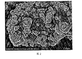
- Example 2 is an SEM image of a molybdenum (Mo) doped modified layered lithium-rich manganese-based cathode material (Li 1.2 Mn 0.49 Mo 0.05 Co 0.13 Ni 0.13 O 2 ) in Example 1 of the present invention
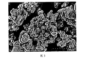
- FIG. 3 is an SEM image of a pure phase layered lithium-rich manganese-based cathode material according to Embodiment 1 of the present invention.
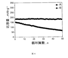
- Example 4 is a cycle curve of a layered lithium-rich manganese-based cathode material before and after molybdenum doping in Example 1 of the present invention
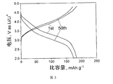
- FIG. 5 is a charge and discharge curve of a test battery made of a molybdenum (Mo) doped modified layered lithium-rich manganese-based positive electrode material in a cycle of 100 cycles according to Embodiment 1 of the present invention
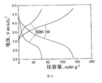
- Example 6 is a graph showing charge and discharge curves of a laboratory battery made of a pure phase layered lithium-rich manganese-based positive electrode material in a cycle of 100 cycles in Example 1 of the present invention.
- the invention provides a molybdenum-doped lithium-rich manganese-based cathode material having the chemical formula of formula I:
- the x may be 0.05, 0.1, 0.25, 0.3 or 0.5.
- the knot having the formula I The positive electrode material is a layered lithium-rich manganese-based positive electrode material doped with molybdenum phase.
- the invention also provides a preparation method of a molybdenum-doped lithium-rich manganese-based cathode material, comprising the following steps:
- step D) sintering the intermediate in the step C) at 450 to 600 ° C for 5 to 8 hours, and then holding at 750 to 950 ° C for 10 to 24 hours to obtain a molybdenum-doped lithium-rich manganese having the formula I Base cathode material;
- the lithium source, the manganese source, the cobalt source and the nickel source are preferably dissolved in deionized water according to the molar ratio in the formula (I: 1.2:0.54:0.13:0.13), and then the respective solutions are mixed to obtain a mixed metal. Salt solution.
- the lithium source is one or more of lithium hydroxide, lithium carbonate and lithium acetate
- the nickel source is one or more of nickel nitrate, nickel sulfate and nickel acetate
- the cobalt source is nitric acid
- the manganese source is one or more of manganese nitrate, manganese sulfate and manganese acetate.
- the concentration of all metal ions in the mixed metal salt solution is preferably from 0.1 to 3 mol/L, more preferably from 0.5 to 2.5 mol/L, and most preferably from 1 to 2 mol/L.
- the concentration of the lithium source solution is preferably 0.1 to 3 mol/L, more preferably 0.5 to 2.5 mol/L, most preferably 1 to 2 mol/L; and the concentration of the manganese source solution is preferably 0.1 to 3 mol/L. It is preferably 0.5 to 2.5 mol/L, and most preferably 1 to 2 mol/L; the concentration of the solution of the cobalt source is preferably 0.1 to 3 mol/L, more preferably 0.5 to 2.5 mol/L, and most preferably 1 to 2 mol/L.
- the concentration of the solution of the nickel source is preferably from 0.1 to 3 mol/L, more preferably from 0.5 to 2.5 mol/L, and most preferably from 1 to 2 mol/L.
- an organic acid is added to the above mixed metal salt solution, and then add a molybdenum source thereto according to a molar ratio in the chemical formula of the formula I, and stir for 1 to 2 hours to obtain a mixed solution.
- the organic acid is preferably one or more of citric acid, tartaric acid and glycine; the molar ratio of the organic acid to all transition metals in the mixed metal salt solution is preferably (1 to 3): 1, more preferably It is 2:1.
- the molybdenum source is preferably one or more of sodium molybdate, ammonia molybdate, and potassium molybdate.
- the temperature of the evaporation is preferably 80 to 120 ° C, more preferably 90 to 110 ° C, most preferably 100 ° C; and the evaporation time is preferably 10 to 15 hours, more preferably 11 to 14 hours, most preferably 12 to 13 hours.
- the gel material is then dried, preferably at a temperature of from 100 to 150 ° C, more preferably from 110 to 140 ° C, most preferably from 120 to 130 ° C; and the drying time is preferably from 10 to 15 hours, more It is preferably 11 to 14 hours, and most preferably 12 to 13 hours.
- the present invention is subjected to ball milling and pulverization to obtain an intermediate.
- the invention sinters the above intermediate, and the specific process of the sintering is:
- the intermediate in the step B) is raised from room temperature to 450 to 600 ° C at a rate of 1 to 5 ° C / min, preferably 500 to 550 ° C, and sintered for 5 to 8 hours, preferably 6 to 7 hours; Increasing to 750-900 ° C, preferably 800-850 ° C at a rate of 1 ⁇ 5 ° C / min, holding for 10 ⁇ 24 hours, preferably 12 ⁇ 20 hours, after natural cooling after sintering, to obtain a molybdenum of formula I Doped lithium-rich manganese-based cathode material.
- the present invention provides a molybdenum-doped lithium-rich manganese-based positive electrode material having the chemical formula of Formula I: Li 1.2 Mn 0.54-x Mo x Co 0.13 Ni 0.13 O 2 Formula I; wherein 0.05 ⁇ x ⁇ 0.5.
- the invention replaces the manganese ion in the layered lithium-rich manganese-based material by metal cation Mo to realize bulk phase doping of the layered lithium-rich manganese-based material, and the molybdenum-doped lithium-rich manganese-based positive electrode in the invention
- the material structure is stable and can reduce voltage attenuation and capacity attenuation during the cycle.
- the invention also provides a preparation method of a molybdenum-doped lithium-rich manganese-based cathode material, which is prepared by a sol-gel method, and the obtained layered lithium-rich manganese-based cathode material has structural stability, thereby improving cycle performance and suppression.
- the pressure drop produced by the cycle is not limited to a molybdenum-doped lithium-rich manganese-based cathode material, which is prepared by a sol-gel method, and the obtained layered lithium-rich manganese-based cathode material has structural stability, thereby improving cycle performance and suppression.
- the pressure drop produced by the cycle is not limited to prepare a molybdenum-doped lithium-rich manganese-based cathode material, which is prepared by a sol-gel method, and the obtained layered lithium-rich manganese-based cathode material has structural stability, thereby improving cycle performance and suppression.
- the pressure drop produced by the cycle is not limited to a molybdenum
- the molar ratio is 1.2:0.54:0.13:0.13, and a certain amount of lithium salt, nickel salt, drill salt and manganese salt are dissolved in deionized water to prepare a concentration of 0.1 mol.
- An aqueous solution of /L and the above solution is mixed.
- Citric acid was added to the above mixed solution in an amount of 1:1 by mole ratio of all transition metal ions to organic acid in the mixed solution.
- the mixed solution obtained above was stirred at 80 ° C for 10 hours until all of the deionized water was evaporated to dryness to obtain a gel material, which was then dried in a dry box at 100 ° C for 10 hours, and then the dried product was taken out for ball milling.
- the crushed powder material was sintered in an air atmosphere at 25 ° C from 1 ° C / min to 450 ° C for 8 h, and then incubated at 1 ° C / min to 750 ° C for 24 h in an air atmosphere, and naturally cooled to room temperature to obtain molybdenum ( Mo) doped modified layered lithium-rich manganese-based positive electrode material (Li 1.2 Mn 0.49 Mo 0.05 Co 0.13 Ni 0.13 O 2 ).
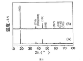
- FIG. 1 is an XRD pattern of (A) molybdenum doped modified layered lithium-rich manganese-based cathode material and (B) pure phase layered lithium-rich manganese-based cathode material in Example 1 of the present invention. .
- the prepared molybdenum (Mo) doped modified layered lithium-rich manganese-based cathode material (Li 1.2 Mn 0.49 Mo 0.05 Co 0.13 Ni 0.13 O 2 ) and conductive carbon black were prepared according to the ratio of 8:1:1 in Example 1: SuperP, binder PVDF was added to N-methylpyrrolidone for stirring and mixing, and the resulting slurry was coated on an aluminum foil and dried at 120 ° C for 12 hours to obtain a positive electrode sheet.
- the battery was assembled in an argon-filled glove box, the negative electrode was a lithium metal plate, the separator was polypropylene, and LiPF 6 was an electrolyte.
- the obtained battery was subjected to a charge and discharge test at a magnification of 1 C, and the obtained cycle curve is shown in FIG. 4 is a cycle curve of a layered lithium-rich manganese-based cathode material before and after molybdenum doping in Example 1 of the present invention.
- a and B in Fig. 4 are cycle curves of the molybdenum (Mo) doped modified and pure layered lithium rich materials obtained in Example 1, respectively.
- 4A the first discharge specific capacity of the molybdenum (Mo) doped layered lithium-rich material prepared in Example 1 was 183.2 mAh/g, and the capacity retention rate reached 98.3% after 100 cycles, but pure.
- the layered lithium-rich material has a capacity retention rate of only 45% after 100 cycles.
- molybdenum (Mo) doping can effectively suppress voltage decay during cycling. It can be seen from the above results that the molybdenum (Mo) doping modification can effectively improve the material cycle stability, and stabilize the material structure to suppress voltage attenuation.
- a certain amount of lithium salt, nickel salt, drill salt and manganese salt are weighed and dissolved in deionized water according to the molar ratio shown in the chemical formula of the layered lithium-rich manganese-based positive electrode material, and are prepared into an aqueous solution having a concentration of 1.5 mol/L, and the above The solution was mixed.
- Tartaric acid was added to the above mixed solution in an amount of 1:1.5 in a molar ratio of all transition metal ions to organic acid in the mixed solution.
- the mixed solution obtained above was stirred at 90 ° C for 12 hours until all of the deionized water was evaporated to dryness to obtain a gel material, which was then dried in a dry box at 120 ° C for 11 hours, and then the dried product was taken out for ball milling.
- the crushed powder material was sintered in an air atmosphere at 25 ° C to 500 ° C for 2 h at 2 ° C / min, and then raised to 800 ° C for 2 h in an air atmosphere at 2 ° C / min, and naturally cooled to room temperature to obtain molybdenum ( Mo) doped modified layered lithium-rich manganese-based positive electrode material (Li 1.2 Mn 0.44 Mo 0.1 Co 0.13 Ni 0.13 O 2 ).
- Electrochemical performance analysis of the molybdenum (Mo) doped modified layered lithium-rich manganese-based cathode material obtained in Example 2 0.8 g of molybdenum (Mo) doped modified layered lithium-rich manganese-based cathode material (Li 1.2 Mn 0.44 Mo 0.1 Co 0.13 Ni 0.13 O 2 ), 0.05 g of acetylene black and 0.05 g of PVDF, 0.4 g of NMP was added and dispersed, and the obtained slurry was coated on an aluminum foil, and dried in an anaerobic glove box with metallic lithium. The film is a counter electrode and assembled into a CR2025 button battery.
- the 1C rate was tested for 100 charge-discharge cycles between 2-4.8 V.
- the results showed that the molybdenum (Mo) doped modified layered lithium-rich manganese-based cathode material (Li 1.2 Mn 0.54-x Mo x Co 0.13 Ni 0.13 O 2 ) has a high specific capacity, is stable in circulation, and can effectively suppress voltage fluctuation of material structure change, and exhibits excellent electrochemical performance.
- a certain amount of lithium salt, nickel salt, drill salt and manganese salt are weighed and dissolved in deionized water according to the molar ratio shown in the chemical formula of the layered lithium-rich manganese-based positive electrode material, and are prepared into an aqueous solution having a concentration of 1.5 mol/L, and the above The solution was mixed.
- the ratio of glycine is 1:2. It is added to the above mixed solution.
- the mixed solution obtained above was stirred at 100 ° C for 13 hours until all of the deionized water was evaporated to dryness to obtain a gel material, which was then dried in a dry box at 125 ° C for 13 hours, and then the dried product was taken out for ball milling.
- Molybdenum (Mo) doped modified layered lithium-rich manganese-based cathode material Li 1.2 Mn 0.29 Mo 0.25 Co 0.13 Ni 0.13 O 2 .
- Electrochemical performance analysis of the molybdenum (Mo) doped modified layered lithium-rich manganese-based cathode material obtained in Example 3 0.8 g of molybdenum (Mo) doped modified layered lithium-rich manganese-based cathode material (Li 1.2 Mn 0.29 Mo 0.25 Co 0.13 Ni 0.13 O 2 ), 0.05 g acetylene black and 0.05 g PVDF, 0.4 g of NMP was mixed and dispersed, and the obtained slurry was coated on an aluminum foil, and dried in an anaerobic glove box with metallic lithium. The film is a counter electrode and assembled into a CR2025 button battery.
- the 1C rate was tested at 100 times charge-discharge cycle between 2-4.8V.
- the results show that the molybdenum (Mo) doped modified layered lithium-rich manganese-based cathode material has high specific capacity, stable cycle, and Effectively suppressing material structure changes produces voltage attenuation and exhibits excellent electrochemical performance.
- a certain amount of lithium salt, nickel salt, drill salt and manganese salt are weighed in deionized water according to the molar ratio shown in the chemical formula of the layered lithium-rich manganese-based positive electrode material, and are prepared into an aqueous solution having a concentration of 2 mol/L, and the above solution is prepared. Mix.
- Citric acid was added to the above mixed solution in an amount of 1:1.3 in a molar ratio of all transition metal ions to organic acid in the mixed solution.
- the mixed solution obtained above was stirred at 110 ° C for 14 hours until all of the deionized water was evaporated to dryness to obtain a gel material, which was then dried in a dry box at 140 ° C for 11 hours, and then the dried material was taken out for ball milling.
- the crushed powder material was sintered in the air atmosphere from 25 ° C to 500 ° C for 7 h in 4 ° C / min, then raised to 900 ° C in air at 4 ° C / min for 15 h, and naturally cooled to room temperature to obtain molybdenum ( Mo) doped modified layered lithium-rich manganese-based positive electrode material (Li 1.2 Mn 0.24 Mo 0.3 Co 0.13 Ni 0.13 O 2 ).
- Electrochemical performance analysis of the molybdenum doped modified layered lithium-rich manganese-based cathode material obtained in Example 4 0.8 g of molybdenum (Mo) doped modified layered lithium-rich manganese-based cathode material (Li 1.2 Mn 0.24) Mo 0.3 Co 0.13 Ni 0.13 O 2 ), 0.05 g of acetylene black and 0.05 g of PVDF, 0.4 g of NMP was mixed and dispersed, and the obtained slurry was coated on an aluminum foil, and dried in an anaerobic glove box with a metal lithium plate as a pair. The electrodes are assembled into a CR2025 button battery.
- the 1C rate was tested at 100 times charge-discharge cycle between 2-4.8V.
- the results show that the molybdenum (Mo) doped layered lithium-rich manganese-based cathode material has high specific capacity, stable cycle, and can be effective. Suppressing material structure changes produces voltage decay and exhibits excellent electrochemical performance.
- a certain amount of lithium salt, nickel salt, drill salt and manganese salt are weighed in deionized water according to the molar ratio shown in the chemical formula of the layered lithium-rich manganese-based positive electrode material, and are prepared into an aqueous solution having a concentration of 3 mol/L, and the above solution is prepared. Mix.
- Tartaric acid was added to the above mixed solution in an amount of 1:3 by mole of all transition metal ions to organic acid in the mixed solution.
- the mixed solution obtained above was stirred at 120 ° C for 15 h until all of the deionized water was evaporated to dryness to obtain a gel material, which was then dried in a dry box at 150 ° C for 10 h, and then the dried material was taken out for ball milling.
- the crushed powder material was sintered from 25 ° C to 600 ° C for 5 h in an air atmosphere at 5 ° C / min, and then incubated at 5 ° C / min to 950 ° C for 10 h in an air atmosphere, and naturally cooled to room temperature to obtain molybdenum ( Mo) doped modified layered lithium-rich manganese-based positive electrode material (Li 1.2 Mn 0.04 Mo 0.5 Co 0.13 Ni 0.13 O 2 ).
- Electrochemical performance analysis of the molybdenum (Mo) doped modified layered lithium-rich manganese-based cathode material obtained in Example 5 0.8 g of molybdenum (Mo) doped modified layered lithium-rich manganese-based cathode material (Li 1.2 Mn 0.04 Mo 0.5 Co 0.13 Ni 0.13 O 2 ), 0.05 g acetylene black and 0.05 g PVDF, 0.4 g of NMP was mixed and dispersed, and the obtained slurry was coated on an aluminum foil, and dried in an anaerobic glove box with metallic lithium. The film is a counter electrode and assembled into a CR2025 button battery.
- the 1C rate was tested at 100 times charge-discharge cycle between 2-4.8V.
- the results show that the molybdenum (Mo) doped layered lithium-rich manganese-based cathode material has high specific capacity, stable cycle, and can be effective. Suppressing material structure changes produces voltage decay and exhibits excellent electrochemical performance.
Landscapes
- Chemical & Material Sciences (AREA)
- Chemical Kinetics & Catalysis (AREA)
- Electrochemistry (AREA)
- General Chemical & Material Sciences (AREA)
- Inorganic Chemistry (AREA)
- Engineering & Computer Science (AREA)
- Materials Engineering (AREA)
- Manufacturing & Machinery (AREA)
- Battery Electrode And Active Subsutance (AREA)
Abstract
一种钼掺杂的富锂锰基正极材料,具有式I所示化学式:Li 1.2Mn 0.54-xMo xCo 0.13Ni 0.13O 2式I;其中,0.05≤x≤0.1。以金属阳离子Mo对层状的富锂锰基材料中的锰离子进行替代,实现对层状富锂锰基材料的体相掺杂,钼掺杂的富锂锰基正极材料结构稳定,能制循环过程中电压衰减和容量衰减。还提供了一种钼掺杂的富锂锰基正极材料的制备方法,采用溶胶凝胶法制备,得到的层状富锂锰基正极材料结构稳定性,从而提高循环性能和抑制循环过程产生的压降。
Description
本申请要求于2017年10月23日提交中国专利局、申请号为201710992179.7、发明名称为“一种钼掺杂的富锂锰基正极材料及其制备方法”的中国专利申请的优先权,其全部内容通过引用结合在本申请中。
本发明属于锂离子电池制造技术领域,尤其涉及一种钼掺杂的富锂锰基正极材料及其制备方法。
随着社会发展,人类面临两大问题是环境污染和能源危机。人类社会发展离不开煤、石油、天然气等不可再生能源,但是这些资源总会有一天被消耗完。于是使得人类开发和发展新的能源技术和形式,提高能源的使用效率,比如,太阳能,地热能和风能等。但是这些新能源技术存在地域性和不连续性,限制了其使用。因此,需要开发出相应储能装置,才能真正实现持续供给能源以达到人类的能源使用需求。
锂离子电池出现给新能源持续利用带来了希望,由于其具有输出电池电压,能量密度高,无记忆效应,循环寿命长,自放电小,安全性能好等多方面优势。锂离子电池包括正极材料,电解液,隔膜和负极材料。正极材料作为锂离子电池关键材料之一,其性能好坏直接关系到电池性能的优劣。与负极材料相对比,正极材料的比容量比较低,比如层状LiCoO2和三元材料,尖晶石结构LiMn2O4和橄榄石型结构LiFePO4等正极材料的比容量都是在200mAh/g以下,严重阻碍锂离子电池获得高能量密度,阻碍其进一步发展。然而,层状富锂材料具有超过250mAh/g容量,并且价格低廉,环境友好,原材料来源丰富,适合大规模工业生产。遗憾的是层状富锂材料存在较差倍率性能,较差循环性能和循环过程中产生电压衰减,严重阻碍其进一步发展。
发明内容
本发明的目的在于提供一种钼掺杂的富锂锰基正极材料及其制备方法,本发明中的钼掺杂的富锂锰基正极材料结构稳定、循环性能好并且能有效抑制循环过程产生的压降。
本发明提供一种钼掺杂的富锂锰基正极材料,具有式I所示化学式:
Li1.2Mn0.54-xMoxCo0.13Ni0.13O2 式I;
其中,0.05≤x≤0.5。
本发明提供一种钼掺杂的富锂锰基正极材料的制备方法,包括以下步骤:
A)将锂源、镍源、钴源和锰源按照式I化学式中的摩尔比溶解于水中,得到混合金属盐溶液;
B)依次将有机酸和钼源加入所述步骤A)中的混合金属盐溶液中,得到混合溶液;
C)蒸干所述步骤B)中的混合溶液中的水分,得到凝胶物质,将所述凝胶物质进行干燥,得到中间体;
D)将所述步骤C)中的中间体在450~600℃下烧结5~8小时,然后在750~950℃下保温10~24小时,得到具有式I化学式的钼掺杂的富锂锰基正极材料;
Li1.2Mn0.54-xMoxCo0.13Ni0.13O2 式I;
其中,0.05≤x≤0.5。
优选的,所述锂源为氢氧化锂,碳酸锂和醋酸锂中的一种或多种;
镍源为硝酸镍,硫酸镍和醋酸镍中的一种或多种;
钴源为硝酸钴,硫酸钴和醋酸钴中的一种或多种;
锰源为硝酸锰,硫酸锰和醋酸锰中的一种或多种。
优选的,所述混合金属盐溶液的浓度为0.1~3mol/L。
优选的,所述有机酸为柠檬酸、酒石酸和甘氨酸中的一种或多种;
所述有机酸与混合溶液中所有过渡金属离子的摩尔比为(1~3):1。
优选的,所述钼源为钼酸钠、钼酸氨和钼酸钾中的一种或多种。
优选的,所述步骤C)中蒸干的温度为80~120℃;
所述步骤C)中蒸干的时间为10~15小时。
优选的,所述步骤C)中干燥的温度为100~150℃;
所述步骤C)中干燥的时间为10~15小时。
优选的,所述步骤C)中烧结的具体过程为:
将所述步骤B)中的中间体以1~5℃/min的速率从室温升至450~600℃,烧结5~8小时;然后在以1~5℃/min的速率升至750~900℃,保温10~24小时,
得到具有式I化学式的钼掺杂的富锂锰基正极材料。
本发明提供了一种钼掺杂的富锂锰基正极材料,具有式I所示化学式:Li1.2Mn0.54-xMoxCo0.13Ni0.13O2 式I;其中,0.05≤x≤0.5。本发明以金属阳离子Mo对层状的富锂锰基材料中的锰离子进行替代,实现对层状富锂锰基材料的体相掺杂,本发明中的钼掺杂的富锂锰基正极材料结构稳定,能制循环过程中电压衰减和容量衰减。
本发明还提供了一种钼掺杂的富锂锰基正极材料的制备方法,本发明采用溶胶凝胶法制备,得到的层状富锂锰基正极材料结构稳定性,从而提高循环性能和抑制循环过程产生的压降。
为了更清楚地说明本发明实施例或现有技术中的技术方案,下面将对实施例或现有技术描述中所需要使用的附图作简单地介绍,显而易见地,下面描述中的附图仅仅是本发明的实施例,对于本领域普通技术人员来讲,在不付出创造性劳动的前提下,还可以根据提供的附图获得其他的附图。
图1为本发明实施例1中钼掺杂改性层状富锂锰基正极材料和纯相层状富锂锰基正极材料的XRD图;
图2为本发明实施例1中钼(Mo)掺杂改性层状富锂锰基正极材料(Li1.2Mn0.49Mo0.05Co0.13Ni0.13O2)的SEM图;
图3为本发明实施例1中纯相层状富锂锰基正极材料的SEM图;
图4为本发明实施例1中层状富锂锰基正极材料经钼掺杂前后的循环曲线;
图5为本发明实施例1中的以钼(Mo)掺杂改性层状富锂锰基正极材料制成的实验电池在100圈循环过程中的充放电曲线;
图6为本发明实施例1中纯相层状富锂锰基正极材料制成的实验电池在100圈循环过程中的充放电曲线。
本发明提供了一种钼掺杂的富锂锰基正极材料,具有式I所示化学式:
Li1.2Mn0.54-xMoxCo0.13Ni0.13O2 式I;
其中,0.05≤x≤0.5。
在本发明中,所述x可以是0.05、0.1、0.25、0.3或0.5。所述具有式I结
构的正极材料为钼体相掺杂的层状富锂锰基正极材料。
本发明还提供了一种钼掺杂的富锂锰基正极材料的制备方法,包括以下步骤:
A)将锂源、镍源、钴源和锰源按照式I化学式中的摩尔比溶解于水中,得到混合金属盐溶液;
B)依次将有机酸和钼源加入所述步骤A)中的混合金属盐溶液中,得到混合溶液;
C)蒸干所述步骤B)中的混合溶液中的水分,得到凝胶物质,将所述凝胶物质进行干燥,得到中间体;
D)将所述步骤C)中的中间体在450~600℃下烧结5~8小时,然后在750~950℃下保温10~24小时,得到具有式I化学式的钼掺杂的富锂锰基正极材料;
Li1.2Mn0.54-xMoxCo0.13Ni0.13O2 式I;
其中,0.05≤x≤0.5。
本发明优选将锂源、锰源、钴源和镍源按照式I化学式中的摩尔比(即1.2:0.54:0.13:0.13)分别溶于去离子水中,然后再将各自溶液混合,得到混合金属盐溶液。在本发明中,所述锂源为氢氧化锂,碳酸锂和醋酸锂中的一种或多种;镍源为硝酸镍,硫酸镍和醋酸镍中的一种或多种;钴源为硝酸钴,硫酸钴和醋酸钴中的一种或多种;锰源为硝酸锰,硫酸锰和醋酸锰中的一种或多种。所述混合金属盐溶液中所有金属离子的浓度优选为0.1~3mol/L,更优选为0.5~2.5mol/L,最优选为1~2mol/L。其中,锂源的溶液的浓度优选为0.1~3mol/L,更优选为0.5~2.5mol/L,最优选为1~2mol/L;锰源的溶液的浓度优选为0.1~3mol/L,更优选为0.5~2.5mol/L,最优选为1~2mol/L;钴源的溶液的浓度优选为0.1~3mol/L,更优选为0.5~2.5mol/L,最优选为1~2mol/L;镍源的溶液的浓度优选为0.1~3mol/L,更优选为0.5~2.5mol/L,最优选为1~2mol/L。
本发明优选先将有机酸加入上述混合金属盐溶液中,然后再按照式I所示化学式中的摩尔比将钼源加入其中,进行搅拌1~2小时,得到混合溶液。所述有机酸优选为柠檬酸、酒石酸和甘氨酸中的一种或多种;所述有机酸与所述混合金属盐溶液中全部过渡金属的摩尔比优选为(1~3):1,更优选为2:1。所述
钼源优选为钼酸钠、钼酸氨和钼酸钾中的一种或多种。
在本发明中,所述蒸干的温度优选为80~120℃,更优选为90~110℃,最优选为100℃;所述蒸干的时间优选为10~15小时,更优选为11~14小时,最优选为12~13小时。本发明优选在搅拌下进行上述蒸干。去离子水全部蒸干后,得到凝胶物质。
然后将上述凝胶物质进行干燥,所述干燥的温度优选为100~150℃,更优选为110~140℃,最优选为120~130℃;所述干燥的时间优选为10~15小时,更优选为11~14小时,最优选为12~13小时。得到干燥物后,本发明将其进行球磨粉碎,得到中间体。
本发明将上述中间体进行烧结,所述烧结的具体过程为:
将所述步骤B)中的中间体以1~5℃/min的速率从室温升至450~600℃,优选为500~550℃,烧结5~8小时,优选为6~7小时;然后在以1~5℃/min的速率升至750~900℃,优选为800~850℃,保温10~24小时,优选为12~20小时,烧结后经自然冷却,得到具有式I化学式的钼掺杂的富锂锰基正极材料。
本发明提供了一种钼掺杂的富锂锰基正极材料,具有式I所示化学式:Li1.2Mn0.54-xMoxCo0.13Ni0.13O2 式I;其中,0.05≤x≤0.5。本发明以金属阳离子Mo对层状的富锂锰基材料中的锰离子进行替代,实现对层状富锂锰基材料的体相掺杂,本发明中的钼掺杂的富锂锰基正极材料结构稳定,能制循环过程中电压衰减和容量衰减。
本发明还提供了一种钼掺杂的富锂锰基正极材料的制备方法,本发明采用溶胶凝胶法制备,得到的层状富锂锰基正极材料结构稳定性,从而提高循环性能和抑制循环过程产生的压降。
为了进一步说明本发明,以下结合实施例对本发明提供的一种钼掺杂的富锂锰基正极材料及其制备方法进行详细描述,但不能将其理解为对本发明保护范围的限定。
实施例1
按照层状富锂锰基正极材料化学式中所示摩尔比为1.2:0.54:0.13:0.13称取一定量锂盐、镍盐、钻盐和锰盐溶解在去离子水中,配制成浓度为0.1mol/L的水溶液,并且将以上溶液进行混合。
按照混合溶液中所有过渡金属离子与有机酸摩尔比为1:1的量将柠檬酸加入到上述混合溶液中。
按照钼掺杂量为x=0.05的量将钼酸铵加入上述混合溶液中,进行搅拌1h。
上述获得的混合溶液在80℃下搅拌10h,直至去离子水全部蒸干,得到凝胶物质,然后放到干燥箱里100℃干燥10h后,取出干燥物进行球磨破碎。
最后将破碎粉体材料在空气气氛中以1℃/min从25℃升到450℃烧结8h,然后再在空气气氛中以1℃/min升到750℃保温24h,自然冷却至室温得到钼(Mo)掺杂改性层状富锂锰基正极材料(Li1.2Mn0.49Mo0.05Co0.13Ni0.13O2)。
对实施例1所得的钼(Mo)掺杂改性层状富锂锰基正极材料(Li1.2Mn0.49Mo0.05Co0.13Ni0.13O2)与实施例1中所得的纯相层状富锂锰基正极材料进行XRD分析和SEM分析。如图1~3所示,图1为本发明实施例1中(A)钼掺杂改性层状富锂锰基正极材料和(B)纯相层状富锂锰基正极材料的XRD图。由XRD图所知,钼(Mo)掺杂改性后层状富锂锰基正极材料与改性前层状富锂材料衍射峰相一致,说明钼(Mo)掺杂不改变层状富锂锰基正极材料物相结构。图2为本发明实施例1中钼(Mo)掺杂改性层状富锂锰基正极材料(Li1.2Mn0.49Mo0.05Co0.13Ni0.13O2)的SEM图,图3为本发明实施例1中纯相层状富锂锰基正极材料的SEM图。由图2和图3对比可知,钼(Mo)掺杂后,材料的微观结构没有发生变化。
将实施例1按照8:1:1的比例将制备好的钼(Mo)掺杂改性层状富锂锰基正极材料(Li1.2Mn0.49Mo0.05Co0.13Ni0.13O2)、导电炭黑SuperP、粘结剂PVDF加入N-甲基砒咯烷酮进行搅拌混合,然后所得的浆料涂覆在铝箔上,在120℃下干燥12小时得到正极片。在充满氩气的手套箱中进行电池组装,负极为金属锂片,隔膜为聚丙烯,LiPF6为电解液。将所得实施电池在倍率为1C倍率下进行充放电测试,所得的循环曲线如图4所示。图4为本发明实施例1中层状富锂锰基正极材料经钼掺杂前后的循环曲线。
图4中A和B分别是实施例1制得的钼(Mo)掺杂改性和纯层状富锂材料的循环曲线。由图4A可知,由实施例1制得的钼(Mo)掺杂改性的层状富锂材料首次放电比容量为183.2mAh/g,经过100次循环后容量保持率达到98.3%,可是纯层状富锂材料经过100次循环后容量保持率只有45%。通过图
5与图6之间对比能够看出钼(Mo)掺杂能够有效抑制循环过程中电压衰减。由以上结果可知,采用钼(Mo)掺杂改性后能够有效提高材料循环稳定性,并且稳定材料结构抑制电压衰减。
实施例2
按照层状富锂锰基正极材料化学式中所示摩尔比称取一定量锂盐、镍盐、钻盐和锰盐溶解在去离子水中,配制成浓度为1.5mol/L的水溶液,并且将以上溶液进行混合。
按照混合溶液中所有过渡金属离子与有机酸摩尔比为1:1.5的量将酒石酸加入到上述混合溶液中。
按照钼掺杂量为x=0.1的量将钼酸钠加入上述混合溶液中,进行搅拌1.5h。
上述获得的混合溶液在90℃下搅拌12h,直至去离子水全部蒸干,得到凝胶物质,然后放到干燥箱里120℃干燥11h后,取出干燥物进行球磨破碎。
最后将破碎粉体材料在空气气氛中以2℃/min从25℃升到500℃烧结6h,然后再在空气气氛中以2℃/min升到800℃保温12h,自然冷却至室温得到钼(Mo)掺杂改性层状富锂锰基正极材料(Li1.2Mn0.44Mo0.1Co0.13Ni0.13O2)。
对实施例2所得的钼(Mo)掺杂改性层状富锂锰基正极材料进行电化学性能分析:称取0.8g钼(Mo)掺杂改性层状富锂锰基正极材料(Li1.2Mn0.44Mo0.1Co0.13Ni0.13O2),0.05g乙炔黑和0.05gPVDF,加入0.4g的NMP分散混合,所得浆料涂覆在铝箔上,烘干后在厌氧手套箱中以金属锂片为对电极,组装成CR2025扣式电池。在25℃下,1C倍率在2-4.8V间进行100次充放电循环测试,结果表明钼(Mo)掺杂改性层状富锂锰基正极材料(Li1.2Mn0.54-xMoxCo0.13Ni0.13O2)具有较高比容量,循环稳定,并且能够有效抑制材料结构变化产生电压衰减,表现出优异电化学性能。
实施例3
按照层状富锂锰基正极材料化学式中所示摩尔比称取一定量锂盐、镍盐、钻盐和锰盐溶解在去离子水中,配制成浓度为1.5mol/L的水溶液,并且将以上溶液进行混合。
按照混合溶液中所有过渡金属离子与有机酸摩尔比为1:2的量将甘氨酸
加入到上述混合溶液中。
按照钼掺杂量为x=0.25的量将钼酸钠源加入上述混合溶液中,进行搅拌1.5h。
上述获得的混合溶液在100℃下搅拌13h,直至去离子水全部蒸干,得到凝胶物质,然后放到干燥箱里125℃干燥13h后,取出干燥物进行球磨破碎。
最后将破碎粉体材料在空气气氛中以3℃/min从25℃升到525℃烧结5-8h,然后再在空气气氛中以3℃/min升到850℃保温17h,自然冷却至室温得到钼(Mo)掺杂改性层状富锂锰基正极材料(Li1.2Mn0.29Mo0.25Co0.13Ni0.13O2)。
对实施例3所得的钼(Mo)掺杂改性层状富锂锰基正极材料进行电化学性能分析:称取0.8g钼(Mo)掺杂改性层状富锂锰基正极材料(Li1.2Mn0.29Mo0.25Co0.13Ni0.13O2),0.05g乙炔黑和0.05gPVDF,加入0.4g的NMP分散混合,所得浆料涂覆在铝箔上,烘干后在厌氧手套箱中以金属锂片为对电极,组装成CR2025扣式电池。在25℃下,1C倍率在2-4.8V间进行100次充放电循环测试,结果表明钼(Mo)掺杂改性层状富锂锰基正极材料具有较高比容量,循环稳定,并且能够有效抑制材料结构变化产生电压衰减,表现出优异电化学性能。
实施例4
按照层状富锂锰基正极材料化学式中所示摩尔比称取一定量锂盐、镍盐、钻盐和锰盐溶解在去离子水中,配制成浓度为2mol/L的水溶液,并且将以上溶液进行混合。
按照混合溶液中所有过渡金属离子与有机酸摩尔比为1:1.3的量将柠檬酸加入到上述混合溶液中。
按照钼掺杂量为x=0.3的量将钼酸铵加入上述混合溶液中,进行搅拌1.2h。
上述获得的混合溶液在110℃下搅拌14h,直至去离子水全部蒸干,得到凝胶物质,然后放到干燥箱里140℃干燥11h后,取出干燥物进行球磨破碎。
最后将破碎粉体材料在空气气氛中以4℃/min从25℃升到500℃烧结7h,然后再在空气气氛中以4℃/min升到900℃保温15h,自然冷却至室温得到钼(Mo)掺杂改性层状富锂锰基正极材料(Li1.2Mn0.24Mo0.3Co0.13Ni0.13O2)。
对实施例4所得的钼掺杂改性层状富锂锰基正极材料进行电化学性能分析:称取0.8g钼(Mo)掺杂改性层状富锂锰基正极材料(Li1.2Mn0.24Mo0.3Co0.13Ni0.13O2),0.05g乙炔黑和0.05gPVDF,加入0.4g的NMP分散混合,所得浆料涂覆在铝箔上,烘干后在厌氧手套箱中以金属锂片为对电极,组装成CR2025扣式电池。在25℃下,1C倍率在2-4.8V间进行100次充放电循环测试,结果表明钼(Mo)掺杂的层状富锂锰基正极材料具有较高比容量,循环稳定,并且能够有效抑制材料结构变化产生电压衰减,表现出优异电化学性能。
实施例5
按照层状富锂锰基正极材料化学式中所示摩尔比称取一定量锂盐、镍盐、钻盐和锰盐溶解在去离子水中,配制成浓度为3mol/L的水溶液,并且将以上溶液进行混合。
按照混合溶液中所有过渡金属离子与有机酸摩尔比为1:3的量将酒石酸加入到上述混合溶液中。
按照钼掺杂量为x=0.5的量将钼酸铵加入上述混合溶液中,进行搅拌2h。
上述获得的混合溶液在120℃下搅拌15h,直至去离子水全部蒸干,得到凝胶物质,然后放到干燥箱里150℃干燥10h后,取出干燥物进行球磨破碎。
最后将破碎粉体材料在空气气氛中以5℃/min从25℃升到600℃烧结5h,然后再在空气气氛中以5℃/min升到950℃保温10h,自然冷却至室温得到钼(Mo)掺杂改性层状富锂锰基正极材料(Li1.2Mn0.04Mo0.5Co0.13Ni0.13O2)。
对实施例5所得的钼(Mo)掺杂改性层状富锂锰基正极材料进行电化学性能分析:称取0.8g钼(Mo)掺杂改性层状富锂锰基正极材料(Li1.2Mn0.04Mo0.5Co0.13Ni0.13O2),0.05g乙炔黑和0.05gPVDF,加入0.4g的NMP分散混合,所得浆料涂覆在铝箔上,烘干后在厌氧手套箱中以金属锂片为对电极,组装成CR2025扣式电池。在25℃下,1C倍率在2-4.8V间进行100次充放电循环测试,结果表明钼(Mo)掺杂的层状富锂锰基正极材料具有较高比容量,循环稳定,并且能够有效抑制材料结构变化产生电压衰减,表现出优异电化学性能。
以上所述仅是本发明的优选实施方式,应当指出,对于本技术领域的普通
技术人员来说,在不脱离本发明原理的前提下,还可以做出若干改进和润饰,这些改进和润饰也应视为本发明的保护范围。
Claims (9)
- 一种钼掺杂的富锂锰基正极材料,具有式I所示化学式:Li1.2Mn0.54-xMoxCo0.13Ni0.13O2 式I;其中,0.05≤x≤0.5。
- 一种钼掺杂的富锂锰基正极材料的制备方法,包括以下步骤:A)将锂源、镍源、钴源和锰源按照式I化学式中的摩尔比溶解于水中,得到混合金属盐溶液;B)依次将有机酸和钼源加入所述步骤A)中的混合金属盐溶液中,得到混合溶液;C)蒸干所述步骤B)中的混合溶液中的水分,得到凝胶物质,将所述凝胶物质进行干燥,得到中间体;D)将所述步骤C)中的中间体在450~600℃下烧结5~8小时,然后在750~950℃下保温10~24小时,得到具有式I化学式的钼掺杂的富锂锰基正极材料;Li1.2Mn0.54-xMoxCo0.13Ni0.13O2 式I;其中,0.05≤x≤0.5。
- 根据权利要求2所述的制备方法,其特征在于,所述锂源为氢氧化锂,碳酸锂和醋酸锂中的一种或多种;镍源为硝酸镍,硫酸镍和醋酸镍中的一种或多种;钴源为硝酸钴,硫酸钴和醋酸钴中的一种或多种;锰源为硝酸锰,硫酸锰和醋酸锰中的一种或多种。
- 根据权利要求2所述的制备方法,其特征在于,所述混合金属盐溶液的浓度为0.1~3mol/L。
- 根据权利要求2所述的制备方法,其特征在于,所述有机酸为柠檬酸、酒石酸和甘氨酸中的一种或多种;所述有机酸与混合溶液中所有过渡金属离子的摩尔比为(1~3):1。
- 根据权利要求2所述的制备方法,其特征在于,所述钼源为钼酸钠、钼酸氨和钼酸钾中的一种或多种。
- 根据权利要求2所述的制备方法,其特征在于,所述步骤C)中蒸干的温度为80~120℃;所述步骤C)中蒸干的时间为10~15小时。
- 根据权利要求2所述的制备方法,其特征在于,所述步骤C)中干燥的温度为100~150℃;所述步骤C)中干燥的时间为10~15小时。
- 根据权利要求2所述的制备方法,其特征在于,所述步骤C)中烧结的具体过程为:将所述步骤B)中的中间体以1~5℃/min的速率从室温升至450~600℃,烧结5~8小时;然后在以1~5℃/min的速率升至750~900℃,保温10~24小时,得到具有式I化学式的钼掺杂的富锂锰基正极材料。
Applications Claiming Priority (2)
| Application Number | Priority Date | Filing Date | Title |
|---|---|---|---|
| CN201710992179.7 | 2017-10-23 | ||
| CN201710992179.7A CN107768664A (zh) | 2017-10-23 | 2017-10-23 | 一种钼掺杂的富锂锰基正极材料及其制备方法 |
Publications (1)
| Publication Number | Publication Date |
|---|---|
| WO2019080310A1 true WO2019080310A1 (zh) | 2019-05-02 |
Family
ID=61269870
Family Applications (1)
| Application Number | Title | Priority Date | Filing Date |
|---|---|---|---|
| PCT/CN2017/116377 Ceased WO2019080310A1 (zh) | 2017-10-23 | 2017-12-15 | 一种钼掺杂的富锂锰基正极材料及其制备方法 |
Country Status (2)
| Country | Link |
|---|---|
| CN (1) | CN107768664A (zh) |
| WO (1) | WO2019080310A1 (zh) |
Families Citing this family (6)
| Publication number | Priority date | Publication date | Assignee | Title |
|---|---|---|---|---|
| KR102757221B1 (ko) * | 2018-11-28 | 2025-01-21 | 현대자동차주식회사 | 리튬 이차전지 및 리튬 이차전지의 제조방법 |
| CN110642303A (zh) * | 2019-08-30 | 2020-01-03 | 广东新凌嘉新能源股份有限公司 | 一种改进的动力三元圆柱锂电池正极材料及其制备方法 |
| CN112062167B (zh) * | 2020-08-28 | 2023-09-22 | 常熟理工学院 | 一种微米级二元掺杂富锂材料及其制备方法和应用 |
| CN112850792A (zh) * | 2020-12-31 | 2021-05-28 | 湖南信达新材料有限公司 | 一种锂电池正极材料掺钼方法 |
| CN118420003A (zh) * | 2024-05-31 | 2024-08-02 | 格林美股份有限公司 | 一种高稳定性的富锂锰基正极材料及其制备方法和用途 |
| CN121331815A (zh) * | 2025-12-12 | 2026-01-13 | 天津常兴新能源科技有限公司 | 一种掺杂型富锂锰基正极材料及其制备方法 |
Citations (5)
| Publication number | Priority date | Publication date | Assignee | Title |
|---|---|---|---|---|
| US20080261115A1 (en) * | 2007-03-08 | 2008-10-23 | Motoharu Saito | Non-aqueous electrolyte secondary battery and positive electrode |
| CN103413935A (zh) * | 2013-08-27 | 2013-11-27 | 上海电力学院 | 一种掺杂Mo的富锂正极材料及其制备方法 |
| CN103956478A (zh) * | 2014-05-07 | 2014-07-30 | 北京理工大学 | 一种高比容量富锂正极材料的制备方法 |
| CN104900857A (zh) * | 2015-06-02 | 2015-09-09 | 上海电力学院 | 一种微量Mo掺杂的层状富锂三元正极材料的制备方法 |
| CN106711434A (zh) * | 2015-08-05 | 2017-05-24 | 北京化工大学 | 一种类海胆状含钠富锂层状正极材料及其制备方法 |
Family Cites Families (2)
| Publication number | Priority date | Publication date | Assignee | Title |
|---|---|---|---|---|
| CN103515593A (zh) * | 2013-10-14 | 2014-01-15 | 武汉大学 | 复合阳离子掺杂锰基固溶体正极材料及制备方法 |
| CN105118985A (zh) * | 2015-08-27 | 2015-12-02 | 北大先行科技产业有限公司 | 一种晶粒尺寸可调的锂离子电池正极材料及其制备方法 |
-
2017
- 2017-10-23 CN CN201710992179.7A patent/CN107768664A/zh active Pending
- 2017-12-15 WO PCT/CN2017/116377 patent/WO2019080310A1/zh not_active Ceased
Patent Citations (5)
| Publication number | Priority date | Publication date | Assignee | Title |
|---|---|---|---|---|
| US20080261115A1 (en) * | 2007-03-08 | 2008-10-23 | Motoharu Saito | Non-aqueous electrolyte secondary battery and positive electrode |
| CN103413935A (zh) * | 2013-08-27 | 2013-11-27 | 上海电力学院 | 一种掺杂Mo的富锂正极材料及其制备方法 |
| CN103956478A (zh) * | 2014-05-07 | 2014-07-30 | 北京理工大学 | 一种高比容量富锂正极材料的制备方法 |
| CN104900857A (zh) * | 2015-06-02 | 2015-09-09 | 上海电力学院 | 一种微量Mo掺杂的层状富锂三元正极材料的制备方法 |
| CN106711434A (zh) * | 2015-08-05 | 2017-05-24 | 北京化工大学 | 一种类海胆状含钠富锂层状正极材料及其制备方法 |
Also Published As
| Publication number | Publication date |
|---|---|
| CN107768664A (zh) | 2018-03-06 |
Similar Documents
| Publication | Publication Date | Title |
|---|---|---|
| CN110277540B (zh) | 一种核壳结构钠离子电池正极材料及其制备方法和用途 | |
| WO2019080310A1 (zh) | 一种钼掺杂的富锂锰基正极材料及其制备方法 | |
| CN114203949A (zh) | 一种层状锰基钠离子电池正极材料及制备方法和应用 | |
| CN108123128A (zh) | 一种表层掺杂Al3+的NCM三元正极材料的制备方法 | |
| CN114447300B (zh) | 隧道相和层状相复合结构的钠离子电池正极材料的制备方法、制得的材料及其应用 | |
| CN105161703A (zh) | 用于钠离子电池的五元层状氧化物正极材料及其制备方法 | |
| CN108091854A (zh) | 一种阴阳离子复合掺杂的高电压尖晶石型锂离子电池正极材料及其制备方法 | |
| CN118919714A (zh) | 一种钠离子电池p2型镍锰基层状氧化物正极材料及其制备方法 | |
| CN114335661A (zh) | 一种提升中性水系可充电锌锰电池稳定性的电解液添加剂和电解液 | |
| CN111525109B (zh) | 一种包覆钛钴涂层的层状镍锰二元正极材料制备方法 | |
| CN101582496A (zh) | 一种锂离子电池正极材料磷酸亚铁锂/碳的制法 | |
| WO2019104948A1 (zh) | 一种钼掺杂改性的锰酸锂复合材料、其制备方法及锂离子电池 | |
| CN105702951A (zh) | 一种多重联动改性的富锂锰基材料及其改性方法 | |
| CN109279663B (zh) | 一种硼酸盐类钠离子电池负极材料及其制备和应用 | |
| CN107834054B (zh) | 一种锂离子电池用镍锰酸锂-石墨烯复合材料的制备方法 | |
| CN114420937A (zh) | 一种双阳离子共掺杂的高镍三元层状正极材料及其制备方法和应用 | |
| CN115312753A (zh) | 正极补锂材料及其制备和在锂离子电池正极补锂中的应用 | |
| CN108832085A (zh) | 一种可调控低温燃烧法制备富锂正极材料的方法 | |
| ZHONG et al. | Synthesis and electrochemical performances of LiNi0. 6Co0. 2Mn0. 2O2 cathode materials | |
| CN104201346B (zh) | 一种具有优良电化学性能的非化学计量比磷酸盐正极材料的制备方法及应用 | |
| CN102637853A (zh) | 一种锂离子电池正极复合材料的制备方法 | |
| CN117577844A (zh) | 铌氧化物复合储能材料及其制备方法和应用 | |
| CN1785799A (zh) | 过渡元素掺杂磷酸铁锂粉体的制备方法 | |
| CN105514415B (zh) | 一种锂离子电池多元富锂正极材料及其制备方法与应用 | |
| CN104282888B (zh) | 一种用作锂离子电池正极材料的三氧化钼及其制备方法 |
Legal Events
| Date | Code | Title | Description |
|---|---|---|---|
| 121 | Ep: the epo has been informed by wipo that ep was designated in this application |
Ref document number: 17929905 Country of ref document: EP Kind code of ref document: A1 |
|
| NENP | Non-entry into the national phase |
Ref country code: DE |
|
| 122 | Ep: pct application non-entry in european phase |
Ref document number: 17929905 Country of ref document: EP Kind code of ref document: A1 |