WO2019077793A1 - Insulating cover material for stator coils and rotary machine using same - Google Patents
Insulating cover material for stator coils and rotary machine using same Download PDFInfo
- Publication number
- WO2019077793A1 WO2019077793A1 PCT/JP2018/019885 JP2018019885W WO2019077793A1 WO 2019077793 A1 WO2019077793 A1 WO 2019077793A1 JP 2018019885 W JP2018019885 W JP 2018019885W WO 2019077793 A1 WO2019077793 A1 WO 2019077793A1
- Authority
- WO
- WIPO (PCT)
- Prior art keywords
- particles
- particle
- core
- mica
- stator
- Prior art date
Links
Images


Classifications
-
- H—ELECTRICITY
- H01—ELECTRIC ELEMENTS
- H01B—CABLES; CONDUCTORS; INSULATORS; SELECTION OF MATERIALS FOR THEIR CONDUCTIVE, INSULATING OR DIELECTRIC PROPERTIES
- H01B17/00—Insulators or insulating bodies characterised by their form
- H01B17/56—Insulating bodies
- H01B17/60—Composite insulating bodies
-
- H—ELECTRICITY
- H01—ELECTRIC ELEMENTS
- H01B—CABLES; CONDUCTORS; INSULATORS; SELECTION OF MATERIALS FOR THEIR CONDUCTIVE, INSULATING OR DIELECTRIC PROPERTIES
- H01B3/00—Insulators or insulating bodies characterised by the insulating materials; Selection of materials for their insulating or dielectric properties
- H01B3/02—Insulators or insulating bodies characterised by the insulating materials; Selection of materials for their insulating or dielectric properties mainly consisting of inorganic substances
- H01B3/04—Insulators or insulating bodies characterised by the insulating materials; Selection of materials for their insulating or dielectric properties mainly consisting of inorganic substances mica
-
- H—ELECTRICITY
- H01—ELECTRIC ELEMENTS
- H01F—MAGNETS; INDUCTANCES; TRANSFORMERS; SELECTION OF MATERIALS FOR THEIR MAGNETIC PROPERTIES
- H01F5/00—Coils
- H01F5/06—Insulation of windings
-
- H—ELECTRICITY
- H02—GENERATION; CONVERSION OR DISTRIBUTION OF ELECTRIC POWER
- H02K—DYNAMO-ELECTRIC MACHINES
- H02K15/00—Methods or apparatus specially adapted for manufacturing, assembling, maintaining or repairing of dynamo-electric machines
- H02K15/12—Impregnating, heating or drying of windings, stators, rotors or machines
-
- H—ELECTRICITY
- H02—GENERATION; CONVERSION OR DISTRIBUTION OF ELECTRIC POWER
- H02K—DYNAMO-ELECTRIC MACHINES
- H02K3/00—Details of windings
- H02K3/30—Windings characterised by the insulating material
-
- H—ELECTRICITY
- H02—GENERATION; CONVERSION OR DISTRIBUTION OF ELECTRIC POWER
- H02K—DYNAMO-ELECTRIC MACHINES
- H02K3/00—Details of windings
- H02K3/32—Windings characterised by the shape, form or construction of the insulation
- H02K3/34—Windings characterised by the shape, form or construction of the insulation between conductors or between conductor and core, e.g. slot insulation
Definitions
- the present invention relates to an insulating covering material used for a stator coil of a rotating machine, and a rotating machine using the same.
- a large-sized rotating machine used for a turbine generator or the like has a stator coil housed in a plurality of slots formed on the inner peripheral side of a stator core.
- the stator coil is composed of a coil conductor and an insulating covering material wound around it.
- an insulating tape obtained by bonding a fiber reinforcing material such as glass cloth to a mica sheet is wound around the coil conductor a plurality of times, and a low viscosity liquid thermosetting resin composition (insulating varnish) is obtained.
- a method of heat pressing after impregnation under reduced pressure (vacuum pressure impregnation method) or a method of placing a semi-cured resin on an insulating tape, winding this tape around a coil conductor and then heating pressing (resin rich method) are generally used.
- stator coils are housed in upper and lower two stages in the slot, and a spacer is inserted between these stator coils and the stator coil is fixed to the open end of the slot By inserting the wedge, the electromagnetic vibration generated from the stator coil during operation of the rotating machine is suppressed.
- the stator coil In such a rotating machine, the stator coil generates heat due to the current flowing through the coil conductor during operation. If the temperature of the stator coil rises due to this heat generation, there is a fear that the insulation of the stator coil may be deteriorated due to thermal expansion of the coil conductor made of metal such as copper or thermal degradation of the resin component contained in the insulation coating material. There is.
- the thermal conductivity of the insulation coating material is very small compared to the thermal conductivity of other materials such as the coil conductor and the stator core, so it is necessary to increase the thermal conductivity of the insulation coating material
- forced rotation methods such as water direct cooling method and hydrogen indirect cooling method are adopted in rotating machines where large current flows, such as turbine generators, and it is strongly desired to increase the thermal conductivity of the insulation coating of stator coils ing.
- the insulation coating material of the stator coil is also desired to improve the withstand voltage performance.
- a conventional stator coil insulation coating material includes a mica layer, a reinforcing layer laminated on the mica layer and containing filler particles and a fiber reinforcing material, and a cellulose derivative layer laminated on the reinforcing layer.
- An insulating covering material is disclosed (see, for example, Patent Document 1).
- the insulation coating material comprised with the filler layer containing a mica layer and a filler particle as an insulation coating material of another stator coil what used the scale-like hexagonal boron nitride filler particle as a filler particle is disclosed. (See, for example, Patent Document 2).
- the generation of the electrical tree can not be suppressed, and it is difficult to improve the withstand voltage performance.
- the present invention has been made to solve the problems as described above, and it is an object of the present invention to simultaneously achieve high thermal conductivity and high withstand voltage of the insulation coating material of the stator coil.
- the insulation coating material of the stator coil according to the present invention has the mica layer containing mica and the reinforcing layer laminated on the mica layer and containing the filler particles and the reinforcing material, and the filler particles have an average particle diameter of
- the composite particle is composed of core particles of 1 ⁇ m or more and a plurality of fine particles having an average particle diameter of 300 nm or less fixed on the surface of the core particles.
- the present invention uses composite particles composed of core particles and a plurality of fine particles fixed on the surface of the core particles as the filler particles of the reinforcing layer. Coexistence with high withstand voltage can be realized.
- FIG. 1 is a schematic view showing an enlarged part of a stator of a rotary machine according to Embodiment 1 for carrying out the present invention.
- stator coils 3 are accommodated in two stages in slots 2 of a stator core 1.
- a spacer is inserted between the two stages of stator coils 3 (not shown), and a wedge 4 for fixing the stator coil 3 is inserted into the open end of the slot 2.
- the wedge 4 has an effect of suppressing electromagnetic vibration generated from the stator coil 3 at the time of operation of the rotating machine.
- the stator coil 3 is composed of a coil conductor 5 and an insulating covering material 6 wound around the outer periphery of the coil conductor 5.
- the coil conductor 5 can use, for example, a strand of copper, aluminum, silver or the like.
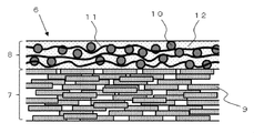
- FIG. 2 is a schematic cross-sectional view of the insulating covering material 6 in the present embodiment.
- the insulating covering material 6 of the present embodiment is configured of a mica layer 7 and a reinforcing layer 8 laminated on the mica layer.
- the mica layer 7 and the reinforcing layer 8 are filled with an insulating resin material 12.
- the mica layer 7 is composed of mica particles 9.
- mica particles 9 it is possible to use scale-like mica, for example, hard mica or soft mica which is a layered silicate rim mineral.
- examples of the form of the mica particles 9 include block mica, peeled mica, and assembled mica. Among these, it is preferable to use an integrated mica having a uniform thickness and an economic advantage.
- the mica layer 7 is configured by laminating flat surfaces of scaly mica particles 9 in the thickness direction of the mica layer. These mica particles are present in such a manner that the particles to be stacked overlap each other, or the particles are shifted in the surface direction.
- the density of the mica layer 7 is preferably 100 to 200 g / m 2 of the mica layer. Within this range, the balance between the withstand voltage performance and the film thickness of the mica layer is good, and the electrical insulating property and the workability for forming the insulating coating material around the coil conductor are compatible.
- These mica particles are obtained by micronizing the ore of mica by water grinding, shear grinding or the like.
- the average particle size of the mica particles is desirably 50 to 800 ⁇ m.
- the average particle size of the mica particles can be measured by a laser diffraction type particle size distribution analyzer.
- the thickness of the scaly mica particles is preferably 30 ⁇ m or less, and more preferably 15 ⁇ m or less.
- the reinforcing layer 8 is laminated on the mica layer 7 and is provided to maintain the strength of the insulating covering material 6 and to improve the workability in the process of winding the insulating covering material 6 around the outer periphery of the coil conductor 5.
- the reinforcing layer 8 is composed of the filler particles 10 and the reinforcing material 11.
- a fibrous material or a film-like material can be used as the reinforcing material 11.
- a fibrous material glass fiber, alumina fiber, polyamide fiber etc. can be used, for example.
- a film-form material a polyimide film, a polyamide film, a polyester film etc. can be used, for example.
- glass fiber is excellent in terms of properties and price. Although there are glass fibers subjected to a coupling treatment on the surface for the purpose of improving the adhesion to the resin, it is preferable that the glass fibers be untreated because this treatment tends to lower the strength of the glass fibers themselves.
- the weight of those deposits is preferably 3% or less of the glass fiber weight.
- the above adhesion weight ratio can be estimated as a weight loss when the glass fiber is heated at 900 ° C. for 30 hours. When the adhesion weight ratio exceeds 3%, peeling occurs between the resin and the glass fiber in aged use, and the insulation performance is reduced.
- the filler particles 10 are held in the gaps of the reinforcing material 11.
- the reinforcing material 11 is a fibrous material, it is held between the fibers, and when the reinforcing material 11 is a film-like material, it is held between the layers of the film.
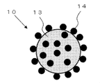
- FIG. 3 is a schematic view of the filler particle 10 in the present embodiment.
- the filler particle 10 is a composite particle composed of a core particle 13 having a particle size of 1 ⁇ m or more and a plurality of fine particles 14 having an average particle size of 300 nm or less fixed to the surface of the core particle 13.
- the core particles 13 are insulating inorganic particles such as silica, boron nitride, alumina, magnesia, aluminum nitride, magnesium hydroxide, magnesium oxide, calcium carbonate and magnesium carbonate.
- the thermal conductivity of these insulating inorganic particles is higher than the thermal conductivity of the resin material filled in the reinforcing layer, so the thermal conductivity of the reinforcing layer can be improved.
- the core particle 13 is preferably a spherical dense particle. If it is spherical, suppression of mechanical destruction, such as a crack at the time of the stress load to insulation coating material, and suppression of the dielectric breakdown by the electric field concentration of particle periphery can be anticipated.
- the dense particles that is, the inside of the particles be free of voids and be filled with the above-described insulating material. The packing of the insulating material improves the thermal conductivity inside the particle, and as a result, the thermal conductivity of the reinforcing layer improves.
- the particle size said here is a value obtained by observing the cross section of insulation coating material with an electron microscope, and observing the particle size of the particle
- the fine particles 14 are also insulating inorganic particles such as silica, boron nitride, alumina, magnesia, aluminum nitride, magnesium hydroxide, magnesium oxide, calcium carbonate and magnesium carbonate.
- the fine particles 14 are mechanically or chemically fixed to the surface of the core particle 13.
- the filler particle 10 By forming the filler particle 10 as a composite particle including the core particle 13 having a particle diameter of 1 ⁇ m to 100 ⁇ m and the plurality of fine particles 14 having an average particle diameter of 300 nm or less fixed on the surface of the core particle 13, The ability to increase the withstand voltage of the insulation coating material will be described next.
- an electrical tree may occur inside the insulating resin filled in the reinforcing layer.
- the electrical tree propagates in the resin in a lightning-like manner, but when the front end of the electrical tree reaches the filler particle, it propagates along the interface between the filler particle and the resin, that is, the surface of the filler particle. The reason is that the difference between the dielectric constant of the filler particles and the dielectric constant of the resin causes the surface of the filler particles to locally increase the electric field strength.
- the tip of the electrical tree reaching the surface of the filler particle travels along the surface of the filler particle according to the electric field strength distribution substantially uniformly distributed on the surface of the filler particle Be
- the filler particles were composite particles composed of core particles and fine particles
- the electric field strength distribution on the surface of the core particles reached the surface of the core particles because the cloth was deformed largely due to the presence of the fine particles.
- the tip of the electrical tree will diverge and evolve. It is believed that part of the branched electrical tree spreads to the resin away from the filler particles, and the development of the electrical tree is suppressed because the electric field strength is lower than that of the surface of the core particle.
- the interparticle distance of the plurality of fine particles on the surface of the core particle is 500 nm or less.
- the probability that an electrical tree traveling on the surface of the core particle encounters the microparticles and is branched increases.
- the number of the fine particles fixed to the outer peripheral part of the hemisphere of the core particle is other than the hemisphere. It is preferably 25% or more and 400% or less of the number of particles fixed to the outer peripheral portion, and more preferably 50% or more and 200% or less. Within these ranges, there is a high probability that the tip of the electrical tree reaching the surface of the core particle is branched even if the electrical tree develops from all directions of the filler particles.
- the electrical tree will become those when the tip of the electrical tree reaches the surface of the core particle or particulate.
- the probability of branching is low only by progressing according to the electric field intensity distribution distributed almost uniformly on the surface of the particles of. As a result, the effect of suppressing the development of the electrical tree is small.
- the particle size of the core particle 13 constituting the composite particle needs to be 1 ⁇ m or more and 100 ⁇ m or less. If the particle size of the core particle is smaller than 1 ⁇ m, the thermal conductivity at the interface between the resin and the core particle is increased, the effect of improving the thermal conductivity by the core particle is reduced, and the desired high thermal conductivity effect can not be obtained. is there.
- the particle size of the core particles exceeds 100 ⁇ m and the thickness of the coil insulating material is constant, the thickness of the reinforcing layer 8 increases due to the increase of the particle size, so the thickness of the mica layer 7 becomes relatively thin and the insulation coating There is a problem that the strength of the material decreases. Furthermore, when the thickness of the insulating covering material is increased when the particle size of the particles exceeds 100 ⁇ m, there is a problem that the thermal resistance of the insulating covering material increases and the heat dissipation decreases.
- the particle diameter of the fine particles 14 constituting the composite particles needs to be 300 nm or less. If the particle size of the fine particles exceeds 300 nm, the probability of the electric tree developing on the surface of the fine particles without branching is high, so that there is a problem that the effect of the fine particles on suppressing the progress of the electric tree decreases.
- the partial discharge repeatedly occurs due to high electric field stress inside the insulation coating material, and the voids resulting from the thermal decomposition of the resin are generated and enlarged.
- the withstand voltage performance of the resin it is preferable to improve the adhesion between the surface of the core particles and the fine particles and the resin.
- the coupling agent for surface modification of these particles can be appropriately selected according to the type of the resin, but when the resin is an epoxy resin, 3-glycidoxypropylmethyldimethoxysilane, 3-glidoxy Cidoxypropyltrimethoxysilane, 3-glycidoxypropylmethyldiethoxysilane, 3-glycidoxypropyltriethoxysilane, 2- (3,4-epoxycyclohexyl) ethyltrimethoxysilane, p-styryltrimethoxysilane, It is desirable to use any one or more of 3-methacryloxypropylmethyldimethoxysilane, 3-methacryloxypropyltrimethoxysilane, 3-methacryloxypropylmethyldiethoxysilane, and 3-methacryloxypropyltriethoxysilane.
- the insulating resin material filled in the mica layer 7 and the reinforcing layer 8 is preferably an epoxy resin, a phenol resin, a silicon resin or an imide resin from the viewpoint of heat resistance, adhesion, electrical insulation and mechanical strength, particularly the resin Among them, epoxy resin is preferable.
- epoxy resin examples include epoxy group in the skeleton, and bisphenol A epoxy resin, bisphenol F epoxy resin, bisphenol S epoxy resin, biphenol epoxy resin, phenol novolac epoxy resin, cresol novolac epoxy Resin, bisphenol A novolac epoxy resin, bisphenol F novolac epoxy resin, alicyclic epoxy resin, aliphatic chain epoxy resin, glycidyl ester epoxy resin, glycidyl amine epoxy resin, hydantoin epoxy resin, isocyanurate Type epoxy resin, salicylaldehyde novolac type epoxy resin, diglycidyl ether compounds of other bifunctional phenols, diglycidyl ether compounds of difunctional alcohols and the like Et halide, such as hydrogen additives and the like, which may be used in combination several types.
- the reaction product of epichlorohydrin and a bisphenol A compound is preferable from the balance of cost, viscosity, and heat resistance.
- the products include Epicoat 828, Epicoat 825 (trade name: made by Yuka Shell Epoxy Co., Ltd.), Epototo YD128 (trade name: made by Toto Kasei Co., Ltd.), Epiclon 850 (trade name: Dai Nippon Ink Chemical Industrial Co., Ltd. product, Sumi epoxy ELA-128 (brand name: Sumitomo Chemical Co., Ltd. product) etc. are mentioned.
- an epoxy resin containing three or more epoxy groups can be used alone or in combination with the above epoxy resin.
- these resins can improve heat resistance according to the addition amount, generally the viscosity is high and the workability of the step of forming the coil insulation coating material is lowered, so a balance between the addition amount and the heat resistance is required. .
- phenol novolac epoxy or cresol novolac epoxy is particularly preferable.
- epoxy resins although it will not be specifically limited if it can harden an epoxy resin, for example, the following acid anhydride, an amine compound, and an imidazole compound are mentioned.
- hexahydrophthalic anhydride hexahydrophthalic anhydride, tetrahydrophthalic anhydride, methylhexahydrophthalic anhydride, methyltetrahydrophthalic anhydride, methyl nadic anhydride and the like can be mentioned. These can be used alone or in combination of two or more.
- the compounding amount of the acid anhydride is not particularly limited, and may be appropriately adjusted according to the type of acid anhydride to be used.
- the compounding amount of the acid anhydride is preferably 10 parts by mass to 150 parts by mass, more preferably 30 parts by mass to 120 parts by mass, and still more preferably 50 parts by mass to 100 parts by mass with respect to 100 parts by mass of bisphenol epoxy resin is there. If it is such a compounding quantity, hardening of a thermosetting resin composition can be performed appropriately.
- the equivalent ratio of the acid anhydride group of the acid anhydride to the epoxy group of the bisphenol type epoxy resin is not particularly limited, but preferably 0.7 to 1.3, more preferably 0.8 to 1.2, and further preferably Preferably, it is 0.9 to 1.1. If this equivalent ratio is less than 0.7, the workability of the molding process of the insulation coating material tends to decrease. On the other hand, when this equivalent ratio exceeds 1.3, the heat resistance of the cured product and the like tend to decrease.
- examples of the amine-based curing agent include, for example, ethylene diamine, 1,3-diaminopropane, 1,4-diaminobutane, hexamethylene diamine, dipropene diamine, polyether diamine, 2, 5-dimethyl hexa methylene diamine, trimethyl hexa Methylenediamine, diethylenetriamine, iminobispropylamine, bis (hexamethyl) triamine, triethylenetetramine, tetraethylenepentamine, pentaethylenehexamine, aminoethylethanolamine, tri (methylamino) hexane, dimethylaminopropylamine, diethylaminopropylamine Methyliminobispropylamine, mensene diamine, isophorone diamine, bis (4-amino-3-methyldicyclohexyl) methane, diaminodicycline Hexylmethane, bis (aminomethyl) cyclo
- examples of the imidazole-based curing agent include 2-methylimidazole, 2-undecylimidazole, 1,2-dimethylimidazole, 2-ethyl-4-methylimidazole, 2-heptadecylimidazole, 2-phenylimidazole, 2 -Phenyl-4-methylimidazole, 1-benzyl-2-methylimidazole, 1-benzyl-2-phenylimidazole and the like, but not limited thereto.
- a reactive diluent can be added to these epoxy resin and curing agent as a third component, as appropriate.
- a styrene monomer, or a monomer having a functional group of hydrocarbon added to its phenyl group, or a methacrylic monomer or an acrylic monomer can be used.
- the (meth) acrylic monomer is not particularly limited as long as it does not impair the curing of the epoxy resin, and linear (meth) acrylate, branched (meth) acrylate, cyclic (meth) acrylate and the like can be used. . Among them, linear (meth) acrylate is preferable from the viewpoint of heat resistance.
- linear (meth) acrylates examples include 2-ethylhexyl acrylate, cyclohexyl acrylate, diethylene glycol mono 2-ethylhexyl ether acrylate, diethylene glycol monophenyl ether acrylate, tetraethylene glycol monophenyl ether acrylate, trimethylolpropane triacrylate, lauryl acrylate Lauryl methacrylate, isobornyl acrylate, isobornyl methacrylate, 2-phenoxyethyl acrylate, tetrahydrofurfuryl acrylate, 2-hydroxypropyl acrylate, benzyl acrylate, tetrahydrofurfuryl methacrylate, 2-hydroxyethyl methacrylate, benzyl methacrylate, cyclohexyl methacrylate Les DOO, 2- (2,4,6-tribromophenoxy) ethyl acrylate. These can be used alone or in combination of two or more
- the compounding amount of the reactive diluent is not particularly limited and may be appropriately adjusted.
- the heat resistance of the epoxy resin is not impaired, it is preferably 50 parts by mass to 310 parts by mass, more preferably 70 parts by mass to 250 parts by mass with respect to 100 parts by mass of the bisphenol type epoxy resin.
- the insulating covering material is described as two layers of a mica layer and a reinforcing layer laminated on this mica layer, but in order to express voltage resistance and high thermal conductivity, this configuration
- a three-layer structure in which the mica layer is added on the reinforcing layer, or a multiple structure in which a plurality of combinations of the mica layer and the reinforcing layer are stacked may be employed.
- a film layer such as a resin film material such as polyester may be added.
- Second Embodiment In a second embodiment for carrying out the present invention, a method of manufacturing a stator coil will be described. There are a vacuum pressure impregnation method and a resin rich method as a method of forming the insulation coating material on the coil conductor, but in the following, the formation method by the vacuum pressure impregnation method will be described.
- a mica tape to be a mica layer of the insulation coating material described in the first embodiment is prepared.
- a glass fiber to be a reinforcing layer and the composite particles described in Embodiment 1 are disposed on this mica tape, and a resin is applied using a roll coater or the like to prepare a tape-shaped insulating covering material.
- a resin used here the epoxy resin etc. which were illustrated in Embodiment 1 are used.
- a coil conductor is prepared by bundling a plurality of metal wires of rectangular cross section covered with insulation.
- a tape-shaped insulating covering material is wound around the outer peripheral portion of the coil conductor a plurality of times so that parts thereof overlap each other.
- the coil conductor wound with the tape-shaped insulation covering material is impregnated with the liquid thermosetting resin.
- the liquid thermosetting resin used for the impregnation one containing the epoxy resin and the reactive diluent exemplified in Embodiment 1 is used.
- liquid thermosetting resin is pressure impregnated in a vacuum in a coil conductor around which the tape-shaped insulation covering material is wound.
- liquid thermosetting resin is cured in a temperature range of 90 ° C. to 180 ° C. to fabricate the stator coil of the present embodiment.
- stator coil manufactured in this manner has the structure of the stator coil described in the first embodiment, it is possible to achieve both the high thermal conductivity and the high withstand voltage of the insulating covering material.
- the composite particles are disposed on the mica tape together with the glass fibers, but only the glass fibers are disposed on the mica tape, and the resin in which the composite particles are mixed is applied by a roll coater. May be
- FIG. 4 is a schematic view of a rotary machine according to a third embodiment of the present invention.
- 4 (b) is a cross-sectional view of the rotating machine along the rotation axis
- FIG. 4 (a) is a cross-sectional view of the rotating machine taken along the dotted line AA in FIG. 4 (b). is there.
- the rotor is omitted in FIG.
- the rotary machine 20 of the present embodiment is provided at a predetermined interval in the circumferential direction on the outer periphery of a cylindrical stator core 21 accommodating the rotor (not shown) and the stator core 21.
- a plurality of (eight in this example) iron core tightening members 22 for axially tightening the stator core and an outer peripheral portion of the stator iron core 21 are provided at predetermined axial intervals, and the stator iron core 21 is clamped
- a plurality of axially flat (in this example, four places) holding rings 23 for clamping and holding from the outer periphery of the attachment member 22 in the rotational axis direction, and a cylindrical frame surrounding the stator iron core 21 at intervals.
- the rotating machine shown here constitutes, for example, an armature of a turbine generator, and although not shown in FIG. 4, an axially formed slot is formed circumferentially in the inner peripheral portion of the stator core 21.
- a predetermined number of stator coils are provided, and stator coils are provided in the slots.
- the slots of the stator core and the stator coils are the same as those shown in FIG. 1 of the first embodiment.
- the rotating machine configured as described above can achieve both the high thermal conductivity and the high withstand voltage of the insulating coating material of the stator coil, so that the high output and the miniaturization can be achieved.
Abstract
An insulating cover material (6) for stator coils, which aims to achieve a good balance between enhancement of thermal conduction and enhancement of withstand voltage, and which is configured of a mica layer (7) that contains mica and a reinforcing layer (8) that is laminated on the mica layer (7) and contains filler particles (10) and a reinforcing material (11). The filler particles (10) are composite particles that are composed of core particles (13) which have an average particle diameter of 1 μm or more and a plurality of fine particles (14) which are affixed to the surface of each core particle (13) and have an average particle diameter of 300 nm or less.
Description
この発明は、回転機の固定子コイルに用いる絶縁被覆材、およびそれを用いた回転機に関する。
The present invention relates to an insulating covering material used for a stator coil of a rotating machine, and a rotating machine using the same.
タービン発電機などに用いられる大型の回転機は、固定子鉄心の内周側に形成された複数のスロット内に収納された固定子コイルを有する。固定子コイルは、コイル導体とその周囲に巻かれた絶縁被覆材から構成される。この絶縁被覆材の形成方法としては、マイカシートにガラスクロスなどの繊維補強材を貼り合わせた絶縁テープをコイル導体に複数回巻きつけ、低粘度の液状熱硬化性樹脂組成物(絶縁ワニス)を減圧下で含浸させた後に加熱プレスする方法(真空加圧含浸方法)や、絶縁テープに半硬化状態の樹脂を配置し、このテープをコイル導体に巻き付けた後に加熱プレスする方法(レジンリッチ法)などが一般的にもちいられている。
A large-sized rotating machine used for a turbine generator or the like has a stator coil housed in a plurality of slots formed on the inner peripheral side of a stator core. The stator coil is composed of a coil conductor and an insulating covering material wound around it. As a method of forming the insulating covering material, an insulating tape obtained by bonding a fiber reinforcing material such as glass cloth to a mica sheet is wound around the coil conductor a plurality of times, and a low viscosity liquid thermosetting resin composition (insulating varnish) is obtained. A method of heat pressing after impregnation under reduced pressure (vacuum pressure impregnation method) or a method of placing a semi-cured resin on an insulating tape, winding this tape around a coil conductor and then heating pressing (resin rich method) Are generally used.
大型の回転機においては、固定子コイルは、スロット内で上下2段に収納されており、これらの固定子コイル間にスペーサーを挿入すると共に、スロットの開口端部に固定子コイルを固定するためのウェッジを挿入することにより、回転機の運転時に固定子コイルから発生する電磁振動を抑制している。
In a large rotating machine, the stator coils are housed in upper and lower two stages in the slot, and a spacer is inserted between these stator coils and the stator coil is fixed to the open end of the slot By inserting the wedge, the electromagnetic vibration generated from the stator coil during operation of the rotating machine is suppressed.
このような回転機においては、運転時にコイル導体を流れる電流によって固定子コイルが発熱する。この発熱によって固定子コイルの温度が上昇すると、銅などの金属で構成されたコイル導体の熱膨張、絶縁被覆材に含まれる樹脂成分の熱劣化などによって、固定子コイルの絶縁性が低下する恐れがある。
In such a rotating machine, the stator coil generates heat due to the current flowing through the coil conductor during operation. If the temperature of the stator coil rises due to this heat generation, there is a fear that the insulation of the stator coil may be deteriorated due to thermal expansion of the coil conductor made of metal such as copper or thermal degradation of the resin component contained in the insulation coating material. There is.
温度上昇を抑制するために、コイル導体で発生した熱を絶縁被覆材を経由させて固定子鉄心や周辺の外気へ放熱している。この伝熱経路において、絶縁被覆材の熱伝導率はコイル導体や固定子鉄心など他の材料の熱伝導率に比べて非常に小さいため、絶縁被覆材の熱伝導率を増加させることは冷却性能の向上に大きな効果がある。とくにタービン発電機など大きな電流が流れる回転機では水直接冷却方式や水素間接冷却方式などの強制冷却方式が採用されており、固定子コイルの絶縁被覆材の熱伝導率を高めることが強く望まれている。
In order to suppress the temperature rise, the heat generated in the coil conductor is dissipated to the stator core and the surrounding ambient air through the insulating covering material. In this heat transfer path, the thermal conductivity of the insulation coating material is very small compared to the thermal conductivity of other materials such as the coil conductor and the stator core, so it is necessary to increase the thermal conductivity of the insulation coating material There is a great effect in improving the In particular, forced rotation methods such as water direct cooling method and hydrogen indirect cooling method are adopted in rotating machines where large current flows, such as turbine generators, and it is strongly desired to increase the thermal conductivity of the insulation coating of stator coils ing.
近年、回転機の更なる小型化・高出力化の要求が強まり、コイル導体を流れる電流の電流密度の増大が必要となっている。それに伴って、固定子コイルの絶縁被覆材には熱伝導性能の向上に加えて、耐電圧性能の向上も望まれている。
In recent years, the demand for further downsizing and higher output of the rotating machine has been intensified, and it is necessary to increase the current density of the current flowing through the coil conductor. Along with that, in addition to the improvement of the heat transfer performance, the insulation coating material of the stator coil is also desired to improve the withstand voltage performance.
従来の固定子コイルの絶縁被覆材として、マイカ層と、該マイカ層上に積層されフィラー粒子および繊維補強材を含む補強層と、該補強層上に積層されたセルロース誘導体層とで構成された絶縁被覆材が開示されている(例えば、特許文献1参照)。また、別の固定子コイルの絶縁被覆材として、マイカ層とフィラー粒子を含むフィラー層とで構成された絶縁被覆材において、フィラー粒子として鱗片状の六方晶窒化ホウ素フィラー粒子を用いたものが開示されている(例えば、特許文献2参照)。
A conventional stator coil insulation coating material includes a mica layer, a reinforcing layer laminated on the mica layer and containing filler particles and a fiber reinforcing material, and a cellulose derivative layer laminated on the reinforcing layer. An insulating covering material is disclosed (see, for example, Patent Document 1). Moreover, in the insulation coating material comprised with the filler layer containing a mica layer and a filler particle as an insulation coating material of another stator coil, what used the scale-like hexagonal boron nitride filler particle as a filler particle is disclosed. (See, for example, Patent Document 2).
このような、従来の絶縁被覆材の構成では高熱伝導性は得られるが、耐電圧性能という観点からは改良が必要であった。従来の絶縁被覆材を備えた固定子コイルを用いた回転機を数年以上の長期間に渡って使用した場合、絶縁被覆材の内部では高電界ストレス下において部分放電が繰り返し発生し、その部分放電による樹脂の熱分解に伴うボイドが発生、拡大することで絶縁被覆材の絶縁破壊につながることが知られている。さらには、固体絶縁材料に高電圧が印加されたときに内部に生じる部分的な放電進展現象(電気トリーと呼ばれる)があり、部分放電とともに絶縁破壊の前駆現象として知られている。
In such a conventional insulation coating material configuration, high thermal conductivity can be obtained, but improvement is necessary from the viewpoint of withstand voltage performance. When a rotating machine using a stator coil with a conventional insulation coating material is used for a long period of several years or more, partial discharges repeatedly occur under high electric field stress inside the insulation coating material, It is known that generation and expansion of voids accompanied by thermal decomposition of resin due to discharge lead to dielectric breakdown of the insulation covering material. Furthermore, there is a partial discharge progress phenomenon (called electrical tree) that occurs inside when a high voltage is applied to the solid insulating material, and this is known as a precursor phenomenon of dielectric breakdown as well as partial discharge.
従来の絶縁被覆材の構成においては、電気トリーの発生を抑制することができず、耐電圧性能の向上が困難であった。
In the conventional configuration of the insulating covering material, the generation of the electrical tree can not be suppressed, and it is difficult to improve the withstand voltage performance.
この発明は、上述のような課題を解決するためになされたもので、固定子コイルの絶縁被覆材の高熱伝導化および高耐電圧化の両立を目的とする。
The present invention has been made to solve the problems as described above, and it is an object of the present invention to simultaneously achieve high thermal conductivity and high withstand voltage of the insulation coating material of the stator coil.
この発明に係る固定子コイルの絶縁被覆材においては、マイカを含むマイカ層と、このマイカ層に積層され、フィラー粒子および補強材を含む補強層とを有し、フィラー粒子を、平均粒径が1μm以上の核粒子と、この核粒子の表面に固定された平均粒径が300nm以下の複数の微粒子とで構成した複合粒子としたものである。
The insulation coating material of the stator coil according to the present invention has the mica layer containing mica and the reinforcing layer laminated on the mica layer and containing the filler particles and the reinforcing material, and the filler particles have an average particle diameter of The composite particle is composed of core particles of 1 μm or more and a plurality of fine particles having an average particle diameter of 300 nm or less fixed on the surface of the core particles.
この発明は、補強層のフィラー粒子として、核粒子とこの核粒子の表面に固定された複数の微粒子とで構成した複合粒子を用いているので、固定子コイルの絶縁被覆材の高熱伝導化と高耐電圧化との両立を実現することができる。
The present invention uses composite particles composed of core particles and a plurality of fine particles fixed on the surface of the core particles as the filler particles of the reinforcing layer. Coexistence with high withstand voltage can be realized.
実施の形態1.
図1は、この発明を実施するための実施の形態1に係る回転機の固定子の一部を拡大して示した模式図である。図1において、回転機の固定子は、固定子鉄心1のスロット2の内部に固定子コイル3が2段に収納されている。この2段の固定子コイル3の間にはスペーサーが挿入されており(図示せず)、スロット2の開口端部には、固定子コイル3を固定するためのウェッジ4が挿入されている。このウェッジ4は、回転機の運転時に固定子コイル3から発生する電磁振動を抑制する効果がある。 Embodiment 1
FIG. 1 is a schematic view showing an enlarged part of a stator of a rotary machine according to Embodiment 1 for carrying out the present invention. In FIG. 1, in a stator of a rotating machine, stator coils 3 are accommodated in two stages in slots 2 of a stator core 1. A spacer is inserted between the two stages of stator coils 3 (not shown), and a wedge 4 for fixing the stator coil 3 is inserted into the open end of the slot 2. The wedge 4 has an effect of suppressing electromagnetic vibration generated from the stator coil 3 at the time of operation of the rotating machine.
固定子コイル3は、コイル導体5とこのコイル導体5の外周部に巻きまわされた絶縁被覆材6とで構成されている。コイル導体5は、例えば銅、アルミニウム、銀などの素線を用いることができる。
The stator coil 3 is composed of a coil conductor 5 and an insulating covering material 6 wound around the outer periphery of the coil conductor 5. The coil conductor 5 can use, for example, a strand of copper, aluminum, silver or the like.
図2は、本実施の形態における絶縁被覆材6の断面模式図である。図2に示すように、本実施の形態の絶縁被覆材6は、マイカ層7とこのマイカ層に積層された補強層8とで構成されている。マイカ層7および補強層8は、絶縁性の樹脂材料12が充填されている。
FIG. 2 is a schematic cross-sectional view of the insulating covering material 6 in the present embodiment. As shown in FIG. 2, the insulating covering material 6 of the present embodiment is configured of a mica layer 7 and a reinforcing layer 8 laminated on the mica layer. The mica layer 7 and the reinforcing layer 8 are filled with an insulating resin material 12.
マイカ層7は、マイカ粒子9で構成されている。マイカ粒子9としては、鱗片状のマイカである、例えば層状ケイ酸縁鉱物である硬質マイカあるいは軟質マイカを用いることができる。また、マイカ粒子9の形態としては、ブロックマイカ、はがしマイカ、集成マイカなどが挙げられる。この中でも、厚さが均一で、経済的利点のある集成マイカを用いることが好ましい。
The mica layer 7 is composed of mica particles 9. As mica particles 9, it is possible to use scale-like mica, for example, hard mica or soft mica which is a layered silicate rim mineral. In addition, examples of the form of the mica particles 9 include block mica, peeled mica, and assembled mica. Among these, it is preferable to use an integrated mica having a uniform thickness and an economic advantage.
マイカ層7は、鱗片状のマイカ粒子9の平坦面が、マイカ層の厚み方向に積層されて構成されている。これらのマイカ粒子は、積層する粒子同士が重なり合ったり、面方向に粒子同士がずれたりして存在している。
The mica layer 7 is configured by laminating flat surfaces of scaly mica particles 9 in the thickness direction of the mica layer. These mica particles are present in such a manner that the particles to be stacked overlap each other, or the particles are shifted in the surface direction.
マイカ層7の密度は、マイカ層1m2当たり100~200gであることが望ましい。この範囲であれば耐電圧性能とマイカ層の膜厚とのバランスがよく、電気絶縁性とコイル導体の周囲に絶縁被覆材を形成する作業性とが両立する。
The density of the mica layer 7 is preferably 100 to 200 g / m 2 of the mica layer. Within this range, the balance between the withstand voltage performance and the film thickness of the mica layer is good, and the electrical insulating property and the workability for forming the insulating coating material around the coil conductor are compatible.
これらのマイカ粒子は、水粉砕、せん断粉砕などによって、マイカの原鉱を微細化して得られる。マイカ粒子の平均粒径は、50~800μmであることが望ましい。ここでマイカ粒子の平均粒径は、レーザー回折式粒度分布計で測定することができる。また、鱗片状のマイカ粒子の厚みは、30μm以下であることが望ましく、とくに15μm以下であることが望ましい。
These mica particles are obtained by micronizing the ore of mica by water grinding, shear grinding or the like. The average particle size of the mica particles is desirably 50 to 800 μm. Here, the average particle size of the mica particles can be measured by a laser diffraction type particle size distribution analyzer. The thickness of the scaly mica particles is preferably 30 μm or less, and more preferably 15 μm or less.
補強層8は、マイカ層7に積層されており、絶縁被覆材6の強度保持やコイル導体5の外周部に絶縁被覆材6を巻きまわす工程における作業性向上のために設けられている。補強層8は、フィラー粒子10および補強材11で構成されている。
The reinforcing layer 8 is laminated on the mica layer 7 and is provided to maintain the strength of the insulating covering material 6 and to improve the workability in the process of winding the insulating covering material 6 around the outer periphery of the coil conductor 5. The reinforcing layer 8 is composed of the filler particles 10 and the reinforcing material 11.
補強材11としては、繊維状の材料あるいはフィルム状の材料を用いることができる。繊維状の材料としては、例えばガラス繊維、アルミナ繊維、ポリアミド繊維などを用いることができる。フィルム状の材料としては、例えばポリイミドフィルム、ポリアミドフィルム、ポリエステルフィルムなどを用いることができる。これらのなかでもガラス繊維が特性、価格の観点から優れている。ガラス繊維は、樹脂との接着性の改善のために表面をカップリング処理したものがあるが、この処理によりガラス繊維そのものの強度が低下する傾向があるため、未処理であることが好ましい。また未処理の場合は、ガラス繊維を製造する過程において、でん粉やスターチなどが付着し、これらの付着物は樹脂との接着性低下の原因となる。したがって、それらの付着物の重量はガラス繊維重量の3%以下であることが好ましい。上記の付着重量率はガラス繊維を900℃で30時間加熱した場合の重量減少として見積もることができる。付着重量率が3%を超えると、経年使用において樹脂とガラス繊維との間に剥離が発生し絶縁性能が低下する。
As the reinforcing material 11, a fibrous material or a film-like material can be used. As a fibrous material, glass fiber, alumina fiber, polyamide fiber etc. can be used, for example. As a film-form material, a polyimide film, a polyamide film, a polyester film etc. can be used, for example. Among these, glass fiber is excellent in terms of properties and price. Although there are glass fibers subjected to a coupling treatment on the surface for the purpose of improving the adhesion to the resin, it is preferable that the glass fibers be untreated because this treatment tends to lower the strength of the glass fibers themselves. In the case of no treatment, starch, starch and the like adhere in the process of producing the glass fiber, and these deposits cause a decrease in adhesion with the resin. Therefore, the weight of those deposits is preferably 3% or less of the glass fiber weight. The above adhesion weight ratio can be estimated as a weight loss when the glass fiber is heated at 900 ° C. for 30 hours. When the adhesion weight ratio exceeds 3%, peeling occurs between the resin and the glass fiber in aged use, and the insulation performance is reduced.
フィラー粒子10は、補強材11の隙間に保持される。補強材11が繊維状の材料である場合は、その繊維の間に保持され、補強材11がフィルム状の材料である場合は、フィルムの層間に保持される。
The filler particles 10 are held in the gaps of the reinforcing material 11. When the reinforcing material 11 is a fibrous material, it is held between the fibers, and when the reinforcing material 11 is a film-like material, it is held between the layers of the film.
図3は、本実施の形態におけるフィラー粒子10の模式図である。フィラー粒子10は、粒径が1μm以上の核粒子13と、この核粒子13の表面に固定された平均粒径が300nm以下の複数の微粒子14とで構成された複合粒子である。核粒子13は、シリカ、窒化硼素、アルミナ、マグネシア、窒化アルミニウム、水酸化マグネシウム、酸化マグネシウム、炭酸カルシウム、炭酸マグネシウムなどの絶縁性無機粒子である。これらの絶縁性無機粒子の熱伝導率は補強層に充填された樹脂材料の熱伝導率より高いため、補強層の熱伝導性を向上させることができる。
FIG. 3 is a schematic view of the filler particle 10 in the present embodiment. The filler particle 10 is a composite particle composed of a core particle 13 having a particle size of 1 μm or more and a plurality of fine particles 14 having an average particle size of 300 nm or less fixed to the surface of the core particle 13. The core particles 13 are insulating inorganic particles such as silica, boron nitride, alumina, magnesia, aluminum nitride, magnesium hydroxide, magnesium oxide, calcium carbonate and magnesium carbonate. The thermal conductivity of these insulating inorganic particles is higher than the thermal conductivity of the resin material filled in the reinforcing layer, so the thermal conductivity of the reinforcing layer can be improved.
核粒子13は、球状の密な粒子であることが好ましい。球状であれば、絶縁被覆材への応力負荷時のクラックなどの機械的破壊の抑制や、粒子周辺の電界集中による絶縁破壊の抑制が期待できる。また、密な粒子、つまり粒子の内部に空洞がなく上述の絶縁性材料が詰まっていることが好ましい。絶縁性材料が詰まっていることで、粒子の内部の熱伝導性が向上し、結果として補強層の熱伝導性が向上する。
The core particle 13 is preferably a spherical dense particle. If it is spherical, suppression of mechanical destruction, such as a crack at the time of the stress load to insulation coating material, and suppression of the dielectric breakdown by the electric field concentration of particle periphery can be anticipated. In addition, it is preferable that the dense particles, that is, the inside of the particles be free of voids and be filled with the above-described insulating material. The packing of the insulating material improves the thermal conductivity inside the particle, and as a result, the thermal conductivity of the reinforcing layer improves.
なお、ここで言う粒径は、絶縁被覆材の断面を電子顕微鏡で観察して、画像解析によりその粒子(核粒子あるいは微粒子)の粒径を観測して得られる値である。具体的にはその粒子についてランダムに100個以上計測し、その平均値を用いる。また、球状の定義は、上記電子顕微鏡における粒子の粒径計測において、1粒子に対して直交方向に2方向の粒径を計測し、その2方向の粒径の差が20%以下であれば球状であるとする。
In addition, the particle size said here is a value obtained by observing the cross section of insulation coating material with an electron microscope, and observing the particle size of the particle | grains (core particle or fine particle) by image analysis. Specifically, 100 or more of the particles are randomly measured, and the average value is used. Further, the definition of the sphere means that in the particle size measurement of particles in the electron microscope, the particle sizes in two directions are measured in the orthogonal direction to one particle, and the difference in particle sizes in the two directions is 20% or less It is assumed that it is spherical.
微粒子14も、シリカ、窒化硼素、アルミナ、マグネシア、窒化アルミニウム、水酸化マグネシウム、酸化マグネシウム、炭酸カルシウム、炭酸マグネシウムなどの絶縁性無機粒子である。微粒子14は、核粒子13の表面に機械的あるいは化学的に固定されている。
The fine particles 14 are also insulating inorganic particles such as silica, boron nitride, alumina, magnesia, aluminum nitride, magnesium hydroxide, magnesium oxide, calcium carbonate and magnesium carbonate. The fine particles 14 are mechanically or chemically fixed to the surface of the core particle 13.
フィラー粒子10を粒径が1μm以上100μm以下の核粒子13と、この核粒子13の表面に固定された平均粒径が300nm以下の複数の微粒子14とで構成された複合粒子とすることにより、絶縁被覆材を高耐電圧化できることを次に説明する。
By forming the filler particle 10 as a composite particle including the core particle 13 having a particle diameter of 1 μm to 100 μm and the plurality of fine particles 14 having an average particle diameter of 300 nm or less fixed on the surface of the core particle 13, The ability to increase the withstand voltage of the insulation coating material will be described next.
絶縁被覆材に高電圧が印加された場合、補強層に充填されている絶縁性の樹脂の内部に電気トリーが発生することがある。この電気トリーは、稲妻状に樹脂内を進展していくが、電気トリーの先端がフィラー粒子に達した場合、フィラー粒子と樹脂との界面、つまりフィラー粒子の表面に沿って進展する。その理由は、フィラー粒子の誘電率と樹脂の誘電率との違いにより、フィラー粒子の表面が局所的に電界強度が高くなるからである。
When a high voltage is applied to the insulating covering material, an electrical tree may occur inside the insulating resin filled in the reinforcing layer. The electrical tree propagates in the resin in a lightning-like manner, but when the front end of the electrical tree reaches the filler particle, it propagates along the interface between the filler particle and the resin, that is, the surface of the filler particle. The reason is that the difference between the dielectric constant of the filler particles and the dielectric constant of the resin causes the surface of the filler particles to locally increase the electric field strength.
フィラー粒子が核粒子のみである場合、フィラー粒子の表面に達した電気トリーの先端は、フィラー粒子の表面にほぼ一様に分布した電界強度分布にしたがってフィラー粒子の表面を進展していくと考えられる。
When the filler particle is only the core particle, it is considered that the tip of the electrical tree reaching the surface of the filler particle travels along the surface of the filler particle according to the electric field strength distribution substantially uniformly distributed on the surface of the filler particle Be
一方、フィラー粒子が核粒子と微粒子とで構成された複合粒子ある場合、核粒子の表面の電界強度分布は、微粒子の存在によりその布が大きく変形しているため、核粒子の表面に達した電気トリーの先端は分岐して進展することになる。その分岐した電気トリーの一部はフィラー粒子から離れて樹脂の方へ進展することになり、核粒子の表面よりも電界強度が引くためにその電気トリーの進展が抑制されると考えられる。
On the other hand, when the filler particles were composite particles composed of core particles and fine particles, the electric field strength distribution on the surface of the core particles reached the surface of the core particles because the cloth was deformed largely due to the presence of the fine particles. The tip of the electrical tree will diverge and evolve. It is believed that part of the branched electrical tree spreads to the resin away from the filler particles, and the development of the electrical tree is suppressed because the electric field strength is lower than that of the surface of the core particle.
このような核粒子の表面に達した電気トリーの先端を分岐させるためには、核粒子の表面における複数の微粒子の粒子間距離が500nm以下であることが好ましい。複数の微粒子の粒子間距離が500nm以下であると、核粒子の表面を進展する電気トリーが微粒子に遭遇して分岐される確率が高くなる。
In order to branch the tip of the electrical tree reaching the surface of such a core particle, it is preferable that the interparticle distance of the plurality of fine particles on the surface of the core particle is 500 nm or less. When the interparticle distance of the plurality of microparticles is 500 nm or less, the probability that an electrical tree traveling on the surface of the core particle encounters the microparticles and is branched increases.
また、微粒子が核粒子の表面に一様に配置されていることが重要であり、上述の電子顕微鏡の観察において、核粒子の半球の外周部に固定された微粒子の数が、その半球以外の外周部に固定された微粒子の数の25%以上400%以下であることが好ましく、さらには50%以上200%以下であることがさらに好ましい。これらの範囲であれば、フィラー粒子のあらゆる方向から電気トリーが進展してきても、核粒子の表面に達した電気トリーの先端を分岐させる確率が高くなる。
In addition, it is important that the fine particles are uniformly arranged on the surface of the core particle, and in the observation of the above-mentioned electron microscope, the number of the fine particles fixed to the outer peripheral part of the hemisphere of the core particle is other than the hemisphere. It is preferably 25% or more and 400% or less of the number of particles fixed to the outer peripheral portion, and more preferably 50% or more and 200% or less. Within these ranges, there is a high probability that the tip of the electrical tree reaching the surface of the core particle is branched even if the electrical tree develops from all directions of the filler particles.
仮に、核粒子の表面に微粒子が固定されてなく、補強層の内部にそれらの粒子が分離して存在した場合、電気トリーの先端が核粒子あるいは微粒子の表面に達した場合、電気トリーはそれらの粒子の表面にほぼ一様に分布した電界強度分布にしたがって進展していくのみで分岐される確率は低くなる。その結果、電気トリーの進展を抑制する効果は小さい。
If the fine particles are not fixed to the surface of the core particle and those particles are separated and present inside the reinforcing layer, the electrical tree will become those when the tip of the electrical tree reaches the surface of the core particle or particulate. The probability of branching is low only by progressing according to the electric field intensity distribution distributed almost uniformly on the surface of the particles of. As a result, the effect of suppressing the development of the electrical tree is small.
複合粒子を構成する核粒子13の粒径は、1μm以上100μm以下であることが必要である。核粒子の粒径が1μmより小さいと、樹脂と核粒子との界面における熱抵抗の増加により核粒子による熱伝導性の向上効果が低下し、所望の高熱伝導化効果を得られないという問題がある。また、核粒子の粒径が100μmを越えると、コイル絶縁材の厚みを一定とした場合、粒径増加により補強層8の厚みが増すため、相対的にマイカ層7の厚みが薄くなり絶縁被覆材の強度が低下するという問題がある。さらに粒子の粒径が100μmを越えたときに絶縁被覆材の厚みを増加させた場合、絶縁被覆材の熱抵抗が増えて放熱性が低下するといった問題がある。
The particle size of the core particle 13 constituting the composite particle needs to be 1 μm or more and 100 μm or less. If the particle size of the core particle is smaller than 1 μm, the thermal conductivity at the interface between the resin and the core particle is increased, the effect of improving the thermal conductivity by the core particle is reduced, and the desired high thermal conductivity effect can not be obtained. is there. When the particle size of the core particles exceeds 100 μm and the thickness of the coil insulating material is constant, the thickness of the reinforcing layer 8 increases due to the increase of the particle size, so the thickness of the mica layer 7 becomes relatively thin and the insulation coating There is a problem that the strength of the material decreases. Furthermore, when the thickness of the insulating covering material is increased when the particle size of the particles exceeds 100 μm, there is a problem that the thermal resistance of the insulating covering material increases and the heat dissipation decreases.
また、複合粒子を構成する微粒子14の粒径は、300nm以下であることが必要である。微粒子の粒径が300nmを越えると、電気トリーが分岐せずに微粒子の表面を進展する確率が高くなるため、微粒子による電気トリーの進展抑制効果が低下するという問題がある。
Further, the particle diameter of the fine particles 14 constituting the composite particles needs to be 300 nm or less. If the particle size of the fine particles exceeds 300 nm, the probability of the electric tree developing on the surface of the fine particles without branching is high, so that there is a problem that the effect of the fine particles on suppressing the progress of the electric tree decreases.
回転機を数年以上の長期間に渡って使用した場合、絶縁被覆材の内部では高電界ストレスにより部分放電が繰り返し発生し、樹脂の熱分解に伴うボイドが発生、拡大することで絶縁被覆材の耐電圧性能が低下することが知られている。このボイドの発生を抑制するためには核粒子および微粒子の表面と樹脂との接着性を向上させることが好ましい。そのためには、核粒子および微粒子の表面を適宜カップリグ処理により表面改質することが好ましい。これらの粒子の表面改質のカップリング剤としては、樹脂の種類に応じて適宜選択することができるが、樹脂がエポキシ樹脂である場合は、3-グリシドキシプロピルメチルジメトキシシラン、3-グリシドキシプロピルトリメトキシシラン、3-グリシドキシプロピルメチルジエトキシシラン、3-グリシドキシプロピルトリエトキシシラン、2-(3,4-エポキシシクロヘキシル)エチルトリメトキシシラン、p-スチリルトリメトキシシラン、3-メタクリロキシプロピルメチルジメトキシシラン、3-メタクリロキシプロピルトリメトキシシラン、3-メタクリロキシプロピルメチルジエトキシシラン、3-メタクリロキシプロピルトリエトキシシランのいずれか1つ以上を用いることが望ましい。
When the rotating machine is used for a long period of several years or more, the partial discharge repeatedly occurs due to high electric field stress inside the insulation coating material, and the voids resulting from the thermal decomposition of the resin are generated and enlarged. It is known that the withstand voltage performance of In order to suppress the generation of the voids, it is preferable to improve the adhesion between the surface of the core particles and the fine particles and the resin. For that purpose, it is preferable to appropriately modify the surfaces of the core particles and the fine particles by coupling treatment. The coupling agent for surface modification of these particles can be appropriately selected according to the type of the resin, but when the resin is an epoxy resin, 3-glycidoxypropylmethyldimethoxysilane, 3-glidoxy Cidoxypropyltrimethoxysilane, 3-glycidoxypropylmethyldiethoxysilane, 3-glycidoxypropyltriethoxysilane, 2- (3,4-epoxycyclohexyl) ethyltrimethoxysilane, p-styryltrimethoxysilane, It is desirable to use any one or more of 3-methacryloxypropylmethyldimethoxysilane, 3-methacryloxypropyltrimethoxysilane, 3-methacryloxypropylmethyldiethoxysilane, and 3-methacryloxypropyltriethoxysilane.
マイカ層7および補強層8に充填されている絶縁性の樹脂材料は、耐熱性、接着性、電気絶縁性、機械強度の観点からエポキシ樹脂、フェノール樹脂、シリコン樹脂、イミド樹脂が好ましく、とくにその中でもエポキシ樹脂が好ましい。具体的なエポキシ樹脂としては骨格にエポキシ基を含むものであり、ビスフェノールA型エポキシ樹脂、ビスフェノールF型エポキシ樹脂、ビスフェノールS型エポキシ樹脂、ビフェノール型エポキシ樹脂、フェノールノボラック型エポキシ樹脂、クレゾールノボラック型エポキシ樹脂、ビスフェノールA 型ノボラック型エポキシ樹脂、ビスフェノールF型ノボラック型エポキシ樹脂、脂環式エポキシ樹脂、脂肪族鎖状エポキシ樹脂、グリシジルエステル型エポキシ樹脂、グリシジルアミン型エポキシ樹脂、ヒダントイン型エポキシ樹脂、イソシアヌレート型エポキシ樹脂、サリチルアルデヒドノボラック型エポキシ樹脂、その他二官能フェノール類のジグリシジルエーテル化物、二官能アルコール類のジグリシジルエーテル化物およびそれらのハロゲン化物、水素添加物などが挙げられ、これらは何種類かを併用してもよい。 またコスト、粘度、耐熱性のバランスから、エピクロロヒドリンとビスフェノールA化合物との反応生成物が好ましい。その製品例としてはエピコート828、エピコート825(商品名:以上、油化シェルエポキシ(株)製)、エポトートYD128(商品名:東都化成(株)製)、エピクロン850(商品名:大日本インキ化学工業(株)製)、スミエポキシELA-128(商品名:住友化学工業(株)製)等が挙げられる。
The insulating resin material filled in the mica layer 7 and the reinforcing layer 8 is preferably an epoxy resin, a phenol resin, a silicon resin or an imide resin from the viewpoint of heat resistance, adhesion, electrical insulation and mechanical strength, particularly the resin Among them, epoxy resin is preferable. Specific examples of the epoxy resin include epoxy group in the skeleton, and bisphenol A epoxy resin, bisphenol F epoxy resin, bisphenol S epoxy resin, biphenol epoxy resin, phenol novolac epoxy resin, cresol novolac epoxy Resin, bisphenol A novolac epoxy resin, bisphenol F novolac epoxy resin, alicyclic epoxy resin, aliphatic chain epoxy resin, glycidyl ester epoxy resin, glycidyl amine epoxy resin, hydantoin epoxy resin, isocyanurate Type epoxy resin, salicylaldehyde novolac type epoxy resin, diglycidyl ether compounds of other bifunctional phenols, diglycidyl ether compounds of difunctional alcohols and the like Et halide, such as hydrogen additives and the like, which may be used in combination several types. Moreover, the reaction product of epichlorohydrin and a bisphenol A compound is preferable from the balance of cost, viscosity, and heat resistance. Examples of the products include Epicoat 828, Epicoat 825 (trade name: made by Yuka Shell Epoxy Co., Ltd.), Epototo YD128 (trade name: made by Toto Kasei Co., Ltd.), Epiclon 850 (trade name: Dai Nippon Ink Chemical Industrial Co., Ltd. product, Sumi epoxy ELA-128 (brand name: Sumitomo Chemical Co., Ltd. product) etc. are mentioned.
さらには、回転機の運転時の発熱に対応してエポキシ樹脂に耐熱性を付与するため、エポキシ基を3つ以上含むエポキシ樹脂を単独、または上記のエポキシ樹脂と複合して用いることができる。
Furthermore, in order to impart heat resistance to the epoxy resin in response to heat generation during operation of the rotary machine, an epoxy resin containing three or more epoxy groups can be used alone or in combination with the above epoxy resin.
エポキシ基を3つ以上含むエポキシ樹脂としては、レゾルシノールジグリシジルエーテル(1,3-ビス-(2,3-エポキシプロポキシ)ベンゼン)、ビスフェノールAのジグリシジルエーテル(2,2-ビス(p-(2,3-エポキシプロポキシ)フェニル)プロパン)、トリグリシジルp-アミノフェノール(4-(2,3-エポキシプロポキシ)-N,N-ビス(2,3-エポキシプロピル)アニリン)、ブロモビスフェノールAのジグリシジルエーテル(2,2-ビス(4-(2,3-エポキシプロポキシ)3-ブロモ-フェニル)プロパン)、ビスフェノールFのジグリシジルエーテル(2,2-ビス(p-(2,3-エポキシプロポキシ)フェニル)メタン)、メタ-および/またはパラ-アミノフェノールのトリグリシジルエーテル(3-(2,3-エポキシプロポキシ)N,N-ビス(2,3-エポキシプロピル)アニリン)、テトラグリシジルメチレンジアニリン(N,N,N’,N’-テトラ(2,3-エポキシプロピル)4,4’-ジアミノジフェニルメタン)、クレゾールノボラックエポキシ、フェノールノボラックエポキシなどが挙げられる。
As an epoxy resin containing three or more epoxy groups, resorcinol diglycidyl ether (1,3-bis- (2,3-epoxypropoxy) benzene), diglycidyl ether of bisphenol A (2,2-bis (p- ( 2,3-epoxypropoxy) phenyl) propane), triglycidyl p-aminophenol (4- (2,3-epoxypropoxy) -N, N-bis (2,3-epoxypropyl) aniline), bromo bisphenol A Diglycidyl ether (2,2-bis (4- (2,3-epoxypropoxy) 3-bromo-phenyl) propane), diglycidyl ether of bisphenol F (2,2-bis (p- (2,3-epoxy) Propoxy) phenyl) methane), triglycidyl of meta- and / or para-aminophenol Ether (3- (2,3-epoxypropoxy) N, N-bis (2,3-epoxypropyl) aniline), tetraglycidyl methylenedianiline (N, N, N ', N'-tetra (2,3-) Epoxypropyl) 4,4′-diaminodiphenylmethane), cresol novolac epoxy, phenol novolac epoxy and the like.
これらの樹脂は添加量に応じて耐熱性を高められるものの、一般的に粘度が高く、コイル絶縁被覆材の形成工程の作業性の低下を招くため、添加量と耐熱性のバランスが要求される。この観点からはとくにフェノールノボラックエポキシ、またはクレゾールノボラックエポキシが良好である。
Although these resins can improve heat resistance according to the addition amount, generally the viscosity is high and the workability of the step of forming the coil insulation coating material is lowered, so a balance between the addition amount and the heat resistance is required. . In this respect, phenol novolac epoxy or cresol novolac epoxy is particularly preferable.
またこれらのエポキシ樹脂の硬化剤としては、エポキシ樹脂を硬化させることが可能なものであれば特に限定されないが、例えば以下の酸無水物、アミン系化合物、イミダゾール系化合物が挙げられる。
Moreover, as a curing agent of these epoxy resins, although it will not be specifically limited if it can harden an epoxy resin, For example, the following acid anhydride, an amine compound, and an imidazole compound are mentioned.
例えば、酸無水物であれば、ヘキサヒドロ無水フタル酸、テトラヒドロ無水フタル酸、メチルヘキサヒドロ無水フタル酸、メチルテトラヒドロ無水フタル酸、無水メチルナジック酸などが挙げられる。これらは、単独または2種以上を組み合わせて用いることができる。
For example, as an acid anhydride, hexahydrophthalic anhydride, tetrahydrophthalic anhydride, methylhexahydrophthalic anhydride, methyltetrahydrophthalic anhydride, methyl nadic anhydride and the like can be mentioned. These can be used alone or in combination of two or more.
酸無水物の配合量は、特に限定されず、使用する酸無水物の種類などに応じて適宜調整すればよい。酸無水物の配合量は、ビスフェノール型エポキシ樹脂100質量部に対して好ましくは10質量部~150質量部、より好ましくは30質量部~120質量部、さらに好ましくは50質量部~100質量部である。このような配合量であれば、熱硬化性樹脂組成物の硬化を適切に行うことができる。
The compounding amount of the acid anhydride is not particularly limited, and may be appropriately adjusted according to the type of acid anhydride to be used. The compounding amount of the acid anhydride is preferably 10 parts by mass to 150 parts by mass, more preferably 30 parts by mass to 120 parts by mass, and still more preferably 50 parts by mass to 100 parts by mass with respect to 100 parts by mass of bisphenol epoxy resin is there. If it is such a compounding quantity, hardening of a thermosetting resin composition can be performed appropriately.
また、ビスフェノール型エポキシ樹脂のエポキシ基に対する酸無水物の酸無水物基の当量比は、特に限定されないが、好ましくは0.7~1.3、より好ましくは0.8~1.2、さらに好ましくは0.9~1.1である。この当量比が0.7未満では、絶縁被覆材の成形過程の作業性が低下する傾向にある。一方、この当量比が1.3を超えると、硬化物の耐熱性などが低下する傾向にある。
Further, the equivalent ratio of the acid anhydride group of the acid anhydride to the epoxy group of the bisphenol type epoxy resin is not particularly limited, but preferably 0.7 to 1.3, more preferably 0.8 to 1.2, and further preferably Preferably, it is 0.9 to 1.1. If this equivalent ratio is less than 0.7, the workability of the molding process of the insulation coating material tends to decrease. On the other hand, when this equivalent ratio exceeds 1.3, the heat resistance of the cured product and the like tend to decrease.
またアミン系硬化剤の例としては、例えばエチレンジアミン、1,3-ジアミノプロパン、1,4-ジアミノブタン、ヘキサメチレンジアミン、ジプロプレンジアミン、ポリエーテルジアミン、2,5-ジメチルヘキサメチレンジアミン、トリメチルヘキサメチレンジアミン、ジエチレントリアミン、イミノビスプロピルアミン、ビス(ヘキサメチル)トリアミン、トリエチレンテトラミン、テトラエチレンペンタミン、ペンタエチレンヘキサミン、アミノエチルエタノールアミン、トリ(メチルアミノ)へキサン、ジメチルアミノプロピルアミン、ジエチルアミノプロピルアミン、メチルイミノビスプロピルアミン、メンセンジアミン、イソホロンジアミン、ビス(4-アミノ-3-メチルジシクロヘキシル) メタン、ジアミノジシクロヘキシルメタン、ビス(アミノメチル)シクロへキサン、N-アミノエチルピペラジン、3,9-ビス(3-アミノプロピル)2,4,8,10-テトラオキサスピロ(5,5)ウンデカン、m-キシレンジアミン、メタフェニレンジアミン、ジアミノジフェニルメタン、ジアミノジフェニルスルフォン、ジアミノジエチルジフェニルメタン、ジシアンジアミド、有機酸ジヒドラジドなどが挙げられるが、上記例示に限定されるものではない。
Further, examples of the amine-based curing agent include, for example, ethylene diamine, 1,3-diaminopropane, 1,4-diaminobutane, hexamethylene diamine, dipropene diamine, polyether diamine, 2, 5-dimethyl hexa methylene diamine, trimethyl hexa Methylenediamine, diethylenetriamine, iminobispropylamine, bis (hexamethyl) triamine, triethylenetetramine, tetraethylenepentamine, pentaethylenehexamine, aminoethylethanolamine, tri (methylamino) hexane, dimethylaminopropylamine, diethylaminopropylamine Methyliminobispropylamine, mensene diamine, isophorone diamine, bis (4-amino-3-methyldicyclohexyl) methane, diaminodicycline Hexylmethane, bis (aminomethyl) cyclohexane, N-aminoethyl piperazine, 3,9-bis (3-aminopropyl) 2,4,8,10-tetraoxaspiro (5,5) undecane, m-xylene Examples thereof include diamine, metaphenylene diamine, diaminodiphenylmethane, diaminodiphenyl sulfone, diaminodiethyldiphenylmethane, dicyandiamide, organic acid dihydrazide and the like, but are not limited to the above examples.
また上記イミダゾール系硬化剤の例としては、2-メチルイミダゾール、2-ウンデシルイミダゾール、1,2-ジメチルイミダゾール、2-エチル-4-メチルイミダゾール、2-ヘプタデシルイミダゾール、2-フェニルイミダゾール、2-フェニル-4-メチルイミダゾール、1-ベンジル-2-メチルイミダゾール、1-ベンジル-2-フェニルイミダゾールなどが挙げられるが、上記例示に限定されるものではない。
Further, examples of the imidazole-based curing agent include 2-methylimidazole, 2-undecylimidazole, 1,2-dimethylimidazole, 2-ethyl-4-methylimidazole, 2-heptadecylimidazole, 2-phenylimidazole, 2 -Phenyl-4-methylimidazole, 1-benzyl-2-methylimidazole, 1-benzyl-2-phenylimidazole and the like, but not limited thereto.
これらエポキシ樹脂および硬化剤には、適宜第3成分として反応性希釈剤を添加することができる。反応性希釈剤の例としては、スチレンモノマー、またはそのフェニル基に炭化水素の官能基が付与したモノマー、あるいはメタクリルモノマ、アクリルモノマーを使用することができる。(メタ)アクリルモノマーとしては、エポキシ樹脂の硬化を損なわないものであれば特に限定されず、直鎖状(メタ)アクリレート、分岐状(メタ)アクリレート、環状(メタ)アクリレートなどを用いることができる。その中でも耐熱性の観点から、直鎖状(メタ)アクリレートであることが好ましい。直鎖状(メタ)アクリレートの例としては、2-エチルヘキシルアクリレート、シクロヘキシルアクリレート、ジエチレングリコールモノ2-エチルヘキシルエーテルアクリレート、ジエチレングリコールモノフェニルエーテルアクリレート、テトラエチレングリコールモノフェニルエーテルアクリレート、トリメチロールプロパントリアクリレート、ラウリルアクリレート、ラウリルメタクリレート、イソボルニルアクリレート、イソボルニルメタクリレート、2-フェノキシエチルアクリレート、テトラヒドロフルフリルアクリレート、2-ヒドロキシプロピルアクリレート、ベンジルアクリレート、テトラヒドロフルフリルメタクリレート、2-ヒドロキシエチルメタクリレート、ベンジルメタクリレート、シクロヘキシルメタクリレート、2-(2,4,6-トリブロモフェノキシ)エチルアクリレートなどが挙げられる。これらは、単独または2種以上を組み合わせて用いることができる。
A reactive diluent can be added to these epoxy resin and curing agent as a third component, as appropriate. As an example of the reactive diluent, a styrene monomer, or a monomer having a functional group of hydrocarbon added to its phenyl group, or a methacrylic monomer or an acrylic monomer can be used. The (meth) acrylic monomer is not particularly limited as long as it does not impair the curing of the epoxy resin, and linear (meth) acrylate, branched (meth) acrylate, cyclic (meth) acrylate and the like can be used. . Among them, linear (meth) acrylate is preferable from the viewpoint of heat resistance. Examples of linear (meth) acrylates include 2-ethylhexyl acrylate, cyclohexyl acrylate, diethylene glycol mono 2-ethylhexyl ether acrylate, diethylene glycol monophenyl ether acrylate, tetraethylene glycol monophenyl ether acrylate, trimethylolpropane triacrylate, lauryl acrylate Lauryl methacrylate, isobornyl acrylate, isobornyl methacrylate, 2-phenoxyethyl acrylate, tetrahydrofurfuryl acrylate, 2-hydroxypropyl acrylate, benzyl acrylate, tetrahydrofurfuryl methacrylate, 2-hydroxyethyl methacrylate, benzyl methacrylate, cyclohexyl methacrylate Les DOO, 2- (2,4,6-tribromophenoxy) ethyl acrylate. These can be used alone or in combination of two or more.
反応性希釈剤の配合量は、特に限定されず適宜調整すればよい。エポキシ樹脂の耐熱性を損なわない範囲で配合する場合、ビスフェノール型エポキシ樹脂100質量部に対して好ましくは50質量部~310質量部、より好ましくは70質量部~250質量部である。
The compounding amount of the reactive diluent is not particularly limited and may be appropriately adjusted. In the case where the heat resistance of the epoxy resin is not impaired, it is preferably 50 parts by mass to 310 parts by mass, more preferably 70 parts by mass to 250 parts by mass with respect to 100 parts by mass of the bisphenol type epoxy resin.
なお、本実施の形態においては、絶縁被覆材をマイカ層とこのマイカ層に積層された補強層との2層で説明しているが、この構成は耐電圧性と高熱伝導性を発現させるための必要最小限の構成であって、補強層の上にマイカ層を追加した3層構造や、マイカ層と補強層との組を複数積層した多重構造であってもよい。さらには、マイカ層や補強層以外にポリエステルなどの樹脂フィルム材などのフィルム層を追加してもよい。
In the present embodiment, the insulating covering material is described as two layers of a mica layer and a reinforcing layer laminated on this mica layer, but in order to express voltage resistance and high thermal conductivity, this configuration A three-layer structure in which the mica layer is added on the reinforcing layer, or a multiple structure in which a plurality of combinations of the mica layer and the reinforcing layer are stacked may be employed. Furthermore, in addition to the mica layer and the reinforcing layer, a film layer such as a resin film material such as polyester may be added.
実施の形態2.
この発明を実施するための実施の形態2においては、固定子コイルの製造方法について説明する。コイル導体への絶縁被覆材の形成方法は、真空加圧含浸方法やレジンリッチ法があるが、以下では真空加圧含浸方法による形成方法を説明する。 Second Embodiment
In a second embodiment for carrying out the present invention, a method of manufacturing a stator coil will be described. There are a vacuum pressure impregnation method and a resin rich method as a method of forming the insulation coating material on the coil conductor, but in the following, the formation method by the vacuum pressure impregnation method will be described.
まず、実施の形態1で説明した絶縁被覆材のマイカ層となるマイカテープを準備する。このマイカテープの上に補強層となる例えばガラス繊維と実施の形態1で説明した複合粒子とを配置し、ロールコータなどを用いて樹脂を塗布してテープ状の絶縁被覆材を作製する。ここで用いる樹脂としては、実施の形態1において例示したエポキシ樹脂などを用いる。
First, a mica tape to be a mica layer of the insulation coating material described in the first embodiment is prepared. For example, a glass fiber to be a reinforcing layer and the composite particles described in Embodiment 1 are disposed on this mica tape, and a resin is applied using a roll coater or the like to prepare a tape-shaped insulating covering material. As a resin used here, the epoxy resin etc. which were illustrated in Embodiment 1 are used.
次に、絶縁被覆された矩形断面の金属素線を複数束ねたコイル導体を準備する。このコイル導体の外周部にテープ状の絶縁被覆材を一部が互いに重なるように複数回巻き付ける。
Next, a coil conductor is prepared by bundling a plurality of metal wires of rectangular cross section covered with insulation. A tape-shaped insulating covering material is wound around the outer peripheral portion of the coil conductor a plurality of times so that parts thereof overlap each other.
つぎにテープ状の絶縁被覆材が巻き付けられたコイル導体に液状熱硬化性樹脂を含浸させる。ここで、含浸に用いる液状熱硬化性樹脂としては、実施の形態1において例示したエポキシ樹脂や反応性希釈剤を配合したものを用いる。
Next, the coil conductor wound with the tape-shaped insulation covering material is impregnated with the liquid thermosetting resin. Here, as the liquid thermosetting resin used for the impregnation, one containing the epoxy resin and the reactive diluent exemplified in Embodiment 1 is used.
さらに、真空中で液状熱硬化性樹脂をテープ状の絶縁被覆材が巻き付けられたコイル導体を加圧含浸する。
Further, the liquid thermosetting resin is pressure impregnated in a vacuum in a coil conductor around which the tape-shaped insulation covering material is wound.
最後に、90℃~180℃の温度領域で液状熱硬化性樹脂を硬化させて本実施の形態の固定子コイルを作製する。
Finally, the liquid thermosetting resin is cured in a temperature range of 90 ° C. to 180 ° C. to fabricate the stator coil of the present embodiment.
このようにして製造された固定子コイルは、実施の形態1で説明した固定子コイルの構造となるため、絶縁被覆材の高熱伝導化および高耐電圧化の両立が可能となる。
Since the stator coil manufactured in this manner has the structure of the stator coil described in the first embodiment, it is possible to achieve both the high thermal conductivity and the high withstand voltage of the insulating covering material.
なお、本実施の形態においては、複合粒子をガラス繊維と一緒にマイカテープの上に配置したが、マイカテープ上にはガラス繊維のみを配置し、複合粒子が混合した樹脂をロールコータで塗布してもよい。
In the present embodiment, the composite particles are disposed on the mica tape together with the glass fibers, but only the glass fibers are disposed on the mica tape, and the resin in which the composite particles are mixed is applied by a roll coater. May be
実施の形態3.
図4は、この発明を実施するための実施の形態3に係る回転機の模式図である。図4において、図4(b)は、回転軸に沿った回転機の断面図であり、図4(a)は、図4(b)のA-Aの一点破線における回転機の断面図である。なお、図4においては、回転子を省略している。 Third Embodiment
FIG. 4 is a schematic view of a rotary machine according to a third embodiment of the present invention. 4 (b) is a cross-sectional view of the rotating machine along the rotation axis, and FIG. 4 (a) is a cross-sectional view of the rotating machine taken along the dotted line AA in FIG. 4 (b). is there. The rotor is omitted in FIG.
図4において、本実施の形態の回転機20は、図示しない回転子を収納する円筒状の固定子鉄心21と、この固定子鉄心21の外周部に周方向に所定間隔をあけて設けられ該固定子鉄心を軸方向に締付ける複数(この例では8本)の鉄心締付部材22と、固定子鉄心21の外周部に軸方向に所定間隔をあけて設けられ該固定子鉄心21を鉄心締付部材22の外周から回転軸方向に締付けて保持する軸方向に扁平な複数(この例では4箇所)の保持リング23と、固定子鉄心21の周りに間隔をあけて包囲する円筒状のフレーム24と、このフレーム24内面に軸方向に所定間隔をあけて軸心方向に突設されたリング状の複数(この例では5箇所)の中枠部材25と、隣り合う中枠部材25相互に固定されてその軸方向中央部で保持リング23に固定されたばね板からなる複数(この例では4本)の弾性支持部材26などを備えている。ここに示す回転機は、例えばタービン発電機の電機子を構成するものであり、図4では図示してないが、固定子鉄心21の内周部には軸方向に形成されたスロットが周方向に所定数設けられ、スロット内には固定子コイルが配設されている。なお、固定子鉄心のスロットと固定子コイルとは、実施の形態1の図1で示したものと同様である。
In FIG. 4, the rotary machine 20 of the present embodiment is provided at a predetermined interval in the circumferential direction on the outer periphery of a cylindrical stator core 21 accommodating the rotor (not shown) and the stator core 21. A plurality of (eight in this example) iron core tightening members 22 for axially tightening the stator core and an outer peripheral portion of the stator iron core 21 are provided at predetermined axial intervals, and the stator iron core 21 is clamped A plurality of axially flat (in this example, four places) holding rings 23 for clamping and holding from the outer periphery of the attachment member 22 in the rotational axis direction, and a cylindrical frame surrounding the stator iron core 21 at intervals. 24 and a plurality of (five in this example) middle frame members 25 protruding in the axial direction with a predetermined interval in the axial direction on the inner surface of the frame 24 and the adjacent middle frame members 25 mutually Fixed and holding ring 2 at its axial center (In this example four) consisting fixed spring plate and a like elastic support members 26. The rotating machine shown here constitutes, for example, an armature of a turbine generator, and although not shown in FIG. 4, an axially formed slot is formed circumferentially in the inner peripheral portion of the stator core 21. A predetermined number of stator coils are provided, and stator coils are provided in the slots. The slots of the stator core and the stator coils are the same as those shown in FIG. 1 of the first embodiment.
このように構成された回転機は、固定子コイルの絶縁被覆材の高熱伝導化および高耐電圧化が両立できるので、一層の高出力化および小型化を図ることができる。
The rotating machine configured as described above can achieve both the high thermal conductivity and the high withstand voltage of the insulating coating material of the stator coil, so that the high output and the miniaturization can be achieved.
1 固定子鉄心、 2 スロット、 3固定子コイル、 4 ウェッジ、 5 コイル導体、 6 絶縁被覆材、 7 マイカ層、 8 補強層、 9 マイカ粒子、 10 フィラー粒子、 11 補強材、12 樹脂材料、 13 核粒子、 14 微粒子、20 回転機、 21 固定子鉄心、 22 鉄心締付部材、 23 保持リング、 24 フレーム、 25中枠部材、 26 弾性支持部材
1 Stator core, 2 slots, 3 stator coils, 4 wedges, 5 coil conductors, 6 insulation coatings, 7 mica layers, 8 reinforcement layers, 9 mica particles, 10 filler particles, 11 reinforcements, 12 resin materials, 13 Core particles, 14 fine particles, 20 rotating machines, 21 stator cores, 22 core tightening members, 23 holding rings, 24 frames, 25 middle frame members, 26 elastic support members
Claims (4)
- マイカを含むマイカ層と、
このマイカ層に積層され、フィラー粒子および補強繊維材を含む補強層と
を有する固定子コイルの絶縁被覆材であって、
前記フィラー粒子は、
平均粒径が1μm以上の核粒子と、
この核粒子の表面に固定された平均粒径が300nm以下の複数の微粒子と
で構成された複合粒子である
ことを特徴とする固定子コイルの絶縁被覆材。 Mica layer including Mica,
What is claimed is: 1. An insulation coating material for a stator coil having a reinforcing layer laminated to this mica layer and containing filler particles and a reinforcing fiber material,
The filler particles are
Nuclear particles having an average particle size of 1 μm or more,
What is claimed is: 1. An insulating covering material for a stator coil, which is a composite particle including a plurality of fine particles having an average particle diameter of 300 nm or less fixed to the surface of the core particle. - 前記複合粒子において、
前記核粒子は、球状の密な粒子であり、
前記核粒子の表面における前記複数の微粒子の粒子間距離が500nm以下である
ことを特徴とする請求項1に記載の固定子コイルの絶縁被覆材。 In the composite particle,
The core particle is a spherical dense particle,
The insulation coating material for a stator coil according to claim 1, wherein an interparticle distance of the plurality of fine particles on the surface of the core particle is 500 nm or less. - 前記複合粒子において、
前記核粒子の半球の外周部に固定された前記微粒子の数は、
前記半球以外の外周部に固定された前記微粒子の数の25%以上400%以下である
ことを特徴とする請求項2に記載の固定子コイルの絶縁被覆材。 In the composite particle,
The number of particles fixed to the outer periphery of the hemisphere of the core particle is
The insulation coating material for a stator coil according to claim 2, wherein the number is 25% or more and 400% or less of the number of the fine particles fixed to the outer peripheral portion other than the hemisphere. - 回転子鉄心と、
前記回転子鉄心と同軸状に配置され、前記回転子鉄心に対向する面にスロットが設けられた固定子鉄心と、
前記固定子鉄心の前記スロット内に収納され、コイル導体が請求項1~3のいずれか1項の固定子コイルの絶縁被覆材で被覆された固定子コイルと
を備える回転機。 With a rotor core,
A stator core disposed coaxially with the rotor core and provided with a slot in a surface facing the rotor core;
A stator coil accommodated in the slot of the stator core, the coil conductor being covered with the insulation coating material of the stator coil according to any one of claims 1 to 3.
Priority Applications (1)
| Application Number | Priority Date | Filing Date | Title |
|---|---|---|---|
| JP2019502268A JPWO2019077793A1 (en) | 2017-10-18 | 2018-05-23 | Insulating coating material for stator coil and rotating machine using the same |
Applications Claiming Priority (2)
| Application Number | Priority Date | Filing Date | Title |
|---|---|---|---|
| JP2017201734 | 2017-10-18 | ||
| JP2017-201734 | 2017-10-18 |
Publications (1)
| Publication Number | Publication Date |
|---|---|
| WO2019077793A1 true WO2019077793A1 (en) | 2019-04-25 |
Family
ID=66173207
Family Applications (1)
| Application Number | Title | Priority Date | Filing Date |
|---|---|---|---|
| PCT/JP2018/019885 WO2019077793A1 (en) | 2017-10-18 | 2018-05-23 | Insulating cover material for stator coils and rotary machine using same |
Country Status (2)
| Country | Link |
|---|---|
| JP (1) | JPWO2019077793A1 (en) |
| WO (1) | WO2019077793A1 (en) |
Cited By (2)
| Publication number | Priority date | Publication date | Assignee | Title |
|---|---|---|---|---|
| WO2022024181A1 (en) * | 2020-07-27 | 2022-02-03 | 三菱電機株式会社 | Thermosetting resin composition, stator coil and rotary electric machine |
| JP7203285B1 (en) * | 2021-09-21 | 2023-01-12 | 三菱電機株式会社 | Rotating machine coil, manufacturing method thereof, and rotating machine |
Citations (7)
| Publication number | Priority date | Publication date | Assignee | Title |
|---|---|---|---|---|
| JPH06263542A (en) * | 1993-03-11 | 1994-09-20 | Sumitomo Metal Ind Ltd | Low-temperature sinterable type aln substrate excellent in heat conductivity |
| WO2013073496A1 (en) * | 2011-11-14 | 2013-05-23 | 三菱電機株式会社 | Electromagnetic coil, method for manufacturing same, and insulating tape |
| JP2013136658A (en) * | 2011-12-28 | 2013-07-11 | Nippon Sheet Glass Co Ltd | Thermally conductive filler |
| JP2014017212A (en) * | 2012-07-11 | 2014-01-30 | Hitachi Chemical Co Ltd | Composite particle and anisotropic conductive adhesive |
| JP2015231322A (en) * | 2014-06-06 | 2015-12-21 | 三菱電機株式会社 | Mica tape and stator coil |
| WO2017175875A1 (en) * | 2016-04-08 | 2017-10-12 | 日立化成株式会社 | Coil for rotating electrical machine, method for producing coil for rotating electrical machine, mica tape, cured product of mica tape, and insulating material |
| JP2017222527A (en) * | 2016-06-14 | 2017-12-21 | 株式会社日立製作所 | Composite particle, varnish, organic-inorganic composite material, semiconductor device and stator coil for rotating machine |
Family Cites Families (3)
| Publication number | Priority date | Publication date | Assignee | Title |
|---|---|---|---|---|
| JP5615475B2 (en) * | 2006-03-23 | 2014-10-29 | 一般財団法人電力中央研究所 | Manufacturing method of insulation material for all-solid-state transformer |
| JP2016162515A (en) * | 2015-02-27 | 2016-09-05 | 株式会社日立製作所 | Electric insulation resin composition and electric insulation resin cured article, electric substation equipment using the same |
| WO2017098566A1 (en) * | 2015-12-07 | 2017-06-15 | 株式会社日立製作所 | Electrical insulating material for high-voltage devices |
-
2018
- 2018-05-23 WO PCT/JP2018/019885 patent/WO2019077793A1/en active Application Filing
- 2018-05-23 JP JP2019502268A patent/JPWO2019077793A1/en active Pending
Patent Citations (7)
| Publication number | Priority date | Publication date | Assignee | Title |
|---|---|---|---|---|
| JPH06263542A (en) * | 1993-03-11 | 1994-09-20 | Sumitomo Metal Ind Ltd | Low-temperature sinterable type aln substrate excellent in heat conductivity |
| WO2013073496A1 (en) * | 2011-11-14 | 2013-05-23 | 三菱電機株式会社 | Electromagnetic coil, method for manufacturing same, and insulating tape |
| JP2013136658A (en) * | 2011-12-28 | 2013-07-11 | Nippon Sheet Glass Co Ltd | Thermally conductive filler |
| JP2014017212A (en) * | 2012-07-11 | 2014-01-30 | Hitachi Chemical Co Ltd | Composite particle and anisotropic conductive adhesive |
| JP2015231322A (en) * | 2014-06-06 | 2015-12-21 | 三菱電機株式会社 | Mica tape and stator coil |
| WO2017175875A1 (en) * | 2016-04-08 | 2017-10-12 | 日立化成株式会社 | Coil for rotating electrical machine, method for producing coil for rotating electrical machine, mica tape, cured product of mica tape, and insulating material |
| JP2017222527A (en) * | 2016-06-14 | 2017-12-21 | 株式会社日立製作所 | Composite particle, varnish, organic-inorganic composite material, semiconductor device and stator coil for rotating machine |
Cited By (5)
| Publication number | Priority date | Publication date | Assignee | Title |
|---|---|---|---|---|
| WO2022024181A1 (en) * | 2020-07-27 | 2022-02-03 | 三菱電機株式会社 | Thermosetting resin composition, stator coil and rotary electric machine |
| JPWO2022024181A1 (en) * | 2020-07-27 | 2022-02-03 | ||
| JP7262677B2 (en) | 2020-07-27 | 2023-04-21 | 三菱電機株式会社 | Thermosetting resin composition, stator coil and rotating electric machine |
| JP7203285B1 (en) * | 2021-09-21 | 2023-01-12 | 三菱電機株式会社 | Rotating machine coil, manufacturing method thereof, and rotating machine |
| WO2023047439A1 (en) * | 2021-09-21 | 2023-03-30 | 三菱電機株式会社 | Rotary machine coil, method for manufacturing same, and rotary machine |
Also Published As
| Publication number | Publication date |
|---|---|
| JPWO2019077793A1 (en) | 2019-11-14 |
Similar Documents
| Publication | Publication Date | Title |
|---|---|---|
| JP6094683B2 (en) | Prepreg mica tape and coil using the same | |
| JP6058169B2 (en) | Insulating tape and manufacturing method thereof, stator coil and manufacturing method thereof, and rotating electric machine | |
| EP2945169B1 (en) | Insulation tape, method for producing same and stator coil | |
| JP6899785B2 (en) | Insulation varnish, cured insulation varnish, stator coil and rotary electric machine | |
| WO2016104141A1 (en) | Insulating tape and method for manufacturing same, stator coil and method for manufacturing same, and generator | |
| WO2019077793A1 (en) | Insulating cover material for stator coils and rotary machine using same | |
| US11095179B2 (en) | Thermosetting resin composition, stator coil obtained using same, and rotating electric machine | |
| KR102648722B1 (en) | Coating composition for electrical steel sheets, surface coated electrical steel sheets and laminated iron cores for adhesion | |
| JP6758526B1 (en) | Rotating machine coil, its manufacturing method and rotating machine | |
| US9890277B2 (en) | Liquid thermosetting resin composition for insulating stator coil of rotating electric machine | |
| WO2023047439A1 (en) | Rotary machine coil, method for manufacturing same, and rotary machine | |
| JP7292525B2 (en) | Rotating Machine Coil, Rotating Electric Machine, and Manufacturing Method of Rotating Machine Coil | |
| JP7262677B2 (en) | Thermosetting resin composition, stator coil and rotating electric machine | |
| JP7397876B2 (en) | Insulating sheet, stator and stator manufacturing method | |
| JP7459389B1 (en) | Motor stator, motor, and manufacturing method of motor stator | |
| JP6703341B1 (en) | Insulation varnish composition, rotating machine coil and rotating machine | |
| EP4262059A1 (en) | Stator, rotating electric machine, and method for manufacturing stator | |
| CN117957752A (en) | Rotary machine coil, method for manufacturing same, and rotary machine |
Legal Events
| Date | Code | Title | Description |
|---|---|---|---|
| ENP | Entry into the national phase |
Ref document number: 2019502268 Country of ref document: JP Kind code of ref document: A |
|
| 121 | Ep: the epo has been informed by wipo that ep was designated in this application |
Ref document number: 18868258 Country of ref document: EP Kind code of ref document: A1 |
|
| NENP | Non-entry into the national phase |
Ref country code: DE |
|
| 122 | Ep: pct application non-entry in european phase |
Ref document number: 18868258 Country of ref document: EP Kind code of ref document: A1 |