WO2019066022A1 - 補強シート、補強部材、補強キット、補強シートの製造方法および補強部材の製造方法 - Google Patents
補強シート、補強部材、補強キット、補強シートの製造方法および補強部材の製造方法 Download PDFInfo
- Publication number
- WO2019066022A1 WO2019066022A1 PCT/JP2018/036422 JP2018036422W WO2019066022A1 WO 2019066022 A1 WO2019066022 A1 WO 2019066022A1 JP 2018036422 W JP2018036422 W JP 2018036422W WO 2019066022 A1 WO2019066022 A1 WO 2019066022A1
- Authority
- WO
- WIPO (PCT)
- Prior art keywords
- resin
- core layer
- layer
- metal plate
- reinforcing sheet
- Prior art date
Links
Images


Classifications
-
- B—PERFORMING OPERATIONS; TRANSPORTING
- B32—LAYERED PRODUCTS
- B32B—LAYERED PRODUCTS, i.e. PRODUCTS BUILT-UP OF STRATA OF FLAT OR NON-FLAT, e.g. CELLULAR OR HONEYCOMB, FORM
- B32B15/00—Layered products comprising a layer of metal
- B32B15/14—Layered products comprising a layer of metal next to a fibrous or filamentary layer
-
- B—PERFORMING OPERATIONS; TRANSPORTING
- B32—LAYERED PRODUCTS
- B32B—LAYERED PRODUCTS, i.e. PRODUCTS BUILT-UP OF STRATA OF FLAT OR NON-FLAT, e.g. CELLULAR OR HONEYCOMB, FORM
- B32B27/00—Layered products comprising a layer of synthetic resin
- B32B27/06—Layered products comprising a layer of synthetic resin as the main or only constituent of a layer, which is next to another layer of the same or of a different material
- B32B27/08—Layered products comprising a layer of synthetic resin as the main or only constituent of a layer, which is next to another layer of the same or of a different material of synthetic resin
-
- B—PERFORMING OPERATIONS; TRANSPORTING
- B32—LAYERED PRODUCTS
- B32B—LAYERED PRODUCTS, i.e. PRODUCTS BUILT-UP OF STRATA OF FLAT OR NON-FLAT, e.g. CELLULAR OR HONEYCOMB, FORM
- B32B15/00—Layered products comprising a layer of metal
- B32B15/04—Layered products comprising a layer of metal comprising metal as the main or only constituent of a layer, which is next to another layer of the same or of a different material
- B32B15/08—Layered products comprising a layer of metal comprising metal as the main or only constituent of a layer, which is next to another layer of the same or of a different material of synthetic resin
- B32B15/092—Layered products comprising a layer of metal comprising metal as the main or only constituent of a layer, which is next to another layer of the same or of a different material of synthetic resin comprising epoxy resins
-
- B—PERFORMING OPERATIONS; TRANSPORTING
- B32—LAYERED PRODUCTS
- B32B—LAYERED PRODUCTS, i.e. PRODUCTS BUILT-UP OF STRATA OF FLAT OR NON-FLAT, e.g. CELLULAR OR HONEYCOMB, FORM
- B32B15/00—Layered products comprising a layer of metal
- B32B15/18—Layered products comprising a layer of metal comprising iron or steel
-
- B—PERFORMING OPERATIONS; TRANSPORTING
- B32—LAYERED PRODUCTS
- B32B—LAYERED PRODUCTS, i.e. PRODUCTS BUILT-UP OF STRATA OF FLAT OR NON-FLAT, e.g. CELLULAR OR HONEYCOMB, FORM
- B32B27/00—Layered products comprising a layer of synthetic resin
- B32B27/12—Layered products comprising a layer of synthetic resin next to a fibrous or filamentary layer
-
- B—PERFORMING OPERATIONS; TRANSPORTING
- B32—LAYERED PRODUCTS
- B32B—LAYERED PRODUCTS, i.e. PRODUCTS BUILT-UP OF STRATA OF FLAT OR NON-FLAT, e.g. CELLULAR OR HONEYCOMB, FORM
- B32B27/00—Layered products comprising a layer of synthetic resin
- B32B27/18—Layered products comprising a layer of synthetic resin characterised by the use of special additives
- B32B27/20—Layered products comprising a layer of synthetic resin characterised by the use of special additives using fillers, pigments, thixotroping agents
-
- B—PERFORMING OPERATIONS; TRANSPORTING
- B32—LAYERED PRODUCTS
- B32B—LAYERED PRODUCTS, i.e. PRODUCTS BUILT-UP OF STRATA OF FLAT OR NON-FLAT, e.g. CELLULAR OR HONEYCOMB, FORM
- B32B27/00—Layered products comprising a layer of synthetic resin
- B32B27/18—Layered products comprising a layer of synthetic resin characterised by the use of special additives
- B32B27/26—Layered products comprising a layer of synthetic resin characterised by the use of special additives using curing agents
-
- B—PERFORMING OPERATIONS; TRANSPORTING
- B32—LAYERED PRODUCTS
- B32B—LAYERED PRODUCTS, i.e. PRODUCTS BUILT-UP OF STRATA OF FLAT OR NON-FLAT, e.g. CELLULAR OR HONEYCOMB, FORM
- B32B27/00—Layered products comprising a layer of synthetic resin
- B32B27/38—Layered products comprising a layer of synthetic resin comprising epoxy resins
-
- B—PERFORMING OPERATIONS; TRANSPORTING
- B32—LAYERED PRODUCTS
- B32B—LAYERED PRODUCTS, i.e. PRODUCTS BUILT-UP OF STRATA OF FLAT OR NON-FLAT, e.g. CELLULAR OR HONEYCOMB, FORM
- B32B5/00—Layered products characterised by the non- homogeneity or physical structure, i.e. comprising a fibrous, filamentary, particulate or foam layer; Layered products characterised by having a layer differing constitutionally or physically in different parts
- B32B5/02—Layered products characterised by the non- homogeneity or physical structure, i.e. comprising a fibrous, filamentary, particulate or foam layer; Layered products characterised by having a layer differing constitutionally or physically in different parts characterised by structural features of a fibrous or filamentary layer
- B32B5/022—Non-woven fabric
-
- B—PERFORMING OPERATIONS; TRANSPORTING
- B32—LAYERED PRODUCTS
- B32B—LAYERED PRODUCTS, i.e. PRODUCTS BUILT-UP OF STRATA OF FLAT OR NON-FLAT, e.g. CELLULAR OR HONEYCOMB, FORM
- B32B5/00—Layered products characterised by the non- homogeneity or physical structure, i.e. comprising a fibrous, filamentary, particulate or foam layer; Layered products characterised by having a layer differing constitutionally or physically in different parts
- B32B5/02—Layered products characterised by the non- homogeneity or physical structure, i.e. comprising a fibrous, filamentary, particulate or foam layer; Layered products characterised by having a layer differing constitutionally or physically in different parts characterised by structural features of a fibrous or filamentary layer
- B32B5/08—Layered products characterised by the non- homogeneity or physical structure, i.e. comprising a fibrous, filamentary, particulate or foam layer; Layered products characterised by having a layer differing constitutionally or physically in different parts characterised by structural features of a fibrous or filamentary layer the fibres or filaments of a layer being of different substances, e.g. conjugate fibres, mixture of different fibres
-
- B—PERFORMING OPERATIONS; TRANSPORTING
- B32—LAYERED PRODUCTS
- B32B—LAYERED PRODUCTS, i.e. PRODUCTS BUILT-UP OF STRATA OF FLAT OR NON-FLAT, e.g. CELLULAR OR HONEYCOMB, FORM
- B32B5/00—Layered products characterised by the non- homogeneity or physical structure, i.e. comprising a fibrous, filamentary, particulate or foam layer; Layered products characterised by having a layer differing constitutionally or physically in different parts
- B32B5/02—Layered products characterised by the non- homogeneity or physical structure, i.e. comprising a fibrous, filamentary, particulate or foam layer; Layered products characterised by having a layer differing constitutionally or physically in different parts characterised by structural features of a fibrous or filamentary layer
- B32B5/12—Layered products characterised by the non- homogeneity or physical structure, i.e. comprising a fibrous, filamentary, particulate or foam layer; Layered products characterised by having a layer differing constitutionally or physically in different parts characterised by structural features of a fibrous or filamentary layer characterised by the relative arrangement of fibres or filaments of different layers, e.g. the fibres or filaments being parallel or perpendicular to each other
-
- B—PERFORMING OPERATIONS; TRANSPORTING
- B32—LAYERED PRODUCTS
- B32B—LAYERED PRODUCTS, i.e. PRODUCTS BUILT-UP OF STRATA OF FLAT OR NON-FLAT, e.g. CELLULAR OR HONEYCOMB, FORM
- B32B5/00—Layered products characterised by the non- homogeneity or physical structure, i.e. comprising a fibrous, filamentary, particulate or foam layer; Layered products characterised by having a layer differing constitutionally or physically in different parts
- B32B5/22—Layered products characterised by the non- homogeneity or physical structure, i.e. comprising a fibrous, filamentary, particulate or foam layer; Layered products characterised by having a layer differing constitutionally or physically in different parts characterised by the presence of two or more layers which are next to each other and are fibrous, filamentary, formed of particles or foamed
- B32B5/24—Layered products characterised by the non- homogeneity or physical structure, i.e. comprising a fibrous, filamentary, particulate or foam layer; Layered products characterised by having a layer differing constitutionally or physically in different parts characterised by the presence of two or more layers which are next to each other and are fibrous, filamentary, formed of particles or foamed one layer being a fibrous or filamentary layer
- B32B5/26—Layered products characterised by the non- homogeneity or physical structure, i.e. comprising a fibrous, filamentary, particulate or foam layer; Layered products characterised by having a layer differing constitutionally or physically in different parts characterised by the presence of two or more layers which are next to each other and are fibrous, filamentary, formed of particles or foamed one layer being a fibrous or filamentary layer another layer next to it also being fibrous or filamentary
-
- B—PERFORMING OPERATIONS; TRANSPORTING
- B32—LAYERED PRODUCTS
- B32B—LAYERED PRODUCTS, i.e. PRODUCTS BUILT-UP OF STRATA OF FLAT OR NON-FLAT, e.g. CELLULAR OR HONEYCOMB, FORM
- B32B7/00—Layered products characterised by the relation between layers; Layered products characterised by the relative orientation of features between layers, or by the relative values of a measurable parameter between layers, i.e. products comprising layers having different physical, chemical or physicochemical properties; Layered products characterised by the interconnection of layers
- B32B7/04—Interconnection of layers
- B32B7/12—Interconnection of layers using interposed adhesives or interposed materials with bonding properties
-
- B—PERFORMING OPERATIONS; TRANSPORTING
- B32—LAYERED PRODUCTS
- B32B—LAYERED PRODUCTS, i.e. PRODUCTS BUILT-UP OF STRATA OF FLAT OR NON-FLAT, e.g. CELLULAR OR HONEYCOMB, FORM
- B32B2250/00—Layers arrangement
- B32B2250/03—3 layers
-
- B—PERFORMING OPERATIONS; TRANSPORTING
- B32—LAYERED PRODUCTS
- B32B—LAYERED PRODUCTS, i.e. PRODUCTS BUILT-UP OF STRATA OF FLAT OR NON-FLAT, e.g. CELLULAR OR HONEYCOMB, FORM
- B32B2250/00—Layers arrangement
- B32B2250/04—4 layers
-
- B—PERFORMING OPERATIONS; TRANSPORTING
- B32—LAYERED PRODUCTS
- B32B—LAYERED PRODUCTS, i.e. PRODUCTS BUILT-UP OF STRATA OF FLAT OR NON-FLAT, e.g. CELLULAR OR HONEYCOMB, FORM
- B32B2250/00—Layers arrangement
- B32B2250/05—5 or more layers
-
- B—PERFORMING OPERATIONS; TRANSPORTING
- B32—LAYERED PRODUCTS
- B32B—LAYERED PRODUCTS, i.e. PRODUCTS BUILT-UP OF STRATA OF FLAT OR NON-FLAT, e.g. CELLULAR OR HONEYCOMB, FORM
- B32B2260/00—Layered product comprising an impregnated, embedded, or bonded layer wherein the layer comprises an impregnation, embedding, or binder material
- B32B2260/02—Composition of the impregnated, bonded or embedded layer
- B32B2260/021—Fibrous or filamentary layer
- B32B2260/023—Two or more layers
-
- B—PERFORMING OPERATIONS; TRANSPORTING
- B32—LAYERED PRODUCTS
- B32B—LAYERED PRODUCTS, i.e. PRODUCTS BUILT-UP OF STRATA OF FLAT OR NON-FLAT, e.g. CELLULAR OR HONEYCOMB, FORM
- B32B2260/00—Layered product comprising an impregnated, embedded, or bonded layer wherein the layer comprises an impregnation, embedding, or binder material
- B32B2260/04—Impregnation, embedding, or binder material
- B32B2260/046—Synthetic resin
-
- B—PERFORMING OPERATIONS; TRANSPORTING
- B32—LAYERED PRODUCTS
- B32B—LAYERED PRODUCTS, i.e. PRODUCTS BUILT-UP OF STRATA OF FLAT OR NON-FLAT, e.g. CELLULAR OR HONEYCOMB, FORM
- B32B2262/00—Composition or structural features of fibres which form a fibrous or filamentary layer or are present as additives
- B32B2262/10—Inorganic fibres
- B32B2262/101—Glass fibres
-
- B—PERFORMING OPERATIONS; TRANSPORTING
- B32—LAYERED PRODUCTS
- B32B—LAYERED PRODUCTS, i.e. PRODUCTS BUILT-UP OF STRATA OF FLAT OR NON-FLAT, e.g. CELLULAR OR HONEYCOMB, FORM
- B32B2262/00—Composition or structural features of fibres which form a fibrous or filamentary layer or are present as additives
- B32B2262/10—Inorganic fibres
- B32B2262/106—Carbon fibres, e.g. graphite fibres
-
- B—PERFORMING OPERATIONS; TRANSPORTING
- B32—LAYERED PRODUCTS
- B32B—LAYERED PRODUCTS, i.e. PRODUCTS BUILT-UP OF STRATA OF FLAT OR NON-FLAT, e.g. CELLULAR OR HONEYCOMB, FORM
- B32B2264/00—Composition or properties of particles which form a particulate layer or are present as additives
- B32B2264/10—Inorganic particles
- B32B2264/102—Oxide or hydroxide
-
- B—PERFORMING OPERATIONS; TRANSPORTING
- B32—LAYERED PRODUCTS
- B32B—LAYERED PRODUCTS, i.e. PRODUCTS BUILT-UP OF STRATA OF FLAT OR NON-FLAT, e.g. CELLULAR OR HONEYCOMB, FORM
- B32B2270/00—Resin or rubber layer containing a blend of at least two different polymers
-
- B—PERFORMING OPERATIONS; TRANSPORTING
- B32—LAYERED PRODUCTS
- B32B—LAYERED PRODUCTS, i.e. PRODUCTS BUILT-UP OF STRATA OF FLAT OR NON-FLAT, e.g. CELLULAR OR HONEYCOMB, FORM
- B32B2307/00—Properties of the layers or laminate
- B32B2307/50—Properties of the layers or laminate having particular mechanical properties
- B32B2307/546—Flexural strength; Flexion stiffness
-
- B—PERFORMING OPERATIONS; TRANSPORTING
- B32—LAYERED PRODUCTS
- B32B—LAYERED PRODUCTS, i.e. PRODUCTS BUILT-UP OF STRATA OF FLAT OR NON-FLAT, e.g. CELLULAR OR HONEYCOMB, FORM
- B32B2605/00—Vehicles
-
- B—PERFORMING OPERATIONS; TRANSPORTING
- B32—LAYERED PRODUCTS
- B32B—LAYERED PRODUCTS, i.e. PRODUCTS BUILT-UP OF STRATA OF FLAT OR NON-FLAT, e.g. CELLULAR OR HONEYCOMB, FORM
- B32B2605/00—Vehicles
- B32B2605/08—Cars
Definitions
- the present invention relates to a reinforcing sheet, a reinforcing member, a reinforcing kit, a method of manufacturing a reinforcing sheet, and a method of manufacturing a reinforcing member.
- a reinforcing sheet for example, a steel sheet reinforcing sheet provided with a glass cloth and a thermosetting resin layer laminated on the glass cloth has been proposed (see, for example, Patent Document 1).
- Such a reinforcement sheet reinforces a steel plate by heat-hardening a thermosetting resin layer, after affixing a thermosetting resin layer to a steel plate.
- the present invention provides a reinforcing sheet, a reinforcing member, a reinforcing kit, a method of manufacturing the reinforcing sheet, and a method of manufacturing the reinforcing member, which can improve the reinforcing property to the metal plate.
- the present invention is a reinforcing sheet for adhering to a metal plate to reinforce the metal plate, and a core layer containing a resin, and a surface layer disposed on one side in the thickness direction of the core layer
- the surface layer includes a reinforcing sheet in which a plurality of unidirectional fiber resin composite sheets are laminated, and an area ratio of voids in a cross section of the solidified material of the core layer is 50% or less.
- the core layer further contains a filler, and the content ratio of the filler in the core layer is 15% by mass or more and less than 85% by mass. Includes a sheet.
- the resin includes a matrix resin and an elastomer forming a two-phase structure dispersed in the matrix resin, and the area ratio of domains of the elastomer in the cross section of the solidified material of the core layer Is 40% or less, including the reinforcing sheet described in the above [1] or [2].
- the resin includes a matrix resin and an elastomer forming a two-phase structure dispersed in the matrix resin, and an area ratio of domains of the elastomer in a cross section of a solidified product of the core layer
- the reinforcing sheet according to the above [1] or [2] is contained at 30% or less.
- the present invention [5] includes the reinforcing sheet according to the above [3] or [4], wherein the number of the domains per cross sectional area 10624 ⁇ m 2 of the solidified material of the core layer is 5 or more.
- the present invention [6] includes the reinforcing sheet according to the above [3] or [4], wherein the number of domains per cross section 26.56 ⁇ m 2 of the solidified material of the core layer is 5 or more.
- the matrix resin contains a non-modified epoxy resin
- the elastomer contains a rubber-modified epoxy resin
- the reinforcing sheet according to any one of the above [3]-[6] It is.
- the present invention [8] further includes the reinforcing sheet according to any one of the above [1] to [7], further including an adhesive layer disposed on the other side in the thickness direction of the core layer.
- the present invention is any of the above-mentioned [1] to [8], wherein each of the plurality of unidirectional fiber resin composite sheets contains carbon fiber or glass fiber and a thermosetting resin. It contains the reinforcing sheet described.
- the present invention [10] includes a reinforcing member including the reinforcing sheet according to any one of the above [1] to [9], and a metal plate reinforced by the reinforcing sheet.
- the present invention [11] is a reinforcing kit for adhering to a metal plate to reinforce the metal plate, and a core layer containing a resin, and a surface layer on which a plurality of unidirectional fiber resin composite sheets are laminated. And the area of the void in the cross section of the core material layer solidified is 50% or less.
- the present invention [12] is a method for producing a reinforcing sheet for adhering to a metal plate to reinforce the metal plate, which is a core layer containing a resin, which is a void in the cross section of the solidified core layer.
- a core layer having an area ratio of 50% or less Preparing a core layer having an area ratio of 50% or less, preparing a surface layer on which a plurality of unidirectional fiber resin composite sheets are laminated, and setting the surface layer on one side in the thickness direction of the core layer And affixing step, and the manufacturing method of a reinforcement sheet is included.
- the present invention is a core layer containing a resin, and the core layer having a void area ratio of 50% or less in the cross section of the solidified product of the core layer, and one side of the core layer in the thickness direction Preparing a reinforcing sheet having a surface layer on which a plurality of unidirectional fiber resin composite sheets are laminated, and reinforcing the metal sheet by attaching the reinforcing sheet to a metal sheet And a method of manufacturing the reinforcing member.
- the present invention is a core layer containing a resin, and the core layer having a void area ratio of 50% or less in a cross section of the solidified core layer is attached to a metal plate, and the core layer And affixing a surface layer on which a plurality of unidirectional fiber resin composite sheets are laminated on the surface of the layer opposite to the metal plate to reinforce the metal plate. It is.
- the reinforcing sheet and the reinforcing kit of the present invention have a surface layer on which a plurality of unidirectional fiber resin composite sheets are laminated, and the area ratio of voids in the cross section of the solidified core layer is not more than the above upper limit. Therefore, the reinforcing property of the reinforcing sheet and the reinforcing kit to the metal plate can be improved, and the strength of the metal sheet (reinforcing member) to be reinforced by the reinforcing sheet or the reinforcing kit can be improved.
- the reinforcing member of the present invention comprises the above-described reinforcing sheet and a metal plate reinforced by the reinforcing sheet. Therefore, the strength of the reinforcing member can be improved.
- the manufacturing method of the reinforcement sheet of this invention sticks a surface layer to a core material layer, and manufactures said reinforcement sheet. Therefore, although it is a simple method, said reinforcement sheet can be manufactured smoothly.
- the above reinforcing sheet is attached to a metal plate, or a core layer is attached to a metal plate, and then a surface layer is attached to the core layer to produce the above reinforcing member. Do. Therefore, although it is a simple method, said reinforcement member can be manufactured smoothly.
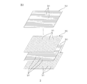
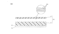
- FIG. 1 shows a side sectional view of a first embodiment of a reinforcing sheet of the present invention.
- FIG. 2 is an exploded perspective view of the surface layer shown in FIG.
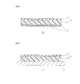
- FIG. 3A is an explanatory view for explaining an embodiment of a method for producing a reinforcing member of the present invention, and shows a step of attaching the reinforcing sheet shown in FIG. 1 to a metal plate.
- FIG. 3B shows a step of curing the adhesive layer and, if necessary, the core resin and the surface layer resin, following FIG. 3A.
- FIG. 4A is an explanatory view for explaining another embodiment of the method for manufacturing a reinforcing member of the present invention, and shows a step of forming an adhesive layer on a metal plate.
- FIG. 4A is an explanatory view for explaining another embodiment of the method for manufacturing a reinforcing member of the present invention, and shows a step of forming an adhesive layer on a metal plate.
- FIG. 4B shows the process of affixing a core material layer to an adhesive bond layer following FIG. 4A.
- FIG. 4C shows a step of attaching the surface layer to the core layer, following FIG. 4B.
- FIG. 5A shows a side cross-sectional view of a second embodiment of the reinforcing sheet of the present invention.
- FIG. 5B shows a state in which the reinforcing sheet shown in FIG. 5A is adhered to a metal plate.
- FIG. 6 shows a side cross-sectional view of one embodiment of a reinforcement kit of the present invention.
- FIG. 7A shows a metallurgical microscope image (magnification: 50 times) of the core material layer cross section in Example 1.
- FIG. 7B shows a state in which the metallurgical microscope image shown in FIG.
- FIG. 7A is binarized by image analysis software.
- FIG. 7C shows a metallurgical microscope image (magnification: 50 times) of the core material layer cross section in Example 5.
- FIG. 7D shows a state in which the metallographic image shown in FIG. 7C is binarized by image analysis software.
- FIG. 8A shows a metallographic image (magnification: 50 times) of the cross section of the core layer of Comparative Example 1.
- FIG. 8B shows a state in which the metallographic image shown in FIG. 8A is binarized by image analysis software.
- FIG. 8C shows a metallographic image (magnification: 50 times) of the cross section of the core layer of Comparative Example 2.
- FIG. 8D shows a state in which the metallographic image shown in FIG.
- FIG. 8C is binarized by image analysis software.
- 9A shows a SEM image (magnification: 20000 ⁇ ) of the core material layer cross section in Example 1.
- FIG. 9B shows a state in which the SEM image shown in FIG. 9A is binarized by image analysis software.
- 9C shows a SEM image (magnification: 20000 times) of the core material layer cross section in Example 2.
- FIG. 9D shows a state in which the SEM image shown in FIG. 9C is binarized by image analysis software.
- FIG. 10A shows a SEM image (magnification: 20000 ⁇ ) of the core material layer cross section in Example 3.
- FIG. 10B shows a state in which the SEM image shown in FIG. 10A is binarized by image analysis software.
- FIG. 10C shows a SEM image (magnification: 1000 times) of a core material layer cross section in Example 4.
- FIG. 10D shows a state in which the SEM image shown in FIG. 10C is binarized by image analysis software.
- FIG. 10E shows a SEM image (magnification: 1000 times) of the core material layer cross section in Example 5.
- FIG. 10F shows a state in which the SEM image shown in FIG. 10E is binarized by image analysis software.
- reinforcing sheet 1 which is a first embodiment of a reinforcing sheet of the present invention will be described with reference to FIGS. 1 and 2.
- the reinforcing sheet 1 has a flat plate shape, specifically, has a predetermined thickness, extends in a predetermined direction orthogonal to the thickness direction, and has a flat surface and a flat back surface. doing.
- the vertical direction in the drawing is the thickness direction of the reinforcing sheet 1.
- the upper side of the drawing is one side in the thickness direction, and the lower side of the drawing is the other side in the thickness direction.
- the left-right direction in the drawing is the first surface direction of the reinforcing sheet 1 (direction orthogonal to the thickness direction).
- the right side in the drawing is one side in the first surface direction, and the left side in the drawing is the other side in the first surface direction.
- the paper thickness direction is a second surface direction of the reinforcing sheet 1 (a direction orthogonal to both the thickness direction and the first surface direction).
- the front side in the drawing is one side in the second surface direction, and the back side in the drawing is the other side in the second surface direction.
- the reinforcing sheet 1 is a member adhered to the metal plate 6 to reinforce the metal plate 6 (see FIG. 3B).
- the reinforcing sheet 1 includes a core layer 2, a surface layer 3 disposed on one side in the thickness direction of the core layer 2, and an adhesive layer 4 disposed on the other side in the thickness direction of the core layer 2. That is, the adhesive layer 4, the core layer 2 and the surface layer 3 are laminated in order from the other side in the thickness direction toward the one side. Further, preferably, the release layer 5 is attached to the adhesive layer 4 in a peelable manner.
- the reinforcing sheet 1 in which the releasing layer 5 is attached to the adhesive layer 4 is distinguished from the reinforcing sheet 1 not having the releasing layer 5 as the releasing sheet with a releasing layer 1A.
- the core layer 2 is disposed between the surface layer 3 and the adhesive layer 4.
- the core layer 2 has a thin layer shape, specifically, has a predetermined thickness, extends in a predetermined direction orthogonal to the thickness direction, and has a flat surface (one surface in the thickness direction) and a flat back surface (thickness) The other side).
- the core layer 2 contains at least a resin. In addition, below, let resin which the core layer 2 contains be core resin.
- the core resin includes, for example, a matrix resin and an elastomer.
- the core resin preferably comprises a matrix resin and an elastomer.
- the core resin has a two-phase structure (phase separation structure) including a matrix resin constituting a medium, and a domain made of an elastomer and dispersed in the matrix resin.
- phase separation structure including a matrix resin constituting a medium, and a domain made of an elastomer and dispersed in the matrix resin.
- a first schematic configuration view enlarging a portion (encircled portion) of the core layer 2 and the surface layer 3 and a further enlarged view of the core resin (portion enclosed by a square) in the first schematic configuration view 2 shows a schematic configuration diagram.
- core resin is shown as core resin 21 and filler is shown as filler 20.
- filler 20 is shown as filler 20.
- a matrix resin is shown as a matrix resin 22
- domains made of elastomer are shown as domains 23
- voids (voids) are shown as voids 24.
- the matrix resin 22 constitutes a three-dimensionally continuous continuous phase
- the domain 23 composed of an elastomer constitutes a dispersed phase dispersed in the matrix resin 22 by phase separation from the matrix resin 22.
- Such a two-phase structure is also called a sea-island structure.
- the shape of the domain 23 is not particularly limited. Examples of the shape of the domain 23 include particulate (indeterminate), spherical, rod-like, and plate-like.
- the maximum length (maximum dimension) of the domain 23 is, for example, 500 ⁇ m or less, preferably 250 ⁇ m or less, more preferably 100 ⁇ m or less, particularly preferably 25 ⁇ m or less, for example 0.01 ⁇ m or more, preferably 0.05 ⁇ m
- the thickness is more preferably 0.1 ⁇ m or more. The dimensions of the domain can be measured according to the method described in the examples described later.
- the matrix resin is a hard resin having a higher Young's modulus than an elastomer described later.
- Young's modulus of the matrix resin is, for example, 1 MPa or more, preferably 5 MPa or more, more preferably 150 MPa or more, particularly preferably 1,200 MPa or more, particularly preferably 1, More than 500 MPa, for example, 10,000 MPa or less, preferably 5,000 MPa or less.
- a "solidified state” shows that a resin is cooled to less than a softening temperature, and is a solid state which does not have fluidity
- a resin is a thermosetting resin
- Young's modulus can be calculated by following formula (1) using the result measured by the following tension test (following same).
- Tensile test A sample having a size of 10 mm wide ⁇ 100 mm long is cut out from the solidified matrix resin. Then, the minimum thickness of the central portion of the sample is measured. The samples are then measured under the following test conditions. Test conditions: distance between grippers 50 mm, tensile speed 1 mm / min, room temperature 23 ° C.
- ⁇ F load increase (0.1 ⁇ 0.4 mm displacement)
- S cross sectional area (thickness ⁇ width)
- L initial length (50 mm)
- ⁇ L increase in length.
- thermoplastic resin As a matrix resin, a thermoplastic resin, a thermosetting resin, etc. are mentioned, for example.
- thermoplastic resin for example, polyolefin resin, polycarbonate resin, polyacetal resin, polyamide resin, polyphenylene ether resin, polybutylene terephthalate resin, polyphenylene sulfide resin, thermoplastic polyimide resin, polyether ether ketone resin, thermoplastic urethane resin, polyether An imide resin, a fluororesin, a liquid crystal polymer etc. are mentioned.
- thermosetting resin examples include epoxy resin, thermosetting polyimide resin, thermosetting urethane resin, unsaturated polyester, melamine resin, urea resin, phenol resin, alkyd resin, polysulfide resin, benzoxazine resin and the like.
- thermosetting resins are mentioned, and more preferably, epoxy resins are mentioned.
- the epoxy resin suitably used for the matrix resin is not modified by, for example, a modifier (e.g., a rubber modifier described later).
- a modifier e.g., a rubber modifier described later.
- the non-modified epoxy resin is distinguished as a non-modified epoxy resin from a modified epoxy resin (for example, a rubber-modified epoxy resin described later).
- non-modified epoxy resin specifically, bisphenol epoxy resin (eg, bisphenol A epoxy resin, bisphenol F epoxy resin, bisphenol S epoxy resin, hydrogenated bisphenol A epoxy resin, etc.), novolac epoxy resin (Eg, phenol novolac epoxy resin, cresol novolac epoxy resin, etc.), aromatic epoxy resin (eg, biphenyl epoxy resin, naphthalene epoxy resin, etc.), nitrogen-containing cyclic epoxy resin (eg, triglycidyl isocyanurate, Hydantoin epoxy resin and the like), alicyclic epoxy resin (for example, dicyclo cyclic epoxy resin and the like), glycidyl ether type epoxy resin, aliphatic epoxy resin and the like.
- bisphenol epoxy resin eg, bisphenol A epoxy resin, bisphenol F epoxy resin, bisphenol S epoxy resin, hydrogenated bisphenol A epoxy resin, etc.
- novolac epoxy resin Eg, phenol novolac epoxy resin, cresol novolac epoxy resin, etc.
- aromatic epoxy resin eg, bi
- unmodified epoxy resins preferably, bisphenol-type epoxy resins are mentioned, and more preferably, bisphenol A-type epoxy resins are mentioned.
- the epoxy equivalent of the unmodified epoxy resin in the uncured state (A stage) is, for example, 80 g / eq. Or more, preferably 100 g / eq. For example, 1000 g / eq. Or less, preferably, 800 g / eq. Or less, more preferably, 600 g / eq. Or less, particularly preferably 300 g / eq. It is below.
- the epoxy equivalent can be measured in accordance with JIS K 7236: 2001 (the same applies hereinafter).
- a commercial item can be used for such an unmodified epoxy resin.
- unmodified epoxy resin for example, trade name: JER 828 (epoxy equivalent 184 g / eq to 194 g / eq, manufactured by Mitsubishi Chemical Corporation), trade name: JER 834 (epoxy equivalent 230 g / eq to 270 g / eq, Mitsubishi Brand name: JER 1001 (epoxy equivalent 450 g / eq to 500 g / eq, manufactured by Mitsubishi Chemical Co., Ltd.), trade name: YD-115 (epoxy equivalent 180 g / eq to 194 g / eq, Nippon Steel Chemical Co., Ltd.) ), Trade name: YD-134 (epoxy equivalent 220 g / eq to 270 g / eq, manufactured by Nippon Steel Chemical Co., Ltd.), trade name: YD-011 (epoxy equivalent 440 g / eq
- Such matrix resins can be used alone or in combination of two or more.
- the content ratio of the matrix resin in the core material resin is, for example, 20% by mass or more, preferably 30% by mass or more, for example, 95% by mass or less, preferably 85% by mass or less, more preferably 60% by mass or less .
- the curing state of the thermosetting resin is not particularly limited, and is not cured (A stage), semi-cured (B stage) and completely cured (C stage) It may be either.
- the cured state of the thermosetting resin is preferably an uncured state or a semi-cured state More preferably, it is in an uncured state.
- the elastomer is a soft resin having a Young's modulus lower than that of the matrix resin, and acts as a toughness imparting agent that imparts toughness to the core layer 2 in a solidified state.
- the Young's modulus of the elastomer is, for example, 0.1 MPa or more, preferably 0.5 MPa or more, for example, 3,000 MPa or less, preferably 1,500 MPa or less, more preferably 1 Or less, particularly preferably 500 MPa or less, particularly preferably 100 MPa or less.
- elastomer examples include rubber, core-shell rubber particles, rubber-modified epoxy resin, thermoplastic elastomer and the like.
- the rubber is a thermosetting soft resin such as natural rubber, diene rubber (eg, acrylonitrile-butadiene rubber (NBR), methyl methacrylate-butadiene-styrene rubber (MBS), styrene-butadiene rubber, isoprene rubber Butadiene rubber, etc., non-diene rubber (eg, ethylene-propylene rubber, butyl rubber, silicone rubber, urethane rubber etc.) and the like.
- diene rubber eg, acrylonitrile-butadiene rubber (NBR), methyl methacrylate-butadiene-styrene rubber (MBS), styrene-butadiene rubber, isoprene rubber Butadiene rubber, etc.
- non-diene rubber eg, ethylene-propylene rubber, butyl rubber, silicone rubber, urethane rubber etc.
- the Mooney viscosity (ML1 + 4, at 100 ° C.) of the rubber is, for example, 10 or more, preferably 20 or more, for example, 80 or less, preferably 60 or less.
- a shell portion comprising an acrylic polymer and containing the core portion.
- the content ratio of the rubber in the core-shell rubber particles is, for example, 10% by mass or more, preferably 20% by mass or more, for example, 99% by mass or less, preferably 90% by mass or less.
- a commercial item can be used for such a core shell type rubber particle.
- Examples of commercially available products of core-shell rubber particles include Zefiac F 351 (manufactured by Aika Kogyo Co., Ltd.), Metabrene C 223 A (manufactured by Mitsubishi Chemical Co., Ltd.), and Kane Ace MX 136 (manufactured by Kaneka Co., Ltd.).
- the rubber-modified epoxy resin is an epoxy resin containing a rubber component, and the above-mentioned unmodified epoxy resin (preferably, a bisphenol-type epoxy resin, more preferably, a bisphenol A-type epoxy resin and / or a bisphenol F-type epoxy resin) And the reaction product with the rubber modifier.
- the above-mentioned unmodified epoxy resin preferably, a bisphenol-type epoxy resin, more preferably, a bisphenol A-type epoxy resin and / or a bisphenol F-type epoxy resin
- the rubber modifier is, for example, a modifier in which a functional group (eg, a carboxyl group or the like) capable of reacting with an epoxy group is introduced into the above-described rubber.
- a functional group eg, a carboxyl group or the like
- Specific examples of the rubber modifier include carboxyl group-terminated butadiene-acrylonitrile rubber (CTBN) and amine group-terminated butadiene-acrylonitrile rubber (ATBN).
- CTBN carboxyl group-terminated butadiene-acrylonitrile rubber
- ATBN amine group-terminated butadiene-acrylonitrile rubber
- the rubber modifiers can be used alone or in combination of two or more.
- CTBN is mentioned. That is, as a rubber
- a rubber-modified epoxy resin for example, the above-mentioned unmodified epoxy resin and the above-mentioned rubber modifier are mixed, and a catalyst is optionally added to react (denature) at, for example, 100 ° C to 180 ° C. .
- a catalyst is optionally added to react (denature) at, for example, 100 ° C to 180 ° C. .
- the functional group of the rubber modifier reacts with the epoxy group to prepare a rubber modified epoxy resin.
- the content ratio of the rubber component in the rubber modified epoxy resin is, for example, 5% by mass or more, preferably 15% by mass or more, for example, 80% by mass or less, preferably 50% by mass or less.
- the epoxy equivalent of the rubber-modified epoxy resin in the uncured state (A stage) is, for example, 80 g / eq. Or more, preferably 200 g / eq. For example, 10000 g / eq. Or less, preferably, 2000 g / eq. It is below.
- a commercial item can be used for such rubber-modified epoxy resin.
- rubber modified epoxy resin for example, trade name: EPR 1415-1 (liquid CTBN modified epoxy resin, epoxy equivalent 400 g / eq, manufactured by ADEKA), trade name: EPR 2000 (liquid CTBN modified epoxy resin, epoxy equivalent 215 g /) eq, manufactured by ADEKA), trade name: HypoxRK84L (solid CTBN modified epoxy resin, epoxy equivalent 1200 to 1800 g / eq, CVC Specialty Chemicals), trade name: Hypox RA 840 (liquid CTBN modified epoxy resin, epoxy equivalent 350 g / eq, CVC Specialty Chemicals) and the like.
- the cured state of the rubber-modified epoxy resin is not particularly limited, and the uncured state (A stage), semi-cured state (B stage) and fully cured state (C stage) It may be any.
- the cured state of the rubber-modified epoxy resin is preferably an uncured state or a semi-cured state More preferably, it is in an uncured state.
- thermoplastic elastomer is a thermoplastic soft resin, and examples thereof include olefin elastomers, styrene elastomers, and vinyl chloride elastomers.
- Such elastomers can be used alone or in combination of two or more.
- At least one member selected from the group consisting of rubber, core-shell type rubber particles and rubber-modified epoxy resin is preferably mentioned, and more preferably rubber-modified epoxy resin is particularly preferable.
- CTBN-modified epoxy resin is particularly preferable.
- the content ratio of the elastomer in the core material resin is, for example, 5% by mass or more, preferably 15% by mass or more, more preferably 40% by mass or more, for example, 80% by mass or less, preferably 70% by mass or less.
- combinations of matrix resin and elastomer include combinations of unmodified epoxy resin and rubber-modified epoxy resin, combinations of unmodified epoxy resin and core-shell type rubber particles, and combinations of unmodified epoxy resin and rubber. More preferably, a combination of a non-modified epoxy resin and a rubber-modified epoxy resin is mentioned.
- the matrix resin preferably comprises a non-modified epoxy resin, and more preferably consists of a non-modified epoxy resin.
- the elastomer preferably comprises a rubber modified epoxy resin, more preferably consists of a rubber modified epoxy resin.
- the core material resin includes a combination of a non-modified epoxy resin and a rubber-modified epoxy resin, it is possible to surely improve the reinforcing property to the metal plate, and improve the maximum bending test force of the reinforcing member 10 (described later).
- the improvement of the maximum bending test force of the reinforcing member 10 (described later) at (for example, 23 ° C.) can be reliably achieved.
- the true density of such core resin is, for example, 0.7 g / cm 3 or more, preferably 1.0 g / cm 3 or more, for example, 3.0 g / cm 3 or less, preferably 2.0 g / cm 3. It is below.
- the core layer 2 further contains a filler as an optional component.
- the filler is a hard filler, for example, uniformly dispersed in the core layer 2 (see FIG. 1).
- the filler for example, calcium carbonate (eg, calcium carbonate, light calcium carbonate, white glaze etc.), calcium oxide, talc, mica, clay, mica powder, bentonite, silica (eg, hydrophobic silica etc.), alumina, Aluminum silicate, aluminum hydroxide, titanium oxide, barium titanate, ferrite, carbon black, acetylene black, aluminum powder, glass powder, hollow glass (glass balloon), chopped strand (eg, glass fiber, carbon fiber, aramid fiber, etc.) Etc.
- the fillers may be used alone or in combination of two or more.
- fillers preferably, calcium carbonate and hollow glass are mentioned, and more preferably, hollow glass is mentioned.
- the average particle size of the filler is, for example, 1 ⁇ m or more, preferably 10 ⁇ m or more, for example, 100 ⁇ m or less, preferably 50 ⁇ m or less.
- the true density of the filler is, for example, 0.3 g / cm 3 or more, preferably 0.5 g / cm 3 or more, for example, 10 g / cm 3 or less, preferably 5.0 g / cm 3 or less.
- the content ratio of the filler is, for example, 10 parts by mass or more, preferably 30 parts by mass or more, more preferably 50 parts by mass or more, for example, 500 parts by mass or less, preferably 100 parts by mass with respect to 100 parts by mass of the core material resin. It is 350 parts by mass or less, more preferably 100 parts by mass or less, and particularly preferably 80 parts by mass or less.
- the content ratio (volume ratio) of the filler in the core layer 2 is, for example, 1% by volume or more, preferably 2% by volume or more, more preferably 7% by volume or more, still more preferably 9% by volume or more, particularly preferably Is at least 10% by volume, particularly preferably at least 16% by volume, more preferably at least 20% by volume, still more preferably at least 26% by volume, particularly preferably at least 30% by volume, even more particularly preferably Is 40 vol% or more, most preferably 46 vol% or more, for example, 95 vol% or less, preferably 92 vol% or less, more preferably 89 vol% or less, still more preferably 86 vol% or less, particularly Preferably, it is 82% by volume or less, particularly preferably 80% by volume or less.
- the content ratio (mass ratio) of the filler in the core layer 2 is, for example, 5% by mass or more, preferably 15% by mass or more, more preferably 30% by mass or more, for example, less than 85% by mass, preferably 80 It is at most mass%, more preferably at most 75 mass%, particularly preferably at most 70 mass%.
- the content ratio (volume ratio, mass ratio) of the filler in the core material layer 2 is the above lower limit or more, the Young's modulus of the core material layer 2 can be adjusted to a suitable range (described later), and the maximum bending of the reinforcing member 10 (described later) It is possible to improve the test force, particularly the maximum bending test force of the reinforcing member 10 (described later) in a high temperature range (for example, 80 ° C. or more). If the content ratio (volume ratio, mass ratio) of the filler in the core layer 2 is equal to or less than the above upper limit, the filler can be uniformly dispersed in the core layer 2, and the core layer 2 can be stably formed. it can.
- the core material layer 2 preferably further contains a latent curing agent as an optional component.
- a thermosetting resin for example, unmodified epoxy resin, rubber-modified epoxy resin, etc.
- the latent curing agent is solid at room temperature (23 ° C.) and cures the core resin at a predetermined temperature.
- the latent curing agent has activity at, for example, 80 ° C. or more and 200 ° C. or less.
- a latent hardening agent As a latent hardening agent, a urea system compound, an amine system compound, an acid anhydride system compound, an amide system compound, a cyano compound, a dihydrazide system compound, an imidazole system compound, an imidazoline system compound etc. are mentioned, for example.
- urea compounds examples include 3- (3,4-dichlorophenyl) -1,1-dimethylurea (DCMU), N′-phenyl-N, N-dimethylurea, 1,1 ′-(methyl-m-phenylene And the like, etc.) and the like.
- amine compound examples include ethylenediamine, propylenediamine, diethylenetriamine, triethylenetetramine, amine adducts thereof, metaphenylenediamine, diaminodiphenylmethane, diaminodiphenyl sulfone and the like.
- acid anhydride compounds include phthalic anhydride, maleic anhydride, tetrahydrophthalic anhydride, dodecenyl succinic anhydride, dichlorosuccinic anhydride, benzophenone tetracarboxylic acid anhydride, chlorendic anhydride and the like Be
- polyamide As an amide system compound, polyamide etc. are mentioned, for example.
- cyano compounds examples include dicyandiamide and the like.
- hydrazide compounds include dihydrazides such as adipic acid dihydrazide.
- imidazole compounds include methylimidazole, 2-ethyl-4-methylimidazole, ethylimidazole, isopropylimidazole, 2,4-dimethylimidazole, phenylimidazole, undecylimidazole, heptadecylimidazole, 2-phenyl-4-methyl Imidazole etc. are mentioned.
- imidazoline compounds include methyl imidazoline, 2-ethyl-4-methyl imidazoline, ethyl imidazoline, isopropyl imidazoline, 2,4-dimethyl imidazoline, phenyl imidazoline, undecyl imidazoline, heptadecyl imidazoline, 2-phenyl-4-methyl An imidazoline etc. are mentioned.
- the latent curing agent can be used alone or in combination of two or more.
- urea compounds and cyano compounds preferred are urea compounds and cyano compounds, more preferably combinations of urea compounds and cyano compounds, and particularly preferably combinations of DCMU and dicyandiamide Be
- the content ratio of the latent curing agent is, for example, 0.5 parts by mass or more, preferably 1 part by mass or more, for example, 30 parts by mass or less, preferably 20 parts by mass or less, with respect to 100 parts by mass of the core resin. More preferably, it is 15 parts by mass or less.
- the core layer 2 may contain, as an optional component, a tackifier (for example, a rosin resin, a terpene resin, a coumarone indene resin, a petroleum resin, etc.), a lubricant (for example, stearic acid) as needed.
- a tackifier for example, a rosin resin, a terpene resin, a coumarone indene resin, a petroleum resin, etc.
- a lubricant for example, stearic acid
- known additives such as stabilizers, anti-aging agents, antioxidants, ultraviolet light absorbers, colorants, flame retardants, antistatic agents, conductivity-imparting agents, slidability-imparting agents, surfactants, etc. It can also be added at a rate of
- the thickness of the core layer 2 is, for example, 0.1 mm or more, preferably 1 mm or more, for example, 20 mm or less, preferably 10 mm or less, and more preferably 6 mm or less.
- the ratio of the thickness of the core layer 2 to the thickness of the surface layer 3 is, for example, 0.1 or more, preferably 1 or more, more preferably 5 or more, for example, 50 or less, preferably 40 or less, more preferably 20 It is below.
- the Young's modulus of the core layer 2 is, for example, 600 MPa or more, preferably 1000 MPa or more, for example, 7000 MPa or less, when the core resin is in a solidified state.
- Such core layer 2 is free of voids 24 or contains a plurality of voids 24 (see FIG. 1).
- the area ratio of the voids 24 in the cross section of the solidified material of the core layer 2 is 50% or less, preferably 45% or less, more preferably 40% or less, particularly preferably 35% or less, particularly preferably 30% or less
- it is 0% or more, preferably 1% or more, more preferably 5% or more, particularly preferably 10% or more, particularly preferably 15% or more.
- the area ratio of a void can be measured based on the method as described in an Example (following same).
- the maximum bending test force of the reinforcing member 10 (described later) is improved, particularly the maximum bending test of the reinforcing member 10 (described later) in high temperature range The power can be improved.
- the area ratio of the void 24 is the above lower limit or more, the improvement of the maximum bending test force of the reinforcing member 10 (described later), in particular, the improvement of the maximum bending test force of the reinforcing member 10 (described later) at room temperature (for example, 23 ° C.) Can be That is, the compression failure or interfacial shear failure of the core layer 2 can be suppressed.
- the number of cross-sectional area 10624Myuemu 2 per elastomer domains 23 of solid of the core layer 2 is, for example, 3 or more, preferably, 5 or more, for example, 100,000 or less, preferably, is 50,000 or less .
- the number of domains per unit cross-sectional area can be measured based on the method described in the Examples (the same applies hereinafter).
- the number of cross-sectional area 26.56Myuemu 2 per elastomer domains 23 of solid of the core layer 2 is, for example, 1 or more, preferably 5 or more, for example, 250 or less, preferably 125 or less.
- the improvement of the maximum bending test force of the reinforcing member 10 (described later), particularly the improvement of the maximum bending test force of the reinforcing member 10 (described later) at room temperature (for example, 23 ° C.) Can be assured. If the number of domains per unit cross-sectional area is equal to or less than the upper limit, it is possible to improve the maximum bending test force of the reinforcing member 10 (described later) particularly in a high temperature range (for example, 80 ° C. or more).
- the area ratio of the elastomer domain 23 in the cross section of the solidified material of the core layer 2 is, for example, 3% or more, preferably 5% or more, more preferably 10% or more, for example 50% or less, preferably 40% or less, more preferably 30% or less.
- the area ratio of a domain can be measured based on the method as described in an Example (following same).
- the improvement of the maximum bending test force of the reinforcing member 10 (described later), in particular, the improvement of the maximum bending test force of the reinforcing member 10 (described later) at room temperature Can be
- the surface layer 3 is disposed on the surface (one surface in the thickness direction) of the core layer 2.
- the surface layer 3 has a thin layer shape, specifically, has a predetermined thickness, extends in a predetermined direction orthogonal to the thickness direction, and has a flat surface and a flat back surface.
- the size of the surface layer 3 is the same as that of the core layer 2, but the size of the surface layer 3 is not limited thereto.
- the surface layer 3 may be smaller than the core layer 2 in the surface direction of the reinforcing sheet 1.
- the surface layer 3 a plurality of unidirectional fiber resin composite sheets 30 are stacked (see a first schematic configuration view in FIG. 1).
- the surface layer 3 preferably comprises a plurality of unidirectional fiber resin composite sheets 30.
- Each of the plurality of unidirectional fiber resin composite sheets 30 contains a plurality of fibers and a resin.
- Each unidirectional fiber resin composite sheet 30 is formed by impregnating a fiber base made of a plurality of fibers with a resin. In addition, below, let resin which the unidirectional fiber resin composite sheet 30 contains be surface layer resin.
- each of the plurality of fibers 31 extends in the same direction (hereinafter, referred to as a fiber direction) orthogonal to the thickness direction in each unidirectional fiber resin composite sheet 30.
- the plurality of fibers 31 are arranged in a direction orthogonal to the fiber direction so as to be substantially parallel to one another in each unidirectional fiber resin composite sheet 30.
- each of the plurality of unidirectional fiber resin composite sheets preferably contains carbon fibers or glass fibers. Also, all of the plurality of unidirectional fiber resin composite sheets preferably contain fibers of the same type.
- fibers preferably, carbon fibers are mentioned. If the plurality of fibers contain carbon fibers, it is possible to more reliably improve the reinforcing property of the reinforcing sheet 1 with respect to the metal plate.
- the mass per unit area of a plurality of fibers in each unidirectional fiber resin composite sheet is, for example, 10 g / m 2 or more, preferably 80 g / m 2 or more, for example, 2000 g / m 2 or less, preferably , 1000 g / m 2 or less.
- the surface layer resin is impregnated in the plurality of fibers 31.
- surface layer resin is not specifically limited, For example, above-mentioned thermosetting resin etc. are mentioned.
- the surface layer resin can be used singly or in combination of two or more types in each unidirectional fiber resin composite sheet, and preferably used alone.
- all of the plurality of unidirectional fiber resin composite sheets preferably contain the same kind of surface layer resin.
- epoxy resins preferred are epoxy resins.
- an epoxy resin used for surface layer resin the thing similar to the epoxy resin (unmodified epoxy resin) used for core material resin is mentioned, for example.
- the epoxy resins can be used alone or in combination of two or more.
- the curing state of the thermosetting resin is not particularly limited, and any of uncured state (A stage), semi-cured state (B stage) and completely cured state (C stage) It may be On the other hand, in the state before reinforcement sheet 1 is used for reinforcement of metal plate 6 (for example, reinforcement sheet 1A with a release layer), the hardening state of thermosetting resin is preferably an unhardened state.
- the content ratio (resin content ratio) of the surface layer resin in each unidirectional fiber resin composite sheet 30 is, for example, 10% by mass or more, preferably 20% by mass or more, for example, 60% by mass or less, preferably 40% by mass or less It is.
- each unidirectional fiber resin composite sheet 30 preferably contains the above-mentioned latent curing agent at an appropriate ratio as an optional component.
- the tensile strength per one layer of such a unidirectional fiber resin composite sheet 30 is, for example, 100 MPa or more, preferably 300 MPa or more, when the fiber direction is oriented in the tensile direction and the surface layer resin is in a cured state. For example, 7000 MPa or less.
- tensile strength measures the maximum test force (maximum value of load in a tensile test) of the sample (unidirectional fiber resin composite sheet) based on the above-mentioned tensile test, and the maximum test force is the cross-sectional area of the sample ( It can be calculated by dividing by thickness ⁇ width) (the same applies hereinafter).
- each unidirectional fiber resin composite sheet 30 is not less than the above lower limit, it is possible to more reliably improve the reinforcing property of the reinforcing sheet 1 to the metal plate, and the maximum bending test of the reinforcing member 10 (described later) It is possible to more surely improve the power.
- each unidirectional fiber resin composite sheet 30 is, for example, 0.01 mm or more, preferably 0.05 mm or more, for example, 0.5 mm or less, preferably 0.3 mm or less.
- a commercial item can be used for such a unidirectional fiber resin composite sheet 30.
- a commercial item of the unidirectional fiber resin composite sheet 30 for example, trade name: P3252S-10 (fiber basis weight 100 g / m 2 , resin content 33 mass%, manufactured by Toray Industries, Inc.), trade name: P3255-25 (fiber basis 250 g) / M 2 , resin content 24 mass%, manufactured by Toray Industries, trade name: P17045G-12 (fiber basis weight 125 g / m 2 , resin content 24 mass%, manufactured by Toray Industries, Inc.) trade name: TR395G100S (fiber gross weight 100 g / M 2 , resin content 33% by mass, manufactured by Mitsubishi Chemical Co., Ltd., trade name: TR380G250S (fiber basis weight 250 g / m 2 , resin content 33% by mass, manufactured by Mitsubishi Chemical Corp.), trade name: TRH 350C125S (fiber basis weight 125 g) / M 2 , resin content 25% by mass, manufactured by Mitsubishi
- the plurality of unidirectional fiber resin composite sheets 30 are stacked in the thickness direction of the reinforcing sheet 1, and are stacked such that the fiber directions of the unidirectional fiber resin composite sheets 30 adjacent to each other intersect (for example, orthogonally). Ru.
- the number (the number of laminations) of the plurality of unidirectional fiber resin composite sheets 30 is, for example, two or more, preferably three or more, for example, less than ten.
- the reinforcing property of the reinforcing sheet 1 with respect to the metal plate can be secured. If the number (the number of laminations) of the plurality of unidirectional fiber resin composite sheets 30 is equal to or less than the upper limit, the number of laminations of the plurality of unidirectional fiber resin composite sheets 30 can be reduced, and the manufacturing cost of the surface layer 3 can be reduced. it can.
- the thickness of the surface layer 3 is, for example, 0.02 mm or more, preferably 0.15 mm or more, for example, 5 mm or less, preferably 1 mm or less, and more preferably 0.5 mm or less.
- the adhesive layer 4 is disposed on the back surface (the other surface in the thickness direction) of the core layer 2.
- the adhesive layer 4 has a thin layer shape, specifically, has a predetermined thickness, extends in a predetermined direction orthogonal to the thickness direction, and has a flat surface and a flat back surface.
- the adhesive layer 4 is formed of, for example, a known adhesive or a double-sided adhesive tape.
- the adhesive forming the adhesive layer 4 is in the form of a paste, and examples thereof include an epoxy-based adhesive, a urethane-based adhesive, and an acrylic-based adhesive.
- the adhesive may be used alone or in combination of two or more.
- the double-sided adhesive tape for forming the adhesive layer 4 includes, for example, a substrate and the above-described adhesive laminated on both sides of the substrate.
- Examples of the double-sided adhesive tape for forming the adhesive layer 4 include a thermosetting double-sided adhesive tape NA590 manufactured by Nitto Denko Corporation.
- the adhesive layer 4 is preferably formed of a double-sided adhesive tape.
- the thickness of the adhesive layer 4 is, for example, 0.05 mm or more, preferably 0.1 mm or more, for example, 1 mm or less, preferably 0.5 mm or less.
- the release layer 5 is located on the opposite side of the core layer 2 with respect to the adhesive layer 4.
- the release layer 5 is peelably attached to the surface of the adhesive layer 4 in order to protect the adhesive layer 4 until the reinforcing sheet 1 is used to form the reinforcing member 10 (described later).
- the release layer 5 is laminated on the surface of the adhesive layer 4 so as to cover the surface of the adhesive layer 4 at the time of shipment, conveyance and storage of the reinforcing sheet 1, and immediately before using the reinforcing sheet 1, It is a flexible layer which can be peeled off from the surface of the adhesive layer 4 so as to be curved in a substantially U-shape.
- the adhesion surface of the release layer 5 is subjected to release treatment as necessary.
- the material of the releasing layer 5 is, for example, a resin such as polyester (for example, polyethylene terephthalate (PET) or the like), polyolefin (for example, polyethylene, polypropylene or the like), or fluorine resin (for example, polytetrafluoroethylene (PTFE) or the like) Materials, resin-coated paper, etc. may be mentioned, and preferably polyethylene terephthalate is mentioned.
- the release layer 5 may not be attached to the adhesive layer 4. In this case, the adhesive layer 4 of the reinforcing sheet 1 is exposed.
- the method of manufacturing the reinforcing sheet 1 includes a core material preparation step of preparing the core material layer 2, a surface layer preparation step of preparing the surface layer 3, a bonding step of bonding the surface layer 3 to one side in the thickness direction of the core material layer 2, and a core material layer. And an adhesive layer forming step of forming the adhesive layer 4 on the other side in the thickness direction of 2.
- the core material preparation step first, the above-mentioned content ratio of the above-mentioned matrix resin, the above-mentioned elastomer and, if necessary, the above-mentioned optional components (filler, latent curing agent and additive) The mixture is kneaded to prepare a resin composition (kneaded product).
- a resin composition kneaded product
- the above-mentioned matrix resin contains a thermosetting resin is explained in full detail.
- thermosetting resin contained in the matrix resin is preferably in an uncured state.
- the elastomer contains a rubber, preferably, a veil-like (block-like) rubber is kneaded and added to the matrix resin.
- the elastomer contains core-shell type rubber particles, preferably, powdery core-shell type rubber particles are added to the matrix resin.
- the elastomer contains a rubber-modified epoxy resin
- a matrix resin is added to the uncured rubber-modified epoxy resin.
- the matrix resin is added to the pellet-like thermoplastic elastomer.
- each component is not particularly limited, and examples thereof include kneading using a mixing roll.
- kneading of each component is preferably carried out under vacuum degassing.
- the kneading time is, for example, 1 minute or more, preferably 5 minutes or more, for example, 60 minutes or less, preferably 30 minutes or less, and more preferably 15 minutes or less.
- each component can be sufficiently kneaded, and if the kneading time is equal to or less than the above upper limit, the area ratio of the voids 24 in the cross section of the solidified material of the core layer 2 is in the above range. It can be adjusted surely.
- the kneading temperature is, for example, room temperature (23 ° C.) or more, preferably 80 ° C. or more, more preferably 100 ° C. or more, for example, less than 150 ° C., preferably 130 ° C. or less.
- the kneading temperature is less than the temperature at which the latent curing agent substantially reacts. If the temperature is lower than the temperature at which the latent curing agent substantially reacts, the kneading temperature may be heated to exceed room temperature (23 ° C.).
- the area ratio of the voids 24 in the cross section of the solidified material of the core layer 2 can be adjusted to the above-mentioned range.
- the resin composition is then sandwiched between two release papers and rolled, for example, by press molding.
- the core layer 2 is thus prepared between the two release papers.
- the core resin contains a thermosetting resin (matrix resin) and / or a rubber-modified epoxy resin (elastomer), they are preferably in an uncured state.
- the preparation of the core layer 2 is completed without heating the core layer 2.
- the core layer 2 is heated, The core resin is semi-cured or completely cured.
- the heating temperature of the core layer 2 is equal to or higher than the temperature at which the latent curing agent substantially reacts, and is, for example, 80 ° C. or more, preferably 150 ° C. or more, for example, 250 ° C. or less.
- the matrix resin contains a thermoplastic resin
- the matrix resin for example, a pellet-like thermoplastic resin
- an elastomer for example, powder-like rubber, powder-like core-shell rubber particles, powder-like
- a cured product of a rubber-modified epoxy resin, a thermoplastic elastomer in the form of pellets, etc., and, if necessary, the above-mentioned optional components (filler and additive) are melt-kneaded to the above content ratio, and the resin
- the composition is, for example, extruded into a sheet.
- the core material layer 2 containing a thermoplastic resin can be prepared.
- a plurality of unidirectional fiber resin composite sheets 30 are prepared.
- a plurality of unidirectional fiber resin composite sheets 30 are laminated in the thickness direction such that the fiber directions of the unidirectional fiber resin composite sheets 30 adjacent to each other intersect (for example, orthogonally).
- the plurality of laminated unidirectional fiber resin composite sheets 30 are pressed so as to be sandwiched from the outside in the thickness direction.
- the surface layer 3 is prepared.
- the sticking step as shown in FIG. 1, first, two release papers are peeled off from the core layer 2. Then, the surface layer 3 is disposed on the surface of the core layer 2 (one surface in the thickness direction), and the surface layer 3 is pressed toward the core layer 2 as necessary.
- the surface layer 3 is thereby attached to the core layer 2.
- the adhesive layer 4 when the adhesive layer 4 is formed of an adhesive, the adhesive is applied to the back surface (the other surface in the thickness direction) of the core layer 2 by a known method. Moreover, when the adhesive bond layer 4 is formed from a double-sided adhesive tape, a double-sided adhesive tape is affixed on the back surface (other surface of the thickness direction) of the core material layer 2.
- the adhesive layer 4 is formed on the back surface (the other surface in the thickness direction) of the core layer 2.
- the reinforcement sheet 1 provided is manufactured (prepared).
- the release layer 5 is attached to the adhesive layer 4 as necessary.
- the release layer-provided reinforcing sheet 1A is manufactured.
- the metal plate 6 is a metal plate used for various industrial products, and is not particularly limited.
- a metal plate used for a transport machine for example, a pillar, a roof, a fender, a hood, a trunk, a quarter panel, a door, a door handle, a door mirror, etc. of an automobile
- a metal plate used for home appliances Preferably, a metal plate used for a transport machine is mentioned.
- the metal plate 6 has flat plate shape for convenience, the shape in particular of the metal plate 6 is not restrict
- Examples of the shape of the metal plate 6 include a flat plate shape and a cylindrical shape (for example, a cylindrical shape, a square cylindrical shape, and the like).
- the exposed adhesive layer 4 is applied to the surface of the metal plate 6. paste. Thereby, the reinforcing sheet 1 is disposed on the metal plate 6.
- positioned is heated, and the adhesive bond layer 4 is hardened.
- the heating temperature is, for example, 80 ° C. or more, preferably 150 ° C. or more, for example, 250 ° C. or less.
- the heating time is, for example, 5 minutes or more, preferably 10 minutes or more, for example, 80 minutes or less, preferably 60 minutes or less.
- the heating temperature is set to a temperature at which the latent curing agent substantially reacts, and the thermosetting resin in the uncured state is Cure at the same time (make it completely cured).
- the latent curing agent is substantially heated to the above heating temperature.
- the temperature is set to a temperature higher than the temperature at which the thermosetting resin reacts and the thermosetting resin in the uncured state and / or the rubber-modified epoxy resin in the uncured state are simultaneously cured (taken into a completely cured state).
- the reinforcing sheet 1 is bonded to the metal plate 6 to reinforce the metal plate 6.
- the reinforcement member 10 provided with the reinforcement sheet 1 and the metal plate 6 reinforced by the reinforcement sheet 1 is manufactured.
- the curing state of the thermosetting resin and / or the rubber-modified epoxy resin is Preferably, they differ from each other before and after use of the reinforcing sheet 1.
- thermosetting resin and / or the rubber-modified epoxy resin is preferably in an uncured or semi-cured state
- the thermosetting resin and / or the rubber-modified epoxy resin is preferably in a completely cured state.
- the reinforcement sheet 1 before use (for example, reinforcement sheet 1A with a release layer) and the reinforcement sheet 1 in the reinforcement member 10 have the same structure except the cured state of said resin.
- the range of the area ratio of the void 24 in the cross section of the solidified material (completely cured product) of the core material layer 2, the cross-sectional area 10624 ⁇ m 2 of the solidified material (completely cured product) of the core material layer 2 In the range of the number of domains 23, the range of the number of elastomer domains 23 per 26.56 ⁇ m 2 of the cross section 26.56 ⁇ m 2 of the solidified material of the core layer 2 (completely cured product), and of the solidified material of the core layer 2 (completely cured product)
- Each of the range of the area ratio of the elastomeric domain 23 in the cross section is the same as the above-mentioned range.
- the maximum bending test force at room temperature (23 ° C.) of the reinforcing member 10 is, for example, 400 N or more, preferably 500 N or more, and more preferably 600 N or more.
- the maximum bending test force can be measured based on the method as described in the Example (same below).
- the maximum bending test force at 100 ° C. of the reinforcing member 10 is, for example, 150 N or more, preferably 200 N or more, and more preferably 300 N or more.
- the reinforcing member 10 can also be manufactured by sequentially laminating the adhesive layer 4, the core layer 2 and the surface layer 3 on the metal plate 6.
- the adhesive layer 4 is formed on the metal plate 6.
- the core layer 2 is disposed on the surface of the adhesive layer 4 opposite to the metal plate 6, and if necessary, the core layer 2 is pressed toward the adhesive layer 4 . Thereby, the core layer 2 is attached to the surface of the adhesive layer 4 opposite to the metal plate 6. In other words, the core layer 2 is attached to the metal plate 6 by the adhesive layer 4.
- the surface layer 3 is disposed on the surface of the core layer 2 opposite to the metal plate 6, and the surface layer 3 is pressed toward the core layer 2 as necessary. Thus, the surface layer 3 is attached to the surface of the core layer 2 opposite to the metal plate 6.
- the reinforcing sheet 1 including the adhesive layer 4, the core layer 2, and the surface layer 3 is disposed on the metal plate 6.
- positioned is heated similarly to the above, and the adhesive agent layer 4 and core resin and surface layer resin are hardened as needed.
- the reinforcing sheet 1 is adhered to the metal plate 6 to reinforce the metal plate 6. Also, the reinforcing member 10 is manufactured.
- the reinforcing sheet 1 is provided with a surface layer 3 on which a plurality of unidirectional fiber resin composite sheets 30 are laminated, and when the surface layer 3 is externally applied to the reinforcing member 10 , The largest tensile stress is placed on the surface of the core layer 2. Therefore, compared with the case where the surface layer 3 is formed of glass cloth, the reinforcing property of the reinforcing sheet 1 to the metal plate 6 can be improved.
- the reinforcing sheet 1 for the metal plate 6 is Sufficient reinforcement of the
- the number (the number of laminations) of the plurality of unidirectional fiber resin composite sheets 30 is increased, the process of laminating them increases, and the process (preparation) of the surface layer 3 becomes complicated. There is a drawback that the manufacturing cost is increased.
- the reinforcing sheet 1 includes the core layer 2 in which the area ratio of the voids 24 in the cross section of the solidified product is less than the upper limit, the number of the plurality of unidirectional fiber resin composite sheets 30 provided in the surface layer 3 Of the reinforcing sheet 1 with respect to the metal plate 6 can be sufficiently secured.
- the strength of the reinforcing member 10 can be reduced while the manufacturing cost can be reduced. Specifically, the maximum bending test force etc. can be improved.
- the core material resin 21 preferably includes a matrix resin 22 and an elastomer forming a two-phase structure dispersed in the matrix resin 22, and a domain consisting of an elastomer per 10624 ⁇ m 2 of the cross-sectional area of the solidified material of the core material layer 2
- the number of 23 is the above lower limit or more, more preferably, the number of the domains 23 composed of elastomer per cross section 26.56 ⁇ m 2 of the solidified material of the core layer 2 is above the above lower limit.
- the domains 23 can be reliably dispersed in the core resin 21, and the improvement of the maximum bending test force of the reinforcing member 10, in particular, the improvement of the maximum bending test force of the reinforcing member 10 at room temperature (for example, 23 ° C.) is assured.
- room temperature for example, 23 ° C.
- the area ratio of the domain 23 in the cross section of the solidified material of the core layer 2 is preferably less than or equal to the above upper limit.
- the maximum bending test force of the reinforcing member 10 in particular, the maximum bending test force of the reinforcing member 10 at room temperature (for example, 23 ° C.).
- the matrix resin preferably comprises a non-modified epoxy core resin
- the elastomer preferably comprises a rubber modified epoxy core resin
- the affinity between the matrix resin and the elastomer can be improved, and the maximum bending test force of the reinforcing member 10, particularly the maximum bending test force of the reinforcing member 10 at room temperature (for example, 23 ° C.) is further improved. It is possible to plan more reliably.
- the core layer 2 further contains a filler 20.
- the content rate of filler 20 in core material layer 2 is preferably more than the above-mentioned lower limit. Therefore, the Young's modulus of the core layer 2 can be adjusted to a suitable range, and the strength of the reinforcing member 10 can be improved, in particular, the strength of the reinforcing member 10 in a high temperature range (for example, 80 ° C. or more) can be improved.
- the content rate of the filler 20 in the core layer 2 is preferably less than the above-mentioned upper limit. Therefore, the filler can be uniformly dispersed in the core layer 2, and the core layer 2 can be stably formed.
- the reinforcing sheet 1 further includes an adhesive layer 4 disposed on the other side in the thickness direction of the core layer 2. Therefore, the reinforcing sheet 1 can be reliably bonded to the metal plate 6.
- Each unidirectional fiber resin composite sheet 30 preferably contains carbon fibers or glass fibers and a thermosetting resin. Therefore, the reinforcing property of the reinforcing sheet 1 with respect to the metal plate 6 can be more reliably improved, and the strength of the reinforcing member 10 can be more reliably improved.
- the reinforcing member 10 includes a reinforcing sheet 1 and a metal plate 6 reinforced by the reinforcing sheet 1. Therefore, the strength of the reinforcing member 10 can be improved.
- the reinforcing sheet 1 is manufactured by a simple method of attaching the surface layer 3 to the core layer 2. Therefore, the reinforcing sheet 1 can be manufactured smoothly.
- the reinforcing member 10 attaches the reinforcing sheet 1 to the metal plate 6, or as shown in FIGS. 4A to 4C, after attaching the core layer 2 to the metal plate 6, It is manufactured by the simple method of bonding the surface layer 3 to the layer 2. Therefore, the reinforcing member 10 can be manufactured smoothly.
- the reinforcing sheet 1 is provided with the adhesive layer 4 as shown in FIG. 1, the reinforcing sheet of the present invention may not have the adhesive layer.
- the reinforcing sheet 7 does not have the adhesive layer 4 but has the core layer 2 and the surface layer 3, and preferably comprises the core layer 2 and the surface layer 3.
- the core layer 2 preferably has surface tackiness.
- the release layer 5 is attached so as to be removable.
- the reinforcement sheet 7 by which the release layer 5 is stuck to the core material layer 2 is distinguished from the reinforcement sheet 7 which does not have the release layer 5 as a reinforcement sheet 7A with release layer.
- the release layer 5 may not be attached to the core layer 2. In this case, the other surface in the thickness direction of the core layer 2 is exposed.
- the exposed core layer 2 is attached to the surface of the metal plate 6. .
- the reinforcing sheet 7 is disposed on the metal plate 6.
- the metal plate 6 on which the reinforcing sheet 7 is disposed is heated as described above to cure the core resin and the surface layer resin.
- the reinforcing sheet 7 is bonded to the metal plate 6 to reinforce the metal plate 6.
- the reinforcement member 11 provided with the reinforcement sheet 7 and the metal plate 6 reinforced by the reinforcement sheet 7 is manufactured.
- the reinforcing member 11 can also be manufactured by sequentially laminating the core layer 2 and the surface layer 3 on the metal plate 6.
- the core layer 2 and the surface layer 3 are integrally attached to each other, but in the reinforcing kit 8, as shown in FIG. 6, the core layer 2 and the surface layer 3 Are separated from each other.
- the reinforcing kit 8 includes the core layer 2 and the surface layer 3 which are separate from each other. Further, also in the reinforcing kit 8, the adhesive layer 4 may be formed on the back surface (the other surface in the thickness direction) of the core layer 2 as indicated by a phantom line. The release layer 5 may be attached to the adhesive layer 4 in a peelable manner as indicated by phantom lines.
- the reinforcement kit 8 is a kit adhered to the metal plate 6 to reinforce the metal plate 6, and the core layer 2 and the surface layer 3 are simultaneously distributed and sold as one package and used simultaneously.
- the core layer 2 is attached to the metal plate 6, and then the surface layer 3 is attached to the surface of the core layer 2 opposite to the metal plate 6.
- the core material resin and the surface layer resin are cured by heating as described above as necessary.
- Each of the range of the area ratio of the domain 23 in the cross-section of is the same as the range described above.
- the reinforcing kit 8 is bonded to the metal plate 6 to reinforce the metal plate 6. Therefore, also in such a reinforcement kit 8, the same function and effect as those of the first embodiment can be exhibited.
- the surface layer 3 is disposed on the surface (one surface in the thickness direction) of the core layer 2, and the adhesive layer 4 is disposed on the back surface (the other surface in the thickness direction) of the core layer 2.
- the reinforcing sheet of the present invention is not limited thereto.
- a substrate can be arranged between the surface layer 3 and the core layer 2 and / or between the adhesive layer 4 and the core layer 2.
- a base material for example, glass cloth, carbon cloth, synthetic resin non-woven fabric (for example, polypropylene resin non-woven fabric, polyethylene resin non-woven fabric, ester resin non-woven fabric, etc.), metal foil, short carbon fiber, short fiber glass fiber, polyester film Etc.
- an adhesive layer configured similarly to the adhesive layer 4 can be disposed between the surface layer 3 and the core layer 2.
- first embodiment, the second embodiment and the modification can be combined as appropriate.
- Examples 1 to 5 Preparation of surface layer A plurality of carbon fibers (CFUD, fiber weight 100 g / m 2 ) aligned in a direction perpendicular to the fiber direction so as to be substantially parallel to each other and epoxy impregnated with a plurality of carbon fibers
- the number shown in Table 1 was prepared as a unidirectional fiber resin composite sheet (made by Toray Industries, thickness 0.10 mm) comprising a resin (surface layer resin, content ratio 33% by mass).
- the tensile strength of each unidirectional fiber resin composite sheet was 2500 MPa when the surface layer resin was in a cured state.
- a plurality of unidirectional fiber resin composite sheets were laminated such that the fiber directions of the unidirectional fiber resin composite sheets adjacent to each other were orthogonal to each other. Thereafter, a plurality of unidirectional fiber resin composite sheets were pressed from the outside in the thickness direction to prepare a surface layer.
- Preparation of core material layer A resin composition was prepared by kneading the matrix resin, the elastomer, the filler, and the latent curing agent according to the formulation shown in Table 1 by a mixing roll.
- the kneading time was 5 minutes, and the kneading temperature was 120.degree.
- the resin composition was sandwiched between two release papers and rolled by press molding to prepare a core layer having a thickness shown in Table 1.
- the core resin in the core layer was in an uncured state. Further, the Young's modulus of the core layer when the core resin is in a cured state is shown in Table 1.
- a kneaded product thermosetting resin composition
- an epoxy resin, a rubber-modified epoxy resin, a filler, and a toughness imparting agent are kneaded by a mixing roll heated to 120 ° C., and then the kneaded product is cooled to 60 to 100 ° C., Furthermore, a latent curing agent was added, and the mixture was kneaded by a mixing roll to obtain a kneaded product.
- Bisphenol A type epoxy resin (trade name: Epicoat (registered trademark) # 834, epoxy equivalent 270 g / eq., Manufactured by Mitsubishi Chemical Corporation) ... 50 parts by mass, Liquid CTBN modified epoxy resin (trade name: EPR 1415-1, epoxy equivalent 400 g / eq., Manufactured by ADEKA) ...
- Solid CTBN modified epoxy resin (trade name: Hypox RK 84L, epoxy equivalent 1200 to 1800 g / eq., CVC Specialty Chemicals) 15 parts by mass
- Urea-based compound: 3- (3,4-dichlorophenyl) -1,1-dimethylurea (trade name: DCMU, manufactured by Hodogaya Chemical Co., Ltd.) 2 parts by mass
- Dicyandiamide (trade name: DDA-50, manufactured by CVC Specialty Chemicals) ...
- Hydrophobic silica Dimethyl silicone oil surface treated silica (trade name: AEROJIL RY 200, average particle diameter 12 ⁇ m, manufactured by Nippon Aerosil Co., Ltd.) 2 parts by mass
- Glass powder Glass powder (trade name: PF70E-001, specific gravity 2.58, average fiber length 10.5 ⁇ m, manufactured by Nittobo Co., Ltd.) 20 parts by mass
- the obtained kneaded material was sandwiched between release paper In the state, it was rolled to a thickness of 0.1 mm by press molding to form a thermosetting resin layer.
- thermosetting resin layer is peeled off, and the thermosetting resin layer is attached to both sides of a 130 ⁇ m thick non-woven fabric (trade name: 8004, Nissei Co., Ltd.) with a heat press (50 ° C)
- the double-sided adhesive tape was prepared by setting the total thickness of the thermosetting resin layer and the substrate to 0.2 mm.
- the double-sided adhesive tape was arrange
- a double-sided adhesive tape was attached to the core layer to form an adhesive layer.
- the reinforcement sheet provided with the core material layer, the surface layer, and the adhesive bond layer was manufactured.
- Example 1 A reinforcing sheet was produced in the same manner as in Example 1 except that the kneading time of the resin composition in preparation of the core layer was changed to 30 minutes.
- FIG. 7A A metallographic image (magnification: 50 times) of the core layer cross section of Example 1 is shown in FIG. 7A, and a metallographic image of the core layer cross section after Example 1 after binarization is shown in FIG. 7B.
- FIG. 7C A metallographic image (magnification: 50 times) of the core layer cross section of Example 5 is shown in FIG. 7C, and a metallographic image of the core layer cross section after binarization of Example 5 is shown in FIG. 7D.
- FIG. 8A A metallographic image (magnification: 50 times) of the core layer cross section of Comparative Example 1 is shown in FIG. 8A, and a metallographic image of the core layer cross section after Comparative Example 1 after binarization is shown in FIG. 8B.
- FIG. 8C A metallographic image (magnification: 50 times) of the core layer cross section of Comparative Example 2 is shown in FIG. 8C, and a metallographic image of the core layer cross section after Comparative Example 2 after binarization is shown in FIG. 8D.
- the elastomer was then stained with osmium tetroxide in the cross section of each core layer.
- the SEM is based on observation at 20,000 times (observation area: 26.56 ⁇ m 2 ), and when the number of domains of the elastomer does not exceed 5 at 20,000 times observation, 1000 times (observation area: 10) , 6234 ⁇ m 2 ).
- observation place the place where the area of the filler occupied in the observation area is the smallest is selected.
- the SEM image (magnification: 20,000 times) of the core material layer cross section of Example 1 is shown in FIG. 9A, and the SEM image after binarization of the core material layer cross section of Example 1 is shown in FIG. 9B.
- the SEM image (magnification: 20,000 times) of the core material layer cross section of Example 2 is shown in FIG. 9C, and the SEM image after binarization of the core material layer cross section of Example 2 is shown in FIG. 9D.
- the SEM image (magnification: 20,000 times) of the core material layer cross section of Example 3 is shown to FIG. 10A, and the SEM image after binarization of the core material layer cross section of Example 3 is shown to FIG. 10B.
- the SEM image (magnification: 1000 times) of the core material layer cross section of Example 4 is shown to FIG. 10C, and the SEM image after binarization of the core material layer cross section of Example 4 is shown to FIG. 10D.
- the SEM image (magnification: 1000 times) of the core material layer cross section of Example 5 is shown to FIG. 10E, and the SEM image after binarization of the core material layer cross section of Example 5 is shown to FIG. 10F.
- the area ratio of the domain in the cross section of the cured product of the core layer and the average size of the domain were calculated from the analysis result of the SEM image of each core layer cross section.
- the results are shown in Table 1.
- the elliptical approximation of the domain was not possible.
- each reinforcing sheet was placed on the metal plate.
- each reinforcing sheet was adhered to the metal plate.
- the maximum bending test force at room temperature (23 ° C.) is less than 400 N.
- the maximum bending test force at room temperature (23 ° C.) is 400N or more and less than 500N.
- the maximum bending test force at room temperature (23 ° C.) is 500N or more and less than 600N.
- the maximum bending test force at room temperature (23 ° C.) is 600 N or more.
- the maximum bending test force at 100 ° C. is less than 150 N.
- the maximum bending test force at 100 ° C. is 150 N or more and less than 200 N.
- the maximum bending test force at 100 ° C. is 200 N or more and less than 300 N.
- the maximum bending test force at 100 ° C. is 300 N or more.
- the thickness (sum of the thickness of the metal plate, adhesive, core resin and surface layer resin) of the sample after the bending strength test at each temperature is shown in Table 1 as thickness (after curing) .
- JER 828 unmodified epoxy resin, uncured, epoxy equivalent 184 g / eq to 194 g / eq, manufactured by Mitsubishi Chemical Corporation
- JER 834 unmodified epoxy resin, uncured state, epoxy equivalent 230 g / eq to 270 g / eq, manufactured by Mitsubishi Chemical Corporation
- EPR 2000 CTBN modified epoxy resin, uncured, epoxy equivalent 215 g / eq, manufactured by ADEKA
- Hypox RA 840 CTBN modified epoxy resin, uncured, epoxy equivalent 350 g / eq, manufactured by CVC Specialty Chemicals
- Hypox RK 84 L CTBN modified epoxy resin, uncured, epoxy equivalent 1200 to 1800 g / eq, manufactured by CVC Specialty Chemicals
- Zefiac F 351 Core-shell rubber particles (core NBR, shell acrylic polymer), manufactured by Aika Kogyo Co., Ltd.
- Metabrene C223A Core-shell rubber particles (core part MBS, shell part acrylic polymer), manufactured by Mitsubishi Chemical Corporation, Tuffden 2003: rubber, Mooney viscosity (ML1 + 4, at 100 ° C) 33, bale shape, manufactured by Asahi Kasei, Krynac 3345F: rubber, Mooney viscosity (ML1 + 4, at 100 ° C.) 45 ⁇ 5, bale shape, manufactured by Lanxess, CaCO 3 : Heavy calcium carbonate, true density 2.7 g / cm 3 , Maruo Calcium Co., Ltd., S-60HS: hollow glass, average particle diameter 30 ⁇ m, true density 0.6 g / cm 3 , 3M company, DCMU-99: Urea-based compound, 3- (3,4-dichlorophenyl) -1,1-dimethylurea, manufactured by Hodogaya Chemical Co., Ltd. DDA-50: dicyandiamide, manufactured by CVC Specialty Chemicals, NT-N: manufactured by Ei
- the reinforcing sheet and the reinforcing kit of the present invention can be applied to the reinforcement of metal plates used in various industrial products, for example, suitable for reinforcement of metal plates used in transport machines, metal plates used in home appliances, etc.
- Used for The reinforcing member of the present invention can be applied to various industrial products, and is suitably used, for example, in transport machines, home appliances, and the like.
Landscapes
- Engineering & Computer Science (AREA)
- Textile Engineering (AREA)
- Laminated Bodies (AREA)
- Reinforced Plastic Materials (AREA)
Abstract
補強シートは、金属板に接着して前記金属板を補強するための補強シートであって、樹脂を含有する心材層と、前記心材層の厚み方向の一方側に配置される表層と、を備え、前記表層は、複数の一方向繊維樹脂複合シートが積層されており、前記心材層の固化物の断面におけるボイドの面積比率が、50%以下である。
Description
本発明は、補強シート、補強部材、補強キット、補強シートの製造方法および補強部材の製造方法に関する。
従来、各種産業製品に使用される金属板を、補強シートにより補強することが知られている。
そのような補強シートとして、例えば、ガラスクロスと、ガラスクロスに積層される熱硬化性樹脂層とを備える鋼板補強シートが提案されている(例えば、特許文献1参照。)。
そのような補強シートは、熱硬化性樹脂層を鋼板に貼り付けた後、熱硬化性樹脂層を加熱硬化させることによって、鋼板を補強する。
しかるに、近年、各種産業製品に使用される金属板の薄肉化が望まれている。特に自動車などの輸送機械では、二酸化炭素の排出量を削減すべく、金属板の薄肉化を図り、輸送機械の軽量化を図ることが望まれている。
しかし、金属板を薄肉化すると強度が不十分となる場合がある。そこで、特許文献1に記載の鋼板補強シートを用いて金属板を補強することが検討されるが、輸送機械などの各種産業製品では、特許文献1に記載の鋼板補強シートの金属板に対する補強性のさらなる向上が要求される場合がある。
そこで、本発明は、金属板に対する補強性の向上を図ることができる補強シート、補強部材、補強キット、補強シートの製造方法および補強部材の製造方法を提供する。
本発明[1]は、金属板に接着して前記金属板を補強するための補強シートであって、樹脂を含有する心材層と、前記心材層の厚み方向の一方側に配置される表層と、を備え、前記表層は、複数の一方向繊維樹脂複合シートが積層されており、前記心材層の固化物の断面におけるボイドの面積比率が、50%以下である補強シートを含んでいる。
本発明[2]は、前記心材層は、充填材をさらに含有し、前記心材層における前記充填材の含有割合は、15質量%以上85質量%未満である、上記[1]に記載の補強シートを含んでいる。
本発明[3]は、前記樹脂は、マトリックス樹脂と、前記マトリックス樹脂中に分散する二相構造を形成するエラストマーとを含み、前記心材層の固化物の断面における前記エラストマーからなるドメインの面積比率が、40%以下である、上記[1]または[2]に記載の補強シートを含んでいる。
本発明[4]は、前記樹脂は、マトリックス樹脂と、前記マトリックス樹脂中に分散する二相構造を形成するエラストマーとを含み、前記心材層の固化物の断面における前記エラストマーからなるドメインの面積比率が、30%以下である、上記[1]または[2]に記載の補強シートを含んでいる。
本発明[5]は、前記心材層の固化物の断面積10624μm2あたりの前記ドメインの数が5以上である、上記[3]または[4]に記載の補強シートを含んでいる。
本発明[6]は、前記心材層の固化物の断面積26.56μm2あたりの前記ドメインの数が5以上である、上記[3]または[4]に記載の補強シートを含んでいる。
本発明[7]は、前記マトリックス樹脂は、未変性エポキシ樹脂を含み、前記エラストマーは、ゴム変性エポキシ樹脂を含む、上記[3]~[6]のいずれか一項に記載の補強シートを含んでいる。
本発明[8]は、前記心材層の厚み方向の他方側に配置される接着剤層をさらに備える、上記[1]~[7]のいずれか一項に記載の補強シートを含んでいる。
本発明[9]は、前記複数の一方向繊維樹脂複合シートのそれぞれは、カーボン繊維またはガラス繊維と、熱硬化性樹脂とを含有する、上記[1]~[8]のいずれか一項に記載の補強シートを含んでいる。
本発明[10]は、上記[1]~[9]のいずれか一項に記載の補強シートと、前記補強シートにより補強される金属板と、を備える、補強部材を含んでいる。
本発明[11]は、金属板に接着して前記金属板を補強するための補強キットであって、樹脂を含有する心材層と、複数の一方向繊維樹脂複合シートが積層されている表層と、を備え、前記心材層の固化物の断面におけるボイドの面積が、50%以下である、補強キットを含んでいる。
本発明[12]は、金属板に接着して前記金属板を補強するための補強シートの製造方法であって、樹脂を含有する心材層であって、前記心材層の固化物の断面におけるボイドの面積比率が50%以下である心材層を準備する工程と、複数の一方向繊維樹脂複合シートが積層されている表層を準備する工程と、前記表層を前記心材層の厚み方向の一方側に貼り付ける工程と、を含む、補強シートの製造方法を含んでいる。
本発明[13]は、樹脂を含有する心材層であって、前記心材層の固化物の断面におけるボイドの面積比率が50%以下である心材層と、前記心材層の厚み方向の一方側に配置され、複数の一方向繊維樹脂複合シートが積層されている表層と、を備える補強シートを準備する工程と、前記補強シートを金属板に貼り付けて、前記金属板を補強する工程と、を含む、補強部材の製造方法を含んでいる。
本発明[14]は、樹脂を含有する心材層であって、前記心材層の固化物の断面におけるボイドの面積比率が50%以下である心材層を、金属板に貼り付ける工程と、前記心材層における前記金属板と反対側の面に、複数の一方向繊維樹脂複合シートが積層されている表層を貼り付けて、前記金属板を補強する工程と、を含む、補強部材の製造方法を含んでいる。
本発明の補強シートおよび補強キットは、複数の一方向繊維樹脂複合シートが積層されている表層を備え、かつ、心材層の固化物の断面におけるボイドの面積比率が上記上限以下である。そのため、金属板に対する補強シートおよび補強キットの補強性の向上を図ることができ、補強シートまたは補強キットにより補強される金属板(補強部材)の強度の向上を図ることができる。
本発明の補強部材は、上記の補強シートと、補強シートにより補強される金属板とを備える。そのため、補強部材の強度の向上を図ることができる。
本発明の補強シートの製造方法は、表層を心材層に貼り付けて、上記の補強シートを製造する。そのため、簡易な方法でありながら、上記の補強シートを円滑に製造することができる。
本発明の補強部材の製造方法は、金属板に上記の補強シートを貼り付けるか、または、金属板に心材層を貼り付けた後、心材層に表層を貼り付けて、上記の補強部材を製造する。そのため、簡易な方法でありながら、上記の補強部材を円滑に製造することができる。
<第1実施形態>
1.補強シート
本発明の補強シートの第1実施形態である補強シート1を、図1および図2を参照して説明する。
1.補強シート
本発明の補強シートの第1実施形態である補強シート1を、図1および図2を参照して説明する。
図1に示すように、補強シート1は、平板形状を有し、具体的には、所定の厚みを有し、前記厚み方向と直交する所定方向に延び、平坦な表面および平坦な裏面を有している。
図1において、紙面上下方向は、補強シート1の厚み方向である。紙面上側は、厚み方向の一方側であり、紙面下側は、厚み方向の他方側である。
図1において、紙面左右方向は、補強シート1の第1の面方向(厚み方向に直交する方向)である。紙面右側は、第1の面方向の一方側であり、紙面左側は、第1の面方向の他方側である。
図1において、紙厚方向は、補強シート1の第2の面方向(厚み方向および第1の面方向の両方向と直交する方向)である。紙面手前側は、第2の面方向の一方側であり、紙面奥側は、第2の面方向の他方側である。
補強シート1は、金属板6に接着して金属板6を補強するための部材である(図3B参照)。補強シート1は、心材層2と、心材層2の厚み方向の一方側に配置される表層3と、心材層2の厚み方向の他方側に配置される接着剤層4とを備える。つまり、接着剤層4、心材層2および表層3は、厚み方向の他方側から一方側に向かって順に積層されている。また、接着剤層4には、好ましくは、離型層5が剥離可能に貼着されている。離型層5が接着剤層4に貼着される補強シート1を、離型層付補強シート1Aとして、離型層5を有さない補強シート1と区別する。
心材層2は、表層3と接着剤層4との間に配置される。心材層2は、薄層形状を有し、具体的には、所定の厚みを有し、前記厚み方向と直交する所定方向に延び、平坦な表面(厚み方向一方面)および平坦な裏面(厚み方向他方面)を有している。心材層2は、少なくとも樹脂を含有する。なお、以下において、心材層2が含有する樹脂を心材樹脂とする。
心材樹脂は、例えば、マトリックス樹脂と、エラストマーとを含む。心材樹脂は、好ましくは、マトリックス樹脂およびエラストマーからなる。
心材樹脂は、媒体を構成するマトリックス樹脂と、エラストマーからなり、マトリックス樹脂中に分散するドメインとを含む二相構造(相分離構造)を有する。
図1において、心材層2および表層3の一部(円で囲んだ部分)を拡大した第1概略構成図と、第1概略構成図における心材樹脂(四角で囲んだ部分)をさらに拡大した第2概略構成図とを示す。第1概略構成図において、心材樹脂を心材樹脂21として示し、充填材を充填材20として示す。第2概略構成図において、マトリックス樹脂をマトリックス樹脂22として示し、エラストマーからなるドメインをドメイン23として示し、ボイド(気孔)をボイド24として示す。
二相構造において、マトリックス樹脂22は、三次元的に連続する連続相を構成し、エラストマーからなるドメイン23は、マトリックス樹脂22から相分離して、マトリックス樹脂22中に分散する分散相を構成する。このような二相構造は、海島構造とも呼ばれる。
なお、ドメイン23の形状は、特に制限されない。ドメイン23の形状として、例えば、粒子状(不定形状)、球形状、棒状、板状などが挙げられる。ドメイン23の最大長さ(最大寸法)は、例えば、500μm以下、好ましくは、250μm以下、さらに好ましくは、100μm以下、とりわけ好ましくは、25μm以下、例えば、0.01μm以上、好ましくは、0.05μm以上、さらに好ましくは、0.1μm以上である。ドメインの寸法は、後述する実施例に記載の方法に準拠して測定できる。
マトリックス樹脂は、後述するエラストマーよりも高いヤング率を有する硬質樹脂である。マトリックス樹脂のヤング率は、マトリックス樹脂が固化状態であるときに、例えば、1MPa以上、好ましくは、5MPa以上、さらに好ましくは、150MPa以上、とりわけ好ましくは、1,200MPa以上、特に好ましくは、1,500MPaを超過し、例えば、10,000MPa以下、好ましくは、5,000MPa以下である。
なお、「固化状態」とは、樹脂が熱可塑性樹脂である場合、樹脂が軟化温度未満に冷却されて流動性を有さない固体状態であることを示し、樹脂が熱硬化性樹脂である場合、樹脂が完全硬化された状態(Cステージ)であることを示す。
また、ヤング率は、下記引張試験により測定される結果を用いて、下記式(1)により算出することができる(以下同様)。
引張試験:固化状態のマトリックス樹脂から、幅10mm×長さ100mmのサイズを有するサンプルを切り出す。そして、サンプルの中央部分の最小厚みを測定する。次いで、下記試験条件において、サンプルを測定する。
試験条件:掴み具間距離50mm、引張速度1mm/min、室温23℃
試験条件:掴み具間距離50mm、引張速度1mm/min、室温23℃

ΔF:荷重増加(0.1→0.4mm変位)、S:断面積(厚み×幅)、L:初期長さ(50mm)、ΔL:長さ増加分。
マトリックス樹脂として、例えば、熱可塑性樹脂、熱硬化性樹脂などが挙げられる。
熱可塑性樹脂として、例えば、ポリオレフィン樹脂、ポリカーボネート樹脂、ポリアセタール樹脂、ポリアミド樹脂、ポリフェニレンエーテル樹脂、ポリブチレンテレフタレート樹脂、ポリフェニレンサルファイド樹脂、熱可塑性ポリイミド樹脂、ポリエーテルエーテルケトン樹脂、熱可塑性ウレタン樹脂、ポリエーテルイミド樹脂、フッ素樹脂、液晶ポリマーなどが挙げられる。
熱硬化性樹脂として、例えば、エポキシ樹脂、熱硬化性ポリイミド樹脂、熱硬化性ウレタン樹脂、不飽和ポリエステル、メラミン樹脂、尿素樹脂、フェノール樹脂、アルキド樹脂、ポリサルファイド樹脂、ベンゾオキサジン樹脂などが挙げられる。
このようなマトリックス樹脂のなかでは、好ましくは、熱硬化性樹脂が挙げられ、さらに好ましくは、エポキシ樹脂が挙げられる。
マトリックス樹脂に好適に用いられるエポキシ樹脂は、例えば、変性剤(例えば、後述するゴム変性剤など)により変性されていない。以下、変性されていないエポキシ樹脂を、未変性エポキシ樹脂として、変性されたエポキシ樹脂(例えば、後述するゴム変性エポキシ樹脂など)と区別する。
未変性エポキシ樹脂として、具体的には、ビスフェノール型エポキシ樹脂(例えば、ビスフェノールA型エポキシ樹脂、ビスフェノールF型エポキシ樹脂、ビスフェノールS型エポキシ樹脂、水素添加ビスフェノールA型エポキシ樹脂など)、ノボラック型エポキシ樹脂(例えば、フェノールノボラック型エポキシ樹脂、クレゾールノボラック型エポキシ樹脂など)、芳香族系エポキシ樹脂(例えば、ビフェニル型エポキシ樹脂、ナフタレン型エポキシ樹脂など)、含窒素環エポキシ樹脂(例えば、トリグリシジルイソシアヌレート、ヒダントインエポキシ樹脂など)、脂環式エポキシ樹脂(例えば、ジシクロ環型エポキシ樹脂など)、グリシジルエーテル型エポキシ樹脂、脂肪族系エポキシ樹脂などが挙げられる。
未変性エポキシ樹脂のなかでは、好ましくは、ビスフェノール型エポキシ樹脂が挙げられ、さらに好ましくは、ビスフェノールA型エポキシ樹脂が挙げられる。
未硬化状態(Aステージ)における未変性エポキシ樹脂のエポキシ当量は、例えば、80g/eq.以上、好ましくは、100g/eq.以上、例えば、1000g/eq.以下、好ましくは、800g/eq.以下、さらに好ましくは、600g/eq.以下、とりわけ好ましくは、300g/eq.以下である。エポキシ当量は、JIS K7236:2001に準拠して測定できる(以下同様)。
このような未変性エポキシ樹脂は、市販品を用いることができる。未変性エポキシ樹脂の市販品として、例えば、商品名:JER 828(エポキシ当量184g/eq~194g/eq、三菱ケミカル社製)、商品名:JER 834(エポキシ当量230g/eq~270g/eq、三菱ケミカル社製)、商品名:JER 1001(エポキシ当量450g/eq~500g/eq、三菱ケミカル社製)、商品名:YD-115(エポキシ当量180g/eq~194g/eq、新日鐵化学社製)、商品名:YD-134(エポキシ当量220g/eq~270g/eq、新日鐵化学社製)、商品名:YD-011(エポキシ当量440g/eq~510g/eq、新日鐵化学社製)、商品名:EP-4100HF(エポキシ当量182g/eq、ADEKA社製)などが挙げられる。
このようなマトリックス樹脂は、単独使用または2種以上併用することができる。
心材樹脂におけるマトリックス樹脂の含有割合は、例えば、20質量%以上、好ましくは、30質量%以上、例えば、95質量%以下、好ましくは、85質量%以下、さらに好ましくは、60質量%以下である。
なお、マトリックス樹脂が熱硬化性樹脂を含む場合、熱硬化性樹脂の硬化状態は、特に制限されず、未硬化状態(Aステージ)、半硬化状態(Bステージ)および完全硬化状態(Cステージ)のいずれであってもよい。一方、補強シート1が金属板6の補強に使用される前の状態(例えば、離型層付補強シート1A)において、熱硬化性樹脂の硬化状態は、好ましくは、未硬化状態または半硬化状態であり、さらに好ましくは、未硬化状態である。
エラストマーは、マトリックス樹脂よりも低いヤング率を有する軟質樹脂であって、固化状態の心材層2に靱性を付与する靱性付与剤として作用する。エラストマーのヤング率は、エラストマーが固化状態であるときに、例えば、0.1MPa以上、好ましくは、0.5MPa以上、例えば、3,000MPa以下、好ましくは、1,500MPa以下、さらに好ましくは、1,000MPa以下、とりわけ好ましくは、500MPa以下、特に好ましくは、100MPa以下である。
エラストマーとして、例えば、ゴム、コアシェル型ゴム粒子、ゴム変性エポキシ樹脂、熱可塑性エラストマーなどが挙げられる。
ゴムは、熱硬化性の軟質樹脂であって、例えば、天然ゴム、ジエン系ゴム(例えば、アクリロニトリル-ブタジエンゴム(NBR)、メチルメタクリレート-ブタジエン-スチレンゴム(MBS)、スチレン-ブタジエンゴム、イソプレンゴム、ブタジエンゴムなど)、非ジエン系ゴム(例えば、エチレン-プロピレンゴム、ブチルゴム、シリコーンゴム、ウレタンゴムなど)などが挙げられる。
ゴムのムーニー粘度(ML1+4、at100℃)は、例えば、10以上、好ましくは、20以上、例えば、80以下、好ましくは、60以下である。
コアシェル型ゴム粒子は、実質的に上記したゴム(好ましくは、ジエン系ゴム、さらに好ましくは、NBRおよび/またはMBS)からなるコア部と、アクリル系ポリマーからなり、コア部を内包するシェル部とを備える。
コアシェル型ゴム粒子におけるゴムの含有割合は、例えば、10質量%以上、好ましくは、20質量%以上、例えば、99質量%以下、好ましくは、90質量%以下である。
このようなコアシェル型ゴム粒子は、市販品を用いることができる。コアシェル型ゴム粒子の市販品として、例えば、ゼフィアックF351(アイカ工業社製)、メタブレンC223A(三菱ケミカル社製)、カネエースMX136(カネカ社製)などが挙げられる。
ゴム変性エポキシ樹脂は、ゴム成分を含有するエポキシ樹脂であって、上記した未変性エポキシ樹脂(好ましくは、ビスフェノール型エポキシ樹脂、さらに好ましくは、ビスフェノールA型エポキシ樹脂および/またはビスフェノールF型エポキシ樹脂)と、ゴム変性剤との反応物である。
ゴム変性剤は、例えば、上記したゴムに、エポキシ基と反応可能な官能基(例えば、カルボキシル基など)が導入された変性剤である。ゴム変性剤として、具体的には、カルボキシル基末端ブタジエン-アクリロニトリルゴム(CTBN)、アミン基末端ブタジエン-アクリロニトリルゴム(ATBN)などが挙げられる。ゴム変性剤は、単独使用または2種以上併用することができる。
ゴム変性剤のなかでは、好ましくは、CTBNが挙げられる。つまり、ゴム変性エポキシ樹脂として、好ましくは、CTBNにより変性されたエポキシ樹脂(以下、CTBN変性エポキシ樹脂とする。)が挙げられる。
ゴム変性エポキシ樹脂を調製するには、例えば、上記した未変性エポキシ樹脂と上記したゴム変性剤とを混合し、必要により触媒を添加して、例えば、100℃~180℃において反応(変性)させる。これによって、ゴム変性剤の官能基とエポキシ基とが反応し、ゴム変性エポキシ樹脂が調製される。
ゴム変性エポキシ樹脂におけるゴム成分の含有割合は、例えば、5質量%以上、好ましくは、15質量%以上、例えば、80質量%以下、好ましくは、50質量%以下である。
未硬化状態(Aステージ)におけるゴム変性エポキシ樹脂のエポキシ当量は、例えば、80g/eq.以上、好ましくは、200g/eq.以上、例えば、10000g/eq.以下、好ましくは、2000g/eq.以下である。
このようなゴム変性エポキシ樹脂は、市販品を用いることができる。ゴム変性エポキシ樹脂の市販品として、例えば、商品名:EPR1415-1(液状CTBN変性エポキシ樹脂、エポキシ当量400g/eq、ADEKA社製)、商品名:EPR2000(液状CTBN変性エポキシ樹脂、エポキシ当量215g/eq、ADEKA社製)、商品名:HypoxRK84L(固形CTBN変性エポキシ樹脂、エポキシ当量1200~1800g/eq、CVC Specialty Chemicals社製)、商品名:HypoxRA840(液状CTBN変性エポキシ樹脂、エポキシ当量350g/eq、CVC Specialty Chemicals社製)などが挙げられる。
なお、エラストマーがゴム変性エポキシ樹脂を含む場合、ゴム変性エポキシ樹脂の硬化状態は、特に制限されず、未硬化状態(Aステージ)、半硬化状態(Bステージ)および完全硬化状態(Cステージ)のいずれであってもよい。一方、補強シート1が金属板6の補強に使用される前の状態(例えば、離型層付補強シート1A)において、ゴム変性エポキシ樹脂の硬化状態は、好ましくは、未硬化状態または半硬化状態であり、さらに好ましくは、未硬化状態である。
熱可塑性エラストマーは、熱可塑性の軟質樹脂であって、例えば、オレフィン系エラストマー、スチレン系エラストマー、塩化ビニル系エラストマーなどが挙げられる。
このようなエラストマーは、単独使用または2種以上併用することができる。
このようなエラストマーのなかでは、好ましくは、ゴム、コアシェル型ゴム粒子およびゴム変性エポキシ樹脂からなる群から選択される少なくとも1種が挙げられ、さらに好ましくは、ゴム変性エポキシ樹脂が挙げられ、とりわけ好ましくは、CTBN変性エポキシ樹脂が挙げられる。
心材樹脂におけるエラストマーの含有割合は、例えば、5質量%以上、好ましくは、15質量%以上、さらに好ましくは、40質量%以上、例えば、80質量%以下、好ましくは、70質量%以下である。
マトリックス樹脂とエラストマーとの組み合わせとして、好ましくは、未変性エポキシ樹脂とゴム変性エポキシ樹脂との組み合わせ、未変性エポキシ樹脂とコアシェル型ゴム粒子との組み合わせ、未変性エポキシ樹脂とゴムとの組み合わせが挙げられ、さらに好ましくは、未変性エポキシ樹脂とゴム変性エポキシ樹脂との組み合わせが挙げられる。
つまり、マトリックス樹脂は、好ましくは、未変性エポキシ樹脂を含み、さらに好ましくは、未変性エポキシ樹脂からなる。エラストマーは、好ましくは、ゴム変性エポキシ樹脂を含み、さらに好ましくは、ゴム変性エポキシ樹脂からなる。
心材樹脂が未変性エポキシ樹脂とゴム変性エポキシ樹脂との組み合わせを含むと、金属板に対する補強性の向上を確実に図ることができ、補強部材10(後述)の最大曲げ試験力の向上、特に室温(例えば、23℃)における補強部材10(後述)の最大曲げ試験力の向上を確実に図ることができる。
このような心材樹脂の真密度は、例えば、0.7g/cm3以上、好ましくは、1.0g/cm3以上、例えば、3.0g/cm3以下、好ましくは、2.0g/cm3以下である。
また、心材層2は、好ましくは、任意成分として充填材をさらに含有する。
充填材は、硬質充填材であって、例えば、心材層2に均一に分散される(図1参照)。充填材として、例えば、炭酸カルシウム(例えば、重質炭酸カルシウム、軽質炭酸カルシウム、白艶華など)、酸化カルシウム、タルク、マイカ、クレー、雲母粉、ベントナイト、シリカ(例えば、疎水性シリカなど)、アルミナ、アルミニウムシリケート、水酸化アルミニウム、酸化チタン、チタン酸バリウム、フェライト、カーボンブラック、アセチレンブラック、アルミニウム粉、ガラス粉、中空ガラス(ガラスバルーン)、チョップドストランド(例えば、ガラス繊維、カーボン繊維、アラミド繊維など)などが挙げられる。充填材は、単独使用または2種以上併用することができる。
充填材のなかでは、好ましくは、炭酸カルシウムおよび中空ガラスが挙げられ、さらに好ましくは、中空ガラスが挙げられる。
充填材の平均粒子径は、例えば、1μm以上、好ましくは、10μm以上、例えば、100μm以下、好ましくは、50μm以下である。
充填材の真密度は、例えば、0.3g/cm3以上、好ましくは、0.5g/cm3以上、例えば、10g/cm3以下、好ましくは、5.0g/cm3以下である。
充填材の含有割合は、心材樹脂100質量部に対して、例えば、10質量部以上、好ましくは、30質量部以上、さらに好ましくは、50質量部以上、例えば、500質量部以下、好ましくは、350質量部以下、さらに好ましくは、100質量部以下、とりわけ好ましくは、80質量部以下である。
心材層2における充填材の含有割合(体積割合)は、例えば、1体積%以上、好ましくは、2体積%以上、より好ましくは、7体積%以上、さらに好ましくは、9体積%以上、とりわけ好ましくは、10体積%以上、特に好ましくは、16体積%以上、より特に好ましくは、20体積%以上、さらに特に好ましくは、26体積%以上、とりわけ特に好ましくは、30体積%以上、より一層特に好ましくは、40体積%以上、最も好ましくは、46体積%以上、例えば、95体積%以下、好ましくは、92体積%以下、より好ましくは、89体積%以下、さらに好ましくは、86体積%以下、とりわけ好ましくは、82体積%以下、特に好ましくは、80体積%以下である。
心材層2における充填材の含有割合(質量割合)は、例えば、5質量%以上、好ましくは、15質量%以上、さらに好ましくは、30質量%以上、例えば、85質量%未満、好ましくは、80質量%以下、さらに好ましくは、75質量%以下、とりわけ好ましくは、70質量%未満である。
心材層2における充填材の含有割合(体積割合、質量割合)が上記下限以上であれば、心材層2のヤング率を好適な範囲(後述)に調整でき、補強部材10(後述)の最大曲げ試験力の向上、特に高温域(例えば、80℃以上)における補強部材10(後述)の最大曲げ試験力の向上を図ることができる。心材層2における充填材の含有割合(体積割合、質量割合)が上記上限以下であれば、心材層2において充填材を均一に分散させることができ、心材層2を安定して形成することができる。
また、心材樹脂が熱硬化性樹脂(例えば、未変性エポキシ樹脂、ゴム変性エポキシ樹脂など)を含有する場合、心材層2は、好ましくは、任意成分として潜在性硬化剤をさらに含有する。
潜在性硬化剤は、室温(23℃)において固体であって、所定温度で心材樹脂を硬化する。潜在性硬化剤は、例えば、80℃以上200℃以下において活性を有する。
潜在性硬化剤として、例えば、尿素系化合物、アミン系化合物、酸無水物系化合物、アミド系化合物、シアノ化合物、ジヒドラジド系化合物、イミダゾール系化合物、イミダゾリン系化合物などが挙げられる。
尿素系化合物として、例えば、3-(3,4-ジクロロフェニル)-1,1-ジメチル尿素(DCMU)、N’-フェニル-N,N-ジメチル尿素、1、1’-(メチル-m-フェニレン)ビス(3,3’-ジメチル尿素)などが挙げられる。
アミン系化合物としては、例えば、エチレンジアミン、プロピレンジアミン、ジエチレントリアミン、トリエチレンテトラミン、それらのアミンアダクト、メタフェニレンジアミン、ジアミノジフェニルメタン、ジアミノジフェニルスルホンなどが挙げられる。
酸無水物系化合物として、例えば、無水フタル酸、無水マレイン酸、テトラヒドロフタル酸無水物、ドデセニルコハク酸無水物、ジクロロコハク酸無水物、ベンゾフェノンテトラカルボン酸無水物、クロレンディック酸無水物などが挙げられる。
アミド系化合物として、例えば、ポリアミドなどが挙げられる。
シアノ系化合物として、例えば、ジシアンジアミドなどが挙げられる。
ヒドラジド系化合物として、例えば、アジピン酸ジヒドラジドなどのジヒドラジドなどが挙げられる。
イミダゾール系化合物として、例えば、メチルイミダゾール、2-エチル-4-メチルイミダゾール、エチルイミダゾール、イソプロピルイミダゾール、2,4-ジメチルイミダゾール、フェニルイミダゾール、ウンデシルイミダゾール、ヘプタデシルイミダゾール、2-フェニル-4-メチルイミダゾールなどが挙げられる。
イミダゾリン系化合物として、例えば、メチルイミダゾリン、2-エチル-4-メチルイミダゾリン、エチルイミダゾリン、イソプロピルイミダゾリン、2,4-ジメチルイミダゾリン、フェニルイミダゾリン、ウンデシルイミダゾリン、ヘプタデシルイミダゾリン、2-フェニル-4-メチルイミダゾリンなどが挙げられる。
潜在性硬化剤は、単独使用または2種以上併用することができる。
潜在性硬化剤のなかでは、好ましくは、尿素系化合物およびシアノ系化合物が挙げられ、さらに好ましくは、尿素系化合物およびシアノ系化合物の併用が挙げられ、とりわけ好ましくは、DCMUおよびジシアンジアミドの併用が挙げられる。
潜在性硬化剤の含有割合は、心材樹脂100質量部に対して、例えば、0.5質量部以上、好ましくは、1質量部以上、例えば、30質量部以下、好ましくは、20質量部以下、さらに好ましくは、15質量部以下である。
さらに、心材層2は、任意成分として、必要に応じて、例えば、粘着付与剤(例えば、ロジン系樹脂、テルペン系樹脂、クマロンインデン系樹脂、石油系樹脂など)、滑剤(例えば、ステアリン酸など)、安定剤、老化防止剤、酸化防止剤、紫外線吸収剤、着色剤、難燃剤、帯電防止剤、導電性付与剤、摺動性付与剤、界面活性剤などの公知の添加剤を適宜の割合で添加することもできる。
このような心材層2の厚みは、例えば、0.1mm以上、好ましくは、1mm以上、例えば、20mm以下、好ましくは、10mm以下、さらに好ましくは、6mm以下である。
表層3の厚みに対する心材層2の厚みの割合は、例えば、0.1以上、好ましくは、1以上、さらに好ましくは、5以上、例えば、50以下、好ましくは、40以下、さらに好ましくは、20以下である。
心材層2のヤング率は、心材樹脂が固化状態であるときに、例えば、600MPa以上、好ましくは、1000MPa以上、例えば、7000MPa以下である。
このような心材層2は、ボイド24がないか、または、複数のボイド24を含む(図1参照)。
心材層2の固化物の断面におけるボイド24の面積比率は、50%以下、好ましくは、45%以下、さらに好ましくは、40%以下、とりわけ好ましくは、35%以下、特に好ましくは、30%以下、例えば、0%以上、好ましくは、1%以上、さらに好ましくは、5%以上、とりわけ好ましくは、10%以上、特に好ましくは、15%以上である。なお、ボイドの面積比率は、実施例に記載の方法に準拠して測定できる(以下同様)。
ボイド24の面積比率が上記範囲外であると、心材層2の圧縮破壊あるいは界面せん断破壊が生じるおそれがある。
一方、ボイド24の面積比率が上記上限以下であると、補強部材10(後述)の最大曲げ試験力の向上、特に高温域(例えば、80℃以上)における補強部材10(後述)の最大曲げ試験力の向上を図ることができる。ボイド24の面積比率が上記下限以上であると、補強部材10(後述)の最大曲げ試験力の向上、特に室温(例えば、23℃)における補強部材10(後述)の最大曲げ試験力の向上を図ることができる。つまり、心材層2の圧縮破壊あるいは界面せん断破壊を抑制することができる。
また、心材層2の固化物の断面積10624μm2あたりのエラストマーのドメイン23の数は、例えば、3以上、好ましくは、5以上、例えば、100,000以下、好ましくは、50,000以下である。なお、単位断面積あたりドメイン数は、実施例に記載の方法に準拠して測定できる(以下同様)。
また、心材層2の固化物の断面積26.56μm2あたりのエラストマーのドメイン23の数は、例えば、1以上、好ましくは、5以上、例えば、250以下、好ましくは、125以下である。
単位断面積あたりドメイン数が上記下限以上であれば、補強部材10(後述)の最大曲げ試験力の向上、特に室温(例えば、23℃)における補強部材10(後述)の最大曲げ試験力の向上を確実に図ることができる。単位断面積あたりドメイン数が上記上限以下であれば、特に高温域(例えば、80℃以上)における補強部材10(後述)の最大曲げ試験力の向上を図ることができる。
また、心材層2の固化物の断面における、エラストマーのドメイン23の面積比率は、例えば、3%以上、好ましくは、5%以上、さらに好ましくは、10%以上、例えば、50%以下、好ましくは、40%以下、さらに好ましくは、30%以下である。なお、ドメインの面積比率は、実施例に記載の方法に準拠して測定できる(以下同様)。
ドメインの面積比率が上記範囲であれば、補強部材10(後述)の最大曲げ試験力の向上、特に室温(例えば、23℃)における補強部材10(後述)の最大曲げ試験力の向上をより確実に図ることができる。
表層3は、心材層2の表面(厚み方向一方面)に配置される。表層3は、薄層形状を有し、具体的には、所定の厚みを有し、前記厚み方向と直交する所定方向に延び、平坦な表面および平坦な裏面を有している。図1において、表層3のサイズは、心材層2と同じサイズであるが、表層3のサイズは、これに限定されない。表層3は、補強シート1の面方向において、心材層2より小さくてもよい。
表層3は、複数の一方向繊維樹脂複合シート30が積層されている(図1における第1概略構成図参照)。表層3は、好ましくは、複数の一方向繊維樹脂複合シート30からなる。
複数の一方向繊維樹脂複合シート30のそれぞれは、複数の繊維と、樹脂とを含有する。各一方向繊維樹脂複合シート30は、複数の繊維からなる繊維基材に樹脂が含浸処理されて形成されている。なお、以下において、一方向繊維樹脂複合シート30が含有する樹脂を表層樹脂とする。
図2に示すように、複数の繊維31のそれぞれは、各一方向繊維樹脂複合シート30において、厚み方向と直交する同一の方向(以下、繊維方向とする。)に延びている。複数の繊維31は、各一方向繊維樹脂複合シート30において、互いに略平行となるように、繊維方向と直交する方向に並んでいる。
繊維として、例えば、カーボン繊維、ガラス繊維などが挙げられる。繊維は、各一方向繊維樹脂複合シートにおいて、単独使用または2種以上併用することができ、好ましくは、単独使用される。つまり、複数の一方向繊維樹脂複合シートのそれぞれは、好ましくは、カーボン繊維またはガラス繊維を含有する。また、複数の一方向繊維樹脂複合シートのすべては、好ましくは、同じ種類の繊維を含む。
このような繊維のなかでは、好ましくは、カーボン繊維が挙げられる。複数の繊維がカーボン繊維を含んでいれば、金属板に対する補強シート1の補強性の向上をより一層確実に図ることができる。
各一方向繊維樹脂複合シートにおける複数の繊維の単位面積あたりの質量(繊維目付)は、例えば、10g/m2以上、好ましくは、80g/m2以上、例えば、2000g/m2以下、好ましくは、1000g/m2以下である。
表層樹脂は、複数の繊維31に含浸されている。表層樹脂は、特に限定されないが、例えば、上記した熱硬化性樹脂などが挙げられる。
表層樹脂は、各一方向繊維樹脂複合シートにおいて、単独使用または2種以上併用することができ、好ましくは、単独使用される。また、複数の一方向繊維樹脂複合シートのすべては、好ましくは、同じ種類の表層樹脂を含む。
表層樹脂のなかでは、好ましくは、エポキシ樹脂が挙げられる。表層樹脂に用いられるエポキシ樹脂として、例えば、心材樹脂に用いられるエポキシ樹脂(未変性エポキシ樹脂)と同様のものが挙げられる。エポキシ樹脂は、単独使用または2種以上併用することができる。
表層樹脂が熱硬化性樹脂を含む場合、熱硬化性樹脂の硬化状態は、特に制限されず、未硬化状態(Aステージ)、半硬化状態(Bステージ)および完全硬化状態(Cステージ)のいずれであってもよい。一方、補強シート1が金属板6の補強に使用される前の状態(例えば、離型層付補強シート1A)において、熱硬化性樹脂の硬化状態は、好ましくは、未硬化状態である。
各一方向繊維樹脂複合シート30における表層樹脂の含有割合(樹脂含有率)は、例えば、10質量%以上、好ましくは、20質量%以上、例えば、60質量%以下、好ましくは、40質量%以下である。
また、各一方向繊維樹脂複合シート30は、任意成分として好ましくは、上記した潜在性硬化剤を適宜の割合で含有する。
このような一方向繊維樹脂複合シート30の1層あたりの引張強度は、繊維方向が引張方向に配向した状態、かつ表層樹脂が硬化状態であるときに、例えば、100MPa以上、好ましくは、300MPa以上、例えば、7000MPa以下である。なお、引張強度は、上記した引張試験に準拠して、サンプル(一方向繊維樹脂複合シート)の最大試験力(引張試験における荷重の最大値)を測定し、最大試験力をサンプルの断面積(厚み×幅)で除することにより算出できる(以下同様)。
各一方向繊維樹脂複合シート30の引張強度が上記下限以上であれば、金属板に対する補強シート1の補強性の向上をより一層確実に図ることができ、補強部材10(後述)の最大曲げ試験力の向上をより一層確実に図ることができる。
各一方向繊維樹脂複合シート30の厚みは、例えば、0.01mm以上、好ましくは、0.05mm以上、例えば、0.5mm以下、好ましくは、0.3mm以下である。
このような一方向繊維樹脂複合シート30は、市販品を用いることができる。一方向繊維樹脂複合シート30の市販品として、例えば、商品名:P3252S-10(繊維目付100g/m2、樹脂含有率33質量%、東レ社製)、商品名:P3255-25(繊維目付250g/m2、樹脂含有率24質量%、東レ社製)、商品名:P17045G-12(繊維目付125g/m2、樹脂含有率24質量%、東レ社製)、商品名:TR395G100S(繊維目付100g/m2、樹脂含有率33質量%、三菱ケミカル社製)、商品名:TR380G250S(繊維目付250g/m2、樹脂含有率33質量%、三菱ケミカル社製)、商品名:TRH350C125S(繊維目付125g/m2、樹脂含有率25質量%、三菱ケミカル社製)などが挙げられる。
そして、複数の一方向繊維樹脂複合シート30は、補強シート1の厚み方向に積層されており、互いに隣り合う一方向繊維樹脂複合シート30の繊維方向が交差(例えば、直交)するように積層される。
複数の一方向繊維樹脂複合シート30の個数(積層数)は、例えば、2つ以上、好ましくは、3つ以上、例えば、10未満である。
複数の一方向繊維樹脂複合シート30の個数(積層数)が上記下限以上であれば、金属板に対する補強シート1の補強性の確保することができる。複数の一方向繊維樹脂複合シート30の個数(積層数)が上記上限以下であれば、複数の一方向繊維樹脂複合シート30の積層数を低減でき、表層3の製造コストの低減を図ることができる。
表層3の厚みは、例えば、0.02mm以上、好ましくは、0.15mm以上、例えば、5mm以下、好ましくは、1mm以下、さらに好ましくは、0.5mm以下である。
図1に示すように、接着剤層4は、心材層2の裏面(厚み方向の他方面)に配置される。接着剤層4は、薄層形状を有し、具体的には、所定の厚みを有し、前記厚み方向と直交する所定方向に延び、平坦な表面および平坦な裏面を有している。接着剤層4は、例えば、公知の接着剤または両面接着テープから形成される。
接着剤層4を形成する接着剤は、ペースト状であって、例えば、エポキシ系接着剤、ウレタン系接着剤、アクリル系接着剤などが挙げられる。接着剤は、単独使用または2種以上併用することができる。
接着剤層4を形成する両面接着テープは、例えば、基材と、基材の両面に積層される上記の接着剤とを備える。接着剤層4を形成する両面接着テープとして、例えば、日東電工社製の熱硬化両面テープ NA590などが挙げられる。接着剤層4は、好ましくは、両面接着テープから形成される。
接着剤層4の厚みは、例えば、0.05mm以上、好ましくは、0.1mm以上、例えば、1mm以下、好ましくは、0.5mm以下である。
離型層5は、接着剤層4に対して心材層2の反対側に位置する。離型層5は、補強シート1が補強部材10(後述)の形成に用いられるまでの間、接着剤層4を保護するために、接着剤層4の表面に剥離可能に貼着されている。つまり、離型層5は、補強シート1の出荷・搬送・保管時において、接着剤層4の表面を被覆するように、接着剤層4の表面に積層され、補強シート1の使用直前において、接着剤層4の表面から略U字状に湾曲するように引き剥がすことができる可撓性を有する層である。
離型層5の貼着面は、必要により剥離処理されている。離型層5の材料として、例えば、ポリエステル(例えば、ポリエチレンテレフタレート(PET)など)、ポリオレフィン(例えば、ポリエチレン、ポリプロピレンなど)、フッ素系樹脂(例えば、ポリテトラフルオロエチレン(PTFE)など)などの樹脂材料、樹脂コート紙などが挙げられ、好ましくは、ポリエチレンテレフタレートが挙げられる。
なお、離型層5は、接着剤層4に貼着されなくてもよい。この場合、補強シート1の接着剤層4は、露出されている。
2.補強シートの製造方法
次に、本発明の補強シートの製造方法の第1実施形態としての補強シート1の製造方法について説明する。
次に、本発明の補強シートの製造方法の第1実施形態としての補強シート1の製造方法について説明する。
補強シート1の製造方法は、心材層2を準備する心材準備工程と、表層3を準備する表層準備工程と、表層3を心材層2の厚み方向の一方側に貼り付ける貼付工程と、心材層2の厚み方向の他方側に接着剤層4を形成する接着剤層形成工程とを含む。
心材準備工程では、まず、上記したマトリックス樹脂と、上記したエラストマーと、必要に応じて、上記した任意成分(充填材、潜在性硬化剤および添加剤)とを、上記の含有割合となるように混練して、樹脂組成物(混練物)を調製する。なお、以下では、上記したマトリックス樹脂が熱硬化性樹脂を含有する場合について詳述する。
心材準備工程において、マトリックス樹脂に含有される熱硬化性樹脂は、好ましくは、未硬化状態である。
また、エラストマーがゴムを含有する場合、好ましくは、ベール状(ブロック状)のゴムを混練して、マトリックス樹脂に添加する。
また、エラストマーがコアシェル型ゴム粒子を含有する場合、好ましくは、粉体状のコアシェル型ゴム粒子をマトリックス樹脂に添加する。
また、エラストマーがゴム変性エポキシ樹脂を含有する場合、好ましくは、未硬化状態のゴム変性エポキシ樹脂にマトリックス樹脂を添加する。
また、エラストマーが熱可塑性エラストマーを含有する場合、好ましくは、ペレット状の熱可塑性エラストマーにマトリックス樹脂を添加する。
各成分の混練方法は、特に制限されず、例えば、ミキシングロールによる混練などが挙げられる。また、各成分の混練は、好ましくは、真空脱気下において実施される。
混練時間は、例えば、1分以上、好ましくは、5分以上、例えば、60分以下、好ましくは、30分以下、さらに好ましくは、15分以下である。
混練時間が上記下限以上であれば、各成分を十分に混練することができ、混練時間が上記上限以下であれば、心材層2の固化物の断面におけるボイド24の面積比率を上記の範囲に確実に調整することができる。
混練温度は、例えば、室温(23℃)以上、好ましくは、80℃以上、さらに好ましくは、100℃以上、例えば、150℃未満、好ましくは、130℃以下である。樹脂組成物が潜在性硬化剤を含有する場合、混練温度は、潜在性硬化剤が実質的に反応する温度未満である。なお、潜在性硬化剤が実質的に反応する温度未満であれば、混練温度が室温(23℃)を超過するように加熱してもよい。
このような混練条件(混練方法、混練時間および混練温度など)を調整することにより、心材層2の固化物の断面におけるボイド24の面積比率を上記した範囲に調整することができる。また、各成分の混練において、さらに発泡剤を添加して、心材層2の固化物の断面におけるボイド24の面積比率を上記した範囲に調整してもよい。
次いで、樹脂組成物を、2つの剥離紙の間に挟みこみ、例えば、プレス成型などによって圧延する。
これによって、2枚の剥離紙の間において、心材層2が調製される。
なお、上記したように、心材樹脂が熱硬化性樹脂(マトリックス樹脂)および/またはゴム変性エポキシ樹脂(エラストマー)を含有する場合、それらは、好ましくは、未硬化状態である。
そのため、心材層2において、熱硬化性樹脂および/またはゴム変性エポキシ樹脂の硬化状態を未硬化状態に維持する場合、心材層2を加熱することなく、心材層2の準備を完了する。
一方、心材層2において、熱硬化性樹脂および/またはゴム変性エポキシ樹脂の硬化状態を、半硬化状態(Bステージ)または完全硬化状態(Cステージ)にする場合、心材層2を加熱して、心材樹脂を半硬化または完全硬化させる。
心材層2の加熱温度は、潜在性硬化剤が実質的に反応する温度以上であって、例えば、80℃以上、好ましくは、150℃以上、例えば、250℃以下である。
以上によって、熱硬化性樹脂を含有する心材層2の準備が完了する。
また、マトリックス樹脂が熱可塑性樹脂を含有する場合、マトリックス樹脂(例えば、ペレット状の熱可塑性樹脂)と、エラストマー(例えば、粉体状のゴム、粉体状のコアシェル型ゴム粒子、粉体状のゴム変性エポキシ樹脂の硬化物、ペレット状の熱可塑性エラストマーなど)と、必要に応じて、上記した任意成分(充填材および添加剤)とを、上記の含有割合となるように溶融混練し、樹脂組成物を、例えば、シート状に押出成形する。これによって、熱可塑性樹脂を含有する心材層2を準備できる。
表層準備工程では、まず、複数の一方向繊維樹脂複合シート30を準備する。
そして、図2に示すように、複数の一方向繊維樹脂複合シート30を、互いに隣り合う一方向繊維樹脂複合シート30の繊維方向が交差(例えば、直交)するように、厚み方向に積層する。
その後、積層された複数の一方向繊維樹脂複合シート30を、厚み方向の外側から挟むようにプレスする。
これによって、表層3が準備される。
貼付工程では、図1に示すように、まず、心材層2から2つの剥離紙を剥離する。そして、表層3を心材層2の表面(厚み方向の一方面)に配置し、必要に応じて、表層3が心材層2に向かうようにプレスする。
これによって、表層3が心材層2に貼り付けられる。
次いで、接着剤層形成工程では、接着剤層4が接着剤から形成される場合、心材層2の裏面(厚み方向の他方面)に、接着剤を公知の方法により塗工する。また、接着剤層4が両面接着テープから形成される場合、心材層2の裏面(厚み方向の他方面)に、両面接着テープを貼り付ける。
これによって、心材層2の裏面(厚み方向の他方面)に接着剤層4が形成される。
以上によって、心材層2と、心材層2の表面(厚み方向の一方側)に配置される表層3と、心材層2の裏面(厚み方向の他方側)に配置される接着剤層4とを備える補強シート1が製造(準備)される。
その後、必要に応じて、接着剤層4に離型層5を貼り付ける。これによって、離型層付補強シート1Aが製造される。
3.補強シートによる金属板の補強(補強部材の製造方法)
図3Aおよび図3Bに示すように、補強シート1は、金属板6に接着して金属板6を補強する。
図3Aおよび図3Bに示すように、補強シート1は、金属板6に接着して金属板6を補強する。
金属板6は、各種産業製品に用いられる金属板であって、特に制限されない。金属板6として、例えば、輸送機械に用いられる金属板(例えば、自動車のピラー、ルーフ、フェンダー、フード、トランク、クォーターパネル、ドア、ドア把手、ドアミラーなど)、家電製品に用いられる金属板などが挙げられ、好ましくは、輸送機械に用いられる金属板が挙げられる。
また、図3Aにおいて、金属板6は、便宜上、平板形状を有しているが、金属板6の形状は、特に制限されない。金属板6の形状として、例えば、平板形状、筒形状(例えば、円筒形状、角筒形状など)などが挙げられる。
そして、補強シート1により金属板6を補強するには、必要により、接着剤層4から離型層5を剥離した後(図1参照)、露出した接着剤層4を金属板6の表面に貼り付ける。これにより、補強シート1が金属板6上に配置される。
次いで、図3Bに示すように、補強シート1が配置された金属板6を加熱して、接着剤層4を硬化させる。
加熱温度は、例えば、80℃以上、好ましくは、150℃以上、例えば、250℃以下である。
加熱時間は、例えば、5分以上、好ましくは、10分以上、例えば、80分以下、好ましくは、60分以下である。
また、加熱前において表層3が未硬化状態の熱硬化性樹脂を含む場合、上記加熱温度を潜在性硬化剤が実質的に反応する温度以上に設定して、未硬化状態の熱硬化性樹脂を同時に硬化させる(完全硬化状態とする)。
また、加熱前において心材層2が未硬化状態の熱硬化性樹脂(マトリックス樹脂)および/または未硬化状態のゴム変性エポキシ樹脂(エラストマー)を含む場合、上記加熱温度を潜在性硬化剤が実質的に反応する温度以上に設定して、未硬化状態の熱硬化性樹脂および/または未硬化状態のゴム変性エポキシ樹脂を同時に硬化させる(完全硬化状態とする)。
以上によって、補強シート1が金属板6に接着して金属板6を補強する。また、補強シート1と、補強シート1により補強される金属板6とを備える補強部材10が製造される。
上記したように、表層樹脂および/または心材樹脂が熱硬化性樹脂を含むか、熱硬化性樹脂がゴム変性エポキシ樹脂を含む場合、それら熱硬化性樹脂および/またはゴム変性エポキシ樹脂の硬化状態は、好ましくは、補強シート1の使用前後において互いに異なる。
補強シート1が補強に使用される前の状態(例えば、離型層付補強シート1A)では、熱硬化性樹脂および/またはゴム変性エポキシ樹脂は、好ましくは、未硬化状態または半硬化状態である一方、補強部材10における補強シート1では、熱硬化性樹脂および/またはゴム変性エポキシ樹脂は、好ましくは、完全硬化状態である。
なお、上記の樹脂の硬化状態を除いて、使用される前の補強シート1(例えば、離型層付補強シート1A)と、補強部材10における補強シート1とは同じ構成を有する。
このような補強部材10において、心材層2の固化物(完全硬化物)の断面におけるボイド24の面積比率の範囲、心材層2の固化物(完全硬化物)の断面積10624μm2あたりのエラストマーのドメイン23の数の範囲、心材層2の固化物(完全硬化物)の断面積26.56μm2あたりのエラストマーのドメイン23の数の範囲、および、心材層2の固化物(完全硬化物)の断面における、エラストマーのドメイン23の面積比率の範囲のそれぞれは、上記した範囲と同じである。
補強部材10の室温(23℃)における最大曲げ試験力は、例えば、400N以上、好ましくは、500N以上、さらに好ましくは、600N以上である。なお、最大曲げ試験力は、実施例に記載の方法に準拠して測定できる(以下同様)。
補強部材10の100℃における最大曲げ試験力は、例えば、150N以上、好ましくは、200N以上、さらに好ましくは、300N以上である。
また、補強部材10は、図4A~図4Cに示すように、金属板6上に、接着剤層4、心材層2および表層3を順に積層することによっても製造できる。
具体的には、図4Aに示すように、まず、金属板6上に接着剤層4を形成する。
次いで、図4Bに示すように、接着剤層4における金属板6と反対側の面に、心材層2を配置し、必要に応じて、心材層2が接着剤層4に向かうようにプレスする。これによって、心材層2が接着剤層4における金属板6と反対側の面に貼り付けられる。言い換えれば、接着剤層4によって、心材層2が金属板6に貼り付けられる。
次いで、図4Cに示すように、心材層2における金属板6と反対側の面に、表層3を配置して、必要に応じて、表層3が心材層2に向かうようにプレスする。これによって、表層3が心材層2における金属板6と反対側の面に貼り付けられる。
以上によって、接着剤層4と、心材層2と、表層3とを備える補強シート1が金属板6上に配置される。
その後、図3Bに示すように、補強シート1が配置された金属板6を、上記と同様に加熱して、接着剤層4と、必要に応じて心材樹脂および表層樹脂とを硬化させる。
これによって、補強シート1が金属板6に接着して金属板6を補強する。また、補強部材10が製造される。
図1に示すように、補強シート1は、複数の一方向繊維樹脂複合シート30が積層されている表層3を備えており、表層3が、補強部材10に外部から荷重が加えられたときに、最も大きな引張応力が作用する心材層2の表面に配置される。そのため、表層3がガラスクロスから形成される場合と比較して、金属板6に対する補強シート1の補強性の向上を図ることができる。
しかるに、補強シート1において複数の一方向繊維樹脂複合シート30の個数(積層数)を増加させ、補強シート1を複数の一方向繊維樹脂複合シート30から構成すれば、金属板6に対する補強シート1の補強性を十分に確保することができる。しかし、複数の一方向繊維樹脂複合シート30の個数(積層数)を増加させれば、それらを積層する工程が増加し、表層3の製造(準備)工程が煩雑となり、ひいては、補強シート1の製造コストが増大するという不具合がある。
一方、補強シート1は、固化物の断面におけるボイド24の面積比率が上記上限以下である心材層2を備えているので、表層3が備える複数の一方向繊維樹脂複合シート30の個数(積層数)の低減を図ることができながら、金属板6に対する補強シート1の補強性を十分に確保することができる。
そのため、補強シート1が、心材層2を備えず、複数の一方向繊維樹脂複合シート30から構成される場合と比較して、製造コストの低減を図ることができながら、補強部材10の強度(具体的には、最大曲げ試験力など)の向上を図ることができる。
また、心材樹脂21は、好ましくは、マトリックス樹脂22と、マトリックス樹脂22中に分散する二相構造を形成するエラストマーとを含み、心材層2の固化物の断面積10624μm2あたりのエラストマーからなるドメイン23の数が上記下限以上であり、さらに好ましくは、心材層2の固化物の断面積26.56μm2あたりのエラストマーからなるドメイン23の数が上記下限以上である。
そのため、心材樹脂21においてドメイン23を確実に分散させることができ、補強部材10の最大曲げ試験力の向上、特に室温(例えば、23℃)における補強部材10の最大曲げ試験力の向上を確実に図ることができる。
また、心材層2の固化物の断面におけるドメイン23の面積比率は、好ましくは、上記上限以下である。
そのため、補強部材10の最大曲げ試験力の向上、特に室温(例えば、23℃)における補強部材10の最大曲げ試験力の向上をより確実に図ることができる。
また、マトリックス樹脂は、好ましくは、未変性エポキシ心材樹脂を含み、エラストマーは、好ましくは、ゴム変性エポキシ心材樹脂を含む。
そのため、マトリックス樹脂とエラストマーとの親和性の向上を図ることができ、補強部材10の最大曲げ試験力の向上、特に室温(例えば、23℃)における補強部材10の最大曲げ試験力の向上をより一層確実に図ることができる。
また、心材層2は、好ましくは、充填材20をさらに含有する。そして、心材層2における充填材20の含有割合は、好ましくは、上記下限以上である。そのため、心材層2のヤング率を好適な範囲に調整でき、補強部材10の強度の向上、特に高温域(例えば、80℃以上)における補強部材10の強度の向上を図ることができる。また、心材層2における充填材20の含有割合は、好ましくは、上記上限未満である。そのため、心材層2において充填材を均一に分散させることができ、心材層2を安定して形成することができる。
また、補強シート1は、好ましくは、心材層2の厚み方向の他方側に配置される接着剤層4をさらに備える。そのため、補強シート1を金属板6に確実に接着することができる。
また、各一方向繊維樹脂複合シート30は、好ましくは、カーボン繊維またはガラス繊維と、熱硬化性樹脂とを含有する。そのため、金属板6に対する補強シート1の補強性の向上をより確実に図ることができ、補強部材10の強度の向上をより一層確実に図ることができる。
図3Bに示すように、補強部材10は、補強シート1と、補強シート1により補強される金属板6とを備える。そのため、補強部材10の強度の向上を図ることができる。
また、図1に示すように、補強シート1は、表層3を心材層2に貼り付けるという簡易な方法により製造される。そのため、補強シート1を円滑に製造することができる。
また、図3Bに示すように、補強部材10は、金属板6に補強シート1を貼り付けるか、図4A~図4Cに示すように、金属板6に心材層2を貼り付けた後、心材層2に表層3を貼り付けるという簡易な方法により製造される。そのため、補強部材10を円滑に製造することができる。
<第2実施形態>
次に、図5Aおよび図5Bを参照して、本発明の補強シートの第2実施形態としての補強シート7を説明する。なお、上記した第1実施形態と同様の部材および工程については、同一の参照符号を付し、その詳細な説明を省略する。
次に、図5Aおよび図5Bを参照して、本発明の補強シートの第2実施形態としての補強シート7を説明する。なお、上記した第1実施形態と同様の部材および工程については、同一の参照符号を付し、その詳細な説明を省略する。
補強シート1では、図1に示すように、接着剤層4を備えているが、本発明の補強シートは、接着剤層を備えなくてもよい。補強シート7は、接着剤層4を備えず、心材層2および表層3を備え、好ましくは、心材層2および表層3からなる。補強シート7において、心材層2は、好ましくは、表面タック性を有する。
また、心材層2における表層3と反対側の面には、離型層5が剥離可能に貼着されている。また、離型層5が心材層2に貼着される補強シート7を、離型層付補強シート7Aとして、離型層5を有さない補強シート7と区別する。なお、離型層5は、心材層2に貼着されなくてもよい。この場合、心材層2の厚み方向の他方面は、露出されている。
図5Bに示すように、補強シート7により金属板6を補強するには、必要により、心材層2から離型層5を剥離した後、露出した心材層2を金属板6の表面に貼り付ける。これにより、補強シート7が金属板6上に配置される。
次いで、必要に応じて、補強シート7が配置された金属板6を上記と同様に加熱して、心材樹脂と表層樹脂とを硬化させる。
以上によって、補強シート7が金属板6に接着して金属板6を補強する。また、補強シート7と、補強シート7により補強される金属板6とを備える補強部材11が製造される。また、補強部材11は、金属板6上に心材層2および表層3を順に積層することによっても製造できる。
このような第2実施形態によっても、第1実施形態と同様の作用効果を奏することができる。
<補強キット>
次に、図6を参照して、本発明のキットの一実施形態としての補強キット8について説明する。なお、補強キット8の説明において、上記した補強シート1の第1実施形態と同様の部材および工程については、同一の参照符号を付し、その詳細な説明を省略する。
次に、図6を参照して、本発明のキットの一実施形態としての補強キット8について説明する。なお、補強キット8の説明において、上記した補強シート1の第1実施形態と同様の部材および工程については、同一の参照符号を付し、その詳細な説明を省略する。
補強シート1では、図1に示すように、心材層2および表層3が互いに貼り付けられて一体として構成されるが、補強キット8では、図6に示すように、心材層2と表層3とが互いに別体として分離されている。
つまり、補強キット8は、互いに別体である心材層2と表層3とを備えている。また、補強キット8においても、心材層2の裏面(厚み方向の他方面)には、仮想線にて示すように、接着剤層4が形成されていてもよい。また、接着剤層4には、仮想線にて示すように、離型層5が剥離可能に貼着されていてもよい。
補強キット8は、金属板6に接着して金属板6を補強するキットであって、心材層2と表層3とが1つのパッケージとして同時に流通・販売され、同時に使用される。このような補強キット8によって金属板6を補強するには、金属板6に心材層2を貼り付けた後、心材層2における金属板6と反対側の面に表層3を貼り付け、次いで、必要に応じて上記と同様に加熱して、心材樹脂と表層樹脂とを硬化させる。
このような補強キット8においても、心材層2の固化物(完全硬化物)の断面におけるボイド24の面積比率の範囲、心材層2の固化物(完全硬化物)の断面積10624μm2あたりのエラストマーのドメイン23の数の範囲、心材層2の固化物(完全硬化物)の断面積26.56μm2あたりのエラストマーのドメイン23の数の範囲、および、心材層2の固化物(完全硬化物)の断面におけるドメイン23の面積比率の範囲のそれぞれは、上記した範囲と同じである。
以上によって、補強キット8が金属板6に接着して金属板6を補強する。そのため、このような補強キット8においても、第1実施形態と同様の作用効果を奏することができる。
<変形例>
以下の各変形例において、上記した第1実施形態と同様の部材および工程については、同一の参照符号を付し、その詳細な説明を省略する。
以下の各変形例において、上記した第1実施形態と同様の部材および工程については、同一の参照符号を付し、その詳細な説明を省略する。
補強シート1では、図1に示すように、表層3が心材層2の表面(厚み方向の一方面)に配置され、接着剤層4が心材層2の裏面(厚み方向の他方面)に配置されているが、本発明の補強シートは、これに限定されない。
表層3と心材層2との間、および/または、接着剤層4と心材層2との間に、基材を配置することができる。基材として、例えば、ガラスクロス、カーボンクロス、合成樹脂不織布(例えば、ポリプロピレン樹脂不織布、ポリエチレン樹脂不織布、エステル系樹脂不織布など)、金属箔、短繊維のカーボンファイバー、短繊維のガラスファイバー、ポリエステルフィルムなどが挙げられる。
また、表層3と心材層2との間に、接着剤層4と同様に構成される接着剤層を配置することもできる。
これら変形例によっても、第1実施形態と同様の作用効果を奏することができる。
また、第1実施形態、第2実施形態および変形例は、適宜組み合わせることができる。
以下に、実施例および比較例を示し、本発明をさらに具体的に説明する。なお、本発明は、何ら実施例および比較例に限定されない。また、以下の記載において用いられる配合割合(含有割合)、物性値、パラメータなどの具体的数値は、上記の「発明を実施するための形態」において記載されている、それらに対応する配合割合(含有割合)、物性値、パラメータなど該当記載の上限(「以下」、「未満」として定義されている数値)または下限(「以上」、「超過」として定義されている数値)に代替することができる。
(実施例1~5)
1.表層の準備
同一の繊維方向に延び、互いに略平行となるように繊維方向と直交する方向に並ぶ複数のカーボン繊維(CFUD、繊維目付100g/m2)と、複数のカーボン繊維に含浸されるエポキシ樹脂(表層樹脂、含有割合33質量%)とを備える一方向繊維樹脂複合シート(東レ社製、厚み0.10mm)を、表1に示す個数準備した。なお、各一方向繊維樹脂複合シートの引張強度は、表層樹脂が硬化状態であるときに、2500MPaであった。
1.表層の準備
同一の繊維方向に延び、互いに略平行となるように繊維方向と直交する方向に並ぶ複数のカーボン繊維(CFUD、繊維目付100g/m2)と、複数のカーボン繊維に含浸されるエポキシ樹脂(表層樹脂、含有割合33質量%)とを備える一方向繊維樹脂複合シート(東レ社製、厚み0.10mm)を、表1に示す個数準備した。なお、各一方向繊維樹脂複合シートの引張強度は、表層樹脂が硬化状態であるときに、2500MPaであった。
そして、複数の一方向繊維樹脂複合シートを、互いに隣り合う一方向繊維樹脂複合シートの繊維方向が直交するように積層した。その後、複数の一方向繊維樹脂複合シートを、厚み方向の外側から挟むようにプレスして、表層を調製した。
2.心材層の準備
マトリックス樹脂と、エラストマーと、充填材と、潜在性硬化剤とを表1に示す処方にて、ミキシングロールによって混練して、樹脂組成物を調製した。混練時間は、5分であり、混練温度は、120℃であった。
マトリックス樹脂と、エラストマーと、充填材と、潜在性硬化剤とを表1に示す処方にて、ミキシングロールによって混練して、樹脂組成物を調製した。混練時間は、5分であり、混練温度は、120℃であった。
その後、樹脂組成物を、2つの剥離紙の間に挟みこみ、プレス成型によって圧延して、表1に示す厚みを有する心材層を準備した。なお、心材層における心材樹脂は、未硬化状態であった。また、心材樹脂が硬化状態であるときの心材層のヤング率を表1に示す。
3.接着剤層の準備
次の各成分を配合し、ミキシングロールで混練することにより混練物(熱硬化性樹脂組成物)を調製した。なお、この混練においては、まず、エポキシ樹脂、ゴム変性エポキシ樹脂、充填材、靭性付与剤を、120℃に加熱したミキシングロールで混練した後、この混練物を、60~100℃に冷却し、さらに、潜在性硬化剤を加えて、ミキシングロールで混練して、混練物を得た。
次の各成分を配合し、ミキシングロールで混練することにより混練物(熱硬化性樹脂組成物)を調製した。なお、この混練においては、まず、エポキシ樹脂、ゴム変性エポキシ樹脂、充填材、靭性付与剤を、120℃に加熱したミキシングロールで混練した後、この混練物を、60~100℃に冷却し、さらに、潜在性硬化剤を加えて、ミキシングロールで混練して、混練物を得た。
ビスフェノールA型エポキシ樹脂(商品名:エピコート(登録商標)♯834、エポキシ当量270g/eq.、三菱ケミカル社製)・・・50質量部、
液状CTBN変性エポキシ樹脂(商品名:EPR1415-1、エポキシ当量400g/eq.、ADEKA社製) ・・・ 35質量部、
固形CTBN変性エポキシ樹脂(商品名:HypoxRK84L、エポキシ当量1200~1800g/eq.、CVC Specialty Chemicals社製)・・・ 15質量部、
尿素系化合物:3-(3,4-ジクロロフェニル)-1,1-ジメチルウレア(商品名:DCMU、保土ヶ谷化学社製) ・・・ 2質量部、
ジシアンジアミド(商品名:DDA-50、CVC Specialty Chemicals社製)・・・ 5質量部、
疎水性シリカ:ジメチルシリコーンオイル表面処理シリカ(商品名:AEROJIL RY200、平均粒子径12μm、日本アエロジル社製)・・・ 2質量部、
ガラスパウダー:ガラス粉(商品名:PF70E-001、比重2.58、平均繊維長10.5μm、日東紡社製)・・・ 20質量部
次いで、得られた混練物を、剥離紙に挟んだ状態でプレス成形により、厚み0.1mmに圧延して熱硬化性樹脂層を形成した。
その後、熱硬化性樹脂層の一方面の剥離紙を剥がし、厚み130μmの不織布(商品名:8004、日精社製)の両面に、熱硬化性樹脂層をヒートプレス(50℃)にて貼着し、熱硬化性樹脂層および基材の合計の厚みを0.2mmとすることにより、両面接着テープを準備した。
4.心材層に対する表層および接着剤層の貼り付け
次いで、心材層の表面に表層を配置して、表層が心材層に向かうようにプレスした。これにより、表層を心材層に貼り付けた。
次いで、心材層の表面に表層を配置して、表層が心材層に向かうようにプレスした。これにより、表層を心材層に貼り付けた。
また、心材層の裏面に両面接着テープを配置して、両面接着テープが心材層に向かうようにプレスした。これにより、両面接着テープを心材層に貼り付けて、接着剤層を形成した。
以上によって、心材層と、表層と、接着剤層とを備える補強シートを製造した。
(比較例1)
心材層の準備における樹脂組成物の混練時間を30分に変更したこと以外は、実施例1と同様にして、補強シートを製造した。
心材層の準備における樹脂組成物の混練時間を30分に変更したこと以外は、実施例1と同様にして、補強シートを製造した。
(比較例2)
心材層の準備における樹脂組成物の混練において、発泡剤をさらに添加したこと以外は、実施例1と同様にして、補強シートを製造した。
心材層の準備における樹脂組成物の混練において、発泡剤をさらに添加したこと以外は、実施例1と同様にして、補強シートを製造した。
評価
(心材層の硬化物の断面におけるボイドの面積比率の測定)
各実施例および各比較例の心材層を、180℃において30分間加熱して、完全に硬化させた。次いで、硬化後の心材層を包埋用樹脂(エポキシ樹脂)に包埋した。次いで、心材層の断面が露出するように、精密切断機により、包埋用樹脂に包埋された心材層を切断して、サンプルを調製した。
(心材層の硬化物の断面におけるボイドの面積比率の測定)
各実施例および各比較例の心材層を、180℃において30分間加熱して、完全に硬化させた。次いで、硬化後の心材層を包埋用樹脂(エポキシ樹脂)に包埋した。次いで、心材層の断面が露出するように、精密切断機により、包埋用樹脂に包埋された心材層を切断して、サンプルを調製した。
次いで、露出する心材層の断面を、機械研磨法により研磨した。
次いで、各心材層の断面画像を金属顕微鏡により撮影した。
次いで、各心材層断面の金属顕微鏡画像を、画像解析ソフト(アメリカ国立衛生研究所製、ImageJ)により解析して、二値化した。
実施例1の心材層断面の金属顕微鏡画像(倍率:50倍)を図7Aに示し、実施例1の心材層断面の二値化後の金属顕微鏡画像を図7Bに示す。実施例5の心材層断面の金属顕微鏡画像(倍率:50倍)を図7Cに示し、実施例5の心材層断面の二値化後の金属顕微鏡画像を図7Dに示す。
比較例1の心材層断面の金属顕微鏡画像(倍率:50倍)を図8Aに示し、比較例1の心材層断面の二値化後の金属顕微鏡画像を図8Bに示す。比較例2の心材層断面の金属顕微鏡画像(倍率:50倍)を図8Cに示し、比較例2の心材層断面の二値化後の金属顕微鏡画像を図8Dに示す。
次いで、各心材層断面の金属顕微鏡画像の解析結果から、各心材層の硬化物の断面におけるボイドの面積比率を算出した。その結果を表1に示す。
(心材層の硬化物の単位断面積あたりのドメインの数の測定、心材層の硬化物の断面におけるドメインの面積比率およびドメインの平均寸法の測定)
ボイドの面積比率の測定と同様にして、各実施例および各比較例の心材層の断面が露出するサンプルを調製し、上記の条件にて、露出する心材層の断面を研磨した。
ボイドの面積比率の測定と同様にして、各実施例および各比較例の心材層の断面が露出するサンプルを調製し、上記の条件にて、露出する心材層の断面を研磨した。
次いで、各心材層の断面において、エラストマーを四酸化オスミウムによって染色した。
次いで、染色後の各心材層の断面画像をSEM(走査電子顕微鏡)により撮影した後、各心材層断面のSEM画像を、画像解析ソフト(アメリカ国立衛生研究所製、ImageJ)により解析して二値化した。
なお、SEMは、20,000倍での観察(観察面積:26.56μm2)を基本とし、20,000倍観察でエラストマーのドメイン数が5を超えない場合に、1000倍(観察面積:10,6234μm2)へ倍率を下げて観察した。
また、観察方法(観察場所)としては、観察面積に占める充填材の面積が最小となる場所を選ぶ。
実施例1の心材層断面のSEM画像(倍率:20,000倍)を図9Aに示し、実施例1の心材層断面の二値化後のSEM画像を図9Bに示す。実施例2の心材層断面のSEM画像(倍率:20,000倍)を図9Cに示し、実施例2の心材層断面の二値化後のSEM画像を図9Dに示す。
実施例3の心材層断面のSEM画像(倍率:20,000倍)を図10Aに示し、実施例3の心材層断面の二値化後のSEM画像を図10Bに示す。実施例4の心材層断面のSEM画像(倍率:1000倍)を図10Cに示し、実施例4の心材層断面の二値化後のSEM画像を図10Dに示す。実施例5の心材層断面のSEM画像(倍率:1000倍)を図10Eに示し、実施例5の心材層断面の二値化後のSEM画像を図10Fに示す。
次いで、各心材層断面のSEM画像の解析結果から、心材層の硬化物の断面におけるドメインの面積比率およびドメインの平均寸法(楕円近似長軸および楕円近似短軸)を算出した。その結果を表1に示す。なお、実施例1の心材層断面では、ドメインの楕円近似が不可であった。
また、実施例1~3の心材層断面のSEM画像(倍率:20,000倍)の解析結果から、実施例1~3の心材層の硬化物の断面積26.56μm2あたりのドメインの数を算出した。その結果を表1に示す。なお、実施例1の心材層断面では、ドメインの楕円近似が不可であり、ドメイン数の算出ができなかった。
また、実施例4および5の心材層断面のSEM画像(倍率:1000倍)の解析結果から、実施例4および5の心材層の硬化物の断面積10,624μm2あたりのドメインの数を算出した。その結果を表1に示す。
(最大曲げ試験力の測定)
各実施例および各比較例の補強シートを、幅25mm、長さ150mmの矩形状に切り出した。
各実施例および各比較例の補強シートを、幅25mm、長さ150mmの矩形状に切り出した。
次いで、金属板(SPCC、厚み0.8mm、幅25mm、長さ150mm)の表面の油分を、トルエンによって除去した後、各補強シートを金属板に配置した。
次いで、各補強シートが配置された金属板を、180℃に加熱した平板熱プレスによって、150秒間プレスした。そして、熱風乾燥機によって、180℃、30分間加熱して、接着剤と、心材樹脂と、表層樹脂とを硬化させた。これによって、各補強シートが金属板に接着された。
その後、得られた各サンプルの最大曲げ試験力(曲げ試験における荷重の最大値)を、曲げ試験機(商品名:テクノグラフTG-5kN(ロードセル:TC3D-2kN)、Minebea社製)によって、下記の試験条件において測定した。
試験条件: 3点曲げ方式、支点間距離=100mm、試験速度5mm/min、室温(23℃)および100℃。
試験条件: 3点曲げ方式、支点間距離=100mm、試験速度5mm/min、室温(23℃)および100℃。
そして、室温(23℃)における曲げ強度を以下の基準により評価するとともに、100℃における曲げ強度を以下の基準により評価した。
×:室温(23℃)における最大曲げ試験力が400N未満。
△:室温(23℃)における最大曲げ試験力が400N以上500N未満。
○:室温(23℃)における最大曲げ試験力が500N以上600N未満。
◎:室温(23℃)における最大曲げ試験力が600N以上。
×:100℃における最大曲げ試験力が150N未満。
△:100℃における最大曲げ試験力が150N以上200N未満。
○:100℃における最大曲げ試験力が200N以上300N未満。
◎:100℃における最大曲げ試験力が300N以上。
×:室温(23℃)における最大曲げ試験力が400N未満。
△:室温(23℃)における最大曲げ試験力が400N以上500N未満。
○:室温(23℃)における最大曲げ試験力が500N以上600N未満。
◎:室温(23℃)における最大曲げ試験力が600N以上。
×:100℃における最大曲げ試験力が150N未満。
△:100℃における最大曲げ試験力が150N以上200N未満。
○:100℃における最大曲げ試験力が200N以上300N未満。
◎:100℃における最大曲げ試験力が300N以上。
その結果を表1に示す。
また、各温度(23℃および100℃)での曲げ強度試験後のサンプルの厚み(金属板、接着剤、心材樹脂および表層樹脂の厚みの総和)を、厚み(硬化後)として表1に示す。
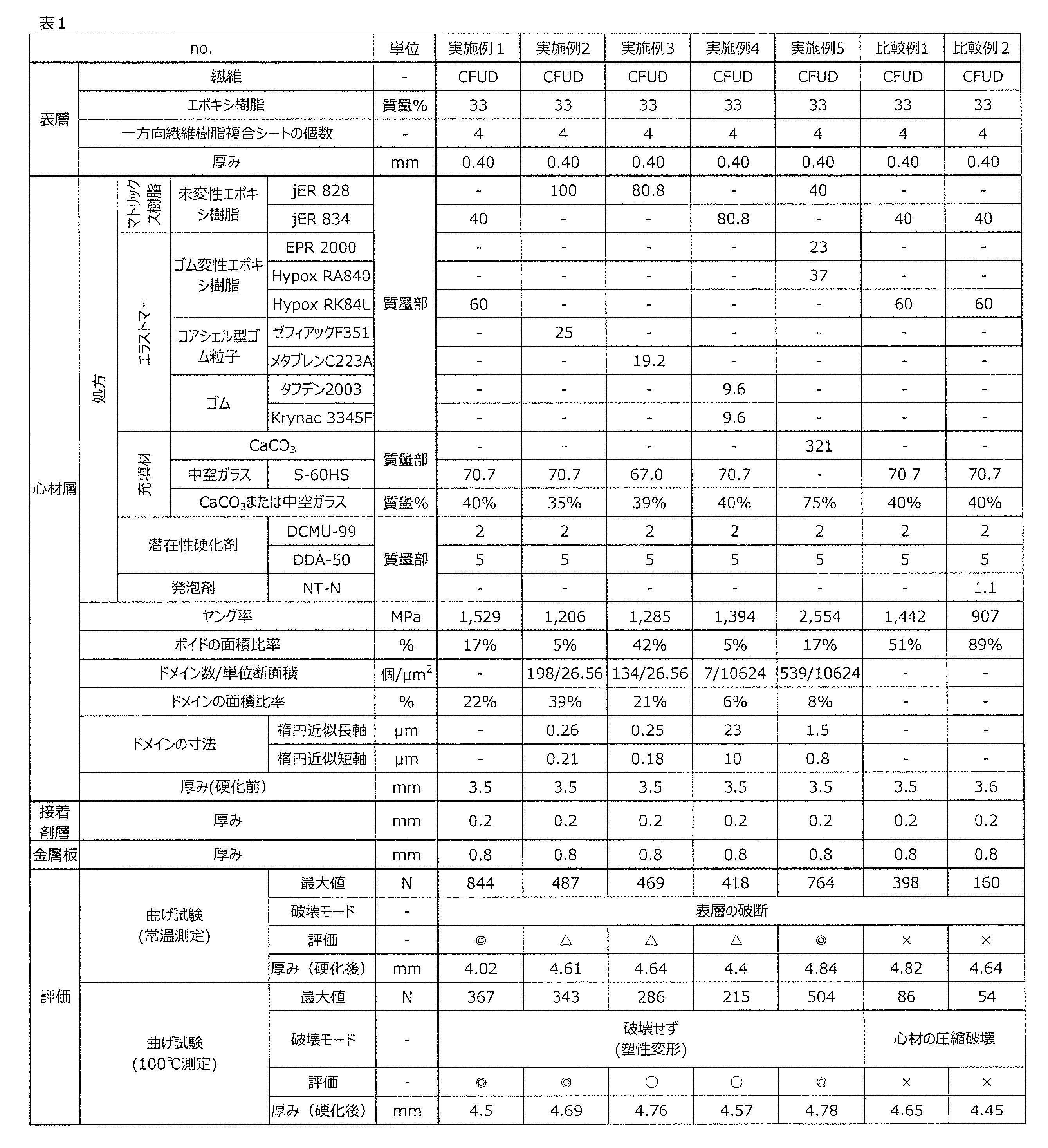
表1中の略号の詳細を下記する。
JER 828:未変性エポキシ樹脂、未硬化状態、エポキシ当量184g/eq~194g/eq、三菱ケミカル社製、
JER 834:未変性エポキシ樹脂、未硬化状態、エポキシ当量230g/eq~270g/eq、三菱ケミカル社製、
EPR2000:CTBN変性エポキシ樹脂、未硬化状態、エポキシ当量215g/eq、ADEKA社製、
HypoxRA840:CTBN変性エポキシ樹脂、未硬化状態、エポキシ当量350g/eq、CVC SpecialtyChemicals社製、
HypoxRK84L:CTBN変性エポキシ樹脂、未硬化状態、エポキシ当量1200~1800g/eq、CVC SpecialtyChemicals社製、
ゼフィアックF351:コアシェル型ゴム粒子(コア部 NBR、シェル部 アクリル系ポリマー)、アイカ工業社製、
メタブレンC223A:コアシェル型ゴム粒子(コア部 MBS、シェル部 アクリル系ポリマー)、三菱ケミカル社製、
タフデン2003:ゴム、ムーニー粘度(ML1+4、at100℃)33、ベール状、旭化成社製、
Krynac 3345F:ゴム、ムーニー粘度(ML1+4、at100℃)45±5、ベール状、Lanxess社製、
CaCO3:重質炭酸カルシウム、真密度2.7g/cm3、丸尾カルシウム社製、
S-60HS:中空ガラス、平均粒子径30μm、真密度0.6g/cm3、3M社製、
DCMU-99:尿素系化合物、3-(3,4-ジクロロフェニル)-1,1-ジメチルウレア、保土ヶ谷化学社製、
DDA-50:ジシアンジアミド、CVC Specialty Chemicals社製、
NT-N:永和化成工業社製。
なお、上記発明は、本発明の例示の実施形態として提供したが、これは単なる例示に過ぎず、限定的に解釈してはならない。当該技術分野の当業者によって明らかな本発明の変形例は、後記請求の範囲に含まれる。
本発明の補強シートおよび補強キットは、各種産業製品に使用される金属板の補強に適用することができ、例えば、輸送機械に用いられる金属板、家電製品に用いられる金属板などの補強に好適に用いられる。本発明の補強部材は、各種産業製品に適用することができ、例えば、輸送機械、家電製品などに好適に用いられる。
1 補強シート
2 心材層
3 表層
4 接着剤層
6 金属板
7 補強シート
8 補強キット
10 補強部材
11 補強部材
20 充填材
21 心材樹脂
22 マトリックス樹脂
23 ドメイン
24 ボイド
30 一方向繊維樹脂複合シート
2 心材層
3 表層
4 接着剤層
6 金属板
7 補強シート
8 補強キット
10 補強部材
11 補強部材
20 充填材
21 心材樹脂
22 マトリックス樹脂
23 ドメイン
24 ボイド
30 一方向繊維樹脂複合シート
Claims (14)
- 金属板に接着して前記金属板を補強するための補強シートであって、
樹脂を含有する心材層と、
前記心材層の厚み方向の一方側に配置される表層と、を備え、
前記表層は、複数の一方向繊維樹脂複合シートが積層されており、
前記心材層の固化物の断面におけるボイドの面積比率が、50%以下であることを特徴とする、補強シート。 - 前記心材層は、充填材をさらに含有し、
前記心材層における前記充填材の含有割合は、15質量%以上85質量%未満であることを特徴とする、請求項1に記載の補強シート。 - 前記樹脂は、マトリックス樹脂と、前記マトリックス樹脂中に分散する二相構造を形成するエラストマーとを含み、
前記心材層の固化物の断面における前記エラストマーからなるドメインの面積比率が、40%以下であることを特徴とする、請求項1または2に記載の補強シート。 - 前記樹脂は、マトリックス樹脂と、前記マトリックス樹脂中に分散する二相構造を形成するエラストマーとを含み、
前記心材層の固化物の断面における前記エラストマーからなるドメインの面積比率が、30%以下であることを特徴とする、請求項1または2に記載の補強シート。 - 前記心材層の固化物の断面積10624μm2あたりの前記ドメインの数が5以上であることを特徴とする、請求項3または4に記載の補強シート。
- 前記心材層の固化物の断面積26.56μm2あたりの前記ドメインの数が5以上であることを特徴とする、請求項3または4に記載の補強シート。
- 前記マトリックス樹脂は、未変性エポキシ樹脂を含み、
前記エラストマーは、ゴム変性エポキシ樹脂を含むことを特徴とする、請求項3~6のいずれか一項に記載の補強シート。 - 前記心材層の厚み方向の他方側に配置される接着剤層をさらに備えることを特徴とする、請求項1~7のいずれか一項に記載の補強シート。
- 前記複数の一方向繊維樹脂複合シートのそれぞれは、カーボン繊維またはガラス繊維と、熱硬化性樹脂とを含有することを特徴とする、請求項1~8のいずれか一項に記載の補強シート。
- 請求項1~9のいずれか一項に記載の補強シートと、
前記補強シートにより補強される金属板と、を備えることを特徴とする、補強部材。 - 金属板に接着して前記金属板を補強するための補強キットであって、
樹脂を含有する心材層と、
複数の一方向繊維樹脂複合シートが積層されている表層と、を備え、
前記心材層の固化物の断面におけるボイドの面積が、50%以下であることを特徴とする、補強キット。 - 金属板に接着して前記金属板を補強するための補強シートの製造方法であって、
樹脂を含有する心材層であって、前記心材層の固化物の断面におけるボイドの面積比率が50%以下である心材層を準備する工程と、
複数の一方向繊維樹脂複合シートが積層されている表層を準備する工程と、
前記表層を前記心材層の厚み方向の一方側に貼り付ける工程と、を含むことを特徴とする、補強シートの製造方法。 - 樹脂を含有する心材層であって、前記心材層の固化物の断面におけるボイドの面積比率が50%以下である心材層と、前記心材層の厚み方向の一方側に配置され、複数の一方向繊維樹脂複合シートが積層されている表層と、を備える補強シートを準備する工程と、
前記補強シートを金属板に貼り付けて、前記金属板を補強する工程と、を含むことを特徴とする、補強部材の製造方法。 - 樹脂を含有する心材層であって、前記心材層の固化物の断面におけるボイドの面積比率が50%以下である心材層を、金属板に貼り付ける工程と、
前記心材層における前記金属板と反対側の面に、複数の一方向繊維樹脂複合シートが積層されている表層を貼り付けて、前記金属板を補強する工程と、を含むことを特徴とする、補強部材の製造方法。
Priority Applications (4)
| Application Number | Priority Date | Filing Date | Title |
|---|---|---|---|
| US16/649,827 US11654655B2 (en) | 2017-09-29 | 2018-09-28 | Reinforcement sheet, reinforcement member, reinforcement kit, producing method of reinforcement sheet, and producing method of reinforcement member |
| JP2019545167A JP7287893B2 (ja) | 2017-09-29 | 2018-09-28 | 補強シート、補強部材、補強キット、補強シートの製造方法および補強部材の製造方法 |
| CN201880063425.3A CN111148630B (zh) | 2017-09-29 | 2018-09-28 | 增强片、增强构件、增强套件、增强片的制造方法及增强构件的制造方法 |
| EP18863464.6A EP3689600A4 (en) | 2017-09-29 | 2018-09-28 | REINFORCEMENT SHEET, REINFORCEMENT ELEMENT, REINFORCEMENT KIT, REINFORCEMENT SHEET PRODUCTION PROCESS AND REINFORCEMENT ELEMENT PRODUCTION PROCESS |
Applications Claiming Priority (2)
| Application Number | Priority Date | Filing Date | Title |
|---|---|---|---|
| JP2017-191287 | 2017-09-29 | ||
| JP2017191287 | 2017-09-29 |
Publications (1)
| Publication Number | Publication Date |
|---|---|
| WO2019066022A1 true WO2019066022A1 (ja) | 2019-04-04 |
Family
ID=65901986
Family Applications (2)
| Application Number | Title | Priority Date | Filing Date |
|---|---|---|---|
| PCT/JP2018/036423 WO2019066023A1 (ja) | 2017-09-29 | 2018-09-28 | 補強シート、補強部材、補強キット、補強シートの製造方法および補強部材の製造方法 |
| PCT/JP2018/036422 WO2019066022A1 (ja) | 2017-09-29 | 2018-09-28 | 補強シート、補強部材、補強キット、補強シートの製造方法および補強部材の製造方法 |
Family Applications Before (1)
| Application Number | Title | Priority Date | Filing Date |
|---|---|---|---|
| PCT/JP2018/036423 WO2019066023A1 (ja) | 2017-09-29 | 2018-09-28 | 補強シート、補強部材、補強キット、補強シートの製造方法および補強部材の製造方法 |
Country Status (5)
| Country | Link |
|---|---|
| US (2) | US11654656B2 (ja) |
| EP (2) | EP3689600A4 (ja) |
| JP (2) | JP7287894B2 (ja) |
| CN (2) | CN111148630B (ja) |
| WO (2) | WO2019066023A1 (ja) |
Citations (7)
| Publication number | Priority date | Publication date | Assignee | Title |
|---|---|---|---|---|
| JPH02169658A (ja) * | 1988-12-22 | 1990-06-29 | Yokohama Rubber Co Ltd:The | エポキシ樹脂組成物 |
| JPH07124981A (ja) * | 1993-11-01 | 1995-05-16 | Teijin Ltd | 複合成形品の製造法 |
| JP2005161852A (ja) * | 2003-11-13 | 2005-06-23 | Toray Ind Inc | 金属/繊維強化プラスチック複合材料及びその製造方法 |
| WO2008114669A1 (ja) * | 2007-03-12 | 2008-09-25 | Taisei Plas Co., Ltd. | アルミニウム合金複合体とその接合方法 |
| WO2008126812A1 (ja) * | 2007-04-06 | 2008-10-23 | Taisei Plas Co., Ltd. | 銅合金複合体とその製造方法 |
| JP2010058394A (ja) | 2008-09-04 | 2010-03-18 | Nitto Denko Corp | 鋼板補強シートおよびその製造方法 |
| JP2012082394A (ja) * | 2010-09-17 | 2012-04-26 | Toray Ind Inc | 炭素繊維織物プリプレグおよび炭素繊維強化複合材料 |
-
2018
- 2018-09-28 US US16/649,828 patent/US11654656B2/en active Active
- 2018-09-28 JP JP2019545168A patent/JP7287894B2/ja active Active
- 2018-09-28 EP EP18863464.6A patent/EP3689600A4/en active Pending
- 2018-09-28 CN CN201880063425.3A patent/CN111148630B/zh active Active
- 2018-09-28 EP EP18863465.3A patent/EP3689601A4/en active Pending
- 2018-09-28 JP JP2019545167A patent/JP7287893B2/ja active Active
- 2018-09-28 CN CN201880063337.3A patent/CN111163937A/zh active Pending
- 2018-09-28 WO PCT/JP2018/036423 patent/WO2019066023A1/ja unknown
- 2018-09-28 US US16/649,827 patent/US11654655B2/en active Active
- 2018-09-28 WO PCT/JP2018/036422 patent/WO2019066022A1/ja unknown
Patent Citations (7)
| Publication number | Priority date | Publication date | Assignee | Title |
|---|---|---|---|---|
| JPH02169658A (ja) * | 1988-12-22 | 1990-06-29 | Yokohama Rubber Co Ltd:The | エポキシ樹脂組成物 |
| JPH07124981A (ja) * | 1993-11-01 | 1995-05-16 | Teijin Ltd | 複合成形品の製造法 |
| JP2005161852A (ja) * | 2003-11-13 | 2005-06-23 | Toray Ind Inc | 金属/繊維強化プラスチック複合材料及びその製造方法 |
| WO2008114669A1 (ja) * | 2007-03-12 | 2008-09-25 | Taisei Plas Co., Ltd. | アルミニウム合金複合体とその接合方法 |
| WO2008126812A1 (ja) * | 2007-04-06 | 2008-10-23 | Taisei Plas Co., Ltd. | 銅合金複合体とその製造方法 |
| JP2010058394A (ja) | 2008-09-04 | 2010-03-18 | Nitto Denko Corp | 鋼板補強シートおよびその製造方法 |
| JP2012082394A (ja) * | 2010-09-17 | 2012-04-26 | Toray Ind Inc | 炭素繊維織物プリプレグおよび炭素繊維強化複合材料 |
Non-Patent Citations (1)
| Title |
|---|
| See also references of EP3689600A4 |
Also Published As
| Publication number | Publication date |
|---|---|
| US11654656B2 (en) | 2023-05-23 |
| JP7287894B2 (ja) | 2023-06-06 |
| US20200282704A1 (en) | 2020-09-10 |
| US20200282703A1 (en) | 2020-09-10 |
| EP3689601A1 (en) | 2020-08-05 |
| EP3689601A4 (en) | 2021-06-23 |
| CN111163937A (zh) | 2020-05-15 |
| CN111148630A (zh) | 2020-05-12 |
| EP3689600A1 (en) | 2020-08-05 |
| JPWO2019066022A1 (ja) | 2020-10-22 |
| CN111148630B (zh) | 2022-05-06 |
| JP7287893B2 (ja) | 2023-06-06 |
| US11654655B2 (en) | 2023-05-23 |
| WO2019066023A1 (ja) | 2019-04-04 |
| EP3689600A4 (en) | 2021-07-28 |
| JPWO2019066023A1 (ja) | 2020-11-05 |
Similar Documents
| Publication | Publication Date | Title |
|---|---|---|
| JP5969217B2 (ja) | 両面接着テープ | |
| EP2542403B1 (en) | Structural composite laminate | |
| WO2012073775A1 (ja) | 金属複合体の製造方法および電子機器筐体 | |
| TW201831321A (zh) | 金屬-纖維強化樹脂材料複合體、其製造方法以及接著片 | |
| JP5415698B2 (ja) | 制振補強シート、および薄板の制振補強方法 | |
| TW200815505A (en) | Molded object and method for producing the same | |
| KR20140030181A (ko) | 충격 개질된 접착제 | |
| JP5604115B2 (ja) | 外板用補強材および外板の補強方法 | |
| CN111278641B (zh) | 层叠物及加强片 | |
| JP7287893B2 (ja) | 補強シート、補強部材、補強キット、補強シートの製造方法および補強部材の製造方法 | |
| WO2019102810A1 (ja) | 補強構造体および補強構造体の製造方法 | |
| EP4372062A1 (en) | Method for manufacturing joined body | |
| JP6371443B2 (ja) | 両面接着テープ | |
| JP4821159B2 (ja) | エポキシ樹脂組成物の製造方法 | |
| JP2018030246A (ja) | 補強構造、補強構造の製造方法、および、補強キット | |
| CN117580703A (zh) | 接合体的制造方法 | |
| JP2019065243A (ja) | フレキシブルプリント配線板補強用硬化性接着シート、補強部付フレキシブルプリント配線板、その製造方法及び電子機器 |
Legal Events
| Date | Code | Title | Description |
|---|---|---|---|
| 121 | Ep: the epo has been informed by wipo that ep was designated in this application |
Ref document number: 18863464 Country of ref document: EP Kind code of ref document: A1 |
|
| ENP | Entry into the national phase |
Ref document number: 2019545167 Country of ref document: JP Kind code of ref document: A |
|
| NENP | Non-entry into the national phase |
Ref country code: DE |
|
| ENP | Entry into the national phase |
Ref document number: 2018863464 Country of ref document: EP Effective date: 20200429 |