WO2019065907A1 - 作業車両、表示装置、および障害判定方法 - Google Patents
作業車両、表示装置、および障害判定方法 Download PDFInfo
- Publication number
- WO2019065907A1 WO2019065907A1 PCT/JP2018/036110 JP2018036110W WO2019065907A1 WO 2019065907 A1 WO2019065907 A1 WO 2019065907A1 JP 2018036110 W JP2018036110 W JP 2018036110W WO 2019065907 A1 WO2019065907 A1 WO 2019065907A1
- Authority
- WO
- WIPO (PCT)
- Prior art keywords
- image
- work vehicle
- change
- imaging device
- display device
- Prior art date
- Legal status (The legal status is an assumption and is not a legal conclusion. Google has not performed a legal analysis and makes no representation as to the accuracy of the status listed.)
- Ceased
Links
Images


Classifications
-
- E—FIXED CONSTRUCTIONS
- E02—HYDRAULIC ENGINEERING; FOUNDATIONS; SOIL SHIFTING
- E02F—DREDGING; SOIL-SHIFTING
- E02F9/00—Component parts of dredgers or soil-shifting machines, not restricted to one of the kinds covered by groups E02F3/00 - E02F7/00
- E02F9/26—Indicating devices
- E02F9/261—Surveying the work-site to be treated
- E02F9/262—Surveying the work-site to be treated with follow-up actions to control the work tool, e.g. controller
-
- B—PERFORMING OPERATIONS; TRANSPORTING
- B60—VEHICLES IN GENERAL
- B60Q—ARRANGEMENT OF SIGNALLING OR LIGHTING DEVICES, THE MOUNTING OR SUPPORTING THEREOF OR CIRCUITS THEREFOR, FOR VEHICLES IN GENERAL
- B60Q1/00—Arrangement of optical signalling or lighting devices, the mounting or supporting thereof or circuits therefor
- B60Q1/26—Arrangement of optical signalling or lighting devices, the mounting or supporting thereof or circuits therefor the devices being primarily intended to indicate the vehicle, or parts thereof, or to give signals, to other traffic
- B60Q1/50—Arrangement of optical signalling or lighting devices, the mounting or supporting thereof or circuits therefor the devices being primarily intended to indicate the vehicle, or parts thereof, or to give signals, to other traffic for indicating other intentions or conditions, e.g. request for waiting or overtaking
- B60Q1/543—Arrangement of optical signalling or lighting devices, the mounting or supporting thereof or circuits therefor the devices being primarily intended to indicate the vehicle, or parts thereof, or to give signals, to other traffic for indicating other intentions or conditions, e.g. request for waiting or overtaking for indicating other states or conditions of the vehicle
-
- B—PERFORMING OPERATIONS; TRANSPORTING
- B60—VEHICLES IN GENERAL
- B60R—VEHICLES, VEHICLE FITTINGS, OR VEHICLE PARTS, NOT OTHERWISE PROVIDED FOR
- B60R1/00—Optical viewing arrangements; Real-time viewing arrangements for drivers or passengers using optical image capturing systems, e.g. cameras or video systems specially adapted for use in or on vehicles
- B60R1/20—Real-time viewing arrangements for drivers or passengers using optical image capturing systems, e.g. cameras or video systems specially adapted for use in or on vehicles
- B60R1/22—Real-time viewing arrangements for drivers or passengers using optical image capturing systems, e.g. cameras or video systems specially adapted for use in or on vehicles for viewing an area outside the vehicle, e.g. the exterior of the vehicle
- B60R1/23—Real-time viewing arrangements for drivers or passengers using optical image capturing systems, e.g. cameras or video systems specially adapted for use in or on vehicles for viewing an area outside the vehicle, e.g. the exterior of the vehicle with a predetermined field of view
- B60R1/24—Real-time viewing arrangements for drivers or passengers using optical image capturing systems, e.g. cameras or video systems specially adapted for use in or on vehicles for viewing an area outside the vehicle, e.g. the exterior of the vehicle with a predetermined field of view in front of the vehicle
-
- E—FIXED CONSTRUCTIONS
- E02—HYDRAULIC ENGINEERING; FOUNDATIONS; SOIL SHIFTING
- E02F—DREDGING; SOIL-SHIFTING
- E02F3/00—Dredgers; Soil-shifting machines
- E02F3/04—Dredgers; Soil-shifting machines mechanically-driven
- E02F3/28—Dredgers; Soil-shifting machines mechanically-driven with digging tools mounted on a dipper- or bucket-arm, i.e. there is either one arm or a pair of arms, e.g. dippers, buckets
- E02F3/36—Component parts
- E02F3/42—Drives for dippers, buckets, dipper-arms or bucket-arms
- E02F3/43—Control of dipper or bucket position; Control of sequence of drive operations
- E02F3/435—Control of dipper or bucket position; Control of sequence of drive operations for dipper-arms, backhoes or the like
-
- E—FIXED CONSTRUCTIONS
- E02—HYDRAULIC ENGINEERING; FOUNDATIONS; SOIL SHIFTING
- E02F—DREDGING; SOIL-SHIFTING
- E02F9/00—Component parts of dredgers or soil-shifting machines, not restricted to one of the kinds covered by groups E02F3/00 - E02F7/00
- E02F9/20—Drives; Control devices
- E02F9/2025—Particular purposes of control systems not otherwise provided for
- E02F9/205—Remotely operated machines, e.g. unmanned vehicles
-
- E—FIXED CONSTRUCTIONS
- E02—HYDRAULIC ENGINEERING; FOUNDATIONS; SOIL SHIFTING
- E02F—DREDGING; SOIL-SHIFTING
- E02F9/00—Component parts of dredgers or soil-shifting machines, not restricted to one of the kinds covered by groups E02F3/00 - E02F7/00
- E02F9/26—Indicating devices
-
- E—FIXED CONSTRUCTIONS
- E02—HYDRAULIC ENGINEERING; FOUNDATIONS; SOIL SHIFTING
- E02F—DREDGING; SOIL-SHIFTING
- E02F9/00—Component parts of dredgers or soil-shifting machines, not restricted to one of the kinds covered by groups E02F3/00 - E02F7/00
- E02F9/26—Indicating devices
- E02F9/264—Sensors and their calibration for indicating the position of the work tool
- E02F9/265—Sensors and their calibration for indicating the position of the work tool with follow-up actions (e.g. control signals sent to actuate the work tool)
-
- H—ELECTRICITY
- H04—ELECTRIC COMMUNICATION TECHNIQUE
- H04N—PICTORIAL COMMUNICATION, e.g. TELEVISION
- H04N17/00—Diagnosis, testing or measuring for television systems or their details
- H04N17/004—Diagnosis, testing or measuring for television systems or their details for digital television systems
-
- H—ELECTRICITY
- H04—ELECTRIC COMMUNICATION TECHNIQUE
- H04N—PICTORIAL COMMUNICATION, e.g. TELEVISION
- H04N7/00—Television systems
- H04N7/18—Closed-circuit television [CCTV] systems, i.e. systems in which the video signal is not broadcast
- H04N7/183—Closed-circuit television [CCTV] systems, i.e. systems in which the video signal is not broadcast for receiving images from a single remote source
-
- H—ELECTRICITY
- H04—ELECTRIC COMMUNICATION TECHNIQUE
- H04Q—SELECTING
- H04Q9/00—Arrangements in telecontrol or telemetry systems for selectively calling a substation from a main station, in which substation desired apparatus is selected for applying a control signal thereto or for obtaining measured values therefrom
-
- B—PERFORMING OPERATIONS; TRANSPORTING
- B60—VEHICLES IN GENERAL
- B60Q—ARRANGEMENT OF SIGNALLING OR LIGHTING DEVICES, THE MOUNTING OR SUPPORTING THEREOF OR CIRCUITS THEREFOR, FOR VEHICLES IN GENERAL
- B60Q2800/00—Features related to particular types of vehicles not otherwise provided for
- B60Q2800/20—Utility vehicles, e.g. for agriculture, construction work
-
- E—FIXED CONSTRUCTIONS
- E02—HYDRAULIC ENGINEERING; FOUNDATIONS; SOIL SHIFTING
- E02F—DREDGING; SOIL-SHIFTING
- E02F3/00—Dredgers; Soil-shifting machines
- E02F3/04—Dredgers; Soil-shifting machines mechanically-driven
- E02F3/28—Dredgers; Soil-shifting machines mechanically-driven with digging tools mounted on a dipper- or bucket-arm, i.e. there is either one arm or a pair of arms, e.g. dippers, buckets
- E02F3/30—Dredgers; Soil-shifting machines mechanically-driven with digging tools mounted on a dipper- or bucket-arm, i.e. there is either one arm or a pair of arms, e.g. dippers, buckets with a dipper-arm pivoted on a cantilever beam, i.e. boom
- E02F3/308—Dredgers; Soil-shifting machines mechanically-driven with digging tools mounted on a dipper- or bucket-arm, i.e. there is either one arm or a pair of arms, e.g. dippers, buckets with a dipper-arm pivoted on a cantilever beam, i.e. boom working outwardly
Definitions
- the present invention relates to a work vehicle that captures an image and transmits the image remotely, a display device, and a fault determination method.
- a work vehicle that captures an image and transmits the image remotely, a display device, and a fault determination method.
- Patent Document 1 discloses a technique for facilitating appropriate control by an operator in a control room by photographing a rotating lamp with a television camera.
- An aspect of the present invention is to provide a work vehicle, a display device, and a fault determination method capable of making a remote operator recognize the presence or absence of a fault in an image system.
- a work vehicle includes a work machine, a change which is an object that causes a known change in appearance every certain time, and at least a part of the work machine and the change
- the imaging device comprises an imaging device for imaging a range, and a transmission device for transmitting an image captured by the imaging device.
- the work vehicle can cause the remote operator to recognize the presence or absence of the image system failure.
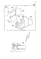
- FIG. 1 is an external view of a work vehicle according to a first embodiment. It is an example of the image which the imaging device of the working vehicle which concerns on 1st Embodiment images. It is an example of the image displayed on the display apparatus of the remote control room which concerns on 1st Embodiment. It is a flowchart which shows the failure determination method of the image system which concerns on 1st Embodiment. It is a schematic block diagram which shows the structure of the failure determination apparatus which concerns on other embodiment.
- FIG. 1 is a schematic view showing the configuration of the remote control system according to the first embodiment.
- the remote control system 1 includes a work vehicle 100 operated by remote control and a remote operation room 500.
- the work vehicle 100 is provided at a work site (for example, a mine, a quarry).
- Remote operator's cab 500 is provided at a point away from work vehicle 100 (for example, in the city, in a work site).
- the work vehicle 100 and the remote driver's cab 500 are connected via a network such as the Internet.
- the remote control system 1 is a system for operating the work vehicle 100 using the remote driver's cab 500.
- Work vehicle 100 operates in accordance with an operation signal received from remote operator's cab 500.
- Remote operator's cab 500 receives an operation of work vehicle 100 by the operation of the operator, and transmits an operation signal to work vehicle 100.
- FIG. 2 is an external view of the work vehicle according to the first embodiment.
- the work vehicle 100 according to the first embodiment is a hydraulic shovel.
- the work vehicle 100 according to another embodiment may be a work vehicle such as a wheel loader or a bulldozer other than a hydraulic shovel.
- the work vehicle 100 includes a work machine 110 operated by hydraulic pressure, a swing body 120 supporting the work machine 110, and a traveling body 130 supporting the swing body 120.
- the work implement 110 includes a boom 111, an arm 112, and a bucket 113.
- the proximal end of the boom 111 is attached to the rotating body 120 via a pin.
- the arm 112 couples the boom 111 and the bucket 113.
- the proximal end of the arm 112 is attached to the distal end of the boom 111 via a pin.
- the bucket 113 includes a blade for excavating earth and sand and a container for transporting the excavated earth and sand.
- the proximal end of the bucket 113 is attached to the distal end of the arm 112 via a pin.
- the revolving structure 120 is provided with a cab 121.
- a mode lamp 126 is provided in front of the cab 121.
- the mode lamp 126 includes a plurality of lamps (for example, LEDs (Light Emitting Diodes)), and at least one of the plurality of lamps blinks according to the driving state of the work vehicle 100.
- the blinking pattern of each lamp is predetermined. That is, the lamp is an example of a variation in which a known change occurs in appearance every predetermined time.
- the mode lamp 126 includes, for example, a first lamp that issues green, a second lamp that issues yellow, and a third lamp that issues red, from the left to the outside from the driver's seat, for example.
- the first lamp blinks.
- the second lamp blinks.
- the third lamp blinks.
- all the lamps blink.
- the first lamp and the second lamp blink.
- the mode lamps 126 may be mounted not only in front of the driver's seat 510 but also at the four corners of the revolving unit 120. Also, the lamps may be arranged vertically. Thereby, the worker who is outside work vehicle 100 can recognize the operation mode of work vehicle 100.
- the lamp included in the mode lamp 126 may be a rotary lamp that reflects light emitted from the light source by a reflecting mirror that rotates around the light source.
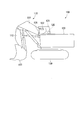
- FIG. 3 is an example of an image captured by the imaging device of the work vehicle according to the first embodiment.
- An imaging device 122 is provided in the upper part of the cab 121.
- the imaging device 122 is installed forward and upward in the cab 121.
- the imaging device 122 captures an image (for example, a moving image) in front of the cab 121 through the windshield on the front surface of the cab 121.
- Examples of the imaging device 122 include, for example, an imaging device using a charge coupled device (CCD) sensor and a complementary metal oxide semiconductor (CMOS) sensor.
- CCD charge coupled device
- CMOS complementary metal oxide semiconductor
- the imaging device 122 images a range in which the work object in front of the work implement 110, the mode lamp 126, and the cab 121 is captured. That is, as shown in FIG. 3, the work object range in front of the work implement 110, the mode lamp 126, and the driver's cab 121 is captured in the image P1 captured by the imaging device 122.
- the work vehicle 100 includes a control device 125.
- the control device 125 includes an image coding device (not shown), and codes an image captured by the imaging device 122.
- the controller 125 transmits the encoded image to the remote control room 500.
- the image coding apparatus may be provided separately from the control device 125.
- the controller 125 receives an operation signal from the remote driver's cab 500.
- the control device 125 drives the work implement 110, the swing body 120, or the traveling body 130 in accordance with the received operation signal.
- the remote driver's cab 500 includes a driver's seat 510, a display 520, an operating device 530, and a controller 540.
- the display device 520 is disposed in front of the driver's seat 510.
- the display device 520 is located in front of the operator when the operator sits in the driver's seat 510.
- the display device 520 is configured by an arrayed display 521, a display 522, a display 523, a display 524, and a display 525 as shown in FIG. In other embodiments, the number of displays constituting the display device 520 is not limited to this.
- the display device 520 may be configured by one display.
- the display device 520 may project an image on a curved surface or a spherical surface by a projector or the like.
- Operation device 530 is arranged in the vicinity of driver's seat 510.
- the operating device 530 is located within the operable range of the operator when the operator sits on the driver's seat 510.
- the operating device 530 includes, for example, an electric lever and an electric pedal.
- FIG. 4 is an example of an image displayed on the display device of the remote operation room according to the first embodiment.
- the control device 540 causes the image P11 to be displayed on the display 521, the image P12 to be displayed on the display 522, and the display 523 from the image P1 captured by the imaging device 122.
- An image P13 for image, an image P14 for displaying on the display 524, and an image P15 for displaying on the display 525 are cut out.
- the control device 540 performs clipping so that a portion in which the mode lamp 126 and a part of the work implement 110 appear from at least one of the image P11 to the image P15.
- the control device 540 performs clipping so that the portion in which the mode lamp 126 is captured remains in the image P11.
- Control device 540 causes display 521 to display image P11. Control device 540 causes display 522 to display image P12. Control device 540 causes display 523 to display image P13. Control device 540 causes display 524 to display image P14. Control device 540 causes display 525 to display image P15.
- control device 540 superimposes image P2 which is an image captured by a back camera (not shown) or an image representing vehicle information (such as an inclination state of the vehicle body) on any one of images P11 to P15 to display device 520. Display on part of At this time, the control device 540 superimposes an image captured by a back camera (not shown) and an image representing vehicle information on a portion of the image captured by the imaging device 122 where the mode lamp 126 is not captured. That is, on the display device 520, an image of the mode lamp 126 is always displayed. In the example illustrated in FIG. 4, the control device 540 causes the display 525 to display the image P2 so as to be superimposed on the image P15.
- Control device 540 transmits an operation signal representing an operation of operation device 530 to work vehicle 100.
- FIG. 5 is a flowchart showing an image-based failure determination method according to the first embodiment.
- the image system refers to a transmission path of an image including the imaging device 122, the control device 125, the control device 540, and the display device 520.
- control device 540 of remote driver's cab 500 acquires images P11 to P15 with mode lamp 126 taken from control device 125 of work vehicle 100 (step S1), and displays images P11 to P15 on display device 520.
- the operator visually recognizes a portion of the image displayed on the display device 520 where the mode lamp 126 is displayed, and determines whether the displayed image changes at regular time intervals (step S2).
- step S3 If the displayed image changes at regular time intervals (step S2: YES), the operator determines that no failure occurs in the image system (step S3). On the other hand, if the displayed image does not change at regular time intervals (step S2: YES), the operator determines that a failure of the image system has occurred (step S4).
- the display device 520 always displays the image of the mode lamp 126.
- the image captured by the imaging device 122 reaches the display device 520 via the image system.
- transmission of the image is stopped, and the image displayed on the display device 520 may not be updated.
- the imaging device 122 captures a moving image
- the same frame image continues to be displayed on the display device 520 while the updating is not performed.
- the display device 520 continues to display the same still image captured before a failure occurs.
- the image displayed on the display device 520 appears to the operator to be stopped.
- the operator visually recognizes a portion where the mode lamp 126 is displayed among the images displayed on the display device 520, and the working machine 110 stops because the image appears to be stopped due to the failure of the image system.
- it can be determined whether the image appears to stop due to the small amount of movement.
- the appearance of the mode lamp 126 changes at least during transmission and reception of the image regardless of the operation of the operation device 530, so that the operator can determine the presence or absence of a failure even if the work implement 110 is not moving. That is, the work vehicle 100 according to the present embodiment can cause the remote operator to recognize the presence or absence of a failure in the image system.
- the operator can stop the operation of the work vehicle 100 and wait for the recovery of the failure.
- Comparative Example As a comparative example, consider a work vehicle 100 in which the imaging device 122 does not capture the mode lamp 126 and the control device 125 combines an animation image that changes at a constant cycle with an image captured by the imaging device 122.
- the animation image displayed on the display device 520 changes at a constant cycle.
- the animation image is stopped, so that the operator can recognize that the failure has occurred. .
- the control device 125 synthesizes the animation image with the same image, so that the failure occurs in the image system. Although generated, the animation image displayed on the display device 520 changes in a constant cycle. Therefore, the operator can not recognize that a failure has occurred.
- the change of the mode lamp 126 is stopped regardless of where in the image system a failure occurs, so that the operator can reliably confirm the presence or absence of the image system failure. Can be recognized.
- the work vehicle 100 includes the mode lamp 126 as a change that causes a known change in appearance every certain time, but is not limited thereto.
- the work vehicle 100 may include other lamps, blinking lights, a clock (particularly, a second hand) as a change, a monitor that displays an image having a known change in a predetermined time, and the like.
- these variations are additionally provided to the work vehicle 100, it is preferable to provide them at positions such as pillars that do not block the view.
- the variation may be any one that causes a known change in appearance at least during transmission and reception of an image captured by the imaging device 122. That is, the variation may be one whose appearance does not change while the image is not transmitted / received.
- the mode lamp 126 which concerns on embodiment mentioned above is installed ahead of the cab 121, it is not restricted to this.
- the change object may be installed inside the driver's cab.
- the work vehicle 100 may include a mirror, and the image of the change object reflected by the mirror may be included in the imaging range of the imaging device 122.
- the image of the change object reflected by the vehicle body may be included in the imaging range of the imaging device 122.
- control apparatus 540 which concerns on embodiment mentioned above produces
- the images P11 to P15 are generated by performing clipping so that the portion where the mode lamp 126 does not appear remains, and further, the region where the mode lamp 126 appears is cut out from the image P1.
- To P15 may be superimposed and displayed.
- the presence or absence of a fault is determined by the operator visually recognizing the mode lamp 126 shown on the display device 520, but the present invention is not limited to this.
- the computer may determine the presence or absence of a failure by monitoring the amount of change in brightness of the portion of the image P1 where the mode lamp 126 is captured.
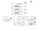
- FIG. 6 is a schematic block diagram showing the configuration of a failure determination apparatus according to another embodiment.
- the remote operation room 500 may be provided with the failure determination device 900 shown in FIG. 6, and the failure determination device 900 may determine the presence or absence of an image failure.
- the failure determination device 900 is a computer including a processor 910, a main memory 920, a storage 930, an interface 940, and an imaging device 950.
- the storage 930 stores the program p.
- the processor 910 reads the program p from the storage 930, develops it in the main memory 920, and executes processing in accordance with the program p.
- the failure determination device 900 is connected to the imaging device 950 via the interface 940.
- the imaging device 950 captures at least a portion of the image displayed on the display device 520 where the mode lamp 126 appears.
- Examples of the storage 930 include a hard disk drive (HDD), a solid state drive (SSD), a magnetic disk, an optical magnetic disk, a compact disc read only memory (CD-ROM), and a digital versatile disc read only memory (DVD-ROM). , Semiconductor memory and the like.
- the storage 930 may be internal media directly connected to the common communication line of the failure determination apparatus 900, or may be external media connected to the failure determination apparatus 900 via the interface 940.
- the storage 930 is a non-temporary, tangible storage medium.
- the processor 910 includes an image acquisition unit 911, a lightness identification unit 912, and a failure determination unit 913 by executing the program p.
- the image acquisition unit 911 acquires an image from the imaging device 950.
- the lightness specifying unit 912 specifies the lightness of the portion where the mode lamp 126 appears in the acquired image.
- the fault determining unit 913 determines whether or not there is a fault in the image system by determining whether the lightness of the portion where the mode lamp 126 appears is changing at regular time intervals.
- the fault determining apparatus 900 determines a fault of the image system by the same process as the flowchart shown in FIG. That is, the image acquisition unit 911 acquires an image in which the mode lamp 126 is captured from the imaging device 950 (step S1).
- the lightness specifying unit 912 specifies the lightness of the portion of the acquired image where the mode lamp 126 is displayed.
- the fault determining unit 913 determines whether the lightness changes at fixed time intervals (step S2). When the lightness is changing for each fixed time (step S2: YES), the failure determining unit 913 determines that no failure occurs in the image system (step S3). On the other hand, when the lightness does not change for every fixed time (step S2: YES), the failure determining unit 913 determines that a failure of the image system has occurred (step S4).
- the failure determination apparatus 900 can determine the presence or absence of a failure in the image system. In other embodiments, the above determination may be performed based on the image received by the control device 540. On the other hand, in the case where the control device 540 makes a determination, if a failure occurs between the control device 540 and the display device 520, this can not be detected. Therefore, like the failure determination device 900, the display device 520. It is preferable to determine the fault based on the image displayed on the screen.
- the work vehicle can cause a remote operator to recognize the presence or absence of an image system failure.
Landscapes
- Engineering & Computer Science (AREA)
- Mechanical Engineering (AREA)
- Multimedia (AREA)
- Civil Engineering (AREA)
- General Engineering & Computer Science (AREA)
- Structural Engineering (AREA)
- Mining & Mineral Resources (AREA)
- Signal Processing (AREA)
- Biomedical Technology (AREA)
- General Health & Medical Sciences (AREA)
- Health & Medical Sciences (AREA)
- Computer Networks & Wireless Communication (AREA)
- Component Parts Of Construction Machinery (AREA)
- Closed-Circuit Television Systems (AREA)
- Selective Calling Equipment (AREA)
Abstract
Description
本願は、2017年9月29日に日本に出願された特願2017-191293号について優先権を主張し、その内容をここに援用する。
なお、特許文献1には、回転灯をテレビカメラで撮影することで、コントロールルームのオペレータによる適切な制御を容易にする技術が開示されている。
本発明の態様は、遠隔のオペレータに画像系の障害の有無を認識させることができる作業車両、表示装置、および障害判定方法を提供することを目的とする。
《システム》
図1は、第1の実施形態に係る遠隔操作システムの構成を示す概略図である。
遠隔操作システム1は、遠隔操作により動作する作業車両100と、遠隔運転室500とを備える。作業車両100は、作業現場(例えば、鉱山、採石場)に設けられる。遠隔運転室500は、作業車両100から離れた地点(例えば、市街、作業現場内)に設けられる。作業車両100と遠隔運転室500とは、インターネットなどのネットワークを介して接続される。
遠隔操作システム1は、遠隔運転室500を用いて作業車両100を操作するためのシステムである。
遠隔運転室500は、オペレータの操作により、作業車両100の操作を受け付け、操作信号を作業車両100に送信する。
図2は、第1の実施形態に係る作業車両の外観図である。
第1の実施形態に係る作業車両100は、油圧ショベルである。なお、他の実施形態に係る作業車両100は、油圧ショベル以外の例えばホイールローダ、ブルドーザ等の作業車両であってもよい。
作業車両100は、油圧により作動する作業機110と、作業機110を支持する旋回体120と、旋回体120を支持する走行体130とを備える。
アーム112は、ブーム111とバケット113とを連結する。アーム112の基端部は、ブーム111の先端部にピンを介して取り付けられる。
バケット113は、土砂などを掘削するための刃と掘削した土砂を搬送するための容器とを備える。バケット113の基端部は、アーム112の先端部にピンを介して取り付けられる。
運転室121の前方には、モードランプ126が設けられる。モードランプ126は、複数のランプ(例えば、LED(Light Emitting Diode)など)を備え、作業車両100の運転状態に応じて複数のランプのうち少なくとも1つが点滅する。各ランプの点滅のパターンはあらかじめ定められている。すなわち、ランプは、一定時間ごとに外観に既知の変化が生じる変化物の一例である。
モードランプ126は、例えば、運転席から外側に向かって左から順に、緑色に発行する第1ランプ、黄色に発行する第2ランプ、赤色に発行する第3ランプを備え、以下のような挙動をしてもよい。作業車両100が有人運転状態である場合に、第1ランプが点滅する。作業車両100が遠隔操作状態である場合に、第2ランプが点滅する。作業車両100がエラー状態である場合に、第3ランプが点滅する。作業車両100が有人運転と遠隔操作との切替中である場合に、すべてのランプが点滅する。作業車両100がメンテナンス中である場合に、第1ランプと第2ランプとが点滅する。モードランプ126は、運転席510の前方のみならず、旋回体120の四隅に取り付けられていてもよい。また各ランプは、縦に並べて配置されてもよい。
これにより、作業車両100の外にいる作業者は、作業車両100の運転モードを認識することができる。作業車両100が駆動している間、操作信号の有無に関わらず、常にモードランプ126の少なくとも1つのランプが点滅する。なお、モードランプ126が備えるランプは、光源の周りを回転する反射鏡によって光源が放つ光を反射させる回転灯であってもよい。
運転室121の上部には、撮像装置122が設けられる。撮像装置122は、運転室121内の前方かつ上方に設置される。撮像装置122は、運転室121前面のフロントガラスを通して、運転室121の前方の画像(例えば、動画像)を撮像する。撮像装置122の例としては、例えばCCD(Charge Coupled Device)センサ、およびCMOS(Complementary Metal Oxide Semiconductor)センサを用いた撮像装置が挙げられる。撮像装置122は、作業機110、モードランプ126および運転室121の前方の作業対象が写る範囲を撮像する。つまり、撮像装置122が撮像する画像P1には、図3に示すように、作業機110、モードランプ126および運転室121の前方の作業対象範囲が写る。
制御装置125は、図示しない画像符号化装置を備え、撮像装置122が撮像した画像を符号化する。制御装置125は、符号化された画像を、遠隔運転室500に送信する。なお、画像符号化装置は、制御装置125と別個に設けられたものであってもよい。
制御装置125は、遠隔運転室500から操作信号を受信する。制御装置125は、受信した操作信号に従って、作業機110、旋回体120、または走行体130を駆動させる。
遠隔運転室500は、運転席510、表示装置520、操作装置530、制御装置540を備える。
表示装置520は、運転席510の前方に配置される。表示装置520は、オペレータが運転席510に座ったときにオペレータの眼前に位置する。表示装置520は、図1に示すように、並べられたディスプレイ521、ディスプレイ522、ディスプレイ523、ディスプレイ524、ディスプレイ525によって構成される。なお、他の実施形態においては、表示装置520を構成するディスプレイの数はこれに限られない。例えば、表示装置520は1つのディスプレイによって構成されてもよい。また、表示装置520は、プロジェクタ等によって曲面や球面に画像を投影するものであってもよい。
制御装置540は、作業車両100から受信した画像のうち、撮像装置122が撮像した画像P1から、ディスプレイ521に表示させるための画像P11、ディスプレイ522に表示させるための画像P12、ディスプレイ523に表示させるための画像P13、ディスプレイ524に表示させるための画像P14、ディスプレイ525に表示させるための画像P15をそれぞれ切り出す。このとき、制御装置540は、画像P11から画像P15の少なくとも1つにモードランプ126および作業機110の一部が写る部分が残るように切り出しを行う。図4に示す例では、制御装置540は、画像P11にモードランプ126が写る部分が残るように切り出しを行う。
図5は、第1の実施形態に係る画像系の障害判定方法を示すフローチャートである。本実施形態において画像系とは、撮像装置122、制御装置125、制御装置540、および表示装置520を含む画像の伝達経路をいう。
上述の構成により、遠隔運転室500の制御装置540は、作業車両100の制御装置125からモードランプ126が写る画像P11からP15を取得し(ステップS1)、画像P11からP15を表示装置520に表示させる。オペレータは、表示装置520に表示された画像のうち、モードランプ126が表示される部分を視認し、表示された画像が一定時間ごとに変化しているか否かを判定する(ステップS2)。表示された画像が一定時間ごとに変化している場合(ステップS2:YES)、オペレータは、画像系の障害が発生していないと判定する(ステップS3)。他方、表示された画像が一定時間ごとに変化していない場合(ステップS2:YES)、オペレータは、画像系の障害が発生していると判定する(ステップS4)。
上記構成により、表示装置520には、常にモードランプ126の画像が表示される。撮像装置122が撮像した画像は、画像系を経由して、表示装置520に到達する。画像系で障害が発生すると、画像の伝送が停止するため、表示装置520に表示される画像が更新されなくなる可能性がある。例えば、撮像装置122が動画像を撮像する場合、更新がされない間、表示装置520には、同じフレーム画像が表示され続ける。また例えば、撮像装置122が静止画像を連続撮像する場合、更新がされない間、表示装置520には、障害発生前に撮像された同じ静止画像が表示され続ける。
他方、作業機110が停止しているとき、または作業機110の移動量が極めて微小であるときにも、オペレータには表示装置520に表示される画像が止まったように見える。
ここで、比較例として、撮像装置122がモードランプ126を撮像せず、制御装置125が、一定周期で変化するアニメーション画像を、撮像装置122が撮像した画像に合成する作業車両100を考える。比較例に係る作業車両100においては、画像系が正常であるとき、表示装置520に表示されるアニメーション画像は、一定周期で変化する。他方、画像系のうち制御装置125、制御装置540、または表示装置520に障害が発生している場合、アニメーション画像が停止するため、オペレータは、障害が発生していることを認識することができる。しかしながら、撮像装置122に障害が発生して、撮像装置122が同一の画像を出力し続ける場合には、当該同一の画像に制御装置125がアニメーション画像を合成してしまうため、画像系に障害が生じているにも関わらず、表示装置520に表示されるアニメーション画像は、一定周期で変化する。そのため、オペレータは、障害が発生していることを認識することができない。
これに対し、第1の実施形態に係る作業車両100によれば、画像系のどこに障害が発生していても、モードランプ126の変化が止まるため、オペレータは、画像系の障害の有無を確実に認識することができる。
以上、図面を参照して一実施形態について詳しく説明してきたが、具体的な構成は上述のものに限られることはなく、様々な設計変更等をすることが可能である。
例えば、上述した実施形態では、作業車両100は、一定時間ごとに外観に既知の変化が生じる変化物としてモードランプ126を備えるが、これに限られない。例えば、他の実施形態に係る作業車両100は、変化物として他のランプ、点滅灯、時計(特に秒針)、一定時間で既知の変化をする画像を表示するモニタなどを備えてもよい。これらの変化物を作業車両100に追加して設ける場合、ピラーなど、視界を遮らない位置に設けることが好ましい。また、変化物は、少なくとも撮像装置122が撮像する画像の送受信中に外観に既知の変化が生じるものであればよい。すなわち、変化物は、画像を送受信がなされていない間、外観が変化しないものであってもよい。
例えば、他の実施形態に係る遠隔操作システム1においては、遠隔運転室500内に図6に示す障害判定装置900を備え、障害判定装置900が画像系の障害の有無を判定してもよい。
障害判定装置900は、プロセッサ910、メインメモリ920、ストレージ930、インタフェース940、撮像装置950を備えるコンピュータである。ストレージ930は、プログラムpを記憶する。プロセッサ910は、プログラムpをストレージ930から読み出してメインメモリ920に展開し、プログラムpに従った処理を実行する。障害判定装置900は、インタフェース940を介して撮像装置950に接続される。
撮像装置950は、表示装置520に表示された画像のうち少なくともモードランプ126が写る個所を撮像する。
画像取得部911は、撮像装置950から画像を取得する。
明度特定部912は、取得した画像のうちモードランプ126が写る個所の明度を特定する。
障害判定部913は、モードランプ126が写る個所の明度が一定時間ごとに変化しているか否かを判定することで、画像系の障害があるか否かを判定する。
Claims (5)
- 作業機と、
一定時間ごとに外観に既知の変化が生じる物体である変化物と、
前記作業機の少なくとも一部および前記変化物が写る範囲を撮像する撮像装置と、
前記撮像装置が撮像した画像を送信する送信装置と
を備える作業車両。 - 外部から受信した操作信号に基づいて前記作業機を動作させる制御装置を備える
請求項1に記載の作業車両。 - 前記変化物は、前記操作信号の受信の有無に関わらず前記変化が生じる
請求項2に記載の作業車両。 - 作業機を備える作業車両を遠隔操作するための操作装置の操作の有無に関わらず少なくとも画像の送受信中に、前記作業車両に搭載された撮像装置が撮像した画像であって、前記作業機の少なくとも一部、および一定時間ごとに外観に既知の変化が生じる物体である変化物が写る画像を表示する表示装置。
- 一定時間ごとに外観に既知の変化が生じる物体である変化物と、前記変化物が写る範囲を撮像する撮像装置とを備える作業車両から、前記撮像装置が撮像した画像を取得するステップと、
取得した前記画像が一定時間ごとに変化しているか否かを判定するステップと
を備える障害判定方法。
Priority Applications (3)
| Application Number | Priority Date | Filing Date | Title |
|---|---|---|---|
| US16/615,921 US11168465B2 (en) | 2017-09-29 | 2018-09-27 | Work vehicle, display device, and fault determination method |
| AU2018342628A AU2018342628B2 (en) | 2017-09-29 | 2018-09-27 | Work vehicle, display device, and fault determination method |
| CA3065190A CA3065190A1 (en) | 2017-09-29 | 2018-09-27 | Work vehicle, display device, and fault determination method |
Applications Claiming Priority (2)
| Application Number | Priority Date | Filing Date | Title |
|---|---|---|---|
| JP2017-191293 | 2017-09-29 | ||
| JP2017191293A JP6891087B2 (ja) | 2017-09-29 | 2017-09-29 | 作業車両、表示装置、および障害判定方法 |
Publications (1)
| Publication Number | Publication Date |
|---|---|
| WO2019065907A1 true WO2019065907A1 (ja) | 2019-04-04 |
Family
ID=65901612
Family Applications (1)
| Application Number | Title | Priority Date | Filing Date |
|---|---|---|---|
| PCT/JP2018/036110 Ceased WO2019065907A1 (ja) | 2017-09-29 | 2018-09-27 | 作業車両、表示装置、および障害判定方法 |
Country Status (5)
| Country | Link |
|---|---|
| US (1) | US11168465B2 (ja) |
| JP (1) | JP6891087B2 (ja) |
| AU (1) | AU2018342628B2 (ja) |
| CA (1) | CA3065190A1 (ja) |
| WO (1) | WO2019065907A1 (ja) |
Families Citing this family (6)
| Publication number | Priority date | Publication date | Assignee | Title |
|---|---|---|---|---|
| JP7363560B2 (ja) | 2020-02-18 | 2023-10-18 | コベルコ建機株式会社 | 遠隔操作装置、遠隔操作支援サーバ、遠隔操作支援システムおよび遠隔操作支援方法 |
| JP7516068B2 (ja) * | 2020-02-21 | 2024-07-16 | 株式会社小松製作所 | 作業機械の遠隔操作システム |
| JP7500219B2 (ja) * | 2020-02-21 | 2024-06-17 | 株式会社小松製作所 | 作業機械の遠隔操作システム |
| KR102841525B1 (ko) * | 2021-03-31 | 2025-08-04 | 히다치 겡키 가부시키 가이샤 | 건설 기계 |
| JP2024094471A (ja) * | 2022-12-28 | 2024-07-10 | 株式会社クボタ | 作業車両の遠隔操作支援システム、遠隔装置 |
| JP7466734B1 (ja) * | 2023-03-27 | 2024-04-12 | 日立建機株式会社 | 建設機械の遠隔操作システム |
Citations (2)
| Publication number | Priority date | Publication date | Assignee | Title |
|---|---|---|---|---|
| JPH0659399U (ja) * | 1993-01-25 | 1994-08-19 | 株式会社小松製作所 | 作業モードの外部表示装置 |
| JP2008111269A (ja) * | 2006-10-30 | 2008-05-15 | Komatsu Ltd | 画像表示システム |
Family Cites Families (14)
| Publication number | Priority date | Publication date | Assignee | Title |
|---|---|---|---|---|
| JP3835774B2 (ja) | 1997-02-14 | 2006-10-18 | 株式会社フジタ | Pcブロック設置装置の支援システム |
| JP3364419B2 (ja) * | 1997-10-29 | 2003-01-08 | 新キャタピラー三菱株式会社 | 遠隔無線操縦システム並びに遠隔操縦装置,移動式中継局及び無線移動式作業機械 |
| JP4332027B2 (ja) | 2003-12-25 | 2009-09-16 | キャタピラージャパン株式会社 | 表示器制御システム |
| AU2011101768A4 (en) * | 2010-11-12 | 2016-02-04 | Jason James Mordey | Material clearing machine |
| JP2012142789A (ja) * | 2010-12-28 | 2012-07-26 | Mitsubishi Heavy Ind Ltd | 機器、遠隔操作装置、および遠隔操作システム |
| JP5491561B2 (ja) * | 2012-03-26 | 2014-05-14 | 株式会社小松製作所 | 建設機械、及び建設機械の運転動作の良否報知方法 |
| US9224442B2 (en) | 2013-03-15 | 2015-12-29 | Qualcomm Incorporated | System and method to dynamically determine a timing parameter of a memory device |
| CA2863656C (en) * | 2014-04-25 | 2017-04-25 | Takeshi Kurihara | Surroundings monitoring system, work vehicle, and surroundings monitoring method |
| JP6134301B2 (ja) * | 2014-09-29 | 2017-05-24 | 日立建機株式会社 | 建設機械の遠隔操縦用映像伝送システム |
| US10680678B2 (en) * | 2015-02-16 | 2020-06-09 | Tyri International, Inc. | System for providing wireless operation of powered device(s) on a vehicle with direct charging |
| JP2016156262A (ja) * | 2015-02-23 | 2016-09-01 | 株式会社小松製作所 | 作業車両 |
| EP3342942B1 (en) * | 2015-08-24 | 2021-12-22 | Komatsu Ltd. | Control system for wheel loader, control method for said control system, and control method for wheel loader |
| JP2018019387A (ja) * | 2016-07-15 | 2018-02-01 | ソニーセミコンダクタソリューションズ株式会社 | 信号処理装置、撮影装置、及び、信号処理方法 |
| US10114370B2 (en) * | 2016-11-21 | 2018-10-30 | Caterpillar Inc. | Machine automation system with autonomy electronic control module |
-
2017
- 2017-09-29 JP JP2017191293A patent/JP6891087B2/ja active Active
-
2018
- 2018-09-27 WO PCT/JP2018/036110 patent/WO2019065907A1/ja not_active Ceased
- 2018-09-27 AU AU2018342628A patent/AU2018342628B2/en active Active
- 2018-09-27 US US16/615,921 patent/US11168465B2/en active Active
- 2018-09-27 CA CA3065190A patent/CA3065190A1/en not_active Abandoned
Patent Citations (2)
| Publication number | Priority date | Publication date | Assignee | Title |
|---|---|---|---|---|
| JPH0659399U (ja) * | 1993-01-25 | 1994-08-19 | 株式会社小松製作所 | 作業モードの外部表示装置 |
| JP2008111269A (ja) * | 2006-10-30 | 2008-05-15 | Komatsu Ltd | 画像表示システム |
Also Published As
| Publication number | Publication date |
|---|---|
| CA3065190A1 (en) | 2019-04-04 |
| JP2019068236A (ja) | 2019-04-25 |
| AU2018342628A1 (en) | 2019-11-21 |
| AU2018342628B2 (en) | 2021-07-29 |
| US11168465B2 (en) | 2021-11-09 |
| JP6891087B2 (ja) | 2021-06-18 |
| US20200208381A1 (en) | 2020-07-02 |
Similar Documents
| Publication | Publication Date | Title |
|---|---|---|
| JP6891087B2 (ja) | 作業車両、表示装置、および障害判定方法 | |
| JP7108750B2 (ja) | システムおよび方法 | |
| JP6913630B2 (ja) | ホイールローダの制御システム、その制御方法およびホイールローダの制御方法 | |
| US10145087B2 (en) | Surroundings display device for swing working machine | |
| US20140111648A1 (en) | Device For Monitoring Area Around Working Machine | |
| JP5546427B2 (ja) | 作業機械の周囲監視装置 | |
| CN103649426A (zh) | 建筑机械的操作安全性提高装置 | |
| JP7420733B2 (ja) | 表示制御システムおよび表示制御方法 | |
| KR101640602B1 (ko) | 건설기계의 사각지대 표시 장치 및 그 방법 | |
| WO2013099491A1 (ja) | ショベルの画像表示装置 | |
| US10619327B2 (en) | Bulldozer | |
| JP2013253402A (ja) | 作業機械の周囲監視装置 | |
| CN114945723B (zh) | 作业机械以及作业机械的控制方法 | |
| WO2021131161A1 (ja) | 作業支援サーバ、撮像装置の選択方法 | |
| CN114503549A (zh) | 作业机械的周边监控系统、作业机械、及作业机械的周边监控方法 | |
| KR20240130809A (ko) | 표시 제어 장치, 및 원격 조작 장치 | |
| WO2020080264A1 (ja) | 油圧ショベル | |
| WO2024095776A1 (ja) | 表示システム、遠隔運転装置および表示制御方法 | |
| US12395712B2 (en) | Display system and display method | |
| CN119137330A (zh) | 远程控制系统、远程操作型作业机械系统及作业信息显示控制方法 | |
| WO2021166475A1 (ja) | 遠隔操作装置、遠隔操作支援サーバ、遠隔操作支援システムおよび遠隔操作支援方法 |
Legal Events
| Date | Code | Title | Description |
|---|---|---|---|
| 121 | Ep: the epo has been informed by wipo that ep was designated in this application |
Ref document number: 18863699 Country of ref document: EP Kind code of ref document: A1 |
|
| ENP | Entry into the national phase |
Ref document number: 3065190 Country of ref document: CA |
|
| ENP | Entry into the national phase |
Ref document number: 2018342628 Country of ref document: AU Date of ref document: 20180927 Kind code of ref document: A |
|
| NENP | Non-entry into the national phase |
Ref country code: DE |
|
| 122 | Ep: pct application non-entry in european phase |
Ref document number: 18863699 Country of ref document: EP Kind code of ref document: A1 |