WO2019065873A1 - 多関節ロボットおよびその操作方法 - Google Patents
多関節ロボットおよびその操作方法 Download PDFInfo
- Publication number
- WO2019065873A1 WO2019065873A1 PCT/JP2018/036030 JP2018036030W WO2019065873A1 WO 2019065873 A1 WO2019065873 A1 WO 2019065873A1 JP 2018036030 W JP2018036030 W JP 2018036030W WO 2019065873 A1 WO2019065873 A1 WO 2019065873A1
- Authority
- WO
- WIPO (PCT)
- Prior art keywords
- arm
- link
- actuator
- end effector
- articulated robot
- Prior art date
- Legal status (The legal status is an assumption and is not a legal conclusion. Google has not performed a legal analysis and makes no representation as to the accuracy of the status listed.)
- Ceased
Links
Images













Classifications
-
- B—PERFORMING OPERATIONS; TRANSPORTING
- B25—HAND TOOLS; PORTABLE POWER-DRIVEN TOOLS; MANIPULATORS
- B25J—MANIPULATORS; CHAMBERS PROVIDED WITH MANIPULATION DEVICES
- B25J19/00—Accessories fitted to manipulators, e.g. for monitoring, for viewing; Safety devices combined with or specially adapted for use in connection with manipulators
Definitions
- the present invention relates to an articulated robot used for processing, transfer, assembly and the like of articles in various industrial fields, and an operation method thereof.
- One type of articulated robot is a horizontally articulated robot in which an arm operates in the horizontal direction, a so-called SCARA robot (for example, Patent Documents 1 to 3).
- SCARA robot for example, Patent Documents 1 to 3
- robot arm type articulated robots which have a plurality of rotary joints and operate close to human arms (for example, Patent Documents 4 and 5).
- the applicant has proposed a SCARA robot having a first arm 3 and a second arm 4 as shown in FIG. 21 and provided with a parallel link mechanism 5 at the tip of the second arm 4 .
- the parallel link mechanism 5 can be rotated about the axis O3 by the rotation mechanism 310, and can be moved up and down along the axis O3 by the elevation mechanism 311. According to this proposed configuration, it is possible to change the attitude of the end effector 300 attached to the parallel link mechanism 5 to an arbitrary angle, and the end effector 300 can perform complicated work.
- the end effector 300 can be inserted into the article 301 while maintaining the posture of the end effector 300 by the parallel link mechanism 5 such that the central axis of the article 301 coincides with the central axis of the hole 302 a. It is necessary to move diagonally along the central axis of and the central axis of the hole 302a.
- the operations of the first arm 3, the second arm 4, the parallel link mechanism 5, the rotation mechanism 310, and the lifting mechanism 311 have to be finely controlled, which makes control difficult.
- the present applicant attempted to mount a single-axis linear movement mechanism on the parallel link mechanism 5 and attach the end effector 300 to this single-axis linear movement mechanism.
- the single-axis linear motion mechanism is provided, the first effector 3, the second arm 4, the parallel link mechanism 5, the rotation mechanism 310, and the lifting mechanism 311 are not operated, and the single-axis linear motion mechanism advances and retracts the end effector 300 Control can be simplified because the article 301 can be inserted into the hole 302 a of the work 302 alone.
- the applicant has attempted to use a SCARA robot to insert an article into an upward hole of a workpiece conveyed by a belt conveyor.
- an elevating mechanism is provided at any part of the SCARA robot, and the elevating mechanism lowers the end effector for gripping the article to insert the article into the hole of the work on the belt conveyor.
- the work may move due to vibration during conveyance. When the workpiece moves, the positional relationship between the article and the workpiece is deviated, and the article can not be inserted into the hole of the workpiece.
- Patent Document 1 proposes a robot assembling apparatus capable of eliminating an error when incorporating an article held by a SCARA robot into a work in assembling an article using the SCARA robot.
- this robot assembly apparatus as well, after moving the pins (articles) held by the SCARA robot to the predetermined planar view position by operating the arms, the pins are lowered together with the arms to move them on the work table. Insert the pin into the hole of the work.
- the worktable is movable in the X-axis direction and the Y-axis direction along the horizontal plane.
- Patent Document 1 has a problem that the entire apparatus becomes expensive because it requires a mechanism for supporting the work table so that the work table moves according to the pins.
- the articulated robot comprises a first arm provided on a support and rotatable about an axis in the vertical direction, an actuator for a first arm for rotating the first arm, and a tip of the first arm. And an actuator for the second arm that rotates the second arm, and an end effector provided at the tip of the second arm about the vertical axis. And an end effector operation mechanism for operating the end effector operation mechanism, and an end effector operation mechanism capable of supporting either or both of the position change and the posture change, At least one of the first arm actuator, the second arm actuator, and the end effector operation mechanism actuator can interrupt transmission of the reverse input torque applied to the output side to the rotational drive unit Equipped with a flexible clutch mechanism.
- the clutch mechanism is in the connected state.
- the first arm and the second arm are rotated to change the planar view position of the end effector, and the end effector operation mechanism is operated to perform either or both of rotation and attitude change of the end effector Work with the end effector.
- the clutch mechanism provided in at least one of the first arm actuator, the second arm actuator, and the end effector operation mechanism actuator is brought into the disconnection state.
- the reverse input torque is not transmitted to the rotational drive unit of the actuator.
- the operation target operated by the actuator provided with the clutch mechanism that is, any one of the first arm, the second arm, and the end effector operation mechanism can freely move, and the operation target is fixed. Can be eliminated.
- the end effector operating mechanism includes a rotational two degree of freedom mechanism for changing the attitude of the distal end side member to the proximal end member provided at the distal end of the second arm, and the rotational two degree of freedom mechanism And a linear actuator mechanism provided on the distal end side member for advancing and retracting the end effector in one axial direction, and the actuator for the end effector operating mechanism operates the rotational two degree of freedom mechanism, and the end effector
- the clutch mechanism may be provided on the actuating mechanism actuator.
- the end effector operation mechanism has a rotation two degree of freedom mechanism and a single axis linear movement mechanism, one axis is straight while the attitude of the end effector is made an arbitrary angle by the rotation two degree of freedom mechanism.
- the movement mechanism can move the end effector back and forth in one axial direction.
- the actuator for the end effector operation mechanism When changing the attitude of the end effector, the actuator for the end effector operation mechanism is in a clutch connection state, and the rotation two degrees of freedom mechanism is operated.
- the actuator for the end effector actuation mechanism When the position and posture of the end effector are determined and the 1-axis linear motion mechanism is actuated to insert an article into the hole of the work, the actuator for the end effector actuation mechanism is in the clutch disengaged state, and to the rotary drive of the same actuator. Make sure that the reverse input torque is not transmitted. As a result, the rotational two degree of freedom mechanism can freely move according to the external force.
- a mechanism that may cause a structural deviation in the feed direction such as a slide screw mechanism It can be used.
- the slide screw mechanism is a relatively lightweight and simple structure, and can be manufactured at low cost.
- the rotation two-degree-of-freedom mechanism connects the proximal end link hub, which is the proximal end member, with the distal link hub, which is the distal end member, so that its attitude can be changed via three or more sets of link mechanisms.
- each of the link mechanisms includes a proximal end and a distal end end link member rotatably connected at one end to the proximal end link hub and the distal end link hub, and the proximal end and the proximal end link member. It may be a parallel link mechanism having a center link member rotatably connected at both ends to the other end of the tip end side end link member. In that case, for the end effector operation mechanism, in which two or more of the three or more sets of link mechanisms are configured to arbitrarily change the attitude of the distal end side link hub with respect to the proximal end link hub.
- An actuator is provided.
- the parallel link mechanism includes a proximal end link hub, a distal end link hub, and three or more sets of link mechanisms.
- the distal end link hub can rotate about two orthogonal axes with respect to the proximal end link hub. Constitute a two-degree-of-freedom mechanism. This two-degree-of-freedom mechanism can widen the movable range of the distal end side link hub while being compact. Therefore, the end effector can be changed to any posture. Further, since the parallel link mechanism is compact, the load imposed on the first arm and the second arm is small, and the rigidity of these arms and their supporting portions can be suppressed low. When the end effector operation mechanism actuator is provided in two or more link mechanisms among the three or more link mechanisms, the attitude of the distal end side link hub can be determined.
- a first method of operating an articulated robot is the method of operating the articulated robot in a case where an article gripped by an end effector is inserted into a hole of a work provided at a fixed position.
- the first arm, the second arm, and the end effector operation mechanism are operated so that the central axis of the article coincides with the central axis of the hole of the workpiece, and the tip of the article is the same.
- the one-axis linear motion mechanism is operated to put the article into the hole of the work insert.
- the end effector is moved in one axial direction by the one-axis linear motion mechanism, and the clutch mechanism is brought into the disconnected state when inserting the article gripped by the end effector into the hole of the work. Allow the two-degree-of-rotation mechanism to move freely. By this, even if the moving direction of the article is slightly deviated with respect to the direction of the central axis of the hole, the two rotational degree of freedom mechanism moves according to the force received from the inner wall of the hole. From this point, it is possible to absorb the deviation and insert the article into the hole of the work.
- the present invention has an elevating mechanism for raising and lowering at least one of the first arm, the second arm, and the end effector operation mechanism, and the actuator for the first arm and the actuator for the second arm have the elevating mechanism.
- a clutch mechanism may be provided.
- the first arm and the second arm are rotated to determine the planar view position of the end effector, and the lifting mechanism lifts and lowers the end effector to perform work.
- the clutch mechanisms of the first arm actuator and the second arm actuator are brought into the connected state.
- each clutch mechanism of the first arm actuator and the second arm actuator when raising and lowering the end effector by the lifting mechanism. Is turned off to prevent the reverse input torque from being transmitted to the rotary drive of the actuator.
- This allows the first arm and the second arm to move freely. Therefore, even if the central axis of the article and the planar view position of the central axis of the hole are slightly deviated for some reason, the first arm and the second arm move according to the force received from the inner wall of the hole. Thereby, the displacement can be absorbed and the article can be inserted into the hole of the work.
- a work transfer device may be provided below the end effector operating mechanism to move a work to be a work target of the end effector along a horizontal surface in a predetermined direction. Since the work can be efficiently transported to the work position when the work transfer device is provided, work efficiency is improved. As described above, even if the position of the work is slightly deviated from the work position, the work can be carried out by absorbing the deviation, so that a relatively inexpensive apparatus, such as a work transfer device, which does not require much transfer accuracy, for example Belt conveyor devices can be used.
- a second method of operating an articulated robot is the method of operating the articulated robot in a case where an article gripped by an end effector is inserted into an upward hole of a work carried by the work carrying device. Specifically, after the first arm and the second arm are actuated to position the central axis of the article so as to coincide with the central axis of the hole of the workpiece, the actuator for the first arm and the first arm With the clutch mechanisms of the two-arm actuator disconnected, the elevating mechanism is operated to insert the article into the hole of the work.
- the lift mechanism moves the end effector downward, and when inserting an article gripped by the end effector into the hole of the work, the clutch mechanism is disengaged to set the first arm and Allow the second arm to move freely.
- the first arm and the second arm move according to the force received from the inner wall of the hole. Thereby, the displacement can be absorbed and the article can be inserted into the hole of the work.
- FIG. 6 is a cross-sectional view taken along line VI-PA-VI of FIG. 3; It is the figure which expressed one link mechanism of the parallel link mechanism with a straight line. It is a figure which shows the principal part of the actuator for attitude
- FIG. 8A is sectional drawing of the 1 axis linear motion mechanism of the multi-joint robot.
- FIG. 11 is a cross-sectional view taken along line XI-XI of FIG. It is a right view of the same 1 axis linear-motion mechanism. It is a schematic block diagram which shows the use condition of the articulated robot. It is a fragmentary view showing a different state of the same articulated robot. It is a schematic block diagram of the modification of the articulated robot concerning 1st Embodiment of this invention. It is a schematic block diagram of another modification of the articulated robot concerning the 1st Embodiment of this invention. It is a front view which abbreviate
- FIG. 17A It is the elements on larger scale of FIG. 17A. It is a top view of the articulated robot concerning a 2nd embodiment of this invention. It is a front view of the same articulated robot. It is a top view which shows the different state of the multi-joint robot. It is a front view which shows the different state of the multi-joint robot. It is a top view which shows the still another state of the multi-joint robot. It is a front view showing still another state of the articulated robot. It is a figure which shows schematic structure of the proposed articulated robot.
- FIG. 1 is a view showing a schematic configuration of the articulated robot according to the first embodiment
- FIG. 2 is a plan view thereof.
- the articulated robot 1 includes a first arm 3 provided on a support 2 fixed to a ceiling surface and supported rotatably about an axis C1 in the vertical direction, and an axis in the vertical direction at the tip of the first arm 3
- a second arm 4 rotatably supported about a center C 2
- a parallel link mechanism 5 rotatably supported about an axis C 3 in the vertical direction at the tip of the second arm 4, and the parallel link mechanism 5
- the parallel link mechanism 5 is one form of a rotational two degree of freedom mechanism.
- the parallel link mechanism 5 and the one-axis linear motion mechanism 6 constitute an end effector operation mechanism 7.
- the first arm 3 is rotated about the axis C 1 by a first arm actuator 11 installed inside the support 2.
- the second arm 4 is rotated about an axis C2 by a second arm actuator 12 installed on the top end of the first arm 3.
- the first arm actuator 11 and the second arm actuator 12 are rotary actuators with a reduction gear.
- the parallel link mechanism 5 is rotated about the axis C3 by the parallel link mechanism rotating actuator 13 and operated by the attitude control actuator 31.
- the parallel link mechanism rotation actuator 13 and the attitude control actuator 31 constitute an "end effector operation mechanism actuator" for operating the end effector operation mechanism 7, and both drive rotational drive of the reverse input torque applied to the output side. It has a clutch mechanism that can shut off the transmission to the part.
- FIG. 3 is a front view showing the parallel link mechanism 5 and the attitude control actuator 31.
- a link actuation device 30 is configured by the parallel link mechanism 5 and the attitude control actuator 31.
- FIG. 4 and FIG. 5 is a figure which took out and represented only the parallel link mechanism 5, and has shown the mutually different state. Note that FIGS. 3 to 5 show the installation state shown in FIG. 1 upside down.
- the distal end side link hub 33 is connected to the proximal end side link hub 32 via the three link mechanisms 34 so as to be changeable in posture.
- the link hub 32 on the base end side constitutes a “base end side member” provided at the tip end of the second arm 4, and the link hub 33 on the tip end side is based on the parallel link mechanism 5 (two rotational degrees of freedom mechanism).
- the "tip end side member” whose attitude is changed with respect to the end side member is configured.
- only one set of link mechanism 34 is shown.
- the number of link mechanisms 34 may be four or more.
- Each link mechanism 34 is composed of a proximal end link member 35, a distal end link member 36, and a central link member 37, and is a four-bar linkage linkage consisting of four rotational pairs.
- the proximal and distal end link members 35 and 36 are L-shaped, and one end thereof is rotatably connected to the proximal link hub 32 and the distal link hub 33, respectively.
- the central link member 37 is rotatably connected at its both ends to the other end of the end link members 35 and 36 on the proximal end side and the distal end side.
- the parallel link mechanism 5 is a structure in which two spherical link mechanisms are combined, and on the proximal end side and the distal end side, each rotational pair of the link hubs 32, 33 and the end link members 35, 36 and the end link members The central axes of the rotational pairs 35, 36 and the central link member 37 intersect at the respective spherical link centers PA, PB (FIG. 3).
- the rotational pairs of the link hubs 32, 33 and the end link members 35, 36 and the distances from the respective spherical link centers PA, PB are also the same.
- the distances from the respective rotational pairs of the central link member 36 and the central link member 37 and the respective spherical link centers PA and PB are also the same.
- the central axes of the rotational pairs of the end link members 35, 36 and the central link member 37 may have a crossing angle ⁇ (FIG. 3) or may be parallel.
- FIG. 6 is a cross-sectional view taken along the line VI-PA-VI of FIG.
- the central axis O1 of each rotation pair of the link hub 32 on the proximal side and the end link member 35 on the proximal side, and each rotation pair of the central link member 37 and the end link member 35 on the proximal side The relationship between the central axis O2 and the spherical link center PA on the proximal side is shown. That is, the point at which the central axis O1 intersects with the central axis O2 is the spherical link center PA.
- the shapes and positional relationships of the distal end side link hub 33 and the distal end side end link member 36 are the same as those in FIG. 6 (not shown).
- the central axis O1 of each rotational pair of the link hub 32 (33) and the end link member 35 (36), and each rotational pair of the end link member 35 (36) and the central link member 37 Although the angle ⁇ with the central axis O2 is 90 °, the angle ⁇ may be other than 90 °.
- the three sets of link mechanisms 34 have the same geometrical shape.
- the geometrically identical shape is, as shown in FIG. 7, a geometric model in which each link member 35, 36, 37 is represented by a straight line, that is, represented by each rotation pair and a straight line connecting these rotation pairs.
- the model is said to have a shape in which the proximal end portion and the distal end portion with respect to the central portion of the central link member 37 are symmetrical.
- FIG. 7 is a diagram representing a set of link mechanisms 34 by straight lines.
- the parallel link mechanism 5 of this embodiment is a rotationally symmetric type, and includes a proximal end portion including a proximal end link hub 32 and a proximal end link member 35, a distal end link hub 33, and a distal end end.
- the positional relationship with the tip end portion of the partial link member 36 is in a position configuration that is rotationally symmetrical with respect to the center line C of the central link member 37.
- the free end link hub 33 is rotatable about two orthogonal axes with respect to the proximal end link hub 32
- the degree mechanism is configured.
- the link hub 33 on the distal end side with respect to the link hub 32 on the proximal end side is a mechanism whose attitude can be freely changed in two degrees of freedom.
- this two-degree-of-freedom mechanism is compact, the movable range of the distal end link hub 33 with respect to the proximal end link hub 32 can be taken wide.
- the central axis QA of the side link hub 32 is used.
- the central axis QB of the hub 33 is assumed.
- the maximum value of the bending angle ⁇ (FIG. 7) between the central axis QA of the proximal link hub 32 and the central axis QB of the distal link hub 33 can be approximately ⁇ 90 °.
- the pivot angle ⁇ (FIG. 7) of the distal end side link hub 33 with respect to the proximal end side link hub 32 can be set in the range of 0 ° to 360 °.
- the bending angle ⁇ is a vertical angle at which the central axis QB of the distal end link hub 33 is inclined with respect to the central axis QA of the proximal end link hub 32.
- the pivot angle ⁇ is a horizontal angle at which the central axis QB of the distal end link hub 33 is inclined with respect to the central axis QA of the proximal end link hub 32.
- the posture change of the distal end side link hub 33 with respect to the proximal end side link hub 32 is a line of rotation about the intersection point O of the central axis QA of the proximal end side link hub 32 and the central axis QB of the distal end side link hub 33
- FIG. 4 shows a state in which the central axis QA of the proximal link hub 32 and the central axis QB of the distal link hub 33 are on the same line
- FIG. 5 shows the central axis QA of the proximal link hub 32.
- the central axis QB of the distal end link hub 33 has a certain operating angle. Even if the attitude changes, the distance L (FIG. 7) between the spherical link centers PA and PB on the proximal end side and the distal end side does not change.
- the parallel link mechanism 5 functions as a constant velocity universal joint in which the proximal end and the distal end have the same rotational angle and rotate at the same speed when the rotation is transmitted from the proximal end to the distal end.
- Condition 1 The angles and lengths of the central axes O1 of the rotational pairs of the link hubs 32, 33 and the end link members 35, 36 in each link mechanism 34 are equal to each other on the proximal end side and the distal end side.
- Condition 2 at the proximal end and at the distal end, the central axis O1 of the rotational pair of the link hubs 32, 33 and the end link members 35, 36 and the rotational pair of the end link members 35, 36 and the central link member 37
- a central axis O2 intersects at each spherical link center PA, PB.
- Condition 3 The geometrical shapes of the proximal end link member 35 and the distal end link member 36 are equal.
- Condition 4 The geometrical shapes of the proximal end portion and the distal end portion of the central link member 37 are equal.
- Condition 5 With respect to the plane of symmetry of the central link member 37, the angular positional relationship between the central link member 37 and the end link members 35, 36 is the same on the proximal end side and the distal end side.
- the proximal end link hub 32 has a proximal end member 40 and three rotary shaft connecting members 41 integrally provided with the proximal end member 40. .
- the base end member 40 has a circular through hole 40a (FIG. 3) in the center, and three rotary shaft connecting members 41 are arranged at equal intervals in the circumferential direction around the through hole 40a.
- the center of the through hole 40 a is located on the central axis QA of the proximal link hub 32.
- a rotating shaft 42 (see FIGS. 4 and 5) whose axial center intersects the central axis QA of the link hub 32 on the proximal side is rotatably connected to each rotating shaft connecting member 41.
- One end of a proximal end side end link member 35 is connected to the rotation shaft 42.
- the rotating shaft 42 is rotatably supported by the rotating shaft connecting member 41 via two bearings 43.
- the bearing 43 is, for example, a ball bearing such as a deep groove ball bearing or an angular ball bearing. These bearings 43 are installed in the inner diameter hole 44 provided in the rotary shaft connecting member 41 in a fitted state, and fixed by a method such as press fitting, bonding, caulking or the like. The types and installation methods of the bearings provided in the other rotation pairs are the same.
- a proximal end side end link member 35 and a sector-shaped bevel gear 45 which is one component of an axial orthogonal reducer 77 described later on the rotation shaft 42 so as to rotate integrally with the rotation shaft 42 are combined.
- a notch 46 is formed at one end of the proximal end side end link member 35, and a rotary shaft connecting member is provided between the inner and outer rotary shaft support portions 47 and 48 which are both sides of the notch 46 41 are arranged.
- the bevel gear 45 is disposed in contact with the inner surface of the inner rotation shaft support 47.
- the rotation shaft 55 is coupled to the other end of the proximal end side end link member 35.
- the rotating shaft 55 is rotatably coupled to one end of the central link member 37 via two bearings 53.
- a notch 56 is formed at the other end of the end link member 35 on the proximal end side, and a central link member is provided between the inner and outer rotary shaft support portions 57 and 58 which are both sides of the notch 56 One end of 37 is arranged.
- the rotation shaft 55 is inserted from the outside in the order of the through hole formed in the outer rotation shaft support portion 58, the inner ring of the bearing 53, and the through hole formed in the inner rotation shaft support portion 57.
- 55 b is screwed into the nut 60.
- the inner ring of the inner and outer rotary shaft support portions 57 and 58 and the bearing 53 is held between the head 55 a of the rotary shaft 55 and the nut 60 to connect them together.
- Spacers 61 and 62 are interposed between the inner and outer rotary shaft support portions 57 and 58 and the bearing 53, and a preload is applied to the bearing 53 when the nut 60 is screwed on.
- the link hub 33 on the distal end side has a distal end member 70 and three rotary shaft connecting members 71 provided equidistantly on the inner surface of the distal end member 70. doing.
- the center of the circumference on which each rotary shaft connecting member 71 is disposed is located on the central axis QB of the link hub 33 on the tip side.
- a rotating shaft 73 whose axis intersects with the central axis QB of the link hub 33 at the tip end side is rotatably connected to each rotating shaft connecting member 71.
- One end of an end link member 36 on the tip end side is connected to the rotation shaft 73 of the link hub 33 on the tip end side.
- a rotating shaft 75 rotatably connected to the other end of the central link member 37 is connected to the other end of the end link member 36 on the distal end side.
- the rotation shaft 73 of the link hub 33 on the tip end side and the rotation shaft 75 of the central link member 37 are, similarly to the rotation shafts 42 and 55 described above, a rotation shaft connecting member 71 and two bearings (not shown). The other end of the central link member 37 is rotatably connected.
- an attitude control actuator 31 for operating the parallel link mechanism 5 is installed on the base end member 40.
- the output shaft 31 a of the attitude control actuator 31 is parallel to the central axis QA of the link hub 32 on the proximal end side.
- the number of attitude control actuators 31 is three, the same as the number of link mechanisms 34.
- the attitude control actuators 31 of the same number as the link mechanism 34 are provided, but if at least two of the three link mechanisms 34 are provided with the attitude control actuators 31, the base end The attitude of the distal end side link hub 33 with respect to the side link hub 32 can be determined.
- the pair of bevel gears 76 and 45 constitute an axial orthogonal speed reducer 77 in which the input side shaft and the output side shaft are orthogonal to each other.
- the attitude control actuator 31 and the shaft orthogonal type speed reducer 77 are disposed on the inner diameter side relative to the rotation pair of the link hub 32 on the base end side and the end link member 35 on the base end side. ing.
- the parallel link mechanism 5 is operated by rotationally driving each attitude control actuator 31. Specifically, when the posture control actuator 31 is rotationally driven, the rotation is transmitted to the rotation shaft 42 via the orthogonal orthogonal speed reducer 77 composed of a pair of bevel gears 76 and 45, and a base for the link hub 32 on the proximal end side. The angle of the end link member 35 on the end side is changed. Thus, the attitude of the distal end link hub 33 with respect to the proximal end link hub 32 is determined.
- the axially orthogonal reducer 77 is composed of a pair of bevel gears 76 and 45.
- a mechanism using a worm gear and a pinion gear, a mechanism using a hypoid gear (trade name), or the like may be used.
- the end effector operating mechanism actuator has a drive motor 150 which is a rotational drive unit, and a cylindrical input shaft 153 is connected to the motor shaft 151 of the drive motor 150 by a key 152. There is.
- An output shaft 155 is rotatably supported at the end of the input shaft 153 via a bearing 154.
- the output shaft 155 has a disk-shaped end surface member 155a and a back surface member 155b fixed to the back surface.
- the back side member 155 b of the output shaft 155 is coupled to the inner ring of the cross roller bearing 156.
- the cross roller bearing 156 is provided on the housing of the drive motor 150 with the outer ring fixed.
- a clutch mechanism 230 and a reduction mechanism 160 are provided in a power transmission path from the input shaft 153 to the output shaft 155.
- the clutch mechanism 230 includes a brake plate 231, an armature chair 232 axially facing the outer surface of the brake plate 231, a friction plate 233 axially facing the inner surface of the brake plate 231, and an arm chair 232 as the brake plate 231. It is a non-excitation type electromagnetic brake provided with a plurality of brake springs 234 to be pressed, and an electromagnet 235 which makes the arm chair 232 move away from the brake plate 231 against the elasticity of the brake spring 234 by energizing the coil 235a.
- the brake plate 231 is non-rotatably fitted to the outer periphery of the connecting member 164.
- the connecting member 164 is rotatably supported by the input shaft 151 via a bearing 165.
- the friction plate 233 and the electromagnet 235 are spaced apart from each other by a spacer 236 interposed therebetween.
- the brake spring 234 presses the arm chair 232 against the brake plate 231 as shown in FIG. 8B, whereby the brake plate 231 pressed against the arm chair 232 is pressed against the friction plate 233.
- the electromagnet 235 attracts the arm chair 232 and moves it in the axial direction against the elasticity of the brake spring 234 to separate it from the brake plate 231.
- the clutch mechanism 230 When the coil 235a is deenergized, the clutch mechanism 230 having the above configuration locks the brake plate 231 and the connecting member 164 connected thereto and restrains the brake plate 231 from rotating. That is, the clutch connection state is established. When the coil 235a is energized, the lock of the brake plate 231 and the connection member 164 is released to allow rotation. That is, the clutch is disengaged.
- the reduction gear mechanism 160 is formed of a wave gear mechanism utilizing a differential between an ellipse and a perfect circle.
- the reduction gear mechanism 160 includes a wave generator (wave generator) 161 coupled rotatably to the input shaft 151 and a circular spline (a rigid internal gear) disposed radially outward of the wave generator 161. And a flex spline (flexible external gear) 163 in which a cylindrical portion is sandwiched between the wave generator 161 and the circular spline 162.
- the wave generator 161 has an inner ring of a ball bearing 161 b fitted and fixed to the outer periphery of a cam 161 a having an elliptical radial cross section, and is coupled to a large diameter portion of the input shaft 151 so as to transmit rotation. It is done.
- the circular spline 162 is an annular part provided with teeth on the inner periphery, and is connected to the connecting member 164 as shown in FIG. 8A. As described above, since the connecting member 164 is non-rotatable with respect to the brake plate 231, the circular spline 162 is non-rotatably connected to the brake plate 231 via the connecting member 164.
- the flex spline 163 is a thin cup-shaped component formed of a metal elastic body and provided with teeth that mesh with the teeth of the inner periphery of the circular spline 162 on the outer periphery of the cylindrical portion.
- the flex spline 163 is fixed to the rear side member 155 b of the output shaft 153 at its lid.
- the clutch mechanism 230 and the reduction mechanism 160 operate as follows.
- the coil 235a of the clutch mechanism 230 is not energized and the clutch connection state is established, that is, when the circular spline 162 of the reduction mechanism 160 is restrained from rotating, input torque is applied from the drive motor 150 to the input shaft 151
- the inner ring of the ball bearing 161 b of the wave generator 161 rotates integrally with the input shaft 151.
- the flex spline 1631 whose inner periphery of the cylindrical portion is pressed against the outer ring of the ball bearing 161 b elastically deforms and changes the meshing position with the circular spline 162.
- the flex spline 163 rotates by the difference in the number of teeth with the circular spline 162, and the rotation is transmitted to the output shaft 153.
- the flex spline 163 and the outer ring of the ball bearing 161b of the wave generator 161 fitted on the inner periphery thereof rotate while being elastically deformed along the outer ring of the stopped ball bearing 161b, so the input shaft No rotation is transmitted to 151. If the circular spline 162 is released freely, the reverse input torque will not be accelerated by the input shaft 151, and the rotational torque will be smaller than when the circular spline 162 is restrained from rotating. Since the power is greatly reduced, the output shaft 153 can be easily rotated from the output side.
- the speed reduction mechanism 160 can obtain a high speed reduction rate. Also, when the reverse input torque is applied to the output shaft 153 when the coil 235a of the electromagnet 235 is energized while the drive motor 150 is stopped, a parallel link that is an end effector operation mechanism according to the magnitude of the reverse input torque.
- the mechanism 5 operates. That is, the parallel link mechanism 5 becomes rotatable around the axis C3 by the parallel link mechanism rotating actuator 13 being in the clutch disconnection state, and the tip side link hub is made by the posture control actuator 31 being in the clutch disconnection state. 33 can freely change its attitude.
- An input-side encoder 170 for detecting the rotational speed of the drive motor 150 is attached to the outer surface of the drive motor 150.
- An output encoder (absolute encoder) 171 includes an encoder disk 171 a fitted and fixed to the outer periphery of the rear side member 155 b of the output shaft 155 and a detection portion 171 b fixed to the outer surface of the outer ring of the cross roller bearing 156. Are configured.
- the rotational direction position of the output shaft 155 can be accurately detected even after the output shaft 155 is rotated from the output side.
- the drive motor 150 is to be rotationally driven next, it is possible to position the output shaft 155 with high accuracy.
- the end effector operation actuator is fixed to the external member by a bolt inserted through the through hole 158 a of the flange portion 158.
- the external member is the second arm 4 (FIG. 1)
- the base end member 40 (FIG. 3) of the parallel link mechanism 5 is fixed to the end surface member 155a of the output shaft 155.
- the external member is the base end member 40
- the bevel gear 76 (FIG. 3) is attached to the end surface member 155a of the output shaft 155.
- the output shaft 155 is the output shaft 31 a of the attitude control actuator 31.
- the one-axis linear motion mechanism 6 is attached to the link hub 33 on the tip side of the parallel link mechanism 5 such that the linear motion direction coincides with the central axis QB of the link hub 33 on the tip side.
- a slide screw structure is used as the one-axis linear motion mechanism 6, for example.
- FIG. 10 to 12 show an example of a one-axis linear motion mechanism having a slide screw structure.
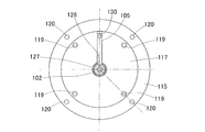
- 10 is a cross-sectional view of the one-axis linear motion mechanism
- FIG. 11 is a cross-sectional view taken along line XI-XI of FIG. 10
- FIG. 12 is a right side view of the one-axis linear motion mechanism.
- FIG. 10 shows a cross section taken along the line X-O4-X of FIG.
- the one-axis linear motion mechanism 6 converts the rotation of the hollow motor 101 into a linear motion, and advances and retracts the slide shaft 102 in the axial direction.
- the one-axis linear motion mechanism 6 includes a hollow motor 101, a nut 103, a slide shaft 102, a pair of locking members 104 and 105, and a rotation detection unit 106.
- the hollow motor 101 has a stator 110, a coil 111, a permanent magnet 112, and a hollow shaft 113 which is a rotor.
- the energization of the coil 111 is controlled by a control device (not shown).
- the stator 110 constitutes a housing of the one-axis linear motion mechanism 6, and includes a stator main body 114 at an axial center, a flange forming member 115 fixed to one end face of the stator main body 114, and a stator It has a pair of lids 116 and 117 fixed to the end face of the main body 114 and the flange forming member 115, respectively.
- the flange forming member 115 and the lid 116 are fixed to the stator body 114 by fixing bolts 118, and the lid 117 is fixed to the stator body 114 by fixing bolts 119.
- the flange forming member 115 has a flange portion 115a on the outer periphery, and the flange portion 115a is provided with a through hole 120 for attaching the one-axis linear motion mechanism 6 to another device.
- the inner circumferential portions of the lids 116 and 117 constitute radial bearing portions 121 and 122 which support the slide shaft 102 rotatably and axially movably.
- the radial bearings 121 and 122 are formed of resin.
- a coil 111 is disposed on the inner periphery of the stator main body 114, and a permanent magnet 112 is disposed opposite to the inner periphery of the coil 111.
- the permanent magnet 112 is fixed to the outer peripheral surface of the hollow shaft 113. Both ends of the hollow shaft 113 are rotatably supported by a pair of rolling bearings 123 and 124 respectively installed on the flange forming member 115 and the stator main body 114.
- the nut 103 is fixed to the inner diameter portion of the hollow shaft 113.
- a female screw 125 is formed on one axial end side (left side in FIG. 10) of the nut 103, and a radial bearing portion rotatably and axially movably supports the slide shaft 102 on the other axial end side (right side in FIG. 10) It is said to be 126.
- the nut 103 is made of resin and integrated with the hollow shaft 113 made of metal by insert molding.
- a convex portion 103 a provided on the outer peripheral surface of the nut 103 is in a shape of biting into the inner peripheral surface of the hollow shaft 113, and the nut 103 and the hollow shaft 113 are firmly integrated.
- the resin used for the nut 103 and the radial bearing portions 121 and 122 of the lids 116 and 117 has excellent slidability with the slide shaft 102 and is lower in hardness than the metal constituting the slide shaft 102 Desired.
- resin materials that satisfy such requirements include fluorine-based resin compositions and ultra-high molecular weight polyethylene resin compositions.
- the fluorine-based resin composition contains a fluorine-based resin as a main component.
- a fluorine-based resin polytetrafluoroethylene resin (abbreviated as PTFE), tetrafluoroethylene-hexafluoropropylene copolymer resin (abbreviated as FEP), tetrafluoroethylene-perfluoroalkyl vinyl ether copolymer resin (abbreviated as PFE), Examples thereof include ethylene-tetrafluoroethylene copolymer resin, polychlorotrifluethylene resin, and ethylene-chlorofluoroethylene copolymer resin. These may be resins consisting of two or more copolymers, terpolymers, etc., each alone or at a polymerization ratio of, for example, 1:10 to 10: 1 of the fluorine-based resin monomers.
- the slide shaft 102 is an axially longer shaft than the stator 110 forming the housing, and a male screw 127 is formed between the axial ends of the outer periphery.
- the male screw 127 is screwed to the female screw 125 of the nut 103.
- a locking groove 128 extending in the axial direction is formed between both axial ends. That is, the male screw 127 and the locking groove 128 are formed at the same axial position, and a part of the male screw 127 in the circumferential direction is notched by the locking groove 128.
- the number of the locking grooves 128 is one, but it may be dispersed in the circumferential direction.
- the locking members 104 and 105 are fixed to the lids 116 and 117 by fixing bolts 130 and 130, respectively, and the tips thereof are inserted into the locking grooves 128 of the slide shaft 102. Thereby, the slide shaft 102 is prevented from rotating.
- the locking groove 128 and the locking members 104 and 105 constitute a locking mechanism.
- the locking mechanism may have other configurations. For example, the balls may roll in the locking grooves 128.
- the rotation detecting means 106 has a magnetic encoder 131 provided on the hollow shaft 113 and a magnetic sensor 132 provided on the stator main body 114, and these magnetic encoder 131 and magnetic sensor 132 face each other in the axial direction. There is.
- the magnetic sensor 132 is connected to the controller.
- the 1-axis linear motion mechanism 6 configured as described above operates as follows. Under the control of the control device (not shown), when the coil 111 is energized, the hollow shaft 113 of the hollow motor 101 is rotated, and the nut 103 provided on the hollow shaft 113 is rotated. The slide shaft 102 screwed to the nut 103 also tries to rotate, but since the slide shaft 102 is locked by the locking members 104 and 105 engaged with the locking groove 128, it can not be rotated, and can not rotate. Advance to The rotation of the hollow shaft 113 is detected by the rotation detection means 106, and the detection signal is sent to the control device.
- the axial linear movement mechanism 6 can be configured to be compact in the axial direction.
- the slide shaft 102 can be rotatably and axially movably supported only by the radial bearing portion 126 of the nut 103. However, by providing the radial bearing portions 121 and 122 also on the stator 110, the support of the slide shaft 102 is achieved. Stabilize. By providing the additional radial bearing portions 121 and 122 in the stator 110, the support of the slide shaft 102 can be stabilized without changing the axial length of the one-axis linear motion mechanism 6.
- the slidability with respect to the slide shaft 102 is good. Specifically, the slidability between the internal thread 125 of the nut 103 and the external thread 127 of the slide shaft 102 is good, and the sliding between the radial bearing portion 126 of the nut 103 and the outer peripheral surface of the slide axis 102 (thread of the external thread 127) Mobility is good. Similarly, since the radial bearing portions 121 and 122 of the lids 116 and 117 are also made of resin, the slidability between the radial bearing portions 121 and 122 and the outer peripheral surface of the slide shaft 102 is also good. For this reason, it is not necessary to supply a lubricant to each said sliding part, and the whole structure of the 1 axis
- two locking bodies 104 and 105 for locking the slide shaft 102 are respectively provided at both axial ends of the stator 110. As described above, by locking the slide shaft 102 with the plurality of axially spaced locking members 104 and 105, rattling does not easily occur when the rotational direction of the nut 103 is reversed, and a stable operation is performed. be able to.
- An end effector mounting member 140 is provided at one end of the slide shaft 102.
- the end effector mounting member 140 has a screw hole 141 for mounting the end effector, and is fixed to the slide shaft 102 by a fixing bolt 142. Further, at the other end of the slide shaft 102, a retaining member 142 is fixed by a fixing bolt 143.
- the one-axis linear motion mechanism 6 is fixed to the tip member 70 of the parallel link mechanism 5 by a bolt inserted through the through hole 120 of the flange portion 115a. Then, an end effector according to the work content is attached to the end effector attachment member 140.
- the first arm 3 and the second arm 4 are rotated to determine the planar view position of the end effector 300 and the parallel link mechanism 5 is used. It operates to determine the attitude of the end effector 300.
- the attitude of the end effector 300 is determined by the rotational position around the axial center C3 and the attitude of the distal end side link hub 33.
- the tip of the article 301 is positioned near the exit of the hole 302a of the work 302, and the central axis of the article 301 calculated by calculation under control of the articulated robot 1 coincides with the central axis of the actual hole 302a.
- the actuator 13 for rotating the parallel link mechanism and the actuator 31 for attitude control are in a clutch connection state.
- the end effector 300 When the position and posture of the end effector 300 are determined, the end effector 300 is moved by the one-axis linear motion mechanism 6 as shown in FIG. 13B, and the article 301 is inserted into the hole 302 a of the work 302. At this time, the parallel link mechanism rotating actuator 13 and the attitude control actuator 31 are set in the clutch disengaged state so that the reverse input torque is not transmitted to the drive motor 150 of these actuators 13 and 31. Thereby, the parallel link mechanism 5 can freely move in response to the external force.
- the articulated robot 1 advances and retracts the end effector 300 in one axial direction by the one-axis linear motion mechanism 6. Therefore, the difficult task of inserting the article 301 gripped by the end effector 300 into the hole 302a of the work 302 provided at the fixed position can be performed only by operating the 1-axis linear motion mechanism 6, and control is easy. is there.
- the one-axis linear motion mechanism 6 a slide screw mechanism which may be structurally deviated in the feed direction as in this embodiment.
- the slide screw mechanism is a relatively lightweight and simple structure, and can be manufactured at low cost.
- FIG. 14 shows an articulated robot 1 provided with a lifting and lowering mechanism 8 for lifting and lowering the first arm 3 in the first embodiment.
- the elevating mechanism 8 has a support 180 fixed to the ceiling surface, and a linear actuator 181 is provided on the support 180 so that its advancing and retreating direction is in the vertical direction, and the elevating member 182 is fixed to the linear actuator 181 There is.
- the first arm 3 is rotatably supported by the raising and lowering member 182 about an axial center C1 in the vertical direction.
- the first arm rotation actuator 11 is provided inside the lift member 182.
- the lifting mechanism 8 is covered by a cover 183.
- the cover 183 includes a fixing portion 183 a fixed to the ceiling surface, and an elevating portion 183 b attached to the elevating member 182 and sliding in the vertical direction with respect to the fixing member 183.
- the elevating mechanism 8 By providing the elevating mechanism 8 in this manner, the upper and lower positions of the end effector can be arbitrarily changed, so that the working application of the articulated robot 1 can be expanded.
- the other configuration is the same as that of the first embodiment.
- FIG. 15 shows an articulated robot 1 in which the configuration of the link actuation device 30 is different from that of the first embodiment.
- the configuration of the link actuation device 30 is different from that of the first embodiment.
- FIG. 16 is a front view showing the parallel link mechanism and a part of the attitude control actuator with the part omitted.
- the link actuation device 30 of this modification 2 also has the parallel link mechanism 5 and the attitude control actuator 31 as in the first embodiment. Further, in the parallel link mechanism 5, the link hub 33 on the distal end side is connected to the proximal end link hub 32 via the three link mechanisms 34 so as to be changeable in posture.
- the point at which the link actuation device 30 of this modification 2 differs from the first embodiment is that each attitude control actuator 31 has its output shaft 31 a at the proximal end side with the link hub 32 at the proximal end side, as described later.
- the rotation center 22 of the rotation pair portion of the end link member 35 is disposed so as to be coaxial with the axis.
- FIG. 17A is a cross-sectional view taken along line XVII-PA-XVII in FIG. 16, and FIG. 17B is a partially enlarged view thereof.
- the rotary shaft 22 is rotatably supported by the rotary shaft connecting members 21 of the link hub 32 on the proximal end side, and one end of the end link member 35 on the proximal side is connected to the rotary shaft 22.
- the rotation shaft 22 of this modification 2 has a large diameter portion 22a, a small diameter portion 22b and an external thread portion 22c, and is rotatably supported by the rotation shaft connecting member 21 via the two bearings 23 at the small diameter portion 22b.
- the bearing 23 is, for example, a ball bearing such as a deep groove ball bearing or an angular ball bearing.
- bearings 23 are installed in a fitted state in the inner diameter groove 24 provided in the rotary shaft connection portion 21 and fixed by a method such as press fitting, bonding, caulking or the like.
- the types and installation methods of the bearings provided in the other rotation pairs are the same.
- the rotation shaft 22 is coaxially arranged with the output shaft 31 a of the posture control actuator 31 at the large diameter portion 22 a.
- the arrangement structure will be described later.
- one end of a proximal end side end link member 35 is connected to the rotation shaft 22 so as to rotate integrally with the rotation shaft 22. That is, the rotary shaft connecting member 21 is disposed in the notch 25 formed at one end of the end link member 35 on the proximal end side, and the small diameter portion 22 b of the rotary shaft 22 is both sides of the notch 25.
- the inner ring of the bearing 23 is inserted through the through holes respectively formed in the inner and outer rotary shaft support portions 26 and 27.
- the end link member 35 on the proximal end side and the output shaft 31a of the attitude control actuator 31 are fixed by bolts 29 via a spacer 28 fitted to the outer periphery of the large diameter portion 22a of the rotation shaft 22,
- a nut 80 is screwed to the male screw portion 22 c of the rotary shaft 22 which protrudes from the rotary shaft support 27.
- Spacers 81 and 82 are interposed between the inner ring of the bearing 23 and the pair of rotary shaft support portions 26 and 27, and a preload is applied to the bearing 23 when the nut 80 is screwed on.
- the attitude control actuator 31 is disposed coaxially with the rotation shaft 22 and is fixed to the upper surface of the base end member 20 of the link hub 32 on the base end side by a motor fixing member 83.
- the attitude control actuator 31 is also an end effector operation mechanism actuator having the configuration shown in FIG. 8A, as in the first embodiment.
- the tip end surface of the output shaft 31a is a planar flange surface 84 orthogonal to the center line of the output shaft 31a.
- the output shaft 31 a is connected to the rotary shaft support portion 26 of the end link member 35 on the proximal end side with a bolt 29 via the spacer 28.
- the large diameter portion 22a of the rotary shaft 22 constitutes a rotation pair of the link hub 32 on the proximal end side and the end link member 35 on the proximal end side, and the large diameter portion 22a has an inner diameter provided on the output shaft 31a.
- the groove 87 is fitted.
- the same operation and effect as in the case of using the link actuation device 30 of the first embodiment can be obtained.
- a rotational two degree of freedom mechanism other than the parallel link mechanism 5 may be adopted as long as the attitude of the end effector can be changed.
- Second Embodiment 18A and 18B respectively show a plan view and a front view of an articulated robot according to a second embodiment.
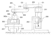
- the articulated robot 201 includes an elevation mechanism 208 provided on a support 202 fixed to the ground, and a first arm 203 supported by the elevation mechanism 208 and rotatably supported about an axial center C1 in the vertical direction.
- a second arm 204 rotatably supported around a vertical axis C2 at the tip of the first arm 203, and an end effector provided at the tip of the second arm 204 and rotating around a vertical axis C3.
- an end effector rotation mechanism 205 as an end effector operation mechanism.
- An end effector 300 for gripping an article is attached to the tip of a rotation shaft extending downward from the end effector rotation mechanism 205.
- the first arm 203 is rotated about the axis C1 by a first arm actuator 211 installed inside the support 202.
- the second arm 204 is rotated about the axis C2 by a second arm actuator 212 installed on the top end of the first arm 203.
- the first arm actuator 211 and the second arm actuator 212 are configured as shown in FIG. 8A, FIG. 8B, and FIG. 9 similarly to the end effector operation mechanism actuator in the first embodiment, and are on the output side And a clutch mechanism capable of interrupting the transmission of the reverse input torque applied to the rotary drive unit.
- a work transfer device 220 for moving the work 302 in a fixed direction along the horizontal surface is provided below the end effector rotation mechanism 205.
- the work transfer device 220 is, for example, a belt conveyor device.
- the work transfer device 220 is provided with a work loading stand 221 at a predetermined interval, and the work 302 placed on the work loading stand 221 is transferred.
- the workpiece 302 is positioned on the workpiece platform 221 by a plurality of positioning pins 222.
- the method of operating the articulated robot 1 includes an upward hole of the workpiece 302 in which the workpiece 301 gripped by the end effector 300 is transported by the workpiece transport device 220.
- the case of insertion in 302 a will be described as an example.
- the article 301 is cylindrical, and the hole 302 a of the work 302 is cylindrical with an inner diameter slightly larger than the outer diameter of the article 301.
- the first arm 203 and the second arm 204 are rotationally operated to put the end effector 300 on standby above the predetermined work position.
- the central axis of the article 301 gripped by the end effector 300 is positioned so as to coincide with the central axis of the hole 302 a of the workpiece 302 at the predetermined work position P.
- the first arm rotation actuator 211 and the second arm rotation actuator 212 are in a clutch connection state.
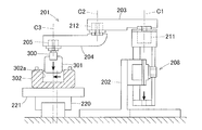
- the work transfer device The position of the hole 302 a of the article 301 and the work 302 may be shifted due to the vibration of 220 or the like.
- the first arm actuator 211 and the second arm actuator 212 are in the clutch disengaged state, and the first arm 203 and the second arm 204 can move freely. Therefore, even if the central axis of the article 301 and the central axis of the hole 302a are slightly deviated, as shown in FIGS.
- the first arm 211 and the second arm moves. Thereby, the displacement can be absorbed and the article 301 can be inserted into the hole 302 a of the work 302.
- the work transfer apparatus 220 a relatively inexpensive apparatus, for example, a belt conveyor apparatus, which does not require much accuracy with respect to the position of the work 302 can be used.
Landscapes
- Engineering & Computer Science (AREA)
- Robotics (AREA)
- Mechanical Engineering (AREA)
- Manipulator (AREA)
Abstract
多関節ロボット(1)は、鉛直方向の軸心(C1)回りに回転自在な第一アーム(3)と、鉛直方向の軸心(C2)回りに回転自在な第二アーム(4)と、エンドエフェクタを鉛直方向の軸心回りに回転および姿勢変更のいずれか一方または両方を可能に支持するエンドエフェクタ作動機構(7)とを備える。第一アーム用アクチュエータ(11)、第二アーム用アクチュエータ(12)およびエンドエフェクタ作動機構用アクチュエータ(13,31)のうちの少なくとも一つのアクチュエータは、出力側に加えられた逆入力トルクの回転駆動部への伝達を遮断可能なクラッチ機構を具備する。
Description
この出願は、2017年9月29日出願の特願2017-189684の優先権を主張するものであり、その全体を参照により本願の一部をなすものとして引用する。
この発明は、各種産業分野において物品の加工や移載、組立等に用いられる多関節ロボット、およびその操作方法に関する。
上記多関節ロボットの一種で、水平方向にアームが動作する水平多関節ロボット、いわゆるスカラロボットがある(例えば特許文献1~3)。また、複数の回転関節を有し、人の腕に近い動作をするロボットアーム型の多関節ロボットもある(例えば特許文献4、5)。
本件出願人は、スカラロボットにおいて、図21に示すように、第一アーム3と第二アーム4とを有し、第二アーム4の先端にパラレルリンク機構5を設けたものを提案している。パラレルリンク機構5は、回転機構310により軸心O3回りに回転可能、かつ昇降機構311により軸心O3に沿って昇降可能に設置されている。この提案の構成によると、パラレルリンク機構5に取り付けられたエンドエフェクタ300を任意の角度に姿勢変更することが可能となり、エンドエフェクタ300により複雑な作業を行うことができる。
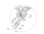
しかしながら、上記提案の構成では、例えば、図21に示すように、エンドエフェクタ300に把持された物品301を固定位置に設けられたワーク302の斜めの穴302aに挿入するような作業が難しい。つまり、物品301を穴302aに挿入するには、物品301の中心軸と穴302aの中心軸とが一致するようにパラレルリンク機構5によりエンドエフェクタ300の姿勢を保ちながら、エンドエフェクタ300を物品301の中心軸および穴302aの中心軸に沿って斜めに移動させる必要がある。そのためには、第一アーム3、第二アーム4、パラレルリンク機構5、回転機構310、および昇降機構311の動作を細かく制御しなければならず、制御が難しい。
そこで、本件出願人は、上記提案の構成に加えて、パラレルリンク機構5に1軸直動機構を搭載し、この1軸直動機構にエンドエフェクタ300を取り付けることを試みた。1軸直動機構を設けると、第一アーム3、第二アーム4、パラレルリンク機構5、回転機構310、および昇降機構311は作動させずに、1軸直動機構でエンドエフェクタ300を進退させるだけで、物品301をワーク302の穴302aに挿入することができるので、制御が簡単になる。
スカラロボットに使用する1軸直動機構としては、軽量化、簡素化、および低コスト化の観点から、すべりねじ構造の採用を検討しているが、すべりねじ構造であると、そのすべりねじ部のガタの影響が懸念される。つまり、1軸直動機構による物品301の送り方向と、穴302aの向きとにずれが生じることにより、物品301が穴302aの内壁に当って、物品301を穴302aにスムーズに挿入できない恐れがある。1軸直動機構としてすべりねじ構造を採用するには、ガタの影響について対策を講じる必要がある。
また、本件出願人は、ベルトコンベアによって搬送されるワークの上向きの穴に物品を挿入する作業を、スカラロボットを用いて行うことを試みている。具体的には、スカラロボットのいずれかの箇所に昇降機構を設け、この昇降機構により物品把持用のエンドエフェクタを下降させて、ベルトコンベア上のワークの穴に物品を挿入させる。しかしながら、ベルトコンベアによる搬送では、搬送時の振動によってワークが動くことがある。ワークが動くと、物品とワークの位置関係にずれが生じ、ワークの穴に物品を挿入させることができなくなる。
特許文献1に、スカラロボットを用いた物品の組立において、スカラロボットが把持した物品をワークに組み込む際のミスを無くすことができるロボット組立装置が提案されている。このロボット組立装置も、上記同様に、スカラロボットが把持したピン(物品)を、各アームを作動させて所定の平面視位置へ移動させた後、アームごとピンを下降させて、作業台上のワークの穴にピンを挿入する。この提案では、作業台を、水平面に沿ってX軸方向およびY軸方向に移動可能としている。これにより、ワークの穴にピンを挿入する際に、ワークの穴とピンとの間にずれが生じている場合、ピンをZ軸方向に下げて行くに従い、ワークがピンに合わせて動くことで位置ずれを吸収することができる。
しかしながら、特許文献1の構成は、ピンに合わせて作業台が動くように作業台を支持する機構が必要であるので、装置全体が高価になるという課題がある。
この発明の目的は、エンドエフェクタに把持された物品と固定位置に設けられたワークと接触させて行う作業を、物品とワークとの位置ずれの影響を受けることなく、精度良く行うことができる多関節ロボットを提供することである。
この発明の他の目的は、物品をワークの穴に挿入させる作業を、物品とワークとの位置ずれの影響を受けることなく行わせることができる上記多関節ロボットの操作方法を提供することである。
この発明の他の目的は、物品をワークの穴に挿入させる作業を、物品とワークとの位置ずれの影響を受けることなく行わせることができる上記多関節ロボットの操作方法を提供することである。
この発明の多関節ロボットは、支持体に設けられ鉛直方向の軸心回りに回転自在な第一アームと、この第一アームを回転させる第一アーム用アクチュエータと、前記第一アームの先端に設けられ鉛直方向の軸心回りに回転自在な第二アームと、この第二アームを回転させる第二アーム用アクチュエータと、前記第二アームの先端に設けられエンドエフェクタを鉛直方向の軸心回りに回転および姿勢変更のいずれか一方または両方を可能に支持するエンドエフェクタ作動機構と、このエンドエフェクタ作動機構を作動させるエンドエフェクタ作動機構用アクチュエータとを備え、
前記第一アーム用アクチュエータ、前記第二アーム用アクチュエータ、および前記エンドエフェクタ作動機構用アクチュエータのうちの少なくとも一つのアクチュエータは、出力側に加えられた逆入力トルクの回転駆動部への伝達を遮断可能なクラッチ機構を具備する。
前記第一アーム用アクチュエータ、前記第二アーム用アクチュエータ、および前記エンドエフェクタ作動機構用アクチュエータのうちの少なくとも一つのアクチュエータは、出力側に加えられた逆入力トルクの回転駆動部への伝達を遮断可能なクラッチ機構を具備する。
この多関節ロボットは、通常、クラッチ機構を接続状態としておく。この状態で、第一アームおよび第二アームを回転させてエンドエフェクタの平面視位置を変更し、かつエンドエフェクタ作動機構を作動させてエンドエフェクタの回転および姿勢変更のいずれか一方または両方を行いつつ、エンドエフェクタにより作業を行う。その際、エンドエフェクタに外力が加わった場合、第一アーム用アクチュエータ、第二アーム用アクチュエータ、およびエンドエフェクタ作動機構用アクチュエータのうちの少なくとも一つのアクチュエータが具備するクラッチ機構を遮断状態にする。これにより、そのアクチュエータの回転駆動部へ逆入力トルクが伝達されないようなる。このため、クラッチ機構を具備するアクチュエータで動作させる動作対象、つまり第一アーム、第二アーム、およびエンドエフェクタ作動機構のいずれかが自由に動けるようになり、動作対象が固定されていることによる弊害を排除できる。
この発明において、前記エンドエフェクタ作動機構は、前記第二アームの先端に設けられた基端側部材に対して先端側部材を姿勢変更させる回転2自由度機構と、この回転2自由度機構の前記先端側部材に設けられてエンドエフェクタを1軸方向に進退させる1軸直動機構とを有し、前記エンドエフェクタ作動機構用アクチュエータは前記回転2自由度機構を作動させるものであり、このエンドエフェクタ作動機構用アクチュエータに前記クラッチ機構が設けられていてもよい。
この構成であると、エンドエフェクタ作動機構として、回転2自由度機構と1軸直動機構とを有するので、回転2自由度機構によりエンドエフェクタの姿勢を任意の角度にした状態で、1軸直動機構によりエンドエフェクタを1軸方向に進退させることができる。これにより、例えば、エンドエフェクタが把持した物品を固定位置に設けられたワークの穴に挿入する作業を、1軸直動機構を作動させるだけで行うことができるので、制御が容易である。
エンドエフェクタの姿勢を変更する際には、エンドエフェクタ作動機構用アクチュエータをクラッチ接続状態にして、回転2自由度機構を作動させる。エンドエフェクタの位置および姿勢が決まり、1軸直動機構を作動させて物品をワークの穴に挿入する際には、エンドエフェクタ作動機構用アクチュエータをクラッチ遮断状態にして、同アクチュエータの回転駆動部へ逆入力トルクが伝達されないようにする。これにより、回転2自由度機構が、外力に応じて自由に動けるようなる。このため、1軸直動機構の構造上の問題で、物品の移動方向が穴の中心軸の方向に対して少しずれていたとしても、穴の内壁から受ける力に応じて回転2自由度機構が動く。これにより、ずれを吸収して、物品をワークの穴に挿入することができる。
このように1軸直動機構による送り方向の少しのずれを許容することができるので、1軸直動機構として、構造的に送り方向のずれが生じる可能性のある機構、例えばすべりねじ機構を使用することができる。すべりねじ機構は、比較的に軽量かつ簡素な構造であり、低コストで製作することができる。
前記回転2自由度機構は、前記基端側部材である基端側のリンクハブに対し前記先端側部材である先端側のリンクハブが3組以上のリンク機構を介して姿勢を変更可能に連結され、前記各リンク機構は、それぞれ前記基端側のリンクハブおよび前記先端側のリンクハブに一端が回転可能に連結された基端側および先端側の端部リンク部材と、これら基端側および先端側の端部リンク部材の他端に両端がそれぞれ回転可能に連結された中央リンク部材とを有するパラレルリンク機構であってもよい。その場合、前記3組以上のリンク機構のうちの2組以上のリンク機構に、前記基端側のリンクハブに対して前記先端側のリンクハブの姿勢を任意に変更させる前記エンドエフェクタ作動機構用アクチュエータが設けられている。
パラレルリンク機構は、基端側のリンクハブと、先端側のリンクハブと、3組以上のリンク機構とで、基端側のリンクハブに対し先端側のリンクハブが直交2軸回りに回転自在な2自由度機構を構成する。この2自由度機構は、コンパクトでありながら、先端側のリンクハブの可動範囲を広くとれる。このため、エンドエフェクタを任意の姿勢に変更することができる。また、パラレルリンク機構はコンパクトであるので、第一アームおよび第二アームにかかる負担が小さく、これらアームおよびその支持部の剛性を低く抑えることができる。3組以上のリンク機構のうちの2組以上のリンク機構にエンドエフェクタ作動機構用アクチュエータが設けられていると、先端側のリンクハブの姿勢を確定することができる。
この発明の第1の多関節ロボットの操作方法は、エンドエフェクタに把持された物品を固定位置に設けられたワークの穴に挿入する場合における前記多関節ロボットの操作方法である。具体的には、前記第一アーム、前記第二アーム、および前記エンドエフェクタ作動機構を作動させて、前記物品の中心軸が前記ワークの穴の中心軸と一致し、かつ前記物品の先端が前記ワークの穴の入口付近に位置するように位置決めした後、前記エンドエフェクタ作動機構用アクチュエータの前記クラッチ機構を遮断した状態で、前記1軸直動機構を作動させて前記物品を前記ワークの穴に挿入する。
この多関節ロボットの操作方法によると、1軸直動機構によりエンドエフェクタを1軸方向に移動させて、エンドエフェクタに把持された物品をワークの穴に挿入する際に、クラッチ機構を遮断状態にして回転2自由度機構が自由に動けるようする。これにより、物品の移動方向が穴の中心軸の方向に対して少しずれていたとしても、穴の内壁から受ける力に応じて回転2自由度機構が動く。ことれより、ずれを吸収して、物品をワークの穴に挿入することができる。
この発明において、前記第一アーム、前記第二アーム、および前記エンドエフェクタ作動機構の少なくともいずれか一つを昇降させる昇降機構を有し、前記第一アーム用アクチュエータおよび前記第二アーム用アクチュエータに前記クラッチ機構が設けられていてもよい。
この構成によると、第一アームおよび第二アームを回転させてエンドエフェクタの平面視位置を決め、昇降機構によりエンドエフェクタを昇降させて作業を行う。第一アームおよび第二アームを回転作動させてエンドエフェクタの平面視位置を決めるときには、第一アーム用アクチュエータおよび第二アーム用アクチュエータの各クラッチ機構を接続状態とする。
例えば、エンドエフェクタが把持した物品を固定位置に設けられたワークの穴に挿入する作業の場合、昇降機構によりエンドエフェクタを昇降させるとき、第一アーム用アクチュエータおよび第二アーム用アクチュエータの各クラッチ機構を遮断状態にして、アクチュエータの回転駆動部へ逆入力トルクが伝達されないようにする。これにより、第一アームおよび第二アームが自由に動けるようなる。このため、何らかの理由で物品の中心軸と穴の中心軸の平面視位置とが少しずれていたとしても、穴の内壁から受ける力に応じて第一アームおよび第二アームが動く。これにより、ずれを吸収して、物品をワークの穴に挿入することができる。
前記エンドエフェクタ作動機構の下方に、前記エンドエフェクタの作業対象となるワークを水平面に沿って一定方向に移動させるワーク搬送装置が設けられていてもよい。ワーク搬送装置が設けられていると、ワークを作業位置まで効率良く送ることができるので、作業能率が向上する。前述のように、ワークの位置が作業位置から多少ずれていても、そのずれを吸収して作業を行うことができるので、ワーク搬送装置として、搬送精度がさほど要求されない比較的安価な装置、例えばベルトコンベア装置を使用することができる。
この発明の第2の多関節ロボットの操作方法は、エンドエフェクタに把持された物品を前記ワーク搬送装置で搬送されるワークの上向きの穴に挿入する場合における前記多関節ロボットの操作方法である。具体的には、前記第一アームおよび前記第二アームを作動させて、前記物品の中心軸が前記ワークの穴の中心軸と一致するように位置決めした後、前記第一アーム用アクチュエータおよび前記第二アーム用アクチュエータの各クラッチ機構を遮断した状態で、前記昇降機構を作動させて前記物品を前記ワークの穴に挿入する。
この多関節ロボットの操作方法によると、昇降機構によりエンドエフェクタを下向きに移動させて、エンドエフェクタに把持された物品をワークの穴に挿入する際に、クラッチ機構を遮断状態にして第一アームおよび第二アームが自由に動けるようにする。これにより、物品の中心軸と穴の中心軸の方向とが少しずれていたとしても、穴の内壁からの受ける力に応じて第一アームおよび第二アームが動く。これにより、ずれを吸収して、物品をワークの穴に挿入することができる。
請求の範囲および/または明細書および/または図面に開示された少なくとも2つの構成のどのような組合せも、この発明に含まれる。特に、請求の範囲の各請求項の2つ以上のどのような組合せも、この発明に含まれる。
本発明は、添付の図面を参考にした以下の好適な実施形態の説明からより明瞭に理解されるであろう。しかしながら、実施形態および図面は単なる図示および説明のためのものであり、本発明の範囲を定めるために利用されるべきものではない。本発明の範囲は添付の請求の範囲によって定まる。添付図面において、複数の図面における同一の部品番号は、同一または相当部分を示す。
この発明の第1の実施形態にかかる多関節ロボットの概略構成図である。
同多関節ロボットの平面図である。
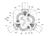
同多関節ロボットのパラレルリンク機構と姿勢制御用アクチュエータの一部を省略して示す正面図である。
同パラレルリンク機構の一状態を示す正面図である。
同パラレルリンク機構の異なる状態を示す正面図である。
図3のVI-PA-VI断面図である。
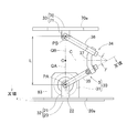
同パラレルリンク機構の1つのリンク機構を直線で表現した図である。
同多関節ロボットの姿勢制御用アクチュエータの主要部を断面で示す図である。
同多関節ロボットの姿勢制御用アクチュエータの主要部の部分拡大図である。
同多関節ロボットの姿勢制御用アクチュエータの主要部の図8Bとは異なる状態の部分拡大図である。
図8AのIX-IX断面図である。
同多関節ロボットの1軸直動機構の断面図である。
図10のXI-XI断面図である。
同1軸直動機構の右側面図である。
同多関節ロボットの使用状態を示す概略構成図である。
同多関節ロボットの異なる状態を示す部分図である。
この発明の第1の実施形態にかかる多関節ロボットの変形例の概略構成図である。
この発明の第1の実施形態にかかる多関節ロボットの別の変形例の概略構成図である。
同多関節ロボットのパラレルリンク機構と姿勢制御用アクチュエータの一部を省略して示す正面図である。
図16のXVII-PA-XVII断面図である。
図17Aの部分拡大図である。
この発明の第2の実施形態にかかる多関節ロボットの平面図である。
同多関節ロボットの正面図である。
同多関節ロボットの異なる状態を示す平面図である。
同多関節ロボットの異なる状態を示す正面図である。
同多関節ロボットのさらに異なる状態を示す平面図である。
同多関節ロボットのさらに異なる状態を示す正面図である。
提案の多関節ロボットの概略構成を示す図である。
以下、図面と共にこの発明の実施形態を説明する。
[第1の実施形態]
図1は第1の実施形態にかかる多関節ロボットの概略構成を示す図で、図2はその平面図である。この多関節ロボット1は、天井面に固定の支持体2に設けられ鉛直方向の軸心C1回りに回転自在に支持された第一アーム3と、この第一アーム3の先端に鉛直方向の軸心C2回りに回転自在に支持された第二アーム4と、この第二アーム4の先端に鉛直方向の軸心C3回りに回転自在に支持されたパラレルリンク機構5と、このパラレルリンク機構5に搭載された1軸直動機構6とを備える。パラレルリンク機構5は、回転2自由度機構の一形態である。パラレルリンク機構5と1軸直動機構6とで、エンドエフェクタ作動機構7が構成されている。
[第1の実施形態]
図1は第1の実施形態にかかる多関節ロボットの概略構成を示す図で、図2はその平面図である。この多関節ロボット1は、天井面に固定の支持体2に設けられ鉛直方向の軸心C1回りに回転自在に支持された第一アーム3と、この第一アーム3の先端に鉛直方向の軸心C2回りに回転自在に支持された第二アーム4と、この第二アーム4の先端に鉛直方向の軸心C3回りに回転自在に支持されたパラレルリンク機構5と、このパラレルリンク機構5に搭載された1軸直動機構6とを備える。パラレルリンク機構5は、回転2自由度機構の一形態である。パラレルリンク機構5と1軸直動機構6とで、エンドエフェクタ作動機構7が構成されている。
第一アーム3は、支持体2の内部に設置された第一アーム用アクチュエータ11により軸心C1回りに回転させられる。第二アーム4は、第一アーム3の先端上面部に設置された第二アーム用アクチュエータ12により軸心C2回りに回転させられる。これら第一アーム用アクチュエータ11および第二アーム用アクチュエータ12は、減速機付きのロータリアクチュエータである。
パラレルリンク機構5は、パラレルリンク機構回転用アクチュエータ13によって軸心C3回りに回転させられ、かつ姿勢制御用アクチュエータ31によって作動させられる。これらパラレルリンク機構回転用アクチュエータ13および姿勢制御用アクチュエータ31は、エンドエフェクタ作動機構7を作動させる「エンドエフェクタ作動機構用アクチュエータ」を構成し、いずれも出力側に加えられた逆入力トルクの回転駆動部への伝達を遮断可能なクラッチ機構を具備する。
<パラレルリンク機構>
図3は、パラレルリンク機構5および姿勢制御用アクチュエータ31を示す正面図である。これらパラレルリンク機構5と姿勢制御用アクチュエータ31とでリンク作動装置30を構成する。また、図4および図5は、パラレルリンク機構5だけを取り出して表わした図であり、互いに異なる状態を示している。なお、図3~図5では、図1に示す設置状態と上下反転して示されている。
図3は、パラレルリンク機構5および姿勢制御用アクチュエータ31を示す正面図である。これらパラレルリンク機構5と姿勢制御用アクチュエータ31とでリンク作動装置30を構成する。また、図4および図5は、パラレルリンク機構5だけを取り出して表わした図であり、互いに異なる状態を示している。なお、図3~図5では、図1に示す設置状態と上下反転して示されている。
パラレルリンク機構5では、基端側のリンクハブ32に対し先端側のリンクハブ33が3組のリンク機構34を介して姿勢変更可能に連結されている。基端側のリンクハブ32は、第二アーム4の先端に設けられた「基端側部材」を構成し、先端側のリンクハブ33は、パラレルリンク機構5(回転2自由度機構)により基端側部材に対して姿勢変更される「先端側部材」を構成する。なお、図3では、1組のリンク機構34のみが示されている。リンク機構34の数は、4組以上であってもよい。
各リンク機構34は、基端側の端部リンク部材35、先端側の端部リンク部材36、および中央リンク部材37で構成され、4つの回転対偶からなる4節連鎖のリンク機構である。基端側および先端側の端部リンク部材35,36はL字状をなし、一端がそれぞれ基端側のリンクハブ32および先端側のリンクハブ33に回転自在に連結されている。中央リンク部材37は、両端に基端側および先端側の端部リンク部材35,36の他端がそれぞれ回転自在に連結されている。
パラレルリンク機構5は、2つの球面リンク機構を組み合わせた構造であって、基端側と先端側において、リンクハブ32,33と端部リンク部材35,36の各回転対偶、および端部リンク部材35,36と中央リンク部材37の各回転対偶の中心軸が、それぞれの球面リンク中心PA,PB(図3)で交差している。
また、基端側と先端側において、リンクハブ32,33と端部リンク部材35,36の各回転対偶とそれぞれの球面リンク中心PA,PBからの距離も同じであり、端部リンク部材35,36と中央リンク部材37の各回転対偶とそれぞれの球面リンク中心PA,PBからの距離も同じである。端部リンク部材35,36と中央リンク部材37との各回転対偶の中心軸は、ある交差角γ(図3)を持っていてもよいし、平行であってもよい。
図6は図3のVI-PA-VI断面図である。同図に、基端側のリンクハブ32と基端側の端部リンク部材35の各回転対偶の中心軸O1と、中央リンク部材37と基端側の端部リンク部材35の各回転対偶の中心軸O2と、基端側の球面リンク中心PAとの関係が示されている。つまり、中心軸O1と中心軸O2とが交差する点が、球面リンク中心PAである。先端側のリンクハブ33および先端側の端部リンク部材36の形状ならびに位置関係も図6と同様である(図示せず)。図の例では、リンクハブ32(33)と端部リンク部材35(36)との各回転対偶の中心軸O1と、端部リンク部材35(36)と中央リンク部材37との各回転対偶の中心軸O2とのなす角度αが90°であるが、角度αは90°以外であってもよい。
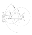
3組のリンク機構34は、幾何学的に同一形状をなす。幾何学的に同一形状とは、図7に示すように、各リンク部材35,36,37を直線で表現した幾何学モデル、すなわち各回転対偶と、これら回転対偶間を結ぶ直線とで表現したモデルが、中央リンク部材37の中央部に対する基端側部分と先端側部分が対称を成す形状であることをいう。図7は、一組のリンク機構34を直線で表現した図である。この実施形態のパラレルリンク機構5は回転対称タイプで、基端側のリンクハブ32および基端側の端部リンク部材35からなる基端側部分と、先端側のリンクハブ33および先端側の端部リンク部材36からなる先端側部分との位置関係が、中央リンク部材37の中心線Cに対して回転対称となる位置構成になっている。
基端側のリンクハブ32と先端側のリンクハブ33と3組のリンク機構34とで、基端側のリンクハブ32に対し先端側のリンクハブ33が直交2軸回りに回転自在な2自由度機構が構成されている。言い換えると、基端側のリンクハブ32に対して先端側のリンクハブ33を、回転が2自由度で姿勢変更自在な機構である。この2自由度機構は、コンパクトでありながら、基端側のリンクハブ32に対する先端側のリンクハブ33の可動範囲を広くとれる。
例えば、基端側の球面リンク中心PAを通り、基端側のリンクハブ32と基端側の端部リンク部材35の各回転対偶の中心軸O1(図6)と直角に交わる直線を基端側のリンクハブ32の中心軸QAとする。同様に、先端側の球面リンク中心PBを通り、先端側のリンクハブ33と先端側の端部リンク部材36の各回転対偶の中心軸O1(図6)と直角に交わる直線を先端側のリンクハブ33の中心軸QBとする。
この場合、基端側のリンクハブ32の中心軸QAと先端側のリンクハブ33の中心軸QBとの折れ角θ(図7)の最大値を約±90°とすることができる。また、基端側のリンクハブ32に対する先端側のリンクハブ33の旋回角φ(図7)を0°~360°の範囲に設定できる。折れ角θは、基端側のリンクハブ32の中心軸QAに対して先端側のリンクハブ33の中心軸QBが傾斜した垂直角度のことである。旋回角φは、基端側のリンクハブ32の中心軸QAに対して先端側のリンクハブ33の中心軸QBが傾斜した水平角度のことである。
基端側のリンクハブ32に対する先端側のリンクハブ33の姿勢変更は、基端側のリンクハブ32の中心軸QAと先端側のリンクハブ33の中心軸QBとの交点Oを回転中心として行われる。図4は、基端側のリンクハブ32の中心軸QAと先端側のリンクハブ33の中心軸QBが同一線上にある状態を示し、図5は、基端側のリンクハブ32の中心軸QAに対して先端側のリンクハブ33の中心軸QBが或る作動角をとった状態を示す。姿勢が変化しても、基端側と先端側の球面リンク中心PA,PB間の距離L(図7)は変化しない。
各リンク機構34が以下の各条件を満たす場合、幾何学的対称性から基端側のリンクハブ32および基端側の端部リンク部材35と、基端側のリンクハブ33および先端側の端部リンク部材36とは同じに動く。よって、パラレルリンク機構5は、基端側から先端側へ回転伝達を行う場合、基端側と先端側は同じ回転角になって等速で回転する等速自在継手として機能する。
条件1:基端側および先端側において、各リンク機構34におけるリンクハブ32,33と端部リンク部材35,36との回転対偶の中心軸O1の角度および長さが互いに等しい。
条件2:基端側および先端側において、リンクハブ32,33と端部リンク部材35,36との回転対偶の中心軸O1および端部リンク部材35,36と中央リンク部材37との回転対偶の中心軸O2が、それぞれの球面リンク中心PA,PBで交差する。
条件2:基端側および先端側において、リンクハブ32,33と端部リンク部材35,36との回転対偶の中心軸O1および端部リンク部材35,36と中央リンク部材37との回転対偶の中心軸O2が、それぞれの球面リンク中心PA,PBで交差する。
条件3:基端側の端部リンク部材35と先端側の端部リンク部材36の幾何学的形状が等しい。
条件4:中央リンク部材37における基端側部分と先端側部分の幾何学的形状が等しい。
条件5:中央リンク部材37の対称面に対して、中央リンク部材37と端部リンク部材35,36との角度位置関係が基端側と先端側とで同じである。
条件4:中央リンク部材37における基端側部分と先端側部分の幾何学的形状が等しい。
条件5:中央リンク部材37の対称面に対して、中央リンク部材37と端部リンク部材35,36との角度位置関係が基端側と先端側とで同じである。
図3~図5に示すように、基端側のリンクハブ32は、基端部材40と、この基端部材40と一体に設けられた3個の回転軸連結部材41とを有している。基端部材40は、中央部に円形の貫通孔40a(図3)を有し、この貫通孔40aの周囲に3個の回転軸連結部材41が円周方向に等間隔で配置されている。貫通孔40aの中心は、基端側のリンクハブ32の中心軸QA上に位置する。各回転軸連結部材41に、軸心が基端側のリンクハブ32の中心軸QAと交差する回転軸42(図4、図5)が回転自在に連結されている。この回転軸42に、基端側の端部リンク部材35の一端が連結されている。
図6に示すように、回転軸42は、2個の軸受43を介して回転軸連結部材41に回転自在に支持されている。軸受43は、例えば、深溝玉軸受、アンギュラ玉軸受等の玉軸受である。これらの軸受43は、回転軸連結部材41に設けられた内径孔44に嵌合状態で設置され、圧入、接着、加締め等の方法で固定されている。他の回転対偶部に設けられる軸受の種類および設置方法も同様である。
回転軸42に、この回転軸42と一体に回転するように、基端側の端部リンク部材35の一端と、後述の軸直交型減速機77の一構成要素である扇形のかさ歯車45とが結合されている。詳しくは、基端側の端部リンク部材35の一端に切欠き部46が形成されており、この切欠き部46の両側部分である内外の回転軸支持部47,48間に回転軸連結部材41が配置されている。かさ歯車45は、内側の回転軸支持部47の内側面に当接して配置されている。
回転軸42が内側から、かさ歯車45に形成された貫通孔、内側の回転軸支持部47に形成された貫通孔、軸受43の内輪、外側の回転軸支持部48に形成された貫通孔の順に挿通され、回転軸42のねじ部42bがナット50に螺合されている。回転軸42の頭部42aとナット50とで、かさ歯車45、内外の回転軸支持部47,48および軸受43の内輪を挟持してこれらを互いに結合する。内外の回転軸支持部47,48と軸受43との間にスペーサ51,52が介在されており、ナット50の螺着時に軸受43に予圧が付与されている。
基端側の端部リンク部材35の他端に、回転軸55が結合されている。回転軸55は、2個の軸受53を介して中央リンク部材37の一端に回転自在に連結されている。詳しくは、基端側の端部リンク部材35の他端に切欠き部56が形成されており、この切欠き部56の両側部分である内外の回転軸支持部57,58間に中央リンク部材37の一端が配置されている。
回転軸55が外側から、外側の回転軸支持部58に形成された貫通孔、軸受53の内輪、内側の回転軸支持部57に形成された貫通孔の順に挿通され、回転軸55のねじ部55bがナット60に螺合されている。回転軸55の頭部55aとナット60とで、内外の回転軸支持部57,58および軸受53の内輪が挟持されてこれらを互いに結合する。内外の回転軸支持部57,58と軸受53との間にスペーサ61,62が介在されており、ナット60の螺着時に軸受53に予圧が付与されている。
図4、図5に示すように、先端側のリンクハブ33は、先端部材70と、この先端部材70の内面に円周方向等配で設けられた3個の回転軸連結部材71とを有している。各回転軸連結部材71が配置される円周の中心は、先端側のリンクハブ33の中心軸QB上に位置する。各回転軸連結部材71に、軸心が先端側のリンクハブ33の中心軸QBと交差する回転軸73が回転自在に連結されている。この先端側のリンクハブ33の回転軸73に、先端側の端部リンク部材36の一端が連結されている。
先端側の端部リンク部材36の他端に、中央リンク部材37の他端に回転自在に連結された回転軸75が連結されている。先端側のリンクハブ33の回転軸73および中央リンク部材37の回転軸75は、上述の回転軸42,55と同様に、2個の軸受(図示せず)を介して回転軸連結部材71および中央リンク部材37の他端にそれぞれ回転自在に連結されている。
図3に示すように、パラレルリンク機構5を作動させる姿勢制御用アクチュエータ31は、基端部材40に設置されている。姿勢制御用アクチュエータ31の出力軸31aは、基端側のリンクハブ32の中心軸QAと平行である。姿勢制御用アクチュエータ31の数は、リンク機構34と同数の3個である。なお、この例では、リンク機構34と同数の姿勢制御用アクチュエータ31が設けられているが、3組のリンク機構34のうち少なくとも2組に姿勢制御用アクチュエータ31が設けられていれば、基端側のリンクハブ32に対する先端側のリンクハブ33の姿勢を確定することができる。
姿勢制御用アクチュエータ31の出力軸31aに取り付けられたかさ歯車76と基端側のリンクハブ32の回転軸42に取り付けられた扇形のかさ歯車45とが噛み合っている。これら一対のかさ歯車76,45により、入力側軸と出力側軸とが互いに直交した軸直交型減速機77が構成されている。図6に示すように、姿勢制御用アクチュエータ31および軸直交型減速機77は、基端側のリンクハブ32と基端側の端部リンク部材35との回転対偶部よりも内径側に配置されている。
各姿勢制御用アクチュエータ31を回転駆動することで、パラレルリンク機構5が作動する。詳しくは、姿勢制御用アクチュエータ31を回転駆動すると、その回転が一対のかさ歯車76,45からなる軸直交型減速機77を介して回転軸42に伝達され、基端側のリンクハブ32に対する基端側の端部リンク部材35の角度が変更する。それにより、基端側のリンクハブ32に対する先端側のリンクハブ33の姿勢が決まる。ここでは、軸直交型減速機77が一対のかさ歯車76,45からなるが、その他に、ウォームギヤとピニオンギヤを用いた機構、ハイポイドギヤ(商標名)を用いた機構等であってもよい。
<エンドエフェクタ作動機構用アクチュエータ>
パラレルリンク機構回転用アクチュエータ13および姿勢制御用アクチュエータ31として使用されるエンドエフェクタ作動機構用アクチュエータについて、図8A,図8B,図8Cおよび図9と共に詳しく説明する。
パラレルリンク機構回転用アクチュエータ13および姿勢制御用アクチュエータ31として使用されるエンドエフェクタ作動機構用アクチュエータについて、図8A,図8B,図8Cおよび図9と共に詳しく説明する。
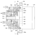
図8Aに示すように、エンドエフェクタ作動機構用アクチュエータは、回転駆動部である駆動モータ150を有し、この駆動モータ150のモータ軸151に、キー152により筒状の入力軸153が連結されている。入力軸153の先端に、軸受154を介して出力軸155が回転自在に支持されている。出力軸155は、円板状の端面部材155aと、その背面に固定された背面側部材155bとを有している。出力軸155の背面側部材155bは、クロスローラ軸受156の内輪に結合されている。クロスローラ軸受156は、駆動モータ150のハウジングに外輪を固定して設けられている。
入力軸153から出力軸155への動力伝達経路には、クラッチ機構230および減速機構160が設けられている。
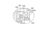
クラッチ機構230は、ブレーキ板231と、ブレーキ板231の外側面と軸方向で対向するアーマチェア232と、ブレーキ板231の内側面と軸方向で対向する摩擦板233と、アーマチェア232をブレーキ板231に押し付ける複数のブレーキばね234と、コイル235aに通電することでアーマチェア232をブレーキばね234の弾力に抗してブレーキ板231から離反させる電磁石235とを備えた無励磁型電磁ブレーキである。
ブレーキ板231は、連結部材164の外周に回転不能に嵌め込まれている。連結部材164は、軸受165を介して入力軸151に回転自在に支持されている。摩擦板233と電磁石235とは、両者間に介在するスペーサ236によって所定の間隔が開けられている。
電磁石235のコイル235aに通電されていないときには、図8Bのように、ブレーキばね234がアーマチェア232をブレーキ板231に押し付けることにより、アーマチェア232に押されたブレーキ板231が摩擦板233に押し付けられる。電磁石235のコイル235aに通電すると、図8Cのように、電磁石235がアーマチェア232を吸引してブレーキばね234の弾力に抗して軸方向に移動させ、ブレーキ板231から離反させる。
上記構成であるクラッチ機構230は、コイル235aに非通電であるときは、ブレーキ板231とこれに連結された連結部材164をロックして、回転不能に拘束する。すなわち、クラッチ接続状態となる。コイル235aに通電すると、ブレーキ板231および連結部材164のロックを解除して、回転自在にする。すなわち、クラッチ遮断状態となる。
減速機構160は、楕円と真円の差動を利用した波動歯車機構からなる。具体的には、減速機構160は、入力軸151と回転伝達可能に連結されるウェイブジェネレータ(波動発生器)161と、このウェイブジェネレータ161の径方向外側に配されるサーキュラースプライン(剛性内歯歯車)162と、これらウェイブジェネレータ161およびサーキュラースプライン162の間に円筒部が挟まれるフレックススプライン(可撓性外歯歯車)163とからなる。
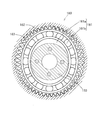
図9に示すように、ウェイブジェネレータ161は、径方向断面が楕円形のカム161aの外周にボールベアリング161bの内輪を嵌合固定したもので、入力軸151の大径部に回転伝達可能に連結されている。
サーキュラースプライン162は、内周に歯が設けられた円環状の部品であり、図8Aに示すように、連結部材164に結合されている。前述のように、連結部材164はブレーキ板231に対して回転不能であるため、サーキュラースプライン162は、連結部材164を介してブレーキ板231に相対回転不能に連結されている。
フレックススプライン163は、金属弾性体で形成され、円筒部の外周にサーキュラースプライン162の内周の歯と噛み合う歯が設けられた薄肉カップ状の部品である。フレックススプライン163は、その蓋部で出力軸153の背面側部材155bに固定されている。
クラッチ機構230および減速機構160は、以下のように動作する。
クラッチ機構230のコイル235aに通電されておらずクラッチ接続状態のとき、すなわち減速機構160のサーキュラースプライン162が回転不能に拘束された状態のときに駆動モータ150から入力軸151に入力トルクが加えられると、まず、入力軸151と一体にウェイブジェネレータ161のボールベアリング161bの内輪が回転する。すると、ボールベアリング161bの外輪に円筒部の内周を押圧されたフレックススプライン1631が、弾性変形してサーキュラースプライン162との噛合位置を変えていく。これにより、フレックススプライン163がサーキュラースプライン162との歯数の差分だけ回転し、その回転が出力軸153に伝達される。
クラッチ機構230のコイル235aに通電されておらずクラッチ接続状態のとき、すなわち減速機構160のサーキュラースプライン162が回転不能に拘束された状態のときに駆動モータ150から入力軸151に入力トルクが加えられると、まず、入力軸151と一体にウェイブジェネレータ161のボールベアリング161bの内輪が回転する。すると、ボールベアリング161bの外輪に円筒部の内周を押圧されたフレックススプライン1631が、弾性変形してサーキュラースプライン162との噛合位置を変えていく。これにより、フレックススプライン163がサーキュラースプライン162との歯数の差分だけ回転し、その回転が出力軸153に伝達される。
一方、クラッチ機構230のコイル235aに通電されたクラッチ遮断状態のとき、すなわち減速機構160のサーキュラースプライン162が回転自在に解放された状態のときに外部から出力軸153に逆入力トルクが加えられると、まず、出力軸153と一体にフレックススプライン163が回転する。すると、サーキュラースプライン162はフレックススプライン163と一体に(フレックススプライン163との噛合位置を変えることなく)回転する。
このとき、フレックススプライン163とその内周に嵌め込まれたウェイブジェネレータ161のボールベアリング161bの外輪は、停止しているボールベアリング161bの内輪の外形に沿うように弾性変形しながら回転するので、入力軸151には回転が伝達されない。サーキュラースプライン162を回転自在に解放すれば、逆入力トルクに対しては、入力軸151を増速させる動作を行わなくなって、サーキュラースプライン162を回転不能に拘束している場合に比べて回転トルクが大幅に低減されるので、出力側から出力軸153を容易に回転させることができる。
したがって、通常運転時(電磁石235のコイル235aに非通電の状態)は減速機構160によって高い減速率が得られる。また、駆動モータ150を停止中、電磁石235のコイル235aに通電すると、出力軸153に逆入力トルクが加えられた場合、その逆入力トルクの大きさに応じて、エンドエフェクタ動作機構であるパラレルリンク機構5が動作する。すなわち、パラレルリンク機構回転用アクチュエータ13がクラッチ遮断状態となることでパラレルリンク機構5が軸心C3回りに回転自在となり、また姿勢制御用アクチュエータ31がクラッチ遮断状態となることで先端側のリンクハブ33が自由に姿勢変更可能となる。
駆動モータ150の外側面に、駆動モータ150の回転速度を検出する入力側エンコーダ170が取り付けられている。また、出力軸155の背面側部材155bの外周に嵌合固定されたエンコーダディスク171aと、クロスローラ軸受156の外輪の外側面に固定された検出部171bとで、出力側エンコーダ(アブソリュートエンコーダ)171を構成している。
このように入力側エンコーダ170および出力側エンコーダ171を設けることにより、出力側から出力軸155を回転させた後も、出力軸155の回転方向位置を正確に検出することができる。それにより、つぎに駆動モータ150を回転駆動するときに、出力軸155を精度良く位置決めすることが可能である。
エンドエフェクタ動作用アクチュエータはフランジ部158の貫通孔158aに挿通したボルトにより、外部部材に固定されている。パラレルリンク機構回転用アクチュエータ13の場合、外部部材が第二アーム4(図1)であり、出力軸155の端面部材155aにパラレルリンク機構5の基端部材40(図3)が固定される。また、姿勢制御用アクチュエータ31の場合、外部部材が基端部材40であり、出力軸155の端面部材155aにかさ歯車76(図3)が取り付けられる。この場合、出力軸155が、姿勢制御用アクチュエータ31の出力軸31aである。
<1軸直動機構>
図1において、1軸直動機構6は、パラレルリンク機構5の先端側のリンクハブ33に、直動方向が先端側のリンクハブ33の中心軸QBと一致するように取り付けられている。1軸直動機構6として、例えばすべりねじ構造のものが使用される。
図1において、1軸直動機構6は、パラレルリンク機構5の先端側のリンクハブ33に、直動方向が先端側のリンクハブ33の中心軸QBと一致するように取り付けられている。1軸直動機構6として、例えばすべりねじ構造のものが使用される。
図10~図12にすべりねじ構造からなる1軸直動機構の一例を示す。図10は1軸直動機構の断面図、図11は図10のXI-XI断面図、図12は同1軸直動機構の右側面図である。なお、図10は図11のX-O4-X断面を示している。
この1軸直動機構6は、中空モータ101の回転を直線運動に変換して、スライド軸102を軸方向に進退させる。1軸直動機構6は、中空モータ101、ナット103、スライド軸102、一対の係止体104,105および回転検出手段106を備える。
中空モータ101は、固定子110と、コイル111と、永久磁石112と、回転子である中空軸113とを有している。コイル111への通電は、図示しない制御装置により制御される。
固定子110は、この1軸直動機構6のハウジングを構成し、軸方向中央部の固定子本体114と、この固定子本体114の一方の端面に固定されたフランジ形成部材115と、固定子本体114およびフランジ形成部材115の端面にそれぞれ固定された一対の蓋116,117とを有している。フランジ形成部材115および蓋116は固定ボルト118によって固定子本体114に固定され、蓋117は固定ボルト119によって固定子本体114に固定されている。
フランジ形成部材115は外周にフランジ部115aを有し、このフランジ部115aに、1軸直動機構6を他の機器に取り付けるための貫通孔120が設けられている。また、蓋116,117の内周部は、スライド軸102を回転および軸方向移動自在に支持するラジアル軸受部121,122を構成している。これらラジアル軸受部121,122は、樹脂で形成されている。
中空モータ101は、固定子本体114の内周にコイル111が配置され、このコイル111の内周に対向して永久磁石112が配置されている。永久磁石112は、中空軸113の外周面に固定されている。中空軸113の両端部は、フランジ形成部材115および固定子本体114にそれぞれ設置された一対の転がり軸受123,124によって回転自在に支持されている。
ナット103は、中空軸113の内径部に固定されている。ナット103の軸方向一端側(図10の左側)には雌ねじ125が形成され、軸方向他端側(図10の右側)は、スライド軸102を回転および軸方向移動自在に支持するラジアル軸受部126とされている。例えば、ナット103は樹脂製であり、インサート成形により金属製の中空軸113と一体化されている。ナット103の外周面に設けられた凸部103aが中空軸113の内周面に食い込んだ形状とされており、ナット103と中空軸113とが強固に一体化されている。
ナット103、および蓋116,117のラジアル軸受部121,122に用いる樹脂としては、スライド軸102との優れた摺動性を有し、かつスライド軸102を構成する金属よりも硬度が低いことが求められる。このような要求を満たす樹脂材としては、例えば、フッ素系樹脂組成物や超高分子量ポリエチレン樹脂組成物等が挙げられる。
フッ素系樹脂組成物は、フッ素系樹脂を主成分とする。フッ素系樹脂としては、ポリテトラルオロエチレン樹脂(略称PTFE)、テトラフルオロエチレン‐ヘキサフルオロプロピレン共重合体樹脂(略称FEP)、テトラフルオロエチレン‐パーフルオロアルキルビニルエーテル共重合体樹脂(略称PFE)、エチレン‐テトラフルオロエチレン共重合体樹脂、ポリクロロトリフルエチレン樹脂、エチレン‐クロロフルオロエチレン共重合体樹脂等が挙げられる。これらは、それぞれ単独もしくは、上記フッ素系樹脂のモノマーの例えば1:10から10:1の重合割合で、2種以上の共重合体や3元共重合体等からなる樹脂であってもよい。
スライド軸102は、ハウジングをなす固定子110よりも軸方向に長い軸であって、外周の軸方向両端間にわたって雄ねじ127が形成されている。この雄ねじ127は、ナット103の雌ねじ125に螺合している。
また、スライド軸102の外周には、軸方向両端間に軸方向に延びる回り止め溝128が形成されている。つまり、雄ねじ127と回り止め溝128は軸方向の同じ箇所に形成されており、雄ねじ127の周方向の一部分が回り止め溝128によって切り欠かれた状態となっている。図の例では、回り止め溝128の数が一つであるが、円周方向に分散して複数あってもよい。
係止体104,105は、それぞれ固定ボルト130,130により蓋116,117に固定され、その先端がスライド軸102の回り止め溝128内に挿入されている。これにより、スライド軸102が回り止めされている。回り止め溝128と係止体104,105とで、回り止め機構を構成する。回り止め機構は、他の構成であってもよい。例えば、回り止め溝128内をボールが転動する構成としてもよい。
回転検出手段106は、中空軸113に設けられた磁気エンコーダ131と、固定子本体114に設けられた磁気センサ132とを有し、これら磁気エンコーダ131および磁気センサ132が互いに軸方向に対向している。磁気センサ132は、制御装置に接続されている。
上記構成の1軸直動機構6は、以下のように動作する。
制御装置(図示せず)の制御により、コイル111が通電されると、中空モータ101の中空軸113が回転し、この中空軸113に設けられたナット103が回転する。このナット103に螺合したスライド軸102も回転しようとするが、スライド軸102は、回り止め溝128に係合した係止体104,105により回り止めされているので回転できずに、軸方向に進退する。中空軸113の回転は回転検出手段106に検出され、その検出信号が制御装置に送られる。
制御装置(図示せず)の制御により、コイル111が通電されると、中空モータ101の中空軸113が回転し、この中空軸113に設けられたナット103が回転する。このナット103に螺合したスライド軸102も回転しようとするが、スライド軸102は、回り止め溝128に係合した係止体104,105により回り止めされているので回転できずに、軸方向に進退する。中空軸113の回転は回転検出手段106に検出され、その検出信号が制御装置に送られる。
スライド軸102の雄ねじ127と回り止め溝128とが軸方向の同じ箇所に形成されているので、スライド軸102の軸方向長さを長くすることなく、十分な長さのストロークを得ることができる。また、固定子110の蓋116,117およびナット103にラジアル軸受部121,122,126が設けられているので、スライド軸102を支持するための軸受を別途に設ける必要がなく、その分だけ1軸直動機構6を軸方向にコンパクトに構成できる。
ナット103のラジアル軸受部126だけでも、スライド軸102を回転および軸方向移動自在に支持することができるが、固定子110にもラジアル軸受部121,122を設けることで、スライド軸102の支持が安定する。追加のラジアル軸受部121,122を固定子110に設けることにより、1軸直動機構6の軸方向長さを変えることなく、スライド軸102の支持の安定化を図れる。
ナット103が樹脂製であるので、スライド軸102に対する摺動性が良い。具体的には、ナット103の雌ねじ125とスライド軸102の雄ねじ127との摺動性が良く、かつナット103のラジアル軸受部126とスライド軸102の外周面(雄ねじ127のねじ山)との摺動性が良い。同様に、蓋116,117のラジアル軸受部121,122も樹脂製であるので、これらラジアル軸受部121,122とスライド軸102の外周面との摺動性も良い。このため、上記各摺動部に潤滑材を供給しなくてもよく、1軸直動機構6の全体構成を簡略にすることができる。
さらに、スライド軸102の回り止めをする二つの係止体104,105が、固定子における110における軸方向両端にそれぞれ設けられている。このように、軸方向に離れた複数の係止体104,105でスライド軸102の回り止めをすることにより、ナット103の回転方向が反転するときなどにガタが生じ難く、安定した動作を行うことができる。
スライド軸102の一端に、エンドエフェクタ取付部材140が設けられている。エンドエフェクタ取付部材140は、エンドエフェクタ取付用のねじ孔141を有し、固定ボルト142によってスライド軸102に固定されている。また、スライド軸102の他端には、抜け止め用部材142が固定ボルト143によって固定されている。
この1軸直動機構6は、フランジ部115aの貫通孔120に挿通したボルトによって、パラレルリンク機構5の先端部材70に固定されている。そして、エンドエフェクタ取付部材140に、作業内容に応じたエンドエフェクタが取り付けられている。
<操作方法>
以下に、この多関節ロボット1の操作方法を、エンドエフェクタに把持された物品を固定位置に設けられたワークの穴に挿入する場合を例にとって説明する。図13A,図13Bは、エンドエフェクタ取付部材140に物品把持用のエンドエフェクタ300を取り付け、このエンドエフェクタ300で円柱状の物品301を把持し、その物品301を斜め姿勢で設置されたワーク302の円筒状の穴302aに挿入する作業を示している。穴302aの内径は、物品301の外径よりも少しだけ大きい。
以下に、この多関節ロボット1の操作方法を、エンドエフェクタに把持された物品を固定位置に設けられたワークの穴に挿入する場合を例にとって説明する。図13A,図13Bは、エンドエフェクタ取付部材140に物品把持用のエンドエフェクタ300を取り付け、このエンドエフェクタ300で円柱状の物品301を把持し、その物品301を斜め姿勢で設置されたワーク302の円筒状の穴302aに挿入する作業を示している。穴302aの内径は、物品301の外径よりも少しだけ大きい。
この場合の多関節ロボット1の操作方法としては、まず、図13Aのように、第一アーム3および第二アーム4を回転させてエンドエフェクタ300の平面視位置を決めるとともに、パラレルリンク機構5を作動させてエンドエフェクタ300の姿勢を決める。エンドエフェクタ300の姿勢は、軸心C3回りの回転位置と、先端側のリンクハブ33の姿勢とによって決められる。具体的には、物品301の先端をワーク302の穴302aの出口付近に位置させ、かつ多関節ロボット1の制御上で計算によって求められる物品301の中心軸を実際の穴302aの中心軸に一致させる。パラレルリンク機構5によりエンドエフェクタ300の姿勢を決めるとき、パラレルリンク機構回転用アクチュエータ13および姿勢制御用アクチュエータ31はクラッチ接続状態になっている。
エンドエフェクタ300の位置および姿勢が決まると、図13Bのように、1軸直動機構6によりエンドエフェクタ300を移動させ、物品301をワーク302の穴302aに挿入する。その際、パラレルリンク機構回転用アクチュエータ13および姿勢制御用アクチュエータ31をクラッチ遮断状態にして、これらアクチュエータ13,31の駆動モータ150へ逆入力トルクが伝達されないようにする。これにより、パラレルリンク機構5が、外力に応じて自由に動けるようなる。このため、1軸直動機構6の構造上の問題で、物品301の中心軸D1が穴302aの中心軸D2に対して少しずれていたとしても、穴302aの内壁から受ける力に応じてパラレルリンク機構5が動くことにより前記ずれを吸収して、物品301をワーク302の穴302aに挿入することができる。
このように、この多関節ロボット1は、パラレルリンク機構5によりエンドエフェクタ300の姿勢を決めた状態で、1軸直動機構6によりエンドエフェクタ300を1軸方向に進退させる。このため、エンドエフェクタ300が把持した物品301を固定位置に設けられたワーク302の穴302aに挿入するという難しい作業を、1軸直動機構6を作動させるだけで行うことでき、制御が容易である。
また、1軸直動機構6による送り方向の少しのずれを許容することができる。このため、1軸直動機構6として、この実施形態のように、構造的に送り方向のずれが生じる可能性があるすべりねじ機構を使用することができる。すべりねじ機構は、比較的に軽量かつ簡素な構造であり、低コストで製作することができる。
[第1の実施形態の変形例1]
図14は、第1の実施形態に対して、第一アーム3を昇降させる昇降機構8が設けられた多関節ロボット1を示す。昇降機構8は、天井面に支持体180を固定し、この支持体180に直動アクチュエータ181をその進退方向が鉛直方向となるように設け、この直動アクチュエータ181に昇降部材182が固定されている。昇降部材182に、第一アーム3が鉛直方向の軸心C1回りに回転自在に支持されている。第一アーム回転用アクチュエータ11は、昇降部材182の内部に設けられている。
図14は、第1の実施形態に対して、第一アーム3を昇降させる昇降機構8が設けられた多関節ロボット1を示す。昇降機構8は、天井面に支持体180を固定し、この支持体180に直動アクチュエータ181をその進退方向が鉛直方向となるように設け、この直動アクチュエータ181に昇降部材182が固定されている。昇降部材182に、第一アーム3が鉛直方向の軸心C1回りに回転自在に支持されている。第一アーム回転用アクチュエータ11は、昇降部材182の内部に設けられている。
昇降機構8は、カバー183によって覆われている。カバー183は、天井面に固定された固定部183aと、昇降部材182に取り付けられ固定部材183に対して上下に摺動する昇降部183bとを有している。
このように昇降機構8を設けると、エンドエフェクタの上下位置を任意に変えることができるので、多関節ロボット1の作業用途が広がる。その他の構成は、第1の実施形態と同じである。
[第1の実施形態の変形例2]
図15は、第1の実施形態とはリンク作動装置30の構成が異なる多関節ロボット1を示す。以下、第1の実施形態と構成が異なる箇所についてのみ説明し、構成が同じ箇所については、図面に第1実施形態と同一符号を付して表し、その説明を省略する。
図15は、第1の実施形態とはリンク作動装置30の構成が異なる多関節ロボット1を示す。以下、第1の実施形態と構成が異なる箇所についてのみ説明し、構成が同じ箇所については、図面に第1実施形態と同一符号を付して表し、その説明を省略する。
図16はパラレルリンク機構と姿勢制御用アクチュエータの一部を省略して示す正面図である。この変形例2のリンク作動装置30も、第1の実施形態と同様に、パラレルリンク機構5と姿勢制御用アクチュエータ31とを有している。また、パラレルリンク機構5は、基端側のリンクハブ32に対し先端側のリンクハブ33が3組のリンク機構34を介して姿勢変更可能に連結されている。この変形例2のリンク作動装置30が第1の実施形態と異なる点は、後述するように、各姿勢制御用アクチュエータ31が、その出力軸31aを基端側のリンクハブ32と基端側の端部リンク部材35の回転対偶部の回転軸22と軸心を一致させて配置されていることである。
図17Aは図16のXVII-PA-XVII断面図で、図17Bはその部分拡大図である。基端側のリンクハブ32の各回転軸連結部材21に回転軸22が回転自在に支持され、この回転軸22に基端側の端部リンク部材35の一端が連結されている。この変形例2の回転軸22は、大径部22a、小径部22bおよび雄ねじ部22cを有し、小径部22bで2個の軸受23を介して回転軸連結部材21に回転自在に支持されている。軸受23は、例えば深溝玉軸受、アンギュラ玉軸受等の玉軸受である。これらの軸受23は、回転軸連結部21に設けられた内径溝24に嵌合状態で設置され、圧入、接着、加締め等の方法で固定されている。他の回転対偶部に設けられる軸受の種類および設置方法も同様である。
回転軸22は、大径部22aで姿勢制御用アクチュエータ31の出力軸31aに同軸上に配置されている。その配置構造は後述する。また、回転軸22に、この回転軸22と一体に回転するように、基端側の端部リンク部材35の一端が連結されている。すなわち、基端側の端部リンク部材35の一端に形成された切欠き部25内に回転軸連結部材21が配置され、回転軸22の小径部22bが、切欠き部25の両側部分である内外一対の回転軸支持部26,27にそれぞれ形成された貫通孔および軸受23の内輪に挿通されている。
回転軸22の大径部22aの外周に嵌合するスペーサ28を介し、基端側の端部リンク部材35と姿勢制御用アクチュエータ31の出力軸31aとがボルト29で固定されると共に、外側の回転軸支持部27よりも突出した回転軸22の雄ねじ部22cにナット80が螺着されている。軸受23の内輪と一対の回転軸支持部26,27との間に、スペーサ81,82が介在されており、ナット80を螺着時に軸受23に予圧が付与されている。
姿勢制御用アクチュエータ31は、回転軸22と同軸上に設置され、モータ固定部材83により基端側のリンクハブ32の基端部材20の上面に固定されている。この姿勢制御用アクチュエータ31も、第1の実施形態と同様に、図8Aに示す構成のエンドエフェクタ動作機構用アクチュエータである。
図17Bにおいて、出力軸31aの先端面は、出力軸31aの中心線と直交する平面状のフランジ面84である。出力軸31aは、スペーサ28を介して、基端側の端部リンク部材35の回転軸支持部26にボルト29で接続されている。回転軸22の大径部22aが、基端側のリンクハブ32と基端側の端部リンク部材35の回転対偶部を構成し、この大径部22aが、出力軸31aに設けられた内径溝87に嵌っている。
この変形例2のリンク作動装置30を用いた場合も、第1の実施形態のリンク作動装置30を用いた場合と同様の作用・効果が得られる。また、エンドエフェクタ作動機構としては、エンドエフェクタの姿勢を変更することが可能であれば、パラレルリンク機構5以外の回転2自由度機構を採用してもよい。
[第2の実施形態]
図18Aおよび図18Bはそれぞれ、第2の実施形態にかかる多関節ロボットの平面図および正面図である。この多関節ロボット201は、地面に固定の支持体202に設けられた昇降機構208と、この昇降機構208に支持され鉛直方向の軸心C1回りに回転自在に支持された第一アーム203と、この第一アーム203の先端に鉛直方向の軸心C2回りに回転自在に支持された第二アーム204と、この第二アーム204の先端に設けられ鉛直方向の軸心C3回りにエンドエフェクタを回転させるエンドエフェクタ作動機構としてのエンドエフェクタ回転機構205とを備える。エンドエフェクタ回転機構205から下方に延びる回転軸の先端に、物品把持用のエンドエフェクタ300が取り付けられている。
図18Aおよび図18Bはそれぞれ、第2の実施形態にかかる多関節ロボットの平面図および正面図である。この多関節ロボット201は、地面に固定の支持体202に設けられた昇降機構208と、この昇降機構208に支持され鉛直方向の軸心C1回りに回転自在に支持された第一アーム203と、この第一アーム203の先端に鉛直方向の軸心C2回りに回転自在に支持された第二アーム204と、この第二アーム204の先端に設けられ鉛直方向の軸心C3回りにエンドエフェクタを回転させるエンドエフェクタ作動機構としてのエンドエフェクタ回転機構205とを備える。エンドエフェクタ回転機構205から下方に延びる回転軸の先端に、物品把持用のエンドエフェクタ300が取り付けられている。
第一アーム203は、支持体202の内部に設置された第一アーム用アクチュエータ211により軸心C1回りに回転させられる。第二アーム204は、第一アーム203の先端上面部に設置された第二アーム用アクチュエータ212により軸心C2回りに回転させられる。これら第一アーム用アクチュエータ211および第二アーム用アクチュエータ212は、第1の実施形態におけるエンドエフェクタ作動機構用アクチュエータと同様に、図8A、図8B、図9に示す構成のものであり、出力側に加えられた逆入力トルクの回転駆動部への伝達を遮断可能なクラッチ機構を具備する。
エンドエフェクタ回転機構205の下方には、ワーク302を水平面に沿って一定方向に移動させるワーク搬送装置220が設けられている。ワーク搬送装置220は、例えば、ベルトコンベア装置である。ワーク搬送装置220には、所定の間隔でワーク載せ台221が設けられ、このワーク載せ台221に載せられたワーク302が搬送される。ワーク302は、複数本の位置決めピン222によりワーク載せ台221の上に位置決めされている。
<操作方法>
この多関節ロボット1の操作方法を、図19A、図19B、図20Aおよび図20Bに示すように、エンドエフェクタ300に把持された物品301をワーク搬送装置220で搬送されるワーク302の上向きの穴302aに挿入する場合を例にとって説明する。物品301は円柱状で、ワーク302の穴302aは、内径が物品301の外径よりも少しだけ大きい円筒状である。
この多関節ロボット1の操作方法を、図19A、図19B、図20Aおよび図20Bに示すように、エンドエフェクタ300に把持された物品301をワーク搬送装置220で搬送されるワーク302の上向きの穴302aに挿入する場合を例にとって説明する。物品301は円柱状で、ワーク302の穴302aは、内径が物品301の外径よりも少しだけ大きい円筒状である。
作業時には、第一アーム203および第二アーム204を回転作動させて、エンドエフェクタ300を所定の作業位置の上方で待機させる。その際、エンドエフェクタ300に把持されたが物品301の中心軸が、所定の作業位置Pにあるワーク302の穴302aの中心軸と一致するように位置決めする。第一アーム203および第二アーム204によりエンドエフェクタ300の平面視位置を決めるとき、第一アーム回転用アクチュエータ211および第二アーム回転用アクチュエータ212はクラッチ接続状態になっている。
その後、図19A、図19Bのように、ワーク302が作業位置まで搬送されてくると、そこで搬送を停止する。つづいて、第一アーム用アクチュエータ211および第二アーム用アクチュエータ212をクラッチ遮断状態してから、昇降機構208を作動させて、第一アーム203および第二アーム204ごとエンドエフェクタ300を下降させ、物品301をワーク302の穴302aに挿入する。
前述したように、物品301の中心軸がワーク302の穴302aの中心軸と一致するように位置決めされているが、実際には、図19A、図19Bに図示されているように、ワーク搬送装置220の振動等により物品301とワーク302の穴302aの位置がずれる場合がある。しかしながら、第一アーム用アクチュエータ211および第二アーム用アクチュエータ212がクラッチ遮断状態であり、第一アーム203および第二アーム204が自由に動ける。このため、物品301の中心軸と穴302aの中心軸とが少しずれていたとしても、図20A、図20Bのように、穴302aの内壁からの受ける力に応じて第一アーム211および第二アーム212が動く。これにより、ずれを吸収して、物品301をワーク302の穴302aに挿入することができる。
このように、ワーク302の位置が作業位置から多少ずれていても、そのずれを吸収して作業を行うことができる。このため、ワーク搬送装置220として、ワーク302の位置に対してさほど精度が要求されない比較的安価の装置、例えばベルトコンベア装置を使用することができる。
以上のとおり、図面を参照しながら好適な実施形態を説明したが、本発明は、以上の実施形態に限定されるものでなく、本発明の要旨を逸脱しない範囲内で、種々の追加、変更または削除が可能である。したがって、そのようなものも本発明の範囲内に含まれる。
1…多関節ロボット
3…第一アーム
4…第二アーム
5…パラレルリンク機構(回転2自由度機構)
6…1軸直動機構
7…エンドエフェクタ動作機構
11…第一アーム回転用アクチュエータ
12…第二アーム回転用アクチュエータ
13…パラレルリンク機構回転用アクチュエータ(エンドエフェクタ動作機構用アクチュエータ)
31…姿勢制御用アクチュエータ(エンドエフェクタ動作機構用アクチュエータ)
32…基端側のリンクハブ
33…先端側のリンクハブ
34…リンク機構
35…基端側の端部リンク部材
36…先端側の端部リンク部材
37…中央リンク部材
150…駆動モータ(回転駆動部)
203…第一アーム
204…第二アーム
208…昇降機構
211…第一アーム回転用アクチュエータ
212…第二アーム回転用アクチュエータ
230…クラッチ機構
300…エンドエフェクタ
301…物品
302…ワーク
302a…穴
C1,C2,C3…鉛直方向の軸心
3…第一アーム
4…第二アーム
5…パラレルリンク機構(回転2自由度機構)
6…1軸直動機構
7…エンドエフェクタ動作機構
11…第一アーム回転用アクチュエータ
12…第二アーム回転用アクチュエータ
13…パラレルリンク機構回転用アクチュエータ(エンドエフェクタ動作機構用アクチュエータ)
31…姿勢制御用アクチュエータ(エンドエフェクタ動作機構用アクチュエータ)
32…基端側のリンクハブ
33…先端側のリンクハブ
34…リンク機構
35…基端側の端部リンク部材
36…先端側の端部リンク部材
37…中央リンク部材
150…駆動モータ(回転駆動部)
203…第一アーム
204…第二アーム
208…昇降機構
211…第一アーム回転用アクチュエータ
212…第二アーム回転用アクチュエータ
230…クラッチ機構
300…エンドエフェクタ
301…物品
302…ワーク
302a…穴
C1,C2,C3…鉛直方向の軸心
Claims (7)
- 支持体に設けられ鉛直方向の軸心回りに回転自在な第一アームと、
この第一アームを回転させる第一アーム用アクチュエータと、
前記第一アームの先端に設けられ鉛直方向の軸心回りに回転自在な第二アームと、
この第二アームを回転させる第二アーム用アクチュエータと、
前記第二アームの先端に設けられエンドエフェクタを鉛直方向の軸心回りに回転および姿勢変更のいずれか一方または両方を可能に支持するエンドエフェクタ作動機構と、
このエンドエフェクタ作動機構を作動させるエンドエフェクタ作動機構用アクチュエータとを備え、
前記第一アーム用アクチュエータ、前記第二アーム用アクチュエータ、および前記エンドエフェクタ作動機構用アクチュエータのうちの少なくとも一つのアクチュエータは、出力側に加えられた逆入力トルクの回転駆動部への伝達を遮断可能なクラッチ機構を具備する多関節ロボット。 - 請求項1に記載の多関節ロボットにおいて、前記エンドエフェクタ作動機構は、前記第二アームの先端に設けられた基端側部材に対して先端側部材を姿勢変更させる回転2自由度機構と、この回転2自由度機構の前記先端側部材に設けられてエンドエフェクタを1軸方向に進退させる1軸直動機構とを有し、
前記エンドエフェクタ作動機構用アクチュエータは前記回転2自由度機構を作動させるものであり、
このエンドエフェクタ作動機構用アクチュエータに前記クラッチ機構が設けられている多関節ロボット。 - 請求項2に記載の多関節ロボットにおいて、前記回転2自由度機構は、前記基端側部材である基端側のリンクハブに対し前記先端側部材である先端側のリンクハブが3組以上のリンク機構を介して姿勢を変更可能に連結され、
前記各リンク機構は、前記基端側のリンクハブに一端が回転可能に連結された基端側の端部リンク部材と、前記先端側のリンクハブに一端が回転可能に連結された先端側の端部リンク部材と、これら基端側および先端側の端部リンク部材の他端に両端がそれぞれ回転可能に連結された中央リンク部材とを有するパラレルリンク機構であって、
前記3組以上のリンク機構のうちの2組以上のリンク機構に、前記基端側のリンクハブに対して前記先端側のリンクハブの姿勢を任意に変更させる前記エンドエフェクタ作動機構用アクチュエータが設けられている多関節ロボット。 - 前記エンドエフェクタに把持された物品を固定位置に設けられたワークの穴に挿入する場合における、請求項2または請求項3に記載の多関節ロボットの操作方法であって、
前記第一アーム、前記第二アーム、および前記エンドエフェクタ作動機構を作動させて、前記物品の中心軸が前記ワークの穴の中心軸と一致し、かつ前記物品の先端が前記ワークの穴の入口付近に位置するように位置決めした後、前記エンドエフェクタ作動機構用アクチュエータの前記クラッチ機構を遮断した状態で、前記1軸直動機構を作動させて前記物品を前記ワークの穴に挿入する多関節ロボットの操作方法。 - 請求項1に記載の多関節ロボットにおいて、前記第一アーム、前記第二アーム、および前記エンドエフェクタ作動機構の少なくともいずれか一つを昇降させる昇降機構を有し、
前記第一アーム用アクチュエータおよび前記第二アーム用アクチュエータに前記クラッチ機構が設けられている多関節ロボット。 - 請求項5に記載の多関節ロボットにおいて、前記エンドエフェクタ作動機構の下方に、前記エンドエフェクタの作業対象となるワークを水平面に沿って一定方向に移動させるワーク搬送装置が設けられている多関節ロボット。
- 前記エンドエフェクタに把持された物品を前記ワーク搬送装置で搬送されるワークの上向きの穴に挿入する場合における、請求項6に記載の多関節ロボットの操作方法であって、
前記第一アームおよび前記第二アームを作動させて、前記物品の中心軸が前記ワークの穴の中心軸と一致するように位置決めした後、前記第一アーム用アクチュエータおよび前記第二アーム用アクチュエータの各クラッチ機構を遮断した状態で、前記昇降機構を作動させて前記物品を前記ワークの穴に挿入する多関節ロボットの操作方法。
Applications Claiming Priority (2)
| Application Number | Priority Date | Filing Date | Title |
|---|---|---|---|
| JP2017-189684 | 2017-09-29 | ||
| JP2017189684A JP2019063902A (ja) | 2017-09-29 | 2017-09-29 | 多関節ロボットおよびその操作方法 |
Publications (1)
| Publication Number | Publication Date |
|---|---|
| WO2019065873A1 true WO2019065873A1 (ja) | 2019-04-04 |
Family
ID=65903547
Family Applications (1)
| Application Number | Title | Priority Date | Filing Date |
|---|---|---|---|
| PCT/JP2018/036030 Ceased WO2019065873A1 (ja) | 2017-09-29 | 2018-09-27 | 多関節ロボットおよびその操作方法 |
Country Status (2)
| Country | Link |
|---|---|
| JP (1) | JP2019063902A (ja) |
| WO (1) | WO2019065873A1 (ja) |
Cited By (1)
| Publication number | Priority date | Publication date | Assignee | Title |
|---|---|---|---|---|
| US12605854B2 (en) | 2022-03-22 | 2026-04-21 | Kabushiki Kaisha Toshiba | Parallel link mechanism, robot mechanism, and braking method |
Families Citing this family (2)
| Publication number | Priority date | Publication date | Assignee | Title |
|---|---|---|---|---|
| JP7462437B2 (ja) | 2020-03-09 | 2024-04-05 | 株式会社東芝 | ロボットシステム、パラレルリンク機構、制御方法、制御装置、プログラム、及び記憶媒体 |
| JP2024011613A (ja) * | 2022-07-15 | 2024-01-25 | 日鉄エンジニアリング株式会社 | 制御システム |
Citations (9)
| Publication number | Priority date | Publication date | Assignee | Title |
|---|---|---|---|---|
| JPS6072004A (ja) * | 1983-09-27 | 1985-04-24 | Kobe Steel Ltd | ダイレクト教示型工業用ロボットの制御装置 |
| JPS61226281A (ja) * | 1985-03-29 | 1986-10-08 | 三菱重工業株式会社 | マニピユレ−タ |
| JPH08187687A (ja) * | 1995-01-10 | 1996-07-23 | Toshiba Corp | ロボットの制御装置およびロボットのハンド装置 |
| JP2001507635A (ja) * | 1997-10-27 | 2001-06-12 | ファナック ロボティックス ノース アメリカ インコーポレイテッド | 自動車のドアを開くロボット組立体 |
| JP2009078312A (ja) * | 2007-09-25 | 2009-04-16 | Seiko Epson Corp | 多関節ロボット用ハンド及びこのハンドを用いた多関節ロボット |
| WO2009110242A1 (ja) * | 2008-03-06 | 2009-09-11 | パナソニック株式会社 | マニピュレータおよびその制御方法 |
| JP2010155335A (ja) * | 2008-12-04 | 2010-07-15 | Harada Denshi Kogyo Kk | ハンドル回転操作装置 |
| JP2015102125A (ja) * | 2013-11-22 | 2015-06-04 | Ntn株式会社 | リンク作動装置 |
| JP2016147350A (ja) * | 2015-02-13 | 2016-08-18 | Ntn株式会社 | リンク作動装置を用いた多関節ロボット |
Family Cites Families (1)
| Publication number | Priority date | Publication date | Assignee | Title |
|---|---|---|---|---|
| JPH10225881A (ja) * | 1997-02-14 | 1998-08-25 | Natl Aerospace Lab | オフセット回転関節及び該オフセット回転関節を有する多関節ロボット |
-
2017
- 2017-09-29 JP JP2017189684A patent/JP2019063902A/ja active Pending
-
2018
- 2018-09-27 WO PCT/JP2018/036030 patent/WO2019065873A1/ja not_active Ceased
Patent Citations (9)
| Publication number | Priority date | Publication date | Assignee | Title |
|---|---|---|---|---|
| JPS6072004A (ja) * | 1983-09-27 | 1985-04-24 | Kobe Steel Ltd | ダイレクト教示型工業用ロボットの制御装置 |
| JPS61226281A (ja) * | 1985-03-29 | 1986-10-08 | 三菱重工業株式会社 | マニピユレ−タ |
| JPH08187687A (ja) * | 1995-01-10 | 1996-07-23 | Toshiba Corp | ロボットの制御装置およびロボットのハンド装置 |
| JP2001507635A (ja) * | 1997-10-27 | 2001-06-12 | ファナック ロボティックス ノース アメリカ インコーポレイテッド | 自動車のドアを開くロボット組立体 |
| JP2009078312A (ja) * | 2007-09-25 | 2009-04-16 | Seiko Epson Corp | 多関節ロボット用ハンド及びこのハンドを用いた多関節ロボット |
| WO2009110242A1 (ja) * | 2008-03-06 | 2009-09-11 | パナソニック株式会社 | マニピュレータおよびその制御方法 |
| JP2010155335A (ja) * | 2008-12-04 | 2010-07-15 | Harada Denshi Kogyo Kk | ハンドル回転操作装置 |
| JP2015102125A (ja) * | 2013-11-22 | 2015-06-04 | Ntn株式会社 | リンク作動装置 |
| JP2016147350A (ja) * | 2015-02-13 | 2016-08-18 | Ntn株式会社 | リンク作動装置を用いた多関節ロボット |
Cited By (1)
| Publication number | Priority date | Publication date | Assignee | Title |
|---|---|---|---|---|
| US12605854B2 (en) | 2022-03-22 | 2026-04-21 | Kabushiki Kaisha Toshiba | Parallel link mechanism, robot mechanism, and braking method |
Also Published As
| Publication number | Publication date |
|---|---|
| JP2019063902A (ja) | 2019-04-25 |
Similar Documents
| Publication | Publication Date | Title |
|---|---|---|
| JP6502115B2 (ja) | リンク作動装置を用いた多関節ロボット | |
| US11364626B2 (en) | 6-dof parallel robot with a double-gyroscopic component | |
| US8251863B2 (en) | Continuously variable transmission with multiple outputs | |
| US9249869B2 (en) | Link actuating device | |
| US8534155B2 (en) | Robot arm assembly | |
| JP6289973B2 (ja) | パラレルリンク機構およびリンク作動装置 | |
| US20080028881A1 (en) | Linkage System | |
| JP2005144627A (ja) | リンク作動装置 | |
| JP6305076B2 (ja) | 歯車機構、変速機及び多関節ロボットアーム | |
| EP3466615B1 (en) | Working device using parallel link mechanism | |
| WO2019065873A1 (ja) | 多関節ロボットおよびその操作方法 | |
| US20190291268A1 (en) | Arm structure of robot and robot | |
| JP6576646B2 (ja) | リンク作動装置を用いた多関節ロボット | |
| JP2005299828A (ja) | リンク作動装置 | |
| ES2994306T3 (en) | A clutch, industrial robot and the use thereof | |
| JP2004009276A (ja) | リンク作動装置 | |
| US8308151B2 (en) | Elevator assembly for robotic positioning of a workpiece | |
| CN115194737A (zh) | 差动式六自由度并联微动平台 | |
| WO2016084685A1 (ja) | パラレルリンク機構を用いた作業装置 | |
| WO2022107652A1 (ja) | 作業装置 | |
| JP4648161B2 (ja) | ダブルアーム列式基板搬送用ロボット | |
| JP7089852B2 (ja) | リンク作動装置 | |
| JP6692626B2 (ja) | パラレルリンク機構を用いた作業装置 | |
| JP6352054B2 (ja) | パラレルリンク機構およびリンク作動装置 | |
| JP2019063906A (ja) | パラレルリンク機構を用いた作業装置 |
Legal Events
| Date | Code | Title | Description |
|---|---|---|---|
| 121 | Ep: the epo has been informed by wipo that ep was designated in this application |
Ref document number: 18863059 Country of ref document: EP Kind code of ref document: A1 |
|
| NENP | Non-entry into the national phase |
Ref country code: DE |
|
| 122 | Ep: pct application non-entry in european phase |
Ref document number: 18863059 Country of ref document: EP Kind code of ref document: A1 |