WO2019065780A1 - ステアリングシステム - Google Patents
ステアリングシステム Download PDFInfo
- Publication number
- WO2019065780A1 WO2019065780A1 PCT/JP2018/035797 JP2018035797W WO2019065780A1 WO 2019065780 A1 WO2019065780 A1 WO 2019065780A1 JP 2018035797 W JP2018035797 W JP 2018035797W WO 2019065780 A1 WO2019065780 A1 WO 2019065780A1
- Authority
- WO
- WIPO (PCT)
- Prior art keywords
- steering
- vehicle
- information
- wheel
- steering system
- Prior art date
- Legal status (The legal status is an assumption and is not a legal conclusion. Google has not performed a legal analysis and makes no representation as to the accuracy of the status listed.)
- Ceased
Links
Images






Classifications
-
- B—PERFORMING OPERATIONS; TRANSPORTING
- B62—LAND VEHICLES FOR TRAVELLING OTHERWISE THAN ON RAILS
- B62D—MOTOR VEHICLES; TRAILERS
- B62D5/00—Power-assisted or power-driven steering
- B62D5/04—Power-assisted or power-driven steering electrical, e.g. using an electric servo-motor connected to, or forming part of, the steering gear
-
- B—PERFORMING OPERATIONS; TRANSPORTING
- B62—LAND VEHICLES FOR TRAVELLING OTHERWISE THAN ON RAILS
- B62D—MOTOR VEHICLES; TRAILERS
- B62D6/00—Arrangements for automatically controlling steering depending on driving conditions sensed and responded to, e.g. control circuits
-
- B—PERFORMING OPERATIONS; TRANSPORTING
- B62—LAND VEHICLES FOR TRAVELLING OTHERWISE THAN ON RAILS
- B62D—MOTOR VEHICLES; TRAILERS
- B62D7/00—Steering linkage; Stub axles or their mountings
- B62D7/06—Steering linkage; Stub axles or their mountings for individually-pivoted wheels, e.g. on king-pins
- B62D7/08—Steering linkage; Stub axles or their mountings for individually-pivoted wheels, e.g. on king-pins the pivotal axes being situated in a single plane transverse to the longitudinal centre line of the vehicle
- B62D7/09—Steering linkage; Stub axles or their mountings for individually-pivoted wheels, e.g. on king-pins the pivotal axes being situated in a single plane transverse to the longitudinal centre line of the vehicle characterised by means varying the ratio between the steering angles of the steered wheels
-
- B—PERFORMING OPERATIONS; TRANSPORTING
- B62—LAND VEHICLES FOR TRAVELLING OTHERWISE THAN ON RAILS
- B62D—MOTOR VEHICLES; TRAILERS
- B62D7/00—Steering linkage; Stub axles or their mountings
- B62D7/06—Steering linkage; Stub axles or their mountings for individually-pivoted wheels, e.g. on king-pins
- B62D7/14—Steering linkage; Stub axles or their mountings for individually-pivoted wheels, e.g. on king-pins the pivotal axes being situated in more than one plane transverse to the longitudinal centre line of the vehicle, e.g. all-wheel steering
-
- B—PERFORMING OPERATIONS; TRANSPORTING
- B62—LAND VEHICLES FOR TRAVELLING OTHERWISE THAN ON RAILS
- B62D—MOTOR VEHICLES; TRAILERS
- B62D7/00—Steering linkage; Stub axles or their mountings
- B62D7/06—Steering linkage; Stub axles or their mountings for individually-pivoted wheels, e.g. on king-pins
- B62D7/14—Steering linkage; Stub axles or their mountings for individually-pivoted wheels, e.g. on king-pins the pivotal axes being situated in more than one plane transverse to the longitudinal centre line of the vehicle, e.g. all-wheel steering
- B62D7/15—Steering linkage; Stub axles or their mountings for individually-pivoted wheels, e.g. on king-pins the pivotal axes being situated in more than one plane transverse to the longitudinal centre line of the vehicle, e.g. all-wheel steering characterised by means varying the ratio between the steering angles of the steered wheels
-
- B—PERFORMING OPERATIONS; TRANSPORTING
- B62—LAND VEHICLES FOR TRAVELLING OTHERWISE THAN ON RAILS
- B62D—MOTOR VEHICLES; TRAILERS
- B62D7/00—Steering linkage; Stub axles or their mountings
- B62D7/18—Steering knuckles; King pins
Definitions
- the present invention relates to a steering system provided in a vehicle, and more particularly to a steering system provided with a steering apparatus for auxiliary steering in addition to a steering apparatus that steers a wheel by an operation of a driver or a steering assist device. .
- a steering wheel and a steering device are mechanically connected, and the steering device steers the wheels by rotational operation on the steering wheel.
- an automatic or semi-automatic driving vehicle equipped with a steering command device that automatically generates a steering command by using sensors to recognize the direction of the road, the vehicle peripheral situation such as an obstacle, etc. without using the steering wheel. If there is a reverse input from the vehicle, there is a risk of causing the aforementioned vehicle wandering, and the running stability of the vehicle can be maintained only by the control of the steering apparatus that enables the vehicle traveling direction to be largely changed. difficult.
- the present invention has been made in view of the above problems, and an object thereof is to enable correction according to the state of the vehicle with respect to the direction of the vehicle steered by the steering amount command, and the running stability of the vehicle It is possible to provide a steering system which is capable of maintaining the above-mentioned correction and further having an abnormality monitoring function of the control output, and capable of preventing in advance the traveling stability from being reduced due to the abnormality of the device. .
- a steering system 100 of the present invention is a steering system provided in a vehicle 101, and A first steering device 140 for turning the vehicle 101 according to a command of a steering amount output from a steering command device 200, 200A;
- the left and right mechanical units 150a, 150a provided in the left and right tire housings 105 of the vehicle 101 to steer the wheels 2 as auxiliary steering by driving the electric motor 27 and the left and right mechanical units 150a, 150a are controlled
- a second steering device 150 having one auxiliary steering control unit 150b;
- a vehicle information detection unit 110 for detecting vehicle information representing a state of the vehicle 101;
- the auxiliary steering control unit 150 b of the second steering device 150 A turning control unit 151 that generates a command for auxiliary steering to be performed by the left and right mechanical units 150a and 150a based on the vehicle information and information on steering angles of the left and right mechanical units 150a and 150a;
- Motor control devices 175 and 170 for the left wheel and the right wheel that respectively control the electric motors 27 and 27 of the left and right
- the motor-driven second steering device 150 is provided, and the control unit 150 b of the second steering control device 150 controls the electric motor 27 based on the vehicle information. Therefore, when the vehicle 101 moves in an unintended direction due to sliding or the like, according to the steering amount and the vehicle speed output by the steering command devices 200 and 200A, for example, according to the state of the vehicle 101 obtained by the vehicle information. It is possible to correct the direction of the vehicle 101. For this reason, it is possible to correct the fluctuation of the vehicle 101, which is difficult to cope with only the first steering device 140. Thereby, the stability of the vehicle 101 is improved.
- auxiliary steering control unit 150b which is a control unit of the second steering device 150, controls the electric motors 27, 27 of the left and right mechanical units 150a, 150a. , And 170, but these motor control devices 175 and 170 respectively have abnormality detection units 176 and 171, and both abnormality detection units 176 and 171 mutually monitor both motor control devices 175. , 170 are determined to be abnormal. For example, if the power supply of one of the motor control devices 175 and 170 fails, the driver can safely use the steering wheel by stopping the control of the other motor control device 175 and 170. The vehicle can be moved to a safe place such as a road shoulder.
- the vehicle control is performed by the driver's steering wheel operation by stopping the control of both motor control devices 175 and 170. Can be moved to a state where it can be stopped reliably, and safety can be ensured.
- the steering command device 200, 200A may be a manual device, such as the steering wheel 200, for which steering operation is performed by the driver.
- the second steering device 150 driven by a motor since the second steering device 150 driven by a motor is provided, and the control unit 150b of the second steering device 150 controls the electric motor 27 based on the vehicle information, a direction not intended by the vehicle 101 due to slip etc.
- the direction of the vehicle 101 for example, according to the amount of operation of the steering wheel 200, according to the state of the vehicle 101 obtained by the vehicle information. Therefore, even if the driver does not operate the steering wheel 200, it is possible to correct the wander of the vehicle 101. Thereby, the stability of the vehicle 101 is improved.
- the first steering device 140 is a device for steering the left and right wheels 2 in conjunction with each other
- the second steering device 150 is a device capable of steering the left and right wheels 2 independently. It may be Since the first steering device 140 is configured to steer the left and right wheels 2 in conjunction with each other, adjustment of the direction of the vehicle 101 by the driver's operation of the steering wheel 200 or the adjustment of the vehicle 101 by the automatic steering command device 200A. Direction adjustment can be performed in the same manner as the conventional vehicle 101. Since the second steering device 150 can steer the left and right wheels 2 independently, it is possible to adjust the toe angle, whereby the agility of the steering wheel operation and the automatic steering command device 200A are achieved. The agility of control or the like can be adjusted according to the state of the vehicle 101.
- the first steering device 140 and the second steering device 150 may be devices for steering the same wheel 2.
- the second steering device 150 finely adjusts the steering angles with respect to the steering angle by the steering of the first steering device 140. May be performed.
- the first steering device 140 and the second steering device 150 may be devices that steer different wheels 2.
- the first steering device 140 is a device that performs front wheel steering
- the second steering device 150 may be a device that performs rear wheel steering.
- the configuration of the mechanical portion 150a can be simplified as compared with the case where the first steering device 140 and the second steering device 150 steer the same wheel 2.
- the vehicle information may be information including vehicle speed information, steering angle information, vehicle height information, actual yaw rate information, actual lateral acceleration information, an accelerator command value, and a brake command value. .
- vehicle speed information, steering angle information, vehicle height information, actual yaw rate information, actual lateral acceleration information, accelerator command value, and brake command value as the information of the state of the vehicle 101 Accordingly, the control of the second steering device 150 can be performed more appropriately, and the stability of the vehicle 101 can be further improved.
- vehicle speed information is “vehicle speed information”
- steering angle information is “steering angle information”
- vehicle height information is “vehicle height information”
- actual yaw rate information is “actual yaw rate information”
- actual Information on lateral acceleration may be referred to as “actual lateral acceleration information”.
- the second steering device 150 two includes a 1 one of the second steering device 150 performs the turning of the same wheel 2 from the first steering device 140, the other of said a second steering device 150 2, may perform the steering of the different wheel 2 from each other and said first steering system 140.
- the steering system 100 can steer the four wheels independently at a higher level, and the running stability of the vehicle 101 can be improved. Can be further improved.
- the abnormality detection units 176 and 171 of the both motor control devices 175 and 170 are calculated by the left and right motor control devices 175 and 170 based on the right wheel steering amount information and the left wheel steering amount information.
- the motor target positions may be compared, and in the case where the calculation results do not match, it may be determined that at least one is abnormal.
- the motor target positions of both calculation results should match, and if they do not match, it is abnormal. It is possible to easily determine an abnormality by determining whether the information matches or not.
- the control is immediately stopped. It is also good. By stopping the control, the auxiliary steering is not performed, and the steering is performed only by the first steering device. Only the state of losing the function of the auxiliary steering, and steering by the command of the steering amount output by the steering command device 200, 200A is performed, so there is no trouble in traveling even if the control is stopped. .
- FIG. 1 is an explanatory view showing a conceptual configuration of a vehicle 101 such as a car equipped with a steering system 100 according to this embodiment.
- vehicle 101 is a four-wheeled vehicle having left and right wheels 2 and 2 as front wheels and left and right wheels 2 and 2 as rear wheels.
- the drive system is any of front wheel drive, rear wheel drive and four wheel drive. It may be
- the steering system 100 is a system for steering the vehicle 101, and includes a first steering device 140, a second steering device 150, and a vehicle information detection unit 110.
- the first steering device 140 is a device that steers the wheels 2 and 2 serving as the steered wheels of the vehicle 101 by the driver's operation on the steering command device such as the steering wheel 200. ing.
- the second steering device 150 is a device that performs auxiliary steering by control according to the vehicle state, and includes a mechanical unit 150 a and an auxiliary steering control unit 150 b.
- the mechanism unit 150 a is a mechanism provided for each of the wheels 2 and 2 to be subjected to the auxiliary steering, and is provided in the tire housing 105 of the vehicle 101 to steer the wheels 2 by driving the electric motor 27.
- the auxiliary steering control unit 150 b controls the electric motor 27 based on the vehicle information representing the state of the vehicle detected by the vehicle information detection unit 110.
- the vehicle information detection unit 110 is a unit that detects the state of the vehicle, and refers to a group of various sensors. Vehicle information detected by the vehicle information detection unit 110 is transferred to the control unit 150 b of the second steering device 150 via the main ECU 130.
- the ECU 130 is a control device that performs coordinated control and overall control of the entire vehicle 101, and is also referred to as a VCU (Vehicle Control Unit).
- the ECU 130 controls the second steering device 150 based on the vehicle speed information, the steering angle information, the vehicle height information, the actual yaw rate information, the actual lateral acceleration information, the accelerator command value, and the brake command value input from the vehicle information detection unit 110. Control.
- the first steering device 140 is a system that steers the left and right wheels 2, 2 serving as the front wheels of the vehicle 101 interlockingly in response to an input to the steering wheel 200 by the driver as described above.
- a rack and pinion (not shown), tie rods 33, etc. are provided with known mechanical configurations.
- the steering shaft 32 When the driver makes a rotational input to the steering wheel 200, the steering shaft 32 also rotates in conjunction.
- the tie rod 33 connected to the steering shaft 32 by the rack and pinion moves in the vehicle width direction, thereby changing the direction of the wheels 2 and steering the left and right wheels 2 and 2 in conjunction. It is possible.
- the second steering device 150 is a device that can steer the left and right wheels 2 and 2 independently, and includes a right wheel hub unit 180 (FIG. 2) and a left wheel hub unit 185 as its mechanical portion 150a.
- the right wheel hub unit 180 and the left wheel hub unit 185 steer wheels by the electric motor 27 of the auxiliary steering actuator 6 (FIG. 4) provided in the tire housing 105.
- the case where the first steering device 140 and the second steering device 150 steer the same wheel that is, the case where the front wheels 2 and 2 are steered will be described.
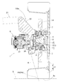
- the mechanical portion 150a of the second steering device 150 is composed of the right wheel hub unit 180 and the left wheel hub unit 185 as described above, but both the right wheel hub unit 180 and the left wheel hub unit 185 are shown in FIG. It is configured as a hub unit 1 with an auxiliary steering function.
- the hub unit 1 includes a hub bearing assembly 4 having a hub bearing 3 for supporting the wheels 2, and an auxiliary steering actuator 6.
- the hub bearing assembly 4 is supported by the knuckles 22 rotatably at two upper and lower positions via the rotation allowing supporting parts 7, 7 so as to be rotatable about an auxiliary turning axis A extending in the vertical direction.
- the auxiliary steering axis A is an axis different from the rotational axis O of the wheel 2 and is also different from the kingpin axis K which performs the main steering.
- the wheel 2 is composed of a wheel 8 and a tire 9.
- the auxiliary steering actuator 6 is fixed to the knuckle 22.
- This hub unit with auxiliary steering function is added to the steering by the first steering device 140 (see FIG. 1) of the wheels 2 and 2 serving as the front wheels, and the knuckle 22 is used as a mechanism to steer left and right wheels individually by minute angles. Will be installed.
- the suspension device 21 is a double wishbone type in this example, and has an upper arm and a lower arm connected via a shock absorber (not shown), and a king pin shaft inclined between the upper arm and the lower arm
- the knuckle 22 is installed rotatably around K.
- the suspension device 21 may adopt other various types such as an independent suspension type.
- the knuckle 22 is rotatably coupled to the tie rod 33 of the first steering device 140 (see FIG. 1).
- the hub bearing 3 includes an inner ring 12, an outer ring 11, and rolling elements 13 such as balls interposed between the inner and outer rings.
- the hub bearing 3 is an angular ball bearing in which the outer ring 11 is a fixed ring, the inner ring 12 is a rotating ring, and the rolling elements 13 are double-rowed.
- the wheel 8 of the wheel 2 is bolted to the hub flange of the inner ring 12 so as to overlap the brake rotor 14.
- the inner ring 12 rotates about the rotation axis O.
- the brake rotor 14 constitutes a brake with a brake caliper (not shown).
- assistant steering function for a non-turning wheel it is installed in the bearing mounting member for wheels (not shown) which does not have a steering function in suspension apparatus instead of attaching to knuckles.
- the hub bearing assembly 4 is a portion that rotates around the auxiliary steering axis A in the hub unit with the auxiliary steering function, and includes the hub bearing 3, the rotation-side parts of the rotation-allowable support component 7, and the auxiliary A steering force receiver (not shown) is provided.
- the rotation allowing support component 7 is a double row angular contact ball bearing in this example, but may be a spherical slide bearing or the like.
- the auxiliary turning axis A of the hub bearing assembly 4 extends in the vertical direction, but is different from the kingpin axis K, for example, in the vertical direction.
- the auxiliary turning axis A is a point at which the intersection point PK of the extension line of the kingpin axis K and the road surface S and the intersection point PA of the extension line of the auxiliary turning axis A and the road surface S are tires. It is designed to be located in the ground plane 9a. It is optimal that these intersection points PK and PA be matched with each other to minimize tire slippage.
- the auxiliary steering actuator 6 rotates the hub bearing assembly 4 around the auxiliary axis A, that is, auxiliary steering, when the linear movement output portion advances and retracts.
- the auxiliary steering actuator 6 includes an electric motor 27, a reduction gear 28 for decelerating the rotation of the electric motor 27, and a linear movement mechanism (not shown) for converting forward and reverse rotation output of the reduction gear into reciprocating linear operation And).
- the electric motor 27 is, for example, a permanent magnet type synchronous motor, but may be a direct current motor or an induction motor.
- the linear motion mechanism is a feed screw mechanism such as a slide screw or a ball screw, or a rack and pinion mechanism.
- the range of auxiliary steering of the hub bearing assembly 4 with respect to the knuckles 22 is regulated by a stopper (not shown).
- the allowable range of the auxiliary steerable angle of the hub bearing assembly 4 may be a slight angle, for example, ⁇ 5 degrees or less.
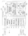
- the vehicle information detection unit 110 includes a vehicle speed detection unit 111, a steering angle detection unit 112, a vehicle height detection unit 113, an actual yaw rate detection unit 114, an actual lateral acceleration detection unit 115, an accelerator pedal sensor 116, and A brake pedal sensor 117 is provided.
- the vehicle speed detection unit 111 detects a vehicle speed based on an output of a sensor such as a speed sensor attached to the inside of a transmission provided in the vehicle, for example, and outputs vehicle speed information to the ECU 130.
- the steering angle detection unit 112 detects a steering angle based on an output of a sensor such as a resolver attached to a motor unit included in a first steering device 140 described later, for example, and outputs steering angle information to the ECU 130.
- a second steering apparatus to be described later such as a method of measuring the distance between the chassis of the vehicle 101 and the ground by a laser displacement gauge, or a method of detecting an angle of the upper arm or lower arm by an angle sensor, etc.
- the vehicle height of each wheel 2 steered by 150 is detected.
- the vehicle height detection unit 113 outputs the detected vehicle height to the ECU 130 as vehicle height information.
- the actual yaw rate detection unit 114 detects an actual yaw rate based on an output of a sensor such as a gyro sensor attached to a vehicle, for example, and outputs actual yaw rate information to the ECU 130.
- the actual lateral acceleration detection unit 115 detects an actual lateral acceleration based on an output of a sensor such as a gyro sensor attached to the vehicle 101, for example, and outputs the actual lateral acceleration information to the ECU 130.
- the accelerator pedal sensor 116 detects an input to the accelerator pedal by the driver, and outputs the detected value to the ECU 130 as an accelerator command value.
- the brake pedal sensor 117 detects an input to the brake pedal by the driver, and outputs the detected value to the ECU 130 as a brake command value.
- auxiliary steering control unit 150b of the second steering device 150 acquires vehicle information including vehicle speed information, steering angle information, vehicle height information, actual yaw rate information, actual lateral acceleration information, accelerator command value, and brake command value from the ECU 130. Do. Then, the auxiliary steering control unit 150b controls the right wheel motor control device 170 and the left wheel motor control device 175 based on the acquired vehicle information, so that the right wheel hub unit 180 and the left wheel hub are controlled. It is an apparatus which drives the electric motor 27 with which the unit 185 is equipped, and can steer the wheel on either side independently.
- the electric motor 27 may steer the wheel 2 via a transmission element capable of blocking reverse input such as a trapezoidal screw or a worm gear. Moreover, in order that the 2nd steering device 150 aims at correction
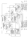
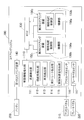
- FIG. 3 is a block diagram showing the configuration of the turning speed control unit 151.
- the turning control unit 151 includes a reference lateral acceleration calculating unit 152, a right wheel tire angle calculating unit 153, a left wheel tire angle calculating unit 154, a right wheel road surface friction coefficient calculating unit 155, and a target yaw rate calculating unit 156.
- a left wheel road surface friction coefficient calculation unit 157, a target yaw rate correction unit 158, a target left and right wheel tire angle calculation unit 159, a right wheel command value calculation unit 160, and a left wheel command value calculation unit 161 are provided.
- the right wheel tire angle calculation unit 153 and the left wheel tire angle calculation unit 154 obtain steering angle information and vehicle height information from the ECU 130 at a predetermined cycle.
- the second steering device 150 performs steering based on the acquired steering angle information and vehicle height information. Calculate the current angle of the tire (wheel 2) to be performed. Then, the right wheel tire angle calculation unit 153 and the left wheel tire angle calculation unit 154 output the calculated tire angle information to the reference lateral acceleration calculation unit 152.
- the reference lateral acceleration calculation unit 152 calculates the reference lateral acceleration based on the vehicle speed information acquired from the ECU 130 and the tire angle information input from the right wheel tire angle calculation unit 153 and the left wheel tire angle calculation unit 154. That is, based on the tire angle represented by the tire angle information from the right wheel tire angle computing unit 153 and the left wheel tire angle computing unit 154 and the vehicle speed represented by the vehicle speed information, the reference lateral acceleration computing unit 152 Perform the calculation of Then, the reference lateral acceleration calculation unit 152 outputs the calculated reference lateral acceleration to the right wheel road surface friction coefficient calculation unit 155 and the left wheel road surface friction coefficient calculation unit 157 as reference lateral acceleration information.
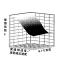
- FIG. 5 is a diagram showing characteristics as a source of the relationship included in the map for calculating the road surface friction coefficient stored in the right wheel road surface friction coefficient calculation unit 155 and the left wheel road surface friction coefficient calculation unit 157, for example.
- FIG. 10 is a characteristic diagram showing the relationship between actual lateral acceleration / reference lateral acceleration, tire angle, and friction coefficient.
- the right wheel road surface friction coefficient calculation unit 155 and the left wheel road surface friction coefficient calculation unit 157 in FIG. 3 are based on the actual lateral acceleration information acquired from the ECU 130 and the standard lateral acceleration information input from the standard lateral acceleration calculation unit 152. Calculate the coefficients. Specifically, the right wheel road surface friction coefficient calculation unit 155 and the left wheel road surface friction coefficient calculation unit 157 receive the reference lateral acceleration information from the reference lateral acceleration calculation unit 152, the right wheel tire angle calculation unit 153, and the left wheel tire angle calculation unit 154. The tire angle information is acquired, and the road surface friction coefficient is calculated from the actual lateral acceleration / standard lateral acceleration and the tire angle based on the map described using FIG. 5.
- the right wheel road surface friction coefficient calculation unit 155 and the left wheel road surface friction coefficient calculation unit 157 calculate the right wheel road surface friction coefficient information which is the calculated road surface friction coefficient of the right wheel and the left wheel road surface friction coefficient information which is the road friction coefficient of the left wheel. Is output to the target yaw rate correction unit 158.
- the target yaw rate calculation unit 156 acquires vehicle speed information and steering angle information from the ECU 130 in a predetermined cycle, and calculates a target yaw rate based on the acquired vehicle speed information and steering angle information. Then, the target yaw rate calculation unit 156 outputs the calculated target yaw rate to the target yaw rate correction unit 158 as target yaw rate information.
- the target yaw rate correction unit 158 acquires right wheel road surface friction coefficient information and left wheel road surface friction coefficient information from the right wheel road surface friction coefficient calculation unit 155 and the left wheel road surface friction coefficient calculation unit 157, and acquires target yaw rate information from the target yaw rate calculation unit 156.
- the target yaw rate is corrected according to the road surface friction coefficient represented by the right wheel road surface friction coefficient information and the left wheel road surface friction coefficient information.
- the target yaw rate correction unit 158 outputs the corrected target yaw rate to the target left and right wheel tire angle calculation unit 159 as corrected yaw rate information.
- the target left and right wheel tire angle calculation unit 159 calculates the corrected yaw rate information from the target yaw rate correction unit 158, the actual yaw rate information from the ECU 130, the accelerator command value and the brake command value, and the right wheel road surface friction coefficient calculation unit 155 Coefficient information and left wheel road surface friction coefficient information are acquired from the left wheel road surface friction coefficient calculation unit 157, and target left and right wheel tire angles, which are target values of tire angles of left and right wheels, are calculated. Specifically, the target left and right wheel tire angle calculation unit 159 calculates the target angle of each of the left and right tires based on the following formula (1).
- ⁇ y is the actual yaw rate of the vehicle represented by the actual yaw rate information
- X A is the accelerator command value
- X B is the brake command value
- ⁇ R is the right wheel road surface friction coefficient
- ⁇ L is the left wheel road surface friction coefficient
- ⁇ tR1 the target tire angle
- ⁇ tL1 of the right wheel is the target tire angle of the left wheel.
- the right wheel command value calculation unit 160 and the left wheel command value calculation unit 161 receive the target tire angle information from the target left and right wheel tire angle calculation unit 159 and the current tire from the right wheel tire angle calculation unit 153 and the left wheel tire angle calculation unit 154. Acquire tire angle information representing an angle. After acquisition, the target tire angle represented by the target tire angle information is compared with the current tire angle, and each of the right wheel hub unit 180 and the left wheel hub unit 185 is rotated according to the deviation amount that is the result of the comparison. Right wheel steering amount information and left wheel steering amount information indicating an amount to be steered are generated. Then, the right wheel command value calculation unit 160 outputs the generated right wheel steering amount information to the right wheel motor control device 170, and the left wheel command value calculation unit 161 controls the generated left wheel steering amount information for the left wheel motor Output to the device 175.
- the right wheel motor control device 170 and the left wheel motor control device 175 include inverters.
- the right wheel motor control device 170 and the left wheel motor control device 175 are based on the outputs from the right wheel command value calculation unit 160 and the left wheel command value calculation unit 161 of the turning control unit 151, and the right wheel hub unit 180 and the left wheel hub unit It controls the current to the motor of the right wheel hub unit 180 provided in 185 and the motor of the left wheel hub unit 185.
- right wheel motor control device 170 and left wheel motor control device 175 receive right wheel turning amount information and left wheel turning amount information from right wheel command value calculating unit 160 and left wheel command value calculating unit 161, respectively.
- the position information of the electric motor 27 of the right wheel hub unit 180 and the electric motor 27 of the left wheel hub unit 185 which represent the turning angles of the current right wheel hub unit 180 and the left wheel hub unit 185, is acquired.
- the target position of the electric motor is determined based on the information and the left wheel turning amount information.
- the right wheel motor control device 170 and the left wheel motor control device 175 output the current flowing to the electric motor 27 of the right wheel hub unit 180 and the electric motor 27 of the left wheel hub unit 185, and the right wheel steering angle sensor 190 and the left wheel
- the steering angle information of the right wheel hub unit 180 and the left wheel hub unit 185 is output to the turning control unit 151 from the steering angle sensor 195.
- the right wheel motor control device 170 and the left wheel motor control device 175 respectively have a left wheel abnormality detection unit 171 and a right wheel abnormality detection unit 176, and when an abnormality is detected, the second steering device 150 immediately Stop control. Specifically, the left wheel abnormality detection unit 171 and the right wheel abnormality detection unit 176 compare the left and right motor target positions respectively calculated by the right wheel motor control device 170 and the left wheel motor control device 175, and the motor target positions match. If it is, it is determined that it is operating normally. If the motor target positions do not match, it is determined that at least one is abnormal, and an abnormality signal is output to the turning control unit 151 and the other motor control devices 170 and 175. In response to the abnormal signal, the second steering device 150 immediately stops control. For example, both the turning control unit 151 and the other motor control devices 170 and 175 stop the control. Also, when the power supply of one of the motor control devices 175 and 170 fails, the control of the other motor control device 175 and 170 is stopped.
- the left wheel abnormality detection unit 171 and the right wheel abnormality detection unit 176 set the motor target position of the motor control devices 170 and 175 including itself in addition to the comparison of the left and right motor target positions, within the defined normal range When it deviates from the normal range (for example, when it is an impossible value), it outputs an abnormality signal to the turning control unit 151 and the other motor control devices 170 and 175. In response to the abnormal signal, the second steering device 150 immediately stops control.
- the steering system 100 includes the first steering device 140 that steers the wheels 2 by the operation of the steering wheel 200, and a vehicle information detection unit that detects vehicle information representing the state of the vehicle 101.
- a second steering device 150 for steering the wheel 2 by driving the electric motor 27 provided in the tire housing 105 of the vehicle is provided.
- the second steering device 150 drives the electric motor 27 based on the vehicle information detected by the vehicle information detection unit 110.
- the second steering device 150 calculates the state of the contact surface between the left and right wheels 2 and the ground according to the condition of the vehicle 101 based on the vehicle information detected by the vehicle information detection unit 110, The left and right tire angles for cornering on an ideal line 101 are calculated, and driving of the left and right electric motors is performed individually.
- the second steering device 150 when the vehicle 101 moves in an unintended direction due to sliding or the like at cornering, the direction of the vehicle 101 is adjusted in accordance with the operation amount of the steering wheel 200. It becomes possible to correct. Further, since the second steering device 150 is an independent steering device, it is possible to individually adjust the left and right toe angles, and it is possible to improve the straight running stability during normal driving and the steering stability in cornering. It is possible to improve the quality.
- cornering becomes possible on the ideal line by correcting the steering amount of each of the left and right so that the driver's steering wheel operation can be more efficiently curved according to the vehicle information. Since the steering wheel operation load of the person can be reduced, the steering stability of the vehicle 101 is improved. With regard to straight-ahead stability, in the conventional vehicle, when the vehicle is slightly shaken, the driver needs to perform correction steering in order to correct the fluctuation.
- the second steering device 150 according to this embodiment In the vehicle 101 equipped with the above, even if the driver does not operate the steering wheel 200, it is possible to correct the wander of the vehicle 101. Therefore, the straight running stability of the vehicle 101 is improved.
- the second steering device 150 independently controlled by the left and right mutually monitors the abnormal state of each of the left and right motor control devices 175 and 170, and an abnormality occurs in one of the motor control devices 175 and 170. If so, the control of the motor control devices 175 and 170 is immediately stopped. Even if the control is stopped, the steering range of the second steering device 150 is limited to about a few degrees, and if the reverse input from the road surface is prevented by a trapezoidal screw or the like, the hub unit 180, Stabilization of 185 can be prevented, and the vehicle 101 can be moved to a state where it can be reliably stopped by the driver's steering wheel operation, and safety can be ensured.
- FIG. 6 is an explanatory view showing an overview of a steering system 100 according to this embodiment
- FIG. 7 is a block diagram showing the configuration thereof.
- the steering system 100 according to this embodiment differs from the first embodiment in that the first steering system 140 and the second steering system 150 steer different wheels 2. That is, in the steering system 100 according to this embodiment, the first steering system 140 steers the wheels 2 serving as the front wheels of the vehicle 101, and the second steering system 150 serves as the wheels 2 serving as the rear wheels of the vehicle. Do the helm.
- FIG. 8 is a block diagram showing the configuration of the turning speed control unit 151 according to this embodiment.
- the turning control unit 151 acquires vehicle speed information, steering angle information, actual yaw rate information, actual lateral acceleration information, accelerator command value, and brake command value as vehicle information from the ECU 130, and the right wheel motor control device 170 and left wheel motor control Control of the device 175 is performed.
- the target left and right wheel tire angle calculation unit 159 of the turning control unit 151 according to this embodiment calculates the target angle of each of the left and right tires based on the following equation (2).
- the second steering system 150 can steer the steering angle of the first steering system 140.
- the vehicle can be steered in accordance with the vehicle speed, and the traveling stability of the vehicle can be improved.
- FIG. 9 is an explanatory view showing a conceptual configuration of a vehicle equipped with the steering system 100 according to this embodiment
- FIG. 10 is a block diagram showing the configuration of the steering system 100.
- the steering system 100 according to this embodiment is different from the steering system 100 according to the first embodiment in that two second steering devices 150 1 and 150 2 are provided.
- the second steering device 150 1 on one performs the turning of the same wheel 2 and the first steering device 140
- the second steering device 150 2 on the other different from the first steering device 140
- the wheels 2 are steered.
- the second steering device 150 1 on one performs the same operation as the second steering device 150 according to the first embodiment, the second steering device 150 2 on the other, to a second embodiment The same operation as that of the second steering device 150 is performed.
- the steering system 100 according to this embodiment includes the plurality of second steering devices 150 1 and 150 2 so that it is possible to independently steer the four wheels at a higher altitude, and the vehicle It is possible to improve the running stability of 101.
- the steering command device is the steering wheel 200
- a manual steering command device other than the steering wheel 200 for example, a joystick may be used.
- FIG. It may be an automatic steering command device 200A as another embodiment.
- the steering command device 200A of FIG. 11 is a device that recognizes the vehicle peripheral status and the like from the vehicle peripheral status detecting means 230 and automatically generates a steering command.
- the vehicle peripheral situation detection means 230 is, for example, a sensor such as a camera or a millimeter wave radar.
- the steering command device 200A recognizes, for example, a white line or an obstacle on a road, and shapes and outputs a steering command.
- the steering command device 200A may be part of a device that performs automatic driving of the vehicle 101 or may be a device that supports steering by manual driving.
Landscapes
- Engineering & Computer Science (AREA)
- Chemical & Material Sciences (AREA)
- Combustion & Propulsion (AREA)
- Transportation (AREA)
- Mechanical Engineering (AREA)
- Steering Control In Accordance With Driving Conditions (AREA)
- Steering-Linkage Mechanisms And Four-Wheel Steering (AREA)
- Power Steering Mechanism (AREA)
Abstract
操舵量指令により操舵される車両の向き対して車両の状態に応じてその補正を可能とし、車両の走行安定性を維持する。操舵指令装置(200)が出力する操舵の指令に従い車両(101)の車輪を転舵させる第1のステアリング装置(140)の他に、第2のステアリング装置(150)を備える。第2のステアリング装置(150)は、タイヤハウジング内に設けられ電動モータ(27)の駆動により車輪(2)を転舵させる機構部(150a)、および前記電動モータ(27)を制御する制御部(150b)からなる。この制御部(150b)は、車両情報検出部(110)により検知される車両(101)の状態を表す車両情報に基づいて、前記電動モータ(27)を制御する。
Description
本出願は、2017年9月27日出願の特願2017-185869の優先権を主張するものであり、その全体を参照により本願の一部をなすものとして引用する。
この発明は、車両に設けられるステアリングシステムに関するものであり、特に、運転者や操舵支援装置等の操作により車輪を転舵させるステアリング装置の他に、補助転舵用のステアリング装置を備えるステアリングシステムに関する。
自動車に代表される車両においては、ハンドルとステアリング装置とが機械的に接続され、ハンドルに対する回転操作により、ステアリング装置が車輪の転舵を行う。
しかしながら、ハンドルとステアリング装置とが機械的に接続されている車両においては、路面の凹凸などによる車輪からの逆入力により、ハンドルがとられ、車両がふらついてしまうという問題がある。またコーナリング時においては、運転者の習熟度や、路面等の環境条件のバラつきで、走行安定性やハンドル操作に対する追従性が低下するという問題がある。
ハンドル操作によらずに、道路の方向や障害物等の車両周辺状況等をセンサ類により認識して操舵指令を自動生成する操舵指令装置を備えた自動または半自動運転の車両があるが、前記車輪からの逆入力があった場合に、前記の車両のふらつきを生じる恐れがあり、車両進行方向を大きく変更することを可能としたステアリング装置の制御だけでは、車両の走行安定性を維持することが難しい。
この発明は、上記の問題に鑑みてなされたものであり、その目的は、操舵量指令により操舵される車両の向きに対して車両の状態に応じてその補正を可能とし、車両の走行安定性を維持することが可能であり、さらに前記補正を行うにつき、制御出力の異常監視機能を備え、装置の異常により却って走行安定性を低下させることを未然に防止できるステアリングシステムを提供することである。
以下、本発明について、理解を容易にするために、便宜上実施形態の符号を参照して説明する。
この発明のステアリングシステム100は、車両101が備えるステアリングシステムであって、
操舵指令装置200,200Aが出力する操舵量の指令に従い前記車両101を転舵させる第1のステアリング装置140と、
前記車両101の左右のタイヤハウジング105内にそれぞれ設けられ電動モータ27の駆動により補助転舵として車輪2を転舵させる左右の機構部150a,150a、およびこれら左右の機構部150a,150aを制御する一つの補助転舵制御部150bを有する第2のステアリング装置150と、
前記車両101の状態を表す車両情報を検出する車両情報検出部110とを備え、
前記第2のステアリング装置150の前記補助転舵制御部150bは、
前記車両情報および前記左右の機構部150a,150aの転舵角の情報に基づき前記左右の機構部150a,150aに行わせる補助転舵の指令を生成する旋回制御部151と、前記補助転舵の指令に従い前記左右の機構部150a,150aの前記電動モータ27,27をそれぞれ制御する左輪用および右輪用のモータ制御装置175,170とを有し、
前記左輪用および右輪用のモータ制御装置175,170は、それぞれ異常検出部176,171を有し、これら異常検出部176,171は、相互に状態を監視する。
操舵指令装置200,200Aが出力する操舵量の指令に従い前記車両101を転舵させる第1のステアリング装置140と、
前記車両101の左右のタイヤハウジング105内にそれぞれ設けられ電動モータ27の駆動により補助転舵として車輪2を転舵させる左右の機構部150a,150a、およびこれら左右の機構部150a,150aを制御する一つの補助転舵制御部150bを有する第2のステアリング装置150と、
前記車両101の状態を表す車両情報を検出する車両情報検出部110とを備え、
前記第2のステアリング装置150の前記補助転舵制御部150bは、
前記車両情報および前記左右の機構部150a,150aの転舵角の情報に基づき前記左右の機構部150a,150aに行わせる補助転舵の指令を生成する旋回制御部151と、前記補助転舵の指令に従い前記左右の機構部150a,150aの前記電動モータ27,27をそれぞれ制御する左輪用および右輪用のモータ制御装置175,170とを有し、
前記左輪用および右輪用のモータ制御装置175,170は、それぞれ異常検出部176,171を有し、これら異常検出部176,171は、相互に状態を監視する。
この構成によれば、モータ駆動される第2のステアリング装置150を備え、第2のステアリング制御装置150の制御部150bは車両情報に基づいて前記電動モータ27を制御する。そのため、滑りなどによって車両101が意図しない方向に移動する場合に、前記車両情報により得られる車両101の状態に応じて、例えば前記操舵指令装置200,200Aが出力する操舵量や車速に合わせて、車両101の向きを補正することが可能となる。このため、第1のステアリング装置140だけでは対処が困難な車両101のふらつきを補正することが可能となる。これにより、車両101の安定性が向上する。
また、前記第2のステアリング装置150の制御部である補助転舵制御部150bは、左右の機構部150a,150aの前記電動モータ27,27を制御する左輪用および右輪用のモータ制御装置175,170とを有しているが、これらモータ制御装置175,170は、それぞれ異常検出部176,171を有し、両異常検出部176,171は、相互監視を行うことにより両モータ制御装置175,170の少なくとも一方が異常であると判定する。例えば、いずれか片方のモータ制御装置175,170の電源が失陥してしまった場合、もう片方のモータ制御装置175,170の制御を停止することで、運転者は安全にハンドルを使って、路肩など安全な場所に車両を移動させることができる。これと同様に、片方のモータ制御装置175,170が目標角度とは異なる異常な動作をした場合は、両方のモータ制御装置175,170の制御を停止することで、運転者のハンドル操作によって車両を確実に停止できる状態まで移動させることができ、安全を確保することができる。
この発明において、前記操舵指令装置200,200Aが、運転者により操舵の操作がなされる手動の装置、例えばハンドル200であってもよい。この場合、モータ駆動される第2のステアリング装置150を備え、第2のステアリング装置150の制御部150bは車両情報に基づいて前記電動モータ27を制御するため、滑りなどによって車両101が意図しない方向に移動する場合に、前記車両情報により得られる車両101の状態に応じて、例えばハンドル200の操作量に合わせて、車両101の向きを補正することが可能となる。このため、運転者がハンドル200の操作を行わなくても、車両101のふらつきを補正することが可能となる。これにより、車両101の安定性が向上する。
この発明において、前記第1のステアリング装置140は、左右の車輪2を連動して転舵させる装置であり、前記第2のステアリング装置150は、左右の車輪2を独立して転舵可能な装置であってもよい。第1のステアリング装置140が左右の車輪2を連動して転舵させる構成であることで、運転者のハンドル200の操作による車両101の向きの調整や、自動の操舵指令装置200Aによる車両101の向きの調整が、従来の車両101と同様に行える。第2のステアリング装置150は、左右の車輪2を独立して転舵可能であるため、トー角を調整することが可能であって、これによりハンドル操作の機敏性や自動の操舵指令装置200Aによる制御の機敏性等を車両101の状態に応じて調整できる。
この発明において、前記第1のステアリング装置140と、前記第2のステアリング装置150とは、同一の車輪2の転舵を行う装置であってもよい。例えば、第1のステアリング装置140で前輪の転舵を行う場合に、第1のステアリング装置140の転舵による転舵角に対して、第2のステアリング装置150により、その転舵角の微調整を行うようにしてもよい。
この発明において、前記第1のステアリング装置140と、前記第2のステアリング装置150とは、互いに異なる車輪2を転舵させる装置であってもよい。例えば第1のステアリング装置140が前輪転舵を行う装置である場合に、第2のステアリング装置150が後輪転舵を行う装置であってもよい。この構成の場合、第1のステアリング装置140と第2のステアリング装置150とが同じ車輪2を転舵させる構成とする場合に比べて、機構部150aの構成が簡素にできる。
この発明において、前記車両情報は、車速の情報、操舵角の情報、車高の情報、実ヨーレートの情報、実横加速度の情報、アクセル指令値、およびブレーキ指令値を含む情報であってもよい。車両101の状態の情報として、車速の情報、操舵角の情報、車高の情報、実ヨーレートの情報、実横加速度の情報、アクセル指令値、およびブレーキ指令値を用いると、車両101の状態に応じた第2のステアリング装置150の制御がより一層適切に行え、さらなる車両101の安定性の向上等が得られる。なお、本明細書において、車速の情報を「車速情報」、操舵角の情報を「操舵角情報」、車高の情報を「車高情報」、実ヨーレートの情報を「実ヨーレート情報」、実横加速度の情報を「実横加速度情報」と称する場合がある。
この発明において、前記第2のステアリング装置150を2つ備え、一方の前記第2のステアリング装置1501と、前記第1のステアリング装置140とは同一の車輪2の転舵を行い、他方の前記第2のステアリング装置1502と、前記第1のステアリングシステム140とは互いに異なる車輪2の転舵を行うものであってもよい。このように、ステアリングシステム100が複数の第2のステアリング装置1501,1502を備えていることにより、より高度に4輪を独立して転舵することが可能となり、車両101の走行安定性をより一層向上させることが可能となる。
この発明において、前記両モータ制御装置175,170の前記異常検出部176,171は、左右各々の前記モータ制御装置175,170において右輪転舵量情報および左輪転舵量情報に基づいて演算されたモータ目標位置を比較し、演算結果が不一致の場合、少なくとも一方が異常であると判定するようにしてもよい。両演算結果のモータ目標位置は一致しているべきであり、不一致の場合は異常である。この一致か不一致かにより判定することで、容易に異常の判定が行える。
この発明において、前記第2のステアリング装置150の前記補助転舵制御部150bは、前記異常検出部176,171による異常判定の結果、異常と判定されたときには、即時に制御を中止するようにしてもよい。制御を停止することで、補助転舵が行われず、第1のステアリング装置だけで転舵が行われる。補助転舵の機能を失った状態となるだけであり、操舵指令装置200,200Aが出力する操舵量の指令による転舵は行われるので、前記制御が停止されても、走行上の支障はない。
請求の範囲および/または明細書および/または図面に開示された少なくとも2つの構成のどのような組合せも、本発明に含まれる。特に、請求の範囲の各請求項の2つ以上のどのような組合せも、本発明に含まれる。
この発明は、添付の図面を参考にした以下の好適な実施形態の説明から、より明瞭に理解されるであろう。しかしながら、実施形態および図面は単なる図示および説明のためのものであり、この発明の範囲を定めるために利用されるべきものではない。この発明の範囲は添付の請求の範囲によって定まる。添付図面において、複数の図面における同一の符号は、同一または相当する部分を示す。
[実施形態1]
この発明の第1の実施形態を図1ないし図5と共に説明する。図1は、この実施形態に係るステアリングシステム100を搭載した自動車等の車両101の概念構成を示す説明図である。車両101は、前輪となる左右の車輪2,2と、後輪となる左右の車輪2,2とを有する4輪車両であり、駆動方式は、前輪駆動、後輪駆動、4輪駆動のいずれであってもよい。
この発明の第1の実施形態を図1ないし図5と共に説明する。図1は、この実施形態に係るステアリングシステム100を搭載した自動車等の車両101の概念構成を示す説明図である。車両101は、前輪となる左右の車輪2,2と、後輪となる左右の車輪2,2とを有する4輪車両であり、駆動方式は、前輪駆動、後輪駆動、4輪駆動のいずれであってもよい。
このステアリングシステム100は、車両101の転舵を行うためのシステムであり、第1のステアリング装置140と、第2のステアリング装置150と、車両情報検出部110とを備える。第1のステアリング装置140は、ハンドル200等の操舵指令装置に対する運転者の操作により、車両101の転舵輪となる車輪2,2を転舵させる装置であり、この実施形態では前輪操舵形式とされている。
第2のステアリング装置150は、車両状態に応じた制御によって補助的な転舵を行う装置であり、機構部150aと補助転舵制御部150bとでなる。機構部150aは、補助転舵の対象となる車輪2,2毎に設けられる機構であり、車両101のタイヤハウジング105内に設けられて電動モータ27の駆動により車輪2を転舵させる。補助転舵制御部150bは、電動モータ27を、車両情報検出部110により検出された車両の状態を表す車両情報に基づいて制御する。車両情報検出部110は、車両の状態を検出する手段であり、各種のセンサ類の群を称している。車両情報検出部110の検出した車両情報は、メインのECU130を介して第2のステアリング装置150の制御部150bに転送される。
<ECU130の構成>
ECU(Electronic Control Unit)130は、車両101の全体の協調制御や統括制御を行う制御装置であり、VCU(Vehicle Control Unit)とも称される。ECU130は、車両情報検出部110から入力される車速情報、操舵角情報、車高情報、実ヨーレート情報、実横加速度情報、アクセル指令値、およびブレーキ指令値に基づいて、第2のステアリング装置150を制御する。
ECU(Electronic Control Unit)130は、車両101の全体の協調制御や統括制御を行う制御装置であり、VCU(Vehicle Control Unit)とも称される。ECU130は、車両情報検出部110から入力される車速情報、操舵角情報、車高情報、実ヨーレート情報、実横加速度情報、アクセル指令値、およびブレーキ指令値に基づいて、第2のステアリング装置150を制御する。
<第1のステアリング装置140の構成>
第1のステアリング装置140は、上記のように運転者によるハンドル200に対する入力に応じて、車両101の前輪となる左右の車輪2,2を連動して転舵させるシステムであり、ステアリングシャフト32、ラックアンドピニオン(図示せず)、タイロッド33等、周知の機械的な構成を備える。運転者がハンドル200に対して回転入力を行うと、ステアリングシャフト32も連動して回転する。ステアリングシャフト32が回転すると、ラックアンドピニオンによってステアリングシャフト32と連結されているタイロッド33が車幅方向に移動することで、車輪2の向きが変わり、左右の車輪2,2を連動して転舵することが可能である。
第1のステアリング装置140は、上記のように運転者によるハンドル200に対する入力に応じて、車両101の前輪となる左右の車輪2,2を連動して転舵させるシステムであり、ステアリングシャフト32、ラックアンドピニオン(図示せず)、タイロッド33等、周知の機械的な構成を備える。運転者がハンドル200に対して回転入力を行うと、ステアリングシャフト32も連動して回転する。ステアリングシャフト32が回転すると、ラックアンドピニオンによってステアリングシャフト32と連結されているタイロッド33が車幅方向に移動することで、車輪2の向きが変わり、左右の車輪2,2を連動して転舵することが可能である。
<第2のステアリング装置150の構成概略>
第2のステアリング装置150は、左右の車輪2,2を独立して転舵可能な装置であり、その機構部150aとして右輪ハブユニット180(図2)および左輪ハブユニット185を備える。これら右輪ハブユニット180および左輪ハブユニット185は、タイヤハウジング105内に設けられた補助転舵用アクチュエータ6(図4)の電動モータ27により車輪の転舵を行う。なお、この実施形態では、第1のステアリング装置140と、第2のステアリング装置150とは、同一の車輪を転舵する場合、すなわち前輪2,2を転舵する場合について説明する。
第2のステアリング装置150は、左右の車輪2,2を独立して転舵可能な装置であり、その機構部150aとして右輪ハブユニット180(図2)および左輪ハブユニット185を備える。これら右輪ハブユニット180および左輪ハブユニット185は、タイヤハウジング105内に設けられた補助転舵用アクチュエータ6(図4)の電動モータ27により車輪の転舵を行う。なお、この実施形態では、第1のステアリング装置140と、第2のステアリング装置150とは、同一の車輪を転舵する場合、すなわち前輪2,2を転舵する場合について説明する。
<第2のステアリング装置150の機構部150aの具体的構成例>
第2のステアリング装置150の機構部150aは、前記のように右輪ハブユニット180および左輪ハブユニット185からなるが、これら右輪ハブユニット180および左輪ハブユニット185は、いずれも、図4に示す補助転舵機能付きのハブユニット1として構成されている。このハブユニット1は、車輪2の支持用のハブベアリング3を有するハブベアリング部組立部品4と、補助転舵用アクチュエータ6とを備える。ハブベアリング部組立部品4は、上下方向に延びる補助転舵軸心A回りに回転自在に、上下2箇所で回転許容支持部品7,7を介してナックル22に支持されている。補助転舵軸心Aは、車輪2の回転軸心Oとは異なる軸心であり、主な転舵を行うキングピン軸Kとも異なっている。車輪2は、ホイール8とタイヤ9とでなる。補助転舵用アクチュエータ6は、ナックル22に固定されている。
第2のステアリング装置150の機構部150aは、前記のように右輪ハブユニット180および左輪ハブユニット185からなるが、これら右輪ハブユニット180および左輪ハブユニット185は、いずれも、図4に示す補助転舵機能付きのハブユニット1として構成されている。このハブユニット1は、車輪2の支持用のハブベアリング3を有するハブベアリング部組立部品4と、補助転舵用アクチュエータ6とを備える。ハブベアリング部組立部品4は、上下方向に延びる補助転舵軸心A回りに回転自在に、上下2箇所で回転許容支持部品7,7を介してナックル22に支持されている。補助転舵軸心Aは、車輪2の回転軸心Oとは異なる軸心であり、主な転舵を行うキングピン軸Kとも異なっている。車輪2は、ホイール8とタイヤ9とでなる。補助転舵用アクチュエータ6は、ナックル22に固定されている。
この補助転舵機能付ハブユニットは、前輪となる車輪2,2の第1のステアリング装置140(図1参照)による転舵に付加して左右輪個別に微小角転舵させる機構としてナックル22に設置される。懸架装置21は、この例ではダブルウイッシュボーン式であり、ショックアブソーバ(図示せず)を介して接続されたアッパーアームとロアアームとを有し、これらアッパーアームとロアアームの先端間で傾斜したキングピン軸K回りに回動自在に前記ナックル22が設置されている。懸架装置21は、この他に独立懸架式など、他の種々の形式が採用できる。ナックル22は、第1のステアリング装置140(図1参照)のタイロッド33に回転可能に連結されている。
ハブベアリング3は、内輪12と外輪11とこれら内外輪間に介在したボール等の転動体13とで構成されている。ハブベアリング3は、図示の例では、外輪11が固定輪、内輪12が回転輪となり、転動体13が複列とされたアンギュラ玉軸受とされている。内輪12のハブフランジに、車輪2のホイール8がブレーキロータ14と重なり状態でボルト固定されている。内輪12は、回転軸心O回りに回転する。ブレーキロータ14は、ブレーキキャリパ(図示せず)とでブレーキを構成する。なお、補助転舵機能付ハブユニット1を非転舵輪に用いる場合は、ナックル22に取付ける代わりに、懸架装置における転舵機能を持たない車輪用軸受取付け部材(図示せず)に設置される。
ハブベアリング部組立部品4は、この補助転舵機能付きのハブユニットにおける補助転舵軸心A周りに回転する部分であり、ハブベアリング3と、前記回転許容支持部品7の回転側部品と、補助転舵力受け部(図示せず)とを備える。回転許容支持部品7は、この例では複列アンギュラ玉軸受とされているが、球面滑り軸受等であってもよい。
ハブベアリング部組立部品4の補助転舵軸心Aは、上下方向に延びるが、キングピン軸Kとは異なる方向であり、例えば鉛直方向である。この実施形態では、補助転舵軸心Aは、キングピン軸Kの延長線と路面Sとの交点位置PKと、補助転舵軸心Aの延長線と路面Sとの交点位置PAが、共にタイヤ接地面9a内に位置するように設計されている。これらの交点位置PK,PAは、互いに一致していることが、タイヤのすべりを最小とするために最適である。
補助転舵用アクチュエータ6は、その直動出力部が進退することで、ハブベアリング部組立部品4を前記補助軸心A回りに回転、つまり補助転舵させる。補助転舵用アクチュエータ6は、電動モータ27と、この電動モータ27の回転を減速する減速機28と、この減速機の正逆の回転出力を往復直線動作に変換する直動機構(図示せず)とで構成される。電動モータ27は、例えば永久磁石型同期モータとされるが、直流モータであっても、誘導モータであってもよい。前記直動機構は、滑りねじまたはボールねじ等の送りねじ機構、またはラック・ピニオン機構等とされる。
ハブベアリング部組立部品4のナックル22に対する補助転舵の範囲は、ストッパ(図示せず)により規制される。ハブベアリング部組立部品4の補助転舵可能角度の許容範囲は、僅かな角度でよく、例えば±5度以下とされる。
<車両情報検出部110の構成概略>
図2に示すように、車両情報検出部110は、車速検出部111、操舵角検出部112、車高検出部113、実ヨーレート検出部114、実横加速度検出部115、アクセルペダルセンサ116、およびブレーキペダルセンサ117を備える。車速検出部111は、例えば車両が備えるトランスミッションの内部に取り付けられたスピードセンサ等のセンサの出力に基づいて、車速を検出し、ECU130へ車速情報を出力する。操舵角検出部112は、例えば後述する第1のステアリング装置140が備えるモータ部に取り付けられたレゾルバ等のセンサの出力に基づいて操舵角を検出し、ECU130へ操舵角情報を出力する。
図2に示すように、車両情報検出部110は、車速検出部111、操舵角検出部112、車高検出部113、実ヨーレート検出部114、実横加速度検出部115、アクセルペダルセンサ116、およびブレーキペダルセンサ117を備える。車速検出部111は、例えば車両が備えるトランスミッションの内部に取り付けられたスピードセンサ等のセンサの出力に基づいて、車速を検出し、ECU130へ車速情報を出力する。操舵角検出部112は、例えば後述する第1のステアリング装置140が備えるモータ部に取り付けられたレゾルバ等のセンサの出力に基づいて操舵角を検出し、ECU130へ操舵角情報を出力する。
車高検出部113は、車両101のシャーシと地面との距離をレーザ変位計により測定する方法、あるいは前記アッパーアームまたはロアアームの角度を角度センサにより検出する方法等により、後述する第2のステアリング装置150により転舵される各車輪2の車高を検出する。そして車高検出部113は、検出した車高を車高情報としてECU130へ出力する。実ヨーレート検出部114は、例えば車両に取り付けられたジャイロセンサ等のセンサの出力に基づいて、実ヨーレートを検出し、ECU130へ実ヨーレート情報を出力する。実横加速度検出部115は、例えば車両101に取り付けられたジャイロセンサ等のセンサの出力に基づいて、実横加速度を検出し、ECU130へ実横加速度情報を出力する。
アクセルペダルセンサ116は、運転者によるアクセルペダルへの入力を検出し、検出した値をアクセル指令値としてECU130へ出力する。ブレーキペダルセンサ117は、運転者によるブレーキペダルへの入力を検出し、検出した値をブレーキ指令値としてECU130へ出力する。
<第2のステアリング装置150の補助転舵制御部150b>
第2のステアリング装置150の補助転舵制御部150bは、ECU130から車速情報、操舵角情報、車高情報、実ヨーレート情報、実横加速度情報、アクセル指令値、およびブレーキ指令値を含む車両情報取得する。そして、補助転舵制御部150bは、取得した車両情報に基づいて、旋回制御部151が右輪モータ制御装置170、左輪モータ制御装置175を制御することで、右輪ハブユニット180、および左輪ハブユニット185が備える電動モータ27を駆動し、左右の車輪を独立して転舵可能な装置である。なお、前記電動モータ27は、台形ネジやウォームギヤ等の逆入力を遮断できる伝達要素を介して、車輪2を転舵してもよい。また、第2のステアリング装置150は、車輪2の向きの補正を目的とするため、転舵の範囲は±数度に制限されている。
第2のステアリング装置150の補助転舵制御部150bは、ECU130から車速情報、操舵角情報、車高情報、実ヨーレート情報、実横加速度情報、アクセル指令値、およびブレーキ指令値を含む車両情報取得する。そして、補助転舵制御部150bは、取得した車両情報に基づいて、旋回制御部151が右輪モータ制御装置170、左輪モータ制御装置175を制御することで、右輪ハブユニット180、および左輪ハブユニット185が備える電動モータ27を駆動し、左右の車輪を独立して転舵可能な装置である。なお、前記電動モータ27は、台形ネジやウォームギヤ等の逆入力を遮断できる伝達要素を介して、車輪2を転舵してもよい。また、第2のステアリング装置150は、車輪2の向きの補正を目的とするため、転舵の範囲は±数度に制限されている。
<旋回制御部151の制御>
次に、旋回制御部151が行う制御について説明する。図3は、旋回速度制御部151の構成を示すブロック図である。同図に示すように、旋回制御部151は、規範横加速度計算部152、右輪タイヤ角度計算部153、左輪タイヤ角度計算部154、右輪路面摩擦係数計算部155、目標ヨーレート計算部156、左輪路面摩擦係数計算部157、目標ヨーレート補正部158、目標左右輪タイヤ角度計算部159、右輪指令値計算部160、および左輪指令値計算部161を備える。
次に、旋回制御部151が行う制御について説明する。図3は、旋回速度制御部151の構成を示すブロック図である。同図に示すように、旋回制御部151は、規範横加速度計算部152、右輪タイヤ角度計算部153、左輪タイヤ角度計算部154、右輪路面摩擦係数計算部155、目標ヨーレート計算部156、左輪路面摩擦係数計算部157、目標ヨーレート補正部158、目標左右輪タイヤ角度計算部159、右輪指令値計算部160、および左輪指令値計算部161を備える。
右輪タイヤ角度計算部153および左輪タイヤ角度計算部154は、所定の周期で、ECU130から操舵角情報および車高情報を取得する。右輪タイヤ角度計算部153および左輪タイヤ角度計算部154は、操舵角情報および車高情報を取得すると、取得した操舵角情報および車高情報に基づいて、第2のステアリング装置150が転舵を行うタイヤ(車輪2)の現在の角度を算出する。そして、右輪タイヤ角度計算部153および左輪タイヤ角度計算部154は、算出したタイヤ角度情報を規範横加速計算部152に出力する。
規範横加速度計算部152は、ECU130から取得した車速情報、ならびに右輪タイヤ角度計算部153および左輪タイヤ角度計算部154から入力されるタイヤ角度情報に基づいて、規範横加速度の計算を行う。すなわち、規範横加速度計算部152は、右輪タイヤ角度計算部153および左輪タイヤ角度計算部154からタイヤ角度情報で表されるタイヤ角度、車速情報で表される車速とに基づいて、規範横加速度の計算を行う。そして、規範横加速度計算部152は、算出した規範横加速度を規範横加速度情報として右輪路面摩擦係数算出部155および左輪路面摩擦係数計算部157に出力する。
図5は、例えば、右輪路面摩擦係数計算部155および左輪路面摩擦係数計算部157に記憶されている路面摩擦係数を算出するためのマップに含まれる関係の元となる特性を表す図であり、実横加速度/規範横加速度と、タイヤ角度と、摩擦係数との関係を表す特性図である。
図3の右輪路面摩擦係数計算部155および左輪路面摩擦係数計算部157は、ECU130から取得する実横加速度情報および規範横加速度計算部152から入力される規範横加速度情報に基づいて、路面摩擦係数の計算を行う。具体的には、右輪路面摩擦係数計算部155および左輪路面摩擦係数計算部157は、規範横加速度計算部152から規範横加速度情報と、右輪タイヤ角度計算部153および左輪タイヤ角度計算部154からタイヤ角度情報を取得し、図5を用いて説明したマップに基づいて、実横加速度/規範横加速度とタイヤ角度とから、路面摩擦係数を算出する。そして、右輪路面摩擦係数計算部155および左輪路面摩擦係数計算部157は、算出した右輪の路面摩擦係数である右輪路面摩擦係数情報と、左輪の路面摩擦係数である左輪路面摩擦係数情報を目標ヨーレート補正部158に出力する。
目標ヨーレート計算部156は、所定の周期でECU130から車速情報および操舵角情報を取得し、取得する車速情報および操舵角情報に基づいて、目標ヨーレートを計算する。そして、目標ヨーレート計算部156は、算出した目標ヨーレートを目標ヨーレート情報として目標ヨーレート補正部158に出力する。
目標ヨーレート補正部158は、右輪路面摩擦係数計算部155および左輪路面摩擦係数計算部157から、右輪路面摩擦係数情報および左輪路面摩擦係数情報と、目標ヨーレート計算部156から目標ヨーレート情報を取得し、右輪路面摩擦係数情報および左輪路面摩擦係数情報で表される路面摩擦係数に応じて目標ヨーレートの補正を行う。そして、目標ヨーレート補正部158は、補正後の目標ヨーレートを補正後ヨーレート情報として目標左右輪タイヤ角度計算部159へ出力する。
目標左右輪タイヤ角度計算部159は、目標ヨーレート補正部158から補正後ヨーレート情報と、ECU130から実ヨーレート情報、アクセル指令値およびブレーキ指令値と、右輪路面摩擦係数計算部155から右輪路面摩擦係数情報、左輪路面摩擦係数計算部157から左輪路面摩擦係数情報を取得し、左右輪のタイヤ角度の目標値である目標左右輪タイヤ角度を計算する。具体的には、目標左右輪タイヤ角度計算部159は、下記式(1)に基づいて、左右それぞれのタイヤの目標の角度を算出する。

ここで、θyは実ヨーレート情報で表される実際の車両のヨーレート量、XAはアクセル指令値、XBはブレーキ指令値、μRは右輪路面摩擦係数、μLは左輪路面摩擦係数、θtR1は、右輪の目標タイヤ角度、θtL1は、左輪の目標タイヤ角度である。そして、目標左右輪タイヤ角度計算部159は、計算した左右輪それぞれの目標タイヤ角度を目標タイヤ角度情報として、右輪指令値計算部160および左輪指令値計算部161へ出力する。
右輪指令値計算部160および左輪指令値計算部161は、目標左右輪タイヤ角度計算部159から目標タイヤ角度情報を、右輪タイヤ角度計算部153および左輪タイヤ角度計算部154から、現在のタイヤ角度を表すタイヤ角度情報を取得する。取得後、目標タイヤ角度情報で表される目標タイヤ角度と、現在のタイヤ角度とを比較し、該比較の結果である偏差量に応じて右輪ハブユニット180および左輪ハブユニット185のそれぞれを転舵させる量を表す右輪転舵量情報および左輪転舵量情報を生成する。そして、右輪指令値計算部160は、生成した右輪転舵量情報を右輪用モータ制御装置170へ出力し、左輪指令値計算部161は、生成した左輪転舵量情報を左輪用モータ制御装置175へと出力する。
右輪モータ制御装置170および左輪モータ制御装置175は、インバータを備える。右輪モータ制御装置170および左輪モータ制御装置175は、旋回制御部151の右輪指令値計算部160および左輪指令値計算部161からの出力に基づいて、右輪ハブユニット180、および左輪ハブユニット185が備える右輪ハブユニット180のモータ、および左輪ハブユニット185のモータへの電流を制御する。具体的には、右輪モータ制御装置170および左輪モータ制御装置175は、右輪指令値計算部160および左輪指令値計算部161から右輪転舵量情報および左輪転舵量情報が入力されると、現在の右輪ハブユニット180、および左輪ハブユニット185の転舵角を表す右輪ハブユニット180の電動モータ27、および左輪ハブユニット185の電動モータ27の位置情報を取得し、右輪転舵量情報および左輪転舵量情報に基づいて当該電動モータの目標位置を決定する。そして、右輪モータ制御装置170および左輪モータ制御装置175は、右輪ハブユニット180の電動モータ27、および左輪ハブユニット185の電動モータ27へ流す電流を出力し、右輪舵角センサ190および左輪舵角センサ195より、旋回制御部151に、右輪ハブユニット180および左輪ハブユニット185の舵角情報を出力する。
また、右輪モータ制御装置170および左輪モータ制御装置175は、それぞれ左輪異常検出部171および右輪異常検出部176を有し、異常が検出された場合は、第2のステアリング装置150は即時に制御を停止する。具体的には、左輪異常検出部171および右輪異常検出部176は、右輪モータ制御装置170および左輪モータ制御装置175でそれぞれ計算した左右のモータ目標位置を比較し、モータ目標位置が一致していた場合は正常に動作していると判断する。モータ目標位置が不一致であった場合は、少なくとも一方が異常であると判断して、旋回制御部151および他方のモータ制御装置170,175へ異常信号を出力する。この異常信号に応答して、第2のステアリング装置150は即時に制御を停止する。例えば、旋回制御部151および他方のモータ制御装置170,175のいずれもが制御を中止する。また、いずれか一方のモータ制御装置175,170の電源が失陥してしまった場合も、他方のモータ制御装置175,170の制御を停止する
左輪異常検出部171および右輪異常検出部176は、左右のモータ目標位置の比較の他に、自己を含むモータ制御装置170,175の前記モータ目標位置についても、定められた正常範囲であるかを監視し、前記正常範囲を逸脱する場合(例えば、取り得ない値になっている場合)は、旋回制御部151および他方のモータ制御装置170,175へ異常信号を出力する。この異常信号に応答して、第2のステアリング装置150は即時に制御を停止する。
<作用効果>
このように、第1の実施形態に係るステアリングシステム100は、ハンドル200の操作により車輪2を転舵させる第1のステアリング装置140と、車両101の状態を表す車両情報を検出する車両情報検出部110と、車両のタイヤハウジング105内に設けられた電動モータ27を駆動することで、車輪2を転舵させる第2のステアリング装置150とを備える。そして、第2のステアリング装置150は、車両情報検出部110が検出した車両情報に基づいて、電動モータ27の駆動を行う。この場合に、第2のステアリング装置150は、車両情報検出部110が検出した車両情報に基づいて、車両101の状況に応じた左右の車輪2と地面の接触面の状態を各々算出し、車両101を理想的なラインでコーナリングするための左右各々のタイヤ角度を算出し、左右各々の電動モータの駆動を個別に行う。
このように、第1の実施形態に係るステアリングシステム100は、ハンドル200の操作により車輪2を転舵させる第1のステアリング装置140と、車両101の状態を表す車両情報を検出する車両情報検出部110と、車両のタイヤハウジング105内に設けられた電動モータ27を駆動することで、車輪2を転舵させる第2のステアリング装置150とを備える。そして、第2のステアリング装置150は、車両情報検出部110が検出した車両情報に基づいて、電動モータ27の駆動を行う。この場合に、第2のステアリング装置150は、車両情報検出部110が検出した車両情報に基づいて、車両101の状況に応じた左右の車輪2と地面の接触面の状態を各々算出し、車両101を理想的なラインでコーナリングするための左右各々のタイヤ角度を算出し、左右各々の電動モータの駆動を個別に行う。
上記の構成によれば、第2のステアリング装置150を設けたことにより、コーナリング時など滑りなどによって車両101が意図しない方向に移動する場合、ハンドル200の操作量に合わせて、車両101の向きを補正することが可能となる。また、第2のステアリング装置150は左右独立したステアリング装置である為、左右各々のトー角を個別に調整することが可能であり、通常走行時の直進安定性の向上や、コーナリングでの操縦安定性を向上することが出来る。
また、コーナリング時においては、車両情報に応じて運転者のハンドル操作を、より効率的に車両101が曲がれる様、左右各々の転舵量を補正することで理想のラインでコーナリングが可能となり、運転者のハンドル操作負荷を軽減できるため、車両101の操縦安定性が向上するという効果を奏する。直進安定性について、従来の車両では、車両がわずかにふらついた場合に、運転者がふらつきを補正するために修正転舵を行う必要があったが、この実施形態に係る第2のステアリング装置150を備える車両101では、運転者が、ハンドル200の操作を行わなくても、車両101のふらつきを補正することが可能となる。そのため、車両101の直進安定性が向上するという効果を奏する。
また、これら左右独立して制御される第2のステアリング装置150は、左右それぞれのモータ制御装置175,170の異常状態を相互監視しており、いずれかのモータ制御装置175,170に異常が発生した場合、瞬時にモータ制御装置175,170の制御を停止する。制御を停止しても、第2のステアリング装置150の転舵範囲を±数度程度に制限し、台形ネジ等により路面からの逆入力を防止すれば、制御を停止した状態でハブユニット180,185のふらつきは防止可能であり、運転者のハンドル操作によって車両101を確実に停止できる状態まで移動させて、安全を確保することができる。
〔実施形態2〕
次に、この発明の第2の実施形態について説明する。なお、以下では、第1の実施形態と同じ部位については、同じ符号を付し、その説明を省略する。図6は、この実施形態に係るステアリングシステム100の概要を示す説明図、図7はその構成を示すブロック図である。この実施形態に係るステアリングシステム100は、第1のステアリングシステム140と第2のステアリングシステム150が異なる車輪2を転舵する点で、第1の実施形態とは異なる。すなわち、この実施形態に係るステアリングシステム100は、第1のステアリングシステム140が車両101の前輪となる車輪2の転舵を行い、第2のステアリングシステム150が車両の後輪となる車輪2の転舵を行う。
次に、この発明の第2の実施形態について説明する。なお、以下では、第1の実施形態と同じ部位については、同じ符号を付し、その説明を省略する。図6は、この実施形態に係るステアリングシステム100の概要を示す説明図、図7はその構成を示すブロック図である。この実施形態に係るステアリングシステム100は、第1のステアリングシステム140と第2のステアリングシステム150が異なる車輪2を転舵する点で、第1の実施形態とは異なる。すなわち、この実施形態に係るステアリングシステム100は、第1のステアリングシステム140が車両101の前輪となる車輪2の転舵を行い、第2のステアリングシステム150が車両の後輪となる車輪2の転舵を行う。
図8は、この実施形態に係る旋回速度制御部151の構成を示すブロック図である。
旋回制御部151は、ECU130から車両情報として、車速情報、操舵角情報、実ヨーレート情報、実横加速度情報、アクセル指令値、およびブレーキ指令値を取得し、右輪モータ制御装置170および左輪モータ制御装置175の制御を行う。この実施形態に係る旋回制御部151の目標左右輪タイヤ角度計算部159は、下記式(2)に基づいて、左右それぞれのタイヤの目標の角度を算出する。
旋回制御部151は、ECU130から車両情報として、車速情報、操舵角情報、実ヨーレート情報、実横加速度情報、アクセル指令値、およびブレーキ指令値を取得し、右輪モータ制御装置170および左輪モータ制御装置175の制御を行う。この実施形態に係る旋回制御部151の目標左右輪タイヤ角度計算部159は、下記式(2)に基づいて、左右それぞれのタイヤの目標の角度を算出する。

このように、第2のステアリングシステム150が第1のステアリングシステム140とは異なる車輪2の転舵を行う場合であっても、第2のステアリングシステム150は、第1のステアリングシステム140の操舵角度や車速に応じて転舵させることができ、車両の走行安定性を向上させることが可能となる。
〔実施形態3〕
図9は、この実施形態に係るステアリングシステム100を装備した車両の概念構成を示す説明図、図10は、同ステアリングシステム100の構成を示すブロック図である。この実施形態において、特に説明する事項の他は、第1の実施形態と同様である。この実施形態に係るステアリングシステム100は、2つの第2のステアリング装置1501、1502を備えている点で、第1の実施形態に係るステアリングシステム100と異なる。ここで、一方の第2のステアリング装置1501は、第1のステアリング装置140と同じ車輪2の転舵を行い、他方の第2のステアリング装置1502は、第1のステアリング装置140とは異なる車輪2の転舵を行う。
図9は、この実施形態に係るステアリングシステム100を装備した車両の概念構成を示す説明図、図10は、同ステアリングシステム100の構成を示すブロック図である。この実施形態において、特に説明する事項の他は、第1の実施形態と同様である。この実施形態に係るステアリングシステム100は、2つの第2のステアリング装置1501、1502を備えている点で、第1の実施形態に係るステアリングシステム100と異なる。ここで、一方の第2のステアリング装置1501は、第1のステアリング装置140と同じ車輪2の転舵を行い、他方の第2のステアリング装置1502は、第1のステアリング装置140とは異なる車輪2の転舵を行う。
すなわち、一方の第2のステアリング装置1501は、第1の実施形態に係る第2のステアリング装置150と同様の動作を行い、他方の第2のステアリング装置1502は、第2の実施形態に係る第2のステアリング装置150と同様の動作を行う。このように、この実施形態のステアリングシステム100は、複数の第2のステアリング装置1501、1502を備えていることにより、より高度に4輪を独立して転舵することが可能となり、車両101の走行安定性を向上させることが可能となる。
なお、前記各実施形態は、操舵指令装置がハンドル200である場合につき説明したが、ハンドル200以外の手動の操舵指令装置、例えばジョイスティックであってもよく、また例えば図11に示すような、更に他の実施形態としての自動の操舵指令装置200Aであってもよい。
図11の操舵指令装置200Aは、車両周辺状況検出手段230から車両周辺状況等を認識し、操舵指令を自動生成する装置である。車両周辺状況検出手段230は、例えばカメラやミリ波のレーダ等のセンサ類である。操舵指令装置200Aは、例えば道路上の白線や障害物を認識し、操舵指令を成形して出力する。操舵指令装置200Aは、車両101の自動運転を行う装置の一部であっても、また手動運転による操舵の支援を行う装置であってもよい。このような自動で操舵指令を生成する操舵指令装置200Aを備えた車両においても、第2のステアリング装置150を備えることで、トー角制御等の第1のステアリング装置140では行えない動作が行え、また車両の走行方向の主な操舵第1のステアリング装置140で行い、その補正を第2のステアリング装置150で行うようにすることもでき、操舵量指令に対して車両の向きの補正を可能とし、車両の走行安定性を維持することが可能となる。図11の実施形態におけるその他の構成、効果は、第1の実施形成と同様である。
以上のとおり、図面を参照しながら好適な実施形態を説明したが、本発明の趣旨を逸脱しない範囲内で、種々の追加、変更、削除が可能である。したがって、そのようなものも本発明の範囲内に含まれる。
1…補助転舵機能付きのハブユニット、
2…車輪、
3…ハブベアリング、
4…ハブユニット本体、
5…ユニット支持部材、
6…補助転舵用アクチュエータ、
22…ナックル、
21…懸架装置、
23…アッパーアーム、
24…ロアアーム、
27…モータ、
100…ステアリングシステム、
101…車両、
105…タイヤハウジング、
110…車両情報検出部、
111…車速検出部、
112…操舵角検出部、
113…車高検出部、
114…実ヨーレート検出部、
115…実横加速度検出部、
116…アクセルペダルセンサ、
117…ブレーキペダルセンサ、
130…ECU、
140…第1のステアリング装置、
150…第2のステアリング装置、
150a…機構部、
150b…制御部、
151…旋回制御部、
159…目標左右輪タイヤ角度計算部、
1501…第2のステアリング装置、
1502…第2のステアリング装置、
160…右輪指令値計算部、
161…左輪指令値計算部、
170…右輪モータ制御装置、
171…左輪異常検出部、
175…左輪モータ制御装置、
176…右輪異常検出部、
180…右輪ハブユニット、
185…左輪ハブユニット、
200…ハンドル(操舵指令装置)、
200A…操舵指令装置、
K…キングピン軸、
A…補助転舵軸心
2…車輪、
3…ハブベアリング、
4…ハブユニット本体、
5…ユニット支持部材、
6…補助転舵用アクチュエータ、
22…ナックル、
21…懸架装置、
23…アッパーアーム、
24…ロアアーム、
27…モータ、
100…ステアリングシステム、
101…車両、
105…タイヤハウジング、
110…車両情報検出部、
111…車速検出部、
112…操舵角検出部、
113…車高検出部、
114…実ヨーレート検出部、
115…実横加速度検出部、
116…アクセルペダルセンサ、
117…ブレーキペダルセンサ、
130…ECU、
140…第1のステアリング装置、
150…第2のステアリング装置、
150a…機構部、
150b…制御部、
151…旋回制御部、
159…目標左右輪タイヤ角度計算部、
1501…第2のステアリング装置、
1502…第2のステアリング装置、
160…右輪指令値計算部、
161…左輪指令値計算部、
170…右輪モータ制御装置、
171…左輪異常検出部、
175…左輪モータ制御装置、
176…右輪異常検出部、
180…右輪ハブユニット、
185…左輪ハブユニット、
200…ハンドル(操舵指令装置)、
200A…操舵指令装置、
K…キングピン軸、
A…補助転舵軸心
Claims (9)
- 車両が備えるステアリングシステムであって、
操舵指令装置が出力する操舵量の指令に従い前記車両を転舵させる第1のステアリング装置と、
前記車両の左右のタイヤハウジング内にそれぞれ設けられ電動モータの駆動により補助転舵として車輪を転舵させる左右の機構部、およびこれら左右の機構部を制御する補助転舵制御部を有する第2のステアリング装置と、
前記車両の状態を表す車両情報を検出する車両情報検出部とを備え、
前記第2のステアリング装置の前記補助転舵制御部は、
前記車両情報および前記左右の機構部の転舵角の情報に基づき前記左右の機構部に行わせる補助転舵の指令を生成する旋回制御部と、前記補助転舵の指令に従い前記左右の機構部の前記電動モータをそれぞれ制御する左輪用および右輪用のモータ制御装置とを有し、
前記左輪用および右輪用のモータ制御装置は、それぞれ異常検出部を有し、これら異常検出部は、相互に状態を監視するステアリングシステム。 - 請求項1に記載のステアリングシステムにおいて、前記操舵指令装置が、運転者により操舵の操作がなされる手動の装置であるステアリングシステム。
- 請求項1または請求項2に記載のステアリングシステムにおいて、前記第1のステアリング装置は、左右の車輪を連動して転舵させる装置であり、前記第2のステアリング装置は、左右の車輪を独立して転舵可能な装置であるステアリングシステム。
- 請求項1ないし請求項3のいずれか1項に記載のステアリングシステムにおいて、前記第1のステアリング装置と、前記第2のステアリング装置とは、同一の車輪の転舵を行う装置であるステアリングシステム。
- 請求項1ないし請求項3のいずれか1項に記載のステアリングシステムにおいて、前記第1のステアリング装置と、前記第2のステアリング装置とは、互いに異なる車輪を転舵させる装置であるステアリングシステム。
- 請求項1ないし請求項5のいずれか1項に記載のステアリングシステムにおいて、前記車両情報は、車速の情報、操舵角の情報、車高の情報、実ヨーレートの情報、実横加速度の情報、アクセル指令値、およびブレーキ指令値を含むステアリングシステム。
- 請求項1ないし請求項3のいずれか1項に記載のステアリングシステムにおいて、前記第2のステアリング装置を2つ備え、一方の前記第2のステアリング装置と前記第1のステアリング装置とは同一の車輪の転舵を行い、他方の前記第2のステアリング装置と前記第1のステアリングシステムとは互いに異なる車輪の転舵を行うステアリングシステム。
- 請求項1ないし請求項7のいずれか1項に記載のステアリングシステムにおいて、前記両モータ制御装置の前記異常検出部は、左右各々の前記モータ制御装置において右輪転舵量情報および左輪転舵量情報に基づいて演算されたモータ目標位置を比較し、演算結果が不一致の場合、少なくとも一方が異常であると判定するステアリングシステム。
- 請求項1ないし請求項8のいずれか1項に記載のステアリングシステムにおいて、前記第2のステアリング装置の前記補助転舵制御部は、前記異常検出部による異常判定の結果、異常と判定されたときには、即時に制御を中止するステアリングシステム。
Applications Claiming Priority (2)
| Application Number | Priority Date | Filing Date | Title |
|---|---|---|---|
| JP2017-185869 | 2017-09-27 | ||
| JP2017185869A JP6990079B2 (ja) | 2017-09-27 | 2017-09-27 | ステアリングシステム |
Publications (1)
| Publication Number | Publication Date |
|---|---|
| WO2019065780A1 true WO2019065780A1 (ja) | 2019-04-04 |
Family
ID=65902935
Family Applications (1)
| Application Number | Title | Priority Date | Filing Date |
|---|---|---|---|
| PCT/JP2018/035797 Ceased WO2019065780A1 (ja) | 2017-09-27 | 2018-09-26 | ステアリングシステム |
Country Status (2)
| Country | Link |
|---|---|
| JP (1) | JP6990079B2 (ja) |
| WO (1) | WO2019065780A1 (ja) |
Cited By (1)
| Publication number | Priority date | Publication date | Assignee | Title |
|---|---|---|---|---|
| US20210245798A1 (en) * | 2020-02-11 | 2021-08-12 | Toyota Jidosha Kabushiki Kaisha | Steering device and steering system including steering devices |
Families Citing this family (1)
| Publication number | Priority date | Publication date | Assignee | Title |
|---|---|---|---|---|
| JP7319015B2 (ja) * | 2020-03-23 | 2023-08-01 | 株式会社Soken | 自動車用転舵装置 |
Citations (5)
| Publication number | Priority date | Publication date | Assignee | Title |
|---|---|---|---|---|
| JP2004122932A (ja) * | 2002-10-02 | 2004-04-22 | Nissan Motor Co Ltd | 車両用懸架装置 |
| CN102717696A (zh) * | 2012-06-21 | 2012-10-10 | 上海中科深江电动车辆有限公司 | 独立驱动、转向和悬架系统 |
| JP2015093535A (ja) * | 2013-11-11 | 2015-05-18 | Ntn株式会社 | 異常監視機能付き後輪転舵制御装置 |
| JP2016097793A (ja) * | 2014-11-21 | 2016-05-30 | Ntn株式会社 | 後輪転舵制御装置 |
| JP2017001423A (ja) * | 2015-06-05 | 2017-01-05 | Ntn株式会社 | 後輪転舵制御装置 |
Family Cites Families (2)
| Publication number | Priority date | Publication date | Assignee | Title |
|---|---|---|---|---|
| JP2007099039A (ja) * | 2005-10-03 | 2007-04-19 | Ntn Corp | 懸架装置の支持構造 |
| JP2015074421A (ja) | 2013-10-11 | 2015-04-20 | 日産自動車株式会社 | ステアリング装置 |
-
2017
- 2017-09-27 JP JP2017185869A patent/JP6990079B2/ja not_active Expired - Fee Related
-
2018
- 2018-09-26 WO PCT/JP2018/035797 patent/WO2019065780A1/ja not_active Ceased
Patent Citations (5)
| Publication number | Priority date | Publication date | Assignee | Title |
|---|---|---|---|---|
| JP2004122932A (ja) * | 2002-10-02 | 2004-04-22 | Nissan Motor Co Ltd | 車両用懸架装置 |
| CN102717696A (zh) * | 2012-06-21 | 2012-10-10 | 上海中科深江电动车辆有限公司 | 独立驱动、转向和悬架系统 |
| JP2015093535A (ja) * | 2013-11-11 | 2015-05-18 | Ntn株式会社 | 異常監視機能付き後輪転舵制御装置 |
| JP2016097793A (ja) * | 2014-11-21 | 2016-05-30 | Ntn株式会社 | 後輪転舵制御装置 |
| JP2017001423A (ja) * | 2015-06-05 | 2017-01-05 | Ntn株式会社 | 後輪転舵制御装置 |
Cited By (2)
| Publication number | Priority date | Publication date | Assignee | Title |
|---|---|---|---|---|
| US20210245798A1 (en) * | 2020-02-11 | 2021-08-12 | Toyota Jidosha Kabushiki Kaisha | Steering device and steering system including steering devices |
| US11634172B2 (en) * | 2020-02-11 | 2023-04-25 | Toyota Jidosha Kabushiki Kaisha | Steering device and steering system including steering devices |
Also Published As
| Publication number | Publication date |
|---|---|
| JP2019059364A (ja) | 2019-04-18 |
| JP6990079B2 (ja) | 2022-02-03 |
Similar Documents
| Publication | Publication Date | Title |
|---|---|---|
| US11459029B2 (en) | Steering system and vehicle equipped with same | |
| US12097911B2 (en) | Steering system and vehicle equipped with same | |
| JP7068882B2 (ja) | ステアリングシステムおよびこれを備えた車両 | |
| JP7116566B2 (ja) | ステアリングシステムおよびこれを備えた車両 | |
| JP2019171905A (ja) | ステアリングシステムおよびこれを備えた車両 | |
| WO2019189096A1 (ja) | ステアリングシステムおよびこれを備えた車両 | |
| CN112930297B (zh) | 方向盘角度控制装置 | |
| JP6990079B2 (ja) | ステアリングシステム | |
| WO2019189095A1 (ja) | ステアリングシステムおよびこれを備えた車両 | |
| WO2019181663A1 (ja) | ステアリングシステムおよびそれを備えた車両 | |
| JP7320348B2 (ja) | ステアリングシステムおよびこれを備えた車両 | |
| JP7118682B2 (ja) | ステアリングシステムおよびこれを備えた車両 | |
| JP6490406B2 (ja) | 後輪転舵制御装置 | |
| WO2019189104A1 (ja) | ステアリングシステムおよびこれを備えた車両 | |
| JP7049864B2 (ja) | 転舵機能付きハブユニット、転舵システム、および転舵機能付きハブユニットを備えた車両 | |
| WO2019189094A1 (ja) | ステアリングシステムおよびこれを備えた車両 | |
| WO2019059086A1 (ja) | ステアリングシステム | |
| JP2020097256A (ja) | 操舵機能付ハブユニットおよび操舵システム並びにこれを備えた車両 | |
| JP2017030471A (ja) | 後輪転舵制御装置 |
Legal Events
| Date | Code | Title | Description |
|---|---|---|---|
| 121 | Ep: the epo has been informed by wipo that ep was designated in this application |
Ref document number: 18860495 Country of ref document: EP Kind code of ref document: A1 |
|
| NENP | Non-entry into the national phase |
Ref country code: DE |
|
| 122 | Ep: pct application non-entry in european phase |
Ref document number: 18860495 Country of ref document: EP Kind code of ref document: A1 |