WO2019065039A1 - Dispositif à cycle frigorifique - Google Patents
Dispositif à cycle frigorifique Download PDFInfo
- Publication number
- WO2019065039A1 WO2019065039A1 PCT/JP2018/031580 JP2018031580W WO2019065039A1 WO 2019065039 A1 WO2019065039 A1 WO 2019065039A1 JP 2018031580 W JP2018031580 W JP 2018031580W WO 2019065039 A1 WO2019065039 A1 WO 2019065039A1
- Authority
- WO
- WIPO (PCT)
- Prior art keywords
- heat
- refrigerant
- high temperature
- temperature side
- air
- Prior art date
Links
Images


Classifications
-
- B—PERFORMING OPERATIONS; TRANSPORTING
- B60—VEHICLES IN GENERAL
- B60H—ARRANGEMENTS OF HEATING, COOLING, VENTILATING OR OTHER AIR-TREATING DEVICES SPECIALLY ADAPTED FOR PASSENGER OR GOODS SPACES OF VEHICLES
- B60H1/00—Heating, cooling or ventilating [HVAC] devices
- B60H1/22—Heating, cooling or ventilating [HVAC] devices the heat being derived otherwise than from the propulsion plant
-
- F—MECHANICAL ENGINEERING; LIGHTING; HEATING; WEAPONS; BLASTING
- F25—REFRIGERATION OR COOLING; COMBINED HEATING AND REFRIGERATION SYSTEMS; HEAT PUMP SYSTEMS; MANUFACTURE OR STORAGE OF ICE; LIQUEFACTION SOLIDIFICATION OF GASES
- F25B—REFRIGERATION MACHINES, PLANTS OR SYSTEMS; COMBINED HEATING AND REFRIGERATION SYSTEMS; HEAT PUMP SYSTEMS
- F25B1/00—Compression machines, plants or systems with non-reversible cycle
-
- F—MECHANICAL ENGINEERING; LIGHTING; HEATING; WEAPONS; BLASTING
- F25—REFRIGERATION OR COOLING; COMBINED HEATING AND REFRIGERATION SYSTEMS; HEAT PUMP SYSTEMS; MANUFACTURE OR STORAGE OF ICE; LIQUEFACTION SOLIDIFICATION OF GASES
- F25B—REFRIGERATION MACHINES, PLANTS OR SYSTEMS; COMBINED HEATING AND REFRIGERATION SYSTEMS; HEAT PUMP SYSTEMS
- F25B29/00—Combined heating and refrigeration systems, e.g. operating alternately or simultaneously
-
- F—MECHANICAL ENGINEERING; LIGHTING; HEATING; WEAPONS; BLASTING
- F25—REFRIGERATION OR COOLING; COMBINED HEATING AND REFRIGERATION SYSTEMS; HEAT PUMP SYSTEMS; MANUFACTURE OR STORAGE OF ICE; LIQUEFACTION SOLIDIFICATION OF GASES
- F25B—REFRIGERATION MACHINES, PLANTS OR SYSTEMS; COMBINED HEATING AND REFRIGERATION SYSTEMS; HEAT PUMP SYSTEMS
- F25B39/00—Evaporators; Condensers
- F25B39/04—Condensers
-
- F—MECHANICAL ENGINEERING; LIGHTING; HEATING; WEAPONS; BLASTING
- F25—REFRIGERATION OR COOLING; COMBINED HEATING AND REFRIGERATION SYSTEMS; HEAT PUMP SYSTEMS; MANUFACTURE OR STORAGE OF ICE; LIQUEFACTION SOLIDIFICATION OF GASES
- F25B—REFRIGERATION MACHINES, PLANTS OR SYSTEMS; COMBINED HEATING AND REFRIGERATION SYSTEMS; HEAT PUMP SYSTEMS
- F25B5/00—Compression machines, plants or systems, with several evaporator circuits, e.g. for varying refrigerating capacity
- F25B5/02—Compression machines, plants or systems, with several evaporator circuits, e.g. for varying refrigerating capacity arranged in parallel
-
- F—MECHANICAL ENGINEERING; LIGHTING; HEATING; WEAPONS; BLASTING
- F25—REFRIGERATION OR COOLING; COMBINED HEATING AND REFRIGERATION SYSTEMS; HEAT PUMP SYSTEMS; MANUFACTURE OR STORAGE OF ICE; LIQUEFACTION SOLIDIFICATION OF GASES
- F25B—REFRIGERATION MACHINES, PLANTS OR SYSTEMS; COMBINED HEATING AND REFRIGERATION SYSTEMS; HEAT PUMP SYSTEMS
- F25B5/00—Compression machines, plants or systems, with several evaporator circuits, e.g. for varying refrigerating capacity
- F25B5/04—Compression machines, plants or systems, with several evaporator circuits, e.g. for varying refrigerating capacity arranged in series
Definitions
- the present disclosure relates to a refrigeration cycle apparatus.
- the refrigeration cycle of Patent Document 1 has a cooling mode for cooling the air blown into the vehicle compartment, which is an air conditioning target space, a heating mode for heating the blown air, and a dehumidifying heating for reheating the cooled and dehumidified blown air.
- the refrigerant circuit and the like can be switched according to a plurality of operation modes such as the mode.
- the refrigeration cycle apparatus of Patent Document 1 includes a plurality of heat exchangers such as an indoor condenser, an outdoor heat exchanger, and an indoor evaporator, and is configured to switch the function of each heat exchanger according to the operation mode. It is done.
- the outdoor heat exchanger functions as a radiator, and the indoor evaporator is switched to a refrigerant circuit functioning as a heat absorber.
- the indoor condenser functions as a radiator and the outdoor heat exchanger is switched to a refrigerant circuit functioning as a heat absorber.
- the indoor condenser functions as a radiator, and both the indoor evaporator and the outdoor heat exchanger are switched to a refrigerant circuit functioning as a heat absorber.
- Patent Document 1 a plurality of heat exchangers are provided, and according to the operation mode, the same heat exchanger (in Patent Document 1, outdoor heat exchanger)
- the refrigerant circuit needs a pressure adjusting valve and a switching valve, which complicates the circuit configuration.
- it is necessary to take an appropriate cycle balance in each operation mode it is also necessary to carry out complicated control when switching.
- the present disclosure is made in view of these points, and it is an object of the present invention to simplify switching control of circuit configuration and operation mode in a refrigeration cycle apparatus including a plurality of heat absorbers and configured to be able to switch the operation mode. I assume.
- a refrigeration cycle apparatus is A compressor that compresses and discharges the refrigerant; A heating unit that heats a fluid to be heat-exchanged, using the heat of the refrigerant discharged from the compressor as a heat source; A branch unit that branches the flow of the high pressure refrigerant flowing out of the heating unit; A cooling decompression unit that decompresses the refrigerant that has flowed out from one of the refrigerant outlets in the branching unit; A heat sink for cooling which causes the refrigerant decompressed by the cooling decompression unit to heat exchange with the fluid to be subjected to heat exchange and evaporates; A heating pressure reducing portion that reduces the pressure of the refrigerant flowing out from the other refrigerant outlet in the branch portion; A heat absorber for heating which causes the refrigerant decompressed by the heating decompression unit to exchange heat with the outside air as a heat source fluid and evaporate it; It has a circuit switching part which switches a refrigerant
- the circuit switching unit includes the refrigerant circuit on the cooling pressure reduction unit and the cooling heat sink side connected to the branch unit, the heating pressure reduction unit, and the heating heat sink side refrigerant circuit Can be switched.
- the refrigerant in the cooling mode, can be heat-exchanged by the heat sink for cooling, and switching can be made to a refrigerant circuit that cools the fluid to be heat-exchanged.
- the heating mode it is possible to switch to a refrigerant circuit that heats the fluid to be heat-exchanged by using the outside air as a heat source by exchanging heat between the outside air and the refrigerant, which are heat source fluids, by the heat absorber for heating.
- the refrigeration cycle apparatus it is not necessary to flow the high-pressure refrigerant into the cooling heat absorber and the heating heat absorber even when switching to any of the refrigerant circuits, so the cycle configuration does not become complicated.
- the refrigerant circuit can be switched with a simple configuration.
- the refrigeration cycle apparatus realizes a plurality of operation modes including a cooling mode for cooling the heat exchange fluid and a heating mode for heating the heat exchange fluid with the outside air as a heat source without complicating the cycle configuration.
- a cooling mode for cooling the heat exchange fluid and a heating mode for heating the heat exchange fluid with the outside air as a heat source without complicating the cycle configuration.
- a refrigeration cycle apparatus is A compressor that compresses and discharges the refrigerant; A heating unit that heats a fluid to be heat-exchanged, using the heat of the refrigerant discharged from the compressor as a heat source; A cooling decompression unit that decompresses the refrigerant flowing out of the heating unit; A heat sink for cooling which causes the refrigerant reduced in pressure in the cooling pressure reduction section and the fluid for heat exchange to exchange heat and evaporate; A heating pressure reducing section that reduces the pressure of the refrigerant flowing from the cooling heat absorber; A heat absorber for heating which causes the refrigerant decompressed by the heating decompression unit to exchange heat with the outside air as a heat source fluid and evaporate it; It has a circuit switching part which switches a refrigerant circuit which carries out heat exchange of a refrigerant with a heat sink for cooling, and a refrigerant circuit which carries out heat exchange of a refrigerant with a heat sink for heating
- the circuit switching unit switches the refrigerant circuit to heat exchange the refrigerant with the heat absorber for cooling in the cooling mode for cooling the heat exchange fluid, and heats the refrigerant for the heat absorber in the heating mode for heating the heat exchange fluid. Switch to the refrigerant circuit that exchanges heat.
- the circuit switching unit can switch between the refrigerant circuit that causes the refrigerant to exchange heat with the heat absorber for cooling and the refrigerant circuit that causes the refrigerant to exchange heat with the heat absorber for heating.
- the refrigerant in the cooling mode, can be heat-exchanged by the heat sink for cooling, and switching can be made to a refrigerant circuit that cools the fluid to be heat-exchanged.
- the heating mode it is possible to switch to a refrigerant circuit that heats the fluid to be heat-exchanged by using the outside air as a heat source by exchanging heat between the outside air and the refrigerant, which are heat source fluids, by the heat absorber for heating.
- the refrigeration cycle apparatus it is not necessary to flow the high-pressure refrigerant into the cooling heat absorber and the heating heat absorber even when switching to any of the refrigerant circuits, so the cycle configuration does not become complicated.
- the refrigerant circuit can be switched with a simple configuration.
- the refrigeration cycle apparatus realizes a plurality of operation modes including a cooling mode for cooling the heat exchange fluid and a heating mode for heating the heat exchange fluid with the outside air as a heat source without complicating the cycle configuration.
- a cooling mode for cooling the heat exchange fluid and a heating mode for heating the heat exchange fluid with the outside air as a heat source without complicating the cycle configuration.
- the refrigeration cycle apparatus 10 is applied to a vehicle air conditioner 1 mounted on an electric vehicle that obtains driving power for traveling a vehicle from a traveling electric motor.
- the refrigeration cycle apparatus 10 has a function of adjusting the temperature of the blowing air blown into the vehicle compartment, which is a space to be air conditioned, in the vehicle air conditioner 1. This blowing air corresponds to the heat exchange target fluid in the present disclosure.
- the said vehicle air conditioner 1 can implement
- the plurality of operation modes include a cooling mode, a heating mode, a dehumidifying heating mode, and the like.
- the cooling mode is an operation mode for cooling the air by cooling the air, and is an example of the cooling mode in the present disclosure.
- the heating mode is an operation mode in which the blowing air is heated to heat the vehicle interior, and is an example of the heating mode in the present disclosure.
- the dehumidifying and heating mode is an operation mode in which dehumidified heating is performed by reheating the cooled and dehumidified blowing air, and is an example of the heating mode in the present disclosure.
- an HFC refrigerant (specifically, R134a) is employed as the refrigerant, and a subcritical refrigeration cycle in which the high-pressure side refrigerant pressure does not exceed the critical pressure of the refrigerant is configured.
- Refrigerant oil for lubricating the compressor 11 is mixed in the refrigerant.
- PAG oil polyalkylene glycol oil
- a portion of the refrigeration oil circulates in the cycle with the refrigerant.
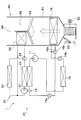
- the compressor 11 sucks, compresses and discharges the refrigerant in the refrigeration cycle apparatus 10, and corresponds to the compressor in the present disclosure.
- the compressor 11 is disposed in a vehicle bonnet.
- the compressor 11 is an electric compressor which rotationally drives, by an electric motor, a fixed displacement type compression mechanism whose discharge displacement is fixed.
- the rotation speed (that is, the refrigerant discharge capacity) of the compressor 11 is controlled by a control signal output from an air conditioning control device 60 described later.
- the outlet side of the compressor 11 is connected to the inlet side of the refrigerant passage of the high temperature side water-refrigerant heat exchanger 12.
- the high temperature side water-refrigerant heat exchanger 12 performs heat exchange between the high pressure refrigerant discharged from the compressor 11 and the high temperature side heat medium circulating in the high temperature side heat medium circuit 20 to heat the high temperature side heat medium. It is As the high temperature side heat medium, a solution containing ethylene glycol, an antifreeze liquid, etc. can be adopted.
- the high temperature side heat medium circuit 20 is a high temperature side water circuit that circulates the high temperature side heat medium.
- the water passage of the high temperature side water-refrigerant heat exchanger 12, the high temperature side heat medium pump 21, the heater core 22, the high temperature side radiator 23, the high temperature side flow rate adjustment valve 24 and the like are arranged.
- the high temperature side heat medium pump 21 is a high temperature side water pump that pumps the high temperature side heat medium to the inlet side of the water passage of the high temperature side water-refrigerant heat exchanger 12 in the high temperature side heat medium circuit 20.
- the high temperature side heat medium pump 21 is an electric pump of which the number of revolutions (that is, the water pressure feeding capacity) is controlled by a control voltage output from the air conditioning controller 60.
- the heater core 22 is disposed in a casing 51 of an indoor air conditioning unit 50 described later.
- the heater core 22 is a heat exchanger that heats the blown air by heat exchange between the high temperature side heat medium heated by the high temperature side water-refrigerant heat exchanger 12 and the blown air that has passed through the indoor evaporator 16 described later. is there.
- the heater core 22 corresponds to the heater core in the present disclosure.
- the high temperature side radiator 23 performs heat exchange between the high temperature side heat medium heated by the high temperature side water-refrigerant heat exchanger 12 and the outside air blown from the outside air fan 30, and the heat of the high temperature side heat medium is the outside air It is a heat exchanger that radiates heat.
- the high temperature side radiator 23 corresponds to the high temperature side radiator in the present disclosure.
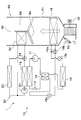
- the high temperature side radiator 23 is disposed on the front side in the vehicle bonnet. Therefore, when the vehicle is traveling, the high-temperature side radiator 23 can also be exposed to the traveling wind. As shown in FIG. 1, in the high temperature side heat medium circuit 20, the heater core 22 and the high temperature side radiator 23 are connected in parallel to the flow of the high temperature side heat medium.
- the high temperature side flow control valve 24 is constituted by an electric three-way flow control valve, and in the water passage on the outlet side of the high temperature side water-refrigerant heat exchanger 12, the heat medium inlet side of the heater core 22 and the high temperature side radiator It is arranged at the connection with the heat medium inlet side of the reference numeral 23.
- the inlet side of the high temperature side flow control valve 24 is connected to the outlet of the water passage of the high temperature side water-refrigerant heat exchanger 12.
- the heat medium inlet side of the heater core 22 is connected to one outlet of the high temperature side flow control valve 24.
- the heat medium inlet side of the high temperature side radiator 23 is connected to the other outlet of the high temperature side flow control valve 24.
- the high temperature side flow rate adjustment valve 24 flows the high temperature side heat medium flowing into the heater core 22 and the high temperature side flows into the high temperature side radiator 23.
- the high temperature side flow ratio with the flow rate of the heat medium can be adjusted continuously.
- the operation of the high temperature side flow control valve 24 is controlled by a control signal output from the air conditioning controller 60.
- the high temperature side flow rate adjustment valve 24 adjusts the high temperature side flow rate ratio
- the flow rate of the high temperature side heat medium flowing into the heater core 22 changes, and the air flow of the high temperature side heat medium in the heater core 22
- the amount of heat released to the air changes. That is, by adjusting the high temperature side flow rate ratio by the high temperature side flow rate adjustment valve 24, it is possible to adjust the heating amount of the blowing air in the heater core 22.
- a modulator 13 is connected to the outlet of the refrigerant passage of the high temperature side water-refrigerant heat exchanger 12.
- the modulator 13 is a refrigerant storage unit that separates the gas and liquid of the refrigerant flowing out of the high temperature side water-refrigerant heat exchanger 12 and stores the surplus liquid phase refrigerant.
- the modulator 13 is connected to the refrigerant inlet side of the branch portion 14a.
- the branch portion 14 a branches the flow of the high pressure refrigerant flowing out of the refrigerant passage of the high temperature side water-refrigerant heat exchanger 12 and the modulator 13.
- the branch portion 14a is formed to be a three-way joint structure having three refrigerant inlets and outlets communicating with each other, one of the three inlets and outlets being a refrigerant inlet and the remaining two being a refrigerant outlet.
- coolant inlet side of the indoor evaporator 16 is connected to one refrigerant
- coolant inlet side of the outdoor evaporator 18 is connected to the other refrigerant
- the branch 14a corresponds to the branch in the present disclosure.
- the cooling expansion valve 15a is a cooling decompression unit that decompresses the refrigerant that has flowed out from one refrigerant outlet of the branching unit 14a at least in the cooling mode and the dehumidifying and heating mode.
- the cooling expansion valve 15a corresponds to the cooling pressure reducing portion in the present disclosure.
- the cooling expansion valve 15 a also functions as a cooling flow rate adjustment unit that adjusts the flow rate of the refrigerant flowing into the indoor evaporator 16.
- the cooling expansion valve 15a is an electric variable throttle mechanism, and has a valve body and an electric actuator. That is, the cooling expansion valve 15a is configured by a so-called electric expansion valve.
- the valve body of the cooling expansion valve 15a is configured to be able to change the passage opening degree of the refrigerant passage (in other words, the throttle opening degree).
- the electric actuator has a stepping motor that changes the throttle opening of the valve body.
- the operation of the cooling expansion valve 15 a is controlled by a control signal output from the air conditioning control device 60.
- the cooling expansion valve 15a is a variable throttling mechanism having a fully open function of fully opening the refrigerant passage when the throttling degree is fully opened and a fully closing function of closing the refrigerant passage when the throttling degree is fully closed. It is configured.
- the cooling expansion valve 15a can prevent the pressure reducing action of the refrigerant from being exhibited by fully opening the refrigerant passage. Further, the cooling expansion valve 15 a can block the flow of the refrigerant into the indoor evaporator 16 by closing the refrigerant passage. That is, the cooling expansion valve 15a has both a function as a pressure reducing unit that reduces the pressure of the refrigerant and a function as a circuit switching unit that switches the refrigerant circuit.
- the refrigerant inlet side of the indoor evaporator 16 is connected to the outlet of the cooling expansion valve 15a.
- the indoor evaporator 16 is disposed in the casing 51 of the indoor air conditioning unit 50.
- the indoor evaporator 16 performs heat exchange between the low pressure refrigerant decompressed by the cooling expansion valve 15a and the blown air at least in the cooling mode and the dehumidifying heating mode to evaporate the low pressure refrigerant and cool the blown air. It is an evaporator. That is, the indoor evaporator 16 corresponds to the heat sink for cooling in the present disclosure.
- the inlet side of the evaporation pressure adjusting valve 17 is connected to the refrigerant outlet of the indoor evaporator 16.
- the evaporation pressure adjustment valve 17 is an evaporation pressure adjustment unit that maintains the refrigerant evaporation pressure in the indoor evaporator 16 at or above a predetermined reference pressure.
- the evaporation pressure control valve 17 is configured by a mechanical variable throttle mechanism that increases the valve opening degree as the refrigerant pressure on the outlet side of the indoor evaporator 16 increases.
- the evaporation pressure control valve 17 is configured to maintain the refrigerant evaporation temperature in the indoor evaporator 16 at a reference temperature (1 ° C. in the present embodiment) that can suppress the formation of frost on the indoor evaporator 16. ing.
- the outlet of the evaporating pressure adjusting valve 17 is connected to one refrigerant inlet side of the merging portion 14b.
- the merging portion 14b has a three-way joint structure similar to that of the branching portion 14a, in which two of the three inlets and outlets are used as a refrigerant inlet and the remaining one is used as a refrigerant outlet. As shown in FIG. 1, the merging portion 14 b merges the flow of the refrigerant flowing out of the evaporation pressure adjusting valve 17 and the flow of the refrigerant flowing out of the outdoor evaporator 18.
- the heat absorption expansion valve 15 b is connected to the other refrigerant flow outlet in the branch portion 14 a.
- the heat absorption expansion valve 15 b is a heat absorption decompression section that decompresses and expands the liquid phase refrigerant that has flowed out from the other refrigerant outlet in the branch section 14 a at least in the heating mode and the dehumidifying heating mode.
- the heat absorption expansion valve 15 b functions as a heating pressure reduction unit in the present disclosure.
- the heat absorption expansion valve 15 b functions as a heat absorption flow rate adjustment unit that adjusts the flow rate of the refrigerant flowing into the outdoor evaporator 18.
- the basic configuration of the heat absorption expansion valve 15b is the same as that of the cooling expansion valve 15a. That is, the heat absorption expansion valve 15b is an electric variable throttle mechanism, and has a valve body and an electric actuator. Then, the heat absorption expansion valve 15b has a full open function and a full close function, as with the cooling expansion valve 15a.
- the heat absorption expansion valve 15b can prevent the depressurizing action of the refrigerant from being exhibited by fully opening the refrigerant passage, and blocking the flow of the refrigerant to the outdoor evaporator 18 by closing the refrigerant passage.
- the heat absorption expansion valve 15b has both a function as a pressure reducing unit that reduces the pressure of the refrigerant and a function as a circuit switching unit that switches the refrigerant circuit.
- the refrigerant inlet side of the outdoor evaporator 18 is connected to the outlet of the heat absorption expansion valve 15b.
- the outdoor evaporator 18 exchanges heat between the low pressure refrigerant decompressed by the heat absorption expansion valve 15b and the outside air blown from the outside air fan 30 in at least the heating mode and the dehumidifying heating mode, and evaporates the low pressure refrigerant to make the refrigerant It is an endothermic evaporator that exerts an endothermic effect.
- the outdoor evaporator 18 functions as a heating heat sink in the present disclosure, and the outside air functions as a heat source fluid.
- the outdoor evaporator 18 is disposed on the front side in the vehicle bonnet.
- the other refrigerant inlet side of the merging portion 14 b is connected to the refrigerant outlet of the outdoor evaporator 18.
- the suction port side of the compressor 11 is connected to the refrigerant
- the indoor air conditioning unit 50 which comprises the vehicle air conditioner 1 is demonstrated.
- the indoor air conditioning unit 50 forms an air passage for blowing out the blowing air whose temperature has been adjusted by the refrigeration cycle apparatus 10 to an appropriate place in the vehicle compartment in the vehicle air conditioner 1.
- the indoor air conditioning unit 50 is disposed inside the instrument panel (i.e., instrument panel) at the foremost part of the passenger compartment.
- the indoor air conditioning unit 50 is configured by housing a blower 52, an indoor evaporator 16, a heater core 22 and the like in an air passage formed inside a casing 51 forming the outer shell thereof.
- the casing 51 forms an air passage for blowing air blown into the vehicle compartment, and is molded of a resin (specifically, polypropylene) which has a certain degree of elasticity and is excellent in strength.
- an internal / external air switching device 53 is disposed on the most upstream side of the flow of the blown air of the casing 51.
- the inside / outside air switching device 53 switches and introduces inside air (air in the vehicle interior) and outside air (air outside the vehicle) into the casing 51.
- the inside / outside air switching device 53 continuously adjusts the opening area of the inside air introduction port for introducing inside air into the casing 51 and the outside air introduction port for introducing outside air by means of the inside / outside air switching door.
- the introduction rate with the introduction air volume can be changed.
- the inside and outside air switching door is driven by an electric actuator for the inside and outside air switching door. The operation of the electric actuator is controlled by a control signal output from the air conditioning controller 60.
- a blower 52 is disposed downstream of the inside / outside air switching device 53 in the flow of the blown air.
- the blower 52 is constituted by an electric blower which drives a centrifugal multi-blade fan by an electric motor, and functions to blow air taken in via the inside / outside air switching device 53 toward the vehicle interior for blowing.
- the blowing air blown by the blower 52 corresponds to the heat exchange target fluid in the present disclosure.
- the rotation speed (that is, the blowing capacity) of the blower 52 is controlled by the control voltage output from the air conditioning control device 60.
- the indoor evaporator 16 and the heater core 22 are arranged in this order with respect to the flow of the blown air on the downstream side of the blown air flow of the blower 52. That is, the indoor evaporator 16 is disposed upstream of the heater core 22 in the flow of the blown air.
- a cold air bypass passage 55 is formed, in which the blown air having passed through the indoor evaporator 16 is allowed to bypass the heater core 22 and flow downstream.
- An air mix door 54 is disposed on the downstream side of the air flow of the indoor evaporator 16 and on the upstream side of the air flow of the heater core 22.
- the air mix door 54 adjusts the air volume ratio of the air volume passing through the heater core 22 and the air volume passing through the cold air bypass passage 55 in the blown air after passing through the indoor evaporator 16.
- the air mix door 54 is driven by an electric actuator for driving the air mix door.
- the operation of the electric actuator is controlled by a control signal output from the air conditioning controller 60.
- a mixing space 56 for mixing the air heated by the heater core 22 and the air not passing through the cold air bypass passage 55 and not heated by the heater core 22.
- an opening for blowing out the air (air-conditioned air) mixed in the mixing space into the vehicle compartment is disposed.
- the face opening hole is an opening hole for blowing the conditioned air toward the upper body of the occupant in the vehicle compartment.
- the foot opening hole is an opening hole for blowing the conditioned air toward the feet of the occupant.
- the defroster opening hole is an opening hole for blowing the conditioned air toward the inner side surface of the vehicle front windshield.
- face opening holes, foot opening holes, and defroster opening holes are respectively provided in the passenger compartment via a duct that forms an air passage, face outlet, foot outlet, and defroster outlet (all not shown) )It is connected to the.
- the temperature of the conditioned air mixed in the mixing space is adjusted by adjusting the air volume ratio of the air volume passing the heater core 22 and the air volume passing the cold air bypass passage 55 by the air mix door 54.
- the temperature of the air (air-conditioned air) blown out from the outlets into the vehicle compartment is also adjusted.
- a defroster door (not shown) is arranged to adjust the opening area of the hole.
- These face door, foot door, and defroster door constitute an air outlet mode switching device that switches the air outlet from which the conditioned air is blown out.
- the face door, the foot door, and the defroster door are connected to an electric actuator for driving the air outlet mode door via a link mechanism and the like, and are operated to rotate in conjunction with each other.
- the operation of the electric actuator is controlled by a control signal output from the air conditioning controller 60.
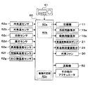
- the air conditioning control device 60 is configured of a known microcomputer including a CPU, a ROM, a RAM, and the like, and peripheral circuits thereof.
- the air-conditioning control apparatus 60 performs various calculations and processing based on the air-conditioning control program memorize
- the control target devices in the first embodiment include the compressor 11, the cooling expansion valve 15a, the heat absorption expansion valve 15b, the high temperature side heat medium pump 21, the high temperature side flow control valve 24, and the outside air fan 30. , The blower 52 and the like are included.
- an inside air temperature sensor 62a As shown in FIG. 2, on the input side of the air conditioning controller 60, an inside air temperature sensor 62a, an outside air temperature sensor 62b, a solar radiation sensor 62c, a high pressure sensor 62d, an evaporator temperature sensor 62e, an air conditioning air temperature sensor 62f, an outlet side temperature A sensor group for air conditioning control such as the sensor 62g is connected.
- the air conditioning control device 60 receives detection signals of these air conditioning control sensors.
- the inside air temperature sensor 62a is an inside air temperature detection unit that detects a vehicle room temperature (inside air temperature) Tr.
- the outside air temperature sensor 62b is an outside air temperature detection unit that detects the temperature outside the vehicle (outside air temperature) Tam.
- the solar radiation sensor 62c is a solar radiation amount detection unit that detects the solar radiation amount As emitted to the vehicle interior.
- the high pressure sensor 62 d is a refrigerant pressure detection unit that detects the high pressure refrigerant pressure Pd of the refrigerant flow path from the discharge port side of the compressor 11 to the inlet side of the cooling expansion valve 15 a or the heat absorption expansion valve 15 b.
- the evaporator temperature sensor 62 e is an evaporator temperature detection unit that detects a refrigerant evaporation temperature (evaporator temperature) Tefin in the indoor evaporator 16.
- the air conditioning air temperature sensor 62f is an air conditioning air temperature detection unit that detects the temperature of the air that is blown into the vehicle compartment.
- the outlet-side temperature sensor 62 g is an outlet-side temperature detection unit that detects the outlet-side temperature Te of the refrigerant on the outlet side of the outdoor evaporator 18.
- an operation panel 61 disposed in the vicinity of the instrument panel at the front of the vehicle interior is connected. Accordingly, operation signals from various operation switches provided on the operation panel 61 are input to the air conditioning control device 60.
- an auto switch for setting or canceling the automatic control operation of the vehicle air conditioner 1
- a cooling switch for requesting cooling of the vehicle interior
- a blower 52 There are an air volume setting switch for manually setting the air volume, a temperature setting switch for setting the target temperature Tset in the vehicle interior, and the like.
- control unit for controlling various control target devices connected to the output side is integrally configured, but the configuration for controlling the operation of each control target device (hardware and software ) Constitute a control unit that controls the operation of each control target device.
- the configuration that controls the operation of the compressor 11 is the discharge capacity control unit 60a.
- a circuit switching control unit 60b controls the operation of the cooling expansion valve 15a and the heat absorption expansion valve 15b as a circuit switching unit.
- the structure for determining the danger of the frost formation in the outdoor evaporator 18, etc. among the air-conditioning control apparatuses 60 is the frosting determination part 60c.
- the frost formation determining unit 60c is implemented by a control program for determination that is executed at predetermined intervals as a subroutine of the air conditioning control program. Specifically, when the outlet side temperature Te detected by the outlet side temperature sensor 62g is lower than a value obtained by subtracting a predetermined reference temperature ⁇ from the outside air temperature Tam detected by the outside air temperature sensor, The frost determination unit 60 c determines that there is a risk of frost formation in the outdoor evaporator 18.
- the operation mode can be appropriately switched from the plurality of operation modes.
- the switching of these operation modes is performed by executing the air conditioning control program stored in advance in the air conditioning control device 60.
- the target blowout temperature TAO of the air to be blown into the vehicle compartment is calculated. calculate. Then, the operation mode is switched based on the target blowout temperature TAO and the detection signal.
- the operation in the cooling mode and the operation in the heating mode will be described below.
- the cooling mode is an operation mode in which the blowing air, which is a heat exchange target fluid, is cooled and blown into the vehicle compartment, and is an example of the cooling mode in the present disclosure.
- the air conditioning control device 60 opens the cooling expansion valve 15a at a predetermined throttle opening degree, and brings the heat absorption expansion valve 15b into a fully closed state.
- the compressor 11 high temperature side water-refrigerant heat exchanger 12 ⁇ modulator 13 ⁇ branching portion 14a ⁇ cooling expansion valve 15a ⁇ indoor evaporator 16 ⁇ evaporation pressure control valve 17 ⁇ merge
- a vapor compression type refrigeration cycle in which the refrigerant circulates in the order of the part 14 b ⁇ the compressor 11 is configured.
- the refrigerant in the cooling mode, the refrigerant is made to flow into the indoor evaporator 16, and the refrigerant circuit is switched to the refrigerant circuit for cooling the blowing air by heat exchange with the blowing air.
- the air conditioning control device 60 controls the operation of various control target devices connected to the output side.
- the air conditioning control device 60 controls the operation of the compressor 11 such that the refrigerant evaporation temperature Tefin detected by the evaporator temperature sensor 62e becomes the target evaporation temperature TEO.
- the target evaporation temperature TEO is determined based on the target blowing temperature TAO with reference to the control map for the cooling mode stored in advance in the air conditioning control device 60.
- the target evaporation temperature TEO is raised along with the rise of the target blowout temperature TAO so that the blown air temperature TAV detected by the air conditioning air temperature sensor 62f approaches the target blowout temperature TAO. Furthermore, the target evaporation temperature TEO is determined to be a value in a range (specifically, 1 ° C. or more) in which frost formation of the indoor evaporator 16 can be suppressed.
- the air conditioning control device 60 operates the high temperature side heat medium pump 21 so as to exert the water pressure transfer capability in the cooling mode determined in advance. Further, the air conditioning control device 60 operates the high temperature side flow control valve 24 so that the total flow rate of the high temperature side heat medium flowing out from the water passage of the high temperature side water-refrigerant heat exchanger 12 flows into the high temperature side radiator 23 Control.
- the air conditioning control device 60 determines the control voltage (blowing capacity) of the blower 52 with reference to the control map stored in advance in the air conditioning control device 60 based on the target blowing temperature TAO. Specifically, in this control map, the air flow of the blower 52 is maximized in the extremely low temperature region (maximum cooling region) and the extremely high temperature region (maximum heating region) of the target blowing temperature TAO, and as the intermediate temperature region is approached. Reduce air flow.
- the air conditioning control device 60 controls the operation of the air mix door 54 so that the cold air bypass passage 55 is fully opened and the air passage on the heater core 22 side is closed.
- the air-conditioning control device 60 appropriately controls the operation of the other various control target devices.
- the high pressure refrigerant discharged from the compressor 11 flows into the high temperature side water-refrigerant heat exchanger 12.
- the high temperature side heat medium pump 21 since the high temperature side heat medium pump 21 operates, the high pressure refrigerant and the high temperature side heat medium exchange heat, the high pressure refrigerant is cooled and condensed, and the high temperature side heat medium Is heated.
- the high temperature side heat medium heated by the high temperature side water-refrigerant heat exchanger 12 flows into the high temperature side radiator 23 through the high temperature side flow rate adjustment valve 24.
- the high temperature side heat medium flowing into the high temperature side radiator 23 exchanges heat with the outside air and radiates heat. Thereby, the high temperature side heat medium is cooled.
- the high temperature side heat medium cooled by the high temperature side radiator 23 is drawn into the high temperature side heat medium pump 21 and is pressure-fed again to the water passage of the high temperature side water-refrigerant heat exchanger 12.
- the throttle opening degree of the cooling expansion valve 15a is adjusted so that the degree of superheat of the refrigerant on the outlet side of the indoor evaporator 16 is approximately 3 ° C.
- the low pressure refrigerant reduced in pressure by the cooling expansion valve 15 a flows into the indoor evaporator 16.
- the refrigerant flowing into the indoor evaporator 16 absorbs heat from the air blown from the fan 52 and evaporates. Thereby, the blowing air which is a heat exchange object fluid is cooled.
- the refrigerant flowing out of the indoor evaporator 16 is sucked into the compressor 11 via the evaporation pressure adjusting valve 17 and the merging portion 14 b and compressed again.
- the blowing air cooled by the indoor evaporator 16 can be blown into the vehicle compartment to perform cooling of the vehicle compartment.
- the heating mode is an operation mode in which the outdoor evaporator 18 absorbs heat from the outside air, which is the heat source fluid, and heats the blowing air, which is the heat exchange target fluid, to blow the air into the vehicle compartment. It is an example of a heating mode.
- the air conditioning control device 60 fully closes the cooling expansion valve 15a and opens the heat absorption expansion valve 15b at a predetermined throttle opening degree.
- the compressor 11 high temperature side water-refrigerant heat exchanger 12 ⁇ the modulator 13 ⁇ the branch portion 14a ⁇ the heat absorption expansion valve 15b ⁇ the outdoor evaporator 18 ⁇ the merging portion 14b ⁇ the compressor 11
- a vapor compression type refrigeration cycle in which the refrigerant circulates is configured.
- the refrigerant in the heating mode, the refrigerant is caused to flow into the outdoor evaporator 18, and switching to a refrigerant circuit that heats the blowing air is performed using heat absorbed by heat exchange with the outside air.
- the air conditioning control device 60 controls the operation of various control target devices connected to the output side.
- the air-conditioning control device 60 controls the operation of the compressor 11 such that the high-pressure refrigerant pressure Pd detected by the high-pressure sensor 62d becomes the target high-pressure PCO.
- the target high pressure PCO is determined based on the target blowout temperature TAO with reference to the control map for the heating mode stored in advance in the air conditioning control device 60.
- the target high pressure PCO is raised with the rise of the target blowing temperature TAO so that the blowing air temperature TAV approaches the target blowing temperature TAO.
- the air conditioning control device 60 operates the high temperature side heat medium pump 21 so as to exert the water pressure transfer capability in the predetermined heating mode.
- the air conditioning controller 60 controls the operation of the high temperature side flow control valve 24 so that the total flow rate of the high temperature side heat medium flowing out of the water passage of the high temperature side water-refrigerant heat exchanger 12 flows into the heater core 22.
- the air-conditioning control apparatus 60 determines the control voltage (blower capability) of the air blower 52 similarly to air conditioning mode. Further, the air conditioning control device 60 controls the operation of the air mix door 54 so as to fully open the air passage on the heater core 22 side and close the cold air bypass passage 55. The air conditioning control device 60 appropriately controls the operation of various other control target devices.
- the high pressure refrigerant discharged from the compressor 11 flows into the high temperature side water-refrigerant heat exchanger 12.
- the high temperature side heat medium pump 21 since the high temperature side heat medium pump 21 operates, the high pressure refrigerant and the high temperature side heat medium exchange heat, the high pressure refrigerant is cooled and condensed, and the high temperature side heat medium Is heated.
- the high temperature side heat medium heated by the high temperature side water-refrigerant heat exchanger 12 flows into the heater core 22 via the high temperature side flow rate adjustment valve 24.
- the high temperature side heat medium having flowed into the heater core 22 exchanges heat with the air that has passed through the indoor evaporator 16 and radiates heat since the air mix door 54 fully opens the air passage on the heater core 22 side.
- blowing air which is a heat exchange object fluid is heated, and the temperature of blowing air approaches the target blowing temperature TAO.
- the high temperature side heat medium flowing out of the heater core 22 is sucked into the high temperature side heat medium pump 21 and is pressure-fed again to the water passage of the high temperature side water-refrigerant heat exchanger 12.
- the throttle opening degree of the heat absorption expansion valve 15b is adjusted so that the refrigerant on the outlet side of the outdoor evaporator 18 is in a gas-liquid two-phase state.
- the low pressure refrigerant reduced in pressure by the heat absorption expansion valve 15 b flows into the outdoor evaporator 18.
- the refrigerant flowing into the outdoor evaporator 18 absorbs heat from the outside air, which is a heat source fluid blown from the outside air fan 30, and evaporates.
- the refrigerant flowing out of the outdoor evaporator 18 is sucked into the compressor 11 via the merging portion 14b and compressed again.
- heating of the vehicle interior can be performed by heating the blown air, which is the fluid to be heat-exchanged, with the heater core 22 and blowing it out into the vehicle interior.
- (C) Dehumidifying and heating mode In the dehumidifying and heating mode, the air which is the heat exchange target fluid cooled by the indoor evaporator 16 is heated by heat absorbed from the outside air which is the heat source fluid by the outdoor evaporator 18 It is an operation mode which blows air indoors, and is an example of a heating mode in this indication.
- the air conditioning control device 60 opens the cooling expansion valve 15a and the heat absorption expansion valve 15b at a predetermined opening degree.
- the refrigerant flows from the compressor 11 ⁇ high temperature side water-refrigerant heat exchanger 12 ⁇ modulator 13 ⁇ branch portion 14a, and one side of the branch portion 14a ⁇ cooling expansion valve 15a ⁇ indoor evaporation It flows to the vessel 16 and flows from the other side of the branch portion 14 a to the heat absorption expansion valve 15 b to the outdoor evaporator 18.
- the refrigerant flowing out of the indoor evaporator 16 and the refrigerant flowing out of the outdoor evaporator 18 merge at the merging portion 14b, and then flow and circulate in the order of the compressor 11. That is, in the dehumidifying and heating mode, a vapor compression type refrigeration cycle in which the refrigerant flows in parallel to the indoor evaporator 16 and the outdoor evaporator 18 is configured.
- the air conditioning control device 60 controls the operation of various control target devices connected to the output side with reference to the control map for the dehumidifying heating mode and the like stored in advance in the air conditioning control device 60. .
- the high pressure refrigerant discharged from the compressor 11 flows into the high temperature side water-refrigerant heat exchanger 12.
- the high temperature side heat medium pump 21 since the high temperature side heat medium pump 21 operates, the high pressure refrigerant and the high temperature side heat medium exchange heat, the high pressure refrigerant is cooled and condensed, and the high temperature side heat medium Is heated.
- the high temperature side heat medium heated by the high temperature side water-refrigerant heat exchanger 12 flows into the heater core 22 via the high temperature side flow rate adjustment valve 24.
- the high temperature side heat medium that has flowed into the heater core 22 exchanges heat with the blowing air cooled by the indoor evaporator 16 and radiates heat since the air mixing door 54 fully opens the air passage on the heater core 22 side.
- the blowing air which is the heat exchange target fluid
- the temperature of the blowing air approaches the target blowing temperature TAO.
- the high temperature side heat medium flowing out of the heater core 22 is sucked into the high temperature side heat medium pump 21 and is pressure-fed again to the water passage of the high temperature side water-refrigerant heat exchanger 12.
- the throttle opening degree of the cooling expansion valve 15a is adjusted so that the degree of superheat of the refrigerant on the outlet side of the indoor evaporator 16 is approximately 3 ° C.
- the low pressure refrigerant reduced in pressure by the cooling expansion valve 15 a flows into the indoor evaporator 16.
- the refrigerant flowing into the indoor evaporator 16 absorbs heat from the air blown from the fan 52 and evaporates. Thereby, the blowing air which is a heat exchange object fluid is cooled.
- the refrigerant flowing out of the indoor evaporator 16 is sucked into the compressor 11 via the evaporation pressure adjusting valve 17 and the merging portion 14 b and compressed again.
- the high pressure refrigerant branched at the branch portion 14a flows into the heat absorption expansion valve 15b and is decompressed.
- the throttle opening degree of the heat absorption expansion valve 15b is adjusted so that the refrigerant on the outlet side of the outdoor evaporator 18 is in a gas-liquid two-phase state.
- the low pressure refrigerant reduced in pressure by the heat absorption expansion valve 15 b flows into the outdoor evaporator 18.
- the refrigerant flowing into the outdoor evaporator 18 absorbs heat from the outside air, which is a heat source fluid blown from the outside air fan 30, and evaporates.
- the refrigerant that has flowed out of the outdoor evaporator 18 merges with the refrigerant that has passed through the indoor evaporator 16 and the evaporation pressure adjusting valve 17 at the merging portion 14b, and is drawn into the compressor 11 and compressed again.
- the heater core 22 is disposed on the downstream side of the air flow of the indoor evaporator 16 inside the casing 51. Therefore, in the dehumidifying and heating mode, the air cooled by the indoor evaporator 16 is evaporated outside the room. The heat absorbed by the vessel 18 can be used to heat the heater core 22.
- the refrigeration cycle apparatus 10 switches the refrigerant circuit to select the cooling mode, the heating mode, and the dehumidifying heating mode among the plurality of operation modes. It can be switched, and comfortable air conditioning of the vehicle interior can be realized.
- the cycle configuration tends to be complicated.
- the refrigeration cycle apparatus 10 according to the first embodiment there is no switching between the refrigerant circuit that causes the high pressure refrigerant to flow into the same heat exchanger and the refrigerant circuit that causes the low pressure refrigerant to flow.
- the refrigerant circuit can be switched with a simple configuration without causing complication of the cycle configuration. .
- the refrigerant evaporation temperature in the outdoor evaporator 18 may be lower than the outside air temperature. For this reason, in the heating mode or the like, frost may occur on the outdoor evaporator 18. When frost formation occurs, the heat exchange performance of the outdoor evaporator 18 is reduced, and thus the heating performance of the vehicle air conditioner 1 is reduced.
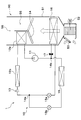
- the configuration shown in FIG. 3 is adopted, and part of the heat radiated on the cycle high pressure side It utilizes and the suppression and the defrost of frost in the outdoor evaporator 18 are implement
- the heat exchange portion of the outdoor evaporator 18 is a heat exchange portion of the high temperature side radiator 23 in the high temperature side heat medium circuit 20 by the plurality of heat transfer fins 31 having thermal conductivity. Connected to.
- the heat transfer fins 31 are formed by sharing a part of the outdoor evaporator 18 or a part of the high temperature side radiator 23 (for example, heat exchange fins), and are formed using a heat transferable metal. ing.
- the heat transfer fins 31 correspond to the heat transfer members in the present disclosure.
- the outdoor evaporator 18 and the high temperature side radiator 23 are thermally connected by a plurality of heat transfer fins 31 and configured to be able to transmit the heat radiated by the high temperature side radiator 23 to the outdoor evaporator 18 ing.
- the heat transfer member in the present disclosure is not limited to the heat transfer fins 31 configured by sharing heat exchange fins.
- various configurations can be adopted as long as heat can be transferred from the high temperature side radiator 23 to the outdoor evaporator 18, and the components of the outdoor evaporator 18 and the high temperature side radiator 23 It is also possible to use separate members having thermal conductivity instead of being common.
- the heat radiated by the high temperature side radiator 23 can be transmitted to the outdoor evaporator 18 which is the low temperature side.
- the heating mode, the dehumidifying heating mode, etc. are executed, the progress of frost formation in the outdoor evaporator 18 is suppressed, or the outdoor evaporator 18 is defrosted.
- the flow rate of the high temperature side heat medium is increased to the high temperature side radiator 23 side rather than the heater core 22 side.
- more heat is transferred from the high temperature side radiator 23 to the outdoor evaporator 18 through the heat transfer fins 31, so that the outdoor evaporator 18 can be defrosted quickly.
- the flow rate of the high temperature side heat medium is controlled to be smaller toward the high temperature side radiator 23 than the heater core 22 side. Therefore, the frost formation of the outdoor evaporator 18 can be suppressed, maintaining the heating capability of the blowing air by the heater core 22 as much as possible.
- the refrigerant circuit on the indoor evaporator 16 side connected to the branch unit 14a by the circuit switching control unit 60b, and the outdoor evaporator 18 side can be switched.
- the refrigerant reduced in pressure by the cooling expansion valve 15a is subjected to heat exchange in the indoor evaporator 16, and the heat exchange target fluid is used. Some blast air can be cooled.
- the refrigerant reduced in pressure by the heat absorption expansion valve 15b is subjected to heat exchange between the outdoor air as the heat source fluid and the refrigerant in the outdoor evaporator 18. By doing this, it is possible to heat the blown air using the outside air as a heat source.
- the refrigerant depressurized by the heat absorption expansion valve 15b is heated by the outdoor evaporator 18 to heat the outside air as the heat source fluid and the refrigerant.
- the blowing air cooled by the indoor evaporator 16 can be heated using the outside air as a heat source.
- the refrigeration cycle apparatus 10 even when switching to any of the refrigerant circuits, it is not necessary to flow the high pressure refrigerant into the indoor evaporator 16 and the outdoor evaporator 18, resulting in complication of the cycle configuration.
- the refrigerant circuit can be switched with a simple configuration. That is, the refrigeration cycle apparatus 10 can realize a plurality of operation modes including the cooling mode, the heating mode, and the dehumidifying and heating mode without causing complication of the cycle configuration.
- the heat absorbed by the indoor evaporator 16 is dissipated to the outside air by the high temperature side radiator 23 of the high temperature side heat medium circuit 20 constituting the heating unit. That is, the outdoor evaporator 18 does not function as a radiator but functions as a heat absorber. In other words, in the cooling mode of the refrigeration cycle apparatus 10, the high-pressure refrigerant does not flow into the outdoor evaporator 18.
- the refrigeration cycle apparatus 10 includes the high temperature side water-refrigerant heat exchanger 12, and the heater core 22 is disposed in the high temperature side heat medium circuit 20 for circulating the high temperature side heat medium. Therefore, in the heating mode or the like, the high temperature side heat medium heated by the high temperature side water-refrigerant heat exchanger 12 can be caused to flow into the heater core 22 to heat the blowing air.
- the high temperature side radiator 23 is disposed in the high temperature side heat medium circuit 20. Accordingly, the heat absorbed by the indoor evaporator 16 and the outdoor evaporator 18 can be dissipated to the outside air, and cooling of the vehicle interior can be appropriately performed in the cooling mode.
- the outdoor evaporator 18 and the high temperature side radiator 23 are thermally connected, and the heat which the high temperature side heat medium in the high temperature side heat medium circuit 20 has is transmitted to the outdoor evaporator 18 it can.
- the heat exchange portion of the outdoor evaporator 18 and the heat exchange portion of the high temperature side radiator 23 are connected by a plurality of heat transfer fins 31.
- the heat radiated by the high temperature side radiator 23 can be transmitted to the outdoor evaporator 18 through the plurality of heat transfer fins 31, so that the progress of frost formation in the outdoor evaporator 18 can be suppressed, or the outdoor Defrosting of the evaporator 18 can be performed.
- the refrigeration cycle apparatus 10 is applied to the air conditioner 1 for a vehicle mounted on an electric vehicle, and is a blown air blown into a vehicle compartment which is a space to be air conditioned. Perform the function of adjusting the temperature of the
- the vehicle air conditioner 1 includes the refrigeration cycle apparatus 10, the high temperature side heat medium circuit 20, and the indoor air conditioning unit 50 as in the first embodiment. Is configured.
- the configurations of the high temperature side heat medium circuit 20 and the indoor air conditioning unit 50 in the second embodiment are the same as in the first embodiment. Therefore, the description about these is omitted.
- the high temperature side heat medium circuit 20 including the high temperature side water-refrigerant heat exchanger 12 functions as the heating unit of the present disclosure.
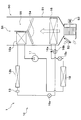
- the arrangement of the cooling expansion valve 15a, the heat absorption expansion valve 15b, the indoor evaporator 16, and the outdoor evaporator 18 is different from that of the first embodiment described above. That is, also in the second embodiment, the inlet side of the refrigerant passage of the high temperature side water-refrigerant heat exchanger 12 is connected to the discharge port of the compressor 11, and the refrigerant outlet of the high temperature side water-refrigerant heat exchanger 12 The modulator 13 is connected to the side.
- the modulator 13 is connected to a cooling expansion valve 15 a.
- the cooling expansion valve 15 a is an electric expansion valve, and is a cooling pressure reducing unit that reduces the pressure of the refrigerant flowing out of the high temperature side water-refrigerant heat exchanger 12.
- the cooling expansion valve 15a has a fully open function and a fully closed function, and functions as a pressure reducing section that reduces the pressure of the refrigerant and as a circuit switching section that switches the refrigerant circuit. And have.
- the refrigerant inlet side of the indoor evaporator 16 is connected to the outlet of the cooling expansion valve 15a.
- the indoor evaporator 16 is disposed inside the casing 51 of the indoor air conditioning unit 50, and is a cooling evaporator that exchanges heat between the low pressure refrigerant and the blowing air to evaporate the low pressure refrigerant and cool the blowing air. That is, the indoor evaporator 16 corresponds to the heat sink for cooling in the present disclosure.
- an endothermic expansion valve 15 b is connected to the refrigerant outlet of the indoor evaporator 16.
- the heat absorption expansion valve 15 b is an electric expansion valve, and is a heating pressure reduction unit that reduces the pressure of the refrigerant flowing out of the indoor evaporator 16.
- the heat absorption expansion valve 15b has a fully open function and a fully closed function, and functions as a pressure reducing section that reduces the pressure of the refrigerant and as a circuit switching section that switches the refrigerant circuit. And have.
- a three-way valve 16 b is disposed between the outlet of the cooling expansion valve 15 a and the refrigerant inlet side of the indoor evaporator 16.
- a bypass passage 16a is connected to one outlet of the three-way valve 16b.
- the other end side of the bypass flow passage 16 a is connected between the refrigerant outlet side of the indoor evaporator 16 and the inlet of the heat absorption expansion valve 15 b.
- the three-way valve 16 b functions as a circuit switching unit in the present disclosure.
- the refrigerant inlet side of the outdoor evaporator 18 is connected to the outlet of the heat absorption expansion valve 15b.
- the outdoor evaporator 18 exchanges heat between the low pressure refrigerant decompressed by the heat absorption expansion valve 15b and the outside air blown from the outside air fan 30 in the dehumidifying and heating mode etc., evaporates the low pressure refrigerant and absorbs heat to the refrigerant. It is an endothermic evaporator that exerts That is, the outdoor evaporator 18 functions as a heat sink for heating in the present disclosure, and the outside air functions as a heat source fluid.
- the suction port side of the compressor 11 is connected to the refrigerant outlet side of the outdoor evaporator 18. That is, in the refrigeration cycle apparatus 10 according to the second embodiment, the indoor evaporator 16 and the outdoor evaporator 18 are connected in series.
- the control system of the vehicle air conditioner 1 according to the second embodiment is basically the same as that of the first embodiment, and thus the description thereof will be omitted.
- the vehicle air conditioner 1 according to the second embodiment can appropriately switch the operation mode from a plurality of operation modes. Similar to the first embodiment, these operation modes are switched by executing an air conditioning control program stored in advance in the air conditioning control device 60. Among the plurality of operation modes, the operation in the cooling mode, the operation in the heating mode, and the operation in the dehumidifying heating mode will be described below.
- the cooling mode is an operation mode for cooling the air, which is the fluid to be heat-exchanged, and blowing it into the vehicle compartment, and is an example of the cooling mode in the present disclosure.
- the air conditioning control device 60 opens the cooling expansion valve 15a at a predetermined throttle opening degree, and brings the heat absorption expansion valve 15b into a fully open state.
- the three-way valve 16b is controlled to close the bypass flow passage 16a.
- the refrigerant flowing out of the cooling expansion valve 15 a flows into the indoor evaporator 16.
- the compressor 11 in the refrigeration cycle apparatus 10 in the cooling mode, the compressor 11 ⁇ high temperature side water-refrigerant heat exchanger 12 ⁇ modulator 13 ⁇ cooling expansion valve 15a ⁇ three-way valve 16b ⁇ indoor evaporator 16 ⁇ heat absorption expansion valve 15b ⁇ outdoor
- a vapor compression refrigeration cycle in which the refrigerant circulates in the order of the evaporator 18 ⁇ the compressor 11 is configured.
- the refrigerant in the cooling mode, the refrigerant is made to flow into the indoor evaporator 16, and the refrigerant circuit is switched to a refrigerant circuit intended to cool the blowing air by heat exchange with the blowing air.
- the air conditioning control device 60 controls the operation of various control target devices connected to the output side based on the target blowout temperature TAO and the detection signal of the sensor group.
- the air conditioning control device 60 operates the high temperature side heat medium pump 21 so as to exert the water pressure transfer capability in the predetermined cooling mode.
- the air conditioning control device 60 operates the high temperature side flow control valve 24 so that the total flow rate of the high temperature side heat medium flowing out from the water passage of the high temperature side water-refrigerant heat exchanger 12 flows into the high temperature side radiator 23 Control.
- the air conditioning control device 60 determines the control voltage (blowing capacity) of the blower 52 with reference to the control map stored in advance in the air conditioning control device 60 based on the target blowing temperature TAO. Further, the air conditioning control device 60 controls the operation of the air mix door 54 so that the cold air bypass passage 55 is fully opened and the air passage on the heater core 22 side is closed. The air-conditioning control device 60 appropriately controls the operation of the other various control target devices.
- the high pressure refrigerant discharged from the compressor 11 flows into the high temperature side water-refrigerant heat exchanger 12.
- the high temperature side heat medium pump 21 since the high temperature side heat medium pump 21 operates, the high pressure refrigerant and the high temperature side heat medium exchange heat, the high pressure refrigerant is cooled and condensed, and the high temperature side heat medium Is heated.
- the high temperature side heat medium heated by the high temperature side water-refrigerant heat exchanger 12 flows into the high temperature side radiator 23 through the high temperature side flow rate adjustment valve 24.
- the high temperature side heat medium flowing into the high temperature side radiator 23 exchanges heat with the outside air and radiates heat. Thereby, the high temperature side heat medium is cooled.
- the high temperature side heat medium cooled by the high temperature side radiator 23 is drawn into the high temperature side heat medium pump 21 and is pressure-fed again to the water passage of the high temperature side water-refrigerant heat exchanger 12.
- the throttle opening degree of the cooling expansion valve 15a is adjusted so that the degree of superheat of the refrigerant on the outlet side of the indoor evaporator 16 is approximately 3 ° C.
- the low pressure refrigerant reduced in pressure by the cooling expansion valve 15 a flows into the indoor evaporator 16.
- the refrigerant flowing into the indoor evaporator 16 absorbs heat from the air blown from the fan 52 and evaporates. Thereby, the blowing air which is a heat exchange object fluid is cooled.
- the refrigerant flowing out of the indoor evaporator 16 flows into the outdoor evaporator 18 without being reduced in pressure by the heat absorption expansion valve 15 b, and is sucked into the compressor 11 again with almost no heat exchange in the outdoor evaporator 18. It is compressed.
- cooling of the vehicle interior can be performed by blowing the blown air cooled by the indoor evaporator 16 into the vehicle interior.
- (B) Heating mode In the heating mode in the second embodiment, the air which is the heat exchange fluid is heated by the outdoor evaporator 18 using the heat absorbed from the outside air which is the heat source fluid and blown into the vehicle interior Operation mode, which is an example of the heating mode in the present disclosure.
- the air conditioning control device 60 In the heating mode, the air conditioning control device 60 fully opens the cooling expansion valve 15a and opens the heat absorption expansion valve 15b at a predetermined throttle opening degree. At this time, the three-way valve 16b is controlled to fully open the bypass flow passage 16a. As a result, the refrigerant that has passed through the cooling expansion valve 15a flows into the heat absorption expansion valve 15b via the bypass flow path 16a without flowing into the indoor evaporator 16.
- the compressor 11 in the refrigeration cycle apparatus 10 in the heating mode, the compressor 11 ⁇ high temperature side water-refrigerant heat exchanger 12 ⁇ modulator 13 ⁇ three-way valve 16 b ⁇ bypass flow path 16 a ⁇ heat absorption expansion valve 15 b ⁇ outdoor evaporator 18 ⁇ compressor
- a vapor compression refrigeration cycle in which the refrigerant circulates in the order of 11 is configured. That is, in the heating mode, the refrigerant circuit is switched to a refrigerant circuit aiming to heat the blown air by using the heat absorbed by the outdoor evaporator 18.
- the air conditioning control device 60 controls the operation of various control target devices connected to the output side based on the target blowout temperature TAO and the detection signal of the sensor group.
- the throttle opening degree of the heat absorption expansion valve 15b is determined based on the target blowout temperature TAO or the like with reference to the control map regarding the heating mode.
- the air conditioning control device 60 operates the high temperature side heat medium pump 21 so as to exert the water pressure transfer capability in the predetermined heating mode.
- the air conditioning controller 60 controls the operation of the high temperature side flow control valve 24 so that the high temperature side heat medium flowing out of the water passage of the high temperature side water-refrigerant heat exchanger 12 flows into the heater core 22 side.
- the control signal output to the servo motor of the air mix door 54 is completely opened by the air mix door 54 when the air mix door 54 fully opens the air passage on the heater core 22 side. It is determined to pass through the air passage on the heater core 22 side.
- the high pressure refrigerant discharged from the compressor 11 flows into the high temperature side water-refrigerant heat exchanger 12.
- the high temperature side heat medium pump 21 since the high temperature side heat medium pump 21 operates, the high pressure refrigerant and the high temperature side heat medium exchange heat, the high pressure refrigerant is cooled and condensed, and the high temperature side heat medium Is heated.
- the high temperature side heat medium heated by the high temperature side water-refrigerant heat exchanger 12 flows into the heater core 22 via the high temperature side flow rate adjustment valve 24.
- the high temperature side heat medium having flowed into the heater core 22 exchanges heat with the air that has passed through the indoor evaporator 16 and radiates heat since the air mix door 54 fully opens the air passage on the heater core 22 side.
- blowing air which is a heat exchange object fluid is heated, and the temperature of blowing air approaches the target blowing temperature TAO.
- the high temperature side heat medium flowing out of the heater core 22 is sucked into the high temperature side heat medium pump 21 and is pressure-fed again to the water passage of the high temperature side water-refrigerant heat exchanger 12.
- the pressure is reduced until it becomes a low pressure refrigerant.
- the low pressure refrigerant reduced in pressure by the heat absorption expansion valve 15b flows into the outdoor evaporator 18, absorbs heat from the outside air which is a heat source fluid blown from the outside air fan 30, and evaporates.
- the refrigerant flowing out of the outdoor evaporator 18 is sucked into the compressor 11 as it is and compressed again.
- heating the blown air to the vehicle interior by heating the blown air by the heater core 22 can heat the vehicle interior.
- (C) Dehumidifying / heating mode In the dehumidifying / heating mode in the second embodiment, heat generated by absorbing air, which is a heat exchange target fluid cooled by the indoor evaporator 16, from outside air, which is a heat source fluid, by the outdoor evaporator 18. It is an operation mode which heats using the above, and ventilates a vehicle interior, and is an example of a heating mode in this indication.
- the air conditioning control device 60 opens the cooling expansion valve 15a and the heat absorption expansion valve 15b at a predetermined opening degree. At this time, the three-way valve 16b is controlled to close the bypass flow passage 16a. Thus, the refrigerant that has passed through the cooling expansion valve 15a flows into the indoor evaporator 16 without flowing into the bypass flow passage 16a.
- the compressor 11 in the refrigeration cycle apparatus 10 in the dehumidifying heating mode, the compressor 11 ⁇ high temperature side water-refrigerant heat exchanger 12 ⁇ modulator 13 ⁇ cooling expansion valve 15a ⁇ three-way valve 16b ⁇ indoor evaporator 16 ⁇ heat absorption expansion valve 15b ⁇
- a vapor compression refrigeration cycle in which the refrigerant circulates in the order of the outdoor evaporator 18 ⁇ the compressor 11 is configured.
- the blown air cooled by the indoor evaporator 16 is switched to a refrigerant circuit aiming to heat using the heat absorbed by the outdoor evaporator 18.
- the air conditioning control device 60 controls the operation of various control target devices connected to the output side based on the target blowout temperature TAO and the detection signal of the sensor group.
- the throttle opening degree of the cooling expansion valve 15a and the heat absorption expansion valve 15b is determined based on the target blowing temperature TAO or the like with reference to the control map related to the dehumidifying and heating mode.
- the air conditioning control device 60 operates the high temperature side heat medium pump 21 so as to exert the water pressure transfer capability in the predetermined dehumidifying and heating mode.
- the air conditioning control device 60 controls the operation of the high temperature side flow control valve 24 so that the high temperature side heat medium flowing out of the water passage of the high temperature side water-refrigerant heat exchanger 12 flows at least into the heater core 22 side.
- the air conditioning control device 60 controls the operation of the high temperature side flow rate adjustment valve 24 so that the high temperature side heat medium flows in to both the heater core 22 side and the high temperature side radiator 23 side as necessary. Do.
- the balance between the flow rate on the heater core 22 side and the flow rate on the high temperature side radiator 23 is also appropriately changed according to the conditions such as the target blowout temperature TAO in the dehumidifying and heating mode.
- the control signal output to the servo motor of the air mix door 54 is completely opened by the air mix door 54 when the air mix door 54 fully opens the air passage on the heater core 22 side. It is determined to pass through the air passage on the heater core 22 side.
- the flow of the refrigerant is the same as that of the above-described cooling mode, but the refrigerant pressure reduction amounts in the cooling expansion valve 15a and the heat absorption expansion valve 15b are different. Further, the operation mode of the vehicle air conditioner 1 also differs in the presence or absence of heating of the blowing air in the heater core 22.
- the high pressure refrigerant discharged from the compressor 11 flows into the high temperature side water-refrigerant heat exchanger 12.
- the high temperature side heat medium pump 21 since the high temperature side heat medium pump 21 operates, the high pressure refrigerant and the high temperature side heat medium exchange heat, the high pressure refrigerant is cooled and condensed, and the high temperature side heat medium Is heated.
- the high temperature side heat medium heated by the high temperature side water-refrigerant heat exchanger 12 flows into the heater core 22 via the high temperature side flow rate adjustment valve 24.
- the high temperature side heat medium having flowed into the heater core 22 exchanges heat with the air that has passed through the indoor evaporator 16 and radiates heat since the air mix door 54 fully opens the air passage on the heater core 22 side.
- blowing air which is a heat exchange object fluid is heated, and the temperature of blowing air approaches the target blowing temperature TAO.
- the high temperature side heat medium flowing out of the heater core 22 is sucked into the high temperature side heat medium pump 21 and is pressure-fed again to the water passage of the high temperature side water-refrigerant heat exchanger 12.
- part of the high temperature side heat medium flows into the high temperature side radiator 23 by the operation of the high temperature side flow control valve 24.
- the high temperature side heat medium flowing into the high temperature side radiator 23 exchanges heat with the outside air and radiates heat.
- the high temperature side heat medium is drawn into the high temperature side heat medium pump 21 and is pressure-fed again to the water passage of the high temperature side water-refrigerant heat exchanger 12.
- the low pressure refrigerant decompressed by the cooling expansion valve 15a passes through the three-way valve 16b, flows into the indoor evaporator 16, absorbs heat from the air blown from the blower 52, and evaporates. Thereby, the blowing air which is a heat exchange object fluid is cooled.
- the low pressure refrigerant flowing out of the indoor evaporator 16 flows into the heat absorption expansion valve 15b and is further depressurized.
- the low pressure refrigerant reduced in pressure by the heat absorption expansion valve 15b flows into the outdoor evaporator 18, absorbs heat from the outside air which is a heat source fluid blown from the outside air fan 30, and evaporates.
- the refrigerant flowing out of the outdoor evaporator 18 is sucked into the compressor 11 as it is and compressed again.
- dehumidifying and heating the passenger compartment can be performed by heating the blown air cooled by the indoor evaporator 16 with the heater core 22 and blowing it out into the passenger compartment.
- the refrigeration cycle apparatus 10 switches the refrigerant circuit to select the cooling mode, the heating mode, and the dehumidifying heating mode among the plurality of operation modes. It can be switched, and comfortable air conditioning of the vehicle interior can be realized.
- the refrigerant circuit for causing the high pressure refrigerant to flow into the same heat exchanger and the refrigerant circuit for causing the low pressure refrigerant to flow are not switched.
- the refrigerant circuit can be switched with a simple configuration without causing complication of the configuration.
- the outdoor evaporator 18 forms frost as in the first embodiment. There is a risk of
- the configuration shown in FIG. 5 is adopted, and part of the heat radiated on the cycle high pressure side It utilizes and the suppression and the defrost of frost in the outdoor evaporator 18 are implement
- the outdoor evaporator 18 and the high temperature side radiator 23 are aligned with respect to the blowing direction W of the outside air by the outside air fan 30, and the outside air blown by the outside air fan 30 is the outdoor evaporator 18. And the high temperature side radiator 23.
- the outdoor evaporator 18 is disposed downstream of the high temperature side radiator 23 with respect to the blowing direction W of the outside air by the outside air fan 30.
- the high temperature side heat medium is caused to flow not only to the heater core 22 but also to the high temperature side radiator 23 by controlling the operation of the high temperature side flow control valve 24. Therefore, the heat of the high temperature side heat medium is radiated to the outside air passing through the high temperature side radiator 23 in the blowing direction W.
- the outdoor evaporator 18 and the high temperature side radiator 23 are thermally connected via the outside air flowing in the blowing direction W, and the heat radiated by the high temperature side radiator 23 is outdoor It is configured to be communicable with the evaporator 18.
- the heat radiated by the high temperature side radiator 23 can be transmitted to the outdoor evaporator 18 which is the low temperature side.
- the refrigeration cycle apparatus 10 when the heating mode, the dehumidifying heating mode, etc. are executed, the progress of frost formation in the outdoor evaporator 18 is suppressed, or the outdoor evaporator 18 is defrosted.
- the high temperature side radiator is adapted to the progress of frost formation on the outdoor evaporator 18.
- the heat on the 23 side can be transmitted.
- the operation of the high temperature side flow control valve 24 is controlled so that the high temperature side heat medium flows more to the high temperature side radiator 23 than the heater core 22 side.
- the high temperature side radiator 23 can be defrosted quickly.
- the operation of the high temperature side flow control valve 24 is controlled so that the high temperature side heat medium flows more to the heater core 22 side than the high temperature side radiator 23 side.
- frost formation of the outdoor evaporator 18 can be suppressed while maintaining the heating capacity in the dehumidifying and heating mode.
- the heat absorbed from the outside air at 18 can be used to switch to a refrigerant circuit that mainly heats the blown air.
- the refrigerant decompressed by the cooling expansion valve 15a is subjected to heat exchange in the indoor evaporator 16, It is possible to cool the blowing air which is the fluid to be heat-exchanged.
- the refrigerant reduced in pressure by the heat absorption expansion valve 15b is subjected to heat exchange between the outdoor air as the heat source fluid and the refrigerant in the outdoor evaporator 18. By doing this, it is possible to heat the blown air using the outside air as a heat source.
- the refrigerant depressurized by the heat absorption expansion valve 15b is heated by the outdoor evaporator 18 to heat the outside air as the heat source fluid and the refrigerant.
- the blowing air cooled by the indoor evaporator 16 can be heated using the outside air as a heat source.
- the refrigeration cycle apparatus 10 in the configuration in which the indoor evaporator 16 and the outdoor evaporator 18 are connected in series, even when switching to any refrigerant circuit, high pressure to the indoor evaporator 16 and the outdoor evaporator 18 Since there is no need to introduce the refrigerant, the refrigerant circuit can be switched with a simple configuration without causing the complication of the cycle configuration. That is, the refrigeration cycle apparatus 10 can realize a plurality of operation modes including the cooling mode and the heating mode without causing the complication of the cycle configuration.
- the outdoor evaporator 18 does not function as a radiator but functions as a heat absorber.
- the high-pressure refrigerant does not flow into the outdoor evaporator 18.
- the refrigeration cycle apparatus 10 according to the second embodiment includes the high temperature side water-refrigerant heat exchanger 12, and the heater core 22 is disposed in the high temperature side heat medium circuit 20 for circulating the high temperature side heat medium. . Furthermore, a high temperature side radiator 23 is disposed in the high temperature side heat medium circuit 20. Therefore, the refrigeration cycle apparatus 10 according to the second embodiment exhibits the same effects as the first embodiment in this respect.
- the outdoor evaporator 18 and the high temperature side radiator 23 are thermally connected, and the heat which the high temperature side heat medium in the high temperature side heat medium circuit 20 has is transmitted to the outdoor evaporator 18 it can.
- the outdoor evaporator 18 is disposed downstream of the high temperature side radiator 23 with respect to the blowing direction W of the outside air by the outside air fan 30. Thereby, the heat radiated by the high temperature side radiator 23 can be transmitted to the outdoor evaporator 18 through the outside air blown in the air blowing direction W, so the progress of frost formation in the outdoor evaporator 18 is suppressed.
- the outdoor evaporator 18 can be defrosted.
- the refrigeration cycle apparatus 10 according to the third embodiment is applied to the air conditioner 1 for a vehicle mounted on an electric vehicle as in the above-described embodiment, and is a blown air blown into a vehicle compartment which is a space to be air conditioned. Perform the function of adjusting the temperature of the
- the high temperature side water-refrigerant heat exchanger 12 As shown in FIG. 6, in the vehicle air conditioner 1 according to the third embodiment, the high temperature side water-refrigerant heat exchanger 12, the high temperature side heat medium circuit 20 and the like in the first embodiment are eliminated and a heating unit is provided.
- the indoor condenser 12a and the outdoor heat exchanger 12b are employed.
- the indoor condenser 12a and the outdoor heat exchanger 12b function as the heating unit in the present disclosure.
- the configuration according to the third embodiment is basically the same as the first embodiment except for this point.
- An indoor condenser 12 a is connected to the discharge port side of the compressor 11 according to the third embodiment.
- the indoor condenser 12 a is a heat exchanger that heats the blown air by heat exchange between the high-temperature and high-pressure refrigerant discharged from the compressor 11 and the blown air.
- the indoor condenser 12 a is disposed in the casing 51 of the indoor air conditioning unit 50 and at the same position as the heater core 22 in the first embodiment.
- the indoor condenser 12a corresponds to the indoor condenser in the present disclosure.
- An outdoor heat exchanger 12 b is connected to the refrigerant outlet side of the indoor condenser 12 a.
- the outdoor heat exchanger 12 b is a heat exchanger that causes the refrigerant flowing out of the indoor condenser 12 a and the outside air blown from the outside air fan 30 to exchange heat, thereby radiating the heat of the refrigerant to the outside air. Therefore, the outdoor heat exchanger 12 b corresponds to the outdoor radiator in the present disclosure.
- the outdoor heat exchanger 12b is disposed on the front side in the vehicle bonnet.
- a branch portion 14 a is connected to the refrigerant outlet side of the outdoor heat exchanger 12 b via the modulator 13.
- the other configuration is the same as that of the first embodiment.
- the shutter mechanism which is not shown in figure is arrange
- the said shutter mechanism is comprised so that the external air flow path which distribute
- the operation mode is switched by executing the air conditioning control program.
- the operation in the cooling mode, the operation in the heating mode, and the operation in the dehumidifying heating mode will be described.
- the cooling mode according to the third embodiment is an example of the cooling mode in the present disclosure.
- the air conditioning control device 60 opens the cooling expansion valve 15a at a predetermined throttle opening degree, and brings the heat absorption expansion valve 15b into a fully closed state.
- the compressor 11 ⁇ the indoor condenser 12a ⁇ the outdoor heat exchanger 12b ⁇ the modulator 13 ⁇ the branch portion 14a ⁇ the cooling expansion valve 15a ⁇ the indoor evaporator 16 ⁇ the evaporation pressure regulating valve 17 ⁇
- a vapor compression type refrigeration cycle in which the refrigerant circulates in the order of the merging portion 14 b ⁇ the compressor 11 is configured.
- the air conditioning control device 60 controls the operation of the shutter mechanism so as to open the outdoor air flow path of the outdoor heat exchanger 12b.
- the other control target devices are controlled in the same manner as the cooling mode of the first embodiment.
- the high-temperature and high-pressure refrigerant discharged from the compressor 11 flows into the indoor condenser 12a.
- the air mix door 54 fully opens the cold air bypass passage 55 to close the air passage on the indoor condenser 12 a side. For this reason, the refrigerant which has flowed into the indoor condenser 12a flows out from the indoor condenser 12a and flows into the outdoor heat exchanger 12b with little heat being released to the blown air.
- the refrigerant that has flowed into the outdoor heat exchanger 12b releases heat to the outside air and condenses because the shutter mechanism opens the outdoor air passage of the outdoor heat exchanger 12b. And the refrigerant which flowed out of outdoor heat exchanger 12b flows into expansion valve 15a for cooling via branching part 14a, and is pressure-reduced.
- the subsequent operation is the same as that of the cooling mode of the first embodiment.
- the blowing air cooled by the indoor evaporator 16 can be blown into the vehicle compartment to perform cooling of the vehicle compartment.
- the heating mode according to the third embodiment is an example of the heating mode in the present disclosure, as in the first embodiment.
- the air conditioning control device 60 fully closes the cooling expansion valve 15a and opens the heat absorption expansion valve 15b at a predetermined throttle opening degree.
- the compressor 11 ⁇ the indoor condenser 12a ⁇ the outdoor heat exchanger 12b ⁇ the modulator 13 ⁇ the branch portion 14a ⁇ the heat absorption expansion valve 15b ⁇ the outdoor evaporator 18 ⁇ the junction 14b ⁇ the compressor
- a vapor compression refrigeration cycle in which the refrigerant circulates in the order of 11 is configured.
- the air conditioning control device 60 controls the operation of the shutter mechanism so that the outside air flow path of the outdoor heat exchanger 12b has an opening smaller (for example, almost closed) than in the fully open state.
- the air conditioning control device 60 controls similarly to the heating mode of 1st Embodiment.
- the high-temperature and high-pressure refrigerant discharged from the compressor 11 flows into the indoor condenser 12a.
- the air mix door 54 closes the cold air bypass passage 55, and the air passage on the indoor condenser 12a side is fully opened. Therefore, the refrigerant that has flowed into the indoor condenser 12a releases heat to the blown air and condenses. As a result, the blowing air is heated, and the temperature of the blowing air approaches the target blowing temperature TAO.
- the refrigerant flowing out of the indoor condenser 12a flows into the outdoor heat exchanger 12b.
- the refrigerant flowing into the outdoor heat exchanger 12b is released according to the opening degree because the shutter mechanism makes the outside air path of the outdoor heat exchanger 12b smaller (for example, almost closed) than the fully open state.
- the heat is discharged from the outdoor heat exchanger 12b. Basically, in the outdoor heat exchanger 12b, the heat is hardly radiated to the outside air, and is released at the time of frost formation suppression or defrosting which will be described later.
- the refrigerant that has flowed out of the outdoor heat exchanger 12b flows into the heat absorption expansion valve 15b via the branch portion 14a and is decompressed.
- the subsequent operation is the same as the heating mode of the first embodiment.
- the heating mode it is possible to heat the vehicle interior by blowing the blown air heated by the indoor condenser 12a into the vehicle interior.
- the dehumidifying and heating mode according to the third embodiment is an example of the heating mode in the present disclosure, as in the first embodiment.
- the air conditioning control device 60 opens the cooling expansion valve 15a and the heat absorption expansion valve 15b at a predetermined throttle opening.
- the refrigerant flows from the compressor 11 ⁇ the indoor condenser 12a ⁇ the outdoor heat exchanger 12b ⁇ the modulator 13 ⁇ the branch part 14a, and one side of the branch part 14a It flows to the indoor evaporator 16 and flows from the other side of the branch portion 14 a to the heat absorption expansion valve 15 b to the outdoor evaporator 18.
- the refrigerant flowing out of the indoor evaporator 16 and the refrigerant flowing out of the outdoor evaporator 18 merge at the merging portion 14b, and then flow and circulate in the order of the compressor 11. That is, in the dehumidifying and heating mode, a vapor compression type refrigeration cycle in which the refrigerant flows in parallel to the indoor evaporator 16 and the outdoor evaporator 18 is configured.
- the air conditioning control device 60 controls the operation of various control target devices connected to the output side, as in the first embodiment.
- the operation mode of heating the blown air by the indoor condenser 12a is the same as the heating mode in the third embodiment.
- the operation aspect which concerns on another structure is the same as that of the dehumidification heating mode which concerns on 1st Embodiment mentioned above. Therefore, the repeated explanation of these points is omitted.
- the dehumidifying and heating of the vehicle interior is performed by heating the blown air cooled by the indoor evaporator 16 by the indoor condenser 12a and blowing it out into the vehicle interior.
- the dehumidifying and heating of the vehicle interior is performed by heating the blown air cooled by the indoor evaporator 16 by the indoor condenser 12a and blowing it out into the vehicle interior.
- the refrigeration cycle apparatus 10 switches the refrigerant circuit to select the cooling mode, the heating mode, and the dehumidifying heating mode among the plurality of operation modes. It can be switched, and comfortable air conditioning of the vehicle interior can be realized.
- the refrigerant circuit can be switched with a simple configuration without causing complication of the cycle configuration. .
- the outdoor evaporator 18 may be frosted in the heating mode or the dehumidifying heating mode.
- the configuration shown in FIG. 7 is adopted, and the outdoor evaporator is utilized by utilizing a part of the heat radiated on the cycle high pressure side. The control of frost formation and defrosting at 18 is realized.
- the outdoor heat exchanger 12 b and the outdoor evaporator 18 are arranged side by side with respect to the blowing direction W of the outside air by the outside air fan 30. That is, the outside air blown in the blowing direction W by the outside air fan 30 is disposed to pass through the outdoor heat exchanger 12 b and the outdoor evaporator 18.
- the outdoor evaporator 18 which concerns on 3rd Embodiment is arrange
- the heat of the high-pressure refrigerant is radiated to the outside air in the outdoor heat exchanger 12b by controlling the operation of the shutter mechanism.
- the outside air flows in the blowing direction W by the outside air fan 30 and passes through the outdoor evaporator 18.
- heat exchange is performed between the low pressure refrigerant decompressed by the heat absorption expansion valve 15b and the outside air.
- the outdoor heat exchanger 12b and the outdoor evaporator 18 are thermally connected via the outside air flowing in the blowing direction W, and the heat dissipated by the outdoor heat exchanger 12b Can be transmitted to the outdoor evaporator 18.
- the heat radiated by the outdoor heat exchanger 12 b can be transmitted to the outdoor evaporator 18 on the low temperature side, and the heat is absorbed in the outdoor evaporator 18. It is possible to suppress the progress of frost or to defrost the outdoor evaporator 18.
- the progress of frost formation on the outdoor evaporator 18 determined similar to the frost determination unit 60c by adjusting the amount of heat release to the outside air by controlling the opening degree of the outside air passage by the shutter mechanism in the outdoor heat exchanger 12b.
- the heat on the outdoor heat exchanger 12 b side can be transmitted according to the situation.
- the shutter mechanism is controlled to increase the opening degree of the outdoor air passage.
- the amount of heat released from the outdoor heat exchanger 12b with respect to the outside air flowing in the blowing direction W can be increased, and a large amount of heat can be transmitted from the outdoor heat exchanger 12b to the outdoor evaporator 18 via the outside air. For this reason, defrosting of the outdoor evaporator 18 can be performed rapidly.
- the shutter mechanism controls the opening degree of the outside air passage to a small opening degree without closing the opening degree.
- frost formation of the outdoor evaporator 18 can be suppressed while maintaining the heating capacity in the heating mode.
- the refrigerant circuit on the indoor evaporator 16 side connected to the branch unit 14a by the circuit switching control unit 60b as in the first embodiment. And the refrigerant circuit on the outdoor evaporator 18 side can be switched.
- the refrigeration cycle apparatus 10 even when switching to any of the refrigerant circuits, it is not necessary to flow the high pressure refrigerant into the indoor evaporator 16 and the outdoor evaporator 18, resulting in complication of the cycle configuration.
- the refrigerant circuit can be switched with a simple configuration. That is, the refrigeration cycle apparatus 10 can realize a plurality of operation modes including the cooling mode, the heating mode, and the dehumidifying and heating mode without causing complication of the cycle configuration.
- the heat absorbed by the indoor evaporator 16 is dissipated to the outside air by the outdoor heat exchanger 12 b constituting the heating unit. That is, the outdoor evaporator 18 does not function as a radiator but functions as a heat absorber. In other words, in the cooling mode of the refrigeration cycle apparatus 10, the high-pressure refrigerant does not flow into the outdoor evaporator 18.
- the refrigeration cycle apparatus 10 includes an indoor condenser 12a. Therefore, in the heating mode or the like, the high-temperature and high-pressure refrigerant discharged from the compressor 11 and the blowing air, which is the fluid for heat exchange, can be directly heat-exchanged to heat the blowing air.
- the refrigerating cycle device 10 of the third embodiment includes the outdoor heat exchanger 12 b. Accordingly, the heat absorbed by the indoor evaporator 16 and the outdoor evaporator 18 can be dissipated to the outside air, and cooling of the vehicle interior can be appropriately performed in the cooling mode.
- the outdoor heat exchanger 12b and the outdoor evaporator 18 are thermally connected, and the heat which the high pressure refrigerant
- the outdoor evaporator 18 is disposed downstream of the outdoor heat exchanger 12 b with respect to the blowing direction W of the outside air by the outside air fan 30. Thereby, the heat dissipated by the outdoor heat exchanger 12b can be transmitted to the outdoor evaporator 18 through the outside air blown in the blowing direction W, so the progress of frost formation in the outdoor evaporator 18 is suppressed. It is also possible to defrost the outdoor evaporator 18.
- the refrigeration cycle apparatus 10 according to the fourth embodiment is applied to the air conditioner 1 for a vehicle mounted on an electric vehicle, as in the above-described embodiment, and is a blown air blown into a vehicle compartment which is a space to be air conditioned. Perform the function of adjusting the temperature of the
- the vehicle air conditioner 1 eliminates the high temperature side water-refrigerant heat exchanger 12, the high temperature side heat medium circuit 20 and the like in the second embodiment as a heating unit.
- the indoor condenser 12a and the outdoor heat exchanger 12b are adopted.
- the indoor condenser 12a and the outdoor heat exchanger 12b function as the heating unit in the present disclosure.
- the configuration according to the fourth embodiment is basically the same as the second embodiment except this point.
- the indoor condenser 12a is connected to the discharge port side of the compressor 11 according to the fourth embodiment.
- the indoor condenser 12 a is a heat exchanger that heats the blown air by heat exchange between the high-temperature and high-pressure refrigerant discharged from the compressor 11 and the blown air.
- the indoor condenser 12a is disposed similarly to the indoor condenser 12a in the third embodiment, and corresponds to the indoor condenser in the present disclosure.
- An outdoor heat exchanger 12 b is connected to the refrigerant outlet side of the indoor condenser 12 a.
- the outdoor heat exchanger 12 b is a heat exchanger that causes the refrigerant flowing out of the indoor condenser 12 a and the outside air blown from the outside air fan 30 to exchange heat, thereby radiating the heat of the refrigerant to the outside air. Therefore, the outdoor heat exchanger 12 b corresponds to the outdoor radiator in the present disclosure.
- a shutter mechanism (not shown) is disposed upstream of the outdoor heat exchanger 12b from the outside air flow. As in the third embodiment, the shutter mechanism is configured to open and close the outside air flow path for circulating the outside air by the outdoor heat exchanger 12 b.
- a cooling expansion valve 15 a is connected to the refrigerant outlet side of the outdoor heat exchanger 12 b via the modulator 13.
- the other configuration is the same as that of the second embodiment.
- the operation mode is switched by executing the air conditioning control program.
- the operation in the cooling mode, the operation in the heating mode, and the operation in the dehumidifying heating mode will be described.
- the cooling mode according to the fourth embodiment is an example of the cooling mode in the present disclosure.
- the air conditioning control device 60 opens the cooling expansion valve 15a at a predetermined throttle opening degree, and brings the heat absorption expansion valve 15b into a fully open state. Also, the three-way valve 16b is controlled to close the bypass flow passage 16a.
- the compressor 11 ⁇ the indoor condenser 12a ⁇ the outdoor heat exchanger 12b ⁇ the modulator 13 ⁇ the cooling expansion valve 15a ⁇ the three-way valve 16b ⁇ the indoor evaporator 16 ⁇ the heat absorption expansion valve 15b ⁇
- a vapor compression refrigeration cycle in which the refrigerant circulates in the order of the outdoor evaporator 18 ⁇ the compressor 11 is configured.
- the refrigerant is supplied to the indoor evaporator 16, and the refrigerant circuit is switched to a refrigerant circuit aiming to cool the blowing air by heat exchange with the blowing air.
- the air conditioning control device 60 controls the operation of various control target devices connected to the output side based on the target blowout temperature TAO and the detection signal of the sensor group. For example, the air conditioning control device 60 controls the operation of the air mix door 54 so that the cold air bypass passage 55 is fully opened and the air passage on the indoor condenser 12 a side is closed.
- the air conditioning control device 60 controls the operation of the shutter mechanism so as to open the outdoor air passage of the outdoor heat exchanger 12b.
- the air-conditioning control device 60 appropriately controls the operation of the other various control target devices as in the second embodiment.
- the high-temperature and high-pressure refrigerant discharged from the compressor 11 flows into the indoor condenser 12a.
- the air mix door 54 blocks the air passage on the indoor condenser 12 a side. For this reason, the refrigerant which has flowed into the indoor condenser 12a flows out from the indoor condenser 12a and flows into the outdoor heat exchanger 12b with little heat being released to the blown air.
- the refrigerant that has flowed into the outdoor heat exchanger 12b releases heat to the outside air and condenses because the shutter mechanism opens the outdoor air passage of the outdoor heat exchanger 12b. Then, the refrigerant flowing out of the outdoor heat exchanger 12 b flows into the cooling expansion valve 15 a via the modulator 13 and is decompressed.
- the subsequent operation is similar to that of the cooling mode of the second embodiment.
- the blowing air cooled by the indoor evaporator 16 can be blown into the vehicle compartment to perform cooling of the vehicle compartment.
- the heating mode according to the fourth embodiment is an example of the heating mode in the present disclosure, as in the second embodiment.
- the air conditioning control device 60 fully opens the cooling expansion valve 15a and opens the heat absorption expansion valve 15b at a predetermined throttle opening degree.
- the three-way valve 16b is controlled to fully open the bypass flow passage 16a.
- the compressor 11 in the refrigeration cycle apparatus 10 in the heating mode, the compressor 11 ⁇ the indoor condenser 12a ⁇ the outdoor heat exchanger 12b ⁇ the modulator 13 ⁇ the three-way valve 16b ⁇ the bypass flow path 16a ⁇ the heat absorption expansion valve 15b ⁇ the outdoor evaporator 18 ⁇ compression
- the refrigerant circuit is switched to a refrigerant circuit aiming to heat the blown air by using the heat absorbed by the outdoor evaporator 18.
- the air conditioning control device 60 refers to the control map related to the heating mode regarding the operation of various control target devices connected to the output side based on the target blowout temperature TAO and the detection signal of the sensor group. Control.
- the air-conditioning control device 60 appropriately controls the operation of the other various control target devices as in the second embodiment.
- the high-temperature and high-pressure refrigerant discharged from the compressor 11 flows into the indoor condenser 12a.
- the air mix door 54 closes the cold air bypass passage 55, and the air passage on the indoor condenser 12a side is fully opened. Therefore, the refrigerant flowing into the indoor condenser 12 a dissipates heat to the blown air, and heats the blown air which has passed through the indoor evaporator 16.
- the refrigerant flowing out of the indoor condenser 12a and flowing into the outdoor heat exchanger 12b is dissipated by the heat released from the outside air because the shutter mechanism opens the outdoor air flow path of the outdoor heat exchanger 12b at a predetermined opening degree.
- the refrigerant that has flowed out of the outdoor heat exchanger 12b flows into the heat absorption expansion valve 15b via the modulator 13, the cooling expansion valve 15a, the three-way valve 16b, and the bypass flow path 16a and is decompressed.
- the subsequent operation is the same as in the heating mode of the second embodiment.
- the heat absorbed from the outside air in the outdoor evaporator 18 can be used to heat the blown air having passed through the indoor evaporator 16 and blow it out into the vehicle compartment, thereby heating the vehicle interior.
- the dehumidifying and heating mode according to the fourth embodiment is an example of the heating mode in the present disclosure, as in the second embodiment.
- the air conditioning control device 60 opens the cooling expansion valve 15a and the heat absorption expansion valve 15b at a predetermined throttle opening.
- the three-way valve 16b is controlled to close the bypass flow passage 16a.
- the compressor 11 in the dehumidifying heating mode, the compressor 11 ⁇ the indoor condenser 12a ⁇ the outdoor heat exchanger 12b ⁇ the modulator 13 ⁇ the cooling expansion valve 15a ⁇ the three-way valve 16b ⁇ the indoor evaporator 16 ⁇ the heat absorption expansion valve 15b
- a vapor compression refrigeration cycle in which the refrigerant circulates in the order of the outdoor evaporator 18 and the compressor 11 is configured. That is, in the dehumidifying and heating mode, the blown air cooled by the indoor evaporator 16 is switched to a refrigerant circuit aiming to heat using the heat absorbed by the outdoor evaporator 18.
- the air conditioning control device 60 refers to the control map related to the dehumidifying and heating mode based on the target blowout temperature TAO and the detection signal of the sensor group to operate the various control target devices connected to the output side. Control.
- the air conditioning control device 60 controls the operation of the shutter mechanism so as to open the outdoor air flow path of the outdoor heat exchanger 12b at an opening smaller than that in the cooling mode.
- the opening degree of the outdoor air flow path by the specific shutter mechanism is determined with reference to the control map according to the progress degree of frost formation in the outdoor evaporator 18 and the like.
- the air-conditioning control device 60 appropriately controls the operation of the other various control target devices as in the second embodiment.
- the high-temperature and high-pressure refrigerant discharged from the compressor 11 flows into the indoor condenser 12a.
- the air mix door 54 closes the cold air bypass passage 55, and the air passage on the indoor condenser 12a side is fully opened. Therefore, the refrigerant flowing into the indoor condenser 12 a dissipates heat to the blown air, and heats the blown air cooled by the indoor evaporator 16.
- the refrigerant flowing out of the indoor condenser 12a and flowing into the outdoor heat exchanger 12b is dissipated by the heat released from the outside air because the shutter mechanism opens the outdoor air flow path of the outdoor heat exchanger 12b at a predetermined opening degree. Then, the refrigerant flowing out of the outdoor heat exchanger 12 b flows into the cooling expansion valve 15 a via the modulator 13 and is decompressed. The subsequent operation is the same as in the dehumidifying and heating mode of the second embodiment.
- the air absorbed by the indoor evaporator 16 can be heated and blown out into the vehicle compartment using the heat absorbed from the outside air by the outdoor evaporator 18, and the vehicle interior can be dehumidified. It can do heating.
- the refrigeration cycle apparatus 10 switches the refrigerant circuit even if the indoor evaporator 16 and the outdoor evaporator 18 are connected in series.
- the cooling mode, the heating mode, and the dehumidifying heating mode can be switched among the plurality of operation modes, and comfortable air conditioning of the vehicle interior can be realized.
- the refrigerant circuit can be switched with a simple configuration without causing complication of the cycle configuration. .
- the outdoor evaporator 18 may be frosted.
- the configuration shown in FIG. 9 is adopted, and an outdoor evaporator is utilized by utilizing a part of the heat radiated on the cycle high pressure side. The control of frost formation and defrosting at 18 is realized.
- the heat exchange portion of the outdoor evaporator 18 is connected to the heat exchange portion of the outdoor heat exchanger 12 b by a plurality of heat transfer fins 31 having thermal conductivity.
- Each heat transfer fin 31 is configured by sharing a part of the outdoor heat exchanger 12 b or a part of the outdoor evaporator 18 (for example, a heat exchange fin), and corresponds to the heat transfer member in the present disclosure. .
- the outdoor heat exchanger 12b and the outdoor evaporator 18 are thermally connected by a plurality of heat transfer fins 31, and the heat radiated by the outdoor heat exchanger 12b can be transmitted to the outdoor evaporator 18 It is configured.
- the heat radiated by the outdoor heat exchanger 12b can be transmitted to the outdoor evaporator 18 on the low temperature side.
- the progress of frost formation in the outdoor evaporator 18 is suppressed, or the outdoor evaporator 18 is defrosted. can do.
- the amount of heat released from the outdoor heat exchanger 12b can be adjusted, and the amount of heat transferred to the outdoor evaporator 18 can be adjusted.
- the opening degree of the outdoor air passage may be narrowed by the shutter mechanism to limit the amount of heat transferred to the outdoor evaporator 18.
- frost formation of the outdoor evaporator 18 can be suppressed while maintaining the heating capacity of the blowing air by the indoor condenser 12a as much as possible.
- the refrigeration cycle apparatus 10 has the circuit switching control unit even when the indoor evaporator 16 and the outdoor evaporator 18 are connected in series as in the second embodiment.
- a refrigerant circuit mainly composed of a refrigerant circuit mainly performing heat exchange with the blown air in the indoor evaporator 16 by 60b, and a refrigerant circuit mainly composed of heating the blown air using heat absorbed from the outside air by the outdoor evaporator 18 And can be switched.
- the refrigeration cycle apparatus 10 even when switching to any of the refrigerant circuits, it is not necessary to flow the high pressure refrigerant into the indoor evaporator 16 and the outdoor evaporator 18, resulting in complication of the cycle configuration.
- the refrigerant circuit can be switched with a simple configuration. That is, the refrigeration cycle apparatus 10 can realize a plurality of operation modes including the cooling mode, the heating mode, and the dehumidifying and heating mode without causing complication of the cycle configuration.
- the heat absorbed by the indoor evaporator 16 is dissipated to the outside air by the outdoor heat exchanger 12 b constituting the heating unit. That is, the outdoor evaporator 18 does not function as a radiator but functions as a heat absorber. In other words, in the cooling mode of the refrigeration cycle apparatus 10, the high-pressure refrigerant does not flow into the outdoor evaporator 18.
- the refrigeration cycle apparatus 10 since the refrigeration cycle apparatus 10 according to the fourth embodiment includes the indoor condenser 12 a, the high-temperature and high-pressure refrigerant discharged from the compressor 11 and the blown air that is the fluid to be heat exchanged. Directly exchange heat to heat the blast air.
- the refrigeration cycle apparatus 10 includes the outdoor heat exchanger 12b, the heat absorbed by the indoor evaporator 16 and the outdoor evaporator 18 can be released to the outside air, and the vehicle interior can be in the cooling mode. Cooling can be performed properly.
- the outdoor heat exchanger 12 b and the outdoor evaporator 18 are thermally connected by the plurality of heat transfer fins 31, and the heat possessed by the high-pressure refrigerant in the outdoor heat exchanger 12 b is transmitted to the outdoor evaporator 18. Can be transmitted to
- the heat dissipated by the outdoor heat exchanger 12b can be transmitted to the outdoor evaporator 18 through the outside air blown in the blowing direction W, so the progress of frost formation in the outdoor evaporator 18 is suppressed. It is also possible to defrost the outdoor evaporator 18.
- the refrigeration cycle apparatus 10 according to the fifth embodiment is applied to the air conditioner 1 for a vehicle mounted on an electric vehicle as in the above-described embodiment, and is a blown air blown into a vehicle compartment which is a space to be air conditioned. Perform the function of adjusting the temperature of the
- the refrigeration cycle apparatus 10 is configured by adding an internal heat exchanger 19 to the first embodiment.
- the internal heat exchanger 19 is a heat exchanger that exchanges heat between the refrigerant flowing in the high pressure side refrigerant passage and the refrigerant flowing in the low pressure side refrigerant passage.
- the internal heat exchanger 19 corresponds to the internal heat exchanger in the present disclosure.
- the refrigerant flowing through the high pressure side refrigerant passage is the high pressure refrigerant flowing out of the refrigerant passage of the high temperature side water-refrigerant heat exchanger 12.
- the refrigerant flowing through the low pressure side refrigerant passage is a low pressure refrigerant which flows out of the outdoor evaporator 18 and which flows out of the refrigerant outlet of the merging portion 14 b and is a low pressure refrigerant drawn from the suction port of the compressor 11.
- the operation mode is switched by executing the air conditioning control program.
- the operation of each operation mode will be described below.
- Cooling Mode The cooling mode according to the fifth embodiment corresponds to the cooling mode in the present disclosure.
- the air conditioning control device 60 controls the throttle opening degree of the cooling expansion valve 15a and the heat absorption expansion valve 15b as in the cooling mode of the first embodiment.
- the compressor 11 high temperature side water-refrigerant heat exchanger 12 ⁇ modulator 13 ⁇ high pressure side refrigerant passage of the internal heat exchanger 19 ⁇ branch portion 14a ⁇ cooling expansion valve 15a ⁇ room
- a vapor compression type refrigeration cycle in which the refrigerant circulates in the order of the evaporator 16 ⁇ the evaporation pressure adjusting valve 17 ⁇ the merging portion 14b ⁇ the low pressure side refrigerant passage of the internal heat exchanger 19 ⁇ the compressor 11 is configured.
- the air conditioning control device 60 controls the operation of various control target devices connected to the output side, as in the cooling mode of the first embodiment. Accordingly, in the cooling mode, cooling of the vehicle interior can be performed by blowing out the blowing air cooled by the indoor evaporator 16 into the vehicle interior substantially as in the first embodiment.
- the heating mode according to the fifth embodiment corresponds to the heating mode in the present disclosure.
- the air conditioning control device 60 controls the throttle opening degree of the cooling expansion valve 15a and the heat absorption expansion valve 15b, as in the heating mode of the first embodiment.
- the compressor 11 high temperature side water-refrigerant heat exchanger 12 ⁇ modulator 13 ⁇ high pressure side refrigerant passage of the internal heat exchanger 19 ⁇ branching portion 14a ⁇ heat absorption expansion valve 15b ⁇ outside
- a vapor compression type refrigeration cycle in which the refrigerant circulates in the order of the evaporator 18 ⁇ the merging portion 14b ⁇ the low pressure side refrigerant passage of the internal heat exchanger 19 ⁇ the compressor 11 is configured.
- the air conditioning control device 60 controls the operation of various control target devices connected to the output side, as in the heating mode of the first embodiment.
- the air absorbed by the outdoor evaporator 18 can be heated by the heater core 22 using the heat absorbed from the outside air, thereby heating the vehicle interior. Can.
- the dehumidifying and heating mode according to the fifth embodiment corresponds to an example of the heating mode in the present disclosure.
- the air conditioning control device 60 controls the opening degree of the cooling expansion valve 15a and the heat absorbing expansion valve 15b as in the dehumidifying and heating mode of the first embodiment.
- the refrigerant flows from the compressor 11 ⁇ high temperature side water-refrigerant heat exchanger 12 ⁇ modulator 13 ⁇ branch portion 14a, and one side of the branch portion 14a ⁇ cooling expansion valve 15a ⁇ indoor evaporation It flows to the vessel 16 and flows from the other side of the branch portion 14 a to the heat absorption expansion valve 15 b to the outdoor evaporator 18.
- the refrigerant flowing out of the indoor evaporator 16 and the refrigerant flowing out of the outdoor evaporator 18 merge at the merging portion 14b, and then flow and circulate in the order of the compressor 11. That is, in the dehumidifying and heating mode, a vapor compression type refrigeration cycle in which the refrigerant flows in parallel to the indoor evaporator 16 and the outdoor evaporator 18 is configured.
- the air conditioning control device 60 controls the operation of various control target devices connected to the output side, as in the dehumidifying and heating mode of the first embodiment.
- the air conditioning control device 60 controls the operation of various control target devices connected to the output side, as in the dehumidifying and heating mode of the first embodiment.
- the blown air cooled by the indoor evaporator 16 is heated by the heater core 22 using the heat absorbed from the outside air by the outdoor evaporator 18. It is possible to carry out dehumidifying and heating of the passenger compartment.
- the high pressure refrigerant flowing out of the refrigerant passage of the high temperature side water-refrigerant heat exchanger 12 flows into the high pressure side refrigerant passage of the internal heat exchanger 19.
- the high pressure refrigerant flowing into the high pressure side refrigerant passage of the internal heat exchanger 19 exchanges heat with the low pressure refrigerant flowing in the low pressure side refrigerant passage of the internal heat exchanger 19 to lower the enthalpy.
- the high pressure refrigerant flowing out of the high pressure side refrigerant passage of the internal heat exchanger 19 flows into the heat absorption expansion valve 15b via the branch portion 14a, is decompressed, and flows into the outdoor evaporator 18.
- the refrigerant flowing into the outdoor evaporator 18 absorbs heat from the outside air, which is a heat source fluid blown from the outside air fan 30, and evaporates.
- the refrigerant that has flowed out of the outdoor evaporator 18 flows into the low pressure side refrigerant passage of the internal heat exchanger 19 via the merging portion 14b.
- the low pressure refrigerant flowing into the low pressure side refrigerant passage of the internal heat exchanger 19 exchanges heat with the high pressure refrigerant flowing through the high pressure side refrigerant passage of the internal heat exchanger 19 to raise the enthalpy.
- the low pressure refrigerant flowing out of the low pressure side refrigerant passage of the internal heat exchanger 19 is sucked into the compressor 11 and compressed again.
- the enthalpy of the refrigerant flowing into the indoor evaporator 16 and the outdoor evaporator 18 can be reduced by the internal heat exchanger 19.
- the cooling capacity of the refrigerant in the heat exchanger which functions as an evaporator can be increased, and the coefficient of performance (COP) of the refrigeration cycle apparatus 10 can be improved.
- the outdoor evaporator 18 may be frosted also in the fifth embodiment. Therefore, a configuration is adopted in which the heat radiated by the high temperature side radiator 23 is transmitted to the outdoor evaporator 18.
- a configuration shown in FIG. 3 or the configuration shown in FIG. 5 may be employed.
- the outdoor evaporator 18 is disposed downstream of the high temperature side radiator 23 with respect to the blowing direction W by the outside air fan 30, and at the same time the outdoor evaporator 18 and the high temperature side radiator 23 are It may be configured to be thermally connected by a plurality of heat transfer fins 31.
- the refrigerant circuit on the indoor evaporator 16 side connected to the branch unit 14a by the circuit switching control unit 60b as in the first embodiment. And the refrigerant circuit on the outdoor evaporator 18 side can be switched.
- the refrigeration cycle apparatus 10 even when switching to any of the refrigerant circuits, it is not necessary to flow the high pressure refrigerant into the indoor evaporator 16 and the outdoor evaporator 18, resulting in complication of the cycle configuration.
- the refrigerant circuit can be switched with a simple configuration. That is, the refrigeration cycle apparatus 10 can realize a plurality of operation modes including the cooling mode, the heating mode, and the dehumidifying and heating mode without causing complication of the cycle configuration.
- the refrigeration cycle apparatus 10 since the refrigeration cycle apparatus 10 according to the fifth embodiment includes the internal heat exchanger 19, the enthalpy of the refrigerant flowing into the indoor evaporator 16 and the outdoor evaporator 18 can be reduced. Therefore, the refrigeration cycle apparatus 10 can improve the coefficient of performance (COP) of the refrigeration cycle apparatus 10 by increasing the cooling capacity of the refrigerant in the heat exchanger that functions as an evaporator.
- COP coefficient of performance
- the refrigeration cycle apparatus 10 according to the sixth embodiment is applied to the air conditioner 1 for a vehicle mounted on an electric vehicle as in the above-described embodiment, and is a blown air blown into a vehicle compartment which is a space to be air conditioned. Perform the function of adjusting the temperature of the
- the refrigeration cycle apparatus 10 is configured by adding an internal heat exchanger 19 to the second embodiment.
- the internal heat exchanger 19 is a heat exchanger that exchanges heat between the refrigerant flowing in the high pressure side refrigerant passage and the refrigerant flowing in the low pressure side refrigerant passage. And the said internal heat exchanger 19 is corresponded to the internal heat exchanger in this indication.
- the refrigerant flowing through the high pressure side refrigerant passage is the high pressure refrigerant flowing out of the refrigerant passage of the high temperature side water-refrigerant heat exchanger 12.
- the refrigerant flowing through the low pressure side refrigerant passage is a low pressure refrigerant flowing out of the outdoor evaporator 18 and is a low pressure refrigerant sucked from the suction port of the compressor 11.
- the operation of the vehicle air conditioner 1 according to the sixth embodiment will be described. Also in the vehicle air conditioner 1 according to the sixth embodiment, the operation mode is switched as in the second embodiment. The operation of each operation mode will be described below.
- the cooling mode according to the sixth embodiment corresponds to the cooling mode in the present disclosure.
- the air conditioning control device 60 controls the opening degree of the cooling expansion valve 15a and the heat absorption expansion valve 15b and the operation of the three-way valve 16b, as in the cooling mode of the second embodiment.
- the compressor 11 in the refrigeration cycle apparatus 10 in the cooling mode, the compressor 11 ⁇ high temperature side water-refrigerant heat exchanger 12 ⁇ modulator 13 ⁇ high pressure side refrigerant passage of the internal heat exchanger 19 ⁇ cooling expansion valve 15a ⁇ three-way valve 16b ⁇ indoor
- a vapor compression type refrigeration cycle in which the refrigerant circulates in the order of the evaporator 16 ⁇ the heat absorption expansion valve 15b ⁇ the outdoor evaporator 18 ⁇ the low pressure side refrigerant passage of the internal heat exchanger 19 ⁇ the compressor 11 is configured.
- the air conditioning control device 60 controls the operation of various control target devices connected to the output side, as in the cooling mode of the second embodiment. Accordingly, in the cooling mode, cooling of the vehicle interior can be performed by blowing out the blowing air cooled by the indoor evaporator 16 into the vehicle interior substantially as in the second embodiment.
- the heating mode according to the sixth embodiment corresponds to the heating mode in the present disclosure.
- the air conditioning control device 60 controls the throttle opening degree of the cooling expansion valve 15a and the heat absorption expansion valve 15b and the operation of the three-way valve 16b, as in the heating mode of the second embodiment.
- the compressor 11 high temperature side water-refrigerant heat exchanger 12 ⁇ modulator 13 ⁇ three-way valve 16 b ⁇ bypass flow path 16 a ⁇ heat absorption expansion valve 15 b ⁇ outdoor evaporator 18 ⁇ compressor
- a vapor compression refrigeration cycle in which the refrigerant circulates in the order of 11 is configured.
- the air conditioning control device 60 controls the operation of various control target devices connected to the output side, as in the heating mode of the second embodiment. Therefore, in the heating mode, the vehicle interior is heated by blowing out the blowing air heated using the heat absorbed by the outdoor evaporator 18 into the vehicle compartment substantially as in the second embodiment. it can.
- the dehumidifying and heating mode according to the sixth embodiment corresponds to an example of the heating mode in the present disclosure.
- the air conditioning control device 60 controls the throttle opening degree of the cooling expansion valve 15a and the heat absorbing expansion valve 15b and the operation of the three-way valve 16b as in the dehumidifying and heating mode of the second embodiment.
- the compressor 11 high temperature side water-refrigerant heat exchanger 12 ⁇ modulator 13 ⁇ high pressure side refrigerant passage of the internal heat exchanger 19 ⁇ cooling expansion valve 15a ⁇ three-way valve 16b ⁇
- a vapor compression refrigeration cycle in which the refrigerant circulates in the order of the indoor evaporator 16 ⁇ the heat absorption expansion valve 15b ⁇ the outdoor evaporator 18 ⁇ the low pressure side refrigerant passage of the internal heat exchanger 19 ⁇ the compressor 11 is configured.
- the air conditioning control device 60 controls the operation of various control target devices connected to the output side, as in the dehumidifying and heating mode of the second embodiment.
- the air conditioning control device 60 controls the operation of various control target devices connected to the output side, as in the dehumidifying and heating mode of the second embodiment.
- the refrigeration cycle apparatus 10 can improve the coefficient of performance (COP) of the refrigeration cycle apparatus 10 by increasing the cooling capacity of the refrigerant in the heat exchanger that functions as an evaporator.
- COP coefficient of performance
- the outdoor evaporator 18 may be frosted in the heating mode or the dehumidifying / heating mode. Therefore, a configuration is adopted in which the heat radiated by the high temperature side radiator 23 is transmitted to the outdoor evaporator 18.
- a configuration is adopted in which the heat radiated by the high temperature side radiator 23 is transmitted to the outdoor evaporator 18.
- any of the configuration shown in FIG. 3, the configuration shown in FIG. 5, or the configuration combining FIG. 3 and FIG. 5 described above may be adopted.
- the control unit 60b mainly heats the blown air using the refrigerant circuit mainly making heat exchange with the blown air in the indoor evaporator 16 and the heat absorbed from the outside air by the outdoor evaporator 18
- the refrigerant circuit can be switched.
- the refrigeration cycle apparatus 10 even when switching to any of the refrigerant circuits, it is not necessary to flow the high pressure refrigerant into the indoor evaporator 16 and the outdoor evaporator 18, resulting in complication of the cycle configuration.
- the refrigerant circuit can be switched with a simple configuration. That is, the refrigeration cycle apparatus 10 can realize a plurality of operation modes including the cooling mode and the dehumidifying and heating mode without causing the complication of the cycle configuration.
- the refrigeration cycle apparatus 10 since the refrigeration cycle apparatus 10 according to the sixth embodiment includes the internal heat exchanger 19, the enthalpy of the refrigerant flowing into the indoor evaporator 16 and the outdoor evaporator 18 can be reduced. Therefore, the refrigeration cycle apparatus 10 can improve the coefficient of performance (COP) of the refrigeration cycle apparatus 10 by increasing the cooling capacity of the refrigerant in the heat exchanger that functions as an evaporator.
- COP coefficient of performance
- the outdoor evaporator 18 and the modulator 13 are separately provided, but the present invention is not limited to this configuration.
- the modulator 13 may be integrally disposed on the side of the heat exchange unit in the outdoor evaporator 18.
- the heating unit in the present disclosure is configured with the refrigerant heat exchanger 12 and the high temperature side heat medium circuit 20 etc. It is not limited. That is, as in the third and fourth embodiments, even when the heating unit in the present disclosure is configured by the indoor condenser 12a and the outdoor heat exchanger 12b, the internal heat exchanger 19 can be disposed is there.
- the configuration for transmitting the heat radiated by the high temperature side radiator 23 in the first embodiment, a configuration using a plurality of heat transfer fins 31 shown in FIG. 3 is adopted, and the second embodiment In this case, the configuration using the outside air blown by the outside air fan 30 shown in FIG. 5 is employed.
- the combination of the configuration for transmitting the heat radiated by the high temperature side radiator 23 is not limited to this combination. That is, the configuration shown in FIG. 5 may be adopted for the cycle configuration according to the first embodiment, and the configuration shown in FIG. 3 may be adopted for the cycle configuration according to the second embodiment. .
- the combination of the configuration for transmitting the heat radiated by the outdoor heat exchanger 12b and the cycle configuration can be appropriately changed.
- a configuration using the outside air blown by the outside air fan 30 shown in FIG. 7 is adopted, and in the fourth embodiment, the plurality of heat transfer fins 31 shown in FIG. It is considered to be the configuration used.
- the configuration shown in FIG. 9 may be adopted to the cycle configuration according to the third embodiment, or even if the configuration shown in FIG. 7 is adopted to the cycle configuration according to the fourth embodiment. good.
- the outdoor evaporator 18 when heat is transmitted through the outside air to suppress frost formation or defrosting of the outdoor evaporator 18, the outdoor evaporator 18 relates to the air flow of the outside air, It may be located downstream of the outdoor heat exchanger 12 b or the high temperature side radiator 23.
- the reverse of the blowing direction may be achieved by reversing the rotation of the impeller in the outside air fan 30 (for example, an axial fan) or may be realized by a plurality of fans.
- transduced by the refrigerating-cycle apparatus 10 And 18 have been described, but the present invention is not limited to this aspect.
- a chiller for cooling the heat medium for cooling, and a rear evaporator used for air conditioning of the rear seat of the electric vehicle are connected in parallel to the indoor evaporator 16 and the outdoor evaporator 18 described above It is also possible.
- bypass flow passage 16a and the three-way valve 16b are used to suppress heat exchange (that is, cooling of the blowing air) in the indoor evaporator 16 in the heating mode.
- the indoor evaporator 16 is bypassed to flow the refrigerant, but the invention is not limited to this aspect.
- the flow path of the blown air may be switched so that the blown air bypasses the indoor evaporator 16.
- a shutter device that can be opened and closed can be disposed between the blower 52 and the indoor evaporator 16, and the casing 51 can form a bypass flow passage that bypasses the indoor evaporator 16.
Landscapes
- Engineering & Computer Science (AREA)
- Physics & Mathematics (AREA)
- Mechanical Engineering (AREA)
- Thermal Sciences (AREA)
- General Engineering & Computer Science (AREA)
- Air-Conditioning For Vehicles (AREA)
Abstract
L'invention concerne un dispositif à cycle frigorifique (10) conçu pour comporter un compresseur (11), un échangeur de chaleur eau-fluide frigorigène (12) côté haute température, une unité de branchement (14a), un détendeur (15a) destiné au refroidissement, un détendeur (15b) destiné à l'absorption de chaleur, un évaporateur intérieur (16) et un évaporateur extérieur (18). Le détendeur (15a) destiné au refroidissement et l'évaporateur intérieur (16) sont reliées à une sortie de fluide frigorigène de l'unité de branchement (14a), et le détendeur (15b) destiné à l'absorption de chaleur et l'évaporateur extérieur (18) sont reliées à l'autre sortie de fluide frigorigène de l'unité de branchement. En mode de refroidissement, le dispositif est commuté vers un circuit de fluide frigorigène dans lequel le fluide frigorigène, détendu dans le détendeur (15a) destiné au refroidissement, est amené à échanger de la chaleur avec de l'air soufflé dans l'évaporateur intérieur (16), et, en mode de chauffage, le dispositif est commuté vers un circuit de fluide frigorigène dans lequel le fluide frigorigène, détendu dans le détendeur (15b) destiné à l'absorption de chaleur, est amené à échanger de la chaleur dans l'évaporateur extérieur (18), ce qui permet d'absorber la chaleur de l'air extérieur et de chauffer l'air soufflé.
Priority Applications (1)
| Application Number | Priority Date | Filing Date | Title |
|---|---|---|---|
| CN201880054763.0A CN111033148A (zh) | 2017-09-28 | 2018-08-27 | 制冷循环装置 |
Applications Claiming Priority (2)
| Application Number | Priority Date | Filing Date | Title |
|---|---|---|---|
| JP2017-187648 | 2017-09-28 | ||
| JP2017187648A JP2019060580A (ja) | 2017-09-28 | 2017-09-28 | 冷凍サイクル装置 |
Publications (1)
| Publication Number | Publication Date |
|---|---|
| WO2019065039A1 true WO2019065039A1 (fr) | 2019-04-04 |
Family
ID=65901712
Family Applications (1)
| Application Number | Title | Priority Date | Filing Date |
|---|---|---|---|
| PCT/JP2018/031580 WO2019065039A1 (fr) | 2017-09-28 | 2018-08-27 | Dispositif à cycle frigorifique |
Country Status (3)
| Country | Link |
|---|---|
| JP (1) | JP2019060580A (fr) |
| CN (1) | CN111033148A (fr) |
| WO (1) | WO2019065039A1 (fr) |
Cited By (1)
| Publication number | Priority date | Publication date | Assignee | Title |
|---|---|---|---|---|
| US20210291626A1 (en) * | 2018-12-26 | 2021-09-23 | Denso Corporation | Refrigeration cycle device |
Families Citing this family (2)
| Publication number | Priority date | Publication date | Assignee | Title |
|---|---|---|---|---|
| JP7392296B2 (ja) * | 2019-06-10 | 2023-12-06 | 株式会社デンソー | 冷凍サイクル装置 |
| JP7307022B2 (ja) * | 2020-03-27 | 2023-07-11 | トヨタ自動車株式会社 | 熱管理装置 |
Citations (8)
| Publication number | Priority date | Publication date | Assignee | Title |
|---|---|---|---|---|
| JP2005289152A (ja) * | 2004-03-31 | 2005-10-20 | Calsonic Kansei Corp | 空調制御装置 |
| JP2009063230A (ja) * | 2007-09-06 | 2009-03-26 | Denso Corp | 冷凍サイクル装置および車両用空調装置 |
| JP2010078258A (ja) * | 2008-09-26 | 2010-04-08 | Denso Corp | 冷凍サイクル装置 |
| JP2010266118A (ja) * | 2009-05-14 | 2010-11-25 | Orion Mach Co Ltd | 温度調整装置 |
| JP2013023210A (ja) * | 2011-07-21 | 2013-02-04 | Hyundai Motor Co Ltd | 車両用ヒートポンプシステムおよびその制御方法 |
| WO2016059791A1 (fr) * | 2014-10-17 | 2016-04-21 | パナソニックIpマネジメント株式会社 | Dispositif de climatisation pour véhicule |
| WO2017154602A1 (fr) * | 2016-03-08 | 2017-09-14 | 株式会社デンソー | Dispositif à cycle frigorifique |
| JP2017159814A (ja) * | 2016-03-10 | 2017-09-14 | 株式会社デンソー | 空調装置 |
Family Cites Families (4)
| Publication number | Priority date | Publication date | Assignee | Title |
|---|---|---|---|---|
| JP3736847B2 (ja) * | 2002-12-06 | 2006-01-18 | 松下電器産業株式会社 | 空調装置及び空調方法 |
| FR2976653B1 (fr) * | 2011-06-16 | 2018-05-25 | Valeo Systemes Thermiques | Circuit de fluide refrigerant et procede de controle d'un tel circuit. |
| CN105026195B (zh) * | 2013-03-06 | 2017-04-26 | 松下知识产权经营株式会社 | 车辆用空调装置 |
| JP6493370B2 (ja) * | 2016-01-25 | 2019-04-03 | 株式会社デンソー | ヒートポンプシステム |
-
2017
- 2017-09-28 JP JP2017187648A patent/JP2019060580A/ja active Pending
-
2018
- 2018-08-27 CN CN201880054763.0A patent/CN111033148A/zh active Pending
- 2018-08-27 WO PCT/JP2018/031580 patent/WO2019065039A1/fr active Application Filing
Patent Citations (8)
| Publication number | Priority date | Publication date | Assignee | Title |
|---|---|---|---|---|
| JP2005289152A (ja) * | 2004-03-31 | 2005-10-20 | Calsonic Kansei Corp | 空調制御装置 |
| JP2009063230A (ja) * | 2007-09-06 | 2009-03-26 | Denso Corp | 冷凍サイクル装置および車両用空調装置 |
| JP2010078258A (ja) * | 2008-09-26 | 2010-04-08 | Denso Corp | 冷凍サイクル装置 |
| JP2010266118A (ja) * | 2009-05-14 | 2010-11-25 | Orion Mach Co Ltd | 温度調整装置 |
| JP2013023210A (ja) * | 2011-07-21 | 2013-02-04 | Hyundai Motor Co Ltd | 車両用ヒートポンプシステムおよびその制御方法 |
| WO2016059791A1 (fr) * | 2014-10-17 | 2016-04-21 | パナソニックIpマネジメント株式会社 | Dispositif de climatisation pour véhicule |
| WO2017154602A1 (fr) * | 2016-03-08 | 2017-09-14 | 株式会社デンソー | Dispositif à cycle frigorifique |
| JP2017159814A (ja) * | 2016-03-10 | 2017-09-14 | 株式会社デンソー | 空調装置 |
Cited By (2)
| Publication number | Priority date | Publication date | Assignee | Title |
|---|---|---|---|---|
| US20210291626A1 (en) * | 2018-12-26 | 2021-09-23 | Denso Corporation | Refrigeration cycle device |
| US11897316B2 (en) * | 2018-12-26 | 2024-02-13 | Denso Corporation | Refrigeration cycle device |
Also Published As
| Publication number | Publication date |
|---|---|
| CN111033148A (zh) | 2020-04-17 |
| JP2019060580A (ja) | 2019-04-18 |
Similar Documents
| Publication | Publication Date | Title |
|---|---|---|
| JP6794964B2 (ja) | 冷凍サイクル装置 | |
| JP6189098B2 (ja) | ヒートポンプ式車両用空調システム | |
| WO2017217099A1 (fr) | Appareil à cycle de réfrigération | |
| CN110997369B (zh) | 制冷循环装置 | |
| WO2016203903A1 (fr) | Climatiseur pour véhicule | |
| WO2017022512A1 (fr) | Dispositif de climatisation pour véhicule | |
| JP2016011760A (ja) | 冷凍サイクル装置 | |
| JP2011140291A (ja) | 車両用空調装置 | |
| CN110799365B (zh) | 空调装置 | |
| JP2018091536A (ja) | 冷凍サイクル装置 | |
| WO2013145537A1 (fr) | Dispositif de climatisation pour véhicule | |
| CN113423596A (zh) | 制冷循环装置 | |
| JP7163799B2 (ja) | 冷凍サイクル装置 | |
| WO2019031221A1 (fr) | Dispositif à cycle frigorifique | |
| JP2019217947A (ja) | 空調装置 | |
| WO2019065039A1 (fr) | Dispositif à cycle frigorifique | |
| JP6922856B2 (ja) | 冷凍サイクル装置 | |
| JP6375796B2 (ja) | 冷凍サイクル装置 | |
| CN112440665A (zh) | 车辆用空调装置 | |
| WO2022163712A1 (fr) | Système de régulation de température | |
| WO2022181110A1 (fr) | Dispositif de climatisation | |
| WO2020250763A1 (fr) | Dispositif à cycle de réfrigération | |
| JP6544287B2 (ja) | 空調装置 | |
| JP2016053435A (ja) | 空調装置 | |
| WO2023042588A1 (fr) | Dispositif à cycle frigorifique |
Legal Events
| Date | Code | Title | Description |
|---|---|---|---|
| 121 | Ep: the epo has been informed by wipo that ep was designated in this application |
Ref document number: 18862803 Country of ref document: EP Kind code of ref document: A1 |
|
| NENP | Non-entry into the national phase |
Ref country code: DE |
|
| 122 | Ep: pct application non-entry in european phase |
Ref document number: 18862803 Country of ref document: EP Kind code of ref document: A1 |