WO2019065028A1 - 直動ダンパ及びロータリーダンパ - Google Patents
直動ダンパ及びロータリーダンパ Download PDFInfo
- Publication number
- WO2019065028A1 WO2019065028A1 PCT/JP2018/031347 JP2018031347W WO2019065028A1 WO 2019065028 A1 WO2019065028 A1 WO 2019065028A1 JP 2018031347 W JP2018031347 W JP 2018031347W WO 2019065028 A1 WO2019065028 A1 WO 2019065028A1
- Authority
- WO
- WIPO (PCT)
- Prior art keywords
- rod
- rotor
- cylinder
- space
- central axis
- Prior art date
- Legal status (The legal status is an assumption and is not a legal conclusion. Google has not performed a legal analysis and makes no representation as to the accuracy of the status listed.)
- Ceased
Links
Images







Classifications
-
- F—MECHANICAL ENGINEERING; LIGHTING; HEATING; WEAPONS; BLASTING
- F16—ENGINEERING ELEMENTS AND UNITS; GENERAL MEASURES FOR PRODUCING AND MAINTAINING EFFECTIVE FUNCTIONING OF MACHINES OR INSTALLATIONS; THERMAL INSULATION IN GENERAL
- F16F—SPRINGS; SHOCK-ABSORBERS; MEANS FOR DAMPING VIBRATION
- F16F15/00—Suppression of vibrations in systems; Means or arrangements for avoiding or reducing out-of-balance forces, e.g. due to motion
- F16F15/02—Suppression of vibrations of non-rotating, e.g. reciprocating systems; Suppression of vibrations of rotating systems by use of members not moving with the rotating systems
-
- F—MECHANICAL ENGINEERING; LIGHTING; HEATING; WEAPONS; BLASTING
- F16—ENGINEERING ELEMENTS AND UNITS; GENERAL MEASURES FOR PRODUCING AND MAINTAINING EFFECTIVE FUNCTIONING OF MACHINES OR INSTALLATIONS; THERMAL INSULATION IN GENERAL
- F16F—SPRINGS; SHOCK-ABSORBERS; MEANS FOR DAMPING VIBRATION
- F16F15/00—Suppression of vibrations in systems; Means or arrangements for avoiding or reducing out-of-balance forces, e.g. due to motion
- F16F15/02—Suppression of vibrations of non-rotating, e.g. reciprocating systems; Suppression of vibrations of rotating systems by use of members not moving with the rotating systems
- F16F15/023—Suppression of vibrations of non-rotating, e.g. reciprocating systems; Suppression of vibrations of rotating systems by use of members not moving with the rotating systems using fluid means
-
- F—MECHANICAL ENGINEERING; LIGHTING; HEATING; WEAPONS; BLASTING
- F16—ENGINEERING ELEMENTS AND UNITS; GENERAL MEASURES FOR PRODUCING AND MAINTAINING EFFECTIVE FUNCTIONING OF MACHINES OR INSTALLATIONS; THERMAL INSULATION IN GENERAL
- F16F—SPRINGS; SHOCK-ABSORBERS; MEANS FOR DAMPING VIBRATION
- F16F7/00—Vibration-dampers; Shock-absorbers
- F16F7/08—Vibration-dampers; Shock-absorbers with friction surfaces rectilinearly movable along each other
- F16F7/09—Vibration-dampers; Shock-absorbers with friction surfaces rectilinearly movable along each other in dampers of the cylinder-and-piston type
-
- F—MECHANICAL ENGINEERING; LIGHTING; HEATING; WEAPONS; BLASTING
- F16—ENGINEERING ELEMENTS AND UNITS; GENERAL MEASURES FOR PRODUCING AND MAINTAINING EFFECTIVE FUNCTIONING OF MACHINES OR INSTALLATIONS; THERMAL INSULATION IN GENERAL
- F16F—SPRINGS; SHOCK-ABSORBERS; MEANS FOR DAMPING VIBRATION
- F16F9/00—Springs, vibration-dampers, shock-absorbers, or similarly-constructed movement-dampers using a fluid or the equivalent as damping medium
- F16F9/10—Springs, vibration-dampers, shock-absorbers, or similarly-constructed movement-dampers using a fluid or the equivalent as damping medium using liquid only; using a fluid of which the nature is immaterial
- F16F9/14—Devices with one or more members, e.g. pistons, vanes, moving to and fro in chambers and using throttling effect
-
- F—MECHANICAL ENGINEERING; LIGHTING; HEATING; WEAPONS; BLASTING
- F16—ENGINEERING ELEMENTS AND UNITS; GENERAL MEASURES FOR PRODUCING AND MAINTAINING EFFECTIVE FUNCTIONING OF MACHINES OR INSTALLATIONS; THERMAL INSULATION IN GENERAL
- F16F—SPRINGS; SHOCK-ABSORBERS; MEANS FOR DAMPING VIBRATION
- F16F9/00—Springs, vibration-dampers, shock-absorbers, or similarly-constructed movement-dampers using a fluid or the equivalent as damping medium
- F16F9/10—Springs, vibration-dampers, shock-absorbers, or similarly-constructed movement-dampers using a fluid or the equivalent as damping medium using liquid only; using a fluid of which the nature is immaterial
- F16F9/14—Devices with one or more members, e.g. pistons, vanes, moving to and fro in chambers and using throttling effect
- F16F9/16—Devices with one or more members, e.g. pistons, vanes, moving to and fro in chambers and using throttling effect involving only straight-line movement of the effective parts
- F16F9/18—Devices with one or more members, e.g. pistons, vanes, moving to and fro in chambers and using throttling effect involving only straight-line movement of the effective parts with a closed cylinder and a piston separating two or more working spaces therein
- F16F9/20—Devices with one or more members, e.g. pistons, vanes, moving to and fro in chambers and using throttling effect involving only straight-line movement of the effective parts with a closed cylinder and a piston separating two or more working spaces therein with the piston-rod extending through both ends of the cylinder, e.g. constant-volume dampers
-
- F—MECHANICAL ENGINEERING; LIGHTING; HEATING; WEAPONS; BLASTING
- F16—ENGINEERING ELEMENTS AND UNITS; GENERAL MEASURES FOR PRODUCING AND MAINTAINING EFFECTIVE FUNCTIONING OF MACHINES OR INSTALLATIONS; THERMAL INSULATION IN GENERAL
- F16F—SPRINGS; SHOCK-ABSORBERS; MEANS FOR DAMPING VIBRATION
- F16F9/00—Springs, vibration-dampers, shock-absorbers, or similarly-constructed movement-dampers using a fluid or the equivalent as damping medium
- F16F9/30—Springs, vibration-dampers, shock-absorbers, or similarly-constructed movement-dampers using a fluid or the equivalent as damping medium with solid or semi-solid material, e.g. pasty masses, as damping medium
-
- F—MECHANICAL ENGINEERING; LIGHTING; HEATING; WEAPONS; BLASTING
- F16—ENGINEERING ELEMENTS AND UNITS; GENERAL MEASURES FOR PRODUCING AND MAINTAINING EFFECTIVE FUNCTIONING OF MACHINES OR INSTALLATIONS; THERMAL INSULATION IN GENERAL
- F16F—SPRINGS; SHOCK-ABSORBERS; MEANS FOR DAMPING VIBRATION
- F16F9/00—Springs, vibration-dampers, shock-absorbers, or similarly-constructed movement-dampers using a fluid or the equivalent as damping medium
- F16F9/32—Details
-
- F—MECHANICAL ENGINEERING; LIGHTING; HEATING; WEAPONS; BLASTING
- F16—ENGINEERING ELEMENTS AND UNITS; GENERAL MEASURES FOR PRODUCING AND MAINTAINING EFFECTIVE FUNCTIONING OF MACHINES OR INSTALLATIONS; THERMAL INSULATION IN GENERAL
- F16F—SPRINGS; SHOCK-ABSORBERS; MEANS FOR DAMPING VIBRATION
- F16F9/00—Springs, vibration-dampers, shock-absorbers, or similarly-constructed movement-dampers using a fluid or the equivalent as damping medium
- F16F9/32—Details
- F16F9/48—Arrangements for providing different damping effects at different parts of the stroke
Definitions
- the present invention relates to a linear damper and a rotary damper.
- Patent Document 1 discloses a conventional linear damper.
- a steel ball which is a granular body, is filled in a space surrounded by a cylinder and a pair of caps (caps), and the granular body is moved with the movement of a rod (rod).
- the piston is displaced relative to the cylinder while the cylinder is filled.
- Each of the pair of caps is always biased by a pair of springs in such a direction that the volume of the space in which the granular material is stored is reduced.
- an electromagnet is provided on the outer periphery of the cylinder.
- the present invention has been made in view of the above-described conventional circumstances, and it is an object of the present invention to provide a linear motion damper and a rotary damper with a simple structure and desired damping characteristics. .
- the linear motion damper of the first invention comprises a cylinder, a rod, and a plurality of particles.
- the cylinder has a first space formed therein.
- the rod is partially accommodated in the first space and protrudes to the outside.
- the rod can be reciprocated in the central axis direction with respect to the cylinder.
- the rod forms a filling space with the cylinder in the first space. A plurality of granules are packed into the packing space.
- the volume of the filling space, the sectional shape of the filling space in the direction orthogonal to the central axis at a predetermined position in the central axis direction of the rod, or the filling space in the direction orthogonal to the central axis at a predetermined position in the central axial direction of the rod At least one of the cross-sectional areas of D changes with the movement of the rod.
- the rotary damper of the second invention comprises a case, a rotor, and a plurality of particles.
- the case has a space formed therein.
- the rotor has a pivot shaft which is partially housed in the case and protrudes to the outside. Further, the rotor is pivotable about the pivot axis with respect to the case. Also, the rotor forms a filling space with the case in the space. A plurality of granules are packed into the packing space.
- the volume of the filling space, the cross-sectional shape of the filling space in a direction orthogonal to the rotation direction of the rotor at a predetermined position in the circumferential direction of the rotation axis, or the rotor at a predetermined position in the circumferential direction of the rotation axis At least one of the cross-sectional areas of the filling space in the direction orthogonal to the moving direction changes as the rotor rotates.
- the inner shape of the cylinder of the linear motion damper of the first invention, at least one of the cross-sectional shape and the cross-sectional area in the direction orthogonal to the central axis of the rod may change in the central axial direction of the rod.
- the linear damper of the first invention is a part of the outer shape of the rod located in the cylinder, and at least one of the cross-sectional shape or the cross-sectional area of the rod in the direction orthogonal to the central axis of the rod varies in the central axial direction It can.
- the cylinder of the linear motion damper according to the first aspect of the present invention may have a second space adjacent to the first space in the direction in which the rod extends.
- the linear damper may also include a return spring. The return spring is disposed in the second space and applies an elastic force to the rod in the central axis direction.
- the cross-sectional area of the filling space in the direction orthogonal to the rotation direction of the rotor of the rotary damper of the second invention may gradually increase in a predetermined section from a predetermined position in the rotation direction of the rotor.
- the inner shape of the case of the rotary damper of the second invention at least one of the cross-sectional shape and the cross-sectional area in the direction perpendicular to the direction in which the rotor rotates can change in the direction in which the rotor rotates.
- the rotary damper according to the second aspect of the present invention is a part of the outer shape of the rotor located in the case, and at least one of the cross sectional shape and the cross sectional area in the direction orthogonal to the rotating direction of the rotor is the circumferential direction of the rotation axis.
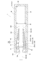
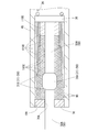
- FIG. 2 is a cross-sectional view showing the direct acting damper of the first embodiment. It is a graph which shows the relationship between the displacement amount of the rod in the linear motion damper of Embodiment 1, and a damping force.
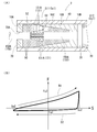
- (A) is sectional drawing which shows the linear motion damper of Embodiment 2
- (B) is a graph which shows the relationship between the displacement amount of the rod in the linear motion damper of Embodiment 2, and damping force.
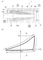
- (A) is sectional drawing which shows the linear motion damper of Embodiment 4
- (B) is a graph which shows the relationship between the displacement amount of the rod in the linear motion damper of Embodiment 4, and damping force.
- (A) is a sectional view showing a direct-acting damper of Embodiment 5
- (B) is an AA sectional view in (A). It is a graph which shows the relationship between the displacement amount of the rod in the linear-motion damper of Embodiment 5, and damping force.
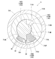
- (A) is sectional drawing which shows the rotary damper of Embodiment 6
- (B) is a graph which shows the relationship of the displacement amount and damping force which the rotor in the rotary damper of Embodiment 6 rotated and displaced.
- FIG. 21 is a cross-sectional view showing a rotary damper of a ninth embodiment.
- FIG. 21 is a cross-sectional view showing a rotary damper of a tenth embodiment. It is sectional drawing which shows the linear-motion damper of other embodiment.
- Embodiments 1 to 10 in which the linear motion damper and the rotary damper of the present invention are embodied will be described with reference to the drawings.
- the damper 1 which is the direct acting damper according to the first embodiment includes a cylinder 40 as a case, a first piston 30, a rod 50, a rod guide 70, a plurality of particles 90, and a return.
- a spring 20 is provided.
- the cylinder 40 has a cylindrical shape, and is formed with an open end 10A opened at one end of the cylindrical shape, and a closed bottom 10E formed at the other.
- the first piston 30 has a disk shape. The outer diameter of the disk-shaped first piston 30 is slightly smaller than the inner diameter of the cylinder 40. The first piston 30 is disposed in the cylinder 40.
- the cylinder 40 has the cylinder member 10B.
- the cylindrical member 10B has a cylindrical shape.
- the outer diameter of the cylindrical member 10B is substantially the same as the inner diameter of the cylinder 40.
- An inclined surface 10C is formed on the inner side of the cylindrical cylindrical member 10B such that the inner diameter gradually decreases from one end to the other end.
- a reduced diameter portion 10D is provided at the other end of the cylindrical member 10B so as to protrude to the inside of the cylindrical member 10B.
- the cylindrical member 10B has one end directed to the open end 10A of the cylinder 40 and the other end in contact with one end surface of the first piston 30 so as to be inserted into the cylinder 40 and connected to the cylinder 40.
- the cylindrical member 10 B is a part of the cylinder 40.
- the inner shape of the cylindrical member 10B which is a part of the cylinder 40, and the cross-sectional area of the rod 50 in the direction orthogonal to the central axis of the rod main body 50A changes in the central axial direction of the rod main body 50A of the rod 50 ing. Further, the inner shape of the cylindrical member 10B which is a part of the cylinder 40, and the cross-sectional shape in the direction orthogonal to the central axis of the rod body 50A of the rod 50 maintains the same state.
- the size changes in the central axis direction of The cylinder 40 has an inner space Ss1 formed therein.
- the rod 50 has a rod body 50A and a second piston 31.
- the rod body 50A has a central axis and is cylindrical and extends in one direction.
- the cylindrical rod body 50A is disposed coaxially with the cylindrical cylinder 40.
- the other end of the rod main body 50A is disposed in the cylinder 40, and one end protrudes from the open end 10A of the cylinder 40 to the outside of the cylinder 40.
- the outer diameter of the rod main body 50A is slightly smaller than the inner diameter of the reduced diameter portion 10D of the cylindrical member 10B.
- the other end of the rod main body 50A is connected to one end surface of the disk-shaped first piston 30.
- the second piston 31 has a central portion 31A and both end portions 31B.
- the central portion 31A is cylindrical.
- the outer diameter of the central portion 31A is larger than the outer diameter of the rod main body 50A.
- Both end portions 31B are in the form of a truncated cone whose outer diameter is gradually reduced as it is separated from both end surfaces of the cylindrical central portion 31A.
- the second piston 31 is disposed in the middle of the cylindrical rod main body 50A coaxially with the cylindrical rod main body 50A.
- the second piston 31 is disposed on one end surface side of the first piston 30.
- the outer diameter of the central portion 31A of the second piston 31 is smaller than the inner diameter of the cylinder 40 and the inner diameter of one end of the inclined surface 10C of the cylindrical member 10B.
- the outer diameter of the central portion 31A of the second piston 31 is substantially the same as the inner diameter of the other end of the inclined surface 10C of the cylindrical member 10B.
- the second piston 31 is a part of the rod 50.
- the cross-sectional area of the second piston 31 which is a part of the rod 50 and is located inside the cylinder 40 and is in the direction perpendicular to the central axis of the rod main body 50A changes in the central axial direction of the rod 50 There is.
- it is a part of rod 50 It is an outer side shape of the 2nd piston 31 located in the cylinder 40, Comprising:
- the cross-sectional shape of the direction orthogonal to the central axis of the rod main body 50A maintains a similar state. The size is changed in the central axis direction of the main body 50A.
- the rod guide 70 is disc-shaped and is connected to the open end 10A so as to close the open end 10A of the cylinder 40.
- a through hole 70A penetrating in the thickness direction is provided at the center of the disk-shaped rod guide 70.
- the inner diameter of the through hole 70A is slightly larger than the outer diameter of the rod body 50A.
- the through hole 70A penetrates in the central axial direction of the rod main body 50A in a state where the rod guide 70 is fixed to the open end 10A of the cylinder 40.
- the rod main body 50A is inserted through the through hole 70A of the rod guide 70 so as to be capable of reciprocating.
- the second piston 31 is located between the rod guide 70 and the first piston 30.
- the rod 50 (the rod body 50A and the second piston 31) and the first piston 30 are both reciprocally movable in the cylinder 40 in the central axis direction of the rod body 50A. That is, the rod 50 can be reciprocated with respect to the cylinder 40 in the central axis direction of the rod main body 50A.
- the damper 1 has an inner peripheral surface of the cylinder 40, an inclined surface 10C of the cylindrical member 10B and one end surface of the reduced diameter portion 10D, and a surface of the rod guide 70 opposed to one end surface of the reduced diameter portion 10D of the cylindrical member 10B.
- One space S11 is formed. That is, the first space S11 is formed inside the cylinder 40.
- a filling space S1 is formed between the inner circumferential surface of the cylinder 40 and the inclined surface 10C of the cylindrical member 10B and the surface of the rod 50. That is, the rod 50 forms a filling space S1 with the cylinder 40 in the first space S11.
- the filling space S1 is a part of the first space S11.
- the cross-sectional shape and the cross-sectional area of a part of the filling space S1 in the direction perpendicular to the central axis of the rod main body 50A at a predetermined position in the central axial direction of the rod 50 are the movement of the rod 50 in the central axial direction It changes with time.
- the rod 50 is partially housed in the first space S11 and protrudes outside.
- the damper 1 forms a second space S12 by the inner peripheral surface of the cylinder 40, one end surface of the bottom portion 10E of the cylinder 40, and the other end surface of the first piston 30.
- the second space S12 is adjacent to the first space S11 in the direction in which the rod 50 extends.
- the first space S11 and the second space S12 are parts of the inner space Ss1.
- the plurality of granular bodies 90 have a spherical shape. These granules 90 have a predetermined hardness and elasticity.
- the granules 90 are filled in the filling space S1 at a predetermined filling rate.
- the filling rate is expressed by the following equation (1).
- the internal volume of the cylinder 40 is the volume of the filling space S1 in which the particulate matter 90 is filled.
- the return spring 20 is cylindrical and extends in one direction.
- the return spring 20 is a compression coil spring.
- the return spring 20 is disposed in the second space S12.
- One end of the return spring 20 is in contact with the other end surface of the first piston 30.
- the other end of the return spring 20 is in contact with one end surface of the bottom portion 10E of the cylinder 40.
- the return spring 20 applies an elastic force to the first piston 30 toward the open end 10 A of the cylinder 40.
- the return spring 20 moves the rod 50 and the first piston 30 moved from the open end 10A side of the cylinder 40 toward the bottom 10E side from the bottom 10E of the cylinder 40 toward the open end 10A. That is, the return spring 20 applies an elastic force to the rod 50 in the central axial direction of the rod main body 50A via the first piston 30.
- the granular material 90 forms a gap G1 between the outer peripheral surface of the second piston 31 and the inclined surface 10C of the cylindrical member 10B , Passing through the gap G1).
- the inner peripheral surface of the cylinder 40 and the granular material 90 in contact with this surface between the inclined surface 10C of the cylindrical member 10B and the granular material 90 in contact with this surface, and between the adjacent granular materials 90 And, a frictional force is generated between the outer peripheral surface of the rod 50 and the granular material 90 abutting on this surface.
- the granular material 90 located in the side which the 2nd piston 31 moves is pressed by the 2nd piston 31, and is crushed. Then, the second piston 31 is pushed back in the direction opposite to the direction in which the second piston 31 moves by the elastic repulsive force generated by the crushed granular material 90.
- the damper 1 generates a damping force based on the frictional force and the like thus generated.
- the damping characteristic of the damper 1 shown in FIG. 2 is that the rod 50 and the first piston 30 move between the open end 10A of the cylinder 40 and the bottom 10E from the predetermined position Sa1 to Sc1 in the central axis direction of the rod body 50A. It shows changes in the magnitude and direction of the damping force F generated when reciprocating between the two.
- the predetermined positions Sa1 and Sc1 indicate the range in which the rod 50 and the first piston 30 can move with respect to the cylinder 40.
- the predetermined position Sa1 is a position where the rod 50 and the first piston 30 are pulled out most from the cylinder 40
- the predetermined position Sc1 is a position where the rod 50 and the first piston 30 are pushed most into the cylinder 40. It is.
- the magnitude of the damping force F increases with distance from the axis indicating the displacement amount S in the upward or downward direction.
- the damping force F is directed above the axis indicating the displacement amount S, it is directed from the bottom 10E of the cylinder 40 to the opening end 10A (hereinafter referred to as the left direction), and below the axis indicating the displacement amount S
- the right direction When it is located on the side, it faces from the open end 10A of the cylinder 40 to the bottom 10E
- the rod 50 and the first piston 30 are moved rightward (from Sa1 to Sc1 in FIG. 2). Then, the generated damping force F changes along the path of arrow B1 of the graph. Specifically, when the rod 50 and the first piston 30 move to the right, the damping force F turns to the left and gradually increases. Then, when the rod 50 and the first piston 30 are displaced and reach the position Sc1, the magnitude of the damping force F becomes Fc1.
- the gap G1 becomes smaller. For this reason, it becomes difficult for the granular material 90 located on the bottom 10E side (hereinafter referred to as the right side) from the second piston 31 to pass through the gap G1 in the left direction. For this reason, the granular material 90 located on the right side of the second piston 31 is crushed to generate a larger elastic repulsive force.
- the elastic repulsive force is applied to the second piston 31 so as to push the second piston 31 in the left direction.
- the elastic force of the return spring 20 compressed by the first piston 30 is also applied so as to push the first piston 30 in the left direction with respect to the first piston 30.
- the rod 50 and the first piston 30 are moved in the left direction (from Sc1 to Sa1 in FIG. 2). Then, the generated damping force F changes along the path of the arrow D1 of the graph. At this time, the rod 50 and the first piston 30 easily move in the left direction by the elastic repulsive force generated by the granular body 90 positioned on the right side of the second piston 31 and the elastic force of the return spring 20. Therefore, in the section for a while after the rod 50 and the first piston 30 start moving in the left direction, the magnitude of the damping force F decreases while the direction in which the damping force F is directed remains in the left direction.
- the damping force F is directed from the left to the right. Furthermore, when the rod 50 and the first piston 30 move to the left, the damping force F gradually increases in absolute value while facing the right. Then, when the rod 50 and the first piston 30 are displaced and reach the position Sa1, the magnitude of the damping force F becomes Fa1. That is, the absolute value of Fa1 is smaller than the absolute value of Fc1.
- the damper 1 can change the magnitude of the damping force F generated according to the direction in which the rod 50 and the first piston 30 move.
- the rod 50 and the first piston 30 are moved to the right again.
- the rod 50 and the first piston 30 tend to move to the right by the elastic repulsive force generated by the granular material 90 positioned on the left side of the second piston 31.
- the rod 50 and the first piston 30 start moving in the right direction, and in the section for a while, the absolute value of the damping force F decreases while the direction in which the damping force F is directed remains right (that is, the displacement amount S Approaches the axis that shows Furthermore, when the rod 50 and the first piston 30 pass in the right direction for a while, the damping force F is directed from the right to the left.
- the cross-sectional shape and the cross-sectional area of the filling space S1 in the direction orthogonal to the central axis at a predetermined position in the central axial direction of the rod main body 50A of the damper 1 change with the movement of the rod 50.
- the damper 1 changes the size of the gap G1 along with the movement of the rod 50 in the central axis direction, and the ease of passing the gap G1 of the granular material 90 changes.
- the degree of pressing the granular material 90 can be changed, and the degree of crushing the granular material 90 can be changed.
- the damper 1 can change the magnitude of the damping force as the rod 50 moves in the central axis direction.
- the damper 1 can realize desired damping characteristics with a simple structure.
- the inner shape of the cylinder 40 of the damper 1 and the size and the cross-sectional area of the cross-sectional shape in the direction orthogonal to the central axis of the rod main body 50A change in the direction of the central axis of the rod main body 50A. . Therefore, the damper 1 can easily change the cross-sectional shape and the cross-sectional area of the filling space S1 in the direction orthogonal to the central axis of the rod main body 50A.
- the damper 1 is a part of the outer shape of the rod main body 50A located in the cylinder 40, and the size and the cross-sectional area of the cross section in the direction orthogonal to the central axis of the rod main body 50A are the center of the rod main body 50A. It is changing in the axial direction. Therefore, the damper 1 can change the cross-sectional shape and the cross-sectional area of the filling space S1 in the direction orthogonal to the central axis of the rod main body 50A more variously than the case where only the inner shape of the cylinder 40 is changed.
- the cylinder 40 of the damper 1 is formed with a second space S12 adjacent to the first space S11 in the direction in which the rod 50 extends. Further, the damper 1 is provided with a return spring 20. The return spring 20 is disposed in the second space, and applies an elastic force to the rod 50 in the central axial direction. Therefore, the damper 1 can easily return the position of the rod 50 displaced by the application of an external force to the position before the application of the force.
- the damper 2 according to the second embodiment has shapes and damping characteristics of the rod body 150A of the rod 150 and the second piston 131. It differs from the first embodiment.
- the other configuration is the same as that of the first embodiment, and the same configuration is denoted by the same reference numeral and the detailed description is omitted.
- the rod main body 150A of the damper 2 is formed with a concave portion 151 formed by reducing the diameter.
- the second piston 131 of the rod 150 is formed of a plurality of pivoting pieces 131A that extend in one direction and have a flat plate shape.
- the pivoting pieces 131A are provided so as to surround the recess 151.
- the direction in which the pivoting pieces 131A expand in a flat plate shape is parallel to the central axis of the rod main body 150A, and is directed in the radial direction from this central axis.
- a through hole 131B penetrating in the plate thickness direction is provided at one end of the pivoting piece 131A which extends in one direction.
- a pin 131C is inserted into each through hole 131B of the pivoting pieces 131A, and the pivoting pieces 131A are connected to the rod main body 150A through the pins 131C. These pivoting pieces 131A are pivotable around the central axis of the pin 131C inserted into the through hole 131B. Further, a plurality of biasing members 131D are provided between the other end (hereinafter referred to as the other end of the pivoting piece 131A) of the pivoting piece 131A extending in one direction and the outer peripheral surface of the recess 151. There is.
- a compression coil spring or the like is used as the biasing member 131D, and an elastic force is applied to the other end of the pivoting piece 131A in a direction away from the outer peripheral surface of the recess 151.
- the other end of the pivoting piece 131A protrudes a predetermined size P from the outer peripheral surface of the rod 150 (see FIG. 4B).
- the second piston 131 is a part of the rod 150. That is, the cross-sectional shape and the cross-sectional area of the rod 150 in the direction perpendicular to the central axis of the rod main body 150A are the outer shape of the portion of the second piston 131 located in the cylinder 40 projecting from the outer peripheral surface of the rod 150. It changes in the central axis direction.
- Each of the other end portions of the plurality of pivoting pieces 131A is pushed in a direction approaching the outer peripheral surface of the recess 151. Then, the other end of the pivoting piece 131A approaches the recess 151 and does not protrude from the outer peripheral surface of the rod body 150A (see FIG. 4A). In addition, the pressing of the other ends of the plurality of pivoting pieces 131A in the direction approaching the outer peripheral surface of the recess 151 is stopped. Then, the other end portions of the pivoting pieces 131A are separated from the outer peripheral surface of the recess 151, and return again to a state where they project from the outer peripheral surface of the rod 150 by a predetermined dimension P (see FIG. 4B).
- the rod 150 and the first piston 30 are moved to the right (from Sa2 to Sc2 in FIG. 3B). Then, the absolute value of the generated damping force F gradually increases along the path of arrow B2 of the graph. Further, at this time, the other ends of the plurality of pivoting pieces 131A maintain a state where they project from the outer peripheral surface of the rod 150 by a predetermined dimension P. Then, when the rod 150 and the first piston 30 are displaced and reach the position Sc2, the magnitude of the damping force F becomes Fc2.
- the gap G2 (hereinafter referred to as a gap G2) between the other end of the plurality of pivoting pieces 131A and the inclined surface 10C of the cylindrical member 10B decreases. For this reason, it becomes difficult for the granular material 90 located on the right side of the second piston 131 to pass through the gap G2 in the left direction. For this reason, the granular material 90 located on the right side of the second piston 131 is pressed and crushed by the second piston 131 to generate a larger elastic repulsive force.
- the elastic repulsive force is applied to the second piston 131 so as to push the second piston 131 in the left direction.
- the elastic force of the return spring 20 compressed by the first piston 30 is also applied so as to push the first piston 30 in the left direction with respect to the first piston 30.
- the rod 150 and the first piston 30 are moved in the left direction (from Sc2 to Sa2 in FIG. 3B). Then, the magnitude of the generated damping force F changes along the path of the arrow D2 of the graph. At this time, the rod 150 and the first piston 30 easily move leftward due to the elastic repulsive force generated by the granular material 90 and the elastic force of the return spring 20.
- the other end of the plurality of pivoting pieces 131A is recessed by the granular material 90 positioned on the opening end 10A side (hereinafter referred to as the left side) from the second piston 131 It is pushed in the direction approaching the outer peripheral surface of 151.
- the other end of the pivoting piece 131A approaches the outer peripheral surface of the recess 151.
- the other ends of the plurality of pivoting pieces 131A do not protrude from the outer peripheral surface of the rod 150, and the gap G2 becomes large. That is, the volume of the filling space S2 changes with the movement of the rod 150 in the direction of the central axis of the rod body 150A.
- the granular material 90 positioned on the left side of the second piston 131 passes through the gap G2 rightward without being blocked by the second piston 131. That is, the rod 150 and the first piston 30 easily move in the left direction. Therefore, as soon as the rod 150 and the first piston 30 start moving in the left direction, the magnitude of the damping force F sharply decreases and becomes lower than the axis indicating the displacement amount S. That is, the direction in which the damping force F is directed changes rapidly from the left direction to the right direction. In addition, when the rod 150 and the first piston 30 move in the left direction, the absolute value of the damping force F does not increase as compared with the case where the rod 150 and the first piston 30 move in the right direction. Then, when the rod 150 and the first piston 30 are displaced and reach the position Sa2, the magnitude of the damping force F becomes Fa2. That is, the absolute value of Fa2 is smaller than the absolute value of Fc2.
- the sectional shape and sectional area of the filling space S2 of the volume of the filling space S2 of the damper 2 and the filling space S2 in the direction orthogonal to the central axis at a predetermined position in the central axial direction of the rod main body 150A Change.
- the damper 2 changes the size of the gap G2 along with the movement of the rod 150 in the central axis direction, and the ease of passage of the gap G2 of the granular material 90 changes.
- the degree of pressing the granular material 90 can be changed, and the degree of crushing the granular material 90 can be changed.
- the damper 2 can change the magnitude of the damping force as the rod 150 moves in the central axis direction.
- the damper 2 can also realize desired damping characteristics with a simple structure.
- the damper 2 is a second piston 131 located in the cylinder 40, and the cross-sectional shape and the cross-sectional area in the direction orthogonal to the central axis of the rod main body 150A change in the central axial direction of the rod main body 150A. Therefore, the damper 2 can change the cross-sectional shape and the cross-sectional area of the filling space S1 in the direction orthogonal to the central axis of the rod main body 150A more variously than when changing only the inner shape of the cylinder 40.
- Embodiment 3 As shown in FIGS. 5A and 5B, the damper 3 according to the third embodiment is different in the shape of the rod main body 250A of the rod 250, the point having the outer diameter changing portion 250B, and the rod guide 170 The inner diameter of the through hole 170A and the attenuation characteristics are different from those of Embodiments 1 and 2.
- the other configuration is the same as that of the first and second embodiments, and the same configuration is denoted by the same reference numeral, and the detailed description is omitted.
- the outer diameter of one end portion of the rod body 250A of the rod 250 of the damper 3 is formed larger than the outer diameter of the other end portion.
- an outer diameter changing portion 250B is provided between one end and the other end of the rod main body 250A.
- the outer diameter changing portion 250B has a truncated cone shape in which the outer diameter gradually decreases from one end of the rod main body 250A to the other end, and is continuous with one end side and the other end side of the rod main body 250A. It is formed.
- a through hole 170A penetrating in the thickness direction is provided at the center of the disk-shaped rod guide 170.
- the inner diameter of the through hole 170A is slightly larger than the outer diameter of one end of the rod body 250A.
- the rod 250 and the first piston 30 are moved rightward (from Sa3 to Sc3 in FIG. 5B). Then, the magnitude of the generated damping force F gradually increases along the path of the arrow B3 in the graph. Then, when the rod 250 and the first piston 30 are displaced rightward and reach the position Sc3, the magnitude of the damping force F becomes Fc3. At this time, by inserting one end of the rod 250 into the first space S11, the volume of the filling space S3 gradually decreases. Thereby, the filling space S3 has a large filling factor. Then, the granular material 90 filled in the filling space S3 is pressed and crushed to generate a large elastic repulsive force gradually.
- this elastic repulsive force is applied to push the rod 250 in the left direction with respect to the rod 250. Furthermore, the elastic force of the return spring 20 compressed by the first piston 30 is also applied so as to push the first piston 30 in the left direction with respect to the first piston 30.
- the rod 250 and the first piston 30 are moved leftward (from Sc3 to Sa3 in FIG. 5B). Then, the magnitude of the generated damping force F changes along the path of the arrow D3 of the graph. At this time, the rod 250 and the first piston 30 easily move leftward due to the elastic repulsive force generated by the granular material 90 and the elastic force of the return spring 20.
- the volume of the filling space S3 increases. Thereby, the filling space S3 has a small filling factor. Then, the degree of crushing of the granular material 90 filled in the filling space S3 is alleviated. Therefore, as soon as the rod 250 and the first piston 30 start moving leftward, the magnitude of the damping force F sharply decreases and becomes lower than the axis indicating the displacement amount S. That is, the direction in which the damping force F is directed changes rapidly from the left direction to the right direction. In addition, when the rod 250 and the first piston 30 move in the left direction, the absolute value of the damping force F does not increase as compared with the case where the rod 250 and the first piston 30 move in the right direction. When the rod 250 and the first piston 30 are displaced leftward and reach the position Sa3, the magnitude of the damping force F becomes Fa3. That is, the absolute value of Fa3 is smaller than the absolute value of Fc3.
- the damper 3 can move the rod 250 and the first piston 30 in the left direction by the elastic repulsive force of the particulate matter 90 filled in the filling space S3. That is, when the damper 3 uses the elastic granular body 90, the rod 250 and the first piston 30 can be moved leftward without providing the return spring 20.
- the volume of the filling space S3 of the damper 3 and the cross-sectional shape and the cross-sectional area of the filling space S3 in the direction orthogonal to the central axis at a predetermined position in the central axial direction of the rod main body 250A Change.
- the damper 3 changes the filling rate of the filling space S3 in accordance with the movement of the rod 250 in the central axis direction, changing the degree of pressing the granular body 90, and changing the degree of crushing the granular body 90. be able to.
- the damper 3 can change the magnitude of the damping force as the rod 250 moves in the central axis direction.
- the damper 3 can also realize desired damping characteristics with a simple structure.
- the damper 4 of the fourth embodiment is different from the first to third embodiments in the shape of the outer diameter changing portion 350B of the rod 350 and the damping characteristics.
- the other configuration is the same as that of the first to third embodiments, and the same configuration is denoted with the same reference numeral, and the detailed description is omitted.
- the outer diameter changing portion 350B of the rod 350 of the damper 4 is gradually changed in size from the size of the outer diameter of one end of the rod main body 350A to the size of the outer diameter of the other end. Being formed.
- the outer peripheral surface of the outer diameter changing portion 350B is divided into four regions H in the central axis direction of the outer diameter changing portion 350B. In each of the four regions H, the central portion in the central axis direction of the rod body 350A is curved in a direction away from the central axis of the rod body 350A.
- the surface area of the outer diameter changing portion 350B is larger than the surface area of the outer diameter changing portion 250B of the damper 3.
- the area in which the granular material 90 contacts is larger than the outer diameter changing portion 250B of the damper 3.
- the side with the largest outer diameter of the outer diameter changing portion 350B is disposed at one end side of the rod body 350A, and the side with the smallest outer diameter is disposed at the other end side of the rod body 350A.
- the rod 350 and the first piston 30 are moved rightward (from Sa4 to Sc4 in FIG. 6B). Then, the magnitude of the generated damping force F changes along the path of arrow B4 in the graph.
- the rod 350 and the first piston 30 are moved to the right, the granules 90 abutting on the surface of the rod 350 move to the left with respect to the rod 350.
- the granular material 90 in contact with the surfaces of the four regions H of the outer diameter changing portion 350B generates a large frictional force when crossing over the curved portions of the four regions H.
- this elastic repulsive force is applied to push the rod 350 in the left direction with respect to the rod 350. Furthermore, the elastic force of the return spring 20 compressed by the first piston 30 is also applied so as to push the first piston 30 in the left direction with respect to the first piston 30.
- the rod 350 and the first piston 30 are moved leftward (from Sc4 to Sa4 in FIG. 6B). Then, the magnitude of the generated damping force F changes along the path of the arrow D4 of the graph. At this time, the rod 350 and the first piston 30 easily move leftward due to the elastic repulsive force generated by the granular material 90 and the elastic force of the return spring 20.
- the volume of the filling space S4 increases. Thereby, the filling space S4 has a small filling factor. Then, the degree of crushing of the granular material 90 filled in the filling space S4 is alleviated. Therefore, as soon as the rod 350 and the first piston 30 start moving leftward, the magnitude of the damping force F sharply decreases and becomes lower than the axis indicating the displacement amount S. That is, the direction in which the damping force F is directed changes rapidly from the left direction to the right direction. In addition, when the rod 350 and the first piston 30 move in the left direction, the absolute value of the damping force F does not increase as compared with the case where the rod 350 and the first piston 30 move in the right direction. Then, when the rod 350 and the first piston 30 are displaced leftward and reach the position Sa4, the magnitude of the damping force F becomes Fa4. That is, the absolute value of Fa4 is smaller than the absolute value of Fc4.
- the volume of the filling space S4 of the damper 4 and the cross-sectional shape and the cross-sectional area of the filling space S4 in the direction orthogonal to the central axis at a predetermined position in the central axial direction of the rod main body 350A Change.
- the damper 4 changes the filling rate of the filling space S4 in accordance with the movement of the rod 350 in the central axis direction, changing the degree of pressing the granular body 90, and changing the degree of crushing the granular body 90. be able to.
- the damper 4 can change the magnitude of the damping force as the rod 350 moves in the central axis direction.
- the damper 4 can also realize desired damping characteristics with a simple structure.
- the point which protrudes outside and the attenuation characteristic are different from the first to fourth embodiments.
- the other configuration is the same as that of the first to fourth embodiments, and the same configuration is denoted with the same reference numeral, and the detailed description is omitted.
- the cylinder 140 is cylindrical with both ends open.
- a plurality of bulges 110 F are formed on the inner peripheral surface of the cylinder 140 in the central portion in the central axis direction of the cylinder 140.
- the bulges 110 F extend in the central axis direction of the cylinder 140 and are formed to expand in a direction away from the central axis of the cylinder 140. That is, the inner shape of the cylinder 140, and the cross-sectional shape in the direction orthogonal to the central axis of the rod main body 450A of the rod 450 described later, and the cross-sectional area change in the central axial direction of the rod main body 450A of the rod 450 .
- the rod body 450A of the rod 450 is cylindrical and extends in one direction.
- the cylindrical rod body 450A is disposed coaxially with the cylindrical cylinder 140.
- the rod body 450A protrudes from the open end 110A of each end of the cylinder 140 to the outside of the cylinder 140.
- the second piston 31 is provided coaxially with the rod 450 at a central portion in the central axis direction of the cylindrical rod main body 450A.
- a rod guide 70 is connected to each open end 110A of the cylinder 140 so as to close each open end 110A.
- the rod main body 450A is inserted through the through holes 70A of the rod guides 70 so as to be capable of reciprocating.
- the rod main body 450A and the second piston 31 are both reciprocally movable in the cylinder 140 in the central axis direction of the rod main body 450A.
- the damper 5 forms a first space S51 by the inner peripheral surface of the cylinder 140 and the opposing surfaces of the two rod guides 70.
- a filling space S5 is formed between the inner circumferential surface of the cylinder 140 and the surface of the rod 450.
- the filling space S5 is a part of the first space S51.
- the plurality of granular bodies 90 are filled in the filling space S5.
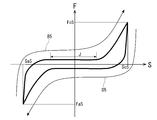
- the rod 450 is moved toward the other end of the cylinder 140 (from Sa5 to Sc5 in FIG. 8) (hereinafter referred to as the right direction). Then, as shown in FIG. 8, the magnitude of the generated damping force F changes along the path of arrow B5 of the graph.
- the granular body 90 is the outer peripheral surface of the second piston 31 Not only the gap G5 (hereinafter referred to as the gap G5) between the cylinder 140 and the inner circumferential surface of the cylinder 140, but also the bulging portion 110F passes and moves (see FIG. 7B). That is, since the granular material 90 is easily moved by the bulging portion 110F, the damping force F generated when the second piston 31 moves the section J in the right direction is suppressed from being increased.
- the bulged portion 110F is not located on the outer peripheral surface of the second piston 31.
- the granular material 90 located on the other end side (hereinafter referred to as the right side) of the cylinder 140 than the second piston 31 it becomes difficult for the granular material 90 located on the other end side (hereinafter referred to as the right side) of the cylinder 140 than the second piston 31 to move the gap G5 toward one end side of the cylinder 140 (hereinafter referred to as the left direction).
- the granular material 90 located on the right side of the second piston 31 is pressed and crushed by the second piston 31 to generate a larger elastic repulsive force.
- the damping force F rapidly increases.
- the rod 450 is displaced rightward and reaches the position Sc5
- the magnitude of the damping force F becomes Fc5.
- the rod 450 is moved in the left direction (from Sc5 to Sa5 in FIG. 8). Then, the magnitude of the generated damping force F changes along the path of the arrow D5 of the graph. At this time, the rod 450 is easily moved in the left direction by the elastic repulsive force generated by the granular material 90. For this reason, as soon as the rod 450 starts to move in the left direction, the damping force F rapidly decreases and becomes lower than the axis indicating the displacement amount S. That is, the direction in which the damping force F is directed changes rapidly from the left direction to the right direction. Then, when the second piston 31 moves in the left direction in the section J, the granular material 90 moves not only through the gap G5 but also through the bulging portion 110F. As a result, the absolute value of the damping force F generated when the second piston 31 moves the section J in the left direction can be prevented from becoming large. (In other words, it is possible to suppress the downward separation from the axis indicating the displacement amount S.)
- the bulging portion 110F is not located on the outer peripheral surface of the second piston 31. For this reason, it becomes difficult for the granular material 90 located on the left side of the second piston 31 to move the gap G5 in the right direction. For this reason, the granular material 90 located on the left side of the second piston 31 is pressed and crushed by the second piston 31 to generate a larger elastic repulsive force.
- the absolute value of the damping force F rapidly increases.
- the rod 450 is displaced leftward to reach the position Sa5, the magnitude of the damping force F becomes Fa5.
- the rod 450 is moved to the right again.
- the rod 450 is likely to move to the right due to the elastic repulsive force generated by the granular material 90.
- the absolute value of the damping force F sharply decreases and becomes higher than the axis indicating the displacement amount S. That is, the direction in which the damping force F is directed changes rapidly from the right direction to the left direction.
- Damper 5 is suppressed that the absolute value of damping force F which arises when 2nd piston 31 moves section J becomes large. That is, the damper 5 can change the magnitude of the generated damping force F according to the position where the section J is provided.
- the cross-sectional shape and the cross-sectional area of the filling space S5 in the direction orthogonal to the central axis at a predetermined position in the central axial direction of the rod main body 450A of the damper 5 change with the movement of the rod 450.
- the ease with which the gap G5 of the granular material 90 passes is changed.
- the degree of pressing the granular material 90 can be changed, and the degree of crushing the granular material 90 can be changed.
- the damper 5 can change the magnitude of the damping force as the rod 450 moves in the central axis direction.
- the damper 5 can also realize desired damping characteristics with a simple structure.
- the damper 5 can easily change the cross-sectional shape and the cross-sectional area of the filling space S5 in the direction orthogonal to the central axis of the rod main body 450A.
- Embodiment 6 The rotary damper 6 according to the sixth embodiment, as shown in FIG. 9, includes a cylinder 340 as a case, a rotor 60, and a plurality of particles 90.
- the cylinder 340 is cylindrical and has an open end open at one end of the cylinder and a closed bottom at the other end (not shown).
- the cylinder 340 also has a filling member 310G.
- the filling member 310 ⁇ / b> G has a circular outer shape, and has a cylindrical shape in which a hole 310 ⁇ / b> M penetrating inside is formed.
- the hole 310M is formed by a first arc surface 310H, a second arc surface 310J, a first plane 310K, and a second plane 310L.
- Each of the first arc surface 310H and the second arc surface 310J is an arc surface.
- the first plane 310K and the second plane 310L are planes.
- the radius dimension of the second arc surface 310J is larger than the radius dimension of the first arc surface 310H.
- the arc-shaped central axis of the first arc surface 310H is coaxially disposed with the central axis of the cylindrical filling member 310G.
- the central axis of the arc-shaped second arcuate surface 310J is disposed at a predetermined distance from the central axis of the cylindrical filling member 310G.
- the dimension from one end in the circumferential direction of the second arc surface 310J to the central axis of the cylindrical filling member 310G is from the other end in the circumferential direction of the second arc surface 310J to the central axis of the filling member 310G.
- the central axis of the arc-shaped second arc surface 310J is separated from the central axis of the cylindrical filling member 310G so as to be larger than the dimension.
- the first flat surface 310K connects one end in the circumferential direction of the second arc surface 310J and the other end in the circumferential direction of the first arc surface 310H.
- the second flat surface 310L connects the other end of the second arc surface 310J in the circumferential direction and one end of the first arc surface 310H in the circumferential direction.
- the first flat surface 310K and the second flat surface 310L are parallel to the central axis of the cylindrical filling member 310G and extend radially from the central axis of the filling member 310G.
- the cylindrical filling member 310 ⁇ / b> G is inserted into the cylinder 340, and is connected to the cylinder 340 in a state where one end face of the cylindrical shape is in contact with one end face of the bottom of the cylinder 340.
- the rotor 60 has a rotating shaft 60A and a rotor main body 60B.
- the pivot shaft 60A has a cylindrical shape and extends in one direction.
- the cylindrical rotation shaft 60A is disposed coaxially with the cylindrical cylinder 340.
- the other end of the pivot shaft 60A is disposed in the hole 310M of the filling member 310G of the cylinder 340.
- a part of the outer peripheral surface of the other end of the pivot shaft 60A opposes the first arc surface 310H forming the hole 310M with a gap.
- one end of the pivot shaft 60A protrudes from the open end of the cylinder 340 to the outside of the cylinder 340 (not shown).
- the rotor main body 60B has a flat plate shape.
- the rotor main body 60B is parallel to the central axis of the pivot shaft 60A in a flat plate-like expanding direction, and is connected to the pivot shaft 60A radially from the central axis of the pivot shaft 60A.
- a disc-like rod guide is connected to the open end of the cylinder 340 so as to close the open end of the cylinder 340 (not shown).
- a through hole penetrating in the thickness direction is provided at the center of the disc-like rod guide (not shown).
- the inner diameter of the through hole is slightly larger than the outer diameter of the pivot shaft 60A (not shown).
- the through hole penetrates in the central axis direction of the pivot shaft 60A (not shown) in a state where the rod guide is fixed to the open end of the cylinder 340.
- a pivot shaft 60A is rotatably inserted through the through hole of the rod guide (not shown).
- the pivot shaft 60A and the rotor main body 60B are both pivotable within the cylinder 340 about the central axis of the pivot shaft 60A. That is, the rotor 60 has a pivot shaft 60A which is partially housed inside the cylinder 340 and protrudes to the outside, and is rotatable around the pivot shaft 60A with respect to the cylinder 340.
- the rotary damper 6 has each surface (a first arc surface 310H, a second arc surface 310J, a first flat surface 310K, and a second flat surface 310L) forming the hole 310M of the filling member 310G, and one end surface of the bottom of the cylinder 340
- a space S61 is formed by the surface of the rod guide facing one end face of the bottom portion. That is, the space S61 is formed inside the cylinder 340.
- a filling space S6 is formed between the second arc surface 310J and the surface of the rotor 60.
- the filling space S6 is a part of the space S61. That is, the rotor 60 forms a filling space S6 with the cylinder 340.
- An elastic granular particle 90 having a spherical shape is filled in the filling space S6 at a predetermined filling rate.
- the dimension to the central axis of the cylindrical filling member 310G increases as the second arc surface 310J of the filling member 310G goes from the other end in the circumferential direction to one end. That is, the cross-sectional shape and the cross-sectional area of the filling space S6 in the direction orthogonal to the rotation direction of the rotor 60 at a predetermined position in the circumferential direction of the rotation shaft 60A change with the rotation of the rotor 60.
- the cross-sectional area of the filling space S6 in the direction orthogonal to the rotation direction of the rotor 60 gradually increases in a predetermined section from the predetermined position in the rotation direction of the rotor 60.
- the inner shape of the filling member 310G of the cylinder 340, and the cross-sectional shape and the cross-sectional area in the direction orthogonal to the rotation direction of the rotor 60 change in the rotation direction of the rotor 60.
- the granular material 90 filled in the filling space S6 is a gap G6 between the second arc surface 310J and the rotor main body 60B (hereinafter referred to as a gap Move through G6).
- the rotor body 60B is pushed back by the elastic repulsive force generated by the granular material 90 crushed by the rotor body 60B.
- the rotary damper 6 generates a damping force in the direction opposite to the direction in which the rotor 60 pivots based on the frictional force and the like thus generated.
- the rotor 60 is pivoted from the first flat surface 310K toward the second flat surface 310L (hereinafter, referred to as counterclockwise direction). That is, it is rotated from Sa6 to Sc6 in FIG. Then, the magnitude of the generated damping force F changes along the path of arrow B6 in the graph. Specifically, as the rotor 60 pivots counterclockwise, the gap G6 decreases. Therefore, the granular material 90 located on the second plane 310L side (hereinafter referred to as the right side) from the rotor main body 60B passes the gap G6 from the second plane 310L to the first plane 310K (hereinafter referred to as clockwise). It becomes difficult.
- the rotor 60 is rotated clockwise. That is, it is rotated from Sc6 to Sa6 in FIG. Then, the magnitude of the generated damping force F changes along the path of the arrow D6 in the graph. At this time, the rotor 60 is easy to rotate clockwise due to the elastic repulsive force generated by the particulate matter 90 positioned on the right side of the rotor main body 60B. For this reason, as soon as the rotor 60 starts to rotate clockwise, the magnitude of the damping force F sharply decreases and becomes lower than the axis indicating the displacement amount S. That is, the direction in which the damping force F is directed changes from clockwise to counterclockwise.
- the granular material 90 located on the first plane 310K side (hereinafter referred to as the left side) from the rotor main body 60B passes the gap G6 in the counterclockwise direction. It becomes easy to do. Therefore, when the rotor 60 passes the predetermined position Sx6 in the clockwise direction, the absolute value of the damping force F gradually decreases (that is, it gradually approaches the axis indicating the displacement amount S). Furthermore, when the rotor 60 passes the predetermined position Sy6 in the clockwise direction, the granular material 90 located on the left side of the rotor main body 60B is crushed to generate a larger elastic repulsive force. As a result, the absolute value of the damping force F rapidly increases. Then, when the rotor 60 pivots clockwise to reach the position Sa6, the magnitude of the damping force F becomes Fa6.
- the rotor 60 is pivoted counterclockwise again.
- the absolute value of the damping force F rapidly decreases as soon as the rotor 60 starts rotating counterclockwise. It is above the axis shown. That is, the direction in which the damping force F is directed changes rapidly from counterclockwise to clockwise.
- the absolute value of the damping force F generated by the rotary damper 6 gradually increases from the position Sy6 toward the position Sx6. That is, the rotary damper 6 can change the absolute value of the damping force F according to the angle at which the rotor 60 rotates.
- the cross-sectional shape and the cross-sectional area of the filling space S6 in the direction orthogonal to the direction in which the rotor 60 pivots at a predetermined position in the circumferential direction of the pivot shaft 60A of the rotary damper 6 Change.
- the size of the gap G6 changes in the direction in which the rotor 60 rotates in the rotary damper 6, and the ease with which the gap G6 of the granular material 90 passes is changed.
- the rotary damper 6 can change the degree of pressing the granular material 90 in the direction in which the rotor 60 rotates, and can change the degree of crushing the granular material 90.
- the rotary damper 6 can change the magnitude of the damping force in the direction in which the rotor 60 rotates.
- the rotary damper 6 can also realize desired damping characteristics with a simple structure.
- the cross-sectional area of the filling space S6 in the direction orthogonal to the direction in which the rotor 60 of the rotary damper 6 rotates gradually increases in a predetermined section from a predetermined position in the direction in which the rotor 60 rotates. Therefore, when the rotary damper 6 rotates the rotor 60 in a predetermined section from a predetermined position in the rotation direction of the rotor 60, the degree of pressing the granular material 90 can be gradually changed. For this reason, the rotary damper 6 can gradually change the magnitude of the damping force from the predetermined position in the rotation direction of the rotor 60 to the predetermined section.
- the inner shape of the cylinder 340 of the rotary damper 6 and the cross-sectional shape and the cross-sectional area in the direction orthogonal to the direction in which the rotor 60 rotates changes in the direction in which the rotor 60 rotates. Therefore, the rotary damper 6 can easily change the cross-sectional shape and the cross-sectional area of the filling space S6 orthogonal to the direction in which the rotor 60 rotates.
- the rotary damper 7 of the seventh embodiment differs from the sixth embodiment in the shape of the second circular arc surface 410J and the damping characteristic as shown in FIGS. 10 (A) and 10 (B).
- the other configuration is the same as that of the sixth embodiment, and the same configuration is denoted by the same reference numeral, and the detailed description is omitted.
- the curvature of the second arcuate surface 410J of the rotary damper 7 is formed to increase from the one end and the other end in the circumferential direction toward the center in the circumferential direction.
- the dimension between the circumferential center portion of the second arc surface 410J and the central axis of the cylindrical filling member 410G is the one end or the other end portion of the second arc surface 410J in the circumferential direction and the cylindrical filling member 410G.
- the dimension between one end in the circumferential direction of the second arc surface 410J and the other end in the circumferential direction of the first arc surface 410H is the size of the other end in the circumferential direction of the second arc surface 410J and the circumference of the first arc surface 410H. It is the same as the dimension between one end of the direction.
- the rotary damper 7 has a first arc surface 410H, a second arc surface 410J, a first flat surface 410K, and a second flat surface 410L, one end surface of the bottom of the cylinder 440, and a surface of a rod guide facing one end surface of the bottom A space S71 is formed. Further, in the space S71, a filling space S7 is formed between the second arc surface 410J and the surface of the rotor 60.
- the granular material 90 filled in the filling space S7 is a gap G7 between the second arc surface 410J and the rotor main body 60B (hereinafter referred to as a gap Move through G7).
- the rotor 60 is pivoted counterclockwise. That is, it is rotated from Sa7 to Sc7 in FIG. 10 (B). Then, the magnitude of the generated damping force F changes along the path of arrow B7 in the graph. Specifically, as the rotor 60 pivots counterclockwise and the rotor main body 60B approaches the center of the second arc surface 410J in the circumferential direction, the gap G7 increases. For this reason, the granular material 90 located on the right side of the rotor main body 60B easily passes through the gap G7 in the clockwise direction. Therefore, the degree of crushing of the granular material 90 located on the right side of the rotor main body 60B is alleviated, and the generated elastic repulsive force is reduced. Thus, the magnitude of the damping force F gradually decreases as the rotor 60 pivots counterclockwise and the rotor body 60B approaches the circumferential center of the second arc surface 410J.
- the gap G7 becomes smaller. Therefore, it is difficult for the granular material 90 positioned on the right side of the rotor main body 60B to pass through the gap G7 clockwise. For this reason, the granular material 90 located on the right side of the rotor main body 60B is pressed and crushed by the rotor main body 60B to generate a larger elastic repulsive force.
- the magnitude of the damping force F gradually increases.
- the rotor 60 is rotated clockwise. That is, it is rotated from Sc7 to Sa7 in FIG. 10 (B). Then, the magnitude of the generated damping force F changes along the path of the arrow D7 of the graph. At this time, the rotor 60 is easy to rotate clockwise due to the elastic repulsive force generated by the particulate matter 90 positioned on the right side of the rotor main body 60B. For this reason, as soon as the rotor 60 starts to rotate clockwise, the magnitude of the damping force F sharply decreases and becomes lower than the axis indicating the displacement amount S. That is, the direction in which the damping force F is directed changes from clockwise to counterclockwise.
- the gap G7 becomes larger.
- the granular material 90 located on the left side of the rotor main body 60B easily passes the gap G7 in the counterclockwise direction. Therefore, the degree of crushing of the granular material 90 located on the left side of the rotor main body 60B is alleviated, and the generated elastic repulsive force is reduced.
- the absolute value of the damping force F gradually decreases. (In other words, it approaches the axis indicating the displacement amount S.)
- the rotor 60 is pivoted counterclockwise again.
- the absolute value of the damping force F rapidly decreases as soon as the rotor 60 starts rotating counterclockwise. It is above the axis shown. That is, the direction in which the damping force F is directed changes rapidly from counterclockwise to clockwise.
- the absolute value of the damping force F generated by the rotary damper 7 gradually decreases from each of the position Sy7 and the position Sx7 as it approaches the center of the second circular arc surface 410J in the circumferential direction.
- the cross-sectional shape and the cross-sectional area of the filling space S7 in the direction orthogonal to the direction in which the rotor 60 pivots at a predetermined position in the circumferential direction of the pivot shaft 60A of the rotary damper 7 Change.
- the size of the gap G7 changes in the direction in which the rotor 60 rotates in the rotary damper 7, and the ease with which the gap G7 of the granular material 90 passes is changed.
- the rotary damper 7 can change the degree of pressing the granular material 90 in the direction in which the rotor 60 pivots, and can change the degree of crushing of the granular material 90.
- the rotary damper 7 can change the magnitude of the damping force in the direction in which the rotor 60 rotates.
- the rotary damper 7 can also realize desired damping characteristics with a simple structure.
- the rotary damper 8 of the eighth embodiment differs from the sixth and seventh embodiments in the shape of the second circular arc surface 510J and the damping characteristics.
- the other configuration is the same as that of the sixth and seventh embodiments, and the same configuration is denoted by the same reference numeral, and the detailed description is omitted.
- the second circular arc surface 510J of the rotary damper 8 is formed to have a smaller curvature as it goes from the one end and the other end in the circumferential direction to the center in the circumferential direction.
- the dimension between the circumferential center portion of the second arc surface 510J and the central axis of the cylindrical filling member 510G is the one end or the other end portion of the second arc surface 510J in the circumferential direction and the cylindrical filling member 510G.
- the rotary damper 8 has a first arc surface 510H, a second arc surface 510J, a first flat surface 510K, and a second flat surface 510L, one end face of the bottom of the cylinder 540, and a face of the rod guide facing one end face of the bottom A space S81 is formed. Further, in the space S81, a filling space S8 is formed between the second arc surface 510J and the surface of the rotor 60.
- the granular material 90 filled in the filling space S8 is a gap G8 between the second arc surface 510J and the rotor main body 60B (hereinafter referred to as a gap Move through G8).
- the rotor 60 is pivoted counterclockwise. That is, it is rotated from Sa8 to Sc8 in FIG. Then, the magnitude of the generated damping force F changes along the path of arrow B8 in the graph. Specifically, as the rotor 60 pivots counterclockwise and the rotor main body 60B approaches the center of the second arc surface 510J in the circumferential direction, the gap G8 decreases. Therefore, it is difficult for the granular material 90 positioned on the right side of the rotor main body 60B to pass through the gap G8 in the clockwise direction. For this reason, the granular material 90 located on the right side of the rotor main body 60B is pressed and crushed by the rotor main body 60B to generate a larger elastic repulsive force. Thus, the rotor 60 rotates counterclockwise, and the damping force F gradually increases as the rotor body 60B approaches the circumferential center of the second arc surface 510J.
- the gap G8 becomes large.
- the granular material 90 located on the right side of the rotor main body 60B easily passes through the gap G8 in the clockwise direction. Therefore, the degree of crushing of the granular material 90 located on the right side of the rotor main body 60B is alleviated, and the generated elastic repulsive force is reduced.
- the damping force F gradually decreases.
- the rotor 60 is moved clockwise. That is, it is rotated from Sc8 to Sa8 in FIG. Then, the magnitude of the generated damping force F changes along the path of the arrow D8 in the graph. At this time, the rotor 60 is easy to rotate clockwise due to the elastic repulsive force generated by the particulate matter 90 positioned on the right side of the rotor main body 60B. For this reason, as soon as the rotor 60 starts to rotate clockwise, the magnitude of the damping force F sharply decreases and becomes lower than the axis indicating the displacement amount S. That is, the direction in which the damping force F is directed changes from clockwise to counterclockwise.
- the gap G8 becomes smaller.
- the granular material 90 positioned on the left side of the rotor main body 60B hardly passes the gap G8 in the counterclockwise direction.
- the granular material 90 located on the left side of the rotor main body 60B is pressed and crushed by the rotor main body 60B to generate a larger elastic repulsive force.
- the absolute value of the damping force F gradually increases.
- the gap G8 becomes large.
- the granular material 90 located on the left side of the rotor main body 60B easily passes the gap G8 in the counterclockwise direction. Therefore, the degree of crushing of the granular material 90 located on the left side of the rotor main body 60B is alleviated, and the generated elastic repulsive force is reduced.
- the absolute value of the damping force F gradually decreases. (In other words, it approaches the axis indicating the displacement amount S.)
- the rotor 60 is pivoted counterclockwise again.
- the absolute value of the damping force F rapidly decreases as soon as the rotor 60 starts rotating counterclockwise. It is above the axis shown. That is, the direction in which the damping force F is directed changes rapidly from counterclockwise to clockwise.
- the absolute value of the damping force F generated by the rotary damper 8 gradually increases from each of the position Sy8 and the position Sx8 as it approaches the center of the second arc surface 510J in the circumferential direction.
- the cross-sectional shape and the cross-sectional area of the filling space S8 in the direction orthogonal to the direction in which the rotor 60 pivots at a predetermined position in the circumferential direction of the pivot shaft 60A of the rotary damper 8 Change.
- the size of the gap G8 changes in the direction in which the rotor 60 rotates, and the ease with which the gap G8 of the granular material 90 passes is changed.
- the rotary damper 8 can change the degree of pressing the granular material 90 in the direction in which the rotor 60 rotates, and change the degree of crushing the granular material 90.
- the rotary damper 8 can change the magnitude of the damping force in the direction in which the rotor 60 rotates.
- the rotary damper 8 can also realize desired damping characteristics with a simple structure.
- the rotary damper 9 of the ninth embodiment differs from the sixth to eighth embodiments in the shape of the hole 710P of the filling member 710G and the shape of the rotor main body 160B of the rotor 160 as shown in FIG.
- the other configuration is the same as that of the sixth to eighth embodiments, and the same configuration is denoted with the same reference numeral, and the detailed description is omitted.
- the hole 710P formed in the filling member 710G of the rotary damper 9 is formed by the first arc surface 710H, the second arc surface 710J, the third arc surface 710M, the first plane 710K, the second plane 710L, and the third plane 710N. It is done.
- Each of the first circular arc surface 710H, the second circular arc surface 710J, and the third circular arc surface 710M is a circular arc surface.
- the radius dimensions of the first circular arc surface 710H, the second circular arc surface 710J, and the third circular arc surface 710M are the largest in the second circular arc surface 710J, the second largest in the first circular arc surface 710H, and the smallest in the third circular arc surface 710M. .
- the central axes of the first circular arc surface 710H, the second circular arc surface 710J, and the third circular arc surface 710M are formed coaxially with the central axis of the cylindrical filling member 710G.
- the first plane 710K, the second plane 710L, and the third plane 710N are planes.
- the first plane 710K connects one end in the circumferential direction of the second circular arc surface 710J and the other end in the circumferential direction of the first circular arc surface 710H.
- the second flat surface 710L connects the other end of the second arc surface 710J in the circumferential direction and one end of the third arc surface 710M in the circumferential direction.
- the third flat surface 710N connects one end in the circumferential direction of the first arc surface 710H and the other end in the circumferential direction of the third arc surface 710M.
- the first flat surface 710K, the second flat surface 710L, and the third flat surface 710N are parallel to the central axis of the cylindrical filling member 710G and radially extend from the central axis of the filling member 710G.
- the rotor main body 160B of the rotor 160 has a first shaft portion 160C, a second shaft portion 160D, and a convex portion 160E.
- the first shaft portion 160C and the second shaft portion 160D are semi-cylindrical and extend in one direction.
- the radius of the semi-cylindrical first shaft portion 160C is smaller than the radius of the semi-cylindrical second shaft portion 160D.
- the first shaft portion 160C and the second shaft portion 160D are disposed coaxially with each other with their arc-shaped faces directed in opposite directions.
- the convex portion 160E is provided at one end portion in the circumferential direction of the arc-shaped surface of the second shaft portion 160D so as to protrude in the radial direction away from the central axes of the first shaft portion 160C and the second shaft portion 160D.
- the rotation shaft is connected to the rotor main body 160B coaxially with the central axis of the first shaft portion 160C and the second shaft portion 160D of the rotor main body 160B, and the rod guide penetrated through the open end of the cylinder 740 It is inserted into the hole and protrudes out of the cylinder 740 (not shown).
- the rotor body 160 B is part of the rotor 160 located within the cylinder 740.
- the cross-sectional shape and the cross-sectional area in the direction orthogonal to the rotation direction of the rotor 160 change in the circumferential direction of the rotation shaft.
- the arc-shaped surface of the first shaft portion 160C is opposed to the third arc surface 710M with a gap.
- the arc-shaped surface of the second shaft portion 160D is opposed to the first arc surface 710H with a gap.
- the tip of the convex portion 160E is opposed to the second circular arc surface 710J with a gap G9 (hereinafter referred to as a gap G9).
- the dimension between the arc-shaped surface of the first shaft portion 160C and the second arc surface 710J is between the arc-shaped surface of the second shaft portion 160D and the second arc surface 710J. Larger than
- the rotary damper 9 has the respective surfaces forming the holes 710P of the filling member 710G (a first arc surface 710H, a second arc surface 710J, a third arc surface 710M, a first plane 710K, a second plane 710L, and a third plane 710N).
- a space S91 is formed by one end face of the bottom portion of the cylinder 740 and the surface of the rod guide opposed to one end face of the bottom portion.
- the arc-shaped surface of the second shaft portion 160D, the arc-shaped surface of the first shaft portion 160C, the surface of the convex portion 160E, and the second arc surface 710J The filling space S9 is formed between them.
- the filling space S9 is a part of the space S91.
- the granular material 90 is filled in the filling space S9 at a predetermined filling rate.
- the rotor 160 is pivoted counterclockwise. At this time, the second shaft portion 160D enters the filling space S9, whereby the volume of the filling space S9 gradually decreases. As a result, the granular material 90 is pressed and crushed to generate a large elastic repulsive force. The elastic repulsive force is applied to the second shaft portion 160D so as to push the second shaft portion 160D out of the filling space S9.
- the rotor 160 is rotated clockwise. At this time, the rotor 160 is easily turned clockwise due to the elastic repulsive force generated by the granular material 90. For this reason, as soon as the rotor 160 starts to rotate clockwise, the magnitude of the damping force F sharply decreases.
- the volume of the filling space S9 of the rotary damper 9 changes with the rotation of the rotor 160.
- the rotary damper 9 can change the degree of pressing the granular material 90 in the direction in which the rotor 160 rotates, and can change the degree of crushing of the granular material 90.
- the magnitude of the damping force can be changed in the direction in which the rotor 160 rotates.
- the rotary damper 9 can also realize desired damping characteristics with a simple structure.
- the outer shape of the rotor main body 160B located in the cylinder 740 of the rotary damper 9, and the cross-sectional shape and the cross-sectional area in the direction orthogonal to the rotation direction of the rotor 160 change in the circumferential direction of the rotation shaft There is. Therefore, as compared with the case where only the inner shape of the cylinder 740 is changed, the rotary damper 9 can change the cross-sectional shape and the cross-sectional area of the filling space S9 orthogonal to the rotating direction of the rotor 160 more variously.
- the rotary damper 10 of the tenth embodiment differs from the sixth to ninth embodiments in the shape of the hole 810M of the filling member 810G and the shape of the rotor main body 260B of the rotor 260, as shown in FIG.
- the other configuration is the same as that of the sixth to ninth embodiments, and the same configuration is denoted by the same reference numeral, and the detailed description is omitted.
- the hole 810M of the filling member 810G of the rotary damper 10 is formed of a second arc surface 810J and a plurality of bulges 810F.
- the second circular arc surface 810J has a circular cross section perpendicular to the central axis of the cylindrical filling member 810G.
- the central axis of the second arc surface 810J is coaxially disposed with the central axis of the cylindrical filling member 810G.
- the plurality of bulges 810F extend in the central axis direction of the cylindrical filling member 810G and are formed to expand in a direction away from the central axis of the filling member 810G.
- the rotor body 260B of the rotor 260 has an oval cross section perpendicular to the central axis of the rotor body 260B and extends in one direction.
- the rotation shaft which is a rotation shaft, is connected to the rotor main body 260B coaxially with the central axis of the oval circular rotor main body 260B, and is inserted into the through hole of the rod guide connected to the open end of the cylinder 840. It protrudes outside the 840 (not shown).
- the outer peripheral surface of the elongated circular rotor main body 260B in the long diameter direction is opposed to the second arc surface 810J and the plurality of bulges 810F with a gap G10 (hereinafter referred to as a gap G10).
- the rotary damper 10 has each surface (a second arc surface 810J and a bulge 810F) forming the hole 810M of the filling member 810G, one end face of the bottom of the cylinder 840, and a face of the rod guide facing one end of the bottom Space S101 is formed. Further, in the space S101, a filling space S10 is formed between the outer peripheral surface of the rotor main body 260B and each surface forming the holes 810M. The filling space S10 is a part of the space S101. The granular material 90 is filled in the filling space S10 at a predetermined filling rate.
- the rotor 260 is rotated in one direction or the other direction around the central axis of the rotation axis.
- the outer peripheral surface located in the major axis direction of the rotor main body 260B moves opposite to the second arc surface 810J, the size of the gap G10 does not change even if the rotor 260 rotates. Therefore, while the rotor 260 rotates in one direction or the other direction and the outer circumferential surface located in the major axis direction of the rotor main body 260B moves the second circular arc surface 810J, the absolute value of the generated damping force does not substantially change.
- the outer peripheral surface located in the long diameter direction of the rotor main body 260B moves opposite to the swelled portion 810F (state of the two-dot chain line in FIG. 13)
- the outer peripheral surface located in the long diameter direction of the rotor main body 260B is the gap G10 It becomes large compared with the case where it faces the 2nd circular arc surface 810J.
- the granular material 90 filled in the filling space S10 easily passes through the gap G10. Therefore, the damping force generated when the outer peripheral surface located in the long diameter direction of the rotor main body 260B moves the bulging portion 810F is when the outer peripheral surface located in the long diameter direction of the rotor main body 260B moves the second arc surface 810J. It becomes smaller than the generated damping force.
- the cross-sectional shape and the cross-sectional area of the filling space S10 in the direction orthogonal to the direction in which the rotor 260 rotates at a predetermined position in the circumferential direction of the rotary shaft of the rotary damper 10 change with the rotation of the rotor 260.
- the size of the gap G10 changes in the direction in which the rotor 260 rotates, and the ease with which the gap G10 of the granular material 90 passes is changed.
- the rotary damper 10 can change the degree of pressing the granular material 90 in the direction in which the rotor 260 rotates, and change the degree of crushing the granular material 90.
- the rotary damper 10 can change the magnitude of the damping force in the direction in which the rotor 260 rotates.
- the rotary damper 10 can also realize desired damping characteristics with a simple structure.
- the present invention is not limited to the embodiments 1 to 10 described above with reference to the drawings.
- the cylindrical member is provided with the inclined portion having the inclined surface, as shown in FIG. 14, the cylindrical member has a plurality of cylindrical members 110B having different outer diameters and lengths. It may overlap and form and may form slope 110C and diameter reduction part 110D. In this case, the cylindrical member 110B can be easily formed.
- the size of the particles is uniform, but particles of a plurality of particle sizes may be used.
- the rod and the pivoting shaft protrude from one side (open end) of the cylinder to the outside, but the rod and the pivoting shaft are each from both ends of the cylinder It may protrude outside.
- the particles have elasticity, a material having no elasticity may be used to form the particles. Also, elastic particles and non-elastic particles may be used in combination.
- the cylinder is provided with the bulging portion, but a shape may be provided which protrudes in the direction approaching the central axis of the cylinder.
Landscapes
- Engineering & Computer Science (AREA)
- General Engineering & Computer Science (AREA)
- Mechanical Engineering (AREA)
- Physics & Mathematics (AREA)
- Acoustics & Sound (AREA)
- Aviation & Aerospace Engineering (AREA)
- Vibration Dampers (AREA)
- Vibration Prevention Devices (AREA)
- Fluid-Damping Devices (AREA)
Abstract
簡易な構造で所望の減衰特性を有した直動ダンパ及びロータリーダンパを提供する。 ダンパ(1)は、シリンダ(40)、ロッド(50)、及び複数の粒状体(90)を備えている。シリンダ(40)は内部に第1空間(S11)が形成されている。ロッド(50)は第1空間(S11)内に一部が収納されて外部に突出している。また、ロッド(50)はシリンダ(40)に対して中心軸方向に往復移動自在である。また、ロッド(50)は第1空間(S11)内でシリンダ(40)との間に充填空間(S1)を形成している。複数の粒状体(90)は充填空間(S1)に充填される。また、ロッド(50)の中心軸方向の所定の位置における中心軸に直交する方向の断面形状及び断面積が、ロッド(50)の移動に伴って変化する。
Description
本発明は直動ダンパ及びロータリーダンパに関する。
特許文献1は従来の直動ダンパを開示している。この直動ダンパ(damper)は、シリンダ(cylinder)と一対のキャップ(cap)に囲まれた空間に粒状体である鋼球が充填されており、ロッド(rod)の動きに伴って、粒状体が充填された中をシリンダに対して相対的にピストン(piston)が変位する構造になっている。一対のキャップはそれぞれ一対のスプリング(spring)により常に粒状体が収納されている空間の体積が減少する方向に付勢されている。また、シリンダの外周には電磁石が設けられている。
この直動ダンパは、シリンダに対してピストンが相対的に変位するようにロッドを変位させると、粒状体がピストンの動きに伴って流動して粒状体同士や、粒状体とピストン等とで摩擦力が生じ、これにより減衰力を生じる。具体的には、粒状体を流動させるために必要な力が、スプリングからキャップが付勢されている力よりも大きくなると、この力とスプリングからキャップが付勢されている力が釣り合う位置までキャップが変位する。キャップが変位すると、粒状体が充填されているケース(case)内の容積が増加してシリンダ内に空隙ができる。これにより、この直動ダンパは粒状体の流動が促進され、ピストンが粒状体を押しのけて動いて減衰力を生じる。
この直動ダンパは、シリンダに対してピストンが相対的に変位するようにロッドを変位させると、粒状体がピストンの動きに伴って流動して粒状体同士や、粒状体とピストン等とで摩擦力が生じ、これにより減衰力を生じる。具体的には、粒状体を流動させるために必要な力が、スプリングからキャップが付勢されている力よりも大きくなると、この力とスプリングからキャップが付勢されている力が釣り合う位置までキャップが変位する。キャップが変位すると、粒状体が充填されているケース(case)内の容積が増加してシリンダ内に空隙ができる。これにより、この直動ダンパは粒状体の流動が促進され、ピストンが粒状体を押しのけて動いて減衰力を生じる。
特許文献1の直動ダンパはロッドが延びる方向を水平方向にして配置した状態でシリンダに対してロッドを移動させると、ロッドがシリンダに対して移動する移動範囲の全体にわたり所定の大きさの減衰力を生じる。そして、この直動ダンパは電磁石に電流を流すことによって、粒状体の結合力を強め、粒状体間の摩擦力を大きくする。これにより、この直動ダンパは減衰力を大きくする。つまり、この直動ダンパは電磁石に流れる電流の大きさを制御することによって、減衰特性を変化させることができる。
しかし、この直動ダンパは、電磁石や、電磁石に所定の電流を流すための仕組みを設ける必要があるため、構造が複雑である。
しかし、この直動ダンパは、電磁石や、電磁石に所定の電流を流すための仕組みを設ける必要があるため、構造が複雑である。
本発明は、上記従来の実情に鑑みてなされたものであって、簡易な構造で所望の減衰特性を有した直動ダンパ及びロータリーダンパ(rotary damper)を提供することを解決すべき課題としている。
第1発明の直動ダンパは、シリンダ、ロッド、及び複数の粒状体を備えている。シリンダは内部に第1空間が形成されている。ロッドは第1空間内に一部が収納されて外部に突出している。また、ロッドはシリンダに対して中心軸方向に往復移動自在である。また、ロッドは第1空間内でシリンダとの間に充填空間を形成している。複数の粒状体は充填空間に充填される。
また、充填空間の容積、ロッドの中心軸方向の所定の位置における中心軸に直交する方向の充填空間の断面形状、又はロッドの中心軸方向の所定の位置における中心軸に直交する方向の充填空間の断面積の少なくとも一つが、ロッドの移動に伴って変化する。
また、充填空間の容積、ロッドの中心軸方向の所定の位置における中心軸に直交する方向の充填空間の断面形状、又はロッドの中心軸方向の所定の位置における中心軸に直交する方向の充填空間の断面積の少なくとも一つが、ロッドの移動に伴って変化する。
また、第2発明のロータリーダンパは、ケース、ロータ(rotor)、及び複数の粒状体を備えている。ケースは内部に空間が形成されている。ロータはケース内に一部が収納されて外部に突出する回動軸を有している。また、ロータはケースに対して回動軸周りに回動自在である。また、ロータは空間内でケースとの間に充填空間を形成する。複数の粒状体は充填空間に充填される。
また、充填空間の容積、回動軸の周方向の所定の位置におけるロータが回動する方向に直交する方向の充填空間の断面形状、又は回動軸の周方向の所定の位置におけるロータが回動する方向に直交する方向の充填空間の断面積の少なくとも一つが、ロータの回動に伴って変化する。
また、充填空間の容積、回動軸の周方向の所定の位置におけるロータが回動する方向に直交する方向の充填空間の断面形状、又は回動軸の周方向の所定の位置におけるロータが回動する方向に直交する方向の充填空間の断面積の少なくとも一つが、ロータの回動に伴って変化する。
第1発明の直動ダンパのシリンダの内側形状であって、ロッドの中心軸に直交する方向の断面形状又は断面積の少なくとも一方は、ロッドの中心軸方向に変化し得る。
第1発明の直動ダンパはシリンダ内に位置するロッドの外側形状の一部であって、ロッドの中心軸に直交する方向のロッドの断面形状又は断面積の少なくとも一方は、中心軸方向に変化し得る。
第1発明の直動ダンパのシリンダは、第1空間に対してロッドが延びている方向に隣り合った第2空間が形成され得る。また、この直動ダンパは復帰ばねを備え得る。復帰ばねは第2空間に配置され、ロッドに中心軸方向に弾性力を付与する。
第2発明のロータリーダンパのロータが回動する方向に直交する方向の充填空間の断面積は、ロータが回動する方向の所定の位置から所定の区間において徐々に大きくなり得る。
第2発明のロータリーダンパのケースの内側形状であって、ロータが回動する方向に直交する方向の断面形状又は断面積の少なくとも一方は、ロータが回動する方向に変化し得る。
第2発明のロータリーダンパはケース内に位置するロータの外側形状の一部であって、ロータが回動する方向に直交する方向の断面形状又は断面積の少なくとも一方が、回動軸の周方向に変化し得る。
本発明の直動ダンパ、及びロータリーダンパを具体化した実施形態1~10について、図面を参照しつつ説明する。
<実施形態1>
実施形態1の直動ダンパであるダンパ1は、図1に示すように、ケースであるシリンダ40、第1ピストン30、ロッド50、ロッドガイド(rod guide)70、複数の粒状体90、及び復帰ばね20を備えている。
実施形態1の直動ダンパであるダンパ1は、図1に示すように、ケースであるシリンダ40、第1ピストン30、ロッド50、ロッドガイド(rod guide)70、複数の粒状体90、及び復帰ばね20を備えている。
シリンダ40は円筒状をなしており、円筒状の一方に開口した開口端部10Aが形成され、他方に閉鎖した底部10Eが形成されている。第1ピストン30は円盤状をなしている。円盤状の第1ピストン30の外径はシリンダ40の内径より僅かに小さい。第1ピストン30はシリンダ40内に配置されている。
また、シリンダ40は筒部材10Bを有している。筒部材10Bは円筒状をなしている。筒部材10Bの外径はシリンダ40の内径とほぼ同じである。円筒状の筒部材10Bの内側には一端から他端部に向けて徐々に内径が小さくなるように傾斜した傾斜面10Cが形成されている。また、筒部材10Bの他端部には筒部材10Bの内側に突出して形成された縮径部10Dが設けられている。筒部材10Bは一端側をシリンダ40の開口端部10Aに向け、他端を第1ピストン30の一端面に当接してシリンダ40内に挿入されてシリンダ40に連結されている。筒部材10Bはシリンダ40の一部である。シリンダ40の一部である筒部材10Bの内側形状であって、後述するロッド50のロッド本体50Aの中心軸に直交する方向の断面積は、ロッド50のロッド本体50Aの中心軸方向に変化している。また、シリンダ40の一部である筒部材10Bの内側形状であって、ロッド50のロッド本体50Aの中心軸に直交する方向の断面形状は、相似した状態を保ちつつ、ロッド50のロッド本体50Aの中心軸方向に大きさが変化している。シリンダ40は内部に内側空間Ss1が形成されている。
ロッド50はロッド本体50A及び第2ピストン31を有している。
ロッド本体50Aは中心軸を有し、円柱状をなして一方向に延びている。円柱状のロッド本体50Aは円筒状のシリンダ40と同軸に配置されている。ロッド本体50Aの他端部はシリンダ40内に配置され、一端部はシリンダ40の開口端部10Aからシリンダ40の外部に突出している。また、ロッド本体50Aの外径は筒部材10Bの縮径部10Dの内径より僅かに小さい。ロッド本体50Aの他端は円盤状の第1ピストン30の一端面に連結している。
ロッド本体50Aは中心軸を有し、円柱状をなして一方向に延びている。円柱状のロッド本体50Aは円筒状のシリンダ40と同軸に配置されている。ロッド本体50Aの他端部はシリンダ40内に配置され、一端部はシリンダ40の開口端部10Aからシリンダ40の外部に突出している。また、ロッド本体50Aの外径は筒部材10Bの縮径部10Dの内径より僅かに小さい。ロッド本体50Aの他端は円盤状の第1ピストン30の一端面に連結している。
第2ピストン31は中央部31A及び両端部31Bを有している。中央部31Aは円柱状である。中央部31Aの外径はロッド本体50Aの外径より大きい。両端部31Bは円柱状の中央部31Aの両端面から離れるに従い、外径が徐々に縮径する円錐台状をなしている。第2ピストン31は円柱状のロッド本体50Aの中間部に、円柱状のロッド本体50Aと同軸に配置されている。第2ピストン31は第1ピストン30の一端面側に配置されている。第2ピストン31の中央部31Aの外径はシリンダ40の内径、及び筒部材10Bの傾斜面10Cの一端の内径より小さい。また、第2ピストン31の中央部31Aの外径は筒部材10Bの傾斜面10Cの他端の内径とほぼ同じである。第2ピストン31はロッド50の一部である。ロッド50の一部であり、シリンダ40内に位置する第2ピストン31の外側形状であって、ロッド本体50Aの中心軸に直交する方向の断面積は、ロッド50の中心軸方向に変化している。また、ロッド50の一部であり、シリンダ40内に位置する第2ピストン31の外側形状であって、ロッド本体50Aの中心軸に直交する方向の断面形状は、相似した状態を保ちつつ、ロッド本体50Aの中心軸方向に大きさが変化している。
ロッドガイド70は円盤状をなしており、シリンダ40の開口端部10Aを閉鎖するように開口端部10Aに連結されている。円盤状のロッドガイド70の中心には板厚方向に貫通する貫通孔70Aが設けられている。貫通孔70Aの内径はロッド本体50Aの外径より僅かに大きい。貫通孔70Aは、ロッドガイド70がシリンダ40の開口端部10Aに固定された状態で、ロッド本体50Aの中心軸方向に貫通している。ロッドガイド70の貫通孔70Aにはロッド本体50Aが往復移動自在に挿通されている。第2ピストン31はロッドガイド70と第1ピストン30との間に位置している。ロッド50(ロッド本体50A及び第2ピストン31)及び第1ピストン30は共にシリンダ40内をロッド本体50Aの中心軸方向に往復移動自在である。つまり、ロッド50はシリンダ40に対してロッド本体50Aの中心軸方向に往復移動自在である。
ダンパ1はシリンダ40の内周面と、筒部材10Bの傾斜面10C及び縮径部10Dの一端面と、筒部材10Bの縮径部10Dの一端面に対向するロッドガイド70の面とで第1空間S11を形成している。つまり、シリンダ40の内部には第1空間S11が形成されている。また、第1空間S11内には、シリンダ40の内周面及び筒部材10Bの傾斜面10Cと、ロッド50の表面との間に充填空間S1が形成されている。つまり、ロッド50は第1空間S11内でシリンダ40との間に充填空間S1を形成している。充填空間S1は第1空間S11の一部である。また、ロッド50の中心軸方向の所定の位置におけるロッド本体50Aの中心軸に直交する方向の充填空間S1の一部の断面形状及び断面積は、ロッド50のロッド本体50Aの中心軸方向の移動に伴って変化する。また、ロッド50は第1空間S11内に一部が収納されて外部に突出している。
また、ダンパ1はシリンダ40の内周面と、シリンダ40の底部10Eの一端面と、第1ピストン30の他端面とで第2空間S12を形成している。第2空間S12は第1空間S11に対してロッド50が延びている方向に隣り合っている。第1空間S11及び第2空間S12は内側空間Ss1の一部である。
ダンパ1はシリンダ40の内周面と、筒部材10Bの傾斜面10C及び縮径部10Dの一端面と、筒部材10Bの縮径部10Dの一端面に対向するロッドガイド70の面とで第1空間S11を形成している。つまり、シリンダ40の内部には第1空間S11が形成されている。また、第1空間S11内には、シリンダ40の内周面及び筒部材10Bの傾斜面10Cと、ロッド50の表面との間に充填空間S1が形成されている。つまり、ロッド50は第1空間S11内でシリンダ40との間に充填空間S1を形成している。充填空間S1は第1空間S11の一部である。また、ロッド50の中心軸方向の所定の位置におけるロッド本体50Aの中心軸に直交する方向の充填空間S1の一部の断面形状及び断面積は、ロッド50のロッド本体50Aの中心軸方向の移動に伴って変化する。また、ロッド50は第1空間S11内に一部が収納されて外部に突出している。
また、ダンパ1はシリンダ40の内周面と、シリンダ40の底部10Eの一端面と、第1ピストン30の他端面とで第2空間S12を形成している。第2空間S12は第1空間S11に対してロッド50が延びている方向に隣り合っている。第1空間S11及び第2空間S12は内側空間Ss1の一部である。
複数の粒状体90は球形状をなしている。これら粒状体90は所定の硬度を有しており弾性を有している。これら粒状体90は充填空間S1に所定の充填率で充填されている。
ここで、充填率は下記(1)式にて表される。なお、シリンダ40の内容積とは粒状体90を充填する充填空間S1の容積である。
ここで、充填率は下記(1)式にて表される。なお、シリンダ40の内容積とは粒状体90を充填する充填空間S1の容積である。

復帰ばね20は円筒状をなして一方向に延びている。復帰ばね20は圧縮コイルバネ(coil spring)である。復帰ばね20は第2空間S12内に配置されている。復帰ばね20の一端は第1ピストン30の他端面に当接している。また、復帰ばね20の他端はシリンダ40の底部10Eの一端面に当接している。復帰ばね20は第1ピストン30に対してシリンダ40の開口端部10A側に向けて弾性力を付与している。
復帰ばね20は、シリンダ40の開口端部10A側から底部10E側に向けて移動したロッド50及び第1ピストン30をシリンダ40の底部10E側から開口端部10A側に向けて移動させる。つまり、復帰ばね20は第1ピストン30を介してロッド50にロッド本体50Aの中心軸方向に弾性力を付与している。
復帰ばね20は、シリンダ40の開口端部10A側から底部10E側に向けて移動したロッド50及び第1ピストン30をシリンダ40の底部10E側から開口端部10A側に向けて移動させる。つまり、復帰ばね20は第1ピストン30を介してロッド50にロッド本体50Aの中心軸方向に弾性力を付与している。
ダンパ1のロッド50及び第1ピストン30がロッド本体50Aの中心軸方向に往復移動すると、粒状体90は第2ピストン31の外周面と筒部材10Bの傾斜面10Cとの間の隙間G1(以降、隙間G1という)を通過して移動する。このとき、シリンダ40の内周面とこの面に当接する粒状体90との間、筒部材10Bの傾斜面10Cとこの面に当接する粒状体90との間、隣接する粒状体90同士の間、及びロッド50の外周面とこの面に当接する粒状体90との間等に摩擦力が生じる。
また、第2ピストン31が移動する側に位置する粒状体90は第2ピストン31によって押圧されて押し潰される。そして、押し潰された粒状体90で生じる弾性反発力によって第2ピストン31を第2ピストン31が移動する方向の反対方向に押し返す。ダンパ1はこうして生じる摩擦力等に基づいて減衰力が生じる。
また、第2ピストン31が移動する側に位置する粒状体90は第2ピストン31によって押圧されて押し潰される。そして、押し潰された粒状体90で生じる弾性反発力によって第2ピストン31を第2ピストン31が移動する方向の反対方向に押し返す。ダンパ1はこうして生じる摩擦力等に基づいて減衰力が生じる。
図2に示すダンパ1の減衰特性は、ロッド50及び第1ピストン30が、シリンダ40の開口端部10Aと底部10Eとの間をロッド本体50Aの中心軸方向に所定の位置Sa1からSc1までの間で往復移動した際に生じる減衰力Fの大きさ及び向きの変化を示すものである。
ここで、所定の位置Sa1及びSc1はロッド50及び第1ピストン30がシリンダ40に対して移動することができる範囲を示すものである。具体的には、所定の位置Sa1はロッド50及び第1ピストン30がシリンダ40から最も引き出された位置であり、所定の位置Sc1はロッド50及び第1ピストン30がシリンダ40に最も押し込まれた位置である。
減衰力Fの大きさは変位量Sを示す軸線から上方向又は下方向に離れるほど大きくなる。また、減衰力Fが向く方向は変位量Sを示す軸線より上側に位置する場合、シリンダ40の底部10Eから開口端部10Aに向き(以降、左方向という)、変位量Sを示す軸線より下側に位置する場合、シリンダ40の開口端部10Aから底部10Eに向く(以降、右方向という。)。
ここで、所定の位置Sa1及びSc1はロッド50及び第1ピストン30がシリンダ40に対して移動することができる範囲を示すものである。具体的には、所定の位置Sa1はロッド50及び第1ピストン30がシリンダ40から最も引き出された位置であり、所定の位置Sc1はロッド50及び第1ピストン30がシリンダ40に最も押し込まれた位置である。
減衰力Fの大きさは変位量Sを示す軸線から上方向又は下方向に離れるほど大きくなる。また、減衰力Fが向く方向は変位量Sを示す軸線より上側に位置する場合、シリンダ40の底部10Eから開口端部10Aに向き(以降、左方向という)、変位量Sを示す軸線より下側に位置する場合、シリンダ40の開口端部10Aから底部10Eに向く(以降、右方向という。)。
ロッド50及び第1ピストン30を右方向に(図2における、Sa1からSc1に向けて)移動させる。すると、生じる減衰力Fはグラフの矢印B1の経路に沿って変化する。具体的には、ロッド50及び第1ピストン30が右方向に移動すると、減衰力Fは左方向を向き、徐々に大きくなる。そして、ロッド50及び第1ピストン30が変位して位置Sc1に到達すると減衰力Fの大きさはFc1になる。
ロッド50及び第1ピストン30が右方向に移動するに従い、隙間G1は小さくなる。このため、第2ピストン31より底部10E側(以降、右側という)に位置する粒状体90は隙間G1を左方向に通過し難くなる。このため、第2ピストン31より右側に位置する粒状体90は押し潰されてより大きな弾性反発力を生じる。この弾性反発力は第2ピストン31に対して第2ピストン31を左方向に押すように付与されている。さらに、第1ピストン30によって圧縮された復帰ばね20の弾性力も第1ピストン30に対して第1ピストン30を左方向に押すように付与されている。
次に、ロッド50及び第1ピストン30を左方向(図2における、Sc1からSa1に向けて)に移動させる。すると、生じる減衰力Fはグラフの矢印D1の経路に沿って変化する。このとき、第2ピストン31より右側に位置する粒状体90で生じる弾性反発力と復帰ばね20の弾性力とによって、ロッド50及び第1ピストン30は左方向に移動し易い。このため、ロッド50及び第1ピストン30が左方向に移動を開始してしばらくの区間は、減衰力Fが向く方向は左方向のまま減衰力Fの大きさが小さくなる。
さらに、ロッド50及び第1ピストン30がしばらくの区間を左方向に通過すると、減衰力Fが向く方向は左方向から右方向になる。さらに、ロッド50及び第1ピストン30が左方向に移動すると、減衰力Fは右方向を向いたまま、絶対値が徐々に大きくなる。(すなわち、変位量Sを示す軸線から下方向に離れる。)そして、ロッド50及び第1ピストン30が変位して位置Sa1に到達すると減衰力Fの大きさはFa1になる。つまり、Fa1の絶対値はFc1の絶対値より小さい。こうして、ダンパ1はロッド50及び第1ピストン30が移動する方向に応じて生じる減衰力Fの大きさを変更することができる。
さらに、ロッド50及び第1ピストン30がしばらくの区間を左方向に通過すると、減衰力Fが向く方向は左方向から右方向になる。さらに、ロッド50及び第1ピストン30が左方向に移動すると、減衰力Fは右方向を向いたまま、絶対値が徐々に大きくなる。(すなわち、変位量Sを示す軸線から下方向に離れる。)そして、ロッド50及び第1ピストン30が変位して位置Sa1に到達すると減衰力Fの大きさはFa1になる。つまり、Fa1の絶対値はFc1の絶対値より小さい。こうして、ダンパ1はロッド50及び第1ピストン30が移動する方向に応じて生じる減衰力Fの大きさを変更することができる。
そして、再びロッド50及び第1ピストン30を右方向に移動させる。このとき、第2ピストン31より左側に位置する粒状体90で生じる弾性反発力によって、ロッド50及び第1ピストン30は右方向に移動し易い。このため、ロッド50及び第1ピストン30が右方向に移動を開始してしばらくの区間は、減衰力Fが向く方向は右方向のまま減衰力Fの絶対値が小さくなる(すなわち、変位量Sを示す軸線に近づく。)。さらに、ロッド50及び第1ピストン30がしばらくの区間を右方向に通過すると、減衰力Fが向く方向は右方向から左方向になる。
このように、ダンパ1のロッド本体50Aの中心軸方向の所定の位置における中心軸に直交する方向の充填空間S1の断面形状及び断面積は、ロッド50の移動に伴って変化する。これにより、ダンパ1はロッド50の中心軸方向の移動に伴って、隙間G1の大きさが変化して、粒状体90の隙間G1の通過し易さが変化する。これにより、粒状体90を押圧する度合いを変化させ、粒状体90を押し潰す度合いを変化させることができる。これにより、ダンパ1はロッド50の中心軸方向の移動に伴って減衰力の大きさを変化させることができる。
したがって、ダンパ1は所望の減衰特性を簡易な構造で実現することができる。
また、ダンパ1のシリンダ40の内側形状であって、ロッド本体50Aの中心軸に直交する方向の断面形状の大きさ及び断面積は、ロッド50がロッド本体50Aの中心軸方向に変化している。このため、ダンパ1はロッド本体50Aの中心軸に直交する方向の充填空間S1の断面形状や断面積を容易に変化させることができる。
また、ダンパ1はシリンダ40内に位置するロッド本体50Aの外側形状の一部であって、ロッド本体50Aの中心軸に直交する方向の断面形状の大きさ及び断面積が、ロッド本体50Aの中心軸方向に変化している。このため、ダンパ1はシリンダ40の内側形状のみを変化させる場合に比べて、より様々にロッド本体50Aの中心軸に直交する方向の充填空間S1の断面形状や断面積を変化させることができる。
また、ダンパ1のシリンダ40は、第1空間S11に対してロッド50が延びている方向に隣り合った第2空間S12が形成されている。また、ダンパ1は復帰ばね20を備えている。復帰ばね20は第2空間に配置され、ロッド50に中心軸方向に弾性力を付与する。このため、ダンパ1は外部から力を付与されることによって変位したロッド50の位置を力が付与される前の位置に容易に復帰させることができる。
<実施形態2>
実施形態2のダンパ2は、図3(A)、(B)、図4(A)、(B)に示すように、ロッド150のロッド本体150A及び第2ピストン131の形状、及び減衰特性が実施形態1と相違する。他の構成は実施形態1と同一であり、同一の構成は同一の符号を付し、詳細な説明を省略する。
実施形態2のダンパ2は、図3(A)、(B)、図4(A)、(B)に示すように、ロッド150のロッド本体150A及び第2ピストン131の形状、及び減衰特性が実施形態1と相違する。他の構成は実施形態1と同一であり、同一の構成は同一の符号を付し、詳細な説明を省略する。
ダンパ2のロッド本体150Aには、図4(A)、(B)に示すように、縮径して形成された凹部151が形成されている。また、ロッド150の第2ピストン131は、一方向に延びて平板状をなした複数の回動片131Aで形成されている。これら回動片131Aは凹部151の周囲を囲むように設けられている。具体的には、これら回動片131Aの平板状に広がる方向は、ロッド本体150Aの中心軸に平行であって、この中心軸から放射方向に向いている。また、これら回動片131Aの一方向に延びた一端部には、板厚方向に貫通する貫通孔131Bが設けられている。これら回動片131Aは、それぞれの貫通孔131Bにピン(pin)131Cが挿通され、ピン131Cを介してロッド本体150Aに連結されている。これら回動片131Aは貫通孔131Bに挿通されたピン131Cの中心軸周りに回動自在である。また、これら回動片131Aの一方向に延びた他端部(以降、回動片131Aの他端部という)と凹部151の外周面との間には複数の付勢部材131Dが設けられている。これら付勢部材131Dは、例えば圧縮コイルバネ等が用いられ、回動片131Aの他端部に対して、凹部151の外周面から離れる方向に弾性力を付与している。回動片131Aの他端部はロッド150の外周面から所定の寸法P突出している(図4(B)参照。)。第2ピストン131はロッド150の一部である。つまり、シリンダ40内に位置する第2ピストン131のロッド150の外周面から突出した部分の外側形状であって、ロッド本体150Aの中心軸に直交する方向の断面形状及び断面積は、ロッド150の中心軸方向に変化している。
複数の回動片131Aの他端部のそれぞれを凹部151の外周面に近づく方向に押す。すると、これら回動片131Aの他端部が凹部151に近づき、ロッド本体150Aの外周面から突出しなくなる(図4(A)参照。)。また、複数の回動片131Aの他端部のそれぞれを凹部151の外周面に近づく方向に押すことを止める。すると、これら回動片131Aの他端部は、凹部151の外周面から離れ、再びロッド150の外周面から所定の寸法P突出した状態に戻る(図4(B)参照。)。
ロッド150及び第1ピストン30を右方向に(図3(B)における、Sa2からSc2に向けて)移動させる。すると、生じる減衰力Fの絶対値はグラフの矢印B2の経路に沿って徐々に大きくなる。また、このとき、複数の回動片131Aの他端部はロッド150の外周面から所定の寸法P突出した状態を維持している。そして、ロッド150及び第1ピストン30が変位して位置Sc2に到達すると減衰力Fの大きさはFc2になる。
ロッド150及び第1ピストン30が右方向に移動するに従い、複数の回動片131Aの他端部と筒部材10Bの傾斜面10Cとの間の隙間G2(以降、隙間G2という)が小さくなる。このため、第2ピストン131より右側に位置する粒状体90は隙間G2を左方向に通過し難くなる。このため、第2ピストン131より右側に位置する粒状体90は第2ピストン131によって押圧されて押し潰されてより大きな弾性反発力を生じる。この弾性反発力は第2ピストン131に対して第2ピストン131を左方向に押すように付与されている。さらに、第1ピストン30によって圧縮された復帰ばね20の弾性力も第1ピストン30に対して第1ピストン30を左方向に押すように付与されている。
次に、ロッド150及び第1ピストン30を左方向(図3(B)における、Sc2からSa2に向けて)に移動させる。すると、生じる減衰力Fの大きさはグラフの矢印D2の経路に沿って変化する。このとき、粒状体90で生じる弾性反発力と復帰ばね20の弾性力とによって、ロッド150及び第1ピストン30は左方向に移動し易い。
ロッド150及び第1ピストン30が左方向に移動すると、第2ピストン131より開口端部10A側(以降、左側という)に位置する粒状体90によって、複数の回動片131Aの他端部が凹部151の外周面に近づく方向に押される。これにより、これら回動片131Aの他端部は凹部151の外周面に近づく。すると、複数の回動片131Aの他端部は、ロッド150の外周面から突出しなくなり隙間G2が大きくなる。つまり、充填空間S2の容積はロッド150のロッド本体150Aの中心軸方向の移動に伴って変化する。すると、第2ピストン131より左側に位置する粒状体90は第2ピストン131に妨げられることなく隙間G2を右方向に通過する。つまり、ロッド150及び第1ピストン30は容易に左方向に移動する。このため、ロッド150及び第1ピストン30が左方向に移動を開始すると直ぐに減衰力Fの大きさは急激に小さくなり、変位量Sを示す軸線より下側になる。すなわち、減衰力Fが向く方向が左方向から右方向に急激に変化する。
また、ロッド150及び第1ピストン30が左方向に移動する場合、ロッド150及び第1ピストン30が右方向に移動する場合に比べて減衰力Fの絶対値は大きくならない。そして、ロッド150及び第1ピストン30が変位して位置Sa2に到達すると減衰力Fの大きさはFa2になる。つまり、Fa2の絶対値はFc2の絶対値より小さい。
また、ロッド150及び第1ピストン30が左方向に移動する場合、ロッド150及び第1ピストン30が右方向に移動する場合に比べて減衰力Fの絶対値は大きくならない。そして、ロッド150及び第1ピストン30が変位して位置Sa2に到達すると減衰力Fの大きさはFa2になる。つまり、Fa2の絶対値はFc2の絶対値より小さい。
このように、ダンパ2の充填空間S2の容積、ロッド本体150Aの中心軸方向の所定の位置における中心軸に直交する方向の充填空間S2の断面形状及び断面積は、ロッド150の移動に伴って変化する。これにより、ダンパ2はロッド150の中心軸方向の移動に伴って、隙間G2の大きさが変化して、粒状体90の隙間G2の通過し易さが変化する。これにより、粒状体90を押圧する度合いを変化させ、粒状体90を押し潰す度合いを変化させることができる。これにより、ダンパ2はロッド150の中心軸方向の移動に伴って減衰力の大きさを変化させることができる。
したがって、ダンパ2も所望の減衰特性を簡易な構造で実現することができる。
また、ダンパ2はシリンダ40内に位置する第2ピストン131であって、ロッド本体150Aの中心軸に直交する方向の断面形状及び断面積が、ロッド本体150Aの中心軸方向に変化している。このため、ダンパ2はシリンダ40の内側形状のみを変化させる場合に比べて、より様々にロッド本体150Aの中心軸に直交する方向の充填空間S1の断面形状や断面積を変化させることができる。
<実施形態3>
実施形態3のダンパ3は、図5(A)、(B)に示すように、ロッド250のロッド本体250Aの形状が異なる点、外径変更部250Bを有している点、ロッドガイド170の貫通孔170Aの内径、及び減衰特性が実施形態1及び2と相違する。他の構成は実施形態1及び2と同一であり、同一の構成は同一の符号を付し、詳細な説明を省略する。
実施形態3のダンパ3は、図5(A)、(B)に示すように、ロッド250のロッド本体250Aの形状が異なる点、外径変更部250Bを有している点、ロッドガイド170の貫通孔170Aの内径、及び減衰特性が実施形態1及び2と相違する。他の構成は実施形態1及び2と同一であり、同一の構成は同一の符号を付し、詳細な説明を省略する。
ダンパ3のロッド250のロッド本体250A一端部の外径は他端部の外径より大きく形成されている。また、ロッド本体250Aの一端部と他端部との間には外径変更部250Bが設けられている。外径変更部250Bはロッド本体250Aの一端から他端に向けて外径が徐々に縮径する円錐台状をなしており、ロッド本体250Aの一端部側と他端部側とに連続して形成されている。円盤状のロッドガイド170の中心には板厚方向に貫通する貫通孔170Aが設けられている。貫通孔170Aの内径はロッド本体250Aの一端部の外径より僅かに大きい。
ロッド250及び第1ピストン30を右方向に(図5(B)における、Sa3からSc3に向けて)移動させる。すると、生じる減衰力Fの大きさはグラフの矢印B3の経路に沿って徐々に大きくなる。そして、ロッド250及び第1ピストン30が右方向に変位して位置Sc3に到達すると減衰力Fの大きさはFc3になる。
このとき、第1空間S11にロッド250の一端部が挿入されることによって、充填空間S3の容積が徐々に小さくなる。これにより、充填空間S3は充填率が大きくなる。すると、充填空間S3に充填された粒状体90は押圧されて押し潰されて徐々に大きな弾性反発力を生じる。また、この弾性反発力はロッド250に対してロッド250を左方向に押すように付与されている。さらに、第1ピストン30によって圧縮された復帰ばね20の弾性力も第1ピストン30に対して第1ピストン30を左方向に押すように付与されている。
このとき、第1空間S11にロッド250の一端部が挿入されることによって、充填空間S3の容積が徐々に小さくなる。これにより、充填空間S3は充填率が大きくなる。すると、充填空間S3に充填された粒状体90は押圧されて押し潰されて徐々に大きな弾性反発力を生じる。また、この弾性反発力はロッド250に対してロッド250を左方向に押すように付与されている。さらに、第1ピストン30によって圧縮された復帰ばね20の弾性力も第1ピストン30に対して第1ピストン30を左方向に押すように付与されている。
次に、ロッド250及び第1ピストン30を左方向に(図5(B)における、Sc3からSa3に向けて)移動させる。すると、生じる減衰力Fの大きさはグラフの矢印D3の経路に沿って変化する。このとき、粒状体90で生じる弾性反発力と、復帰ばね20の弾性力とによって、ロッド250及び第1ピストン30は左方向に移動し易い。
ロッド250及び第1ピストン30が左方向に移動すると、充填空間S3の容積が大きくなる。これにより、充填空間S3は充填率が小さくなる。すると、充填空間S3に充填された粒状体90は押し潰される度合いが緩和される。このため、ロッド250及び第1ピストン30が左方向に移動を開始すると直ぐに減衰力Fの大きさは急激に小さくなり、変位量Sを示す軸線より下側になる。すなわち、減衰力Fが向く方向が左方向から右方向に急激に変化する。
また、ロッド250及び第1ピストン30が左方向に移動する場合、ロッド250及び第1ピストン30が右方向に移動する場合に比べて減衰力Fの絶対値は大きくならない。そして、ロッド250及び第1ピストン30が左方向に変位して位置Sa3に到達すると減衰力Fの大きさはFa3になる。つまり、Fa3の絶対値はFc3の絶対値より小さい。
また、ロッド250及び第1ピストン30が左方向に移動する場合、ロッド250及び第1ピストン30が右方向に移動する場合に比べて減衰力Fの絶対値は大きくならない。そして、ロッド250及び第1ピストン30が左方向に変位して位置Sa3に到達すると減衰力Fの大きさはFa3になる。つまり、Fa3の絶対値はFc3の絶対値より小さい。
ダンパ3のロッド250及び第1ピストン30を右方向に移動させると、充填空間S3の容積が小さくなり、充填空間S3に充填された粒状体90は押圧されて押し潰されて弾性反発力が生じる。そして、ロッド250及び第1ピストン30を左方向に移動させると、充填空間S3の容積が大きくなり、充填空間S3に充填された粒状体90が押し潰される度合いが緩和され、生じる弾性反発力の大きさが小さくなる。このため、ダンパ3は充填空間S3に充填された粒状体90の弾性反発力によってロッド250及び第1ピストン30を左方向に移動させることができる。つまり、ダンパ3は弾性を有した粒状体90を用いる場合、復帰ばね20を設けなくてもロッド250及び第1ピストン30を左方向に移動させることができる。
このように、ダンパ3の充填空間S3の容積、及びロッド本体250Aの中心軸方向の所定の位置における中心軸に直交する方向の充填空間S3の断面形状及び断面積は、ロッド250の移動に伴って変化する。これにより、ダンパ3はロッド250の中心軸方向の移動に伴って、充填空間S3の充填率が変化して、粒状体90を押圧する度合いを変化させ、粒状体90を押し潰す度合いを変化させることができる。これにより、ダンパ3はロッド250の中心軸方向の移動に伴って減衰力の大きさを変化させることができる。
したがって、ダンパ3も所望の減衰特性を簡易な構造で実現することができる。
<実施形態4>
実施形態4のダンパ4は、図6(A)、(B)に示すように、ロッド350の外径変更部350Bの形状、及び減衰特性が実施形態1乃至3と相違する。他の構成は実施形態1乃至3と同一であり、同一の構成は同一の符号を付し、詳細な説明を省略する。
実施形態4のダンパ4は、図6(A)、(B)に示すように、ロッド350の外径変更部350Bの形状、及び減衰特性が実施形態1乃至3と相違する。他の構成は実施形態1乃至3と同一であり、同一の構成は同一の符号を付し、詳細な説明を省略する。
ダンパ4のロッド350の外径変更部350Bは、ロッド本体350Aの一端部の外径の大きさから他端部の外径の大きさになるように段階的に外径の大きさが小さく変更されて形成されている。具体的には、外径変更部350Bの外周面は外径変更部350Bの中心軸方向に4つの領域Hに区分けされている。これら4つの領域Hのそれぞれにおいて、ロッド本体350Aの中心軸方向の中央部がロッド本体350Aの中心軸から離れる方向に湾曲している。これにより、外径変更部350Bの表面の面積はダンパ3の外径変更部250Bの表面の面積より大きい。つまり、外径変更部350Bは粒状体90が接触する面積がダンパ3の外径変更部250Bより大きい。外径変更部350Bは外径が最も大きい側がロッド本体350Aの一端部側に配置され、外径が最も小さい側がロッド本体350Aの他端部側に配置されている。
ロッド350及び第1ピストン30を右方向に(図6(B)における、Sa4からSc4に向けて)移動させる。すると、生じる減衰力Fの大きさはグラフの矢印B4の経路に沿って変化する。
ロッド350及び第1ピストン30を右方向に移動させると、ロッド350の表面に当接する粒状体90はロッド350に対して左方向に移動する。このとき、外径変更部350Bの4つの領域Hの表面に当接する粒状体90は、4つの領域Hのそれぞれの湾曲した部分を乗り越える際に大きな摩擦力を生じる。このため、グラフの矢印B4の経路には、減衰力Fが大きくなる度合いが大きい区間と、減衰力Fが大きくなる度合いが小さい区間とが交互に4つずつ表れる。そして、ロッド350及び第1ピストン30が右方向に変位して位置Sc4に到達すると減衰力Fの大きさはFc4になる。
このとき、第1空間S11にロッド本体350Aの一端部が挿入されることによって、充填空間S4の容積が小さくなる。これにより、充填空間S4は充填率が大きくなる。すると、充填空間S4に充填された粒状体90は押圧されて押し潰されて弾性反発力を生じる。また、この弾性反発力はロッド350に対してロッド350を左方向に押すように付与されている。さらに、第1ピストン30によって圧縮された復帰ばね20の弾性力も第1ピストン30に対して第1ピストン30を左方向に押すように付与されている。
ロッド350及び第1ピストン30を右方向に移動させると、ロッド350の表面に当接する粒状体90はロッド350に対して左方向に移動する。このとき、外径変更部350Bの4つの領域Hの表面に当接する粒状体90は、4つの領域Hのそれぞれの湾曲した部分を乗り越える際に大きな摩擦力を生じる。このため、グラフの矢印B4の経路には、減衰力Fが大きくなる度合いが大きい区間と、減衰力Fが大きくなる度合いが小さい区間とが交互に4つずつ表れる。そして、ロッド350及び第1ピストン30が右方向に変位して位置Sc4に到達すると減衰力Fの大きさはFc4になる。
このとき、第1空間S11にロッド本体350Aの一端部が挿入されることによって、充填空間S4の容積が小さくなる。これにより、充填空間S4は充填率が大きくなる。すると、充填空間S4に充填された粒状体90は押圧されて押し潰されて弾性反発力を生じる。また、この弾性反発力はロッド350に対してロッド350を左方向に押すように付与されている。さらに、第1ピストン30によって圧縮された復帰ばね20の弾性力も第1ピストン30に対して第1ピストン30を左方向に押すように付与されている。
次に、ロッド350及び第1ピストン30を左方向に(図6(B)における、Sc4からSa4に向けて)移動させる。すると、生じる減衰力Fの大きさはグラフの矢印D4の経路に沿って変化する。このとき、粒状体90で生じる弾性反発力と、復帰ばね20の弾性力とによってロッド350及び第1ピストン30は左方向に移動し易い。
ロッド350及び第1ピストン30が左方向に移動すると、充填空間S4の容積が大きくなる。これにより、充填空間S4は充填率が小さくなる。すると、充填空間S4に充填された粒状体90は押し潰される度合いが緩和される。このため、ロッド350及び第1ピストン30が左方向に移動を開始すると直ぐに減衰力Fの大きさは急激に小さくなり、変位量Sを示す軸線より下側になる。すなわち、減衰力Fが向く方向が左方向から右方向に急激に変化する。
また、ロッド350及び第1ピストン30が左方向に移動する場合、ロッド350及び第1ピストン30が右方向に移動する場合に比べて減衰力Fの絶対値は大きくならない。そして、ロッド350及び第1ピストン30が左方向に変位して位置Sa4に到達すると減衰力Fの大きさはFa4になる。つまり、Fa4の絶対値はFc4の絶対値より小さい。
また、ロッド350及び第1ピストン30が左方向に移動する場合、ロッド350及び第1ピストン30が右方向に移動する場合に比べて減衰力Fの絶対値は大きくならない。そして、ロッド350及び第1ピストン30が左方向に変位して位置Sa4に到達すると減衰力Fの大きさはFa4になる。つまり、Fa4の絶対値はFc4の絶対値より小さい。
このように、ダンパ4の充填空間S4の容積、及びロッド本体350Aの中心軸方向の所定の位置における中心軸に直交する方向の充填空間S4の断面形状及び断面積は、ロッド350の移動に伴って変化する。これにより、ダンパ4はロッド350の中心軸方向の移動に伴って、充填空間S4の充填率が変化して、粒状体90を押圧する度合いを変化させ、粒状体90を押し潰す度合いを変化させることができる。これにより、ダンパ4はロッド350の中心軸方向の移動に伴って減衰力の大きさを変化させることができる。
したがって、ダンパ4も所望の減衰特性を簡易な構造で実現することができる。
<実施形態5>
実施形態5のダンパ5は、図7(A)、(B)、図8に示すように、シリンダ140の形状、ロッドガイド70が一対備えられている点、ロッド本体450Aがシリンダ140の両側から外部に突出している点、及び減衰特性が実施形態1乃至4と相違する。他の構成は実施形態1乃至4と同一であり、同一の構成は同一の符号を付し、詳細な説明を省略する。
実施形態5のダンパ5は、図7(A)、(B)、図8に示すように、シリンダ140の形状、ロッドガイド70が一対備えられている点、ロッド本体450Aがシリンダ140の両側から外部に突出している点、及び減衰特性が実施形態1乃至4と相違する。他の構成は実施形態1乃至4と同一であり、同一の構成は同一の符号を付し、詳細な説明を省略する。
シリンダ140は両端が開口した円筒状である。シリンダ140の中心軸方向の中央部のシリンダ140の内周面には複数の膨らみ部110Fが形成されている。これら膨らみ部110Fはシリンダ140の中心軸方向に延びて、シリンダ140の中心軸から離れる方向に膨らんで形成されている。つまり、シリンダ140の内側形状であって、後述するロッド450のロッド本体450Aの中心軸に直交する方向の断面形状、及び断面積は、ロッド450のロッド本体450Aの中心軸方向に変化している。
ロッド450のロッド本体450Aは円柱状をなして一方向に延びている。円柱状のロッド本体450Aは円筒状のシリンダ140と同軸に配置されている。ロッド本体450Aはシリンダ140の両端のそれぞれの開口端部110Aからシリンダ140の外部に突出している。第2ピストン31は円柱状のロッド本体450Aの中心軸方向の中央部にロッド450に同軸に設けられている。シリンダ140のそれぞれの開口端部110Aにはそれぞれの開口端部110Aを閉鎖するようにロッドガイド70が連結されている。これらロッドガイド70の貫通孔70Aにはロッド本体450Aが往復移動自在に挿通している。ロッド本体450A及び第2ピストン31(以降、ロッド450という)は共にシリンダ140内をロッド本体450Aの中心軸方向に往復移動自在である。
ダンパ5はシリンダ140の内周面と、2つのロッドガイド70の対向する面とで第1空間S51を形成している。また、第1空間S51内には、シリンダ140の内周面と、ロッド450の表面との間に充填空間S5が形成されている。充填空間S5は第1空間S51の一部である。複数の粒状体90は充填空間S5に充填されている。
ダンパ5はシリンダ140の内周面と、2つのロッドガイド70の対向する面とで第1空間S51を形成している。また、第1空間S51内には、シリンダ140の内周面と、ロッド450の表面との間に充填空間S5が形成されている。充填空間S5は第1空間S51の一部である。複数の粒状体90は充填空間S5に充填されている。
ロッド450をシリンダ140の他端側に向けて(図8における、Sa5からSc5に向けて)(以降、右方向という)移動させる。すると、図8に示すように、生じる減衰力Fの大きさはグラフの矢印B5の経路に沿って変化する。具体的には、第2ピストン31がシリンダ140に膨らみ部110Fが形成されたシリンダ140の区間J(以降、区間Jという)を右方向に移動すると、粒状体90は第2ピストン31の外周面とシリンダ140の内周面との間の隙間G5(以降、隙間G5という)のみならず、膨らみ部110Fも通過して移動する(図7(B)参照。)。つまり、粒状体90が膨らみ部110Fによって移動し易くなるため、第2ピストン31が区間Jを右方向に移動する際に生じる減衰力Fは大きくなることが抑えられる。
さらに、第2ピストン31が区間Jを右方向に通過すると、第2ピストン31の外周面に膨らみ部110Fが位置しなくなる。このため、第2ピストン31よりシリンダ140の他端側(以降、右側という)に位置する粒状体90は隙間G5をシリンダ140の一端側に向けて(以降、左方向という)移動し難くなる。このため、第2ピストン31より右側に位置する粒状体90が第2ピストン31によって押圧されて押し潰されてより大きな弾性反発力を生じる。これにより、第2ピストン31の外周面が区間Jを右方向に通過すると、減衰力Fが急激に大きくなる。そして、ロッド450が右方向に変位して位置Sc5に到達すると減衰力Fの大きさはFc5になる。
次に、ロッド450を左方向(図8における、Sc5からSa5に向けて)に移動させる。すると、生じる減衰力Fの大きさはグラフの矢印D5の経路に沿って変化する。このとき、粒状体90で生じる弾性反発力によって、ロッド450は左方向に移動し易い。このため、ロッド450が左方向に移動を開始すると直ぐに減衰力Fは急激に小さくなり、変位量Sを示す軸線より下側になる。すなわち、減衰力Fが向く方向が左方向から右方向に急激に変化する。
そして、第2ピストン31が区間Jを左方向に移動すると、粒状体90は隙間G5のみならず、膨らみ部110Fも通過して移動する。これにより、第2ピストン31が区間Jを左方向に移動する際に生じる減衰力Fの絶対値は大きくなることが抑えられる。(すなわち、変位量Sを示す軸線から下方向に離れることが抑えられる。)
そして、第2ピストン31が区間Jを左方向に移動すると、粒状体90は隙間G5のみならず、膨らみ部110Fも通過して移動する。これにより、第2ピストン31が区間Jを左方向に移動する際に生じる減衰力Fの絶対値は大きくなることが抑えられる。(すなわち、変位量Sを示す軸線から下方向に離れることが抑えられる。)
さらに、第2ピストン31が区間Jを左方向に通過すると、第2ピストン31の外周面に膨らみ部110Fが位置しなくなる。このため、第2ピストン31より左側に位置する粒状体90は隙間G5を右方向に移動し難くなる。このため、第2ピストン31より左側に位置する粒状体90が第2ピストン31によって押圧されて押し潰されてより大きな弾性反発力を生じる。これにより、第2ピストン31が区間Jを左方向に通過すると、減衰力Fの絶対値が急激に大きくなる。(すなわち、変位量Sを示す軸線から下方向に急激に離れる。)そして、ロッド450が左方向に変位して位置Sa5に到達すると減衰力Fの大きさはFa5になる。
そして、再びロッド450を右方向に移動させる。このとき、粒状体90で生じる弾性反発力によって、ロッド450は右方向に移動し易い。このため、ロッド450が右方向に移動を開始すると直ぐに減衰力Fの絶対値は急激に小さくなり、変位量Sを示す軸線より上側になる。すなわち、減衰力Fが向く方向が右方向から左方向に急激に変化する。
ダンパ5は、第2ピストン31が区間Jを移動する際に生じる減衰力Fの絶対値が大きくなることが抑えられる。つまり、ダンパ5は区間Jを設ける位置に応じて、生じる減衰力Fの大きさを変化させることができる。
ダンパ5は、第2ピストン31が区間Jを移動する際に生じる減衰力Fの絶対値が大きくなることが抑えられる。つまり、ダンパ5は区間Jを設ける位置に応じて、生じる減衰力Fの大きさを変化させることができる。
このように、ダンパ5のロッド本体450Aの中心軸方向の所定の位置における中心軸に直交する方向の充填空間S5の断面形状及び断面積は、ロッド450の移動に伴って変化する。これにより、ダンパ5はロッド450の中心軸方向の移動に伴って、粒状体90の隙間G5の通過し易さが変化する。これにより、粒状体90を押圧する度合いを変化させ、粒状体90を押し潰す度合いを変化させることができる。これにより、ダンパ5はロッド450の中心軸方向の移動に伴って減衰力の大きさを変化させることができる。
したがって、ダンパ5も所望の減衰特性を簡易な構造で実現することができる。
また、ダンパ5のシリンダ140の内側形状であって、ロッド本体450Aの中心軸に直交する方向の断面形状及び断面積は、ロッド450がロッド本体450Aの中心軸方向に変化している。このため、ダンパ5はロッド本体450Aの中心軸に直交する方向の充填空間S5の断面形状や断面積を容易に変化させることができる。
<実施形態6>
実施形態6のロータリーダンパ6は、図9に示すように、ケースであるシリンダ340、ロータ60、及び複数の粒状体90を備えている。
実施形態6のロータリーダンパ6は、図9に示すように、ケースであるシリンダ340、ロータ60、及び複数の粒状体90を備えている。
シリンダ340は円筒状をなしており、円筒状の一方に開口した開口端部が形成され、他方に閉鎖した底部が形成されている(図示せず。)。また、シリンダ340は充填部材310Gを有している。充填部材310Gは、外形が円形状をなして内部に貫通した孔310Mが形成された円筒状をなしている。
孔310Mは第1円弧面310H、第2円弧面310J、第1平面310K、及び第2平面310Lで形成されている。第1円弧面310H及び第2円弧面310Jはそれぞれが円弧状をなした面である。また、第1平面310K及び第2平面310Lは平面である。第2円弧面310Jの半径寸法は第1円弧面310Hの半径寸法より大きい。第1円弧面310Hの円弧状の中心軸は円筒状の充填部材310Gの中心軸に同軸に配置されている。円弧状の第2円弧面310Jの中心軸は円筒状の充填部材310Gの中心軸から所定の寸法離れた位置に配置されている。具体的には、第2円弧面310Jの周方向の一端から円筒状の充填部材310Gの中心軸までの寸法が、第2円弧面310Jの周方向の他端から充填部材310Gの中心軸までの寸法より大きくなるように、円弧状の第2円弧面310Jの中心軸が、円筒状の充填部材310Gの中心軸から離れている。
孔310Mは第1円弧面310H、第2円弧面310J、第1平面310K、及び第2平面310Lで形成されている。第1円弧面310H及び第2円弧面310Jはそれぞれが円弧状をなした面である。また、第1平面310K及び第2平面310Lは平面である。第2円弧面310Jの半径寸法は第1円弧面310Hの半径寸法より大きい。第1円弧面310Hの円弧状の中心軸は円筒状の充填部材310Gの中心軸に同軸に配置されている。円弧状の第2円弧面310Jの中心軸は円筒状の充填部材310Gの中心軸から所定の寸法離れた位置に配置されている。具体的には、第2円弧面310Jの周方向の一端から円筒状の充填部材310Gの中心軸までの寸法が、第2円弧面310Jの周方向の他端から充填部材310Gの中心軸までの寸法より大きくなるように、円弧状の第2円弧面310Jの中心軸が、円筒状の充填部材310Gの中心軸から離れている。
第1平面310Kは第2円弧面310Jの周方向の一端と、第1円弧面310Hの周方向の他端とを繋いでいる。第2平面310Lは第2円弧面310Jの周方向の他端と、第1円弧面310Hの周方向の一端とを繋いでいる。第1平面310K及び第2平面310Lは円筒状の充填部材310Gの中心軸に平行であって、充填部材310Gの中心軸から放射方向に広がっている。円筒状の充填部材310Gはシリンダ340に挿入されて、円筒状の片方の端面をシリンダ340の底部の一端面に当接した状態で、シリンダ340に連結されている。
ロータ60は回動軸60A及びロータ本体60Bを有している。回動軸60Aは円柱状をなして一方向に延びている。円柱状の回動軸60Aは円筒状のシリンダ340と同軸に配置されている。回動軸60Aの他端部はシリンダ340の充填部材310Gの孔310M内に配置されている。具体的には、回動軸60Aの他端部の外周面の一部は孔310Mを形成する第1円弧面310Hに対して隙間を設けて対向している。また、回動軸60Aの一端部はシリンダ340の開口端部からシリンダ340の外部に突出している(図示せず。)。
ロータ本体60Bは平板状をなしている。ロータ本体60Bは平板状に拡がる方向を回動軸60Aの中心軸に平行であって、回動軸60Aの中心軸から放射方向に向けて回動軸60Aに連結されている。
また、シリンダ340の開口端部には、シリンダ340の開口端部を閉鎖するように円盤状のロッドガイドが連結されている(図示せず。)。円盤状のロッドガイドの中心には板厚方向に貫通する貫通孔が設けられている(図示せず。)。貫通孔の内径は回動軸60Aの外径より僅かに大きい(図示せず。)。貫通孔は、ロッドガイドがシリンダ340の開口端部に固定された状態で、回動軸60Aの中心軸方向に貫通している(図示せず。)。ロッドガイドの貫通孔には回動軸60Aが回動移動自在に挿通している(図示せず。)。回動軸60A及びロータ本体60B(以降、ロータ60という)は共にシリンダ340内を回動軸60Aの中心軸周りに回動自在である。つまり、ロータ60はシリンダ340内に一部が収納されて外部に突出する回動軸60Aを有し、シリンダ340に対して回動軸60A周りに回動自在である。
ロータリーダンパ6は充填部材310Gの孔310Mを形成する各面(第1円弧面310H、第2円弧面310J、第1平面310K、及び第2平面310L)と、シリンダ340の底部の一端面と、底部の一端面に対向するロッドガイドの面とで空間S61を形成している。つまり、シリンダ340は内部に空間S61が形成されている。また、空間S61内には、第2円弧面310Jと、ロータ60の表面との間に充填空間S6が形成されている。充填空間S6は空間S61の一部である。つまり、ロータ60はシリンダ340との間に充填空間S6を形成している。球形状をなし弾性を有した粒状体90は充填空間S6に所定の充填率で充填されている。
充填部材310Gの第2円弧面310Jは周方向の他端から一端に向かうに従い、円筒状の充填部材310Gの中心軸までの寸法が大きくなっている。つまり、回動軸60Aの周方向の所定の位置におけるロータ60が回動する方向に直交する方向の充填空間S6の断面形状及び断面積は、ロータ60の回動に伴って変化する。具体的には、ロータ60が回動する方向に直交する方向の充填空間S6の断面積は、ロータ60が回動する方向の所定の位置から所定の区間において徐々に大きくなっている。また、シリンダ340の充填部材310Gの内側形状であって、ロータ60が回動する方向に直交する方向の断面形状及び断面積が、ロータ60が回動する方向に変化している。
充填部材310Gの第2円弧面310Jは周方向の他端から一端に向かうに従い、円筒状の充填部材310Gの中心軸までの寸法が大きくなっている。つまり、回動軸60Aの周方向の所定の位置におけるロータ60が回動する方向に直交する方向の充填空間S6の断面形状及び断面積は、ロータ60の回動に伴って変化する。具体的には、ロータ60が回動する方向に直交する方向の充填空間S6の断面積は、ロータ60が回動する方向の所定の位置から所定の区間において徐々に大きくなっている。また、シリンダ340の充填部材310Gの内側形状であって、ロータ60が回動する方向に直交する方向の断面形状及び断面積が、ロータ60が回動する方向に変化している。
ロータリーダンパ6のロータ60が回動軸60Aの中心軸周りに回動すると、充填空間S6に充填された粒状体90は第2円弧面310Jとロータ本体60Bとの間の隙間G6(以降、隙間G6という)を通過して移動する。このとき、シリンダ340の底部の一端面とこの面に当接する粒状体90との間、シリンダ340の底部の一端面に対向するロッドガイドの面とこの面に当接する粒状体90との間、充填部材310Gの第2円弧面310J、第1平面310K、及び第2平面310Lとこれらの面に当接する粒状体90との間、隣接する粒状体90同士の間、及びロータ60の表面とこの面に当接する粒状体90との間に摩擦力が生じる。また、粒状体90は回動するロータ本体60Bによって押圧されて押し潰される。このとき、ロータ本体60Bによって押し潰された粒状体90が生じる弾性反発力によってロータ本体60Bを押し返す。ロータリーダンパ6はこうして生じる摩擦力等に基づいてロータ60が回動する方向と反対の方向に減衰力が生じる。
ロータ60を第1平面310Kから第2平面310Lに向けて(以降、反時計方向という)回動させる。つまり、図9(B)における、Sa6からSc6に向けて回動させる。すると、生じる減衰力Fの大きさはグラフの矢印B6の経路に沿って変化する。具体的には、ロータ60が反時計方向に回動するに従い、隙間G6が小さくなる。このため、ロータ本体60Bより第2平面310L側(以降、右側という)に位置する粒状体90は隙間G6を第2平面310Lから第1平面310Kに向けて(以降、時計方向という)に通過し難くなる。このため、ロータ本体60Bより右側に位置する粒状体90は押し潰されてより大きな弾性反発力を生じる。これにより、ロータ60が反時計方向に回動すると減衰力Fは徐々に大きくなる。そして、ロータ60が回動して位置Sc6に到達すると減衰力Fの大きさはFc6になる。
次に、ロータ60を時計方向に回動させる。つまり、図9(B)における、Sc6からSa6に向けて回動させる。すると、生じる減衰力Fの大きさはグラフの矢印D6の経路に沿って変化する。このとき、ロータ本体60Bより右側に位置する粒状体90で生じる弾性反発力によって、ロータ60は時計方向に回動し易い。このため、ロータ60が時計方向に回動を開始すると直ぐに減衰力Fの大きさは急激に小さくなり、変位量Sを示す軸線より下側になる。すなわち、減衰力Fが向く方向が時計方向から反時計方向に急激に変化する。
また、ロータ60が時計方向に回動するに従い隙間G6がより大きくなるため、ロータ本体60Bより第1平面310K側(以降、左側という)に位置する粒状体90は隙間G6を反時計方向に通過し易くなる。このため、ロータ60が所定の位置Sx6を時計方向に通過すると減衰力Fの絶対値が徐々に小さくなる(すなわち、変位量Sを示す軸線に徐々に近づく。)。
さらに、ロータ60が所定の位置Sy6を時計方向に通過すると、ロータ本体60Bより左側に位置する粒状体90が押し潰されてより大きな弾性反発力を生じる。これにより、減衰力Fの絶対値が急激に大きくなる。(すなわち、変位量Sを示す軸線から下方向に急激に離れる。)そして、ロータ60が時計方向に回動して位置Sa6に到達すると減衰力Fの大きさはFa6なる。
さらに、ロータ60が所定の位置Sy6を時計方向に通過すると、ロータ本体60Bより左側に位置する粒状体90が押し潰されてより大きな弾性反発力を生じる。これにより、減衰力Fの絶対値が急激に大きくなる。(すなわち、変位量Sを示す軸線から下方向に急激に離れる。)そして、ロータ60が時計方向に回動して位置Sa6に到達すると減衰力Fの大きさはFa6なる。
そして、再びロータ60を反時計方向に回動させる。このとき、ロータ本体60Bより左側に位置する粒状体90で生じる弾性反発力によって、ロータ60が反時計方向に回動を開始すると直ぐに減衰力Fの絶対値は急激に小さくなり、変位量Sを示す軸線より上側になる。すなわち、減衰力Fが向く方向が反時計方向から時計方向に急激に変化する。
ロータリーダンパ6で生じる減衰力Fの絶対値は、図9(B)に示すように、位置Sy6から位置Sx6に向かうに従い徐々に大きくなる。つまり、ロータリーダンパ6は、ロータ60が回動する角度に応じて、減衰力Fの絶対値を変更することができる。
ロータリーダンパ6で生じる減衰力Fの絶対値は、図9(B)に示すように、位置Sy6から位置Sx6に向かうに従い徐々に大きくなる。つまり、ロータリーダンパ6は、ロータ60が回動する角度に応じて、減衰力Fの絶対値を変更することができる。
このように、ロータリーダンパ6の回動軸60Aの周方向の所定の位置におけるロータ60が回動する方向に直交する方向の充填空間S6の断面形状及び断面積は、ロータ60の回動に伴って変化する。これにより、ロータリーダンパ6はロータ60が回動する方向に隙間G6の大きさが変化して、粒状体90の隙間G6の通過し易さが変化する。これにより、ロータリーダンパ6はロータ60が回動する方向に粒状体90を押圧する度合いを変化させ、粒状体90を押し潰す度合いを変化させることができる。これにより、ロータリーダンパ6はロータ60が回動する方向に減衰力の大きさを変化させることができる。
したがって、ロータリーダンパ6も所望の減衰特性を簡易な構造で実現することができる。
また、ロータリーダンパ6のロータ60が回動する方向に直交する方向の充填空間S6の断面積は、ロータ60が回動する方向の所定の位置から所定の区間において徐々に大きくなる。このため、ロータリーダンパ6はロータ60が回動する方向の所定の位置から所定の区間でロータ60を回動させると、粒状体90を押圧する度合いを徐々に変化させることができる。このため、ロータリーダンパ6はロータ60が回動する方向の所定の位置から所定の区間にわたり、減衰力の大きさを徐々に変化させることができる。
また、ロータリーダンパ6のシリンダ340の内側形状であって、ロータ60が回動する方向に直交する方向の断面形状及び断面積は、ロータ60が回動する方向に変化している。このため、ロータリーダンパ6はロータ60が回動する方向に直交する充填空間S6の断面形状や断面積を容易に変化させることができる。
<実施形態7>
実施形態7のロータリーダンパ7は、図10(A)、(B)に示すように、第2円弧面410Jの形状、及び減衰特性が実施形態6と相違する。他の構成は実施形態6と同一であり、同一の構成は同一の符号を付し、詳細な説明を省略する。
実施形態7のロータリーダンパ7は、図10(A)、(B)に示すように、第2円弧面410Jの形状、及び減衰特性が実施形態6と相違する。他の構成は実施形態6と同一であり、同一の構成は同一の符号を付し、詳細な説明を省略する。
ロータリーダンパ7の第2円弧面410Jの曲率は、周方向の一端部及び他端部のそれぞれから周方向の中央に向かうに従い大きく形成されている。第2円弧面410Jの周方向の中央部と円筒状の充填部材410Gの中心軸との間の寸法は、第2円弧面410Jの周方向の一端部又は他端部と円筒状の充填部材410Gの中心軸との間の寸法より大きい。また、第2円弧面410Jの周方向の一端と第1円弧面410Hの周方向の他端との間の寸法は、第2円弧面410Jの周方向の他端と第1円弧面410Hの周方向の一端との間の寸法と同じである。
ロータリーダンパ7は第1円弧面410H、第2円弧面410J、第1平面410K、及び第2平面410Lと、シリンダ440の底部の一端面と、底部の一端面に対向するロッドガイドの面とで空間S71を形成している。また、空間S71内には、第2円弧面410Jと、ロータ60の表面との間に充填空間S7が形成されている。
ロータリーダンパ7は第1円弧面410H、第2円弧面410J、第1平面410K、及び第2平面410Lと、シリンダ440の底部の一端面と、底部の一端面に対向するロッドガイドの面とで空間S71を形成している。また、空間S71内には、第2円弧面410Jと、ロータ60の表面との間に充填空間S7が形成されている。
ロータリーダンパ7のロータ60が回動軸60Aの中心軸周りに回動すると、充填空間S7に充填された粒状体90は第2円弧面410Jとロータ本体60Bとの間の隙間G7(以降、隙間G7という)を通過して移動する。
ロータ60を反時計方向に回動させる。つまり、図10(B)における、Sa7からSc7に向けて回動させる。すると、生じる減衰力Fの大きさはグラフの矢印B7の経路に沿って変化する。具体的には、ロータ60が反時計方向に回動し、ロータ本体60Bが第2円弧面410Jの周方向の中央に近づくに従い、隙間G7が大きくなる。このため、ロータ本体60Bより右側に位置する粒状体90は隙間G7を時計方向に通過し易くなる。このため、ロータ本体60Bより右側に位置する粒状体90は押し潰される度合いが緩和され、生じる弾性反発力が小さくなる。これにより、ロータ60が反時計方向に回動して、ロータ本体60Bが第2円弧面410Jの周方向の中央に近づくに従い、減衰力Fの大きさは徐々に小さくなる。
さらに、ロータ60が反時計方向に回動し、ロータ本体60Bが第2円弧面410Jの周方向の中央を通過すると、隙間G7が小さくなる。このため、ロータ本体60Bより右側に位置する粒状体90は隙間G7を時計方向に通過し難くなる。このため、ロータ本体60Bより右側に位置する粒状体90はロータ本体60Bによって押圧されて押し潰されてより大きな弾性反発力を生じる。これにより、ロータ60が反時計方向に回動して、ロータ本体60Bが第2円弧面410Jの周方向の中央を通過すると減衰力Fの大きさは徐々に大きくなる。
さらに、ロータ60が所定の位置Sx7を反時計方向に通過すると、ロータ本体60Bより右側に位置する粒状体90がさらに押し潰されてより大きな弾性反発力を生じる。これにより、減衰力Fの大きさが急激に大きくなる。そして、ロータ60が反時計方向に回動して位置Sc7に到達すると減衰力Fの大きさはFc7になる。
さらに、ロータ60が所定の位置Sx7を反時計方向に通過すると、ロータ本体60Bより右側に位置する粒状体90がさらに押し潰されてより大きな弾性反発力を生じる。これにより、減衰力Fの大きさが急激に大きくなる。そして、ロータ60が反時計方向に回動して位置Sc7に到達すると減衰力Fの大きさはFc7になる。
次に、ロータ60を時計方向に回動させる。つまり、図10(B)における、Sc7からSa7に向けて回動させる。すると、生じる減衰力Fの大きさはグラフの矢印D7の経路に沿って変化する。このとき、ロータ本体60Bより右側に位置する粒状体90で生じる弾性反発力によって、ロータ60は時計方向に回動し易い。このため、ロータ60が時計方向に回動を開始すると直ぐに減衰力Fの大きさは急激に小さくなり、変位量Sを示す軸線より下側になる。すなわち、減衰力Fが向く方向が時計方向から反時計方向に急激に変化する。
また、ロータ60が時計方向に回動してロータ本体60Bが第2円弧面410Jの周方向の中央に近づくに従い、隙間G7が大きくなる。このため、ロータ本体60Bより左側に位置する粒状体90は隙間G7を反時計方向に通過し易くなる。このため、ロータ本体60Bより左側に位置する粒状体90は押し潰される度合いが緩和され、生じる弾性反発力が小さくなる。これにより、ロータ60が時計方向に回動して、ロータ本体60Bが第2円弧面410Jの周方向の中央に近づくに従い、減衰力Fの絶対値は徐々に小さくなる。(すなわち、変位量Sを示す軸線に近づく。)
さらに、ロータ60が時計方向に回動して、ロータ本体60Bが第2円弧面410Jの周方向の中央を通過すると、隙間G7が小さくなる。このため、ロータ本体60Bより左側に位置する粒状体90は隙間G7を反時計方向に通過し難くなる。このため、ロータ本体60Bより左側に位置する粒状体90はロータ本体60Bによって押圧されて押し潰されてより大きな弾性反発力を生じる。これにより、ロータ60が時計方向に回動して、ロータ本体60Bが第2円弧面410Jの周方向の中央を通過すると減衰力Fの絶対値は徐々に大きくなる。(すなわち、変位量Sを示す軸線から下方向に離れる。)
さらに、ロータ60が所定の位置Sy7を時計方向に通過すると、ロータ本体60Bより左側に位置する粒状体90がロータ本体60Bによって押圧されて押し潰されてより大きな弾性反発力を生じる。これにより、減衰力Fの絶対値が急激に大きくなる。(すなわち、変位量Sを示す軸線から下方向に急激に離れる。)そして、ロータ60が時計方向に回動して位置Sa7に到達すると減衰力Fの大きさはFa7なる。
そして、再びロータ60を反時計方向に回動させる。このとき、ロータ本体60Bより左側に位置する粒状体90で生じる弾性反発力によって、ロータ60が反時計方向に回動を開始すると直ぐに減衰力Fの絶対値は急激に小さくなり、変位量Sを示す軸線より上側になる。すなわち、減衰力Fが向く方向が反時計方向から時計方向に急激に変化する。
ロータリーダンパ7で生じる減衰力Fの絶対値は、図10(B)に示すように、位置Sy7及び位置Sx7のそれぞれから第2円弧面410Jの周方向の中央に近づくに従い徐々に小さくなる。
ロータリーダンパ7で生じる減衰力Fの絶対値は、図10(B)に示すように、位置Sy7及び位置Sx7のそれぞれから第2円弧面410Jの周方向の中央に近づくに従い徐々に小さくなる。
このように、ロータリーダンパ7の回動軸60Aの周方向の所定の位置におけるロータ60が回動する方向に直交する方向の充填空間S7の断面形状及び断面積は、ロータ60の回動に伴って変化する。これにより、ロータリーダンパ7はロータ60が回動する方向に隙間G7の大きさが変化して、粒状体90の隙間G7の通過し易さが変化する。これにより、ロータリーダンパ7はロータ60が回動する方向に粒状体90を押圧する度合いを変化させ、粒状体90を押し潰す度合いを変化させることができる。これにより、ロータリーダンパ7はロータ60が回動する方向に減衰力の大きさを変化させることができる。
したがって、ロータリーダンパ7も所望の減衰特性を簡易な構造で実現することができる。
<実施形態8>
実施形態8のロータリーダンパ8は、図11(A)、(B)に示すように、第2円弧面510Jの形状、及び減衰特性が実施形態6、7と相違する。他の構成は実施形態6、7と同一であり、同一の構成は同一の符号を付し、詳細な説明を省略する。
実施形態8のロータリーダンパ8は、図11(A)、(B)に示すように、第2円弧面510Jの形状、及び減衰特性が実施形態6、7と相違する。他の構成は実施形態6、7と同一であり、同一の構成は同一の符号を付し、詳細な説明を省略する。
ロータリーダンパ8の第2円弧面510Jは、周方向の一端部及び他端部のそれぞれから周方向の中央に向かうに従い、曲率が小さく形成されている。第2円弧面510Jの周方向の中央部と円筒状の充填部材510Gの中心軸との間の寸法は、第2円弧面510Jの周方向の一端部又は他端部と円筒状の充填部材510Gの中心軸との間の寸法より小さい。
ロータリーダンパ8は第1円弧面510H、第2円弧面510J、第1平面510K、及び第2平面510Lと、シリンダ540の底部の一端面と、底部の一端面に対向するロッドガイドの面とで空間S81を形成している。また、空間S81内には、第2円弧面510Jと、ロータ60の表面との間に充填空間S8が形成されている。
ロータリーダンパ8は第1円弧面510H、第2円弧面510J、第1平面510K、及び第2平面510Lと、シリンダ540の底部の一端面と、底部の一端面に対向するロッドガイドの面とで空間S81を形成している。また、空間S81内には、第2円弧面510Jと、ロータ60の表面との間に充填空間S8が形成されている。
ロータリーダンパ8のロータ60が回動軸60Aの中心軸周りに回動すると、充填空間S8に充填された粒状体90は第2円弧面510Jとロータ本体60Bとの間の隙間G8(以降、隙間G8という)を通過して移動する。
ロータ60を反時計方向に回動させる。つまり、図11(B)における、Sa8からSc8に向けて回動させる。すると、生じる減衰力Fの大きさはグラフの矢印B8の経路に沿って変化する。具体的には、ロータ60が反時計方向に回動し、ロータ本体60Bが第2円弧面510Jの周方向の中央に近づくに従い、隙間G8が小さくなる。このため、ロータ本体60Bより右側に位置する粒状体90は隙間G8を時計方向に通過し難くなる。このため、ロータ本体60Bより右側に位置する粒状体90はロータ本体60Bによって押圧されて押し潰されてより大きな弾性反発力を生じる。これにより、ロータ60が反時計方向に回動して、ロータ本体60Bが第2円弧面510Jの周方向の中央に近づくに従い、減衰力Fは徐々に大きくなる。
さらに、ロータ60が反時計方向に回動し、ロータ本体60Bが第2円弧面510Jの周方向の中央を通過すると、隙間G8が大きくなる。このため、ロータ本体60Bより右側に位置する粒状体90は隙間G8を時計方向に通過し易くなる。このため、ロータ本体60Bより右側に位置する粒状体90は押し潰される度合いが緩和され、生じる弾性反発力が小さくなる。これにより、ロータ60が反時計方向に回動して、ロータ本体60Bが第2円弧面510Jの周方向の中央を通過すると減衰力Fは徐々に小さくなる。
さらに、ロータ60が所定の位置Sx8を反時計方向に通過すると、ロータ本体60Bより右側に位置する粒状体90がロータ本体60Bによって押圧されて押し潰されてより大きな弾性反発力を生じる。これにより、減衰力Fの大きさが急激に大きくなる。そして、ロータ60が反時計方向に回動して位置Sc8に到達すると減衰力Fの大きさはFc8になる。
さらに、ロータ60が所定の位置Sx8を反時計方向に通過すると、ロータ本体60Bより右側に位置する粒状体90がロータ本体60Bによって押圧されて押し潰されてより大きな弾性反発力を生じる。これにより、減衰力Fの大きさが急激に大きくなる。そして、ロータ60が反時計方向に回動して位置Sc8に到達すると減衰力Fの大きさはFc8になる。
次に、ロータ60を時計方向に移動させる。つまり、図11(B)における、Sc8からSa8に向けて回動させる。すると、生じる減衰力Fの大きさはグラフの矢印D8の経路に沿って変化する。このとき、ロータ本体60Bより右側に位置する粒状体90で生じる弾性反発力によって、ロータ60は時計方向に回動し易い。このため、ロータ60が時計方向に回動を開始すると直ぐに減衰力Fの大きさは急激に小さくなり、変位量Sを示す軸線より下側になる。すなわち、減衰力Fが向く方向が時計方向から反時計方向の急激に変化する。
また、ロータ60が時計方向に回動してロータ本体60Bが第2円弧面510Jの周方向の中央に近づくに従い、隙間G8が小さくなる。このため、ロータ本体60Bより左側に位置する粒状体90は隙間G8を反時計方向に通過し難くなる。このため、ロータ本体60Bより左側に位置する粒状体90はロータ本体60Bによって押圧されて押し潰されてより大きな弾性反発力を生じる。これにより、ロータ60が時計方向に回動して、ロータ本体60Bが第2円弧面510Jの周方向の中央に近づくに従い、減衰力Fの絶対値は徐々に大きくなる。(すなわち、変位量Sを示す軸線にから下方向に離れる。)
さらに、ロータ60が時計方向に回動して、ロータ本体60Bが第2円弧面510Jの周方向の中央を通過すると、隙間G8が大きくなる。このため、ロータ本体60Bより左側に位置する粒状体90は隙間G8を反時計方向に通過し易くなる。このため、ロータ本体60Bより左側に位置する粒状体90は押し潰される度合いが緩和され、生じる弾性反発力が小さくなる。これにより、ロータ60が時計方向に回動して、ロータ本体60Bが第2円弧面510Jの周方向の中央を通過すると減衰力Fの絶対値は徐々に小さくなる。(すなわち、変位量Sを示す軸線に近づく。)
さらに、ロータ60が所定の位置Sy8を時計方向に通過すると、ロータ本体60Bより左側に位置する粒状体90がロータ本体60Bによって押圧されて押し潰されてより大きな弾性反発力を生じる。これにより、減衰力Fの絶対値の大きさが急激に大きくなる。(すなわち、変位量Sを示す軸線から下方向に急激に離れる。)そして、ロータ60が時計方向に回動して位置Sa8に到達すると減衰力Fの大きさはFa8なる。
そして、再びロータ60を反時計方向に回動させる。このとき、ロータ本体60Bより左側に位置する粒状体90で生じる弾性反発力によって、ロータ60が反時計方向に回動を開始すると直ぐに減衰力Fの絶対値は急激に小さくなり、変位量Sを示す軸線より上側になる。すなわち、減衰力Fが向く方向が反時計方向から時計方向に急激に変化する。
ロータリーダンパ8で生じる減衰力Fの絶対値は、図11(B)に示すように、位置Sy8及び位置Sx8のそれぞれから、第2円弧面510Jの周方向の中央に近づくに従い徐々に大きくなる。
ロータリーダンパ8で生じる減衰力Fの絶対値は、図11(B)に示すように、位置Sy8及び位置Sx8のそれぞれから、第2円弧面510Jの周方向の中央に近づくに従い徐々に大きくなる。
このように、ロータリーダンパ8の回動軸60Aの周方向の所定の位置におけるロータ60が回動する方向に直交する方向の充填空間S8の断面形状及び断面積は、ロータ60の回動に伴って変化する。これにより、ロータリーダンパ8はロータ60が回動する方向に隙間G8の大きさが変化して、粒状体90の隙間G8の通過し易さが変化する。これにより、ロータリーダンパ8はロータ60が回動する方向に粒状体90を押圧する度合いを変化させ、粒状体90を押し潰す度合いを変化させることができる。これにより、ロータリーダンパ8はロータ60が回動する方向に減衰力の大きさを変化させることができる。
したがって、ロータリーダンパ8も所望の減衰特性を簡易な構造で実現することができる。
<実施形態9>
実施形態9のロータリーダンパ9は、図12に示すように、充填部材710Gの孔710Pの形状、及びロータ160のロータ本体160Bの形状が実施形態6乃至8と相違する。他の構成は実施形態6乃至8と同一であり、同一の構成は同一の符号を付し、詳細な説明を省略する。
実施形態9のロータリーダンパ9は、図12に示すように、充填部材710Gの孔710Pの形状、及びロータ160のロータ本体160Bの形状が実施形態6乃至8と相違する。他の構成は実施形態6乃至8と同一であり、同一の構成は同一の符号を付し、詳細な説明を省略する。
ロータリーダンパ9の充填部材710Gに形成された孔710Pは、第1円弧面710H、第2円弧面710J、第3円弧面710M、第1平面710K、第2平面710L、及び第3平面710Nで形成されている。第1円弧面710H、第2円弧面710J、及び第3円弧面710Mはそれぞれが円弧状をなした面である。第1円弧面710H、第2円弧面710J、及び第3円弧面710Mの半径寸法は、第2円弧面710Jが最も大きく、第1円弧面710Hが次ぎに大きく、第3円弧面710Mが最も小さい。第1円弧面710H、第2円弧面710J、及び第3円弧面710Mはそれぞれの中心軸が、円筒状の充填部材710Gの中心軸に同軸に形成されている。また、第1平面710K、第2平面710L、及び第3平面710Nは平面である。
第1平面710Kは第2円弧面710Jの周方向の一端と、第1円弧面710Hの周方向の他端とを繋いでいる。第2平面710Lは第2円弧面710Jの周方向の他端と、第3円弧面710Mの周方向の一端とを繋いでいる。第3平面710Nは第1円弧面710Hの周方向の一端と、第3円弧面710Mの周方向の他端とを繋いでいる。第1平面710K、第2平面710L、及び第3平面710Nは円筒状の充填部材710Gの中心軸に平行であって、充填部材710Gの中心軸から放射方向に広がっている。
ロータ160のロータ本体160Bは第1軸部160C、第2軸部160D、及び凸部160Eを有している。第1軸部160C及び第2軸部160Dは半円柱状をなして一方向に延びている。半円柱状の第1軸部160Cの半径は半円柱状の第2軸部160Dの半径より小さい。第1軸部160C及び第2軸部160Dはそれぞれの円弧状に形成された面を互いに反対方向に向けて、互いに同軸に配置されている。凸部160Eは第2軸部160Dの円弧状に形成された面の周方向の一端部に、第1軸部160C及び第2軸部160Dの中心軸から放射方向に離れる方向に突出して設けられている。
また、回動軸は、ロータ本体160Bの第1軸部160C及び第2軸部160Dの中心軸と同軸にロータ本体160Bに連結されて、シリンダ740の開口端部に連結されたロッドガイドの貫通孔に挿通され、シリンダ740の外部に突出している(図示せず。)。ロータ本体160Bはシリンダ740内に位置するロータ160の一部である。ロータ160の一部であるロータ本体160Bの外側形状は、ロータ160が回動する方向に直交する方向の断面形状及び断面積が、回動軸の周方向に変化している。
また、回動軸は、ロータ本体160Bの第1軸部160C及び第2軸部160Dの中心軸と同軸にロータ本体160Bに連結されて、シリンダ740の開口端部に連結されたロッドガイドの貫通孔に挿通され、シリンダ740の外部に突出している(図示せず。)。ロータ本体160Bはシリンダ740内に位置するロータ160の一部である。ロータ160の一部であるロータ本体160Bの外側形状は、ロータ160が回動する方向に直交する方向の断面形状及び断面積が、回動軸の周方向に変化している。
第1軸部160Cの円弧状に形成された面は第3円弧面710Mに対して隙間を設けて対向している。また、第2軸部160Dの円弧状に形成された面は第1円弧面710Hに対して隙間を設けて対向している。また、凸部160Eの先端は第2円弧面710Jに対して隙間G9(以降、隙間G9という)を設けて対向している。また、第1軸部160Cの円弧状に形成された面と第2円弧面710Jとの間の寸法は、第2軸部160Dの円弧状に形成された面と第2円弧面710Jとの間の寸法より大きい。
ロータリーダンパ9は充填部材710Gの孔710Pを形成する各面(第1円弧面710H、第2円弧面710J、第3円弧面710M、第1平面710K、第2平面710L、及び第3平面710N)と、シリンダ740の底部の一端面と、底部の一端面に対向するロッドガイドの面とで空間S91を形成している。また、空間S91内には、第2軸部160Dの円弧状に形成された面、第1軸部160Cの円弧状に形成された面、及び凸部160Eの表面と、第2円弧面710Jとの間に充填空間S9が形成されている。充填空間S9は空間S91の一部である。粒状体90は充填空間S9に所定の充填率で充填されている。
ロータ160を反時計方向に回動させる。このとき、充填空間S9に第2軸部160Dが進入することによって、充填空間S9の容積が徐々に小さくなる。これにより、粒状体90は押圧されて押し潰されて徐々に大きな弾性反発力を生じる。また、この弾性反発力は第2軸部160Dに対して第2軸部160Dを充填空間S9から押出すように付与されている。
次に、ロータ160を時計方向に回動させる。このとき、粒状体90で生じる弾性反発力によって、ロータ160は時計方向に回動し易い。このため、ロータ160が時計方向に回動を開始すると直ぐに減衰力Fの大きさは急激に小さくなる。
このように、ロータリーダンパ9の充填空間S9の容積はロータ160の回動に伴って変化する。これにより、ロータリーダンパ9はロータ160が回動する方向に粒状体90を押圧する度合いを変化させ、粒状体90を押し潰す度合いを変化させることができる。これにより、ロータ160が回動する方向に減衰力の大きさを変化させることができる。
したがって、ロータリーダンパ9も所望の減衰特性を簡易な構造で実現することができる。
また、ロータリーダンパ9のシリンダ740内に位置するロータ本体160Bの外側形状であって、ロータ160が回動する方向に直交する方向の断面形状及び断面積が回動軸の周方向に変化している。このため、ロータリーダンパ9はシリンダ740の内側形状のみを変化させる場合に比べて、より様々にロータ160が回動する方向に直交する充填空間S9の断面形状や断面積を変化させることができる。
<実施形態10>
実施形態10のロータリーダンパ10は、図13に示すように、充填部材810Gの孔810Mの形状、及びロータ260のロータ本体260Bの形状が実施形態6乃至9と相違する。他の構成は実施形態6乃至9と同一であり、同一の構成は同一の符号を付し、詳細な説明を省略する。
実施形態10のロータリーダンパ10は、図13に示すように、充填部材810Gの孔810Mの形状、及びロータ260のロータ本体260Bの形状が実施形態6乃至9と相違する。他の構成は実施形態6乃至9と同一であり、同一の構成は同一の符号を付し、詳細な説明を省略する。
ロータリーダンパ10の充填部材810Gの孔810Mは、第2円弧面810J、及び複数の膨らみ部810Fで形成されている。第2円弧面810Jは円筒状の充填部材810Gの中心軸に直交した断面形状が円形状をなしている。第2円弧面810Jの中心軸は円筒状の充填部材810Gの中心軸に同軸に配置されている。複数の膨らみ部810Fは円筒状の充填部材810Gの中心軸方向に延びて、充填部材810Gの中心軸から離れる方向に膨らんで形成されている。
ロータ260のロータ本体260Bはロータ本体260Bの中心軸に直交した断面形状が長円形状をなしており一方向に延びている。回動軸である回転軸は、長円形状のロータ本体260Bの中心軸と同軸にロータ本体260Bに連結されて、シリンダ840の開口端部に連結されたロッドガイドの貫通孔に挿通され、シリンダ840の外部に突出している(図示せず。)。長円形状のロータ本体260Bの長径方向の外周面は第2円弧面810J及び複数の膨らみ部810Fに対して隙間G10(以降、隙間G10という)を設けて対向している。
ロータリーダンパ10は充填部材810Gの孔810Mを形成する各面(第2円弧面810J、及び膨らみ部810F)と、シリンダ840の底部の一端面と、底部の一端面に対向するロッドガイドの面とで空間S101を形成している。また、空間S101内には、ロータ本体260Bの外周面と、孔810Mを形成する各面との間に充填空間S10が形成されている。充填空間S10は空間S101の一部である。粒状体90は充填空間S10に所定の充填率で充填されている。
ロータ260を回転軸の中心軸周りの一方向又は他方向に回転させる。ロータ本体260Bの長径方向に位置する外周面が第2円弧面810Jに対向して移動する場合、ロータ260が回転しても隙間G10の大きさは変化しない。このため、ロータ260が一方向又は他方向に回転して、ロータ本体260Bの長径方向に位置する外周面が第2円弧面810Jを移動する間、発生する減衰力の絶対値はほぼ変化しない。
また、ロータ本体260Bの長径方向に位置する外周面が膨らみ部810Fに対向して移動する場合(図13における2点鎖線の状態)、隙間G10はロータ本体260Bの長径方向に位置する外周面が第2円弧面810Jに対向する場合に比べて大きくなる。このため、充填空間S10に充填された粒状体90は隙間G10を通過し易くなる。このため、ロータ本体260Bの長径方向に位置する外周面が膨らみ部810Fを移動する際に生じる減衰力は、ロータ本体260Bの長径方向に位置する外周面が第2円弧面810Jを移動する際に生じる減衰力より小さくなる。
このように、ロータリーダンパ10の回転軸の周方向の所定の位置におけるロータ260が回転する方向に直交する方向の充填空間S10の断面形状及び断面積は、ロータ260の回転に伴って変化する。これにより、ロータリーダンパ10はロータ260が回転する方向に隙間G10の大きさが変化して、粒状体90の隙間G10の通過し易さが変化する。これにより、ロータリーダンパ10はロータ260が回転する方向に粒状体90を押圧する度合いを変化させ、粒状体90を押し潰す度合いを変化させることができる。これにより、ロータリーダンパ10はロータ260が回転する方向に減衰力の大きさを変化させることができる。
したがって、ロータリーダンパ10も所望の減衰特性を簡易な構造で実現することができる。
本発明は上記記述及び図面によって説明した実施形態1~10に限定されるものではなく、例えば次のような実施形態も本発明の技術的範囲に含まれる。
(1)実施形態1~4では、筒部材に傾斜面を有した傾斜部が設けられているが、図14に示すように、筒部材を外径及び長さが異なる複数の筒部材110Bを重ねて形成して、傾斜面110C及び縮径部110Dを形成してもよい。この場合、筒部材110Bを容易に形成することができる。
(2)実施形態1~10では、粒状体の互いの大きさは一様であったが、複数種類の粒子径の粒状体を用いてもよい。
(3)実施形態1~4、6~10では、ロッド及び回動軸がシリンダの一方側(開口端部)から外部に突出しているが、ロッド及び回動軸がシリンダの両端部のそれぞれから外部に突出していてもよい。
(4)実施形態1~10では、粒状体は弾性を有しているが、弾性を有していない材料を用いて粒状体を形成してもよい。また、弾性を有した粒状体と弾性を有していない粒状体とを併用してもよい。また、実施形態3、4、9においては、ロッドの移動及びロータの回動に伴い第1空間の容積が変化する構成であるため、弾性を有した粒状体を用いることが好ましい。
(5)実施形態5、10では、シリンダに膨らみ部を設けているが、シリンダの中心軸に近づく方向に突出した形状を設けてもよい。
(1)実施形態1~4では、筒部材に傾斜面を有した傾斜部が設けられているが、図14に示すように、筒部材を外径及び長さが異なる複数の筒部材110Bを重ねて形成して、傾斜面110C及び縮径部110Dを形成してもよい。この場合、筒部材110Bを容易に形成することができる。
(2)実施形態1~10では、粒状体の互いの大きさは一様であったが、複数種類の粒子径の粒状体を用いてもよい。
(3)実施形態1~4、6~10では、ロッド及び回動軸がシリンダの一方側(開口端部)から外部に突出しているが、ロッド及び回動軸がシリンダの両端部のそれぞれから外部に突出していてもよい。
(4)実施形態1~10では、粒状体は弾性を有しているが、弾性を有していない材料を用いて粒状体を形成してもよい。また、弾性を有した粒状体と弾性を有していない粒状体とを併用してもよい。また、実施形態3、4、9においては、ロッドの移動及びロータの回動に伴い第1空間の容積が変化する構成であるため、弾性を有した粒状体を用いることが好ましい。
(5)実施形態5、10では、シリンダに膨らみ部を設けているが、シリンダの中心軸に近づく方向に突出した形状を設けてもよい。
S1,S2,S3,S4,S5,S6,S7,S8,S9,S10…充填空間、S11,S51…第1空間、S12…第2空間、S61,S71,S81,S91,S101…空間、20…復帰ばね、40,140…シリンダ、340,440,540,740,840…シリンダ(ケース)、50,150,250,350,450…ロッド、60A…回動軸、60,160,260…ロータ、90…粒状体
Claims (8)
- 内部に第1空間が形成されたシリンダと、
前記第1空間内に一部が収納されて外部に突出し、前記シリンダに対して中心軸方向に往復移動自在であり、前記第1空間内で前記シリンダとの間に充填空間を形成したロッドと、
前記充填空間に充填される複数の粒状体と、
を備え、
前記充填空間の容積、前記ロッドの前記中心軸方向の所定の位置における前記中心軸に直交する方向の前記充填空間の断面形状、又は前記ロッドの前記中心軸方向の所定の位置における前記中心軸に直交する方向の前記充填空間の断面積の少なくとも一つが、前記ロッドの移動に伴って変化することを特徴とする直動ダンパ。 - 前記シリンダの内側形状であって、前記中心軸に直交する方向の断面形状又は断面積の少なくとも一方は、前記中心軸方向に変化していることを特徴とする請求項1に記載の直動ダンパ。
- 前記シリンダ内に位置する前記ロッドの外側形状の一部であって、前記中心軸に直交する方向の断面形状又は断面積の少なくとも一方は、前記中心軸方向に変化していることを特徴とする請求項1に記載の直動ダンパ。
- 前記シリンダは、前記第1空間に対して前記ロッドが延びている方向に隣り合った第2空間が形成され、
前記第2空間内に配置され、前記ロッドに前記中心軸方向に弾性力を付与する復帰ばねを備えていることを特徴とする請求項1に記載の直動ダンパ。 - 内部に空間が形成されたケースと、
前記ケース内に一部が収納されて外部に突出する回動軸を有し、前記ケースに対して前記回動軸周りに回動自在であり、前記空間内で前記ケースとの間に充填空間を形成したロータと、
前記充填空間に充填される複数の粒状体と、
を備え、
前記充填空間の容積、前記回動軸の周方向の所定の位置における前記ロータが回動する方向に直交する方向の前記充填空間の断面形状、又は前記回動軸の周方向の所定の位置における前記ロータが回動する方向に直交する方向の前記充填空間の断面積の少なくとも一つが、前記ロータの回動に伴って変化することを特徴とするロータリーダンパ。 - 前記ロータが回動する方向に直交する方向の前記充填空間の断面積は、前記ロータが回動する方向の所定の位置から所定の区間において徐々に大きくなることを特徴とする請求項5に記載のロータリーダンパ。
- 前記ケースの内側形状であって、前記ロータが回動する方向に直交する方向の断面形状又は断面積の少なくとも一方は、前記ロータが回動する方向に変化していることを特徴とする請求項5に記載のロータリーダンパ。
- 前記ケース内に位置する前記ロータの外側形状の一部であって、前記ロータが回動する方向に直交する方向の断面形状又は断面積の少なくとも一方が、前記回動軸の周方向に変化していることを特徴とする請求項5に記載のロータリーダンパ。
Applications Claiming Priority (2)
| Application Number | Priority Date | Filing Date | Title |
|---|---|---|---|
| JP2017-187459 | 2017-09-28 | ||
| JP2017187459A JP2019060462A (ja) | 2017-09-28 | 2017-09-28 | 直動ダンパ及びロータリーダンパ |
Publications (1)
| Publication Number | Publication Date |
|---|---|
| WO2019065028A1 true WO2019065028A1 (ja) | 2019-04-04 |
Family
ID=65901730
Family Applications (1)
| Application Number | Title | Priority Date | Filing Date |
|---|---|---|---|
| PCT/JP2018/031347 Ceased WO2019065028A1 (ja) | 2017-09-28 | 2018-08-24 | 直動ダンパ及びロータリーダンパ |
Country Status (2)
| Country | Link |
|---|---|
| JP (1) | JP2019060462A (ja) |
| WO (1) | WO2019065028A1 (ja) |
Cited By (1)
| Publication number | Priority date | Publication date | Assignee | Title |
|---|---|---|---|---|
| CN109764079A (zh) * | 2018-12-27 | 2019-05-17 | 国家海洋局第一海洋研究所 | 一种船舶发电机设备系统减振降噪装置 |
Citations (9)
| Publication number | Priority date | Publication date | Assignee | Title |
|---|---|---|---|---|
| JPS51133669A (en) * | 1975-05-02 | 1976-11-19 | Gen Electric | Damper |
| JPS6343041A (ja) * | 1986-08-07 | 1988-02-24 | Yoichi Tatara | 粉体吸振器 |
| JPH0550192U (ja) * | 1991-12-09 | 1993-07-02 | 株式会社コガネイ | ショックアブソーバ |
| JPH08219377A (ja) * | 1995-02-10 | 1996-08-30 | Mitsubishi Heavy Ind Ltd | 防振装置 |
| JP2009168233A (ja) * | 2008-01-21 | 2009-07-30 | Kayaba Ind Co Ltd | フロントフォーク |
| JP2011021648A (ja) * | 2009-07-14 | 2011-02-03 | Nagoya Institute Of Technology | ダンパ装置 |
| JP2015222098A (ja) * | 2014-05-22 | 2015-12-10 | 国立大学法人 名古屋工業大学 | 傾斜して設置可能な磁性粒状体を用いたダンパ装置 |
| WO2017221465A1 (ja) * | 2016-06-21 | 2017-12-28 | Kyb株式会社 | ダンパ |
| JP2018013191A (ja) * | 2016-07-21 | 2018-01-25 | Kyb株式会社 | ダンパ |
-
2017
- 2017-09-28 JP JP2017187459A patent/JP2019060462A/ja active Pending
-
2018
- 2018-08-24 WO PCT/JP2018/031347 patent/WO2019065028A1/ja not_active Ceased
Patent Citations (9)
| Publication number | Priority date | Publication date | Assignee | Title |
|---|---|---|---|---|
| JPS51133669A (en) * | 1975-05-02 | 1976-11-19 | Gen Electric | Damper |
| JPS6343041A (ja) * | 1986-08-07 | 1988-02-24 | Yoichi Tatara | 粉体吸振器 |
| JPH0550192U (ja) * | 1991-12-09 | 1993-07-02 | 株式会社コガネイ | ショックアブソーバ |
| JPH08219377A (ja) * | 1995-02-10 | 1996-08-30 | Mitsubishi Heavy Ind Ltd | 防振装置 |
| JP2009168233A (ja) * | 2008-01-21 | 2009-07-30 | Kayaba Ind Co Ltd | フロントフォーク |
| JP2011021648A (ja) * | 2009-07-14 | 2011-02-03 | Nagoya Institute Of Technology | ダンパ装置 |
| JP2015222098A (ja) * | 2014-05-22 | 2015-12-10 | 国立大学法人 名古屋工業大学 | 傾斜して設置可能な磁性粒状体を用いたダンパ装置 |
| WO2017221465A1 (ja) * | 2016-06-21 | 2017-12-28 | Kyb株式会社 | ダンパ |
| JP2018013191A (ja) * | 2016-07-21 | 2018-01-25 | Kyb株式会社 | ダンパ |
Cited By (2)
| Publication number | Priority date | Publication date | Assignee | Title |
|---|---|---|---|---|
| CN109764079A (zh) * | 2018-12-27 | 2019-05-17 | 国家海洋局第一海洋研究所 | 一种船舶发电机设备系统减振降噪装置 |
| CN109764079B (zh) * | 2018-12-27 | 2020-12-15 | 自然资源部第一海洋研究所 | 一种船舶发电机设备系统减振降噪装置 |
Also Published As
| Publication number | Publication date |
|---|---|
| JP2019060462A (ja) | 2019-04-18 |
Similar Documents
| Publication | Publication Date | Title |
|---|---|---|
| US20170037668A1 (en) | Device for damping movement | |
| WO2019065028A1 (ja) | 直動ダンパ及びロータリーダンパ | |
| US7506407B2 (en) | Torque adjusting type hinge | |
| CN106286580B (zh) | 阻尼铰链机构及折叠式电子设备 | |
| CN106917840B (zh) | 一种阻塞性活塞式颗粒阻尼器 | |
| CN115574037B (zh) | 阻尼连续可调减振器 | |
| JP2021519894A (ja) | 摩擦装置を有する振り子ロッカーダンパを有するクラッチディスク、ならびに摩擦クラッチ | |
| CN108527435A (zh) | 一种基于磁流变液的连续可控变刚度机器人柔顺关节 | |
| CN109070321A (zh) | 打入工具 | |
| US11674558B2 (en) | Hydraulic shock absorber and damping force generation mechanism | |
| CN107165969B (zh) | 螺旋活塞杆颗粒阻尼器 | |
| JP4248175B2 (ja) | ダンパ | |
| TWM246500U (en) | Tensioning idler and tensioner | |
| BE1014477A6 (nl) | Veerwegbegrenzer aangebracht in een vering en element voor het begrenzen van de veerweg voor dergelijke veerwegbegrenzer. | |
| JP2008500496A (ja) | ダンパー装置 | |
| KR200275886Y1 (ko) | 마찰 힌지장치 | |
| JP5315067B2 (ja) | 減衰力可変式ダンパ | |
| TWI671477B (zh) | 摩擦制動器構造 | |
| JPWO2015029671A1 (ja) | 内燃機関の複リンク式ピストンクランク機構 | |
| WO2007014980A2 (en) | Device with a flexible pressurisable container inside moving tubes for achieving working movement | |
| CN210651903U (zh) | 一种悬停机构及包括该悬停机构的打印机 | |
| JP6452502B2 (ja) | 磁気粘性流体装置 | |
| CN105074260B (zh) | 扭力装置、车辆用拖曳臂式悬挂总成及具有轴承装置的车轮 | |
| KR20110136279A (ko) | 정유량 감압밸브 | |
| JP2019100378A (ja) | ロータリーダンパ |
Legal Events
| Date | Code | Title | Description |
|---|---|---|---|
| 121 | Ep: the epo has been informed by wipo that ep was designated in this application |
Ref document number: 18862696 Country of ref document: EP Kind code of ref document: A1 |
|
| NENP | Non-entry into the national phase |
Ref country code: DE |
|
| 122 | Ep: pct application non-entry in european phase |
Ref document number: 18862696 Country of ref document: EP Kind code of ref document: A1 |