WO2019064784A1 - 状態判定ユニット、検知装置、状態判定方法、および状態判定プログラム - Google Patents
状態判定ユニット、検知装置、状態判定方法、および状態判定プログラム Download PDFInfo
- Publication number
- WO2019064784A1 WO2019064784A1 PCT/JP2018/025182 JP2018025182W WO2019064784A1 WO 2019064784 A1 WO2019064784 A1 WO 2019064784A1 JP 2018025182 W JP2018025182 W JP 2018025182W WO 2019064784 A1 WO2019064784 A1 WO 2019064784A1
- Authority
- WO
- WIPO (PCT)
- Prior art keywords
- determination
- value
- state
- observation
- unit
- Prior art date
- Legal status (The legal status is an assumption and is not a legal conclusion. Google has not performed a legal analysis and makes no representation as to the accuracy of the status listed.)
- Ceased
Links
Images



Classifications
-
- G—PHYSICS
- G01—MEASURING; TESTING
- G01V—GEOPHYSICS; GRAVITATIONAL MEASUREMENTS; DETECTING MASSES OR OBJECTS; TAGS
- G01V13/00—Manufacturing, calibrating, cleaning, or repairing instruments or devices covered by groups G01V1/00 – G01V11/00
-
- G—PHYSICS
- G08—SIGNALLING
- G08G—TRAFFIC CONTROL SYSTEMS
- G08G1/00—Traffic control systems for road vehicles
- G08G1/14—Traffic control systems for road vehicles indicating individual free spaces in parking areas
Definitions
- the present invention relates to a technology for processing a sensing signal of a sensor that has sensed an observation characteristic of an observation target to determine a state of the observation target.
- the observation target is an abstraction of a phenomenon in the real world (person, thing, event, etc.), and the observation characteristic is a characteristic of the observation target observed by an actual sensor.
- Patent Document 1 describes a device that detects whether a vehicle is parked in a parking space for parking the vehicle using a magnetic sensor.
- a plurality of 2-axis or 3-axis magnetic sensors are installed in a parking space, and the difference between the magnetic output (sensor output) detected for each axis between two magnetic sensors To calculate a composite value of these differences.
- the apparatus described in Patent Document 1 calculates an X axis difference, a Y axis difference, and a Z axis difference.
- the X axis difference is the difference (X1-X2) between the sensor output X1 of the X axis of one magnetic sensor and the sensor output X2 of the X axis of the other magnetic sensor.
- the Y-axis difference is the difference (Y1-Y2) between the sensor output Y1 of the Y-axis of one magnetic sensor and the sensor output Y2 of the Y-axis of the other magnetic sensor.
- the Z-axis difference is the difference (Z1-Z2) between the sensor output Z1 of the Z-axis of one magnetic sensor and the sensor output Z2 of the Z-axis of the other magnetic sensor.
- the senor is a two-axis or three-axis magnetic sensor
- the observation target is a parking space
- the observation characteristic is the strength of the magnetic field.
- the apparatus described in patent document 1 determines whether it is a parking state in which the vehicle is parked, or a vacant state in which the vehicle is not parked, as a state of the parking space to be observed.
- An object of the present invention is to provide a technique capable of preventing a decrease in the determination accuracy of a state of an observation target due to aging of a sensor and suppressing an increase in operation cost.
- the state determination unit of the present invention is configured as follows.
- a sensing signal of a sensor that senses the observation characteristic of the observation target is input to the input unit.
- the observation target is an abstraction of a phenomenon in the real world (person, thing, event, etc.), and the observation characteristic is a characteristic of the observation target observed by an actual sensor.
- the determination unit determines whether the state of the observation target is the first state or the second state based on the determination value calculated based on the sensing signal.
- the update unit updates the determination reference value used by the determination unit to determine the state of the observation target.
- the determination unit determines whether the state of the observation target is the first state or the second state depending on whether the determination value is a value within the first determination range determined based on the determination reference value. judge.
- the updating unit updates the determination reference value if the determination value is a value within the second determination range defined within the first determination range, and conversely, the determination value is not a value within the second determination range. , Does not update the judgment reference value.
- updating (calibration) of the determination reference value for the aged deterioration of the sensor can be automatically performed without human intervention.
- the judgment reference value can be updated without being affected by the environmental change around the observation target. Therefore, it is possible to prevent the decrease in the determination accuracy of the state of the observation target due to the aged deterioration of the sensor, and to suppress the increase in the operation cost.
- an observation value acquisition unit that processes the sensing signal input to the input unit and acquires an observation value
- the observation value acquisition unit determines using a plurality of observation values acquired during a temporally continuous observation period.
- the value may be calculated.
- the observation value is a measurement value of the observation characteristic sensed by the sensor. For example, if the sensor is a magnetic sensor, the observation value is the magnitude of the magnetic field (earth), and if the sensor is a temperature sensor, the observation value is If it is a temperature and the sensor is a pressure sensor, then the observed value is barometric pressure.
- the determination value may be calculated using a plurality of observation values acquired in the observation period in which the observation value acquisition unit continues in time.
- the average value of a plurality of observed values acquired in the observation period may be used as a determination value, or the median of a plurality of observed values acquired in an observation period may be used as a determination value.
- the mean square root may be used, or the determination value may be calculated and determined using another method.
- the updating unit may update the determination reference value to the determination value.
- the determination reference value can be updated by a simple process without reducing the determination accuracy of the state of the observation target.
- the update unit extracts an observation value that is a value within the second determination range from among the plurality of observation values acquired during the observation period, and the determination criterion is The value may be updated to a value calculated by the observation value extracted here, for example, an average value.
- the judgment reference value can be updated to the influence of pulse noise generated by the sensor, temporary changes in the environment around the observation target, and the like.
- the detection device may be configured as a detection device including a state determination unit, and a sensor that inputs a sensing signal obtained by sensing an observation characteristic of an observation target to the state determination unit.
- the state of the parking frame is the parking state where the vehicle is parked or the vehicle It can be determined whether the parking space is not parked.
- the present invention it is possible to prevent the decrease in the determination accuracy of the state of the observation target due to the aged deterioration of the sensor, and to suppress the increase in the operation cost.
- FIG. 3A is a diagram showing a change of the determination reference value in this example
- FIG. 3B is a diagram showing a first determination range defined for the determination reference value shown in FIG.
- FIG. 2 is a diagram illustrating a determination range.
- FIGS. 6A and 6B are diagrams showing a first determination range and a second determination range which are set with respect to the determination reference value in another example.
- FIG. 1 is a diagram for explaining an example of an application scene of a state determination apparatus according to an embodiment of the present invention.
- the state determination device 1 in this example corresponds to the state determination unit according to the present invention.
- the state determination device 1 according to this example is in a parking state where the vehicle 7 is parked or in an empty state where the vehicle 7 is not parked for each parking frame 5 (5a, 5b, 5c) shown in FIG. Determine if there is.
- the parking frame 5 (5a, 5b, 5c) illustrated in FIG. 1 is three, the number of the parking frame 5 may be any number as long as it is one or more.
- parking frame 5a, 5c has shown the vacant state in which the vehicle 7 is not parked
- the parking frame 5b has shown the parking state in which the vehicle 7 is parked.
- the magnetic sensor 2 is a three-axis magnetic sensor that senses the strength of the magnetic field (ground field) in the directions of three axes (X axis, Y axis, Z axis) orthogonal to each other.
- the magnetic sensor 2 inputs a sensing signal obtained by sensing the strength of the magnetic field in each axial direction to the state determination device 1.
- the magnetic sensor 2 may be installed at a place away from the center of the parking frame 5 as long as it is within the parking frame 5 (in the example shown in FIG. Yes).
- the magnetic sensor 2 corresponds to the sensor in the present invention.
- the observation object is an abstract of a phenomenon in the real world (person, thing, event, etc.), and the observation characteristic is a characteristic of the observation object observed by an actual sensor.
- the parking frame 5 is an observation target, and the strength of the magnetic field in each axial direction is an observation characteristic.
- one example of the detection device according to the present invention is configured of the state determination device 1 in this example and the magnetic sensor 2 connected to the state determination device 1.
- the state determination device 1 processes the sensing signal of the magnetic sensor 2 installed in the parking frame 5 for each parking frame 5 to acquire an observation value.
- the strength of the magnetic field in the X axis direction sensed by the magnetic sensor 2 is Hx
- the strength of the magnetic field in the Y axis direction Hy is the strength of the magnetic field in the Z axis direction.
- Hx, Hy and Hz are the strengths of the magnetic field sensed at substantially the same timing.
- the state determination device 1 calculates a determination value using this observation value.
- the determination value is an average value of observation values acquired in a certain period.
- the state determination device 1 determines whether the parking frame 5 is in the parked state or in the vacant state based on the determination value.
- the parking state is the first state according to the invention, and the idle state is the second state according to the invention.
- the state determination device 1 defines the first determination range based on the determination reference value. If the determination value is not within the first determination range, the state determination device 1 determines that the state of the parking frame 5 is in the parking state. Conversely, if the determination value is within the first determination range, the state determination device 1 determines that the state of the parking frame 5 is idle.
- the state determination device 1 defines a second determination range within the first determination range. That is, the second determination range is a part of the first determination range.
- the state determination device 1 updates the determination reference value when the determination value is within the second determination range, and does not update the determination reference value when the determination value is not within the second determination range.
- the state determination device 1 can accurately determine whether the state of the parking frame 5 is the parking state or the idle state by appropriately setting the first determination range determined based on the determination reference value. .
- the state determination device 1 sets the second determination range appropriately to use the observation value when the vehicle 7 is not present in the parking frame 5 and around the parking frame 5 as a determination reference value. Can be updated (calibrated). That is, since the state determination device 1 can perform calibration of the determination reference value without being influenced by the vehicle 7 located in the parking frame 5 and around the parking frame 5, the determination accuracy due to the aged deterioration of the magnetic sensor 2 can be obtained. You can control the decline. In addition, since the state determination device 1 automatically performs calibration of the determination reference value without manual intervention, an increase in operation cost can be suppressed.
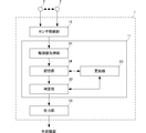
- FIG. 2 is a block diagram showing the configuration of the main part of the state determination device according to this example.
- the state determination device 1 of this example includes a control unit 11, a sensor connection unit 12, and an output unit 13.
- the control unit 11 controls the operation of the state determination device 1 main body.
- the control unit 11 also has a configuration for operating as the observed value acquiring unit 21, the determining unit 22, and the updating unit 23, and has a storage unit 24 that stores data necessary for operation.
- the storage unit 24 may be configured of a volatile memory or may be configured of a non-volatile memory. Details of the observation value acquisition unit 21, the determination unit 22, and the update unit 23 will be described later.
- the sensor connection unit 12 is connected to the magnetic sensor 2 installed in each parking frame 5.
- the magnetic sensor 2 connected to the sensor connection unit 12 is the magnetic sensor 2 installed in the parking frame 5 that determines whether the state determination device 1 is in the parked state or in the idle state.
- the sensor connection unit 12 may be configured to connect the magnetic sensor 2 by wire or may be configured to connect wirelessly.
- the magnetic sensor 2 inputs to the sensor connection unit 12 sensing signals obtained by sensing the strength of the magnetic field for each of three axes (X axis, Y axis, Z axis) orthogonal to each other.
- the sensor connection unit 12 corresponds to the input unit in the present invention.
- the output unit 13 outputs, for each parking frame 5 in which the magnetic sensor 2 connected to the sensor connection unit 12 is installed, the state (parked state or vacant state) determined for the parking frame 5 to an external device .
- This external device is, for example, a parking lot management device that manages a parking lot provided with a plurality of parking frames 5, and by managing whether the vehicle 7 is parked for each parking frame 5, the parking lot becomes full. It is determined whether or not it is in the state (the state in which the vehicle 7 is parked in all the parking spaces) (the parking space fullness determination is performed).
- the external device may be a device that controls the state of the lock plate (flap plate) provided in the parking frame 5.
- the lock plate said here is a member which restricts the leaving of the vehicle 7 from the parking frame 5.
- the lock plate is shifted to a state in which the delivery of the vehicle 7 from the parking frame 5 is restricted, and when the parking fee is settled, parking is performed. It is a member made to shift to the state of permitting the leaving of the vehicle 7 from the frame 5.
- the external device is not limited to the above-described type of device, and may be another device.
- the observation value acquisition unit 21 processes the input sensing signal to acquire an observation value each time a sensing signal is input from the magnetic sensor 2 connected to the sensor connection unit 12.
- the magnetic sensor 2 performs sensing in a cycle of several hundreds of msec (for example, 500 msec), and inputs a sensing signal at that time to the state determination device 1.
- the sensing signal input to the state determination device 1 by the magnetic sensor 2 includes the strength Hx of the magnetic field in the X-axis direction, the strength Hy of the magnetic field in the Y-axis direction, and the strength Hz of the magnetic field in the Z-axis direction. There is.
- the observation value acquisition unit 21 stores the acquired observation values in the storage unit 24 in a cumulative manner.
- the storage unit 24 is configured to classify and store the observation values acquired by the observation value acquisition unit 21 for each of the magnetic sensors 2 (that is, for each parking frame 5).
- the determination unit 22 determines the state of the parking frame 5 every time the state determination timing set in advance is reached.
- the state determination timing is set to an interval of several minutes (an interval of 1 to 5 minutes).
- the determination unit 22 calculates, as a determination value, the average value of the observation values acquired between the previous state determination timing and the current state determination. For example, when the sensing cycle of the magnetic sensor 2 is 500 msec and the cycle of the state determination timing is 3 minutes, the average value of 360 observed values acquired from the previous state determination timing to the current state determination is used. Calculated as a judgment value.
- the period of two state determination timings adjacent in time corresponds to the observation period in the present invention.
- the determination unit 22 determines that the parking frame 5 in which the magnetic sensor 2 is installed is It is determined that the status of is empty. Conversely, if the determination value is not within the first determination range, the determination unit 22 determines that the state of the parking frame 5 in which the magnetic sensor 2 is installed is in the parking state.
- the influence of the vehicle 7 parked in the parking frame 5 on the magnetic field observed by the magnetic sensor 2 varies depending on the structure of the vehicle 7 (the shape of the frame, the position of the engine, the positions of various electrical components, etc.).
- the influence of the vehicle 7 parked in the parking frame 5 on the magnetic field observed by the magnetic sensor 2 is in the case of increasing the observed value when the vehicle 7 is not parked in the parking frame 5
- the observation value of the magnetic sensor 2 may be reduced. Therefore, the observation value of the magnetic sensor 2 when the vehicle 7 is parked in the parking frame 5 may be larger than the observation value of the magnetic sensor 2 when the vehicle 7 is not parked in the parking frame 5 On the contrary, it may be smaller.
- the update unit 23 determines the determination reference value stored in the storage unit 24 as the determination value calculated this time. Update to Similarly to the first determination range, the second determination range is also determined based on the determination reference value stored in the storage unit 24 at that time. If the determination value calculated by the determination unit 22 is not within the second determination range, the update unit 23 does not update the determination reference value stored in the storage unit 24.
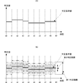
- FIG. 3A is a diagram showing a change of the determination reference value in this example
- FIG. 3B is a diagram showing a first determination range defined for the determination reference value shown in FIG.
- FIG. 2 is a diagram illustrating a determination range.
- T0 to t9 shown in FIG. 3 are the state determination timings described above.
- the determination reference value is updated by the updating unit 23.
- the range in which the absolute value of the difference from the determination reference value is within a is the first determination range
- the absolute value of the difference from the determination reference value is within b (a> b)
- the second range is the second determination range.
- the first determination range and the second determination range change with the change of the determination reference value.
- the determination reference value, the first determination range, and the second determination range will be supplemented.
- the strength of the magnetic field sensed by the magnetic sensor 2 when the vehicle 7 is not parked in the parking frame 5 and the strength of the magnetic field sensed by the magnetic sensor 2 when the vehicle 7 is parked in the parking frame 5 There is a relative size difference between When the vehicle 7 is not parked in the parking frame 5, the strength of the magnetic field sensed by the magnetic sensor 2 is set as the determination reference value. Therefore, when the vehicle 7 is parked in the parking frame 5, the vehicle 7 is parked by defining the first determination range according to the difference between the strength of the magnetic field sensed by the magnetic sensor 2 and the determination reference value. It can be determined whether the vehicle is parked in frame 5.
- the magnetic sensor 2 can be determined by determining the second determination range according to the difference between the strength of the magnetic field sensed by the magnetic sensor 2 and the determination reference value. It can be determined whether or not the strength of the magnetic field sensed by the vehicle is affected by the vehicle 7 present around the parking frame 5.
- the control unit 11 is configured by a hardware CPU, a memory, and other electronic circuits.
- the hardware CPU executes the state determination program according to the present invention
- the hardware CPU operates as the observation value acquisition unit 21, the determination unit 22, and the update unit 23.
- the memory has an area for expanding the state determination program according to the present invention, and an area for temporarily storing data generated at the time of execution of the state determination program, and is used as the storage unit 24 described above. It is a configuration having a storage area.
- the control unit 11 may be an LSI in which a hardware CPU, a memory, and the like are integrated.
- the hardware CPU is a computer that executes the state determination method according to the present invention.
- FIG. 4 is a flowchart showing the operation of the state determination device according to this example.
- the state determination device 1 performs the process illustrated in FIG. 4 in parallel for each parking frame 5 whose state is to be determined.
- the state determination device 1 repeatedly determines whether a sensing signal is input from the magnetic sensor 2 to the sensor connection unit 12 (s1) and whether it is a determination timing to determine the state of the parking frame 5 (s2). There is.
- the magnetic sensor 2 of this example senses the strength of the magnetic field at intervals of several hundreds of msec (for example, 500 msec), and inputs the sensing signal at that time to the sensor connection unit 12. Further, as described above, the state determination device 1 of this example sets the determination timing for determining the state of the parking frame 5 to an interval of several minutes (interval of 1 to 5 minutes).
- sensing time interval of the magnetic sensor 2 and the time interval of the determination timing shown here are merely examples, and are not limited to the above-described time intervals.
- the state determination device 1 determines that the sensing signal is input from the magnetic sensor 2 in s1, the state determination device 1 processes the sensing signal of the magnetic sensor 2 input this time to acquire the present observed value (s3).
- the storage unit 24 stores the observation value acquired this time.
- the sensing signal input to the state determination device 1 by the magnetic sensor 2 includes the strength Hx of the magnetic field in the X axis direction, the strength Hy of the magnetic field in the Y axis direction, and the strength of the magnetic field in the Z axis direction. Hz is included.
- the observation value acquisition unit 21 calculates and acquires observation values according to the following calculation formula.
- the state determination device 1 determines that it is the state determination timing in s2, the state determination device 1 calculates a determination value (s4).
- s4 the average value of the observed values acquired by processing the sensing signal of the magnetic sensor 2 input to the sensor connection unit 12 during the period from the previous state determination timing to the current state determination timing is calculated as the determination value .
- the current state determination timing is t5 shown in FIG. 3
- the determination unit 22 executes the process s4.
- the state determination device 1 determines whether the determination value calculated in s4 is a value within the first determination range set at that time (s5). In s5, if the absolute value of the difference between the determination value calculated in s4 and the determination reference value set at that time (determination value calculated in s4-determination reference value) is within a, then the state The determination device 1 determines that this determination value is a value within the first determination range. In other words, if the absolute value of the difference between the determination value calculated in s4 and the determination reference value set at that time exceeds a, the state determination device 1 determines that the determination value is the first determination. It is determined that the value is not within the range. The determination unit 22 executes the process s5.
- the state determination device 1 determines that the state is not within the first determination range in s5
- the state determination device 1 determines that the state of the parking frame 5 is the parking state (s6), and returns to s1.
- the determination unit 22 executes the process of s6.
- the state determination device 1 determines whether it is within the first determination range in s5, it determines whether the determination value calculated in s4 is a value within the second determination range set at that time (s7) .
- the absolute value of the difference between the judgment value calculated in s4 and the judgment reference value set at that time (the judgment value calculated in s4-judgment reference value) is within b (a> b) If it is, the state determination device 1 determines that this determination value is a value within the second determination range. In other words, if the absolute value of the difference between the determination value calculated in s4 and the determination reference value set at that time exceeds b, the state determination device 1 determines that the determination value is the second determination. It is determined that the value is not within the range.
- the update unit 23 executes the process s7.
- the state determination device 1 determines that the determination value is not within the second determination range in s7, the state determination device 1 determines that the state of the parking frame 5 is an idle state (s9), and returns to s1.
- the determination unit 22 executes the process s9.
- the state determination device 1 determines that the determination reference value stored in the storage unit 24 at that time is updated to the determination value calculated in s4.
- a reference value update process is performed (s8).
- the state determination device 1 determines that the state of the parking frame 5 is vacancy in s9 and returns to s1.
- the update unit 23 executes the process s8.
- the state determination device 1 determines the state of the parking frame 5 at s6 or s9, the state determination device 1 outputs the determination result to an external device connected to the output unit 13.
- the state determination device 1 updates the determination reference value when the determination value calculated in s4 is within the second determination range. That is, the state determination device 1 processes many of the sensing signals of the magnetic sensor 2 input to the sensor connection unit 12 during the period from the previous state determination timing to the current state determination timing.
- the determination reference value is updated. In other words, the judgment reference value is updated to an inappropriate value by the observation value influenced by the vehicle 7 parked in the parking frame 5 and the vehicle 7 present in the vicinity of the parking frame 5 Absent. Therefore, the state determination device 1 according to this example can properly perform the calibration of the determination reference value according to the aged deterioration of the magnetic sensor 2 and the environmental change around the installation location of the magnetic sensor 2 without human intervention. And increase the operation cost.
- the first determination range is determined based on the determination reference value at that time, and the observation value when the vehicle 7 is not parked in the parking frame 5 and the vehicle 7 It sets according to the difference with the observation value in the state parked in the parking frame 5. Since the state determination device 1 according to this example can properly perform calibration of the determination reference value according to the aged deterioration of the magnetic sensor 2 or the environmental change around the installation place of the magnetic sensor 2, the aged deterioration of the magnetic sensor 2 Also, it is possible to prevent the determination accuracy of the state of the parking frame 5 from being lowered due to the environmental change around the installation location of the magnetic sensor 2.
- the number of magnetic sensors 2 used to determine the state of the parking frame 5 can be one, so the cost for constructing the system can be reduced.
- the state of the parking frame 5 is determined depending on whether the determination value calculated in s4 is a value within the first determination range, and the determination value calculated in s4 is a value within the second determination range. If the values are to be updated, the order of the processes s5 to s9 may be changed in any way.
- the state determination device 1 according to another example will be described.
- the state determination device 1 according to this other example also has the configuration shown in FIG. 2 as in the above example.
- the state determination device 1 according to this another example differs from the above example in that the process shown in FIG. 5 is executed as the operation.
- the same step number (s **) is attached
- FIG. 5 is a flowchart showing the operation of the state determination device according to this other example.
- the state determination device 1 of this another example executes an operation in which the process of s8 shown in FIG. 4 is replaced with the process of s11 to s13. Specifically, when the state determination device 1 determines that the determination value calculated in s4 is within the second determination range in s7, the sensor connection is made in the period from the previous state determination timing to the current state determination timing. Among the observed values acquired by processing the sensing signal of the magnetic sensor 2 input to the unit 12, all the observed values within the second determination range are extracted (s11). In s11, within the second determination range from among the observed values acquired by processing the sensing signal of the magnetic sensor 2 input to the sensor connection unit 12 during the period from the previous state determination timing to the current state determination timing Is not removing observed values.
- the state determination device 1 calculates the update value of the determination reference value using the observed value extracted in s11 (s12).
- the update value of the determination reference value calculated in s12 is, for example, an average value of the observed values extracted in s11.
- the state determination device 1 updates the determination reference value stored in the storage unit 24 to the updated value calculated in s12 (s13), and determines that the state of the parking frame 5 is empty in s9.
- the updating unit 23 executes the processing of s11 to s13.
- the state determination device 1 is an observation value acquired by processing the sensing signal of the magnetic sensor 2 input to the sensor connection unit 12 in the period from the previous state determination timing to the current state determination timing. Even if the observation value is not within the second determination range, the update value of the determination reference value is calculated. In the processing according to s11 to s13, the average value of the observed values acquired by processing the sensing signal of the magnetic sensor 2 input to the sensor connection unit 12 during the period from the previous state determination timing to the current state determination timing is It is executed when it is within the second judgment range.
- observed values not used for calculating the updated value of the judgment reference value in s12 are, for example, observed values that are affected by noise caused by pulse noise or the like generated by the magnetic sensor 2 or vehicles that pass around the parking frame 5 It is highly likely that the observed values are affected by For this reason, the updated value of the determination reference value calculated in s12 is influenced by the observed value influenced by noise caused by pulse noise or the like generated by the magnetic sensor 2 and by the vehicle 7 passing around the parking frame 5 It is a value that suppresses the influence of observed values etc.
- the state determination device 1 is affected by the observed value affected by noise caused by pulse noise or the like generated by the magnetic sensor 2 and by the vehicle 7 passing around the parking frame 5 Since the influence of the observation value or the like can be sufficiently suppressed, the state of the parking frame 5 can be determined more accurately.
- the determination value calculated in the process according to s4 shown in FIGS. 4 and 5 is the value of the magnetic sensor 2 input to the sensor connection unit 12 in the period from the previous state determination timing to the current state determination timing.
- the sensing signal may be processed to be the median of the acquired observed values, or it may be the root mean square of the observed values acquired during this period.
- the update value of the determination reference value calculated in the process according to s12 shown in FIG. 5 may be the median of the observed values extracted in s11, or the root mean square of the observed values acquired in this period. It is also good.
- the first determination range and the second determination range are ranges determined centering on the determination reference value, but the first determination range and the second determination range are not shown in FIG. As shown in (B) and (B), the determination reference value may be shifted from the center and defined as a range.
- the magnetic sensor 2 is a triaxial magnetic sensor, but may be a biaxial magnetic sensor 2.
- the sensor that senses the observation characteristic of the observation target is not limited to the magnetic sensor 2 shown in the above example, but may be another type of sensor such as a pressure sensor or a temperature sensor.
- a room for example, a clean room
- the pressure of the room is sensed by the pressure sensor as observation characteristics. It can be used as a state determination device to determine whether or not.
- this invention targets a room (for example, a clean room) where the room temperature is managed as observation target, senses the room temperature of this room with the temperature sensor as an observation characteristic, and is open state by forgetting to close the door or window It can also be used as a state determination device to determine whether or not.
- An observation value acquisition unit (21) that processes the sensing signal input to the input unit (12) to acquire an observation value;
- a determination unit (22) that determines whether the state of the observation target (5) is the first state or the second state based on the determination value calculated using the observation value;
- An updating unit (23) for updating a determination reference value used by the determination unit (22) to determine the state of the observation target (5);
- the determination unit (22) determines whether the state of the observation target (5) is in the first state depending on whether the determination value is a value within a first determination range determined based on the determination reference value.
- the updating unit (23) updates the determination reference value if the determination value is a value within a second determination range defined within the first determination range, and conversely, the determination value is the second determination State determination unit (1) which does not update the said judgment reference value if it is not a value in a range.
Landscapes
- Physics & Mathematics (AREA)
- General Physics & Mathematics (AREA)
- Engineering & Computer Science (AREA)
- Manufacturing & Machinery (AREA)
- Life Sciences & Earth Sciences (AREA)
- General Life Sciences & Earth Sciences (AREA)
- Geophysics (AREA)
- Traffic Control Systems (AREA)
- Geophysics And Detection Of Objects (AREA)
Abstract
観測値取得部(21)が入力された磁気センサ(2)のセンシング信号を処理して観測値を取得する。判定部(22)は観測値を用いて算出した判定値が判定基準値に基づいて定めた第1判定範囲内の値であるかどうかにより、観測対象が第1の状態であるか、第2の状態であるかを判定する。更新部(23)は、判定値が第1判定範囲内に定めた第2判定範囲内の値であれば判定基準値を更新し、反対に判定値が第2判定範囲内の値でなければ判定基準値を更新しない。
Description
この発明は、観測対象の観測特性をセンシングしたセンサのセンシング信号を処理して、観測対象の状態を判定する技術に関する。
従来、観測対象の観測特性をセンシングしたセンサのセンシング信号を処理して観測対象の状態を判定する装置があった。観測対象とは、実世界の現象の抽象(人、物、事象等)であり、観測特性とは、実センサで観測する観測対象の特性である。
例えば、特許文献1には、車両を駐車する駐車スペースに、車両が駐車されているかどうかを磁気センサを用いて検出する装置が記載されている。この特許文献1に記載された装置は、駐車スペースに、2軸、または3軸の磁気センサを複数設置し、2つの磁気センサ間において、軸毎に検出された磁気出力(センサ出力)の差分を算出し、これらの差分の合成値を算出する。例えば、特許文献1に記載された装置は、磁気センサが3軸(X軸、Y軸、Z軸)である場合、X軸差分、Y軸差分、およびZ軸差分を算出する。X軸差分は、一方の磁気センサのX軸のセンサ出力X1と他方の磁気センサのX軸のセンサ出力X2との差分(X1-X2)である。Y軸差分は、一方の磁気センサのY軸のセンサ出力Y1と他方の磁気センサのY軸のセンサ出力Y2との差分(Y1-Y2)である。Z軸差分は、一方の磁気センサのZ軸のセンサ出力Z1と他方の磁気センサのZ軸のセンサ出力Z2との差分(Z1-Z2)である。この特許文献1に記載された装置は、磁気センサの各軸のセンサ出力の差分の二乗和((X1-X2)2+(Y1-Y2)2+(Z1-Z2)2)の平方根を、各軸の差分の合成値として算出し、算出した各軸の差分の合成値が予め定めた閾値Aを超えていれば、車両が駐車スペースにあると判定する構成である。
特許文献1に記載された装置においては、センサが2軸、または3軸の磁気センサであり、観測対象が駐車スペースであり、観測特性が磁界の強度である。また、特許文献1に記載された装置は、観測対象である駐車スペースの状態として、車両が駐車されている駐車状態であるか、車両が駐車されていない空き状態であるかを判定する。
しかしながら、観測対象の観測特性をセンシングしたセンサのセンシング信号を処理して観測対象の状態を判定する装置においては、判定精度の低下による誤判定を抑えるために、センサの経年劣化等に応じて観測対象の状態を判定するのに使用する値等のキャリブレーションが必要であった。例えば、特許文献1に記載された装置であれば、駐車スペースの状態の判定精度の低下を抑えるために、磁気センサの経年劣化に応じて閾値A等のキャリブレーションが必要である。
従来、観測対象の状態を判定するのに使用する値等のキャリブレーションは、作業者をセンサの設置場所に派遣して行っていた。このため、このキャリブレーションは、多大な人手を要する作業であり、運用コストを増大させていた。
この発明の目的は、センサの経年劣化にともなう観測対象の状態の判定精度の低下を防止し、且つ運用コストが増大するのを抑えることができる技術を提供することにある。
この発明の状態判定ユニットは、上記目的を達するために、以下のように構成している。
入力部には、観測対象の観測特性をセンシングしたセンサのセンシング信号が入力される。観測対象とは、実世界の現象の抽象(人、物、事象等)であり、観測特性とは、実センサで観測する観測対象の特性である。
また、判定部は、センシング信号に基づいて算出した判定値により、観測対象の状態が第1の状態であるか、第2の状態であるかを判定する。更新部は、判定部が観測対象の状態を判定するのに用いる判定基準値を更新する。この判定部は、判定値が判定基準値に基づいて定めた第1判定範囲内の値であるかどうかによって、観測対象の状態が第1の状態であるか、第2の状態であるかを判定する。また、更新部は、判定値が第1判定範囲内に定めた第2判定範囲内の値であれば、判定基準値を更新し、反対に判定値が第2判定範囲内の値でなければ、判定基準値を更新しない。
この構成によれば、センサの経年劣化に対する判定基準値の更新(キャリブレーション)が人手をかけることなく、自動的に行える。また、判定基準値は、観測対象周辺における環境変化による影響を受けることなく更新できる。したがって、センサの経年劣化にともなう観測対象の状態の判定精度の低下を防止でき、且つ運用コストが増大するのを抑えることができる。
また、入力部に入力されたセンシング信号を処理して観測値を取得する観測値取得部を備え、この観測値取得部が時間的に連続する観測期間に取得した複数の観測値を用いて判定値を算出する構成にしてもよい。観測値は、センサによってセンシングされた観測特性の計測値であり、例えばセンサが磁気センサであれば、観測値は磁界(地場)の大きさであり、センサが温度センサであれば、観測値は温度であり、センサが圧力センサであれば、観測値は気圧である。
また、判定値は、観測値取得部が時間的に連続する観測期間に取得した複数の観測値を用いて算出するのがよい。例えば、観測期間に取得した複数の観測値の平均値を判定値にしてもよいし、観測期間に取得した複数の観測値の中央値を判定値にしてもよいし、複数の観測値の二乗平均平方根にしてもよいし、これら以外の手法で判定値を算出し、決定してもよい。
このように構成すれば、判定値の算出において、センサで発生したパルスノイズ等によるノイズの影響を抑えることができる。その結果、観測対象の状態の判定においても、センサで発生したパルスノイズ等によるノイズの影響を抑えることができる。
また、更新部は、判定値が第2判定範囲内の値であれば、判定基準値を判定値に更新すればよい。このように構成すれば、観測対象の状態の判定精度を低下させることなく、判定基準値を簡単な処理で更新できる。
また、更新部は、判定値が第2判定範囲内の値であれば、観測期間に取得した複数の観測値の中から、第2判定範囲内の値である観測値を抽出し、判定基準値を、ここで抽出した観測値によって算出した値、例えば平均値、に更新してもよい。このように構成すれば、センサで発生したパルスノイズや、観測対象周辺における一時的な環境変化等の影響を抑えた判定基準値に更新できる。
また、状態判定ユニットと、この状態判定ユニットに対して、観測対象の観測特性をセンシングしたセンシング信号を入力するセンサと、を備える検知装置として構成してもよい。例えば、観測対象を、車両を駐車する駐車枠とし、センサを、観測特性として磁場をセンシングする磁気センサにすることで、駐車枠の状態が、車両が駐車されている駐車状態であるか、車両が駐車されていない空き状態であるかを判定できる。
この発明によれば、センサの経年劣化にともなう観測対象の状態の判定精度の低下を防止し、且つ運用コストが増大するのを抑えることができる。
以下、この発明の実施形態について説明する。
<1.適用例>
この発明が適用される場面の1つの例を説明する。図1は、この発明の1つの実施形態である状態判定装置の適用場面例を説明する図である。この例における状態判定装置1が、この発明にかかる状態判定ユニットに相当する構成である。この例にかかる状態判定装置1は、図1に示す駐車枠5(5a、5b、5c)毎に、車両7が駐車されている駐車状態であるか、車両7が駐車されていない空き状態であるかを判定する。図1に例示している駐車枠5(5a、5b、5c)は3つであるが、駐車枠5の個数は1つ以上であればいくつであってもよい。また、図1では、駐車枠5a、5cは車両7が駐車されていない空き状態を示しており、駐車枠5bは車両7が駐車されている駐車状態を示している。
この発明が適用される場面の1つの例を説明する。図1は、この発明の1つの実施形態である状態判定装置の適用場面例を説明する図である。この例における状態判定装置1が、この発明にかかる状態判定ユニットに相当する構成である。この例にかかる状態判定装置1は、図1に示す駐車枠5(5a、5b、5c)毎に、車両7が駐車されている駐車状態であるか、車両7が駐車されていない空き状態であるかを判定する。図1に例示している駐車枠5(5a、5b、5c)は3つであるが、駐車枠5の個数は1つ以上であればいくつであってもよい。また、図1では、駐車枠5a、5cは車両7が駐車されていない空き状態を示しており、駐車枠5bは車両7が駐車されている駐車状態を示している。
各駐車枠5には、その内側に、磁気センサ2が1つ設置されている。この例では、磁気センサ2は、互いに直交する3軸(X軸、Y軸、Z軸)方向のそれぞれについて、磁界(地場)の強さをセンシングする3軸の磁気センサである。磁気センサ2は、各軸方向の磁界の強さをセンシングしたセンシング信号を状態判定装置1に入力する。磁気センサ2は、駐車枠5内であれば、駐車枠5の中心から離れた場所に設置してもよい(図1に示す例は、磁気センサ2を駐車枠5の略中心に設置している。)。この例では、磁気センサ2が、この発明で言うセンサに相当する。
また、この発明で言う、観測対象とは、実世界の現象の抽象(人、物、事象等)であり、観測特性とは、実センサで観測する観測対象の特性である。この例では、駐車枠5が、観測対象であり、各軸方向の磁界の強さが観測特性である。
なお、この発明にかかる検知装置の1つの例が、この例における状態判定装置1、およびこの状態判定装置1に接続されている磁気センサ2によって構成される。
状態判定装置1は、駐車枠5毎に、その駐車枠5内に設置されている磁気センサ2のセンシング信号を処理して観測値を取得する。具体的には、状態判定装置1は、磁気センサ2によってセンシングされた、X軸方向の磁界の強さがHx、Y軸方向の磁界の強さがHy、Z軸方向の磁界の強さがHzであるときの観測値を、
観測値=((Hx)2+(Hy)2+(Hz)2)1/2
により算出する。ただし、Hx、Hy、およびHzは、略同じタイミングでセンシングされた磁界の強さである。
観測値=((Hx)2+(Hy)2+(Hz)2)1/2
により算出する。ただし、Hx、Hy、およびHzは、略同じタイミングでセンシングされた磁界の強さである。
状態判定装置1は、この観測値を用いて判定値を算出する。この例では、判定値は、ある期間に取得した観測値の平均値ある。状態判定装置1は、判定値により、駐車枠5が駐車状態であるか、空き状態であるかを判定する。この例では、駐車状態がこの発明で言う第1の状態であり、空き状態がこの発明で言う第2の状態である。状態判定装置1は、判定基準値を基準にして第1判定範囲を定めている。状態判定装置1は、判定値が、第1判定範囲内でなければ、駐車枠5の状態を駐車状態であると判定する。状態判定装置1は、反対に、判定値が第1判定範囲内であれば、駐車枠5の状態を空き状態であると判定する。
また、状態判定装置1は、第1判定範囲内に第2判定範囲を定めている。すなわち、第2判定範囲は、第1判定範囲の一部分である。状態判定装置1は、判定値が第2判定範囲内であるとき判定基準値を更新し、判定値が第2判定範囲内でないとき判定基準値を更新しない。
この状態判定装置1は、判定基準値を基準にして定められる第1判定範囲を適正に設定することにより、駐車枠5の状態が駐車状態であるか、空き状態であるかを精度よく判定できる。また、状態判定装置1は、第2判定範囲を適正に設定することにより、駐車枠5内、および駐車枠5の周辺に車両7が存在していないときの観測値を用いて、判定基準値を更新(キャリブレーション)することができる。すなわち、状態判定装置1は、駐車枠5内、および駐車枠5周辺に位置する車両7に影響されることなく、判定基準値のキャリブレーションが行えるので、磁気センサ2の経年劣化による判定精度の低下を抑えられる。また、状態判定装置1は、判定基準値のキャリブレーションを人手をかけることなく自動的に行うので、運用コストの増大についても抑えられる。
<2.構成例>
図2は、この例にかかる状態判定装置の主要部の構成を示すブロック図である。この例の状態判定装置1は、制御ユニット11と、センサ接続部12と、出力部13と、を備えている。制御ユニット11は、状態判定装置1本体の動作を制御する。また、制御ユニット11は、観測値取得部21、判定部22、および更新部23として動作するための構成を有しているとともに、動作時に必要なデータを記憶する記憶部24を有している。記憶部24は、揮発性のメモリで構成されていてもよいし、不揮発性のメモリで構成されていてもよい。観測値取得部21、判定部22、および更新部23の詳細については、後述する。
図2は、この例にかかる状態判定装置の主要部の構成を示すブロック図である。この例の状態判定装置1は、制御ユニット11と、センサ接続部12と、出力部13と、を備えている。制御ユニット11は、状態判定装置1本体の動作を制御する。また、制御ユニット11は、観測値取得部21、判定部22、および更新部23として動作するための構成を有しているとともに、動作時に必要なデータを記憶する記憶部24を有している。記憶部24は、揮発性のメモリで構成されていてもよいし、不揮発性のメモリで構成されていてもよい。観測値取得部21、判定部22、および更新部23の詳細については、後述する。
センサ接続部12は、各駐車枠5に設置された磁気センサ2が接続される。センサ接続部12に接続される磁気センサ2は、この状態判定装置1が駐車状態であるか、空き状態であるかを判定する駐車枠5に設置された磁気センサ2である。センサ接続部12は、磁気センサ2を有線で接続する構成であってもよいし、無線で接続する構成であってもよい。磁気センサ2は、互いに直交する3軸(X軸、Y軸、Z軸)のそれぞれについて磁界の強さをセンシングしたセンシング信号をセンサ接続部12に入力する。センサ接続部12が、この発明で言う入力部に相当する。
出力部13は、センサ接続部12に接続されている磁気センサ2が設置されている駐車枠5毎に、その駐車枠5について判定した状態(駐車状態、または空き状態)を外部機器に出力する。この外部機器は、例えば複数の駐車枠5が設けられた駐車場を管理する駐車場管理装置であり、駐車枠5毎に車両7が駐車されているかどうかを管理することにより、駐車場が満車状態(全ての駐車枠に車両7が駐車されている状態)であるかどうかを判定する(駐車場の満空判定を行う。)。また、外部機器は、駐車枠5に設けられているロック板(フラップ板)の状態を制御する装置であってもよい。ここで言うロック板とは、駐車枠5からの車両7の出庫を制限する部材である。より具体的には、ロック板は、駐車枠5に車両7が駐車されると、駐車枠5からの車両7の出庫を制限する状態に移行させられ、駐車料金の精算が行われると、駐車枠5からの車両7の出庫を許容する状態に移行させられる部材である。
なお、外部機器は、上記した種類の機器に限らず、他の機器であってもよい。
次に、この例の制御ユニット11が備える、観測値取得部21、判定部22、更新部23、および記憶部24について説明する。観測値取得部21は、センサ接続部12に接続されている磁気センサ2からセンシング信号が入力される毎に、入力されたセンシング信号を処理して観測値を取得する。磁気センサ2は、数100msec(例えば、500msec)周期でセンシングを行い、そのときのセンシング信号を状態判定装置1に入力する。磁気センサ2が状態判定装置1に入力するセンシング信号には、X軸方向の磁界の強さHx、Y軸方向の磁界の強さHy、およびZ軸方向の磁界の強さHzが含まれている。観測値取得部21が取得する観測値は、
観測値=((Hx)2+(Hy)2+(Hz)2)1/2
である。観測値取得部21は、取得した観測値を記憶部24に蓄積的に記憶させる。記憶部24は、観測値取得部21が取得した観測値を、磁気センサ2毎(すなわち駐車枠5毎)に、分類して記憶する構成である。
観測値=((Hx)2+(Hy)2+(Hz)2)1/2
である。観測値取得部21は、取得した観測値を記憶部24に蓄積的に記憶させる。記憶部24は、観測値取得部21が取得した観測値を、磁気センサ2毎(すなわち駐車枠5毎)に、分類して記憶する構成である。
判定部22は、予め設定されている状態判定タイミングになる毎に、駐車枠5の状態を判定する。この例では、状態判定タイミングは、数分間隔(1~5分間隔)に設定されている。この例では、判定部22は、前回の状態判定タイミングから今回の状態判定までの間に取得した観測値の平均値を判定値として算出する。例えば、磁気センサ2のセンシング周期が500msecであり、状態判定タイミングの周期が3分である場合、前回の状態判定タイミングから今回の状態判定までの間に取得した360個の観測値の平均値を判定値として算出する。時間的に隣接する2つの状態判定タイミングの期間が、この発明で言う観測期間に相当する。
判定部22は、算出した判定値が、その時点において記憶部24に記憶している判定基準値に基づいて定めた第1判定範囲内であれば、磁気センサ2が設置されている駐車枠5の状態が空き状態であると判定する。判定部22は、反対に、判定値が第1判定範囲内でなければ、磁気センサ2が設置されている駐車枠5の状態が駐車状態であると判定する。駐車枠5に駐車された車両7が磁気センサ2によって観測される磁界に与える影響は、車両7の構造(フレームの形状、エンジンの位置、各種電装部品の位置等)によってさまざまである。具体的には、駐車枠5に駐車された車両7が磁気センサ2によって観測される磁界に与える影響は、駐車枠5に車両7が駐車されていないときの観測値を増大させる方向である場合もあれば、逆に駐車枠5に車両7が駐車されていないときの磁気センサ2の観測値を減少させる方向である場合もある。したがって、駐車枠5に車両7が駐車されているときの磁気センサ2の観測値は、駐車枠5に車両7が駐車されていないときの磁気センサ2の観測値に比べて大きくなることもあれば、逆に小さくなることもある。
更新部23は、判定部22が算出した判定値が第1判定範囲内に定めた第2判定範囲内であれば、記憶部24に記憶している判定基準値を、今回算出された判定値に更新する。第2判定範囲も、第1判定範囲と同様に、その時点において記憶部24に記憶している判定基準値を基準にして定めている。更新部23は、判定部22が算出した判定値が第2判定範囲内でなければ、記憶部24に記憶している判定基準値を更新しない。
図3(A)は、この例における判定基準値の変化を示す図であり、図3(B)は、図3(A)に示す判定基準値に対して定められる第1判定範囲、および第2判定範囲を示す図である。図3に示すt0~t9は、上述した状態判定タイミングである。上述したように、判定基準値は、更新部23によって更新される。図3(B)に示す例は、判定基準値との差分の絶対値がa以内である範囲が第1判定範囲であり、判定基準値との差分の絶対値がb(a>b)以内である範囲が第2判定範囲である。図3(B)に示すように、判定基準値の変化にともなって、第1判定範囲、および第2判定範囲が変化する。
判定基準値、第1判定範囲、および第2判定範囲について補足しておく。車両7が駐車枠5に駐車されていないときに、磁気センサ2によってセンシングされる磁界の強さと、車両7が駐車枠5に駐車されているときに、磁気センサ2によってセンシングされる磁界の強さとの間には、比較的大きさ差異がある。車両7が駐車枠5に駐車されていないときに、磁気センサ2によってセンシングされる磁界の強さを判定基準値に設定する。したがって、車両7が駐車枠5に駐車されているときに、磁気センサ2によってセンシングされる磁界の強さと、判定基準値との差異に応じて第1判定範囲を定めることによって、車両7が駐車枠5に駐車されているかどうかを判定することができる。
また、車両7が駐車枠5周辺に存在しているとき(例えば、隣接する駐車枠5に車両7が駐車されているとき)も、磁気センサ2によってセンシングされる磁界の強さと、判定基準値との間に差異が生じる。この差異は、車両7が駐車枠5に駐車されているときに生じる差異よりも小さい。したがって、車両7が駐車枠5周辺に存在しているときに、磁気センサ2によってセンシングされる磁界の強さと、判定基準値との差異に応じて第2判定範囲を定めることによって、磁気センサ2によってセンシングされる磁界の強さが、駐車枠5周辺に存在している車両7の影響を受けているかどうかを判定することができる。
制御ユニット11は、ハードウェアCPU、メモリ、その他の電子回路によって構成されている。ハードウェアCPUが、この発明にかかる状態判定プログラムを実行したときに、観測値取得部21、判定部22、および更新部23として動作する。また、メモリは、この発明にかかる状態判定プログラムを展開する領域や、この状態判定プログラムの実行時に生じたデータ等を一時記憶する領域を有しているとともに、上述した記憶部24として利用される記憶領域を有する構成である。制御ユニット11は、ハードウェアCPU、メモリ等を一体化したLSIであってもよい。また、ハードウェアCPUが、この発明にかかる状態判定方法を実行するコンピュータである。
<3.動作例>
図4は、この例にかかる状態判定装置の動作を示すフローチャートである。図4では、ある1つの駐車枠5に対する処理を示している。状態判定装置1は、図4に示す処理を、状態を判定する対象の駐車枠5毎に並行して行う。
図4は、この例にかかる状態判定装置の動作を示すフローチャートである。図4では、ある1つの駐車枠5に対する処理を示している。状態判定装置1は、図4に示す処理を、状態を判定する対象の駐車枠5毎に並行して行う。
状態判定装置1は、磁気センサ2からセンシング信号がセンサ接続部12に入力されたかどうか(s1)、および駐車枠5の状態を判定する判定タイミングであるかどうか(s2)、について繰り返し判定している。この例の磁気センサ2は、上述したように数100msec(例えば、500msec)間隔で磁界の強さをセンシングし、そのときのセンシング信号をセンサ接続部12に入力している。また、この例の状態判定装置1は、上述したように駐車枠5の状態を判定する判定タイミングを数分間隔(1~5分間隔)に設定している。
なお、ここで示した磁気センサ2のセンシング時間間隔、および判定タイミングの時間間隔は、あくまでも例示であり、上記した時間間隔に限定されるものではない。
状態判定装置1は、s1で磁気センサ2からセンシング信号が入力されたと判定すると、今回入力された磁気センサ2のセンシング信号を処理して今回の観測値を取得する(s3)。また、s3では、今回取得した観測値を記憶部24に記憶させる。上述したように、磁気センサ2が状態判定装置1に入力するセンシング信号には、X軸方向の磁界の強さHx、Y軸方向の磁界の強さHy、およびZ軸方向の磁界の強さHzが含まれている。観測値取得部21は、以下の算出式で観測値を算出し、取得する。
観測値=((Hx)2+(Hy)2+(Hz)2)1/2
観測値取得部21が、s3にかかる処理を実行する。状態判定装置1は、s3にかかる処理を完了すると、s1に戻る。
観測値取得部21が、s3にかかる処理を実行する。状態判定装置1は、s3にかかる処理を完了すると、s1に戻る。
また、状態判定装置1は、s2で状態判定タイミングであると判定すると、判定値を算出する(s4)。s4では、前回の状態判定タイミングから今回の状態判定タイミングまでの期間に、センサ接続部12に入力された磁気センサ2のセンシング信号を処理して取得した観測値の平均値を判定値として算出する。例えば、今回の状態判定タイミングが図3に示したt5である場合、t4~t5の期間に、センサ接続部12に入力された磁気センサ2のセンシング信号を処理して取得した観測値の平均値を判定値として算出する。判定部22が、s4にかかる処理を実行する。
状態判定装置1は、s4で算出した判定値がその時点で設定されている第1判定範囲内の値であるかどうかを判定する(s5)。s5では、s4で算出した判定値と、その時点で設定されている判定基準値との差分(s4で算出した判定値-判定基準値)の絶対値がa以内の大きさであれば、状態判定装置1は、この判定値が第1判定範囲内の値であると判定する。言い換えれば、s4で算出した判定値と、その時点で設定されている判定基準値との差分の絶対値がaを超える大きさであれば、状態判定装置1は、この判定値が第1判定範囲内の値でないと判定する。判定部22が、s5にかかる処理を実行する。
状態判定装置1は、s5で第1判定範囲内でないと判定すると、駐車枠5の状態を駐車状態と判定し(s6)、s1に戻る。判定部22が、s6にかかる処理を実行する。
状態判定装置1は、s5で第1判定範囲内であると判定すると、s4で算出した判定値がその時点で設定されている第2判定範囲内の値であるかどうかを判定する(s7)。s7では、s4で算出した判定値と、その時点で設定されている判定基準値との差分(s4で算出した判定値-判定基準値)の絶対値がb(a>b)以内の大きさであれば、状態判定装置1は、この判定値が第2判定範囲内の値であると判定する。言い換えれば、状態判定装置1は、s4で算出した判定値と、その時点で設定されている判定基準値との差分の絶対値がbを超える大きさであれば、この判定値が第2判定範囲内の値でないと判定する。更新部23が、s7にかかる処理を実行する。
状態判定装置1は、s7で判定値が第2判定範囲内でないと判定すると、駐車枠5の状態を空き状態と判定し(s9)、s1に戻る。判定部22が、s9にかかる処理を実行する。
また、状態判定装置1は、s7で判定値が第2判定範囲内であると判定すると、その時点で記憶部24に記憶している判定基準値を、s4で算出した判定値に更新する判定基準値更新処理を行う(s8)。また、状態判定装置1は、s8にかかる判定基準値更新処理を行うと、s9で駐車枠5の状態を空き状態と判定し、s1に戻る。更新部23が、s8にかかる処理を実行する。
なお、状態判定装置1は、s6、またはs9で駐車枠5の状態を判定すると、判定結果を出力部13に接続されている外部機器に出力する。
このように、この例にかかる状態判定装置1は、s4で算出した判定値が第2判定範囲内であるとき、判定基準値を更新する。すなわち、状態判定装置1は、前回の状態判定タイミングから今回の状態判定タイミングまでの期間に、センサ接続部12に入力された磁気センサ2のセンシング信号を処理して取得した観測値の多くが、駐車枠5に駐車されている車両7、および駐車枠5周辺に存在している車両7の影響を受けていない観測値であったときに、判定基準値を更新する。言い換えれば、判定基準値が、駐車枠5に駐車されている車両7、および駐車枠5周辺に存在している車両7の影響を受けた観測値によって、不適正な値に更新されることがない。このため、この例にかかる状態判定装置1は、磁気センサ2の経年劣化や、磁気センサ2の設置場所周辺の環境変化に応じた判定基準値のキャリブレーションを人手をかけることなく適正に行えるので、運用コストが増大するのを抑えることができる。
また、上述したように、第1判定範囲は、その時点の判定基準値に基づいて定めており、且つ車両7が駐車枠5に駐車されていない状態であるときの観測値と、車両7が駐車枠5に駐車されている状態であるときの観測値との差に応じて設定している。この例にかかる状態判定装置1は、磁気センサ2の経年劣化や、磁気センサ2の設置場所周辺の環境変化に応じた判定基準値のキャリブレーションが適正に行えることから、磁気センサ2の経年劣化や、磁気センサ2の設置場所周辺の環境変化により駐車枠5の状態の判定精度が低下するのを防止できる。
また、この例では、駐車枠5の状態を判定するために用いる磁気センサ2を1つにできるので、システムの構築にかかるコストも抑えられる。
なお、s4で算出した判定値が第1判定範囲内の値であるかどうかによって駐車枠5の状態を判定し、且つs4で算出した判定値が第2判定範囲内の値であれば判定基準値を更新するものであれば、s5~s9にかかる処理の順番は、どのように変更してもよい。
<4.変形例>
別の例にかかる状態判定装置1について説明する。この別の例にかかる状態判定装置1も、上記の例と同様に図2に示す構成である。この別の例にかかる状態判定装置1は、その動作として図5に示す処理を実行する点で、上記の例と異なる。図5では、図4と同じ処理については、同じステップ番号(s**)を付している。図5は、この別の例にかかる状態判定装置の動作を示すフローチャートである。
別の例にかかる状態判定装置1について説明する。この別の例にかかる状態判定装置1も、上記の例と同様に図2に示す構成である。この別の例にかかる状態判定装置1は、その動作として図5に示す処理を実行する点で、上記の例と異なる。図5では、図4と同じ処理については、同じステップ番号(s**)を付している。図5は、この別の例にかかる状態判定装置の動作を示すフローチャートである。
この別の例の状態判定装置1は、図4に示したs8にかかる処理をs11~s13にかかる処理に置き換えた動作を実行する。具体的には、状態判定装置1は、s7において、s4で算出した判定値が第2判定範囲内であると判定すると、前回の状態判定タイミングから今回の状態判定タイミングまでの期間に、センサ接続部12に入力された磁気センサ2のセンシング信号を処理して取得した観測値の中から、第2判定範囲内である観測値を全て抽出する(s11)。s11では、前回の状態判定タイミングから今回の状態判定タイミングまでの期間に、センサ接続部12に入力された磁気センサ2のセンシング信号を処理して取得した観測値の中から、第2判定範囲内でない観測値を取り除いている。
状態判定装置1は、s11で抽出した観測値を用いて、判定基準値の更新値を算出する(s12)。s12で算出する判定基準値の更新値は、例えばs11で抽出した観測値の平均値である。状態判定装置1は、記憶部24に記憶している判定基準値をs12で算出した更新値に更新し(s13)、s9で駐車枠5の状態を空き状態であると判定する。更新部23が、このs11~s13にかかる処理を実行する。
このように、状態判定装置1は、前回の状態判定タイミングから今回の状態判定タイミングまでの期間に、センサ接続部12に入力された磁気センサ2のセンシング信号を処理して取得した観測値であっても、第2判定範囲内でない観測値を用いないで、判定基準値の更新値を算出する。s11~s13にかかる処理は、前回の状態判定タイミングから今回の状態判定タイミングまでの期間に、センサ接続部12に入力された磁気センサ2のセンシング信号を処理して取得した観測値の平均値が第2判定範囲内であったときに実行される。したがって、s12での判定基準値の更新値の算出に用いない観測値は、例えば磁気センサ2で発生したパルスノイズ等によるノイズの影響を受けた観測値や、駐車枠5周辺を通過した車両7の影響を受けた観測値等である可能性が高い。このため、s12で算出される判定基準値の更新値は、磁気センサ2で発生したパルスノイズ等によるノイズの影響を受けた観測値や、駐車枠5周辺を通過した車両7の影響を受けた観測値等の影響を抑えた値になる。すなわち、状態判定装置1は、判定基準値のキャリブレーションにおいて、磁気センサ2で発生したパルスノイズ等によるノイズの影響を受けた観測値や、駐車枠5周辺を通過した車両7の影響を受けた観測値等の影響を十分に抑えることができるので、駐車枠5の状態をより精度よく判定することができる。
また、図4、および図5に示したs4にかかる処理において算出する判定値は、前回の状態判定タイミングから今回の状態判定タイミングまでの期間に、センサ接続部12に入力された磁気センサ2のセンシング信号を処理して取得した観測値の中央値にしてもよいし、この期間に取得した観測値の二乗平均平方根にしてもよい。
また、図5に示したs12にかかる処理において算出する判定基準値の更新値も、s11で抽出した観測値の中央値にしてもよいし、この期間に取得した観測値の二乗平均平方根にしてもよい。
また、上記の例では、第1判定範囲、および第2判定範囲は、判定基準値を中心にして定めた範囲であったが、第1判定範囲、および第2判定範囲は、図5(A)、(B)に示すように、判定基準値を中心からずらして定めた範囲にしてもよい。
また、上記の例では、磁気センサ2は、3軸の磁気センサであるとしたが、2軸の磁気センサ2であってもよい。
また、観測対象の観測特性をセンシングするセンサは、上記の例で示した磁気センサ2に限らず、圧力センサ、温度センサ等の他の種類のセンサであってもよい。例えば、この発明は、室圧が管理されている部屋(例えば、クリーンルーム)を観測対象とし、この部屋の圧力を観測特性として圧力センサでセンシングし、扉や窓等が閉め忘れによって開放状態であるかどうかを判定する状態判定装置として利用できる。また、この発明は、室温が管理されている部屋(例えば、クリーンルーム)を観測対象とし、この部屋の室温を観測特性として温度センサでセンシングし、扉や窓等が閉め忘れによって開放状態であるかどうかを判定する状態判定装置としても利用できる。
なお、この発明は、上記実施形態そのままに限定されるものではなく、実施段階ではその要旨を逸脱しない範囲で構成要素を変形して具体化できる。また、上記実施形態に開示されている複数の構成要素の適宜な組み合せにより種々の発明を形成できる。例えば、実施形態に示される全構成要素から幾つかの構成要素を削除してもよい。さらに、異なる実施形態に亘る構成要素を適宜組み合せてもよい。
さらに、この発明にかかる構成と上述した実施形態にかかる構成との対応関係は、以下の付記のように記載できる。
<付記>
観測対象(5)の観測特性をセンシングしたセンサ(2)のセンシング信号が入力される入力部(12)と、
前記入力部(12)に入力された前記センシング信号を処理して観測値を取得する観測値取得部(21)と、
前記観測値を用いて算出した判定値により、前記観測対象(5)の状態が第1の状態であるか、第2の状態であるかを判定する判定部(22)と、
前記判定部(22)が前記観測対象(5)の状態を判定するのに用いる判定基準値を更新する更新部(23)と、を備え、
前記判定部(22)は、前記判定値が前記判定基準値に基づいて定めた第1判定範囲内の値であるかどうかによって、前記観測対象(5)の状態が第1の状態であるか、第2の状態であるかを判定し、
前記更新部(23)は、前記判定値が前記第1判定範囲内に定めた第2判定範囲内の値であれば、前記判定基準値を更新し、反対に前記判定値が前記第2判定範囲内の値でなければ、前記判定基準値を更新しない、状態判定ユニット(1)。
観測対象(5)の観測特性をセンシングしたセンサ(2)のセンシング信号が入力される入力部(12)と、
前記入力部(12)に入力された前記センシング信号を処理して観測値を取得する観測値取得部(21)と、
前記観測値を用いて算出した判定値により、前記観測対象(5)の状態が第1の状態であるか、第2の状態であるかを判定する判定部(22)と、
前記判定部(22)が前記観測対象(5)の状態を判定するのに用いる判定基準値を更新する更新部(23)と、を備え、
前記判定部(22)は、前記判定値が前記判定基準値に基づいて定めた第1判定範囲内の値であるかどうかによって、前記観測対象(5)の状態が第1の状態であるか、第2の状態であるかを判定し、
前記更新部(23)は、前記判定値が前記第1判定範囲内に定めた第2判定範囲内の値であれば、前記判定基準値を更新し、反対に前記判定値が前記第2判定範囲内の値でなければ、前記判定基準値を更新しない、状態判定ユニット(1)。
1…状態判定装置
2…磁気センサ
5(5a、5b、5c)…駐車枠
7…車両
11…制御ユニット
12…センサ接続部
13…出力部
21…観測値取得部
22…判定部
23…更新部
24…記憶部
2…磁気センサ
5(5a、5b、5c)…駐車枠
7…車両
11…制御ユニット
12…センサ接続部
13…出力部
21…観測値取得部
22…判定部
23…更新部
24…記憶部
Claims (11)
- 観測対象の観測特性をセンシングしたセンサのセンシング信号が入力される入力部と、
前記入力部に入力された前記センシング信号に基づいて算出した判定値により、前記観測対象の状態が第1の状態であるか、第2の状態であるかを判定する判定部と、
前記判定部が前記観測対象の状態を判定するのに用いる判定基準値を更新する更新部と、を備え、
前記判定部は、前記判定値が前記判定基準値に基づいて定めた第1判定範囲内の値であるかどうかによって、前記観測対象の状態が第1の状態であるか、第2の状態であるかを判定し、
前記更新部は、前記判定値が前記第1判定範囲内に定めた第2判定範囲内の値であれば、前記判定基準値を更新し、反対に前記判定値が前記第2判定範囲内の値でなければ、前記判定基準値を更新しない、状態判定ユニット。 - 前記入力部に入力された前記センシング信号を処理して観測値を取得する観測値取得部を備え、
前記判定値は、前記観測値取得部が時間的に連続する観測期間に取得した複数の前記観測値を用いて算出される、請求項1に記載の状態判定ユニット。 - 前記判定値は、前記観測期間に取得した複数の前記観測値の平均値である、請求項2に記載の状態判定ユニット。
- 前記更新部は、前記判定値が前記第2判定範囲内の値であれば、前記判定基準値を前記判定値に更新する、請求項1~3のいずれかに記載の状態判定ユニット。
- 前記更新部は、前記判定値が前記第2判定範囲内の値であれば、前記観測期間に取得した複数の前記観測値の中から、前記第2判定範囲内の値である前記観測値を抽出し、前記判定基準値を、ここで抽出した前記観測値によって算出した値に更新する、請求項2、または3に記載の状態判定ユニット。
- 前記更新部は、前記判定値が前記第2判定範囲内の値であれば、前記観測期間に取得した複数の前記観測値の中から、前記第2判定範囲内の値である前記観測値を抽出し、前記判定基準値を、ここで抽出した前記観測値の平均値に更新する、請求項2、または3に記載の状態判定ユニット。
- 請求項1~6のいずれかに記載の状態判定ユニットと、
前記状態判定ユニットに対して、前記観測対象の前記観測特性をセンシングしたセンシング信号を入力するセンサと、を備えた検知装置。 - 前記観測対象が、車両を駐車する駐車枠であり、
前記センサが、前記観測特性として磁場をセンシングする磁気センサである、請求項7に記載の検知装置。 - 前記判定部は、前記判定値が前記第1判定範囲内の値であるとき、前記観測対象である前記駐車枠に車両がないと判定し、反対に前記判定値が前記第1判定範囲内の値でないとき、前記観測対象である前記駐車枠に車両があると判定する、請求項8に記載の検知装置。
- 入力部に入力された観測対象の観測特性をセンシングしたセンサのセンシング信号に基づいて算出した判定値により、前記観測対象の状態が第1の状態であるか、第2の状態であるかを判定する判定ステップと、
前記判定ステップで前記観測対象の状態を判定するのに用いる判定基準値を更新する更新ステップと、をコンピュータが実行する状態判定方法であって、
前記判定ステップは、前記判定値が前記判定基準値に基づいて定めた第1判定範囲内の値であるかどうかによって、前記観測対象の状態が第1の状態であるか、第2の状態であるかを判定するステップであり、
前記更新ステップは、前記判定値が前記第1判定範囲内に定めた第2判定範囲内の値であれば、前記判定基準値を更新し、反対に前記判定値が前記第2判定範囲内の値でなければ、前記判定基準値を更新しないステップである、状態判定方法。 - 入力部に入力された観測対象の観測特性をセンシングしたセンサのセンシング信号に基づいて算出した判定値により、前記観測対象の状態が第1の状態であるか、第2の状態であるかを判定する判定ステップと、
前記判定ステップで前記観測対象の状態を判定するのに用いる判定基準値を更新する更新ステップと、をコンピュータに実行させる状態判定プログラムであって、
前記判定ステップは、前記判定値が前記判定基準値に基づいて定めた第1判定範囲内の値であるかどうかによって、前記観測対象の状態が第1の状態であるか、第2の状態であるかを判定するステップであり、
前記更新ステップは、前記判定値が前記第1判定範囲内に定めた第2判定範囲内の値であれば、前記判定基準値を更新し、反対に前記判定値が前記第2判定範囲内の値でなければ、前記判定基準値を更新しないステップである、状態判定プログラム。
Applications Claiming Priority (2)
| Application Number | Priority Date | Filing Date | Title |
|---|---|---|---|
| JP2017189318A JP6946908B2 (ja) | 2017-09-29 | 2017-09-29 | 状態判定ユニット、検知装置、状態判定方法、および状態判定プログラム |
| JP2017-189318 | 2017-09-29 |
Publications (1)
| Publication Number | Publication Date |
|---|---|
| WO2019064784A1 true WO2019064784A1 (ja) | 2019-04-04 |
Family
ID=65901478
Family Applications (1)
| Application Number | Title | Priority Date | Filing Date |
|---|---|---|---|
| PCT/JP2018/025182 Ceased WO2019064784A1 (ja) | 2017-09-29 | 2018-07-03 | 状態判定ユニット、検知装置、状態判定方法、および状態判定プログラム |
Country Status (2)
| Country | Link |
|---|---|
| JP (1) | JP6946908B2 (ja) |
| WO (1) | WO2019064784A1 (ja) |
Cited By (1)
| Publication number | Priority date | Publication date | Assignee | Title |
|---|---|---|---|---|
| WO2025027754A1 (ja) * | 2023-07-31 | 2025-02-06 | 三菱電機株式会社 | 車両検知装置および車両検知システム |
Families Citing this family (2)
| Publication number | Priority date | Publication date | Assignee | Title |
|---|---|---|---|---|
| JP2021018553A (ja) * | 2019-07-19 | 2021-02-15 | オムロン株式会社 | 注意喚起装置、注意喚起方法、および注意喚起プログラム |
| JP7343424B2 (ja) * | 2020-03-11 | 2023-09-12 | 新明和工業株式会社 | 端子圧着検査装置および端子圧着検査の基準波形の更新方法 |
Citations (3)
| Publication number | Priority date | Publication date | Assignee | Title |
|---|---|---|---|---|
| JPH07105476A (ja) * | 1993-10-07 | 1995-04-21 | Kyosan Electric Mfg Co Ltd | 車両検出装置 |
| WO2009060651A1 (ja) * | 2007-11-08 | 2009-05-14 | Sankyo Electric Co., Ltd. | 車両検知方法、車両検知ユニット及び車両検知装置 |
| WO2016131621A1 (de) * | 2015-02-17 | 2016-08-25 | Robert Bosch Gmbh | Verfahren zum betreiben einer sensorvorrichtung und sensorvorrichtung |
Family Cites Families (6)
| Publication number | Priority date | Publication date | Assignee | Title |
|---|---|---|---|---|
| JP2847453B2 (ja) * | 1992-05-08 | 1999-01-20 | アンリツ株式会社 | 重量選別装置 |
| JP3002178B2 (ja) * | 1998-06-26 | 2000-01-24 | 株式会社 グッデイ | 海棲生物付着防止器具 |
| JP4133446B2 (ja) * | 2003-02-28 | 2008-08-13 | 富士通テン株式会社 | サーモスタット異常検出装置 |
| JP2006164145A (ja) * | 2004-12-10 | 2006-06-22 | Amano Corp | 車両検知方法及びその装置 |
| JP5165269B2 (ja) * | 2006-05-30 | 2013-03-21 | 株式会社ディーゼルユナイテッド | 磁性体濃度計測装置及び磁性体濃度計測方法 |
| JP2017133732A (ja) * | 2016-01-26 | 2017-08-03 | 株式会社ノーリツ | 熱源機 |
-
2017
- 2017-09-29 JP JP2017189318A patent/JP6946908B2/ja active Active
-
2018
- 2018-07-03 WO PCT/JP2018/025182 patent/WO2019064784A1/ja not_active Ceased
Patent Citations (3)
| Publication number | Priority date | Publication date | Assignee | Title |
|---|---|---|---|---|
| JPH07105476A (ja) * | 1993-10-07 | 1995-04-21 | Kyosan Electric Mfg Co Ltd | 車両検出装置 |
| WO2009060651A1 (ja) * | 2007-11-08 | 2009-05-14 | Sankyo Electric Co., Ltd. | 車両検知方法、車両検知ユニット及び車両検知装置 |
| WO2016131621A1 (de) * | 2015-02-17 | 2016-08-25 | Robert Bosch Gmbh | Verfahren zum betreiben einer sensorvorrichtung und sensorvorrichtung |
Cited By (3)
| Publication number | Priority date | Publication date | Assignee | Title |
|---|---|---|---|---|
| WO2025027754A1 (ja) * | 2023-07-31 | 2025-02-06 | 三菱電機株式会社 | 車両検知装置および車両検知システム |
| JPWO2025027754A1 (ja) * | 2023-07-31 | 2025-02-06 | ||
| JP7830688B2 (ja) | 2023-07-31 | 2026-03-16 | 三菱電機株式会社 | 車両検知装置および車両検知システム |
Also Published As
| Publication number | Publication date |
|---|---|
| JP6946908B2 (ja) | 2021-10-13 |
| JP2019066212A (ja) | 2019-04-25 |
Similar Documents
| Publication | Publication Date | Title |
|---|---|---|
| CN105606096B (zh) | 一种载体运动状态信息辅助的姿态和航向计算方法和系统 | |
| JP2014089113A (ja) | 姿勢推定装置及びプログラム | |
| JP2019066212A (ja) | 状態判定ユニット、検知装置、状態判定方法、および状態判定プログラム | |
| JPWO2012114493A1 (ja) | 放電加工装置および放電加工システム | |
| CN111076722B (zh) | 基于自适应的四元数的姿态估计方法及装置 | |
| KR101933011B1 (ko) | 실내 측위 장치 및 방법 | |
| JP2013195354A (ja) | 建物の健全性確認方法 | |
| US20180180420A1 (en) | Method and System for Improving Inertial Measurement Unit Sensor Signals | |
| JP5625557B2 (ja) | 停止判定方法 | |
| JP7034264B2 (ja) | 自己位置推定方法 | |
| JP2013122384A (ja) | カルマンフィルタ、及び、状態推定装置 | |
| CN114139651A (zh) | 多传感器融合目标追踪系统置信度获取方法、存储介质及电子设备 | |
| CN110916577B (zh) | 一种机器人静止状态的判断方法、装置及机器人 | |
| US20160245655A1 (en) | Adjusted navigation | |
| JP2019082328A (ja) | 位置推定装置 | |
| CN119749564B (zh) | 一种用于检测车辆不平整路段的实现方法 | |
| EP3598175B1 (en) | Object detection system | |
| JP2012093152A (ja) | 磁気式ジャイロ | |
| CN120252783A (zh) | 一种姿态传感器校准方法、装置、电子设备及存储介质 | |
| CN114964214B (zh) | 一种航姿参考系统的扩展卡尔曼滤波姿态解算方法 | |
| JP2016505832A (ja) | 車両の位置データの決定のためのイニシャルデータを決定するための方法 | |
| CN115139337B (zh) | 机械臂碰撞检测方法、装置、设备及存储介质 | |
| JP6282570B2 (ja) | 慣性センサの零点ずれを補正する零点ずれ補正システム、零点ずれ補正装置、及び零点ずれ補正方法 | |
| JP2011002356A (ja) | ナビゲーション装置 | |
| JP2018063679A (ja) | 位置推定システム及び方法 |
Legal Events
| Date | Code | Title | Description |
|---|---|---|---|
| 121 | Ep: the epo has been informed by wipo that ep was designated in this application |
Ref document number: 18860580 Country of ref document: EP Kind code of ref document: A1 |
|
| NENP | Non-entry into the national phase |
Ref country code: DE |
|
| 122 | Ep: pct application non-entry in european phase |
Ref document number: 18860580 Country of ref document: EP Kind code of ref document: A1 |