WO2019064736A1 - 覚醒誘導システム - Google Patents
覚醒誘導システム Download PDFInfo
- Publication number
- WO2019064736A1 WO2019064736A1 PCT/JP2018/023348 JP2018023348W WO2019064736A1 WO 2019064736 A1 WO2019064736 A1 WO 2019064736A1 JP 2018023348 W JP2018023348 W JP 2018023348W WO 2019064736 A1 WO2019064736 A1 WO 2019064736A1
- Authority
- WO
- WIPO (PCT)
- Prior art keywords
- driver
- awakening
- touch operation
- touch
- automatic driving
- Prior art date
- Legal status (The legal status is an assumption and is not a legal conclusion. Google has not performed a legal analysis and makes no representation as to the accuracy of the status listed.)
- Ceased
Links
Images


Classifications
-
- B—PERFORMING OPERATIONS; TRANSPORTING
- B60—VEHICLES IN GENERAL
- B60W—CONJOINT CONTROL OF VEHICLE SUB-UNITS OF DIFFERENT TYPE OR DIFFERENT FUNCTION; CONTROL SYSTEMS SPECIALLY ADAPTED FOR HYBRID VEHICLES; ROAD VEHICLE DRIVE CONTROL SYSTEMS FOR PURPOSES NOT RELATED TO THE CONTROL OF A PARTICULAR SUB-UNIT
- B60W40/00—Estimation or calculation of non-directly measurable driving parameters for road vehicle drive control systems not related to the control of a particular sub unit, e.g. by using mathematical models
- B60W40/08—Estimation or calculation of non-directly measurable driving parameters for road vehicle drive control systems not related to the control of a particular sub unit, e.g. by using mathematical models related to drivers or passengers
-
- B—PERFORMING OPERATIONS; TRANSPORTING
- B60—VEHICLES IN GENERAL
- B60H—ARRANGEMENTS OF HEATING, COOLING, VENTILATING OR OTHER AIR-TREATING DEVICES SPECIALLY ADAPTED FOR PASSENGER OR GOODS SPACES OF VEHICLES
- B60H1/00—Heating, cooling or ventilating devices
- B60H1/00642—Control systems or circuits; Control members or indication devices for heating, cooling or ventilating devices
- B60H1/00735—Control systems or circuits characterised by their input, i.e. by the detection, measurement or calculation of particular conditions, e.g. signal treatment, dynamic models
- B60H1/00742—Control systems or circuits characterised by their input, i.e. by the detection, measurement or calculation of particular conditions, e.g. signal treatment, dynamic models by detection of the vehicle occupants' presence; by detection of conditions relating to the body of occupants, e.g. using radiant heat detectors
-
- A—HUMAN NECESSITIES
- A61—MEDICAL OR VETERINARY SCIENCE; HYGIENE
- A61M—DEVICES FOR INTRODUCING MEDIA INTO, OR ONTO, THE BODY; DEVICES FOR TRANSDUCING BODY MEDIA OR FOR TAKING MEDIA FROM THE BODY; DEVICES FOR PRODUCING OR ENDING SLEEP OR STUPOR
- A61M21/00—Other devices or methods to cause a change in the state of consciousness; Devices for producing or ending sleep by mechanical, optical, or acoustical means, e.g. for hypnosis
-
- B—PERFORMING OPERATIONS; TRANSPORTING
- B60—VEHICLES IN GENERAL
- B60H—ARRANGEMENTS OF HEATING, COOLING, VENTILATING OR OTHER AIR-TREATING DEVICES SPECIALLY ADAPTED FOR PASSENGER OR GOODS SPACES OF VEHICLES
- B60H1/00—Heating, cooling or ventilating devices
- B60H1/00271—HVAC devices specially adapted for particular vehicle parts or components and being connected to the vehicle HVAC unit
-
- B—PERFORMING OPERATIONS; TRANSPORTING
- B60—VEHICLES IN GENERAL
- B60H—ARRANGEMENTS OF HEATING, COOLING, VENTILATING OR OTHER AIR-TREATING DEVICES SPECIALLY ADAPTED FOR PASSENGER OR GOODS SPACES OF VEHICLES
- B60H1/00—Heating, cooling or ventilating devices
- B60H1/00642—Control systems or circuits; Control members or indication devices for heating, cooling or ventilating devices
- B60H1/00985—Control systems or circuits characterised by display or indicating devices, e.g. voice simulators
-
- B—PERFORMING OPERATIONS; TRANSPORTING
- B60—VEHICLES IN GENERAL
- B60R—VEHICLES, VEHICLE FITTINGS, OR VEHICLE PARTS, NOT OTHERWISE PROVIDED FOR
- B60R16/00—Electric or fluid circuits specially adapted for vehicles and not otherwise provided for; Arrangement of elements of electric or fluid circuits specially adapted for vehicles and not otherwise provided for
- B60R16/02—Electric or fluid circuits specially adapted for vehicles and not otherwise provided for; Arrangement of elements of electric or fluid circuits specially adapted for vehicles and not otherwise provided for electric constitutive elements
-
- B—PERFORMING OPERATIONS; TRANSPORTING
- B60—VEHICLES IN GENERAL
- B60W—CONJOINT CONTROL OF VEHICLE SUB-UNITS OF DIFFERENT TYPE OR DIFFERENT FUNCTION; CONTROL SYSTEMS SPECIALLY ADAPTED FOR HYBRID VEHICLES; ROAD VEHICLE DRIVE CONTROL SYSTEMS FOR PURPOSES NOT RELATED TO THE CONTROL OF A PARTICULAR SUB-UNIT
- B60W50/00—Details of control systems for road vehicle drive control not related to the control of a particular sub-unit, e.g. process diagnostic or vehicle driver interfaces
- B60W50/08—Interaction between the driver and the control system
- B60W50/14—Means for informing the driver, warning the driver or prompting a driver intervention
- B60W50/16—Tactile feedback to the driver, e.g. vibration or force feedback to the driver on the steering wheel or the accelerator pedal
-
- B—PERFORMING OPERATIONS; TRANSPORTING
- B60—VEHICLES IN GENERAL
- B60W—CONJOINT CONTROL OF VEHICLE SUB-UNITS OF DIFFERENT TYPE OR DIFFERENT FUNCTION; CONTROL SYSTEMS SPECIALLY ADAPTED FOR HYBRID VEHICLES; ROAD VEHICLE DRIVE CONTROL SYSTEMS FOR PURPOSES NOT RELATED TO THE CONTROL OF A PARTICULAR SUB-UNIT
- B60W60/00—Drive control systems specially adapted for autonomous road vehicles
- B60W60/005—Handover processes
- B60W60/0051—Handover processes from occupants to vehicle
-
- G—PHYSICS
- G06—COMPUTING OR CALCULATING; COUNTING
- G06F—ELECTRIC DIGITAL DATA PROCESSING
- G06F3/00—Input arrangements for transferring data to be processed into a form capable of being handled by the computer; Output arrangements for transferring data from processing unit to output unit, e.g. interface arrangements
- G06F3/01—Input arrangements or combined input and output arrangements for interaction between user and computer
-
- G—PHYSICS
- G08—SIGNALLING
- G08G—TRAFFIC CONTROL SYSTEMS
- G08G1/00—Traffic control systems for road vehicles
- G08G1/16—Anti-collision systems
-
- B—PERFORMING OPERATIONS; TRANSPORTING
- B60—VEHICLES IN GENERAL
- B60H—ARRANGEMENTS OF HEATING, COOLING, VENTILATING OR OTHER AIR-TREATING DEVICES SPECIALLY ADAPTED FOR PASSENGER OR GOODS SPACES OF VEHICLES
- B60H1/00—Heating, cooling or ventilating devices
- B60H1/00642—Control systems or circuits; Control members or indication devices for heating, cooling or ventilating devices
- B60H1/00814—Control systems or circuits characterised by their output, for controlling particular components of the heating, cooling or ventilating installation
- B60H1/00878—Control systems or circuits characterised by their output, for controlling particular components of the heating, cooling or ventilating installation the components being temperature regulating devices
- B60H1/00892—Devices specially adapted for avoiding uncomfortable feeling, e.g. sudden temperature changes
-
- B—PERFORMING OPERATIONS; TRANSPORTING
- B60—VEHICLES IN GENERAL
- B60H—ARRANGEMENTS OF HEATING, COOLING, VENTILATING OR OTHER AIR-TREATING DEVICES SPECIALLY ADAPTED FOR PASSENGER OR GOODS SPACES OF VEHICLES
- B60H1/00—Heating, cooling or ventilating devices
- B60H1/00271—HVAC devices specially adapted for particular vehicle parts or components and being connected to the vehicle HVAC unit
- B60H2001/003—Component temperature regulation using an air flow
-
- B—PERFORMING OPERATIONS; TRANSPORTING
- B60—VEHICLES IN GENERAL
- B60W—CONJOINT CONTROL OF VEHICLE SUB-UNITS OF DIFFERENT TYPE OR DIFFERENT FUNCTION; CONTROL SYSTEMS SPECIALLY ADAPTED FOR HYBRID VEHICLES; ROAD VEHICLE DRIVE CONTROL SYSTEMS FOR PURPOSES NOT RELATED TO THE CONTROL OF A PARTICULAR SUB-UNIT
- B60W40/00—Estimation or calculation of non-directly measurable driving parameters for road vehicle drive control systems not related to the control of a particular sub unit, e.g. by using mathematical models
- B60W40/08—Estimation or calculation of non-directly measurable driving parameters for road vehicle drive control systems not related to the control of a particular sub unit, e.g. by using mathematical models related to drivers or passengers
- B60W2040/0818—Inactivity or incapacity of driver
- B60W2040/0827—Inactivity or incapacity of driver due to sleepiness
Definitions
- the present invention relates to an awakening guidance system.
- the driver's hand In a vehicle for autonomous driving where it is not necessary to grip the steering wheel, the driver's hand is located at various places during autonomous driving. In such a case, the driver assistance device described in Patent Document 1 can not apply a cold wind to the hand portion on steering, and can not obtain the effect of awakening the driver.
- An object of the present invention made in view of such a point of view is to provide an awakening guidance system capable of appropriately guiding a driver to an awake state even in a vehicle for autonomous driving.
- An alertness detection device for detecting the alertness of the driver;
- a touch operation device having a touch operation unit that detects a touch by a driver's operation hand;
- An automatic driving device that controls automatic driving of the vehicle; Equipped with When the awakening degree detection device detects a decrease in the awakening degree of the driver: Providing a command to the driver to move the operating hand to the touch operation unit by the automatic driving device; When the touch operation unit detects a touch of the operation hand, the temperature of the operation hand is decreased in the touch operation unit.
- the awakening guidance system it is possible to appropriately guide the driver to the awake state also in a vehicle for automatic driving.
- FIG. 3 is a cross-sectional view taken along the line AA in which a part of the touch operation device of FIG. 2 is enlarged.
- FIG. 4 S109 It is a flowchart which shows an example of operation
- FIG. 1 is a functional block diagram showing the configuration of the awakening guidance system 1 according to an embodiment of the present invention.
- the awakening guidance system 1 includes an awakening degree detection device 10, a system control device 20, an automatic driving device 30, and a touch operation device 40.
- the awakening guidance system 1 detects a decrease in the awakening degree of the driver during automatic driving, and guides the driver to the awake state.
- the awakening degree detection device 10 has a state detection unit 11 and awakening degree determination unit 12.
- the awakening degree detection device 10 detects the awakening degree of the driver.
- the state detection unit 11 is configured by an appropriate sensor such as a camera and a wearable sensor, and a control CAN.
- the state detection unit 11 detects the state of the driver.
- the state detection unit 11 is a driver's physical condition, face direction, sight line, blink state, physical movement, excitement, excitement, enjoyment, satisfaction, emotion, required content, driving (ride) duration, easy to see Detect driver's condition such as brightness, brightness, ease of hearing and speech content.
- Driver's physical condition includes brain waves, cerebral blood flow, blood pressure, blood sugar level, blood amino acid, HbA1c, ⁇ -GPT, blood concentration of usual medicine, heart rate, body temperature, temperature, sensation of hunger, fatigue, etc. Good.
- the state detection unit 11 may detect the state of the passenger.
- the awakening degree determination unit 12 acquires information on the driver's state detected by the state detection unit 11.
- the awakening degree determination unit 12 estimates the awakening degree of the driver based on the information related to the state of the driver acquired by the state detection unit 11.
- the awakening degree determining unit 12 determines whether the estimated awakening degree of the driver is equal to or less than a predetermined reference value.
- the predetermined reference value is, for example, the value of the awakening level linked to the driver's own awake state at least required for the driver to accurately monitor the automatic driving. If the awakening degree determining unit 12 determines that the estimated awakening degree of the driver is equal to or less than a predetermined reference value, the awakening degree determining unit 12 determines that the awakening degree of the driver is low and that monitoring of automatic driving may be hindered.
- the awakening degree detection device 10 outputs information on the detected awakening degree of the driver to the system control device 20 and the automatic driving device 30.
- the system control device 20 is configured by a processor that controls and manages the entire awakening guidance system 1 including the respective functional blocks constituting the awakening guidance system 1.
- the system control device 20 is configured of a processor such as a central processing unit (CPU) that executes a program defining a control procedure. Such a program is stored, for example, in an arbitrary storage device.
- CPU central processing unit
- the system control device 20 controls the automatic driving device 30 and the touch operation device 40 to appropriately guide the driver to the awake state based on the information on the awakening degree of the driver acquired from the awakeness detection device 10. . Specifically, the system control device 20 detects the information that the driver's awakening degree estimated by the awakening degree determination unit 12 is equal to or less than a predetermined reference value and the driver's awakening degree is low. If it acquires, the automatic driving device 30 and the touch operation device 40 are controlled to guide the driver to the awake state.
- the autonomous driving device 30 is a device provided with any function necessary to control the autonomous driving of the vehicle.
- the automatic driving device 30 acquires information on the vehicle including environmental information around the vehicle and the current position of the vehicle using an appropriate sensor. Based on the acquired information on the vehicle, the automatic driving device 30 determines the vehicle speed, accelerator state, brake state, clutch state, gear state, wiper state, audio state, warning state, light state, steering state, idle state, Automatically and appropriately control vehicle-related conditions such as air-conditioner conditions.
- the automatic driving device 30 may switch between the manual driving and the automatic driving by receiving an input from the driver.
- the automatic driving device 30 provides the driver with a command that requires some action to be performed in order to determine at predetermined time intervals whether the driver appropriately monitors the automatic driving.
- the touch operation device 40 includes a display unit 41, a touch operation unit 42, a blower 43, a load detection unit 44, and a control unit 45.
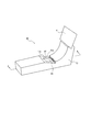
- FIG. 2 is an external perspective view showing the touch operation device 40 of FIG.
- FIG. 3 is a cross-sectional view taken along the line AA in which a part of the touch operation device 40 of FIG. 2 is enlarged.
- the configuration of the touch operation device 40 will be described in detail using FIGS. 1 to 3.
- the touch operation device 40 receives a touch operation input by the operator performed on the touch operation unit 42.
- the operator can perform a selection operation, an input operation, and the like on the touch operation unit 42 while visually recognizing the separated display unit 41.
- the operator is, for example, a driver driving a vehicle or a passenger sitting in a front passenger seat.
- the display unit 41 has at least one screen.
- the display unit 41 may be configured of any display device such as a liquid crystal display.
- the display part 41 is arrange
- the display device constituting the display unit 41 may be a touch panel display or a display incapable of touch operation.
- the display unit 41 will be described as a display incapable of touch operation.
- the touch operation device 40 may have a so-called head-up display type device in addition to or instead of the display unit 41.
- the head-up display type device has a light emitting unit that generates display information as display light, reflects the generated display light to be directed to an observer such as a driver, etc., and generates a virtual image over the front windshield.
- Display The observer is not limited to the driver but may be a passenger sitting in the front passenger seat.
- the touch operation unit 42 is disposed, for example, on the center console 50. As shown in FIG. 2, the touch operation unit 42 is disposed separately from the display unit 41.
- the touch operation unit 42 has a touch pad 42 a as shown in FIGS. 2 and 3. For example, the operator places his or her arm and wrist on the arm rest and palm rest, respectively, to bring the operator, in particular, a finger into contact with the touch pad 42a.
- the touch operation unit 42 detects a touch by the operator's operator.
- the touch pad 42a detects a touch by a touch object such as an operator's finger or a stylus pen at a corresponding touch position.
- the operator operates the information displayed on each screen constituting the display unit 41 by performing the touch operation on the touch operation unit 42, particularly the touch pad 42a.
- the touch pad 42a is formed of, for example, transparent glass, and a touch sensor formed of an arbitrary method such as a resistive film method, an electrostatic capacitance method, a surface acoustic wave method, an infrared method, or an electromagnetic induction method can be used. .
- the touch pad 42a will be described as being an electrostatic touch pad according to a capacitance method.
- the blower unit 43 is installed on the center console 50 so as to be adjacent to the touch operation unit 42.
- the blower unit 43 includes a blower duct 43a, a vent 43b provided at an outlet of the blower duct 43a, and a humidifier 43c disposed in the vicinity of the vent 43b.
- the blower 43 emits warm air or cold air to the operation surface of the touch operation unit 42, that is, the operation surface of the touch pad 42a. In other words, the wind passes through the air duct 43a and the vent 43b, and is discharged from the outlet to the operation surface of the touch operation unit 42.
- the air blower 43 may use an air conditioner mounted in the car as a wind source, or may use a dedicated simple fan.
- the blower 43 controls the amount of air released from the outlet by controlling the amount of opening and closing of the vent 43 b by the controller 45. More specifically, when it is desired to increase the amount of air released, the vent 43 b of the blower 43 is adjusted in the opening direction. When it is desired to reduce the amount of air released, the vent 43 b of the blower 43 is adjusted in the closing direction.
- the blower 43 can also release the wind containing water vapor by the on / off control of the humidifier 43 c by the controller 45.
- the load detection unit 44 is disposed immediately below the touch operation unit 42.
- the load detection unit 44 detects a vertical load on the touch pad 42 a that occurs when the operator performs a swipe operation on the touch operation unit 42. At this time, the operator's finger used for the swipe operation receives vertical force from the touch pad 42a as a reaction of the vertical load acting on the touch pad 42a.
- the load detection unit 44 outputs information on the detected vertical load to the control unit 45.
- the control unit 45 is a processor that controls and manages the entire touch operation device 40, including each functional block of the touch operation device 40.
- the control unit 45 is configured by a processor such as a central processing unit (CPU) that executes a program that defines a control procedure.
- a program is stored, for example, in an arbitrary storage device.
- the control performed by the awakening guidance system 1 for guiding the driver to the awake state will be mainly described. Specifically, when the awakening degree detection device 10 detects a decrease in the awakening degree of the driver, details of the awakening state guidance of the driver performed by the system control device 20 by controlling the automatic driving device 30 and the touch operation device 40 Explain to.
- the system control device 20 controls the automatic driving device 30 to drive a command to move the driver's operation hand to the touch operation unit 42.
- the automatic driving apparatus 30 causes the display unit 41 to display the command via the control unit 45, and urges the driver who recognizes the command to move the operation hand of the driver to the touch operation unit 42.
- the command by the automatic driving device 30 may relate to, for example, a selection action performed by the driver regarding automatic driving. More specifically, the automatic driving device 30 allows the driver to select whether or not to continue the automatic driving. For example, while the automatic driving device 30 displays the message “Do you want to continue the automatic driving?” On the display unit 41, the touch operation input on the selection of “Yes” or “No” is displayed on the touch operation unit 42. Prompt the driver to do it in
- the automatic driving device 30 acquires detection information from the awakening degree detection device 10 and requests the driver whether or not to continue the automatic driving. The number of selections may be increased.
- the command from the automatic driving device 30 may relate to, for example, the operation of the on-vehicle audio-visual device performed by the driver in the touch operation unit 42. More specifically, the autonomous driving device 30 may prompt the driver to operate the on-vehicle audio-visual device. For example, the automatic driving apparatus 30 switches the on-vehicle audio apparatus in the off state to the on state, raises the volume of the on-vehicle audio apparatus, switches the on-vehicle monitor apparatus in the off state to the on state, and In a state where control such as raising the brightness is performed, the driver is urged to restore the state of the on-vehicle audio-visual apparatus through the touch operation input on the touch operation unit 42.
- the autonomous driving device 30 may provide the driver with one of the two commands listed above as a specific example, or may provide the driver with two commands simultaneously.
- the automatic driving apparatus 30 may provide the driver with a command other than the above specific example, or may provide the driver with an arbitrary command to move the driver's operation hand to the touch operation unit 42. Good.
- the system control device 20 detects the touch of the driver's operation hand by the touch operation unit 42, the temperature of the operation hand is detected in the touch operation unit 42. Reduce. As a result, the driver's operator in the awakening state is rapidly cooled, and the driver is induced to the awake state.
- the system control device 20 may previously cool the touch operation unit 42 or the ambient atmosphere in contact with the driver's operator. The system control device 20 may cool the touch operation unit 42 or the ambient atmosphere when the touch operation unit 42 detects a touch of the operation hand of the driver.
- the system control device 20 may control the blower 43 via the controller 45 and may lower the temperature of the driver's operation hand by the cold air released by the blower 43.
- Cold air is wind of a temperature less than the ambient air temperature.
- the system control apparatus 20 may control the blower 43 via the control unit 45 so as to constantly emit cold air toward the touch operation unit 42.
- the system control device 20 controls the blower unit 43 via the control unit 45 so as to emit cold air toward the touch operation unit 42 when the awakening degree detection device 10 detects a decrease in the awakening degree of the driver. You may For example, when the touch operation unit 42 detects a touch of the driver's operation hand, the system control device 20 controls the blower unit 43 via the control unit 45 so as to emit cold air toward the touch operation unit 42. You may
- the system control device 20 detects the touch of the driver's operation hand by the touch operation unit 42, and the touch operation portion At 42, the temperature of the operating hand may be changed. For example, the system control device 20 lowers the temperature of the driver's operation hand in the touch operation unit 42 as described above. As a result, even if the driver is already awake, the driver's sympathetic nerve becomes dominant, and a further driver's awakening effect can be expected.
- the system control device 20 controls the blower 43 in the same manner as described above via the controller 45, and even if the temperature of the driver's operation hand is lowered by the cold air released by the blower 43. Good.
- the control of the blower 43 by the system control device 20 when the awakening degree detection device 10 does not detect a decrease in the awakening degree of the driver is not limited to this.
- the system control apparatus 20 causes the touch operation unit 42 to increase the temperature of the driver's operation hand.
- the system control device 20 may control the blower 43 via the controller 45, and may increase the temperature of the driver's operation hand by the warm air released by the blower 43.
- a warm air is a wind whose temperature exceeds the ambient air temperature.
- the system control device 20 switches the cool air or the warm air every number of times the touch operation unit 42 detects a touch of the driver's operation hand.
- the blower 43 may be controlled.
- the system control device 20 may control the blower 43 so as to alternately switch the cool air or the warm air each time the contact is detected.
- the system control device 20 may control the blower 43 to switch cold air or warm air at random each time the contact is detected.
- the automatic driving device 30 has been described as providing the above-described command to the driver when the awakening degree detection device 10 detects a decrease in the awakening degree of the driver, the present invention is not limited thereto.
- the same command is issued at predetermined time intervals. It may be provided to the driver.
- the predetermined time may be, for example, a time determined by a law, or a time appropriately determined by a vehicle maker, a driver, or the like.
- the system control device 20 When the awakening degree detection device 10 does not detect a decrease in the awakening degree of the driver, the system control device 20 performs the cold wind or the warm air in the same manner as described above for each number of instructions to the driver provided after the predetermined time has elapsed.
- the blower 43 may be controlled to switch the
- FIG. 4 is a flow chart showing an example of the operation of the system control apparatus 20 of FIG.
- the system control device 20 determines whether or not the operation has shifted to the automatic operation (step S101). If it is determined that the system control device 20 has shifted to the automatic operation, the process proceeds to step S102. For example, the system control device 20 causes the display unit 41 to display an automatic driving transition screen, and requests the driver to perform a selection operation. When the system control device 20 receives a touch operation input by the driver to shift to automatic driving in the touch operation unit 42, the system control device 20 shifts to automatic driving using the automatic driving device 30. If it is determined that the system control device 20 has not shifted to the automatic operation, the process returns to step S101.
- the system control device 20 determines whether a decrease in the awakening degree of the driver is detected (step S102). The system control device 20 determines, based on the detection information acquired from the awakening degree detecting device 10, whether the awakening degree of the driver is lowered. If the system control device 20 determines that the driver's awakening degree decrease is detected, the process proceeds to step S103. If the system control device 20 determines that the driver's arousal level decrease is not detected, the process proceeds to step S106.
- the system control device 20 provides the driver with a command to move the driver's operation hand to the touch operation unit 42 via the automatic driving device 30 when it is determined that the driver's arousal level decrease is detected. (Step S103). For example, based on the touch operation input on the touch operation unit 42, the automatic driving device 30 causes the driver to select whether to continue the automatic driving. For example, based on the touch operation input on the touch operation unit 42, the automatic driving device 30 causes the driver to operate the on-vehicle audio-visual device.
- the system control device 20 determines whether the touch of the driver's operation hand has been detected by the touch operation unit 42 based on the above-mentioned command (step S104). If the system control device 20 determines that the driver's touch of the operating hand has been detected, the process proceeds to step S105. If it is determined that the driver's touch of the operating hand is not detected, the system control device 20 returns to step S103 and provides the same command again.
- the system control device 20 controls the blower 43 via the control unit 45 to emit cold air (step S105). Thereafter, the system control device 20 proceeds to step S110.
- step S106 determines whether a predetermined time has elapsed. If the system control device 20 determines that the predetermined time has elapsed, it proceeds to step S107. If the system control device 20 determines that the predetermined time has not elapsed, it returns to step S102 and repeats the same flow.
- step S107 the system control device 20 provides a command to the driver via the automatic driving device 30, as in step S103 (step S107).
- the system control device 20 determines whether the touch of the driver's operation hand has been detected by the touch operation unit 42 based on the command provided in step S107 (step S108). If the system control device 20 determines that the driver's touch of the operating hand has been detected, the process proceeds to step S109. If it is determined that the driver's touch of the operating hand is not detected, the system control device 20 returns to step S107 and provides the same command again.
- the system control device 20 controls the blower 43 via the controller 45 to release cold air or warm air (step S109).
- the system control device 20 determines whether the driver has executed the command provided in step S103 or step S107 (step S110). If the system control device 20 determines that the driver has executed the command, the process proceeds to step S111. If the system control device 20 determines that the driver is not executing the command, the process returns to step S110.
- the system control device 20 controls the blower 43 via the controller 45 to stop the blower (step S111). Thereafter, the system control device 20 returns to step S102 and repeats the same flow.
- FIG. 5 is a flow chart showing an example of the operation of the system control apparatus 20 in step S109 of FIG. More specifically, FIG. 5 is a flowchart showing an example in which the system control device 20 controls the blower 43 alternately to switch the cold air or the warm air every number of instructions to the driver provided after a predetermined time has elapsed. It is. An example of control of the ventilation part 43 by the system control apparatus 20 performed in step S109 of FIG. 4 will be more specifically described using FIG. 5.
- the system control device 20 controls the blower 43 based on the command of step S107 of FIG. 4 executed in the previous flow and determines whether or not the cold air is released (step S201). If the system control device 20 determines that the cold air has been released, the process proceeds to step S202. If the system control device 20 determines that the cold air has not been released, that is, if it is determined that the warm air has been released, the process proceeds to step S203.
- the system control device 20 controls the blower 43 to release the warm air (step S202).
- the system control device 20 controls the blower 43 to release the cold air (step S203).
- the awakening guidance system 1 as described above can appropriately guide the awakening state of the driver even in a vehicle for autonomous driving. In other words, the awakening guidance system 1 can appropriately improve the awakening degree of the driver.
- the awakening guidance system 1 can appropriately induce the awakening degree of the driver by lowering the temperature of the operation hand in the touch operation unit 42, even if it is an automatically driven vehicle which does not need to grip the steering wheel.
- the awakening guidance system 1 can determine the position to cool the driver's operation hand at one place by urging the driver's operation hand to move to the touch operation unit 42. In other words, the awakening guidance system 1 does not need a device for detecting the position of the driver's operation hand to be cooled. Therefore, the awakening guidance system 1 can simplify its configuration.
- the awakening guidance system 1 can reliably cool the driver's operation hand by cooling the touch operation unit 42 or the ambient atmosphere in advance. In this way, the awakening guidance system 1 can reliably guide the driver to the awake state and promote appropriate monitoring of automatic driving by the driver.
- the awakening guidance system 1 can contribute to energy saving by cooling the touch operation unit 42 or the atmosphere around the touch operation unit 42 when the touch operation unit 42 detects the touch of the operation hand of the driver.
- the awakening guidance system 1 can suppress unnecessary energy consumption by cooling the touch operation unit 42 or the ambient atmosphere only when necessary.
- the awakening guidance system 1 can easily cool the driver's operation hand by using the cold air released by the blower 43.
- the awakening guidance system 1 is a new cooling mechanism for improving the driver's awakening degree by also using the air blowing unit 43 provided in the touch operation device 40 for improving the operability of the touch pad 42a described above. Do not need Thereby, the awakening guidance system 1 can simplify the configuration.
- the awakening guidance system 1 can use a part of the functions inherent to the automatic driving device 30 to improve the driver's arousal level by providing a command related to the selection action performed by the driver regarding automatic driving.
- the automatic driving device 30 needs to determine whether or not the driver appropriately monitors the automatic driving after each predetermined time, regardless of the presence or absence of the driver's awakening degree decrease. For this purpose, the automatic driving device 30 provides the driver with a command that requires some action to be taken.
- the awakening guidance system 1 does not require a new mechanism for improving the awakening degree of the driver by sharing the function of the automatic driving device 30 as described above. Thereby, the awakening guidance system 1 can simplify the configuration.
- the awakening guidance system 1 can always guide the driver to the awakening state by increasing the number of selections by the automatic driving device 30.
- the driver tends to always arrange his / her operation hand on the touch operation unit 42. Therefore, while the driver's operating hand is in contact with the touch operation unit 42, it is possible to continuously cool the operating hand, and the awakening guidance system 1 can maintain the awakening state of the driver for a long time.
- the awakening guidance system 1 can prompt the driver's response by the change of the sound or the video by providing the command related to the operation of the on-vehicle audio-visual apparatus performed by the driver in the touch operation unit 42.
- the awakening guidance system 1 can promote predetermined behavior with the driver given more force by acting directly on the driver's hearing or vision.
- each means and functions included in each step can be rearranged so as not to be logically contradictory, and it is possible to combine or divide a plurality of means or steps into one. is there.
- the awakening guidance system 1 is described above as changing the temperature of the driver's operation hand using the cold air or the warm air from the blower unit 43 of the touch operation device 40, the present invention is not limited thereto.
- the awakening induction system 1 may dispose an optional temperature control element such as a Peltier element immediately below the touch pad 42 a in addition to or instead of the blower 43.
- the awakening induction system 1 may change the temperature of the driver's operation hand by cooling or heating by an optional temperature control element such as a Peltier element, in addition to or instead of cooling or heating by the blower 43. .
Landscapes
- Engineering & Computer Science (AREA)
- Mechanical Engineering (AREA)
- Physics & Mathematics (AREA)
- Automation & Control Theory (AREA)
- Transportation (AREA)
- Human Computer Interaction (AREA)
- Thermal Sciences (AREA)
- Health & Medical Sciences (AREA)
- General Physics & Mathematics (AREA)
- Theoretical Computer Science (AREA)
- General Engineering & Computer Science (AREA)
- Mathematical Physics (AREA)
- Anesthesiology (AREA)
- Public Health (AREA)
- Heart & Thoracic Surgery (AREA)
- Hematology (AREA)
- Life Sciences & Earth Sciences (AREA)
- Animal Behavior & Ethology (AREA)
- General Health & Medical Sciences (AREA)
- Biomedical Technology (AREA)
- Veterinary Medicine (AREA)
- Psychology (AREA)
- Acoustics & Sound (AREA)
- User Interface Of Digital Computer (AREA)
- Traffic Control Systems (AREA)
- Air-Conditioning For Vehicles (AREA)
- Control Of Driving Devices And Active Controlling Of Vehicle (AREA)
Priority Applications (1)
| Application Number | Priority Date | Filing Date | Title |
|---|---|---|---|
| US16/650,364 US11124194B2 (en) | 2017-09-27 | 2018-06-19 | Wakefulness inducing system |
Applications Claiming Priority (2)
| Application Number | Priority Date | Filing Date | Title |
|---|---|---|---|
| JP2017-186838 | 2017-09-27 | ||
| JP2017186838A JP6898820B2 (ja) | 2017-09-27 | 2017-09-27 | 覚醒誘導システム |
Publications (1)
| Publication Number | Publication Date |
|---|---|
| WO2019064736A1 true WO2019064736A1 (ja) | 2019-04-04 |
Family
ID=65902773
Family Applications (1)
| Application Number | Title | Priority Date | Filing Date |
|---|---|---|---|
| PCT/JP2018/023348 Ceased WO2019064736A1 (ja) | 2017-09-27 | 2018-06-19 | 覚醒誘導システム |
Country Status (3)
| Country | Link |
|---|---|
| US (1) | US11124194B2 (https=) |
| JP (1) | JP6898820B2 (https=) |
| WO (1) | WO2019064736A1 (https=) |
Cited By (1)
| Publication number | Priority date | Publication date | Assignee | Title |
|---|---|---|---|---|
| US20240149634A1 (en) * | 2022-11-09 | 2024-05-09 | Jvis-Usa, Llc | Vehicular Temperature Regulating System and Panel Assembly Including a Touch Panel Configured to be Heated or Cooled within a Passenger Compartment of a Vehicle |
Families Citing this family (7)
| Publication number | Priority date | Publication date | Assignee | Title |
|---|---|---|---|---|
| KR102679466B1 (ko) * | 2018-12-11 | 2024-07-01 | 현대자동차주식회사 | 차량 및 그 제어방법 |
| KR20210008237A (ko) * | 2019-07-11 | 2021-01-21 | 현대자동차주식회사 | 차량용 공조 제어시스템 및 제어방법 |
| US11912307B2 (en) * | 2020-03-18 | 2024-02-27 | Waymo Llc | Monitoring head movements of drivers tasked with monitoring a vehicle operating in an autonomous driving mode |
| KR102378665B1 (ko) * | 2020-08-26 | 2022-03-25 | 주식회사 켐트로닉스 | 차량의 긴급 제어 시스템 및 방법 |
| JP2024005699A (ja) * | 2022-06-30 | 2024-01-17 | パナソニックIpマネジメント株式会社 | 車両およびアームレスト |
| JP7659235B2 (ja) | 2022-11-18 | 2025-04-09 | トヨタ自動車株式会社 | 車両運転支援装置、車両運転支援方法及び車両運転支援プログラム |
| CN115804590B (zh) * | 2022-11-25 | 2025-03-04 | 深圳先进技术研究院 | 觉醒状态检测系统及方法 |
Citations (6)
| Publication number | Priority date | Publication date | Assignee | Title |
|---|---|---|---|---|
| JP2011118831A (ja) * | 2009-12-07 | 2011-06-16 | Denso Corp | 覚醒支援装置 |
| JP2011159108A (ja) * | 2010-02-01 | 2011-08-18 | Denso Corp | 覚醒支援装置 |
| JP2013015993A (ja) * | 2011-07-04 | 2013-01-24 | Nissan Motor Co Ltd | 運転支援装置および運転支援方法 |
| JP2016115356A (ja) * | 2014-12-12 | 2016-06-23 | ソニー株式会社 | 自動運転制御装置および自動運転制御方法、並びにプログラム |
| JP2017027180A (ja) * | 2015-07-17 | 2017-02-02 | 日産自動車株式会社 | 車両制御装置及び車両制御方法 |
| JP2017030518A (ja) * | 2015-07-31 | 2017-02-09 | 株式会社デンソー | 運転支援制御装置 |
Family Cites Families (4)
| Publication number | Priority date | Publication date | Assignee | Title |
|---|---|---|---|---|
| JP5729188B2 (ja) * | 2011-07-19 | 2015-06-03 | 日産自動車株式会社 | 運転支援装置および運転支援方法 |
| JP5842857B2 (ja) * | 2013-04-08 | 2016-01-13 | 株式会社デンソー | 覚醒度改善装置 |
| JP6914832B2 (ja) * | 2014-10-31 | 2021-08-04 | ジェンサーム インコーポレイテッドGentherm Incorporated | 車両ミクロ気候システムと制御方法 |
| US9725036B1 (en) * | 2016-06-28 | 2017-08-08 | Toyota Motor Engineering & Manufacturing North America, Inc. | Wake-up alerts for sleeping vehicle occupants |
-
2017
- 2017-09-27 JP JP2017186838A patent/JP6898820B2/ja active Active
-
2018
- 2018-06-19 US US16/650,364 patent/US11124194B2/en active Active
- 2018-06-19 WO PCT/JP2018/023348 patent/WO2019064736A1/ja not_active Ceased
Patent Citations (6)
| Publication number | Priority date | Publication date | Assignee | Title |
|---|---|---|---|---|
| JP2011118831A (ja) * | 2009-12-07 | 2011-06-16 | Denso Corp | 覚醒支援装置 |
| JP2011159108A (ja) * | 2010-02-01 | 2011-08-18 | Denso Corp | 覚醒支援装置 |
| JP2013015993A (ja) * | 2011-07-04 | 2013-01-24 | Nissan Motor Co Ltd | 運転支援装置および運転支援方法 |
| JP2016115356A (ja) * | 2014-12-12 | 2016-06-23 | ソニー株式会社 | 自動運転制御装置および自動運転制御方法、並びにプログラム |
| JP2017027180A (ja) * | 2015-07-17 | 2017-02-02 | 日産自動車株式会社 | 車両制御装置及び車両制御方法 |
| JP2017030518A (ja) * | 2015-07-31 | 2017-02-09 | 株式会社デンソー | 運転支援制御装置 |
Cited By (1)
| Publication number | Priority date | Publication date | Assignee | Title |
|---|---|---|---|---|
| US20240149634A1 (en) * | 2022-11-09 | 2024-05-09 | Jvis-Usa, Llc | Vehicular Temperature Regulating System and Panel Assembly Including a Touch Panel Configured to be Heated or Cooled within a Passenger Compartment of a Vehicle |
Also Published As
| Publication number | Publication date |
|---|---|
| JP2019061562A (ja) | 2019-04-18 |
| US20200231165A1 (en) | 2020-07-23 |
| US11124194B2 (en) | 2021-09-21 |
| JP6898820B2 (ja) | 2021-07-07 |
Similar Documents
| Publication | Publication Date | Title |
|---|---|---|
| JP6898820B2 (ja) | 覚醒誘導システム | |
| US10710594B2 (en) | Occupant-status prediction system | |
| CN108430818B (zh) | 用于操作机动车辆的方法,驾驶员辅助系统和机动车辆 | |
| US9483927B2 (en) | Method and system for controlling a vehicle during an autonomous control mode | |
| CN105556424B (zh) | 运行机动车多个显示装置的方法和系统及有该系统的机动车 | |
| US20160196098A1 (en) | Method and system for controlling a human-machine interface having at least two displays | |
| JP6776681B2 (ja) | ドライバ状態判定装置、及びドライバ状態判定プログラム | |
| CN106457956A (zh) | 具有感觉反馈的控制装置 | |
| US20200137665A1 (en) | Systems, devices, and methods for controlling operation of wearable displays during vehicle operation | |
| JP2005329800A (ja) | 車載機器制御装置 | |
| JP6668999B2 (ja) | 運転支援装置 | |
| US20240326825A1 (en) | Autonomous vehicle feedback system and method of operating an autonomous vehicle | |
| CN117864046A (zh) | 检测车辆操作者汽车压力和/或焦虑并通过车厢环境实施补救措施的系统和方法 | |
| WO2018030018A1 (ja) | 運転支援装置 | |
| JP6593247B2 (ja) | 安全運転支援装置 | |
| JP2012179959A (ja) | 表示制御システム、表示制御装置及びプログラム | |
| JP6702166B2 (ja) | 車両用インターフェイス | |
| JP6673070B2 (ja) | ドライバ状態誘導装置、及びドライバ状態誘導プログラム | |
| US11565635B2 (en) | Vehicle control device | |
| JP2019130992A (ja) | 機器操作装置 | |
| KR101619267B1 (ko) | 차량의 hud 제어 방법, 및 차량의 hud 제어 장치 | |
| JP2018185765A (ja) | ジェスチャ入力システム | |
| JP7803227B2 (ja) | 運転支援装置 | |
| US20250114557A1 (en) | Temperature-related drowsiness mitigation strategy | |
| WO2022168696A1 (ja) | ジェスチャ操作結果を表示する表示システム |
Legal Events
| Date | Code | Title | Description |
|---|---|---|---|
| 121 | Ep: the epo has been informed by wipo that ep was designated in this application |
Ref document number: 18863402 Country of ref document: EP Kind code of ref document: A1 |
|
| DPE1 | Request for preliminary examination filed after expiration of 19th month from priority date (pct application filed from 20040101) | ||
| NENP | Non-entry into the national phase |
Ref country code: DE |
|
| 122 | Ep: pct application non-entry in european phase |
Ref document number: 18863402 Country of ref document: EP Kind code of ref document: A1 |