WO2019061473A1 - Unmanned aerial vehicle frame assembly, and unmanned aerial vehicle - Google Patents
Unmanned aerial vehicle frame assembly, and unmanned aerial vehicle Download PDFInfo
- Publication number
- WO2019061473A1 WO2019061473A1 PCT/CN2017/104928 CN2017104928W WO2019061473A1 WO 2019061473 A1 WO2019061473 A1 WO 2019061473A1 CN 2017104928 W CN2017104928 W CN 2017104928W WO 2019061473 A1 WO2019061473 A1 WO 2019061473A1
- Authority
- WO
- WIPO (PCT)
- Prior art keywords
- arm
- link
- center
- convex portion
- elastic
- Prior art date
Links
Images


Classifications
-
- B—PERFORMING OPERATIONS; TRANSPORTING
- B64—AIRCRAFT; AVIATION; COSMONAUTICS
- B64U—UNMANNED AERIAL VEHICLES [UAV]; EQUIPMENT THEREFOR
- B64U30/00—Means for producing lift; Empennages; Arrangements thereof
- B64U30/20—Rotors; Rotor supports
- B64U30/29—Constructional aspects of rotors or rotor supports; Arrangements thereof
- B64U30/293—Foldable or collapsible rotors or rotor supports
-
- B—PERFORMING OPERATIONS; TRANSPORTING
- B64—AIRCRAFT; AVIATION; COSMONAUTICS
- B64U—UNMANNED AERIAL VEHICLES [UAV]; EQUIPMENT THEREFOR
- B64U10/00—Type of UAV
- B64U10/10—Rotorcrafts
- B64U10/13—Flying platforms
- B64U10/14—Flying platforms with four distinct rotor axes, e.g. quadcopters
Definitions
- Embodiments of the present invention relate to the field of drones, and more particularly to a rack assembly and a drone of a drone.
- Unmanned aerial vehicles are often used in aerial photography, remote air monitoring, monitoring, and detection.
- Unmanned aerial vehicles generally consist of a central frame, an arm, a power component, a tripod, and several parts of the equipment to be mounted.
- the equipment used for the work is generally arranged above or below the center frame, and the function of the stand is to support the entire aircraft to avoid contact with the ground when the aircraft or the working equipment is hung. Since the UAV of the fixed arm structure is large in size and inconvenient to carry, folding the arm is a more common method.
- the UAV of the folding arm of the prior art can only lock a single arm once, and cannot lock the two arms at a time, resulting in low operational efficiency. .
- the embodiment of the invention provides a rack assembly and a drone of a drone to solve the problem that the two arms cannot be locked at one time in the prior art, resulting in low operation efficiency.
- a first aspect of the present invention provides a rack assembly for a drone, including: a center frame, a first arm and a second arm rotatably coupled to the center frame, and a locking mechanism that is synchronously locked by the arm and the second arm, the locking mechanism comprising: a synchronization device, a locking device and a mounting seat;
- the first arm and the second arm are rotatable relative to the mounting seat, and the mounting seat is stationary relative to the center frame;
- the synchronizing device is disposed between the first arm and the second arm, the synchronizing device includes a plurality of relatively rotatable transmission members, and the plurality of transmission members rotate to make the first arm and the second arm The arm rotates synchronously;
- the locking device is configured to lock at least one of the plurality of transmission members, at least one of the transmission devices is provided with a convex portion, and the locking device comprises a mounting portion disposed on the mounting seat for the a resilient abutting assembly with a convex portion;
- the elastic abutting assembly abuts a convex portion on at least one of the synchronizing devices to block rotation of the transmission member having the convex portion; the transmission member having the convex portion overcomes the elasticity when an external force acts The transmission member having the convex portion can continue to rotate by the elastic resistance applied by the abutting member.
- the rack assembly of the UAV provided by the embodiment of the invention is provided with a synchronization device, a locking device and a mounting seat, and the first arm and the second arm rotate relative to the mounting seat, and the mounting seat does not move relative to the center frame, and is synchronized.
- the device rotates the first arm and the second arm synchronously through a plurality of relatively rotatable transmission members thereof, at least one of the transmission devices is provided with a convex portion, and the locking device comprises a resilient abutting assembly matched with the convex portion
- the convex portion is rotated until the elastic abutting assembly is abutted by the elastic abutting assembly, the transmission member cannot rotate under the elastic resistance of the elastic abutting assembly, and the entire synchronizing device cannot rotate, the first arm and the first arm
- the two arms are locked, and when the external force overcomes the elastic resistance exerted by the elastic abutting assembly, the transmission member having the convex portion can continue to rotate, so that the entire synchronizing device can continue to rotate, and the first arm and the second arm can rotate. . This achieves locking of the two arms at a time, improving operational efficiency.
- a second aspect of the present invention provides a rack assembly for a drone, including: a center frame, a first arm and a second arm rotatably coupled to the center frame, and a locking mechanism that is synchronously locked by the arm and the second arm, the locking mechanism comprising: a synchronization device, a locking device and a mounting seat;
- the first arm and the second arm are rotatable relative to the mounting seat, and the mounting seat is stationary relative to the center frame;
- the synchronization device includes a center link, a first arm link set, and a second arm link set, the center link is rotatably coupled to the mount; one end of the center link The first end of the first arm link set is hinged, the end of the first arm link set is hinged with the first arm; the other end of the center link and the second arm link The head end of the group is hinged, the end of the second arm link set is hinged with the second arm; the center link, the first arm link set, and the second arm link set are used for transmitting Powering to drive the first arm and the second arm to rotate synchronously;
- the locking device is disposed between the mounting seat and the center link, and the locking device includes a locked state and an unlocked state, wherein the locking device provides resistance to hinder the The center link rotates until the center link overcomes the resistance by an external force, the locking device switches to an unlocked state, and the center link is rotatable relative to the mount.
- the rack assembly of the UAV provided by the embodiment of the present invention is provided with a synchronization device, a locking device and a mounting seat, and the first arm and the second arm rotate relative to the mounting seat, and the mounting seat remains stationary relative to the center frame.
- the synchronizing device comprises a center link, a first arm link set and a second arm link set, the central link is rotatably connected to the mount, the first arm, the first arm link set, the center link
- the rod, the second arm link set and the second arm are sequentially hinged to form a link transmission, and the locking device is disposed between the mounting seat and the center link, and hinders the rotation of the center link by providing resistance, the first arm And the second arm is in a locked state until the center link continues to rotate against the resistance, and the first arm and the second arm are in an unlocked state. Further, it is thereby achieved that the two arms are locked at a time, which improves the operation efficiency.
- a third aspect of the present invention provides a drone, comprising: a rack assembly and a power device disposed on the rack assembly, wherein the power device is configured to provide flight power to the drone;
- the rack assembly includes: a center frame, a first arm and a second arm rotatably coupled to the center frame, and a locking mechanism for synchronously locking the first arm and the second arm
- the locking mechanism includes: a synchronization device, a locking device, and a mount;
- the first arm and the second arm are rotatable relative to the mounting seat, and the mounting seat is stationary relative to the center frame;
- the synchronizing device is disposed between the first arm and the second arm, the synchronizing device includes a plurality of relatively rotatable transmission members, and the plurality of transmission members rotate to make the first arm and the second arm The arm rotates synchronously;
- the locking device is configured to lock at least one of the plurality of transmission members, at least one of the transmission devices is provided with a convex portion, and the locking device comprises a mounting portion disposed on the mounting seat for the a resilient abutting assembly with a convex portion;
- the elastic abutting assembly abuts a convex portion on at least one of the synchronizing devices to block rotation of the transmission member having the convex portion; the transmission member having the convex portion overcomes the elasticity when an external force acts The transmission member having the convex portion can continue to rotate by the elastic resistance applied by the abutting member.
- the unmanned aerial vehicle provided by the embodiment of the invention provides a synchronization device, a locking device and a mounting seat, and the first arm and the second arm rotate relative to the mounting seat, and the synchronizing device makes the first through the plurality of relatively rotatable transmission members thereof
- One arm and the second arm rotate synchronously, at least one transmission member in the synchronizing device
- the protrusion is provided with a convex portion
- the locking device comprises a resilient abutting assembly matched with the convex portion, and when the convex portion is rotated until the elastic abutting assembly is abutted by the elastic abutting assembly, under the elastic resistance of the elastic abutting assembly,
- the transmission member cannot be rotated, so that the entire synchronizing device cannot be rotated, and the first arm and the second arm are locked, and when the external force overcomes the elastic resistance exerted by the elastic abutting assembly, the transmission member having the convex portion can continue to rotate, and further The entire synchronizing device can continue
- the unmanned aerial vehicle provided by the fourth aspect of the present invention includes: a rack assembly and a power device disposed on the rack assembly, wherein the power device is configured to provide flight power to the drone;
- the frame assembly includes: a center frame, a first arm and a second arm rotatably connected to the center frame, and a locking mechanism for synchronously locking the first arm and the second arm
- the locking mechanism comprises: a synchronization device, a locking device and a mount;
- the first arm and the second arm rotate relative to the mounting seat, and the mounting seat remains stationary relative to the center frame;
- the synchronization device includes a center link, a first arm link set, and a second arm link set, the center link is rotatably coupled to the mount; one end of the center link The first end of the first arm link set is hinged, the end of the first arm link set is hinged with the first arm; the other end of the center link and the second arm link The head end of the group is hinged, the end of the second arm link set is hinged with the second arm; the center link, the first arm link set, and the second arm link set are used for transmitting Powering to drive the first arm and the second arm to rotate synchronously;
- the locking device is disposed between the mounting seat and the center link, and the locking device includes a locked state and an unlocked state, wherein the locking device provides resistance to block the center link Rotating until the center link overcomes the resistance under the action of an external force, the locking device is switched to the unlocked state, and the center link is rotatable relative to the mount.
- the unmanned aerial vehicle provided by the embodiment of the invention is provided with a synchronization device, a locking device and a mounting seat, and the first arm and the second arm rotate relative to the mounting seat, and the synchronizing device comprises a central connecting rod and a first arm connecting rod set And a second arm link set, the center link is rotatably coupled to the mount, the first arm, the first arm link set, the center link, the second arm link set, and the second arm
- the locking device is disposed between the mounting seat and the center link, and the first arm and the second arm are locked until the center link is overcome by providing resistance to block the rotation of the center link. The resistance continues to rotate and the first arm and the second arm are unlocked. Furthermore, this is achieved Locking both arms at a time increases operational efficiency.
- FIG. 1 is a schematic structural diagram of a rack assembly of a drone according to an embodiment of the present invention
- FIG. 2 is a schematic structural diagram of a connection structure of a rack assembly of a drone according to an embodiment of the present invention
- FIG. 3 is an exploded view of a rack assembly of a drone according to an embodiment of the present invention.
- FIG. 4 is a schematic diagram of locking of a rack assembly of a drone according to an embodiment of the present invention.
- FIG. 5 is another schematic diagram of locking of a rack assembly of a drone according to an embodiment of the present invention.
- FIG. 6 is a schematic structural diagram of a drone according to an embodiment of the present invention.
- a component when referred to as being "fixed” to another component, it can be directly on the other component or the component can be in the middle. When a component is considered to "connect” another component, it can be directly connected to another component or possibly a central component.
- FIG. 1 is a schematic structural diagram of a rack assembly of a drone according to an embodiment of the present invention
- FIG. 2 is a schematic diagram of a connection structure of a rack assembly of a drone according to an embodiment of the present invention
- FIG. 4 is a schematic diagram of a lock of the rack assembly of the drone provided by the embodiment of the present invention
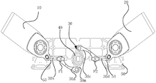
- the rack assembly of the drone provided by the embodiment includes: a center frame, a first arm 10 and a second arm 20 rotatably connected to the center frame, and A locking mechanism that synchronously locks the first arm 10 and the second arm 20 includes a synchronizing device 30, a locking device 40, and a mount 50.
- the first arm 10 and the second arm 20 can be fixed to the center frame by the arm rotation shafts, respectively.
- first arm 10 and the second arm 20 are rotatable relative to the mount 50, and the mount 50 remains stationary relative to the center frame.
- first arm 10 and the second arm 20 rotate relative to the mount 50, and the mount 50 remains stationary relative to the center frame.
- at least two implementation methods are included:
- the mounting seat 50 can be rotatably coupled to the first arm 10 and the second arm 20 via a rotating shaft. More specifically, the rotating shaft of the mounting base 50 can be the same as the rotating shaft of the first arm 10 and the second arm 20 and the center frame. The shaft, as such, when the first arm 10 and the second arm 20 are rotated relative to the center frame, the mount 50 may not rotate.
- the mount 50 may include an upper casing (not shown) disposed oppositely, the lower casing 51, the first arm 10, and the second arm 20 may be located in the upper casing and the lower casing 51. between.
- One end of the upper casing and one end of the lower casing 51, and the first arm 10 and the center frame are rotatably coupled by the first arm rotating shaft a.
- the other end of the upper casing and the other end of the lower casing 51, and the second arm 20, the center frame may be rotatably coupled by the second arm rotating shaft b.
- the mount 50 can be directly fixed to the center frame, for example, welded to the center frame, or fixedly connected to the center frame by a connecting member, or integrally formed with the center frame, and the first arm 10 and the second arm 20 are opposite to each other. When the center frame is rotated, the mount 50 may not rotate.
- the synchronizing device 30 is disposed between the first arm 10 and the second arm 20.
- the synchronizing device 30 includes a plurality of relatively rotatable transmission members, and the plurality of transmission members rotate to make the first arm 10 and the second arm 20 Rotate synchronously.
- the plurality of relatively rotatable transmission members may be a plurality of intermeshing teeth
- the wheel, the plurality of hinged connecting rods, or other transmission members that can transmit power to enable the first arm 10 and the second arm 20 to rotate synchronously, are not particularly limited in this embodiment, and may be selected according to actual conditions. .
- the locking device 40 is configured to lock at least one of the plurality of transmission members, and at least one of the transmission devices 30 is provided with a convex portion 31.
- the locking device 40 includes a protrusion portion 31 disposed on the mounting seat 50 for engaging the convex portion 31.
- the elastic abutment assembly 41 may include one or more.
- the elastic abutment assembly 41 can be fixed to the mounting seat 50 in a detachable or non-detachable manner, such as screwing, snapping, welding, riveting, and the like.
- the locking device 40 is used for locking at least one of the plurality of transmission members, that is, at least one of the plurality of transmission members can be locked by the locking device 40, and should not be understood as any of the plurality of transmission members. One can be locked for the locking device 40.
- the elastic abutment assembly 41 abuts the convex portion 31 on at least one of the transmission members 30 to block the rotation of the transmission member having the convex portion 31; the transmission member having the convex portion overcomes the elastic abutment under the action of an external force
- the elastic resistance exerted by the assembly 41 enables the transmission member having the convex portion 31 to continue to rotate.
- power transmission in the synchronizing device 30 can be continued, and the first arm 10 and the second arm 20 can be synchronously transmitted by the synchronizing device 30.
- the convex portion 31 is rotated to an angle, it can be abutted by the elastic abutting assembly 41.
- the first arm 10 and the second arm 20 can be at In the unfolded state, the first arm 10 and the second arm 20 are locked in the deployed state, and after the resistance of the elastic abutment assembly 41 is overcome, the first arm 10 and the second arm 20 can be freely rotated, for example, Free to rotate to the folded state.
- the first arm 10 and the second arm 20 can be relatively rotated to a minimum preset angle.
- the first arm 10 and the second arm 20 are rotated to be parallel to each other, that is, the angle is zero.
- the first arm 10 and the second arm 20 are relatively rotated to a minimum preset angle, the first arm 10 and the second arm 20 are in a folded state.
- the folded state here is that the first arm 10 and the second arm 20 are relatively folded, and it should not be understood that the first arm 10 and the second arm 20 are respectively in a folded state.
- the first arm 10 and the second arm 20 can be relatively rotated to a maximum preset angle, for example, the first arm 10 and the second arm 20 are rotated at an angle of 180 degrees.
- the first arm 10 and the second arm 20 are in an unfolded state.
- the unfolded state is that the first arm 10 and the second arm 20 are separated from each other in an unfolded state, and it should not be understood that the first arm 10 and the second arm 20 are respectively in an unfolded state.
- the angle between the first arm 10 and the second arm 20 can also be greater than zero, in the first arm.
- the angle between the first arm 10 and the second arm 20 may also be less than 180 degrees.
- it can be determined according to the number of the arm and the arrangement position, and the preset deployment form.
- the embodiment is not limited.
- the locking device 40 may include two, and the two locking devices 40 may be respectively disposed on both sides of the transmission member having the convex portion 31, whereby the locking effect can be further improved.
- the rack assembly of the UAV provided by the embodiment of the invention is provided with a synchronization device, a locking device and a mounting seat, and the first arm and the second arm rotate relative to the mounting seat, and the mounting seat does not move relative to the center frame, and is synchronized.
- the device rotates the first arm and the second arm synchronously through a plurality of relatively rotatable transmission members thereof, at least one of the transmission devices is provided with a convex portion, and the locking device comprises a resilient abutting assembly matched with the convex portion
- the convex portion is rotated until the elastic abutting assembly is abutted by the elastic abutting assembly, the transmission member cannot rotate under the elastic resistance of the elastic abutting assembly, and the entire synchronizing device cannot rotate, the first arm and the first arm
- the two arms are locked, and when the external force overcomes the elastic resistance exerted by the elastic abutting assembly, the transmission member having the convex portion can continue to rotate, so that the entire synchronizing device can continue to rotate, and the first arm and the second arm can rotate. . This achieves locking of the two arms at a time, improving operational efficiency.
- the elastic abutment assembly 41 may include a fitting recess 411 that cooperates with the convex portion 31.
- the locking device 40 maintains the transmission member having the convex portion 31 in the locked state.
- the shape of the fitting recess 411 may be completely matched with the convex portion 31, or may be slightly larger than the convex portion 31.
- the convex portion 31 can be restrained under the wall surface of the fitting concave portion 411, and more preferably The ground is maintained in a locked state to improve the stability of the lock.
- the transmission member continues to rotate under the action of a large external force, and the elastic resistance of the elastic abutting assembly 41 received by the transmission member having the convex portion 31 is smaller and smaller, and the transmission member having the convex portion 31 is rotatable.
- the one arm 10 and the second arm 20 can in turn also rotate.
- the elastic abutment assembly 41 is gradually released, and the transmission member having the convex portion 31 is gradually switched from the unlocked state to the locked state.
- the elastic abutting assembly 41 is gradually released, and the elastic abutting assembly 41 facilitates the convex portion 31 to enter the fitting recess 31, and the convex portion 31 is completely rotated.
- the elastic abutment assembly 41 is in a released state before entering the fitting recess 31 and before the convex portion 31 is turned out of the fitting recess 31, in the process, the convex portion 31 can smoothly rotate in the fitting recess 31, and therefore, in the process
- the transmission member having the convex portion 31 is in an unlocked state, and the first arm 10 and the second arm 20 can be smoothly rotated until the convex portion 31 is completely turned into the fitting recess 31 to reach the locked state.
- the locking effect can be further improved, and the stability after locking can be improved.
- the convex portion 31 in this embodiment can be convex outward in a direction parallel to the rotational axis of the transmission member in which it is located.
- the convex portion 31 on one of the transmission members may include a plurality of concave portions 32 formed on the end surface of the convex portion 41, and the plurality of convex portions 31 and the concave portions 32 are continuously arranged to form a wave-shaped end surface W1.
- Each adjacent convex portion 31 and the concave portion 32 have a curved surface transition.
- a wavy fitting surface W2 for engaging the wavy end surface is formed on the elastic abutment assembly 41. In the state shown in FIG. 4, the wavy end surface W1 is engaged with the undulating mating surface W2, so that during the counterclockwise rotation of the transmission member having the convex portion 31, the elastic abutment assembly 41 is gradually compressed to block the convex portion 31.
- the transmission member is rotated to maintain the first arm 10 and the second arm 20 at their current positions to some extent.
- the elastic abutting assembly 41 gradually recovers and deforms so that the contact surface of the wavy end surface W1 and the wavy fitting surface W2 is favorable for rotation.
- the transmission member having the convex portion 31 is rotated to the lowest position of the wavy fitting surface W2, it will repeatedly enter the stage of hindering the rotation, That is, it enters the locked state.
- the entire synchronizing device 30 can enter the locked state at a plurality of rotation angles, that is, the first arm 10 and the second arm 20 can be made to be different in plurality In the angled state, the state is locked.
- the elastic abutment assembly 41 may include a rigid urging member 41a for engaging with the convex portion 31, and an elastic member disposed between the rigid urging member 41a and the mount 50. 41b.
- the elastic member 41b may be an axial elastic member, specifically an axial expansion spring.
- the elastic member 41b may be fixedly connected to the mounting seat 50 at one end and fixedly connected to the rigid biasing member 41a at the other end.
- the elastic member 41b may be fixedly connected to the mounting seat 50 or the rigid urging member 41a at one end, and the other end of the elastic member 41b may abut against the rigid urging member 41a or the mounting seat 50.
- This embodiment provides elastic resistance by the elastic member 41b, and provides a contact surface with the transmission member having the convex portion 31 by the rigid biasing member 41a, which is simple in structure and stable in function.
- the elastic abutment assembly 41 can also be a series of components that can provide elastic resistance, such as a spring piece and a rubber.
- a guide shaft 52 may be fixed to the mounting seat 50, and the rigid urging member 41a and the elastic member 41b may be sleeved on the outer side of the guide shaft 52.
- the outer diameter of the guide shaft 52 may be slightly larger than the diameters of the rigid urging member 41a and the elastic member 41b, thereby not affecting the axial movement of the rigid urging member 41a along the guide shaft 52, and also the elastic member 41b. The limit is performed to prevent the elastic member 41b from swinging.
- the elastic abutment assembly 41 applies elastic resistance to the transmission member having the convex portion 31 in the synchronizing device 30 in a predetermined direction, and can stably maintain the transmission member having the convex portion 31 and the rigid urging member 41a. Good contact between.
- a stopper portion 521 for blocking the circumferential rotation of the rigid biasing member 41a may be formed on the guide shaft 52.
- the transmission member having the convex portion 31 may drive the rigid urging member 41a to rotate due to the interaction of the urging force and the reaction force, especially in
- the rigid urging member 41a is also rotated by the transmission member having the projection 31, the transmission of the transmission member having the projection 31 cannot be prevented.
- the rotation of the rigid urging member 41a is blocked by the blocking portion 521, so that the rigid urging member 41a can only move axially along the guide shaft 52, so that the locking effect of the locking device 40 is more reliable.
- the specific structure of the blocking portion 521 can be various, and several forms are listed below:
- the blocking portion 521 may be a sliding rail (not shown) extending on the outer side wall of the guiding shaft 52 and extending in the axial direction.
- the inner side wall of the rigid urging member 41a is provided with Slider mating chute (not shown).
- the blocking portion 521 is a sliding groove (not shown) extending in the axial direction on the outer side wall of the guiding shaft, correspondingly, on the inner side wall of the rigid urging member 41a.
- a slide rail (not shown) is provided for cooperating with the chute.
- the guide shaft 52 has a non-circular cross section, and the inner side wall shape of the rigid urging member 41a matches the cross-sectional shape of the guide shaft 52.
- the guide shaft 52 is cut in a direction parallel to the axial direction to form a longitudinal section such that the guide shaft 52 is non-circular, and the longitudinal section formed after being cut forms the blocking portion 521.
- the specific form of the blocking portion 521 is not limited to the above description, and a person skilled in the art can specifically design according to the actual situation, and details are not described herein.
- the embodiment further defines the synchronization device 30 on the basis of the first embodiment or the second embodiment, and the synchronization device 30 may include a link transmission component.
- the rotation shaft of at least one of the link transmission assemblies is fixed to the mount 50.
- the link transmission assembly may include a center link 30m, a first transition link 30a, a first arm link 30b, a second transition link 30c, and a second arm link 30d;
- a first linear slide 53 and a second linear slide 54 may be formed on the mount 50;
- the center link 30m may be rotatably coupled to the mount 50 via a rotating shaft.
- the first end of the first transition link 30a is hinged to one end of the center link 30m, and the end of the first transition link 30a is hinged to the first end of the first arm link 30b; the end of the first arm link 30b is An arm is hinged, and a hinge portion of the first transition link 30a and the first arm link 30b is slidably disposed in the first linear slide 53.
- the first end of the second transition link 30c is hinged to the other end of the center link 30m, the end of the second transition link 30c is hinged to the head end of the second arm link 30d, and the end of the second arm link 30d is
- the second arm 20 is hinged, and the hinge of the second transition link and the second arm link 30d is slidably disposed on the second straight line. In the road 54.
- the first arm 10 the first arm link 30b, the first transition link 30a, the center link 30m, the second transition link 30c, the second arm link 30d, and the second machine
- the arms 20 together form a seven-link structure.
- the hinge axis of the first arm link 30b and the first arm 10 and the first arm link 30b of the first arm link 30b rotate relative to the center frame.
- the second arm link 30d and the hinge axis of the second arm 20 and the second arm link 30d are different axes with respect to the second arm pivot b of the center frame.
- the center link 30m pushes the first transition link 30a to rotate, and the end of the first transition link 30a Sliding to the left in the first linear slide 53, driving the first arm link 30b to rotate counterclockwise, the first arm 10 rotates clockwise; meanwhile, the center link 30m pushes the second transition link 30c to rotate, second The end of the transition link 30c slides to the right in the second linear slide 54 to drive the second arm link 30d to rotate clockwise, and the second arm 20 rotates counterclockwise, that is, the first arm 10 and the second machine are realized.
- the arm 30 is simultaneously rotated in a direction in which the angle is relatively decreased to a folded state.
- the center link 30m When the first arm 10 and the second arm 30 are in the folded state, the center link 30m is rotated in the counterclockwise direction, and the center link 30m pushes the first transition link 30a to rotate, and the end of the first transition link 30a is
- the first linear slide 53 slides to the right to drive the first arm link 30b to rotate clockwise, the first arm 10 rotates counterclockwise; meanwhile, the center link 30m pushes the second transition link 30c to rotate, the second transition
- the end of the connecting rod 30c slides to the left in the second linear slide 54 to drive the second arm link 30d to rotate counterclockwise, and the second arm 20 rotates clockwise, that is, the first arm 10 and the second arm are realized. 30 simultaneously rotates in a direction in which the angle is relatively increased.
- first arm 10 or the second arm 20 when the first arm 10 or the second arm 20 is rotated, power can be transmitted from the first arm 10 to the second arm 20 or from the second arm 20 to the first through the above-described transmission.
- One arm 10 The specific delivery process will not be described here.
- the first linear slide 53 may include a linear groove and/or a linear through hole; and/or the second linear slide 54 includes a linear groove and/or a straight through hole.
- the center link 30m is formed with a convex portion 31.
- Locking device 40 locks the center
- the convex portion 31 on the link 30m blocks the center link 30m from rotating to block the power transmission of the synchronizing device 30, and locks the first arm 10 and the second arm 20.
- the link transmission component includes a center link 30m, and the first The arm link and the second arm link; the center link 30m is rotatably coupled to the mount 50 via the rotating shaft.
- the first end of the first arm link is hinged to one end of the center link 30m, and the end of the first arm link is hinged to the first arm 10.
- the first end of the second arm link is hinged to the other end of the center link 30m, and the end of the second arm link is hinged to the second arm 20.
- the first filter link 30a, the second transition link 30c, and the first linear slide 53 and the second linear slide 54 are omitted, and the first arm 10 and the same can also be realized.
- the synchronous rotation of the second arm 20 has a small number of components and a simple structure.
- the synchronization device 30 is further limited based on the first embodiment or the second embodiment, and an embodiment different from the third embodiment and the fourth embodiment is provided.
- the synchronizing device 30 can include a pair of meshing gears including a first gear fixedly coupled to the first arm 10 and a second gear fixedly coupled to the second arm 20, the first gear being meshed with the second gear.
- the synchronous rotation between the first arm 10 and the second arm 20 is realized by gear engagement.
- the first gear is driven to rotate counterclockwise.
- the gear drives the second gear to rotate clockwise, and the second gear drives the second arm to rotate clockwise.
- the locking device 40 locks any of the gears so that they cannot rotate, the first arm 10 and the second arm 20 are both non-rotatable, thereby achieving locking.
- Synchronous rotation of the first arm 10 and the second arm can also be achieved by means of a gear pair.
- the embodiment provides another frame assembly of the UAV.
- the embodiment includes: a center frame, and a first arm 10 and a second rotatably connected to the center frame.
- the arm 20 and a locking mechanism for synchronously locking the first arm 10 and the second arm 20 include a synchronizing device 30, a locking device 40 and a mounting base 50.
- the first arm 10 and the second arm 20 are They are fixed to the center frame by the arm rotation shafts respectively.
- the first arm 10 and the second arm 20 rotate relative to the mount 50, and the mount 50 remains stationary relative to the center frame.
- first arm 10 and the second arm 20 rotate relative to the mount 50, and the mount 50 remains stationary relative to the center frame.
- at least two implementation methods are included:
- the mounting seat 50 can be rotatably coupled to the first arm 10 and the second arm 20 via a rotating shaft. More specifically, the rotating shaft of the mounting base 50 can be the same as the rotating shaft of the first arm 10 and the second arm 20 and the center frame. The shaft, as such, when the first arm 10 and the second arm 20 are rotated relative to the center frame, the mount 50 may not rotate.
- the mount 50 may include an upper casing (not shown) disposed oppositely, the lower casing 51, the first arm 10, and the second arm 20 may be located in the upper casing and the lower casing 51. between.
- One end of the upper casing and one end of the lower casing 51, and the first arm 10 and the center frame are rotatably coupled by the first arm rotating shaft a.
- the other end of the upper casing and the other end of the lower casing 51, and the second arm 20, the center frame may be rotatably coupled by the second arm rotating shaft b.
- the mount 50 can be directly fixed to the center frame, for example, welded to the center frame, or fixedly connected to the center frame by a connecting member, or integrally formed with the center frame, and the first arm 10 and the second arm 20 are opposite to each other. When the center frame is rotated, the mount 50 may not rotate.
- the synchronizing device 30 includes a center link 30m, a first arm link set, and a second arm link set, and the center link 30m is rotatably coupled to the mount 50; one end of the center link 30m and the first arm
- the first end of the connecting rod set is hinged, the end of the first arm connecting rod set is hinged with the first arm 10; the other end of the central connecting rod 30m is hinged with the first end of the second arm connecting rod set, and the second arm is connected
- the end of the rod set is hinged with the second arm 20; the center link 30m, the first arm link set, and the second arm link set are used to transmit power to drive the first arm 10 and the second arm 20 to synchronize Turn.
- the locking device 40 is disposed between the mounting seat 50 and the center link 30m.
- the locking device 40 includes a locked state and an unlocked state. In the locked state, the locking device 40 provides resistance to block the rotation of the center link 30m until the center link 30m is The resistance is overcome by the external force, the locking device 40 is switched to the unlocked state, and the center link is rotatable relative to the mount 50.
- the locking device 40 can be locked in various manners, for example, clamped on the center link 30m, so that the center link 30m The rotation of the center link 30m is prevented by the frictional resistance or the elastic resistance. There are many ways to achieve the same.
- the embodiment is not limited.
- the center link 30m is rotated to a certain angle, it can be locked by the locking device, and at this angle, the first arm 10 and the second arm 20 can be in an unfolded state.
- the first arm 10 and the second arm 20 are locked in the unfolded state, and after the locking of the synchronizing device is removed, the first arm 10 and the second arm 20 are free to rotate, for example, freely rotatable to the folded state.
- the first arm 10 and the second arm 20 can be relatively rotated to a minimum preset angle.
- the first arm 10 and the second arm 20 are rotated to be parallel to each other, that is, the angle is zero.
- the first arm 10 and the second arm 20 are relatively rotated to a minimum preset angle, the first arm 10 and the second arm 20 are in a folded state.
- the folded state here is that the first arm 10 and the second arm 20 are relatively folded, and it should not be understood that the first arm 10 and the second arm 20 are respectively in a folded state.
- the first arm 10 and the second arm 20 can be relatively rotated to a maximum preset angle, for example, the first arm 10 and the second arm 20 are rotated at an angle of 180 degrees.
- the first arm 10 and the second arm 20 are in an unfolded state.
- the unfolded state here is that the first arm 10 and the second arm 20 are separated from each other in an unfolded state, and it should not be understood that the first arm 10 and the second arm 20 are respectively in an unfolded state.
- the angle between the first arm 10 and the second arm 20 can also be greater than zero, in the first arm.
- the angle between the first arm 10 and the second arm 20 may also be less than 180 degrees.
- it can be determined according to the number of the arm and the arrangement position, and the preset deployment form.
- the embodiment is not limited.
- the rack assembly of the UAV provided by the embodiment provides a synchronization device, a locking device and a mounting seat, and the first arm and the second arm rotate relative to the mounting seat
- the synchronizing device includes a center link and a first arm. a link set and a second arm link set, the center link is rotatably coupled to the mount, the first arm, the first arm link set, the center link, the second arm link set, and the The two arms are sequentially hinged to form a link transmission, and the locking device is disposed between the mounting seat and the center link, and the first arm and the second arm are locked until the center is locked by providing resistance to the rotation of the center link.
- the connecting rod continues to rotate against the resistance, and the first arm and the second arm are in an unlocked state. Further, it is thereby achieved that the two arms are locked at a time, which improves the operation efficiency.
- the first arm link set includes: a first transition link 30a, and the first machine An arm link 30b, and a first linear slide 53 formed on the mount 50; a first end of the first transition link 30a is hinged to one end of the center link 30m, and the end of the first transition link 30a is first The first end of the arm link 30b is hinged; the end of the first arm link 30b is hinged to the first arm, and the hinge of the first transition link 30a and the first arm link 30b is slid on the first straight line. 53 inside the slide.
- the second arm link set includes: a second transition link 30c, a second arm link 30d, and a second linear slide 54 formed on the mount 50; a head end and a center of the second transition link 30c
- the other end of the connecting rod 30m is hinged, the end of the second transition link 30c is hinged with the first end of the second arm link 30d, and the end of the second arm link 30d is hinged with the second arm 20, and the second transition is connected.
- the hinge of the rod and the second arm link 30d is slidably disposed in the second linear slide 54.
- the first arm 10 the first arm link 30b, the first transition link 30a, the center link 30m, the second transition link 30c, the second arm link 30d, and the second machine
- the arms 20 together form a seven-link structure.
- the hinge axis of the first arm link 30b and the first arm 10 and the first arm link 30b of the first arm link 30b rotate relative to the center frame.
- the second arm link 30d and the hinge axis of the second arm 20 and the second arm link 30d are different axes with respect to the second arm pivot b of the center frame.
- the working principle of the synchronization device of the frame assembly of the UAV provided by the embodiment for driving the first arm 10 and the second arm 20 to rotate synchronously is as follows:
- the center link 30m pushes the first transition link 30a to rotate, and the end of the first transition link 30a Sliding to the left in the first linear slide 53, driving the first arm link 30b to rotate counterclockwise, the first arm 10 rotates clockwise; meanwhile, the center link 30m pushes the second transition link 30c to rotate, second The end of the transition link 30c slides to the right in the second linear slide 54 to drive the second arm link 30d to rotate clockwise, and the second arm 20 rotates counterclockwise, that is, the first arm 10 and the second machine are realized.
- the arm 30 is simultaneously rotated in a direction in which the angle is relatively decreased to a folded state.
- the center link 30m When the first arm 10 and the second arm 30 are in the folded state, the center link 30m is rotated in the counterclockwise direction, and the center link 30m pushes the first transition link 30a to rotate, the first transition link 30a
- the end slides to the right in the first linear slide 53 to drive the first arm link 30b to rotate clockwise, and the first arm 10 rotates counterclockwise; meanwhile, the center link 30m pushes the second transition link 30c to rotate.
- the end of the second transition link 30c slides to the left in the second linear slide 54 to drive the second arm link 30d to rotate counterclockwise, and the second arm 20 rotates clockwise, that is, the first arm 10 and the first arm are realized.
- the two arms 30 are simultaneously rotated in a direction in which the angle is relatively increased.
- first arm 10 or the second arm 20 when the first arm 10 or the second arm 20 is rotated, power can be transmitted from the first arm 10 to the second arm 20 or from the second arm 20 to the first through the above-described transmission.
- One arm 10 The specific delivery process will not be described here.
- the first linear slide 53 may include a linear groove and/or a linear through hole; and/or the second linear slide 54 includes a linear groove and/or a straight through hole.
- a first slider P1 is disposed at a hinge of the first transition link 30a and the first arm link 30b, and the first slider P1 is matched with the first linear slide 53; and/or the second A hinged portion of the transition link 30a and the second arm link 30d is provided with a second slider P2, and the second slider P2 is engaged with the second linear slide 54.
- the embodiment provides an embodiment of the synchronization device 30 different from the seventh embodiment.
- the first arm link group includes at most a first arm link;
- the second arm The link set includes at most a second arm link;
- the center link 30m is rotatably coupled to the mount 50 via the rotating shaft;
- the first end of the first arm link is hinged to one end of the center link 30m, and the end of the first arm link is hinged to the first arm 10.
- the first end of the second arm link is hinged to the other end of the center link 30m, and the end of the second arm link is hinged to the second arm 20.
- the first filter link 30a, the second transition link 30c, and the first linear slide 53 and the second linear slide 54 are omitted, and the first arm 10 and the same can also be realized.
- the synchronous rotation of the second arm 20 has a small number of components and a simple structure.
- the center link 30m may include the convex portion 31; the locking device 40 includes the mounting device.
- the center link 30m overcomes the elastic resistance exerted by the elastic abutment assembly 41 by the external force, the center link 30m can continue to rotate.
- power transmission within the synchronizing device 30 can be continued, and the first arm 10 and the second arm 20 can be synchronously transmitted by the synchronizing device 30.
- the elastic abutment assembly 41 can be fixed to the mounting seat 50 in a detachable or non-detachable manner, such as screwing, snapping, welding, riveting, and the like.
- the locking device 40 of the present embodiment locks the center link 30m by elastic resistance, and has a simple structure and convenient operation.
- the locking device 40 may include two, and the two locking devices 40 may be respectively disposed on both sides of the center link 30m, thereby further improving the locking effect.
- the elastic abutting assembly 41 may include a fitting recess 411 that cooperates with the convex portion 31.
- the locking device 40 maintains the center link 30m in the locked state.
- the shape of the fitting recess 411 may be completely matched with the convex portion 31, or may be slightly larger than the convex portion 31.
- the convex portion 31 can be restrained under the wall surface of the fitting concave portion 411, and more preferably The ground is maintained in a locked state to improve the stability of the lock.
- the elastic abutment assembly 41 is gradually compressed, and the center link 30m is switched from the locked state to the unlocked state.
- the rotation of the center link 30m causes the convex portion 31 to rotate in a direction away from the fitting recess 411, since the fitting recess 411 is provided on the elastic abutting assembly 41, the convex portion 31 presses the elastic abutting assembly 41 to be elastically resisted.
- the top assembly 41 is compressed, and the elastic restoring force is larger and larger, that is, the elastic abutting assembly 41 blocks the convex portion 31 from disengaging the fitting recess 411, and the convex portion 31 needs to be subjected to a larger external force to be disengaged from the fitting recess 411.
- the elastic resistance exerted by the elastic abutment assembly 41 of the center link 30m becomes smaller and smaller.
- the center link 30m is rotatable, and the first arm 10 and the second arm 20 are further rotatable.
- the elastic abutment assembly 41 is gradually released, and the center link 30m is gradually switched from the unlocked state to the locked state.
- the elastic abutting assembly 41 is gradually released, and the elastic abutting assembly 41 facilitates the convex portion 31 to enter the fitting recess 31, and the convex portion 31 is completely turned into the fitting recess.
- the elastic abutting assembly 41 Before the middle portion 31 and the convex portion 31 are turned out of the fitting recess 31, the elastic abutting assembly 41 is in a released state, in which the convex portion 31 can smoothly rotate in the fitting recess 31, and therefore, in the process, the center is connected
- the rod 30m is in an unlocked state, and the first arm 10 and the second arm 20 can be smoothly rotated until the convex portion 31 is completely turned into the fitting recess 31 to reach the locked state.
- the locking effect can be further improved, and the stability after locking can be improved.
- the convex portion 31 is convex outward in a direction parallel to the rotational axis of the center link 30m.
- the convex portion 31 on the center link 31 may include a plurality of concave portions 32 formed on the end surface of the convex portion 41, and the plurality of convex portions 31 and the concave portions 32 are continuously arranged to form a wavy end surface W1.
- Each adjacent convex portion 31 and the concave portion 32 have a curved surface transition.
- a wavy fitting surface W2 for engaging the wavy end surface is formed on the elastic abutment assembly 41. In the state shown in FIG. 4, the wavy end surface W1 is engaged with the undulating mating surface W2, so that during the counterclockwise rotation of the center link 30m, the elastic abutting assembly 41 is gradually compressed, hindering the rotation of the center link 30m, which can be fixed.
- the elastic abutting assembly 41 gradually recovers and deforms so that the contact surface of the wavy end surface W1 and the wavy mating surface W2 facilitates rotation, when the center The link 30m is rotated to the lowest position of the undulating mating surface W2, and will repeatedly enter the stage of obstructing the rotation, that is, entering the locked state.
- the entire synchronizing device 30 can enter the locked state at a plurality of rotation angles, that is, the first arm 10 and the second arm 20 can be made to be different in plurality In the angled state, the state is locked.
- the elastic abutment assembly 41 may include a rigid urging member 41a for engaging with the convex portion 31, and an elastic member disposed between the rigid urging member 41a and the mount 50. 41b.
- the elastic member 41b may be an axial elastic member, specifically an axial expansion spring.
- the elastic member 41b may be fixedly connected to the mounting seat 50 at one end and fixedly connected to the rigid biasing member 41a at the other end.
- the elastic member 41b may be fixedly connected to the mounting seat 50 or the rigid urging member 41a at one end, and the other end of the elastic member 41b may abut against the rigid urging member 41a or the mounting seat 50.
- This embodiment provides elastic resistance by the elastic member 41b, and is provided by the rigid biasing member 41a.
- the contact surface with the transmission member having the convex portion 31 is simple in structure and stable in function.
- the elastic abutment assembly 41 can also be a series of components that can provide elastic resistance, such as a spring piece and a rubber.
- the center link 30m can be rotatably connected to the mounting seat 50 through the connecting rod rotating shaft (the same as the guiding shaft 52 in the second embodiment), and the rigid urging member 41a and the elastic member 41b are sleeved on the connecting rod rotating shaft.
- the outer diameter of the connecting rod rotating shaft may be slightly larger than the diameters of the rigid urging member 41a and the elastic member 41b, thereby not affecting the axial movement of the rigid urging member 41a along the link rotating shaft, and also the elastic member 41b. The limit is performed to prevent the elastic member 41b from swinging.
- a blocking portion 521 for blocking the circumferential rotation of the rigid urging member 41a may be formed on the link rotating shaft.
- the center link 30m may drive the rigid force applying member 41a to rotate due to the interaction of the force and the reaction force, especially at the end of the elastic member 41b.
- the mount 50 or the rigid urging member 41a is connected, if the rigid urging member 41a is also rotated along the center link 30m, the purpose of hindering the rotation of the center link 30m cannot be achieved.
- the rotation of the rigid urging member 41a is blocked by the blocking portion 521, so that the rigid urging member 41a can only move axially along the link shaft, so that the locking effect of the locking device 40 is more reliable.
- the specific structure of the blocking portion 521 can be various, and several forms are listed below:
- the blocking portion 521 may be a sliding rail (not shown) extending in the axial direction on the outer sidewall of the connecting rod rotating shaft, and correspondingly, the inner side wall of the rigid biasing member 41a is provided with Slider mating chute (not shown).
- the blocking portion 521 is a sliding groove (not shown) extending in the axial direction on the outer side wall of the guiding shaft, correspondingly, on the inner side wall of the rigid urging member 41a.
- a slide rail (not shown) is provided for cooperating with the chute.
- the cross-section of the link shaft is non-circular, and the shape of the inner side wall of the rigid urging member 41a matches the cross-sectional shape of the link shaft.
- the link shaft is cut along a direction parallel to the axial direction to form a longitudinal section, so that the link shaft is non-circular, and the cut is cut.
- the longitudinal section formed after cutting forms a blocking portion 521.
- the specific form of the blocking portion 521 is not limited to the above description, and a person skilled in the art can specifically design according to the actual situation, and details are not described herein.
- the convex portion 31 may also protrude outward in the radial direction of the center link 30m.
- the locking device 40 also locks the center link 30m on the outer side wall in the radial direction of the center link 30m.
- FIG. 5 is another locking principle diagram of a rack assembly of a drone according to an embodiment of the present invention.
- one of the locking device 40 and the center link 30m is sleeved on the outside of the other of the locking device 40 and the center link 30m, at one of the locking device 40 and the center link 30m.
- the side wall has a through hole 43 formed on one of the locking device 40 and the center link 30m, and a resilient latch 44 is formed at the through hole 43.
- the card on the side of the elastic latch 44 adjacent to the through hole is provided with a card.
- the lock portion 441 is provided with a fitting portion 31m that engages with the latch portion 441 on the outer side wall of the other of the lock device 40 and the center link 30m.
- the elastic latch 44 is moved in a direction away from the through hole 43 by an external force to disengage the latching portion 441 from the fitting portion 31m, and the center link 30m is rotatable. Specifically, as shown in FIG. 5, the operator can tilt the elastic latch 44 in a direction away from the through hole 43.
- the elastic latch 44 may include a connecting end 442 for connecting with a side wall of one of the locking device 40 and the center link 30m, and a free end 443, the free end 443 being away from Connection end 442.
- At least one section between the connecting end 442 and the latching portion 441 is an elastic segment.
- at least the elastic latch 44 can be swayed under the action of an external force, and can automatically recover after the external force disappears.
- the resilient latch 44 can include a rigid body and a torsion spring disposed between the rigid body and the sidewall of one of the locking device 40 and the center link 30m (not shown)
- the latching portion 441 is located on the rigid body.
- the elastic latch 44 is a spring steel sheet.
- the central link 30m is directly clamped by the elastic latch 44, and the function of locking the first arm 10 and the second arm 20 can also be achieved.
- FIG. 6 is a schematic structural diagram of a drone according to an embodiment of the present invention.
- the embodiment provides a drone, including a frame assembly and a power unit disposed on the frame assembly, the power device is used to provide flight power to the unmanned machine.
- the rack assembly includes: a center frame 100, a first arm 10 and a second arm 20 rotatably coupled to the center frame 100, and a synchronous lock for the first arm 10 and the second arm 20
- the locking mechanism includes a synchronization device 30, a locking device 40, and a mount 50.
- the first arm 10 and the second arm 20 can be fixed to the center frame by the arm rotation shafts, respectively.
- first arm 10 and the second arm 20 are rotatable relative to the mount 50, and the mount 50 remains stationary relative to the center frame.
- first arm 10 and the second arm 20 rotate relative to the mount 50, and the mount 50 remains stationary relative to the center frame.
- at least two implementation methods are included:
- the mounting seat 50 can be rotatably coupled to the first arm 10 and the second arm 20 via a rotating shaft. More specifically, the rotating shaft of the mounting base 50 can be the same as the rotating shaft of the first arm 10 and the second arm 20 and the center frame. The shaft, as such, when the first arm 10 and the second arm 20 are rotated relative to the center frame, the mount 50 may not rotate.
- the mount 50 may include an upper casing (not shown) disposed oppositely, the lower casing 51, the first arm 10, and the second arm 20 may be located in the upper casing and the lower casing 51. between.
- One end of the upper casing and one end of the lower casing 51, and the first arm 10 and the center frame are rotatably coupled by the first arm rotating shaft a.
- the other end of the upper casing and the other end of the lower casing 51, and the second arm 20, the center frame may be rotatably coupled by the second arm rotating shaft b.
- the mount 50 can be directly fixed to the center frame, for example, welded to the center frame, or fixedly connected to the center frame by a connecting member, or integrally formed with the center frame, and the first arm 10 and the second arm 20 are opposite to each other. When the center frame is rotated, the mount 50 may not rotate.
- the synchronizing device 30 is disposed between the first arm 10 and the second arm 20, and the synchronizing device 30 includes a plurality of A relatively rotatable transmission member, the plurality of transmission members are rotated to rotate the first arm 10 and the second arm 20 in synchronization.
- the plurality of relatively rotatable transmission members may be a plurality of intermeshing gears, a plurality of hinged links, or other power transmissions such that the first arm 10 and the second arm 20 may
- the transmission member that rotates synchronously is not particularly limited in this embodiment, and may be selected according to actual conditions.
- the locking device 40 is configured to lock at least one of the plurality of transmission members, and at least one of the transmission devices 30 is provided with a convex portion 31.
- the locking device 40 includes a protrusion portion 31 disposed on the mounting seat 50 for engaging the convex portion 31.
- the elastic abutment assembly 41 may include one or more.
- the elastic abutment assembly 41 can be fixed to the mounting seat 50 in a detachable or non-detachable manner, such as screwing, snapping, welding, riveting, and the like.
- the locking device 40 is used for locking at least one of the plurality of transmission members, that is, at least one of the plurality of transmission members can be locked by the locking device 40, and should not be understood as any of the plurality of transmission members. One can be locked for the locking device 40.
- the elastic abutment assembly 41 abuts the convex portion 31 on at least one of the transmission members 30 to block the rotation of the transmission member having the convex portion 31; the transmission member having the convex portion overcomes the elastic abutment under the action of an external force
- the elastic resistance exerted by the assembly 41 enables the transmission member having the convex portion 31 to continue to rotate.
- power transmission in the synchronizing device 30 can be continued, and the first arm 10 and the second arm 20 can be synchronously transmitted by the synchronizing device 30.
- the convex portion 31 is rotated to an angle, it can be abutted by the elastic abutting assembly 41.
- the first arm 10 and the second arm 20 can be at In the unfolded state, the first arm 10 and the second arm 20 are locked in the deployed state, and after the resistance of the elastic abutment assembly 41 is overcome, the first arm 10 and the second arm 20 can be freely rotated, for example, Free to rotate to the folded state.
- the first arm 10 and the second arm 20 can be relatively rotated to a minimum preset angle.
- the first arm 10 and the second arm 20 are rotated to be parallel to each other, that is, the angle is zero.
- the first arm 10 and the second arm 20 are relatively rotated to a minimum preset angle, the first arm 10 and the second arm 20 are in a folded state.
- the folded state here is that the first arm 10 and the second arm 20 are relatively folded, and it should not be understood that the first arm 10 and the second arm 20 are respectively in a folded state.
- the first arm 10 and the second arm 20 can be relatively rotated to a maximum preset angle, for example, the first machine
- the angle between the arm 10 and the second arm 20 is 180 degrees.
- the first arm 10 and the second arm 20 are in an unfolded state.
- the unfolded state here is that the first arm 10 and the second arm 20 are separated from each other in an unfolded state, and it should not be understood that the first arm 10 and the second arm 20 are respectively in an unfolded state.
- the angle between the first arm 10 and the second arm 20 can also be greater than zero, in the first arm.
- the angle between the first arm 10 and the second arm 20 may also be less than 180 degrees.
- it can be determined according to the number of the arm and the arrangement position, and the preset deployment form.
- the embodiment is not limited.
- the locking device 40 may include two, and the two locking devices 40 may be respectively disposed on both sides of the transmission member having the convex portion 31, whereby the locking effect can be further improved.
- the first arm and the second arm rotate relative to the mounting seat by setting the synchronizing device, the locking device and the mounting seat, and the mounting seat does not move relative to the center frame
- the synchronizing device passes through a relatively rotatable transmission member rotates the first arm and the second arm synchronously
- at least one of the transmission members is provided with a convex portion
- the locking device comprises a resilient abutting assembly matched with the convex portion, when the convex portion
- the elastic abutment assembly 41 may include a fitting recess 411 that cooperates with the protrusion 31.
- the locking device 40 maintains the transmission member having the convex portion 31 in the locked state.
- the shape of the fitting recess 411 may be completely matched with the convex portion 31, or may be slightly larger than the convex portion 31.
- the convex portion 31 can be restrained under the wall surface of the fitting concave portion 411, and more preferably The ground is maintained in a locked state to improve the stability of the lock.
- the elastic abutment assembly 41 is gradually released, and the transmission member having the convex portion 31 is gradually switched from the unlocked state to the locked state.
- the elastic abutting assembly 41 is gradually released, and the elastic abutting assembly 41 facilitates the convex portion 31 to enter the fitting recess 31, and the convex portion 31 is completely rotated.
- the elastic abutment assembly 41 is in a released state before entering the fitting recess 31 and before the convex portion 31 is turned out of the fitting recess 31, in the process, the convex portion 31 can smoothly rotate in the fitting recess 31, and therefore, in the process
- the transmission member having the convex portion 31 is in an unlocked state, and the first arm 10 and the second arm 20 can be smoothly rotated until the convex portion 31 is completely turned into the fitting recess 31 to reach the locked state.
- the locking effect can be further improved, and the stability after locking can be improved.
- the convex portion 31 in this embodiment can be convex outward in a direction parallel to the rotational axis of the transmission member in which it is located.
- the convex portion 31 on one of the transmission members may include a plurality of concave portions 32 formed on the end surface of the convex portion 41, and the plurality of convex portions 31 and the concave portions 32 are continuously arranged to form a wave-shaped end surface W1.
- Each adjacent convex portion 31 and the concave portion 32 have a curved surface transition.
- a wavy fitting surface W2 for engaging the wavy end surface is formed on the elastic abutment assembly 41. In the state shown in FIG. 4, the wavy end surface W1 is engaged with the undulating mating surface W2, so that during the counterclockwise rotation of the transmission member having the convex portion 31, the elastic abutment assembly 41 is gradually compressed to block the convex portion 31.
- the transmission member is rotated to maintain the first arm 10 and the second arm 20 at their current positions to some extent.
- the elastic abutment assembly 41 gradually recovers and deforms.
- the contact surface of the wavy end surface W1 and the undulating mating surface W2 facilitates rotation, and when the transmission member having the convex portion 31 is rotated to the lowest position of the wavy fitting surface W2, it will repeatedly enter the stage of obstructing the rotation, that is, enter the locked state.
- the entire synchronizing device 30 can enter the locked state at a plurality of rotation angles, that is, the first arm 10 and the second arm 20 can be made to be different in plurality In the angled state, the state is locked.
- the elastic abutment assembly 41 may include a rigid urging member 41a for engaging with the convex portion 31, and an elastic member disposed between the rigid urging member 41a and the mount 50. 41b.
- the elastic member 41b may be an axial elastic member, specifically an axial expansion spring.
- the elastic member 41b may be fixedly connected to the mounting seat 50 at one end and fixedly connected to the rigid biasing member 41a at the other end.
- the elastic member 41b may be fixedly connected to the mounting seat 50 or the rigid urging member 41a at one end, and the other end of the elastic member 41b may abut against the rigid urging member 41a or the mounting seat 50.
- This embodiment provides elastic resistance by the elastic member 41b, and provides a contact surface with the transmission member having the convex portion 31 by the rigid biasing member 41a, which is simple in structure and stable in function.
- the elastic abutment assembly 41 can also be a series of components that can provide elastic resistance, such as a spring piece and a rubber.
- a guide shaft 52 may be fixed to the mounting seat 50, and the rigid urging member 41a and the elastic member 41b may be sleeved on the outer side of the guide shaft 52.
- the outer diameter of the guide shaft 52 may be slightly larger than the diameters of the rigid urging member 41a and the elastic member 41b, thereby not affecting the axial movement of the rigid urging member 41a along the guide shaft 52, and also the elastic member 41b. The limit is performed to prevent the elastic member 41b from swinging.
- the elastic abutment assembly 41 applies elastic resistance to the transmission member having the convex portion 31 in the synchronizing device 30 in a predetermined direction, and can stably maintain the transmission member having the convex portion 31 and the rigid urging member 41a. Good contact between.
- a stopper portion 521 for blocking the circumferential rotation of the rigid biasing member 41a may be formed on the guide shaft 52.
- the transmission member having the convex portion 31 may drive the rigid urging member 41a to rotate due to the interaction of the urging force and the reaction force, especially in
- the rigid urging member 41a is also rotated by the transmission member having the projection 31, the transmission of the transmission member having the projection 31 cannot be prevented.
- Pass resistance The stopper portion 521 blocks the rotation of the rigid urging member 41a, so that the rigid urging member 41a can only move axially along the guide shaft 52, so that the locking effect of the locking device 40 is more reliable.
- the specific structure of the blocking portion 521 can be various, and several forms are listed below:
- the blocking portion 521 may be a sliding rail (not shown) extending on the outer side wall of the guiding shaft 52 and extending in the axial direction.
- the inner side wall of the rigid urging member 41a is provided with Slider mating chute (not shown).
- the blocking portion 521 is a sliding groove (not shown) extending in the axial direction on the outer side wall of the guiding shaft, correspondingly, on the inner side wall of the rigid urging member 41a.
- a slide rail (not shown) is provided for cooperating with the chute.
- the guide shaft 52 has a non-circular cross section, and the inner side wall shape of the rigid urging member 41a matches the cross-sectional shape of the guide shaft 52.
- the guide shaft 52 is cut in a direction parallel to the axial direction to form a longitudinal section such that the guide shaft 52 is non-circular, and the longitudinal section formed after being cut forms the blocking portion 521.
- the specific form of the blocking portion 521 is not limited to the above description, and a person skilled in the art can specifically design according to the actual situation, and details are not described herein.
- the present embodiment further defines the synchronizing device 30 based on the twelfth embodiment or the thirteenth embodiment, and the synchronizing device 30 may include a link transmission assembly.
- the rotation shaft of at least one of the link transmission assemblies is fixed to the mount 50.
- the link transmission assembly may include a center link 30m, a first transition link 30a, a first arm link 30b, a second transition link 30c, and a second arm link 30d;
- a first linear slide 53 and a second linear slide 54 may be formed on the mount 50;
- the center link 30m may be rotatably coupled to the mount 50 via a rotating shaft.
- the first end of the first transition link 30a is hinged to one end of the center link 30m, and the end of the first transition link 30a is hinged to the first end of the first arm link 30b; the end of the first arm link 30b is An arm is hinged, and a hinge portion of the first transition link 30a and the first arm link 30b is slidably disposed in the first linear slide 53.
- the first end of the second transition link 30c is hinged to the other end of the center link 30m, and the second transition link The end of the 30c is hinged to the first end of the second arm link 30d, the end of the second arm link 30d is hinged to the second arm 20, and the hinge of the second transition link and the second arm link 30d is slid It is disposed in the second linear slide 54.
- the first arm 10 the first arm link 30b, the first transition link 30a, the center link 30m, the second transition link 30c, the second arm link 30d, and the second machine
- the arms 20 together form a seven-link structure.
- the hinge axis of the first arm link 30b and the first arm 10 and the first arm link 30b of the first arm link 30b rotate relative to the center frame.
- the second arm link 30d and the hinge axis of the second arm 20 and the second arm link 30d are different axes with respect to the second arm pivot b of the center frame.
- the center link 30m pushes the first transition link 30a to rotate, and the end of the first transition link 30a Sliding to the left in the first linear slide 53, driving the first arm link 30b to rotate counterclockwise, the first arm 10 rotates clockwise; meanwhile, the center link 30m pushes the second transition link 30c to rotate, second The end of the transition link 30c slides to the right in the second linear slide 54 to drive the second arm link 30d to rotate clockwise, and the second arm 20 rotates counterclockwise, that is, the first arm 10 and the second machine are realized.
- the arm 30 is simultaneously rotated in a direction in which the angle is relatively decreased to a folded state.
- the center link 30m When the first arm 10 and the second arm 30 are in the folded state, the center link 30m is rotated in the counterclockwise direction, and the center link 30m pushes the first transition link 30a to rotate, and the end of the first transition link 30a is
- the first linear slide 53 slides to the right to drive the first arm link 30b to rotate clockwise, the first arm 10 rotates counterclockwise; meanwhile, the center link 30m pushes the second transition link 30c to rotate, the second transition
- the end of the connecting rod 30c slides to the left in the second linear slide 54 to drive the second arm link 30d to rotate counterclockwise, and the second arm 20 rotates clockwise, that is, the first arm 10 and the second arm are realized. 30 simultaneously rotates in a direction in which the angle is relatively increased.
- first arm 10 or the second arm 20 when the first arm 10 or the second arm 20 is rotated, power can be transmitted from the first arm 10 to the second arm 20 or from the second arm 20 to the first through the above-described transmission.
- One arm 10 The specific delivery process will not be described here.
- the first linear slide 53 may include a linear groove and/or a straight line.
- the through hole; and/or the second linear slide 54 includes a linear groove and/or a straight through hole.
- the center link 30m is formed with a convex portion 31.
- the locking device 40 locks the convex portion 31 on the center link 30m to block the rotation of the center link 30m to block the power transmission of the synchronizing device 30, and lock the first arm 10 and the second arm 20.
- the embodiment further defines the synchronization device 30 on the basis of the twelfth embodiment or the thirteenth embodiment, and provides an embodiment different from the fourteenth embodiment.
- the link transmission assembly includes a center link 30m. a first arm link and a second arm link; the center link 30m is rotatably coupled to the mount 50 via a rotating shaft.
- the first end of the first arm link is hinged to one end of the center link 30m, and the end of the first arm link is hinged to the first arm 10.
- the first end of the second arm link is hinged to the other end of the center link 30m, and the end of the second arm link is hinged to the second arm 20.
- the first filter link 30a, the second transition link 30c, and the first linear slide 53 and the second linear slide 54 are omitted, and the first arm 10 can also be realized.
- the embodiment In synchronization with the rotation of the second arm 20, the embodiment has a small number of components and a simple structure.
- the present embodiment further defines the synchronizing device 30 on the basis of the twelfth embodiment or the thirteenth embodiment, and provides an embodiment different from the fourteenth embodiment and the fifteenth embodiment.
- the synchronizing device 30 can include a pair of meshing gears including a first gear fixedly coupled to the first arm 10 and a second gear fixedly coupled to the second arm 20, the first gear being meshed with the second gear.
- the synchronous rotation between the first arm 10 and the second arm 20 is realized by gear engagement.
- the first gear is driven to rotate counterclockwise.
- the gear drives the second gear to rotate clockwise, and the second gear drives the second arm to rotate clockwise.
- the locking device 40 locks any of the gears so that they cannot rotate, the first arm 10 and the second arm 20 are both non-rotatable, thereby achieving locking.
- Synchronous rotation of the first arm 10 and the second arm can also be achieved by means of a gear pair.
- this embodiment provides another UAV, including a rack assembly and a power unit disposed on the rack assembly, the power unit is used to provide flight power to none.
- Man-machine the power unit is used to provide flight power to none.
- the frame assembly includes: a center frame 100, a first arm 10 and a second arm 20 rotatably connected to the center frame 100, and a locking mechanism for synchronously locking the first arm 10 and the second arm 20
- the locking mechanism includes a synchronizing device 30, a locking device 40, and a mount 50.
- the first arm 10 and the second arm 20 can be fixed to the center frame 100 by the arm pivot shafts, respectively.
- the first arm 10 and the second arm 20 rotate relative to the mount 50, and the mount 50 remains stationary relative to the center frame.
- first arm 10 and the second arm 20 rotate relative to the mount 50, and the mount 50 remains stationary relative to the center frame.
- at least two implementation methods are included:
- the mounting seat 50 can be rotatably coupled to the first arm 10 and the second arm 20 via a rotating shaft. More specifically, the rotating shaft of the mounting base 50 can be the same as the rotating shaft of the first arm 10 and the second arm 20 and the center frame. The shaft, as such, when the first arm 10 and the second arm 20 are rotated relative to the center frame, the mount 50 may not rotate.
- the mount 50 may include an upper casing (not shown) disposed oppositely, the lower casing 51, the first arm 10, and the second arm 20 may be located in the upper casing and the lower casing 51. between.
- One end of the upper casing and one end of the lower casing 51, and the first arm 10 and the center frame are rotatably coupled by the first arm rotating shaft a.
- the other end of the upper casing and the other end of the lower casing 51, and the second arm 20, the center frame may be rotatably coupled by the second arm rotating shaft b.
- the mount 50 can be directly fixed to the center frame, for example, welded to the center frame, or fixedly connected to the center frame by a connecting member, or integrally formed with the center frame, and the first arm 10 and the second arm 20 are opposite to each other. When the center frame is rotated, the mount 50 may not rotate.
- the synchronizing device 30 includes a center link 30m, a first arm link set, and a second arm link set, and the center link 30m is rotatably coupled to the mount 50; one end of the center link 30m and the first arm
- the first end of the connecting rod set is hinged, the end of the first arm connecting rod set is hinged with the first arm 10; the other end of the central connecting rod 30m is hinged with the first end of the second arm connecting rod set, and the second arm is connected
- the end of the rod set is hinged with the second arm 20; the center link 30m, the first arm link set, and the second arm link set are used to transmit power to drive the first arm 10 and the second arm 20 to synchronize Turn.
- the locking device 40 is disposed between the mount 50 and the center link 30m, and the locking device 40 includes a lock The locked state and the unlocked state, in the locked state, the locking device 40 provides resistance to block the rotation of the center link 30m until the center link 30m overcomes the resistance under the action of the external force, and the locking device 40 is switched to the unlocked state, and the center link can be opposite to the The mount 50 rotates.
- the locking device 40 can be locked in various manners, for example, being clamped on the center link 30m, so that the center link 30m cannot be rotated, or the center link is blocked by frictional resistance or elastic resistance.
- the center link 30m is rotated to a certain angle, it can be locked by the locking device, and at this angle, the first arm 10 and the second arm 20 can be in an unfolded state.
- the first arm 10 and the second arm 20 are locked in the unfolded state, and after the locking of the synchronizing device is removed, the first arm 10 and the second arm 20 are free to rotate, for example, freely rotatable to the folded state.
- the first arm 10 and the second arm 20 can be relatively rotated to a minimum preset angle.
- the first arm 10 and the second arm 20 are rotated to be parallel to each other, that is, the angle is zero.
- the first arm 10 and the second arm 20 are relatively rotated to a minimum preset angle, the first arm 10 and the second arm 20 are in a folded state.
- the folded state here is that the first arm 10 and the second arm 20 are relatively folded, and it should not be understood that the first arm 10 and the second arm 20 are respectively in a folded state.
- the first arm 10 and the second arm 20 can be relatively rotated to a maximum preset angle, for example, the first arm 10 and the second arm 20 are rotated at an angle of 180 degrees.
- the first arm 10 and the second arm 20 are in an unfolded state.
- the unfolded state here is that the first arm 10 and the second arm 20 are separated from each other in an unfolded state, and it should not be understood that the first arm 10 and the second arm 20 are respectively in an unfolded state.
- the angle between the first arm 10 and the second arm 20 can also be greater than zero, in the first arm.
- the angle between the first arm 10 and the second arm 20 may also be less than 180 degrees.
- it can be determined according to the number of the arm and the arrangement position, and the preset deployment form.
- the embodiment is not limited.
- the synchronizing device includes a center link, a first arm link set, and a second arm link set
- the center link is rotatably coupled to the mount, the first arm, the first arm link set, the center link, the second arm link set, and the second arm Secondary articulation
- the locking device is disposed between the mounting seat and the center link, and the first arm and the second arm are locked by providing resistance to prevent the center link from rotating, until the center link continues to rotate against the resistance, One arm and the second arm are in an unlocked state. Further, it is thereby achieved that the two arms are locked at a time, which improves the operation efficiency.
- the first arm link set includes: a first transition link 30a, first The arm link 30b and the first linear slide 53 formed on the mount 50; the first end of the first transition link 30a is hinged to one end of the center link 30m, and the end of the first transition link 30a is The first end of the first arm link 30b is hinged to the first arm, and the hinge of the first transition link 30a and the first arm link 30b is slid to the first straight 53 in the line slide.
- the second arm link set includes: a second transition link 30c, a second arm link 30d, and a second linear slide 54 formed on the mount 50; a head end and a center of the second transition link 30c
- the other end of the connecting rod 30m is hinged, the end of the second transition link 30c is hinged with the first end of the second arm link 30d, and the end of the second arm link 30d is hinged with the second arm 20, and the second transition is connected.
- the hinge of the rod and the second arm link 30d is slidably disposed in the second linear slide 54.
- the first arm 10 the first arm link 30b, the first transition link 30a, the center link 30m, the second transition link 30c, the second arm link 30d, and the second machine
- the arms 20 together form a seven-link structure.
- the hinge axis of the first arm link 30b and the first arm 10 and the first arm link 30b of the first arm link 30b rotate relative to the center frame.
- the second arm link 30d and the hinge axis of the second arm 20 and the second arm link 30d are different axes with respect to the second arm pivot b of the center frame.
- the working principle of the synchronization device of the frame assembly of the UAV provided by the embodiment for driving the first arm 10 and the second arm 20 to rotate synchronously is as follows:
- the center link 30m When the first arm 10 and the second arm 30 are in the folded state, the center link 30m is rotated in the counterclockwise direction, and the center link 30m pushes the first transition link 30a to rotate, and the end of the first transition link 30a is
- the first linear slide 53 slides to the right to drive the first arm link 30b to rotate clockwise, the first arm 10 rotates counterclockwise; meanwhile, the center link 30m pushes the second transition link 30c to rotate, the second transition
- the end of the connecting rod 30c slides to the left in the second linear slide 54 to drive the second arm link 30d to rotate counterclockwise, and the second arm 20 rotates clockwise, that is, the first arm 10 and the second arm are realized. 30 simultaneously rotates in a direction in which the angle is relatively increased.
- first arm 10 or the second arm 20 when the first arm 10 or the second arm 20 is rotated, power can be transmitted from the first arm 10 to the second arm 20 or from the second arm 20 to the first through the above-described transmission.
- One arm 10 The specific delivery process will not be described here.
- the first linear slide 53 may include a linear groove and/or a linear through hole; and/or the second linear slide 54 includes a linear groove and/or a straight through hole.
- a first slider P1 is disposed at a hinge of the first transition link 30a and the first arm link 30b, and the first slider P1 is matched with the first linear slide 53; and/or the second A hinged portion of the transition link 30a and the second arm link 30d is provided with a second slider P2, and the second slider P2 is engaged with the second linear slide 54.
- the embodiment provides an embodiment of the synchronization device 30 different from the eighteenth embodiment.
- the first arm link group includes at most a first arm link;
- the arm link set includes at most a second arm link;
- the center link 30m is rotatably coupled to the mount 50 via the rotating shaft;
- the first end of the first arm link is hinged to one end of the center link 30m, and the end of the first arm link is hinged to the first arm 10.
- the first end of the second arm link is hinged to the other end of the center link 30m, and the end of the second arm link is hinged to the second arm 20.
- the first filter link 30a, the second transition link 30c, and the first linear slide 53 and the second linear slide 54 are omitted, and the first arm 10 can also be realized.
- the embodiment In synchronization with the rotation of the second arm 20, the embodiment has a small number of components and a simple structure.
- the locking manner of the locking device 40 is further defined on the basis of the seventeenth embodiment or the eighteenth embodiment or the nineteenth embodiment.
- the center link 30m may include the convex portion 31; the locking device 40 includes The elastic abutting assembly 41 is disposed on the mounting seat 50 for engaging the convex portion 31; the elastic abutting assembly 41 abuts the convex portion 31 on the center connecting rod 30m to block the rotation of the central connecting rod 30m; when acting on an external force
- the lower center link 30m overcomes the elastic resistance exerted by the elastic abutment assembly 41, and the center link 30m can continue to rotate.
- the center link 30m can continue to rotate, power transmission within the synchronizing device 30 can be continued, and the first arm 10 and the second arm 20 can be synchronously transmitted by the synchronizing device 30.
- the elastic abutment assembly 41 can be fixed to the mounting seat 50 in a detachable or non-detachable manner, such as screwing, snapping, welding, riveting, and the like.
- the locking device 40 of the present embodiment locks the center link 30m by elastic resistance, and has a simple structure and convenient operation.
- the locking device 40 may include two, and the two locking devices 40 may be respectively disposed on both sides of the center link 30m, thereby further improving the locking effect.
- the elastic abutting assembly 41 may include a fitting recess 411 that cooperates with the convex portion 31.
- the locking device 40 maintains the center link 30m in the locked state.
- the shape of the fitting recess 411 may be completely matched with the convex portion 31, or may be slightly larger than the convex portion 31.
- the convex portion 31 can be restrained under the wall surface of the fitting concave portion 411, and more preferably The ground is maintained in a locked state to improve the stability of the lock.
- the elastic abutment assembly 41 is gradually compressed, and the center link 30m is switched from the locked state to the unlocked state.
- the rotation of the center link 30m causes the convex portion 31 to rotate in a direction away from the fitting recess 411, since the fitting recess 411 is provided on the elastic abutting assembly 41, the convex portion 31 presses the elastic abutting assembly 41 to be elastically resisted.
- the top assembly 41 is compressed, and the elastic restoring force is larger and larger, that is, the elastic abutting assembly 41 blocks the convex portion 31 from disengaging the fitting recess 411, and the convex portion 31 needs to be subjected to a larger external force to be disengaged from the fitting recess 411.
- the convex portion 31 is disengaged from the fitting concave portion 411, and when the center connecting rod 30m continues to rotate under a large external force, the elastic deformation of the center connecting rod 30m is received.
- the elastic resistance exerted by the assembly 41 is getting smaller and smaller, the center link 30m is rotatable, and the first arm 10 and the second arm 20 are in turn rotatable.
- the elastic abutment assembly 41 is gradually released, and the center link 30m is gradually switched from the unlocked state to the locked state.
- the elastic abutment assembly 41 is gradually released, and the elastic abutment assembly 41 facilitates the projection 31 into the fitting recess 31, and the projection 31 is completely turned into the fitting.
- the elastic abutment assembly 41 is in a released state in the recess 31 and before the projection 31 is rotated out of the fitting recess 31, in the process, the projection 31 can smoothly rotate in the fitting recess 31, and therefore, in the process, the center
- the link 30m is in an unlocked state, and the first arm 10 and the second arm 20 can be smoothly rotated until the convex portion 31 is completely turned into the fitting recess 31 to reach the locked state.
- the locking effect can be further improved, and the stability after locking can be improved.
- the convex portion 31 is convex outward in a direction parallel to the rotational axis of the center link 30m.
- the convex portion 31 on the center link 31 may include a plurality of concave portions 32 formed on the end surface of the convex portion 41, and the plurality of convex portions 31 and the concave portions 32 are continuously arranged to form a wavy end surface W1.
- Each adjacent convex portion 31 and the concave portion 32 have a curved surface transition.
- a wavy fitting surface W2 for engaging the wavy end surface is formed on the elastic abutment assembly 41. In the state shown in FIG. 4, the wavy end surface W1 is engaged with the undulating mating surface W2, so that during the counterclockwise rotation of the center link 30m, the elastic abutting assembly 41 is gradually compressed, hindering the rotation of the center link 30m, which can be fixed.
- the elastic abutting assembly 41 gradually recovers and deforms so that the contact surface of the wavy end surface W1 and the wavy mating surface W2 facilitates rotation, when the center The link 30m is rotated to the lowest position of the undulating mating surface W2, and will repeatedly enter the stage of obstructing the rotation, that is, entering the locked state.
- the entire synchronizing device 30 can enter the locked state at a plurality of rotation angles, that is, the first arm 10 and the second arm 20 can be made to be different in plurality In the angled state, the state is locked.
- the elastic abutment assembly 41 may include a rigid urging member 41a for engaging with the convex portion 31, and an elastic member disposed between the rigid urging member 41a and the mount 50. 41b.
- the elastic member 41b may be an axial elastic member, specifically an axially extending spring, and elastic
- the element 41b can be fixedly connected to the mounting seat 50 at one end and fixedly connected to the rigid biasing member 41a at the other end.
- the elastic member 41b may be fixedly connected to the mounting seat 50 or the rigid urging member 41a at one end, and the other end of the elastic member 41b may abut against the rigid urging member 41a or the mounting seat 50.
- This embodiment provides elastic resistance by the elastic member 41b, and provides a contact surface with the transmission member having the convex portion 31 by the rigid biasing member 41a, which is simple in structure and stable in function.
- the elastic abutment assembly 41 can also be a series of components that can provide elastic resistance, such as a spring piece and a rubber.
- the center link 30m can be rotatably connected to the mounting seat 50 through the connecting rod rotating shaft (the same as the guiding shaft 52 in the second embodiment), and the rigid urging member 41a and the elastic member 41b are sleeved on the connecting rod rotating shaft.
- the outer diameter of the connecting rod rotating shaft may be slightly larger than the diameters of the rigid urging member 41a and the elastic member 41b, thereby not affecting the axial movement of the rigid urging member 41a along the link rotating shaft, and also the elastic member 41b. The limit is performed to prevent the elastic member 41b from swinging.
- a blocking portion 521 for blocking the circumferential rotation of the rigid urging member 41a may be formed on the link rotating shaft.
- the center link 30m may drive the rigid force applying member 41a to rotate due to the interaction of the force and the reaction force, especially at the end of the elastic member 41b.
- the mount 50 or the rigid urging member 41a is connected, if the rigid urging member 41a is also rotated along the center link 30m, the purpose of hindering the rotation of the center link 30m cannot be achieved.
- the rotation of the rigid urging member 41a is blocked by the blocking portion 521, so that the rigid urging member 41a can only move axially along the link shaft, so that the locking effect of the locking device 40 is more reliable.
- the specific structure of the blocking portion 521 can be various, and several forms are listed below:
- the blocking portion 521 may be a sliding rail (not shown) extending in the axial direction on the outer sidewall of the connecting rod rotating shaft, and correspondingly, the inner side wall of the rigid biasing member 41a is provided with Slider mating chute (not shown).
- the blocking portion 521 is a sliding groove (not shown) extending in the axial direction on the outer side wall of the guiding shaft, correspondingly, on the inner side wall of the rigid urging member 41a. Assume There are slide rails (not shown) that cooperate with the chute.
- the cross-section of the link shaft is non-circular, and the shape of the inner side wall of the rigid urging member 41a matches the cross-sectional shape of the link shaft.
- the link shaft is cut in a direction parallel to the axial direction to form a longitudinal section such that the link shaft is non-circular, and the longitudinal section formed after the cutting forms a blocking portion 521.
- the specific form of the blocking portion 521 is not limited to the above description, and a person skilled in the art can specifically design according to the actual situation, and details are not described herein.
- the convex portion 31 may also protrude outward in the radial direction of the center link 30m.
- the locking device 40 also locks the center link 30m on the outer side wall in the radial direction of the center link 30m.
- FIG. 5 is another locking principle diagram of a rack assembly of a drone according to an embodiment of the present invention.
- one of the locking device 40 and the center link 30m is sleeved on the outside of the other of the locking device 40 and the center link 30m, at one of the locking device 40 and the center link 30m.
- the side wall has a through hole 43 formed on one of the locking device 40 and the center link 30m, and a resilient latch 44 is formed at the through hole 43.
- the card on the side of the elastic latch 44 adjacent to the through hole is provided with a card.
- the lock portion 441 is provided with a fitting portion 31m that engages with the latch portion 441 on the outer side wall of the other of the lock device 40 and the center link 30m.
- the elastic latch 44 is moved in a direction away from the through hole 43 by an external force to disengage the latching portion 441 from the fitting portion 31m, and the center link 30m is rotatable. Specifically, as shown in FIG. 5, the operator can tilt the elastic latch 44 in a direction away from the through hole 43.
- the elastic latch 44 may include a connecting end 442 for connecting with a side wall of one of the locking device 40 and the center link 30m, and a free end 443, the free end 443 being away from Connection end 442.
- At least one section between the connecting end 442 and the latching portion 441 is an elastic segment.
- at least the elastic latch 44 can be swayed under the action of an external force, and can automatically recover after the external force disappears.
- the elastic buckle 44 can include a rigid body, and is disposed at A torsion spring (not shown) between the rigid body and the side wall of the locking device 40 and one of the center links 30m, the latching portion 441 is located on the rigid body.
- the elastic latch 44 is a spring steel sheet.
- the central link 30m is directly clamped by the elastic latch 44, and the function of locking the first arm 10 and the second arm 20 can also be achieved.
- first and second are used for descriptive purposes only and are not to be construed as indicating or implying a relative importance or implicitly indicating the number of technical features indicated.
- features defining “first” and “second” may include at least one of the features, either explicitly or implicitly.
- the meaning of "a plurality” is at least two, for example, two, three, etc., unless specifically defined otherwise.
- the terms “installation”, “connected”, “connected”, “fixed” and the like shall be understood broadly, and may be either a fixed connection or a detachable connection, unless explicitly stated and defined otherwise. Or integrated; can be directly connected, or indirectly connected through an intermediate medium, which can be the internal communication of two elements or the interaction of two elements.
- an intermediate medium which can be the internal communication of two elements or the interaction of two elements.
Abstract
Disclosed are an unmanned aerial vehicle and a frame assembly thereof. The frame assembly comprises a central frame, a first arm (10), a second arm (20), a synchronization device (30), a locking device (40) and a mounting base (50), wherein the first arm (10) and the second arm (20) rotate relative to the mounting base (50), and the mounting base (50) is static in relation to the central frame; the synchronization device (30) is arranged between the first arm (10) and the second arm (20), and the synchronization device (30) comprises a plurality of transmission members rotatable relative to each other, the plurality of transmission members rotating to enable the first arm (10) and the second arm (20) to synchronously rotate; the locking device (40) is used for locking at least one transmission member with a protruding portion (31) provided thereon, and the locking device (40) comprises an elastic abutting component (41); the elastic abutting component (41) abuts against the protruding portion (31) on the at least one transmission member in the synchronization device (30), so as to impede the rotation of the transmission member having the protruding portion (31); and when the transmission member having the protruding portion (31) overcomes, under the action of an external force, an elastic resistance applied by the elastic abutting component (41), the transmission member having the protruding portion (31) can continue to rotate.
Description
本发明实施例涉及无人机领域,尤其涉及一种无人机的机架组件及无人机。Embodiments of the present invention relate to the field of drones, and more particularly to a rack assembly and a drone of a drone.
无人飞行器常常用在航拍,远程空中监控,监测,侦查等领域。无人飞行器一般由中心架,机臂,动力组件,脚架以及作业需挂载的设备几部分组成。用于作业的设备一般设置在中心架的上方或下方,而脚架的作用是支撑整个飞行器,避免飞行器或者作业设备下挂时与地面接触。由于固定式机臂结构的无人飞行器体积较大,携带不便,将机臂进行折叠是一种较通用的方式。Unmanned aerial vehicles are often used in aerial photography, remote air monitoring, monitoring, and detection. Unmanned aerial vehicles generally consist of a central frame, an arm, a power component, a tripod, and several parts of the equipment to be mounted. The equipment used for the work is generally arranged above or below the center frame, and the function of the stand is to support the entire aircraft to avoid contact with the ground when the aircraft or the working equipment is hung. Since the UAV of the fixed arm structure is large in size and inconvenient to carry, folding the arm is a more common method.
由于无人飞行器在飞行时机臂至少应该被锁定,现有技术中的折叠式机臂的无人飞行器,只能实现一次锁定单个机臂,不能实现一次锁定两个机臂,导致操作效率较低。Since the UAV should be locked at least when the UAV is in flight, the UAV of the folding arm of the prior art can only lock a single arm once, and cannot lock the two arms at a time, resulting in low operational efficiency. .
发明内容Summary of the invention
本发明实施例提供一种无人机的机架组件及无人机,以解决用于解决现有技术存在的不能一次锁定两个机臂,导致操作效率较低的问题。The embodiment of the invention provides a rack assembly and a drone of a drone to solve the problem that the two arms cannot be locked at one time in the prior art, resulting in low operation efficiency.
本发明第一方面实施例提供一种无人机的机架组件,包括:中心架,与所述中心架可转动连接的第一机臂、第二机臂,以及用于将所述第一机臂与第二机臂同步锁定的锁定机构,所述锁定机构包括:同步装置、锁定装置和安装座;A first aspect of the present invention provides a rack assembly for a drone, including: a center frame, a first arm and a second arm rotatably coupled to the center frame, and a locking mechanism that is synchronously locked by the arm and the second arm, the locking mechanism comprising: a synchronization device, a locking device and a mounting seat;
所述第一机臂和所述第二机臂能相对于安装座转动,安装座相对于中心架保持不动;The first arm and the second arm are rotatable relative to the mounting seat, and the mounting seat is stationary relative to the center frame;
所述同步装置设于所述第一机臂与所述第二机臂之间,所述同步装置包括多个可相对转动的传动件,多个传动件转动以使第一机臂与第二机臂同步转动;
The synchronizing device is disposed between the first arm and the second arm, the synchronizing device includes a plurality of relatively rotatable transmission members, and the plurality of transmission members rotate to make the first arm and the second arm The arm rotates synchronously;
所述锁定装置用于锁定多个传动件中的至少一个,所述同步装置中的至少一个传动件上设有凸部,所述锁定装置包括设置于所述安装座上的、用于所述凸部配合的弹性抵顶组件;The locking device is configured to lock at least one of the plurality of transmission members, at least one of the transmission devices is provided with a convex portion, and the locking device comprises a mounting portion disposed on the mounting seat for the a resilient abutting assembly with a convex portion;
所述弹性抵顶组件抵顶所述同步装置中的至少一个传动件上的凸部,以阻碍该具有凸部的传动件转动;当在外力作用下该具有凸部的传动件克服所述弹性抵顶组件所施加的弹性阻力,该具有凸部的传动件能够继续转动。The elastic abutting assembly abuts a convex portion on at least one of the synchronizing devices to block rotation of the transmission member having the convex portion; the transmission member having the convex portion overcomes the elasticity when an external force acts The transmission member having the convex portion can continue to rotate by the elastic resistance applied by the abutting member.
本发明实施例提供的无人机的机架组件,通过设置同步装置,锁定装置和安装座,第一机臂和第二机臂相对于安装座转动,安装座相对于中心架不动,同步装置通过其多个可相对转动的传动件使第一机臂与第二机臂同步转动,同步装置中的至少一个传动件上设有凸部,锁定装置包括与凸部配合的弹性抵顶组件,当凸部转动到弹性抵顶组件被弹性抵顶组件抵顶时,在弹性抵顶组件的弹性阻力的作用下,该传动件无法转动,进而整个同步装置无法转动,第一机臂和第二机臂被锁定,而当外力克服弹性抵顶组件施加的弹性阻力时,则具有凸部的传动件能够继续转动,进而整个同步装置能够继续转动,第一机臂和第二机臂能够转动。由此实现了一次锁定两个机臂,提高了操作效率。The rack assembly of the UAV provided by the embodiment of the invention is provided with a synchronization device, a locking device and a mounting seat, and the first arm and the second arm rotate relative to the mounting seat, and the mounting seat does not move relative to the center frame, and is synchronized. The device rotates the first arm and the second arm synchronously through a plurality of relatively rotatable transmission members thereof, at least one of the transmission devices is provided with a convex portion, and the locking device comprises a resilient abutting assembly matched with the convex portion When the convex portion is rotated until the elastic abutting assembly is abutted by the elastic abutting assembly, the transmission member cannot rotate under the elastic resistance of the elastic abutting assembly, and the entire synchronizing device cannot rotate, the first arm and the first arm The two arms are locked, and when the external force overcomes the elastic resistance exerted by the elastic abutting assembly, the transmission member having the convex portion can continue to rotate, so that the entire synchronizing device can continue to rotate, and the first arm and the second arm can rotate. . This achieves locking of the two arms at a time, improving operational efficiency.
本发明第二方面实施例提供一种无人机的机架组件,包括:中心架,与所述中心架可转动连接的第一机臂、第二机臂,及用于将所述第一机臂与第二机臂同步锁定的锁定机构,所述锁定机构包括:同步装置、锁定装置和安装座;A second aspect of the present invention provides a rack assembly for a drone, including: a center frame, a first arm and a second arm rotatably coupled to the center frame, and a locking mechanism that is synchronously locked by the arm and the second arm, the locking mechanism comprising: a synchronization device, a locking device and a mounting seat;
所述第一机臂和所述第二机臂能相对于安装座转动,安装座相对于中心架保持不动;The first arm and the second arm are rotatable relative to the mounting seat, and the mounting seat is stationary relative to the center frame;
所述同步装置包括中心连杆、第一机臂连杆组、第二机臂连杆组,所述中心连杆可转动地连接在所述安装座上;所述中心连杆的一端与所述第一机臂连杆组的首端铰接,所述第一机臂连杆组的末端与所述第一机臂铰接;所述中心连杆的另一端与所述第二机臂连杆组的首端铰接,所述第二机臂连杆组的末端与所述第二机臂铰接;所述中心连杆、第一机臂连杆组、第二机臂连杆组用于传递动力以驱动所述第一机臂和所述第二机臂同步转动;The synchronization device includes a center link, a first arm link set, and a second arm link set, the center link is rotatably coupled to the mount; one end of the center link The first end of the first arm link set is hinged, the end of the first arm link set is hinged with the first arm; the other end of the center link and the second arm link The head end of the group is hinged, the end of the second arm link set is hinged with the second arm; the center link, the first arm link set, and the second arm link set are used for transmitting Powering to drive the first arm and the second arm to rotate synchronously;
所述锁定装置设于所述安装座与所述中心连杆之间,所述锁定装置包括锁定状态和解锁状态,在所述锁定状态下,所述锁定装置提供阻力以阻碍所
述中心连杆转动,直至中心连杆在外力作用下克服所述阻力,所述锁定装置切换为解锁状态,所述中心连杆能够相对于安装座转动。The locking device is disposed between the mounting seat and the center link, and the locking device includes a locked state and an unlocked state, wherein the locking device provides resistance to hinder the
The center link rotates until the center link overcomes the resistance by an external force, the locking device switches to an unlocked state, and the center link is rotatable relative to the mount.
本发明实施例提供的无人机的机架组件,通过设置同步装置,锁定装置和安装座,第一机臂和第二机臂相对于安装座转动,安装座相对于中心架保持不动,同步装置包括中心连杆、第一机臂连杆组和第二机臂连杆组,中心连杆可转动地连接在安装座上,第一机臂、第一机臂连杆组、中心连杆、第二机臂连杆组和第二机臂顺次铰接形成连杆传动的形式,锁定装置设在安装座和中心连杆之间,通过提供阻力阻碍中心连杆转动,第一机臂和第二机臂处于锁定状态,直至中心连杆克服阻力继续转动,第一机臂和第二机臂处于解锁状态。进而,由此实现了一次锁定两个机臂,提高了操作效率。The rack assembly of the UAV provided by the embodiment of the present invention is provided with a synchronization device, a locking device and a mounting seat, and the first arm and the second arm rotate relative to the mounting seat, and the mounting seat remains stationary relative to the center frame. The synchronizing device comprises a center link, a first arm link set and a second arm link set, the central link is rotatably connected to the mount, the first arm, the first arm link set, the center link The rod, the second arm link set and the second arm are sequentially hinged to form a link transmission, and the locking device is disposed between the mounting seat and the center link, and hinders the rotation of the center link by providing resistance, the first arm And the second arm is in a locked state until the center link continues to rotate against the resistance, and the first arm and the second arm are in an unlocked state. Further, it is thereby achieved that the two arms are locked at a time, which improves the operation efficiency.
本发明第三方面实施例提供一种无人机,包括:机架组件以及设于所述机架组件上的动力装置,所述动力装置用于提供飞行动力给所述无人机;A third aspect of the present invention provides a drone, comprising: a rack assembly and a power device disposed on the rack assembly, wherein the power device is configured to provide flight power to the drone;
其中,机架组件,包括:中心架,与所述中心架可转动连接的第一机臂、第二机臂,以及用于将所述第一机臂与第二机臂同步锁定的锁定机构,所述锁定机构包括:同步装置、锁定装置和安装座;The rack assembly includes: a center frame, a first arm and a second arm rotatably coupled to the center frame, and a locking mechanism for synchronously locking the first arm and the second arm The locking mechanism includes: a synchronization device, a locking device, and a mount;
所述第一机臂和所述第二机臂能相对于安装座转动,安装座相对于中心架保持不动;The first arm and the second arm are rotatable relative to the mounting seat, and the mounting seat is stationary relative to the center frame;
所述同步装置设于所述第一机臂与所述第二机臂之间,所述同步装置包括多个可相对转动的传动件,多个传动件转动以使第一机臂与第二机臂同步转动;The synchronizing device is disposed between the first arm and the second arm, the synchronizing device includes a plurality of relatively rotatable transmission members, and the plurality of transmission members rotate to make the first arm and the second arm The arm rotates synchronously;
所述锁定装置用于锁定多个传动件中的至少一个,所述同步装置中的至少一个传动件上设有凸部,所述锁定装置包括设置于所述安装座上的、用于所述凸部配合的弹性抵顶组件;The locking device is configured to lock at least one of the plurality of transmission members, at least one of the transmission devices is provided with a convex portion, and the locking device comprises a mounting portion disposed on the mounting seat for the a resilient abutting assembly with a convex portion;
所述弹性抵顶组件抵顶所述同步装置中的至少一个传动件上的凸部,以阻碍该具有凸部的传动件转动;当在外力作用下该具有凸部的传动件克服所述弹性抵顶组件所施加的弹性阻力,该具有凸部的传动件能够继续转动。The elastic abutting assembly abuts a convex portion on at least one of the synchronizing devices to block rotation of the transmission member having the convex portion; the transmission member having the convex portion overcomes the elasticity when an external force acts The transmission member having the convex portion can continue to rotate by the elastic resistance applied by the abutting member.
本发明实施例提供的无人机,通过设置同步装置,锁定装置和安装座,第一机臂和第二机臂相对于安装座转动,同步装置通过其多个可相对转动的传动件使第一机臂与第二机臂同步转动,同步装置中的至少一个传动件
上设有凸部,锁定装置包括与凸部配合的弹性抵顶组件,当凸部转动到弹性抵顶组件被弹性抵顶组件抵顶时,在弹性抵顶组件的弹性阻力的作用下,该传动件无法转动,进而整个同步装置无法转动,第一机臂和第二机臂被锁定,而当外力克服弹性抵顶组件施加的弹性阻力时,则具有凸部的传动件能够继续转动,进而整个同步装置能够继续转动,第一机臂和第二机臂能够转动。由此实现了一次锁定两个机臂,提高了操作效率。The unmanned aerial vehicle provided by the embodiment of the invention provides a synchronization device, a locking device and a mounting seat, and the first arm and the second arm rotate relative to the mounting seat, and the synchronizing device makes the first through the plurality of relatively rotatable transmission members thereof One arm and the second arm rotate synchronously, at least one transmission member in the synchronizing device
The protrusion is provided with a convex portion, and the locking device comprises a resilient abutting assembly matched with the convex portion, and when the convex portion is rotated until the elastic abutting assembly is abutted by the elastic abutting assembly, under the elastic resistance of the elastic abutting assembly, The transmission member cannot be rotated, so that the entire synchronizing device cannot be rotated, and the first arm and the second arm are locked, and when the external force overcomes the elastic resistance exerted by the elastic abutting assembly, the transmission member having the convex portion can continue to rotate, and further The entire synchronizing device can continue to rotate, and the first arm and the second arm can rotate. This achieves locking of the two arms at a time, improving operational efficiency.
本发明第四方面实施例提供的无人机包括:机架组件以及设于所述机架组件上的动力装置,所述动力装置用于提供飞行动力给所述无人机;The unmanned aerial vehicle provided by the fourth aspect of the present invention includes: a rack assembly and a power device disposed on the rack assembly, wherein the power device is configured to provide flight power to the drone;
其中机架组件包括:中心架,与所述中心架可转动连接的第一机臂、第二机臂,及用于将所述第一机臂与第二机臂同步锁定的锁定机构,所述锁定机构包括:同步装置、锁定装置和安装座;The frame assembly includes: a center frame, a first arm and a second arm rotatably connected to the center frame, and a locking mechanism for synchronously locking the first arm and the second arm The locking mechanism comprises: a synchronization device, a locking device and a mount;
所述第一机臂和所述第二机臂相对于安装座转动,安装座相对于中心架保持不动;The first arm and the second arm rotate relative to the mounting seat, and the mounting seat remains stationary relative to the center frame;
所述同步装置包括中心连杆、第一机臂连杆组、第二机臂连杆组,所述中心连杆可转动地连接在所述安装座上;所述中心连杆的一端与所述第一机臂连杆组的首端铰接,所述第一机臂连杆组的末端与所述第一机臂铰接;所述中心连杆的另一端与所述第二机臂连杆组的首端铰接,所述第二机臂连杆组的末端与所述第二机臂铰接;所述中心连杆、第一机臂连杆组、第二机臂连杆组用于传递动力以驱动所述第一机臂和所述第二机臂同步转动;The synchronization device includes a center link, a first arm link set, and a second arm link set, the center link is rotatably coupled to the mount; one end of the center link The first end of the first arm link set is hinged, the end of the first arm link set is hinged with the first arm; the other end of the center link and the second arm link The head end of the group is hinged, the end of the second arm link set is hinged with the second arm; the center link, the first arm link set, and the second arm link set are used for transmitting Powering to drive the first arm and the second arm to rotate synchronously;
所述锁定装置设于所述安装座与所述中心连杆之间,所述锁定装置包括锁定状态和解锁状态,在所述锁定状态下,所述锁定装置提供阻力以阻碍所述中心连杆转动,直至中心连杆在外力作用下克服所述阻力,所述锁定装置切换为解锁状态,所述中心连杆能够相对于安装座转动。The locking device is disposed between the mounting seat and the center link, and the locking device includes a locked state and an unlocked state, wherein the locking device provides resistance to block the center link Rotating until the center link overcomes the resistance under the action of an external force, the locking device is switched to the unlocked state, and the center link is rotatable relative to the mount.
本发明实施例提供的无人机,通过设置同步装置,锁定装置和安装座,第一机臂和第二机臂相对于安装座转动,同步装置包括中心连杆、第一机臂连杆组和第二机臂连杆组,中心连杆可转动地连接在安装座上,第一机臂、第一机臂连杆组、中心连杆、第二机臂连杆组和第二机臂顺次铰接形成连杆传动的形式,锁定装置设在安装座和中心连杆之间,通过提供阻力阻碍中心连杆转动,第一机臂和第二机臂处于锁定状态,直至中心连杆克服阻力继续转动,第一机臂和第二机臂处于解锁状态。进而,由此实现了
一次锁定两个机臂,提高了操作效率。The unmanned aerial vehicle provided by the embodiment of the invention is provided with a synchronization device, a locking device and a mounting seat, and the first arm and the second arm rotate relative to the mounting seat, and the synchronizing device comprises a central connecting rod and a first arm connecting rod set And a second arm link set, the center link is rotatably coupled to the mount, the first arm, the first arm link set, the center link, the second arm link set, and the second arm In the form of a link transmission, the locking device is disposed between the mounting seat and the center link, and the first arm and the second arm are locked until the center link is overcome by providing resistance to block the rotation of the center link. The resistance continues to rotate and the first arm and the second arm are unlocked. Furthermore, this is achieved
Locking both arms at a time increases operational efficiency.
为了更清楚地说明本发明实施例中的技术方案,下面将对实施例描述中所需要使用的附图作一简单地介绍,显而易见地,下面描述中的附图是本发明的一些实施例,对于本领域普通技术人员来讲,在不付出创造性劳动性的前提下,还可以根据这些附图获得其他的附图。In order to more clearly illustrate the technical solutions in the embodiments of the present invention, the drawings used in the description of the embodiments will be briefly described below. It is obvious that the drawings in the following description are some embodiments of the present invention. Other drawings may also be obtained from those of ordinary skill in the art in view of the drawings.
图1为本发明实施例所提供的无人机的机架组件的结构示意图;1 is a schematic structural diagram of a rack assembly of a drone according to an embodiment of the present invention;
图2为本发明实施例所提供的无人机的机架组件的连接结构示意图;2 is a schematic structural diagram of a connection structure of a rack assembly of a drone according to an embodiment of the present invention;
图3为本发明实施例所提供的无人机的机架组件的爆炸图;3 is an exploded view of a rack assembly of a drone according to an embodiment of the present invention;
图4为本发明实施例所提供的无人机的机架组件的一种锁定原理图;4 is a schematic diagram of locking of a rack assembly of a drone according to an embodiment of the present invention;
图5为本发明实施例所提供的无人机的机架组件的另一种锁定原理图;FIG. 5 is another schematic diagram of locking of a rack assembly of a drone according to an embodiment of the present invention; FIG.
图6为本发明实施例所提供的无人机的结构示意图。FIG. 6 is a schematic structural diagram of a drone according to an embodiment of the present invention.
下面将结合本发明实施例中的附图,对本发明实施例中的技术方案进行清楚地描述,显然,所描述的实施例仅仅是本发明一部分实施例,而不是全部的实施例。基于本发明中的实施例,本领域普通技术人员在没有做出创造性劳动前提下所获得的所有其他实施例,都属于本发明保护的范围。The technical solutions in the embodiments of the present invention will be clearly described with reference to the accompanying drawings in the embodiments of the present invention. It is obvious that the described embodiments are only a part of the embodiments of the present invention, and not all of the embodiments. All other embodiments obtained by a person of ordinary skill in the art based on the embodiments of the present invention without creative efforts are within the scope of the present invention.
需要说明的是,当组件被称为“固定于”另一个组件,它可以直接在另一个组件上或者也可以存在居中的组件。当一个组件被认为是“连接”另一个组件,它可以是直接连接到另一个组件或者可能同时存在居中组件。It should be noted that when a component is referred to as being "fixed" to another component, it can be directly on the other component or the component can be in the middle. When a component is considered to "connect" another component, it can be directly connected to another component or possibly a central component.
除非另有定义,本文所使用的所有的技术和科学术语与属于本发明的技术领域的技术人员通常理解的含义相同。本文中在本发明的说明书中所使用的术语只是为了描述具体的实施例的目的,不是旨在于限制本发明。本文所使用的术语“及/或”包括一个或多个相关的所列项目的任意的和所有的组合。All technical and scientific terms used herein have the same meaning as commonly understood by one of ordinary skill in the art to which this invention belongs, unless otherwise defined. The terminology used in the description of the present invention is for the purpose of describing particular embodiments and is not intended to limit the invention. The term "and/or" used herein includes any and all combinations of one or more of the associated listed items.
下面结合附图,对本发明的一些实施方式作详细说明。在不冲突的情况下,下述的实施例及实施例中的特征可以相互组合。Some embodiments of the present invention are described in detail below with reference to the accompanying drawings. The features of the embodiments and examples described below can be combined with each other without conflict.
实施例一
Embodiment 1
图1为本发明实施例所提供的无人机的机架组件的结构示意图;图2为本发明实施例所提供的无人机的机架组件的连接结构示意图;图3为本发明实施例所提供的无人机的机架组件的爆炸图;图4为本发明实施例所提供的无人机的机架组件的一种锁定原理图;1 is a schematic structural diagram of a rack assembly of a drone according to an embodiment of the present invention; FIG. 2 is a schematic diagram of a connection structure of a rack assembly of a drone according to an embodiment of the present invention; An exploded view of the rack assembly of the drone provided; FIG. 4 is a schematic diagram of a lock of the rack assembly of the drone provided by the embodiment of the present invention;
请参照附图1-附图4,本实施例提供的无人机的机架组件,包括:中心架,与中心架可转动连接的第一机臂10、第二机臂20,以及用于将第一机臂10与第二机臂20同步锁定的锁定机构,锁定机构包括:同步装置30、锁定装置40和安装座50。第一机臂10和第二机臂20可以分别通过机臂转轴固定在中心架上。Referring to FIG. 1 to FIG. 4, the rack assembly of the drone provided by the embodiment includes: a center frame, a first arm 10 and a second arm 20 rotatably connected to the center frame, and A locking mechanism that synchronously locks the first arm 10 and the second arm 20 includes a synchronizing device 30, a locking device 40, and a mount 50. The first arm 10 and the second arm 20 can be fixed to the center frame by the arm rotation shafts, respectively.
其中,第一机臂10和第二机臂20能够相对于安装座50转动,安装座50相对于中心架保持不动。Wherein, the first arm 10 and the second arm 20 are rotatable relative to the mount 50, and the mount 50 remains stationary relative to the center frame.
具体的,第一机臂10和第二机臂20相对于安装座50转动,安装座50相对于中心架保持不动。具体至少包括两种实施方式:Specifically, the first arm 10 and the second arm 20 rotate relative to the mount 50, and the mount 50 remains stationary relative to the center frame. Specifically, at least two implementation methods are included:
安装座50可以通过转轴与第一机臂10和第二机臂20可转动连接,更具体的,安装座50的转轴可以与第一机臂10和第二机臂20与中心架的转轴同轴,如此一来,当第一机臂10和第二机臂20相对于中心架转动时,安装座50可以不转动。The mounting seat 50 can be rotatably coupled to the first arm 10 and the second arm 20 via a rotating shaft. More specifically, the rotating shaft of the mounting base 50 can be the same as the rotating shaft of the first arm 10 and the second arm 20 and the center frame. The shaft, as such, when the first arm 10 and the second arm 20 are rotated relative to the center frame, the mount 50 may not rotate.
具体的,例如,安装座50可以包括相对设置的上壳体(图中未示出)、下壳体51、第一机臂10和第二机臂20可以位于上壳体和下壳体51之间。上壳体的一端与下壳体51的一端,以及第一机臂10、中心架可以通过第一机臂转轴a可转动地连接。上壳体的另一端与下壳体51的另一端,以及第二机臂20、中心架可以通过第二机臂转轴b可转动地连接。Specifically, for example, the mount 50 may include an upper casing (not shown) disposed oppositely, the lower casing 51, the first arm 10, and the second arm 20 may be located in the upper casing and the lower casing 51. between. One end of the upper casing and one end of the lower casing 51, and the first arm 10 and the center frame are rotatably coupled by the first arm rotating shaft a. The other end of the upper casing and the other end of the lower casing 51, and the second arm 20, the center frame may be rotatably coupled by the second arm rotating shaft b.
或者,安装座50可以直接固定在中心架上,例如焊接在中心架上,或者与中心架通过连接件固定连接,或者与中心架一体成型,第一机臂10和第二机臂20相对于中心架转动时,安装座50可以不转动。Alternatively, the mount 50 can be directly fixed to the center frame, for example, welded to the center frame, or fixedly connected to the center frame by a connecting member, or integrally formed with the center frame, and the first arm 10 and the second arm 20 are opposite to each other. When the center frame is rotated, the mount 50 may not rotate.
上述两种方式均可以实现,当第一机臂10和第二机臂20被锁定在安装座50上时,第一机臂10和第二机臂20也无法相对于中心架转动。Both of the above methods can be realized. When the first arm 10 and the second arm 20 are locked on the mount 50, the first arm 10 and the second arm 20 cannot rotate relative to the center frame.
同步装置30设于第一机臂10与第二机臂20之间,同步装置30包括多个可相对转动的传动件,多个传动件转动以使第一机臂10与第二机臂20同步转动。在本实施例中,多个可相对转动的传动件可以为多个相互啮合的齿
轮,多个相互铰接的连杆,或者其他可以传递动力以使得第一机臂10和第二机臂20可以同步转动的传动件,在此本实施例不特别限定,具体可根据实际情况选用。The synchronizing device 30 is disposed between the first arm 10 and the second arm 20. The synchronizing device 30 includes a plurality of relatively rotatable transmission members, and the plurality of transmission members rotate to make the first arm 10 and the second arm 20 Rotate synchronously. In this embodiment, the plurality of relatively rotatable transmission members may be a plurality of intermeshing teeth
The wheel, the plurality of hinged connecting rods, or other transmission members that can transmit power to enable the first arm 10 and the second arm 20 to rotate synchronously, are not particularly limited in this embodiment, and may be selected according to actual conditions. .
锁定装置40用于锁定多个传动件中的至少一个,同步装置30中的至少一个传动件上设有凸部31,锁定装置40包括设置于安装座50上的、用于凸部31配合的弹性抵顶组件41。其中,传动件上的凸部31可以包括一个,或多个。其中,弹性抵顶组件41可以可拆卸或不可拆卸的方式固定在安装座50上,例如螺接、卡接、焊接、铆接等。The locking device 40 is configured to lock at least one of the plurality of transmission members, and at least one of the transmission devices 30 is provided with a convex portion 31. The locking device 40 includes a protrusion portion 31 disposed on the mounting seat 50 for engaging the convex portion 31. The elastic abutment assembly 41. Wherein, the convex portion 31 on the transmission member may include one or more. The elastic abutment assembly 41 can be fixed to the mounting seat 50 in a detachable or non-detachable manner, such as screwing, snapping, welding, riveting, and the like.
可以理解的是,锁定装置40用于锁定多个传动件中的至少一个,是指,多个传动件中的至少一个可以被锁定装置40锁定,而不应理解为多个传动件中的任意一个均可为锁定装置40锁定。It can be understood that the locking device 40 is used for locking at least one of the plurality of transmission members, that is, at least one of the plurality of transmission members can be locked by the locking device 40, and should not be understood as any of the plurality of transmission members. One can be locked for the locking device 40.
弹性抵顶组件41抵顶同步装置30中的至少一个传动件上的凸部31,以阻碍该具有凸部31的传动件转动;当在外力作用下该具有凸部的传动件克服弹性抵顶组件41所施加的弹性阻力,该具有凸部31的传动件能够继续转动。当该具有凸部31的传动件能够继续转动时,从而同步装置30内的动力传递可以得以继续,第一机臂10和第二机臂20能够通过同步装置30同步传动。The elastic abutment assembly 41 abuts the convex portion 31 on at least one of the transmission members 30 to block the rotation of the transmission member having the convex portion 31; the transmission member having the convex portion overcomes the elastic abutment under the action of an external force The elastic resistance exerted by the assembly 41 enables the transmission member having the convex portion 31 to continue to rotate. When the transmission member having the convex portion 31 can continue to rotate, power transmission in the synchronizing device 30 can be continued, and the first arm 10 and the second arm 20 can be synchronously transmitted by the synchronizing device 30.
可以理解的是,在设计时,可以设计当凸部31转动到某一角度时,能够被弹性抵顶组件41抵顶,在这个角度下,第一机臂10和第二机臂20可以处于展开状态,第一机臂10和第二机臂20在展开状态下被锁定,而当克服弹性抵顶组件41的阻力之后,第一机臂10和第二机臂20可以自由转动,例如可以自由转动至折叠状态。It can be understood that, at the time of design, it can be designed that when the convex portion 31 is rotated to an angle, it can be abutted by the elastic abutting assembly 41. At this angle, the first arm 10 and the second arm 20 can be at In the unfolded state, the first arm 10 and the second arm 20 are locked in the deployed state, and after the resistance of the elastic abutment assembly 41 is overcome, the first arm 10 and the second arm 20 can be freely rotated, for example, Free to rotate to the folded state.
其中,第一机臂10与第二机臂20可以相对转动至最小预设夹角,例如第一机臂10与第二机臂20转动至相互平行,即夹角为零。在第一机臂10与第二机臂20相对转动至最小预设夹角时,第一机臂10、第二机臂20处于折叠状态。此处的折叠状态是第一机臂10和第二机臂20相对呈折叠状态,而不应理解为第一机臂10和第二机臂20分别各自呈折叠状态。The first arm 10 and the second arm 20 can be relatively rotated to a minimum preset angle. For example, the first arm 10 and the second arm 20 are rotated to be parallel to each other, that is, the angle is zero. When the first arm 10 and the second arm 20 are relatively rotated to a minimum preset angle, the first arm 10 and the second arm 20 are in a folded state. The folded state here is that the first arm 10 and the second arm 20 are relatively folded, and it should not be understood that the first arm 10 and the second arm 20 are respectively in a folded state.
第一机臂10与第二机臂20可以相对转动至最大预设夹角,例如第一机臂10与第二机臂20转动夹角呈180度。在第一机臂10与第二机臂20相对转动至最大预设夹角时,第一机臂10、第二机臂20处于展开状态。此处的
展开状态是第一机臂10和第二机臂20相背离呈展开状态,而不应理解为第一机臂10和第二机臂20分别各自呈展开状态。The first arm 10 and the second arm 20 can be relatively rotated to a maximum preset angle, for example, the first arm 10 and the second arm 20 are rotated at an angle of 180 degrees. When the first arm 10 and the second arm 20 are relatively rotated to a maximum preset angle, the first arm 10 and the second arm 20 are in an unfolded state. Here
The unfolded state is that the first arm 10 and the second arm 20 are separated from each other in an unfolded state, and it should not be understood that the first arm 10 and the second arm 20 are respectively in an unfolded state.
当然,可以理解的是,在第一机臂10和第二机臂20处于折叠状态时,第一机臂10与第二机臂20之间的夹角还可以大于零,在第一机臂10和第二机臂20处于展开状态时,第一机臂10与第二机臂20之间的夹角还可以小于180度。具体可根据机臂数量和布置位置,以及预设的展开形式而确定,在此,本实施例不做限定。Of course, it can be understood that when the first arm 10 and the second arm 20 are in the folded state, the angle between the first arm 10 and the second arm 20 can also be greater than zero, in the first arm. When the 10 and the second arm 20 are in the deployed state, the angle between the first arm 10 and the second arm 20 may also be less than 180 degrees. Specifically, it can be determined according to the number of the arm and the arrangement position, and the preset deployment form. Here, the embodiment is not limited.
另外,在本实施例中,锁定装置40可以包括两个,且两个锁定装置40可以分别设置在具有凸部31的传动件的两侧,由此可以进一步提高锁定效果。Further, in the present embodiment, the locking device 40 may include two, and the two locking devices 40 may be respectively disposed on both sides of the transmission member having the convex portion 31, whereby the locking effect can be further improved.
本发明实施例提供的无人机的机架组件,通过设置同步装置,锁定装置和安装座,第一机臂和第二机臂相对于安装座转动,安装座相对于中心架不动,同步装置通过其多个可相对转动的传动件使第一机臂与第二机臂同步转动,同步装置中的至少一个传动件上设有凸部,锁定装置包括与凸部配合的弹性抵顶组件,当凸部转动到弹性抵顶组件被弹性抵顶组件抵顶时,在弹性抵顶组件的弹性阻力的作用下,该传动件无法转动,进而整个同步装置无法转动,第一机臂和第二机臂被锁定,而当外力克服弹性抵顶组件施加的弹性阻力时,则具有凸部的传动件能够继续转动,进而整个同步装置能够继续转动,第一机臂和第二机臂能够转动。由此实现了一次锁定两个机臂,提高了操作效率。The rack assembly of the UAV provided by the embodiment of the invention is provided with a synchronization device, a locking device and a mounting seat, and the first arm and the second arm rotate relative to the mounting seat, and the mounting seat does not move relative to the center frame, and is synchronized. The device rotates the first arm and the second arm synchronously through a plurality of relatively rotatable transmission members thereof, at least one of the transmission devices is provided with a convex portion, and the locking device comprises a resilient abutting assembly matched with the convex portion When the convex portion is rotated until the elastic abutting assembly is abutted by the elastic abutting assembly, the transmission member cannot rotate under the elastic resistance of the elastic abutting assembly, and the entire synchronizing device cannot rotate, the first arm and the first arm The two arms are locked, and when the external force overcomes the elastic resistance exerted by the elastic abutting assembly, the transmission member having the convex portion can continue to rotate, so that the entire synchronizing device can continue to rotate, and the first arm and the second arm can rotate. . This achieves locking of the two arms at a time, improving operational efficiency.
实施例二Embodiment 2
本实施例基于实施例一,进一步的,如图3和图4所示,弹性抵顶组件41可以包括与凸部31配合的配合凹部411。当凸部31位于配合凹部411内时,锁定装置40将该具有凸部31的传动件维持在锁定状态。配合凹部411的形状可以完全与凸部31相匹配,或者可以略大于凸部31,当凸部31转动至卡入配合凹部411时,凸部31能够在配合凹部411的壁面限制下,更好地维持锁定状态,提高锁定的稳固性。The present embodiment is based on the first embodiment. Further, as shown in FIGS. 3 and 4, the elastic abutment assembly 41 may include a fitting recess 411 that cooperates with the convex portion 31. When the convex portion 31 is located in the fitting recess 411, the locking device 40 maintains the transmission member having the convex portion 31 in the locked state. The shape of the fitting recess 411 may be completely matched with the convex portion 31, or may be slightly larger than the convex portion 31. When the convex portion 31 is rotated to the snap-fit concave portion 411, the convex portion 31 can be restrained under the wall surface of the fitting concave portion 411, and more preferably The ground is maintained in a locked state to improve the stability of the lock.
在该具有凸部31的传动件转动至凸部31逐渐脱离配合凹部411的过程中,弹性抵顶组件41逐渐被压缩,该具有凸部31的传动件从锁定状态切换至解锁状态。当该具有凸部31的传动件朝向脱离配合凹部411的方向转动的
过程中,由于配合凹部411是设置在弹性抵顶组件41上,凸部31挤压弹性抵顶组件41使得弹性抵顶组件41被压缩,弹性回复力越来越大,也就是说弹性抵顶组件41阻碍凸部31脱离配合凹部411,凸部31需要被更大的外力作用下才能脱离配合凹部411,当外力足够大时,凸部31从配合凹部411中脱离,当具有凸部31的传动件继续在较大的外力作用下转动,该具有凸部31的传动件所受的弹性抵顶组件41所施加的弹性阻力越来越小,该具有凸部31的传动件可转动,第一机臂10和第二机臂20进而也能转动。During the rotation of the transmission member having the convex portion 31 until the convex portion 31 is gradually separated from the fitting concave portion 411, the elastic abutment assembly 41 is gradually compressed, and the transmission member having the convex portion 31 is switched from the locked state to the unlocked state. When the transmission member having the convex portion 31 is rotated in a direction away from the fitting recess 411
In the process, since the fitting recess 411 is disposed on the elastic abutting assembly 41, the convex portion 31 presses the elastic abutting assembly 41 so that the elastic abutting assembly 41 is compressed, and the elastic restoring force is larger, that is, the elastic abutting The assembly 41 hinders the convex portion 31 from being disengaged from the fitting recess 411. The convex portion 31 needs to be disengaged by the larger external force to be disengaged from the fitting recess 411. When the external force is sufficiently large, the convex portion 31 is disengaged from the fitting recess 411 when the convex portion 31 is provided. The transmission member continues to rotate under the action of a large external force, and the elastic resistance of the elastic abutting assembly 41 received by the transmission member having the convex portion 31 is smaller and smaller, and the transmission member having the convex portion 31 is rotatable. The one arm 10 and the second arm 20 can in turn also rotate.
在该具有凸部31的传动件转动至凸部31逐渐进入配合凹部31的过程中,弹性抵顶组件41逐渐被释放,该具有凸部31的传动件逐渐从解锁状态切换至锁定状态。在具有凸部31的传动件在转入至配合凹部31的过程中,弹性抵顶组件41逐渐被释放,弹性抵顶组件41有利于凸部31进入配合凹部31中,在凸部31完全转入至配合凹部31中以及凸部31转出配合凹部31之前,弹性抵顶组件41处于被释放的状态,在该过程中,凸部31能够在配合凹部31中顺畅转动,因此,在该过程中,该具有凸部31的传动件处于解锁状态,第一机臂10和第二机臂20能够顺利转动,直至凸部31完全转入至配合凹部31中到达锁定状态。During the rotation of the transmission member having the convex portion 31 until the convex portion 31 gradually enters the fitting recess portion 31, the elastic abutment assembly 41 is gradually released, and the transmission member having the convex portion 31 is gradually switched from the unlocked state to the locked state. In the process of transferring the transmission member having the convex portion 31 into the fitting recess 31, the elastic abutting assembly 41 is gradually released, and the elastic abutting assembly 41 facilitates the convex portion 31 to enter the fitting recess 31, and the convex portion 31 is completely rotated. The elastic abutment assembly 41 is in a released state before entering the fitting recess 31 and before the convex portion 31 is turned out of the fitting recess 31, in the process, the convex portion 31 can smoothly rotate in the fitting recess 31, and therefore, in the process The transmission member having the convex portion 31 is in an unlocked state, and the first arm 10 and the second arm 20 can be smoothly rotated until the convex portion 31 is completely turned into the fitting recess 31 to reach the locked state.
本实施例通过在弹性抵顶组件41上设置与凸部31配合的配合凹部411,从而能够进一步提高锁定效果,提高锁定后的稳固性。In the present embodiment, by providing the fitting recess 411 that engages with the convex portion 31 on the elastic abutting assembly 41, the locking effect can be further improved, and the stability after locking can be improved.
进一步的,如图3和图4所示,本实施例中的凸部31可以沿平行于自身所在的传动件的转动轴线方向向外凸出。Further, as shown in FIGS. 3 and 4, the convex portion 31 in this embodiment can be convex outward in a direction parallel to the rotational axis of the transmission member in which it is located.
一个传动件上的凸部31可以包括多个,凸部41所在端面上还形成有多个凹部32,多个凸部31和凹部32连续排列形成波浪状端面W1。每个相邻的凸部31和凹部32之间均弧面过渡。弹性抵顶组件41上形成有用于与波浪状端面配合的波浪状配合面W2。如图4所示状态下,波浪状端面W1与波浪状配合面W2配合,以在具有凸部31的传动件逆时针转动过程中,弹性抵顶组件41逐渐压缩,阻碍该具有凸部31的传动件转动,可在一定程度上使第一机臂10和第二机臂20保持当前位置。当继续加大力度使具有凸部31的传动件转过波浪状配合面W2的最高点后,弹性抵顶组件41逐渐恢复形变使得波浪状端面W1与波浪状配合面W2的接触面有利于旋转,当具有凸部31的传动件旋转至波浪状配合面W2的最低的位置,将重复进入阻碍旋转的阶段,
即进入锁定状态。The convex portion 31 on one of the transmission members may include a plurality of concave portions 32 formed on the end surface of the convex portion 41, and the plurality of convex portions 31 and the concave portions 32 are continuously arranged to form a wave-shaped end surface W1. Each adjacent convex portion 31 and the concave portion 32 have a curved surface transition. A wavy fitting surface W2 for engaging the wavy end surface is formed on the elastic abutment assembly 41. In the state shown in FIG. 4, the wavy end surface W1 is engaged with the undulating mating surface W2, so that during the counterclockwise rotation of the transmission member having the convex portion 31, the elastic abutment assembly 41 is gradually compressed to block the convex portion 31. The transmission member is rotated to maintain the first arm 10 and the second arm 20 at their current positions to some extent. After continuously increasing the force to rotate the transmission member having the convex portion 31 through the highest point of the wavy fitting surface W2, the elastic abutting assembly 41 gradually recovers and deforms so that the contact surface of the wavy end surface W1 and the wavy fitting surface W2 is favorable for rotation. When the transmission member having the convex portion 31 is rotated to the lowest position of the wavy fitting surface W2, it will repeatedly enter the stage of hindering the rotation,
That is, it enters the locked state.
通过波浪状端面W1与波浪状配合面W2的配合,使得整个同步装置30能够在多个旋转角度下进入锁定状态,即,可以使得第一机臂10和第二机臂20能够在多个不同夹角状态下进而锁定状态。By the cooperation of the wavy end surface W1 and the undulating mating surface W2, the entire synchronizing device 30 can enter the locked state at a plurality of rotation angles, that is, the first arm 10 and the second arm 20 can be made to be different in plurality In the angled state, the state is locked.
如图3和图4所示,优选的,弹性抵顶组件41可以包括用于与凸部31配合的刚性施力件41a,以及设置于刚性施力件41a与安装座50之间的弹性元件41b。弹性元件41b可以为轴向弹性件,具体可为轴向伸缩弹簧,弹性元件41b可以一端与安装座50固定连接,另一端与刚性施力件41a固定连接。当然,还可以是,弹性元件41b可以一端与安装座50或刚性施力件41a固定连接,弹性元件41b的另一端与刚性施力件41a或安装座50抵接。As shown in FIGS. 3 and 4, preferably, the elastic abutment assembly 41 may include a rigid urging member 41a for engaging with the convex portion 31, and an elastic member disposed between the rigid urging member 41a and the mount 50. 41b. The elastic member 41b may be an axial elastic member, specifically an axial expansion spring. The elastic member 41b may be fixedly connected to the mounting seat 50 at one end and fixedly connected to the rigid biasing member 41a at the other end. Of course, the elastic member 41b may be fixedly connected to the mounting seat 50 or the rigid urging member 41a at one end, and the other end of the elastic member 41b may abut against the rigid urging member 41a or the mounting seat 50.
本实施例通过弹性元件41b提供弹性阻力,而通过刚性施力件41a提供与具有凸部31的传动件的接触面,结构简单,且功能稳定。This embodiment provides elastic resistance by the elastic member 41b, and provides a contact surface with the transmission member having the convex portion 31 by the rigid biasing member 41a, which is simple in structure and stable in function.
当然,可以选择的是,弹性抵顶组件41还可以为弹片、橡胶等一系列能够提供弹性阻力的零部件。Of course, it is optional that the elastic abutment assembly 41 can also be a series of components that can provide elastic resistance, such as a spring piece and a rubber.
更进一步的,在安装座50上还可以固定有导向轴52,刚性施力件41a和弹性元件41b可以套设在导向轴52的外侧。具体的,导向轴52的外径可以略大于刚性施力件41a和弹性元件41b的孔径,由此,既可以不影响刚性施力件41a沿导向轴52轴向运动,也能对弹性元件41b进行限位,防止弹性元件41b摆动。Further, a guide shaft 52 may be fixed to the mounting seat 50, and the rigid urging member 41a and the elastic member 41b may be sleeved on the outer side of the guide shaft 52. Specifically, the outer diameter of the guide shaft 52 may be slightly larger than the diameters of the rigid urging member 41a and the elastic member 41b, thereby not affecting the axial movement of the rigid urging member 41a along the guide shaft 52, and also the elastic member 41b. The limit is performed to prevent the elastic member 41b from swinging.
通过导向轴52的设置,能够保证弹性抵顶组件41沿预定方向对同步装置30中具有凸部31的传动件施加弹性阻力,能稳定保持具有凸部31的传动件与刚性施力件41a之间的良好接触。By the arrangement of the guide shaft 52, it is possible to ensure that the elastic abutment assembly 41 applies elastic resistance to the transmission member having the convex portion 31 in the synchronizing device 30 in a predetermined direction, and can stably maintain the transmission member having the convex portion 31 and the rigid urging member 41a. Good contact between.
另外,请继续参照附图3和附图4,在导向轴52上可以形成有用于阻碍刚性施力件41a周向转动的阻挡部521。当具有凸部31的传动件在弹性抵顶组件41的抵顶下转动时,由于作用力与反作用力的相互作用,具有凸部31的传动件可能会带动刚性施力件41a转动,尤其在弹性元件41b仅一端与安装座50或刚性施力件41a连接的情况下,若刚性施力件41a也跟着具有凸部31的传动件旋转,则无法达到阻碍具有凸部31的传动件转的目的。通过阻挡部521阻碍刚性施力件41a的转动,使得刚性施力件41a仅能够沿导向轴52轴向运动,使得锁定装置40的锁定效果更佳可靠。
In addition, referring to FIG. 3 and FIG. 4, a stopper portion 521 for blocking the circumferential rotation of the rigid biasing member 41a may be formed on the guide shaft 52. When the transmission member having the convex portion 31 is rotated under the abutment of the elastic abutting assembly 41, the transmission member having the convex portion 31 may drive the rigid urging member 41a to rotate due to the interaction of the urging force and the reaction force, especially in When only one end of the elastic member 41b is coupled to the mount 50 or the rigid urging member 41a, if the rigid urging member 41a is also rotated by the transmission member having the projection 31, the transmission of the transmission member having the projection 31 cannot be prevented. purpose. The rotation of the rigid urging member 41a is blocked by the blocking portion 521, so that the rigid urging member 41a can only move axially along the guide shaft 52, so that the locking effect of the locking device 40 is more reliable.
而本实施例中,阻挡部521的具体结构形式可以有很多种,下面列举几种形式:In this embodiment, the specific structure of the blocking portion 521 can be various, and several forms are listed below:
具体的,阻挡部521可以为设于导向轴52的外侧壁上的、沿轴向方向延伸的滑轨(图中未示出),对应的,刚性施力件41a的内侧壁上设有与滑轨配合的滑槽(图中未示出)。Specifically, the blocking portion 521 may be a sliding rail (not shown) extending on the outer side wall of the guiding shaft 52 and extending in the axial direction. Correspondingly, the inner side wall of the rigid urging member 41a is provided with Slider mating chute (not shown).
当然,也可以反过来,即,阻挡部521为设于导向轴外侧壁上的、沿轴向方向延伸的滑槽(图中未示出),对应的,刚性施力件41a的内侧壁上设有与滑槽配合的滑轨(图中未示出)。Of course, the blocking portion 521 is a sliding groove (not shown) extending in the axial direction on the outer side wall of the guiding shaft, correspondingly, on the inner side wall of the rigid urging member 41a. A slide rail (not shown) is provided for cooperating with the chute.
或者,例如,如图3和图4所示,导向轴52的横截面为非圆形,刚性施力件41a的内侧壁形状与导向轴52的横截面形状相匹配。例如,导向轴52沿与轴向方向平行的方向切割形成纵截面,使得导向轴52呈非圆形,而该被切割后形成的纵截面形成阻挡部521。Alternatively, for example, as shown in FIGS. 3 and 4, the guide shaft 52 has a non-circular cross section, and the inner side wall shape of the rigid urging member 41a matches the cross-sectional shape of the guide shaft 52. For example, the guide shaft 52 is cut in a direction parallel to the axial direction to form a longitudinal section such that the guide shaft 52 is non-circular, and the longitudinal section formed after being cut forms the blocking portion 521.
阻挡部521的具体形式除了上述描述的之外,还有很多,本领域技术人员可以根据实际情况而具体设计,在此不一一赘述。The specific form of the blocking portion 521 is not limited to the above description, and a person skilled in the art can specifically design according to the actual situation, and details are not described herein.
实施例三Embodiment 3
本实施例在实施例一或实施例二的基础上,对同步装置30进行进一步限定,同步装置30可以包括连杆传动组件。The embodiment further defines the synchronization device 30 on the basis of the first embodiment or the second embodiment, and the synchronization device 30 may include a link transmission component.
在本实施例中,优选的,连杆传动组件中的其中至少一个连杆的转轴固定于安装座50上。In the present embodiment, preferably, the rotation shaft of at least one of the link transmission assemblies is fixed to the mount 50.
如图2和图3所示,连杆传动组件可以包括中心连杆30m、第一过渡连杆30a、第一机臂连杆30b、第二过渡连杆30c、第二机臂连杆30d;在安装座50可以上形成有第一直线滑道53和第二直线滑道54;中心连杆30m可以通过转轴可转动地连接在安装座50上。As shown in FIG. 2 and FIG. 3, the link transmission assembly may include a center link 30m, a first transition link 30a, a first arm link 30b, a second transition link 30c, and a second arm link 30d; A first linear slide 53 and a second linear slide 54 may be formed on the mount 50; the center link 30m may be rotatably coupled to the mount 50 via a rotating shaft.
第一过渡连杆30a的首端与中心连杆30m的一端铰接,第一过渡连杆30a的末端与第一机臂连杆30b的首端铰接;第一机臂连杆30b的末端与第一机臂铰接,第一过渡连杆30a与第一机臂连杆30b的铰接处滑设于第一直线滑道内53。The first end of the first transition link 30a is hinged to one end of the center link 30m, and the end of the first transition link 30a is hinged to the first end of the first arm link 30b; the end of the first arm link 30b is An arm is hinged, and a hinge portion of the first transition link 30a and the first arm link 30b is slidably disposed in the first linear slide 53.
第二过渡连杆30c的首端与中心连杆30m的另一端铰接,第二过渡连杆30c的末端与第二机臂连杆30d的首端铰接,第二机臂连杆30d的末端与第二机臂20铰接,第二过渡连杆与第二机臂连杆30d的铰接处滑设于第二直线滑
道54内。The first end of the second transition link 30c is hinged to the other end of the center link 30m, the end of the second transition link 30c is hinged to the head end of the second arm link 30d, and the end of the second arm link 30d is The second arm 20 is hinged, and the hinge of the second transition link and the second arm link 30d is slidably disposed on the second straight line.
In the road 54.
通过上述连杆形式,第一机臂10、第一机臂连杆30b、第一过渡连杆30a、中心连杆30m、第二过渡连杆30c、第二机臂连杆30d、第二机臂20,共同构成七连杆结构。Through the above link form, the first arm 10, the first arm link 30b, the first transition link 30a, the center link 30m, the second transition link 30c, the second arm link 30d, and the second machine The arms 20 together form a seven-link structure.
在本实施例中,需要说明的是,第一机臂连杆30b与第一机臂10的铰接轴与第一机臂连杆30b相对于中心架转动的第一机臂转轴a不同轴,第二机臂连杆30d与第二机臂20的铰接轴与第二机臂连杆30d相对于中心架转动的第二机臂转轴b不同轴。In this embodiment, it should be noted that the hinge axis of the first arm link 30b and the first arm 10 and the first arm link 30b of the first arm link 30b rotate relative to the center frame. The second arm link 30d and the hinge axis of the second arm 20 and the second arm link 30d are different axes with respect to the second arm pivot b of the center frame.
本实施例所提供的无人机的机架组件的通过连杆形式的同步装置带动第一机臂10和第二机臂20同步转动的大致工作原理如下:The general working principle of the synchronous operation of the frame assembly of the UAV provided by the present embodiment to drive the first arm 10 and the second arm 20 to rotate synchronously is as follows:
首先,以转动中心连杆30m为例,例如在图2所示,当沿顺时针方向转动中心连杆30m,中心连杆30m推动第一过渡连杆30a转动,第一过渡连杆30a的末端在第一直线滑道53内向左滑动,带动第一机臂连杆30b逆时针转动,第一机臂10顺时针转动;同时,中心连杆30m推动第二过渡连杆30c转动,第二过渡连杆30c的末端在第二直线滑道54内向右滑动,带动第二机臂连杆30d顺时针转动,第二机臂20逆时针转动,即实现了第一机臂10和第二机臂30同时朝向夹角相对减小的方向转动,至折叠状态。First, taking the rotation center link 30m as an example, for example, as shown in FIG. 2, when the center link 30m is rotated in the clockwise direction, the center link 30m pushes the first transition link 30a to rotate, and the end of the first transition link 30a Sliding to the left in the first linear slide 53, driving the first arm link 30b to rotate counterclockwise, the first arm 10 rotates clockwise; meanwhile, the center link 30m pushes the second transition link 30c to rotate, second The end of the transition link 30c slides to the right in the second linear slide 54 to drive the second arm link 30d to rotate clockwise, and the second arm 20 rotates counterclockwise, that is, the first arm 10 and the second machine are realized. The arm 30 is simultaneously rotated in a direction in which the angle is relatively decreased to a folded state.
当在第一机臂10和第二机臂30处于折叠状态后,沿逆时针方向转动中心连杆30m,中心连杆30m推动第一过渡连杆30a转动,第一过渡连杆30a的末端在第一直线滑道53内向右滑动,带动第一机臂连杆30b顺时针转动,第一机臂10逆时针转动;同时,中心连杆30m推动第二过渡连杆30c转动,第二过渡连杆30c的末端在第二直线滑道54内向左滑动,带动第二机臂连杆30d逆时针转动,第二机臂20顺时针转动,即实现了第一机臂10和第二机臂30同时朝向夹角相对增大的方向转动。When the first arm 10 and the second arm 30 are in the folded state, the center link 30m is rotated in the counterclockwise direction, and the center link 30m pushes the first transition link 30a to rotate, and the end of the first transition link 30a is The first linear slide 53 slides to the right to drive the first arm link 30b to rotate clockwise, the first arm 10 rotates counterclockwise; meanwhile, the center link 30m pushes the second transition link 30c to rotate, the second transition The end of the connecting rod 30c slides to the left in the second linear slide 54 to drive the second arm link 30d to rotate counterclockwise, and the second arm 20 rotates clockwise, that is, the first arm 10 and the second arm are realized. 30 simultaneously rotates in a direction in which the angle is relatively increased.
同理,当转动第一机臂10或第二机臂20时,可以通过上述的传动方式将动力从第一机臂10传递到第二机臂20,或者从第二机臂20传递到第一机臂10。其具体传递过程,在此不再赘述。Similarly, when the first arm 10 or the second arm 20 is rotated, power can be transmitted from the first arm 10 to the second arm 20 or from the second arm 20 to the first through the above-described transmission. One arm 10. The specific delivery process will not be described here.
具体的,在本实施例中,第一直线滑道53可以包括直线凹槽和/或直线通孔;及/或,第二直线滑道54包括直线凹槽和/或直线通孔。Specifically, in the embodiment, the first linear slide 53 may include a linear groove and/or a linear through hole; and/or the second linear slide 54 includes a linear groove and/or a straight through hole.
在本实施例中,中心连杆30m上形成有凸部31。锁定装置40锁定中心
连杆30m上的凸部31以阻碍中心连杆30m转动,以阻断同步装置30的动力传递,实现第一机臂10与第二机臂20的锁定。In the present embodiment, the center link 30m is formed with a convex portion 31. Locking device 40 locks the center
The convex portion 31 on the link 30m blocks the center link 30m from rotating to block the power transmission of the synchronizing device 30, and locks the first arm 10 and the second arm 20.
实施例四Embodiment 4
本实施例在实施例一或实施例二的基础上,对同步装置30进行进一步限定,提供一种与实施例三不同的实施方式,具体的,连杆传动组件包括中心连杆30m、第一机臂连杆、第二机臂连杆;中心连杆30m通过转轴可转动地连接在安装座50上。第一机臂连杆的首端与中心连杆30m的一端铰接,第一机臂连杆的末端与第一机臂10铰接。第二机臂连杆的首端与中心连杆30m的另一端铰接,第二机臂连杆的末端与第二机臂20铰接。This embodiment further defines the synchronization device 30 on the basis of the first embodiment or the second embodiment, and provides a different embodiment from the third embodiment. Specifically, the link transmission component includes a center link 30m, and the first The arm link and the second arm link; the center link 30m is rotatably coupled to the mount 50 via the rotating shaft. The first end of the first arm link is hinged to one end of the center link 30m, and the end of the first arm link is hinged to the first arm 10. The first end of the second arm link is hinged to the other end of the center link 30m, and the end of the second arm link is hinged to the second arm 20.
即,在实施例三中,省去第一过滤连杆30a、第二过渡连杆30c以及第一直线滑道53和第二直线滑道54,同样也可以实现将第一机臂10和第二机臂20的同步转动,该种实施例的方式其零部件少,结构简单。That is, in the third embodiment, the first filter link 30a, the second transition link 30c, and the first linear slide 53 and the second linear slide 54 are omitted, and the first arm 10 and the same can also be realized. The synchronous rotation of the second arm 20 has a small number of components and a simple structure.
实施例五Embodiment 5
本实施例在实施例一或实施例二的基础上,对同步装置30进行进一步限定,提供一种与实施例三和实施例四不同的实施方式。In this embodiment, the synchronization device 30 is further limited based on the first embodiment or the second embodiment, and an embodiment different from the third embodiment and the fourth embodiment is provided.
同步装置30可以包括啮合齿轮对,啮合齿轮对包括与第一机臂10固定连接的第一齿轮,以及与第二机臂20固定连接的第二齿轮,第一齿轮与第二齿轮啮合传动。The synchronizing device 30 can include a pair of meshing gears including a first gear fixedly coupled to the first arm 10 and a second gear fixedly coupled to the second arm 20, the first gear being meshed with the second gear.
本实施例是通过齿轮啮合的形式实现第一机臂10和第二机臂20之间的同步转动,例如,当第一机臂10逆时针转动时,带动第一齿轮逆时针转动,第一齿轮带动第二齿轮顺时针转动,第二齿轮带动第二机臂顺时针转动。In this embodiment, the synchronous rotation between the first arm 10 and the second arm 20 is realized by gear engagement. For example, when the first arm 10 rotates counterclockwise, the first gear is driven to rotate counterclockwise. The gear drives the second gear to rotate clockwise, and the second gear drives the second arm to rotate clockwise.
当锁定装置40锁定住任意一个齿轮使其不能转动时,第一机臂10和第二机臂20均不可转动,从而实现锁定。When the locking device 40 locks any of the gears so that they cannot rotate, the first arm 10 and the second arm 20 are both non-rotatable, thereby achieving locking.
通过齿轮啮合对的方式同样可以实现第一机臂10和第二机臂的同步转动。Synchronous rotation of the first arm 10 and the second arm can also be achieved by means of a gear pair.
实施例六Embodiment 6
本实施例提供另外一种无人机的机架组件,请参照附图1-附图4,本实施例提供的包括:中心架,与中心架可转动连接的第一机臂10、第二机臂20,及用于将第一机臂10与第二机臂20同步锁定的锁定机构,锁定机构包括:同步装置30、锁定装置40和安装座50。第一机臂10和第二机臂20可
以分别通过机臂转轴固定在中心架上。The embodiment provides another frame assembly of the UAV. Referring to FIG. 1 to FIG. 4, the embodiment includes: a center frame, and a first arm 10 and a second rotatably connected to the center frame. The arm 20 and a locking mechanism for synchronously locking the first arm 10 and the second arm 20 include a synchronizing device 30, a locking device 40 and a mounting base 50. The first arm 10 and the second arm 20 are
They are fixed to the center frame by the arm rotation shafts respectively.
第一机臂10和第二机臂20相对于安装座50转动,安装座50相对于中心架保持不动。The first arm 10 and the second arm 20 rotate relative to the mount 50, and the mount 50 remains stationary relative to the center frame.
具体的,第一机臂10和第二机臂20相对于安装座50转动,安装座50相对于中心架保持不动。具体至少包括两种实施方式:Specifically, the first arm 10 and the second arm 20 rotate relative to the mount 50, and the mount 50 remains stationary relative to the center frame. Specifically, at least two implementation methods are included:
安装座50可以通过转轴与第一机臂10和第二机臂20可转动连接,更具体的,安装座50的转轴可以与第一机臂10和第二机臂20与中心架的转轴同轴,如此一来,当第一机臂10和第二机臂20相对于中心架转动时,安装座50可以不转动。The mounting seat 50 can be rotatably coupled to the first arm 10 and the second arm 20 via a rotating shaft. More specifically, the rotating shaft of the mounting base 50 can be the same as the rotating shaft of the first arm 10 and the second arm 20 and the center frame. The shaft, as such, when the first arm 10 and the second arm 20 are rotated relative to the center frame, the mount 50 may not rotate.
具体的,例如,安装座50可以包括相对设置的上壳体(图中未示出)、下壳体51、第一机臂10和第二机臂20可以位于上壳体和下壳体51之间。上壳体的一端与下壳体51的一端,以及第一机臂10、中心架可以通过第一机臂转轴a可转动地连接。上壳体的另一端与下壳体51的另一端,以及第二机臂20、中心架可以通过第二机臂转轴b可转动地连接。Specifically, for example, the mount 50 may include an upper casing (not shown) disposed oppositely, the lower casing 51, the first arm 10, and the second arm 20 may be located in the upper casing and the lower casing 51. between. One end of the upper casing and one end of the lower casing 51, and the first arm 10 and the center frame are rotatably coupled by the first arm rotating shaft a. The other end of the upper casing and the other end of the lower casing 51, and the second arm 20, the center frame may be rotatably coupled by the second arm rotating shaft b.
或者,安装座50可以直接固定在中心架上,例如焊接在中心架上,或者与中心架通过连接件固定连接,或者与中心架一体成型,第一机臂10和第二机臂20相对于中心架转动时,安装座50可以不转动。Alternatively, the mount 50 can be directly fixed to the center frame, for example, welded to the center frame, or fixedly connected to the center frame by a connecting member, or integrally formed with the center frame, and the first arm 10 and the second arm 20 are opposite to each other. When the center frame is rotated, the mount 50 may not rotate.
上述两种方式均可以实现,当第一机臂10和第二机臂20被锁定在安装座50上时,第一机臂10和第二机臂20也无法相对于中心架转动。Both of the above methods can be realized. When the first arm 10 and the second arm 20 are locked on the mount 50, the first arm 10 and the second arm 20 cannot rotate relative to the center frame.
同步装置30包括中心连杆30m、第一机臂连杆组、第二机臂连杆组,中心连杆30m可转动地连接在安装座50上;中心连杆30m的一端与第一机臂连杆组的首端铰接,第一机臂连杆组的末端与第一机臂10铰接;中心连杆30m的另一端与第二机臂连杆组的首端铰接,第二机臂连杆组的末端与第二机臂20铰接;中心连杆30m、第一机臂连杆组、第二机臂连杆组用于传递动力以驱动第一机臂10和第二机臂20同步转动。The synchronizing device 30 includes a center link 30m, a first arm link set, and a second arm link set, and the center link 30m is rotatably coupled to the mount 50; one end of the center link 30m and the first arm The first end of the connecting rod set is hinged, the end of the first arm connecting rod set is hinged with the first arm 10; the other end of the central connecting rod 30m is hinged with the first end of the second arm connecting rod set, and the second arm is connected The end of the rod set is hinged with the second arm 20; the center link 30m, the first arm link set, and the second arm link set are used to transmit power to drive the first arm 10 and the second arm 20 to synchronize Turn.
锁定装置40设于安装座50与中心连杆30m之间,锁定装置40包括锁定状态和解锁状态,在锁定状态下,锁定装置40提供阻力以阻碍中心连杆30m转动,直至中心连杆30m在外力作用下克服阻力,锁定装置40切换为解锁状态,中心连杆能够相对于安装座50转动。在本实施例中,锁定装置40的锁定方式可以有多种,例如,卡持在中心连杆30m上,使中心连杆30m
无法转动,或者,通过摩擦阻力或弹性阻力的方式阻碍中心连杆30m转动,其实现方式有多种,在此,本实施例不做限定。The locking device 40 is disposed between the mounting seat 50 and the center link 30m. The locking device 40 includes a locked state and an unlocked state. In the locked state, the locking device 40 provides resistance to block the rotation of the center link 30m until the center link 30m is The resistance is overcome by the external force, the locking device 40 is switched to the unlocked state, and the center link is rotatable relative to the mount 50. In this embodiment, the locking device 40 can be locked in various manners, for example, clamped on the center link 30m, so that the center link 30m
The rotation of the center link 30m is prevented by the frictional resistance or the elastic resistance. There are many ways to achieve the same. Here, the embodiment is not limited.
可以理解的是,在设计时,可以设计当中心连杆30m转动到某一角度时,能够被锁定装置锁定,在这个角度下,第一机臂10和第二机臂20可以处于展开状态,第一机臂10和第二机臂20在展开状态下被锁定,而当去除同步装置的锁定之后,第一机臂10和第二机臂20可以自由转动,例如可以自由转动至折叠状态。It can be understood that, at the time of design, it can be designed that when the center link 30m is rotated to a certain angle, it can be locked by the locking device, and at this angle, the first arm 10 and the second arm 20 can be in an unfolded state. The first arm 10 and the second arm 20 are locked in the unfolded state, and after the locking of the synchronizing device is removed, the first arm 10 and the second arm 20 are free to rotate, for example, freely rotatable to the folded state.
其中,第一机臂10与第二机臂20可以相对转动至最小预设夹角,例如第一机臂10与第二机臂20转动至相互平行,即夹角为零。在第一机臂10与第二机臂20相对转动至最小预设夹角时,第一机臂10、第二机臂20处于折叠状态。此处的折叠状态是第一机臂10和第二机臂20相对呈折叠状态,而不应理解为第一机臂10和第二机臂20分别各自呈折叠状态。The first arm 10 and the second arm 20 can be relatively rotated to a minimum preset angle. For example, the first arm 10 and the second arm 20 are rotated to be parallel to each other, that is, the angle is zero. When the first arm 10 and the second arm 20 are relatively rotated to a minimum preset angle, the first arm 10 and the second arm 20 are in a folded state. The folded state here is that the first arm 10 and the second arm 20 are relatively folded, and it should not be understood that the first arm 10 and the second arm 20 are respectively in a folded state.
第一机臂10与第二机臂20可以相对转动至最大预设夹角,例如第一机臂10与第二机臂20转动夹角呈180度。在第一机臂10与第二机臂20相对转动至最大预设夹角时,第一机臂10、第二机臂20处于展开状态。此处的展开状态是第一机臂10和第二机臂20相背离呈展开状态,而不应理解为第一机臂10和第二机臂20分别各自呈展开状态。The first arm 10 and the second arm 20 can be relatively rotated to a maximum preset angle, for example, the first arm 10 and the second arm 20 are rotated at an angle of 180 degrees. When the first arm 10 and the second arm 20 are relatively rotated to a maximum preset angle, the first arm 10 and the second arm 20 are in an unfolded state. The unfolded state here is that the first arm 10 and the second arm 20 are separated from each other in an unfolded state, and it should not be understood that the first arm 10 and the second arm 20 are respectively in an unfolded state.
当然,可以理解的是,在第一机臂10和第二机臂20处于折叠状态时,第一机臂10与第二机臂20之间的夹角还可以大于零,在第一机臂10和第二机臂20处于展开状态时,第一机臂10与第二机臂20之间的夹角还可以小于180度。具体可根据机臂数量和布置位置,以及预设的展开形式而确定,在此,本实施例不做限定。Of course, it can be understood that when the first arm 10 and the second arm 20 are in the folded state, the angle between the first arm 10 and the second arm 20 can also be greater than zero, in the first arm. When the 10 and the second arm 20 are in the deployed state, the angle between the first arm 10 and the second arm 20 may also be less than 180 degrees. Specifically, it can be determined according to the number of the arm and the arrangement position, and the preset deployment form. Here, the embodiment is not limited.
本实施例提供的无人机的机架组件,通过设置同步装置,锁定装置和安装座,第一机臂和第二机臂相对于安装座转动,同步装置包括中心连杆、第一机臂连杆组和第二机臂连杆组,中心连杆可转动地连接在安装座上,第一机臂、第一机臂连杆组、中心连杆、第二机臂连杆组和第二机臂顺次铰接形成连杆传动的形式,锁定装置设在安装座和中心连杆之间,通过提供阻力阻碍中心连杆转动,第一机臂和第二机臂处于锁定状态,直至中心连杆克服阻力继续转动,第一机臂和第二机臂处于解锁状态。进而,由此实现了一次锁定两个机臂,提高了操作效率。
The rack assembly of the UAV provided by the embodiment provides a synchronization device, a locking device and a mounting seat, and the first arm and the second arm rotate relative to the mounting seat, and the synchronizing device includes a center link and a first arm. a link set and a second arm link set, the center link is rotatably coupled to the mount, the first arm, the first arm link set, the center link, the second arm link set, and the The two arms are sequentially hinged to form a link transmission, and the locking device is disposed between the mounting seat and the center link, and the first arm and the second arm are locked until the center is locked by providing resistance to the rotation of the center link. The connecting rod continues to rotate against the resistance, and the first arm and the second arm are in an unlocked state. Further, it is thereby achieved that the two arms are locked at a time, which improves the operation efficiency.
实施例七Example 7
本实施例在实施例六的基础上,对第一机臂连杆组和第二机臂连杆组进行进一步限定,第一机臂连杆组包括:第一过渡连杆30a,第一机臂连杆30b,以及形成于安装座50上的第一直线滑道53;第一过渡连杆30a的首端与中心连杆30m的一端铰接,第一过渡连杆30a的末端与第一机臂连杆30b的首端铰接;第一机臂连杆30b的末端与第一机臂铰接,第一过渡连杆30a与第一机臂连杆30b的铰接处滑设于第一直线滑道内53。In this embodiment, based on the sixth embodiment, the first arm link set and the second arm link set are further defined. The first arm link set includes: a first transition link 30a, and the first machine An arm link 30b, and a first linear slide 53 formed on the mount 50; a first end of the first transition link 30a is hinged to one end of the center link 30m, and the end of the first transition link 30a is first The first end of the arm link 30b is hinged; the end of the first arm link 30b is hinged to the first arm, and the hinge of the first transition link 30a and the first arm link 30b is slid on the first straight line. 53 inside the slide.
第二机臂连杆组包括:第二过渡连杆30c,第二机臂连杆30d,以及形成于安装座50上的第二直线滑道54;第二过渡连杆30c的首端与中心连杆30m的另一端铰接,第二过渡连杆30c的末端与第二机臂连杆30d的首端铰接,第二机臂连杆30d的末端与第二机臂20铰接,第二过渡连杆与第二机臂连杆30d的铰接处滑设于第二直线滑道54内。The second arm link set includes: a second transition link 30c, a second arm link 30d, and a second linear slide 54 formed on the mount 50; a head end and a center of the second transition link 30c The other end of the connecting rod 30m is hinged, the end of the second transition link 30c is hinged with the first end of the second arm link 30d, and the end of the second arm link 30d is hinged with the second arm 20, and the second transition is connected. The hinge of the rod and the second arm link 30d is slidably disposed in the second linear slide 54.
通过上述连杆形式,第一机臂10、第一机臂连杆30b、第一过渡连杆30a、中心连杆30m、第二过渡连杆30c、第二机臂连杆30d、第二机臂20,共同构成七连杆结构。Through the above link form, the first arm 10, the first arm link 30b, the first transition link 30a, the center link 30m, the second transition link 30c, the second arm link 30d, and the second machine The arms 20 together form a seven-link structure.
在本实施例中,需要说明的是,第一机臂连杆30b与第一机臂10的铰接轴与第一机臂连杆30b相对于中心架转动的第一机臂转轴a不同轴,第二机臂连杆30d与第二机臂20的铰接轴与第二机臂连杆30d相对于中心架转动的第二机臂转轴b不同轴。In this embodiment, it should be noted that the hinge axis of the first arm link 30b and the first arm 10 and the first arm link 30b of the first arm link 30b rotate relative to the center frame. The second arm link 30d and the hinge axis of the second arm 20 and the second arm link 30d are different axes with respect to the second arm pivot b of the center frame.
本实施例所提供的无人机的机架组件的同步装置带动第一机臂10和第二机臂20同步转动的大致工作原理如下:The working principle of the synchronization device of the frame assembly of the UAV provided by the embodiment for driving the first arm 10 and the second arm 20 to rotate synchronously is as follows:
首先,以转动中心连杆30m为例,例如在图2所示,当沿顺时针方向转动中心连杆30m,中心连杆30m推动第一过渡连杆30a转动,第一过渡连杆30a的末端在第一直线滑道53内向左滑动,带动第一机臂连杆30b逆时针转动,第一机臂10顺时针转动;同时,中心连杆30m推动第二过渡连杆30c转动,第二过渡连杆30c的末端在第二直线滑道54内向右滑动,带动第二机臂连杆30d顺时针转动,第二机臂20逆时针转动,即实现了第一机臂10和第二机臂30同时朝向夹角相对减小的方向转动,至折叠状态。First, taking the rotation center link 30m as an example, for example, as shown in FIG. 2, when the center link 30m is rotated in the clockwise direction, the center link 30m pushes the first transition link 30a to rotate, and the end of the first transition link 30a Sliding to the left in the first linear slide 53, driving the first arm link 30b to rotate counterclockwise, the first arm 10 rotates clockwise; meanwhile, the center link 30m pushes the second transition link 30c to rotate, second The end of the transition link 30c slides to the right in the second linear slide 54 to drive the second arm link 30d to rotate clockwise, and the second arm 20 rotates counterclockwise, that is, the first arm 10 and the second machine are realized. The arm 30 is simultaneously rotated in a direction in which the angle is relatively decreased to a folded state.
当在第一机臂10和第二机臂30处于折叠状态后,沿逆时针方向转动中心连杆30m,中心连杆30m推动第一过渡连杆30a转动,第一过渡连杆30a
的末端在第一直线滑道53内向右滑动,带动第一机臂连杆30b顺时针转动,第一机臂10逆时针转动;同时,中心连杆30m推动第二过渡连杆30c转动,第二过渡连杆30c的末端在第二直线滑道54内向左滑动,带动第二机臂连杆30d逆时针转动,第二机臂20顺时针转动,即实现了第一机臂10和第二机臂30同时朝向夹角相对增大的方向转动。When the first arm 10 and the second arm 30 are in the folded state, the center link 30m is rotated in the counterclockwise direction, and the center link 30m pushes the first transition link 30a to rotate, the first transition link 30a
The end slides to the right in the first linear slide 53 to drive the first arm link 30b to rotate clockwise, and the first arm 10 rotates counterclockwise; meanwhile, the center link 30m pushes the second transition link 30c to rotate. The end of the second transition link 30c slides to the left in the second linear slide 54 to drive the second arm link 30d to rotate counterclockwise, and the second arm 20 rotates clockwise, that is, the first arm 10 and the first arm are realized. The two arms 30 are simultaneously rotated in a direction in which the angle is relatively increased.
同理,当转动第一机臂10或第二机臂20时,可以通过上述的传动方式将动力从第一机臂10传递到第二机臂20,或者从第二机臂20传递到第一机臂10。其具体传递过程,在此不再赘述。Similarly, when the first arm 10 or the second arm 20 is rotated, power can be transmitted from the first arm 10 to the second arm 20 or from the second arm 20 to the first through the above-described transmission. One arm 10. The specific delivery process will not be described here.
具体的,在本实施例中,第一直线滑道53可以包括直线凹槽和/或直线通孔;及/或,第二直线滑道54包括直线凹槽和/或直线通孔。Specifically, in the embodiment, the first linear slide 53 may include a linear groove and/or a linear through hole; and/or the second linear slide 54 includes a linear groove and/or a straight through hole.
进一步的,在第一过渡连杆30a与第一机臂连杆30b的铰接处设有第一滑块P1,第一滑块P1与第一直线滑道53配合;及/或,第二过渡连杆30a与第二机臂连杆30d的铰接处设有第二滑块P2,第二滑块P2与第二直线滑道54配合。Further, a first slider P1 is disposed at a hinge of the first transition link 30a and the first arm link 30b, and the first slider P1 is matched with the first linear slide 53; and/or the second A hinged portion of the transition link 30a and the second arm link 30d is provided with a second slider P2, and the second slider P2 is engaged with the second linear slide 54.
实施例八Example eight
本实施例在实施例六的基础上,提供一种区别于实施例七的同步装置30的实施例,具体的,第一机臂连杆组至多包括第一机臂连杆;第二机臂连杆组至多包括第二机臂连杆;中心连杆30m通过转轴可转动地连接在安装座50上;The embodiment provides an embodiment of the synchronization device 30 different from the seventh embodiment. Specifically, the first arm link group includes at most a first arm link; the second arm The link set includes at most a second arm link; the center link 30m is rotatably coupled to the mount 50 via the rotating shaft;
第一机臂连杆的首端与中心连杆30m的一端铰接,第一机臂连杆的末端与第一机臂10铰接。第二机臂连杆的首端与中心连杆30m的另一端铰接,第二机臂连杆的末端与第二机臂20铰接。The first end of the first arm link is hinged to one end of the center link 30m, and the end of the first arm link is hinged to the first arm 10. The first end of the second arm link is hinged to the other end of the center link 30m, and the end of the second arm link is hinged to the second arm 20.
即,在实施例七中,省去第一过滤连杆30a、第二过渡连杆30c以及第一直线滑道53和第二直线滑道54,同样也可以实现将第一机臂10和第二机臂20的同步转动,该种实施例的方式其零部件少,结构简单。That is, in the seventh embodiment, the first filter link 30a, the second transition link 30c, and the first linear slide 53 and the second linear slide 54 are omitted, and the first arm 10 and the same can also be realized. The synchronous rotation of the second arm 20 has a small number of components and a simple structure.
实施例九Example nine
本实施例在实施例六或实施例七或实施例八的基础上,对锁定装置40的锁定方式进行进一步限定,具体的,中心连杆30m可以包括凸部31;锁定装置40包括设置于安装座50上的、用于凸部31配合的弹性抵顶组件41;弹性抵顶组件41抵顶中心连杆30m上的凸部31,以阻碍中心连杆30m转
动;当在外力作用下中心连杆30m克服弹性抵顶组件41所施加的弹性阻力,中心连杆30m能够继续转动。当该中心连杆30m能够继续转动时,从而同步装置30内的动力传递可以得以继续,第一机臂10和第二机臂20能够通过同步装置30同步传动。This embodiment further defines the locking manner of the locking device 40 on the basis of the sixth embodiment or the seventh embodiment or the eighth embodiment. Specifically, the center link 30m may include the convex portion 31; the locking device 40 includes the mounting device. The elastic abutting assembly 41 on the seat 50 for engaging the convex portion 31; the elastic abutting assembly 41 abuts the convex portion 31 on the center connecting rod 30m to block the center connecting rod 30m
When the center link 30m overcomes the elastic resistance exerted by the elastic abutment assembly 41 by the external force, the center link 30m can continue to rotate. When the center link 30m can continue to rotate, power transmission within the synchronizing device 30 can be continued, and the first arm 10 and the second arm 20 can be synchronously transmitted by the synchronizing device 30.
其中,弹性抵顶组件41可以可拆卸或不可拆卸的方式固定在安装座50上,例如螺接、卡接、焊接、铆接等。The elastic abutment assembly 41 can be fixed to the mounting seat 50 in a detachable or non-detachable manner, such as screwing, snapping, welding, riveting, and the like.
本实施例的锁定装置40利用弹性阻力对中心连杆30m进行锁定,结构简单,操作方便。The locking device 40 of the present embodiment locks the center link 30m by elastic resistance, and has a simple structure and convenient operation.
另外,需要说明的是,在本实施例中,锁定装置40可以包括两个,且两个锁定装置40可以分别设置在中心连杆30m的两侧,由此可以进一步提高锁定效果。In addition, it should be noted that in the present embodiment, the locking device 40 may include two, and the two locking devices 40 may be respectively disposed on both sides of the center link 30m, thereby further improving the locking effect.
实施例十Example ten
本实施例在实施例九的基础上,如图3和图4所示,进一步的,弹性抵顶组件41可以包括与凸部31配合的配合凹部411。当凸部31位于配合凹部411内时,锁定装置40将中心连杆30m维持在锁定状态。配合凹部411的形状可以完全与凸部31相匹配,或者可以略大于凸部31,当凸部31转动至卡入配合凹部411时,凸部31能够在配合凹部411的壁面限制下,更好地维持锁定状态,提高锁定的稳固性。The present embodiment is based on the ninth embodiment, as shown in FIGS. 3 and 4, further, the elastic abutting assembly 41 may include a fitting recess 411 that cooperates with the convex portion 31. When the convex portion 31 is located in the fitting recess 411, the locking device 40 maintains the center link 30m in the locked state. The shape of the fitting recess 411 may be completely matched with the convex portion 31, or may be slightly larger than the convex portion 31. When the convex portion 31 is rotated to the snap-fit concave portion 411, the convex portion 31 can be restrained under the wall surface of the fitting concave portion 411, and more preferably The ground is maintained in a locked state to improve the stability of the lock.
在中心连杆30m转动至凸部31逐渐脱离配合凹部411的过程中,弹性抵顶组件41逐渐被压缩,中心连杆30m从锁定状态切换至解锁状态。当中心连杆30m的转动使凸部31朝向脱离配合凹部411的方向转动的过程中,由于配合凹部411是设置在弹性抵顶组件41上,凸部31挤压弹性抵顶组件41使得弹性抵顶组件41被压缩,弹性回复力越来越大,也就是说弹性抵顶组件41阻碍凸部31脱离配合凹部411,凸部31需要被更大的外力作用下才能脱离配合凹部411,当外力足够大时,凸部31从配合凹部411中脱离,当中心连杆30m继续在较大的外力作用下转动,中心连杆30m所受的弹性抵顶组件41所施加的弹性阻力越来越小,中心连杆30m可转动,第一机臂10和第二机臂20进而也能转动。During the rotation of the center link 30m until the convex portion 31 gradually disengages from the fitting recess 411, the elastic abutment assembly 41 is gradually compressed, and the center link 30m is switched from the locked state to the unlocked state. When the rotation of the center link 30m causes the convex portion 31 to rotate in a direction away from the fitting recess 411, since the fitting recess 411 is provided on the elastic abutting assembly 41, the convex portion 31 presses the elastic abutting assembly 41 to be elastically resisted. The top assembly 41 is compressed, and the elastic restoring force is larger and larger, that is, the elastic abutting assembly 41 blocks the convex portion 31 from disengaging the fitting recess 411, and the convex portion 31 needs to be subjected to a larger external force to be disengaged from the fitting recess 411. When sufficiently large, the convex portion 31 is disengaged from the fitting recess 411, and when the center link 30m continues to rotate under a large external force, the elastic resistance exerted by the elastic abutment assembly 41 of the center link 30m becomes smaller and smaller. The center link 30m is rotatable, and the first arm 10 and the second arm 20 are further rotatable.
在中心连杆30m转动至凸部31逐渐进入配合凹部31的过程中,弹性抵顶组件41逐渐被释放,中心连杆30m逐渐从解锁状态切换至锁定状态。在
中心连杆30m在转入至配合凹部31的过程中,弹性抵顶组件41逐渐被释放,弹性抵顶组件41有利于凸部31进入配合凹部31中,在凸部31完全转入至配合凹部31中以及凸部31转出配合凹部31之前,弹性抵顶组件41处于被释放的状态,在该过程中,凸部31能够在配合凹部31中顺畅转动,因此,在该过程中,中心连杆30m处于解锁状态,第一机臂10和第二机臂20能够顺利转动,直至凸部31完全转入至配合凹部31中到达锁定状态。During the rotation of the center link 30m until the convex portion 31 gradually enters the fitting recess 31, the elastic abutment assembly 41 is gradually released, and the center link 30m is gradually switched from the unlocked state to the locked state. In
When the center link 30m is turned into the fitting recess 31, the elastic abutting assembly 41 is gradually released, and the elastic abutting assembly 41 facilitates the convex portion 31 to enter the fitting recess 31, and the convex portion 31 is completely turned into the fitting recess. Before the middle portion 31 and the convex portion 31 are turned out of the fitting recess 31, the elastic abutting assembly 41 is in a released state, in which the convex portion 31 can smoothly rotate in the fitting recess 31, and therefore, in the process, the center is connected The rod 30m is in an unlocked state, and the first arm 10 and the second arm 20 can be smoothly rotated until the convex portion 31 is completely turned into the fitting recess 31 to reach the locked state.
本实施例通过在弹性抵顶组件41上设置与凸部31配合的配合凹部411,从而能够进一步提高锁定效果,提高锁定后的稳固性。In the present embodiment, by providing the fitting recess 411 that engages with the convex portion 31 on the elastic abutting assembly 41, the locking effect can be further improved, and the stability after locking can be improved.
进一步的,如图3和图4所示,凸部31沿平行于中心连杆30m的转动轴线方向向外凸出。Further, as shown in FIGS. 3 and 4, the convex portion 31 is convex outward in a direction parallel to the rotational axis of the center link 30m.
中心连杆31上的凸部31可以包括多个,凸部41所在端面上还形成有多个凹部32,多个凸部31和凹部32连续排列形成波浪状端面W1。每个相邻的凸部31和凹部32之间均弧面过渡。弹性抵顶组件41上形成有用于与波浪状端面配合的波浪状配合面W2。如图4所示状态下,波浪状端面W1与波浪状配合面W2配合,以在中心连杆30m逆时针转动过程中,弹性抵顶组件41逐渐压缩,阻碍中心连杆30m转动,可在一定程度上使第一机臂10和第二机臂20保持当前位置。当继续加大力度使中心连杆30m转过波浪状配合面W2的最高点后,弹性抵顶组件41逐渐恢复形变使得波浪状端面W1与波浪状配合面W2的接触面有利于旋转,当中心连杆30m旋转至波浪状配合面W2的最低的位置,将重复进入阻碍旋转的阶段,即进入锁定状态。The convex portion 31 on the center link 31 may include a plurality of concave portions 32 formed on the end surface of the convex portion 41, and the plurality of convex portions 31 and the concave portions 32 are continuously arranged to form a wavy end surface W1. Each adjacent convex portion 31 and the concave portion 32 have a curved surface transition. A wavy fitting surface W2 for engaging the wavy end surface is formed on the elastic abutment assembly 41. In the state shown in FIG. 4, the wavy end surface W1 is engaged with the undulating mating surface W2, so that during the counterclockwise rotation of the center link 30m, the elastic abutting assembly 41 is gradually compressed, hindering the rotation of the center link 30m, which can be fixed. To the extent that the first arm 10 and the second arm 20 are maintained in their current positions. After continuously increasing the force to rotate the center link 30m to the highest point of the undulating mating surface W2, the elastic abutting assembly 41 gradually recovers and deforms so that the contact surface of the wavy end surface W1 and the wavy mating surface W2 facilitates rotation, when the center The link 30m is rotated to the lowest position of the undulating mating surface W2, and will repeatedly enter the stage of obstructing the rotation, that is, entering the locked state.
通过波浪状端面W1与波浪状配合面W2的配合,使得整个同步装置30能够在多个旋转角度下进入锁定状态,即,可以使得第一机臂10和第二机臂20能够在多个不同夹角状态下进而锁定状态。By the cooperation of the wavy end surface W1 and the undulating mating surface W2, the entire synchronizing device 30 can enter the locked state at a plurality of rotation angles, that is, the first arm 10 and the second arm 20 can be made to be different in plurality In the angled state, the state is locked.
如图3和图4所示,优选的,弹性抵顶组件41可以包括用于与凸部31配合的刚性施力件41a,以及设置于刚性施力件41a与安装座50之间的弹性元件41b。弹性元件41b可以为轴向弹性件,具体可为轴向伸缩弹簧,弹性元件41b可以一端与安装座50固定连接,另一端与刚性施力件41a固定连接。当然,还可以是,弹性元件41b可以一端与安装座50或刚性施力件41a固定连接,弹性元件41b的另一端与刚性施力件41a或安装座50抵接。As shown in FIGS. 3 and 4, preferably, the elastic abutment assembly 41 may include a rigid urging member 41a for engaging with the convex portion 31, and an elastic member disposed between the rigid urging member 41a and the mount 50. 41b. The elastic member 41b may be an axial elastic member, specifically an axial expansion spring. The elastic member 41b may be fixedly connected to the mounting seat 50 at one end and fixedly connected to the rigid biasing member 41a at the other end. Of course, the elastic member 41b may be fixedly connected to the mounting seat 50 or the rigid urging member 41a at one end, and the other end of the elastic member 41b may abut against the rigid urging member 41a or the mounting seat 50.
本实施例通过弹性元件41b提供弹性阻力,而通过刚性施力件41a提供
与具有凸部31的传动件的接触面,结构简单,且功能稳定。This embodiment provides elastic resistance by the elastic member 41b, and is provided by the rigid biasing member 41a.
The contact surface with the transmission member having the convex portion 31 is simple in structure and stable in function.
当然,可以选择的是,弹性抵顶组件41还可以为弹片、橡胶等一系列能够提供弹性阻力的零部件。Of course, it is optional that the elastic abutment assembly 41 can also be a series of components that can provide elastic resistance, such as a spring piece and a rubber.
更进一步的,中心连杆30m可以通过连杆转轴(与实施例二中的导向轴52相同)与安装座50可转动地连接,刚性施力件41a、弹性元件41b套设于连杆转轴上。具体的,连杆转轴的外径可以略大于刚性施力件41a和弹性元件41b的孔径,由此,既可以不影响刚性施力件41a沿连杆转轴轴向运动,也能对弹性元件41b进行限位,防止弹性元件41b摆动。Further, the center link 30m can be rotatably connected to the mounting seat 50 through the connecting rod rotating shaft (the same as the guiding shaft 52 in the second embodiment), and the rigid urging member 41a and the elastic member 41b are sleeved on the connecting rod rotating shaft. . Specifically, the outer diameter of the connecting rod rotating shaft may be slightly larger than the diameters of the rigid urging member 41a and the elastic member 41b, thereby not affecting the axial movement of the rigid urging member 41a along the link rotating shaft, and also the elastic member 41b. The limit is performed to prevent the elastic member 41b from swinging.
通过将刚性施力件41a和弹性元件41b套设在连杆转轴外侧,能够保证弹性抵顶组件41沿预定方向对中心连杆30m施加弹性阻力,能稳定保持中心连杆30m与刚性施力件41a之间的良好接触。By arranging the rigid urging member 41a and the elastic member 41b outside the link shaft, it is possible to ensure that the elastic abutment assembly 41 applies elastic resistance to the center link 30m in a predetermined direction, and can stably maintain the center link 30m and the rigid urging member. Good contact between 41a.
另外,请继续参照附图3和附图4,在连杆转轴上可以形成有用于阻碍刚性施力件41a周向转动的阻挡部521。当中心连杆30m在弹性抵顶组件41的抵顶下转动时,由于作用力与反作用力的相互作用,中心连杆30m可能会带动刚性施力件41a转动,尤其在弹性元件41b仅一端与安装座50或刚性施力件41a连接的情况下,若刚性施力件41a也跟着中心连杆30m旋转,则无法达到阻碍中心连杆30m转动的目的。通过阻挡部521阻碍刚性施力件41a的转动,使得刚性施力件41a仅能够沿连杆转轴轴向运动,使得锁定装置40的锁定效果更佳可靠。In addition, referring to FIG. 3 and FIG. 4, a blocking portion 521 for blocking the circumferential rotation of the rigid urging member 41a may be formed on the link rotating shaft. When the center link 30m is rotated under the abutment of the elastic abutment assembly 41, the center link 30m may drive the rigid force applying member 41a to rotate due to the interaction of the force and the reaction force, especially at the end of the elastic member 41b. When the mount 50 or the rigid urging member 41a is connected, if the rigid urging member 41a is also rotated along the center link 30m, the purpose of hindering the rotation of the center link 30m cannot be achieved. The rotation of the rigid urging member 41a is blocked by the blocking portion 521, so that the rigid urging member 41a can only move axially along the link shaft, so that the locking effect of the locking device 40 is more reliable.
而本实施例中,阻挡部521的具体结构形式可以有很多种,下面列举几种形式:In this embodiment, the specific structure of the blocking portion 521 can be various, and several forms are listed below:
具体的,阻挡部521可以为设于连杆转轴的外侧壁上的、沿轴向方向延伸的滑轨(图中未示出),对应的,刚性施力件41a的内侧壁上设有与滑轨配合的滑槽(图中未示出)。Specifically, the blocking portion 521 may be a sliding rail (not shown) extending in the axial direction on the outer sidewall of the connecting rod rotating shaft, and correspondingly, the inner side wall of the rigid biasing member 41a is provided with Slider mating chute (not shown).
当然,也可以反过来,即,阻挡部521为设于导向轴外侧壁上的、沿轴向方向延伸的滑槽(图中未示出),对应的,刚性施力件41a的内侧壁上设有与滑槽配合的滑轨(图中未示出)。Of course, the blocking portion 521 is a sliding groove (not shown) extending in the axial direction on the outer side wall of the guiding shaft, correspondingly, on the inner side wall of the rigid urging member 41a. A slide rail (not shown) is provided for cooperating with the chute.
或者,例如,如图3和图4所示,连杆转轴的横截面为非圆形,刚性施力件41a的内侧壁形状与连杆转轴的横截面形状相匹配。例如,连杆转轴沿与轴向方向平行的方向切割形成纵截面,使得连杆转轴呈非圆形,而该被切
割后形成的纵截面形成阻挡部521。Alternatively, for example, as shown in FIGS. 3 and 4, the cross-section of the link shaft is non-circular, and the shape of the inner side wall of the rigid urging member 41a matches the cross-sectional shape of the link shaft. For example, the link shaft is cut along a direction parallel to the axial direction to form a longitudinal section, so that the link shaft is non-circular, and the cut is cut.
The longitudinal section formed after cutting forms a blocking portion 521.
阻挡部521的具体形式除了上述描述的之外,还有很多,本领域技术人员可以根据实际情况而具体设计,在此不一一赘述。The specific form of the blocking portion 521 is not limited to the above description, and a person skilled in the art can specifically design according to the actual situation, and details are not described herein.
另外,作为另外一种可选的实施方式,凸部31还可以沿中心连杆30m的径向方向向外凸出。则对应的,锁定装置40也在中心连杆30m的径向方向是外侧壁上对中心连杆30m进行锁定。Further, as another alternative embodiment, the convex portion 31 may also protrude outward in the radial direction of the center link 30m. Correspondingly, the locking device 40 also locks the center link 30m on the outer side wall in the radial direction of the center link 30m.
实施例十一Embodiment 11
本实施例在实施例六的基础上,提供另外一种锁定装置的锁定方式。具体的,图5为本发明实施例所提供的无人机的机架组件的另一种锁定原理图。如图5所示,锁定装置40与中心连杆30m中的其中一个套设于锁定装置40与中心连杆30m中的另一个的外侧,在锁定装置40与中心连杆30m中的其中一个的侧壁上具有通孔43,在锁定装置40与中心连杆30m中的其中一个上、且位于通孔43处形成有弹性锁扣44,弹性锁扣44上靠近通孔的一侧设有卡锁部441,在锁定装置40与中心连杆30m中的另一个的外侧壁上设有与卡锁部441配合的配合部31m。This embodiment provides a locking mode of another locking device based on the sixth embodiment. Specifically, FIG. 5 is another locking principle diagram of a rack assembly of a drone according to an embodiment of the present invention. As shown in FIG. 5, one of the locking device 40 and the center link 30m is sleeved on the outside of the other of the locking device 40 and the center link 30m, at one of the locking device 40 and the center link 30m. The side wall has a through hole 43 formed on one of the locking device 40 and the center link 30m, and a resilient latch 44 is formed at the through hole 43. The card on the side of the elastic latch 44 adjacent to the through hole is provided with a card. The lock portion 441 is provided with a fitting portion 31m that engages with the latch portion 441 on the outer side wall of the other of the lock device 40 and the center link 30m.
在初始状态时,卡锁部441穿过通孔43卡入配合部31m中,以阻碍中心连杆30m转动。In the initial state, the latching portion 441 is caught in the engaging portion 31m through the through hole 43 to block the rotation of the center link 30m.
弹性锁扣44在外力作用下沿远离通孔43的方向运动,以使卡锁部441脱离配合部31m,中心连杆30m能够转动。具体的,如图5所示,操作者可以朝远离通孔43的方向掰动弹性锁扣44。The elastic latch 44 is moved in a direction away from the through hole 43 by an external force to disengage the latching portion 441 from the fitting portion 31m, and the center link 30m is rotatable. Specifically, as shown in FIG. 5, the operator can tilt the elastic latch 44 in a direction away from the through hole 43.
具体的,如图5所示,弹性锁扣44可以包括连接端442和自由端443,连接端442用于与锁定装置40与中心连杆30m中的其中一个的侧壁连接,自由端443远离连接端442。Specifically, as shown in FIG. 5, the elastic latch 44 may include a connecting end 442 for connecting with a side wall of one of the locking device 40 and the center link 30m, and a free end 443, the free end 443 being away from Connection end 442.
在连接端442与卡锁部441之间的至少一段为弹性段。由此,至少可以实现弹性锁扣44能够在外力作用下被掰动,且能在外力消失后自动回复。At least one section between the connecting end 442 and the latching portion 441 is an elastic segment. Thereby, at least the elastic latch 44 can be swayed under the action of an external force, and can automatically recover after the external force disappears.
作为另外一种可选的方式,弹性锁扣44可以包括刚性本体,以及设置在刚性本体与锁定装置40与中心连杆30m中的其中一个的侧壁之间的扭簧(图中未示出),卡锁部441位于刚性本体上。Alternatively, the resilient latch 44 can include a rigid body and a torsion spring disposed between the rigid body and the sidewall of one of the locking device 40 and the center link 30m (not shown) The latching portion 441 is located on the rigid body.
或者作为另外一种可选的方式,弹性锁扣44为弹簧钢片。Alternatively, as an alternative, the elastic latch 44 is a spring steel sheet.
需要说明的是,图5所示仅为锁定装置40套设在中心连杆30m外侧的
方案,实际上还可以反过来,中心连杆30m可以套设在锁定装置40外侧。It should be noted that, as shown in FIG. 5, only the locking device 40 is sleeved on the outer side of the center link 30m.
In fact, the center link 30m can be sleeved outside the locking device 40.
本实施例通过弹性锁扣44直接将中心连杆30m卡持住,同样也可以实现将第一机臂10和第二机臂20锁定的功能。In this embodiment, the central link 30m is directly clamped by the elastic latch 44, and the function of locking the first arm 10 and the second arm 20 can also be achieved.
实施例十二Example twelve
图6为本发明实施例所提供的无人机的结构示意图。请参照附图1-附图5,以及附图6,本实施例提供一种无人机,包括机架组件以及设于机架组件上的动力装置,动力装置用于提供飞行动力给无人机。FIG. 6 is a schematic structural diagram of a drone according to an embodiment of the present invention. Referring to Figure 1 - Figure 5, and Figure 6, the embodiment provides a drone, including a frame assembly and a power unit disposed on the frame assembly, the power device is used to provide flight power to the unmanned machine.
其中,机架组件,包括:中心架100,与中心架100可转动连接的第一机臂10、第二机臂20,以及用于将第一机臂10与第二机臂20同步锁定的锁定机构,锁定机构包括:同步装置30、锁定装置40和安装座50。第一机臂10和第二机臂20可以分别通过机臂转轴固定在中心架上。The rack assembly includes: a center frame 100, a first arm 10 and a second arm 20 rotatably coupled to the center frame 100, and a synchronous lock for the first arm 10 and the second arm 20 The locking mechanism includes a synchronization device 30, a locking device 40, and a mount 50. The first arm 10 and the second arm 20 can be fixed to the center frame by the arm rotation shafts, respectively.
其中,第一机臂10和第二机臂20能够相对于安装座50转动,安装座50相对于中心架保持不动。Wherein, the first arm 10 and the second arm 20 are rotatable relative to the mount 50, and the mount 50 remains stationary relative to the center frame.
具体的,第一机臂10和第二机臂20相对于安装座50转动,安装座50相对于中心架保持不动。具体至少包括两种实施方式:Specifically, the first arm 10 and the second arm 20 rotate relative to the mount 50, and the mount 50 remains stationary relative to the center frame. Specifically, at least two implementation methods are included:
安装座50可以通过转轴与第一机臂10和第二机臂20可转动连接,更具体的,安装座50的转轴可以与第一机臂10和第二机臂20与中心架的转轴同轴,如此一来,当第一机臂10和第二机臂20相对于中心架转动时,安装座50可以不转动。The mounting seat 50 can be rotatably coupled to the first arm 10 and the second arm 20 via a rotating shaft. More specifically, the rotating shaft of the mounting base 50 can be the same as the rotating shaft of the first arm 10 and the second arm 20 and the center frame. The shaft, as such, when the first arm 10 and the second arm 20 are rotated relative to the center frame, the mount 50 may not rotate.
具体的,例如,安装座50可以包括相对设置的上壳体(图中未示出)、下壳体51、第一机臂10和第二机臂20可以位于上壳体和下壳体51之间。上壳体的一端与下壳体51的一端,以及第一机臂10、中心架可以通过第一机臂转轴a可转动地连接。上壳体的另一端与下壳体51的另一端,以及第二机臂20、中心架可以通过第二机臂转轴b可转动地连接。Specifically, for example, the mount 50 may include an upper casing (not shown) disposed oppositely, the lower casing 51, the first arm 10, and the second arm 20 may be located in the upper casing and the lower casing 51. between. One end of the upper casing and one end of the lower casing 51, and the first arm 10 and the center frame are rotatably coupled by the first arm rotating shaft a. The other end of the upper casing and the other end of the lower casing 51, and the second arm 20, the center frame may be rotatably coupled by the second arm rotating shaft b.
或者,安装座50可以直接固定在中心架上,例如焊接在中心架上,或者与中心架通过连接件固定连接,或者与中心架一体成型,第一机臂10和第二机臂20相对于中心架转动时,安装座50可以不转动。Alternatively, the mount 50 can be directly fixed to the center frame, for example, welded to the center frame, or fixedly connected to the center frame by a connecting member, or integrally formed with the center frame, and the first arm 10 and the second arm 20 are opposite to each other. When the center frame is rotated, the mount 50 may not rotate.
上述两种方式均可以实现,当第一机臂10和第二机臂20被锁定在安装座50上时,第一机臂10和第二机臂20也无法相对于中心架转动。Both of the above methods can be realized. When the first arm 10 and the second arm 20 are locked on the mount 50, the first arm 10 and the second arm 20 cannot rotate relative to the center frame.
同步装置30设于第一机臂10与第二机臂20之间,同步装置30包括多
个可相对转动的传动件,多个传动件转动以使第一机臂10与第二机臂20同步转动。在本实施例中,多个可相对转动的传动件可以为多个相互啮合的齿轮,多个相互铰接的连杆,或者其他可以传递动力以使得第一机臂10和第二机臂20可以同步转动的传动件,在此本实施例不特别限定,具体可根据实际情况选用。The synchronizing device 30 is disposed between the first arm 10 and the second arm 20, and the synchronizing device 30 includes a plurality of
A relatively rotatable transmission member, the plurality of transmission members are rotated to rotate the first arm 10 and the second arm 20 in synchronization. In this embodiment, the plurality of relatively rotatable transmission members may be a plurality of intermeshing gears, a plurality of hinged links, or other power transmissions such that the first arm 10 and the second arm 20 may The transmission member that rotates synchronously is not particularly limited in this embodiment, and may be selected according to actual conditions.
锁定装置40用于锁定多个传动件中的至少一个,同步装置30中的至少一个传动件上设有凸部31,锁定装置40包括设置于安装座50上的、用于凸部31配合的弹性抵顶组件41。其中,传动件上的凸部31可以包括一个,或多个。其中,弹性抵顶组件41可以可拆卸或不可拆卸的方式固定在安装座50上,例如螺接、卡接、焊接、铆接等。The locking device 40 is configured to lock at least one of the plurality of transmission members, and at least one of the transmission devices 30 is provided with a convex portion 31. The locking device 40 includes a protrusion portion 31 disposed on the mounting seat 50 for engaging the convex portion 31. The elastic abutment assembly 41. Wherein, the convex portion 31 on the transmission member may include one or more. The elastic abutment assembly 41 can be fixed to the mounting seat 50 in a detachable or non-detachable manner, such as screwing, snapping, welding, riveting, and the like.
可以理解的是,锁定装置40用于锁定多个传动件中的至少一个,是指,多个传动件中的至少一个可以被锁定装置40锁定,而不应理解为多个传动件中的任意一个均可为锁定装置40锁定。It can be understood that the locking device 40 is used for locking at least one of the plurality of transmission members, that is, at least one of the plurality of transmission members can be locked by the locking device 40, and should not be understood as any of the plurality of transmission members. One can be locked for the locking device 40.
弹性抵顶组件41抵顶同步装置30中的至少一个传动件上的凸部31,以阻碍该具有凸部31的传动件转动;当在外力作用下该具有凸部的传动件克服弹性抵顶组件41所施加的弹性阻力,该具有凸部31的传动件能够继续转动。当该具有凸部31的传动件能够继续转动时,从而同步装置30内的动力传递可以得以继续,第一机臂10和第二机臂20能够通过同步装置30同步传动。The elastic abutment assembly 41 abuts the convex portion 31 on at least one of the transmission members 30 to block the rotation of the transmission member having the convex portion 31; the transmission member having the convex portion overcomes the elastic abutment under the action of an external force The elastic resistance exerted by the assembly 41 enables the transmission member having the convex portion 31 to continue to rotate. When the transmission member having the convex portion 31 can continue to rotate, power transmission in the synchronizing device 30 can be continued, and the first arm 10 and the second arm 20 can be synchronously transmitted by the synchronizing device 30.
可以理解的是,在设计时,可以设计当凸部31转动到某一角度时,能够被弹性抵顶组件41抵顶,在这个角度下,第一机臂10和第二机臂20可以处于展开状态,第一机臂10和第二机臂20在展开状态下被锁定,而当克服弹性抵顶组件41的阻力之后,第一机臂10和第二机臂20可以自由转动,例如可以自由转动至折叠状态。It can be understood that, at the time of design, it can be designed that when the convex portion 31 is rotated to an angle, it can be abutted by the elastic abutting assembly 41. At this angle, the first arm 10 and the second arm 20 can be at In the unfolded state, the first arm 10 and the second arm 20 are locked in the deployed state, and after the resistance of the elastic abutment assembly 41 is overcome, the first arm 10 and the second arm 20 can be freely rotated, for example, Free to rotate to the folded state.
其中,第一机臂10与第二机臂20可以相对转动至最小预设夹角,例如第一机臂10与第二机臂20转动至相互平行,即夹角为零。在第一机臂10与第二机臂20相对转动至最小预设夹角时,第一机臂10、第二机臂20处于折叠状态。此处的折叠状态是第一机臂10和第二机臂20相对呈折叠状态,而不应理解为第一机臂10和第二机臂20分别各自呈折叠状态。The first arm 10 and the second arm 20 can be relatively rotated to a minimum preset angle. For example, the first arm 10 and the second arm 20 are rotated to be parallel to each other, that is, the angle is zero. When the first arm 10 and the second arm 20 are relatively rotated to a minimum preset angle, the first arm 10 and the second arm 20 are in a folded state. The folded state here is that the first arm 10 and the second arm 20 are relatively folded, and it should not be understood that the first arm 10 and the second arm 20 are respectively in a folded state.
第一机臂10与第二机臂20可以相对转动至最大预设夹角,例如第一机
臂10与第二机臂20转动夹角呈180度。在第一机臂10与第二机臂20相对转动至最大预设夹角时,第一机臂10、第二机臂20处于展开状态。此处的展开状态是第一机臂10和第二机臂20相背离呈展开状态,而不应理解为第一机臂10和第二机臂20分别各自呈展开状态。The first arm 10 and the second arm 20 can be relatively rotated to a maximum preset angle, for example, the first machine
The angle between the arm 10 and the second arm 20 is 180 degrees. When the first arm 10 and the second arm 20 are relatively rotated to a maximum preset angle, the first arm 10 and the second arm 20 are in an unfolded state. The unfolded state here is that the first arm 10 and the second arm 20 are separated from each other in an unfolded state, and it should not be understood that the first arm 10 and the second arm 20 are respectively in an unfolded state.
当然,可以理解的是,在第一机臂10和第二机臂20处于折叠状态时,第一机臂10与第二机臂20之间的夹角还可以大于零,在第一机臂10和第二机臂20处于展开状态时,第一机臂10与第二机臂20之间的夹角还可以小于180度。具体可根据机臂数量和布置位置,以及预设的展开形式而确定,在此,本实施例不做限定。Of course, it can be understood that when the first arm 10 and the second arm 20 are in the folded state, the angle between the first arm 10 and the second arm 20 can also be greater than zero, in the first arm. When the 10 and the second arm 20 are in the deployed state, the angle between the first arm 10 and the second arm 20 may also be less than 180 degrees. Specifically, it can be determined according to the number of the arm and the arrangement position, and the preset deployment form. Here, the embodiment is not limited.
另外,在本实施例中,锁定装置40可以包括两个,且两个锁定装置40可以分别设置在具有凸部31的传动件的两侧,由此可以进一步提高锁定效果。Further, in the present embodiment, the locking device 40 may include two, and the two locking devices 40 may be respectively disposed on both sides of the transmission member having the convex portion 31, whereby the locking effect can be further improved.
本发明实施例提供的无人机,通过设置同步装置,锁定装置和安装座,第一机臂和第二机臂相对于安装座转动,安装座相对于中心架不动,同步装置通过其多个可相对转动的传动件使第一机臂与第二机臂同步转动,同步装置中的至少一个传动件上设有凸部,锁定装置包括与凸部配合的弹性抵顶组件,当凸部转动到弹性抵顶组件被弹性抵顶组件抵顶时,在弹性抵顶组件的弹性阻力的作用下,该传动件无法转动,进而整个同步装置无法转动,第一机臂和第二机臂被锁定,而当外力克服弹性抵顶组件施加的弹性阻力时,则具有凸部的传动件能够继续转动,进而整个同步装置能够继续转动,第一机臂和第二机臂能够转动。由此实现了一次锁定两个机臂,提高了操作效率。According to the unmanned aerial vehicle provided by the embodiment of the present invention, the first arm and the second arm rotate relative to the mounting seat by setting the synchronizing device, the locking device and the mounting seat, and the mounting seat does not move relative to the center frame, and the synchronizing device passes through a relatively rotatable transmission member rotates the first arm and the second arm synchronously, and at least one of the transmission members is provided with a convex portion, and the locking device comprises a resilient abutting assembly matched with the convex portion, when the convex portion When the elastic abutting assembly is abutted by the elastic abutting assembly, the transmission member cannot rotate under the elastic resistance of the elastic abutting assembly, and the entire synchronizing device cannot rotate, and the first arm and the second arm are When the external force overcomes the elastic resistance exerted by the elastic abutting assembly, the transmission member having the convex portion can continue to rotate, so that the entire synchronizing device can continue to rotate, and the first arm and the second arm can rotate. This achieves locking of the two arms at a time, improving operational efficiency.
实施例十三Example thirteen
本实施例基于实施例十二,进一步的,如图3和图4所示,弹性抵顶组件41可以包括与凸部31配合的配合凹部411。当凸部31位于配合凹部411内时,锁定装置40将该具有凸部31的传动件维持在锁定状态。配合凹部411的形状可以完全与凸部31相匹配,或者可以略大于凸部31,当凸部31转动至卡入配合凹部411时,凸部31能够在配合凹部411的壁面限制下,更好地维持锁定状态,提高锁定的稳固性。The present embodiment is based on Embodiment 12. Further, as shown in FIGS. 3 and 4, the elastic abutment assembly 41 may include a fitting recess 411 that cooperates with the protrusion 31. When the convex portion 31 is located in the fitting recess 411, the locking device 40 maintains the transmission member having the convex portion 31 in the locked state. The shape of the fitting recess 411 may be completely matched with the convex portion 31, or may be slightly larger than the convex portion 31. When the convex portion 31 is rotated to the snap-fit concave portion 411, the convex portion 31 can be restrained under the wall surface of the fitting concave portion 411, and more preferably The ground is maintained in a locked state to improve the stability of the lock.
在该具有凸部31的传动件转动至凸部31逐渐脱离配合凹部411的过程
中,弹性抵顶组件41逐渐被压缩,该具有凸部31的传动件从锁定状态切换至解锁状态。当该具有凸部31的传动件朝向脱离配合凹部411的方向转动的过程中,由于配合凹部411是设置在弹性抵顶组件41上,凸部31挤压弹性抵顶组件41使得弹性抵顶组件41被压缩,弹性回复力越来越大,也就是说弹性抵顶组件41阻碍凸部31脱离配合凹部411,凸部31需要被更大的外力作用下才能脱离配合凹部411,当外力足够大时,凸部31从配合凹部411中脱离,当具有凸部31的传动件继续在较大的外力作用下转动,该具有凸部31的传动件所受的弹性抵顶组件41所施加的弹性阻力越来越小,该具有凸部31的传动件可转动,第一机臂10和第二机臂20进而也能转动。The process in which the transmission member having the convex portion 31 is rotated until the convex portion 31 is gradually separated from the fitting concave portion 411
The elastic abutment assembly 41 is gradually compressed, and the transmission member having the convex portion 31 is switched from the locked state to the unlocked state. When the transmission member having the convex portion 31 is rotated in a direction away from the fitting recess 411, since the fitting recess 411 is provided on the elastic abutment assembly 41, the convex portion 31 presses the elastic abutment assembly 41 such that the elastic abutment assembly 41 is compressed, the elastic restoring force is getting larger and larger, that is to say, the elastic abutting assembly 41 hinders the convex portion 31 from disengaging the fitting recess 411, and the convex portion 31 needs to be subjected to a larger external force to be disengaged from the fitting recess 411, when the external force is sufficiently large At this time, the convex portion 31 is detached from the fitting concave portion 411, and when the transmission member having the convex portion 31 continues to rotate under a large external force, the elastic member of the transmission member having the convex portion 31 is subjected to elasticity imparted by the elastic abutting member 41. The resistance is getting smaller and smaller, the transmission member having the convex portion 31 is rotatable, and the first arm 10 and the second arm 20 are further rotatable.
在该具有凸部31的传动件转动至凸部31逐渐进入配合凹部31的过程中,弹性抵顶组件41逐渐被释放,该具有凸部31的传动件逐渐从解锁状态切换至锁定状态。在具有凸部31的传动件在转入至配合凹部31的过程中,弹性抵顶组件41逐渐被释放,弹性抵顶组件41有利于凸部31进入配合凹部31中,在凸部31完全转入至配合凹部31中以及凸部31转出配合凹部31之前,弹性抵顶组件41处于被释放的状态,在该过程中,凸部31能够在配合凹部31中顺畅转动,因此,在该过程中,该具有凸部31的传动件处于解锁状态,第一机臂10和第二机臂20能够顺利转动,直至凸部31完全转入至配合凹部31中到达锁定状态。During the rotation of the transmission member having the convex portion 31 until the convex portion 31 gradually enters the fitting recess portion 31, the elastic abutment assembly 41 is gradually released, and the transmission member having the convex portion 31 is gradually switched from the unlocked state to the locked state. In the process of transferring the transmission member having the convex portion 31 into the fitting recess 31, the elastic abutting assembly 41 is gradually released, and the elastic abutting assembly 41 facilitates the convex portion 31 to enter the fitting recess 31, and the convex portion 31 is completely rotated. The elastic abutment assembly 41 is in a released state before entering the fitting recess 31 and before the convex portion 31 is turned out of the fitting recess 31, in the process, the convex portion 31 can smoothly rotate in the fitting recess 31, and therefore, in the process The transmission member having the convex portion 31 is in an unlocked state, and the first arm 10 and the second arm 20 can be smoothly rotated until the convex portion 31 is completely turned into the fitting recess 31 to reach the locked state.
本实施例通过在弹性抵顶组件41上设置与凸部31配合的配合凹部411,从而能够进一步提高锁定效果,提高锁定后的稳固性。In the present embodiment, by providing the fitting recess 411 that engages with the convex portion 31 on the elastic abutting assembly 41, the locking effect can be further improved, and the stability after locking can be improved.
进一步的,如图3和图4所示,本实施例中的凸部31可以沿平行于自身所在的传动件的转动轴线方向向外凸出。Further, as shown in FIGS. 3 and 4, the convex portion 31 in this embodiment can be convex outward in a direction parallel to the rotational axis of the transmission member in which it is located.
一个传动件上的凸部31可以包括多个,凸部41所在端面上还形成有多个凹部32,多个凸部31和凹部32连续排列形成波浪状端面W1。每个相邻的凸部31和凹部32之间均弧面过渡。弹性抵顶组件41上形成有用于与波浪状端面配合的波浪状配合面W2。如图4所示状态下,波浪状端面W1与波浪状配合面W2配合,以在具有凸部31的传动件逆时针转动过程中,弹性抵顶组件41逐渐压缩,阻碍该具有凸部31的传动件转动,可在一定程度上使第一机臂10和第二机臂20保持当前位置。当继续加大力度使具有凸部31的传动件转过波浪状配合面W2的最高点后,弹性抵顶组件41逐渐恢复形变使得
波浪状端面W1与波浪状配合面W2的接触面有利于旋转,当具有凸部31的传动件旋转至波浪状配合面W2的最低的位置,将重复进入阻碍旋转的阶段,即进入锁定状态。The convex portion 31 on one of the transmission members may include a plurality of concave portions 32 formed on the end surface of the convex portion 41, and the plurality of convex portions 31 and the concave portions 32 are continuously arranged to form a wave-shaped end surface W1. Each adjacent convex portion 31 and the concave portion 32 have a curved surface transition. A wavy fitting surface W2 for engaging the wavy end surface is formed on the elastic abutment assembly 41. In the state shown in FIG. 4, the wavy end surface W1 is engaged with the undulating mating surface W2, so that during the counterclockwise rotation of the transmission member having the convex portion 31, the elastic abutment assembly 41 is gradually compressed to block the convex portion 31. The transmission member is rotated to maintain the first arm 10 and the second arm 20 at their current positions to some extent. When the force is continuously increased to rotate the transmission member having the convex portion 31 past the highest point of the wavy fitting surface W2, the elastic abutment assembly 41 gradually recovers and deforms.
The contact surface of the wavy end surface W1 and the undulating mating surface W2 facilitates rotation, and when the transmission member having the convex portion 31 is rotated to the lowest position of the wavy fitting surface W2, it will repeatedly enter the stage of obstructing the rotation, that is, enter the locked state.
通过波浪状端面W1与波浪状配合面W2的配合,使得整个同步装置30能够在多个旋转角度下进入锁定状态,即,可以使得第一机臂10和第二机臂20能够在多个不同夹角状态下进而锁定状态。By the cooperation of the wavy end surface W1 and the undulating mating surface W2, the entire synchronizing device 30 can enter the locked state at a plurality of rotation angles, that is, the first arm 10 and the second arm 20 can be made to be different in plurality In the angled state, the state is locked.
如图3和图4所示,优选的,弹性抵顶组件41可以包括用于与凸部31配合的刚性施力件41a,以及设置于刚性施力件41a与安装座50之间的弹性元件41b。弹性元件41b可以为轴向弹性件,具体可为轴向伸缩弹簧,弹性元件41b可以一端与安装座50固定连接,另一端与刚性施力件41a固定连接。当然,还可以是,弹性元件41b可以一端与安装座50或刚性施力件41a固定连接,弹性元件41b的另一端与刚性施力件41a或安装座50抵接。As shown in FIGS. 3 and 4, preferably, the elastic abutment assembly 41 may include a rigid urging member 41a for engaging with the convex portion 31, and an elastic member disposed between the rigid urging member 41a and the mount 50. 41b. The elastic member 41b may be an axial elastic member, specifically an axial expansion spring. The elastic member 41b may be fixedly connected to the mounting seat 50 at one end and fixedly connected to the rigid biasing member 41a at the other end. Of course, the elastic member 41b may be fixedly connected to the mounting seat 50 or the rigid urging member 41a at one end, and the other end of the elastic member 41b may abut against the rigid urging member 41a or the mounting seat 50.
本实施例通过弹性元件41b提供弹性阻力,而通过刚性施力件41a提供与具有凸部31的传动件的接触面,结构简单,且功能稳定。This embodiment provides elastic resistance by the elastic member 41b, and provides a contact surface with the transmission member having the convex portion 31 by the rigid biasing member 41a, which is simple in structure and stable in function.
当然,可以选择的是,弹性抵顶组件41还可以为弹片、橡胶等一系列能够提供弹性阻力的零部件。Of course, it is optional that the elastic abutment assembly 41 can also be a series of components that can provide elastic resistance, such as a spring piece and a rubber.
更进一步的,在安装座50上还可以固定有导向轴52,刚性施力件41a和弹性元件41b可以套设在导向轴52的外侧。具体的,导向轴52的外径可以略大于刚性施力件41a和弹性元件41b的孔径,由此,既可以不影响刚性施力件41a沿导向轴52轴向运动,也能对弹性元件41b进行限位,防止弹性元件41b摆动。Further, a guide shaft 52 may be fixed to the mounting seat 50, and the rigid urging member 41a and the elastic member 41b may be sleeved on the outer side of the guide shaft 52. Specifically, the outer diameter of the guide shaft 52 may be slightly larger than the diameters of the rigid urging member 41a and the elastic member 41b, thereby not affecting the axial movement of the rigid urging member 41a along the guide shaft 52, and also the elastic member 41b. The limit is performed to prevent the elastic member 41b from swinging.
通过导向轴52的设置,能够保证弹性抵顶组件41沿预定方向对同步装置30中具有凸部31的传动件施加弹性阻力,能稳定保持具有凸部31的传动件与刚性施力件41a之间的良好接触。By the arrangement of the guide shaft 52, it is possible to ensure that the elastic abutment assembly 41 applies elastic resistance to the transmission member having the convex portion 31 in the synchronizing device 30 in a predetermined direction, and can stably maintain the transmission member having the convex portion 31 and the rigid urging member 41a. Good contact between.
另外,请继续参照附图3和附图4,在导向轴52上可以形成有用于阻碍刚性施力件41a周向转动的阻挡部521。当具有凸部31的传动件在弹性抵顶组件41的抵顶下转动时,由于作用力与反作用力的相互作用,具有凸部31的传动件可能会带动刚性施力件41a转动,尤其在弹性元件41b仅一端与安装座50或刚性施力件41a连接的情况下,若刚性施力件41a也跟着具有凸部31的传动件旋转,则无法达到阻碍具有凸部31的传动件转的目的。通过阻
挡部521阻碍刚性施力件41a的转动,使得刚性施力件41a仅能够沿导向轴52轴向运动,使得锁定装置40的锁定效果更佳可靠。In addition, referring to FIG. 3 and FIG. 4, a stopper portion 521 for blocking the circumferential rotation of the rigid biasing member 41a may be formed on the guide shaft 52. When the transmission member having the convex portion 31 is rotated under the abutment of the elastic abutting assembly 41, the transmission member having the convex portion 31 may drive the rigid urging member 41a to rotate due to the interaction of the urging force and the reaction force, especially in When only one end of the elastic member 41b is coupled to the mount 50 or the rigid urging member 41a, if the rigid urging member 41a is also rotated by the transmission member having the projection 31, the transmission of the transmission member having the projection 31 cannot be prevented. purpose. Pass resistance
The stopper portion 521 blocks the rotation of the rigid urging member 41a, so that the rigid urging member 41a can only move axially along the guide shaft 52, so that the locking effect of the locking device 40 is more reliable.
而本实施例中,阻挡部521的具体结构形式可以有很多种,下面列举几种形式:In this embodiment, the specific structure of the blocking portion 521 can be various, and several forms are listed below:
具体的,阻挡部521可以为设于导向轴52的外侧壁上的、沿轴向方向延伸的滑轨(图中未示出),对应的,刚性施力件41a的内侧壁上设有与滑轨配合的滑槽(图中未示出)。Specifically, the blocking portion 521 may be a sliding rail (not shown) extending on the outer side wall of the guiding shaft 52 and extending in the axial direction. Correspondingly, the inner side wall of the rigid urging member 41a is provided with Slider mating chute (not shown).
当然,也可以反过来,即,阻挡部521为设于导向轴外侧壁上的、沿轴向方向延伸的滑槽(图中未示出),对应的,刚性施力件41a的内侧壁上设有与滑槽配合的滑轨(图中未示出)。Of course, the blocking portion 521 is a sliding groove (not shown) extending in the axial direction on the outer side wall of the guiding shaft, correspondingly, on the inner side wall of the rigid urging member 41a. A slide rail (not shown) is provided for cooperating with the chute.
或者,例如,如图3和图4所示,导向轴52的横截面为非圆形,刚性施力件41a的内侧壁形状与导向轴52的横截面形状相匹配。例如,导向轴52沿与轴向方向平行的方向切割形成纵截面,使得导向轴52呈非圆形,而该被切割后形成的纵截面形成阻挡部521。Alternatively, for example, as shown in FIGS. 3 and 4, the guide shaft 52 has a non-circular cross section, and the inner side wall shape of the rigid urging member 41a matches the cross-sectional shape of the guide shaft 52. For example, the guide shaft 52 is cut in a direction parallel to the axial direction to form a longitudinal section such that the guide shaft 52 is non-circular, and the longitudinal section formed after being cut forms the blocking portion 521.
阻挡部521的具体形式除了上述描述的之外,还有很多,本领域技术人员可以根据实际情况而具体设计,在此不一一赘述。The specific form of the blocking portion 521 is not limited to the above description, and a person skilled in the art can specifically design according to the actual situation, and details are not described herein.
实施例十四Embodiment 14
本实施例在实施例十二或实施例十三的基础上,对同步装置30进行进一步限定,同步装置30可以包括连杆传动组件。The present embodiment further defines the synchronizing device 30 based on the twelfth embodiment or the thirteenth embodiment, and the synchronizing device 30 may include a link transmission assembly.
在本实施例中,优选的,连杆传动组件中的其中至少一个连杆的转轴固定于安装座50上。In the present embodiment, preferably, the rotation shaft of at least one of the link transmission assemblies is fixed to the mount 50.
如图2和图3所示,连杆传动组件可以包括中心连杆30m、第一过渡连杆30a、第一机臂连杆30b、第二过渡连杆30c、第二机臂连杆30d;在安装座50可以上形成有第一直线滑道53和第二直线滑道54;中心连杆30m可以通过转轴可转动地连接在安装座50上。As shown in FIG. 2 and FIG. 3, the link transmission assembly may include a center link 30m, a first transition link 30a, a first arm link 30b, a second transition link 30c, and a second arm link 30d; A first linear slide 53 and a second linear slide 54 may be formed on the mount 50; the center link 30m may be rotatably coupled to the mount 50 via a rotating shaft.
第一过渡连杆30a的首端与中心连杆30m的一端铰接,第一过渡连杆30a的末端与第一机臂连杆30b的首端铰接;第一机臂连杆30b的末端与第一机臂铰接,第一过渡连杆30a与第一机臂连杆30b的铰接处滑设于第一直线滑道内53。The first end of the first transition link 30a is hinged to one end of the center link 30m, and the end of the first transition link 30a is hinged to the first end of the first arm link 30b; the end of the first arm link 30b is An arm is hinged, and a hinge portion of the first transition link 30a and the first arm link 30b is slidably disposed in the first linear slide 53.
第二过渡连杆30c的首端与中心连杆30m的另一端铰接,第二过渡连杆
30c的末端与第二机臂连杆30d的首端铰接,第二机臂连杆30d的末端与第二机臂20铰接,第二过渡连杆与第二机臂连杆30d的铰接处滑设于第二直线滑道54内。The first end of the second transition link 30c is hinged to the other end of the center link 30m, and the second transition link
The end of the 30c is hinged to the first end of the second arm link 30d, the end of the second arm link 30d is hinged to the second arm 20, and the hinge of the second transition link and the second arm link 30d is slid It is disposed in the second linear slide 54.
通过上述连杆形式,第一机臂10、第一机臂连杆30b、第一过渡连杆30a、中心连杆30m、第二过渡连杆30c、第二机臂连杆30d、第二机臂20,共同构成七连杆结构。Through the above link form, the first arm 10, the first arm link 30b, the first transition link 30a, the center link 30m, the second transition link 30c, the second arm link 30d, and the second machine The arms 20 together form a seven-link structure.
在本实施例中,需要说明的是,第一机臂连杆30b与第一机臂10的铰接轴与第一机臂连杆30b相对于中心架转动的第一机臂转轴a不同轴,第二机臂连杆30d与第二机臂20的铰接轴与第二机臂连杆30d相对于中心架转动的第二机臂转轴b不同轴。In this embodiment, it should be noted that the hinge axis of the first arm link 30b and the first arm 10 and the first arm link 30b of the first arm link 30b rotate relative to the center frame. The second arm link 30d and the hinge axis of the second arm 20 and the second arm link 30d are different axes with respect to the second arm pivot b of the center frame.
本实施例所提供的无人机的机架组件的通过连杆形式的同步装置带动第一机臂10和第二机臂20同步转动的大致工作原理如下:The general working principle of the synchronous operation of the frame assembly of the UAV provided by the present embodiment to drive the first arm 10 and the second arm 20 to rotate synchronously is as follows:
首先,以转动中心连杆30m为例,例如在图2所示,当沿顺时针方向转动中心连杆30m,中心连杆30m推动第一过渡连杆30a转动,第一过渡连杆30a的末端在第一直线滑道53内向左滑动,带动第一机臂连杆30b逆时针转动,第一机臂10顺时针转动;同时,中心连杆30m推动第二过渡连杆30c转动,第二过渡连杆30c的末端在第二直线滑道54内向右滑动,带动第二机臂连杆30d顺时针转动,第二机臂20逆时针转动,即实现了第一机臂10和第二机臂30同时朝向夹角相对减小的方向转动,至折叠状态。First, taking the rotation center link 30m as an example, for example, as shown in FIG. 2, when the center link 30m is rotated in the clockwise direction, the center link 30m pushes the first transition link 30a to rotate, and the end of the first transition link 30a Sliding to the left in the first linear slide 53, driving the first arm link 30b to rotate counterclockwise, the first arm 10 rotates clockwise; meanwhile, the center link 30m pushes the second transition link 30c to rotate, second The end of the transition link 30c slides to the right in the second linear slide 54 to drive the second arm link 30d to rotate clockwise, and the second arm 20 rotates counterclockwise, that is, the first arm 10 and the second machine are realized. The arm 30 is simultaneously rotated in a direction in which the angle is relatively decreased to a folded state.
当在第一机臂10和第二机臂30处于折叠状态后,沿逆时针方向转动中心连杆30m,中心连杆30m推动第一过渡连杆30a转动,第一过渡连杆30a的末端在第一直线滑道53内向右滑动,带动第一机臂连杆30b顺时针转动,第一机臂10逆时针转动;同时,中心连杆30m推动第二过渡连杆30c转动,第二过渡连杆30c的末端在第二直线滑道54内向左滑动,带动第二机臂连杆30d逆时针转动,第二机臂20顺时针转动,即实现了第一机臂10和第二机臂30同时朝向夹角相对增大的方向转动。When the first arm 10 and the second arm 30 are in the folded state, the center link 30m is rotated in the counterclockwise direction, and the center link 30m pushes the first transition link 30a to rotate, and the end of the first transition link 30a is The first linear slide 53 slides to the right to drive the first arm link 30b to rotate clockwise, the first arm 10 rotates counterclockwise; meanwhile, the center link 30m pushes the second transition link 30c to rotate, the second transition The end of the connecting rod 30c slides to the left in the second linear slide 54 to drive the second arm link 30d to rotate counterclockwise, and the second arm 20 rotates clockwise, that is, the first arm 10 and the second arm are realized. 30 simultaneously rotates in a direction in which the angle is relatively increased.
同理,当转动第一机臂10或第二机臂20时,可以通过上述的传动方式将动力从第一机臂10传递到第二机臂20,或者从第二机臂20传递到第一机臂10。其具体传递过程,在此不再赘述。Similarly, when the first arm 10 or the second arm 20 is rotated, power can be transmitted from the first arm 10 to the second arm 20 or from the second arm 20 to the first through the above-described transmission. One arm 10. The specific delivery process will not be described here.
具体的,在本实施例中,第一直线滑道53可以包括直线凹槽和/或直线
通孔;及/或,第二直线滑道54包括直线凹槽和/或直线通孔。Specifically, in this embodiment, the first linear slide 53 may include a linear groove and/or a straight line.
The through hole; and/or the second linear slide 54 includes a linear groove and/or a straight through hole.
在本实施例中,中心连杆30m上形成有凸部31。锁定装置40锁定中心连杆30m上的凸部31以阻碍中心连杆30m转动,以阻断同步装置30的动力传递,实现第一机臂10与第二机臂20的锁定。In the present embodiment, the center link 30m is formed with a convex portion 31. The locking device 40 locks the convex portion 31 on the center link 30m to block the rotation of the center link 30m to block the power transmission of the synchronizing device 30, and lock the first arm 10 and the second arm 20.
实施例十五Example fifteen
本实施例在实施例十二或实施例十三的基础上,对同步装置30进行进一步限定,提供一种与实施例十四不同的实施方式,具体的,连杆传动组件包括中心连杆30m、第一机臂连杆、第二机臂连杆;中心连杆30m通过转轴可转动地连接在安装座50上。第一机臂连杆的首端与中心连杆30m的一端铰接,第一机臂连杆的末端与第一机臂10铰接。第二机臂连杆的首端与中心连杆30m的另一端铰接,第二机臂连杆的末端与第二机臂20铰接。The embodiment further defines the synchronization device 30 on the basis of the twelfth embodiment or the thirteenth embodiment, and provides an embodiment different from the fourteenth embodiment. Specifically, the link transmission assembly includes a center link 30m. a first arm link and a second arm link; the center link 30m is rotatably coupled to the mount 50 via a rotating shaft. The first end of the first arm link is hinged to one end of the center link 30m, and the end of the first arm link is hinged to the first arm 10. The first end of the second arm link is hinged to the other end of the center link 30m, and the end of the second arm link is hinged to the second arm 20.
即,在实施例十四中,省去第一过滤连杆30a、第二过渡连杆30c以及第一直线滑道53和第二直线滑道54,同样也可以实现将第一机臂10和第二机臂20的同步转动,该种实施例的方式其零部件少,结构简单。That is, in the fourteenth embodiment, the first filter link 30a, the second transition link 30c, and the first linear slide 53 and the second linear slide 54 are omitted, and the first arm 10 can also be realized. In synchronization with the rotation of the second arm 20, the embodiment has a small number of components and a simple structure.
实施例十六Example sixteen
本实施例在实施例十二或实施例十三的基础上,对同步装置30进行进一步限定,提供一种与实施例十四和实施例十五不同的实施方式。The present embodiment further defines the synchronizing device 30 on the basis of the twelfth embodiment or the thirteenth embodiment, and provides an embodiment different from the fourteenth embodiment and the fifteenth embodiment.
同步装置30可以包括啮合齿轮对,啮合齿轮对包括与第一机臂10固定连接的第一齿轮,以及与第二机臂20固定连接的第二齿轮,第一齿轮与第二齿轮啮合传动。The synchronizing device 30 can include a pair of meshing gears including a first gear fixedly coupled to the first arm 10 and a second gear fixedly coupled to the second arm 20, the first gear being meshed with the second gear.
本实施例是通过齿轮啮合的形式实现第一机臂10和第二机臂20之间的同步转动,例如,当第一机臂10逆时针转动时,带动第一齿轮逆时针转动,第一齿轮带动第二齿轮顺时针转动,第二齿轮带动第二机臂顺时针转动。In this embodiment, the synchronous rotation between the first arm 10 and the second arm 20 is realized by gear engagement. For example, when the first arm 10 rotates counterclockwise, the first gear is driven to rotate counterclockwise. The gear drives the second gear to rotate clockwise, and the second gear drives the second arm to rotate clockwise.
当锁定装置40锁定住任意一个齿轮使其不能转动时,第一机臂10和第二机臂20均不可转动,从而实现锁定。When the locking device 40 locks any of the gears so that they cannot rotate, the first arm 10 and the second arm 20 are both non-rotatable, thereby achieving locking.
通过齿轮啮合对的方式同样可以实现第一机臂10和第二机臂的同步转动。Synchronous rotation of the first arm 10 and the second arm can also be achieved by means of a gear pair.
实施例十七Example seventeen
请参照附图1-附图5,以及附图6,本实施例提供另外一种无人机,包括机架组件以及设于机架组件上的动力装置,动力装置用于提供飞行动力给无
人机。Referring to Figure 1 - Figure 5, and Figure 6, this embodiment provides another UAV, including a rack assembly and a power unit disposed on the rack assembly, the power unit is used to provide flight power to none.
Man-machine.
其中机架组件包括:中心架100,与中心架100可转动连接的第一机臂10、第二机臂20,及用于将第一机臂10与第二机臂20同步锁定的锁定机构,锁定机构包括:同步装置30、锁定装置40和安装座50。第一机臂10和第二机臂20可以分别通过机臂转轴固定在中心架100上。The frame assembly includes: a center frame 100, a first arm 10 and a second arm 20 rotatably connected to the center frame 100, and a locking mechanism for synchronously locking the first arm 10 and the second arm 20 The locking mechanism includes a synchronizing device 30, a locking device 40, and a mount 50. The first arm 10 and the second arm 20 can be fixed to the center frame 100 by the arm pivot shafts, respectively.
第一机臂10和第二机臂20相对于安装座50转动,安装座50相对于中心架保持不动。The first arm 10 and the second arm 20 rotate relative to the mount 50, and the mount 50 remains stationary relative to the center frame.
具体的,第一机臂10和第二机臂20相对于安装座50转动,安装座50相对于中心架保持不动。具体至少包括两种实施方式:Specifically, the first arm 10 and the second arm 20 rotate relative to the mount 50, and the mount 50 remains stationary relative to the center frame. Specifically, at least two implementation methods are included:
安装座50可以通过转轴与第一机臂10和第二机臂20可转动连接,更具体的,安装座50的转轴可以与第一机臂10和第二机臂20与中心架的转轴同轴,如此一来,当第一机臂10和第二机臂20相对于中心架转动时,安装座50可以不转动。The mounting seat 50 can be rotatably coupled to the first arm 10 and the second arm 20 via a rotating shaft. More specifically, the rotating shaft of the mounting base 50 can be the same as the rotating shaft of the first arm 10 and the second arm 20 and the center frame. The shaft, as such, when the first arm 10 and the second arm 20 are rotated relative to the center frame, the mount 50 may not rotate.
具体的,例如,安装座50可以包括相对设置的上壳体(图中未示出)、下壳体51、第一机臂10和第二机臂20可以位于上壳体和下壳体51之间。上壳体的一端与下壳体51的一端,以及第一机臂10、中心架可以通过第一机臂转轴a可转动地连接。上壳体的另一端与下壳体51的另一端,以及第二机臂20、中心架可以通过第二机臂转轴b可转动地连接。Specifically, for example, the mount 50 may include an upper casing (not shown) disposed oppositely, the lower casing 51, the first arm 10, and the second arm 20 may be located in the upper casing and the lower casing 51. between. One end of the upper casing and one end of the lower casing 51, and the first arm 10 and the center frame are rotatably coupled by the first arm rotating shaft a. The other end of the upper casing and the other end of the lower casing 51, and the second arm 20, the center frame may be rotatably coupled by the second arm rotating shaft b.
或者,安装座50可以直接固定在中心架上,例如焊接在中心架上,或者与中心架通过连接件固定连接,或者与中心架一体成型,第一机臂10和第二机臂20相对于中心架转动时,安装座50可以不转动。Alternatively, the mount 50 can be directly fixed to the center frame, for example, welded to the center frame, or fixedly connected to the center frame by a connecting member, or integrally formed with the center frame, and the first arm 10 and the second arm 20 are opposite to each other. When the center frame is rotated, the mount 50 may not rotate.
上述两种方式均可以实现,当第一机臂10和第二机臂20被锁定在安装座50上时,第一机臂10和第二机臂20也无法相对于中心架转动。Both of the above methods can be realized. When the first arm 10 and the second arm 20 are locked on the mount 50, the first arm 10 and the second arm 20 cannot rotate relative to the center frame.
同步装置30包括中心连杆30m、第一机臂连杆组、第二机臂连杆组,中心连杆30m可转动地连接在安装座50上;中心连杆30m的一端与第一机臂连杆组的首端铰接,第一机臂连杆组的末端与第一机臂10铰接;中心连杆30m的另一端与第二机臂连杆组的首端铰接,第二机臂连杆组的末端与第二机臂20铰接;中心连杆30m、第一机臂连杆组、第二机臂连杆组用于传递动力以驱动第一机臂10和第二机臂20同步转动。The synchronizing device 30 includes a center link 30m, a first arm link set, and a second arm link set, and the center link 30m is rotatably coupled to the mount 50; one end of the center link 30m and the first arm The first end of the connecting rod set is hinged, the end of the first arm connecting rod set is hinged with the first arm 10; the other end of the central connecting rod 30m is hinged with the first end of the second arm connecting rod set, and the second arm is connected The end of the rod set is hinged with the second arm 20; the center link 30m, the first arm link set, and the second arm link set are used to transmit power to drive the first arm 10 and the second arm 20 to synchronize Turn.
锁定装置40设于安装座50与中心连杆30m之间,锁定装置40包括锁
定状态和解锁状态,在锁定状态下,锁定装置40提供阻力以阻碍中心连杆30m转动,直至中心连杆30m在外力作用下克服阻力,锁定装置40切换为解锁状态,中心连杆能够相对于安装座50转动。在本实施例中,锁定装置40的锁定方式可以有多种,例如,卡持在中心连杆30m上,使中心连杆30m无法转动,或者,通过摩擦阻力或弹性阻力的方式阻碍中心连杆30m转动,其实现方式有多种,在此,本实施例不做限定。The locking device 40 is disposed between the mount 50 and the center link 30m, and the locking device 40 includes a lock
The locked state and the unlocked state, in the locked state, the locking device 40 provides resistance to block the rotation of the center link 30m until the center link 30m overcomes the resistance under the action of the external force, and the locking device 40 is switched to the unlocked state, and the center link can be opposite to the The mount 50 rotates. In this embodiment, the locking device 40 can be locked in various manners, for example, being clamped on the center link 30m, so that the center link 30m cannot be rotated, or the center link is blocked by frictional resistance or elastic resistance. There are a plurality of implementations of the 30 m rotation, and the present embodiment is not limited thereto.
可以理解的是,在设计时,可以设计当中心连杆30m转动到某一角度时,能够被锁定装置锁定,在这个角度下,第一机臂10和第二机臂20可以处于展开状态,第一机臂10和第二机臂20在展开状态下被锁定,而当去除同步装置的锁定之后,第一机臂10和第二机臂20可以自由转动,例如可以自由转动至折叠状态。It can be understood that, at the time of design, it can be designed that when the center link 30m is rotated to a certain angle, it can be locked by the locking device, and at this angle, the first arm 10 and the second arm 20 can be in an unfolded state. The first arm 10 and the second arm 20 are locked in the unfolded state, and after the locking of the synchronizing device is removed, the first arm 10 and the second arm 20 are free to rotate, for example, freely rotatable to the folded state.
其中,第一机臂10与第二机臂20可以相对转动至最小预设夹角,例如第一机臂10与第二机臂20转动至相互平行,即夹角为零。在第一机臂10与第二机臂20相对转动至最小预设夹角时,第一机臂10、第二机臂20处于折叠状态。此处的折叠状态是第一机臂10和第二机臂20相对呈折叠状态,而不应理解为第一机臂10和第二机臂20分别各自呈折叠状态。The first arm 10 and the second arm 20 can be relatively rotated to a minimum preset angle. For example, the first arm 10 and the second arm 20 are rotated to be parallel to each other, that is, the angle is zero. When the first arm 10 and the second arm 20 are relatively rotated to a minimum preset angle, the first arm 10 and the second arm 20 are in a folded state. The folded state here is that the first arm 10 and the second arm 20 are relatively folded, and it should not be understood that the first arm 10 and the second arm 20 are respectively in a folded state.
第一机臂10与第二机臂20可以相对转动至最大预设夹角,例如第一机臂10与第二机臂20转动夹角呈180度。在第一机臂10与第二机臂20相对转动至最大预设夹角时,第一机臂10、第二机臂20处于展开状态。此处的展开状态是第一机臂10和第二机臂20相背离呈展开状态,而不应理解为第一机臂10和第二机臂20分别各自呈展开状态。The first arm 10 and the second arm 20 can be relatively rotated to a maximum preset angle, for example, the first arm 10 and the second arm 20 are rotated at an angle of 180 degrees. When the first arm 10 and the second arm 20 are relatively rotated to a maximum preset angle, the first arm 10 and the second arm 20 are in an unfolded state. The unfolded state here is that the first arm 10 and the second arm 20 are separated from each other in an unfolded state, and it should not be understood that the first arm 10 and the second arm 20 are respectively in an unfolded state.
当然,可以理解的是,在第一机臂10和第二机臂20处于折叠状态时,第一机臂10与第二机臂20之间的夹角还可以大于零,在第一机臂10和第二机臂20处于展开状态时,第一机臂10与第二机臂20之间的夹角还可以小于180度。具体可根据机臂数量和布置位置,以及预设的展开形式而确定,在此,本实施例不做限定。Of course, it can be understood that when the first arm 10 and the second arm 20 are in the folded state, the angle between the first arm 10 and the second arm 20 can also be greater than zero, in the first arm. When the 10 and the second arm 20 are in the deployed state, the angle between the first arm 10 and the second arm 20 may also be less than 180 degrees. Specifically, it can be determined according to the number of the arm and the arrangement position, and the preset deployment form. Here, the embodiment is not limited.
本实施例提供的无人机,通过设置同步装置,锁定装置和安装座,第一机臂和第二机臂相对于安装座转动,同步装置包括中心连杆、第一机臂连杆组和第二机臂连杆组,中心连杆可转动地连接在安装座上,第一机臂、第一机臂连杆组、中心连杆、第二机臂连杆组和第二机臂顺次铰接形成连
杆传动的形式,锁定装置设在安装座和中心连杆之间,通过提供阻力阻碍中心连杆转动,第一机臂和第二机臂处于锁定状态,直至中心连杆克服阻力继续转动,第一机臂和第二机臂处于解锁状态。进而,由此实现了一次锁定两个机臂,提高了操作效率。In the unmanned aerial vehicle provided in this embodiment, by providing a synchronizing device, a locking device and a mounting seat, the first arm and the second arm rotate relative to the mounting seat, and the synchronizing device includes a center link, a first arm link set, and a second arm link set, the center link is rotatably coupled to the mount, the first arm, the first arm link set, the center link, the second arm link set, and the second arm Secondary articulation
In the form of a rod drive, the locking device is disposed between the mounting seat and the center link, and the first arm and the second arm are locked by providing resistance to prevent the center link from rotating, until the center link continues to rotate against the resistance, One arm and the second arm are in an unlocked state. Further, it is thereby achieved that the two arms are locked at a time, which improves the operation efficiency.
实施例十八Example 18
本实施例在实施例十七的基础上,对第一机臂连杆组和第二机臂连杆组进行进一步限定,第一机臂连杆组包括:第一过渡连杆30a,第一机臂连杆30b,以及形成于安装座50上的第一直线滑道53;第一过渡连杆30a的首端与中心连杆30m的一端铰接,第一过渡连杆30a的末端与第一机臂连杆30b的首端铰接;第一机臂连杆30b的末端与第一机臂铰接,第一过渡连杆30a与第一机臂连杆30b的铰接处滑设于第一直线滑道内53。In this embodiment, based on the seventeenth embodiment, the first arm link set and the second arm link set are further defined. The first arm link set includes: a first transition link 30a, first The arm link 30b and the first linear slide 53 formed on the mount 50; the first end of the first transition link 30a is hinged to one end of the center link 30m, and the end of the first transition link 30a is The first end of the first arm link 30b is hinged to the first arm, and the hinge of the first transition link 30a and the first arm link 30b is slid to the first straight 53 in the line slide.
第二机臂连杆组包括:第二过渡连杆30c,第二机臂连杆30d,以及形成于安装座50上的第二直线滑道54;第二过渡连杆30c的首端与中心连杆30m的另一端铰接,第二过渡连杆30c的末端与第二机臂连杆30d的首端铰接,第二机臂连杆30d的末端与第二机臂20铰接,第二过渡连杆与第二机臂连杆30d的铰接处滑设于第二直线滑道54内。The second arm link set includes: a second transition link 30c, a second arm link 30d, and a second linear slide 54 formed on the mount 50; a head end and a center of the second transition link 30c The other end of the connecting rod 30m is hinged, the end of the second transition link 30c is hinged with the first end of the second arm link 30d, and the end of the second arm link 30d is hinged with the second arm 20, and the second transition is connected. The hinge of the rod and the second arm link 30d is slidably disposed in the second linear slide 54.
通过上述连杆形式,第一机臂10、第一机臂连杆30b、第一过渡连杆30a、中心连杆30m、第二过渡连杆30c、第二机臂连杆30d、第二机臂20,共同构成七连杆结构。Through the above link form, the first arm 10, the first arm link 30b, the first transition link 30a, the center link 30m, the second transition link 30c, the second arm link 30d, and the second machine The arms 20 together form a seven-link structure.
在本实施例中,需要说明的是,第一机臂连杆30b与第一机臂10的铰接轴与第一机臂连杆30b相对于中心架转动的第一机臂转轴a不同轴,第二机臂连杆30d与第二机臂20的铰接轴与第二机臂连杆30d相对于中心架转动的第二机臂转轴b不同轴。In this embodiment, it should be noted that the hinge axis of the first arm link 30b and the first arm 10 and the first arm link 30b of the first arm link 30b rotate relative to the center frame. The second arm link 30d and the hinge axis of the second arm 20 and the second arm link 30d are different axes with respect to the second arm pivot b of the center frame.
本实施例所提供的无人机的机架组件的同步装置带动第一机臂10和第二机臂20同步转动的大致工作原理如下:The working principle of the synchronization device of the frame assembly of the UAV provided by the embodiment for driving the first arm 10 and the second arm 20 to rotate synchronously is as follows:
首先,以转动中心连杆30m为例,例如在图2所示,当沿顺时针方向转动中心连杆30m,中心连杆30m推动第一过渡连杆30a转动,第一过渡连杆30a的末端在第一直线滑道53内向左滑动,带动第一机臂连杆30b逆时针转动,第一机臂10顺时针转动;同时,中心连杆30m推动第二过渡连杆30c转动,第二过渡连杆30c的末端在第二直线滑道54内向右滑动,带动第二机
臂连杆30d顺时针转动,第二机臂20逆时针转动,即实现了第一机臂10和第二机臂30同时朝向夹角相对减小的方向转动,至折叠状态。First, taking the rotation center link 30m as an example, for example, as shown in FIG. 2, when the center link 30m is rotated in the clockwise direction, the center link 30m pushes the first transition link 30a to rotate, and the end of the first transition link 30a Sliding to the left in the first linear slide 53, driving the first arm link 30b to rotate counterclockwise, the first arm 10 rotates clockwise; meanwhile, the center link 30m pushes the second transition link 30c to rotate, second The end of the transition link 30c slides to the right in the second linear slide 54 to drive the second machine
The arm link 30d rotates clockwise, and the second arm 20 rotates counterclockwise, that is, the first arm 10 and the second arm 30 are simultaneously rotated in a direction in which the angle is relatively decreased to a folded state.
当在第一机臂10和第二机臂30处于折叠状态后,沿逆时针方向转动中心连杆30m,中心连杆30m推动第一过渡连杆30a转动,第一过渡连杆30a的末端在第一直线滑道53内向右滑动,带动第一机臂连杆30b顺时针转动,第一机臂10逆时针转动;同时,中心连杆30m推动第二过渡连杆30c转动,第二过渡连杆30c的末端在第二直线滑道54内向左滑动,带动第二机臂连杆30d逆时针转动,第二机臂20顺时针转动,即实现了第一机臂10和第二机臂30同时朝向夹角相对增大的方向转动。When the first arm 10 and the second arm 30 are in the folded state, the center link 30m is rotated in the counterclockwise direction, and the center link 30m pushes the first transition link 30a to rotate, and the end of the first transition link 30a is The first linear slide 53 slides to the right to drive the first arm link 30b to rotate clockwise, the first arm 10 rotates counterclockwise; meanwhile, the center link 30m pushes the second transition link 30c to rotate, the second transition The end of the connecting rod 30c slides to the left in the second linear slide 54 to drive the second arm link 30d to rotate counterclockwise, and the second arm 20 rotates clockwise, that is, the first arm 10 and the second arm are realized. 30 simultaneously rotates in a direction in which the angle is relatively increased.
同理,当转动第一机臂10或第二机臂20时,可以通过上述的传动方式将动力从第一机臂10传递到第二机臂20,或者从第二机臂20传递到第一机臂10。其具体传递过程,在此不再赘述。Similarly, when the first arm 10 or the second arm 20 is rotated, power can be transmitted from the first arm 10 to the second arm 20 or from the second arm 20 to the first through the above-described transmission. One arm 10. The specific delivery process will not be described here.
具体的,在本实施例中,第一直线滑道53可以包括直线凹槽和/或直线通孔;及/或,第二直线滑道54包括直线凹槽和/或直线通孔。Specifically, in the embodiment, the first linear slide 53 may include a linear groove and/or a linear through hole; and/or the second linear slide 54 includes a linear groove and/or a straight through hole.
进一步的,在第一过渡连杆30a与第一机臂连杆30b的铰接处设有第一滑块P1,第一滑块P1与第一直线滑道53配合;及/或,第二过渡连杆30a与第二机臂连杆30d的铰接处设有第二滑块P2,第二滑块P2与第二直线滑道54配合。Further, a first slider P1 is disposed at a hinge of the first transition link 30a and the first arm link 30b, and the first slider P1 is matched with the first linear slide 53; and/or the second A hinged portion of the transition link 30a and the second arm link 30d is provided with a second slider P2, and the second slider P2 is engaged with the second linear slide 54.
实施例十九Example 19
本实施例在实施例十七的基础上,提供一种区别于实施例十八的同步装置30的实施例,具体的,第一机臂连杆组至多包括第一机臂连杆;第二机臂连杆组至多包括第二机臂连杆;中心连杆30m通过转轴可转动地连接在安装座50上;The embodiment provides an embodiment of the synchronization device 30 different from the eighteenth embodiment. Specifically, the first arm link group includes at most a first arm link; The arm link set includes at most a second arm link; the center link 30m is rotatably coupled to the mount 50 via the rotating shaft;
第一机臂连杆的首端与中心连杆30m的一端铰接,第一机臂连杆的末端与第一机臂10铰接。第二机臂连杆的首端与中心连杆30m的另一端铰接,第二机臂连杆的末端与第二机臂20铰接。The first end of the first arm link is hinged to one end of the center link 30m, and the end of the first arm link is hinged to the first arm 10. The first end of the second arm link is hinged to the other end of the center link 30m, and the end of the second arm link is hinged to the second arm 20.
即,在实施例十八中,省去第一过滤连杆30a、第二过渡连杆30c以及第一直线滑道53和第二直线滑道54,同样也可以实现将第一机臂10和第二机臂20的同步转动,该种实施例的方式其零部件少,结构简单。That is, in the eighteenth embodiment, the first filter link 30a, the second transition link 30c, and the first linear slide 53 and the second linear slide 54 are omitted, and the first arm 10 can also be realized. In synchronization with the rotation of the second arm 20, the embodiment has a small number of components and a simple structure.
实施例二十
Example twenty
本实施例在实施例十七或实施例十八或实施例十九的基础上,对锁定装置40的锁定方式进行进一步限定,具体的,中心连杆30m可以包括凸部31;锁定装置40包括设置于安装座50上的、用于凸部31配合的弹性抵顶组件41;弹性抵顶组件41抵顶中心连杆30m上的凸部31,以阻碍中心连杆30m转动;当在外力作用下中心连杆30m克服弹性抵顶组件41所施加的弹性阻力,中心连杆30m能够继续转动。当该中心连杆30m能够继续转动时,从而同步装置30内的动力传递可以得以继续,第一机臂10和第二机臂20能够通过同步装置30同步传动。In this embodiment, the locking manner of the locking device 40 is further defined on the basis of the seventeenth embodiment or the eighteenth embodiment or the nineteenth embodiment. Specifically, the center link 30m may include the convex portion 31; the locking device 40 includes The elastic abutting assembly 41 is disposed on the mounting seat 50 for engaging the convex portion 31; the elastic abutting assembly 41 abuts the convex portion 31 on the center connecting rod 30m to block the rotation of the central connecting rod 30m; when acting on an external force The lower center link 30m overcomes the elastic resistance exerted by the elastic abutment assembly 41, and the center link 30m can continue to rotate. When the center link 30m can continue to rotate, power transmission within the synchronizing device 30 can be continued, and the first arm 10 and the second arm 20 can be synchronously transmitted by the synchronizing device 30.
其中,弹性抵顶组件41可以可拆卸或不可拆卸的方式固定在安装座50上,例如螺接、卡接、焊接、铆接等。The elastic abutment assembly 41 can be fixed to the mounting seat 50 in a detachable or non-detachable manner, such as screwing, snapping, welding, riveting, and the like.
本实施例的锁定装置40利用弹性阻力对中心连杆30m进行锁定,结构简单,操作方便。The locking device 40 of the present embodiment locks the center link 30m by elastic resistance, and has a simple structure and convenient operation.
另外,需要说明的是,在本实施例中,锁定装置40可以包括两个,且两个锁定装置40可以分别设置在中心连杆30m的两侧,由此可以进一步提高锁定效果。In addition, it should be noted that in the present embodiment, the locking device 40 may include two, and the two locking devices 40 may be respectively disposed on both sides of the center link 30m, thereby further improving the locking effect.
实施例二十一Embodiment 21
本实施例在实施例二十的基础上,如图3和图4所示,进一步的,弹性抵顶组件41可以包括与凸部31配合的配合凹部411。当凸部31位于配合凹部411内时,锁定装置40将中心连杆30m维持在锁定状态。配合凹部411的形状可以完全与凸部31相匹配,或者可以略大于凸部31,当凸部31转动至卡入配合凹部411时,凸部31能够在配合凹部411的壁面限制下,更好地维持锁定状态,提高锁定的稳固性。The present embodiment is based on the embodiment 20, as shown in FIG. 3 and FIG. 4, further, the elastic abutting assembly 41 may include a fitting recess 411 that cooperates with the convex portion 31. When the convex portion 31 is located in the fitting recess 411, the locking device 40 maintains the center link 30m in the locked state. The shape of the fitting recess 411 may be completely matched with the convex portion 31, or may be slightly larger than the convex portion 31. When the convex portion 31 is rotated to the snap-fit concave portion 411, the convex portion 31 can be restrained under the wall surface of the fitting concave portion 411, and more preferably The ground is maintained in a locked state to improve the stability of the lock.
在中心连杆30m转动至凸部31逐渐脱离配合凹部411的过程中,弹性抵顶组件41逐渐被压缩,中心连杆30m从锁定状态切换至解锁状态。当中心连杆30m的转动使凸部31朝向脱离配合凹部411的方向转动的过程中,由于配合凹部411是设置在弹性抵顶组件41上,凸部31挤压弹性抵顶组件41使得弹性抵顶组件41被压缩,弹性回复力越来越大,也就是说弹性抵顶组件41阻碍凸部31脱离配合凹部411,凸部31需要被更大的外力作用下才能脱离配合凹部411,当外力足够大时,凸部31从配合凹部411中脱离,当中心连杆30m继续在较大的外力作用下转动,中心连杆30m所受的弹性抵顶
组件41所施加的弹性阻力越来越小,中心连杆30m可转动,第一机臂10和第二机臂20进而也能转动。During the rotation of the center link 30m until the convex portion 31 gradually disengages from the fitting recess 411, the elastic abutment assembly 41 is gradually compressed, and the center link 30m is switched from the locked state to the unlocked state. When the rotation of the center link 30m causes the convex portion 31 to rotate in a direction away from the fitting recess 411, since the fitting recess 411 is provided on the elastic abutting assembly 41, the convex portion 31 presses the elastic abutting assembly 41 to be elastically resisted. The top assembly 41 is compressed, and the elastic restoring force is larger and larger, that is, the elastic abutting assembly 41 blocks the convex portion 31 from disengaging the fitting recess 411, and the convex portion 31 needs to be subjected to a larger external force to be disengaged from the fitting recess 411. When it is large enough, the convex portion 31 is disengaged from the fitting concave portion 411, and when the center connecting rod 30m continues to rotate under a large external force, the elastic deformation of the center connecting rod 30m is received.
The elastic resistance exerted by the assembly 41 is getting smaller and smaller, the center link 30m is rotatable, and the first arm 10 and the second arm 20 are in turn rotatable.
在中心连杆30m转动至凸部31逐渐进入配合凹部31的过程中,弹性抵顶组件41逐渐被释放,中心连杆30m逐渐从解锁状态切换至锁定状态。在中心连杆30m在转入至配合凹部31的过程中,弹性抵顶组件41逐渐被释放,弹性抵顶组件41有利于凸部31进入配合凹部31中,在凸部31完全转入至配合凹部31中以及凸部31转出配合凹部31之前,弹性抵顶组件41处于被释放的状态,在该过程中,凸部31能够在配合凹部31中顺畅转动,因此,在该过程中,中心连杆30m处于解锁状态,第一机臂10和第二机臂20能够顺利转动,直至凸部31完全转入至配合凹部31中到达锁定状态。During the rotation of the center link 30m until the convex portion 31 gradually enters the fitting recess 31, the elastic abutment assembly 41 is gradually released, and the center link 30m is gradually switched from the unlocked state to the locked state. During the transition of the center link 30m into the fitting recess 31, the elastic abutment assembly 41 is gradually released, and the elastic abutment assembly 41 facilitates the projection 31 into the fitting recess 31, and the projection 31 is completely turned into the fitting. The elastic abutment assembly 41 is in a released state in the recess 31 and before the projection 31 is rotated out of the fitting recess 31, in the process, the projection 31 can smoothly rotate in the fitting recess 31, and therefore, in the process, the center The link 30m is in an unlocked state, and the first arm 10 and the second arm 20 can be smoothly rotated until the convex portion 31 is completely turned into the fitting recess 31 to reach the locked state.
本实施例通过在弹性抵顶组件41上设置与凸部31配合的配合凹部411,从而能够进一步提高锁定效果,提高锁定后的稳固性。In the present embodiment, by providing the fitting recess 411 that engages with the convex portion 31 on the elastic abutting assembly 41, the locking effect can be further improved, and the stability after locking can be improved.
进一步的,如图3和图4所示,凸部31沿平行于中心连杆30m的转动轴线方向向外凸出。Further, as shown in FIGS. 3 and 4, the convex portion 31 is convex outward in a direction parallel to the rotational axis of the center link 30m.
中心连杆31上的凸部31可以包括多个,凸部41所在端面上还形成有多个凹部32,多个凸部31和凹部32连续排列形成波浪状端面W1。每个相邻的凸部31和凹部32之间均弧面过渡。弹性抵顶组件41上形成有用于与波浪状端面配合的波浪状配合面W2。如图4所示状态下,波浪状端面W1与波浪状配合面W2配合,以在中心连杆30m逆时针转动过程中,弹性抵顶组件41逐渐压缩,阻碍中心连杆30m转动,可在一定程度上使第一机臂10和第二机臂20保持当前位置。当继续加大力度使中心连杆30m转过波浪状配合面W2的最高点后,弹性抵顶组件41逐渐恢复形变使得波浪状端面W1与波浪状配合面W2的接触面有利于旋转,当中心连杆30m旋转至波浪状配合面W2的最低的位置,将重复进入阻碍旋转的阶段,即进入锁定状态。The convex portion 31 on the center link 31 may include a plurality of concave portions 32 formed on the end surface of the convex portion 41, and the plurality of convex portions 31 and the concave portions 32 are continuously arranged to form a wavy end surface W1. Each adjacent convex portion 31 and the concave portion 32 have a curved surface transition. A wavy fitting surface W2 for engaging the wavy end surface is formed on the elastic abutment assembly 41. In the state shown in FIG. 4, the wavy end surface W1 is engaged with the undulating mating surface W2, so that during the counterclockwise rotation of the center link 30m, the elastic abutting assembly 41 is gradually compressed, hindering the rotation of the center link 30m, which can be fixed. To the extent that the first arm 10 and the second arm 20 are maintained in their current positions. After continuously increasing the force to rotate the center link 30m to the highest point of the undulating mating surface W2, the elastic abutting assembly 41 gradually recovers and deforms so that the contact surface of the wavy end surface W1 and the wavy mating surface W2 facilitates rotation, when the center The link 30m is rotated to the lowest position of the undulating mating surface W2, and will repeatedly enter the stage of obstructing the rotation, that is, entering the locked state.
通过波浪状端面W1与波浪状配合面W2的配合,使得整个同步装置30能够在多个旋转角度下进入锁定状态,即,可以使得第一机臂10和第二机臂20能够在多个不同夹角状态下进而锁定状态。By the cooperation of the wavy end surface W1 and the undulating mating surface W2, the entire synchronizing device 30 can enter the locked state at a plurality of rotation angles, that is, the first arm 10 and the second arm 20 can be made to be different in plurality In the angled state, the state is locked.
如图3和图4所示,优选的,弹性抵顶组件41可以包括用于与凸部31配合的刚性施力件41a,以及设置于刚性施力件41a与安装座50之间的弹性元件41b。弹性元件41b可以为轴向弹性件,具体可为轴向伸缩弹簧,弹性
元件41b可以一端与安装座50固定连接,另一端与刚性施力件41a固定连接。当然,还可以是,弹性元件41b可以一端与安装座50或刚性施力件41a固定连接,弹性元件41b的另一端与刚性施力件41a或安装座50抵接。As shown in FIGS. 3 and 4, preferably, the elastic abutment assembly 41 may include a rigid urging member 41a for engaging with the convex portion 31, and an elastic member disposed between the rigid urging member 41a and the mount 50. 41b. The elastic member 41b may be an axial elastic member, specifically an axially extending spring, and elastic
The element 41b can be fixedly connected to the mounting seat 50 at one end and fixedly connected to the rigid biasing member 41a at the other end. Of course, the elastic member 41b may be fixedly connected to the mounting seat 50 or the rigid urging member 41a at one end, and the other end of the elastic member 41b may abut against the rigid urging member 41a or the mounting seat 50.
本实施例通过弹性元件41b提供弹性阻力,而通过刚性施力件41a提供与具有凸部31的传动件的接触面,结构简单,且功能稳定。This embodiment provides elastic resistance by the elastic member 41b, and provides a contact surface with the transmission member having the convex portion 31 by the rigid biasing member 41a, which is simple in structure and stable in function.
当然,可以选择的是,弹性抵顶组件41还可以为弹片、橡胶等一系列能够提供弹性阻力的零部件。Of course, it is optional that the elastic abutment assembly 41 can also be a series of components that can provide elastic resistance, such as a spring piece and a rubber.
更进一步的,中心连杆30m可以通过连杆转轴(与实施例二中的导向轴52相同)与安装座50可转动地连接,刚性施力件41a、弹性元件41b套设于连杆转轴上。具体的,连杆转轴的外径可以略大于刚性施力件41a和弹性元件41b的孔径,由此,既可以不影响刚性施力件41a沿连杆转轴轴向运动,也能对弹性元件41b进行限位,防止弹性元件41b摆动。Further, the center link 30m can be rotatably connected to the mounting seat 50 through the connecting rod rotating shaft (the same as the guiding shaft 52 in the second embodiment), and the rigid urging member 41a and the elastic member 41b are sleeved on the connecting rod rotating shaft. . Specifically, the outer diameter of the connecting rod rotating shaft may be slightly larger than the diameters of the rigid urging member 41a and the elastic member 41b, thereby not affecting the axial movement of the rigid urging member 41a along the link rotating shaft, and also the elastic member 41b. The limit is performed to prevent the elastic member 41b from swinging.
通过将刚性施力件41a和弹性元件41b套设在连杆转轴外侧,能够保证弹性抵顶组件41沿预定方向对中心连杆30m施加弹性阻力,能稳定保持中心连杆30m与刚性施力件41a之间的良好接触。By arranging the rigid urging member 41a and the elastic member 41b outside the link shaft, it is possible to ensure that the elastic abutment assembly 41 applies elastic resistance to the center link 30m in a predetermined direction, and can stably maintain the center link 30m and the rigid urging member. Good contact between 41a.
另外,请继续参照附图3和附图4,在连杆转轴上可以形成有用于阻碍刚性施力件41a周向转动的阻挡部521。当中心连杆30m在弹性抵顶组件41的抵顶下转动时,由于作用力与反作用力的相互作用,中心连杆30m可能会带动刚性施力件41a转动,尤其在弹性元件41b仅一端与安装座50或刚性施力件41a连接的情况下,若刚性施力件41a也跟着中心连杆30m旋转,则无法达到阻碍中心连杆30m转动的目的。通过阻挡部521阻碍刚性施力件41a的转动,使得刚性施力件41a仅能够沿连杆转轴轴向运动,使得锁定装置40的锁定效果更佳可靠。In addition, referring to FIG. 3 and FIG. 4, a blocking portion 521 for blocking the circumferential rotation of the rigid urging member 41a may be formed on the link rotating shaft. When the center link 30m is rotated under the abutment of the elastic abutment assembly 41, the center link 30m may drive the rigid force applying member 41a to rotate due to the interaction of the force and the reaction force, especially at the end of the elastic member 41b. When the mount 50 or the rigid urging member 41a is connected, if the rigid urging member 41a is also rotated along the center link 30m, the purpose of hindering the rotation of the center link 30m cannot be achieved. The rotation of the rigid urging member 41a is blocked by the blocking portion 521, so that the rigid urging member 41a can only move axially along the link shaft, so that the locking effect of the locking device 40 is more reliable.
而本实施例中,阻挡部521的具体结构形式可以有很多种,下面列举几种形式:In this embodiment, the specific structure of the blocking portion 521 can be various, and several forms are listed below:
具体的,阻挡部521可以为设于连杆转轴的外侧壁上的、沿轴向方向延伸的滑轨(图中未示出),对应的,刚性施力件41a的内侧壁上设有与滑轨配合的滑槽(图中未示出)。Specifically, the blocking portion 521 may be a sliding rail (not shown) extending in the axial direction on the outer sidewall of the connecting rod rotating shaft, and correspondingly, the inner side wall of the rigid biasing member 41a is provided with Slider mating chute (not shown).
当然,也可以反过来,即,阻挡部521为设于导向轴外侧壁上的、沿轴向方向延伸的滑槽(图中未示出),对应的,刚性施力件41a的内侧壁上设
有与滑槽配合的滑轨(图中未示出)。Of course, the blocking portion 521 is a sliding groove (not shown) extending in the axial direction on the outer side wall of the guiding shaft, correspondingly, on the inner side wall of the rigid urging member 41a. Assume
There are slide rails (not shown) that cooperate with the chute.
或者,例如,如图3和图4所示,连杆转轴的横截面为非圆形,刚性施力件41a的内侧壁形状与连杆转轴的横截面形状相匹配。例如,连杆转轴沿与轴向方向平行的方向切割形成纵截面,使得连杆转轴呈非圆形,而该被切割后形成的纵截面形成阻挡部521。Alternatively, for example, as shown in FIGS. 3 and 4, the cross-section of the link shaft is non-circular, and the shape of the inner side wall of the rigid urging member 41a matches the cross-sectional shape of the link shaft. For example, the link shaft is cut in a direction parallel to the axial direction to form a longitudinal section such that the link shaft is non-circular, and the longitudinal section formed after the cutting forms a blocking portion 521.
阻挡部521的具体形式除了上述描述的之外,还有很多,本领域技术人员可以根据实际情况而具体设计,在此不一一赘述。The specific form of the blocking portion 521 is not limited to the above description, and a person skilled in the art can specifically design according to the actual situation, and details are not described herein.
另外,作为另外一种可选的实施方式,凸部31还可以沿中心连杆30m的径向方向向外凸出。则对应的,锁定装置40也在中心连杆30m的径向方向是外侧壁上对中心连杆30m进行锁定。Further, as another alternative embodiment, the convex portion 31 may also protrude outward in the radial direction of the center link 30m. Correspondingly, the locking device 40 also locks the center link 30m on the outer side wall in the radial direction of the center link 30m.
实施例二十二Example twenty two
本实施例在实施例十七的基础上,提供另外一种锁定装置的锁定方式。具体的,图5为本发明实施例所提供的无人机的机架组件的另一种锁定原理图。如图5所示,锁定装置40与中心连杆30m中的其中一个套设于锁定装置40与中心连杆30m中的另一个的外侧,在锁定装置40与中心连杆30m中的其中一个的侧壁上具有通孔43,在锁定装置40与中心连杆30m中的其中一个上、且位于通孔43处形成有弹性锁扣44,弹性锁扣44上靠近通孔的一侧设有卡锁部441,在锁定装置40与中心连杆30m中的另一个的外侧壁上设有与卡锁部441配合的配合部31m。This embodiment provides a locking mode of another locking device based on the seventeenth embodiment. Specifically, FIG. 5 is another locking principle diagram of a rack assembly of a drone according to an embodiment of the present invention. As shown in FIG. 5, one of the locking device 40 and the center link 30m is sleeved on the outside of the other of the locking device 40 and the center link 30m, at one of the locking device 40 and the center link 30m. The side wall has a through hole 43 formed on one of the locking device 40 and the center link 30m, and a resilient latch 44 is formed at the through hole 43. The card on the side of the elastic latch 44 adjacent to the through hole is provided with a card. The lock portion 441 is provided with a fitting portion 31m that engages with the latch portion 441 on the outer side wall of the other of the lock device 40 and the center link 30m.
在初始状态时,卡锁部441穿过通孔43卡入配合部31m中,以阻碍中心连杆30m转动。In the initial state, the latching portion 441 is caught in the engaging portion 31m through the through hole 43 to block the rotation of the center link 30m.
弹性锁扣44在外力作用下沿远离通孔43的方向运动,以使卡锁部441脱离配合部31m,中心连杆30m能够转动。具体的,如图5所示,操作者可以朝远离通孔43的方向掰动弹性锁扣44。The elastic latch 44 is moved in a direction away from the through hole 43 by an external force to disengage the latching portion 441 from the fitting portion 31m, and the center link 30m is rotatable. Specifically, as shown in FIG. 5, the operator can tilt the elastic latch 44 in a direction away from the through hole 43.
具体的,如图5所示,弹性锁扣44可以包括连接端442和自由端443,连接端442用于与锁定装置40与中心连杆30m中的其中一个的侧壁连接,自由端443远离连接端442。Specifically, as shown in FIG. 5, the elastic latch 44 may include a connecting end 442 for connecting with a side wall of one of the locking device 40 and the center link 30m, and a free end 443, the free end 443 being away from Connection end 442.
在连接端442与卡锁部441之间的至少一段为弹性段。由此,至少可以实现弹性锁扣44能够在外力作用下被掰动,且能在外力消失后自动回复。At least one section between the connecting end 442 and the latching portion 441 is an elastic segment. Thereby, at least the elastic latch 44 can be swayed under the action of an external force, and can automatically recover after the external force disappears.
作为另外一种可选的方式,弹性锁扣44可以包括刚性本体,以及设置在
刚性本体与锁定装置40与中心连杆30m中的其中一个的侧壁之间的扭簧(图中未示出),卡锁部441位于刚性本体上。As an alternative, the elastic buckle 44 can include a rigid body, and is disposed at
A torsion spring (not shown) between the rigid body and the side wall of the locking device 40 and one of the center links 30m, the latching portion 441 is located on the rigid body.
或者作为另外一种可选的方式,弹性锁扣44为弹簧钢片。Alternatively, as an alternative, the elastic latch 44 is a spring steel sheet.
需要说明的是,图5所示仅为锁定装置40套设在中心连杆30m外侧的方案,实际上还可以反过来,中心连杆30m可以套设在锁定装置40外侧。It should be noted that, as shown in FIG. 5, only the locking device 40 is sleeved outside the center link 30m. In fact, the center link 30m may be sleeved outside the locking device 40.
本实施例通过弹性锁扣44直接将中心连杆30m卡持住,同样也可以实现将第一机臂10和第二机臂20锁定的功能。In this embodiment, the central link 30m is directly clamped by the elastic latch 44, and the function of locking the first arm 10 and the second arm 20 can also be achieved.
在本发明的描述中,需要理解的是,术语“中心”、“纵向”、“横向”、“长度”、“宽度”、“厚度”、“上”、“下”、“前”、“后”、“左”、“右”、“竖直”、“水平”、“顶”、“底”“内”、“外”、“顺时针”、“逆时针”、“轴向”、“径向”、“周向”等指示的方位或位置关系为基于附图所示的方位或位置关系,仅是为了便于描述本发明和简化描述,而不是指示或暗示所指的装置或元件必须具有特定的方位、以特定的方位构造和操作,因此不能理解为对本发明的限制。In the description of the present invention, it is to be understood that the terms "center", "longitudinal", "transverse", "length", "width", "thickness", "upper", "lower", "front", " After, "Left", "Right", "Vertical", "Horizontal", "Top", "Bottom", "Inside", "Outside", "Clockwise", "Counterclockwise", "Axial", The orientation or positional relationship of the "radial", "circumferential" and the like is based on the orientation or positional relationship shown in the drawings, and is merely for the convenience of describing the present invention and the simplified description, and does not indicate or imply the indicated device or component. It must be constructed and operated in a particular orientation, and is not to be construed as limiting the invention.
此外,术语“第一”、“第二”仅用于描述目的,而不能理解为指示或暗示相对重要性或者隐含指明所指示的技术特征的数量。由此,限定有“第一”、“第二”的特征可以明示或者隐含地包括至少一个该特征。在本发明的相关描述中,“多个”的含义是至少两个,例如两个,三个等,除非另有明确具体的限定。Moreover, the terms "first" and "second" are used for descriptive purposes only and are not to be construed as indicating or implying a relative importance or implicitly indicating the number of technical features indicated. Thus, features defining "first" and "second" may include at least one of the features, either explicitly or implicitly. In the related description of the present invention, the meaning of "a plurality" is at least two, for example, two, three, etc., unless specifically defined otherwise.
在本发明中,除非另有明确的规定和限定,术语“安装”、“相连”、“连接”、“固定”等术语应做广义理解,例如,可以是固定连接,也可以是可拆卸连接,或成一体;可以是直接相连,也可以通过中间媒介间接相连,可以是两个元件内部的连通或两个元件的相互作用关系。对于本领域的普通技术人员而言,可以根据具体情况理解上述术语在本发明中的具体含义。In the present invention, the terms "installation", "connected", "connected", "fixed" and the like shall be understood broadly, and may be either a fixed connection or a detachable connection, unless explicitly stated and defined otherwise. Or integrated; can be directly connected, or indirectly connected through an intermediate medium, which can be the internal communication of two elements or the interaction of two elements. For those skilled in the art, the specific meanings of the above terms in the present invention can be understood on a case-by-case basis.
最后应说明的是:以上各实施例仅用以说明本发明的技术方案,而非对其限制;尽管参照前述各实施例对本发明进行了详细的说明,本领域的普通技术人员应当理解:其依然可以对前述各实施例所记载的技术方案进行修改,或者对其中部分或者全部技术特征进行等同替换;而这些修改或者替换,并不使相应技术方案的本质脱离本发明各实施例技术方案的范围。
Finally, it should be noted that the above embodiments are merely illustrative of the technical solutions of the present invention, and are not intended to be limiting; although the present invention has been described in detail with reference to the foregoing embodiments, those skilled in the art will understand that The technical solutions described in the foregoing embodiments may be modified, or some or all of the technical features may be equivalently replaced; and the modifications or substitutions do not deviate from the technical solutions of the embodiments of the present invention. range.
Claims (68)
- 一种无人机的机架组件,其特征在于,包括:中心架,与所述中心架可转动连接的第一机臂、第二机臂,以及用于将所述第一机臂与第二机臂同步锁定的锁定机构,所述锁定机构包括:同步装置、锁定装置和安装座;A rack assembly for a drone, comprising: a center frame, a first arm and a second arm rotatably coupled to the center frame, and for the first arm and the first a locking mechanism for synchronously locking the two arms, the locking mechanism comprising: a synchronization device, a locking device and a mounting seat;所述第一机臂和所述第二机臂能相对于安装座转动,安装座相对于中心架保持不动;The first arm and the second arm are rotatable relative to the mounting seat, and the mounting seat is stationary relative to the center frame;所述同步装置设于所述第一机臂与所述第二机臂之间,所述同步装置包括多个可相对转动的传动件,多个传动件转动以使第一机臂与第二机臂同步转动;The synchronizing device is disposed between the first arm and the second arm, the synchronizing device includes a plurality of relatively rotatable transmission members, and the plurality of transmission members rotate to make the first arm and the second arm The arm rotates synchronously;所述锁定装置用于锁定多个传动件中的至少一个,所述同步装置中的至少一个传动件上设有凸部,所述锁定装置包括设置于所述安装座上的、用于所述凸部配合的弹性抵顶组件;The locking device is configured to lock at least one of the plurality of transmission members, at least one of the transmission devices is provided with a convex portion, and the locking device comprises a mounting portion disposed on the mounting seat for the a resilient abutting assembly with a convex portion;所述弹性抵顶组件抵顶所述同步装置中的至少一个传动件上的凸部,以阻碍该具有凸部的传动件转动;当在外力作用下该具有凸部的传动件克服所述弹性抵顶组件所施加的弹性阻力,该具有凸部的传动件能够继续转动。The elastic abutting assembly abuts a convex portion on at least one of the synchronizing devices to block rotation of the transmission member having the convex portion; the transmission member having the convex portion overcomes the elasticity when an external force acts The transmission member having the convex portion can continue to rotate by the elastic resistance applied by the abutting member.
- 根据权利要求1所述的无人机的机架组件,其特征在于,所述弹性抵顶组件包括与所述凸部配合的配合凹部;The rack assembly of the drone according to claim 1, wherein the elastic abutment assembly includes a fitting recess that cooperates with the protrusion;当所述凸部位于所述配合凹部内时,所述锁定装置将该具有凸部的传动件维持在锁定状态;The locking device maintains the transmission member having the convex portion in a locked state when the convex portion is located in the fitting recess;在该具有凸部的传动件转动至凸部逐渐脱离配合凹部的过程中,所述弹性抵顶组件逐渐被压缩,该具有凸部的传动件从锁定状态切换至解锁状态;During the rotation of the transmission member having the convex portion until the convex portion gradually disengages from the fitting concave portion, the elastic abutting assembly is gradually compressed, and the transmission member having the convex portion is switched from the locked state to the unlocked state;在该具有凸部的传动件转动至凸部逐渐进入配合凹部的过程中,所述弹性抵顶组件逐渐被释放,该具有凸部的传动件逐渐从解锁状态切换至锁定状态。During the rotation of the transmission member having the convex portion until the convex portion gradually enters the fitting concave portion, the elastic abutting assembly is gradually released, and the transmission member having the convex portion is gradually switched from the unlocked state to the locked state.
- 根据权利要求2所述的无人机的机架组件,其特征在于,所述凸部沿平行于自身所在的传动件的转动轴线方向向外凸出。A frame assembly for a drone according to claim 2, wherein said convex portion projects outward in a direction parallel to a rotational axis of the transmission member in which it is located.
- 根据权利要求3所述的无人机的机架组件,其特征在于,一个传动件上的凸部包括多个,所述凸部所在端面上还形成有多个凹部,多个所述凸部和凹部连续排列形成波浪状端面;The frame assembly of the unmanned aerial vehicle according to claim 3, wherein the convex portion on one of the transmission members comprises a plurality of concave portions, and the plurality of the convex portions are further formed on the end surface of the convex portion. And the concave portions are continuously arranged to form a wavy end surface;所述弹性抵顶组件上形成有用于与所述波浪状端面配合的波浪状配合 面。a wavy fit for engaging the undulating end surface is formed on the elastic abutting assembly surface.
- 根据权利要求1所述的无人机的机架组件,其特征在于,所述弹性抵顶组件包括用于与所述凸部配合的刚性施力件,以及设置于所述刚性施力件与安装座之间的弹性元件。The frame assembly of the unmanned aerial vehicle according to claim 1, wherein the elastic abutment assembly includes a rigid urging member for engaging with the convex portion, and the rigid urging member is disposed The elastic element between the mounts.
- 根据权利要求5所述的无人机的机架组件,其特征在于,所述安装座上固定有导向轴,所述刚性施力件和所述弹性元件套设在所述导向轴的外侧。The frame assembly of the unmanned aerial vehicle according to claim 5, wherein a guide shaft is fixed to the mounting seat, and the rigid urging member and the elastic member are sleeved on an outer side of the guide shaft.
- 根据权利要求6所述的无人机的机架组件,其特征在于,在所述导向轴上形成有用于阻碍所述刚性施力件周向转动的阻挡部。A frame assembly for a drone according to claim 6, wherein a stopper for blocking circumferential rotation of said rigid urging member is formed on said guide shaft.
- 根据权利要求7所述的无人机的机架组件,其特征在于,所述阻挡部为设于所述导向轴外侧壁上的、沿轴向方向延伸的滑轨,对应的,所述刚性施力件的内侧壁上设有与所述滑轨配合的滑槽;The frame assembly of the unmanned aerial vehicle according to claim 7, wherein the blocking portion is a sliding rail extending on an outer side wall of the guiding shaft and extending in an axial direction, correspondingly, the rigidity The inner side wall of the force applying member is provided with a sliding groove matched with the sliding rail;或者,所述阻挡部为设于所述导向轴外侧壁上的、沿轴向方向延伸的滑槽,对应的,所述刚性施力件的内侧壁上设有与所述滑槽配合的滑轨;Or the blocking portion is a sliding slot extending on the outer side wall of the guiding shaft and extending in the axial direction. Correspondingly, the inner side wall of the rigid urging member is provided with a sliding fit with the sliding slot. rail;或者,所述导向轴的横截面为非圆形,所述刚性施力件的内侧壁形状与所述导向轴的横截面形状相匹配。Alternatively, the guide shaft has a non-circular cross section, and the inner side wall shape of the rigid urging member matches the cross-sectional shape of the guide shaft.
- 根据权利要求1所述的无人机的机架组件,其特征在于,所述同步装置包括连杆传动组件及/或啮合齿轮对。A frame assembly for a drone according to claim 1 wherein said synchronizing means comprises a link drive assembly and/or a meshing gear pair.
- 根据权利要求9所述的无人机的机架组件,其特征在于,当所述同步装置包括连杆传动组件时,所述连杆传动组件中的其中至少一个连杆的转轴固定于所述安装座上。A frame assembly for a drone according to claim 9, wherein when said synchronizing means includes a link transmission assembly, a rotation shaft of at least one of said link transmission assemblies is fixed to said On the mount.
- 根据权利要求10所述的无人机的机架组件,其特征在于,所述连杆传动组件包括中心连杆、第一过渡连杆、第一机臂连杆、第二过渡连杆、第二机臂连杆;在所述安装座上形成有第一直线滑道和第二直线滑道;所述中心连杆通过转轴可转动地连接在所述安装座上;The frame assembly of the unmanned aerial vehicle according to claim 10, wherein the link transmission assembly comprises a center link, a first transition link, a first arm link, a second transition link, and a a second arm link; a first linear slide and a second linear slide are formed on the mount; the center link is rotatably coupled to the mount through a rotating shaft;所述第一过渡连杆的首端与所述中心连杆的一端铰接,所述第一过渡连杆的末端与所述第一机臂连杆的首端铰接;所述第一机臂连杆的末端与所述第一机臂铰接,所述第一过渡连杆与第一机臂连杆的铰接处滑设于所述第一直线滑道内;a first end of the first transition link is hinged to an end of the center link, and an end of the first transition link is hinged to a first end of the first arm link; the first arm is connected The end of the rod is hinged to the first arm, and the hinge of the first transition link and the first arm link is slidably disposed in the first linear slide;所述第二过渡连杆的首端与所述中心连杆的另一端铰接,所述第二过渡连杆的末端与所述第二机臂连杆的首端铰接,所述第二机臂连杆的末端与所 述第二机臂铰接,所述第二过渡连杆与第二机臂连杆的铰接处滑设于所述第二直线滑道内。a first end of the second transition link is hinged to the other end of the center link, and an end of the second transition link is hinged to a first end of the second arm link, the second arm End of the connecting rod The second arm is hinged, and the hinge of the second transition link and the second arm link is slidably disposed in the second linear slide.
- 根据权利要求11所述的无人机的机架组件,其特征在于,所述第一直线滑道包括直线凹槽和/或直线通孔;及/或,所述第二直线滑道包括直线凹槽和/或直线通孔。The frame assembly of the drone according to claim 11, wherein the first linear guide comprises a linear groove and/or a linear through hole; and/or the second linear slide comprises Straight grooves and/or straight through holes.
- 根据权利要求10所述的无人机的机架组件,其特征在于,所述连杆传动组件包括中心连杆、第一机臂连杆、第二机臂连杆;所述中心连杆通过转轴可转动地连接在所述安装座上;A frame assembly for a drone according to claim 10, wherein said link transmission assembly comprises a center link, a first arm link, and a second arm link; said center link passes a rotating shaft rotatably coupled to the mount;所述第一机臂连杆的首端与所述中心连杆的一端铰接,所述第一机臂连杆的末端与所述第一机臂铰接;a first end of the first arm link is hinged to an end of the center link, and an end of the first arm link is hinged to the first arm;所述第二机臂连杆的首端与所述中心连杆的另一端铰接,所述第二机臂连杆的末端与所述第二机臂铰接。A first end of the second arm link is hinged to the other end of the center link, and an end of the second arm link is hinged to the second arm.
- 根据权利要求11或13所述的无人机的机架组件,其特征在于,所述中心连杆上形成有所述凸部。A frame assembly for a drone according to claim 11 or 13, wherein said convex portion is formed on said center link.
- 根据权利要求9所述的无人机的机架组件,其特征在于,所述同步装置包括啮合齿轮对时,所述啮合齿轮对包括与第一机臂固定连接的第一齿轮,以及与第二机臂固定连接的第二齿轮,所述第一齿轮与第二齿轮啮合传动。A frame assembly for a drone according to claim 9, wherein said synchronizing means includes a first pair of gears fixedly coupled to the first arm when engaged with a pair of gears, and a second gear fixedly coupled to the second arm, the first gear meshing with the second gear.
- 一种无人机的机架组件,其特征在于,包括:中心架,与所述中心架可转动连接的第一机臂、第二机臂,及用于将所述第一机臂与第二机臂同步锁定的锁定机构,所述锁定机构包括:同步装置、锁定装置和安装座;A rack assembly for a drone, comprising: a center frame, a first arm and a second arm rotatably coupled to the center frame, and for the first arm and the first a locking mechanism for synchronously locking the two arms, the locking mechanism comprising: a synchronization device, a locking device and a mounting seat;所述第一机臂和所述第二机臂能相对于安装座转动,安装座相对于中心架保持不动;The first arm and the second arm are rotatable relative to the mounting seat, and the mounting seat is stationary relative to the center frame;所述同步装置包括中心连杆、第一机臂连杆组、第二机臂连杆组,所述中心连杆可转动地连接在所述安装座上;所述中心连杆的一端与所述第一机臂连杆组的首端铰接,所述第一机臂连杆组的末端与所述第一机臂铰接;所述中心连杆的另一端与所述第二机臂连杆组的首端铰接,所述第二机臂连杆组的末端与所述第二机臂铰接;所述中心连杆、第一机臂连杆组、第二机臂连杆组用于传递动力以驱动所述第一机臂和所述第二机臂同步转动; The synchronization device includes a center link, a first arm link set, and a second arm link set, the center link is rotatably coupled to the mount; one end of the center link The first end of the first arm link set is hinged, the end of the first arm link set is hinged with the first arm; the other end of the center link and the second arm link The head end of the group is hinged, the end of the second arm link set is hinged with the second arm; the center link, the first arm link set, and the second arm link set are used for transmitting Powering to drive the first arm and the second arm to rotate synchronously;所述锁定装置设于所述安装座与所述中心连杆之间,所述锁定装置包括锁定状态和解锁状态,在所述锁定状态下,所述锁定装置提供阻力以阻碍所述中心连杆转动,直至在外力作用下克服所述阻力,所述锁定装置切换为解锁状态,所述中心连杆能够相对于安装座转动。The locking device is disposed between the mounting seat and the center link, and the locking device includes a locked state and an unlocked state, wherein the locking device provides resistance to block the center link Rotating until the resistance is overcome by an external force, the locking device is switched to an unlocked state, and the center link is rotatable relative to the mount.
- 根据权利要求16所述的无人机的机架组件,其特征在于,所述第一机臂连杆组包括:第一过渡连杆,第一机臂连杆,以及形成于所述安装座上的第一直线滑道;所述第一过渡连杆的首端与所述中心连杆的一端铰接,所述第一过渡连杆的末端与所述第一机臂连杆的首端铰接;所述第一机臂连杆的末端与所述第一机臂铰接;所述第一过渡连杆与第一机臂连杆的铰接处滑设于所述第一直线滑道内;The rack assembly of the unmanned aerial vehicle according to claim 16, wherein the first arm link set comprises: a first transition link, a first arm link, and a mount formed on the mount a first linear slide; a first end of the first transition link is hinged to an end of the center link, and an end of the first transition link and a first end of the first arm link Hinged; the end of the first arm link is hinged to the first arm; the hinge of the first transition link and the first arm link is slidably disposed in the first linear slide;所述第二机臂连杆组包括:第二过渡连杆,第二机臂连杆,以及形成于所述安装座上的第二直线滑道;所述第二过渡连杆的首端与所述中心连杆的另一端铰接,所述第二过渡连杆的末端与所述第二机臂连杆的首端铰接,所述第二机臂连杆的末端与所述第二机臂铰接;所述第二过渡连杆与第二机臂连杆的铰接处滑设于所述第二直线滑道内。The second arm link set includes: a second transition link, a second arm link, and a second linear slide formed on the mount; the first end of the second transition link The other end of the center link is hinged, the end of the second transition link is hinged with the head end of the second arm link, and the end of the second arm link and the second arm Hinged; the hinge of the second transition link and the second arm link is slidably disposed in the second linear slide.
- 根据权利要求17所述的无人机的机架组件,其特征在于,所述第一直线滑道包括直线凹槽和/或直线通孔;The rack assembly of the unmanned aerial vehicle according to claim 17, wherein the first linear slide comprises a linear groove and/or a straight through hole;及/或,所述第二直线滑道包括直线凹槽和/或直线通孔。And/or, the second linear slide comprises a linear groove and/or a straight through hole.
- 根据权利要求17所述的无人机的机架组件,其特征在于,所述第一过渡连杆与第一机臂连杆的铰接处设有第一滑块,所述第一滑块与所述第一直线滑道配合;及/或,所述第二过渡连杆与第二机臂连杆的铰接处设有第二滑块,所述第二滑块与所述第二直线滑道配合。The rack assembly of the unmanned aerial vehicle according to claim 17, wherein a first slider is disposed at a hinge of the first transition link and the first arm link, and the first slider is The first linear slide cooperates; and/or the second transition link and the second arm link are provided with a second slider, the second slider and the second straight line Slide coordination.
- 根据权利要求16所述的无人机的机架组件,其特征在于,所述第一机臂连杆组至多包括第一机臂连杆;所述第二机臂连杆组至多包括第二机臂连杆;所述中心连杆通过转轴可转动地连接在所述安装座上;A frame assembly for a drone according to claim 16, wherein said first arm link set includes at most a first arm link; said second arm link set includes at most a second a boom link; the center link is rotatably coupled to the mount via a rotating shaft;所述第一机臂连杆的首端与所述中心连杆的一端铰接,所述第一机臂连杆的末端与所述第一机臂铰接;a first end of the first arm link is hinged to an end of the center link, and an end of the first arm link is hinged to the first arm;所述第二机臂连杆的首端与所述中心连杆的另一端铰接,所述第二机臂连杆的末端与所述第二机臂铰接。A first end of the second arm link is hinged to the other end of the center link, and an end of the second arm link is hinged to the second arm.
- 根据权利要求16所述的无人机的机架组件,其特征在于,所述中心 连杆包括凸部;所述锁定装置包括设置于所述安装座上的、用于所述凸部配合的弹性抵顶组件;所述弹性抵顶组件抵顶所述中心连杆上的凸部,以阻碍所述中心连杆转动;当在外力作用下所述中心连杆克服所述弹性抵顶组件所施加的弹性阻力,所述中心连杆能够继续转动。A frame assembly for a drone according to claim 16 wherein said center The connecting rod includes a convex portion; the locking device includes a resilient abutting assembly disposed on the mounting seat for the convex portion to fit; the elastic abutting assembly abuts the convex portion on the central connecting rod To hinder the rotation of the center link; the center link can continue to rotate when the center link overcomes the elastic resistance exerted by the elastic abutment assembly under an external force.
- 根据权利要求21所述的无人机的机架组件,其特征在于,所述弹性抵顶组件包括与所述凸部配合的配合凹部;A frame assembly for a drone according to claim 21, wherein said resilient abutment assembly includes a mating recess that cooperates with said projection;当所述凸部位于所述配合凹部内时,所述锁定装置将所述中心连杆维持在锁定状态;The locking device maintains the center link in a locked state when the convex portion is located in the fitting recess;在所述中心连杆转动至凸部逐渐脱离配合凹部的过程中,所述弹性抵顶组件逐渐被压缩,该具有凸部的传动件从锁定状态切换至解锁状态;The elastic abutment assembly is gradually compressed during the rotation of the center link until the convex portion gradually disengages from the fitting recess, and the transmission member having the convex portion is switched from the locked state to the unlocked state;在所述中心连杆转动至凸部逐渐进入配合凹部的过程中,所述弹性抵顶组件逐渐被释放,该具有凸部的传动件逐渐从解锁状态切换至锁定状态。The elastic abutment assembly is gradually released during the rotation of the center link until the convex portion gradually enters the fitting recess, and the transmission member having the convex portion gradually switches from the unlocked state to the locked state.
- 根据权利要求22所述的无人机的机架组件,其特征在于,所述凸部沿平行于所述中心连杆的转动轴线方向向外凸出。A frame assembly for a drone according to claim 22, wherein said convex portion projects outward in a direction parallel to a rotational axis of said center link.
- 根据权利要求22所述的无人机的机架组件,其特征在于,所述中心连杆上的凸部包括多个,所述凸部所在端面上还形成有多个凹部,多个所述凸部和凹部连续排列形成波浪状端面;The rack assembly of the unmanned aerial vehicle according to claim 22, wherein the convex portion on the center link comprises a plurality of, and the end surface of the convex portion is further formed with a plurality of concave portions, and the plurality of The convex portion and the concave portion are continuously arranged to form a wavy end surface;所述弹性抵顶组件上形成有用于与所述波浪状端面配合的波浪状配合面。A wavy mating surface for engaging the undulating end surface is formed on the elastic abutting assembly.
- 根据权利要求21所述的无人机的机架组件,其特征在于,所述弹性抵顶组件包括用于与所述凸部配合的刚性施力件,以及设置于所述刚性施力件与安装座之间的弹性元件。A frame assembly for a drone according to claim 21, wherein said elastic abutment assembly includes a rigid urging member for engaging said projection, and said rigid urging member is disposed The elastic element between the mounts.
- 根据权利要求25所述的无人机的机架组件,其特征在于,所述中心连杆通过连杆转轴与安装座可转动地连接,所述刚性施力件、所述弹性元件套设于所述连杆转轴上。The frame assembly of the unmanned aerial vehicle according to claim 25, wherein the center link is rotatably coupled to the mounting seat via a link rotating shaft, and the rigid urging member and the elastic member are sleeved on The connecting rod is on the rotating shaft.
- 根据权利要求24所述的无人机的机架组件,其特征在于,所述连杆转轴上形成有用于阻碍所述刚性施力件周向转动的阻挡部。A frame assembly for a drone according to claim 24, wherein said link rotating shaft is formed with a stopper for blocking circumferential rotation of said rigid biasing member.
- 根据权利要求27所述的无人机的机架组件,其特征在于,所述阻挡部为设于所述连杆转轴外侧壁上的、沿轴向方向延伸的滑轨,对应的,所述刚性施力件的内侧壁上设有与所述滑轨配合的滑槽; The rack assembly of the unmanned aerial vehicle according to claim 27, wherein the blocking portion is a slide rail extending in an axial direction of the outer side wall of the connecting rod shaft, correspondingly, The inner side wall of the rigid force applying member is provided with a sliding groove that cooperates with the sliding rail;或者,所述阻挡部为设于所述连杆转轴外侧壁上的、沿轴向方向延伸的滑槽,对应的,所述刚性施力件的内侧壁上设有与所述滑槽配合的滑轨;Or the blocking portion is a sliding slot extending on the outer side wall of the connecting rod shaft and extending in the axial direction. Correspondingly, the inner side wall of the rigid urging member is provided with the sliding slot. Slide rail或者,所述连杆转轴的横截面为非圆形,所述刚性施力件的内侧壁形状与所述导向轴的横截面形状相匹配。Alternatively, the connecting shaft has a non-circular cross section, and the inner side wall shape of the rigid urging member matches the cross-sectional shape of the guiding shaft.
- 根据权利要求22所述的无人机的机架组件,其特征在于,所述凸部沿所述中心连杆的径向方向向外凸出。A frame assembly for a drone according to claim 22, wherein said convex portion projects outward in a radial direction of said center link.
- 根据权利要求16所述的无人机的机架组件,其特征在于,所述锁定装置与所述中心连杆中的其中一个套设于所述锁定装置与所述中心连杆中的另一个的外侧,在锁定装置与所述中心连杆中的其中一个的侧壁上具有通孔,在所述锁定装置与所述中心连杆中的其中一个上、且位于所述通孔处形成有弹性锁扣,所述弹性锁扣上靠近所述通孔的一侧设有卡锁部,在所述锁定装置与所述中心连杆中的另一个的外侧壁上设有与所述卡锁部配合的配合部;A frame assembly for a drone according to claim 16, wherein one of said locking means and said center link is sleeved on the other of said locking means and said center link An outer side having a through hole in a side wall of one of the locking device and the center link, formed on one of the locking device and the center link, and at the through hole a latching portion on a side of the elastic latch adjacent to the through hole, and an outer side wall of the locking device and the center link is provided with the latch Coordination part of the department;在初始状态时,所述卡锁部穿过所述通孔卡入所述配合部中,以阻碍所述中心连杆转动;In the initial state, the latching portion is inserted into the engaging portion through the through hole to block the rotation of the center link;所述弹性锁扣在外力作用下沿远离所述通孔的方向运动,以使所述卡锁部脱离所述配合部,所述中心连杆能够转动。The elastic latch moves in a direction away from the through hole under an external force to disengage the latching portion from the engaging portion, and the center link is rotatable.
- 根据权利要求30所述的无人机的机架组件,其特征在于,所述弹性锁扣包括连接端和自由端,所述连接端用于与所述锁定装置与所述中心连杆中的其中一个的侧壁连接,所述自由端远离所述连接端。A frame assembly for a drone according to claim 30, wherein said elastic latch includes a connecting end and a free end, said connecting end being for use with said locking means and said center link One of the side walls is connected, and the free end is away from the connecting end.
- 根据权利要求31所述的无人机的机架组件,其特征在于,在所述连接端与所述卡锁部之间的至少一段为弹性段。A frame assembly for a drone according to claim 31, wherein at least one section between said connecting end and said latching portion is an elastic segment.
- 根据权利要求31所述的无人机的机架组件,其特征在于,所述弹性锁扣包括刚性本体,以及设置在刚性本体与锁定装置与中心连杆中的其中一个的侧壁之间的扭簧,所述卡锁部位于刚性本体上。A frame assembly for a drone according to claim 31, wherein said resilient latch comprises a rigid body and is disposed between the rigid body and a side wall of one of the locking device and the center link. A torsion spring, the latching portion being located on the rigid body.
- 根据权利要求31所述的无人机的机架组件,其特征在于,所述弹性锁扣为弹簧钢片。A frame assembly for a drone according to claim 31, wherein said elastic latch is a spring steel sheet.
- 一种无人机,其特征在于,包括机架组件以及设于所述机架组件上的动力装置,所述动力装置用于提供飞行动力给所述无人机;An unmanned aerial vehicle, comprising: a frame assembly and a power device disposed on the frame assembly, the power device for providing flight power to the drone;其中,机架组件,包括:中心架,与所述中心架可转动连接的第一机臂、 第二机臂,以及用于将所述第一机臂与第二机臂同步锁定的锁定机构,所述锁定机构包括:同步装置、锁定装置和安装座;The rack assembly includes: a center frame, and a first arm rotatably connected to the center frame, a second arm, and a locking mechanism for synchronously locking the first arm and the second arm, the locking mechanism comprising: a synchronization device, a locking device and a mounting seat;所述第一机臂和所述第二机臂能相对于安装座转动,安装座相对于中心架保持不动;The first arm and the second arm are rotatable relative to the mounting seat, and the mounting seat is stationary relative to the center frame;所述同步装置设于所述第一机臂与所述第二机臂之间,所述同步装置包括多个可相对转动的传动件,多个传动件转动以使第一机臂与第二机臂同步转动;The synchronizing device is disposed between the first arm and the second arm, the synchronizing device includes a plurality of relatively rotatable transmission members, and the plurality of transmission members rotate to make the first arm and the second arm The arm rotates synchronously;所述锁定装置用于锁定多个传动件中的至少一个,所述同步装置中的至少一个传动件上设有凸部,所述锁定装置包括设置于所述安装座上的、用于所述凸部配合的弹性抵顶组件;The locking device is configured to lock at least one of the plurality of transmission members, at least one of the transmission devices is provided with a convex portion, and the locking device comprises a mounting portion disposed on the mounting seat for the a resilient abutting assembly with a convex portion;所述弹性抵顶组件抵顶所述同步装置中的至少一个传动件上的凸部,以阻碍该具有凸部的传动件转动;当在外力作用下该具有凸部的传动件克服所述弹性抵顶组件所施加的弹性阻力,该具有凸部的传动件能够继续转动。The elastic abutting assembly abuts a convex portion on at least one of the synchronizing devices to block rotation of the transmission member having the convex portion; the transmission member having the convex portion overcomes the elasticity when an external force acts The transmission member having the convex portion can continue to rotate by the elastic resistance applied by the abutting member.
- 根据权利要求35所述的无人机,其特征在于,所述弹性抵顶组件包括与所述凸部配合的配合凹部;The drone according to claim 35, wherein said elastic abutment assembly includes a fitting recess that cooperates with said projection;当所述凸部位于所述配合凹部内时,所述锁定装置将该具有凸部的传动件维持在锁定状态;The locking device maintains the transmission member having the convex portion in a locked state when the convex portion is located in the fitting recess;在该具有凸部的传动件转动至凸部逐渐脱离配合凹部的过程中,所述弹性抵顶组件逐渐被压缩,该具有凸部的传动件从锁定状态切换至解锁状态;During the rotation of the transmission member having the convex portion until the convex portion gradually disengages from the fitting concave portion, the elastic abutting assembly is gradually compressed, and the transmission member having the convex portion is switched from the locked state to the unlocked state;在该具有凸部的传动件转动至凸部逐渐进入配合凹部的过程中,所述弹性抵顶组件逐渐被释放,该具有凸部的传动件逐渐从解锁状态切换至锁定状态。During the rotation of the transmission member having the convex portion until the convex portion gradually enters the fitting concave portion, the elastic abutting assembly is gradually released, and the transmission member having the convex portion is gradually switched from the unlocked state to the locked state.
- 根据权利要求36所述的无人机,其特征在于,所述凸部沿平行于自身所在的传动件的转动轴线方向向外凸出。The drone according to claim 36, wherein said convex portion projects outward in a direction parallel to a rotational axis of the transmission member in which it is located.
- 根据权利要求37所述的无人机,其特征在于,一个传动件上的凸部包括多个,所述凸部所在端面上还形成有多个凹部,多个所述凸部和凹部连续排列形成波浪状端面;The drone according to claim 37, wherein a plurality of convex portions on one of the transmission members are formed, and a plurality of concave portions are further formed on the end surface of the convex portion, and the plurality of convex portions and concave portions are continuously arranged. Forming a wavy end surface;所述弹性抵顶组件上形成有用于与所述波浪状端面配合的波浪状配合面。A wavy mating surface for engaging the undulating end surface is formed on the elastic abutting assembly.
- 根据权利要求35所述的无人机,其特征在于,所述弹性抵顶组件包 括用于与所述凸部配合的刚性施力件,以及设置于所述刚性施力件与安装座之间的弹性元件。The drone according to claim 35, wherein said elastic abutment assembly A rigid force applying member for engaging with the convex portion, and an elastic member disposed between the rigid force applying member and the mounting seat.
- 根据权利要求39所述的无人机,其特征在于,所述安装座上固定有导向轴,所述刚性施力件和所述弹性元件套设在所述导向轴的外侧。The drone according to claim 39, wherein a guide shaft is fixed to the mount, and the rigid urging member and the elastic member are sleeved outside the guide shaft.
- 根据权利要求40所述的无人机,其特征在于,在所述导向轴上形成有用于阻碍所述刚性施力件周向转动的阻挡部。The drone according to claim 40, wherein a stopper for blocking the circumferential rotation of the rigid urging member is formed on the guide shaft.
- 根据权利要求41所述的无人机,其特征在于,所述阻挡部为设于所述导向轴外侧壁上的、沿轴向方向延伸的滑轨,对应的,所述刚性施力件的内侧壁上设有与所述滑轨配合的滑槽;The UAV according to claim 41, wherein the blocking portion is a slide rail extending in an axial direction of the outer side wall of the guide shaft, correspondingly, the rigid urging member The inner side wall is provided with a sliding groove that cooperates with the sliding rail;或者,所述阻挡部为设于所述导向轴外侧壁上的、沿轴向方向延伸的滑槽,对应的,所述刚性施力件的内侧壁上设有与所述滑槽配合的滑轨;Or the blocking portion is a sliding slot extending on the outer side wall of the guiding shaft and extending in the axial direction. Correspondingly, the inner side wall of the rigid urging member is provided with a sliding fit with the sliding slot. rail;或者,所述导向轴的横截面为非圆形,所述刚性施力件的内侧壁形状与所述导向轴的横截面形状相匹配。Alternatively, the guide shaft has a non-circular cross section, and the inner side wall shape of the rigid urging member matches the cross-sectional shape of the guide shaft.
- 根据权利要求35所述的无人机,其特征在于,所述同步装置包括连杆传动组件及/或啮合齿轮对。A drone according to claim 35, wherein said synchronizing means comprises a link drive assembly and/or a meshing gear pair.
- 根据权利要求43所述的无人机,其特征在于,当所述同步装置包括连杆传动组件时,所述连杆传动组件中的其中至少一个连杆的转轴固定于所述安装座上。The drone according to claim 43, wherein when said synchronizing means comprises a link transmission assembly, a rotation shaft of at least one of said link transmission assemblies is fixed to said mount.
- 根据权利要求44所述的无人机,其特征在于,所述连杆传动组件包括中心连杆、第一过渡连杆、第一机臂连杆、第二过渡连杆、第二机臂连杆;在所述安装座上形成有第一直线滑道和第二直线滑道;所述中心连杆通过转轴可转动地连接在所述安装座上;The drone according to claim 44, wherein said link transmission assembly comprises a center link, a first transition link, a first arm link, a second transition link, and a second arm connection a rod; a first linear slide and a second linear slide formed on the mount; the central link is rotatably coupled to the mount via a rotating shaft;所述第一过渡连杆的首端与所述中心连杆的一端铰接,所述第一过渡连杆的末端与所述第一机臂连杆的首端铰接;所述第一机臂连杆的末端与所述第一机臂铰接,所述第一过渡连杆与第一机臂连杆的铰接处滑设于所述第一直线滑道内;a first end of the first transition link is hinged to an end of the center link, and an end of the first transition link is hinged to a first end of the first arm link; the first arm is connected The end of the rod is hinged to the first arm, and the hinge of the first transition link and the first arm link is slidably disposed in the first linear slide;所述第二过渡连杆的首端与所述中心连杆的另一端铰接,所述第二过渡连杆的末端与所述第二机臂连杆的首端铰接,所述第二机臂连杆的末端与所述第二机臂铰接,所述第二过渡连杆与第二机臂连杆的铰接处滑设于所述第二直线滑道内。 a first end of the second transition link is hinged to the other end of the center link, and an end of the second transition link is hinged to a first end of the second arm link, the second arm The end of the connecting rod is hinged with the second arm, and the hinge of the second transition link and the second arm link is slidably disposed in the second linear slide.
- 根据权利要求45所述的无人机,其特征在于,所述第一直线滑道包括直线凹槽和/或直线通孔;及/或,所述第二直线滑道包括直线凹槽和/或直线通孔。The drone according to claim 45, wherein said first linear guide comprises a linear groove and/or a straight through hole; and/or said second linear slide comprises a linear groove and / or straight through holes.
- 根据权利要求44所述的无人机,其特征在于,所述连杆传动组件包括中心连杆、第一机臂连杆、第二机臂连杆;所述中心连杆通过转轴可转动地连接在所述安装座上;The drone according to claim 44, wherein said link transmission assembly comprises a center link, a first arm link, and a second arm link; said center link is rotatably coupled by a rotating shaft Connected to the mount;所述第一机臂连杆的首端与所述中心连杆的一端铰接,所述第一机臂连杆的末端与所述第一机臂铰接;a first end of the first arm link is hinged to an end of the center link, and an end of the first arm link is hinged to the first arm;所述第二机臂连杆的首端与所述中心连杆的另一端铰接,所述第二机臂连杆的末端与所述第二机臂铰接。A first end of the second arm link is hinged to the other end of the center link, and an end of the second arm link is hinged to the second arm.
- 根据权利要求45或47所述的无人机,其特征在于,所述中心连杆上形成有所述凸部。The drone according to claim 45 or 47, wherein said convex portion is formed on said center link.
- 根据权利要求43所述的无人机,其特征在于,所述同步装置包括啮合齿轮对时,所述啮合齿轮对包括与第一机臂固定连接的第一齿轮,以及与第二机臂固定连接的第二齿轮,所述第一齿轮与第二齿轮啮合传动。The drone according to claim 43, wherein said synchronizing means comprises a pair of meshing gears, said pair of meshing gears comprising a first gear fixedly coupled to said first arm and fixed to said second arm The connected second gear is meshed with the second gear.
- 一种无人机,其特征在于,包括:机架组件以及设于所述机架组件上的动力装置,所述动力装置用于提供飞行动力给所述无人机;An unmanned aerial vehicle, comprising: a frame assembly and a power device disposed on the frame assembly, the power device for providing flight power to the drone;其中机架组件包括:中心架,与所述中心架可转动连接的第一机臂、第二机臂,及用于将所述第一机臂与第二机臂同步锁定的锁定机构,所述锁定机构包括:同步装置、锁定装置和安装座;The frame assembly includes: a center frame, a first arm and a second arm rotatably connected to the center frame, and a locking mechanism for synchronously locking the first arm and the second arm The locking mechanism comprises: a synchronization device, a locking device and a mount;所述第一机臂和所述第二机臂能相对于安装座转动,安装座相对于中心架保持不动;The first arm and the second arm are rotatable relative to the mounting seat, and the mounting seat is stationary relative to the center frame;所述同步装置包括中心连杆、第一机臂连杆组、第二机臂连杆组,所述中心连杆可转动地连接在所述安装座上;所述中心连杆的一端与所述第一机臂连杆组的首端铰接,所述第一机臂连杆组的末端与所述第一机臂铰接;所述中心连杆的另一端与所述第二机臂连杆组的首端铰接,所述第二机臂连杆组的末端与所述第二机臂铰接;所述中心连杆、第一机臂连杆组、第二机臂连杆组用于传递动力以驱动所述第一机臂和所述第二机臂同步转动;The synchronization device includes a center link, a first arm link set, and a second arm link set, the center link is rotatably coupled to the mount; one end of the center link The first end of the first arm link set is hinged, the end of the first arm link set is hinged with the first arm; the other end of the center link and the second arm link The head end of the group is hinged, the end of the second arm link set is hinged with the second arm; the center link, the first arm link set, and the second arm link set are used for transmitting Powering to drive the first arm and the second arm to rotate synchronously;所述锁定装置设于所述安装座与所述中心连杆之间,所述锁定装置包括 锁定状态和解锁状态,在所述锁定状态下,所述锁定装置提供阻力以阻碍所述中心连杆转动,直至中心连杆在外力作用下克服所述阻力,所述锁定装置切换为解锁状态,所述中心连杆能够相对于安装座转动。The locking device is disposed between the mounting seat and the center link, and the locking device comprises a locked state and an unlocked state, in the locked state, the locking device provides resistance to block the rotation of the center link until the center link overcomes the resistance under an external force, and the locking device switches to an unlocked state, The center link is rotatable relative to the mount.
- 根据权利要求50所述的无人机,其特征在于,所述第一机臂连杆组包括:第一过渡连杆,第一机臂连杆,以及形成于所述安装座上的第一直线滑道;所述第一过渡连杆的首端与所述中心连杆的一端铰接,所述第一过渡连杆的末端与所述第一机臂连杆的首端铰接;所述第一机臂连杆的末端与所述第一机臂铰接;所述第一过渡连杆与第一机臂连杆的铰接处滑设于所述第一直线滑道内;The drone according to claim 50, wherein said first arm link set comprises: a first transition link, a first arm link, and a first one formed on said mount a linear slide; a first end of the first transition link is hinged to an end of the center link, and an end of the first transition link is hinged to a first end of the first arm link; The end of the first arm link is hinged to the first arm; the hinge of the first transition link and the first arm link is slidably disposed in the first linear slide;所述第二机臂连杆组包括:第二过渡连杆,第二机臂连杆,以及形成于所述安装座上的第二直线滑道;所述第二过渡连杆的首端与所述中心连杆的另一端铰接,所述第二过渡连杆的末端与所述第二机臂连杆的首端铰接,所述第二机臂连杆的末端与所述第二机臂铰接;所述第二过渡连杆与第二机臂连杆的铰接处滑设于所述第二直线滑道内。The second arm link set includes: a second transition link, a second arm link, and a second linear slide formed on the mount; the first end of the second transition link The other end of the center link is hinged, the end of the second transition link is hinged with the head end of the second arm link, and the end of the second arm link and the second arm Hinged; the hinge of the second transition link and the second arm link is slidably disposed in the second linear slide.
- 根据权利要求51所述的无人机,其特征在于,所述第一直线滑道包括直线凹槽和/或直线通孔;The drone according to claim 51, wherein the first linear slide comprises a linear groove and/or a straight through hole;及/或,所述第二直线滑道包括直线凹槽和/或直线通孔。And/or, the second linear slide comprises a linear groove and/or a straight through hole.
- 根据权利要求51所述的无人机,其特征在于,所述第一过渡连杆与第一机臂连杆的铰接处设有第一滑块,所述第一滑块与所述第一直线滑道配合;及/或,所述第二过渡连杆与第二机臂连杆的铰接处设有第二滑块,所述第二滑块与所述第二直线滑道配合。The drone according to claim 51, wherein a hinge of the first transition link and the first arm link is provided with a first slider, the first slider and the first The linear slide cooperates; and/or the second transition link and the second arm link are provided with a second slider, and the second slider cooperates with the second linear slide.
- 根据权利要求50所述的无人机,其特征在于,所述第一机臂连杆组至多包括第一机臂连杆;所述第二机臂连杆组至多包括第二机臂连杆;所述中心连杆通过转轴可转动地连接在所述安装座上;The drone according to claim 50, wherein said first arm link set includes at most a first arm link; and said second arm link set includes at most a second arm link The center link is rotatably coupled to the mounting seat via a rotating shaft;所述第一机臂连杆的首端与所述中心连杆的一端铰接,所述第一机臂连杆的末端与所述第一机臂铰接;a first end of the first arm link is hinged to an end of the center link, and an end of the first arm link is hinged to the first arm;所述第二机臂连杆的首端与所述中心连杆的另一端铰接,所述第二机臂连杆的末端与所述第二机臂铰接。A first end of the second arm link is hinged to the other end of the center link, and an end of the second arm link is hinged to the second arm.
- 根据权利要求50所述的无人机,其特征在于,所述中心连杆包括凸部;所述锁定装置包括设置于所述安装座上的、用于所述凸部配合的弹性抵 顶组件;所述弹性抵顶组件抵顶所述中心连杆上的凸部,以阻碍所述中心连杆转动;当在外力作用下所述中心连杆克服所述弹性抵顶组件所施加的弹性阻力,所述中心连杆能够继续转动。The drone according to claim 50, wherein said center link includes a convex portion; said locking means includes elastic coupling for said convex portion engagement provided on said mounting seat a top assembly; the resilient abutment assembly abuts a protrusion on the center link to block rotation of the center link; and the center link overcomes the application of the resilient abutment assembly under external force With the elastic resistance, the center link can continue to rotate.
- 根据权利要求55所述的无人机,其特征在于,所述弹性抵顶组件包括与所述凸部配合的配合凹部;The drone according to claim 55, wherein said elastic abutment assembly includes a fitting recess that cooperates with said projection;当所述凸部位于所述配合凹部内时,所述锁定装置将所述中心连杆维持在锁定状态;The locking device maintains the center link in a locked state when the convex portion is located in the fitting recess;在所述中心连杆转动至凸部逐渐脱离配合凹部的过程中,所述弹性抵顶组件逐渐被压缩,该具有凸部的传动件从锁定状态切换至解锁状态;The elastic abutment assembly is gradually compressed during the rotation of the center link until the convex portion gradually disengages from the fitting recess, and the transmission member having the convex portion is switched from the locked state to the unlocked state;在所述中心连杆转动至凸部逐渐进入配合凹部的过程中,所述弹性抵顶组件逐渐被释放,该具有凸部的传动件逐渐从解锁状态切换至锁定状态。The elastic abutment assembly is gradually released during the rotation of the center link until the convex portion gradually enters the fitting recess, and the transmission member having the convex portion gradually switches from the unlocked state to the locked state.
- 根据权利要求56所述的无人机,其特征在于,所述凸部沿平行于所述中心连杆的转动轴线方向向外凸出。The drone according to claim 56, wherein said convex portion projects outward in a direction parallel to a rotational axis of said center link.
- 根据权利要求56所述的无人机,其特征在于,所述中心连杆上的凸部包括多个,所述凸部所在端面上还形成有多个凹部,多个所述凸部和凹部连续排列形成波浪状端面;The drone according to claim 56, wherein the convex portion on the center link includes a plurality of, and the end surface of the convex portion is further formed with a plurality of concave portions, and the plurality of the convex portions and the concave portion Continuously arranging to form a wavy end surface;所述弹性抵顶组件上形成有用于与所述波浪状端面配合的波浪状配合面。A wavy mating surface for engaging the undulating end surface is formed on the elastic abutting assembly.
- 根据权利要求55所述的无人机,其特征在于,所述弹性抵顶组件包括用于与所述凸部配合的刚性施力件,以及设置于所述刚性施力件与安装座之间的弹性元件。The drone according to claim 55, wherein said elastic abutment assembly includes a rigid biasing member for engaging said convex portion, and is disposed between said rigid biasing member and said mount Elastic components.
- 根据权利要求59所述的无人机,其特征在于,所述中心连杆通过连杆转轴与安装座可转动地连接,所述刚性施力件、所述弹性元件套设于所述连杆转轴上。The drone according to claim 59, wherein the center link is rotatably coupled to the mounting seat via a link rotating shaft, and the rigid biasing member and the elastic member are sleeved on the connecting rod On the shaft.
- 根据权利要求58所述的无人机,其特征在于,所述连杆转轴上形成有用于阻碍所述刚性施力件周向转动的阻挡部。The drone according to claim 58, wherein said link rotating shaft is formed with a stopper for blocking circumferential rotation of said rigid biasing member.
- 根据权利要求61所述的无人机,其特征在于,所述阻挡部为设于所述连杆转轴外侧壁上的、沿轴向方向延伸的滑轨,对应的,所述刚性施力件的内侧壁上设有与所述滑轨配合的滑槽;The unmanned aerial vehicle according to claim 61, wherein the blocking portion is a slide rail extending in an axial direction of the outer side wall of the connecting rod shaft, and correspondingly, the rigid force applying member a sliding groove that cooperates with the sliding rail is disposed on the inner side wall;或者,所述阻挡部为设于所述连杆转轴外侧壁上的、沿轴向方向延伸的 滑槽,对应的,所述刚性施力件的内侧壁上设有与所述滑槽配合的滑轨;Alternatively, the blocking portion is disposed on an outer side wall of the connecting rod rotating shaft and extends in an axial direction. a sliding groove, correspondingly, an inner side wall of the rigid urging member is provided with a sliding rail that cooperates with the sliding groove;或者,所述连杆转轴的横截面为非圆形,所述刚性施力件的内侧壁形状与所述导向轴的横截面形状相匹配。Alternatively, the connecting shaft has a non-circular cross section, and the inner side wall shape of the rigid urging member matches the cross-sectional shape of the guiding shaft.
- 根据权利要求56所述的无人机,其特征在于,所述凸部沿所述中心连杆的径向方向向外凸出。The drone according to claim 56, wherein said convex portion projects outward in a radial direction of said center link.
- 根据权利要求50所述的无人机,其特征在于,所述锁定装置与所述中心连杆中的其中一个套设于所述锁定装置与所述中心连杆中的另一个的外侧,在锁定装置与所述中心连杆中的其中一个的侧壁上具有通孔,在所述锁定装置与所述中心连杆中的其中一个上、且位于所述通孔处形成有弹性锁扣,所述弹性锁扣上靠近所述通孔的一侧设有卡锁部,在所述锁定装置与所述中心连杆中的另一个的外侧壁上设有与所述卡锁部配合的配合部;The drone according to claim 50, wherein one of said locking means and said center link is sleeved on the outside of said other of said locking means and said center link a through hole is formed in a sidewall of one of the locking device and the center link, and a resilient latch is formed on one of the locking device and the center link at the through hole, a latching portion is disposed on a side of the elastic latch near the through hole, and a matching function with the latching portion is provided on an outer sidewall of the other of the locking device and the center link unit;在初始状态时,所述卡锁部穿过所述通孔卡入所述配合部中,以阻碍所述中心连杆转动;In the initial state, the latching portion is inserted into the engaging portion through the through hole to block the rotation of the center link;所述弹性锁扣在外力作用下沿远离所述通孔的方向运动,以使所述卡锁部脱离所述配合部,所述中心连杆能够转动。The elastic latch moves in a direction away from the through hole under an external force to disengage the latching portion from the engaging portion, and the center link is rotatable.
- 根据权利要求64所述的无人机,其特征在于,所述弹性锁扣包括连接端和自由端,所述连接端用于与所述锁定装置与所述中心连杆中的其中一个的侧壁连接,所述自由端远离所述连接端。The drone according to claim 64, wherein said elastic latch includes a connecting end and a free end, said connecting end being for a side with one of said locking means and said center link The wall is connected and the free end is remote from the connecting end.
- 根据权利要求65所述的无人机,其特征在于,在所述连接端与所述卡锁部之间的至少一段为弹性段。The drone according to claim 65, wherein at least one section between the connecting end and the latching portion is an elastic section.
- 根据权利要求65所述的无人机,其特征在于,所述弹性锁扣包括刚性本体,以及设置在刚性本体与锁定装置与中心连杆中的其中一个的侧壁之间的扭簧,所述卡锁部位于刚性本体上。The drone according to claim 65, wherein said elastic latch comprises a rigid body, and a torsion spring disposed between the rigid body and a side wall of one of the locking device and the center link, The latching portion is located on the rigid body.
- 根据权利要求65所述的无人机,其特征在于,所述弹性锁扣为弹簧钢片。 The drone according to claim 65, wherein said elastic lock is a spring steel sheet.
Priority Applications (2)
| Application Number | Priority Date | Filing Date | Title |
|---|---|---|---|
| PCT/CN2017/104928 WO2019061473A1 (en) | 2017-09-30 | 2017-09-30 | Unmanned aerial vehicle frame assembly, and unmanned aerial vehicle |
| CN201780026325.9A CN109070993B (en) | 2017-09-30 | 2017-09-30 | Unmanned aerial vehicle's frame subassembly and unmanned aerial vehicle |
Applications Claiming Priority (1)
| Application Number | Priority Date | Filing Date | Title |
|---|---|---|---|
| PCT/CN2017/104928 WO2019061473A1 (en) | 2017-09-30 | 2017-09-30 | Unmanned aerial vehicle frame assembly, and unmanned aerial vehicle |
Publications (1)
| Publication Number | Publication Date |
|---|---|
| WO2019061473A1 true WO2019061473A1 (en) | 2019-04-04 |
Family
ID=64822098
Family Applications (1)
| Application Number | Title | Priority Date | Filing Date |
|---|---|---|---|
| PCT/CN2017/104928 WO2019061473A1 (en) | 2017-09-30 | 2017-09-30 | Unmanned aerial vehicle frame assembly, and unmanned aerial vehicle |
Country Status (2)
| Country | Link |
|---|---|
| CN (1) | CN109070993B (en) |
| WO (1) | WO2019061473A1 (en) |
Cited By (2)
| Publication number | Priority date | Publication date | Assignee | Title |
|---|---|---|---|---|
| CN112638765A (en) * | 2019-12-31 | 2021-04-09 | 深圳市大疆创新科技有限公司 | Foldable equipment, unmanned vehicles and handheld cloud platform |
| CN114162205A (en) * | 2021-12-03 | 2022-03-11 | 好孩子儿童用品有限公司 | Children article |
Families Citing this family (2)
| Publication number | Priority date | Publication date | Assignee | Title |
|---|---|---|---|---|
| CN112278302B (en) * | 2020-11-18 | 2022-11-11 | 广西树形图科技研发有限公司 | Unmanned aerial vehicle for security monitoring and capable of enlarging monitoring range and monitoring method |
| CN113665791B (en) * | 2021-08-11 | 2023-06-16 | 广东空天科技研究院 | Locking mechanism suitable for energy storage driving thin folding wing |
Citations (5)
| Publication number | Priority date | Publication date | Assignee | Title |
|---|---|---|---|---|
| CN103010453A (en) * | 2012-12-27 | 2013-04-03 | 北京理工大学 | Unmanned plane folded wing unfolding and locking device |
| JP2014031058A (en) * | 2012-08-02 | 2014-02-20 | Mitsuba Corp | Wiper arm |
| CN205675222U (en) * | 2016-02-22 | 2016-11-09 | 深圳市大疆创新科技有限公司 | Frame and use the unmanned plane of this frame |
| CN107031815A (en) * | 2015-12-25 | 2017-08-11 | 北京臻迪机器人有限公司 | Unmanned plane horn locking tripper and unmanned plane |
| CN107108042A (en) * | 2016-09-21 | 2017-08-29 | 深圳市大疆创新科技有限公司 | Lock uint, unmanned plane and electronic equipment |
Family Cites Families (7)
| Publication number | Priority date | Publication date | Assignee | Title |
|---|---|---|---|---|
| US8210473B2 (en) * | 2008-07-22 | 2012-07-03 | Terrafugia, Inc. | Folding wing root mechanism |
| US20100051742A1 (en) * | 2008-07-22 | 2010-03-04 | Terrafugia, Inc,; | Folding Wing & Locking Mechanism |
| CN101383568B (en) * | 2008-10-24 | 2011-01-26 | 哈尔滨工业大学 | Synchronous expansion mechanism for foldable inflating expansion solar cell paddles |
| CN102556336A (en) * | 2011-12-30 | 2012-07-11 | 北京理工大学 | Wing fast unfolding device for folding-wing unmanned plane |
| CN102765492B (en) * | 2012-07-03 | 2014-07-23 | 浙江理工大学 | Scissor-type space stretching arm mechanism |
| CN104802978B (en) * | 2015-04-29 | 2017-04-12 | 北京威标至远科技发展有限公司 | Folding wing device of aircraft |
| CN105035318B (en) * | 2015-09-01 | 2017-03-29 | 湖南云顶智能科技有限公司 | A kind of multi-rotor unmanned aerial vehicle |
-
2017
- 2017-09-30 CN CN201780026325.9A patent/CN109070993B/en not_active Expired - Fee Related
- 2017-09-30 WO PCT/CN2017/104928 patent/WO2019061473A1/en active Application Filing
Patent Citations (5)
| Publication number | Priority date | Publication date | Assignee | Title |
|---|---|---|---|---|
| JP2014031058A (en) * | 2012-08-02 | 2014-02-20 | Mitsuba Corp | Wiper arm |
| CN103010453A (en) * | 2012-12-27 | 2013-04-03 | 北京理工大学 | Unmanned plane folded wing unfolding and locking device |
| CN107031815A (en) * | 2015-12-25 | 2017-08-11 | 北京臻迪机器人有限公司 | Unmanned plane horn locking tripper and unmanned plane |
| CN205675222U (en) * | 2016-02-22 | 2016-11-09 | 深圳市大疆创新科技有限公司 | Frame and use the unmanned plane of this frame |
| CN107108042A (en) * | 2016-09-21 | 2017-08-29 | 深圳市大疆创新科技有限公司 | Lock uint, unmanned plane and electronic equipment |
Cited By (2)
| Publication number | Priority date | Publication date | Assignee | Title |
|---|---|---|---|---|
| CN112638765A (en) * | 2019-12-31 | 2021-04-09 | 深圳市大疆创新科技有限公司 | Foldable equipment, unmanned vehicles and handheld cloud platform |
| CN114162205A (en) * | 2021-12-03 | 2022-03-11 | 好孩子儿童用品有限公司 | Children article |
Also Published As
| Publication number | Publication date |
|---|---|
| CN109070993A (en) | 2018-12-21 |
| CN109070993B (en) | 2022-04-26 |
Similar Documents
| Publication | Publication Date | Title |
|---|---|---|
| WO2019061473A1 (en) | Unmanned aerial vehicle frame assembly, and unmanned aerial vehicle | |
| CN113795683B (en) | Rotating shaft mechanism and electronic equipment | |
| CN109070991B (en) | Unmanned aerial vehicle's frame subassembly and unmanned aerial vehicle | |
| EP3029527A1 (en) | Rotational force drive assembly and processing box | |
| US20110229251A1 (en) | Joint structure with a stable unlocked state for a foldable playpen | |
| CN110701176A (en) | Flexible screen rotating structure and flexible screen | |
| WO2015043043A1 (en) | Rotary force drive assembly and processing box | |
| CN110675746A (en) | Folding display device and folding mobile phone | |
| CN106541977B (en) | Baby carrying device | |
| US20170015403A1 (en) | Unmanned aerial vehicle arm adjustment device and unmanned aerial vehicle | |
| CN108883823B (en) | Aircraft arm locking mechanical system and aircraft | |
| CN212935953U (en) | Folding device and electronic equipment | |
| WO2019061415A1 (en) | Unmanned aerial vehicle frame assembly, and unmanned aerial vehicle | |
| JP2021068693A (en) | Battery assembly structure | |
| CN110879643B (en) | Hinge structure and foldable electronic equipment | |
| WO2019041221A1 (en) | Deformable frame of aerial vehicle and aerial vehicle | |
| WO2020150859A1 (en) | Antenna stand, antenna assembly and movable platform | |
| CN211083413U (en) | Folding hinge and folding display device | |
| CN110677515B (en) | Synchronizing mechanism and folding display device | |
| CN110594547A (en) | Folding hinge and folding display device | |
| CN110730257A (en) | Fixing device, folding hinge and folding display device | |
| CN211174974U (en) | Variable pitch device and folding display device | |
| CN116221261A (en) | Hinge device and electronic equipment | |
| CN203819305U (en) | Seat connecting mechanism and baby carriage | |
| CN107817874B (en) | Diagnosis module, management module and electronic equipment |
Legal Events
| Date | Code | Title | Description |
|---|---|---|---|
| 121 | Ep: the epo has been informed by wipo that ep was designated in this application |
Ref document number: 17927383 Country of ref document: EP Kind code of ref document: A1 |
|
| NENP | Non-entry into the national phase |
Ref country code: DE |
|
| 122 | Ep: pct application non-entry in european phase |
Ref document number: 17927383 Country of ref document: EP Kind code of ref document: A1 |