WO2019059361A1 - 車両電源システム、および電源制御装置 - Google Patents
車両電源システム、および電源制御装置 Download PDFInfo
- Publication number
- WO2019059361A1 WO2019059361A1 PCT/JP2018/035128 JP2018035128W WO2019059361A1 WO 2019059361 A1 WO2019059361 A1 WO 2019059361A1 JP 2018035128 W JP2018035128 W JP 2018035128W WO 2019059361 A1 WO2019059361 A1 WO 2019059361A1
- Authority
- WO
- WIPO (PCT)
- Prior art keywords
- power supply
- supply system
- unit
- vehicle
- control device
- Prior art date
- Legal status (The legal status is an assumption and is not a legal conclusion. Google has not performed a legal analysis and makes no representation as to the accuracy of the status listed.)
- Ceased
Links
Images


Classifications
-
- B—PERFORMING OPERATIONS; TRANSPORTING
- B60—VEHICLES IN GENERAL
- B60R—VEHICLES, VEHICLE FITTINGS, OR VEHICLE PARTS, NOT OTHERWISE PROVIDED FOR
- B60R16/00—Electric or fluid circuits specially adapted for vehicles and not otherwise provided for; Arrangement of elements of electric or fluid circuits specially adapted for vehicles and not otherwise provided for
- B60R16/02—Electric or fluid circuits specially adapted for vehicles and not otherwise provided for; Arrangement of elements of electric or fluid circuits specially adapted for vehicles and not otherwise provided for electric constitutive elements
- B60R16/03—Electric or fluid circuits specially adapted for vehicles and not otherwise provided for; Arrangement of elements of electric or fluid circuits specially adapted for vehicles and not otherwise provided for electric constitutive elements for supply of electrical power to vehicle subsystems or for
- B60R16/033—Electric or fluid circuits specially adapted for vehicles and not otherwise provided for; Arrangement of elements of electric or fluid circuits specially adapted for vehicles and not otherwise provided for electric constitutive elements for supply of electrical power to vehicle subsystems or for characterised by the use of electrical cells or batteries
-
- B—PERFORMING OPERATIONS; TRANSPORTING
- B60—VEHICLES IN GENERAL
- B60R—VEHICLES, VEHICLE FITTINGS, OR VEHICLE PARTS, NOT OTHERWISE PROVIDED FOR
- B60R16/00—Electric or fluid circuits specially adapted for vehicles and not otherwise provided for; Arrangement of elements of electric or fluid circuits specially adapted for vehicles and not otherwise provided for
- B60R16/02—Electric or fluid circuits specially adapted for vehicles and not otherwise provided for; Arrangement of elements of electric or fluid circuits specially adapted for vehicles and not otherwise provided for electric constitutive elements
- B60R16/03—Electric or fluid circuits specially adapted for vehicles and not otherwise provided for; Arrangement of elements of electric or fluid circuits specially adapted for vehicles and not otherwise provided for electric constitutive elements for supply of electrical power to vehicle subsystems or for
-
- B—PERFORMING OPERATIONS; TRANSPORTING
- B60—VEHICLES IN GENERAL
- B60L—PROPULSION OF ELECTRICALLY-PROPELLED VEHICLES; SUPPLYING ELECTRIC POWER FOR AUXILIARY EQUIPMENT OF ELECTRICALLY-PROPELLED VEHICLES; ELECTRODYNAMIC BRAKE SYSTEMS FOR VEHICLES IN GENERAL; MAGNETIC SUSPENSION OR LEVITATION FOR VEHICLES; MONITORING OPERATING VARIABLES OF ELECTRICALLY-PROPELLED VEHICLES; ELECTRIC SAFETY DEVICES FOR ELECTRICALLY-PROPELLED VEHICLES
- B60L1/00—Supplying electric power to auxiliary equipment of vehicles
-
- B—PERFORMING OPERATIONS; TRANSPORTING
- B60—VEHICLES IN GENERAL
- B60L—PROPULSION OF ELECTRICALLY-PROPELLED VEHICLES; SUPPLYING ELECTRIC POWER FOR AUXILIARY EQUIPMENT OF ELECTRICALLY-PROPELLED VEHICLES; ELECTRODYNAMIC BRAKE SYSTEMS FOR VEHICLES IN GENERAL; MAGNETIC SUSPENSION OR LEVITATION FOR VEHICLES; MONITORING OPERATING VARIABLES OF ELECTRICALLY-PROPELLED VEHICLES; ELECTRIC SAFETY DEVICES FOR ELECTRICALLY-PROPELLED VEHICLES
- B60L7/00—Electrodynamic brake systems for vehicles in general
- B60L7/10—Dynamic electric regenerative braking
- B60L7/16—Dynamic electric regenerative braking for vehicles comprising converters between the power source and the motor
-
- B—PERFORMING OPERATIONS; TRANSPORTING
- B60—VEHICLES IN GENERAL
- B60R—VEHICLES, VEHICLE FITTINGS, OR VEHICLE PARTS, NOT OTHERWISE PROVIDED FOR
- B60R16/00—Electric or fluid circuits specially adapted for vehicles and not otherwise provided for; Arrangement of elements of electric or fluid circuits specially adapted for vehicles and not otherwise provided for
- B60R16/02—Electric or fluid circuits specially adapted for vehicles and not otherwise provided for; Arrangement of elements of electric or fluid circuits specially adapted for vehicles and not otherwise provided for electric constitutive elements
- B60R16/04—Arrangement of batteries
-
- H—ELECTRICITY
- H02—GENERATION; CONVERSION OR DISTRIBUTION OF ELECTRIC POWER
- H02J—ELECTRIC POWER NETWORKS; CIRCUIT ARRANGEMENTS OR SYSTEMS FOR SUPPLYING OR DISTRIBUTING ELECTRIC POWER; SYSTEMS FOR STORING ELECTRIC ENERGY
- H02J7/00—Circuit arrangements for charging or discharging batteries or for supplying loads from batteries
Definitions
- the present disclosure relates to a vehicle power supply system having a plurality of power supply systems, and a power supply control device.
- Patent Document 1 in a vehicle power supply system having a single power supply system, a control unit controls a controlled unit such as a fuel pump connected to the power supply system according to a voltage of the power supply system.
- a controlled unit such as a fuel pump connected to the power supply system according to a voltage of the power supply system.
- Techniques have been proposed that are configured to set operating conditions such as drive pulse rates.
- Patent No. 5106632 gazette
- One aspect of the present disclosure is to provide a technology that enables a controlled unit to operate well in a configuration having a plurality of power supply systems.
- a vehicle power supply system includes a first power supply system (2) as a plurality of power supply systems and a second power supply system (4) different from the first power supply system, a controlled unit, and an operation setting unit And.
- the controlled unit is configured to be connected to the first power system or the second power system.
- the operation setting unit is connected to a control source system representing a power supply system different from the controlled unit among the first power supply system or the second power supply system, and a voltage change of a control target system representing the same power supply system as the controlled unit.
- the controller is configured to acquire a parameter indicating a sign of the sign, and to set a power feeding state of the controlled unit according to the sign indicated by the parameter.
- the change in voltage of the control target system can be recognized by the operation setting unit connected to the control source system using the parameter indicating the sign of the voltage change. It is possible to set the power supply state of the controlled part according to the change of the voltage before or after the change of the voltage of the control target system occurs. Therefore, the controlled unit can be operated satisfactorily. In detail, it is possible to suppress the occurrence of inconvenience in the power feeding state of the controlled unit due to the delay by the communication for recognizing the voltage of the control target system.
- the vehicle power supply system 1A shown in FIG. 1 is mounted on a vehicle such as a passenger car, for example, and has a function of controlling the power supply state to the electric load 37 according to the voltage of the power supply system to which the electric load 37 to be controlled is connected.
- a power supply system means the structure provided with a single power supply line and 1 or several apparatus which receives supply of electric power from this power supply line. Different power supply lines receiving power supply result in different power supply systems.
- the vehicle power supply system 1A includes a first battery 31, a second battery 41, an electrical load 37, and a control device 10A.
- the vehicle power supply system 1A may include the ECU 32, the ISG 33, the DCDC converter 20, the starter 43, the power supply state adjustment unit 36, and the like.
- the vehicle power supply system 1A includes a first power supply system 2 and a second power supply system 4.
- a first power supply system 2 includes a first power supply system 2 and a second power supply system 4.
- the number of power supply systems may be three or more.
- the first battery 31 is configured as, for example, a lithium ion battery whose rated voltage is set to 48 V, and is connected to the first power supply system 2.
- the first power supply system 2 includes a first power supply line 3 connecting the first battery 31 to another device, and the voltage of the first power supply system 2 is maintained at about 48 V by the first battery 31.
- the second battery 41 is configured as, for example, a lead storage battery whose rated voltage is set to 12 V, and is connected to a second power supply system 4 which is a power supply system different from the first power supply system 2.
- the second power supply system includes a second power supply line 5 connecting the second battery 41 to another device, and the voltage of the second power supply system is maintained at about 12 V by the second battery 41.
- the energy density of the first battery 31 which is a lithium ion battery is configured to be higher than the energy density of the second battery 41 which is a lead storage battery.
- the electrical load 37 is any electrical device that operates by receiving power from the first power supply system 2.
- the electric load 37 of the present embodiment is connected to the first power supply line 3 of the first power supply system 2 via the power supply state adjustment unit 36.
- an electric fuel pump driven by a drive pulse is applied to the electric load 37.
- the power supply state adjusting unit 36 applies to the electrical load 37 so that a substantially constant output can be obtained from the electrical load 37 regardless of the voltage of the power supply system to which the electrical load 37 is connected according to the command from the control device 10A.
- Adjust the power supply state which is an aspect in supplying voltage and current.
- the power supply state corresponds to at least one of the number of drive pulses per unit time, the duty ratio, the drive current, and the like.
- the ECU 32 is a known electronic control unit that performs predetermined calculations and communicates via a communication line (not shown).
- the ECU 32 calculates how to drive the ISG 33 based on various information flowing through the communication line, etc., and based on the calculation result, drive information for controlling the operating state of the ISG 33 with respect to the ISG 33.
- Send The operating state of the ISG 33 is represented by drive torque, rotational speed, and the like.
- ISG 33 is a generator with a motor function
- ISG is an abbreviation of Integrated Starter Generator.
- the drive information includes a drive request to request the ISG 33 to start driving, or an operation amount request representing a request value of the operation state of the ISG 33.
- the information that the ECU 32 transmits to the ISG 33 is configured so that the control device 10A can recognize it via the communication line.
- ISG 33 functions to perform regenerative power generation using the kinetic energy of the vehicle and to supply the generated power to the first power system 2 and to operate by receiving power from the first power system 2 And the function of supplying power to the vehicle. That is, the ISG 33 functions as a consumption generating unit that consumes power or generates power.
- the DCDC converter 20 is a known DCDC converter which connects the first power supply line 3 of the first power supply system 2 and the second power supply line 5 of the second power supply system 4.
- the DCDC converter 20 has a function of transforming the voltage of one of the first power supply system 2 and the second power supply system 4 into an appropriate voltage and supplying the voltage to the other.
- the starter 43 is a known starter that starts an engine of a vehicle.
- the starter 43 is connected to the second power supply line 5 of the second power supply system 4.
- the control device 10A is mainly configured of a well-known microcomputer having a CPU 11 and a semiconductor memory (hereinafter, memory 12) such as a RAM, a ROM, and a flash memory.
- memory 12 such as a RAM, a ROM, and a flash memory.
- the control device 10A is connected to the second power supply line 5 of the second power supply system 4, which is a power supply system different from the electric load 37.
- control device 10A The various functions of the control device 10A are realized by the CPU 11 executing a program stored in a non-transitional tangible storage medium.
- the memory 12 corresponds to a non-transitional tangible storage medium storing a program.
- the non-transitional tangible recording medium has a meaning excluding the electromagnetic wave in the recording medium.
- the number of microcomputers constituting the control device 10A may be one or more.
- the control device 10A includes a processing unit 14 as a configuration of functions realized by the CPU 11 executing a program.
- the method for realizing these elements constituting the control device 10A is not limited to software, and part or all of the elements may be realized using one or more hardware.
- the electronic circuit may be realized by a digital circuit including many logic circuits, an analog circuit, or a combination thereof.
- the control device 10A further includes a communication unit 13 that communicates with another device.
- the communication unit 13 is configured as a known communication module, and is used when performing communication with the ECU 32, the ISG 33, the power supply state adjustment unit 36, and the like.
- the power supply control process executed by the control device 10A will be described using the flowchart of FIG.
- the power supply control process is, for example, a process that is started when the power of the vehicle is turned on and then repeatedly executed.
- the control device 10A functioning as the parameter acquisition unit and operation setting unit of the present disclosure acquires a parameter indicating a sign of a voltage change of the first power system 2 to which the electrical load 37 is connected, and the parameter indicates A process of setting the power supply state of the electric load 37 is performed according to the sign.
- the control device 10A acquires drive request information of the ISG 33 which is a consumption generation unit.
- the drive request information is the above-described drive information or information for determining whether or not the drive information is to be transmitted from the ECU 32 in the future (hereinafter, determination information).
- the determination information may include an accelerator opening degree, a brake control amount, and the like.
- the determination information is obtained from a communication line or the like.
- the determination information and hence the drive request information can be said to be a parameter indicating a sign of voltage change of the first power supply system 2.
- the control device 10A determines whether or not there is a change in the drive request information of the ISG 33 which is the consumption generation unit.
- the ISG 33 transitions from the non-operating state to the operating state
- the ISG 33 transitions from the operating state to the non-operating state
- the operating amount request changes while the ISG 33 operates, It is determined that there is a change in the drive request information of ISG 33.
- the change of the operation amount request of ISG 33 when the change amount of the operation amount of ISG 33 is a change equal to or more than a preset threshold value, it is determined that the change of the operation amount request is present. , It is determined that there is no change in the operation amount request.
- the drive request information when there is a change in the drive request information of the ISG 33 corresponds to the change information of the present disclosure.
- the process proceeds to S130, and the reference voltage is corrected according to the change in the drive state of the ISG 33 which is the consumption generation unit.
- the control device 10A estimates the amount of change in voltage of the first power supply system 2 due to a change in the drive state of the ISG 33 using a previously prepared arithmetic expression or the like, and obtains this estimation result as a correction voltage. For example, when the ISG 33 operates as a motor and the amount of change in voltage of the first power supply system 2 is estimated to be ⁇ 2.0 V, the correction voltage is ⁇ 2.0 V. Further, for example, when the ISG 33 operates as a generator and the amount of change in voltage of the first power supply system 2 is estimated to be 1.0 V, the correction voltage is 1.0 V.
- the power feeding state of the electric load 37 is calculated based on the correction voltage. That is, even if the voltage of the first power supply system 2 changes by the correction voltage, the power feeding state for causing the electric load 37 to generate a constant output is calculated.
- a command is sent to the power feeding state adjustment unit 36 so as to be in the calculated power feeding state.
- the power supply state adjusting unit 36 receiving this command sets the power supply state of the electric load 37 to be the power supply state according to the command.
- the power supply control process is repeated from S110.
- the process proceeds to S150, using the voltage of the first power supply system 2 as a reference voltage and supplying power of the electrical load 37 corresponding to the reference voltage. calculate.
- the reference voltage is not limited to the voltage of the first power supply system 2.
- the power supply state of the electric load 37 may be calculated based on any reference voltage set in advance. Then, it transfers to above-mentioned S160.
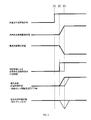
- FIG. 3 An operation example by such power supply control processing is shown in FIG. As shown in FIG. 3, when the ECU 32 transmits a drive command for the ISG 33 at timing [A], the ISG 33 that recognizes the drive command starts driving at timing [B] after timing [A], for example. Furthermore, the control amount set at timing [C] later than timing [B] is reached.
- the voltage of the first power supply system 2 to which the ISG 33 and the electrical load 37 are connected is from timing [B] to timing [C] as the ISG 33 consumes power. descend.
- the recognition value of the drive command by the control device 10A changes from 0 to 1 at timing [B]. That is, the control device 10A can recognize the drive command at timing [B].
- the control device 10A can send an instruction to change the power feeding state according to the voltage drop to the power feeding state adjusting unit 36, and the power feeding state of the electrical load 37 is approximately A constant state can be maintained. That is, the pressure of the fuel discharged by the fuel pump, which is the electrical load 37, is maintained substantially constant regardless of the voltage drop.
- the control device 10A changes the power supply state of the electric load 37 by detecting a parameter indicating a sign of voltage change such as a drive command to the ISG 33 at timing [B].
- a parameter indicating a sign of voltage change such as a drive command to the ISG 33 at timing [B].
- the voltage is directly monitored, for example, it can be detected that the voltage has actually changed at timing [C] later than timing [B].
- control device 10A can not send an instruction to change the power feeding state according to the voltage drop to the power feeding state adjusting unit 36 unless the timing [C] is reached, and the power feeding state of the electric load 37 May temporarily decrease the output. That is, the pressure of the fuel discharged by the fuel pump, which is the electrical load 37, is temporarily reduced due to the voltage drop, and then recovered when the power supply state is changed.
- the vehicle power supply system 1A described above includes the first battery 31, the second battery 41, the electrical load 37, and the control device 10A.
- the first battery 31 is connected to the first power system 2
- the second battery 41 is connected to the second power system 4 different from the first power system 2.
- the electrical load 37 is connected to the first power supply system 2.
- the control device 10A is connected to the second power supply system 4 which is a power supply system different from the electric load 37, acquires a parameter indicating a sign of a voltage change of the first power supply system 2, and responds to the sign indicated by the parameter. It is configured to set 37 power supply states.
- the control device 10A connected to the second power supply system 4 can recognize a change in voltage of the first power supply system 2 using a parameter indicating a sign of a voltage change.
- the power supply state of the electric load 37 can be set according to the change of the voltage. Therefore, it is possible to suppress an increase in cost and an increase in space by providing a delay due to communication and a dedicated line or the like for suppressing the delay.
- the above-described vehicle power supply system 1A further includes an ISG 33.
- the ISG 33 is connected to the first power supply system 2 and configured to consume or generate power.
- the control device 10A is configured to acquire, as a parameter indicating a sign of a voltage change, change information indicating that the operation state of the ISG 33 is to be changed.
- the power supply state of the electric load 37 is appropriately set in consideration of the voltage change due to the operation of the ISG 33. be able to.
- control device 10A is configured to acquire, as the change information, the fact that the requirement for operating the ISG 33 is established.
- the power supply state of the electric load 37 can be set by predicting that the potential of the first power supply system 2 changes depending on whether the requirement for operating the ISG 33 is satisfied. .
- control device 10A is configured to obtain, as change information, an operation amount request representing a request value of the operation amount to the ISG 33.
- the energy density of the first battery 31 is configured to be different from the energy density of the second battery 41.
- batteries with high energy density are excellent in performance but expensive.
- a vehicle power supply system 1A since a battery having a high energy density and a battery having a low energy density are combined and adopted for the vehicle power supply system 1A, if a power supply system to be connected is selected according to the application of the device, It is possible to balance the cost and performance of the battery.
- the voltage of the first battery 31 is configured to be different from the voltage of the second battery 41.
- a battery with a high voltage can be set to charge / discharge to a device with a high operating voltage, such as a generator for energy regeneration or traveling, and a battery with a low voltage is It can be set to charge / discharge to a device having a low operating voltage, such as an existing accessory device.
- the vehicle power supply system 1A further includes a DCDC converter 20.
- the DCDC converter 20 is configured to transform and connect the first power supply system 2 and the second power supply system 4.
- control device 10A is connected to the second power supply system 4 and configured to control the electric load 37 connected to the first power supply system 2.
- the control device 10B is connected to the first power supply system 2 and configured to control the electric load 47 connected to the second power supply system 4. , Is different from the first embodiment.
- the vehicle power supply system 1B of the second embodiment is, as shown in FIG. 4, in place of the control device 10A, the ECU 32, the power feeding state adjustment unit 36, and the electrical load 37 in the first embodiment.
- a state adjustment unit 46 and an electric load 47 are provided.
- control device 10B has the same configuration as the control device 10A, it is connected to the first power system 2.
- the feeding state adjustment unit 46 and the electric load 47 are connected to the second power supply system 4.
- the feed state adjusting unit 46 has the same configuration as the feed state adjusting unit 36, and adjusts the feed state of the electric load 47 according to a command from the control device 10B.
- the electric load 47 is configured as, for example, a steering motor or the like that assists the steering operation.
- the ECU 42 uses the starter 43 as a consumption generating unit, and transmits change information to the starter 43 to change the operation state of the starter 43, such as a drive request.
- the control device 10B is configured to be able to monitor change information.
- control device 10B controls the power supply state of the electrical load 47 by performing the same power supply control process as described above.
- a vehicle power supply system 1C according to the third embodiment includes a cutoff switch 25 as shown in FIG. 5 instead of the DCDC converter 20 according to the first embodiment.
- the first battery 31 in the vehicle power supply system 1C is configured as a lithium ion battery in which the rated voltage is set. That is, the rated voltage of the first battery 31 is set to 12V.
- the shutoff switch 25 is disposed between the first power supply line 3 of the first power supply system 2 and the second power supply line 5 of the second power supply system 4 and responds to an external command from any device such as the control device 10A. It switches between a state in which the first power supply line 3 and the second power supply line 5 are connected and a state in which the first power supply line 3 and the second power supply line 5 are divided.
- a vehicle power supply system 1D of the fourth embodiment is provided with a cutoff switch 25 as shown in FIG. 6 in place of the DCDC converter 20 in the vehicle power supply system 1B of the second embodiment.
- the first battery 31 in the vehicle power supply system 1D is configured as a lithium ion battery whose rated voltage is set to 12V.
- the present invention is not limited to this.
- an electrical device that controls the power supply state based on the power supply voltage can be applied.
- a fuel injection device such as an injector, a headlight, a blower fan, a heater, or a throttle by wire, a brake by wire, a steer by wire, etc. It may be adopted.
- the consumption generating unit may be any device configured to consume or generate power.
- a power steering device an electric air conditioner compressor, an electric supercharger or the like may be adopted as the consumption generating unit.
- the controlled unit may be a device that separates and connects a plurality of power supply systems, such as the DCDC converter 20 and the cutoff switch 25, or any device that is affected by the voltage of the power supply system.
- the multiple functions of one component in the above embodiment may be realized by multiple components, or one function of one component may be realized by multiple components. . Also, a plurality of functions possessed by a plurality of components may be realized by one component, or one function realized by a plurality of components may be realized by one component. In addition, part of the configuration of the above embodiment may be omitted. Further, at least a part of the configuration of the above-described embodiment may be added to or replaced with the configuration of the other above-described embodiment.
- the present disclosure can also be realized in various forms, such as a program for functioning, a non-transitional actual recording medium such as a semiconductor memory storing the program, and an operation control method of an electric device.
- control devices 10A and 10B in the above embodiment correspond to the parameter acquisition unit, the operation setting unit, and the power control device in the present disclosure
- the electric loads 37 and 47 in the above embodiment correspond to the controlled unit in the disclosure.
- the ISG 33 in the first embodiment and the third embodiment, and the starter 43 in the second embodiment and the fourth embodiment correspond to the consumption generating unit in the present disclosure.
- first power supply system 2 in the first embodiment and the third embodiment, and the second power supply system 4 in the second embodiment and the fourth embodiment correspond to the control destination system in the present disclosure
- second power supply system 4 in the embodiment and the third embodiment, and the first power supply system 2 in the second embodiment and the fourth embodiment correspond to the control source system in the present disclosure
- the process of S110 among the processes executed by the control devices 10A and 10B in the above embodiments corresponds to the acquisition unit in the present disclosure
- the processes of S140, S150, and S160 in the above embodiments are the present disclosure. It corresponds to a control setting part said.
Landscapes
- Engineering & Computer Science (AREA)
- Mechanical Engineering (AREA)
- Power Engineering (AREA)
- Transportation (AREA)
- Charge And Discharge Circuits For Batteries Or The Like (AREA)
- Electric Propulsion And Braking For Vehicles (AREA)
- Dc-Dc Converters (AREA)
Priority Applications (2)
| Application Number | Priority Date | Filing Date | Title |
|---|---|---|---|
| CN201880061188.7A CN111149270B (zh) | 2017-09-22 | 2018-09-21 | 车辆电源系统及电源控制装置 |
| US16/826,435 US11225210B2 (en) | 2017-09-22 | 2020-03-23 | Vehicle power supply system and power supply control device |
Applications Claiming Priority (2)
| Application Number | Priority Date | Filing Date | Title |
|---|---|---|---|
| JP2017-182553 | 2017-09-22 | ||
| JP2017182553 | 2017-09-22 |
Related Child Applications (1)
| Application Number | Title | Priority Date | Filing Date |
|---|---|---|---|
| US16/826,435 Continuation US11225210B2 (en) | 2017-09-22 | 2020-03-23 | Vehicle power supply system and power supply control device |
Publications (1)
| Publication Number | Publication Date |
|---|---|
| WO2019059361A1 true WO2019059361A1 (ja) | 2019-03-28 |
Family
ID=65811353
Family Applications (1)
| Application Number | Title | Priority Date | Filing Date |
|---|---|---|---|
| PCT/JP2018/035128 Ceased WO2019059361A1 (ja) | 2017-09-22 | 2018-09-21 | 車両電源システム、および電源制御装置 |
Country Status (4)
| Country | Link |
|---|---|
| US (1) | US11225210B2 (https=) |
| JP (1) | JP6822456B2 (https=) |
| CN (1) | CN111149270B (https=) |
| WO (1) | WO2019059361A1 (https=) |
Cited By (1)
| Publication number | Priority date | Publication date | Assignee | Title |
|---|---|---|---|---|
| WO2024166612A1 (ja) * | 2023-02-10 | 2024-08-15 | 株式会社デンソー | スイッチ遮断装置、及びプログラム |
Families Citing this family (2)
| Publication number | Priority date | Publication date | Assignee | Title |
|---|---|---|---|---|
| JP7820953B2 (ja) * | 2021-11-16 | 2026-02-26 | 株式会社Subaru | 車両 |
| CN115257588B (zh) * | 2022-06-22 | 2024-09-13 | 中国第一汽车股份有限公司 | 换挡执行器供电保护方法、装置以及电子设备 |
Citations (2)
| Publication number | Priority date | Publication date | Assignee | Title |
|---|---|---|---|---|
| JP5106632B2 (ja) * | 2008-06-17 | 2012-12-26 | 三菱電機株式会社 | エンジン制御装置 |
| JP2014045631A (ja) * | 2012-08-29 | 2014-03-13 | Nissan Motor Co Ltd | Dc−dcコンバータの制御装置 |
Family Cites Families (17)
| Publication number | Priority date | Publication date | Assignee | Title |
|---|---|---|---|---|
| JP3861321B2 (ja) * | 1996-05-02 | 2006-12-20 | トヨタ自動車株式会社 | ハイブリッド車 |
| JP3381708B2 (ja) * | 2000-05-02 | 2003-03-04 | トヨタ自動車株式会社 | 車両、電源系制御装置、電源系を制御する方法および車両の始動時制御方法 |
| DE10296683T5 (de) * | 2001-12-21 | 2004-04-22 | Aisin AW Co., Ltd., Anjo | Antriebssteuerungsgerät für ein motorbetriebenes Fahrzeug |
| JP3812459B2 (ja) * | 2002-02-26 | 2006-08-23 | トヨタ自動車株式会社 | 車両の電源制御装置 |
| US7336002B2 (en) * | 2003-02-17 | 2008-02-26 | Denso Corporation | Vehicle power supply system |
| JP4910482B2 (ja) * | 2006-05-25 | 2012-04-04 | トヨタ自動車株式会社 | 可変動弁装置、その制御方法及びこれを搭載した車両 |
| JP2009106021A (ja) * | 2007-10-22 | 2009-05-14 | Toyota Motor Corp | 回転電機制御装置 |
| EP2272722B1 (en) * | 2009-07-01 | 2015-04-08 | Denso Corporation | Power source apparatus for vehicle |
| JP2013116703A (ja) * | 2011-12-05 | 2013-06-13 | Denso Corp | 車両用電力管理システム、車両用電力情報管理装置、及び車両用電気負荷 |
| US9682673B2 (en) * | 2012-03-23 | 2017-06-20 | Sanyo Electric Co., Ltd. | Vehicle power source device and vehicle equipped with the power source device |
| WO2014068918A1 (ja) * | 2012-10-29 | 2014-05-08 | 三洋電機株式会社 | 車両用電源装置 |
| JP2015027198A (ja) * | 2013-07-26 | 2015-02-05 | 株式会社東芝 | 半導体集積回路および電源管理システム |
| DE112013007438B4 (de) * | 2013-09-17 | 2025-10-16 | Mitsubishi Electric Corporation | Elektrische Speichervorrichtung für ein Fahrzeug |
| JP6107591B2 (ja) | 2013-10-18 | 2017-04-05 | 株式会社オートネットワーク技術研究所 | 車両電源システム |
| JP2015217919A (ja) * | 2014-05-21 | 2015-12-07 | オムロンオートモーティブエレクトロニクス株式会社 | 車両用電源装置、車両用回生システム |
| JP2016141356A (ja) * | 2015-02-05 | 2016-08-08 | 株式会社オートネットワーク技術研究所 | 自動車用電源装置及び自動車用電源装置の制御方法 |
| JP2017135947A (ja) | 2016-01-29 | 2017-08-03 | トヨタ自動車株式会社 | 車両用制御装置 |
-
2018
- 2018-09-21 JP JP2018177689A patent/JP6822456B2/ja active Active
- 2018-09-21 CN CN201880061188.7A patent/CN111149270B/zh active Active
- 2018-09-21 WO PCT/JP2018/035128 patent/WO2019059361A1/ja not_active Ceased
-
2020
- 2020-03-23 US US16/826,435 patent/US11225210B2/en active Active
Patent Citations (2)
| Publication number | Priority date | Publication date | Assignee | Title |
|---|---|---|---|---|
| JP5106632B2 (ja) * | 2008-06-17 | 2012-12-26 | 三菱電機株式会社 | エンジン制御装置 |
| JP2014045631A (ja) * | 2012-08-29 | 2014-03-13 | Nissan Motor Co Ltd | Dc−dcコンバータの制御装置 |
Cited By (1)
| Publication number | Priority date | Publication date | Assignee | Title |
|---|---|---|---|---|
| WO2024166612A1 (ja) * | 2023-02-10 | 2024-08-15 | 株式会社デンソー | スイッチ遮断装置、及びプログラム |
Also Published As
| Publication number | Publication date |
|---|---|
| CN111149270B (zh) | 2023-10-31 |
| JP2019059466A (ja) | 2019-04-18 |
| US11225210B2 (en) | 2022-01-18 |
| CN111149270A (zh) | 2020-05-12 |
| JP6822456B2 (ja) | 2021-01-27 |
| US20200216003A1 (en) | 2020-07-09 |
Similar Documents
| Publication | Publication Date | Title |
|---|---|---|
| CN109941088B (zh) | 混合动力汽车以及混合动力汽车的控制方法 | |
| US9895994B2 (en) | Vehicle control system | |
| CA2911941C (en) | Vehicle driven by electric motor and control method for vehicle | |
| WO2017211035A1 (zh) | 增程式电动车辆及其能量管理控制方法和装置 | |
| JP2015226341A (ja) | 電源制御装置および電源制御方法 | |
| JP2015217919A (ja) | 車両用電源装置、車両用回生システム | |
| EP3725581A1 (en) | Regenerative braking control method and regenerative braking control device | |
| US9871480B2 (en) | Power supply control apparatus, vehicle and method of controlling power supply | |
| CN106794771B (zh) | 车载电路组件和用于使可利用燃料电池电驱动的交通工具的车载电路运行的方法 | |
| JP2015217920A (ja) | 車両用電源装置、車両用回生システム | |
| US20190299968A1 (en) | Control apparatus | |
| CN102452393A (zh) | 串联式混合动力车辆的控制装置 | |
| US20190299973A1 (en) | Control apparatus | |
| US10910972B2 (en) | Control apparatus and onboard system | |
| US11225210B2 (en) | Vehicle power supply system and power supply control device | |
| JP2019030189A (ja) | 電源システム | |
| JP6577981B2 (ja) | 電源システム | |
| JP2016141356A (ja) | 自動車用電源装置及び自動車用電源装置の制御方法 | |
| US11447121B2 (en) | Control apparatus and control method for hybrid system of vehicle | |
| CN103097171B (zh) | 用于驱动汽车的恢复系统中的发电机的方法和设备 | |
| CN110337397B (zh) | 车辆系统 | |
| KR101826674B1 (ko) | 차량에서의 리저브 토크 확보 방법 | |
| US8922036B2 (en) | Vehicular power generation system and power generation control method for the same | |
| JP2015150958A (ja) | 車両用電池システム | |
| US20110144837A1 (en) | Hybrid accessory power module shedding for high voltage battery protection |
Legal Events
| Date | Code | Title | Description |
|---|---|---|---|
| 121 | Ep: the epo has been informed by wipo that ep was designated in this application |
Ref document number: 18859819 Country of ref document: EP Kind code of ref document: A1 |
|
| NENP | Non-entry into the national phase |
Ref country code: DE |
|
| 122 | Ep: pct application non-entry in european phase |
Ref document number: 18859819 Country of ref document: EP Kind code of ref document: A1 |