WO2019056717A1 - 一种后张预应力装配砼框架抗震耗能构件体系及施工方法 - Google Patents
一种后张预应力装配砼框架抗震耗能构件体系及施工方法 Download PDFInfo
- Publication number
- WO2019056717A1 WO2019056717A1 PCT/CN2018/079982 CN2018079982W WO2019056717A1 WO 2019056717 A1 WO2019056717 A1 WO 2019056717A1 CN 2018079982 W CN2018079982 W CN 2018079982W WO 2019056717 A1 WO2019056717 A1 WO 2019056717A1
- Authority
- WO
- WIPO (PCT)
- Prior art keywords
- concrete
- main beam
- shear wall
- frame
- layer
- Prior art date
Links
Images


Classifications
-
- E—FIXED CONSTRUCTIONS
- E04—BUILDING
- E04B—GENERAL BUILDING CONSTRUCTIONS; WALLS, e.g. PARTITIONS; ROOFS; FLOORS; CEILINGS; INSULATION OR OTHER PROTECTION OF BUILDINGS
- E04B1/00—Constructions in general; Structures which are not restricted either to walls, e.g. partitions, or floors or ceilings or roofs
- E04B1/18—Structures comprising elongated load-supporting parts, e.g. columns, girders, skeletons
- E04B1/20—Structures comprising elongated load-supporting parts, e.g. columns, girders, skeletons the supporting parts consisting of concrete, e.g. reinforced concrete, or other stonelike material
- E04B1/22—Structures comprising elongated load-supporting parts, e.g. columns, girders, skeletons the supporting parts consisting of concrete, e.g. reinforced concrete, or other stonelike material with parts being prestressed
-
- E—FIXED CONSTRUCTIONS
- E04—BUILDING
- E04H—BUILDINGS OR LIKE STRUCTURES FOR PARTICULAR PURPOSES; SWIMMING OR SPLASH BATHS OR POOLS; MASTS; FENCING; TENTS OR CANOPIES, IN GENERAL
- E04H9/00—Buildings, groups of buildings or shelters adapted to withstand or provide protection against abnormal external influences, e.g. war-like action, earthquake or extreme climate
- E04H9/02—Buildings, groups of buildings or shelters adapted to withstand or provide protection against abnormal external influences, e.g. war-like action, earthquake or extreme climate withstanding earthquake or sinking of ground
- E04H9/021—Bearing, supporting or connecting constructions specially adapted for such buildings
-
- E—FIXED CONSTRUCTIONS
- E04—BUILDING
- E04B—GENERAL BUILDING CONSTRUCTIONS; WALLS, e.g. PARTITIONS; ROOFS; FLOORS; CEILINGS; INSULATION OR OTHER PROTECTION OF BUILDINGS
- E04B2/00—Walls, e.g. partitions, for buildings; Wall construction with regard to insulation; Connections specially adapted to walls
- E04B2/56—Load-bearing walls of framework or pillarwork; Walls incorporating load-bearing elongated members
- E04B2/562—Load-bearing walls of framework or pillarwork; Walls incorporating load-bearing elongated members with fillings between the load-bearing elongated members
-
- E—FIXED CONSTRUCTIONS
- E04—BUILDING
- E04B—GENERAL BUILDING CONSTRUCTIONS; WALLS, e.g. PARTITIONS; ROOFS; FLOORS; CEILINGS; INSULATION OR OTHER PROTECTION OF BUILDINGS
- E04B5/00—Floors; Floor construction with regard to insulation; Connections specially adapted therefor
- E04B5/16—Load-carrying floor structures wholly or partly cast or similarly formed in situ
- E04B5/17—Floor structures partly formed in situ
-
- E—FIXED CONSTRUCTIONS
- E04—BUILDING
- E04C—STRUCTURAL ELEMENTS; BUILDING MATERIALS
- E04C3/00—Structural elongated elements designed for load-supporting
- E04C3/02—Joists; Girders, trusses, or trusslike structures, e.g. prefabricated; Lintels; Transoms; Braces
- E04C3/20—Joists; Girders, trusses, or trusslike structures, e.g. prefabricated; Lintels; Transoms; Braces of concrete or other stone-like material, e.g. with reinforcements or tensioning members
- E04C3/26—Joists; Girders, trusses, or trusslike structures, e.g. prefabricated; Lintels; Transoms; Braces of concrete or other stone-like material, e.g. with reinforcements or tensioning members prestressed
-
- E—FIXED CONSTRUCTIONS
- E04—BUILDING
- E04C—STRUCTURAL ELEMENTS; BUILDING MATERIALS
- E04C3/00—Structural elongated elements designed for load-supporting
- E04C3/30—Columns; Pillars; Struts
- E04C3/34—Columns; Pillars; Struts of concrete other stone-like material, with or without permanent form elements, with or without internal or external reinforcement, e.g. metal coverings
Definitions
- the invention belongs to the field of fabricated concrete structure construction, in particular to a post-tensioned prestressed assembly truss frame seismic energy-consuming component system and a construction method.
- the prestressing tendons usually run through multiple spans and are anchored only by the anchors at both ends. When one end anchor fails, the whole prestressed tendons will lose tension, and the crimping effect of the associated beam-column joints will cease to exist.
- the structural robust performance is not high. 3.
- the large-plate structure without secondary beams is usually used. When there is local concentrated load, the structure is complicated and the construction is difficult. 4.
- the stiffness of the conventional pre-stressed dry-type pure frame system is weaker than that of the assembly. The applicable height in the high-intensity zone is limited according to the current specifications. 5.
- the object of the present invention is to provide a system and a construction method for a post-tensioned prestressed assembly truss frame seismic energy-consuming component, and to solve the problem of large transportation and hoisting in the existing structural system under the premise of ensuring better seismic performance.
- the technical problem is that the robust performance is not high, the wet work volume is large, the construction is complicated, the repair cost of the column foot after the earthquake is high, and the energy-consuming steel bar is disposed in the beam with high cost and complicated production.
- the present invention adopts the following technical solutions.
- a post-tensioned prestressed assembled truss frame seismic energy-consuming component system comprising a foundation, a frame column, a laminated main beam, and a seismic energy-consuming member filled in a rectangular frame enclosed by the frame column and the laminated main beam And superposed slabs;
- the frame columns are arranged in a layered manner, and a spacing is left between the adjacent frame columns of the upper and lower layers; a horizontal column prestressing channel is disposed at an upper portion of the frame column near the top end; the top of the frame column is reserved Vertical reinforcement, wherein the upper end of the vertical reinforcement exceeds the top of the concrete connection layer and is connected with the frame column above it; a concrete connection layer is poured in the space between the adjacent frame columns of the upper and lower layers;
- the superposed main beam comprises a precast concrete main beam and a main beam concrete superposed layer;
- the precast concrete main beam is connected to the frame column, the side of the prestressed tunnel is provided, and the top surface of the precast concrete main beam Aligning with the top surface of the frame column;
- the pre-concrete main beam the position corresponding to the pre-stressed channel of the column, and the beam pre-stressed hole along the axial direction;
- the precast concrete main beam and the frame column pass a prestressed steel wire bundle connected in the beam prestressing tunnel and the column prestressing tunnel;
- the main beam concrete laminated layer is cast on the top of the precast concrete main beam, between two adjacent laminated slabs, and the main beam concrete
- the thickness of the laminated layer is adapted to the thickness of the concrete connecting layer;
- the laminated floor slab comprises a prefabricated hollow slab and a slab concrete laminated layer cast on the top of the prefabricated hollow slab, wherein the top surface of the slab concrete laminated layer is flush with the top surface of the main beam concrete laminated layer;
- the prestressed steel wire bundle is located in the prefabricated concrete beam span portion of the prestressed steel wire bundle having a bonding section, and the prestressed steel wire bundle is located on both sides of the precast concrete beam as a prestressed steel wire bundle non-bonding section; wherein the prestressed steel wire
- the length of the bundle having the bonding section is 2m to 3m;
- the seismic energy-consuming member is an earthquake-resistant wall;
- the seismic wall comprises a shear-type energy damper and a shear wall, a bottom of the shear wall and a laminated main beam below it or a shear wall and a foundation They are connected by a vertical casing grout connection or a dry connection.
- the frame column is disposed between the foundation and the laminated floor slab or between the two adjacent slabs; the connection frame is reserved at the position where the frame column is connected; the frame A reinforcing steel connecting sleeve is arranged at the bottom of the column; the frame column and the foundation are connected by a connecting steel bar and a steel connecting sleeve, and the two upper and lower frame columns are connected by a vertical reinforcing bar and a steel connecting sleeve.
- the outer side of the root of the lowermost frame column is provided with an outer steel plate; the height of the outer steel plate is 1 to 3 times of the long side of the horizontal section of the frame column, and the thickness of the outer steel plate is 10 mm to 30 mm.
- the concrete connecting layer is provided with horizontal energy-consuming steel bars and shear reinforcing steel bars; the energy-consuming steel bars are located at the top of the concrete connecting layer, and the two ends thereof respectively extend into the main beam concrete overlapping layers on both sides
- the energy-consuming steel bar is composed of a consumable section of the energy-consuming steel bar and an unbonded section of the energy-consuming steel bar; wherein the unbonded section of the energy-consuming steel bar is disposed in the composite layer of the main beam concrete, close to the side of the concrete connecting layer or set In the concrete connecting layer; the area of the reinforcing bar in the unbonded section of the energy-consuming steel bar is smaller than the area of the reinforcing bar in the bonded section of the energy-consuming steel bar, and the length of the unbonded section of the energy-consuming steel bar is 3-20 in the diameter of the energy-consuming steel bar. Times
- the shear reinforcement is located at the bottom of the concrete connection layer, and its two ends respectively extend into the main beam concrete laminate layers on both sides.
- a superimposed secondary beam is disposed between two adjacent superposed main beams;
- the superposed secondary girder includes a precast concrete secondary beam, a secondary beam concrete laminated layer, and a secondary beam laminated layer reinforcing bar;
- the top of the concrete secondary beam is flush with the top of the precast concrete main beam;
- the secondary beam concrete laminated layer is poured on the top of the precast concrete secondary beam, between the adjacent two overlapping slabs, and the secondary beam concrete laminated layer
- the thickness is adapted to the thickness of the laminated layer of the main beam concrete;
- the secondary beam laminated layer is arranged on the top of the secondary beam concrete laminated layer, and the two ends are respectively anchored in the main beam concrete laminated layer on both sides.
- the prefabricated hollow slab in the laminated slab is a prefabricated circular orifice plate or a prefabricated shaped orifice plate or an SP plate; the laminated slab is further provided with a slab structure reinforcement bar and a plate additional reinforcement bar, wherein the slab structure reinforcement bar
- the mesh steel bars are horizontally arranged in the floor concrete laminated layer near the top position; the additional steel bars are placed in the holes of the prefabricated hollow plates or at the gaps between the plates of the prefabricated hollow plates, and are located at the gaps between the plates
- the two ends of the additional steel bars are respectively poured into the holes of the prefabricated hollow plates on both sides of the slit.
- the shear wall is integrally formed; a vertical sleeve is arranged at a bottom of the shear wall, a bottom of the shear wall and a laminated main beam below it or a shear wall and foundation The joint is grouted through a vertical casing; the shear type energy damper is installed between the top of the shear wall and the bottom of the laminated main beam, and connects the shear wall to the superposed main beam above it.
- the shear wall comprises an upper shear wall unit and a lower shear wall unit; wherein the top of the upper shear wall unit is connected with the superposed main beam above the dry main beam;
- the shear wall unit is connected with the underlying main beam or between the lower shear wall unit and the foundation by a dry connection;
- the shear type energy damper is connected to the upper shear wall unit and the lower Shear between wall units.
- a construction method for a post-tensioned prestressed assembled truss frame seismic energy consuming member system comprising the following steps.
- Step 1 Produce prefabricated components in the factory, including production of frame columns, precast concrete girder, prefabricated hollow slabs, and seismic energy consuming components.
- Step 2 Install the frame column of the floor to be constructed.
- a temporary supporting cow leg is installed on the side of the frame column corresponding to the bottom surface of the precast concrete main beam, and temporary support is installed below the position of the overlapping main beam.
- Step 4 hoisting and temporarily fixing the seismic energy-consuming components.
- step 5 the precast concrete main beam is hoisted; the two ends of the precast concrete main beam are placed on the supporting bull's leg, and the mid-span of the precast concrete main beam is supported on the temporary support below.
- Step 6 hoisting the precast concrete secondary beam; suspending the precast concrete secondary beam between two adjacent precast concrete main beams, and connecting the two ends thereof to the two precast concrete main beams;
- Step 7 Set the temporary support at the bottom of the laminated floor and hoist the prefabricated hollow slab.
- Step 8 strip the prestressed steel wire bundle in the prestressed steel wire bundle with the wire bundle casing outside the bonding section, remove the oil stain on the surface of the bonding section of the prestressed steel wire bundle, and penetrate the prestressed steel wire bundle into the beam prestressing The tunnel and the column are prestressed in the tunnel.
- Step 9 Fill the joints of the beams and columns formed after the completion of the construction in step 5 with high-strength fiber mortar, and fill it with solid.
- Step 10 After the high-strength fiber mortar reaches the design strength, the pre-stressed steel wire bundle is tensioned and anchored.
- Step 11 Laying the slab concrete laminate layer, the main beam concrete laminate layer and the secondary beam concrete laminate layer.
- Step 12 Casting the concrete of the slab concrete laminated layer, the concrete of the main beam concrete laminated layer and the concrete of the secondary beam concrete laminated layer.
- Step 13 Inject high-strength grout into the beam prestressing channel and the column prestressing channel through which the prestressed wire bundle passes.
- Step 14 Repeat steps 2 to 13 for each layer until the frame portion of the post-tensioned prestressed assembly frame seismic energy-consuming component system is completely installed.
- Step 15 Connect the seismic energy-consuming components to the precast concrete main beam to complete the construction of the system.
- step 2 when the frame column of the floor to be constructed is connected with the foundation, the steel connecting sleeve at the bottom of the lowermost frame column is correspondingly sleeved on the basic connecting steel bar, and temporarily fixed to adjust the axial position of the frame column. And the verticality, and then grouting at the seam of the lowermost frame column and the foundation;
- the shear wall is firstly connected to the laminated main beam or the foundation below by vertical grouting; and then the shearing is installed on the top of the shear wall.
- the type of energy consuming device and the superposed main beam above it are fixedly connected by a dry connecting member;
- the shear wall is a shear wall comprising an upper shear wall unit and a lower shear wall unit; a dry connection between the lower shear wall unit and the superposed main beam or foundation below it is first used The piece is connected, and the shear type energy damper is fixedly connected in the middle of the top of the lower shear wall unit, and then the dry connection is connected between the top of the upper shear wall unit and the superposed main beam above the upper shear wall unit, and the upper shear is connected The bottom of the force wall unit is fixedly connected with the dry connector.
- the post-tensioned pre-stressed truss frame seismic energy-consuming component system of the present invention is a system which is convenient for transportation and hoisting, has good robustness, high construction efficiency, good seismic performance and easy repair after earthquake.
- the invention improves the construction speed of the system by optimizing the selection of the prefabricated components such as the frame column, the prefabricated seismic wall, the laminated main beam, the laminated slab, the connection structure, and the reasonable arrangement of the construction process. And green construction level.
- the frame column of the invention is layered, which greatly reduces the technical difficulty of transportation and lifting during the construction of the frame column, and the invention fills the seismic energy-consuming component in the rectangular frame enclosed by the frame column and the laminated main beam.
- the lateral stiffness of the pure frame system is improved, and the double anti-side force system or the second line of defense is formed.
- the application range of the prefabricated prestressed frame structure is expanded, and it can be used for higher public buildings in the high intensity area. Such as schools, office buildings, apartments, hospitals, etc.
- the prestressed steel wire bundle of the present invention is a post-tensioned prestressed steel wire bundle comprising a prestressed steel wire bundle having a bonding section and a prestressed steel wire bundle unbonded section; the prestressed steel wire bundle having a bonding section at each of the
- the prefabricated concrete main beam is partially arranged across the middle, and its length is 2m ⁇ 3m.
- a prestressed anchor fails, the whole prestressed tendon will not lose tension, and the node that loses the crimping force is limited to failure.
- the span of the anchor is increased to improve the ability of the structure to prevent continuous collapse.
- the invention introduces a simple superimposed secondary beam between the superposed main beams, which solves the problem that the structural slab is complicated when the local concentrated load such as the partition wall and the girders on the beam is large.
- the frame column and the foundation are connected by a connecting steel bar and a steel bar connecting sleeve, wherein the connecting steel bar is provided with a partial non-stick segment for the vertical side located in the foundation, and the length of the base steel bar without the bonding segment is the connection.
- the diameter of the steel bar is 3 to 20 times; the use of the post-tensioned prestressed steel wire bundle passing through the beam-column joints reduces the damage of the concrete structural members during the earthquake and increases the ability of the structure to resist earthquake damage.
- the invention achieves the purpose of improving the seismic performance of the whole system by setting the energy-consuming steel bar at the position of the overlapping main beam and the frame column node, thereby achieving the difficulty of the construction and construction.
- the invention only installs energy-consuming steel bars in the superposed concrete layer of the upper beam of the superimposed main beam, and the joints in the column are relatively reduced, thereby simplifying the construction of the joint nodes of the superimposed main beam and the frame column without overlapping
- the main beam is equipped with high-cost and complex construction energy-saving steel reserved troughs, which simplifies the prefabricated concrete joint structure; in addition, the energy-consumption steel and beam concrete laminated layer and floor concrete composite layer are simultaneously constructed, comprehensive Considering the connection relationship between the frame column and the laminated floor, the connection performance is better.
- the construction method of assembling the prefabricated hollow slab and the prestressed laminated main beam in the laminated slab of the invention makes the on-site construction convenient and quick, and only needs temporary support under the laminated main beam, which saves compared with the traditional prefabricated assembly structure. A large amount of support has improved the efficiency of construction and construction.
- FIG. 1 is a schematic view showing the main components of a system in which a seismic energy absorbing member is an earthquake resistant wall.
- FIG. 2 is a schematic view of a frame column and a base, laminated main beam connection structure in the present invention.
- Fig. 3 is a schematic view showing the connection node of the frame column and the overlapping main beam when the unbonded section of the energy-consuming steel bar is disposed outside the frame column and the frame column is the center column.
- FIG. 4 is a schematic view showing the connection node of the frame column and the overlapping main beam when the unbonded section of the energy-consuming steel bar is disposed outside the frame column and the frame column is the side column.
- Fig. 5 is a schematic view showing the connection node of the frame column and the overlapping main beam when the unbonded section of the energy-consuming steel bar is disposed in the frame column and the frame column is the center column.
- Fig. 6 is a schematic view showing the connection node of the frame column and the overlapping main beam when the unbonded section of the energy-consuming steel bar is disposed in the frame column and the frame column is the side column.
- Figure 7 is a schematic view showing the structure of a joint node of a laminated secondary beam and a laminated main beam in the present invention.
- Fig. 8 is a structural schematic view showing the overlapping main beam and the laminated floor joint of the laminated floor in the secondary direction of the present invention.
- Figure 9 is a schematic view showing the structure of the superposed main beam and the superposed floor slab in the main force direction of the laminated slab in the present invention.
- Fig. 10 is a structural schematic view showing the shear-resistant wall of the present invention in which the seismic energy-consuming member is integrally formed.
- Figure 11 is a cross-sectional view taken along line A-A of Figure 10 of the present invention.
- Figure 12 is a schematic view showing the structure of the shear wall of the seismic wall according to the present invention when it is divided into an upper shear wall unit and a lower shear wall unit.
- Figure 13 is a cross-sectional view taken along line B-B of Figure 12 of the present invention.
- Fig. 14 is a view showing the main components of the system in which the seismic energy absorbing member of the present invention is supported by steel.
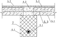
- the post-tensioned prestressed assembled truss frame seismic energy consuming member system comprises a foundation 1, a frame column 2, and a laminated main beam 4, which are filled in a rectangular frame surrounded by the frame column 2 and the laminated main beam 4. Seismic energy consuming members and laminated slabs 5; the frame columns 2 are arranged in a layered manner, and a space is left between the upper and lower adjacent frame columns 2; the upper portion of the frame columns 2 is horizontally disposed near the top end a column prestressing channel 2.1; a vertical reinforcing bar 2.2 is reserved at the top of the frame column 2, wherein the upper end of the vertical reinforcing bar 2.2 extends beyond the top of the concrete connecting layer 10 and is connected to the frame column 2 above it; adjacent to the upper and lower layers a concrete connection layer 10 is poured in the space between the frame columns 2;
- the laminated main beam 4 includes a precast concrete main beam 4.1 and a main beam concrete superposed layer 4.2; the precast concrete main beam 4.1 is connected to the frame column 2, and the column prestress is provided.
- One side of the tunnel 2.1, and the top surface of the precast concrete main beam 4.1 is flush with the top surface of the frame column 2; the precast concrete main beam 4.1 is located at the position corresponding to the prestressing tunnel 2.1 of the column, and is arranged along the axial direction.
- This structure makes the structure have a certain self-recovery ability after the earthquake; the main beam concrete superposed layer 4.2 is poured on the top of the precast concrete main beam 4.1, and the adjacent two laminated slabs 5 Between, and the thickness of the main beam concrete superposed layer 4.2 is adapted to the thickness of the concrete connecting layer 10; the splicing position of the adjacent frame columns 2 of the upper and lower layers is generally located at the structural elevation of the floor.
- the laminated floor panel 5 comprises a precast hollow panel 5.1 and a slab concrete laminate layer 5.2 cast on top of the precast hollow panel 5.1, wherein the top surface of the slab concrete laminate layer 5.2 It is flush with the top surface of the main beam concrete laminate layer 4.2.
- the prestressed steel wire bundle 7 is a post-tensioned prestressed steel wire bundle, comprising a prestressed steel wire bundle having a bonding section 7.1 and a prestressed steel wire bundle unbonded section 7.2; the prestressed steel wire bundle is viscous
- the joint 7.1 is partially disposed in the middle of each precast concrete main beam 4.1, and its length is 2m ⁇ 3m; in the extreme case, when a prestressed anchor fails, the whole prestressed steel wire bundle 7 will not lose tension.
- the node that loses the crimping force is limited to the span where the failed anchor is located, and the structure has a good ability to prevent continuous collapse.
- the frame column 2 may be disposed between the foundation 1 and the laminated floor panel 5, or may be disposed between the upper and lower adjacent laminate floor panels 5;
- a connection reinforcing bar 1.1 is reserved at a position connected to the frame column 2;
- a reinforcing bar connecting sleeve 2.3 is arranged at the bottom of the frame column 2;
- the frame column 2 and the base 1 are connected by a reinforcing bar 1.1 and a reinforcing bar connecting sleeve 2.3 Connected, wherein the connecting steel bar 1.1 is located in the base 1 and the base steel bar has no bonding section, the length of the non-bonding section of the base steel bar is 3-20 times of the diameter of the connecting steel bar 1.1;
- the vertical reinforcing bar 2.2 is connected to the reinforcing steel connecting sleeve 2.3 by inserting; wherein the outermost steel frame 12 is provided with an outer steel plate 12; the height of the outer steel plate 12
- the non-bonding section of the base steel bar is disposed at the position of the foundation 1 and the base 1 and the bottom frame column 2, and the non-bonded section of the base steel bar is subjected to 20% area weakening treatment, and is wrapped with plastic. After the pouring of the foundation 1 concrete.
- the concrete connecting layer 10 is provided with a horizontal energy-consuming steel bar 8 and a shear reinforcing bar 9; the energy-consuming steel bar 8 is located at the top of the concrete connecting layer 10, and its two ends extend into the two sides respectively.
- the main beam concrete composite layer 4.2; the energy-consuming steel bar 8 is composed of the energy-consuming steel bar bonded section 8.1 and the energy-consuming steel bar unbonded section 8.2; wherein the energy-consuming steel bar unbonded section 8.2 is set in the main beam concrete In the laminated layer 4.2, close to the side of the concrete connecting layer 10 or in the concrete connecting layer 10; the area of the reinforcing bar of the unbonded section 8.2 of the energy-consuming steel bar is smaller than the area of the reinforcing bar having the bonding section 8.1 of the energy-consuming steel bar,
- the length of the energy-free steel bar unbonded section 8.2 is 3 to 20 times the diameter of the energy-consuming steel bar 8; the shear-resistant steel bar 9 is located at the bottom of the concrete connecting layer 10, and the two ends of the energy-reinforcing steel bar respectively extend into the main beam concrete stack on both sides In layer 4.2.
- the energy-consuming steel bars 8 in the joint main beam 4 and the frame column 2 can be non-stick outside the column, that is, the energy-consuming steel bar unbonded section 8.2 is disposed in the beam, close to Beam and column connection interface side;
- the energy-consuming steel bars 8 in the joint main beam 4 and the frame column 2 can also be non-sticky in the column, that is, the portion of the energy-consuming steel bar 8 located in the frame column 2 is energy-consuming steel bar.
- Unbonded section 8.2 the portion outside the frame column 2 is poured into the main beam concrete stacking layer 4.2.
- a superimposed secondary beam 6 may be disposed between the adjacent two overlapping main beams 4 at a position corresponding to the partition wall;
- the beam 6 comprises a precast concrete secondary beam 6.1, a secondary beam concrete composite layer 6.2 and a secondary beam composite layer reinforcement 6.3; the top of the precast concrete secondary beam 6.1 is flush with the top of the precast concrete main beam 4.1; the secondary beam
- the concrete composite layer 6.2 is poured between the top of the precast concrete secondary beam 6.1 and the adjacent two laminated slabs 5, and the thickness of the secondary beam concrete superposed layer 6.2 is adapted to the thickness of the main beam concrete superposed layer 4.2;
- the secondary beam laminated layer steel 6.3 is arranged on the top of the secondary beam concrete composite layer 6.2, and its two ends are respectively anchored in the main beam concrete superposed layer 4.2 on both sides.
- the prefabricated hollow plate 5.1 in the laminated floor panel 5 may be a prefabricated circular orifice plate, a prefabricated shaped orifice plate or an SP plate; and the laminated floor panel 5 is further provided with a plate surface reinforcement bar. 5.4 and the board additional steel reinforcement 5.3, wherein the slab structure steel reinforcement 5.4 is a mesh steel reinforcement, horizontally arranged in the slab concrete composite layer 5.2, near the top position; the board additional reinforcement 5.3 is parallel to the main force direction of the laminated floor slab 5
- the holes are inserted in the holes of the prefabricated hollow plate 5.1 or at the gaps between the plates of the prefabricated hollow plate 5.1, and the ends of the additional steel bars 5.3 at the gaps between the plates are respectively cast into the holes of the precast hollow plate 5.1 on both sides of the gap.
- the seismic energy consuming member is an earthquake resistant wall 3;
- the seismic wall 3 includes a shear type energy consuming device 3.2 and a shear wall body 3.3;
- the shear wall body 3.3 is integrally formed with a vertical sleeve 3.1 at the bottom of the shear wall 3.3, between the bottom of the shear wall 3.3 and the superposed main beam 4 below or between the shear wall 3.3 and the foundation 1.
- the grouting connection is made by a vertical casing 3.1; the shearing type energy consuming device 3.2 is mounted on the top of the shear wall 3.3, and the shearing wall 3.3 is connected to the superposed main beam 4 above it; in other embodiments, The bottom of the shear wall 3.3 and the superposed main beam 4 below it or between the shear wall 3.3 and the foundation 1 can also be connected by a dry connection 14.
- the dry connector 14 is a bolted connection.
- the shear wall 3.3 may also be composed of an upper shear wall unit and a lower shear wall unit, wherein the top of the upper shear wall unit and the top thereof
- the main girder 4 is connected by a dry connecting member 14;
- the lower shearing wall unit is connected with the lower laminated main beam 4 or the lower shearing wall unit and the foundation 1 by a dry connecting member 14;
- the shear type energy consuming device 3.2 is connected between the upper shear wall unit and the lower shear wall unit.
- the construction method of the post-tensioned prestressed assembly truss frame seismic energy consuming member system includes the following steps.
- prefabricated components are produced in the factory, including the production of frame columns 2, precast concrete main beams 4.1, prefabricated hollow plates 5.1, precast concrete secondary beams 6.1 and prefabricated seismic walls 3.
- Step 2 Install the frame column 2 of the floor to be constructed.
- the frame column 2 is connected with the foundation 1; the reinforcing bar connecting sleeve 2.3 at the bottom of the lowermost frame column 2 is correspondingly connected to the connecting bar of the foundation 1 1.1, and temporarily fixed, adjust the axial position and verticality of the frame column 2, and then grout the joint between the lowermost frame column 2 and the foundation 1; when the frame column 2 of the floor to be constructed is connected with the frame column 2 below it
- the splicing between the frame column 2 and the frame column 2 is performed, and the steel connecting sleeve 2.2 at the bottom of the upper frame column 2 is correspondingly sleeved on the vertical reinforcing bar 2.2 at the top of the lower frame column 2, and then two upper and lower
- the spacing between the frame columns 2 is grouted to form a concrete connection layer 10.
- Step 3 Install a temporary support bullet 13 on the side of the frame column 2 corresponding to the bottom surface of the precast concrete main beam 4.1, and install temporary support below the position of the spanned main beam 4 to reduce the prefabricated frame beam.
- the mid-span deformation, the lower end of the temporary support is generally supported on the top of the upper or lower beam, and is removed after the construction is completed.
- Step 4 hoisting and temporarily fixing the seismic wall 3; respectively, the vertical casing 3.1 at the bottom of the shear wall 3.3 is correspondingly sleeved on the laminated main beam 4 below or the reserved steel 16 in the foundation 1, and is in earthquake resistance
- the concrete slurry is poured into the joint between the wall 3 and the superposed main beam 4 or the foundation 1 below the seismic wall 3.
- step 5 the precast concrete main beam 4.1 is hoisted; the two ends of the precast concrete main beam 4.1 are placed on the supporting cow leg 13, and the mid-span portion of the precast concrete main beam 4.1 is supported on the temporary support below.
- Step 6 Lift the precast concrete secondary beam 6.1; hang the precast concrete secondary beam 6.1 between the adjacent two precast concrete main beams 4.1, and connect the two ends to the two precast concrete main beams 4.1.
- Step 7 Set the temporary support at the bottom of the laminated floor 5 and hoist the precast hollow panel 5.1.
- Step 8 strip the prestressed steel wire bundle in the prestressed steel wire bundle 7 with the wire bundle casing outside the bonding section 7.1, remove the oil stain on the surface of the bonding section 7.1 of the prestressed steel wire bundle, and penetrate the prestressing tendon into the beam.
- Step 9 Fill the joints of the beams and columns formed after the completion of the construction in step 5 with high-strength fiber mortar, and fill it with solid.
- Step 10 After the high-strength fiber mortar reaches the design strength, the pre-stressed steel wire bundle 7 is tensioned and anchored.
- Step 11 Laying the slab concrete laminate layer 5.2, the main beam concrete laminate layer 4.2 and the secondary beam concrete laminate layer 6.2.
- Step 12 Cast the concrete of the slab concrete composite layer 5.2, the concrete of the main beam concrete composite layer 4.2 and the concrete of the secondary beam concrete composite layer 6.2.
- Step 13 Inject high-strength grout into the beam pre-stressed channel 4.3 and the column pre-stressed channel 2.1 through which the pre-stressed wire bundle 7 passes.
- Step 14 Repeat steps 2 to 13 for each layer until the frame portion of the post-tensioned prestressed assembly frame seismic wall system is completely installed.
- Step 15 Connect the anti-vibration wall 3 to the precast concrete main beam 4.1 to complete the construction of the system.
- the anti-vibration wall 3 when the dry connection is prepared in step 4, the anti-vibration wall 3 is ready to be positioned, and the dry connection between the anti-vibration wall 3 and the laminated main beam 4 or the foundation 1 below the seismic wall 3 is tightened. Bolts.
- Embodiment 2 when the seismic energy consuming member in the present embodiment is a buckling constrained steel support 11; the steel support 11 provides lateral stiffness to the structure under multiple earthquakes, in the earthquake prevention or In the rare earthquake, the structure provides energy dissipation capability, and the shape of the steel support 11 can be human or V-shaped or W-shaped.
- the post-tensioned prestressed assembly truss frame seismic energy consuming member system has the following construction steps.
- Step 1 Production of prefabricated components in the factory, including production of frame columns 2, precast concrete main beams 4.1, prefabricated hollow slabs 5.1, precast concrete secondary beams 6.1 and steel supports 11; buried on the frame columns 2 and precast concrete main beams 4.1 There is a node connecting plate 15 for connecting the steel support 11.
- Step 2 Install the frame column 2 of the floor to be constructed.
- the frame column 2 is connected with the foundation 1; the reinforcing bar connecting sleeve 2.3 at the bottom of the lowermost frame column 2 is correspondingly connected to the connecting bar of the foundation 1 1.1, and temporarily fixed, adjust the axial position and verticality of the frame column 2, and then grout the joint between the lowermost frame column 2 and the foundation 1; when the frame column 2 of the floor to be constructed is connected with the frame column 2 below it
- the splicing between the frame column 2 and the frame column 2 is performed, and the steel connecting sleeve 2.2 at the bottom of the upper frame column 2 is correspondingly sleeved on the vertical reinforcing bar 2.2 at the top of the lower frame column 2, and then two upper and lower
- the spacing between the frame columns 2 is grouted to form a concrete connection layer 10.
- Step 3 installing a temporary supporting cow leg 13 on the side of the frame column 2 corresponding to the bottom surface of the precast concrete main beam 4.1, and installing a temporary support below the position of the overlapping main beam 4, the lower end of the temporary support is generally Supported on the top of the upper or lower beam and removed after construction is completed.
- Step 4 hoisting and temporarily fixing the steel support 11; lifting the steel support 11 to the vicinity of the installation position, and welding the ends of the steel support 11 to the node connecting plates 15 on the corresponding side respectively;
- step 5 the precast concrete main beam 4.1 is hoisted; the two ends of the precast concrete main beam 4.1 are placed on the supporting cow leg 13, and the mid-span portion of the precast concrete main beam 4.1 is supported on the temporary support below.
- Step 6 Lift the precast concrete secondary beam 6.1; hang the precast concrete secondary beam 6.1 between the adjacent two precast concrete main beams 4.1, and connect the two ends to the two precast concrete main beams 4.1.
- Step 7 Set the temporary support at the bottom of the laminated floor 5 and hoist the precast hollow panel 5.1.
- Step 8 strip the prestressed steel wire bundle in the prestressed steel wire bundle 7 with the wire bundle casing outside the bonding section 7.1, remove the oil stain on the surface of the bonding section 7.1 of the prestressed steel wire bundle, and penetrate the prestressing tendon into the beam.
- Step 9 Fill the joints of the beams and columns formed after the completion of the construction in step 5 with high-strength fiber mortar, and fill it with solid.
- Step 10 After the high-strength fiber mortar reaches the design strength, the pre-stressed steel wire bundle 7 is tensioned and anchored.
- Step 11 Laying the slab concrete laminate layer 5.2, the main beam concrete laminate layer 4.2 and the secondary beam concrete laminate layer 6.2.
- Step 12 Cast the concrete of the slab concrete composite layer 5.2, the concrete of the main beam concrete composite layer 4.2 and the concrete of the secondary beam concrete composite layer 6.2.
- Step 13 Inject high-strength grout into the beam pre-stressed channel 4.3 and the column pre-stressed channel 2.1 through which the pre-stressed wire bundle 7 passes.
- Step 14 Repeat steps 2 to 13 for each layer until the frame portion of the post-tensioned prestressed assembly frame seismic energy-consuming component system is completely installed.
- step fifteen the steel support 11 and the node connecting plate 15 are connected by high-strength bolts, thereby completing the connection and fixing of the seismic energy-consuming member and the precast concrete main beam 4.1, and the construction is completed.
- the seismic energy consuming member may also be a steel plate shear wall.
Abstract
一种后张预应力装配砼框架抗震耗能构件体系及施工方法,其中砼框架抗震耗能构件体系包括基础(1),框架柱(2),叠合主梁(4),抗震耗能构件和叠合楼板(5);框架柱(2)分层布置,在上下层相邻框架柱(2)之间浇筑有混凝土连接层(10);叠合主梁(4)包括预制混凝土主梁(4.1)和主梁混凝土叠合层(4.2);叠合楼板(5)包括预制空心板(5.1)和现浇在预制空心板(5.1)顶部的楼板混凝土叠合层(5.2);预应力钢丝束(7)为后张预应力钢丝束,包括预应力钢丝束有粘接段(7.1)和预应力钢丝束无粘接段(7.2);预应力钢丝束有粘接段(7.1)设置在每根预制混凝土主梁(4.1)的跨中部位,其长度为2m~3m。该体系解决了现有结构体系运输吊装难度大、结构鲁棒性能不高、湿作业量大、柱脚震后修复成本高以及耗能钢筋设置于梁内成本高、制作复杂的技术问题。
Description
本发明属于装配式混凝土结构建筑领域,特别是一种后张预应力装配砼框架抗震耗能构件体系及施工方法。
目前,国内民用建筑领域应用的装配式混凝土结构大多为装配整体式结构体系,主要包括装配整体式框架结构、装配整体式框架-现浇剪力墙结构和装配整体式剪力墙结构体系等。这些体系在梁柱节点区域现浇,现场湿作业量大,施工效率不高。美国和日本近年来研发了几种可在民用建筑中应用的预制预应力框架干式连接节点和体系,但仍存在一些问题有待改进:1、通常采用柱贯通多层的预制构件拆分形式,框架柱较长、较重,运输和吊装技术难度较大。2、预应力筋通常贯穿多跨,仅靠两端的锚具进行锚固,当一端锚具失效时,整根预应力筋将失去张力,与之相关的梁柱节点的压接作用将不复存在,结构鲁棒性能不高。3、通常采用无次梁的大板结构,当有局部集中荷载时构造复杂、施工困难。4、常规预制预应力干式纯构架体系刚度较装配整体式有所减弱,按现行规范在高烈度区的适用高度受到限制。5、虽然在地震作用下能够形成强柱弱梁的良好抗震体系,但是在强震下与基础相连的柱脚在地震中容易破坏,且修复成本高。6、梁柱节点区在梁的上下部均设置耗能钢筋,节点施工复杂,尤其是梁下部的耗能钢筋,安装不便。7、在梁柱连接节点区域在梁的上下部均不设置耗能钢筋,仅通过单根或两根后张预应力钢筋连接,结构的耗能性能差,抗震性能不理想。因此,为了满足高烈度区、更高的建筑应用需求,需要一种梁、柱、板、节点快速施工连接,水暖电等设备管线预埋,减少施工支撑和脚手架等非实体物资消耗的装配式混凝土框架-抗震耗能构件体系。
发明内容
本发明的目的是提供一种后张预应力装配砼框架抗震耗能构件体系及施工方法,在保证较好的抗震性能的前提下,要解决现有结构体系中存在的运输吊装难度大、结构鲁棒性能不高、湿作业量大、施工复杂、柱脚震后修复成本高以及耗能钢筋设置于梁内成本高、制作复杂的技术问题。
为实现上述目的,本发明采用如下技术方案。
一种后张预应力装配砼框架抗震耗能构件体系,包括有基础,框架柱,叠合主梁,填充在由框架柱与叠合主梁围合而成的矩形框架中的抗震耗能构件以及叠合楼板;
所述框架柱分层布置,并且上下层相邻框架柱之间留有间距;所述框架柱的上部、靠近顶端位置处设有水平的柱预应力孔道;所述框架柱的顶部预留有竖向钢筋,其中竖向钢筋的上端超出混凝土连接层的顶部、并与其上方的框架柱连接;在上下层相邻框架柱之间的间距中浇筑有混凝土连接层;
所述叠合主梁包括有预制混凝土主梁和主梁混凝土叠合层;所述预制混凝土主梁连接在框架柱上、设有柱预应力孔道的一侧,并且预制混凝土主梁的顶面与框架柱的顶面平齐;所述预制混凝土主梁上、对应柱预应力孔道的位置处、沿轴线方向通长设有梁预应力孔道;所述预制混凝土主梁与框架柱之间通过穿在梁预应力孔道和柱预应力孔道中的预应力钢丝束连接;所述主梁混凝土叠合层浇筑在预制混凝土主梁的顶部、相邻两块叠合楼板之间,且主梁混凝土叠合层的厚度与混凝土连接层的厚度相适应;
所述叠合楼板包括有预制空心板和现浇在预制空心板顶部的楼板混凝土叠合层,其中楼板混凝土叠合层的顶面与主梁混凝土叠合层的顶面平齐;
所述预应力钢丝束位于预制混凝土梁跨中的部分为预应力钢丝束有粘接段,预应力钢丝束位于预制混凝土梁两侧的部分为预应力钢丝束无粘接段;其中预应力钢丝束有粘接段的长度为2m~3m;
所述抗震耗能构件为抗震墙;所述抗震墙包括有剪切型耗能器和剪力墙体,剪力墙体的底部与其下方的叠合主梁之间或者剪力墙体与基础之间通过竖向套管灌浆连接或者干式连接件连接。
优选的,所述框架柱设置在基础与叠合楼板之间或者设置在上下相邻两层叠合楼板之间;所述基础上、与框架柱连接的位置处预留有连接钢筋;所述框架柱底部设有钢筋连接套筒;所述框架柱与基础之间通过连接钢筋与钢筋连接套筒插接连接,上下层相邻两根框架柱之间通过竖向钢筋与钢筋连接套筒插接连接;其中最下层的框架柱的根部外侧设有外包钢板;所述外包钢板的高度为框架柱水平切面长边的1~3倍,外包钢板的厚度为10mm~30mm。
优选的,所述混凝土连接层中设有水平的耗能钢筋和抗剪钢筋;所述耗能钢筋位于混凝土连接层的顶部,且其两端分别伸入两侧的主梁混凝土叠合层中;所述耗能钢筋由耗能钢筋有粘结段和耗能钢筋无粘结段组成;其中耗能钢筋无粘结段设置在主梁混凝土叠合层中、靠近混凝土连接层一侧或者设置在混凝土连接层中;所述耗能钢筋无粘结段部位的钢筋面积小于耗能钢筋有粘结段部位的钢筋面积,耗能钢筋无粘结段的长度为耗能钢筋直径的3~20倍;
所述抗剪钢筋位于混凝土连接层的底部,且其两端分别伸入两侧的主梁混凝土叠合层中。
优选的,相邻两根叠合主梁之间设置有叠合次梁;所述叠合次梁包括有预制混凝土次梁、次梁混凝土叠合层以及次梁叠合层钢筋;所述预制混凝土次梁的顶部与预制混凝土主梁的顶部平齐;所述次梁混凝土叠合层浇筑在预制混凝土次梁的顶部、相邻两块叠合楼板之间,且次梁混凝土叠合层的厚度与主梁混凝土叠合层的厚度相适应;所述次梁叠合层钢筋布置在次梁混凝土叠合层的顶部,其两端分别锚固在两侧的主梁混凝土叠合层中。
优选的,所述叠合楼板中的预制空心板为预制圆孔板或者预制异形孔板或者SP板;所述叠合楼板内还设有板面构造钢筋和板附加钢筋,其中板面构造钢筋为网状钢筋,水平布置在楼板混凝土叠合层中,靠近顶部位置处;板附加钢筋穿设在预制空心板的孔洞中或者设置在预制空心板的板间缝隙处,且位于板间缝隙处的板附加钢筋的两端分别浇筑在缝隙两侧的预制空心板的孔洞中。
优选的,所述剪力墙体为一体成形;在剪力墙体的底部间隔设有竖向套管,剪力墙体的底部与其下方的叠合主梁之间或者剪力墙体与基础之间通过竖向套管灌浆连接;所述剪切型耗能器安装在剪力墙体顶部与叠合主梁底部之间,将剪力墙体与其上方的叠合主梁连接。
优选的,所述剪力墙体包括有上剪力墙体单元和下剪力墙体单元;其中上剪力墙体单元顶部与其上方的叠合主梁之间采用干式连接件连接;下剪力墙体单元与其下方的叠合主梁之间或者下剪力墙体单元与基础之间采用干式连接件连接;所述剪切型耗能器连接在上剪力墙体单元与下剪力墙体单元之间。
一种后张预应力装配砼框架抗震耗能构件体系的施工方法,包括步骤如下。
步骤一,在工厂中生产预制构件,包括生产框架柱、预制混凝土主梁、预制空心板和抗震耗能构件。
步骤二,安装待施工楼层的框架柱。
步骤三,在框架柱的侧面上、对应预制混凝土主梁底面位置处安装临时的支撑牛腿,并且在叠合主梁跨中位置的下方安装临时支撑。
步骤四,吊装并临时固定抗震耗能构件。
步骤五,吊装预制混凝土主梁;使预制混凝土主梁的两端落于支撑牛腿上,预制混凝土主梁的跨中部位支撑在下方的临时支撑上。
步骤六,吊装预制混凝土次梁;将预制混凝土次梁吊至相邻两根预制混凝土主梁之间,并且使其两端分别与两根预制混凝土主梁连接;
步骤七,设置叠合楼板底部的临时支撑,并吊装预制空心板。
步骤八,将预应力钢丝束中的预应力钢丝束有粘接段外侧的钢丝束套管剥去,清除预应力钢丝束有粘接段表面的油渍,把预应力钢丝束穿入梁预应力孔道和柱预应力孔道内。
步骤九:在步骤五施工完成后形成的梁柱接缝内灌入高强纤维砂浆,充满灌实。
步骤十:待高强纤维砂浆达到设计强度后,进行预应力钢丝束进行张拉、锚固。
步骤十一:铺设楼板混凝土叠合层、主梁混凝土叠合层以及次梁混凝土叠合层内的钢筋。
步骤十二:浇筑楼板混凝土叠合层的混凝土、主梁混凝土叠合层的混凝土以及次梁混凝土叠合层的混凝土。
步骤十三:在预应力钢丝束穿过的梁预应力孔道和柱预应力孔道内灌入高强灌浆料。
步骤十四:每层重复步骤二~步骤十三,直至该后张预应力装配砼框架抗震耗能构件体系的框架部分整体安装完成。
步骤十五:将抗震耗能构件与预制混凝土主梁连接固定,完成该体系的施工。
优选的,步骤二中,当待施工楼层的框架柱与基础连接时,将最下层框架柱底部的钢筋连接套筒对应套在基础的连接钢筋上,并作临时固定,调整框架柱的轴线位置及垂直度,后进行最下层框架柱与基础的接缝处灌浆;
当待施工楼层的框架柱与其下方的框架柱连接时,即进行框架柱与框架柱之间的拼接;先将上方的框架柱底部的钢筋连接套筒对应套接在下方的框架柱顶部的竖向钢筋上,然后在上下两根框架柱之间的间距中灌浆,形成混凝土连接层。
优选的,当剪力墙体为一体成形时,先将剪力墙体与其下方的叠合主梁或者基础之间通过竖向套管灌浆连接;再将安装在剪力墙体顶部的剪切型耗能器与其上方的叠合主梁通过干式连接件固定连接;
当剪力墙体为剪力墙体包括有上剪力墙体单元和下剪力墙体单元时;先将下剪力墙体单元与其下方的叠合主梁或者基础之间采用干式连接件连接,再将剪切型耗能器固定连接在下剪力墙体单元的顶部中间,然后将上剪力墙体单元顶部与其上方的叠合主梁之间采用干式连接件连接,上剪力墙体单元底部与干式连接件之间固定连接。
本发明的有益效果是。
1、本发明所述的后张预应力装配砼框架抗震耗能构件体系是一种便于运输吊装、鲁棒性好、施工高效、抗震性能良好以及震后易修复的体系。
2、本发明通过对框架柱、预制抗震墙、叠合主梁、叠合楼板等预制构件的选型、连接构造的优化改进,以及对施工工序的合理安排,提高了该体系的施工建造速度和绿色施工水平。
3、本发明的框架柱分层制作,大大降低了框架柱施工时运输和吊装的技术难度,并且本发明在由框架柱与叠合主梁围合而成的矩形框架中填充抗震耗能构件,提高了纯框架体系的侧向刚度,形成了双重抗侧力体系或二道防线,在现行规范体制下扩大了装配式预应力框架结构的应用范围,可用于高烈度区的较高公共建筑,如学校、办公楼、公寓、医院等。
4、本发明中的预应力钢丝束为后张预应力钢丝束,包括预应力钢丝束有粘接段和预应力钢丝束无粘接段;所述预应力钢丝束有粘接段在每根预制混凝土主梁的跨中部局部设置,其长度为2m~3m,在极端情况下发生某个预应力锚具失效时,不会导致整根预应力筋失去张力,失去压接力的节点仅限于失效锚具所在的跨内,提高了结构防连续倒塌的能力。
5、本发明在叠合主梁之间引入了构造简单的叠合次梁,解决了隔墙、梁上起柱等局部集中荷载较大时楼板构造复杂的问题。
6、本发明中框架柱与基础之间通过连接钢筋与钢筋连接套筒插接连接,其中连接钢筋为位于基础中的竖边设置有局部无粘段,基础钢筋无粘接段的长度为连接钢筋直径的3~20倍;配合穿过梁柱节点的后张预应力钢丝束的使用,使混凝土结构构件在地震中损伤减小,增加了结构抵抗地震破坏的能力。
7、本发明通过在叠合主梁和框架柱节点位置处合理的设置耗能钢筋,从而达到不增加施工建造难度的条件下,提高整个体系抗震性能的目的。
8、本发明仅在叠合主梁的上部梁混凝土叠合层内设置耗能钢筋,且柱内的接头相对减少,从而简化了叠合主梁和框架柱的连接节点施工,无需在叠合主梁内设成本高昂且施工复杂的耗能钢筋预留槽,简化了预制装配混凝土节点连接构造;除此之外,耗能钢筋与梁混凝土叠合层、楼板混凝土叠合层同时施工,全面考虑了框架柱与叠合楼板的连接关系,连接性能较好。
9、本发明中叠合楼板中的预制空心板与预应力叠合主梁组装的施工方式,使现场施工方便、快捷,只需在叠合主梁下设置临时支撑,较传统预制装配结构节省大量支撑,提升了施工建造效率。
图1是本发明中抗震耗能构件为抗震墙时的体系的主要构件组成示意图。
图2是本发明中的框架柱与基础、叠合主梁连接结构的示意图。
图3是本发明中耗能钢筋无粘接段设置在框架柱外并且框架柱为中柱时的框架柱与叠合主梁连接节点示意图。
图4是本发明中耗能钢筋无粘接段设置在框架柱外并且框架柱为边柱时的框架柱与叠合主梁连接节点示意图。
图5是本发明中耗能钢筋无粘接段设置在框架柱内并且框架柱为中柱时的框架柱与叠合主梁连接节点示意图。
图6是本发明中耗能钢筋无粘接段设置在框架柱内并且框架柱为边柱时的框架柱与叠合主梁连接节点示意图。
图7是本发明中叠合次梁与叠合主梁的连接节点结构示意图。
图8是本发明中叠合楼板次受力方向的叠合主梁和叠合楼板节点结构示意图。
图9是本发明中叠合楼板主受力方向的叠合主梁和叠合楼板节点结构示意图。
图10是本发明中抗震耗能构件为一体成形的剪力墙时的结构示意图。
图11是本发明图10的A-A剖面图。
图12本发明中抗震墙的剪力墙体分为上剪力墙体单元和下剪力墙体单元时的结构示意图。
图13是本发明图12的B-B剖面图。
图14是本发明中抗震耗能构件为钢支撑时的体系的主要构件组成示意图。
附图标记:1—基础、1.1—连接钢筋、2—框架柱、2.1—柱预应力孔道、2.2—竖向钢筋、2.3—钢筋连接套筒、3—抗震墙、3.1—竖向套管、3.2—剪切型耗能器、3.3—剪力墙体、4—叠合主梁、4.1—预制混凝土主梁、4.2—主梁混凝土叠合层、4.3—梁预应力孔道、5—叠合楼板、5.1—预制空心板,5.2—楼板混凝土叠合层、5.3—板附加钢筋、5.4—板面构造钢筋、6—叠合次梁、6.1—预制混凝土次梁、6.2—次梁混凝土叠合层、6.3—次梁叠合层钢筋、7—预应力钢丝束、7.1—预应力钢丝束有粘接段、7.2—预应力钢丝束无粘接段、8—耗能钢筋、8.1—耗能钢筋有粘结段、8.2—耗能钢筋无粘结段、9—抗剪钢筋、10—混凝土连接层、11—钢支撑、12—外包钢板、13—支撑牛腿、14—干式连接件、15—节点连接板、16—预留钢筋。
以下结合附图对本发明的原理和特征详细描述,所举实例只用于解释本发明,并非用于限定本发明的范围。
这种后张预应力装配砼框架抗震耗能构件体系,包括有基础1,框架柱2,叠合主梁 4,填充在由框架柱2与叠合主梁4围合而成的矩形框架中的抗震耗能构件以及叠合楼板5;所述框架柱2分层布置,并且上下层相邻框架柱2之间留有间距;所述框架柱2的上部、靠近顶端位置处设有水平的柱预应力孔道2.1;所述框架柱2的顶部预留有竖向钢筋2.2,其中竖向钢筋2.2的上端超出混凝土连接层10的顶部、并与其上方的框架柱2连接;在上下层相邻框架柱2之间的间距中浇筑有混凝土连接层10;
如图2-6所示,所述叠合主梁4包括有预制混凝土主梁4.1和主梁混凝土叠合层4.2;所述预制混凝土主梁4.1连接在框架柱2上、设有柱预应力孔道2.1的一侧,并且预制混凝土主梁4.1的顶面与框架柱2的顶面平齐;所述预制混凝土主梁4.1上、对应柱预应力孔道2.1的位置处、沿轴线方向通长设有梁预应力孔道4.3;所述预制混凝土主梁4.1与框架柱2之间通过穿在梁预应力孔道4.3和柱预应力孔道2.1中的预应力钢丝束7连接;预应力钢丝束7在罕遇地震下应保持弹性状态,这种构造使得结构在震后具有一定的自恢复能力;所述主梁混凝土叠合层4.2浇筑在预制混凝土主梁4.1的顶部、相邻两块叠合楼板5之间,且主梁混凝土叠合层4.2的厚度与混凝土连接层10的厚度相适应;上下层相邻框架柱2的拼接位置一般位于楼层的结构标高处。
如图1、8和图9所示,所述叠合楼板5包括有预制空心板5.1和现浇在预制空心板5.1顶部的楼板混凝土叠合层5.2,其中楼板混凝土叠合层5.2的顶面与主梁混凝土叠合层4.2的顶面平齐。
如图1所示,所述预应力钢丝束7为后张预应力钢丝束,包括预应力钢丝束有粘接段7.1和预应力钢丝束无粘接段7.2;所述预应力钢丝束有粘接段7.1在每根预制混凝土主梁4.1的跨中部局部设置,其长度为2m~3m;在极端情况下发生某个预应力锚具失效时,不会导致整根预应力钢丝束7失去张力,失去压接力的节点仅限于失效锚具所在的跨内,结构的防连续倒塌能力较好。
如图2所示,本实施例中,所述框架柱2可以设置在基础1与叠合楼板5之间,也可以设置在上下相邻两层叠合楼板5之间;所述基础1上、与框架柱2连接的位置处预留有连接钢筋1.1;所述框架柱2底部设有钢筋连接套筒2.3;所述框架柱2与基础1之间通过连接钢筋1.1与钢筋连接套筒2.3插接连接,其中连接钢筋1.1位于基础1中部分设有基础钢筋无粘接段,基础钢筋无粘接段的长度为连接钢筋1.1直径的3~20倍;上下层相邻两根框架柱2之间通过竖向钢筋2.2与钢筋连接套筒2.3插接连接;其中最下层的框架柱2的根部外侧设有外包钢板12;所述外包钢板12的高度为框架柱2水平切面长边的1~3倍,外包钢板12的厚度为10mm~30mm。
本实施例中,所述基础钢筋无粘接段设置在基础1中、基础1与底层框架柱2连接的位置处,且基础钢筋无粘接段进行了20%的面积削弱处理,并用塑料包裹后进行基础1混凝土的浇注。
如图2所示,所述混凝土连接层10中设有水平的耗能钢筋8和抗剪钢筋9;所述耗能钢筋8位于混凝土连接层10的顶部,且其两端分别伸入两侧的主梁混凝土叠合层4.2中;所述耗能钢筋8由耗能钢筋有粘结段8.1和耗能钢筋无粘结段8.2组成;其中耗能钢筋无粘结段8.2设置在主梁混凝土叠合层4.2中、靠近混凝土连接层10一侧或者设置在混凝土连接层10中;所述耗能钢筋无粘结段8.2部位的钢筋面积小于耗能钢筋有粘结段8.1部位的钢筋面积,耗能钢筋无粘结段8.2的长度为耗能钢筋8直径的3~20倍;所述抗剪钢筋9位于混凝土连接层10的底部,且其两端分别伸入两侧的主梁混凝土叠合层4.2中。
如图3和图4所示,叠合主梁4与框架柱2节点区内的耗能钢筋8可以为柱外无粘,即所述耗能钢筋无粘结段8.2设置在梁内、靠近梁柱连接界面一侧;
如图5和图6所示,叠合主梁4与框架柱2节点区内的耗能钢筋8也可以为柱内无粘,即耗能钢筋8位于框架柱2内的部分为耗能钢筋无粘结段8.2,框架柱2外的部分浇筑在主梁混凝土叠合层4.2中。
如图7所示,当建筑功能需要有较多隔墙时,可在隔墙对应位置的上方、相邻两根叠合主梁4之间设置有叠合次梁6;所述叠合次梁6包括有预制混凝土次梁6.1、次梁混凝土叠合层6.2以及次梁叠合层钢筋6.3;所述预制混凝土次梁6.1的顶部与预制混凝土主梁4.1的顶部平齐;所述次梁混凝土叠合层6.2浇筑在预制混凝土次梁6.1的顶部、相邻两块叠合楼板5之间,且次梁混凝土叠合层6.2的厚度与主梁混凝土叠合层4.2的厚度相适应;所述次梁叠合层钢筋6.3布置在次梁混凝土叠合层6.2的顶部,其两端分别锚固在两侧的主梁混凝土叠合层4.2中。
本实施例中,所述叠合楼板5中的预制空心板5.1可以为预制圆孔板也可以为预制异形孔板也可以为SP板;所述叠合楼板5内还设有板面构造钢筋5.4和板附加钢筋5.3,其中板面构造钢筋5.4为网状钢筋,水平布置在楼板混凝土叠合层5.2中,靠近顶部位置处;板附加钢筋5.3平行于叠合楼板5的主受力方向、穿设在预制空心板5.1的孔洞中或者设置在预制空心板5.1的板间缝隙处,且位于板间缝隙处的板附加钢筋5.3的两端分别浇筑在缝隙两侧的预制空心板5.1的孔洞中,在平行于叠合楼板5的次受力方向不设板附加钢筋5.3,这种构造保证了楼板的刚性隔板作用,并且现浇层的设置增强了楼板的防水性能,同时只在主受力方向节约了受力钢筋的设置。
实施例1,如图10和11所示,所述抗震耗能构件为抗震墙3;所述抗震墙3包括有剪切型耗能器3.2和剪力墙体3.3;所述剪力墙体3.3为一体成形,在剪力墙体3.3的底部间隔设有竖向套管3.1,剪力墙体3.3的底部与其下方的叠合主梁4之间或者剪力墙体3.3与基础1之间通过竖向套管3.1灌浆连接;所述剪切型耗能器3.2安装在剪力墙体3.3顶部,将剪力墙体3.3与其上方的叠合主梁4连接;在其他实施例中,所述剪力墙体3.3的底部与其下方的叠合主梁4之间或者剪力墙体3.3与基础1之间还可以通过干式连接件14连接。
本实施例中,所述干式连接件14为螺栓连接。
本实施例中,如图12和13所示,所述剪力墙体3.3还可以由上剪力墙体单元和下剪力墙体单元构成,其中上剪力墙体单元顶部与其上方的叠合主梁4之间采用干式连接件14连接;下剪力墙体单元与其下方的叠合主梁4之间或者下剪力墙体单元与基础1之间采用干式连接件14连接;所述剪切型耗能器3.2连接在上剪力墙体单元与下剪力墙体单元之间。
本实施例中,这种后张预应力装配砼框架抗震耗能构件体系的施工方法,包括步骤如下。
步骤一,在工厂中生产预制构件,包括生产框架柱2、预制混凝土主梁4.1、预制空心板5.1、预制混凝土次梁6.1和预制的抗震墙3。
步骤二,安装待施工楼层的框架柱2,在施工最下层框架柱2时,框架柱2与基础1连接;将最下层框架柱2底部的钢筋连接套筒2.3对应套在基础1的连接钢筋1.1上,并作临时固定,调整框架柱2的轴线位置及垂直度,后进行最下层框架柱2与基础1的接缝处灌浆;当待施工楼层的框架柱2与其下方的框架柱2连接时,进行框架柱2与框架柱2之间的拼接,将上方的框架柱2底部的钢筋连接套筒2.2对应套接在下方的框架柱2顶部的竖向钢筋2.2上,然后在上下两根框架柱2之间的间距中灌浆,形成混凝土连接层10。
步骤三,在框架柱2的侧面上、对应预制混凝土主梁4.1底面位置处安装临时的支撑牛腿13,并且在叠合主梁4跨中位置的下方安装临时支撑用以降低预制框架梁的跨中变形,该临时支撑的下端一般支撑在上或下层梁顶,施工完成后拆除。
步骤四,吊装并临时固定抗震墙3;将剪力墙体3.3底部的竖向套管3.1对应套接在其下方的叠合主梁4或者基础1中的预留钢筋16上,并且在抗震墙3与抗震墙3下方的叠合主梁4或者基础1之间的接缝中灌注混凝土浆液。
步骤五,吊装预制混凝土主梁4.1;使预制混凝土主梁4.1的两端落于支撑牛腿13上,预制混凝土主梁4.1的跨中部位支撑在下方的临时支撑上。
步骤六,吊装预制混凝土次梁6.1;将预制混凝土次梁6.1吊至相邻两根预制混凝土 主梁4.1之间,并且使其两端分别与两根预制混凝土主梁4.1连接。
步骤七,设置叠合楼板5底部的临时支撑,并吊装预制空心板5.1。
步骤八,将预应力钢丝束7中的预应力钢丝束有粘接段7.1外侧的钢丝束套管剥去,清除预应力钢丝束有粘接段7.1表面的油渍,把预应力筋穿入梁预应力孔道4.3和柱预应力孔道2.1内。
步骤九:在步骤五施工完成后形成的梁柱接缝内灌入高强纤维砂浆,充满灌实。
步骤十:待高强纤维砂浆达到设计强度后,进行预应力钢丝束7进行张拉、锚固。
步骤十一:铺设楼板混凝土叠合层5.2、主梁混凝土叠合层4.2以及次梁混凝土叠合层6.2内的钢筋。
步骤十二:浇筑楼板混凝土叠合层5.2的混凝土、主梁混凝土叠合层4.2的混凝土以及次梁混凝土叠合层6.2的混凝土。
步骤十三:在预应力钢丝束7穿过的梁预应力孔道4.3和柱预应力孔道2.1内灌入高强灌浆料。
步骤十四:每层重复步骤二~步骤十三,直至该后张预应力装配砼框架抗震墙体系的框架部分整体安装完成。
步骤十五:将抗震墙3与预制混凝土主梁4.1连接固定,完成该体系的施工。
当然在其他实施例中,步骤四中当采用干式连接时,将抗震墙3准备定位后,拧紧抗震墙3与抗震墙3下方的叠合主梁4或者基础1之间干式连接件14的螺栓。
实施例2,如图14所示,本实施例中所述抗震耗能构件为屈曲约束的钢支撑11时;所述钢支撑11在多遇地震下为结构提供侧向刚度,在设防地震或罕遇地震下为结构提供耗能能力,钢支撑11的形状可以为人形或者为V形或者W形。
本实施实例中这种后张预应力装配砼框架抗震耗能构件体系,其施工步骤如下。
步骤一,在工厂中生产预制构件,包括生产框架柱2、预制混凝土主梁4.1、预制空心板5.1、预制混凝土次梁6.1和钢支撑11;所述框架柱2和预制混凝土主梁4.1上埋设有连接钢支撑11用的节点连接板15。
步骤二,安装待施工楼层的框架柱2,在施工最下层框架柱2时,框架柱2与基础1连接;将最下层框架柱2底部的钢筋连接套筒2.3对应套在基础1的连接钢筋1.1上,并作临时固定,调整框架柱2的轴线位置及垂直度,后进行最下层框架柱2与基础1的接缝处灌浆;当待施工楼层的框架柱2与其下方的框架柱2连接时,进行框架柱2与框架柱2之间的拼接,将上方的框架柱2底部的钢筋连接套筒2.2对应套接在下方的框架柱2顶部的竖向钢 筋2.2上,然后在上下两根框架柱2之间的间距中灌浆,形成混凝土连接层10。
步骤三,在框架柱2的侧面上、对应预制混凝土主梁4.1底面位置处安装临时的支撑牛腿13,并且在叠合主梁4跨中位置的下方安装临时支撑,该临时支撑的下端一般支撑在上或下层梁顶,施工完成后拆除。
步骤四,吊装并临时固定钢支撑11;将钢支撑11吊至安装位置附近,并且使钢支撑11的端部分别与对应一侧的节点连接板15焊接连接;
步骤五,吊装预制混凝土主梁4.1;使预制混凝土主梁4.1的两端落于支撑牛腿13上,预制混凝土主梁4.1的跨中部位支撑在下方的临时支撑上。
步骤六,吊装预制混凝土次梁6.1;将预制混凝土次梁6.1吊至相邻两根预制混凝土主梁4.1之间,并且使其两端分别与两根预制混凝土主梁4.1连接。
步骤七,设置叠合楼板5底部的临时支撑,并吊装预制空心板5.1。
步骤八,将预应力钢丝束7中的预应力钢丝束有粘接段7.1外侧的钢丝束套管剥去,清除预应力钢丝束有粘接段7.1表面的油渍,把预应力筋穿入梁预应力孔道4.3和柱预应力孔道2.1内。
步骤九:在步骤五施工完成后形成的梁柱接缝内灌入高强纤维砂浆,充满灌实。
步骤十:待高强纤维砂浆达到设计强度后,进行预应力钢丝束7进行张拉、锚固。
步骤十一:铺设楼板混凝土叠合层5.2、主梁混凝土叠合层4.2以及次梁混凝土叠合层6.2内的钢筋。
步骤十二:浇筑楼板混凝土叠合层5.2的混凝土、主梁混凝土叠合层4.2的混凝土以及次梁混凝土叠合层6.2的混凝土。
步骤十三:在预应力钢丝束7穿过的梁预应力孔道4.3和柱预应力孔道2.1内灌入高强灌浆料。
步骤十四:每层重复步骤二~步骤十三,直至该后张预应力装配砼框架抗震耗能构件体系的框架部分整体安装完成。
步骤十五,通过高强螺栓将钢支撑11和节点连接板15进行连接,从而完成该抗震耗能构件与预制混凝土主梁4.1的连接固定,至此施工完毕。
在其他实施例中,所述抗震耗能构件还可以为钢板剪力墙。
Claims (10)
- 一种后张预应力装配砼框架抗震耗能构件体系,包括有基础(1),框架柱(2),叠合主梁(4),填充在由框架柱(2)与叠合主梁(4)围合而成的矩形框架中的抗震耗能构件以及叠合楼板(5);其特征在于:所述框架柱(2)分层布置,并且上下层相邻框架柱(2)之间留有间距;所述框架柱(2)的上部、靠近顶端位置处设有水平的柱预应力孔道(2.1);所述框架柱(2)的顶部预留有竖向钢筋(2.2),其中竖向钢筋(2.2)的上端超出混凝土连接层(10)的顶部、并与其上方的框架柱(2)连接;在上下层相邻框架柱(2)之间的间距中浇筑有混凝土连接层(10);所述叠合主梁(4)包括有预制混凝土主梁(4.1)和主梁混凝土叠合层(4.2);所述预制混凝土主梁(4.1)连接在框架柱(2)上、设有柱预应力孔道(2.1)的一侧,并且预制混凝土主梁(4.1)的顶面与框架柱(2)的顶面平齐;所述预制混凝土主梁(4.1)上、对应柱预应力孔道(2.1)的位置处、沿轴线方向通长设有梁预应力孔道(4.3);所述预制混凝土主梁(4.1)与框架柱(2)之间通过穿在梁预应力孔道(4.3)和柱预应力孔道(2.1)中的预应力钢丝束(7)连接;所述主梁混凝土叠合层(4.2)浇筑在预制混凝土主梁(4.1)的顶部、相邻两块叠合楼板(5)之间,且主梁混凝土叠合层(4.2)的厚度与混凝土连接层(10)的厚度相适应;所述叠合楼板(5)包括有预制空心板(5.1)和现浇在预制空心板(5.1)顶部的楼板混凝土叠合层(5.2),其中楼板混凝土叠合层(5.2)的顶面与主梁混凝土叠合层(4.2)的顶面平齐;所述预应力钢丝束(7)位于预制混凝土梁(4.1)跨中的部分为预应力钢丝束有粘接段(7.1),预应力钢丝束(7)位于预制混凝土梁(4.1)两侧的部分为预应力钢丝束无粘接段(7.2);其中预应力钢丝束有粘接段(7.1)的长度为2m~3m;所述抗震耗能构件为抗震墙(3);所述抗震墙(3)包括有剪切型耗能器(3.2)和剪力墙体(3.3),剪力墙体(3.3)的底部与其下方的叠合主梁(4)之间或者剪力墙体(3.3)与基础(1)之间通过竖向套管(3.1)灌浆连接或者干式连接件(14)连接。
- 根据权利要求1所述的一种后张预应力装配砼框架抗震耗能构件体系,其特征在于:所述框架柱(2)设置在基础(1)与叠合楼板(5)之间或者设置在上下相邻两层叠合楼板(5)之间;所述基础(1)上、与框架柱(2)连接的位置处预留有连接钢筋(1.1);所述框架柱(2)底部设有钢筋连接套筒(2.3);所述框架柱(2)与基础(1)之间通过连接钢筋(1.1)与钢筋连接套筒(2.3)插接连接,上下层相邻两根框架柱(2)之间通过竖向钢筋(2.2)与钢筋连接套筒(2.3)插接连接;其中最下层的框架柱(2)的根部外侧设有外包钢 板(12);所述外包钢板(12)的高度为框架柱(2)水平切面长边的1~3倍,外包钢板(12)的厚度为10mm~30mm。
- 根据权利要求2所述的一种后张预应力装配砼框架抗震耗能构件体系,其特征在于:所述混凝土连接层(10)中设有水平的耗能钢筋(8)和抗剪钢筋(9);所述耗能钢筋(8)位于混凝土连接层(10)的顶部,且其两端分别伸入两侧的主梁混凝土叠合层(4.2)中;所述耗能钢筋(8)由耗能钢筋有粘结段(8.1)和耗能钢筋无粘结段(8.2)组成;其中耗能钢筋无粘结段(8.2)设置在主梁混凝土叠合层(4.2)中、靠近混凝土连接层(10)一侧或者设置在混凝土连接层(10)中;所述耗能钢筋无粘结段(8.2)部位的钢筋面积小于耗能钢筋有粘结段(8.1)部位的钢筋面积,耗能钢筋无粘结段(8.2)的长度为耗能钢筋(8)直径的3~20倍;所述抗剪钢筋(9)位于混凝土连接层(10)的底部,且其两端分别伸入两侧的主梁混凝土叠合层(4.2)中。
- 根据权利要求3所述的一种后张预应力装配砼框架抗震耗能构件体系,其特征在于:相邻两根叠合主梁(4)之间设置有叠合次梁(6);所述叠合次梁(6)包括有预制混凝土次梁(6.1)、次梁混凝土叠合层(6.2)以及次梁叠合层钢筋(6.3);所述预制混凝土次梁(6.1)的顶部与预制混凝土主梁(4.1)的顶部平齐;所述次梁混凝土叠合层(6.2)浇筑在预制混凝土次梁(6.1)的顶部、相邻两块叠合楼板(5)之间,且次梁混凝土叠合层(6.2)的厚度与主梁混凝土叠合层(4.2)的厚度相适应;所述次梁叠合层钢筋(6.3)布置在次梁混凝土叠合层(6.2)的顶部,其两端分别锚固在两侧的主梁混凝土叠合层(4.2)中。
- 根据权利要求4所述的一种后张预应力装配砼框架抗震耗能构件体系,其特征在于:所述叠合楼板(5)中的预制空心板(5.1)为预制圆孔板或者预制异形孔板或者SP板;所述叠合楼板(5)内还设有板面构造钢筋(5.4)和板附加钢筋(5.3),其中板面构造钢筋(5.4)为网状钢筋,水平布置在楼板混凝土叠合层(5.2)中,靠近顶部位置处;板附加钢筋(5.3)穿设在预制空心板(5.1)的孔洞中或者设置在预制空心板(5.1)的板间缝隙处,且位于板间缝隙处的板附加钢筋(5.3)的两端分别浇筑在缝隙两侧的预制空心板(5.1)的孔洞中。
- 根据权利要求5所述的一种后张预应力装配砼框架抗震耗能构件体系,其特征在于:所述剪力墙体(3.3)为一体成形;在剪力墙体(3.3)的底部间隔设有竖向套管(3.1),剪力墙体(3.3)的底部与其下方的叠合主梁(4)之间或者剪力墙体(3.3)与基础(1)之间通过竖向套管(3.1)灌浆连接;所述剪切型耗能器(3.2)安装在剪力墙体(3.3)顶部与叠 合主梁(4)底部之间,将剪力墙体(3.3)与其上方的叠合主梁(4)连接。
- 根据权利要求5所述的一种后张预应力装配砼框架抗震耗能构件体系,其特征在于:所述剪力墙体(3.3)包括有上剪力墙体单元和下剪力墙体单元;其中上剪力墙体单元顶部与其上方的叠合主梁(4)之间采用干式连接件(14)连接;下剪力墙体单元与其下方的叠合主梁(4)之间或者下剪力墙体单元与基础(1)之间采用干式连接件(14)连接;所述剪切型耗能器(3.2)连接在上剪力墙体单元与下剪力墙体单元之间。
- 一种权利要求5所述的后张预应力装配砼框架抗震耗能构件体系的施工方法,其特征在于,包括步骤如下:步骤一,在工厂中生产预制构件,包括生产框架柱(2)、预制混凝土主梁(4.1)、预制空心板(5.1)和抗震耗能构件;步骤二,安装待施工楼层的框架柱(2);步骤三,在框架柱(2)的侧面上、对应预制混凝土主梁(4.1)底面位置处安装临时的支撑牛腿(13),并且在叠合主梁(4)跨中位置的下方安装临时支撑;步骤四,吊装并临时固定抗震耗能构件;步骤五,吊装预制混凝土主梁(4.1);使预制混凝土主梁(4.1)的两端落于支撑牛腿(13)上,预制混凝土主梁(4.1)的跨中部位支撑在下方的临时支撑上;步骤六,吊装预制混凝土次梁(6.1);将预制混凝土次梁(6.1)吊至相邻两根预制混凝土主梁(4.1)之间,并且使其两端分别与两根预制混凝土主梁(4.1)连接;步骤七,设置叠合楼板(5)底部的临时支撑,并吊装预制空心板(5.1);步骤八,将预应力钢丝束(7)中的预应力钢丝束有粘接段(7.1)外侧的钢丝束套管剥去,清除预应力钢丝束有粘接段(7.1)表面的油渍,把预应力钢丝束(7)穿入梁预应力孔道(4.3)和柱预应力孔道(2.1)内;步骤九:在步骤五施工完成后形成的梁柱接缝内灌入高强纤维砂浆,充满灌实;步骤十:待高强纤维砂浆达到设计强度后,进行预应力钢丝束(7)进行张拉、锚固;步骤十一:铺设楼板混凝土叠合层(5.2)、主梁混凝土叠合层(4.2)以及次梁混凝土叠合层(6.2)内的钢筋;步骤十二:浇筑楼板混凝土叠合层(5.2)的混凝土、主梁混凝土叠合层(4.2)的混凝土以及次梁混凝土叠合层(6.2)的混凝土;步骤十三:在预应力钢丝束(7)穿过的梁预应力孔道(4.3)和柱预应力孔道(2.1)内灌入高强灌浆料;步骤十四:每层重复步骤二~步骤十三,直至该后张预应力装配砼框架抗震耗能构件体系的框架部分整体安装完成;步骤十五:将抗震耗能构件与预制混凝土主梁(4.1)连接固定,完成该体系的施工。
- 根据权利要求8所述的后张预应力装配砼框架抗震耗能构件体系的施工方法,其特征在于:步骤二中,当待施工楼层的框架柱(2)与基础(1)连接时,将最下层框架柱(2)底部的钢筋连接套筒(2.3)对应套在基础(1)的连接钢筋(1.1)上,并作临时固定,调整框架柱(2)的轴线位置及垂直度,后进行最下层框架柱(2)与基础(1)的接缝处灌浆;当待施工楼层的框架柱(2)与其下方的框架柱(2)连接时,即进行框架柱(2)与框架柱(2)之间的拼接;先将上方的框架柱(2)底部的钢筋连接套筒(2.2)对应套接在下方的框架柱(2)顶部的竖向钢筋(2.2)上,然后在上下两根框架柱(2)之间的间距中灌浆,形成混凝土连接层(10)。
- 根据权利要求9所述的后张预应力装配砼框架抗震耗能构件体系的施工方法,其特征在于:当剪力墙体(3.3)为一体成形时,先将剪力墙体(3.3)与其下方的叠合主梁(4)或者基础(1)之间通过竖向套管(3.1)灌浆连接;再将安装在剪力墙体(3.3)顶部的剪切型耗能器(3.2)与其上方的叠合主梁(4)通过干式连接件(14)固定连接;当剪力墙体(3.3)为剪力墙体(3.3)包括有上剪力墙体单元和下剪力墙体单元时;先将下剪力墙体单元与其下方的叠合主梁(4)或者基础(1)之间采用干式连接件(14)连接,再将剪切型耗能器(3.2)固定连接在下剪力墙体单元的顶部中间,然后将上剪力墙体单元顶部与其上方的叠合主梁(4)之间采用干式连接件(14)连接,上剪力墙体单元底部与干式连接件(14)之间固定连接。
Applications Claiming Priority (2)
| Application Number | Priority Date | Filing Date | Title |
|---|---|---|---|
| CN201710858479.6 | 2017-09-21 | ||
| CN201710858479.6A CN107460954A (zh) | 2017-09-21 | 2017-09-21 | 一种后张预应力装配砼框架抗震耗能构件体系及施工方法 |
Publications (1)
| Publication Number | Publication Date |
|---|---|
| WO2019056717A1 true WO2019056717A1 (zh) | 2019-03-28 |
Family
ID=60552912
Family Applications (1)
| Application Number | Title | Priority Date | Filing Date |
|---|---|---|---|
| PCT/CN2018/079982 WO2019056717A1 (zh) | 2017-09-21 | 2018-03-22 | 一种后张预应力装配砼框架抗震耗能构件体系及施工方法 |
Country Status (2)
| Country | Link |
|---|---|
| CN (1) | CN107460954A (zh) |
| WO (1) | WO2019056717A1 (zh) |
Cited By (24)
| Publication number | Priority date | Publication date | Assignee | Title |
|---|---|---|---|---|
| CN110130576A (zh) * | 2019-06-06 | 2019-08-16 | 深汕特别合作区盛腾科技工业园有限公司 | 一种预制叠合边梁及其制备方法 |
| CN110130220A (zh) * | 2019-06-21 | 2019-08-16 | 浙江省交通规划设计研究院有限公司 | 一种应用于梁桥上的新型混凝土桥面连续构造 |
| CN110258642A (zh) * | 2019-07-11 | 2019-09-20 | 中铁第四勘察设计院集团有限公司 | 一种明挖法复合装配式地下结构及其施工方法 |
| CN110374234A (zh) * | 2019-07-19 | 2019-10-25 | 杭州三丰装配式建筑科技有限公司 | 一种装配式墙体与建筑框架的空腔节点结构及施工方法 |
| CN110485610A (zh) * | 2019-08-19 | 2019-11-22 | 广西建工集团第五建筑工程有限责任公司 | 一种后浇带混凝土拦网封闭装置及施工方法 |
| CN110630010A (zh) * | 2019-09-24 | 2019-12-31 | 中冶天工集团有限公司 | 一种剪力墙沉降缝钢木结合模板支设装置及使用方法 |
| CN112127508A (zh) * | 2020-10-20 | 2020-12-25 | 华侨大学 | 一种组合剪力墙与楼板的连接节点及其施工方法 |
| CN112695931A (zh) * | 2021-01-07 | 2021-04-23 | 中铁建设集团有限公司 | 基于pbl与耗能减震连接的预制混凝土剪力墙连接构造 |
| CN112695926A (zh) * | 2021-01-07 | 2021-04-23 | 中铁建设集团有限公司 | 一种基于pbl连接预制混凝土复合窗墙 |
| CN112878181A (zh) * | 2021-01-13 | 2021-06-01 | 南京工业大学 | 采用波纹钢壳的预制混凝土组合盖梁及其拼装方法 |
| CN113089883A (zh) * | 2021-03-04 | 2021-07-09 | 中国建筑第八工程局有限公司 | 用于砌块墙体的预制构造柱装配结构及装配方法 |
| CN113136968A (zh) * | 2021-05-06 | 2021-07-20 | 太原市建筑设计研究院 | 一种装配式厨卫间叠合板拼接结构及拼接方法 |
| CN113293703A (zh) * | 2021-05-17 | 2021-08-24 | 太原理工大学 | 免模板的预制叠合装配式墩柱-承台结构及其施工方法 |
| CN113502948A (zh) * | 2021-08-13 | 2021-10-15 | 中铁二十局集团市政工程有限公司 | 带型钢连接件和软钢支撑的钢筋混凝土剪力墙及施工方法 |
| CN113982304A (zh) * | 2021-10-26 | 2022-01-28 | 陕西省建筑科学研究院有限公司 | 一种采用混凝土预制拼接装配方式加固既有砌体墙的方法 |
| CN114856248A (zh) * | 2022-06-07 | 2022-08-05 | 中建八局第三建设有限公司 | 一种应用于放坡式深基坑的连廊式安全通道以及施工方法 |
| CN114893019A (zh) * | 2022-06-29 | 2022-08-12 | 上海建工四建集团有限公司 | 一种剪力墙结构托换结构及其施工方法 |
| CN115014677A (zh) * | 2022-05-27 | 2022-09-06 | 华南理工大学 | 一种连梁低周往复加载的试验结构及其施工方法 |
| CN115045418A (zh) * | 2022-07-19 | 2022-09-13 | 西安建筑科技大学 | 一种内嵌式自复位耗能rc框架结构摇摆墙及其装配方法 |
| CN115288302A (zh) * | 2022-07-07 | 2022-11-04 | 南京旭浦建材科技有限公司 | 一种装配式预制剪力墙与叠合板节点 |
| CN115419203A (zh) * | 2022-08-02 | 2022-12-02 | 中建八局第二建设有限公司 | 一种装配式剪力墙半干式连接叠合楼板结构及其施工方法 |
| CN115949157A (zh) * | 2023-03-14 | 2023-04-11 | 北京工业大学 | 装配式剪力墙体系及施工方法 |
| CN116717105A (zh) * | 2023-08-09 | 2023-09-08 | 山西八建集团有限公司 | 一种楼板倾斜处理施工方法 |
| CN112695931B (zh) * | 2021-01-07 | 2024-04-26 | 中铁建设集团有限公司 | 基于pbl与耗能减震连接的预制混凝土剪力墙连接构造 |
Families Citing this family (13)
| Publication number | Priority date | Publication date | Assignee | Title |
|---|---|---|---|---|
| CN107460954A (zh) * | 2017-09-21 | 2017-12-12 | 中国建筑股份有限公司 | 一种后张预应力装配砼框架抗震耗能构件体系及施工方法 |
| CN108374512A (zh) * | 2018-02-12 | 2018-08-07 | 北京工业大学 | 一种栓焊混合连接钢管混凝土异型柱-隐形梁楼板装配体系 |
| CN108374489B (zh) * | 2018-05-04 | 2023-07-21 | 中国建筑股份有限公司 | 一种装配式混凝土柱脚节点结构及其施工方法 |
| CN108867855A (zh) * | 2018-08-24 | 2018-11-23 | 三筑工科技有限公司 | 竖向与水平整体叠合混凝土框架结构体及叠合成型体 |
| CN109797848A (zh) * | 2018-10-30 | 2019-05-24 | 中国建筑股份有限公司 | 带附加筋的梁柱节点及其施工方法 |
| CN110965639B (zh) * | 2019-10-12 | 2021-02-23 | 中国建筑股份有限公司 | 一种预制装配干式连接框架结构体系及其施工方法 |
| CN112081242B (zh) * | 2020-09-30 | 2022-05-13 | 东南大学 | 设置形状记忆合金筋材的装配整体式梁柱节点及施工方法 |
| CN112878535B (zh) * | 2021-01-19 | 2022-03-08 | 中国十七冶集团有限公司 | 一种预制混凝土墙板连接结构及其施工方法 |
| CN113006282B (zh) * | 2021-03-09 | 2021-09-14 | 连云港市建筑设计研究院有限责任公司 | 一种安全可重复使用的钢筋混凝土框架结构及连接方法 |
| CN114086455A (zh) * | 2021-10-22 | 2022-02-25 | 中铁第四勘察设计院集团有限公司 | 一种铁路客站超长结构 |
| CN115045417B (zh) * | 2022-06-13 | 2023-06-06 | 海南大学 | 一种装配式延性耗能剪力墙结构 |
| CN114941464B (zh) * | 2022-06-15 | 2023-06-13 | 中建一局华江建设有限公司 | 一种植有现代化多功能盒子的木构工坊结构及其施工方法 |
| CN115535877B (zh) * | 2022-09-20 | 2023-09-08 | 合肥建工集团有限公司 | 一种用于装配式建筑施工固定塔吊附臂的装置及施工方法 |
Citations (6)
| Publication number | Priority date | Publication date | Assignee | Title |
|---|---|---|---|---|
| US5809712A (en) * | 1996-06-06 | 1998-09-22 | Simanjuntak; Johan Hasiholan | System for joining precast concrete columns and slabs |
| CN104612246A (zh) * | 2015-01-30 | 2015-05-13 | 柳忠东 | 一种装配整体式混凝土大跨度框架结构体系及其装配方法 |
| CN106245755A (zh) * | 2016-09-30 | 2016-12-21 | 华东建筑设计研究院有限公司 | 斜撑增强型钢框架‑剪力墙装配式大空间住宅体系 |
| CN106499051A (zh) * | 2016-11-21 | 2017-03-15 | 中国建筑股份有限公司 | 一种柱贯通装配式预应力混凝土框架体系及其施工方法 |
| CN107165272A (zh) * | 2017-06-22 | 2017-09-15 | 中国建筑股份有限公司 | 预应力装配式混凝土框架节点连接结构及其施工方法 |
| CN107460954A (zh) * | 2017-09-21 | 2017-12-12 | 中国建筑股份有限公司 | 一种后张预应力装配砼框架抗震耗能构件体系及施工方法 |
Family Cites Families (5)
| Publication number | Priority date | Publication date | Assignee | Title |
|---|---|---|---|---|
| KR100274141B1 (ko) * | 1998-09-28 | 2000-12-15 | 이무일 | 분할공법에 의한 프리플렉스 합성빔의 제조방법 |
| CN105484354B (zh) * | 2015-12-15 | 2018-08-07 | 宝钢建筑系统集成有限公司 | 一种装配式钢结构建筑体系及其施工方法 |
| CN105926810B (zh) * | 2016-05-26 | 2019-09-10 | 沈阳建筑大学 | 装配式耗能框架剪力墙 |
| CN107090906A (zh) * | 2017-03-31 | 2017-08-25 | 中民筑友科技投资有限公司 | 一种框架墙板结构体系 |
| CN207538201U (zh) * | 2017-09-21 | 2018-06-26 | 中国建筑股份有限公司 | 一种后张预应力装配砼框架抗震耗能构件体系 |
-
2017
- 2017-09-21 CN CN201710858479.6A patent/CN107460954A/zh active Pending
-
2018
- 2018-03-22 WO PCT/CN2018/079982 patent/WO2019056717A1/zh active Application Filing
Patent Citations (6)
| Publication number | Priority date | Publication date | Assignee | Title |
|---|---|---|---|---|
| US5809712A (en) * | 1996-06-06 | 1998-09-22 | Simanjuntak; Johan Hasiholan | System for joining precast concrete columns and slabs |
| CN104612246A (zh) * | 2015-01-30 | 2015-05-13 | 柳忠东 | 一种装配整体式混凝土大跨度框架结构体系及其装配方法 |
| CN106245755A (zh) * | 2016-09-30 | 2016-12-21 | 华东建筑设计研究院有限公司 | 斜撑增强型钢框架‑剪力墙装配式大空间住宅体系 |
| CN106499051A (zh) * | 2016-11-21 | 2017-03-15 | 中国建筑股份有限公司 | 一种柱贯通装配式预应力混凝土框架体系及其施工方法 |
| CN107165272A (zh) * | 2017-06-22 | 2017-09-15 | 中国建筑股份有限公司 | 预应力装配式混凝土框架节点连接结构及其施工方法 |
| CN107460954A (zh) * | 2017-09-21 | 2017-12-12 | 中国建筑股份有限公司 | 一种后张预应力装配砼框架抗震耗能构件体系及施工方法 |
Cited By (33)
| Publication number | Priority date | Publication date | Assignee | Title |
|---|---|---|---|---|
| CN110130576A (zh) * | 2019-06-06 | 2019-08-16 | 深汕特别合作区盛腾科技工业园有限公司 | 一种预制叠合边梁及其制备方法 |
| CN110130220A (zh) * | 2019-06-21 | 2019-08-16 | 浙江省交通规划设计研究院有限公司 | 一种应用于梁桥上的新型混凝土桥面连续构造 |
| CN110130220B (zh) * | 2019-06-21 | 2024-03-05 | 浙江数智交院科技股份有限公司 | 一种应用于梁桥上的新型混凝土桥面连续构造 |
| CN110258642A (zh) * | 2019-07-11 | 2019-09-20 | 中铁第四勘察设计院集团有限公司 | 一种明挖法复合装配式地下结构及其施工方法 |
| CN110374234B (zh) * | 2019-07-19 | 2024-04-09 | 杭州三丰装配式建筑科技有限公司 | 一种装配式墙体与建筑框架的空腔节点结构及施工方法 |
| CN110374234A (zh) * | 2019-07-19 | 2019-10-25 | 杭州三丰装配式建筑科技有限公司 | 一种装配式墙体与建筑框架的空腔节点结构及施工方法 |
| CN110485610A (zh) * | 2019-08-19 | 2019-11-22 | 广西建工集团第五建筑工程有限责任公司 | 一种后浇带混凝土拦网封闭装置及施工方法 |
| CN110630010A (zh) * | 2019-09-24 | 2019-12-31 | 中冶天工集团有限公司 | 一种剪力墙沉降缝钢木结合模板支设装置及使用方法 |
| CN112127508A (zh) * | 2020-10-20 | 2020-12-25 | 华侨大学 | 一种组合剪力墙与楼板的连接节点及其施工方法 |
| CN112695926B (zh) * | 2021-01-07 | 2024-04-30 | 中铁建设集团有限公司 | 一种基于pbl连接预制混凝土复合窗墙 |
| CN112695931B (zh) * | 2021-01-07 | 2024-04-26 | 中铁建设集团有限公司 | 基于pbl与耗能减震连接的预制混凝土剪力墙连接构造 |
| CN112695926A (zh) * | 2021-01-07 | 2021-04-23 | 中铁建设集团有限公司 | 一种基于pbl连接预制混凝土复合窗墙 |
| CN112695931A (zh) * | 2021-01-07 | 2021-04-23 | 中铁建设集团有限公司 | 基于pbl与耗能减震连接的预制混凝土剪力墙连接构造 |
| CN112878181A (zh) * | 2021-01-13 | 2021-06-01 | 南京工业大学 | 采用波纹钢壳的预制混凝土组合盖梁及其拼装方法 |
| CN113089883A (zh) * | 2021-03-04 | 2021-07-09 | 中国建筑第八工程局有限公司 | 用于砌块墙体的预制构造柱装配结构及装配方法 |
| CN113136968A (zh) * | 2021-05-06 | 2021-07-20 | 太原市建筑设计研究院 | 一种装配式厨卫间叠合板拼接结构及拼接方法 |
| CN113136968B (zh) * | 2021-05-06 | 2022-11-01 | 太原市建筑设计研究院 | 一种装配式厨卫间叠合板拼接结构及拼接方法 |
| CN113293703A (zh) * | 2021-05-17 | 2021-08-24 | 太原理工大学 | 免模板的预制叠合装配式墩柱-承台结构及其施工方法 |
| CN113502948A (zh) * | 2021-08-13 | 2021-10-15 | 中铁二十局集团市政工程有限公司 | 带型钢连接件和软钢支撑的钢筋混凝土剪力墙及施工方法 |
| CN113502948B (zh) * | 2021-08-13 | 2023-02-24 | 中铁二十局集团市政工程有限公司 | 带型钢连接件和软钢支撑的钢筋混凝土剪力墙及施工方法 |
| CN113982304A (zh) * | 2021-10-26 | 2022-01-28 | 陕西省建筑科学研究院有限公司 | 一种采用混凝土预制拼接装配方式加固既有砌体墙的方法 |
| CN115014677B (zh) * | 2022-05-27 | 2023-06-06 | 华南理工大学 | 一种连梁低周往复加载的试验结构及其施工方法 |
| CN115014677A (zh) * | 2022-05-27 | 2022-09-06 | 华南理工大学 | 一种连梁低周往复加载的试验结构及其施工方法 |
| CN114856248A (zh) * | 2022-06-07 | 2022-08-05 | 中建八局第三建设有限公司 | 一种应用于放坡式深基坑的连廊式安全通道以及施工方法 |
| CN114893019B (zh) * | 2022-06-29 | 2023-06-27 | 上海建工四建集团有限公司 | 一种剪力墙结构托换结构及其施工方法 |
| CN114893019A (zh) * | 2022-06-29 | 2022-08-12 | 上海建工四建集团有限公司 | 一种剪力墙结构托换结构及其施工方法 |
| CN115288302A (zh) * | 2022-07-07 | 2022-11-04 | 南京旭浦建材科技有限公司 | 一种装配式预制剪力墙与叠合板节点 |
| CN115288302B (zh) * | 2022-07-07 | 2024-02-09 | 南京旭浦建材科技有限公司 | 一种装配式预制剪力墙与叠合板节点 |
| CN115045418A (zh) * | 2022-07-19 | 2022-09-13 | 西安建筑科技大学 | 一种内嵌式自复位耗能rc框架结构摇摆墙及其装配方法 |
| CN115419203A (zh) * | 2022-08-02 | 2022-12-02 | 中建八局第二建设有限公司 | 一种装配式剪力墙半干式连接叠合楼板结构及其施工方法 |
| CN115949157A (zh) * | 2023-03-14 | 2023-04-11 | 北京工业大学 | 装配式剪力墙体系及施工方法 |
| CN116717105A (zh) * | 2023-08-09 | 2023-09-08 | 山西八建集团有限公司 | 一种楼板倾斜处理施工方法 |
| CN116717105B (zh) * | 2023-08-09 | 2023-10-20 | 山西八建集团有限公司 | 一种楼板倾斜处理施工方法 |
Also Published As
| Publication number | Publication date |
|---|---|
| CN107460954A (zh) | 2017-12-12 |
Similar Documents
| Publication | Publication Date | Title |
|---|---|---|
| WO2019056717A1 (zh) | 一种后张预应力装配砼框架抗震耗能构件体系及施工方法 | |
| CN107700653B (zh) | 一种混合连接后张预应力装配砼框架体系及其施工方法 | |
| CN107503553B (zh) | 全装配式预应力砼框架抗震耗能构件体系及施工方法 | |
| CN108060746B (zh) | 一种装配式预应力混凝土大跨度框架体系及其施工方法 | |
| CN106836479B (zh) | 一种装配式预应力混凝土框架结构 | |
| CN106499051A (zh) | 一种柱贯通装配式预应力混凝土框架体系及其施工方法 | |
| CN103388357B (zh) | 耐震、预制的钢管剪力墙混合结构建筑物 | |
| CN207538322U (zh) | 一种装配式预应力混凝土框架体系 | |
| CN105822000A (zh) | 一种钢板混凝土叠合梁板结构体系 | |
| CN108005304B (zh) | 一种装配式预应力混凝土框架体系及其施工方法 | |
| CN208267234U (zh) | 一种装配式预应力混凝土大跨度框架体系 | |
| CN112832414A (zh) | 冷弯薄壁型钢嵌块组合剪力墙及安装方法 | |
| CN110805144B (zh) | 全装配式高层/超高层混凝土框支结构体系及其施工方法 | |
| CN110670723A (zh) | 大跨度预应力混凝土装配式建筑框架体系 | |
| CN114232867A (zh) | 单向叠合板后浇带节点构造及其施工方法 | |
| CN111648467B (zh) | 一种高位拼接耗能梁柱节点及制作方法 | |
| CN110258788B (zh) | 一种框架梁与柱的半干式连接节点及其施工方法 | |
| RU2441965C1 (ru) | Многоэтажное здание каркасно-стеновой конструктивной системы из сборно-монолитного железобетона | |
| CN207538558U (zh) | 全装配式预应力砼框架抗震耗能构件体系 | |
| CN207538201U (zh) | 一种后张预应力装配砼框架抗震耗能构件体系 | |
| CN212453065U (zh) | 装配式建筑框架结构构件 | |
| KR100588193B1 (ko) | 슬림형 바닥 시스템을 위한 철골 및 철근콘크리트 복합구조 시스템 및 이의 시공 방법 | |
| CN203475599U (zh) | 耐震、预制的钢管剪力墙混合结构建筑物 | |
| CN207348216U (zh) | 一种混合连接后张预应力装配砼框架体系 | |
| RU2490403C1 (ru) | Способ повышения несущей способности безригельного монолитного железобетонного каркаса |
Legal Events
| Date | Code | Title | Description |
|---|---|---|---|
| 121 | Ep: the epo has been informed by wipo that ep was designated in this application |
Ref document number: 18859800 Country of ref document: EP Kind code of ref document: A1 |
|
| NENP | Non-entry into the national phase |
Ref country code: DE |
|
| 122 | Ep: pct application non-entry in european phase |
Ref document number: 18859800 Country of ref document: EP Kind code of ref document: A1 |