WO2019053960A1 - 超音波診断装置および超音波診断装置の制御方法 - Google Patents
超音波診断装置および超音波診断装置の制御方法 Download PDFInfo
- Publication number
- WO2019053960A1 WO2019053960A1 PCT/JP2018/021166 JP2018021166W WO2019053960A1 WO 2019053960 A1 WO2019053960 A1 WO 2019053960A1 JP 2018021166 W JP2018021166 W JP 2018021166W WO 2019053960 A1 WO2019053960 A1 WO 2019053960A1
- Authority
- WO
- WIPO (PCT)
- Prior art keywords
- caliper
- display
- touch
- operation effective
- display screen
- Prior art date
Links
Images


Classifications
-
- G—PHYSICS
- G06—COMPUTING; CALCULATING OR COUNTING
- G06F—ELECTRIC DIGITAL DATA PROCESSING
- G06F3/00—Input arrangements for transferring data to be processed into a form capable of being handled by the computer; Output arrangements for transferring data from processing unit to output unit, e.g. interface arrangements
- G06F3/01—Input arrangements or combined input and output arrangements for interaction between user and computer
- G06F3/048—Interaction techniques based on graphical user interfaces [GUI]
- G06F3/0484—Interaction techniques based on graphical user interfaces [GUI] for the control of specific functions or operations, e.g. selecting or manipulating an object, an image or a displayed text element, setting a parameter value or selecting a range
- G06F3/04845—Interaction techniques based on graphical user interfaces [GUI] for the control of specific functions or operations, e.g. selecting or manipulating an object, an image or a displayed text element, setting a parameter value or selecting a range for image manipulation, e.g. dragging, rotation, expansion or change of colour
-
- A—HUMAN NECESSITIES
- A61—MEDICAL OR VETERINARY SCIENCE; HYGIENE
- A61B—DIAGNOSIS; SURGERY; IDENTIFICATION
- A61B8/00—Diagnosis using ultrasonic, sonic or infrasonic waves
- A61B8/46—Ultrasonic, sonic or infrasonic diagnostic devices with special arrangements for interfacing with the operator or the patient
- A61B8/461—Displaying means of special interest
- A61B8/462—Displaying means of special interest characterised by constructional features of the display
-
- A—HUMAN NECESSITIES
- A61—MEDICAL OR VETERINARY SCIENCE; HYGIENE
- A61B—DIAGNOSIS; SURGERY; IDENTIFICATION
- A61B8/00—Diagnosis using ultrasonic, sonic or infrasonic waves
- A61B8/46—Ultrasonic, sonic or infrasonic diagnostic devices with special arrangements for interfacing with the operator or the patient
- A61B8/461—Displaying means of special interest
- A61B8/465—Displaying means of special interest adapted to display user selection data, e.g. icons or menus
-
- A—HUMAN NECESSITIES
- A61—MEDICAL OR VETERINARY SCIENCE; HYGIENE
- A61B—DIAGNOSIS; SURGERY; IDENTIFICATION
- A61B8/00—Diagnosis using ultrasonic, sonic or infrasonic waves
- A61B8/46—Ultrasonic, sonic or infrasonic diagnostic devices with special arrangements for interfacing with the operator or the patient
- A61B8/467—Ultrasonic, sonic or infrasonic diagnostic devices with special arrangements for interfacing with the operator or the patient characterised by special input means
-
- G—PHYSICS
- G06—COMPUTING; CALCULATING OR COUNTING
- G06F—ELECTRIC DIGITAL DATA PROCESSING
- G06F3/00—Input arrangements for transferring data to be processed into a form capable of being handled by the computer; Output arrangements for transferring data from processing unit to output unit, e.g. interface arrangements
- G06F3/01—Input arrangements or combined input and output arrangements for interaction between user and computer
- G06F3/048—Interaction techniques based on graphical user interfaces [GUI]
- G06F3/0487—Interaction techniques based on graphical user interfaces [GUI] using specific features provided by the input device, e.g. functions controlled by the rotation of a mouse with dual sensing arrangements, or of the nature of the input device, e.g. tap gestures based on pressure sensed by a digitiser
- G06F3/0488—Interaction techniques based on graphical user interfaces [GUI] using specific features provided by the input device, e.g. functions controlled by the rotation of a mouse with dual sensing arrangements, or of the nature of the input device, e.g. tap gestures based on pressure sensed by a digitiser using a touch-screen or digitiser, e.g. input of commands through traced gestures
- G06F3/04883—Interaction techniques based on graphical user interfaces [GUI] using specific features provided by the input device, e.g. functions controlled by the rotation of a mouse with dual sensing arrangements, or of the nature of the input device, e.g. tap gestures based on pressure sensed by a digitiser using a touch-screen or digitiser, e.g. input of commands through traced gestures for inputting data by handwriting, e.g. gesture or text
-
- A—HUMAN NECESSITIES
- A61—MEDICAL OR VETERINARY SCIENCE; HYGIENE
- A61B—DIAGNOSIS; SURGERY; IDENTIFICATION
- A61B8/00—Diagnosis using ultrasonic, sonic or infrasonic waves
- A61B8/46—Ultrasonic, sonic or infrasonic diagnostic devices with special arrangements for interfacing with the operator or the patient
- A61B8/467—Ultrasonic, sonic or infrasonic diagnostic devices with special arrangements for interfacing with the operator or the patient characterised by special input means
- A61B8/469—Ultrasonic, sonic or infrasonic diagnostic devices with special arrangements for interfacing with the operator or the patient characterised by special input means for selection of a region of interest
-
- A—HUMAN NECESSITIES
- A61—MEDICAL OR VETERINARY SCIENCE; HYGIENE
- A61B—DIAGNOSIS; SURGERY; IDENTIFICATION
- A61B8/00—Diagnosis using ultrasonic, sonic or infrasonic waves
- A61B8/52—Devices using data or image processing specially adapted for diagnosis using ultrasonic, sonic or infrasonic waves
- A61B8/5215—Devices using data or image processing specially adapted for diagnosis using ultrasonic, sonic or infrasonic waves involving processing of medical diagnostic data
- A61B8/5223—Devices using data or image processing specially adapted for diagnosis using ultrasonic, sonic or infrasonic waves involving processing of medical diagnostic data for extracting a diagnostic or physiological parameter from medical diagnostic data
Definitions
- the present invention relates to an ultrasonic diagnostic apparatus and a control method of the ultrasonic diagnostic apparatus, and more particularly to an ultrasonic diagnostic apparatus having a touch panel and a control method of the ultrasonic diagnostic apparatus.
- the touch panel generally has a display screen, and receives an input operation by a so-called touch operation in which a user's finger, a stylus pen or the like is brought into contact with or in proximity to the display screen. Therefore, according to the ultrasonic diagnostic apparatus provided with the touch panel, the user performs the touch operation on the display screen without using the input device such as the touch pad, the track ball, and the mouse, and thus the position on the display screen It can be specified.
- the ultrasonic diagnostic apparatus since the ultrasonic diagnostic apparatus can be used more efficiently as the operability of the touch operation is higher, various attempts have been made to improve the operability of the touch operation.
- Patent Document 1 discloses an ultrasonic diagnostic apparatus that displays an operation button associated with a caliper at a position separated by a fixed distance from a caliper displayed on an ultrasonic image.
- the caliper also moves following the movement of the operation button. Therefore, the caliper is prevented from being hidden by the user's finger or the like.
- the user touches the operation button because the operation button is disposed only at a position separated by a predetermined distance in a predetermined direction with respect to the corresponding caliper.
- the operation button is disposed only at a position separated by a predetermined distance in a predetermined direction with respect to the corresponding caliper.
- the present invention is made to solve such conventional problems, and an object of the present invention is to provide an ultrasonic diagnostic apparatus and an ultrasonic diagnostic apparatus control method capable of improving the operability of touch operation.
- an ultrasonic diagnostic apparatus has a display screen for displaying an acquired ultrasonic image and generates a touch panel for performing an input operation by a user, a caliper, and an ultrasonic image.
- a caliper generation unit for displaying the caliper on the display screen, and a caliper operation effective area for moving the caliper within the display screen and surrounding the caliper corresponding to the caliper displayed on the display screen on the display screen.
- the caliper generation unit When the touch position is moved on the touch panel while touching the area, the caliper generation unit is controlled and the table is displayed.
- the caliper operation control unit When the position of the caliper displayed on the screen is moved following the movement of the touch position and the user cancels the touch operation on the touch panel, the caliper operation control unit is controlled to correspond to the position of the moved caliper. And the display of the caliper operation effective area surrounding the.
- the caliper operation effective area is preferably an area centered on the caliper and forming a circle having a defined radius.
- the caliper operation control unit can display the caliper operation effective area of the set size on the display screen.
- the device control section controls the caliper operation control section to display a touch confirmation display centered on the touch position and smaller than the caliper operation effective area instead of the caliper operation effective area.
- the area can be displayed on the display screen.
- the caliper operation control unit can display the touch confirmation display area of the set size on the display screen.
- the device control section controls the caliper operation control section to gradually reduce the caliper operation effective area displayed on the display screen to display the touch confirmation display area. It can be switched to display.
- the device control unit controls the caliper operation control unit to gradually enlarge the touch confirmation display area displayed on the display screen to make a caliper operation effective area. You can also switch to the display of.
- the device control unit may control the caliper generation unit to change the display color of the caliper displayed on the display screen or blink the caliper. it can.
- the caliper operation control unit can superimpose a recommended point representing a recommended candidate of the touch position in the caliper operation effective area on the caliper operation effective area and display it on the display screen.
- a control method of an ultrasonic diagnostic apparatus is a control method of an ultrasonic diagnostic apparatus having a display screen and a touch panel for performing an input operation by a user, which displays an acquired ultrasonic image, and a caliper To display the caliper on the display screen, superimpose the ultrasonic image on the display screen, surround the caliper corresponding to the caliper displayed on the display screen, and move the caliper operation effective area for moving the caliper within the display screen.
- the ultrasonic diagnostic apparatus controls the caliper operation control unit to interrupt display of the caliper operation effective area, and the user
- the caliper generation unit is controlled to move the position of the caliper displayed on the display screen by following the movement of the touch position, and the user moves the touch position. Since the apparatus control unit is configured to return the display of the caliper operation effective area surrounding the caliper according to the position of the moved caliper by controlling the caliper operation control unit when the touch operation on the touch panel is released, the operability of the touch operation Can be improved.
- FIG. 17 is a diagram showing a state in which the caliper operation effective area is gradually reduced and switched to the display of the touch confirmation display area in the second embodiment of the present invention.
- FIG. 17 is a diagram showing a state in which the touch confirmation display area is gradually enlarged and switched to the display of the caliper operation effective area in the second embodiment of the present invention. It is an example of a display of the touch confirmation display area in Embodiment 3 of this invention. It is an example showing movement of a caliper in a third embodiment of the present invention.
- FIG. 17 is a diagram showing a state in which the caliper operation effective area is gradually reduced and switched to the display of the touch confirmation display area in the second embodiment of the present invention.
- FIG. 17 is a diagram showing a state in which the touch confirmation display area is gradually enlarged and switched to the display of the caliper operation effective area in the second embodiment of the present invention.
- It is an example of a display of the touch confirmation display area in Embodiment 3 of this invention.
- FIG. 17 is a diagram showing a state in which the caliper operation effective area is gradually reduced and switched to the display of the touch confirmation display area in the third embodiment of the present invention. It is a figure which shows a mode that the display of a touch confirmation display area switches to the display of a caliper operation effective area
- FIG. 1 shows the configuration of an ultrasonic diagnostic apparatus 1 according to Embodiment 1 of the present invention.
- the ultrasonic diagnostic apparatus 1 includes a transducer array 2, and the transmitting unit 3 and the receiving unit 4 are connected to the transducer array 2, respectively.
- An AD (Analog Digital: analog digital) converter 5 an image generator 6, a display controller 7 and a touch panel 8 are sequentially connected to the receiver 4.
- the caliper generation unit 9 and the caliper operation control unit 10 are connected to the display control unit 7, and the caliper generation unit 9 is connected to the caliper operation control unit 10.
- the device control unit 11 is connected to the transmission unit 3, the reception unit 4, the image generation unit 6, the display control unit 7, the touch panel 8, the caliper generation unit 9 and the caliper operation control unit 10.
- the unit 12 is connected.
- the device control unit 11 and the storage unit 12 are connected so as to be able to exchange information bidirectionally.
- an ultrasonic probe 21 is configured by the transducer array 2, the transmitting unit 3 and the receiving unit 4, and the AD conversion unit 5, the image generation unit 6, the display control unit 7, the caliper generation unit 9, and the caliper operation control unit
- a processor 22 is configured by the device controller 10 and the device controller 11.
- the transducer array 2 of the ultrasonic probe 21 shown in FIG. 1 has a plurality of elements (ultrasonic transducers) arranged in one or two dimensions. Each of these elements transmits an ultrasonic wave in accordance with the drive signal supplied from the transmission unit 3, and receives a reflected wave from the subject and outputs a reception signal.
- Each element is, for example, a piezoelectric ceramic typified by PZT (Lead Zirconate Titanate: lead zirconate titanate), a polymer piezoelectric element typified by PVDF (Poly Vinylidene Di Fluoride: polyvinylidene fluoride), and PMN-PT (Lead It is configured using a vibrator in which electrodes are formed at both ends of a piezoelectric body made of a piezoelectric single crystal or the like represented by Magnesium Niobate-Lead Titanate (lead magnesium niobate-lead titanate titanate).
- the transmitting unit 3 of the ultrasonic probe 21 includes, for example, a plurality of pulse generators, and based on the transmission delay pattern selected according to the control signal from the device control unit 11, the plurality of transducer arrays 2
- Each drive signal is supplied to a plurality of elements with the amount of delay adjusted so that the ultrasonic waves transmitted from the elements form an ultrasonic beam.
- a pulsed or continuous wave voltage is applied to the electrodes of the elements of the transducer array 2
- the piezoelectric body expands and contracts, and each transducer generates a pulsed or continuous wave ultrasonic wave
- An ultrasonic beam is formed from the synthetic wave of those ultrasonic waves.
- the transmitted ultrasonic beam is, for example, reflected at an object such as a portion of the object and propagates toward the transducer array 2 of the ultrasonic probe 21.
- the ultrasonic waves propagating toward the transducer array 2 as described above are received by the respective elements constituting the transducer array 2.
- each of the transducers constituting the transducer array 2 expands and contracts by receiving the propagating ultrasonic waves to generate an electric signal, and the electric signals are generated as reception signals of the ultrasonic waves.
- the transducer outputs the signal to the receiver 4.
- the receiving unit 4 has an amplifying unit for amplifying the received signal of the ultrasonic wave input from each transducer, and the signal amplified here is received by the AD converting unit 5 of the processor 22. Once converted into digitized element data, the data is output to the image generation unit 6.
- the image generation unit 6 of the processor 22 has a configuration in which a signal processing unit 13, a DSC (Digital Scan Converter: digital scan converter) 14 and an image processing unit 15 are connected in series.
- the signal processing unit 13 adds each delay to each element data according to the set sound speed based on the reception delay pattern selected according to the control signal from the device control unit 11, and performs addition (phasing addition). Perform reception focus processing.
- This reception focusing process generates a sound ray signal in which the focus of the ultrasonic echo is narrowed.
- the signal processing unit 13 corrects the attenuation due to the propagation distance according to the depth of the position where the ultrasonic wave is reflected, and performs envelope detection processing on the generated sound ray signal.
- a B-mode image signal which is tomographic image information on tissue in the subject, is generated.
- the B-mode image signal generated in this manner is output to the DSC 14.
- the DSC 14 raster-converts the B-mode image signal into an image signal according to a normal television signal scanning system.
- the image processing unit 15 performs various necessary image processing such as brightness correction, tone correction, sharpness correction and color correction on the image data obtained by the DSC 14, and then controls display of the B mode image signal. Output to section 7.
- this B-mode image signal is referred to as an ultrasound image.
- the caliper generation unit 9 of the processor 22 generates a caliper and displays the generated caliper on a display screen of the touch panel 8 described later via the display control unit 7 so as to superimpose the generated caliper.
- the caliper is a cursor for specifying the position on the display screen of the touch panel 8.
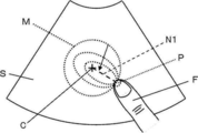
- the shape of the caliper is not particularly limited as long as the position on the display screen of the touch panel 8 can be designated, such as a cruciform and a circle. In FIG. 4, a cruciform caliper C is shown as an example.
- the caliper operation control unit 10 of the processor 22 surrounds the caliper in correspondence with the caliper displayed on the display screen of the touch panel 8 described later, and moves the caliper within the display screen.
- the caliper operation effective area is displayed on the display screen of the touch panel 8 through the display control unit 7.
- the caliper operation effective area is disposed at a constant distance from the caliper.
- FIG. 4 shows a circular caliper operation effective area M surrounded by the caliper C and having a distance to the caliper, that is, a radius L.
- the caliper operation control unit 10 displays a touch confirmation display area, which is smaller than the caliper operation effective area with the user's touch position on the caliper operation effective area as a center, on the display screen of the touch panel 8.
- FIG. 5 shows a circular touch confirmation display area N arranged at the touch position by the finger F of the user.
- the device control unit 11 of the processor 22 controls the respective units of the ultrasound diagnostic device 1 based on the touch operation of the user via the touch panel 8.
- the device control unit 11 controls the caliper operation control unit 10 in response to the user's touch operation via the touch panel 8 to display the caliper operation effective area and the touch confirmation display area on the display screen of the touch panel 8. Display control of the caliper operation effective area and the touch confirmation display area by the device control unit 11 will be described in detail later.
- the display control unit 7 of the processor 22 generates a composite image obtained by combining the ultrasonic image generated by the image generation unit 6, the caliper generated by the caliper generation unit 9, the caliper operation effective area and the touch confirmation display area, The generated composite image is displayed on the display screen of the touch panel 8.
- the touch panel 8 of the ultrasonic diagnostic apparatus 1 has a display screen, displays a composite image, and the user performs a touch operation.
- the display screen is configured of, for example, a display device such as an LCD (Liquid Crystal Display).
- the storage unit 12 of the ultrasonic diagnostic apparatus 1 stores an operation program and the like of the ultrasonic diagnostic apparatus 1, and HDD (Hard Disc Drive: hard disk drive), SSD (Solid State Drive: solid state drive), FD (Flexible Disc: flexible disc: Flexible disk), MO disk (Magneto-Optical disc: Magneto-optical disk), MT (Magnetic Tape: Magnetic tape), RAM (Random Access Memory: Random Access Memory), CD (Compact Disc: Compact Disc), DVD (Digital Versatile) Disc: Recording medium such as digital versatile disc), SD card (Secure Digital card), USB memory (Universal Serial Bus memory), server, or the like can be used.
- HDD Hard Disc Drive: hard disk drive
- SSD Solid State Drive: solid state drive
- FD Flexible Disc
- MO disk Magnetic-Optical disc: Magneto-optical disk
- MT Magnetic Tape: Magnetic tape
- RAM Random Access Memory
- CD Compact Disc
- DVD Digital Versatile
- Disc Recording medium such as digital versatile
- the AD conversion unit 5, the image generation unit 6, the display control unit 7, the caliper generation unit 9, the caliper operation control unit 10 and the device control unit 11 are various in CPU (Central Processing Unit) and CPU.
- the control program for performing the processing of (1) may be configured using a digital circuit.
- the AD converter 5, the image generator 6, the display controller 7, the caliper generator 9, the caliper operation controller 10, and the device controller 11 are partially or totally integrated into one CPU. You can also When the CPU executes a control program, the CPU functions as an image generation unit 6, a display control unit 7, a caliper generation unit 9, a caliper operation control unit 10, and a device control unit 11.
- step S1 the caliper generation unit 9 displays the caliper C on the ultrasonic image S displayed on the display screen of the touch panel 8, as shown in FIG.
- step S 2 the device control unit 11 controls the caliper operation control unit 10 to display a circular caliper operation effective area M having a radius L so as to surround the caliper C displayed in step S 1. Display on
- step S3 the device control unit 11 determines whether the user has touched the displayed caliper operation effective area M, that is, the circumference of the circle of the radius L.
- the apparatus control unit 11 stands by until the user touches the caliper operation effective area M, and when the apparatus control unit 11 determines that the user is touching the caliper operation effective area M, the process proceeds to step S4.
- the user touches the touch position P shown in FIG. 4 for the sake of explanation, but any position on the caliper operation effective area M can be touched as the touch position P.
- step S4 the device control unit 11 controls the caliper operation control unit 10 to interrupt the display of the caliper operation effective area M as shown in FIG. 5, and instead of the caliper operation effective area M, the caliper operation effective is effective.
- a touch confirmation display area N smaller than the area M is displayed at the touch position P.
- a part of the touch confirmation display area N is hidden by the finger F of the user and is displayed so as to be slightly exposed from the tip of the finger F.
- the device control unit 11 determines whether or not the position of the finger F of the user, that is, the touch position P has moved. The device control unit 11 stands by until the touch position P moves, and proceeds to step S6 when it is determined that the touch position P is moving.
- step S6 the device control unit 11 controls the caliper generation unit 9 to move the caliper C so as to follow the movement of the touch position P and controls the caliper operation control unit 10, as shown in FIG.
- the touch confirmation display area N is moved following the movement of the touch position P.
- the caliper C moves in the same direction and distance as the movement direction and movement distance of the touch position P and the touch confirmation display area N while keeping a constant distance L from the touch position P and the touch confirmation display area N Do.
- step S7 the device control unit 11 determines whether or not the touch operation by the user has been released, that is, whether or not the finger F of the user has left the touch position P. If the device control unit 11 determines that the touch operation by the user is not canceled, the process returns to step S5, determines whether the touch position P is moved, and the touch position P is moved. The caliper C and the touch confirmation display area N are moved following the touch position P. Thus, while the finger F of the user is touching the touch position P, the touch confirmation display area N continues to be displayed at the touch position P. In step S7, when the device control unit 11 determines that the touch operation by the user is released, the process proceeds to step S8.
- step S8 the device control unit 11 controls the caliper operation control unit 10 to restore the display of the caliper operation effective area M corresponding to the position of the moved caliper C as shown in FIG. , Erase the display of the touch confirmation display area N. As a result, only the caliper C and the caliper operation effective area M are displayed superimposed on the ultrasonic image S.
- the ultrasonic diagnostic apparatus 1 of the present invention when the user touches the caliper operation effective area M displayed on the display screen of the touch panel 8, the display of the caliper operation effective area M is interrupted, and the user operates the caliper If the touch position P is moved while touching the operation effective area M, the position of the caliper C is moved following the movement of the touch position P. Therefore, a portion that the user wants to visually recognize in the ultrasonic image S is a finger or the like of the user The caliper C can be operated without being hidden, and the operability of the touch operation can be improved. In addition, while the user is touching the caliper operation effective area M, the touch confirmation display area N smaller than the caliper operation effective area M is displayed at the touch position P. Therefore, the user is operating the caliper C Can be confirmed visually.
- the shape thereof is not particularly limited as long as it is disposed so as to surround the caliper.
- the caliper operation effective area M an area of a polygon such as a triangle and a square, an area of an arbitrary closed curve, and an area of a set of a plurality of points arranged on the closed curve can be set.
- the caliper operation effective area M is constituted of a set of a plurality of points, for example, eight points arranged on a closed curve surrounding the caliper C, only each point is set as the caliper operation effective area M. It is also possible to set a closed curve such as a circle passing through each point as the actual caliper operation effective area M.
- the size of the caliper operation effective area M can be preset by the user. As described above, since the user can set the size of the caliper operation effective area M, the user can operate the caliper C in accordance with the preference of the user and the ultrasonic image S. It can be improved.
- the size of the caliper operation effective area M can be changed according to the depth when the ultrasonic image S is captured.
- the depth at which the ultrasound image S is captured is deeper, the size of the tissue in the ultrasound image S is smaller than the size of the entire ultrasound image S. Therefore, when changing the size of the caliper operation effective area M according to the depth of the ultrasonic image S, it is preferable to display smaller as the depth is deeper and to display larger as the depth is shallow.
- the depth at which the ultrasound image S is captured may differ depending on the type of ultrasound probe. For example, the linear ultrasound probe has a shallower depth for imaging the ultrasound image S than the convex and radial ultrasound probes. Therefore, the size of the caliper operation effective area M may be changed according to the type of the ultrasound probe that has captured the ultrasound image S.
- the size of the touch confirmation display area N can be preset by the user. For example, when performing a touch operation, there are cases where a user's finger is used and a stylus pen is used. Generally, since the tip of the stylus pen is often thinner than the tip of the finger, if it is decided to use one of the user's finger and the stylus pen in touch operation, the touch confirmation display area N is The portion may be sized to be hidden by the user's finger or the tip of the stylus and slightly exposed from the user's finger or the tip of the stylus. This makes it easy to visually confirm that the user is moving the touch position P and operating the caliper C.
- the size of the touch confirmation display area N is a predetermined size in advance. May be set.
- the size of the touch confirmation display area N may be set smaller than the area of the portion where the tip of the user's finger or the stylus pen in use contacts the touch panel 8. In this case, the touch confirmation display area N can be hidden from being used by the user's finger or stylus pen and not visually recognized by the user, but substantially can not hide the ultrasound image S.
- the display of the touch confirmation display area N is erased and the display of the caliper operation effective area M is restored.
- the display of the touch confirmation display area N may be erased and the display of the caliper operation effective area M may be restored when a predetermined time has elapsed since the release of the touch operation by the user.
- the size of the touch confirmation display area N is set smaller than the thickness of the user's finger, stylus pen, etc., the user hides the finger, the stylus pen, etc. by canceling the touch operation.
- the positional relationship between the touch confirmation display area N and the caliper operation effective area M can be visually recognized.
- the caliper C can be highlighted.
- highlighting of the caliper C for example, changing the color of the caliper C, blinking display of the caliper C, or the like can be adopted. This allows the user to visually recognize that the caliper C is in the operation state.
- the ultrasonic image S having the caliper C disposed therein is stored in an external memory or the like, only the coordinate information of the caliper C or the caliper C is stored in association with the ultrasonic image S. Is preferably not stored.
- the ultrasound image S and a save button are displayed on the display screen of the touch panel 8, and the user touches the save button.
- S can be stored in an external memory or the like (not shown).
- the caliper operation effective area M is erased by the user touching the save button, and Only the displayed ultrasound image S and caliper C can be stored. In this case, for example, the display of the caliper operation effective area M can be restored by using the completion of the storage of the ultrasonic image S and the caliper C as a trigger.
- the caliper operation is effective.
- the display of the area M is erased and the save button is touched by the user in a state where the caliper operation effective area M is not displayed, only the displayed ultrasonic image S and caliper C are displayed in an external memory not shown. It can be saved. In this case, for example, the display of the caliper operation effective area M can be restored with a trigger that the caliper C is touched by the user.
- the caliper operation effective region M is not stored, and therefore, the caliper C is transmitted only to the ultrasonic image S requiring the caliper C operation.
- the operation effective area M can be displayed on the display screen of the touch panel 8.
- Embodiment 2 In the first embodiment, when the user touches the caliper operation effective area M, the display of the caliper operation effective area M is interrupted and the touch confirmation display area N is displayed. At this time, the display of the caliper operation effective area M is performed. Can be set so as to gradually switch to the display of the touch confirmation display area N instead of being erased instantaneously. For example, as shown in FIG. 8, when the user touches the caliper operation effective area M, the caliper operation effective area M is gradually reduced along the direction A1 toward the touch position P, and the touch confirmation display area N is displayed. Switch.
- the ultrasonic diagnostic apparatus according to the second embodiment has the same configuration as the ultrasonic diagnostic apparatus 1 according to the first embodiment shown in FIG. 1, and the caliper operation effective area M and the touch confirmation The display operation of the display area N is performed by controlling the caliper operation control unit 10 by the device control unit 11 shown in FIG.
- the display of the touch confirmation display area N is set not to be erased instantaneously but to be gradually switched to the display of the caliper operation effective area M.
- the touch confirmation display area N gradually expands along the direction A2 toward the caliper C, and the caliper operation effective area M Switch to display.
- Such display operation is performed by the device control unit 11 controlling the caliper operation control unit 10.
- the display of the caliper operation effective area M and the display of the touch confirmation display area N are gradually switched so that the corresponding caliper is changed to the operation state, and the corresponding caliper is It is easy for the user to visually recognize that the operation state has been released, and the operability of the touch operation can be improved.
- the first embodiment exemplifies an embodiment in which a part of the touch confirmation display area N is hidden by the user's finger F and is displayed so as to be slightly exposed from the tip of the finger F.
- the touch confirmation display area N is not limited to this.
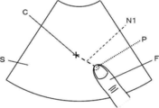
- the touch confirmation display area N1 in the third embodiment is a line connecting the center of the caliper C and the touch position P, and the user touches the touch position P on the caliper operation effective area M.
- the display screen of the touch panel 8 is displayed.
- the touch confirmation display area N1 is moved to the touch position P when the touch position P is moved by moving the finger F as shown in FIG. follow and move.
- the ultrasonic diagnostic apparatus according to the third embodiment has the same structure as the ultrasonic diagnostic apparatus 1 according to the first embodiment shown in FIG. 1, and the caliper operation effective area M and the touch confirmation
- the display operation of the display area N1 is performed by controlling the caliper operation control unit 10 by the device control unit 11 shown in FIG.
- the touch confirmation display area N1 As described above, by displaying the touch confirmation display area N1 as a line connecting the center of the caliper C and the touch position P, it is easy to visually confirm that the user is operating the caliper C. It is possible to improve the operability of the touch operation.
- the display of the caliper operation effective area M When the user touches the caliper operation effective area M, the display of the caliper operation effective area M is instantaneously interrupted and the touch confirmation display area N1 is instantaneously displayed as in the first embodiment.
- the display of the caliper operation effective area M can be set to gradually switch to the display of the touch confirmation display area N1.
- the display of the caliper operation effective area M when the user touches the touch position P on the caliper operation effective area M, the display of the caliper operation effective area M is gradually reduced and the line-shaped touch confirmation display area N1 Switch to the display of.
- the display of the touch confirmation display area N1 changes to a closed curve such as an ellipse, and the outline thereof is gradually enlarged Then, the display switches to the display of the caliper operation effective area M.
- the line-shaped touch confirmation display area N1 in the third embodiment is a solid line displayed transparently and a dotted line that is not a solid line, in order to prevent the ultrasonic image S from being hardly recognized by the user. And a broken line etc. is preferable.
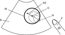
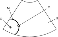
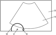
- the user can operate the caliper C by touching an arbitrary position on the caliper operation effective area M, but at this time, the recommended candidate of the touch position on the caliper operation effective area M is selected. It can be shown on the display screen of the touch panel 8. For example, as shown in FIG. 14, when the caliper C is located in the vicinity of the end of the ultrasonic image S and only a part of the caliper operation effective area M is displayed, the displayed caliper operation effective area M And a recommendation point R representing a recommendation candidate of the touch position can be displayed. Further, for example, even when the caliper operation effective area M is all displayed, the recommended point R representing the recommended candidate of the touch position can be displayed by being superimposed on an arbitrary position on the caliper operation effective area M.
- the ultrasonic diagnostic apparatus of the fourth embodiment has the same configuration as the ultrasonic diagnostic apparatus 1 of the first embodiment shown in FIG. Displaying on the screen is performed by the caliper operation control unit 10.
- the user can operate the caliper C by touching an arbitrary portion other than the recommendation point R if it is on the caliper operation effective area M.
- the caliper C is displayed on the ultrasonic image S, but can be displayed on the outside of the ultrasonic image S.
- the caliper C can be displayed outside the ultrasound image S if it is within the display area D of the display screen.
- the display of the caliper operation effective area M is not limited to the ultrasonic image S, and the caliper operation effective area M may be displayed outside the ultrasonic image S within the display area D.
- the caliper operation effective area M since the caliper C is displayed in the vicinity of the end of the display area D, the caliper operation effective area M has an arc shape in which a part is missing. In this manner, even when caliper C is displayed on the outside of ultrasonic image S and at least a part of caliper operation effective area M is displayed on the outside of ultrasonic image S, The recommended point R can be displayed at any place of
- the display area D may be an area across the entire display screen of the touch panel 8 or may be a fixed area defined in the display screen.
- the ultrasound image S is stored in an external memory (not shown) or the like, the entire display area D can be set to be stored.
- the display of the caliper operation effective area M1 corresponding to the caliper C1 is erased and the operation of the caliper C1 can not be performed, and the caliper C2 is supported.
- a caliper operation effective area (not shown) is displayed to enable operation of the caliper C2.
- the two displayed calipers C1 and C2 may be displayed as operable.
- the caliper operation effective area M1 corresponding to one caliper C1 and the caliper operation effective area M2 corresponding to the other caliper C2 can be displayed.
- the present invention can be applied.
- the caliper operation control unit 10 determines the color of the caliper operation effective area, the transparency, the type of the line, and the thickness of the line.
- a plurality of caliper operation effective areas can be displayed so as to be different from each other.
- the color, transparency, type of line, thickness of line, and the like of each caliper operation effective area and the corresponding caliper may be displayed together.
- the display of the caliper operation effective area is instantaneously restored, or for a predetermined time It can be set for each caliper whether or not to return when has passed. For example, when two calipers are displayed on the display screen of the touch panel 8 in order to measure the distance between two points, the user's touch operation is canceled with respect to the caliper operation effective area corresponding to the caliper serving as the start point.
- the display of the caliper operation effective area is instantaneously returned, and the display of the caliper operation effective area is performed when a predetermined time has elapsed after the user's touch operation is canceled with respect to the caliper operation effective area corresponding to the end point caliper. Can be set to return.
- the display of the caliper operation effective area instantaneously returns to the display of the touch confirmation display area, or returns when a predetermined time passes. It can also be set according to the application of the caliper. For example, when two calipers of a start point and an end point are displayed on the display screen of the touch panel 8 in order to measure the distance between two points, the user alternately operates the caliper of the start point and the caliper of the end point finely Often fine-tune the measurements. Therefore, the display of the caliper operation effective area corresponding to each caliper can be set to be restored instantaneously by the release of the touch operation by the user so that the user can operate the caliper smoothly. .
- a measurement line consisting of a closed curve such as a circle or an ellipse is displayed on the display screen of the touch panel 8
- the size and shape of the measurement line may be changed by displaying the calipers of and moving the positions of the plurality of calipers.
- the user operates the caliper while comparing the shape of the tissue in the ultrasonic image, the position of each caliper, and the measurement area such as the area inside the measurement line and the circumference of the measurement line.
- the display of the caliper operation effective area corresponding to each caliper has a certain time elapsed from the release of the touch operation by the user so that the user can easily view the positional relationship between the tissue and the caliper in the ultrasonic image. It can be set to return when.
- the display method of the caliper operation effective region for each caliper as described above may be set in advance, or may be set by the user through the touch panel 8.
- a touch panel having a display screen for displaying the acquired ultrasonic image and performing an input operation by the user;
- a caliper generation processor that generates calipers and displays the calipers on the display screen superimposed on the ultrasound image;
- a caliper operation control processor that encloses the caliper corresponding to the caliper displayed on the display screen and displays a caliper operation effective area for moving the caliper within the display screen on the display screen;
- the caliper operation control processor is controlled to interrupt the display of the caliper operation effective area, and the user touches the caliper operation effective area while touching the touch panel.
- An ultrasonic diagnostic apparatus comprising: a device control processor that controls a processor to return an indication of a caliper operation effective area surrounding a caliper according to a position of a moved caliper.
- Reference Signs List 1 ultrasonic diagnostic apparatus, 2 transducer array, 3 transmitting unit, 4 receiving unit, 5 AD converting unit, 6 image generating unit, 7 display control unit, 8 touch panel, 9 caliper generating unit, 10 caliper operating control unit, 11 apparatus Control unit, 12 storage unit, 13 signal processing unit, 14 DSC, 15 image processing unit, 21 ultrasonic probe, 22 processor, A1, A2 direction, C, C1, C2 caliper, F finger, L radius, M, M1, M2 Caliper operation effective area, N touch confirmation display area, P touch position, R recommended point, S ultrasound image.
Abstract
タッチ操作の操作性を向上させることができる超音波診断装置および超音波診断装置の制御方法を提供する。超音波診断装置(1)は、表示画面を有するタッチパネル(8)と、表示画面にキャリパを表示するキャリパ生成部(9)と、キャリパを囲み且つキャリパを移動操作するためのキャリパ操作有効領域を表示画面に表示するキャリパ操作制御部(10)と、ユーザが表示画面に表示されたキャリパ操作有効領域にタッチするとキャリパ操作制御部(10)を制御してキャリパ操作有効領域の表示を中断し、ユーザがキャリパ操作有効領域にタッチしたままタッチ位置を移動させるとキャリパ生成部(9)を制御してキャリパの位置をタッチ位置の移動に追従させて移動し、ユーザがタッチ操作を解除するとキャリパ操作制御部(10)を制御して移動したキャリパの位置に対応してキャリパを囲むキャリパ操作有効領域の表示を復帰させる装置制御部(11)とを備える。
Description
本発明は、超音波診断装置および超音波診断装置の制御方法に係り、特に、タッチパネルを備えた超音波診断装置および超音波診断装置の制御方法に関する。
近年、タッチパネルを備えた超音波診断装置が普及している。タッチパネルは、一般的に、表示画面を有し、ユーザの指およびスタイラスペン等を表示画面に接触または近接させる、いわゆるタッチ操作により入力操作を受け付ける。そのため、タッチパネルを備えた超音波診断装置によれば、ユーザは、タッチパッド、トラックボールおよびマウス等の入力装置を用いることなく、表示画面に対してタッチ操作を行うことにより表示画面上の位置を指定することができる。このような超音波診断装置においては、タッチ操作の操作性が高いほど超音波診断装置を効率的に使用することができるため、タッチ操作の操作性を向上させる種々の試みがなされている。
例えば、特許文献1には、超音波画像上に表示されたキャリパに対して一定の距離だけ離れた位置に、キャリパに対応付けた操作ボタンを表示させる超音波診断装置が開示されている。表示された操作ボタンがユーザにタッチされたまま移動されると、操作ボタンの移動に追従してキャリパも移動する。そのため、キャリパがユーザの指等に隠れることが防止される。
しかしながら、特許文献1に開示されている超音波診断装置では、操作ボタンが対応するキャリパに対して一定の方向に一定の距離だけ離れた位置のみに配置されているため、ユーザが操作ボタンをタッチしている際に、超音波画像においてユーザが視認したい部分がユーザの指等に隠れてしまう場合があり、結果的に操作性が低下するという問題があった。
本発明は、このような従来の問題点を解消するためになされ、タッチ操作の操作性を向上させることができる超音波診断装置および超音波診断装置の制御方法を提供することを目的とする。
上記目的を達成するために、本発明の超音波診断装置は、取得した超音波画像を表示する表示画面を有し且つユーザにより入力操作を行うためのタッチパネルと、キャリパを生成し且つ超音波画像に重畳して表示画面にキャリパを表示するキャリパ生成部と、表示画面に表示されたキャリパに対応してキャリパを囲み且つ表示画面内においてキャリパを移動操作するためのキャリパ操作有効領域を表示画面に表示するキャリパ操作制御部と、ユーザがタッチパネル上において表示画面に表示されたキャリパ操作有効領域にタッチすると、キャリパ操作制御部を制御してキャリパ操作有効領域の表示を中断し、ユーザがキャリパ操作有効領域にタッチしたままタッチパネル上においてタッチ位置を移動させると、キャリパ生成部を制御して表示画面に表示されているキャリパの位置をタッチ位置の移動に追従させて移動し、ユーザがタッチパネル上におけるタッチ操作を解除すると、キャリパ操作制御部を制御して移動したキャリパの位置に対応してキャリパを囲むキャリパ操作有効領域の表示を復帰させることを特徴とする。
キャリパ操作有効領域は、キャリパを中心とし且つ定められた半径を有する円を描く領域であることが好ましい。
キャリパ操作制御部は、設定されたサイズのキャリパ操作有効領域を表示画面に表示することができる。
キャリパ操作制御部は、設定されたサイズのキャリパ操作有効領域を表示画面に表示することができる。
装置制御部は、ユーザがキャリパ操作有効領域にタッチした場合に、キャリパ操作制御部を制御して、キャリパ操作有効領域の代わりに、タッチ位置を中心とし且つキャリパ操作有効領域よりも小さいタッチ確認表示領域を表示画面に表示させることができる。
さらに、キャリパ操作制御部は、設定されたサイズのタッチ確認表示領域を表示画面に表示することができる。
さらに、キャリパ操作制御部は、設定されたサイズのタッチ確認表示領域を表示画面に表示することができる。
また、装置制御部は、ユーザがキャリパ操作有効領域にタッチした場合に、キャリパ操作制御部を制御して、表示画面に表示されているキャリパ操作有効領域を徐々に縮小してタッチ確認表示領域の表示に切り替えることができる。
また、装置制御部は、ユーザがタッチパネル上におけるタッチ操作を解除した場合に、キャリパ操作制御部を制御して、表示画面に表示されているタッチ確認表示領域を徐々に拡大してキャリパ操作有効領域の表示に切り替えることもできる。
また、装置制御部は、ユーザがタッチパネル上におけるタッチ操作を解除した場合に、キャリパ操作制御部を制御して、表示画面に表示されているタッチ確認表示領域を徐々に拡大してキャリパ操作有効領域の表示に切り替えることもできる。
また、装置制御部は、ユーザがキャリパ操作有効領域にタッチした場合に、キャリパ生成部を制御して表示画面に表示されているキャリパの表示色を変更させる、または、キャリパを点滅表示させることができる。
また、キャリパ操作制御部は、キャリパ操作有効領域内におけるタッチ位置の推奨候補を表す推奨ポイントをキャリパ操作有効領域に重畳して表示画面に表示することができる。
また、キャリパ操作制御部は、キャリパ操作有効領域内におけるタッチ位置の推奨候補を表す推奨ポイントをキャリパ操作有効領域に重畳して表示画面に表示することができる。
本発明の超音波診断装置の制御方法は、表示画面を有し且つユーザにより入力操作を行うためのタッチパネルを備える超音波診断装置の制御方法であって、取得した超音波画像を表示し、キャリパを生成し且つ超音波画像に重畳して表示画面にキャリパを表示し、表示画面に表示されたキャリパに対応してキャリパを囲み且つ表示画面内においてキャリパを移動操作するためのキャリパ操作有効領域を表示画面に表示し、ユーザがタッチパネル上において表示画面に表示されたキャリパ操作有効領域にタッチすると、キャリパ操作有効領域の表示を中断し、ユーザがキャリパ操作有効領域にタッチしたままタッチパネル上においてタッチ位置を移動させると、表示画面に表示されているキャリパの位置をタッチ位置の移動に追従させて移動し、ユーザがタッチパネル上におけるタッチ操作を解除すると、移動したキャリパの位置に対応してキャリパを囲むキャリパ操作有効領域の表示を復帰させる。
本発明によれば、超音波診断装置は、ユーザがタッチパネル上において表示画面に表示されたキャリパ操作有効領域にタッチすると、キャリパ操作制御部を制御してキャリパ操作有効領域の表示を中断し、ユーザがキャリパ操作有効領域にタッチしたままタッチパネル上においてタッチ位置を移動させると、キャリパ生成部を制御して表示画面に表示されているキャリパの位置をタッチ位置の移動に追従させて移動し、ユーザがタッチパネル上におけるタッチ操作を解除すると、キャリパ操作制御部を制御して移動したキャリパの位置に対応してキャリパを囲むキャリパ操作有効領域の表示を復帰させる装置制御部を備えるため、タッチ操作の操作性を向上させることができる。
以下、この発明の実施の形態を添付図面に基づいて説明する。
実施の形態1
図1に、本発明の実施の形態1に係る超音波診断装置1の構成を示す。図1に示すように、超音波診断装置1は、振動子アレイ2を備えており、振動子アレイ2に、それぞれ送信部3および受信部4が接続されている。受信部4には、AD(Analog Digital:アナログデジタル)変換部5、画像生成部6、表示制御部7およびタッチパネル8が順次接続されている。また、表示制御部7に、キャリパ生成部9およびキャリパ操作制御部10がそれぞれ接続されており、キャリパ生成部9は、キャリパ操作制御部10に接続されている。
さらに、送信部3、受信部4、画像生成部6、表示制御部7、タッチパネル8、キャリパ生成部9およびキャリパ操作制御部10に、装置制御部11が接続され、装置制御部11に、格納部12が接続されている。装置制御部11と格納部12とは、互いに、双方向に情報を受け渡し可能に接続されている。
また、振動子アレイ2、送信部3および受信部4により、超音波プローブ21が構成されており、AD変換部5、画像生成部6、表示制御部7、キャリパ生成部9、キャリパ操作制御部10および装置制御部11によりプロセッサ22が構成されている。
図1に示す超音波プローブ21の振動子アレイ2は、1次元または2次元に配列された複数の素子(超音波振動子)を有している。これらの素子は、それぞれ送信部3から供給される駆動信号に従って超音波を送信し、且つ被検体からの反射波を受信して受信信号を出力する。各素子は、例えば、PZT(Lead Zirconate Titanate:チタン酸ジルコン酸鉛)に代表される圧電セラミック、PVDF(Poly Vinylidene Di Fluoride:ポリフッ化ビニリデン)に代表される高分子圧電素子およびPMN-PT(Lead Magnesium Niobate-Lead Titanate:マグネシウムニオブ酸鉛-チタン酸鉛固溶体)に代表される圧電単結晶等からなる圧電体の両端に電極を形成した振動子を用いて構成される。
超音波プローブ21の送信部3は、例えば、複数のパルス発生器を含んでおり、装置制御部11からの制御信号に応じて選択された送信遅延パターンに基づいて、振動子アレイ2の複数の素子から送信される超音波が超音波ビームを形成するようにそれぞれの駆動信号を、遅延量を調節して複数の素子に供給する。このように、振動子アレイ2の素子の電極にパルス状または連続波状の電圧が印加されると、圧電体が伸縮し、それぞれの振動子からパルス状または連続波状の超音波が発生して、それらの超音波の合成波から、超音波ビームが形成される。
送信された超音波ビームは、例えば、被検体の部位等の対象において反射され、超音波プローブ21の振動子アレイ2に向かって伝搬する。このように振動子アレイ2に向かって伝搬する超音波は、振動子アレイ2を構成するそれぞれの素子により受信される。この際に、振動子アレイ2を構成するそれぞれの振動子は、伝搬する超音波を受信することにより伸縮して電気信号を発生させ、それらの電気信号は、超音波の受信信号として、それぞれの振動子から受信部4に出力される。図示しないが、受信部4は、それぞれの振動子から入力された超音波の受信信号を増幅するための増幅部を有しており、ここで増幅された信号がプロセッサ22のAD変換部5においてデジタル化された素子データに変換されると、画像生成部6に出力される。
プロセッサ22の画像生成部6は、図2に示すように、信号処理部13、DSC(Digital Scan Converter:デジタルスキャンコンバータ)14および画像処理部15が直列接続された構成を有している。信号処理部13は、装置制御部11からの制御信号に応じて選択された受信遅延パターンに基づき、設定された音速に従う各素子データにそれぞれの遅延を与えて加算(整相加算)を施す、受信フォーカス処理を行う。この受信フォーカス処理により、超音波エコーの焦点が絞り込まれた音線信号が生成される。また、信号処理部13は、生成された音線信号に対して、超音波が反射した位置の深度に応じて伝搬距離に起因する減衰の補正を施した後、包絡線検波処理を施して、被検体内の組織に関する断層画像情報であるBモード画像信号を生成する。このように生成されたBモード画像信号は、DSC14に出力される。
DSC14は、Bモード画像信号を通常のテレビジョン信号の走査方式に従う画像信号にラスター変換する。画像処理部15は、DSC14において得られた画像データに対して、明るさ補正、階調補正、シャープネス補正および色補正等の各種の必要な画像処理を施した後、Bモード画像信号を表示制御部7に出力する。以下では、このBモード画像信号を超音波画像と呼ぶ。
プロセッサ22のキャリパ生成部9は、キャリパを生成し且つ生成したキャリパを超音波画像に重畳するように、表示制御部7を介して後述するタッチパネル8の表示画面に表示する。ここで、キャリパとは、タッチパネル8の表示画面上の位置を指定するためのカーソルである。キャリパの形状は、十字形および円形等、タッチパネル8の表示画面における位置を指定できれば特に限定されない。図4には、例として十字形のキャリパCが示される。
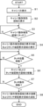
図1に示すように、プロセッサ22のキャリパ操作制御部10は、後述するタッチパネル8の表示画面に表示されたキャリパに対応してキャリパを囲み、且つ、表示画面内においてキャリパを移動操作するためのキャリパ操作有効領域を、表示制御部7を介してタッチパネル8の表示画面に表示する。このキャリパ操作有効領域は、キャリパから一定の距離を隔てて配置される。例えば、図4に、キャリパCを中心として囲み、キャリパとの距離すなわち半径Lを有する円形のキャリパ操作有効領域Mが示される。また、キャリパ操作制御部10は、キャリパ操作有効領域上におけるユーザのタッチ位置を中心とし且つキャリパ操作有効領域よりも小さいタッチ確認表示領域をタッチパネル8の表示画面に表示する。例えば、図5に、ユーザの指Fによるタッチ位置に配置された円形のタッチ確認表示領域Nが示される。
プロセッサ22の装置制御部11は、タッチパネル8を介したユーザのタッチ操作に基づいて、超音波診断装置1の各部の制御を行う。特に、装置制御部11は、タッチパネル8を介したユーザのタッチ操作に応じて、キャリパ操作制御部10を制御し、キャリパ操作有効領域およびタッチ確認表示領域をタッチパネル8の表示画面に表示させる。装置制御部11によるキャリパ操作有効領域およびタッチ確認表示領域の表示制御については、後に詳細に説明する。
プロセッサ22の表示制御部7は、画像生成部6により生成された超音波画像とキャリパ生成部9により生成されたキャリパと、キャリパ操作有効領域およびタッチ確認表示領域を合成した合成画像を生成し、生成した合成画像をタッチパネル8の表示画面に表示させる。
超音波診断装置1のタッチパネル8は、表示画面を有し、合成画像を表示し、且つ、ユーザがタッチ操作を行う。表示画面は、例えば、LCD(Liquid Crystal Display:液晶ディスプレイ)等のディスプレイ装置により構成される。
超音波診断装置1の格納部12は、超音波診断装置1の動作プログラム等を格納し、HDD(Hard Disc Drive:ハードディスクドライブ)、SSD(Solid State Drive:ソリッドステートドライブ)、FD(Flexible Disc:フレキシブルディスク)、MOディスク(Magneto-Optical disc:光磁気ディスク)、MT(Magnetic Tape:磁気テープ)、RAM(Random Access Memory:ランダムアクセスメモリ)、CD(Compact Disc:コンパクトディスク)、DVD(Digital Versatile Disc:デジタルバーサタイルディスク)、SDカード(Secure Digital card:セキュアデジタルカード)、USBメモリ(Universal Serial Bus memory:ユニバーサルシリアルバスメモリ)等の記録メディア、またはサーバ等を用いることができる。
なお、AD変換部5、画像生成部6、表示制御部7、キャリパ生成部9、キャリパ操作制御部10および装置制御部11は、CPU(Central Processing Unit:中央処理装置)、および、CPUに各種の処理を行わせるための制御プログラムから構成されるが、それらを、デジタル回路を用いて構成しても良い。また、これらのAD変換部5、画像生成部6、表示制御部7、キャリパ生成部9、キャリパ操作制御部10および装置制御部11を部分的にあるいは全体的に1つのCPUに統合させて構成することもできる。CPUが制御プログラムを実行することにより、当該CPUが画像生成部6、表示制御部7、キャリパ生成部9、キャリパ操作制御部10および装置制御部11として機能する。
次に、図3に示すフローチャートおよび図4~図7を用いて、本発明の実施の形態1の超音波診断装置1においてキャリパの操作をする際の動作について詳細に説明する。
まず、ステップS1において、キャリパ生成部9は、図4に示すように、タッチパネル8の表示画面に表示された超音波画像Sに重畳してキャリパCを表示する。
続くステップS2において、装置制御部11は、キャリパ操作制御部10を制御して、ステップS1において表示されたキャリパCを囲むように半径Lを有する円形のキャリパ操作有効領域Mをタッチパネル8の表示画面に表示する。
まず、ステップS1において、キャリパ生成部9は、図4に示すように、タッチパネル8の表示画面に表示された超音波画像Sに重畳してキャリパCを表示する。
続くステップS2において、装置制御部11は、キャリパ操作制御部10を制御して、ステップS1において表示されたキャリパCを囲むように半径Lを有する円形のキャリパ操作有効領域Mをタッチパネル8の表示画面に表示する。
ステップS3では、装置制御部11は、表示されたキャリパ操作有効領域Mすなわち半径Lの円の円周上にユーザがタッチしたか否かを判定する。装置制御部11は、キャリパ操作有効領域Mにユーザがタッチするまで待機し、キャリパ操作有効領域Mにユーザがタッチしていると装置制御部11が判定した場合に、ステップS4に進む。なお、以下では説明のため、ユーザは、図4に示すタッチ位置Pにタッチするとするが、キャリパ操作有効領域M上の任意の箇所をタッチ位置Pとしてタッチすることもできる。
ステップS4において、装置制御部11は、キャリパ操作制御部10を制御して、図5に示すように、キャリパ操作有効領域Mの表示を中断し、キャリパ操作有効領域Mの代わりに、キャリパ操作有効領域Mよりも小さいタッチ確認表示領域Nをタッチ位置Pに表示させる。図5において、タッチ確認表示領域Nは、一部がユーザの指Fに隠れており、指Fの先端からわずかに露出するように表示されている。
続くステップS5において、装置制御部11は、ユーザの指Fの位置すなわちタッチ位置Pが移動しているか否かを判定する。装置制御部11は、タッチ位置Pが移動するまで待機し、タッチ位置Pが移動していると判定した場合に、ステップS6に進む。
続くステップS5において、装置制御部11は、ユーザの指Fの位置すなわちタッチ位置Pが移動しているか否かを判定する。装置制御部11は、タッチ位置Pが移動するまで待機し、タッチ位置Pが移動していると判定した場合に、ステップS6に進む。
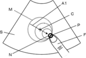
ステップS6において、装置制御部11は、図6に示すように、キャリパ生成部9を制御してキャリパCをタッチ位置Pの移動に追従させて移動させ、且つ、キャリパ操作制御部10を制御してタッチ確認表示領域Nをタッチ位置Pの移動に追従させて移動させる。この際に、キャリパCは、タッチ位置Pおよびタッチ確認表示領域Nと一定の距離Lを保ったまま、タッチ位置Pおよびタッチ確認表示領域Nの移動方向および移動距離と同一の方向および距離を移動する。
続くステップS7において、装置制御部11は、ユーザによるタッチ操作が解除されたか否か、すなわち、ユーザの指Fがタッチ位置Pから離れたか否かを判定する。装置制御部11は、ユーザによるタッチ操作が解除されていないと判定した場合には、ステップS5に戻り、タッチ位置Pが移動しているか否かを判定し、タッチ位置Pが移動している場合に、キャリパCおよびタッチ確認表示領域Nをタッチ位置Pに追従して移動させる。このように、ユーザの指Fがタッチ位置Pにタッチしている間は、タッチ位置Pにタッチ確認表示領域Nが表示され続ける。ステップS7において、ユーザによるタッチ操作が解除されたと装置制御部11が判断した場合に、ステップS8に進む。
ステップS8において、装置制御部11は、キャリパ操作制御部10を制御して、図7に示すように、移動されたキャリパCの位置に対応してキャリパ操作有効領域Mの表示を復帰させ、且つ、タッチ確認表示領域Nの表示を消去する。この結果、キャリパCとキャリパ操作有効領域Mのみが超音波画像Sに重畳して表示される。
以上のように、本発明の超音波診断装置1によれば、ユーザがタッチパネル8の表示画面に表示されたキャリパ操作有効領域Mにタッチするとキャリパ操作有効領域Mの表示が中断され、ユーザがキャリパ操作有効領域Mにタッチしたままタッチ位置Pを移動させるとキャリパCの位置がタッチ位置Pの移動に追従して移動されるため、超音波画像Sにおいてユーザが視認したい部分がユーザの指等に隠れずにキャリパCを操作することができ、タッチ操作の操作性を向上させることができる。
また、ユーザがキャリパ操作有効領域Mにタッチしている間は、タッチ位置Pにおいてキャリパ操作有効領域Mよりも小さいタッチ確認表示領域Nが表示されるため、ユーザがキャリパCを操作していることを視覚的に確認することができる。
また、ユーザがキャリパ操作有効領域Mにタッチしている間は、タッチ位置Pにおいてキャリパ操作有効領域Mよりも小さいタッチ確認表示領域Nが表示されるため、ユーザがキャリパCを操作していることを視覚的に確認することができる。
なお、キャリパ操作有効領域Mとして、円形の領域を例示しているが、キャリパを囲むように配置されていれば、その形状は特に限定されない。例えば、キャリパ操作有効領域Mとして、三角形および四角形等の多角形の領域、任意の閉曲線からなる領域、および、閉曲線上に配列された複数の点の集合からなる領域を設定することができる。特に、キャリパ操作有効領域Mが複数の点の集合、例えば、キャリパCを囲む閉曲線上に配列された8つの点から構成されている場合には、それぞれの点のみをキャリパ操作有効領域Mとして設定することができ、また、それぞれの点を通る円等の表示されない閉曲線を実際のキャリパ操作有効領域Mとして設定することもできる。
また、キャリパ操作有効領域Mの大きさは、ユーザにより予め設定されることができる。このように、ユーザがキャリパ操作有効領域Mの大きさを設定できることにより、ユーザは、ユーザの好みおよび超音波画像Sに合わせたキャリパCの操作をすることができるため、タッチ操作の操作性を向上させることができる。
また、キャリパ操作有効領域Mの大きさは、超音波画像Sが撮像された際の深度に応じて変化させることができる。一般に、超音波画像Sが撮像された際の深度が深いほど、超音波画像S全体の大きさに対して、超音波画像S中の組織の大きさが小さく写る。そのため、キャリパ操作有効領域Mの大きさを、超音波画像Sの深度に応じて変化させる場合には、深度が深いほど小さく表示し、深度が浅いほど大きく表示することが好ましい。また、一般に、超音波画像Sを撮像する際の深度は、超音波プローブの種類に応じて異なることがある。例えば、リニア型の超音波プローブは、コンベックス型およびラジアル型の超音波プローブよりも、超音波画像Sを撮像する際の深度が浅い。そのため、超音波画像Sを撮像した超音波プローブの種類に応じてキャリパ操作有効領域Mの大きさを変化させてもよい。
また、タッチ確認表示領域Nの大きさは、ユーザにより予め設定されることができる。例えば、タッチ操作を行う際に、ユーザの指が使用される場合とスタイラスペンが使用される場合とがある。
一般に、スタイラスペンの先端は、指の先端よりも細いことが多いため、タッチ操作においてユーザの指およびスタイラスペンの一方を使用することが決まっている場合には、タッチ確認表示領域Nは、一部がユーザの指またはスタイラスペンの先端に隠れ、ユーザの指またはスタイラスペンの先端からわずかに露出するような大きさに設定されることができる。これにより、ユーザがタッチ位置Pを移動させてキャリパCを操作していることを視覚的に確認しやすくすることができる。
一般に、スタイラスペンの先端は、指の先端よりも細いことが多いため、タッチ操作においてユーザの指およびスタイラスペンの一方を使用することが決まっている場合には、タッチ確認表示領域Nは、一部がユーザの指またはスタイラスペンの先端に隠れ、ユーザの指またはスタイラスペンの先端からわずかに露出するような大きさに設定されることができる。これにより、ユーザがタッチ位置Pを移動させてキャリパCを操作していることを視覚的に確認しやすくすることができる。
また、ユーザがキャリパ操作有効領域M上のタッチ位置Pをタッチする際にユーザの指またはスタイラスペンのいずれを使用する場合であっても、タッチ確認表示領域Nの大きさは、予め一定の大きさに設定されていてもよい。
また、タッチ確認表示領域Nの大きさは、使用するユーザの指またはスタイラスペンの先端がタッチパネル8に接触する部分の面積よりも小さく設定されていてもよい。この場合に、タッチ確認表示領域Nは、使用するユーザの指またはスタイラスペンに隠れて、ユーザに視認されなくなるが、実質的に超音波画像Sを隠さないようにすることができる。
また、タッチ確認表示領域Nの大きさは、使用するユーザの指またはスタイラスペンの先端がタッチパネル8に接触する部分の面積よりも小さく設定されていてもよい。この場合に、タッチ確認表示領域Nは、使用するユーザの指またはスタイラスペンに隠れて、ユーザに視認されなくなるが、実質的に超音波画像Sを隠さないようにすることができる。
また、実施の形態1では、ユーザがキャリパ操作有効領域Mに対するタッチ操作を解除した際に、タッチ確認表示領域Nの表示が消去され、且つ、キャリパ操作有効領域Mの表示が復帰されるが、ユーザのタッチ操作が解除されてから一定時間が経過した際に、タッチ確認表示領域Nの表示が消去され、キャリパ操作有効領域Mの表示が復帰されることもできる。特に、タッチ確認表示領域Nの大きさが、ユーザの指およびスタイラスペン等の太さよりも小さく設定されている場合に、ユーザが、タッチ操作を解除することにより、指およびスタイラスペン等に隠れていたタッチ確認表示領域Nとキャリパ操作有効領域Mとの位置関係を視認することができる。
また、キャリパ操作有効領域Mがユーザによりタッチされている間に、キャリパCを強調表示することができる。キャリパCの強調表示として、例えば、キャリパCの色を変更すること、キャリパCを点滅表示すること等を採用することができる。これにより、キャリパCが操作状態であることをユーザに視認させることができる。
また、図示しないが、キャリパCを配置した超音波画像Sを外部メモリ等に保存した場合に、キャリパCまたはキャリパCの座標情報のみを超音波画像Sに関連付けて保存し、キャリパ操作有効領域Mは保存しないことが好ましい。
ここで、例えば、超音波画像Sを保存するための操作として、タッチパネル8の表示画面に超音波画像Sおよび図示しない保存ボタンを表示しておき、ユーザが保存ボタンをタッチすることにより超音波画像Sを図示しない外部メモリ等に保存することができる。この際に、超音波画像Sに重畳してキャリパCおよびキャリパ操作有効領域Mが表示されている場合には、例えば、ユーザが保存ボタンをタッチすることによりキャリパ操作有効領域Mが消去され、且つ、表示されている超音波画像SおよびキャリパCのみが保存されることができる。この場合に、例えば、超音波画像SおよびキャリパCの保存が完了することをトリガとして、キャリパ操作有効領域Mの表示を復帰させることができる。
ここで、例えば、超音波画像Sを保存するための操作として、タッチパネル8の表示画面に超音波画像Sおよび図示しない保存ボタンを表示しておき、ユーザが保存ボタンをタッチすることにより超音波画像Sを図示しない外部メモリ等に保存することができる。この際に、超音波画像Sに重畳してキャリパCおよびキャリパ操作有効領域Mが表示されている場合には、例えば、ユーザが保存ボタンをタッチすることによりキャリパ操作有効領域Mが消去され、且つ、表示されている超音波画像SおよびキャリパCのみが保存されることができる。この場合に、例えば、超音波画像SおよびキャリパCの保存が完了することをトリガとして、キャリパ操作有効領域Mの表示を復帰させることができる。
また、例えば、ユーザが定められた時間の間にキャリパ操作有効領域Mまたはキャリパ操作有効領域M上のタッチ位置Pを2回タッチする等、予め決められた操作を行った場合に、キャリパ操作有効領域Mの表示が消去され、キャリパ操作有効領域Mが表示されていない状態においてユーザにより保存ボタンがタッチされることにより、表示されている超音波画像SおよびキャリパCのみが図示しない外部メモリ等に保存されることができる。この場合に、例えば、ユーザによりキャリパCがタッチされることをトリガとして、キャリパ操作有効領域Mの表示を復帰させることができる。
このように、キャリパCを配置した超音波画像Sを外部メモリ等に保存した場合に、キャリパ操作有効領域Mを保存しないことにより、キャリパCの操作が必要な超音波画像Sに対してのみキャリパ操作有効領域Mをタッチパネル8の表示画面に表示することができる。
このように、キャリパCを配置した超音波画像Sを外部メモリ等に保存した場合に、キャリパ操作有効領域Mを保存しないことにより、キャリパCの操作が必要な超音波画像Sに対してのみキャリパ操作有効領域Mをタッチパネル8の表示画面に表示することができる。
実施の形態2
実施の形態1では、ユーザがキャリパ操作有効領域Mをタッチするとキャリパ操作有効領域Mの表示が中断され、且つタッチ確認表示領域Nが表示されるが、この際に、キャリパ操作有効領域Mの表示は、瞬時に消去されるのではなく、徐々にタッチ確認表示領域Nの表示に切り替わるように設定されることもできる。例えば、図8に示すように、ユーザがキャリパ操作有効領域Mをタッチすると、キャリパ操作有効領域Mは、タッチ位置Pに向かう方向A1に沿って徐々に縮小し、タッチ確認表示領域Nの表示に切り替わる。
ここで、図示しないが、実施の形態2の超音波診断装置は、図1に示す実施の形態1の超音波診断装置1と同一の構成を有しており、キャリパ操作有効領域Mおよびタッチ確認表示領域Nの表示動作は、図1に示す装置制御部11が、キャリパ操作制御部10を制御することによりなされる。
同様に、ユーザがタッチパネル8上におけるタッチ操作を解除した際に、タッチ確認表示領域Nの表示は、瞬時に消去されるのではなく、徐々にキャリパ操作有効領域Mの表示に切り替わるように設定されることができる。例えば、図9に示すように、ユーザがキャリパ操作有効領域Mのタッチ操作を解除すると、タッチ確認表示領域Nは、キャリパCに向かう方向A2に沿って徐々に拡大し、キャリパ操作有効領域Mの表示に切り替わる。このような表示動作は、装置制御部11が、キャリパ操作制御部10を制御することによりなされる。
以上のように、キャリパ操作有効領域Mの表示とタッチ確認表示領域Nの表示とが徐々に切り替わるように表示されることにより、対応するキャリパが操作状態に変化したこと、および、対応するキャリパが操作状態から解除されたことをユーザに視認されやすくし、タッチ操作の操作性を向上させることができる。
実施の形態3
実施の形態1では、タッチ確認表示領域Nとして、一部がユーザの指Fに隠れており、指Fの先端からわずかに露出するように表示されている実施の形態を例示しているが、タッチ確認表示領域Nは、これに限定されない。
実施の形態1では、タッチ確認表示領域Nとして、一部がユーザの指Fに隠れており、指Fの先端からわずかに露出するように表示されている実施の形態を例示しているが、タッチ確認表示領域Nは、これに限定されない。
図10に示すように、実施の形態3におけるタッチ確認表示領域N1は、キャリパCの中心とタッチ位置Pとを結ぶ線分であり、ユーザがキャリパ操作有効領域M上のタッチ位置Pにタッチすることによりタッチパネル8の表示画面に表示される。このタッチ確認表示領域N1は、実施の形態1におけるタッチ確認表示領域Nと同様に、図11に示すように、ユーザが指Fを移動させることによりタッチ位置Pを移動させると、タッチ位置Pに追従して移動する。
ここで、図示しないが、実施の形態3の超音波診断装置は、図1に示す実施の形態1の超音波診断装置1と同一の構造を有しており、キャリパ操作有効領域Mおよびタッチ確認表示領域N1の表示動作は、図1に示す装置制御部11が、キャリパ操作制御部10を制御することによりなされる。
ここで、図示しないが、実施の形態3の超音波診断装置は、図1に示す実施の形態1の超音波診断装置1と同一の構造を有しており、キャリパ操作有効領域Mおよびタッチ確認表示領域N1の表示動作は、図1に示す装置制御部11が、キャリパ操作制御部10を制御することによりなされる。
このように、タッチ確認表示領域N1を、キャリパCの中心とタッチ位置Pとを結ぶ線分として表示することにより、ユーザがキャリパCを操作していることを視覚的に確認しやすくすることができ、タッチ操作の操作性を向上させることができる。
なお、ユーザがキャリパ操作有効領域Mをタッチした場合に、実施の形態1と同様に、キャリパ操作有効領域Mの表示が瞬時に中断され、且つ、タッチ確認表示領域N1が瞬時に表示されることができるが、実施の形態2と同様に、キャリパ操作有効領域Mの表示が徐々にタッチ確認表示領域N1の表示に切り替わるように設定されることもできる。
この場合に、例えば図12に示すように、ユーザがキャリパ操作有効領域M上のタッチ位置Pをタッチすると、キャリパ操作有効領域Mの表示が徐々に縮小されて線分状のタッチ確認表示領域N1の表示に切り替わる。また、ユーザが指Fを離してタッチ操作を解除すると、例えば図13に示すように、タッチ確認表示領域N1の表示が楕円等の閉曲線形状に変化し、且つ、その輪郭線が徐々に拡大されてキャリパ操作有効領域Mの表示に切り替わる。
この場合に、例えば図12に示すように、ユーザがキャリパ操作有効領域M上のタッチ位置Pをタッチすると、キャリパ操作有効領域Mの表示が徐々に縮小されて線分状のタッチ確認表示領域N1の表示に切り替わる。また、ユーザが指Fを離してタッチ操作を解除すると、例えば図13に示すように、タッチ確認表示領域N1の表示が楕円等の閉曲線形状に変化し、且つ、その輪郭線が徐々に拡大されてキャリパ操作有効領域Mの表示に切り替わる。
また、実施の形態3における線分状のタッチ確認表示領域N1は、超音波画像Sがユーザに視認されにくくなることを防止するために、透けて表示されている実線、および、実線ではない点線および破線等であることが好ましい。
実施の形態4
本開示では、ユーザは、キャリパ操作有効領域M上の任意の箇所をタッチすることにより、キャリパCを操作することができるが、この際に、キャリパ操作有効領域M上のタッチ位置の推奨候補をタッチパネル8の表示画面において示すことができる。
例えば、図14に示すように、キャリパCが超音波画像Sの端部近傍に位置し、キャリパ操作有効領域Mの一部のみが表示されている場合に、表示されているキャリパ操作有効領域Mに重畳して、タッチ位置の推奨候補を表す推奨ポイントRを表示することができる。
また、例えば、キャリパ操作有効領域Mが全て表示されている場合も、キャリパ操作有効領域M上の任意の箇所に重畳して、タッチ位置の推奨候補を表す推奨ポイントRを表示することができる。
ここで、図示しないが、実施の形態4の超音波診断装置は、図1に示す実施の形態1の超音波診断装置1と同一の構成を有しており、推奨ポイントRをタッチパネル8の表示画面に表示させることは、キャリパ操作制御部10によりなされる。
また、実施の形態4において、ユーザは、キャリパ操作有効領域M上であれば、推奨ポイントR以外の任意の箇所をタッチして、キャリパCを操作することができる。
また、実施の形態4において、ユーザは、キャリパ操作有効領域M上であれば、推奨ポイントR以外の任意の箇所をタッチして、キャリパCを操作することができる。
以上のように、キャリパ操作有効領域M上の推奨ポイントRをタッチパネル8の表示画面に表示させることにより、キャリパ操作有効領域Mを用いたキャリパCの操作に慣れていないユーザであっても、キャリパCの操作を簡単に行うことができる。
なお、図14に示す例では、キャリパCは、超音波画像S上に表示されているが、超音波画像Sの外側に表示されることもできる。例えば、図15に示すように、キャリパCは、表示画面の表示領域D内であれば、超音波画像Sの外側に表示されることができる。この際に、キャリパ操作有効領域Mの表示は超音波画像S上に限られず、表示領域D内であれば、超音波画像Sの外側にキャリパ操作有効領域Mが表示されてもよい。図15に示す例では、キャリパCが表示領域Dの端部近傍に表示されているため、キャリパ操作有効領域Mは、一部が欠けた円弧形状を有している。このように、キャリパCが超音波画像Sの外側に表示され、キャリパ操作有効領域Mの少なくとも一部が超音波画像Sの外側に表示されている場合であっても、キャリパ操作有効領域M上の任意の箇所に推奨ポイントRを表示することができる。
ここで、表示領域Dとは、タッチパネル8の表示画面全体に亘る領域でもよく、表示画面内に定められた一定の領域でもよい。また、超音波画像Sが図示しない外部メモリ等に保存される際に、表示領域D全体が保存されるように設定されることができる。
実施の形態5
実施の形態1~4では、タッチパネル8の表示画面に1つのキャリパCを表示する例を示しているが、複数のキャリパが同時に表示されていてもよい。
例えば、超音波画像上の2点間の距離を計測する場合に、超音波画像に重畳して2つのキャリパを表示することができる。この場合に、例えば、図16に示すように、表示された2つのキャリパのうち一方のキャリパC1のみを操作可能なキャリパとし、このキャリパC1のみに対応したキャリパ操作有効領域M1をタッチパネル8の表示画面に表示させることができる。キャリパC1の操作が終了し、キャリパC2の操作を行う際には、キャリパC1に対応したキャリパ操作有効領域M1の表示が消去されてキャリパC1の操作ができない状態になり、且つ、キャリパC2に対応する図示しないキャリパ操作有効領域が表示されてキャリパC2が操作可能になる。
また、例えば、図17に示すように、表示された2つのキャリパC1およびC2がいずれも操作可能な状態として表示されることもできる。この場合には、一方のキャリパC1に対応するキャリパ操作有効領域M1と、他方のキャリパC2に対応するキャリパ操作有効領域M2が表示されることができる。
以上のように、タッチパネル8の表示画面に複数のキャリパが表示されている場合であっても、本発明を適用することができる。
なお、操作可能な状態の複数のキャリパ操作有効領域がタッチパネル8の表示画面に表示されている場合に、キャリパ操作制御部10は、キャリパ操作有効領域の色、透明度、線の種類および線の太さ等が、それぞれ、異なるように、複数のキャリパ操作有効領域を表示することができる。この際に、それぞれのキャリパ操作有効領域と対応するキャリパとの色、透明度、線の種類および線の太さ等を合わせて表示してもよい。これにより、複数のキャリパに対応するキャリパ操作有効領域がタッチパネル8の表示画面に表示されていても、それぞれのキャリパおよびキャリパ操作有効領域がユーザに視認されやすくすることができる。
また、操作可能な状態の複数のキャリパ操作有効領域がタッチパネル8の表示画面に表示されている場合に、ユーザにより操作されていないキャリパおよび対応するキャリパ操作有効領域の透明度のみを大きくすることができる。これにより、ユーザに操作されているキャリパのみを強調してタッチパネル8の表示画面に表示することができる。
また、タッチパネル8の表示画面に複数のキャリパが表示されている場合に、キャリパ操作有効領域に対するユーザのタッチ操作が解除されたときに、キャリパ操作有効領域の表示が瞬時に復帰するか、一定時間が経過した際に復帰するかをそれぞれのキャリパ毎に設定することができる。例えば、2点間の距離を計測するために、タッチパネル8の表示画面に2つのキャリパが表示された場合に、始点となるキャリパに対応するキャリパ操作有効領域に対し、ユーザのタッチ操作が解除された際にキャリパ操作有効領域の表示が瞬時に復帰し、終点となるキャリパに対応するキャリパ操作有効領域に対し、ユーザのタッチ操作が解除されて一定時間が経過した際にキャリパ操作有効領域の表示が復帰するように設定することができる。
また、例えば、キャリパ操作有効領域に対するユーザのタッチ操作が解除された際に、キャリパ操作有効領域の表示がタッチ確認表示領域の表示に瞬時に復帰するか、または、一定時間が経過した際に復帰するかをキャリパの用途に応じて設定することもできる。例えば、2点間の距離を計測するためにタッチパネル8の表示画面に始点および終点の2つのキャリパが表示されている場合には、ユーザが始点のキャリパおよび終点のキャリパを交互に細かく操作しながら計測値を微調整することが多い。そのため、ユーザがキャリパの操作を円滑に行うことができるように、それぞれのキャリパに対応するキャリパ操作有効領域の表示が、ユーザによるタッチ操作の解除により瞬時に復帰するように設定されることができる。
また、例えば、超音波画像に含まれる組織の面積および周長を計測するために、円形および楕円形等の閉曲線からなる計測線をタッチパネル8の表示画面に表示し、計測線の周上に複数のキャリパを表示し、これらの複数のキャリパの位置を移動することにより計測線の大きさおよび形状を変化させることがある。この場合には、ユーザが超音波画像中の組織の形状と、それぞれのキャリパの位置と、計測線の内側の面積および計測線の周長等の計測値とを比較しながらキャリパを操作することが多い。そのため、ユーザが超音波画像中の組織とキャリパとの位置関係等を視認しやすいように、それぞれのキャリパに対応するキャリパ操作有効領域の表示が、ユーザによるタッチ操作の解除から一定時間が経過した際に復帰するように設定されることができる。
なお、以上のような、キャリパ毎のキャリパ操作有効領域の表示方法は、予め設定されていてもよく、タッチパネル8を介してユーザにより設定されることもできる。
なお、以上のような、キャリパ毎のキャリパ操作有効領域の表示方法は、予め設定されていてもよく、タッチパネル8を介してユーザにより設定されることもできる。
上記記載から、以下の付記項1に記載の超音波診断装置を把握することができる。
[付記項1]
取得した超音波画像を表示する表示画面を有し且つユーザにより入力操作を行うためのタッチパネルと、
キャリパを生成し且つ超音波画像に重畳して表示画面にキャリパを表示するキャリパ生成プロセッサと、
表示画面に表示されたキャリパに対応してキャリパを囲み且つ表示画面内においてキャリパを移動操作するためのキャリパ操作有効領域を表示画面に表示するキャリパ操作制御プロセッサと、
ユーザがタッチパネル上において表示画面に表示されたキャリパ操作有効領域にタッチすると、キャリパ操作制御プロセッサを制御してキャリパ操作有効領域の表示を中断し、ユーザがキャリパ操作有効領域にタッチしたままタッチパネル上においてタッチ位置を移動させると、キャリパ生成プロセッサを制御して表示画面に表示されているキャリパの位置をタッチ位置の移動に追従させて移動し、ユーザがタッチパネル上におけるタッチ操作を解除すると、キャリパ操作制御プロセッサを制御して移動したキャリパの位置に対応してキャリパを囲むキャリパ操作有効領域の表示を復帰させる装置制御プロセッサと
を備えた超音波診断装置。
1 超音波診断装置、2 振動子アレイ、3 送信部、4 受信部、5 AD変換部、6 画像生成部、7 表示制御部、8 タッチパネル、9 キャリパ生成部、10 キャリパ操作制御部、11 装置制御部、12 格納部、13 信号処理部、14 DSC、15 画像処理部、21 超音波プローブ、22 プロセッサ、A1,A2 方向、C,C1,C2 キャリパ、F 指、L 半径、M,M1,M2 キャリパ操作有効領域、N タッチ確認表示領域、P タッチ位置、R 推奨ポイント、S 超音波画像。
Claims (10)
- 取得した超音波画像を表示する表示画面を有し且つユーザにより入力操作を行うためのタッチパネルと、
キャリパを生成し且つ前記超音波画像に重畳して前記表示画面に前記キャリパを表示するキャリパ生成部と、
前記表示画面に表示された前記キャリパに対応して前記キャリパを囲み且つ前記表示画面内において前記キャリパを移動操作するためのキャリパ操作有効領域を前記表示画面に表示するキャリパ操作制御部と、
前記ユーザが前記タッチパネル上において前記表示画面に表示された前記キャリパ操作有効領域にタッチすると、前記キャリパ操作制御部を制御して前記キャリパ操作有効領域の表示を中断し、前記ユーザが前記キャリパ操作有効領域にタッチしたまま前記タッチパネル上においてタッチ位置を移動させると、前記キャリパ生成部を制御して前記表示画面に表示されている前記キャリパの位置を前記タッチ位置の移動に追従させて移動し、前記ユーザが前記タッチパネル上におけるタッチ操作を解除すると、前記キャリパ操作制御部を制御して移動した前記キャリパの位置に対応して前記キャリパを囲む前記キャリパ操作有効領域の表示を復帰させる装置制御部と
を備えた超音波診断装置。 - 前記キャリパ操作有効領域は、前記キャリパを中心とし且つ定められた半径を有する円を描く領域である請求項1に記載の超音波診断装置。
- 前記キャリパ操作制御部は、設定されたサイズの前記キャリパ操作有効領域を前記表示画面に表示する請求項1または2に記載の超音波診断装置。
- 前記装置制御部は、前記ユーザが前記キャリパ操作有効領域にタッチした場合に、前記キャリパ操作制御部を制御して、前記キャリパ操作有効領域の代わりに、前記タッチ位置を中心とし且つ前記キャリパ操作有効領域よりも小さいタッチ確認表示領域を前記表示画面に表示させる請求項1~3のいずれか一項に記載の超音波診断装置。
- 前記キャリパ操作制御部は、設定されたサイズの前記タッチ確認表示領域を前記表示画面に表示する請求項4に記載に超音波診断装置。
- 前記装置制御部は、前記ユーザが前記キャリパ操作有効領域にタッチした場合に、前記キャリパ操作制御部を制御して、前記表示画面に表示されている前記キャリパ操作有効領域を徐々に縮小して前記タッチ確認表示領域の表示に切り替える請求項4または5に記載の超音波診断装置。
- 前記装置制御部は、前記ユーザが前記タッチパネル上におけるタッチ操作を解除した場合に、前記キャリパ操作制御部を制御して、前記表示画面に表示されている前記タッチ確認表示領域を徐々に拡大して前記キャリパ操作有効領域の表示に切り替える請求項4~6のいずれか一項に記載の超音波診断装置。
- 前記装置制御部は、前記ユーザが前記キャリパ操作有効領域にタッチした場合に、前記キャリパ生成部を制御して前記表示画面に表示されている前記キャリパの表示色を変更させる、または、前記キャリパを点滅表示させる請求項1~7のいずれか一項に記載の超音波診断装置。
- 前記キャリパ操作制御部は、前記キャリパ操作有効領域内における前記タッチ位置の推奨候補を表す推奨ポイントを前記キャリパ操作有効領域に重畳して前記表示画面に表示する請求項1~8のいずれか一項に記載の超音波診断装置。
- 表示画面を有し且つユーザにより入力操作を行うためのタッチパネルを備える超音波診断装置の制御方法であって、
取得した超音波画像を表示し、
キャリパを生成し且つ前記超音波画像に重畳して前記表示画面に前記キャリパを表示し、
前記表示画面に表示された前記キャリパに対応して前記キャリパを囲み且つ前記表示画面内において前記キャリパを移動操作するためのキャリパ操作有効領域を前記表示画面に表示し、
前記ユーザが前記タッチパネル上において前記表示画面に表示された前記キャリパ操作有効領域にタッチすると、前記キャリパ操作有効領域の表示を中断し、
前記ユーザが前記キャリパ操作有効領域にタッチしたまま前記タッチパネル上においてタッチ位置を移動させると、前記表示画面に表示されている前記キャリパの位置を前記タッチ位置の移動に追従させて移動し、
前記ユーザが前記タッチパネル上におけるタッチ操作を解除すると、移動した前記キャリパの位置に対応して前記キャリパを囲む前記キャリパ操作有効領域の表示を復帰させる超音波診断装置の制御方法。
Priority Applications (4)
| Application Number | Priority Date | Filing Date | Title |
|---|---|---|---|
| CN201880058943.6A CN111065339B (zh) | 2017-09-14 | 2018-06-01 | 超声波诊断装置及超声波诊断装置的控制方法 |
| EP18856481.9A EP3682812B1 (en) | 2017-09-14 | 2018-06-01 | Ultrasonic diagnosis device and control method of ultrasonic diagnosis device |
| JP2019541646A JP6792085B2 (ja) | 2017-09-14 | 2018-06-01 | 超音波診断装置および超音波診断装置の制御方法 |
| US16/804,204 US11036376B2 (en) | 2017-09-14 | 2020-02-28 | Ultrasound diagnosis apparatus and method of controlling ultrasound diagnosis apparatus |
Applications Claiming Priority (2)
| Application Number | Priority Date | Filing Date | Title |
|---|---|---|---|
| JP2017-176977 | 2017-09-14 | ||
| JP2017176977 | 2017-09-14 |
Related Child Applications (1)
| Application Number | Title | Priority Date | Filing Date |
|---|---|---|---|
| US16/804,204 Continuation US11036376B2 (en) | 2017-09-14 | 2020-02-28 | Ultrasound diagnosis apparatus and method of controlling ultrasound diagnosis apparatus |
Publications (1)
| Publication Number | Publication Date |
|---|---|
| WO2019053960A1 true WO2019053960A1 (ja) | 2019-03-21 |
Family
ID=65723259
Family Applications (1)
| Application Number | Title | Priority Date | Filing Date |
|---|---|---|---|
| PCT/JP2018/021166 WO2019053960A1 (ja) | 2017-09-14 | 2018-06-01 | 超音波診断装置および超音波診断装置の制御方法 |
Country Status (5)
| Country | Link |
|---|---|
| US (1) | US11036376B2 (ja) |
| EP (1) | EP3682812B1 (ja) |
| JP (1) | JP6792085B2 (ja) |
| CN (1) | CN111065339B (ja) |
| WO (1) | WO2019053960A1 (ja) |
Cited By (2)
| Publication number | Priority date | Publication date | Assignee | Title |
|---|---|---|---|---|
| CN111513757A (zh) * | 2020-04-23 | 2020-08-11 | 无锡祥生医疗科技股份有限公司 | 测量方法、装置与存储介质 |
| JP2021097837A (ja) * | 2019-12-20 | 2021-07-01 | コニカミノルタ株式会社 | 操作対象切り替え装置、操作対象切り替え方法および操作対象切り替えプログラム |
Citations (5)
| Publication number | Priority date | Publication date | Assignee | Title |
|---|---|---|---|---|
| JP2006179006A (ja) * | 2004-12-22 | 2006-07-06 | Microsoft Corp | カーソルを用いて入力を制御する入力制御方法 |
| JP2010142563A (ja) * | 2008-12-22 | 2010-07-01 | Panasonic Corp | 超音波診断装置 |
| JP2012019824A (ja) | 2010-07-12 | 2012-02-02 | Hitachi Aloka Medical Ltd | 超音波診断装置 |
| JP2016516465A (ja) * | 2013-03-13 | 2016-06-09 | サムスン エレクトロニクス カンパニー リミテッド | コピー映像提供方法、及びそのための超音波装置 |
| JP2018110751A (ja) * | 2017-01-13 | 2018-07-19 | コニカミノルタ株式会社 | 医用画像表示装置 |
Family Cites Families (15)
| Publication number | Priority date | Publication date | Assignee | Title |
|---|---|---|---|---|
| US20060174065A1 (en) * | 2003-06-10 | 2006-08-03 | Kuzara David J | System and method for annotating an ultrasound image |
| US20090131793A1 (en) * | 2007-11-15 | 2009-05-21 | General Electric Company | Portable imaging system having a single screen touch panel |
| CN202113090U (zh) * | 2011-06-10 | 2012-01-18 | 无锡祥生医学影像有限责任公司 | 一种触摸屏超声诊断仪 |
| US20130324850A1 (en) * | 2012-05-31 | 2013-12-05 | Mindray Ds Usa, Inc. | Systems and methods for interfacing with an ultrasound system |
| JP6013051B2 (ja) * | 2012-07-02 | 2016-10-25 | 東芝メディカルシステムズ株式会社 | 超音波診断装置及びその操作支援方法 |
| WO2014142468A1 (en) * | 2013-03-13 | 2014-09-18 | Samsung Electronics Co., Ltd. | Method of providing copy image and ultrasound apparatus therefor |
| JP6364901B2 (ja) * | 2014-04-09 | 2018-08-01 | コニカミノルタ株式会社 | 超音波画像診断装置 |
| CN107977148A (zh) * | 2014-10-11 | 2018-05-01 | 广东欧珀移动通信有限公司 | 移动光标的方法及装置 |
| US10420533B2 (en) * | 2014-11-04 | 2019-09-24 | Samsung Electronics Co., Ltd. | Ultrasound diagnosis apparatus and control method thereof |
| KR102293915B1 (ko) * | 2014-12-05 | 2021-08-26 | 삼성메디슨 주식회사 | 초음파 이미지 처리 방법 및 이를 위한 초음파 장치 |
| US20170090571A1 (en) * | 2015-09-29 | 2017-03-30 | General Electric Company | System and method for displaying and interacting with ultrasound images via a touchscreen |
| KR102532287B1 (ko) * | 2015-10-08 | 2023-05-15 | 삼성메디슨 주식회사 | 초음파 장치 및 그 제어방법 |
| JP6509374B2 (ja) * | 2015-12-17 | 2019-05-08 | オリンパス株式会社 | 超音波観測装置、処理装置、超音波観測装置の作動方法および超音波観測装置の作動プログラム |
| US20170209125A1 (en) * | 2016-01-22 | 2017-07-27 | General Electric Company | Diagnostic system and method for obtaining measurements from a medical image |
| JP6915387B2 (ja) * | 2017-06-02 | 2021-08-04 | コニカミノルタ株式会社 | 医用画像表示装置、タッチ操作制御プログラム及びタッチ操作制御方法 |
-
2018
- 2018-06-01 EP EP18856481.9A patent/EP3682812B1/en active Active
- 2018-06-01 CN CN201880058943.6A patent/CN111065339B/zh active Active
- 2018-06-01 JP JP2019541646A patent/JP6792085B2/ja active Active
- 2018-06-01 WO PCT/JP2018/021166 patent/WO2019053960A1/ja unknown
-
2020
- 2020-02-28 US US16/804,204 patent/US11036376B2/en active Active
Patent Citations (5)
| Publication number | Priority date | Publication date | Assignee | Title |
|---|---|---|---|---|
| JP2006179006A (ja) * | 2004-12-22 | 2006-07-06 | Microsoft Corp | カーソルを用いて入力を制御する入力制御方法 |
| JP2010142563A (ja) * | 2008-12-22 | 2010-07-01 | Panasonic Corp | 超音波診断装置 |
| JP2012019824A (ja) | 2010-07-12 | 2012-02-02 | Hitachi Aloka Medical Ltd | 超音波診断装置 |
| JP2016516465A (ja) * | 2013-03-13 | 2016-06-09 | サムスン エレクトロニクス カンパニー リミテッド | コピー映像提供方法、及びそのための超音波装置 |
| JP2018110751A (ja) * | 2017-01-13 | 2018-07-19 | コニカミノルタ株式会社 | 医用画像表示装置 |
Non-Patent Citations (1)
| Title |
|---|
| See also references of EP3682812A4 |
Cited By (3)
| Publication number | Priority date | Publication date | Assignee | Title |
|---|---|---|---|---|
| JP2021097837A (ja) * | 2019-12-20 | 2021-07-01 | コニカミノルタ株式会社 | 操作対象切り替え装置、操作対象切り替え方法および操作対象切り替えプログラム |
| JP7409070B2 (ja) | 2019-12-20 | 2024-01-09 | コニカミノルタ株式会社 | 操作対象切り替え装置、操作対象切り替え方法および操作対象切り替えプログラム |
| CN111513757A (zh) * | 2020-04-23 | 2020-08-11 | 无锡祥生医疗科技股份有限公司 | 测量方法、装置与存储介质 |
Also Published As
| Publication number | Publication date |
|---|---|
| EP3682812A4 (en) | 2020-11-04 |
| CN111065339B (zh) | 2022-10-18 |
| EP3682812A1 (en) | 2020-07-22 |
| CN111065339A (zh) | 2020-04-24 |
| JPWO2019053960A1 (ja) | 2020-10-01 |
| JP6792085B2 (ja) | 2020-11-25 |
| US11036376B2 (en) | 2021-06-15 |
| US20200201523A1 (en) | 2020-06-25 |
| EP3682812B1 (en) | 2021-03-10 |
Similar Documents
| Publication | Publication Date | Title |
|---|---|---|
| JP5465203B2 (ja) | 超音波診断装置および超音波画像生成方法 | |
| JP6364901B2 (ja) | 超音波画像診断装置 | |
| CN113229846B (zh) | 超声成像方法与设备 | |
| JP4879623B2 (ja) | 超音波診断装置 | |
| US11036376B2 (en) | Ultrasound diagnosis apparatus and method of controlling ultrasound diagnosis apparatus | |
| US20230240655A1 (en) | Ultrasound diagnostic apparatus and display method of ultrasound diagnostic apparatus | |
| JP2018047080A (ja) | 超音波診断装置及びプログラム | |
| US20210030399A1 (en) | Ultrasound system and method for controlling ultrasound system | |
| US20210038194A1 (en) | Ultrasound diagnostic apparatus and method for controlling ultrasound diagnostic apparatus | |
| JP7027081B2 (ja) | 超音波診断装置及びプログラム | |
| US20230240654A1 (en) | Ultrasound diagnostic apparatus and display method of ultrasound diagnostic apparatus | |
| EP4309588A1 (en) | Ultrasonic diagnosis device and method for controlling ultrasonic diagnosis device | |
| US20240081783A1 (en) | Ultrasound diagnostic apparatus and control method of ultrasound diagnostic apparatus | |
| US20240050067A1 (en) | Ultrasonic probe and ultrasonic diagnostic apparatus | |
| JP5972722B2 (ja) | 超音波診断装置および制御プログラム | |
| WO2022168521A1 (ja) | 超音波診断装置および超音波診断装置の制御方法 | |
| JP7040071B2 (ja) | 医用画像表示装置及び非接触入力方法 | |
| JP6733339B2 (ja) | 超音波画像診断装置 | |
| JP2024024441A (ja) | 超音波プローブ及び超音波診断装置 | |
| JP2022171166A (ja) | 医用画像生成装置、医用画像生成方法、およびプログラム | |
| JP5450488B2 (ja) | 超音波診断装置および超音波画像生成方法 | |
| JP2019122642A (ja) | 超音波診断装置及びプログラム | |
| JP2004194962A (ja) | 超音波撮影装置 |
Legal Events
| Date | Code | Title | Description |
|---|---|---|---|
| 121 | Ep: the epo has been informed by wipo that ep was designated in this application |
Ref document number: 18856481 Country of ref document: EP Kind code of ref document: A1 |
|
| ENP | Entry into the national phase |
Ref document number: 2019541646 Country of ref document: JP Kind code of ref document: A |
|
| NENP | Non-entry into the national phase |
Ref country code: DE |
|
| ENP | Entry into the national phase |
Ref document number: 2018856481 Country of ref document: EP Effective date: 20200414 |