WO2019049669A1 - 生産監視システム及び生産監視方法 - Google Patents
生産監視システム及び生産監視方法 Download PDFInfo
- Publication number
- WO2019049669A1 WO2019049669A1 PCT/JP2018/031038 JP2018031038W WO2019049669A1 WO 2019049669 A1 WO2019049669 A1 WO 2019049669A1 JP 2018031038 W JP2018031038 W JP 2018031038W WO 2019049669 A1 WO2019049669 A1 WO 2019049669A1
- Authority
- WO
- WIPO (PCT)
- Prior art keywords
- monitoring data
- data
- monitoring
- threshold
- product
- Prior art date
- Legal status (The legal status is an assumption and is not a legal conclusion. Google has not performed a legal analysis and makes no representation as to the accuracy of the status listed.)
- Ceased
Links
Images


Classifications
-
- G—PHYSICS
- G05—CONTROLLING; REGULATING
- G05B—CONTROL OR REGULATING SYSTEMS IN GENERAL; FUNCTIONAL ELEMENTS OF SUCH SYSTEMS; MONITORING OR TESTING ARRANGEMENTS FOR SUCH SYSTEMS OR ELEMENTS
- G05B19/00—Program-control systems
- G05B19/02—Program-control systems electric
- G05B19/418—Total factory control, i.e. centrally controlling a plurality of machines, e.g. direct or distributed numerical control [DNC], flexible manufacturing systems [FMS], integrated manufacturing systems [IMS] or computer integrated manufacturing [CIM]
-
- G—PHYSICS
- G06—COMPUTING OR CALCULATING; COUNTING
- G06Q—INFORMATION AND COMMUNICATION TECHNOLOGY [ICT] SPECIALLY ADAPTED FOR ADMINISTRATIVE, COMMERCIAL, FINANCIAL, MANAGERIAL OR SUPERVISORY PURPOSES; SYSTEMS OR METHODS SPECIALLY ADAPTED FOR ADMINISTRATIVE, COMMERCIAL, FINANCIAL, MANAGERIAL OR SUPERVISORY PURPOSES, NOT OTHERWISE PROVIDED FOR
- G06Q50/00—Information and communication technology [ICT] specially adapted for implementation of business processes of specific business sectors, e.g. utilities or tourism
- G06Q50/04—Manufacturing
-
- Y—GENERAL TAGGING OF NEW TECHNOLOGICAL DEVELOPMENTS; GENERAL TAGGING OF CROSS-SECTIONAL TECHNOLOGIES SPANNING OVER SEVERAL SECTIONS OF THE IPC; TECHNICAL SUBJECTS COVERED BY FORMER USPC CROSS-REFERENCE ART COLLECTIONS [XRACs] AND DIGESTS
- Y02—TECHNOLOGIES OR APPLICATIONS FOR MITIGATION OR ADAPTATION AGAINST CLIMATE CHANGE
- Y02P—CLIMATE CHANGE MITIGATION TECHNOLOGIES IN THE PRODUCTION OR PROCESSING OF GOODS
- Y02P90/00—Enabling technologies with a potential contribution to greenhouse gas [GHG] emissions mitigation
- Y02P90/02—Total factory control, e.g. smart factories, flexible manufacturing systems [FMS] or integrated manufacturing systems [IMS]
-
- Y—GENERAL TAGGING OF NEW TECHNOLOGICAL DEVELOPMENTS; GENERAL TAGGING OF CROSS-SECTIONAL TECHNOLOGIES SPANNING OVER SEVERAL SECTIONS OF THE IPC; TECHNICAL SUBJECTS COVERED BY FORMER USPC CROSS-REFERENCE ART COLLECTIONS [XRACs] AND DIGESTS
- Y02—TECHNOLOGIES OR APPLICATIONS FOR MITIGATION OR ADAPTATION AGAINST CLIMATE CHANGE
- Y02P—CLIMATE CHANGE MITIGATION TECHNOLOGIES IN THE PRODUCTION OR PROCESSING OF GOODS
- Y02P90/00—Enabling technologies with a potential contribution to greenhouse gas [GHG] emissions mitigation
- Y02P90/30—Computing systems specially adapted for manufacturing
Definitions
- the present invention relates to a production monitoring system and a production monitoring method for monitoring production by a processing machine such as a molding machine, a cutting machine, or a press machine.
- Patent Document 1 discloses a technology for collecting data on quality characteristics in the manufacturing process, extracting data to be detected from the data, monitoring the occurrence of abnormal tendency from these data, and further determining the severity thereof. It is disclosed.
- Patent Document 1 With the technology described in Patent Document 1, the occurrence of abnormal tendency and its severity can be known, but since data on quality characteristics are collected in time units (eg, paragraph 0018), defective products are the next process May flow to
- the object of the present invention is to provide a production monitoring system which can reliably prevent a defective product from flowing to the next process, can investigate the defect cause of the defective product, and can predict and prevent the occurrence of defects. And provide a production monitoring method.
- a production monitoring system includes a data acquisition unit that acquires multiple types of monitoring data from a processing machine for each product processed by the processing machine, and the monitoring data.
- An evaluation unit that evaluates the acquired monitoring data for each product based on the threshold value of the item; and sorting the product processed by the processing machine based on an evaluation result for each product by the evaluation unit.
- the product sorting unit and the product sorting unit sort the product corresponding to the monitoring data which is out of the range of the threshold from other products, a predetermined notification is performed and the range is out of the range of the threshold
- a computer system that characterizes and displays the monitored data.
- each monitoring data of the processing machine is evaluated based on each threshold value of plural types of monitoring data, and processing is performed by the processing machine based on the evaluation result for each product. Since the sorted products are separated, defective products can be reliably prevented from flowing to the next process. Further, when the product sorting unit sorts the product corresponding to the monitoring data which is out of the range of the threshold value from the other products, the computer system performs a predetermined notification and is out of the range of the threshold value. Since the supervised monitoring data is characterized and displayed, the operator can confirm the product regarded as a defective product and can surely grasp the supervised data which is out of the range of the threshold value. Therefore, the cause of the defect of the defective product can be determined from the classified defective products and the monitoring data which is out of the range of the threshold value. Furthermore, the occurrence of defects can be predicted and prevented from the evaluation results by the evaluation unit.
- the product sorting unit determines that at least one of the plurality of types of monitoring data is out of a threshold range of the monitoring data
- the product sorting unit Separate the product corresponding to the monitoring data that is out of the range from the other products. This makes it possible to more reliably prevent defective products from flowing to the next step.
- the production monitoring system further includes a storage unit storing a threshold of the monitoring data, and a storage unit storing the monitoring data when the monitoring data is out of the range of the threshold. And means for changing the threshold value.
- the threshold value can be set to a more appropriate value, and defective products can be more reliably prevented from flowing to the next step.
- a production monitoring method acquires multiple types of monitoring data from a processing machine for each product processed by the processing machine, and the acquired monitoring data is the threshold of each of the monitoring data. It is determined for each one product whether it is within the range of values, and separation data for separating the product processed by the processing machine is generated based on the determination result for each one product, and the range of the threshold value
- separation data is generated which separates the product corresponding to the monitoring data that has become out of the other products
- a predetermined notification is typically performed in a computer system that collects production information from the processing machine, and The monitoring data out of the threshold range is characterized and displayed.
- the classification data is out of the range of the threshold of the monitoring data. It is data for separating the product corresponding to the monitoring data which became The method further sorts the product processed by the processor based on the sorting data. This makes it possible to more reliably prevent defective products from flowing to the next step.
- the threshold value can be set to a more appropriate value, and defective products can be more reliably prevented from flowing to the next step.
- the production monitoring program includes the steps of acquiring, from each processing machine, plural types of monitoring data for each product processed by the processing machine, and the acquired monitoring data corresponds to the monitoring data. Determining, for each product, whether it is within a threshold range, generating separation data for separating a product processed by the processing machine based on the determination result, and the threshold When sorting data for sorting a product corresponding to monitoring data which is out of the range from other products is generated, a predetermined notification is performed in a computer system that collects production information from the processing machine, and Characterizing and displaying the monitoring data that is out of the threshold range.
- a production monitoring system includes a programmable controller unit interposed between a computer system that collects production information from the processing machine and the processing machine, and the programmable controller unit includes the processing machine.
- Monitoring data acquired sequentially by at least a predetermined period, and evaluating whether the monitoring data is within the range of the threshold value once in the predetermined period from the monitoring data sequentially acquired by the processing machine
- the monitoring data may be sent to the computer system at least for the predetermined period held when the monitoring data is out of the range of the threshold.
- the present invention it is possible to reliably prevent a defective product from flowing to the next process, and to determine the cause of the defect of the defective product, and to predict and prevent the occurrence of a defect.
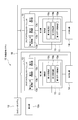
- FIG. 1 is a diagram showing the configuration of a production monitoring system according to an embodiment of the present invention.
- the production monitoring system 10 includes a plurality of processing machines 11, a computer system 12 for collecting production information from the processing machines 11, and a programmable controller unit (PLC) interposed between the computer system 12 and each processing machine 11. 13 and an extractor 14 as a product sorting unit provided for each processing machine 11.
- PLC programmable controller unit
- the processing machine 11 is typically a molding machine, a cutting machine, a press machine or the like. Each processing machine 11 has a control unit 15.
- the production information collected by the computer system 12 includes information as monitoring data, for example, molding cycle time in the processing machine 11, production number / production lot, molding condition / cooling water temperature / molding temperature (mold temperature / Water pipe temperature), molding machine environment / factory temperature etc.
- the programmable controller unit 13 controls the processing machine 11 in response to the request of the computer system 12 and also controls data (monitoring data) from a so-called retrofitted measuring instrument or the like which is not originally provided in the processing machine 11 Send to 12
- the control unit 15 and the programmable controller unit 13 send production information to the computer system 12 via the communication path 19.
- the communication path 19 includes not only a wired communication path but also a wireless communication path.
- the computer system 12 collects production information from the control unit 15 of the processing machine 11 in the factory, the programmable controller unit 13 installed in the processing machine 11, and the like.
- the computer system 12 has a display unit 12a that displays the collected production information in real time.
- the control unit 15 acquires a plurality of types of monitoring data from the processing machine 11 in real time, more specifically, a first data acquisition unit 15a for each product processed by the processing machine 11, and a plurality of types of monitoring
- the first evaluation unit 15b evaluates each acquired monitoring data in real time, more specifically, for each product processed by the processing machine 11, based on each threshold of the data;
- a first storage unit 15c for storing threshold values in advance.
- the programmable controller unit 13 is a second data acquisition unit that acquires monitoring data (such as measurement data of the measuring device described above) from the processing machine 11 in real time, more specifically, for each product processed by the processing machine 11
- a second evaluation unit 13b that evaluates the acquired monitoring data in real time, more specifically, for each product processed by the processing machine 11, based on the threshold value of the monitoring data 13a and 13a;
- a second storage unit 13c that stores threshold values in advance and sequentially stores acquired monitoring data.
- the programmable controller unit 13 collects and evaluates monitoring data when monitoring data other than the monitoring data set in advance by the control unit 15 is required. This makes it possible to collect and evaluate monitoring data in an external-like form.
- the first evaluation unit 15 b and the second evaluation unit 13 b determine, for each product, whether at least one of the monitoring data of the plurality of types is out of the threshold range of the monitoring data. When out of the range, sorting data is sent to the pick-up machine 14 to separate the product corresponding to the monitoring data which is out of the threshold range from other products.
- the pick-up machine 14 separates the product processed by the processing machine 11 based on the evaluation result of each product by the first evaluation unit 15 b and the second evaluation unit 13 b. Specifically, when the sorting machine 14 receives sorting data from the first evaluation unit 15 b and the second evaluation unit 13 b, the monitoring machine 14 is out of the range of the threshold value. Products corresponding to are separated from other products (defective products).
- the pick-up machine 14 typically has a robot for taking out the product processed by the processing machine 11 from the processing machine 11, and when the robot is a non-defective product, it carries the product to a non-defective product line. Carry the product in a box to put the defective product into.
- a plurality of types of monitoring data when the processing machine 11 is a molding machine include incidental facility information such as mold temperature, mold internal pressure, dryer temperature, drying time, and resin temperature for molding (resin temperature in hopper ), Injection speed, cushion amount (cushion position), primary pressure (peak pressure), secondary pressure (peak pressure), holding time, charge time, molded product (product) weight, heating cylinder position temperature, nozzle tip temperature And molding machine main body information such as the temperature under the hopper (before plasticization).
- incidental facility information such as mold temperature, mold internal pressure, dryer temperature, drying time, and resin temperature for molding (resin temperature in hopper ), Injection speed, cushion amount (cushion position), primary pressure (peak pressure), secondary pressure (peak pressure), holding time, charge time, molded product (product) weight, heating cylinder position temperature, nozzle tip temperature
- molding machine main body information such as the temperature under the hopper (before plasticization).
- Table 1 shows an example of a plurality of types of monitoring data and respective thresholds of the monitoring data.
- the processing machine 11 is a molding machine is illustrated.
- a holding pressure is applied in the injection process to stably produce a molded product, and a molten resin is left at the tip of the plunger to transmit the pressure.
- the amount of cushion means the amount of resin.
- the primary pressure is a pressure required to push out the resin
- the secondary pressure refers to a pressure which is maintained until the resin is solidified after being filled.
- the shape of the molded article is substantially determined by the setting conditions of the primary pressure and the secondary pressure.
- the pressure holding time is a time for applying a secondary pressure.
- mold temperature, mold internal pressure, molding resin temperature (in-hopper resin temperature), injection temperature, injection speed, cushion amount (cushion position), primary pressure (peak pressure), secondary Pressure (peak pressure), pressure holding time, charge time, molded product (product) weight, heating cylinder position temperature and nozzle tip temperature are acquired by the first data acquisition unit 15a of the control unit 15 of the processing machine 11 It is monitoring data.
- the hopper lower temperature is monitoring data acquired by the second data acquiring unit 13 a such as the programmable controller unit 13.
- FIG. 2 is a flowchart showing an example of the operation of the control unit 15.
- the control unit 15 causes the first data acquisition unit 15a to acquire the plurality of types of monitoring data for each product processed by the processing machine 11 (step 201), and transmits the data to the computer system 12 (step 202).
- the first evaluation unit 15b of the control unit 15 determines, for each product, whether each acquired monitoring data is within the range of each threshold of the monitoring data (Step 203). This determination typically determines whether at least one of a plurality of types of monitoring data is outside the threshold range of the monitoring data.
- the control unit 15 generates sorting data for sorting the product processed by 11 in the processing machine based on the determination result of the first evaluation unit 15b for each product (step 204), and takes it out as the removal machine 14 (Step 205) to notify the computer system 12 that it is out of the threshold range (step 206).
- This fractionated data typically corresponds to a product corresponding to monitoring data that is out of the range of the threshold when at least one of several types of monitoring data is out of the range of the threshold of the monitoring data. It is data to separate from other products.
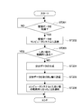
- FIG. 3 is a flowchart showing an example of the operation of the programmable controller unit 13.
- the programmable controller unit 13 causes the second data acquisition unit 13a to acquire predetermined monitoring data from the processing machine 11 for each product (step 301), and the monitoring data is stored in the second storage unit 13c for a predetermined period. Hold (step 302).
- the second evaluation unit 13b of the programmable controller unit 13 determines that one monitoring data (that is, monitoring data of one product among a plurality of products) is determined once in a predetermined period, that is, a plurality of monitoring data. It is determined whether it is within the threshold range (steps 303 and 304).
- the programmable controller unit 13 When the second evaluation unit 13b determines that the second evaluation unit 13b is out of the range of the threshold in the step 304, the programmable controller unit 13 generates separation data for separating the product processed by the processing machine (step 305). It sends it to the pick-up machine 14 (step 306) and notifies the computer system 12 that it is out of the range of the threshold (step 307), and at the same time the monitoring data held in the second storage unit 13c is Typically, it transmits collectively (step 308). By thus transmitting monitoring data in a batch, the load on the programmable controller unit 13 can be reduced.
- FIG. 4 is a flowchart showing an example of the operation of the computer system 12.
- the computer system 12 receives monitoring data from the control unit 15 and the programmable controller unit 13 (step 401), stores the monitoring data (step 402), and displays the monitoring data on the display unit 12a (step 403).
- the computer system 12 When receiving the notification out of the threshold range from the control unit 15 or the programmable controller unit 13 (step 404), the computer system 12 performs a predetermined notification and monitoring data that is out of the threshold range. Are displayed on the display unit 12a (step 405).
- the predetermined notification may be performed by, for example, a patrol light, or a predetermined notification sound may be output from a speaker or the like.
- the operator moves to the pick-up machine 14 according to the above notification or display, and can visually check the separated products, that is, the products considered to be defective products, so that the cause of failure of the defective products can be investigated.
- the operator typically checks the sorted products visually or the like, and if it is determined that the product is non-defective, the computer system 12 can review the threshold (step 406). For example, the worker sets the threshold value that is the basis of the defect to a new threshold value determined to be non-defective at an input unit (not shown) of the computer system 12.
- a threshold may be set by an operator, but may be set by the computer system 12 according to a predetermined rule.
- the newly set threshold is transmitted from the computer system 12 to the control unit 15 or the programmable controller unit 13 (step 407).
- the control unit 15 and the programmable controller unit 13 rewrite the threshold value transmitted so far from the previous threshold value (not shown).
- FIG. 5 shows a display form of monitoring data displayed on the display unit 12 a of the computer system 12.
- the display mode includes a second display mode in addition to the first display mode shown in FIG.
- the first display mode and the second display mode can be switched typically by a predetermined operation by the operator.
- each axis A is displayed with predetermined values of each value (monitored value) of a plurality of types of monitor data at a predetermined interval from the central point C.
- a connecting straight line L linking is displayed on the upper side as point data D, and adjacent point data D is connected, and a line L upper and a lower limit concentrically with the center point C indicating the upper and lower thresholds of each monitoring data. L low is displayed.
- the point data D is displayed on the screen (indicated by a dotted line in FIG. 5), but the point data D is displayed in a color different from that of the other data, thereby characterizing the monitoring data that is out of the threshold range. Can be displayed.
- the worker can confirm the product regarded as a defective product, and the worker can surely grasp the monitoring data which is out of the range of the threshold value by the display shown in FIG.
- each value (monitoring value) of a plurality of types of monitoring data is displayed at predetermined intervals in a radial manner from the central point C, so that the number of monitoring data changes significantly. It is possible to easily display the monitoring data on a limited screen. Also, by configuring to display lines L upper and L low indicating the upper limit and lower limit of the threshold value of each monitoring data concentrically with the central point C, the relative values of each monitoring data within the threshold value can be displayed. It is possible to understand the situation.
- FIG. 6 conceptually shows the display mode as shown in FIG.
- monitoring data on a mold used in the processing machine 11 is displayed in the area 61
- monitoring data on a material used in the processing machine 11 is displayed in the area 62
- the hopper 63 relates to a hopper used in the processing machine 11 Monitoring data is displayed.
- monitoring is determined as a defective product on the first display mode in which the upper limit and the lower limit of the threshold value at the initial value or at a predetermined timing are displayed concentrically.
- monitoring data 72 point data including data is mapped and displayed.
- the present invention is not limited to the above embodiment.
- a molding machine has been illustrated as a processing machine, but the present invention can be applied to a processing machine such as a cutting machine or a press machine.
- control unit is incorporated in the processing machine.
- control unit may be independent or the function of the control unit may be incorporated in the computer system.
- the display form of the monitoring data displayed on the display unit of the computer system is not limited to the above embodiment, and various displays are possible. Further, in the present invention, the worker is not limited to a person, and may of course be a robot.
Landscapes
- Engineering & Computer Science (AREA)
- Manufacturing & Machinery (AREA)
- Business, Economics & Management (AREA)
- General Physics & Mathematics (AREA)
- Physics & Mathematics (AREA)
- Tourism & Hospitality (AREA)
- General Business, Economics & Management (AREA)
- Marketing (AREA)
- Primary Health Care (AREA)
- Strategic Management (AREA)
- General Health & Medical Sciences (AREA)
- Economics (AREA)
- Human Resources & Organizations (AREA)
- Health & Medical Sciences (AREA)
- Theoretical Computer Science (AREA)
- General Engineering & Computer Science (AREA)
- Quality & Reliability (AREA)
- Automation & Control Theory (AREA)
- General Factory Administration (AREA)
- Management, Administration, Business Operations System, And Electronic Commerce (AREA)
Applications Claiming Priority (2)
| Application Number | Priority Date | Filing Date | Title |
|---|---|---|---|
| JP2017170276A JP7134453B2 (ja) | 2017-09-05 | 2017-09-05 | 生産監視システム及び生産監視方法 |
| JP2017-170276 | 2017-09-05 |
Publications (1)
| Publication Number | Publication Date |
|---|---|
| WO2019049669A1 true WO2019049669A1 (ja) | 2019-03-14 |
Family
ID=65633864
Family Applications (1)
| Application Number | Title | Priority Date | Filing Date |
|---|---|---|---|
| PCT/JP2018/031038 Ceased WO2019049669A1 (ja) | 2017-09-05 | 2018-08-22 | 生産監視システム及び生産監視方法 |
Country Status (2)
| Country | Link |
|---|---|
| JP (1) | JP7134453B2 (https=) |
| WO (1) | WO2019049669A1 (https=) |
Families Citing this family (3)
| Publication number | Priority date | Publication date | Assignee | Title |
|---|---|---|---|---|
| JP7262762B2 (ja) * | 2019-06-03 | 2023-04-24 | 株式会社Kmc | 生産監視装置、生産監視システム、生産監視方法及びプログラム |
| EP4122637B1 (en) | 2020-03-17 | 2025-08-27 | Mitsubishi Electric Corporation | Laser processing system |
| JP7660886B2 (ja) * | 2021-06-25 | 2025-04-14 | 株式会社Kmc | 受電装置、センサデバイス、給電システム及び受電方法 |
Citations (8)
| Publication number | Priority date | Publication date | Assignee | Title |
|---|---|---|---|---|
| JPH07178654A (ja) * | 1993-12-21 | 1995-07-18 | Canon Inc | 製造プロセス工程の生産管理システム |
| JPH1198491A (ja) * | 1997-09-19 | 1999-04-09 | Fit:Kk | 監視装置 |
| JP2007157007A (ja) * | 2005-12-08 | 2007-06-21 | Ricoh Co Ltd | 製造プロセス監視制御装置と監視制御方法及び記憶媒体 |
| JP2009093498A (ja) * | 2007-10-10 | 2009-04-30 | Toshiba Corp | 工程履歴表示システム、生産管理方法、及び生産管理用プログラム |
| JP2010039733A (ja) * | 2008-08-05 | 2010-02-18 | Toshiba Corp | 製造プロセスの監視方法、監視プログラム、監視システムおよび製品の製造方法 |
| JP2012027834A (ja) * | 2010-07-27 | 2012-02-09 | Hitachi Ltd | 生産プラント監視装置及びシステム、圧延プラント監視装置及びシステム、生産プラント遠隔監視方法、並びに圧延プラント遠隔監視方法 |
| JP2012159942A (ja) * | 2011-01-31 | 2012-08-23 | Omron Corp | データ収集装置、並びに、該データ収集装置の制御方法および制御プログラム |
| JP2015152943A (ja) * | 2014-02-10 | 2015-08-24 | オムロン株式会社 | 品質管理装置及びその制御方法 |
Family Cites Families (4)
| Publication number | Priority date | Publication date | Assignee | Title |
|---|---|---|---|---|
| JPH05304695A (ja) * | 1992-04-28 | 1993-11-16 | Toshiba Corp | プログラマブルコントローラ装置 |
| JP3365490B2 (ja) | 1999-02-25 | 2003-01-14 | 日本電気株式会社 | 集合型予測装置 |
| JP4880943B2 (ja) | 2005-08-09 | 2012-02-22 | 株式会社立花エレテック | 工程管理システムおよびその方法 |
| JP6211468B2 (ja) | 2014-06-12 | 2017-10-11 | 株式会社日立製作所 | 監視制御システム及び監視制御方法 |
-
2017
- 2017-09-05 JP JP2017170276A patent/JP7134453B2/ja active Active
-
2018
- 2018-08-22 WO PCT/JP2018/031038 patent/WO2019049669A1/ja not_active Ceased
Patent Citations (8)
| Publication number | Priority date | Publication date | Assignee | Title |
|---|---|---|---|---|
| JPH07178654A (ja) * | 1993-12-21 | 1995-07-18 | Canon Inc | 製造プロセス工程の生産管理システム |
| JPH1198491A (ja) * | 1997-09-19 | 1999-04-09 | Fit:Kk | 監視装置 |
| JP2007157007A (ja) * | 2005-12-08 | 2007-06-21 | Ricoh Co Ltd | 製造プロセス監視制御装置と監視制御方法及び記憶媒体 |
| JP2009093498A (ja) * | 2007-10-10 | 2009-04-30 | Toshiba Corp | 工程履歴表示システム、生産管理方法、及び生産管理用プログラム |
| JP2010039733A (ja) * | 2008-08-05 | 2010-02-18 | Toshiba Corp | 製造プロセスの監視方法、監視プログラム、監視システムおよび製品の製造方法 |
| JP2012027834A (ja) * | 2010-07-27 | 2012-02-09 | Hitachi Ltd | 生産プラント監視装置及びシステム、圧延プラント監視装置及びシステム、生産プラント遠隔監視方法、並びに圧延プラント遠隔監視方法 |
| JP2012159942A (ja) * | 2011-01-31 | 2012-08-23 | Omron Corp | データ収集装置、並びに、該データ収集装置の制御方法および制御プログラム |
| JP2015152943A (ja) * | 2014-02-10 | 2015-08-24 | オムロン株式会社 | 品質管理装置及びその制御方法 |
Also Published As
| Publication number | Publication date |
|---|---|
| JP2019046293A (ja) | 2019-03-22 |
| JP7134453B2 (ja) | 2022-09-12 |
Similar Documents
| Publication | Publication Date | Title |
|---|---|---|
| JP6616375B2 (ja) | 状態判定装置 | |
| US12186965B2 (en) | Method for product guidance in a stretch blow molding and/or filling system, and stretch blow molding and/or filling system for bottles | |
| KR101487162B1 (ko) | 실시간 프레스금형 제품 생산 모니터링 시스템 및 방법 | |
| CN112020415A (zh) | 用于可视化或评估过程状态的方法和装置 | |
| WO2019049669A1 (ja) | 生産監視システム及び生産監視方法 | |
| CN118401826A (zh) | 用于执行容器检查装置的设定操作的方法和容器检查装置 | |
| US20150019157A1 (en) | Method For Evaluating A Measurement Result Of A Thermal Analysis, As Well As Use Of The Method, Computer Unit, Computer Program Product And System For Performing The Method | |
| JP7725927B2 (ja) | 成形管理装置 | |
| US20250060320A1 (en) | Method for carrying out a setting operation of a container inspection apparatus, and container inspection apparatus | |
| CN115401888B (zh) | 成形机管理装置 | |
| WO2021215222A1 (ja) | 成形システム、異常予測装置、異常予測方法、プログラム及び学習済みモデル | |
| US20170291343A1 (en) | Molding system | |
| JP4871874B2 (ja) | 成形容器を検査し区分けするシステム及び方法 | |
| US5323837A (en) | Method of determining unacceptable deviations from process parameters | |
| WO2020246518A1 (ja) | 生産監視装置、生産監視システム、生産監視方法及びプログラム | |
| US10882236B2 (en) | Molding system, molding apparatus, inspection apparatus, inspection method, and program | |
| CN114378638A (zh) | 刀具状态检测系统及方法 | |
| JP7286083B2 (ja) | 生産監視装置、生産監視方法及びプログラム | |
| JP4571044B2 (ja) | モニタリング表示装置および表示方法 | |
| WO2021256017A1 (ja) | コントローラ、システム、方法及びプログラム | |
| US20230311382A1 (en) | Display device for injection molding, injection molding machine, and management device for injection molding | |
| JPH0655421B2 (ja) | 成形機生産監視システム | |
| CN121246186A (zh) | 一种基于数理统计的注塑机产品监控质量过程的方法 | |
| CN117875786A (zh) | 卷烟产品质量管控方法、装置及介质 | |
| JPH0425426A (ja) | 射出成形機の制御方法及び装置 |
Legal Events
| Date | Code | Title | Description |
|---|---|---|---|
| 121 | Ep: the epo has been informed by wipo that ep was designated in this application |
Ref document number: 18854020 Country of ref document: EP Kind code of ref document: A1 |
|
| NENP | Non-entry into the national phase |
Ref country code: DE |
|
| 122 | Ep: pct application non-entry in european phase |
Ref document number: 18854020 Country of ref document: EP Kind code of ref document: A1 |