WO2019049669A1 - Manufacturing monitoring system and manufacturing monitoring method - Google Patents
Manufacturing monitoring system and manufacturing monitoring method Download PDFInfo
- Publication number
- WO2019049669A1 WO2019049669A1 PCT/JP2018/031038 JP2018031038W WO2019049669A1 WO 2019049669 A1 WO2019049669 A1 WO 2019049669A1 JP 2018031038 W JP2018031038 W JP 2018031038W WO 2019049669 A1 WO2019049669 A1 WO 2019049669A1
- Authority
- WO
- WIPO (PCT)
- Prior art keywords
- monitoring data
- data
- monitoring
- threshold
- product
- Prior art date
Links
Images


Classifications
-
- G—PHYSICS
- G05—CONTROLLING; REGULATING
- G05B—CONTROL OR REGULATING SYSTEMS IN GENERAL; FUNCTIONAL ELEMENTS OF SUCH SYSTEMS; MONITORING OR TESTING ARRANGEMENTS FOR SUCH SYSTEMS OR ELEMENTS
- G05B19/00—Programme-control systems
- G05B19/02—Programme-control systems electric
- G05B19/418—Total factory control, i.e. centrally controlling a plurality of machines, e.g. direct or distributed numerical control [DNC], flexible manufacturing systems [FMS], integrated manufacturing systems [IMS], computer integrated manufacturing [CIM]
-
- G—PHYSICS
- G06—COMPUTING; CALCULATING OR COUNTING
- G06Q—INFORMATION AND COMMUNICATION TECHNOLOGY [ICT] SPECIALLY ADAPTED FOR ADMINISTRATIVE, COMMERCIAL, FINANCIAL, MANAGERIAL OR SUPERVISORY PURPOSES; SYSTEMS OR METHODS SPECIALLY ADAPTED FOR ADMINISTRATIVE, COMMERCIAL, FINANCIAL, MANAGERIAL OR SUPERVISORY PURPOSES, NOT OTHERWISE PROVIDED FOR
- G06Q50/00—Systems or methods specially adapted for specific business sectors, e.g. utilities or tourism
- G06Q50/04—Manufacturing
-
- Y—GENERAL TAGGING OF NEW TECHNOLOGICAL DEVELOPMENTS; GENERAL TAGGING OF CROSS-SECTIONAL TECHNOLOGIES SPANNING OVER SEVERAL SECTIONS OF THE IPC; TECHNICAL SUBJECTS COVERED BY FORMER USPC CROSS-REFERENCE ART COLLECTIONS [XRACs] AND DIGESTS
- Y02—TECHNOLOGIES OR APPLICATIONS FOR MITIGATION OR ADAPTATION AGAINST CLIMATE CHANGE
- Y02P—CLIMATE CHANGE MITIGATION TECHNOLOGIES IN THE PRODUCTION OR PROCESSING OF GOODS
- Y02P90/00—Enabling technologies with a potential contribution to greenhouse gas [GHG] emissions mitigation
- Y02P90/02—Total factory control, e.g. smart factories, flexible manufacturing systems [FMS] or integrated manufacturing systems [IMS]
-
- Y—GENERAL TAGGING OF NEW TECHNOLOGICAL DEVELOPMENTS; GENERAL TAGGING OF CROSS-SECTIONAL TECHNOLOGIES SPANNING OVER SEVERAL SECTIONS OF THE IPC; TECHNICAL SUBJECTS COVERED BY FORMER USPC CROSS-REFERENCE ART COLLECTIONS [XRACs] AND DIGESTS
- Y02—TECHNOLOGIES OR APPLICATIONS FOR MITIGATION OR ADAPTATION AGAINST CLIMATE CHANGE
- Y02P—CLIMATE CHANGE MITIGATION TECHNOLOGIES IN THE PRODUCTION OR PROCESSING OF GOODS
- Y02P90/00—Enabling technologies with a potential contribution to greenhouse gas [GHG] emissions mitigation
- Y02P90/30—Computing systems specially adapted for manufacturing
Definitions
- the present invention relates to a production monitoring system and a production monitoring method for monitoring production by a processing machine such as a molding machine, a cutting machine, or a press machine.
- Patent Document 1 discloses a technology for collecting data on quality characteristics in the manufacturing process, extracting data to be detected from the data, monitoring the occurrence of abnormal tendency from these data, and further determining the severity thereof. It is disclosed.
- Patent Document 1 With the technology described in Patent Document 1, the occurrence of abnormal tendency and its severity can be known, but since data on quality characteristics are collected in time units (eg, paragraph 0018), defective products are the next process May flow to
- the object of the present invention is to provide a production monitoring system which can reliably prevent a defective product from flowing to the next process, can investigate the defect cause of the defective product, and can predict and prevent the occurrence of defects. And provide a production monitoring method.
- a production monitoring system includes a data acquisition unit that acquires multiple types of monitoring data from a processing machine for each product processed by the processing machine, and the monitoring data.
- An evaluation unit that evaluates the acquired monitoring data for each product based on the threshold value of the item; and sorting the product processed by the processing machine based on an evaluation result for each product by the evaluation unit.
- the product sorting unit and the product sorting unit sort the product corresponding to the monitoring data which is out of the range of the threshold from other products, a predetermined notification is performed and the range is out of the range of the threshold
- a computer system that characterizes and displays the monitored data.
- each monitoring data of the processing machine is evaluated based on each threshold value of plural types of monitoring data, and processing is performed by the processing machine based on the evaluation result for each product. Since the sorted products are separated, defective products can be reliably prevented from flowing to the next process. Further, when the product sorting unit sorts the product corresponding to the monitoring data which is out of the range of the threshold value from the other products, the computer system performs a predetermined notification and is out of the range of the threshold value. Since the supervised monitoring data is characterized and displayed, the operator can confirm the product regarded as a defective product and can surely grasp the supervised data which is out of the range of the threshold value. Therefore, the cause of the defect of the defective product can be determined from the classified defective products and the monitoring data which is out of the range of the threshold value. Furthermore, the occurrence of defects can be predicted and prevented from the evaluation results by the evaluation unit.
- the product sorting unit determines that at least one of the plurality of types of monitoring data is out of a threshold range of the monitoring data
- the product sorting unit Separate the product corresponding to the monitoring data that is out of the range from the other products. This makes it possible to more reliably prevent defective products from flowing to the next step.
- the production monitoring system further includes a storage unit storing a threshold of the monitoring data, and a storage unit storing the monitoring data when the monitoring data is out of the range of the threshold. And means for changing the threshold value.
- the threshold value can be set to a more appropriate value, and defective products can be more reliably prevented from flowing to the next step.
- a production monitoring method acquires multiple types of monitoring data from a processing machine for each product processed by the processing machine, and the acquired monitoring data is the threshold of each of the monitoring data. It is determined for each one product whether it is within the range of values, and separation data for separating the product processed by the processing machine is generated based on the determination result for each one product, and the range of the threshold value
- separation data is generated which separates the product corresponding to the monitoring data that has become out of the other products
- a predetermined notification is typically performed in a computer system that collects production information from the processing machine, and The monitoring data out of the threshold range is characterized and displayed.
- the classification data is out of the range of the threshold of the monitoring data. It is data for separating the product corresponding to the monitoring data which became The method further sorts the product processed by the processor based on the sorting data. This makes it possible to more reliably prevent defective products from flowing to the next step.
- the threshold value can be set to a more appropriate value, and defective products can be more reliably prevented from flowing to the next step.
- the production monitoring program includes the steps of acquiring, from each processing machine, plural types of monitoring data for each product processed by the processing machine, and the acquired monitoring data corresponds to the monitoring data. Determining, for each product, whether it is within a threshold range, generating separation data for separating a product processed by the processing machine based on the determination result, and the threshold When sorting data for sorting a product corresponding to monitoring data which is out of the range from other products is generated, a predetermined notification is performed in a computer system that collects production information from the processing machine, and Characterizing and displaying the monitoring data that is out of the threshold range.
- a production monitoring system includes a programmable controller unit interposed between a computer system that collects production information from the processing machine and the processing machine, and the programmable controller unit includes the processing machine.
- Monitoring data acquired sequentially by at least a predetermined period, and evaluating whether the monitoring data is within the range of the threshold value once in the predetermined period from the monitoring data sequentially acquired by the processing machine
- the monitoring data may be sent to the computer system at least for the predetermined period held when the monitoring data is out of the range of the threshold.
- the present invention it is possible to reliably prevent a defective product from flowing to the next process, and to determine the cause of the defect of the defective product, and to predict and prevent the occurrence of a defect.
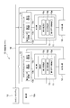
- FIG. 1 is a diagram showing the configuration of a production monitoring system according to an embodiment of the present invention.
- the production monitoring system 10 includes a plurality of processing machines 11, a computer system 12 for collecting production information from the processing machines 11, and a programmable controller unit (PLC) interposed between the computer system 12 and each processing machine 11. 13 and an extractor 14 as a product sorting unit provided for each processing machine 11.
- PLC programmable controller unit
- the processing machine 11 is typically a molding machine, a cutting machine, a press machine or the like. Each processing machine 11 has a control unit 15.
- the production information collected by the computer system 12 includes information as monitoring data, for example, molding cycle time in the processing machine 11, production number / production lot, molding condition / cooling water temperature / molding temperature (mold temperature / Water pipe temperature), molding machine environment / factory temperature etc.
- the programmable controller unit 13 controls the processing machine 11 in response to the request of the computer system 12 and also controls data (monitoring data) from a so-called retrofitted measuring instrument or the like which is not originally provided in the processing machine 11 Send to 12
- the control unit 15 and the programmable controller unit 13 send production information to the computer system 12 via the communication path 19.
- the communication path 19 includes not only a wired communication path but also a wireless communication path.
- the computer system 12 collects production information from the control unit 15 of the processing machine 11 in the factory, the programmable controller unit 13 installed in the processing machine 11, and the like.
- the computer system 12 has a display unit 12a that displays the collected production information in real time.
- the control unit 15 acquires a plurality of types of monitoring data from the processing machine 11 in real time, more specifically, a first data acquisition unit 15a for each product processed by the processing machine 11, and a plurality of types of monitoring
- the first evaluation unit 15b evaluates each acquired monitoring data in real time, more specifically, for each product processed by the processing machine 11, based on each threshold of the data;
- a first storage unit 15c for storing threshold values in advance.
- the programmable controller unit 13 is a second data acquisition unit that acquires monitoring data (such as measurement data of the measuring device described above) from the processing machine 11 in real time, more specifically, for each product processed by the processing machine 11
- a second evaluation unit 13b that evaluates the acquired monitoring data in real time, more specifically, for each product processed by the processing machine 11, based on the threshold value of the monitoring data 13a and 13a;
- a second storage unit 13c that stores threshold values in advance and sequentially stores acquired monitoring data.
- the programmable controller unit 13 collects and evaluates monitoring data when monitoring data other than the monitoring data set in advance by the control unit 15 is required. This makes it possible to collect and evaluate monitoring data in an external-like form.
- the first evaluation unit 15 b and the second evaluation unit 13 b determine, for each product, whether at least one of the monitoring data of the plurality of types is out of the threshold range of the monitoring data. When out of the range, sorting data is sent to the pick-up machine 14 to separate the product corresponding to the monitoring data which is out of the threshold range from other products.
- the pick-up machine 14 separates the product processed by the processing machine 11 based on the evaluation result of each product by the first evaluation unit 15 b and the second evaluation unit 13 b. Specifically, when the sorting machine 14 receives sorting data from the first evaluation unit 15 b and the second evaluation unit 13 b, the monitoring machine 14 is out of the range of the threshold value. Products corresponding to are separated from other products (defective products).
- the pick-up machine 14 typically has a robot for taking out the product processed by the processing machine 11 from the processing machine 11, and when the robot is a non-defective product, it carries the product to a non-defective product line. Carry the product in a box to put the defective product into.
- a plurality of types of monitoring data when the processing machine 11 is a molding machine include incidental facility information such as mold temperature, mold internal pressure, dryer temperature, drying time, and resin temperature for molding (resin temperature in hopper ), Injection speed, cushion amount (cushion position), primary pressure (peak pressure), secondary pressure (peak pressure), holding time, charge time, molded product (product) weight, heating cylinder position temperature, nozzle tip temperature And molding machine main body information such as the temperature under the hopper (before plasticization).
- incidental facility information such as mold temperature, mold internal pressure, dryer temperature, drying time, and resin temperature for molding (resin temperature in hopper ), Injection speed, cushion amount (cushion position), primary pressure (peak pressure), secondary pressure (peak pressure), holding time, charge time, molded product (product) weight, heating cylinder position temperature, nozzle tip temperature
- molding machine main body information such as the temperature under the hopper (before plasticization).
- Table 1 shows an example of a plurality of types of monitoring data and respective thresholds of the monitoring data.
- the processing machine 11 is a molding machine is illustrated.
- a holding pressure is applied in the injection process to stably produce a molded product, and a molten resin is left at the tip of the plunger to transmit the pressure.
- the amount of cushion means the amount of resin.
- the primary pressure is a pressure required to push out the resin
- the secondary pressure refers to a pressure which is maintained until the resin is solidified after being filled.
- the shape of the molded article is substantially determined by the setting conditions of the primary pressure and the secondary pressure.
- the pressure holding time is a time for applying a secondary pressure.
- mold temperature, mold internal pressure, molding resin temperature (in-hopper resin temperature), injection temperature, injection speed, cushion amount (cushion position), primary pressure (peak pressure), secondary Pressure (peak pressure), pressure holding time, charge time, molded product (product) weight, heating cylinder position temperature and nozzle tip temperature are acquired by the first data acquisition unit 15a of the control unit 15 of the processing machine 11 It is monitoring data.
- the hopper lower temperature is monitoring data acquired by the second data acquiring unit 13 a such as the programmable controller unit 13.
- FIG. 2 is a flowchart showing an example of the operation of the control unit 15.
- the control unit 15 causes the first data acquisition unit 15a to acquire the plurality of types of monitoring data for each product processed by the processing machine 11 (step 201), and transmits the data to the computer system 12 (step 202).
- the first evaluation unit 15b of the control unit 15 determines, for each product, whether each acquired monitoring data is within the range of each threshold of the monitoring data (Step 203). This determination typically determines whether at least one of a plurality of types of monitoring data is outside the threshold range of the monitoring data.
- the control unit 15 generates sorting data for sorting the product processed by 11 in the processing machine based on the determination result of the first evaluation unit 15b for each product (step 204), and takes it out as the removal machine 14 (Step 205) to notify the computer system 12 that it is out of the threshold range (step 206).
- This fractionated data typically corresponds to a product corresponding to monitoring data that is out of the range of the threshold when at least one of several types of monitoring data is out of the range of the threshold of the monitoring data. It is data to separate from other products.
- FIG. 3 is a flowchart showing an example of the operation of the programmable controller unit 13.
- the programmable controller unit 13 causes the second data acquisition unit 13a to acquire predetermined monitoring data from the processing machine 11 for each product (step 301), and the monitoring data is stored in the second storage unit 13c for a predetermined period. Hold (step 302).
- the second evaluation unit 13b of the programmable controller unit 13 determines that one monitoring data (that is, monitoring data of one product among a plurality of products) is determined once in a predetermined period, that is, a plurality of monitoring data. It is determined whether it is within the threshold range (steps 303 and 304).
- the programmable controller unit 13 When the second evaluation unit 13b determines that the second evaluation unit 13b is out of the range of the threshold in the step 304, the programmable controller unit 13 generates separation data for separating the product processed by the processing machine (step 305). It sends it to the pick-up machine 14 (step 306) and notifies the computer system 12 that it is out of the range of the threshold (step 307), and at the same time the monitoring data held in the second storage unit 13c is Typically, it transmits collectively (step 308). By thus transmitting monitoring data in a batch, the load on the programmable controller unit 13 can be reduced.
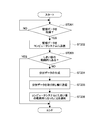
- FIG. 4 is a flowchart showing an example of the operation of the computer system 12.
- the computer system 12 receives monitoring data from the control unit 15 and the programmable controller unit 13 (step 401), stores the monitoring data (step 402), and displays the monitoring data on the display unit 12a (step 403).
- the computer system 12 When receiving the notification out of the threshold range from the control unit 15 or the programmable controller unit 13 (step 404), the computer system 12 performs a predetermined notification and monitoring data that is out of the threshold range. Are displayed on the display unit 12a (step 405).
- the predetermined notification may be performed by, for example, a patrol light, or a predetermined notification sound may be output from a speaker or the like.
- the operator moves to the pick-up machine 14 according to the above notification or display, and can visually check the separated products, that is, the products considered to be defective products, so that the cause of failure of the defective products can be investigated.
- the operator typically checks the sorted products visually or the like, and if it is determined that the product is non-defective, the computer system 12 can review the threshold (step 406). For example, the worker sets the threshold value that is the basis of the defect to a new threshold value determined to be non-defective at an input unit (not shown) of the computer system 12.
- a threshold may be set by an operator, but may be set by the computer system 12 according to a predetermined rule.
- the newly set threshold is transmitted from the computer system 12 to the control unit 15 or the programmable controller unit 13 (step 407).
- the control unit 15 and the programmable controller unit 13 rewrite the threshold value transmitted so far from the previous threshold value (not shown).
- FIG. 5 shows a display form of monitoring data displayed on the display unit 12 a of the computer system 12.
- the display mode includes a second display mode in addition to the first display mode shown in FIG.
- the first display mode and the second display mode can be switched typically by a predetermined operation by the operator.
- each axis A is displayed with predetermined values of each value (monitored value) of a plurality of types of monitor data at a predetermined interval from the central point C.
- a connecting straight line L linking is displayed on the upper side as point data D, and adjacent point data D is connected, and a line L upper and a lower limit concentrically with the center point C indicating the upper and lower thresholds of each monitoring data. L low is displayed.
- the point data D is displayed on the screen (indicated by a dotted line in FIG. 5), but the point data D is displayed in a color different from that of the other data, thereby characterizing the monitoring data that is out of the threshold range. Can be displayed.
- the worker can confirm the product regarded as a defective product, and the worker can surely grasp the monitoring data which is out of the range of the threshold value by the display shown in FIG.
- each value (monitoring value) of a plurality of types of monitoring data is displayed at predetermined intervals in a radial manner from the central point C, so that the number of monitoring data changes significantly. It is possible to easily display the monitoring data on a limited screen. Also, by configuring to display lines L upper and L low indicating the upper limit and lower limit of the threshold value of each monitoring data concentrically with the central point C, the relative values of each monitoring data within the threshold value can be displayed. It is possible to understand the situation.
- FIG. 6 conceptually shows the display mode as shown in FIG.
- monitoring data on a mold used in the processing machine 11 is displayed in the area 61
- monitoring data on a material used in the processing machine 11 is displayed in the area 62
- the hopper 63 relates to a hopper used in the processing machine 11 Monitoring data is displayed.
- monitoring is determined as a defective product on the first display mode in which the upper limit and the lower limit of the threshold value at the initial value or at a predetermined timing are displayed concentrically.
- monitoring data 72 point data including data is mapped and displayed.
- the present invention is not limited to the above embodiment.
- a molding machine has been illustrated as a processing machine, but the present invention can be applied to a processing machine such as a cutting machine or a press machine.
- control unit is incorporated in the processing machine.
- control unit may be independent or the function of the control unit may be incorporated in the computer system.
- the display form of the monitoring data displayed on the display unit of the computer system is not limited to the above embodiment, and various displays are possible. Further, in the present invention, the worker is not limited to a person, and may of course be a robot.
Abstract
For the purpose of reliably preventing a defective product from proceeding to a subsequent process, finding the cause of the defect of the defective product, and predicting and preventing the occurrence of the defect, this manufacturing monitoring system 10 is provided with: a first data acquisition unit 15a for acquiring, from a machine tool 11, a plurality of types of monitoring data for each product processed by the machine tool 11; a first evaluation unit 15b for evaluating, on the basis of threshold values of each of the monitoring data, each of the acquired monitoring data for each of the products; an extraction device 14 for classifying the products processed by the machine tool 11 on the basis of the result of the evaluation performed by the first evaluation unit 15b for each of the products; and a computer system 12 for, when the extraction device 14 has classified the products associated with the monitoring data outside the range of the threshold values separately from other products, carrying out a prescribed notification and displaying the monitoring data outside the range of the threshold values in an accentuated manner.
Description
本発明は、成形機や切削加工機、プレス機などの加工機による生産を監視する生産監視システム及び生産監視方法に関する。
The present invention relates to a production monitoring system and a production monitoring method for monitoring production by a processing machine such as a molding machine, a cutting machine, or a press machine.
製造ラインにおいては、製造プロセス中で品質特性に関する温度、圧力などの実測データなどを収集し、これを集中的に管理することが行われている。
In the manufacturing line, it is practiced to collect and control measured data such as temperature and pressure related to quality characteristics in the manufacturing process.
特許文献1には、製造過程における品質特性に関するデータを収集し、データから検知対象となるデータを抽出し、これらのデータから異常傾向の発生を監視し、更にその深刻度の判断をする技術が開示されている。
Patent Document 1 discloses a technology for collecting data on quality characteristics in the manufacturing process, extracting data to be detected from the data, monitoring the occurrence of abnormal tendency from these data, and further determining the severity thereof. It is disclosed.
特許文献1に記載された技術では、異常傾向の発生とその深刻度を知ることができるが、品質特性に関するデータを時間単位で収集していることから(段落0018など)、不良品が次工程に流れる可能性がある。
With the technology described in Patent Document 1, the occurrence of abnormal tendency and its severity can be known, but since data on quality characteristics are collected in time units (eg, paragraph 0018), defective products are the next process May flow to
以上のような事情に鑑み、本発明の目的は、不良品が次工程に流れることを確実に防止でき、しかも不良品の不良原因を究明でき、かつ、不良発生を予知・予防できる生産監視システム及び生産監視方法を提供することを目的とする。
In view of the above-described circumstances, the object of the present invention is to provide a production monitoring system which can reliably prevent a defective product from flowing to the next process, can investigate the defect cause of the defective product, and can predict and prevent the occurrence of defects. And provide a production monitoring method.
上記目的を達成するため、本発明の一形態に係る生産監視システムは、加工機から複数種類の監視データを前記加工機が加工した一製品ごとに取得するデータ取得部と、前記監視データのそれぞれのしきい値に基づき、前記取得されたそれぞれの監視データを前記一製品ごとに評価する評価部と、前記評価部による一製品ごとの評価結果に基づき前記加工機により加工された製品を分別する製品分別部と、前記製品分別部が前記しきい値の範囲外となった監視データに対応する製品を他の製品から分別したとき、所定の報知を行い、かつ、前記しきい値の範囲外となった監視データを特徴付けて表示するコンピュータシステムとを具備する。
In order to achieve the above object, a production monitoring system according to an aspect of the present invention includes a data acquisition unit that acquires multiple types of monitoring data from a processing machine for each product processed by the processing machine, and the monitoring data. An evaluation unit that evaluates the acquired monitoring data for each product based on the threshold value of the item; and sorting the product processed by the processing machine based on an evaluation result for each product by the evaluation unit. When the product sorting unit and the product sorting unit sort the product corresponding to the monitoring data which is out of the range of the threshold from other products, a predetermined notification is performed and the range is out of the range of the threshold And a computer system that characterizes and displays the monitored data.
本発明では、加工機が加工した一製品ごとに、複数種類の監視データのそれぞれのしきい値に基づき加工機のそれぞれの監視データを評価し、一製品ごとの評価結果に基づき加工機により加工された製品を分別しているので、不良品が次工程に流れることを確実に防止できる。
また、製品分別部が前記しきい値の範囲外となった監視データに対応する製品を他の製品から分別したとき、コンピュータシステムにおいて、所定の報知を行い、かつ、しきい値の範囲外となった監視データを特徴付けて表示するので、作業者は不良品とみなされた製品を確認でき、またしきい値の範囲外となった監視データを確実に把握できる。よって、分別された不良品及びしきい値の範囲外となった監視データから、不良品の不良原因を究明できる。
更に、評価部による評価結果から、不良発生を予知・予防できる。 In the present invention, for each product processed by the processing machine, each monitoring data of the processing machine is evaluated based on each threshold value of plural types of monitoring data, and processing is performed by the processing machine based on the evaluation result for each product. Since the sorted products are separated, defective products can be reliably prevented from flowing to the next process.
Further, when the product sorting unit sorts the product corresponding to the monitoring data which is out of the range of the threshold value from the other products, the computer system performs a predetermined notification and is out of the range of the threshold value. Since the supervised monitoring data is characterized and displayed, the operator can confirm the product regarded as a defective product and can surely grasp the supervised data which is out of the range of the threshold value. Therefore, the cause of the defect of the defective product can be determined from the classified defective products and the monitoring data which is out of the range of the threshold value.
Furthermore, the occurrence of defects can be predicted and prevented from the evaluation results by the evaluation unit.
本発明の一形態に係る生産監視システムは、前記製品分別部は、前記複数種類の監視データのうち少なくとも1つの監視データが当該監視データのしきい値の範囲外であるときに、当該しきい値の範囲外となった監視データに対応する製品を他の製品から分別する。
これにより、不良品が次工程に流れることをより確実に防止できる。 In the production monitoring system according to one aspect of the present invention, when the product sorting unit determines that at least one of the plurality of types of monitoring data is out of a threshold range of the monitoring data, the product sorting unit Separate the product corresponding to the monitoring data that is out of the range from the other products.
This makes it possible to more reliably prevent defective products from flowing to the next step.
本発明の一形態に係る生産監視システムは、更に、前記監視データのしきい値を記憶する記憶部と、前記監視データがしきい値の範囲外となったときに、前記記憶部に記憶された当該しきい値を変更するための手段とを具備する。
これにより、しきい値をより適切な値にすることができ、不良品が次工程に流れることをより確実に防止できる。 The production monitoring system according to one aspect of the present invention further includes a storage unit storing a threshold of the monitoring data, and a storage unit storing the monitoring data when the monitoring data is out of the range of the threshold. And means for changing the threshold value.
As a result, the threshold value can be set to a more appropriate value, and defective products can be more reliably prevented from flowing to the next step.
本発明の一形態に係る生産監視方法は、加工機から複数種類の監視データを前記加工機が加工した一製品ごとに取得し、前記取得したそれぞれの監視データが前記監視データのそれぞれのしきい値の範囲内にあるかを前記一製品ごとに判定し、前記一製品ごとの判定結果に基づき前記加工機により加工された製品を分別するための分別データを生成し、前記しきい値の範囲外となった監視データに対応する製品を他の製品から分別する分別データが生成されたとき、典型的には前記加工機から生産情報を収集するコンピュータシステムにおいて、所定の報知を行い、かつ、前記しきい値の範囲外となった監視データを特徴付けて表示する。
これにより、不良品が次工程に流れることを確実に防止でき、また不良品の不良原因を究明でき、更に不良発生を予知・予防できる。 A production monitoring method according to an aspect of the present invention acquires multiple types of monitoring data from a processing machine for each product processed by the processing machine, and the acquired monitoring data is the threshold of each of the monitoring data. It is determined for each one product whether it is within the range of values, and separation data for separating the product processed by the processing machine is generated based on the determination result for each one product, and the range of the threshold value When separation data is generated which separates the product corresponding to the monitoring data that has become out of the other products, a predetermined notification is typically performed in a computer system that collects production information from the processing machine, and The monitoring data out of the threshold range is characterized and displayed.
As a result, it is possible to reliably prevent a defective product from flowing to the next process, to investigate the defect cause of the defective product, and to predict and prevent the occurrence of a defect.
本発明の一形態に係る生産監視方法は、前記分別データが、前記複数種類の監視データのうち少なくとも1つが当該監視データのしきい値の範囲外であるときに、当該しきい値の範囲外となった監視データに対応する製品を他の製品から分別するためのデータである。当該方法は、更に、前記分別データに基づき前記加工機により加工された製品を分別する。
これにより、不良品が次工程に流れることをより確実に防止できる。 In the production monitoring method according to one aspect of the present invention, when at least one of the plurality of types of monitoring data is out of the threshold range of the monitoring data, the classification data is out of the range of the threshold of the monitoring data. It is data for separating the product corresponding to the monitoring data which became The method further sorts the product processed by the processor based on the sorting data.
This makes it possible to more reliably prevent defective products from flowing to the next step.
本発明の一形態に係る生産監視方法は、前記監視データがしきい値の範囲外となったときに分別された製品の外観などを評価し、前記評価結果に基づき前記範囲外としたしきい値を見直す。
これにより、しきい値をより適切な値にすることができ、不良品が次工程に流れることをより確実に防止できる。 In the production monitoring method according to one aspect of the present invention, when the monitoring data falls outside the range of the threshold, the appearance etc. of the separated products are evaluated, and the threshold is determined outside the range based on the evaluation result. Review the value.
As a result, the threshold value can be set to a more appropriate value, and defective products can be more reliably prevented from flowing to the next step.
本発明の一形態に係る生産監視用プログラムは、加工機から複数種類の監視データを前記加工機が加工した一製品ごとに取得するステップと、前記取得したそれぞれの監視データが前記監視データのそれぞれのしきい値の範囲内にあるかを前記一製品ごとに判定するステップと、前記判定結果に基づき前記加工機により加工された製品を分別するための分別データを生成するステップと、前記しきい値の範囲外となった監視データに対応する製品を他の製品から分別する分別データが生成されたとき、前記加工機から生産情報を収集するコンピュータシステムにおいて、所定の報知を行わせ、かつ、前記しきい値の範囲外となった監視データを特徴付けて表示さえるステップとをコンピュータに実行させる。
The production monitoring program according to an aspect of the present invention includes the steps of acquiring, from each processing machine, plural types of monitoring data for each product processed by the processing machine, and the acquired monitoring data corresponds to the monitoring data. Determining, for each product, whether it is within a threshold range, generating separation data for separating a product processed by the processing machine based on the determination result, and the threshold When sorting data for sorting a product corresponding to monitoring data which is out of the range from other products is generated, a predetermined notification is performed in a computer system that collects production information from the processing machine, and Characterizing and displaying the monitoring data that is out of the threshold range.
本発明の一形態に係る生産監視システムは、前記加工機から生産情報を収集するコンピュータシステムと前記加工機との間に介在されたプログラマブルコントローラユニットを具備し、前記プログラマブルコントローラユニットは、前記加工機により順次取得する監視データを少なくとも所定期間分保持し、前記加工機により順次取得する監視データから前記所定期間に1度、当該監視データが前記しきい値の範囲内にあるかを評価する前記評価部として機能し、前記監視データが前記しきい値の範囲外であるときに、少なくとも前記保持した前記所定期間分の監視データを前記コンピュータシステムに送るように構成してもよい。
これにより、プログラマブルコントローラユニットからコンピュータシステムに送るデータの量を減らし、コンピュータシステム側での処理負担を低減することができる。 A production monitoring system according to an aspect of the present invention includes a programmable controller unit interposed between a computer system that collects production information from the processing machine and the processing machine, and the programmable controller unit includes the processing machine. Monitoring data acquired sequentially by at least a predetermined period, and evaluating whether the monitoring data is within the range of the threshold value once in the predetermined period from the monitoring data sequentially acquired by the processing machine The monitoring data may be sent to the computer system at least for the predetermined period held when the monitoring data is out of the range of the threshold.
Thus, the amount of data to be sent from the programmable controller unit to the computer system can be reduced, and the processing load on the computer system side can be reduced.
本発明によれば、不良品が次工程に流れることを確実に防止でき、しかも不良品の不良原因を究明でき、かつ、不良発生を予知・予防できる。
According to the present invention, it is possible to reliably prevent a defective product from flowing to the next process, and to determine the cause of the defect of the defective product, and to predict and prevent the occurrence of a defect.
以下、図面を参照しながら、本発明の実施形態を説明する。
図1は、本発明の一実施形態に係る生産監視システムの構成を示す図である。
生産監視システム10は、複数の加工機11と、これらの加工機11から生産情報を収集するコンピュータシステム12と、コンピュータシステム12と各加工機11との間に介在されたプログラマブルコントローラユニット(PLC)13と、加工機11ごとに設けられた製品分別部としての取り出し機14とを有する。 Hereinafter, embodiments of the present invention will be described with reference to the drawings.
FIG. 1 is a diagram showing the configuration of a production monitoring system according to an embodiment of the present invention.
The production monitoring system 10 includes a plurality ofprocessing machines 11, a computer system 12 for collecting production information from the processing machines 11, and a programmable controller unit (PLC) interposed between the computer system 12 and each processing machine 11. 13 and an extractor 14 as a product sorting unit provided for each processing machine 11.
図1は、本発明の一実施形態に係る生産監視システムの構成を示す図である。
生産監視システム10は、複数の加工機11と、これらの加工機11から生産情報を収集するコンピュータシステム12と、コンピュータシステム12と各加工機11との間に介在されたプログラマブルコントローラユニット(PLC)13と、加工機11ごとに設けられた製品分別部としての取り出し機14とを有する。 Hereinafter, embodiments of the present invention will be described with reference to the drawings.
FIG. 1 is a diagram showing the configuration of a production monitoring system according to an embodiment of the present invention.
The production monitoring system 10 includes a plurality of
加工機11としては、典型的には成形機や切削加工機、プレス機などである。加工機11は、それぞれ、制御部15を有する。
The processing machine 11 is typically a molding machine, a cutting machine, a press machine or the like. Each processing machine 11 has a control unit 15.
コンピュータシステム12が収集する生産情報とは、監視データとしての情報も含むものであり、例えば加工機11における成形サイクル時間、生産数/生産ロット、成形条件/冷却水温度/成形温度(金型温度/水管温度)、成形機環境/工場温度などである。
The production information collected by the computer system 12 includes information as monitoring data, for example, molding cycle time in the processing machine 11, production number / production lot, molding condition / cooling water temperature / molding temperature (mold temperature / Water pipe temperature), molding machine environment / factory temperature etc.
プログラマブルコントローラユニット13は、コンピュータシステム12の要求に応じて、加工機11を制御すると共に、加工機11に当初から備えられていない、いわゆる後付けの測定器などからのデータ(監視データ)をコンピュータシステム12に送る。
The programmable controller unit 13 controls the processing machine 11 in response to the request of the computer system 12 and also controls data (monitoring data) from a so-called retrofitted measuring instrument or the like which is not originally provided in the processing machine 11 Send to 12
制御部15及びプログラマブルコントローラユニット13は、コンピュータシステム12に対して通信路19を介して生産情報を送る。通信路19は、有線の通信路ばかりでなく、無線の通信路が含まれる。
The control unit 15 and the programmable controller unit 13 send production information to the computer system 12 via the communication path 19. The communication path 19 includes not only a wired communication path but also a wireless communication path.
コンピュータシステム12は、工場内の加工機11の制御部15や加工機11に設置されたプログラマブルコントローラユニット13などから生産情報を収集する。コンピュータシステム12は、収集した生産情報をリアルタイムに表示する表示部12aを有する。
The computer system 12 collects production information from the control unit 15 of the processing machine 11 in the factory, the programmable controller unit 13 installed in the processing machine 11, and the like. The computer system 12 has a display unit 12a that displays the collected production information in real time.
制御部15は、当該加工機11から複数種類の監視データをリアルタイムに、より具体的には加工機11により加工される一製品ごとに取得する第1のデータ取得部15aと、複数種類の監視データのそれぞれのしきい値に基づき、取得されたそれぞれの監視データをリアルタイムに、より具体的には加工機11により加工される一製品ごとに評価する第1の評価部15bと、上記のしきい値を予め記憶する第1の記憶部15cとを有する。
The control unit 15 acquires a plurality of types of monitoring data from the processing machine 11 in real time, more specifically, a first data acquisition unit 15a for each product processed by the processing machine 11, and a plurality of types of monitoring The first evaluation unit 15b evaluates each acquired monitoring data in real time, more specifically, for each product processed by the processing machine 11, based on each threshold of the data; And a first storage unit 15c for storing threshold values in advance.
プログラマブルコントローラユニット13は、加工機11から監視データ(上記の測定器の測定データなど)をリアルタイムに、より具体的には加工機11により加工される一製品ごとに取得する第2のデータ取得部13aと、監視データのしきい値に基づき、取得された監視データをリアルタイムに、より具体的には加工機11により加工される一製品ごとに評価する第2の評価部13bと、上記のしきい値を予め記憶し、また取得した監視データを順次記憶する第2の記憶部13cとを有する。プログラマブルコントローラユニット13は、制御部15で予め設定されている監視データ以外の監視データが必要になった場合に、その監視データを収集し、評価する。これにより、いわば外付けのような形態で監視データを収集、評価が可能となる。
The programmable controller unit 13 is a second data acquisition unit that acquires monitoring data (such as measurement data of the measuring device described above) from the processing machine 11 in real time, more specifically, for each product processed by the processing machine 11 A second evaluation unit 13b that evaluates the acquired monitoring data in real time, more specifically, for each product processed by the processing machine 11, based on the threshold value of the monitoring data 13a and 13a; And a second storage unit 13c that stores threshold values in advance and sequentially stores acquired monitoring data. The programmable controller unit 13 collects and evaluates monitoring data when monitoring data other than the monitoring data set in advance by the control unit 15 is required. This makes it possible to collect and evaluate monitoring data in an external-like form.
第1の評価部15b及び第2の評価部13bは、一製品ごとに、複数種類の監視データのうち少なくとも1つの監視データが当該監視データのしきい値の範囲外であるかを判断し、範囲外であるときには、しきい値の範囲外となった監視データに対応する製品を他の製品から分別させる分別データを取り出し機14に送る。
The first evaluation unit 15 b and the second evaluation unit 13 b determine, for each product, whether at least one of the monitoring data of the plurality of types is out of the threshold range of the monitoring data. When out of the range, sorting data is sent to the pick-up machine 14 to separate the product corresponding to the monitoring data which is out of the threshold range from other products.
取り出し機14は、第1の評価部15b及び第2の評価部13bによる一製品ごとの評価結果に基づき加工機11により加工された製品を分別する。具体的には、取り出し機14は、取り出し機14は、第1の評価部15b及び第2の評価部13bより分別データが送られたときに、当該しきい値の範囲外となった監視データに対応する製品を他の製品(不良品)から分別する。取り出し機14は、典型的には、加工機11により加工された製品を加工機11から取り出すロボットを有し、このロボットが良品の場合には良品のラインにその製品を運び、不良品の場合には不良品を入れる箱にその製品を運ぶ。
The pick-up machine 14 separates the product processed by the processing machine 11 based on the evaluation result of each product by the first evaluation unit 15 b and the second evaluation unit 13 b. Specifically, when the sorting machine 14 receives sorting data from the first evaluation unit 15 b and the second evaluation unit 13 b, the monitoring machine 14 is out of the range of the threshold value. Products corresponding to are separated from other products (defective products). The pick-up machine 14 typically has a robot for taking out the product processed by the processing machine 11 from the processing machine 11, and when the robot is a non-defective product, it carries the product to a non-defective product line. Carry the product in a box to put the defective product into.
加工機11が成形機である場合の複数種類の監視データとしては、金型温度、金型内圧力、乾燥機温度、乾燥時間などの付帯設備情報と、成形用の樹脂温度(ホッパー内樹脂温度)、射出速度、クッション量(クッション位置)、一次圧(ピーク圧)、二次圧(ピーク圧)、保圧時間、チャージ時間、成形品(製品)重量、加熱筒各位置温度、ノズル先端温度、ホッパー下(可塑化前)温度などの成形機本体情報とがある。
A plurality of types of monitoring data when the processing machine 11 is a molding machine include incidental facility information such as mold temperature, mold internal pressure, dryer temperature, drying time, and resin temperature for molding (resin temperature in hopper ), Injection speed, cushion amount (cushion position), primary pressure (peak pressure), secondary pressure (peak pressure), holding time, charge time, molded product (product) weight, heating cylinder position temperature, nozzle tip temperature And molding machine main body information such as the temperature under the hopper (before plasticization).
表1に複数種類の監視データ及びこれら監視データのそれぞれのしきい値の一例を示す。ここでは、加工機11が成形機である場合を例示している。
Table 1 shows an example of a plurality of types of monitoring data and respective thresholds of the monitoring data. Here, the case where the processing machine 11 is a molding machine is illustrated.
[表1]
 [Table 1]
成形品を安定生産するために射出工程で保圧をかけ、その圧力を伝達させるためにプランジャ先端部に溶融樹脂を残す。クッション量とは、その樹脂量をいう。
A holding pressure is applied in the injection process to stably produce a molded product, and a molten resin is left at the tip of the plunger to transmit the pressure. The amount of cushion means the amount of resin.
プラスチックを射出成型するためには、スクリューから押し出すには圧力が必要であり、
一次圧とは樹脂を押し出すのに必要な圧力であり、一次圧で押された樹脂がキャビティに充填されると、二次圧(保圧)に切り替える。二次圧(保圧)とは、充填されてからその樹脂が固化するまでの間保持する圧力をいう。一次圧と二次圧の設定条件で、成形品の形がほぼ決まる。 In order to injection-mold plastic, pressure is required to push it out of the screw,
The primary pressure is a pressure required to push out the resin, and when the resin pressed by the primary pressure is filled in the cavity, the pressure is switched to the secondary pressure (holding pressure). The secondary pressure (holding pressure) refers to a pressure which is maintained until the resin is solidified after being filled. The shape of the molded article is substantially determined by the setting conditions of the primary pressure and the secondary pressure.
保圧時間とは、二次圧をかける時間である。
The pressure holding time is a time for applying a secondary pressure.
これらの監視データのうち、金型温度、金型内圧力、成形用の樹脂温度(ホッパー内樹脂温度)、射出温度、射出速度、クッション量(クッション位置)、一次圧(ピーク圧)、二次圧(ピーク圧)、保圧時間、チャージ時間、成形品(製品)重量、加熱筒各位置温度及びノズル先端温度は、加工機11の制御部15の第1のデータ取得部15aにより取得される監視データである。
監視データのうち、ホッパー下温度は、プログラマブルコントローラユニット13などの第2のデータ取得部13aにより取得される監視データである。 Among these monitoring data, mold temperature, mold internal pressure, molding resin temperature (in-hopper resin temperature), injection temperature, injection speed, cushion amount (cushion position), primary pressure (peak pressure), secondary Pressure (peak pressure), pressure holding time, charge time, molded product (product) weight, heating cylinder position temperature and nozzle tip temperature are acquired by the firstdata acquisition unit 15a of the control unit 15 of the processing machine 11 It is monitoring data.
Among the monitoring data, the hopper lower temperature is monitoring data acquired by the seconddata acquiring unit 13 a such as the programmable controller unit 13.
監視データのうち、ホッパー下温度は、プログラマブルコントローラユニット13などの第2のデータ取得部13aにより取得される監視データである。 Among these monitoring data, mold temperature, mold internal pressure, molding resin temperature (in-hopper resin temperature), injection temperature, injection speed, cushion amount (cushion position), primary pressure (peak pressure), secondary Pressure (peak pressure), pressure holding time, charge time, molded product (product) weight, heating cylinder position temperature and nozzle tip temperature are acquired by the first
Among the monitoring data, the hopper lower temperature is monitoring data acquired by the second
図2は制御部15の動作の一例を示すフローチャートである。
FIG. 2 is a flowchart showing an example of the operation of the control unit 15.
制御部15は、第1のデータ取得部15aが上記の複数種類の監視データを、加工機11が加工した一製品ごとに取得し(ステップ201)、コンピュータシステム12に送信する(ステップ202)。
The control unit 15 causes the first data acquisition unit 15a to acquire the plurality of types of monitoring data for each product processed by the processing machine 11 (step 201), and transmits the data to the computer system 12 (step 202).
制御部15の第1の評価部15bは、取得したそれぞれの監視データが監視データのそれぞれのしきい値の範囲内にあるかを一製品ごとに判定する(ステップ203)。この判定は、典型的には、複数種類の監視データのうち少なくとも1つが当該監視データのしきい値の範囲外であるかを判定する。
The first evaluation unit 15b of the control unit 15 determines, for each product, whether each acquired monitoring data is within the range of each threshold of the monitoring data (Step 203). This determination typically determines whether at least one of a plurality of types of monitoring data is outside the threshold range of the monitoring data.
制御部15は、第1の評価部15bが一製品ごとの判定結果に基づき、加工機に11より加工された製品を分別するための分別データを生成し(ステップ204)、それを取り出し機14に送信し(ステップ205)、コンピュータシステム12にしきい値の範囲外になったことを通知する(ステップ206)。この分別データは、典型的には、数種類の監視データのうち少なくとも1つが当該監視データのしきい値の範囲外のときに、当該しきい値の範囲外となった監視データに対応する製品を他の製品から分別するためのデータである。
The control unit 15 generates sorting data for sorting the product processed by 11 in the processing machine based on the determination result of the first evaluation unit 15b for each product (step 204), and takes it out as the removal machine 14 (Step 205) to notify the computer system 12 that it is out of the threshold range (step 206). This fractionated data typically corresponds to a product corresponding to monitoring data that is out of the range of the threshold when at least one of several types of monitoring data is out of the range of the threshold of the monitoring data. It is data to separate from other products.
図3はプログラマブルコントローラユニット13の動作の一例を示すフローチャートである。
FIG. 3 is a flowchart showing an example of the operation of the programmable controller unit 13.
プログラマブルコントローラユニット13は、第2のデータ取得部13aが、一製品ごとに、加工機11より所定の監視データを取得し(ステップ301)、その監視データを第2の記憶部13cに所定期間分保持する(ステップ302)。
The programmable controller unit 13 causes the second data acquisition unit 13a to acquire predetermined monitoring data from the processing machine 11 for each product (step 301), and the monitoring data is stored in the second storage unit 13c for a predetermined period. Hold (step 302).
プログラマブルコントローラユニット13の第2の評価部13bは、所定期間に1度、つまり複数個の監視データにつき1個の監視データ(すなわち複数の製品のうち1個の製品の監視データ)が所定のしきい値の範囲内にあるかを判定する(ステップ303、304)。
The second evaluation unit 13b of the programmable controller unit 13 determines that one monitoring data (that is, monitoring data of one product among a plurality of products) is determined once in a predetermined period, that is, a plurality of monitoring data. It is determined whether it is within the threshold range (steps 303 and 304).
プログラマブルコントローラユニット13は、第2の評価部13bがステップ304でしきい値の範囲外と判定すると、加工機により加工された製品を分別するための分別データを生成し(ステップ305)、それを取り出し機14に送信し(ステップ306)、コンピュータシステム12にはしきい値の範囲外になったことを通知する(ステップ307)と共に、それまでに第2の記憶部13cに保持した監視データを典型的には一括で送信する(ステップ308)。このように一括で監視データを送信するように構成することで、プログラマブルコントローラユニット13の負荷を低減することができる。
When the second evaluation unit 13b determines that the second evaluation unit 13b is out of the range of the threshold in the step 304, the programmable controller unit 13 generates separation data for separating the product processed by the processing machine (step 305). It sends it to the pick-up machine 14 (step 306) and notifies the computer system 12 that it is out of the range of the threshold (step 307), and at the same time the monitoring data held in the second storage unit 13c is Typically, it transmits collectively (step 308). By thus transmitting monitoring data in a batch, the load on the programmable controller unit 13 can be reduced.
図4はコンピュータシステム12の動作の一例を示すフローチャートである。
FIG. 4 is a flowchart showing an example of the operation of the computer system 12.
コンピュータシステム12は、制御部15及びプログラマブルコントローラユニット13より監視データを受信し(ステップ401)、蓄積し(ステップ402)、表示部12aに監視データを表示する(ステップ403)。
The computer system 12 receives monitoring data from the control unit 15 and the programmable controller unit 13 (step 401), stores the monitoring data (step 402), and displays the monitoring data on the display unit 12a (step 403).
コンピュータシステム12は、制御部15又はプログラマブルコントローラユニット13より上記のしきい値範囲外の通知を受信すると(ステップ404)、所定の報知を行い、かつ、しきい値の範囲外となった監視データを表示部12aに特徴付けて表示する(ステップ405)。所定の報知は、例えばパトライトにより行ってもよいし、スピーカなどから所定の報知音を出力してもよい。
When receiving the notification out of the threshold range from the control unit 15 or the programmable controller unit 13 (step 404), the computer system 12 performs a predetermined notification and monitoring data that is out of the threshold range. Are displayed on the display unit 12a (step 405). The predetermined notification may be performed by, for example, a patrol light, or a predetermined notification sound may be output from a speaker or the like.
作業者は、上記の報知や表示に応じて、取り出し機14まで移動して、分別された製品、すなわち不良品とみなされた製品を目視などにより確認でき、不良品の不良原因を究明できる。
The operator moves to the pick-up machine 14 according to the above notification or display, and can visually check the separated products, that is, the products considered to be defective products, so that the cause of failure of the defective products can be investigated.
作業者は、典型的には、分別された製品を目視などにより確認し、良品であると判断する場合には、コンピュータシステム12においてしきい値の見直しができる(ステップ406)。例えば、作業者は、コンピュータシステム12の入力部(図示せず)において、不良の基となったしきい値を、良品と判定される新たなしきい値に設定する。そのようなしきい値の設定は作業者が行っても良いが、コンピュータシステム12が所定のルールに従って設定してもよい。
The operator typically checks the sorted products visually or the like, and if it is determined that the product is non-defective, the computer system 12 can review the threshold (step 406). For example, the worker sets the threshold value that is the basis of the defect to a new threshold value determined to be non-defective at an input unit (not shown) of the computer system 12. Such a threshold may be set by an operator, but may be set by the computer system 12 according to a predetermined rule.
ステップ406でしきい値が見直されたときに、新たに設定されたしきい値がコンピュータシステム12より制御部15又はプログラマブルコントローラユニット13に送信される(ステップ407)。制御部15及びプログラマブルコントローラユニット13では、それまでのしきい値から送信されたしきい値に書き換えられる(図示せず)。
When the threshold is reviewed in step 406, the newly set threshold is transmitted from the computer system 12 to the control unit 15 or the programmable controller unit 13 (step 407). The control unit 15 and the programmable controller unit 13 rewrite the threshold value transmitted so far from the previous threshold value (not shown).
図5にコンピュータシステム12の表示部12aに表示される監視データの表示形態を示す。なお、表示形態には、図5に示す第1の表示モードの他に第2の表示モードがある。第1の表示モードと第2の表示モードとは典型的には作業者による所定の操作によって切り替えることができる。
FIG. 5 shows a display form of monitoring data displayed on the display unit 12 a of the computer system 12. The display mode includes a second display mode in addition to the first display mode shown in FIG. The first display mode and the second display mode can be switched typically by a predetermined operation by the operator.
・第1の表示モード
図5に示すように、表示部12aには、複数種類の監視データの各値(監視値)が中心点Cより放射線状に所定の間隔で表示されたそれぞれの軸A上に点データDとして表示され、隣接する点データDを結ぶように連結直線Llinkingが表示され、中心点Cと同心円状に各監視データのしきい値の上限及び下限を示す線Lupper及びLlowが表示される。 First Display Mode As shown in FIG. 5, on thedisplay unit 12a, each axis A is displayed with predetermined values of each value (monitored value) of a plurality of types of monitor data at a predetermined interval from the central point C. A connecting straight line L linking is displayed on the upper side as point data D, and adjacent point data D is connected, and a line L upper and a lower limit concentrically with the center point C indicating the upper and lower thresholds of each monitoring data. L low is displayed.
図5に示すように、表示部12aには、複数種類の監視データの各値(監視値)が中心点Cより放射線状に所定の間隔で表示されたそれぞれの軸A上に点データDとして表示され、隣接する点データDを結ぶように連結直線Llinkingが表示され、中心点Cと同心円状に各監視データのしきい値の上限及び下限を示す線Lupper及びLlowが表示される。 First Display Mode As shown in FIG. 5, on the
監視データがしきい値の上限又は下限を超えた場合或いは上記のしきい値範囲外の通知を受信した場合に、図5に示す線Lupperと線Llowとの間の領域から外れた領域に点データDが表示される(図5では点線で表示)が、この点データDについては他のデータとは異なる色で表示することで、しきい値の範囲外となった監視データを特徴付けて表示することができる。
An area out of the area between the line L upper and the line L low shown in FIG. 5 when the monitoring data exceeds the upper limit or the lower limit of the threshold or when the notification outside the above threshold range is received. The point data D is displayed on the screen (indicated by a dotted line in FIG. 5), but the point data D is displayed in a color different from that of the other data, thereby characterizing the monitoring data that is out of the threshold range. Can be displayed.
これにより、作業者は不良品とみなされた製品を確認でき、また図5に示した表示によって、作業者はしきい値の範囲外となった監視データを確実に把握できる。
As a result, the worker can confirm the product regarded as a defective product, and the worker can surely grasp the monitoring data which is out of the range of the threshold value by the display shown in FIG.
本実施形態では、特に、複数種類の監視データの各値(監視値)を中心点Cより放射線状に所定の間隔で表示するように構成したことで、監視データの数が大きく変化しても、限られた画面上に監視データを把握し易く表示することが可能である。また、中心点Cと同心円状に各監視データのしきい値の上限及び下限を示す線Lupper及びLlowを表示するように構成することで、しきい値内にある各監視データの相対的な状態を把握することが可能である。
In the present embodiment, in particular, each value (monitoring value) of a plurality of types of monitoring data is displayed at predetermined intervals in a radial manner from the central point C, so that the number of monitoring data changes significantly. It is possible to easily display the monitoring data on a limited screen. Also, by configuring to display lines L upper and L low indicating the upper limit and lower limit of the threshold value of each monitoring data concentrically with the central point C, the relative values of each monitoring data within the threshold value can be displayed. It is possible to understand the situation.
・第2の表示モード
図6は図5に示したような表示形態を概念的に示した図である。
例えば領域61には加工機11に使われる金型に関する監視データが表示され、領域62には加工機11に使われる材料に関する監視データが表示され、領域63には加工機11に使われるホッパーに関する監視データが表示される。 Second Display Mode FIG. 6 conceptually shows the display mode as shown in FIG.
For example, monitoring data on a mold used in theprocessing machine 11 is displayed in the area 61, monitoring data on a material used in the processing machine 11 is displayed in the area 62, and the hopper 63 relates to a hopper used in the processing machine 11 Monitoring data is displayed.
図6は図5に示したような表示形態を概念的に示した図である。
例えば領域61には加工機11に使われる金型に関する監視データが表示され、領域62には加工機11に使われる材料に関する監視データが表示され、領域63には加工機11に使われるホッパーに関する監視データが表示される。 Second Display Mode FIG. 6 conceptually shows the display mode as shown in FIG.
For example, monitoring data on a mold used in the
第2の表示モードは、図7に示すように、初期値乃至所定のタイミングにおけるしきい値の上限及び下限が同心円状に表示された第1の表示モード上に、不良品と判定された監視データを含む監視データ72(点データ)をマッピングして表示するモードである。
In the second display mode, as shown in FIG. 7, monitoring is determined as a defective product on the first display mode in which the upper limit and the lower limit of the threshold value at the initial value or at a predetermined timing are displayed concentrically. In this mode, monitoring data 72 (point data) including data is mapped and displayed.
このような第2の表示モードによって、加工機11において不良品が発生する要因、例えば金型がその要因なのか、或いは材料がその要因なのかなどを視覚的に把握することができる。これにより、より迅速にかつ的確に不良品の不良原因を究明でき、かつ、不良発生を予知・予防できる。
With such a second display mode, it is possible to visually grasp a factor causing defective products in the processing machine 11, for example, whether the factor is a mold or the factor. As a result, the cause of the defect of the defective product can be investigated more quickly and accurately, and the occurrence of the defect can be predicted and prevented.
なお、本発明は上記の実施形態には限定されない。
例えば、上記の実施形態では、加工機として成形機を例示して説明したが、切削加工機、プレス機などの加工機についても本発明を適用することができる。 The present invention is not limited to the above embodiment.
For example, in the above embodiment, a molding machine has been illustrated as a processing machine, but the present invention can be applied to a processing machine such as a cutting machine or a press machine.
上記の実施形態では、システム上にプログラマブルコントローラユニットを介在させた例を説明したが、プログラマブルコントローラユニットをこのような監視に用いないシステムにも本発明を適用することができる。
Although the above-mentioned embodiment explained an example which intervened a programmable controller unit on a system, the present invention is applicable also to a system which does not use a programmable controller unit for such monitoring.
上記の実施形態では、制御部が加工機内に組み込まれた構成であったが、本発明では、制御部を独立させても良いし、制御部の機能をコンピュータシステム内に組み込んでも構わない。
In the above embodiment, the control unit is incorporated in the processing machine. However, in the present invention, the control unit may be independent or the function of the control unit may be incorporated in the computer system.
コンピュータシステムの表示部に表示される監視データの表示形態も上記の実施形態には限定されず、様々な表示が可能である。
また、本発明では、作業者は人に限定されず、ロボットであっても勿論構わない。 The display form of the monitoring data displayed on the display unit of the computer system is not limited to the above embodiment, and various displays are possible.
Further, in the present invention, the worker is not limited to a person, and may of course be a robot.
10 :生産監視システム
11 :加工機
12 :コンピュータシステム
12a :表示部
13 :プログラマブルコントローラユニット
13a :第2のデータ取得部
13b :第2の評価部
13c :第2の記憶部
14 :取り出し機
15 :制御部
15a :第1のデータ取得部
15b :第1の評価部
15c :第1の記憶部 10: production monitoring system 11: processing machine 12:computer system 12a: display unit 13: programmable controller unit 13a: second data acquisition unit 13b: second evaluation unit 13c: second storage unit 14: extraction machine 15: Control unit 15a: first data acquisition unit 15b: first evaluation unit 15c: first storage unit
11 :加工機
12 :コンピュータシステム
12a :表示部
13 :プログラマブルコントローラユニット
13a :第2のデータ取得部
13b :第2の評価部
13c :第2の記憶部
14 :取り出し機
15 :制御部
15a :第1のデータ取得部
15b :第1の評価部
15c :第1の記憶部 10: production monitoring system 11: processing machine 12:
Claims (6)
- 加工機から複数種類の監視データを前記加工機が加工した一製品ごとに取得するデータ取得部と、
前記監視データのそれぞれのしきい値に基づき、前記取得されたそれぞれの監視データを前記一製品ごとに評価する評価部と、
前記評価部による一製品ごとの評価結果に基づき前記加工機により加工された製品を分別する製品分別部と、
前記製品分別部が前記しきい値の範囲外となった監視データに対応する製品を他の製品から分別したとき、所定の報知を行い、かつ、前記しきい値の範囲外となった監視データを特徴付けて表示するコンピュータシステムと
を具備する生産監視システム。 A data acquisition unit that acquires multiple types of monitoring data from a processing machine for each product processed by the processing machine;
An evaluation unit that evaluates each of the acquired monitoring data for each of the products based on each threshold value of the monitoring data;
A product sorting unit that sorts the product processed by the processing machine based on the evaluation result of each product by the evaluation unit;
When the product sorting unit sorts the product corresponding to the monitoring data which is out of the range of the threshold from other products, a predetermined notification is given and the monitoring data which is out of the range of the threshold A production monitoring system comprising: a computer system for characterizing and displaying. - 請求項1に記載の生産監視システムであって、
前記製品分別部は、前記複数種類の監視データのうち少なくとも1つの監視データが当該監視データのしきい値の範囲外であるときに、当該しきい値の範囲外となった監視データに対応する製品を他の製品から分別する
生産監視システム。 The production monitoring system according to claim 1, wherein
The product sorting unit corresponds to monitoring data which is out of the range of the threshold when at least one of the monitoring data of the plurality of types is out of the range of the threshold of the monitoring data. Production monitoring system that separates products from other products. - 請求項1又は2に記載の生産監視システムであって、更に、
前記監視データのしきい値を記憶する記憶部と、
前記監視データがしきい値の範囲外となったときに、前記記憶部に記憶された当該しきい値を変更するための手段と
を具備する生産監視システム。 The production monitoring system according to claim 1 or 2, further comprising:
A storage unit that stores a threshold value of the monitoring data;
Means for changing the threshold value stored in the storage unit when the monitoring data is out of the range of the threshold value. - 加工機から複数種類の監視データを前記加工機が加工した一製品ごとに取得し、
前記取得したそれぞれの監視データが前記監視データのそれぞれのしきい値の範囲内にあるかを前記一製品ごとに判定し、
前記一製品ごとの判定結果に基づき前記加工機により加工された製品を分別するための分別データを生成し、
前記しきい値の範囲外となった監視データに対応する製品を他の製品から分別する分別データが生成されたとき、所定の報知を行い、かつ、前記しきい値の範囲外となった監視データを特徴付けて表示する
生産監視方法。 Obtain multiple types of monitoring data from a processing machine for each product processed by the processing machine,
It is determined for each of the products whether or not each of the acquired monitoring data is within a threshold of each of the monitoring data,
The separation data for separating the product processed by the processing machine is generated based on the judgment result for each product,
When separation data is generated that separates the product corresponding to the monitoring data that is out of the threshold range from the other products, a predetermined notification is performed and the monitoring that is out of the range of the threshold Characterize and display data Production monitoring methods. - 請求項4に記載の生産監視方法であって、
前記分別データは、前記複数種類の監視データのうち少なくとも1つが当該監視データのしきい値の範囲外であるときに、当該しきい値の範囲外となった監視データに対応する製品を他の製品から分別するためのデータであり、
前記分別データに基づき前記加工機により加工された製品を分別する
生産監視方法。 The production monitoring method according to claim 4, wherein
The classification data is a product corresponding to monitoring data that is out of the range of the threshold when at least one of the plurality of types of monitoring data is out of the range of the threshold of the monitoring data. It is data to separate from products,
A production monitoring method of separating a product processed by the processing machine based on the classification data. - 請求項4又は5に記載の生産監視方法であって、
前記監視データがしきい値の範囲外となったときに分別された製品を評価し、
前記評価結果に基づき前記範囲外としたしきい値を見直す
生産監視方法。 The production monitoring method according to claim 4 or 5, wherein
Evaluate the sorted products when the monitoring data falls outside the threshold range,
A method of monitoring a threshold which is out of the range based on the evaluation result.
Applications Claiming Priority (2)
| Application Number | Priority Date | Filing Date | Title |
|---|---|---|---|
| JP2017-170276 | 2017-09-05 | ||
| JP2017170276A JP7134453B2 (en) | 2017-09-05 | 2017-09-05 | Production monitoring system and production monitoring method |
Publications (1)
| Publication Number | Publication Date |
|---|---|
| WO2019049669A1 true WO2019049669A1 (en) | 2019-03-14 |
Family
ID=65633864
Family Applications (1)
| Application Number | Title | Priority Date | Filing Date |
|---|---|---|---|
| PCT/JP2018/031038 WO2019049669A1 (en) | 2017-09-05 | 2018-08-22 | Manufacturing monitoring system and manufacturing monitoring method |
Country Status (2)
| Country | Link |
|---|---|
| JP (1) | JP7134453B2 (en) |
| WO (1) | WO2019049669A1 (en) |
Families Citing this family (2)
| Publication number | Priority date | Publication date | Assignee | Title |
|---|---|---|---|---|
| JP7262762B2 (en) * | 2019-06-03 | 2023-04-24 | 株式会社Kmc | PRODUCTION MONITORING DEVICE, PRODUCTION MONITORING SYSTEM, PRODUCTION MONITORING METHOD AND PROGRAM |
| WO2021186567A1 (en) | 2020-03-17 | 2021-09-23 | 三菱電機株式会社 | Laser processing system |
Citations (8)
| Publication number | Priority date | Publication date | Assignee | Title |
|---|---|---|---|---|
| JPH07178654A (en) * | 1993-12-21 | 1995-07-18 | Canon Inc | Production control system for manufacturing process |
| JPH1198491A (en) * | 1997-09-19 | 1999-04-09 | Fit:Kk | Supervisory equipment |
| JP2007157007A (en) * | 2005-12-08 | 2007-06-21 | Ricoh Co Ltd | Monitoring and controlling device for manufacturing process, monitoring and control method, and storage medium |
| JP2009093498A (en) * | 2007-10-10 | 2009-04-30 | Toshiba Corp | Process history display system, production management method and production management program |
| JP2010039733A (en) * | 2008-08-05 | 2010-02-18 | Toshiba Corp | Method, program and system for monitoring manufacturing process and method for manufacturing product |
| JP2012027834A (en) * | 2010-07-27 | 2012-02-09 | Hitachi Ltd | Production plant monitoring device and system, rolling plant monitoring device and system, production plant remote monitoring method, and rolling plant remote monitoring method |
| JP2012159942A (en) * | 2011-01-31 | 2012-08-23 | Omron Corp | Data storage device, and control method and control program of data storage device |
| JP2015152943A (en) * | 2014-02-10 | 2015-08-24 | オムロン株式会社 | Quality management device and control method therefor |
Family Cites Families (4)
| Publication number | Priority date | Publication date | Assignee | Title |
|---|---|---|---|---|
| JPH05304695A (en) * | 1992-04-28 | 1993-11-16 | Toshiba Corp | Programmable controller |
| JP3365490B2 (en) * | 1999-02-25 | 2003-01-14 | 日本電気株式会社 | Set prediction device |
| JP4880943B2 (en) * | 2005-08-09 | 2012-02-22 | 株式会社立花エレテック | Process management system and method |
| JP6211468B2 (en) * | 2014-06-12 | 2017-10-11 | 株式会社日立製作所 | Monitoring control system and monitoring control method |
-
2017
- 2017-09-05 JP JP2017170276A patent/JP7134453B2/en active Active
-
2018
- 2018-08-22 WO PCT/JP2018/031038 patent/WO2019049669A1/en active Application Filing
Patent Citations (8)
| Publication number | Priority date | Publication date | Assignee | Title |
|---|---|---|---|---|
| JPH07178654A (en) * | 1993-12-21 | 1995-07-18 | Canon Inc | Production control system for manufacturing process |
| JPH1198491A (en) * | 1997-09-19 | 1999-04-09 | Fit:Kk | Supervisory equipment |
| JP2007157007A (en) * | 2005-12-08 | 2007-06-21 | Ricoh Co Ltd | Monitoring and controlling device for manufacturing process, monitoring and control method, and storage medium |
| JP2009093498A (en) * | 2007-10-10 | 2009-04-30 | Toshiba Corp | Process history display system, production management method and production management program |
| JP2010039733A (en) * | 2008-08-05 | 2010-02-18 | Toshiba Corp | Method, program and system for monitoring manufacturing process and method for manufacturing product |
| JP2012027834A (en) * | 2010-07-27 | 2012-02-09 | Hitachi Ltd | Production plant monitoring device and system, rolling plant monitoring device and system, production plant remote monitoring method, and rolling plant remote monitoring method |
| JP2012159942A (en) * | 2011-01-31 | 2012-08-23 | Omron Corp | Data storage device, and control method and control program of data storage device |
| JP2015152943A (en) * | 2014-02-10 | 2015-08-24 | オムロン株式会社 | Quality management device and control method therefor |
Also Published As
| Publication number | Publication date |
|---|---|
| JP7134453B2 (en) | 2022-09-12 |
| JP2019046293A (en) | 2019-03-22 |
Similar Documents
| Publication | Publication Date | Title |
|---|---|---|
| JP6616375B2 (en) | State determination device | |
| US10391692B2 (en) | Injection molding system | |
| US20200391422A1 (en) | Method and device for visualizing or evaluating a process state | |
| JP4871874B2 (en) | System and method for inspecting and sorting molded containers | |
| US20220203597A1 (en) | Method for product guidance in a stretch blow molding and/or filling system, and stretch blow molding and/or filling system for bottles | |
| US9816869B2 (en) | Method for evaluating a measurement result of a thermal analysis, as well as use of the method, computer unit, computer program product and system for performing the method | |
| WO2019049669A1 (en) | Manufacturing monitoring system and manufacturing monitoring method | |
| KR101444205B1 (en) | A Molding Information Extraction Symtem of Emitting Mold Press | |
| WO2020246518A1 (en) | Production monitoring device, production monitoring system, production monitoring method, and program | |
| US20170291343A1 (en) | Molding system | |
| US5323837A (en) | Method of determining unacceptable deviations from process parameters | |
| WO2021215222A1 (en) | Molding system, anomaly prediction device, anomaly prediction method, program, and trained model | |
| US10882236B2 (en) | Molding system, molding apparatus, inspection apparatus, inspection method, and program | |
| JP7286083B2 (en) | PRODUCTION MONITORING DEVICE, PRODUCTION MONITORING METHOD AND PROGRAM | |
| JP6352579B1 (en) | Molding system, molding apparatus, inspection apparatus, inspection method and program | |
| DE102018212617A1 (en) | Process and production plant for processing a material | |
| WO2021256017A1 (en) | Controller, system, method, and program | |
| US20230311382A1 (en) | Display device for injection molding, injection molding machine, and management device for injection molding | |
| US20220379538A1 (en) | Molding Machine Management Device | |
| TWI681856B (en) | Automatic casting detection method capable of detecting die breakage | |
| JP2022129256A (en) | Checker for quality improvement | |
| JPH0655421B2 (en) | Molding machine production monitoring system | |
| Wiegand | Detailed Prediction of Product Quality for Advanced Process Control | |
| JPH0425426A (en) | Controlling method for injection molding machine and equipment | |
| KR20110000905A (en) | Trimming inspection system for rubber products and trimming management method using the same |
Legal Events
| Date | Code | Title | Description |
|---|---|---|---|
| 121 | Ep: the epo has been informed by wipo that ep was designated in this application |
Ref document number: 18854020 Country of ref document: EP Kind code of ref document: A1 |
|
| NENP | Non-entry into the national phase |
Ref country code: DE |
|
| 122 | Ep: pct application non-entry in european phase |
Ref document number: 18854020 Country of ref document: EP Kind code of ref document: A1 |