WO2019044624A1 - Composition de graisse - Google Patents
Composition de graisse Download PDFInfo
- Publication number
- WO2019044624A1 WO2019044624A1 PCT/JP2018/030988 JP2018030988W WO2019044624A1 WO 2019044624 A1 WO2019044624 A1 WO 2019044624A1 JP 2018030988 W JP2018030988 W JP 2018030988W WO 2019044624 A1 WO2019044624 A1 WO 2019044624A1
- Authority
- WO
- WIPO (PCT)
- Prior art keywords
- grease composition
- grease
- urea
- group
- thickener
- Prior art date
Links
Images


Classifications
-
- C—CHEMISTRY; METALLURGY
- C10—PETROLEUM, GAS OR COKE INDUSTRIES; TECHNICAL GASES CONTAINING CARBON MONOXIDE; FUELS; LUBRICANTS; PEAT
- C10M—LUBRICATING COMPOSITIONS; USE OF CHEMICAL SUBSTANCES EITHER ALONE OR AS LUBRICATING INGREDIENTS IN A LUBRICATING COMPOSITION
- C10M115/00—Lubricating compositions characterised by the thickener being a non-macromolecular organic compound other than a carboxylic acid or salt thereof
- C10M115/08—Lubricating compositions characterised by the thickener being a non-macromolecular organic compound other than a carboxylic acid or salt thereof containing nitrogen
-
- C—CHEMISTRY; METALLURGY
- C10—PETROLEUM, GAS OR COKE INDUSTRIES; TECHNICAL GASES CONTAINING CARBON MONOXIDE; FUELS; LUBRICANTS; PEAT
- C10M—LUBRICATING COMPOSITIONS; USE OF CHEMICAL SUBSTANCES EITHER ALONE OR AS LUBRICATING INGREDIENTS IN A LUBRICATING COMPOSITION
- C10M169/00—Lubricating compositions characterised by containing as components a mixture of at least two types of ingredient selected from base-materials, thickeners or additives, covered by the preceding groups, each of these compounds being essential
- C10M169/06—Mixtures of thickeners and additives
-
- C—CHEMISTRY; METALLURGY
- C10—PETROLEUM, GAS OR COKE INDUSTRIES; TECHNICAL GASES CONTAINING CARBON MONOXIDE; FUELS; LUBRICANTS; PEAT
- C10M—LUBRICATING COMPOSITIONS; USE OF CHEMICAL SUBSTANCES EITHER ALONE OR AS LUBRICATING INGREDIENTS IN A LUBRICATING COMPOSITION
- C10M129/00—Lubricating compositions characterised by the additive being an organic non-macromolecular compound containing oxygen
- C10M129/02—Lubricating compositions characterised by the additive being an organic non-macromolecular compound containing oxygen having a carbon chain of less than 30 atoms
- C10M129/68—Esters
- C10M129/76—Esters containing free hydroxy or carboxyl groups
-
- C—CHEMISTRY; METALLURGY
- C10—PETROLEUM, GAS OR COKE INDUSTRIES; TECHNICAL GASES CONTAINING CARBON MONOXIDE; FUELS; LUBRICANTS; PEAT
- C10M—LUBRICATING COMPOSITIONS; USE OF CHEMICAL SUBSTANCES EITHER ALONE OR AS LUBRICATING INGREDIENTS IN A LUBRICATING COMPOSITION
- C10M171/00—Lubricating compositions characterised by purely physical criteria, e.g. containing as base-material, thickener or additive, ingredients which are characterised exclusively by their numerically specified physical properties, i.e. containing ingredients which are physically well-defined but for which the chemical nature is either unspecified or only very vaguely indicated
- C10M171/06—Particles of special shape or size
-
- C—CHEMISTRY; METALLURGY
- C10—PETROLEUM, GAS OR COKE INDUSTRIES; TECHNICAL GASES CONTAINING CARBON MONOXIDE; FUELS; LUBRICANTS; PEAT
- C10M—LUBRICATING COMPOSITIONS; USE OF CHEMICAL SUBSTANCES EITHER ALONE OR AS LUBRICATING INGREDIENTS IN A LUBRICATING COMPOSITION
- C10M2205/00—Organic macromolecular hydrocarbon compounds or fractions, whether or not modified by oxidation as ingredients in lubricant compositions
- C10M2205/02—Organic macromolecular hydrocarbon compounds or fractions, whether or not modified by oxidation as ingredients in lubricant compositions containing acyclic monomers
- C10M2205/028—Organic macromolecular hydrocarbon compounds or fractions, whether or not modified by oxidation as ingredients in lubricant compositions containing acyclic monomers containing aliphatic monomers having more than four carbon atoms
- C10M2205/0285—Organic macromolecular hydrocarbon compounds or fractions, whether or not modified by oxidation as ingredients in lubricant compositions containing acyclic monomers containing aliphatic monomers having more than four carbon atoms used as base material
-
- C—CHEMISTRY; METALLURGY
- C10—PETROLEUM, GAS OR COKE INDUSTRIES; TECHNICAL GASES CONTAINING CARBON MONOXIDE; FUELS; LUBRICANTS; PEAT
- C10M—LUBRICATING COMPOSITIONS; USE OF CHEMICAL SUBSTANCES EITHER ALONE OR AS LUBRICATING INGREDIENTS IN A LUBRICATING COMPOSITION
- C10M2207/00—Organic non-macromolecular hydrocarbon compounds containing hydrogen, carbon and oxygen as ingredients in lubricant compositions
- C10M2207/02—Hydroxy compounds
- C10M2207/023—Hydroxy compounds having hydroxy groups bound to carbon atoms of six-membered aromatic rings
- C10M2207/026—Hydroxy compounds having hydroxy groups bound to carbon atoms of six-membered aromatic rings with tertiary alkyl groups
-
- C—CHEMISTRY; METALLURGY
- C10—PETROLEUM, GAS OR COKE INDUSTRIES; TECHNICAL GASES CONTAINING CARBON MONOXIDE; FUELS; LUBRICANTS; PEAT
- C10M—LUBRICATING COMPOSITIONS; USE OF CHEMICAL SUBSTANCES EITHER ALONE OR AS LUBRICATING INGREDIENTS IN A LUBRICATING COMPOSITION
- C10M2207/00—Organic non-macromolecular hydrocarbon compounds containing hydrogen, carbon and oxygen as ingredients in lubricant compositions
- C10M2207/28—Esters
- C10M2207/287—Partial esters
- C10M2207/289—Partial esters containing free hydroxy groups
-
- C—CHEMISTRY; METALLURGY
- C10—PETROLEUM, GAS OR COKE INDUSTRIES; TECHNICAL GASES CONTAINING CARBON MONOXIDE; FUELS; LUBRICANTS; PEAT
- C10M—LUBRICATING COMPOSITIONS; USE OF CHEMICAL SUBSTANCES EITHER ALONE OR AS LUBRICATING INGREDIENTS IN A LUBRICATING COMPOSITION
- C10M2215/00—Organic non-macromolecular compounds containing nitrogen as ingredients in lubricant compositions
- C10M2215/02—Amines, e.g. polyalkylene polyamines; Quaternary amines
- C10M2215/06—Amines, e.g. polyalkylene polyamines; Quaternary amines having amino groups bound to carbon atoms of six-membered aromatic rings
- C10M2215/064—Di- and triaryl amines
-
- C—CHEMISTRY; METALLURGY
- C10—PETROLEUM, GAS OR COKE INDUSTRIES; TECHNICAL GASES CONTAINING CARBON MONOXIDE; FUELS; LUBRICANTS; PEAT
- C10M—LUBRICATING COMPOSITIONS; USE OF CHEMICAL SUBSTANCES EITHER ALONE OR AS LUBRICATING INGREDIENTS IN A LUBRICATING COMPOSITION
- C10M2215/00—Organic non-macromolecular compounds containing nitrogen as ingredients in lubricant compositions
- C10M2215/10—Amides of carbonic or haloformic acids
- C10M2215/102—Ureas; Semicarbazides; Allophanates
- C10M2215/1026—Ureas; Semicarbazides; Allophanates used as thickening material
-
- C—CHEMISTRY; METALLURGY
- C10—PETROLEUM, GAS OR COKE INDUSTRIES; TECHNICAL GASES CONTAINING CARBON MONOXIDE; FUELS; LUBRICANTS; PEAT
- C10N—INDEXING SCHEME ASSOCIATED WITH SUBCLASS C10M RELATING TO LUBRICATING COMPOSITIONS
- C10N2020/00—Specified physical or chemical properties or characteristics, i.e. function, of component of lubricating compositions
- C10N2020/01—Physico-chemical properties
- C10N2020/02—Viscosity; Viscosity index
-
- C—CHEMISTRY; METALLURGY
- C10—PETROLEUM, GAS OR COKE INDUSTRIES; TECHNICAL GASES CONTAINING CARBON MONOXIDE; FUELS; LUBRICANTS; PEAT
- C10N—INDEXING SCHEME ASSOCIATED WITH SUBCLASS C10M RELATING TO LUBRICATING COMPOSITIONS
- C10N2020/00—Specified physical or chemical properties or characteristics, i.e. function, of component of lubricating compositions
- C10N2020/01—Physico-chemical properties
- C10N2020/055—Particles related characteristics
- C10N2020/06—Particles of special shape or size
-
- C—CHEMISTRY; METALLURGY
- C10—PETROLEUM, GAS OR COKE INDUSTRIES; TECHNICAL GASES CONTAINING CARBON MONOXIDE; FUELS; LUBRICANTS; PEAT
- C10N—INDEXING SCHEME ASSOCIATED WITH SUBCLASS C10M RELATING TO LUBRICATING COMPOSITIONS
- C10N2030/00—Specified physical or chemical properties which is improved by the additive characterising the lubricating composition, e.g. multifunctional additives
- C10N2030/06—Oiliness; Film-strength; Anti-wear; Resistance to extreme pressure
-
- C—CHEMISTRY; METALLURGY
- C10—PETROLEUM, GAS OR COKE INDUSTRIES; TECHNICAL GASES CONTAINING CARBON MONOXIDE; FUELS; LUBRICANTS; PEAT
- C10N—INDEXING SCHEME ASSOCIATED WITH SUBCLASS C10M RELATING TO LUBRICATING COMPOSITIONS
- C10N2030/00—Specified physical or chemical properties which is improved by the additive characterising the lubricating composition, e.g. multifunctional additives
- C10N2030/10—Inhibition of oxidation, e.g. anti-oxidants
-
- C—CHEMISTRY; METALLURGY
- C10—PETROLEUM, GAS OR COKE INDUSTRIES; TECHNICAL GASES CONTAINING CARBON MONOXIDE; FUELS; LUBRICANTS; PEAT
- C10N—INDEXING SCHEME ASSOCIATED WITH SUBCLASS C10M RELATING TO LUBRICATING COMPOSITIONS
- C10N2030/00—Specified physical or chemical properties which is improved by the additive characterising the lubricating composition, e.g. multifunctional additives
- C10N2030/12—Inhibition of corrosion, e.g. anti-rust agents or anti-corrosives
-
- C—CHEMISTRY; METALLURGY
- C10—PETROLEUM, GAS OR COKE INDUSTRIES; TECHNICAL GASES CONTAINING CARBON MONOXIDE; FUELS; LUBRICANTS; PEAT
- C10N—INDEXING SCHEME ASSOCIATED WITH SUBCLASS C10M RELATING TO LUBRICATING COMPOSITIONS
- C10N2040/00—Specified use or application for which the lubricating composition is intended
- C10N2040/02—Bearings
-
- C—CHEMISTRY; METALLURGY
- C10—PETROLEUM, GAS OR COKE INDUSTRIES; TECHNICAL GASES CONTAINING CARBON MONOXIDE; FUELS; LUBRICANTS; PEAT
- C10N—INDEXING SCHEME ASSOCIATED WITH SUBCLASS C10M RELATING TO LUBRICATING COMPOSITIONS
- C10N2040/00—Specified use or application for which the lubricating composition is intended
- C10N2040/04—Oil-bath; Gear-boxes; Automatic transmissions; Traction drives
- C10N2040/046—Oil-bath; Gear-boxes; Automatic transmissions; Traction drives for traction drives
-
- C—CHEMISTRY; METALLURGY
- C10—PETROLEUM, GAS OR COKE INDUSTRIES; TECHNICAL GASES CONTAINING CARBON MONOXIDE; FUELS; LUBRICANTS; PEAT
- C10N—INDEXING SCHEME ASSOCIATED WITH SUBCLASS C10M RELATING TO LUBRICATING COMPOSITIONS
- C10N2050/00—Form in which the lubricant is applied to the material being lubricated
- C10N2050/10—Semi-solids; greasy
-
- C—CHEMISTRY; METALLURGY
- C10—PETROLEUM, GAS OR COKE INDUSTRIES; TECHNICAL GASES CONTAINING CARBON MONOXIDE; FUELS; LUBRICANTS; PEAT
- C10N—INDEXING SCHEME ASSOCIATED WITH SUBCLASS C10M RELATING TO LUBRICATING COMPOSITIONS
- C10N2070/00—Specific manufacturing methods for lubricant compositions
Definitions
- the present invention relates to grease compositions.
- Grease is widely used to lubricate various sliding parts of automobiles and various industrial machines because sealing is easier than lubricating oil, and the size and weight of applied machines can be reduced. It is done.
- Grease is mainly composed of base oil and thickener. The solid nature of the grease is conferred by the thickener and the performance of the grease depends largely on the thickener used. For example, a urea-based grease using a urea-based thickener has a feature that the lubricating life at high temperature is long and the oxidation stability, heat resistance and water resistance are excellent.
- Patent Document 1 discloses, as a grease composition used for a hub unit bearing for a vehicle incorporated in an automobile, a railway, etc., a base oil comprising at least one of mineral oil and synthetic oil, aromatic urea as a thickener, There is disclosed a water resistant grease composition prepared by blending three specific antirust agents.
- Urea-based greases are required to further improve wear resistance and friction reduction characteristics.
- a grease composition is prepared by blending an antioxidant and a rust inhibitor with a urea-based grease in order to improve the oxidation stability, the grease composition It has been found that the wear resistance and the friction characteristics may be deteriorated.
- blended antioxidant and a rust preventive agent is not performed.
- the present invention has been made to solve the above-mentioned problems, and it is an object of the present invention to provide a urea-based grease composition excellent in oxidation stability, abrasion resistance and friction characteristics.
- the present inventors focused attention on the particle size distribution of particles containing a urea-based thickener in the grease composition, in a grease composition containing a base oil, a urea-based thickener, an antioxidant, and a rust inhibitor. did. And, it is found that the grease composition adjusted so that the particle diameter and the half width at the peak which is the maximum frequency of the particle diameter distribution falls within a predetermined range can solve the above-mentioned problems, and the present invention is completed.
- a grease composition comprising a base oil (A), a urea thickener (B), an antioxidant (C), and a rust inhibitor (D),
- a grease composition comprising a base oil (A), a urea thickener (B), an antioxidant (C), and a rust inhibitor (D)
- the peak having the largest frequency is the following requirements (I) and (II) Meet the grease composition.
- Requirement (II) The half width of the peak is 1.0 ⁇ m or less.
- the grease composition of the present invention has excellent oxidative stability, abrasion resistance and friction properties.
- FIG. 1 is a cross-sectional schematic view of a grease-producing apparatus that can be used in one aspect of the present invention. It is a cross-sectional schematic diagram of the horizontal direction of the stirring part of the grease manufacturing apparatus of FIG. It is a cross-sectional schematic diagram of the grease manufacturing apparatus used by the comparative example 1.
- FIG. It is a particle size distribution curve on a volume basis by light scattering particle size measurement of particles containing a urea-based thickener (B) in the grease composition manufactured in Example 1. It is a particle size distribution curve on a volume basis by light scattering particle size measurement of particles containing a urea-based thickener (B) in the grease composition manufactured in Comparative Example 1.
- the grease composition of the present invention contains a base oil (A), a urea thickener (B), an antioxidant (C), and a rust inhibitor (D).
- the base oil (A), the urea thickener (B), the antioxidant (C), and the rust inhibitor (D) are respectively component (A), component (B), component (C) And component (D).
- the grease composition of one embodiment of the present invention may contain additives other than the components (A) to (D) within the range not impairing the effects of the present invention.
- the total content of the components (A), (B), (C), and (D) described above is based on the total amount (100% by mass) of the grease composition.
- the content is preferably 60 to 100% by mass, more preferably 70 to 100% by mass, still more preferably 80 to 100% by mass, and still more preferably 90 to 100% by mass.
- the peak having the largest frequency is the following requirement (I) And (II) are satisfied.
- a grease composition containing an additive such as an antioxidant (C) and a rust inhibitor (D) together with a base oil (A) and a urea thickener (B) It can be said that it is a parameter indicating the state of aggregation of the urea thickener (B).
- grain containing a urea-type thickener (B) used as a measuring object here refers to the particle which a urea-type thickener (B) aggregates, but a urea-type thickener (B)
- additives such as an antioxidant (C) and an antirust agent (D) are also included which are aggregated and incorporated.
- an aggregate that contains only the additive such as the antioxidant (C) or the rust inhibitor (D) but does not contain the urea thickener (B) is the above-mentioned "urea thickener (B)".
- urea thickener (B) are excluded from “particles containing”.
- “excluded” means that an aggregate consisting only of an additive such as an antioxidant (C) or a rust inhibitor (D) is compared to “a particle containing a urea thickener (B)”. Since it is very small, it is hardly detected in light scattering particle size measurement, which means that even if it is detected, it is at a negligible level.
- the present inventors measured the light scattering particle diameter of the particles containing the urea-based thickener (B) in the grease composition which also contains the additive such as the antioxidant (C) and the rust inhibitor (D). We focused on the peak that is the maximum frequency of the particle size distribution curve on a volume basis.
- Requirement (I) stipulates that the particle diameter at which the peak frequency is maximum is 1.0 ⁇ m or less.
- the said particle diameter can be said to be a parameter
- the particle diameter as the maximum frequency of the peak defined in the requirement (I) is 1.0 ⁇ m or less, preferably 0.9 ⁇ m or less, more preferably 0.8 ⁇ m or less, still more preferably It is 0.7 ⁇ m or less, more preferably 0.6 ⁇ m or less, and usually 0.01 ⁇ m or more.
- the particle diameter used as the maximum frequency of the said peak means the value of the particle diameter in the peak of the said peak.
- requirement (II) stipulates that the half width of the peak is 1.0 ⁇ m or less.
- the said half value width can be said to be an index showing the distribution of particles containing a urea thickener (B) larger than the particle diameter which is the maximum frequency specified in the requirement (I).
- the half value width of the peak defined in the requirement (II) means the particle size at 50% of the maximum frequency of the requirement (I) in the particle size distribution curve on the volume basis by light scattering particle size measurement of the particles. Represents the spread width. That is, it can be said that, when the half width is more than 1.0 ⁇ m, a large number of micellar particles of the urea thickener (B) larger than the particle diameter specified in the requirement (I) are dispersed.
- the half width of the peak defined in the requirement (II) is 1.0 ⁇ m or less, preferably 0.9 ⁇ m or less, more preferably 0.8 ⁇ m or less, still more preferably 0.7 ⁇ m or less Still more preferably, it is 0.6 ⁇ m or less, and usually 0.01 ⁇ m or more.
- the values defined by the above requirements (I) and (II) are values calculated from the particle size distribution curve measured by the method of the examples described later.
- the values specified in requirements (I) and (II) are the types, properties and contents of each component contained in the grease composition, the production conditions of the urea thickener (B), the antioxidant (C ) And the antirust agent (D) can be adjusted by appropriately selecting the blending conditions of the additives.
- the values defined by the requirements (I) and (II) are relatively largely influenced by the production conditions of the urea thickener (B) and the compounding conditions of the additives.
- the details of each component contained in the grease composition of the present invention will be described, focusing on the specific means for adjusting the values defined in the requirements (I) and (II).
- the base oil (A) contained in the grease composition of the present invention may be at least one selected from mineral oil and synthetic oil.
- mineral oils include paraffinic crude oils, medium-based crude oils, distillates obtained by atmospheric distillation or vacuum distillation of naphthenic crude oils, and refined products obtained by refining these distillates according to a conventional method Oil is mentioned.
- the purification method include solvent dewaxing treatment, hydroisomerization treatment, hydrofinishing treatment, clay treatment and the like.
- Examples of synthetic oils include hydrocarbon oils, aromatic oils, ester oils, ether oils, synthetic oils obtained by isomerizing a wax (GTL wax) produced by the Fischer-Tropsch method, etc. Can be mentioned.
- Examples of hydrocarbon oils include normal paraffins, isoparaffins, polybutenes, polyisobutylenes, 1-decene oligomers, poly- ⁇ -olefins (PAO) such as 1-decene and ethylene co-oligomer, and hydrides of these. .
- aromatic oils examples include alkylbenzenes such as monoalkylbenzenes and dialkylbenzenes; and alkylnaphthalenes such as monoalkylnaphthalenes, dialkylnaphthalenes and polyalkylnaphthalenes.
- ester-based oils include di-ester-based oils such as dibutyl sebacate, di-2-ethylhexyl sebacate, dioctyl adipate, diisodecyl adipate, ditridecyl adipate, ditridecyl adipate, ditridecyl glutarate, methyl acetyl ricinolate; Aromatic ester oils such as decyl trimellitate and tetraoctyl pyromelitate; Polyol esters such as trimethylol propane caprylate, trimethylol propane berargonate, pentaerythritol 2-ethylhexanoate, and pentaerythritol belargonate Oil-based oils; complex ester-based oils such as oligoesters of polyhydric alcohols and mixed fatty acids of dibasic acids and monobasic acids; and the like.
- di-ester-based oils such as di
- ether oils include polyglycols such as polyethylene glycol, polypropylene glycol, polyethylene glycol monoether and polypropylene glycol monoether; monoalkyl triphenyl ether, alkyl diphenyl ether, dialkyl diphenyl ether, pentaphenyl ether, tetraphenyl ether, monoalkyl And phenyl ether-based oils such as tetraphenyl ether and dialkyl tetraphenyl ether; and the like.
- polyglycols such as polyethylene glycol, polypropylene glycol, polyethylene glycol monoether and polypropylene glycol monoether
- monoalkyl triphenyl ether alkyl diphenyl ether, dialkyl diphenyl ether, pentaphenyl ether, tetraphenyl ether, monoalkyl
- phenyl ether-based oils such as tetraphenyl ether and dialkyl tetraphen
- the kinematic viscosity at 40 ° C. of the base oil (A) used in one embodiment of the present invention is preferably 10 to 130 mm 2 / s, more preferably 15 to 110 mm 2 / s, still more preferably 20 to 100 mm 2 / s. is there.
- the base oil (A) used in one aspect of the present invention may be a mixed base oil having a kinematic viscosity adjusted to the above range by combining a high viscosity base oil and a low viscosity base oil.
- the viscosity index of the base oil (A) used in one aspect of the present invention is preferably 60 or more, more preferably 70 or more, and still more preferably 80 or more.
- the kinematic viscosity and the viscosity index mean values measured according to JIS K 2283: 2003.
- the content of the base oil (A) is preferably 50% by mass or more, more preferably 55% by mass or more, based on the total amount (100% by mass) of the grease composition. More preferably, it is 60% by mass or more, more preferably 65% by mass or more, preferably 98.5% by mass or less, more preferably 97% by mass or less, still more preferably 95% by mass or less, still more preferably It is 93 mass% or less.
- the urea-based thickener (B) contained in the grease composition of the present invention may be a compound having a urea bond, but a diurea having two urea bonds is preferable, and is represented by the following general formula (b1) Compounds are more preferred.
- the urea-based thickener (B) used in one aspect of the present invention may consist of one type, or a mixture of two or more types.
- R 1 and R 2 each independently represent a monovalent hydrocarbon group having 6 to 24 carbon atoms, and R 1 and R 2 may be identical to or different from each other It may be R 3 represents a divalent aromatic hydrocarbon group having 6 to 18 carbon atoms.
- the carbon number of the monovalent hydrocarbon group which can be selected as R 1 and R 2 in the general formula (b1) is 6 to 24, preferably 6 to 20, more preferably 6 to 18. .
- a saturated or unsaturated monovalent chain hydrocarbon group a saturated or unsaturated monovalent alicyclic hydrocarbon group, 1 Aromatic aromatic hydrocarbon groups are preferred, and saturated or unsaturated monovalent chain hydrocarbon groups are preferred.
- the monovalent saturated chain hydrocarbon group includes a linear or branched alkyl group having 6 to 24 carbon atoms, and specific examples thereof include hexyl group, heptyl group, octyl group, nonyl group and decyl group. Examples include undecyl group, dodecyl group, tridecyl group, tetradecyl group, pentadecyl group, hexadecyl group, heptadecyl group, octadecyl group, octadecenyl group, nonadecyl group, icosyl group and the like.
- the monovalent unsaturated chain hydrocarbon group includes a linear or branched alkenyl group having 6 to 24 carbon atoms, and specific examples thereof include a hexenyl group, a heptenyl group, an octenyl group, a nonenyl group and a decenyl group. And dodecenyl group, tridecenyl group, tetradecenyl group, pentadecenyl group, hexadecenyl group, octadecenyl group, nonadecenyl group, icosenyl group, oleyl group, geranyl group, farnesyl group, linoleyl group and the like.
- the monovalent saturated chain hydrocarbon group and the monovalent unsaturated chain hydrocarbon group may be linear or branched.
- Examples of monovalent saturated alicyclic hydrocarbon groups include cycloalkyl groups such as cyclohexyl, cycloheptyl, cyclooctyl and cyclononyl; methylcyclohexyl, dimethylcyclohexyl, ethylcyclohexyl and diethylcyclohexyl
- a cycloalkyl group substituted by an alkyl group having 1 to 6 carbon atoms such as propylcyclohexyl, isopropylcyclohexyl, 1-methyl-propylcyclohexyl, butylcyclohexyl, pentylcyclohexyl, pentyl-methylcyclohexyl, hexylcyclohexyl and the like (Preferably, a cyclohexyl group substituted by an alkyl group having 1 to 6 carbon atoms); and the like.
- Examples of the monovalent unsaturated alicyclic hydrocarbon group include cycloalkenyl groups such as cyclohexenyl group, cycloheptenyl group and cyclooctenyl group; methylcyclohexenyl group, dimethylcyclohexenyl group, ethylcyclohexenyl group, diethylcyclohexenyl group And a cycloalkenyl group substituted with an alkyl group having 1 to 6 carbon atoms such as a propyl cyclohexenyl group (preferably, a cyclohexenyl group substituted with an alkyl group having 1 to 6 carbon atoms); and the like.
- cycloalkenyl groups such as cyclohexenyl group, cycloheptenyl group and cyclooctenyl group
- methylcyclohexenyl group dimethylcyclohexenyl group, ethylcyclohe
- monovalent aromatic hydrocarbon group for example, phenyl group, biphenyl group, terphenyl group, naphthyl group, diphenylmethyl group, diphenylethyl group, diphenylpropyl group, methylphenyl group, dimethylphenyl group, ethylphenyl group, A propylphenyl group etc. are mentioned.
- the carbon number of the divalent aromatic hydrocarbon group which can be selected as R 3 in the general formula (b1) is 6 to 18, preferably 6 to 15, and more preferably 6 to 13.
- Examples of the divalent aromatic hydrocarbon group which can be selected as R 3 include phenylene group, diphenylmethylene group, diphenylethylene group, diphenylpropylene group, methylphenylene group, dimethylphenylene group, ethylphenylene group and the like. Among these, a phenylene group, a diphenyl methylene group, a diphenyl ethylene group, or a diphenyl propylene group is preferable, and a diphenyl methylene group is more preferable.
- the content of component (B) is preferably 1 to 40% by mass, more preferably 2 to 30% by mass, based on the total amount (100% by mass) of the grease composition. More preferably, it is 4 to 25% by mass, and still more preferably 6 to 20% by mass. If the content of the component (B) is 1% by mass or more, the worked penetration of the obtained grease composition can be easily adjusted to an appropriate range. On the other hand, if the content of the component (B) is 40% by mass or less, the obtained grease composition does not become too hard and may be generated by poor lubrication, in the lubricated portions such as bearings and sliding portions and joints of the device. It is possible to suppress negative effects such as burn-in to members.
- the urea thickener (B) can be usually obtained by reacting an isocyanate compound with a monoamine.
- the reaction is preferably performed by adding a solution ⁇ in which a monoamine is dissolved in a base oil (A) to a heated solution ⁇ obtained by dissolving an isocyanate compound in the above-mentioned base oil (A).
- a group corresponding to the divalent aromatic hydrocarbon group represented by R 3 in the general formula (b1) can be used.
- the desired urea-based thickener (B) is obtained by the method described above using a diisocyanate having one or more amines and using an amine having a group corresponding to the monovalent hydrocarbon group represented by R 1 and R 2 as a monoamine. It can be synthesized.
- the components are prepared using a grease manufacturing apparatus as shown in the following [1] It is preferred to produce (B).
- a container body having an introduction part into which a grease raw material is introduced, and a discharge part which discharges grease to the outside
- the rotor has an axis of rotation in the axial direction of the inner circumference of the container body, and a rotor rotatably provided inside the container body,
- the rotor is (I) irregularities are alternately provided along the surface of the rotor, and the irregularities are inclined with respect to the rotation axis, (Ii)
- a grease manufacturing apparatus comprising a first uneven portion having a feeding ability from the introduction portion toward the discharge portion.
- the prescription described as "preferred" of the following description is a grease so that requirements (I) and (II) may be satisfied unless there is particular notice.
- This is an embodiment from the viewpoint of dispersing the urea thickener (B) in the composition.
- FIG. 1 is a schematic cross-sectional view of the grease production apparatus of the above [1], which can be used in one aspect of the present invention.
- the grease manufacturing apparatus 1 shown in FIG. 1 has a container body 2 for introducing grease raw material inside, and a rotating shaft 12 on the central axis of the inner periphery of the container body 2 and rotates around the rotating shaft 12 as a central axis. And a child 3.
- the rotor 3 rotates at a high speed with the rotation shaft 12 as a central axis, and applies high shear force to the grease raw material inside the container body 2. Thereby, the grease containing the urea-based thickener (B) is manufactured.
- FIG. 1 is a schematic cross-sectional view of the grease production apparatus of the above [1], which can be used in one aspect of the present invention.
- the grease manufacturing apparatus 1 shown in FIG. 1 has a container body 2 for introducing grease raw material inside, and a rotating shaft 12 on the central axis of the inner periphery of
- the container body 2 is partitioned from the top into the introduction portion 4, the retention portion 5, the first inner circumferential surface 6, the second inner circumferential surface 7, and the discharging portion 8.
- the container body 2 preferably has a frusto-conical inner circumferential surface whose inner diameter gradually increases in the direction from the introduction portion 4 to the discharge portion 8.
- the introducing unit 4 which is one end of the container body 2 includes a plurality of solution introducing pipes 4A and 4B for introducing the grease material from the outside of the container body 2.
- the retention portion 5 is a space which is disposed in the lower part of the introduction portion 4 and temporarily retains the grease material introduced from the introduction portion 4.
- the grease adhering to the inner peripheral surface of the retention part 5 forms a large dam, so it is conveyed to the downstream first inner peripheral surface 6 in as short time as possible. It is preferable to do. More preferably, it is preferable that the sheet is directly transported to the first inner circumferential surface 6 without passing through the retaining portion 5.
- the first inner circumferential surface 6 is disposed at a lower portion adjacent to the retaining portion 5, and the second inner circumferential surface 7 is disposed at a lower portion adjacent to the first inner circumferential surface 6.
- the peripheral surface 7 function as a high shear part which applies a high shear force to the grease raw material or grease.
- the discharge part 8 which becomes the other end of the container main body 2 is a part which discharges the grease stirred by the 1st inner skin 6 and the 2nd inner skin 7, and is provided with discharge mouth 11 which discharges grease.
- the discharge port 11 is formed in the horizontal direction orthogonal to the rotation axis 12. Thereby, the grease is discharged from the discharge port 11 in the horizontal direction.
- the rotor 3 is rotatably provided with the central axis of the frusto-conical inner peripheral surface of the container body 2 as the rotation axis 12, and when the container body 2 is viewed from the top to the bottom as shown in FIG. Rotate counterclockwise.
- the rotor 3 has an outer peripheral surface that expands according to the expansion of the inner diameter of the truncated cone of the container body 2, and the outer peripheral surface of the rotor 3 and the inner peripheral surface of the truncated cone of the container body 2 have a constant distance Is maintained.
- a first uneven portion 13 of the rotor in which the unevenness is alternately provided along the surface of the rotor 3 is provided on an outer peripheral surface of the rotor 3.
- the first uneven portion 13 of the rotor is inclined relative to the rotation shaft 12 of the rotor 3 in the direction from the introduction portion 4 to the discharge portion 8 and has a feeding ability from the introduction portion 4 to the discharge portion 8 direction. That is, when the rotor 3 rotates in the direction shown in FIG. 1, the first uneven portion 13 of the rotor is inclined in the direction of pushing the solution downstream.
- the difference in level between the recess 13A and the protrusion 13B of the first uneven portion 13 of the rotor is preferably 0.3 to 30, and more preferably 0.5. It is preferably -15, more preferably 2-7.
- the number of convex portions 13B of the first uneven portion 13 of the rotor in the circumferential direction is preferably 2 to 1000, more preferably 6 to 500, and still more preferably 12 to 200.
- the ratio of the width of the convex portion 13B of the first concavo-convex portion 13 of the rotor to the width of the concave portion 13A is preferably 0 It is preferably from 0.1 to 100, more preferably from 0.1 to 10, still more preferably from 0.5 to 2.
- the inclination angle of the first uneven portion 13 of the rotor with respect to the rotation axis 12 is preferably 2 to 85 degrees, more preferably 3 to 45 degrees, and still more preferably 5 to 20 degrees.
- the first inner circumferential surface 6 of the container body 2 is preferably provided with a first uneven portion 9 in which a plurality of concavities and convexities are formed along the inner circumferential surface.
- corrugated part 9 by the side of a container inclines in the reverse direction with the 1st uneven
- the stirring ability and the discharging ability are further enhanced by the first uneven portion 9 having the plurality of uneven portions provided on the first inner peripheral surface 6 of the container body 2.
- the depth of the unevenness of the first uneven portion 9 on the container side is preferably 0.2 to 30, more preferably 0.5 to 15, and still more preferably 1 to 5 when the container inner diameter (diameter) is 100. is there.
- the number of unevenness of the first uneven portion 9 on the container side is preferably 2 to 1000, more preferably 6 to 500, and still more preferably 12 to 200.
- the ratio (width of recess / width of protrusion) of the width of the recess and the recess of the first uneven portion 9 on the container side to the width of the protrusion between the grooves is preferably 0.01 to 100, and more preferably 0. 1 to 10, more preferably 0.5 to 2 or less.
- the inclination angle of the unevenness of the first uneven portion 9 on the container side with respect to the rotation axis 12 is preferably 2 to 85 degrees, more preferably 3 to 45 degrees, still more preferably 5 to 20 degrees.
- the second concavo-convex portion 14 of the rotor is inclined with respect to the rotation shaft 12 of the rotor 3 and has a feed restraining ability to push back the solution to the upstream side from the introduction part 4 toward the discharge part 8.
- the step of the second uneven portion 14 of the rotor is preferably 0.3 to 30, more preferably 0.5 to 15, and still more preferably 2 to 7, where the diameter of the recess on the outer peripheral surface of the rotor 3 is 100. It is.
- the number of convex portions of the second uneven portion 14 of the rotor in the circumferential direction is preferably 2 to 1000, more preferably 6 to 500, and still more preferably 12 to 200.
- the ratio of the width of the convex portion of the second concavo-convex portion 14 of the rotor to the width of the concave portion [width of convex portion / width of concave portion] in a cross section orthogonal to the rotation axis of the rotor 3 is preferably 0.01 to The ratio is preferably 100, more preferably 0.1 to 10, and still more preferably 0.5 to 2.
- the inclination angle of the second concavo-convex portion 14 of the rotor with respect to the rotation axis 12 is preferably 2 to 85 degrees, more preferably 3 to 45 degrees, and still more preferably 5 to 20 degrees.
- the second inner circumferential surface 7 of the container body 2 be provided with a second uneven portion 10 having a plurality of uneven portions formed adjacent to the lower portion of the uneven portion in the first uneven portion 9 on the container side .
- a plurality of concavities and convexities on the container side second concavo-convex portion 10 are formed on the inner peripheral surface of the container main body 2, and each concavities and convexities are inclined in the opposite direction to the inclination direction of the second concavo-convex portion 14 of the rotor. Is preferred.
- the plurality of concavities and convexities of the second concavo-convex portion 10 on the container side be inclined in the direction of pushing the solution back when the rotary shaft 12 of the rotor 3 rotates in the direction shown in FIG. .
- the stirring ability is further enhanced by the unevenness of the second uneven portion 10 provided on the second inner circumferential surface 7 of the container body 2.
- the second inner peripheral surface 7 of the container body can function as a high shear portion that applies a high shear force to the grease raw material or grease.
- the depth of the concave portion of the second concavo-convex portion 10 on the container side is preferably 0.2 to 30, more preferably 0.5 to 15, and still more preferably 1 to 5 when the container inner diameter (diameter) is 100. is there.
- the number of concave portions of the second uneven portion 10 on the container side is preferably 2 to 1000, more preferably 6 to 500, and still more preferably 12 to 200.
- the ratio of the width of the convex portion of the concave-convex portion of the second concavo-convex portion 10 on the container side to the width of the concave portion in the cross section orthogonal to the rotation axis 12 of the rotor 3 [width of convex portion / width of concave portion] is preferably 0 .01 to 100, more preferably 0.1 to 10, still more preferably 0.5 to 2 or less.
- the inclination angle of the second uneven portion 10 on the container side with respect to the rotation axis 12 is preferably 2 to 85 degrees, more preferably 3 to 45 degrees, and still more preferably 5 to 20 degrees.
- the ratio [the length of the first uneven portion / the length of the second uneven portion] of the length of the first uneven portion 9 on the container side to the length of the second uneven portion 10 on the container side is preferably 2/1 to It is 20/1.
- FIG. 2 is a horizontal sectional view of the first uneven portion 9 on the container side of the grease manufacturing apparatus 1.
- a plurality of scrapers 15 are provided in the first concavo-convex portion 13 shown in FIG. 2 in which the tip projects to the inner peripheral surface side of the container main body 2 more than the tip in the projection direction of the convex portion 13B of the first concavo-convex portion 13 .
- a plurality of scrapers in which the tip end of the convex portion protrudes to the inner peripheral surface side of the container main body 2 as well as the first uneven portion 13 are provided in the second uneven portion 14.
- the scraper 15 scrapes off the grease adhering to the inner circumferential surface of the first uneven portion 9 on the container side and the second uneven portion 10 on the container side.
- the amount of protrusion of the tip of the scraper 15 is the ratio of the radius (R2) of the tip of the scraper 15 to the radius (R1) of the tip of the protrusion 13B with respect to the amount of protrusion of the protrusion 13B of the first uneven portion 13 of the rotor. It is preferable that [R2 / R1] is more than 1.005 and less than 2.0.
- the number of scrapers 15 is preferably 2 to 500, more preferably 2 to 50, and still more preferably 2 to 10.
- the scraper 15 is provided in the grease manufacturing apparatus 1 shown in FIG. 2, it may not be provided and may be provided intermittently.
- the solution ⁇ and the solution ⁇ which are the grease raw materials described above, are introduced into the solution introducing pipe 4A of the introducing portion 4 of the container main body 2 , 4B, and rotating the rotor 3 at a high speed, a grease containing a urea-based thickener (B) can be produced.
- a grease composition so as to satisfy the above requirements (I) and (II)
- the urea thickener (B) can be dispersed therein.
- the shear rate given to the grease raw material is preferably 10 2 s -1 or more, more preferably 10 3 s -1 or more, and further preferably 10 4 s -1 or more. , Usually less than 10 7 s -1 .
- the ratio (Max / Min) of the maximum shear rate (Max) to the minimum shear rate (Min) in shear at high speed rotation of the rotor 3 is preferably 100 or less, more preferably 50 or less, still more preferably It is 10 or less.
- the highest shear rate (Max) is the highest shear rate applied to the mixture
- the lowest shear rate (Min) is the lowest shear rate applied to the mixture
- ⁇ Maximum shear rate (Max) (linear velocity of the tip of the convex portion 13B of the first concavo-convex portion 13 of the rotor) / (the tip of the convex portion 13B of the first concavo-convex portion 13 of the rotor and the container side of the first concavo-convex portion 6 Gap A1 of the convex portion of the first uneven portion 9 of
- Minimum shear rate (Min) (linear velocity of the recess 13A of the first uneven portion 13 of the rotor) / (first recess and recess of the first uneven portion 13 of the rotor and the container side of the first uneven portion 6 Gap A2 of the recess of the portion 9)
- the gaps A1 and A2 are as shown in FIG.
- the grease manufacturing apparatus 1 Since the grease manufacturing apparatus 1 is provided with the scraper 15, the grease adhering to the inner peripheral surface of the container main body 2 can be scraped off, so that generation of lumps during kneading can be prevented, and urea system A grease in which the thickener (B) is highly dispersed can be continuously produced in a short time.
- the scraper 15 scrapes off the adhering grease, the stagnant grease can be prevented from becoming a resistance to the rotation of the rotor 3, so that the rotational torque of the rotor 3 can be reduced.
- the power consumption of the source can be reduced and efficient continuous production of grease can be achieved.
- the inner peripheral surface of the container body 2 is in the form of a truncated cone whose internal diameter increases as it goes from the introduction part 4 to the discharge part 8, so centrifugal force has the effect of discharging grease or grease raw material in the downstream direction.
- the rotational torque of the element 3 can be reduced to perform continuous production of grease.
- the first uneven portion 13 of the rotor is provided on the outer peripheral surface of the rotor 3, and the first uneven portion 13 of the rotor is inclined with respect to the rotation shaft 12 of the rotor 3.
- the second uneven portion 14 of the rotor is inclined with respect to the rotation shaft 12 of the rotor 3 and has the ability to suppress the feed from the introduction portion 4 to the discharge portion 8.
- a high shear force can be imparted, and the urea thickener (B) can be dispersed in the grease composition so as to satisfy the above requirements (I) and (II) even after the additive is blended. .
- the first concavo-convex portion 9 on the container side is formed on the first inner circumferential surface 6 of the container main body, and the first concavo-convex portion 13 of the rotor is inclined in the opposite direction.
- the urea thickener (B) can be dispersed in the grease composition.
- the container side second concavo-convex portion 10 is provided on the second inner circumferential surface 7 of the container body, and the second concavo-convex portion 14 of the rotor is provided on the outer circumferential surface of the rotor 3. Since it can prevent flowing out from the 1st inner skin 6 of a container main body above, high shear force is given to a solution, grease raw material is highly dispersed, and the above-mentioned requirements (I) and ( The urea thickener (B) can be dispersed in the grease composition so as to satisfy II).
- the antioxidant (C) contained in the grease composition of the present invention may be any compound capable of imparting the antioxidant performance, but from the amine antioxidant (C1) and the phenolic antioxidant (C2) It is preferable to include one or more selected.
- the antioxidant (C) used in one aspect of the present invention may be used alone or in combination of two or more.
- the amine antioxidant (C1) may be a compound having an amino group, but diphenylamine compounds and naphthylamine compounds are preferable.
- diphenylamine compound include monoalkyldiphenylamine compounds having one alkyl group having 1 to 30 carbon atoms (preferably 4 to 30, more preferably 8 to 30) such as monooctyl diphenylamine and monononyl diphenylamine; 4,4'-Dibutyldiphenylamine, 4,4'-Dipentyldiphenylamine, 4,4'-Dihexyldiphenylamine, 4,4'-Diheptyldiphenylamine, 4,4'-Dioctyldiphenylamine, 4,4'-Dinonyldiphenylamine, etc.
- Polyalkyl diphenylamine compounds having three or more alkyl groups having 1 to 30 (preferably 4 to 30, more preferably 8 to 30) carbon atoms such as phenylamine; 4,4'-bis ( ⁇ , ⁇ -dimethylbenzyl) Diphenylamine etc. are mentioned.
- naphthylamine compound for example, 1-naphthylamine, phenyl-1-naphthylamine, butylphenyl-1-naphthylamine, pentylphenyl-1-naphthylamine, hexylphenyl-1-naphthylamine, heptylphenyl-1-naphthylamine, octylphenyl-1 And -naphthylamine, nonylphenyl-1-naphthylamine, decylphenyl-1-naphthylamine, dodecylphenyl-1-naphthylamine and the like.
- diphenylamine compounds compounds represented by the following general formula (c1-1) are preferable. Further, among the naphthylamine compounds, a compound represented by the following general formula (c1-2) or a compound represented by the following general formula (c1-3) is preferable.
- R 11 to R 18 each independently have 1 to 20 carbon atoms (preferably 4 to 18, more preferably 6 to 6). 16, more preferably 8 to 14) alkyl group.
- alkyl group include the same as the alkyl group having 1 to 20 carbon atoms among the alkyl groups which may be possessed by the above-mentioned alkylbenzene (B).
- n1, n2, n3 and n6 are each independently an integer of 0 to 5, preferably an integer of 0 to 3, more preferably an integer of 0 to 1, and still more preferably 1.
- m4 and m7 are each independently an integer of 0 to 3, preferably an integer of 0 to 1, more preferably 0.
- p5 and p8 are each independently an integer of 0 to 4, preferably an integer of 0 to 2, more preferably an integer of 0 to 1, further preferably 0.
- phenolic antioxidant (C2) examples include 2,6-di-t-butyl-4-methylphenol, 2,6-di-t-butyl-4-ethylphenol, 2,4,6-triphenol -T-Butylphenol, 2,6-di-t-butyl-4-hydroxymethylphenol, 2,6-di-t-butylphenol, 2,4-dimethyl-6-t-butylphenol, 2,6-di-t -Butyl-4- (N, N-dimethylaminomethyl) phenol, 2,6-di-t-amyl-4-methylphenol, n-octadecyl-3- (3,5-di-t-butyl-4-) Monocyclic phenol compounds such as hydroxyphenyl) propionate, 4,4′-methylenebis (2,6-di-t-butylphenol), 4,4′-isopropylidenebis (2,6-di-t-butylpheno ), 2,2'-methylenebis (4
- the phenolic antioxidant (C2) may be any compound having a phenolic structure, and may be a monocyclic phenolic compound or a polycyclic phenolic compound.
- monocyclic phenol compounds include 2,6-di-t-butyl-4-methylphenol, 2,6-di-t-butyl-4-ethylphenol, 2,4,6-tri-t- Butylphenol, 2,6-di-tert-butyl-4-hydroxymethylphenol, 2,6-di-tert-butylphenol, 2,4-dimethyl-6-tert-butylphenol, 2,6-di-tert-butyl- 4- (N, N-Dimethylaminomethyl) phenol, 2,6-di-t-amyl-4-methylphenol, Benzenepropanoic acid 3,5-bis (1,1-dimethylethyl) -4-hydroxyalkyl ester Etc.
- polycyclic phenolic compounds examples include 4,4′-methylenebis (2,6-di-t-butylphenol), 4,4′-isopropylidenebis (2,6-di-t-butylphenol), 2, 2'-Methylene bis (4-methyl-6-tert-butylphenol), 4,4'-bis (2,6-di-tert-butylphenol), 4,4'-bis (2-methyl-6-tert-butylphenol) And 2,2'-methylenebis (4-ethyl-6-t-butylphenol), 4,4'-butylidenebis (3-methyl-6-t-butylphenol) and the like.
- the content of the component (C) is preferably 0.01 to 15% by mass, more preferably 0.05 based on the total amount (100% by mass) of the grease composition.
- the content is about 10% by mass, more preferably 0.10 to 7% by mass, and still more preferably 0.50 to 4% by mass.
- the antirust agent (D) contained in the grease composition of the present invention may be any compound capable of imparting antirust performance, such as zinc stearate, carboxylic acid antirust agent, succinic acid derivative, thiadiazole and the like There may be mentioned derivatives thereof, benzotriazole and derivatives thereof, sodium nitrite, petroleum sulfonate, sorbitan monooleate, fatty acid soap and amine compounds. These rust preventive agents (D) may be used alone or in combination of two or more.
- an antirust agent (D) used by one aspect of this invention a carboxylic acid type antirust agent is preferable.
- group rustproofing agent a succinic acid ester is more preferable, and alkenyl succinic-acid polyhydric-alcohol ester is more preferable.
- Alkenyl succinic acid polyhydric alcohol ester is an ester of alkenyl succinic acid and polyhydric alcohol.
- the alkenyl group possessed by the alkenyl succinic acid is preferably an alkenyl group having a carbon number of 12 to 20, and specific examples include dodecenyl, hexadecenyl, octadecenyl and isooctadecenyl.
- polyhydric alcohols include saturated dihydric alcohols having 1 to 6 carbon atoms such as ethylene glycol, propylene glycol, butylene glycol, hexylene glycol, and structural isomers thereof; trimethylolpropane, trimethylolbutane, glycerin, And trivalent or higher saturated polyhydric alcohols such as pentaerythritol and dipentaerythritol; and the like.
- the content of the component (D) is preferably 0.01 to 5% by mass, more preferably 0.03 based on the total amount (100% by mass) of the grease composition. It is -3% by mass, more preferably 0.05-2% by mass, and still more preferably 0.10-1% by mass.
- the grease composition according to one aspect of the present invention may contain other additives other than the components (A) to (D) which are blended in general greases as long as the effects of the present invention are not impaired. Good.
- additives include extreme pressure agents, thickeners, solid lubricants, detergents / dispersants, corrosion inhibitors, metal deactivators and the like. These additives may be used alone or in combination of two or more.
- Extreme pressure agents include, for example, zinc dialkyl dithiophosphates, molybdenum dialkyl dithiophosphates, ashless dithiocarbamates, zinc dithiocarbamates, thiocarbamic acids such as molybdenum dithiocarbamates; sulfurized fats and oils, sulfurized olefins, polysulfides, thiophosphoric acids, thioterpenes And sulfur compounds such as dialkylthio dipyropionates; phosphoric esters such as tricresyl phosphate; phosphorous esters such as triphenyl phosphite; and the like.
- thickener examples include polymethacrylate (PMA), olefin copolymer (OCP), polyalkylstyrene (PAS), styrene-diene copolymer (SCP) and the like.
- solid lubricants include polyimide, PTFE, graphite, metal oxides, boron nitride, melamine cyanurate (MCA), and molybdenum disulfide.
- ashless dispersants such as a succinimide and a boron succinimide, are mentioned, for example.
- corrosion inhibitor examples include benzotriazole compounds and thiazole compounds. As a metal deactivator, a benzotriazole type compound etc. are mentioned, for example.
- the contents of these other additives are each independently usually 0 to 10% by mass, preferably 0 based on the total amount (100% by mass) of the grease composition. It is 7 to 7% by mass, more preferably 0 to 5% by mass, and still more preferably 0 to 2% by mass.
- the total content of the additive containing the components (C) and (D) is preferably 1 to 100 parts by mass with respect to 100 parts by mass of the total amount of the component (B). More preferably, it is 3 to 80 parts by mass, further preferably 5 to 60 parts by mass, and still more preferably 10 to 40 parts by mass.
- an additive containing components (C) and (D) is compounded into a grease containing a base oil (A) and a urea thickener (B), which is synthesized by the method described above.
- the heating temperature of the grease containing (A) and the urea type thickener (B) is preferably 80 to 200 ° C., more preferably 90 to 180 ° C., still more preferably 100 to 160 ° C., still more preferably 110 to 140 ° C.
- the worked penetration at 25 ° C. of the grease composition of one embodiment of the present invention is preferably 180 to 300, more preferably 200 to 290, still more preferably 220 to 285, still more preferably 240 to 280.
- the worked penetration of the grease composition means a value measured at 25 ° C. in accordance with the ASTM D 217 method.
- the dropping point of the grease composition of one embodiment of the present invention is preferably 240 ° C. or more, more preferably 250 ° C. or more, still more preferably 255 ° C. or more, still more preferably 260 ° C. or more.
- the dropping point of a grease composition means a value measured at 25 ° C. in accordance with JIS K 22 20 8: 2013.
- a value of the oxidation stability measured based on the oxidation stability test as described in the below-mentioned example of the grease composition of one mode of the present invention preferably 100 kPa or less, more preferably 70 kPa or less, still more preferably It is 50 kPa or less, more preferably 25 kPa or less.
- the amount of wear of the grease composition of one embodiment of the present invention measured according to the fretting wear test described in the examples described below is preferably 20 mg or less, more preferably 15 mg or less, still more preferably 10 mg or less More preferably, it is 5 mg or less.
- the coefficient of friction of the grease composition according to one aspect of the present invention is preferably 0.12 or less, more preferably 0. It is 10 or less, more preferably 0.08 or less, and still more preferably 0.07 or less.
- the grease composition of the present invention has excellent oxidative stability, abrasion resistance and friction properties. Therefore, the grease composition of the present invention can be used as a lubricating application in lubricating parts such as bearing parts, sliding parts, gear parts, and joint parts of devices for which such characteristics are required. It is particularly preferable to use a hub unit, an electric power steering, a drive electric motor flywheel, a ball joint, a wheel bearing, a spline portion, a constant velocity joint, a clutch booster, a servomotor, a blade bearing or a bearing portion of a generator.
- an automobile field an office equipment field, a machine tool field, a wind turbine field, a field for construction or agricultural machinery etc.
- a lubricating part in a device in the field of automobiles for which the grease composition of the present invention can be suitably used for example, a radiator fan motor, a fan coupling, an alternator, an idler pulley, a hub unit, a water pump, a power window , Wiper, electric power steering, electric motor drive flywheel, ball joint, wheel bearing, spline part, bearing part in equipment such as constant velocity joint; bearing part in equipment such as door lock, door hinge, clutch booster, gear Part, sliding part; etc. may be mentioned.
- a lubricating portion in an apparatus in the field of office equipment where the grease composition of the present invention can be suitably used for example, a fixing roll in an apparatus such as a printer, a bearing and a gear part in an apparatus such as a polygon motor It can be mentioned.
- a lubricating part in an apparatus in the field of machine tools which can suitably use the grease composition of the present invention for example, a spindle, a servomotor, a bearing part in a reduction gear such as a robot for working, etc. may be mentioned.
- bearing parts such as a blade bearing and a generator, etc. are mentioned, for example.
- a lubricating portion in an apparatus for the field of construction or agricultural machinery which can suitably use the grease composition of the present invention which can suitably use the grease composition of the present invention
- a ball joint for example, a ball joint, a spline portion And bearing portions, gear portions, sliding portions, and the like.
- Example 1 (1) Synthesis of Urea Grease Polyalpha-olefin (PAO) heated to 70 ° C. which is a base oil (40 ° C. kinematic viscosity: 47 mm 2 / s, 100 ° C. kinematic viscosity: 7.8 mm 2 / s, viscosity index: 137) 7.96 parts by mass of diphenylmethane-4,4'-diisocyanate (MDI) was added to 92.04 parts by mass to prepare a solution ⁇ . Also, separately prepared poly ⁇ -olefin (PAO) heated to 70 ° C. (40 ° C. kinematic viscosity: 47 mm 2 / s, 100 ° C.
- PAO Urea Grease Polyalpha-olefin
- R 1 and R 2 in the general formula (b1) are a cyclohexyl group or a stearyl group (octadecyl group), and R 3 is a diphenylmethylene group. It corresponds to the compound which is
- Comparative Example 1 (1) Synthesis of Urea Grease The same solution ⁇ and solution ⁇ prepared in Example 1 were used. The solution ⁇ heated to 70 ° C. was introduced into the container main body from the solution introduction pipe at a flow rate of 504 L / h using the grease producing apparatus shown in FIG. Thereafter, the solution ⁇ heated to 70 ° C. was introduced from the solution introduction pipe into the container body containing the solution ⁇ at a flow rate of 144 L / h. After all the solution ⁇ was introduced into the container body, the stirring blade was rotated, the temperature was raised to 160 ° C. while continuing the stirring, and the mixture was held for 1 hour to synthesize urea grease.
- the maximum shear rate (Max) at this time is 42,000 s -1 and the ratio [Max / Min] of the maximum shear rate (Max) to the minimum shear rate (Min) is 1.03 and stirring is performed.
- the (2) Preparation of Grease Composition While stirring the urea grease obtained in (1) at 120 ° C., dinonyl diphenylamine as an antioxidant and alkenyl succinic acid polyhydric alcohol ester as a rust inhibitor were added. After stirring for 0.5 hours, the mixture was allowed to cool naturally to 25 ° C. to obtain a grease composition (ii). In addition, content of each component in grease composition (ii) is as showing in Table 1.
- Particle size based on volume of particles of a urea-based thickener in a grease composition of a cell for measurement using a laser diffraction type particle sizer (trade name: LA-920, manufactured by Horiba, Ltd.)
- LA-920 laser diffraction type particle sizer
- the oxidation stability of the adjusted grease composition was measured in accordance with JIS K 22 20 12: 2013. Specifically, the prepared grease composition was divided into samples of 4.00 g each in five sample dishes, the sample was placed in the system, and oxygen at 685 kPa was sealed. Then, after adjusting to 99 ° C. and an oxygen pressure of 755 kPa, a pressure drop was recorded every 24 hours, and a decrease in oxygen pressure after 100 hours was read to obtain a value of oxidation stability.
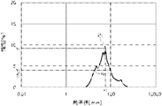
- FIG. 4 is a particle size distribution curve on a volume basis by light scattering particle size measurement of particles containing the urea-based thickener (B) in the grease composition manufactured in Example 1.
- the particle diameter r 1 of the peak P 1 as the maximum frequency y 1 is 0.6 .mu.m
- the half width x 1 of the peak P 1 is 0.6 .mu.m
- the requirements (I) And (II) were satisfied.
- the particle size distribution curve shown in FIG. 5 is a particle size distribution curve on a volume basis based on light scattering particle size measurement of particles containing the urea-based thickener (B) in the grease composition manufactured in Comparative Example 1.
- the particle diameter r 2 of the peak P 2 as the maximum frequency y 2 is 90 [mu] m
- a half-value width x 2 of the peak P 2 is 30 [mu] m
- requirement (I) and ( It does not satisfy II) That is, in the grease composition prepared in Example 1 satisfying the requirements (I) and (II), the aggregation of the urea-based thickener is suppressed even if it is mixed with the antioxidant and the rust inhibitor, and the dispersion is highly dispersed. It can be said that Therefore, it is considered that the wear resistance and the friction reducing effect are improved while maintaining the good oxidation stability.
Abstract
L'invention concerne une composition de graisse contenant une huile de base (A), un épaississant à base d'urée (B), un antioxydant (C) et un antirouille (D), le pic de fréquence maximale dans la courbe de distribution de taille de particule sur une base de volume obtenu par mesure de la taille de particule de diffusion de lumière de particules contenant l'épaississant à base d'urée (B) dans la composition de graisse satisfaisant les exigences (I) et (II). ∙ Exigence (I) : le diamètre de particule au pic de fréquence maximale est inférieur ou égal à 1,0 µm. ∙ Exigence (II) : la demi-largeur du pic est inférieure ou égale à 1,0 µm.
Priority Applications (4)
| Application Number | Priority Date | Filing Date | Title |
|---|---|---|---|
| CN201880050542.6A CN110892047A (zh) | 2017-08-31 | 2018-08-22 | 润滑脂组合物 |
| US16/627,861 US20210095219A1 (en) | 2017-08-31 | 2018-08-22 | Grease composition |
| EP18850947.5A EP3677661A4 (fr) | 2017-08-31 | 2018-08-22 | Composition de graisse |
| JP2019539410A JPWO2019044624A1 (ja) | 2017-08-31 | 2018-08-22 | グリース組成物 |
Applications Claiming Priority (2)
| Application Number | Priority Date | Filing Date | Title |
|---|---|---|---|
| JP2017-167588 | 2017-08-31 | ||
| JP2017167588 | 2017-08-31 |
Publications (1)
| Publication Number | Publication Date |
|---|---|
| WO2019044624A1 true WO2019044624A1 (fr) | 2019-03-07 |
Family
ID=65525356
Family Applications (1)
| Application Number | Title | Priority Date | Filing Date |
|---|---|---|---|
| PCT/JP2018/030988 WO2019044624A1 (fr) | 2017-08-31 | 2018-08-22 | Composition de graisse |
Country Status (5)
| Country | Link |
|---|---|
| US (1) | US20210095219A1 (fr) |
| EP (1) | EP3677661A4 (fr) |
| JP (1) | JPWO2019044624A1 (fr) |
| CN (1) | CN110892047A (fr) |
| WO (1) | WO2019044624A1 (fr) |
Cited By (2)
| Publication number | Priority date | Publication date | Assignee | Title |
|---|---|---|---|---|
| WO2022211119A1 (fr) * | 2021-03-31 | 2022-10-06 | 出光興産株式会社 | Composition de graisse |
| WO2022211117A1 (fr) * | 2021-03-31 | 2022-10-06 | 出光興産株式会社 | Composition de graisse |
Families Citing this family (2)
| Publication number | Priority date | Publication date | Assignee | Title |
|---|---|---|---|---|
| JP7341940B2 (ja) * | 2020-03-31 | 2023-09-11 | 出光興産株式会社 | グリース組成物 |
| CN113372981A (zh) * | 2021-05-19 | 2021-09-10 | 安美科技股份有限公司 | 纤维润滑剂及其制备方法 |
Citations (7)
| Publication number | Priority date | Publication date | Assignee | Title |
|---|---|---|---|---|
| JPS52156274A (en) * | 1976-06-21 | 1977-12-26 | Nippon Oil Co Ltd | Break grease composition |
| JPS61162595A (ja) * | 1985-01-10 | 1986-07-23 | Nippon Oil Co Ltd | グリ−ス組成物 |
| JPH02196894A (ja) * | 1989-01-26 | 1990-08-03 | Sumitomo Wiring Syst Ltd | 自動車用ワイヤーハーネス配線コネクター充填用グリース組成物 |
| JP2007217609A (ja) * | 2006-02-17 | 2007-08-30 | Nsk Ltd | グリース組成物及び軸受 |
| JP2008013624A (ja) | 2006-07-04 | 2008-01-24 | Nsk Ltd | 耐水性グリース組成物及び車両用ハブユニット軸受 |
| WO2014142198A1 (fr) * | 2013-03-14 | 2014-09-18 | 出光興産株式会社 | Composition de graisse pour palier |
| JP2017115109A (ja) * | 2015-12-25 | 2017-06-29 | 出光興産株式会社 | グリース製造装置、及びグリースの製造方法 |
Family Cites Families (7)
| Publication number | Priority date | Publication date | Assignee | Title |
|---|---|---|---|---|
| WO2006078035A1 (fr) * | 2005-01-24 | 2006-07-27 | Nsk Ltd. | Roulement, composition de graisse pour un roulement de moyeu et roulement de moyeu pour des vehicules |
| DE102005014272A1 (de) * | 2005-03-24 | 2006-09-28 | Rhein Chemie Rheinau Gmbh | Mikrogele und Verdickungsmittel enthaltende Zusammensetzungen |
| CN103097504B (zh) * | 2011-08-26 | 2014-06-18 | 日本精工株式会社 | 润滑脂组合物和滚动装置 |
| CN105814178A (zh) * | 2013-12-02 | 2016-07-27 | 捷客斯能源株式会社 | 润滑脂组合物 |
| CN106459803B (zh) * | 2014-05-27 | 2021-05-04 | 出光兴产株式会社 | 脲基润滑脂 |
| EP3255130A4 (fr) * | 2015-02-05 | 2018-08-01 | Idemitsu Kosan Co.,Ltd. | Graisse et procédé de fabrication de graisse |
| JP6691679B2 (ja) * | 2015-04-15 | 2020-05-13 | 株式会社ジェイテクト | グリース組成物および当該グリース組成物が封入された転がり軸受 |
-
2018
- 2018-08-22 JP JP2019539410A patent/JPWO2019044624A1/ja not_active Withdrawn
- 2018-08-22 CN CN201880050542.6A patent/CN110892047A/zh active Pending
- 2018-08-22 EP EP18850947.5A patent/EP3677661A4/fr not_active Withdrawn
- 2018-08-22 US US16/627,861 patent/US20210095219A1/en not_active Abandoned
- 2018-08-22 WO PCT/JP2018/030988 patent/WO2019044624A1/fr unknown
Patent Citations (7)
| Publication number | Priority date | Publication date | Assignee | Title |
|---|---|---|---|---|
| JPS52156274A (en) * | 1976-06-21 | 1977-12-26 | Nippon Oil Co Ltd | Break grease composition |
| JPS61162595A (ja) * | 1985-01-10 | 1986-07-23 | Nippon Oil Co Ltd | グリ−ス組成物 |
| JPH02196894A (ja) * | 1989-01-26 | 1990-08-03 | Sumitomo Wiring Syst Ltd | 自動車用ワイヤーハーネス配線コネクター充填用グリース組成物 |
| JP2007217609A (ja) * | 2006-02-17 | 2007-08-30 | Nsk Ltd | グリース組成物及び軸受 |
| JP2008013624A (ja) | 2006-07-04 | 2008-01-24 | Nsk Ltd | 耐水性グリース組成物及び車両用ハブユニット軸受 |
| WO2014142198A1 (fr) * | 2013-03-14 | 2014-09-18 | 出光興産株式会社 | Composition de graisse pour palier |
| JP2017115109A (ja) * | 2015-12-25 | 2017-06-29 | 出光興産株式会社 | グリース製造装置、及びグリースの製造方法 |
Non-Patent Citations (1)
| Title |
|---|
| See also references of EP3677661A4 * |
Cited By (2)
| Publication number | Priority date | Publication date | Assignee | Title |
|---|---|---|---|---|
| WO2022211119A1 (fr) * | 2021-03-31 | 2022-10-06 | 出光興産株式会社 | Composition de graisse |
| WO2022211117A1 (fr) * | 2021-03-31 | 2022-10-06 | 出光興産株式会社 | Composition de graisse |
Also Published As
| Publication number | Publication date |
|---|---|
| CN110892047A (zh) | 2020-03-17 |
| JPWO2019044624A1 (ja) | 2020-08-13 |
| US20210095219A1 (en) | 2021-04-01 |
| EP3677661A1 (fr) | 2020-07-08 |
| EP3677661A4 (fr) | 2021-05-05 |
Similar Documents
| Publication | Publication Date | Title |
|---|---|---|
| JP7389790B2 (ja) | グリース組成物、該グリース組成物を用いた摺動機構の潤滑方法及び装置 | |
| JP7467410B2 (ja) | グリース組成物 | |
| JP7281416B2 (ja) | グリース組成物 | |
| WO2019044624A1 (fr) | Composition de graisse | |
| CN112639060B (zh) | 等速万向节用润滑脂组合物 | |
| WO2020158907A1 (fr) | Composition de graisse | |
| WO2020179603A1 (fr) | Composition de graisse | |
| WO2021200120A1 (fr) | Composition de graisse | |
| WO2023277044A1 (fr) | Composition de graisse | |
| JP7336411B2 (ja) | グリース組成物 | |
| WO2022211119A1 (fr) | Composition de graisse | |
| WO2022211117A1 (fr) | Composition de graisse | |
| JP2023151693A (ja) | グリース組成物 |
Legal Events
| Date | Code | Title | Description |
|---|---|---|---|
| 121 | Ep: the epo has been informed by wipo that ep was designated in this application |
Ref document number: 18850947 Country of ref document: EP Kind code of ref document: A1 |
|
| ENP | Entry into the national phase |
Ref document number: 2019539410 Country of ref document: JP Kind code of ref document: A |
|
| NENP | Non-entry into the national phase |
Ref country code: DE |
|
| ENP | Entry into the national phase |
Ref document number: 2018850947 Country of ref document: EP Effective date: 20200331 |