WO2019044624A1 - Grease composition - Google Patents
Grease composition Download PDFInfo
- Publication number
- WO2019044624A1 WO2019044624A1 PCT/JP2018/030988 JP2018030988W WO2019044624A1 WO 2019044624 A1 WO2019044624 A1 WO 2019044624A1 JP 2018030988 W JP2018030988 W JP 2018030988W WO 2019044624 A1 WO2019044624 A1 WO 2019044624A1
- Authority
- WO
- WIPO (PCT)
- Prior art keywords
- grease composition
- grease
- urea
- group
- thickener
- Prior art date
Links
Images


Classifications
-
- C—CHEMISTRY; METALLURGY
- C10—PETROLEUM, GAS OR COKE INDUSTRIES; TECHNICAL GASES CONTAINING CARBON MONOXIDE; FUELS; LUBRICANTS; PEAT
- C10M—LUBRICATING COMPOSITIONS; USE OF CHEMICAL SUBSTANCES EITHER ALONE OR AS LUBRICATING INGREDIENTS IN A LUBRICATING COMPOSITION
- C10M115/00—Lubricating compositions characterised by the thickener being a non-macromolecular organic compound other than a carboxylic acid or salt thereof
- C10M115/08—Lubricating compositions characterised by the thickener being a non-macromolecular organic compound other than a carboxylic acid or salt thereof containing nitrogen
-
- C—CHEMISTRY; METALLURGY
- C10—PETROLEUM, GAS OR COKE INDUSTRIES; TECHNICAL GASES CONTAINING CARBON MONOXIDE; FUELS; LUBRICANTS; PEAT
- C10M—LUBRICATING COMPOSITIONS; USE OF CHEMICAL SUBSTANCES EITHER ALONE OR AS LUBRICATING INGREDIENTS IN A LUBRICATING COMPOSITION
- C10M169/00—Lubricating compositions characterised by containing as components a mixture of at least two types of ingredient selected from base-materials, thickeners or additives, covered by the preceding groups, each of these compounds being essential
- C10M169/06—Mixtures of thickeners and additives
-
- C—CHEMISTRY; METALLURGY
- C10—PETROLEUM, GAS OR COKE INDUSTRIES; TECHNICAL GASES CONTAINING CARBON MONOXIDE; FUELS; LUBRICANTS; PEAT
- C10M—LUBRICATING COMPOSITIONS; USE OF CHEMICAL SUBSTANCES EITHER ALONE OR AS LUBRICATING INGREDIENTS IN A LUBRICATING COMPOSITION
- C10M129/00—Lubricating compositions characterised by the additive being an organic non-macromolecular compound containing oxygen
- C10M129/02—Lubricating compositions characterised by the additive being an organic non-macromolecular compound containing oxygen having a carbon chain of less than 30 atoms
- C10M129/68—Esters
- C10M129/76—Esters containing free hydroxy or carboxyl groups
-
- C—CHEMISTRY; METALLURGY
- C10—PETROLEUM, GAS OR COKE INDUSTRIES; TECHNICAL GASES CONTAINING CARBON MONOXIDE; FUELS; LUBRICANTS; PEAT
- C10M—LUBRICATING COMPOSITIONS; USE OF CHEMICAL SUBSTANCES EITHER ALONE OR AS LUBRICATING INGREDIENTS IN A LUBRICATING COMPOSITION
- C10M171/00—Lubricating compositions characterised by purely physical criteria, e.g. containing as base-material, thickener or additive, ingredients which are characterised exclusively by their numerically specified physical properties, i.e. containing ingredients which are physically well-defined but for which the chemical nature is either unspecified or only very vaguely indicated
- C10M171/06—Particles of special shape or size
-
- C—CHEMISTRY; METALLURGY
- C10—PETROLEUM, GAS OR COKE INDUSTRIES; TECHNICAL GASES CONTAINING CARBON MONOXIDE; FUELS; LUBRICANTS; PEAT
- C10M—LUBRICATING COMPOSITIONS; USE OF CHEMICAL SUBSTANCES EITHER ALONE OR AS LUBRICATING INGREDIENTS IN A LUBRICATING COMPOSITION
- C10M2205/00—Organic macromolecular hydrocarbon compounds or fractions, whether or not modified by oxidation as ingredients in lubricant compositions
- C10M2205/02—Organic macromolecular hydrocarbon compounds or fractions, whether or not modified by oxidation as ingredients in lubricant compositions containing acyclic monomers
- C10M2205/028—Organic macromolecular hydrocarbon compounds or fractions, whether or not modified by oxidation as ingredients in lubricant compositions containing acyclic monomers containing aliphatic monomers having more than four carbon atoms
- C10M2205/0285—Organic macromolecular hydrocarbon compounds or fractions, whether or not modified by oxidation as ingredients in lubricant compositions containing acyclic monomers containing aliphatic monomers having more than four carbon atoms used as base material
-
- C—CHEMISTRY; METALLURGY
- C10—PETROLEUM, GAS OR COKE INDUSTRIES; TECHNICAL GASES CONTAINING CARBON MONOXIDE; FUELS; LUBRICANTS; PEAT
- C10M—LUBRICATING COMPOSITIONS; USE OF CHEMICAL SUBSTANCES EITHER ALONE OR AS LUBRICATING INGREDIENTS IN A LUBRICATING COMPOSITION
- C10M2207/00—Organic non-macromolecular hydrocarbon compounds containing hydrogen, carbon and oxygen as ingredients in lubricant compositions
- C10M2207/02—Hydroxy compounds
- C10M2207/023—Hydroxy compounds having hydroxy groups bound to carbon atoms of six-membered aromatic rings
- C10M2207/026—Hydroxy compounds having hydroxy groups bound to carbon atoms of six-membered aromatic rings with tertiary alkyl groups
-
- C—CHEMISTRY; METALLURGY
- C10—PETROLEUM, GAS OR COKE INDUSTRIES; TECHNICAL GASES CONTAINING CARBON MONOXIDE; FUELS; LUBRICANTS; PEAT
- C10M—LUBRICATING COMPOSITIONS; USE OF CHEMICAL SUBSTANCES EITHER ALONE OR AS LUBRICATING INGREDIENTS IN A LUBRICATING COMPOSITION
- C10M2207/00—Organic non-macromolecular hydrocarbon compounds containing hydrogen, carbon and oxygen as ingredients in lubricant compositions
- C10M2207/28—Esters
- C10M2207/287—Partial esters
- C10M2207/289—Partial esters containing free hydroxy groups
-
- C—CHEMISTRY; METALLURGY
- C10—PETROLEUM, GAS OR COKE INDUSTRIES; TECHNICAL GASES CONTAINING CARBON MONOXIDE; FUELS; LUBRICANTS; PEAT
- C10M—LUBRICATING COMPOSITIONS; USE OF CHEMICAL SUBSTANCES EITHER ALONE OR AS LUBRICATING INGREDIENTS IN A LUBRICATING COMPOSITION
- C10M2215/00—Organic non-macromolecular compounds containing nitrogen as ingredients in lubricant compositions
- C10M2215/02—Amines, e.g. polyalkylene polyamines; Quaternary amines
- C10M2215/06—Amines, e.g. polyalkylene polyamines; Quaternary amines having amino groups bound to carbon atoms of six-membered aromatic rings
- C10M2215/064—Di- and triaryl amines
-
- C—CHEMISTRY; METALLURGY
- C10—PETROLEUM, GAS OR COKE INDUSTRIES; TECHNICAL GASES CONTAINING CARBON MONOXIDE; FUELS; LUBRICANTS; PEAT
- C10M—LUBRICATING COMPOSITIONS; USE OF CHEMICAL SUBSTANCES EITHER ALONE OR AS LUBRICATING INGREDIENTS IN A LUBRICATING COMPOSITION
- C10M2215/00—Organic non-macromolecular compounds containing nitrogen as ingredients in lubricant compositions
- C10M2215/10—Amides of carbonic or haloformic acids
- C10M2215/102—Ureas; Semicarbazides; Allophanates
- C10M2215/1026—Ureas; Semicarbazides; Allophanates used as thickening material
-
- C—CHEMISTRY; METALLURGY
- C10—PETROLEUM, GAS OR COKE INDUSTRIES; TECHNICAL GASES CONTAINING CARBON MONOXIDE; FUELS; LUBRICANTS; PEAT
- C10N—INDEXING SCHEME ASSOCIATED WITH SUBCLASS C10M RELATING TO LUBRICATING COMPOSITIONS
- C10N2020/00—Specified physical or chemical properties or characteristics, i.e. function, of component of lubricating compositions
- C10N2020/01—Physico-chemical properties
- C10N2020/02—Viscosity; Viscosity index
-
- C—CHEMISTRY; METALLURGY
- C10—PETROLEUM, GAS OR COKE INDUSTRIES; TECHNICAL GASES CONTAINING CARBON MONOXIDE; FUELS; LUBRICANTS; PEAT
- C10N—INDEXING SCHEME ASSOCIATED WITH SUBCLASS C10M RELATING TO LUBRICATING COMPOSITIONS
- C10N2020/00—Specified physical or chemical properties or characteristics, i.e. function, of component of lubricating compositions
- C10N2020/01—Physico-chemical properties
- C10N2020/055—Particles related characteristics
- C10N2020/06—Particles of special shape or size
-
- C—CHEMISTRY; METALLURGY
- C10—PETROLEUM, GAS OR COKE INDUSTRIES; TECHNICAL GASES CONTAINING CARBON MONOXIDE; FUELS; LUBRICANTS; PEAT
- C10N—INDEXING SCHEME ASSOCIATED WITH SUBCLASS C10M RELATING TO LUBRICATING COMPOSITIONS
- C10N2030/00—Specified physical or chemical properties which is improved by the additive characterising the lubricating composition, e.g. multifunctional additives
- C10N2030/06—Oiliness; Film-strength; Anti-wear; Resistance to extreme pressure
-
- C—CHEMISTRY; METALLURGY
- C10—PETROLEUM, GAS OR COKE INDUSTRIES; TECHNICAL GASES CONTAINING CARBON MONOXIDE; FUELS; LUBRICANTS; PEAT
- C10N—INDEXING SCHEME ASSOCIATED WITH SUBCLASS C10M RELATING TO LUBRICATING COMPOSITIONS
- C10N2030/00—Specified physical or chemical properties which is improved by the additive characterising the lubricating composition, e.g. multifunctional additives
- C10N2030/10—Inhibition of oxidation, e.g. anti-oxidants
-
- C—CHEMISTRY; METALLURGY
- C10—PETROLEUM, GAS OR COKE INDUSTRIES; TECHNICAL GASES CONTAINING CARBON MONOXIDE; FUELS; LUBRICANTS; PEAT
- C10N—INDEXING SCHEME ASSOCIATED WITH SUBCLASS C10M RELATING TO LUBRICATING COMPOSITIONS
- C10N2030/00—Specified physical or chemical properties which is improved by the additive characterising the lubricating composition, e.g. multifunctional additives
- C10N2030/12—Inhibition of corrosion, e.g. anti-rust agents or anti-corrosives
-
- C—CHEMISTRY; METALLURGY
- C10—PETROLEUM, GAS OR COKE INDUSTRIES; TECHNICAL GASES CONTAINING CARBON MONOXIDE; FUELS; LUBRICANTS; PEAT
- C10N—INDEXING SCHEME ASSOCIATED WITH SUBCLASS C10M RELATING TO LUBRICATING COMPOSITIONS
- C10N2040/00—Specified use or application for which the lubricating composition is intended
- C10N2040/02—Bearings
-
- C—CHEMISTRY; METALLURGY
- C10—PETROLEUM, GAS OR COKE INDUSTRIES; TECHNICAL GASES CONTAINING CARBON MONOXIDE; FUELS; LUBRICANTS; PEAT
- C10N—INDEXING SCHEME ASSOCIATED WITH SUBCLASS C10M RELATING TO LUBRICATING COMPOSITIONS
- C10N2040/00—Specified use or application for which the lubricating composition is intended
- C10N2040/04—Oil-bath; Gear-boxes; Automatic transmissions; Traction drives
- C10N2040/046—Oil-bath; Gear-boxes; Automatic transmissions; Traction drives for traction drives
-
- C—CHEMISTRY; METALLURGY
- C10—PETROLEUM, GAS OR COKE INDUSTRIES; TECHNICAL GASES CONTAINING CARBON MONOXIDE; FUELS; LUBRICANTS; PEAT
- C10N—INDEXING SCHEME ASSOCIATED WITH SUBCLASS C10M RELATING TO LUBRICATING COMPOSITIONS
- C10N2050/00—Form in which the lubricant is applied to the material being lubricated
- C10N2050/10—Semi-solids; greasy
-
- C—CHEMISTRY; METALLURGY
- C10—PETROLEUM, GAS OR COKE INDUSTRIES; TECHNICAL GASES CONTAINING CARBON MONOXIDE; FUELS; LUBRICANTS; PEAT
- C10N—INDEXING SCHEME ASSOCIATED WITH SUBCLASS C10M RELATING TO LUBRICATING COMPOSITIONS
- C10N2070/00—Specific manufacturing methods for lubricant compositions
Definitions
- the present invention relates to grease compositions.
- Grease is widely used to lubricate various sliding parts of automobiles and various industrial machines because sealing is easier than lubricating oil, and the size and weight of applied machines can be reduced. It is done.
- Grease is mainly composed of base oil and thickener. The solid nature of the grease is conferred by the thickener and the performance of the grease depends largely on the thickener used. For example, a urea-based grease using a urea-based thickener has a feature that the lubricating life at high temperature is long and the oxidation stability, heat resistance and water resistance are excellent.
- Patent Document 1 discloses, as a grease composition used for a hub unit bearing for a vehicle incorporated in an automobile, a railway, etc., a base oil comprising at least one of mineral oil and synthetic oil, aromatic urea as a thickener, There is disclosed a water resistant grease composition prepared by blending three specific antirust agents.
- Urea-based greases are required to further improve wear resistance and friction reduction characteristics.
- a grease composition is prepared by blending an antioxidant and a rust inhibitor with a urea-based grease in order to improve the oxidation stability, the grease composition It has been found that the wear resistance and the friction characteristics may be deteriorated.
- blended antioxidant and a rust preventive agent is not performed.
- the present invention has been made to solve the above-mentioned problems, and it is an object of the present invention to provide a urea-based grease composition excellent in oxidation stability, abrasion resistance and friction characteristics.
- the present inventors focused attention on the particle size distribution of particles containing a urea-based thickener in the grease composition, in a grease composition containing a base oil, a urea-based thickener, an antioxidant, and a rust inhibitor. did. And, it is found that the grease composition adjusted so that the particle diameter and the half width at the peak which is the maximum frequency of the particle diameter distribution falls within a predetermined range can solve the above-mentioned problems, and the present invention is completed.
- a grease composition comprising a base oil (A), a urea thickener (B), an antioxidant (C), and a rust inhibitor (D),
- a grease composition comprising a base oil (A), a urea thickener (B), an antioxidant (C), and a rust inhibitor (D)
- the peak having the largest frequency is the following requirements (I) and (II) Meet the grease composition.
- Requirement (II) The half width of the peak is 1.0 ⁇ m or less.
- the grease composition of the present invention has excellent oxidative stability, abrasion resistance and friction properties.
- FIG. 1 is a cross-sectional schematic view of a grease-producing apparatus that can be used in one aspect of the present invention. It is a cross-sectional schematic diagram of the horizontal direction of the stirring part of the grease manufacturing apparatus of FIG. It is a cross-sectional schematic diagram of the grease manufacturing apparatus used by the comparative example 1.
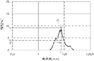
- FIG. It is a particle size distribution curve on a volume basis by light scattering particle size measurement of particles containing a urea-based thickener (B) in the grease composition manufactured in Example 1. It is a particle size distribution curve on a volume basis by light scattering particle size measurement of particles containing a urea-based thickener (B) in the grease composition manufactured in Comparative Example 1.
- the grease composition of the present invention contains a base oil (A), a urea thickener (B), an antioxidant (C), and a rust inhibitor (D).
- the base oil (A), the urea thickener (B), the antioxidant (C), and the rust inhibitor (D) are respectively component (A), component (B), component (C) And component (D).
- the grease composition of one embodiment of the present invention may contain additives other than the components (A) to (D) within the range not impairing the effects of the present invention.
- the total content of the components (A), (B), (C), and (D) described above is based on the total amount (100% by mass) of the grease composition.
- the content is preferably 60 to 100% by mass, more preferably 70 to 100% by mass, still more preferably 80 to 100% by mass, and still more preferably 90 to 100% by mass.
- the peak having the largest frequency is the following requirement (I) And (II) are satisfied.
- a grease composition containing an additive such as an antioxidant (C) and a rust inhibitor (D) together with a base oil (A) and a urea thickener (B) It can be said that it is a parameter indicating the state of aggregation of the urea thickener (B).
- grain containing a urea-type thickener (B) used as a measuring object here refers to the particle which a urea-type thickener (B) aggregates, but a urea-type thickener (B)
- additives such as an antioxidant (C) and an antirust agent (D) are also included which are aggregated and incorporated.
- an aggregate that contains only the additive such as the antioxidant (C) or the rust inhibitor (D) but does not contain the urea thickener (B) is the above-mentioned "urea thickener (B)".
- urea thickener (B) are excluded from “particles containing”.
- “excluded” means that an aggregate consisting only of an additive such as an antioxidant (C) or a rust inhibitor (D) is compared to “a particle containing a urea thickener (B)”. Since it is very small, it is hardly detected in light scattering particle size measurement, which means that even if it is detected, it is at a negligible level.
- the present inventors measured the light scattering particle diameter of the particles containing the urea-based thickener (B) in the grease composition which also contains the additive such as the antioxidant (C) and the rust inhibitor (D). We focused on the peak that is the maximum frequency of the particle size distribution curve on a volume basis.
- Requirement (I) stipulates that the particle diameter at which the peak frequency is maximum is 1.0 ⁇ m or less.
- the said particle diameter can be said to be a parameter
- the particle diameter as the maximum frequency of the peak defined in the requirement (I) is 1.0 ⁇ m or less, preferably 0.9 ⁇ m or less, more preferably 0.8 ⁇ m or less, still more preferably It is 0.7 ⁇ m or less, more preferably 0.6 ⁇ m or less, and usually 0.01 ⁇ m or more.
- the particle diameter used as the maximum frequency of the said peak means the value of the particle diameter in the peak of the said peak.
- requirement (II) stipulates that the half width of the peak is 1.0 ⁇ m or less.
- the said half value width can be said to be an index showing the distribution of particles containing a urea thickener (B) larger than the particle diameter which is the maximum frequency specified in the requirement (I).
- the half value width of the peak defined in the requirement (II) means the particle size at 50% of the maximum frequency of the requirement (I) in the particle size distribution curve on the volume basis by light scattering particle size measurement of the particles. Represents the spread width. That is, it can be said that, when the half width is more than 1.0 ⁇ m, a large number of micellar particles of the urea thickener (B) larger than the particle diameter specified in the requirement (I) are dispersed.
- the half width of the peak defined in the requirement (II) is 1.0 ⁇ m or less, preferably 0.9 ⁇ m or less, more preferably 0.8 ⁇ m or less, still more preferably 0.7 ⁇ m or less Still more preferably, it is 0.6 ⁇ m or less, and usually 0.01 ⁇ m or more.
- the values defined by the above requirements (I) and (II) are values calculated from the particle size distribution curve measured by the method of the examples described later.
- the values specified in requirements (I) and (II) are the types, properties and contents of each component contained in the grease composition, the production conditions of the urea thickener (B), the antioxidant (C ) And the antirust agent (D) can be adjusted by appropriately selecting the blending conditions of the additives.
- the values defined by the requirements (I) and (II) are relatively largely influenced by the production conditions of the urea thickener (B) and the compounding conditions of the additives.
- the details of each component contained in the grease composition of the present invention will be described, focusing on the specific means for adjusting the values defined in the requirements (I) and (II).
- the base oil (A) contained in the grease composition of the present invention may be at least one selected from mineral oil and synthetic oil.
- mineral oils include paraffinic crude oils, medium-based crude oils, distillates obtained by atmospheric distillation or vacuum distillation of naphthenic crude oils, and refined products obtained by refining these distillates according to a conventional method Oil is mentioned.
- the purification method include solvent dewaxing treatment, hydroisomerization treatment, hydrofinishing treatment, clay treatment and the like.
- Examples of synthetic oils include hydrocarbon oils, aromatic oils, ester oils, ether oils, synthetic oils obtained by isomerizing a wax (GTL wax) produced by the Fischer-Tropsch method, etc. Can be mentioned.
- Examples of hydrocarbon oils include normal paraffins, isoparaffins, polybutenes, polyisobutylenes, 1-decene oligomers, poly- ⁇ -olefins (PAO) such as 1-decene and ethylene co-oligomer, and hydrides of these. .
- aromatic oils examples include alkylbenzenes such as monoalkylbenzenes and dialkylbenzenes; and alkylnaphthalenes such as monoalkylnaphthalenes, dialkylnaphthalenes and polyalkylnaphthalenes.
- ester-based oils include di-ester-based oils such as dibutyl sebacate, di-2-ethylhexyl sebacate, dioctyl adipate, diisodecyl adipate, ditridecyl adipate, ditridecyl adipate, ditridecyl glutarate, methyl acetyl ricinolate; Aromatic ester oils such as decyl trimellitate and tetraoctyl pyromelitate; Polyol esters such as trimethylol propane caprylate, trimethylol propane berargonate, pentaerythritol 2-ethylhexanoate, and pentaerythritol belargonate Oil-based oils; complex ester-based oils such as oligoesters of polyhydric alcohols and mixed fatty acids of dibasic acids and monobasic acids; and the like.
- di-ester-based oils such as di
- ether oils include polyglycols such as polyethylene glycol, polypropylene glycol, polyethylene glycol monoether and polypropylene glycol monoether; monoalkyl triphenyl ether, alkyl diphenyl ether, dialkyl diphenyl ether, pentaphenyl ether, tetraphenyl ether, monoalkyl And phenyl ether-based oils such as tetraphenyl ether and dialkyl tetraphenyl ether; and the like.
- polyglycols such as polyethylene glycol, polypropylene glycol, polyethylene glycol monoether and polypropylene glycol monoether
- monoalkyl triphenyl ether alkyl diphenyl ether, dialkyl diphenyl ether, pentaphenyl ether, tetraphenyl ether, monoalkyl
- phenyl ether-based oils such as tetraphenyl ether and dialkyl tetraphen
- the kinematic viscosity at 40 ° C. of the base oil (A) used in one embodiment of the present invention is preferably 10 to 130 mm 2 / s, more preferably 15 to 110 mm 2 / s, still more preferably 20 to 100 mm 2 / s. is there.
- the base oil (A) used in one aspect of the present invention may be a mixed base oil having a kinematic viscosity adjusted to the above range by combining a high viscosity base oil and a low viscosity base oil.
- the viscosity index of the base oil (A) used in one aspect of the present invention is preferably 60 or more, more preferably 70 or more, and still more preferably 80 or more.
- the kinematic viscosity and the viscosity index mean values measured according to JIS K 2283: 2003.
- the content of the base oil (A) is preferably 50% by mass or more, more preferably 55% by mass or more, based on the total amount (100% by mass) of the grease composition. More preferably, it is 60% by mass or more, more preferably 65% by mass or more, preferably 98.5% by mass or less, more preferably 97% by mass or less, still more preferably 95% by mass or less, still more preferably It is 93 mass% or less.
- the urea-based thickener (B) contained in the grease composition of the present invention may be a compound having a urea bond, but a diurea having two urea bonds is preferable, and is represented by the following general formula (b1) Compounds are more preferred.
- the urea-based thickener (B) used in one aspect of the present invention may consist of one type, or a mixture of two or more types.
- R 1 and R 2 each independently represent a monovalent hydrocarbon group having 6 to 24 carbon atoms, and R 1 and R 2 may be identical to or different from each other It may be R 3 represents a divalent aromatic hydrocarbon group having 6 to 18 carbon atoms.
- the carbon number of the monovalent hydrocarbon group which can be selected as R 1 and R 2 in the general formula (b1) is 6 to 24, preferably 6 to 20, more preferably 6 to 18. .
- a saturated or unsaturated monovalent chain hydrocarbon group a saturated or unsaturated monovalent alicyclic hydrocarbon group, 1 Aromatic aromatic hydrocarbon groups are preferred, and saturated or unsaturated monovalent chain hydrocarbon groups are preferred.
- the monovalent saturated chain hydrocarbon group includes a linear or branched alkyl group having 6 to 24 carbon atoms, and specific examples thereof include hexyl group, heptyl group, octyl group, nonyl group and decyl group. Examples include undecyl group, dodecyl group, tridecyl group, tetradecyl group, pentadecyl group, hexadecyl group, heptadecyl group, octadecyl group, octadecenyl group, nonadecyl group, icosyl group and the like.
- the monovalent unsaturated chain hydrocarbon group includes a linear or branched alkenyl group having 6 to 24 carbon atoms, and specific examples thereof include a hexenyl group, a heptenyl group, an octenyl group, a nonenyl group and a decenyl group. And dodecenyl group, tridecenyl group, tetradecenyl group, pentadecenyl group, hexadecenyl group, octadecenyl group, nonadecenyl group, icosenyl group, oleyl group, geranyl group, farnesyl group, linoleyl group and the like.
- the monovalent saturated chain hydrocarbon group and the monovalent unsaturated chain hydrocarbon group may be linear or branched.
- Examples of monovalent saturated alicyclic hydrocarbon groups include cycloalkyl groups such as cyclohexyl, cycloheptyl, cyclooctyl and cyclononyl; methylcyclohexyl, dimethylcyclohexyl, ethylcyclohexyl and diethylcyclohexyl
- a cycloalkyl group substituted by an alkyl group having 1 to 6 carbon atoms such as propylcyclohexyl, isopropylcyclohexyl, 1-methyl-propylcyclohexyl, butylcyclohexyl, pentylcyclohexyl, pentyl-methylcyclohexyl, hexylcyclohexyl and the like (Preferably, a cyclohexyl group substituted by an alkyl group having 1 to 6 carbon atoms); and the like.
- Examples of the monovalent unsaturated alicyclic hydrocarbon group include cycloalkenyl groups such as cyclohexenyl group, cycloheptenyl group and cyclooctenyl group; methylcyclohexenyl group, dimethylcyclohexenyl group, ethylcyclohexenyl group, diethylcyclohexenyl group And a cycloalkenyl group substituted with an alkyl group having 1 to 6 carbon atoms such as a propyl cyclohexenyl group (preferably, a cyclohexenyl group substituted with an alkyl group having 1 to 6 carbon atoms); and the like.
- cycloalkenyl groups such as cyclohexenyl group, cycloheptenyl group and cyclooctenyl group
- methylcyclohexenyl group dimethylcyclohexenyl group, ethylcyclohe
- monovalent aromatic hydrocarbon group for example, phenyl group, biphenyl group, terphenyl group, naphthyl group, diphenylmethyl group, diphenylethyl group, diphenylpropyl group, methylphenyl group, dimethylphenyl group, ethylphenyl group, A propylphenyl group etc. are mentioned.
- the carbon number of the divalent aromatic hydrocarbon group which can be selected as R 3 in the general formula (b1) is 6 to 18, preferably 6 to 15, and more preferably 6 to 13.
- Examples of the divalent aromatic hydrocarbon group which can be selected as R 3 include phenylene group, diphenylmethylene group, diphenylethylene group, diphenylpropylene group, methylphenylene group, dimethylphenylene group, ethylphenylene group and the like. Among these, a phenylene group, a diphenyl methylene group, a diphenyl ethylene group, or a diphenyl propylene group is preferable, and a diphenyl methylene group is more preferable.
- the content of component (B) is preferably 1 to 40% by mass, more preferably 2 to 30% by mass, based on the total amount (100% by mass) of the grease composition. More preferably, it is 4 to 25% by mass, and still more preferably 6 to 20% by mass. If the content of the component (B) is 1% by mass or more, the worked penetration of the obtained grease composition can be easily adjusted to an appropriate range. On the other hand, if the content of the component (B) is 40% by mass or less, the obtained grease composition does not become too hard and may be generated by poor lubrication, in the lubricated portions such as bearings and sliding portions and joints of the device. It is possible to suppress negative effects such as burn-in to members.
- the urea thickener (B) can be usually obtained by reacting an isocyanate compound with a monoamine.
- the reaction is preferably performed by adding a solution ⁇ in which a monoamine is dissolved in a base oil (A) to a heated solution ⁇ obtained by dissolving an isocyanate compound in the above-mentioned base oil (A).
- a group corresponding to the divalent aromatic hydrocarbon group represented by R 3 in the general formula (b1) can be used.
- the desired urea-based thickener (B) is obtained by the method described above using a diisocyanate having one or more amines and using an amine having a group corresponding to the monovalent hydrocarbon group represented by R 1 and R 2 as a monoamine. It can be synthesized.
- the components are prepared using a grease manufacturing apparatus as shown in the following [1] It is preferred to produce (B).
- a container body having an introduction part into which a grease raw material is introduced, and a discharge part which discharges grease to the outside
- the rotor has an axis of rotation in the axial direction of the inner circumference of the container body, and a rotor rotatably provided inside the container body,
- the rotor is (I) irregularities are alternately provided along the surface of the rotor, and the irregularities are inclined with respect to the rotation axis, (Ii)
- a grease manufacturing apparatus comprising a first uneven portion having a feeding ability from the introduction portion toward the discharge portion.
- the prescription described as "preferred" of the following description is a grease so that requirements (I) and (II) may be satisfied unless there is particular notice.
- This is an embodiment from the viewpoint of dispersing the urea thickener (B) in the composition.
- FIG. 1 is a schematic cross-sectional view of the grease production apparatus of the above [1], which can be used in one aspect of the present invention.
- the grease manufacturing apparatus 1 shown in FIG. 1 has a container body 2 for introducing grease raw material inside, and a rotating shaft 12 on the central axis of the inner periphery of the container body 2 and rotates around the rotating shaft 12 as a central axis. And a child 3.
- the rotor 3 rotates at a high speed with the rotation shaft 12 as a central axis, and applies high shear force to the grease raw material inside the container body 2. Thereby, the grease containing the urea-based thickener (B) is manufactured.
- FIG. 1 is a schematic cross-sectional view of the grease production apparatus of the above [1], which can be used in one aspect of the present invention.
- the grease manufacturing apparatus 1 shown in FIG. 1 has a container body 2 for introducing grease raw material inside, and a rotating shaft 12 on the central axis of the inner periphery of
- the container body 2 is partitioned from the top into the introduction portion 4, the retention portion 5, the first inner circumferential surface 6, the second inner circumferential surface 7, and the discharging portion 8.
- the container body 2 preferably has a frusto-conical inner circumferential surface whose inner diameter gradually increases in the direction from the introduction portion 4 to the discharge portion 8.
- the introducing unit 4 which is one end of the container body 2 includes a plurality of solution introducing pipes 4A and 4B for introducing the grease material from the outside of the container body 2.
- the retention portion 5 is a space which is disposed in the lower part of the introduction portion 4 and temporarily retains the grease material introduced from the introduction portion 4.
- the grease adhering to the inner peripheral surface of the retention part 5 forms a large dam, so it is conveyed to the downstream first inner peripheral surface 6 in as short time as possible. It is preferable to do. More preferably, it is preferable that the sheet is directly transported to the first inner circumferential surface 6 without passing through the retaining portion 5.
- the first inner circumferential surface 6 is disposed at a lower portion adjacent to the retaining portion 5, and the second inner circumferential surface 7 is disposed at a lower portion adjacent to the first inner circumferential surface 6.
- the peripheral surface 7 function as a high shear part which applies a high shear force to the grease raw material or grease.
- the discharge part 8 which becomes the other end of the container main body 2 is a part which discharges the grease stirred by the 1st inner skin 6 and the 2nd inner skin 7, and is provided with discharge mouth 11 which discharges grease.
- the discharge port 11 is formed in the horizontal direction orthogonal to the rotation axis 12. Thereby, the grease is discharged from the discharge port 11 in the horizontal direction.
- the rotor 3 is rotatably provided with the central axis of the frusto-conical inner peripheral surface of the container body 2 as the rotation axis 12, and when the container body 2 is viewed from the top to the bottom as shown in FIG. Rotate counterclockwise.
- the rotor 3 has an outer peripheral surface that expands according to the expansion of the inner diameter of the truncated cone of the container body 2, and the outer peripheral surface of the rotor 3 and the inner peripheral surface of the truncated cone of the container body 2 have a constant distance Is maintained.
- a first uneven portion 13 of the rotor in which the unevenness is alternately provided along the surface of the rotor 3 is provided on an outer peripheral surface of the rotor 3.
- the first uneven portion 13 of the rotor is inclined relative to the rotation shaft 12 of the rotor 3 in the direction from the introduction portion 4 to the discharge portion 8 and has a feeding ability from the introduction portion 4 to the discharge portion 8 direction. That is, when the rotor 3 rotates in the direction shown in FIG. 1, the first uneven portion 13 of the rotor is inclined in the direction of pushing the solution downstream.
- the difference in level between the recess 13A and the protrusion 13B of the first uneven portion 13 of the rotor is preferably 0.3 to 30, and more preferably 0.5. It is preferably -15, more preferably 2-7.
- the number of convex portions 13B of the first uneven portion 13 of the rotor in the circumferential direction is preferably 2 to 1000, more preferably 6 to 500, and still more preferably 12 to 200.
- the ratio of the width of the convex portion 13B of the first concavo-convex portion 13 of the rotor to the width of the concave portion 13A is preferably 0 It is preferably from 0.1 to 100, more preferably from 0.1 to 10, still more preferably from 0.5 to 2.
- the inclination angle of the first uneven portion 13 of the rotor with respect to the rotation axis 12 is preferably 2 to 85 degrees, more preferably 3 to 45 degrees, and still more preferably 5 to 20 degrees.
- the first inner circumferential surface 6 of the container body 2 is preferably provided with a first uneven portion 9 in which a plurality of concavities and convexities are formed along the inner circumferential surface.
- corrugated part 9 by the side of a container inclines in the reverse direction with the 1st uneven
- the stirring ability and the discharging ability are further enhanced by the first uneven portion 9 having the plurality of uneven portions provided on the first inner peripheral surface 6 of the container body 2.
- the depth of the unevenness of the first uneven portion 9 on the container side is preferably 0.2 to 30, more preferably 0.5 to 15, and still more preferably 1 to 5 when the container inner diameter (diameter) is 100. is there.
- the number of unevenness of the first uneven portion 9 on the container side is preferably 2 to 1000, more preferably 6 to 500, and still more preferably 12 to 200.
- the ratio (width of recess / width of protrusion) of the width of the recess and the recess of the first uneven portion 9 on the container side to the width of the protrusion between the grooves is preferably 0.01 to 100, and more preferably 0. 1 to 10, more preferably 0.5 to 2 or less.
- the inclination angle of the unevenness of the first uneven portion 9 on the container side with respect to the rotation axis 12 is preferably 2 to 85 degrees, more preferably 3 to 45 degrees, still more preferably 5 to 20 degrees.
- the second concavo-convex portion 14 of the rotor is inclined with respect to the rotation shaft 12 of the rotor 3 and has a feed restraining ability to push back the solution to the upstream side from the introduction part 4 toward the discharge part 8.
- the step of the second uneven portion 14 of the rotor is preferably 0.3 to 30, more preferably 0.5 to 15, and still more preferably 2 to 7, where the diameter of the recess on the outer peripheral surface of the rotor 3 is 100. It is.
- the number of convex portions of the second uneven portion 14 of the rotor in the circumferential direction is preferably 2 to 1000, more preferably 6 to 500, and still more preferably 12 to 200.
- the ratio of the width of the convex portion of the second concavo-convex portion 14 of the rotor to the width of the concave portion [width of convex portion / width of concave portion] in a cross section orthogonal to the rotation axis of the rotor 3 is preferably 0.01 to The ratio is preferably 100, more preferably 0.1 to 10, and still more preferably 0.5 to 2.
- the inclination angle of the second concavo-convex portion 14 of the rotor with respect to the rotation axis 12 is preferably 2 to 85 degrees, more preferably 3 to 45 degrees, and still more preferably 5 to 20 degrees.
- the second inner circumferential surface 7 of the container body 2 be provided with a second uneven portion 10 having a plurality of uneven portions formed adjacent to the lower portion of the uneven portion in the first uneven portion 9 on the container side .
- a plurality of concavities and convexities on the container side second concavo-convex portion 10 are formed on the inner peripheral surface of the container main body 2, and each concavities and convexities are inclined in the opposite direction to the inclination direction of the second concavo-convex portion 14 of the rotor. Is preferred.
- the plurality of concavities and convexities of the second concavo-convex portion 10 on the container side be inclined in the direction of pushing the solution back when the rotary shaft 12 of the rotor 3 rotates in the direction shown in FIG. .
- the stirring ability is further enhanced by the unevenness of the second uneven portion 10 provided on the second inner circumferential surface 7 of the container body 2.
- the second inner peripheral surface 7 of the container body can function as a high shear portion that applies a high shear force to the grease raw material or grease.
- the depth of the concave portion of the second concavo-convex portion 10 on the container side is preferably 0.2 to 30, more preferably 0.5 to 15, and still more preferably 1 to 5 when the container inner diameter (diameter) is 100. is there.
- the number of concave portions of the second uneven portion 10 on the container side is preferably 2 to 1000, more preferably 6 to 500, and still more preferably 12 to 200.
- the ratio of the width of the convex portion of the concave-convex portion of the second concavo-convex portion 10 on the container side to the width of the concave portion in the cross section orthogonal to the rotation axis 12 of the rotor 3 [width of convex portion / width of concave portion] is preferably 0 .01 to 100, more preferably 0.1 to 10, still more preferably 0.5 to 2 or less.
- the inclination angle of the second uneven portion 10 on the container side with respect to the rotation axis 12 is preferably 2 to 85 degrees, more preferably 3 to 45 degrees, and still more preferably 5 to 20 degrees.
- the ratio [the length of the first uneven portion / the length of the second uneven portion] of the length of the first uneven portion 9 on the container side to the length of the second uneven portion 10 on the container side is preferably 2/1 to It is 20/1.
- FIG. 2 is a horizontal sectional view of the first uneven portion 9 on the container side of the grease manufacturing apparatus 1.
- a plurality of scrapers 15 are provided in the first concavo-convex portion 13 shown in FIG. 2 in which the tip projects to the inner peripheral surface side of the container main body 2 more than the tip in the projection direction of the convex portion 13B of the first concavo-convex portion 13 .
- a plurality of scrapers in which the tip end of the convex portion protrudes to the inner peripheral surface side of the container main body 2 as well as the first uneven portion 13 are provided in the second uneven portion 14.
- the scraper 15 scrapes off the grease adhering to the inner circumferential surface of the first uneven portion 9 on the container side and the second uneven portion 10 on the container side.
- the amount of protrusion of the tip of the scraper 15 is the ratio of the radius (R2) of the tip of the scraper 15 to the radius (R1) of the tip of the protrusion 13B with respect to the amount of protrusion of the protrusion 13B of the first uneven portion 13 of the rotor. It is preferable that [R2 / R1] is more than 1.005 and less than 2.0.
- the number of scrapers 15 is preferably 2 to 500, more preferably 2 to 50, and still more preferably 2 to 10.
- the scraper 15 is provided in the grease manufacturing apparatus 1 shown in FIG. 2, it may not be provided and may be provided intermittently.
- the solution ⁇ and the solution ⁇ which are the grease raw materials described above, are introduced into the solution introducing pipe 4A of the introducing portion 4 of the container main body 2 , 4B, and rotating the rotor 3 at a high speed, a grease containing a urea-based thickener (B) can be produced.
- a grease composition so as to satisfy the above requirements (I) and (II)
- the urea thickener (B) can be dispersed therein.
- the shear rate given to the grease raw material is preferably 10 2 s -1 or more, more preferably 10 3 s -1 or more, and further preferably 10 4 s -1 or more. , Usually less than 10 7 s -1 .
- the ratio (Max / Min) of the maximum shear rate (Max) to the minimum shear rate (Min) in shear at high speed rotation of the rotor 3 is preferably 100 or less, more preferably 50 or less, still more preferably It is 10 or less.
- the highest shear rate (Max) is the highest shear rate applied to the mixture
- the lowest shear rate (Min) is the lowest shear rate applied to the mixture
- ⁇ Maximum shear rate (Max) (linear velocity of the tip of the convex portion 13B of the first concavo-convex portion 13 of the rotor) / (the tip of the convex portion 13B of the first concavo-convex portion 13 of the rotor and the container side of the first concavo-convex portion 6 Gap A1 of the convex portion of the first uneven portion 9 of
- Minimum shear rate (Min) (linear velocity of the recess 13A of the first uneven portion 13 of the rotor) / (first recess and recess of the first uneven portion 13 of the rotor and the container side of the first uneven portion 6 Gap A2 of the recess of the portion 9)
- the gaps A1 and A2 are as shown in FIG.
- the grease manufacturing apparatus 1 Since the grease manufacturing apparatus 1 is provided with the scraper 15, the grease adhering to the inner peripheral surface of the container main body 2 can be scraped off, so that generation of lumps during kneading can be prevented, and urea system A grease in which the thickener (B) is highly dispersed can be continuously produced in a short time.
- the scraper 15 scrapes off the adhering grease, the stagnant grease can be prevented from becoming a resistance to the rotation of the rotor 3, so that the rotational torque of the rotor 3 can be reduced.
- the power consumption of the source can be reduced and efficient continuous production of grease can be achieved.
- the inner peripheral surface of the container body 2 is in the form of a truncated cone whose internal diameter increases as it goes from the introduction part 4 to the discharge part 8, so centrifugal force has the effect of discharging grease or grease raw material in the downstream direction.
- the rotational torque of the element 3 can be reduced to perform continuous production of grease.
- the first uneven portion 13 of the rotor is provided on the outer peripheral surface of the rotor 3, and the first uneven portion 13 of the rotor is inclined with respect to the rotation shaft 12 of the rotor 3.
- the second uneven portion 14 of the rotor is inclined with respect to the rotation shaft 12 of the rotor 3 and has the ability to suppress the feed from the introduction portion 4 to the discharge portion 8.
- a high shear force can be imparted, and the urea thickener (B) can be dispersed in the grease composition so as to satisfy the above requirements (I) and (II) even after the additive is blended. .
- the first concavo-convex portion 9 on the container side is formed on the first inner circumferential surface 6 of the container main body, and the first concavo-convex portion 13 of the rotor is inclined in the opposite direction.
- the urea thickener (B) can be dispersed in the grease composition.
- the container side second concavo-convex portion 10 is provided on the second inner circumferential surface 7 of the container body, and the second concavo-convex portion 14 of the rotor is provided on the outer circumferential surface of the rotor 3. Since it can prevent flowing out from the 1st inner skin 6 of a container main body above, high shear force is given to a solution, grease raw material is highly dispersed, and the above-mentioned requirements (I) and ( The urea thickener (B) can be dispersed in the grease composition so as to satisfy II).
- the antioxidant (C) contained in the grease composition of the present invention may be any compound capable of imparting the antioxidant performance, but from the amine antioxidant (C1) and the phenolic antioxidant (C2) It is preferable to include one or more selected.
- the antioxidant (C) used in one aspect of the present invention may be used alone or in combination of two or more.
- the amine antioxidant (C1) may be a compound having an amino group, but diphenylamine compounds and naphthylamine compounds are preferable.
- diphenylamine compound include monoalkyldiphenylamine compounds having one alkyl group having 1 to 30 carbon atoms (preferably 4 to 30, more preferably 8 to 30) such as monooctyl diphenylamine and monononyl diphenylamine; 4,4'-Dibutyldiphenylamine, 4,4'-Dipentyldiphenylamine, 4,4'-Dihexyldiphenylamine, 4,4'-Diheptyldiphenylamine, 4,4'-Dioctyldiphenylamine, 4,4'-Dinonyldiphenylamine, etc.
- Polyalkyl diphenylamine compounds having three or more alkyl groups having 1 to 30 (preferably 4 to 30, more preferably 8 to 30) carbon atoms such as phenylamine; 4,4'-bis ( ⁇ , ⁇ -dimethylbenzyl) Diphenylamine etc. are mentioned.
- naphthylamine compound for example, 1-naphthylamine, phenyl-1-naphthylamine, butylphenyl-1-naphthylamine, pentylphenyl-1-naphthylamine, hexylphenyl-1-naphthylamine, heptylphenyl-1-naphthylamine, octylphenyl-1 And -naphthylamine, nonylphenyl-1-naphthylamine, decylphenyl-1-naphthylamine, dodecylphenyl-1-naphthylamine and the like.
- diphenylamine compounds compounds represented by the following general formula (c1-1) are preferable. Further, among the naphthylamine compounds, a compound represented by the following general formula (c1-2) or a compound represented by the following general formula (c1-3) is preferable.
- R 11 to R 18 each independently have 1 to 20 carbon atoms (preferably 4 to 18, more preferably 6 to 6). 16, more preferably 8 to 14) alkyl group.
- alkyl group include the same as the alkyl group having 1 to 20 carbon atoms among the alkyl groups which may be possessed by the above-mentioned alkylbenzene (B).
- n1, n2, n3 and n6 are each independently an integer of 0 to 5, preferably an integer of 0 to 3, more preferably an integer of 0 to 1, and still more preferably 1.
- m4 and m7 are each independently an integer of 0 to 3, preferably an integer of 0 to 1, more preferably 0.
- p5 and p8 are each independently an integer of 0 to 4, preferably an integer of 0 to 2, more preferably an integer of 0 to 1, further preferably 0.
- phenolic antioxidant (C2) examples include 2,6-di-t-butyl-4-methylphenol, 2,6-di-t-butyl-4-ethylphenol, 2,4,6-triphenol -T-Butylphenol, 2,6-di-t-butyl-4-hydroxymethylphenol, 2,6-di-t-butylphenol, 2,4-dimethyl-6-t-butylphenol, 2,6-di-t -Butyl-4- (N, N-dimethylaminomethyl) phenol, 2,6-di-t-amyl-4-methylphenol, n-octadecyl-3- (3,5-di-t-butyl-4-) Monocyclic phenol compounds such as hydroxyphenyl) propionate, 4,4′-methylenebis (2,6-di-t-butylphenol), 4,4′-isopropylidenebis (2,6-di-t-butylpheno ), 2,2'-methylenebis (4
- the phenolic antioxidant (C2) may be any compound having a phenolic structure, and may be a monocyclic phenolic compound or a polycyclic phenolic compound.
- monocyclic phenol compounds include 2,6-di-t-butyl-4-methylphenol, 2,6-di-t-butyl-4-ethylphenol, 2,4,6-tri-t- Butylphenol, 2,6-di-tert-butyl-4-hydroxymethylphenol, 2,6-di-tert-butylphenol, 2,4-dimethyl-6-tert-butylphenol, 2,6-di-tert-butyl- 4- (N, N-Dimethylaminomethyl) phenol, 2,6-di-t-amyl-4-methylphenol, Benzenepropanoic acid 3,5-bis (1,1-dimethylethyl) -4-hydroxyalkyl ester Etc.
- polycyclic phenolic compounds examples include 4,4′-methylenebis (2,6-di-t-butylphenol), 4,4′-isopropylidenebis (2,6-di-t-butylphenol), 2, 2'-Methylene bis (4-methyl-6-tert-butylphenol), 4,4'-bis (2,6-di-tert-butylphenol), 4,4'-bis (2-methyl-6-tert-butylphenol) And 2,2'-methylenebis (4-ethyl-6-t-butylphenol), 4,4'-butylidenebis (3-methyl-6-t-butylphenol) and the like.
- the content of the component (C) is preferably 0.01 to 15% by mass, more preferably 0.05 based on the total amount (100% by mass) of the grease composition.
- the content is about 10% by mass, more preferably 0.10 to 7% by mass, and still more preferably 0.50 to 4% by mass.
- the antirust agent (D) contained in the grease composition of the present invention may be any compound capable of imparting antirust performance, such as zinc stearate, carboxylic acid antirust agent, succinic acid derivative, thiadiazole and the like There may be mentioned derivatives thereof, benzotriazole and derivatives thereof, sodium nitrite, petroleum sulfonate, sorbitan monooleate, fatty acid soap and amine compounds. These rust preventive agents (D) may be used alone or in combination of two or more.
- an antirust agent (D) used by one aspect of this invention a carboxylic acid type antirust agent is preferable.
- group rustproofing agent a succinic acid ester is more preferable, and alkenyl succinic-acid polyhydric-alcohol ester is more preferable.
- Alkenyl succinic acid polyhydric alcohol ester is an ester of alkenyl succinic acid and polyhydric alcohol.
- the alkenyl group possessed by the alkenyl succinic acid is preferably an alkenyl group having a carbon number of 12 to 20, and specific examples include dodecenyl, hexadecenyl, octadecenyl and isooctadecenyl.
- polyhydric alcohols include saturated dihydric alcohols having 1 to 6 carbon atoms such as ethylene glycol, propylene glycol, butylene glycol, hexylene glycol, and structural isomers thereof; trimethylolpropane, trimethylolbutane, glycerin, And trivalent or higher saturated polyhydric alcohols such as pentaerythritol and dipentaerythritol; and the like.
- the content of the component (D) is preferably 0.01 to 5% by mass, more preferably 0.03 based on the total amount (100% by mass) of the grease composition. It is -3% by mass, more preferably 0.05-2% by mass, and still more preferably 0.10-1% by mass.
- the grease composition according to one aspect of the present invention may contain other additives other than the components (A) to (D) which are blended in general greases as long as the effects of the present invention are not impaired. Good.
- additives include extreme pressure agents, thickeners, solid lubricants, detergents / dispersants, corrosion inhibitors, metal deactivators and the like. These additives may be used alone or in combination of two or more.
- Extreme pressure agents include, for example, zinc dialkyl dithiophosphates, molybdenum dialkyl dithiophosphates, ashless dithiocarbamates, zinc dithiocarbamates, thiocarbamic acids such as molybdenum dithiocarbamates; sulfurized fats and oils, sulfurized olefins, polysulfides, thiophosphoric acids, thioterpenes And sulfur compounds such as dialkylthio dipyropionates; phosphoric esters such as tricresyl phosphate; phosphorous esters such as triphenyl phosphite; and the like.
- thickener examples include polymethacrylate (PMA), olefin copolymer (OCP), polyalkylstyrene (PAS), styrene-diene copolymer (SCP) and the like.
- solid lubricants include polyimide, PTFE, graphite, metal oxides, boron nitride, melamine cyanurate (MCA), and molybdenum disulfide.
- ashless dispersants such as a succinimide and a boron succinimide, are mentioned, for example.
- corrosion inhibitor examples include benzotriazole compounds and thiazole compounds. As a metal deactivator, a benzotriazole type compound etc. are mentioned, for example.
- the contents of these other additives are each independently usually 0 to 10% by mass, preferably 0 based on the total amount (100% by mass) of the grease composition. It is 7 to 7% by mass, more preferably 0 to 5% by mass, and still more preferably 0 to 2% by mass.
- the total content of the additive containing the components (C) and (D) is preferably 1 to 100 parts by mass with respect to 100 parts by mass of the total amount of the component (B). More preferably, it is 3 to 80 parts by mass, further preferably 5 to 60 parts by mass, and still more preferably 10 to 40 parts by mass.
- an additive containing components (C) and (D) is compounded into a grease containing a base oil (A) and a urea thickener (B), which is synthesized by the method described above.
- the heating temperature of the grease containing (A) and the urea type thickener (B) is preferably 80 to 200 ° C., more preferably 90 to 180 ° C., still more preferably 100 to 160 ° C., still more preferably 110 to 140 ° C.
- the worked penetration at 25 ° C. of the grease composition of one embodiment of the present invention is preferably 180 to 300, more preferably 200 to 290, still more preferably 220 to 285, still more preferably 240 to 280.
- the worked penetration of the grease composition means a value measured at 25 ° C. in accordance with the ASTM D 217 method.
- the dropping point of the grease composition of one embodiment of the present invention is preferably 240 ° C. or more, more preferably 250 ° C. or more, still more preferably 255 ° C. or more, still more preferably 260 ° C. or more.
- the dropping point of a grease composition means a value measured at 25 ° C. in accordance with JIS K 22 20 8: 2013.
- a value of the oxidation stability measured based on the oxidation stability test as described in the below-mentioned example of the grease composition of one mode of the present invention preferably 100 kPa or less, more preferably 70 kPa or less, still more preferably It is 50 kPa or less, more preferably 25 kPa or less.
- the amount of wear of the grease composition of one embodiment of the present invention measured according to the fretting wear test described in the examples described below is preferably 20 mg or less, more preferably 15 mg or less, still more preferably 10 mg or less More preferably, it is 5 mg or less.
- the coefficient of friction of the grease composition according to one aspect of the present invention is preferably 0.12 or less, more preferably 0. It is 10 or less, more preferably 0.08 or less, and still more preferably 0.07 or less.
- the grease composition of the present invention has excellent oxidative stability, abrasion resistance and friction properties. Therefore, the grease composition of the present invention can be used as a lubricating application in lubricating parts such as bearing parts, sliding parts, gear parts, and joint parts of devices for which such characteristics are required. It is particularly preferable to use a hub unit, an electric power steering, a drive electric motor flywheel, a ball joint, a wheel bearing, a spline portion, a constant velocity joint, a clutch booster, a servomotor, a blade bearing or a bearing portion of a generator.
- an automobile field an office equipment field, a machine tool field, a wind turbine field, a field for construction or agricultural machinery etc.
- a lubricating part in a device in the field of automobiles for which the grease composition of the present invention can be suitably used for example, a radiator fan motor, a fan coupling, an alternator, an idler pulley, a hub unit, a water pump, a power window , Wiper, electric power steering, electric motor drive flywheel, ball joint, wheel bearing, spline part, bearing part in equipment such as constant velocity joint; bearing part in equipment such as door lock, door hinge, clutch booster, gear Part, sliding part; etc. may be mentioned.
- a lubricating portion in an apparatus in the field of office equipment where the grease composition of the present invention can be suitably used for example, a fixing roll in an apparatus such as a printer, a bearing and a gear part in an apparatus such as a polygon motor It can be mentioned.
- a lubricating part in an apparatus in the field of machine tools which can suitably use the grease composition of the present invention for example, a spindle, a servomotor, a bearing part in a reduction gear such as a robot for working, etc. may be mentioned.
- bearing parts such as a blade bearing and a generator, etc. are mentioned, for example.
- a lubricating portion in an apparatus for the field of construction or agricultural machinery which can suitably use the grease composition of the present invention which can suitably use the grease composition of the present invention
- a ball joint for example, a ball joint, a spline portion And bearing portions, gear portions, sliding portions, and the like.
- Example 1 (1) Synthesis of Urea Grease Polyalpha-olefin (PAO) heated to 70 ° C. which is a base oil (40 ° C. kinematic viscosity: 47 mm 2 / s, 100 ° C. kinematic viscosity: 7.8 mm 2 / s, viscosity index: 137) 7.96 parts by mass of diphenylmethane-4,4'-diisocyanate (MDI) was added to 92.04 parts by mass to prepare a solution ⁇ . Also, separately prepared poly ⁇ -olefin (PAO) heated to 70 ° C. (40 ° C. kinematic viscosity: 47 mm 2 / s, 100 ° C.
- PAO Urea Grease Polyalpha-olefin
- R 1 and R 2 in the general formula (b1) are a cyclohexyl group or a stearyl group (octadecyl group), and R 3 is a diphenylmethylene group. It corresponds to the compound which is
- Comparative Example 1 (1) Synthesis of Urea Grease The same solution ⁇ and solution ⁇ prepared in Example 1 were used. The solution ⁇ heated to 70 ° C. was introduced into the container main body from the solution introduction pipe at a flow rate of 504 L / h using the grease producing apparatus shown in FIG. Thereafter, the solution ⁇ heated to 70 ° C. was introduced from the solution introduction pipe into the container body containing the solution ⁇ at a flow rate of 144 L / h. After all the solution ⁇ was introduced into the container body, the stirring blade was rotated, the temperature was raised to 160 ° C. while continuing the stirring, and the mixture was held for 1 hour to synthesize urea grease.
- the maximum shear rate (Max) at this time is 42,000 s -1 and the ratio [Max / Min] of the maximum shear rate (Max) to the minimum shear rate (Min) is 1.03 and stirring is performed.
- the (2) Preparation of Grease Composition While stirring the urea grease obtained in (1) at 120 ° C., dinonyl diphenylamine as an antioxidant and alkenyl succinic acid polyhydric alcohol ester as a rust inhibitor were added. After stirring for 0.5 hours, the mixture was allowed to cool naturally to 25 ° C. to obtain a grease composition (ii). In addition, content of each component in grease composition (ii) is as showing in Table 1.
- Particle size based on volume of particles of a urea-based thickener in a grease composition of a cell for measurement using a laser diffraction type particle sizer (trade name: LA-920, manufactured by Horiba, Ltd.)
- LA-920 laser diffraction type particle sizer
- the oxidation stability of the adjusted grease composition was measured in accordance with JIS K 22 20 12: 2013. Specifically, the prepared grease composition was divided into samples of 4.00 g each in five sample dishes, the sample was placed in the system, and oxygen at 685 kPa was sealed. Then, after adjusting to 99 ° C. and an oxygen pressure of 755 kPa, a pressure drop was recorded every 24 hours, and a decrease in oxygen pressure after 100 hours was read to obtain a value of oxidation stability.
- FIG. 4 is a particle size distribution curve on a volume basis by light scattering particle size measurement of particles containing the urea-based thickener (B) in the grease composition manufactured in Example 1.
- the particle diameter r 1 of the peak P 1 as the maximum frequency y 1 is 0.6 .mu.m
- the half width x 1 of the peak P 1 is 0.6 .mu.m
- the requirements (I) And (II) were satisfied.
- the particle size distribution curve shown in FIG. 5 is a particle size distribution curve on a volume basis based on light scattering particle size measurement of particles containing the urea-based thickener (B) in the grease composition manufactured in Comparative Example 1.
- the particle diameter r 2 of the peak P 2 as the maximum frequency y 2 is 90 [mu] m
- a half-value width x 2 of the peak P 2 is 30 [mu] m
- requirement (I) and ( It does not satisfy II) That is, in the grease composition prepared in Example 1 satisfying the requirements (I) and (II), the aggregation of the urea-based thickener is suppressed even if it is mixed with the antioxidant and the rust inhibitor, and the dispersion is highly dispersed. It can be said that Therefore, it is considered that the wear resistance and the friction reducing effect are improved while maintaining the good oxidation stability.
Abstract
A grease composition containing a base oil (A), a urea-based thickener (B), an antioxidant (C), and a rust inhibitor (D), wherein the maximum frequency peak in the particle size distribution curve on a volume basis obtained by measuring the light scattering particle size of particles containing the urea-based thickener (B) in the grease composition satisfies requirements (I) and (II). ∙Requirement (I): the particle diameter at the maximum frequency peak is 1.0 μm or less. ∙Requirement (II): the half width of the peak is 1.0 μm or less.
Description
本発明は、グリース組成物に関する。
The present invention relates to grease compositions.
グリースは、潤滑油に比べて封止が容易であり、適用される機械の小型化や軽量化ができる等の理由から、自動車や各種産業機械の種々の摺動部分の潤滑のために広く使用されている。
グリースは、主に基油及び増ちょう剤から構成される。グリースの固体的な性質は、増ちょう剤によって付与され、グリースの性能は、使用する増ちょう剤によって大きく変わる。
例えば、ウレア系増ちょう剤を用いたウレア系グリースは、高温下での潤滑寿命が長く、酸化安定性、耐熱性、耐水性に優れる特徴がある。 Grease is widely used to lubricate various sliding parts of automobiles and various industrial machines because sealing is easier than lubricating oil, and the size and weight of applied machines can be reduced. It is done.
Grease is mainly composed of base oil and thickener. The solid nature of the grease is conferred by the thickener and the performance of the grease depends largely on the thickener used.
For example, a urea-based grease using a urea-based thickener has a feature that the lubricating life at high temperature is long and the oxidation stability, heat resistance and water resistance are excellent.
また、グリースには、所望の特性を向上させる目的で、基油及び増ちょう剤と共に、各種添加剤が配合される場合が多い。
例えば、特許文献1には、自動車や鉄道等に組み込まれる車両用ハブユニット軸受に用いられるグリース組成物として、鉱油及び合成油の少なくとも一種からなる基油に、増ちょう剤として芳香族ウレア、並びに、特定の3種の防錆剤を配合してなる耐水性グリース組成物が開示されている。 In addition, various additives are often blended with the base oil and the thickener in order to improve desired properties.
For example,Patent Document 1 discloses, as a grease composition used for a hub unit bearing for a vehicle incorporated in an automobile, a railway, etc., a base oil comprising at least one of mineral oil and synthetic oil, aromatic urea as a thickener, There is disclosed a water resistant grease composition prepared by blending three specific antirust agents.
例えば、特許文献1には、自動車や鉄道等に組み込まれる車両用ハブユニット軸受に用いられるグリース組成物として、鉱油及び合成油の少なくとも一種からなる基油に、増ちょう剤として芳香族ウレア、並びに、特定の3種の防錆剤を配合してなる耐水性グリース組成物が開示されている。 In addition, various additives are often blended with the base oil and the thickener in order to improve desired properties.
For example,
ところで、ウレア系グリースには、耐摩耗性や摩擦低減特性の更なる向上が求められている。
しかしながら、本発明者らの検討によれば、ウレア系グリースに、酸化安定性を向上させる目的で、酸化防止剤や防錆剤を配合してグリース組成物とした際に、当該グリース組成物の耐摩耗性や摩擦特性が低下してしまう場合があることが分かった。
なお、特許文献1では、酸化防止剤や防錆剤を配合したことに伴う、ウレア系グリース組成物の耐摩耗性や摩擦特性の低下という問題点についての検討は行われていない。 Urea-based greases are required to further improve wear resistance and friction reduction characteristics.
However, according to the study of the present inventors, when a grease composition is prepared by blending an antioxidant and a rust inhibitor with a urea-based grease in order to improve the oxidation stability, the grease composition It has been found that the wear resistance and the friction characteristics may be deteriorated.
In addition, inpatent document 1, examination about the problem of the abrasion resistance of a urea type grease composition and the fall of a frictional characteristic accompanying having mix | blended antioxidant and a rust preventive agent is not performed.
しかしながら、本発明者らの検討によれば、ウレア系グリースに、酸化安定性を向上させる目的で、酸化防止剤や防錆剤を配合してグリース組成物とした際に、当該グリース組成物の耐摩耗性や摩擦特性が低下してしまう場合があることが分かった。
なお、特許文献1では、酸化防止剤や防錆剤を配合したことに伴う、ウレア系グリース組成物の耐摩耗性や摩擦特性の低下という問題点についての検討は行われていない。 Urea-based greases are required to further improve wear resistance and friction reduction characteristics.
However, according to the study of the present inventors, when a grease composition is prepared by blending an antioxidant and a rust inhibitor with a urea-based grease in order to improve the oxidation stability, the grease composition It has been found that the wear resistance and the friction characteristics may be deteriorated.
In addition, in
本発明は、上記問題点を解決するためになされたものであって、酸化安定性、耐摩耗性、及び摩擦特性に優れたウレア系グリース組成物を提供することを目的とする。
The present invention has been made to solve the above-mentioned problems, and it is an object of the present invention to provide a urea-based grease composition excellent in oxidation stability, abrasion resistance and friction characteristics.
本発明者らは、基油、ウレア系増ちょう剤、酸化防止剤、及び防錆剤を含むグリース組成物において、当該グリース組成物中のウレア系増ちょう剤を含む粒子の粒子径分布に着目した。
そして、当該粒子径分布の最大頻度となるピークにおける粒子径と半値幅とが所定の範囲となるように調整したグリース組成物が、上記の課題を解決し得ることを見出し、本発明を完成させた。 The present inventors focused attention on the particle size distribution of particles containing a urea-based thickener in the grease composition, in a grease composition containing a base oil, a urea-based thickener, an antioxidant, and a rust inhibitor. did.
And, it is found that the grease composition adjusted so that the particle diameter and the half width at the peak which is the maximum frequency of the particle diameter distribution falls within a predetermined range can solve the above-mentioned problems, and the present invention is completed. The
すなわち、本発明は、下記〔1〕に関する。
〔1〕基油(A)、ウレア系増ちょう剤(B)、酸化防止剤(C)、及び防錆剤(D)を含有するグリース組成物であって、
前記グリース組成物中のウレア系増ちょう剤(B)を含む粒子の光散乱粒子径測定による体積基準での粒子径分布曲線において、最大頻度となるピークが、下記要件(I)及び(II)を満たす、グリース組成物。
・要件(I):前記ピークの最大頻度となる粒子径が1.0μm以下である。
・要件(II):前記ピークの半値幅が1.0μm以下である。 That is, the present invention relates to the following [1].
[1] A grease composition comprising a base oil (A), a urea thickener (B), an antioxidant (C), and a rust inhibitor (D),
In the particle size distribution curve based on the volume based on light scattering particle size measurement of the particles containing the urea-based thickener (B) in the above grease composition, the peak having the largest frequency is the following requirements (I) and (II) Meet the grease composition.
Requirement (I): The particle diameter at which the peak frequency is maximum is 1.0 μm or less.
Requirement (II): The half width of the peak is 1.0 μm or less.
本発明のグリース組成物は、優れた酸化安定性、耐摩耗性、及び摩擦特性を有する。
The grease composition of the present invention has excellent oxidative stability, abrasion resistance and friction properties.
本発明のグリース組成物は、基油(A)、ウレア系増ちょう剤(B)、酸化防止剤(C)、及び防錆剤(D)を含有する。以降の説明では、基油(A)、ウレア系増ちょう剤(B)、酸化防止剤(C)、及び防錆剤(D)を、それぞれ成分(A)、成分(B)、成分(C)、及び成分(D)ともいう。 また、本発明の一態様のグリース組成物は、本発明の効果を損なわない範囲で、成分(A)~(D)以外の添加剤を含有していてもよい。
The grease composition of the present invention contains a base oil (A), a urea thickener (B), an antioxidant (C), and a rust inhibitor (D). In the following description, the base oil (A), the urea thickener (B), the antioxidant (C), and the rust inhibitor (D) are respectively component (A), component (B), component (C) And component (D). In addition, the grease composition of one embodiment of the present invention may contain additives other than the components (A) to (D) within the range not impairing the effects of the present invention.
本発明の一態様のグリース組成物において、上述の成分(A)、(B)、(C)、及び(D)の合計含有量は、当該グリース組成物の全量(100質量%)基準で、好ましくは60~100質量%、より好ましくは70~100質量%、更に好ましくは80~100質量%、より更に好ましくは90~100質量%である。
In the grease composition of one embodiment of the present invention, the total content of the components (A), (B), (C), and (D) described above is based on the total amount (100% by mass) of the grease composition. The content is preferably 60 to 100% by mass, more preferably 70 to 100% by mass, still more preferably 80 to 100% by mass, and still more preferably 90 to 100% by mass.
ところで、本発明のグリース組成物は、ウレア系増ちょう剤(B)を含む粒子の光散乱粒子径測定による体積基準での粒子径分布曲線において、最大頻度となるピークが、下記要件(I)及び(II)を満たす。
・要件(I):前記ピークの最大頻度となる粒子径が1.0μm以下である。
・要件(II):前記ピークの半値幅が1.0μm以下である。 By the way, in the grease composition of the present invention, in the particle size distribution curve based on the volume based on the light scattering particle size measurement of the particles containing the urea based thickener (B), the peak having the largest frequency is the following requirement (I) And (II) are satisfied.
Requirement (I): The particle diameter at which the peak frequency is maximum is 1.0 μm or less.
Requirement (II): The half width of the peak is 1.0 μm or less.
要件(I)及び(II)では、基油(A)及びウレア系増ちょう剤(B)と共に、酸化防止剤(C)及び防錆剤(D)等の添加剤が配合されたグリース組成物中のウレア系増ちょう剤(B)の凝集の状態を示したパラメータともいえる。
なお、ここで測定対象となる「ウレア系増ちょう剤(B)を含む粒子」とは、ウレア系増ちょう剤(B)が凝集してなる粒子を指すが、ウレア系増ちょう剤(B)と共に、酸化防止剤(C)や防錆剤(D)等の添加剤も凝集して組み込まれた粒子も含まれる。
一方で、ウレア系増ちょう剤(B)は含まず、酸化防止剤(C)や防錆剤(D)等の添加剤のみからなる凝集体は、上記の「ウレア系増ちょう剤(B)を含む粒子」からは除外される。ここで、「除外される」とは、酸化防止剤(C)や防錆剤(D)等の添加剤のみからなる凝集体が「ウレア系増ちょう剤(B)を含む粒子」と比較して非常に少ないため、光散乱粒子径測定ではほとんど検出されず、仮に検出されたとしても無視できるレベルであることを意味する。 In the requirements (I) and (II), a grease composition containing an additive such as an antioxidant (C) and a rust inhibitor (D) together with a base oil (A) and a urea thickener (B) It can be said that it is a parameter indicating the state of aggregation of the urea thickener (B).
In addition, although "the particle | grain containing a urea-type thickener (B)" used as a measuring object here refers to the particle which a urea-type thickener (B) aggregates, but a urea-type thickener (B) In addition, additives such as an antioxidant (C) and an antirust agent (D) are also included which are aggregated and incorporated.
On the other hand, an aggregate that contains only the additive such as the antioxidant (C) or the rust inhibitor (D) but does not contain the urea thickener (B) is the above-mentioned "urea thickener (B)". Are excluded from "particles containing". Here, “excluded” means that an aggregate consisting only of an additive such as an antioxidant (C) or a rust inhibitor (D) is compared to “a particle containing a urea thickener (B)”. Since it is very small, it is hardly detected in light scattering particle size measurement, which means that even if it is detected, it is at a negligible level.
本発明者らの検討によれば、上述のとおり、酸化防止剤(C)や防錆剤(D)等の添加剤を配合した際に、グリース組成物の耐摩耗性や摩擦特性が低下してしまう場合があることが分かった。
本発明者らは、この弊害が生じる原因について検討した結果、ウレア系増ちょう剤(B)を含むグリース組成物中に、酸化防止剤(C)や防錆剤(D)等の添加剤が配合され、混合している過程において、ウレア系増ちょう剤(B)が凝集して、ミセル粒子(いわゆる「ダマ」)が形成されてしまうことで、耐摩耗性や摩擦特性が低下してしまうのではないかと推測した。
そして、本発明者らは、酸化防止剤(C)や防錆剤(D)等の添加剤も含むグリース組成物中におけるウレア系増ちょう剤(B)を含む粒子の光散乱粒子径測定による体積基準での粒子径分布曲線の最大頻度となるピークに着目した。 According to the study of the present inventors, as described above, when additives such as an antioxidant (C) and a rust inhibitor (D) are blended, the wear resistance and the friction characteristics of the grease composition are deteriorated. It turned out that there might be
The present inventors examined the cause of this adverse effect, and as a result, additives such as an antioxidant (C) and a rust inhibitor (D) are contained in the grease composition containing the urea thickener (B). In the process of compounding and mixing, the urea thickener (B) aggregates to form micellar particles (so-called "dama"), resulting in deterioration of abrasion resistance and friction characteristics. I guess it was not.
And, the present inventors measured the light scattering particle diameter of the particles containing the urea-based thickener (B) in the grease composition which also contains the additive such as the antioxidant (C) and the rust inhibitor (D). We focused on the peak that is the maximum frequency of the particle size distribution curve on a volume basis.
要件(I)では、前記ピークの最大頻度となる粒子径が1.0μm以下である旨を規定している。当該粒子径は、ウレア系増ちょう剤(B)の凝集の程度を示した指標といえる。
当該粒子径が1.0μm超であると、ウレア系増ちょう剤(B)の凝集が全体的に過剰であるといえ、耐摩耗性や摩擦特性の低下を招く恐れがある。
上記観点から、要件(I)で規定する、前記ピークの最大頻度となる粒子径としては、1.0μm以下であるが、好ましくは0.9μm以下、より好ましくは0.8μm以下、更に好ましくは0.7μm以下、より更に好ましくは0.6μm以下であり、また、通常0.01μm以上である。
なお、前記ピークの最大頻度となる粒子径とは、前記ピークの頂点における粒子径の値を意味する。 Requirement (I) stipulates that the particle diameter at which the peak frequency is maximum is 1.0 μm or less. The said particle diameter can be said to be a parameter | index which showed the extent of aggregation of a urea-type thickener (B).
If the particle diameter is more than 1.0 μm, although the aggregation of the urea-based thickener (B) is entirely excessive, there is a possibility that the wear resistance and the friction characteristics may be deteriorated.
From the above point of view, the particle diameter as the maximum frequency of the peak defined in the requirement (I) is 1.0 μm or less, preferably 0.9 μm or less, more preferably 0.8 μm or less, still more preferably It is 0.7 μm or less, more preferably 0.6 μm or less, and usually 0.01 μm or more.
In addition, the particle diameter used as the maximum frequency of the said peak means the value of the particle diameter in the peak of the said peak.
また、要件(II)では、前記ピークの半値幅が1.0μm以下である旨を規定している。当該半値幅は、要件(I)で規定する最大頻度となる粒子径よりも大きなウレア系増ちょう剤(B)を含む粒子の分布状況を示した指標といえる。ここで、要件(II)で規定するピークの半値幅とは、当該粒子の光散乱粒子径測定による体積基準での粒子径分布曲線において、要件(I)の最大頻度の50%における粒子径の広がり幅を表す。
つまり、当該半値幅が1.0μm超であると、要件(I)で規定する粒子径よりも過剰に大きなウレア系増ちょう剤(B)のミセル粒子が多く分散されているといえる。その結果、巨大なミセル粒子の存在が、耐摩耗性や摩擦特性の低下を招くと推測される。
上記観点から、要件(II)で規定する、前記ピークの半値幅としては、1.0μm以下であるが、好ましくは0.9μm以下、より好ましくは0.8μm以下、更に好ましくは0.7μm以下、より更に好ましくは0.6μm以下であり、また、通常0.01μm以上である。 Further, requirement (II) stipulates that the half width of the peak is 1.0 μm or less. The said half value width can be said to be an index showing the distribution of particles containing a urea thickener (B) larger than the particle diameter which is the maximum frequency specified in the requirement (I). Here, the half value width of the peak defined in the requirement (II) means the particle size at 50% of the maximum frequency of the requirement (I) in the particle size distribution curve on the volume basis by light scattering particle size measurement of the particles. Represents the spread width.
That is, it can be said that, when the half width is more than 1.0 μm, a large number of micellar particles of the urea thickener (B) larger than the particle diameter specified in the requirement (I) are dispersed. As a result, it is presumed that the presence of large micelle particles leads to a decrease in the abrasion resistance and the friction characteristics.
From the above viewpoint, the half width of the peak defined in the requirement (II) is 1.0 μm or less, preferably 0.9 μm or less, more preferably 0.8 μm or less, still more preferably 0.7 μm or less Still more preferably, it is 0.6 μm or less, and usually 0.01 μm or more.
本明細書において、上記要件(I)及び(II)で規定する値は、後述の実施例の方法により測定された粒子径分布曲線から算出された値である。
また、要件(I)及び(II)で規定する値は、グリース組成物中に含まれる各成分の種類、性状や含有量、ウレア系増ちょう剤(B)の製造条件、酸化防止剤(C)及び防錆剤(D)等の添加剤の配合条件を適宜選択することにより調整可能である。
ただし、要件(I)及び(II)で規定する値は、ウレア系増ちょう剤(B)の製造条件、及び、添加剤の配合条件による影響が比較的大きい。
以下、要件(I)及び(II)で規定する値の調整するための具体的な手段に着目しながら、本発明のグリース組成物に含まれる各成分の詳細について説明する。 In the present specification, the values defined by the above requirements (I) and (II) are values calculated from the particle size distribution curve measured by the method of the examples described later.
In addition, the values specified in requirements (I) and (II) are the types, properties and contents of each component contained in the grease composition, the production conditions of the urea thickener (B), the antioxidant (C ) And the antirust agent (D) can be adjusted by appropriately selecting the blending conditions of the additives.
However, the values defined by the requirements (I) and (II) are relatively largely influenced by the production conditions of the urea thickener (B) and the compounding conditions of the additives.
Hereinafter, the details of each component contained in the grease composition of the present invention will be described, focusing on the specific means for adjusting the values defined in the requirements (I) and (II).
<基油(A)>
本発明のグリース組成物に含まれる基油(A)としては、鉱油及び合成油から選ばれる1種以上であればよい。
鉱油としては、例えば、パラフィン系原油、中間基系原油、又はナフテン系原油を常圧蒸留もしくは減圧蒸留して得られる留出油、これらの留出油を常法に従って精製することによって得られる精製油が挙げられる。
精製方法としては、例えば、溶剤脱ろう処理、水素化異性化処理、水素化仕上げ処理、白土処理等が挙げられる。 <Base oil (A)>
The base oil (A) contained in the grease composition of the present invention may be at least one selected from mineral oil and synthetic oil.
Examples of mineral oils include paraffinic crude oils, medium-based crude oils, distillates obtained by atmospheric distillation or vacuum distillation of naphthenic crude oils, and refined products obtained by refining these distillates according to a conventional method Oil is mentioned.
Examples of the purification method include solvent dewaxing treatment, hydroisomerization treatment, hydrofinishing treatment, clay treatment and the like.
合成油としては、例えば、炭化水素系油、芳香族系油、エステル系油、エーテル系油、フィッシャー・トロプシュ法等により製造されるワックス(GTLワックス)を異性化することで得られる合成油等が挙げられる。
炭化水素系油としては、例えば、ノルマルパラフィン、イソパラフィン、ポリブテン、ポリイソブチレン、1-デセンオリゴマー、1-デセンとエチレンコオリゴマー等のポリ-α-オレフィン(PAO)及びこれらの水素化物等が挙げられる。 Examples of synthetic oils include hydrocarbon oils, aromatic oils, ester oils, ether oils, synthetic oils obtained by isomerizing a wax (GTL wax) produced by the Fischer-Tropsch method, etc. Can be mentioned.
Examples of hydrocarbon oils include normal paraffins, isoparaffins, polybutenes, polyisobutylenes, 1-decene oligomers, poly-α-olefins (PAO) such as 1-decene and ethylene co-oligomer, and hydrides of these. .
芳香族系油としては、例えば、モノアルキルベンゼン、ジアルキルベンゼン等のアルキルベンゼン;モノアルキルナフタレン、ジアルキルナフタレン、ポリアルキルナフタレン等のアルキルナフタレン;等が挙げられる。
Examples of aromatic oils include alkylbenzenes such as monoalkylbenzenes and dialkylbenzenes; and alkylnaphthalenes such as monoalkylnaphthalenes, dialkylnaphthalenes and polyalkylnaphthalenes.
エステル系油としては、ジブチルセバケート、ジ-2-エチルヘキシルセバケート、ジオクチルアジペート、ジイソデシルアジペート、ジトリデシルアジペート、ジトリデシルグルタレート、メチルアセチルリシノレート等のジエステル系油;トリオクチルトリメリテート、トリデシルトリメリテート、テトラオクチルピロメリテート等の芳香族エステル系油;トリメチロールプロパンカプリレート、トリメチロールプロパンベラルゴネート、ペンタエリスリトール-2-エチルヘキサノエート、ペンタエリスリトールベラルゴネート等のポリオールエステル系油;多価アルコールと二塩基酸及び一塩基酸の混合脂肪酸とのオリゴエステル等のコンプレックスエステル系油;等が挙げられる。
Examples of ester-based oils include di-ester-based oils such as dibutyl sebacate, di-2-ethylhexyl sebacate, dioctyl adipate, diisodecyl adipate, ditridecyl adipate, ditridecyl adipate, ditridecyl glutarate, methyl acetyl ricinolate; Aromatic ester oils such as decyl trimellitate and tetraoctyl pyromelitate; Polyol esters such as trimethylol propane caprylate, trimethylol propane berargonate, pentaerythritol 2-ethylhexanoate, and pentaerythritol belargonate Oil-based oils; complex ester-based oils such as oligoesters of polyhydric alcohols and mixed fatty acids of dibasic acids and monobasic acids; and the like.
エーテル系油としては、例えば、ポリエチレングリコール、ポリプロピレングリコール、ポリエチレングリコールモノエーテル、ポリプロピレングリコールモノエーテル等のポリグリコール;モノアルキルトリフェニルエーテル、アルキルジフェニルエーテル、ジアルキルジフェニルエーテル、ペンタフェニルエーテル、テトラフェニルエーテル、モノアルキルテトラフェニルエーテル、ジアルキルテトラフェニルエーテル等のフェニルエーテル系油;等が挙げられる。
Examples of ether oils include polyglycols such as polyethylene glycol, polypropylene glycol, polyethylene glycol monoether and polypropylene glycol monoether; monoalkyl triphenyl ether, alkyl diphenyl ether, dialkyl diphenyl ether, pentaphenyl ether, tetraphenyl ether, monoalkyl And phenyl ether-based oils such as tetraphenyl ether and dialkyl tetraphenyl ether; and the like.
本発明の一態様で用いる基油(A)の40℃における動粘度としては、好ましくは10~130mm2/s、より好ましくは15~110mm2/s、更に好ましくは20~100mm2/sである。
なお、本発明の一態様で用いる基油(A)は、高粘度の基油と、低粘度の基油とを組み合わせて、動粘度を上記範囲に調製した混合基油を用いてもよい。 The kinematic viscosity at 40 ° C. of the base oil (A) used in one embodiment of the present invention is preferably 10 to 130 mm 2 / s, more preferably 15 to 110 mm 2 / s, still more preferably 20 to 100 mm 2 / s. is there.
The base oil (A) used in one aspect of the present invention may be a mixed base oil having a kinematic viscosity adjusted to the above range by combining a high viscosity base oil and a low viscosity base oil.
本発明の一態様で用いる基油(A)の粘度指数としては、好ましくは60以上、より好ましくは70以上、更に好ましくは80以上である。
なお、本明細書において、動粘度及び粘度指数は、JIS K2283:2003に準拠して測定した値を意味する。 The viscosity index of the base oil (A) used in one aspect of the present invention is preferably 60 or more, more preferably 70 or more, and still more preferably 80 or more.
In the present specification, the kinematic viscosity and the viscosity index mean values measured according to JIS K 2283: 2003.
本発明の一態様のグリース組成物において、基油(A)の含有量は、当該グリース組成物の全量(100質量%)基準で、好ましくは50質量%以上、より好ましくは55質量%以上、更に好ましくは60質量%以上、より更に好ましくは65質量%以上であり、また、好ましくは98.5質量%以下、より好ましくは97質量%以下、更に好ましくは95質量%以下、より更に好ましくは93質量%以下である。
In the grease composition according to one aspect of the present invention, the content of the base oil (A) is preferably 50% by mass or more, more preferably 55% by mass or more, based on the total amount (100% by mass) of the grease composition. More preferably, it is 60% by mass or more, more preferably 65% by mass or more, preferably 98.5% by mass or less, more preferably 97% by mass or less, still more preferably 95% by mass or less, still more preferably It is 93 mass% or less.
<ウレア系増ちょう剤(B)>
本発明のグリース組成物に含まれるウレア系増ちょう剤(B)としては、ウレア結合を有する化合物であればよいが、2つのウレア結合を有するジウレアが好ましく、下記一般式(b1)で表される化合物がより好ましい。
R1-NHCONH-R3-NHCONH-R2 (b1)
なお、本発明の一態様で用いるウレア系増ちょう剤(B)は、1種からなるものであってもよく、2種以上の混合物であってもよい。 <Urea-based thickener (B)>
The urea-based thickener (B) contained in the grease composition of the present invention may be a compound having a urea bond, but a diurea having two urea bonds is preferable, and is represented by the following general formula (b1) Compounds are more preferred.
R 1 -NHCONH-R 3 -NHCONH-R 2 (b1)
The urea-based thickener (B) used in one aspect of the present invention may consist of one type, or a mixture of two or more types.
上記一般式(b1)中、R1及びR2は、それぞれ独立に、炭素数6~24の1価の炭化水素基を示し、R1及びR2は、同一であってもよく、互いに異なっていてもよい。R3は、炭素数6~18の2価の芳香族炭化水素基を示す。
In the general formula (b1), R 1 and R 2 each independently represent a monovalent hydrocarbon group having 6 to 24 carbon atoms, and R 1 and R 2 may be identical to or different from each other It may be R 3 represents a divalent aromatic hydrocarbon group having 6 to 18 carbon atoms.
前記一般式(b1)中のR1及びR2として選択し得る1価の炭化水素基の炭素数としては、6~24であるが、好ましくは6~20、より好ましくは6~18である。
また、R1及びR2として選択し得る1価の炭化水素基としては、飽和又は不飽和の1価の鎖式炭化水素基、飽和又は不飽和の1価の脂環式炭化水素基、1価の芳香族炭化水素基が挙げられ、飽和又は不飽和の1価の鎖式炭化水素基が好ましい。 The carbon number of the monovalent hydrocarbon group which can be selected as R 1 and R 2 in the general formula (b1) is 6 to 24, preferably 6 to 20, more preferably 6 to 18. .
In addition, as the monovalent hydrocarbon group which can be selected as R 1 and R 2 , a saturated or unsaturated monovalent chain hydrocarbon group, a saturated or unsaturated monovalent alicyclic hydrocarbon group, 1 Aromatic aromatic hydrocarbon groups are preferred, and saturated or unsaturated monovalent chain hydrocarbon groups are preferred.
1価の飽和鎖式炭化水素基としては、炭素数6~24の直鎖又は分岐鎖のアルキル基が挙げられ、具体的には、ヘキシル基、ヘプチル基、オクチル基、ノニル基、デシル基、ウンデシル基、ドデシル基、トリデシル基、テトラデシル基、ペンタデシル基、ヘキサデシル基、ヘプタデシル基、オクタデシル基、オクタデセニル基、ノナデシル基、イコシル基等が挙げられる。
1価の不飽和鎖式炭化水素基としては、炭素数6~24の直鎖又は分岐鎖のアルケニル基が挙げられ、具体的には、ヘキセニル基、ヘプテニル基、オクテニル基、ノネニル基、デセニル基、ドデセニル基、トリデセニル基、テトラデセニル基、ペンタデセニル基、ヘキサデセニル基、オクタデセニル基、ノナデセニル基、イコセニル基、オレイル基、ゲラニル基、ファルネシル基、リノレイル基等が挙げられる。
なお、1価の飽和鎖式炭化水素基及び1価の不飽和鎖式炭化水素基は、直鎖状であってもよく、分岐鎖状であってもよい。 The monovalent saturated chain hydrocarbon group includes a linear or branched alkyl group having 6 to 24 carbon atoms, and specific examples thereof include hexyl group, heptyl group, octyl group, nonyl group and decyl group. Examples include undecyl group, dodecyl group, tridecyl group, tetradecyl group, pentadecyl group, hexadecyl group, heptadecyl group, octadecyl group, octadecenyl group, nonadecyl group, icosyl group and the like.
The monovalent unsaturated chain hydrocarbon group includes a linear or branched alkenyl group having 6 to 24 carbon atoms, and specific examples thereof include a hexenyl group, a heptenyl group, an octenyl group, a nonenyl group and a decenyl group. And dodecenyl group, tridecenyl group, tetradecenyl group, pentadecenyl group, hexadecenyl group, octadecenyl group, nonadecenyl group, icosenyl group, oleyl group, geranyl group, farnesyl group, linoleyl group and the like.
The monovalent saturated chain hydrocarbon group and the monovalent unsaturated chain hydrocarbon group may be linear or branched.
1価の飽和脂環式炭化水素基としては、例えば、シクロヘキシル基、シクロヘプチル基、シクロオクチル基、シクロノニル基等のシクロアルキル基;メチルシクロヘキシル基、ジメチルシクロヘキシル基、エチルシクロヘキシル基、ジエチルシクロヘキシル基、プロピルシクロヘキシル基、イソプロピルシクロヘキシル基、1-メチル-プロピルシクロヘキシル基、ブチルシクロヘキシル基、ペンチルシクロヘキシル基、ペンチル-メチルシクロヘキシル基、ヘキシルシクロヘキシル基等の炭素数1~6のアルキル基で置換されたシクロアルキル基(好ましくは、炭素数1~6のアルキル基で置換されたシクロヘキシル基);等が挙げられる。
Examples of monovalent saturated alicyclic hydrocarbon groups include cycloalkyl groups such as cyclohexyl, cycloheptyl, cyclooctyl and cyclononyl; methylcyclohexyl, dimethylcyclohexyl, ethylcyclohexyl and diethylcyclohexyl A cycloalkyl group substituted by an alkyl group having 1 to 6 carbon atoms, such as propylcyclohexyl, isopropylcyclohexyl, 1-methyl-propylcyclohexyl, butylcyclohexyl, pentylcyclohexyl, pentyl-methylcyclohexyl, hexylcyclohexyl and the like (Preferably, a cyclohexyl group substituted by an alkyl group having 1 to 6 carbon atoms); and the like.
1価の不飽和脂環式炭化水素基としては、例えば、シクロヘキセニル基、シクロヘプテニル基、シクロオクテニル基等のシクロアルケニル基;メチルシクロヘキセニル基、ジメチルシクロヘキセニル基、エチルシクロヘキセニル基、ジエチルシクロヘキセニル基、プロピルシクロヘキセニル基等の炭素数1~6のアルキル基で置換されたシクロアルケニル基(好ましくは、炭素数1~6のアルキル基で置換されたシクロヘキセニル基);等が挙げられる。
Examples of the monovalent unsaturated alicyclic hydrocarbon group include cycloalkenyl groups such as cyclohexenyl group, cycloheptenyl group and cyclooctenyl group; methylcyclohexenyl group, dimethylcyclohexenyl group, ethylcyclohexenyl group, diethylcyclohexenyl group And a cycloalkenyl group substituted with an alkyl group having 1 to 6 carbon atoms such as a propyl cyclohexenyl group (preferably, a cyclohexenyl group substituted with an alkyl group having 1 to 6 carbon atoms); and the like.
1価の芳香族炭化水素基としては、例えば、フェニル基、ビフェニル基、ターフェニル基、ナフチル基、ジフェニルメチル基、ジフェニルエチル基、ジフェニルプロピル基、メチルフェニル基、ジメチルフェニル基、エチルフェニル基、プロピルフェニル基等が挙げられる。
As monovalent aromatic hydrocarbon group, for example, phenyl group, biphenyl group, terphenyl group, naphthyl group, diphenylmethyl group, diphenylethyl group, diphenylpropyl group, methylphenyl group, dimethylphenyl group, ethylphenyl group, A propylphenyl group etc. are mentioned.
前記一般式(b1)中のR3として選択し得る2価の芳香族炭化水素基の炭素数としては、6~18であるが、好ましくは6~15、より好ましくは6~13である。
R3として選択し得る2価の芳香族炭化水素基としては、例えば、フェニレン基、ジフェニルメチレン基、ジフェニルエチレン基、ジフェニルプロピレン基、メチルフェニレン基、ジメチルフェニレン基、エチルフェニレン基等が挙げられる。
これらの中でも、フェニレン基、ジフェニルメチレン基、ジフェニルエチレン基、又はジフェニルプロピレン基が好ましく、ジフェニルメチレン基がより好ましい。 The carbon number of the divalent aromatic hydrocarbon group which can be selected as R 3 in the general formula (b1) is 6 to 18, preferably 6 to 15, and more preferably 6 to 13.
Examples of the divalent aromatic hydrocarbon group which can be selected as R 3 include phenylene group, diphenylmethylene group, diphenylethylene group, diphenylpropylene group, methylphenylene group, dimethylphenylene group, ethylphenylene group and the like.
Among these, a phenylene group, a diphenyl methylene group, a diphenyl ethylene group, or a diphenyl propylene group is preferable, and a diphenyl methylene group is more preferable.
本発明の一態様のグリース組成物において、成分(B)の含有量は、当該グリース組成物の全量(100質量%)基準で、好ましくは1~40質量%、より好ましくは2~30質量%、更に好ましくは4~25質量%、より更に好ましくは6~20質量%である。
成分(B)の含有量が1質量%以上であれば、得られるグリース組成物の混和ちょう度を適度な範囲に調製し易い。
一方、成分(B)の含有量が40質量%以下であれば、得られるグリース組成物が硬くなり過ぎず、貧潤滑によって生じ得る、装置の軸受や摺動部、接合部等の潤滑部分の部材への焼き付き等の弊害を抑制することができる。 In the grease composition according to one aspect of the present invention, the content of component (B) is preferably 1 to 40% by mass, more preferably 2 to 30% by mass, based on the total amount (100% by mass) of the grease composition. More preferably, it is 4 to 25% by mass, and still more preferably 6 to 20% by mass.
If the content of the component (B) is 1% by mass or more, the worked penetration of the obtained grease composition can be easily adjusted to an appropriate range.
On the other hand, if the content of the component (B) is 40% by mass or less, the obtained grease composition does not become too hard and may be generated by poor lubrication, in the lubricated portions such as bearings and sliding portions and joints of the device. It is possible to suppress negative effects such as burn-in to members.
<ウレア系増ちょう剤(B)の製造方法>
ウレア系増ちょう剤(B)は、通常、イソシアネート化合物と、モノアミンとを反応させることによって得ることができる。当該反応は、上述の基油(A)にイソシアネート化合物を溶解させて得られる加熱した溶液αに、基油(A)にモノアミンを溶解させた溶液βを添加する方法が好ましい。
例えば、前記一般式(b1)で表される化合物を合成する場合に、イソシアネート化合物としては、前記一般式(b1)中のR3で示される2価の芳香族炭化水素基に対応する基を有するジイソシアネートを用い、モノアミンとしては、R1及びR2で示される1価の炭化水素基に対応する基を有するアミンを用いて、上記の方法により、所望のウレア系増ちょう剤(B)を合成することができる。 <Method of producing urea-based thickener (B)>
The urea thickener (B) can be usually obtained by reacting an isocyanate compound with a monoamine. The reaction is preferably performed by adding a solution β in which a monoamine is dissolved in a base oil (A) to a heated solution α obtained by dissolving an isocyanate compound in the above-mentioned base oil (A).
For example, when the compound represented by the general formula (b1) is synthesized, as the isocyanate compound, a group corresponding to the divalent aromatic hydrocarbon group represented by R 3 in the general formula (b1) can be used. The desired urea-based thickener (B) is obtained by the method described above using a diisocyanate having one or more amines and using an amine having a group corresponding to the monovalent hydrocarbon group represented by R 1 and R 2 as a monoamine. It can be synthesized.
なお、要件(I)及び(II)を満たすように、グリース組成物中にウレア系増ちょう剤(B)を分散させる観点から、下記[1]に示すようなグリース製造装置を用いて、成分(B)を製造することが好ましい。
[1]グリース原料が導入される導入部、及び外部にグリースを吐出させる吐出部を有する容器本体と、
前記容器本体の内周の軸方向に回転軸を有し、前記容器本体の内部に回転可能に設けられた回転子とを備え、
前記回転子は、
(i)前記回転子の表面に沿って、凹凸が交互に設けられて、当該凹凸が前記回転軸に対して傾斜し、
(ii)前記導入部から前記吐出部方向への送り能力を有する
第一凹凸部を備えている、グリース製造装置。 Here, from the viewpoint of dispersing the urea-based thickener (B) in the grease composition so as to satisfy the requirements (I) and (II), the components are prepared using a grease manufacturing apparatus as shown in the following [1] It is preferred to produce (B).
[1] A container body having an introduction part into which a grease raw material is introduced, and a discharge part which discharges grease to the outside,
The rotor has an axis of rotation in the axial direction of the inner circumference of the container body, and a rotor rotatably provided inside the container body,
The rotor is
(I) irregularities are alternately provided along the surface of the rotor, and the irregularities are inclined with respect to the rotation axis,
(Ii) A grease manufacturing apparatus comprising a first uneven portion having a feeding ability from the introduction portion toward the discharge portion.
以下、上記[1]に記載のグリース製造装置について説明するが、以下の記載の「好ましい」とされる規定は、特に断りが無い限り、要件(I)及び(II)を満たすように、グリース組成物中にウレア系増ちょう剤(B)を分散させる観点からの態様である。
Hereinafter, although the grease manufacturing apparatus as described in said [1] is demonstrated, the prescription described as "preferred" of the following description is a grease so that requirements (I) and (II) may be satisfied unless there is particular notice. This is an embodiment from the viewpoint of dispersing the urea thickener (B) in the composition.
図1は、本発明の一態様で使用し得る、上記[1]のグリース製造装置の断面模式図である。
図1に示すグリース製造装置1は、グリース原料を内部に導入する容器本体2と、容器本体2の内周の中心軸線上に回転軸12を有し、回転軸12を中心軸として回転する回転子3とを備える。
回転子3は、回転軸12を中心軸として高速回転し、容器本体2の内部でグリース原料に高いせん断力を与える。これにより、ウレア系増ちょう剤(B)を含むグリースが製造される。
容器本体2は、図1に示すように、上部から、導入部4、滞留部5、第一内周面6、第二内周面7、及び吐出部8に区画されていることが好ましい。
容器本体2は、図1に示すように、導入部4から吐出部8に向かうにしたがって、次第に内径が拡径する円錐台状の内周面を有していることが好ましい。
容器本体2の一端となる導入部4は、容器本体2の外部からグリース原料を導入する複数の溶液導入管4A、4Bを備える。 FIG. 1 is a schematic cross-sectional view of the grease production apparatus of the above [1], which can be used in one aspect of the present invention.
Thegrease manufacturing apparatus 1 shown in FIG. 1 has a container body 2 for introducing grease raw material inside, and a rotating shaft 12 on the central axis of the inner periphery of the container body 2 and rotates around the rotating shaft 12 as a central axis. And a child 3.
The rotor 3 rotates at a high speed with therotation shaft 12 as a central axis, and applies high shear force to the grease raw material inside the container body 2. Thereby, the grease containing the urea-based thickener (B) is manufactured.
As shown in FIG. 1, it is preferable that thecontainer body 2 is partitioned from the top into the introduction portion 4, the retention portion 5, the first inner circumferential surface 6, the second inner circumferential surface 7, and the discharging portion 8.
As shown in FIG. 1, thecontainer body 2 preferably has a frusto-conical inner circumferential surface whose inner diameter gradually increases in the direction from the introduction portion 4 to the discharge portion 8.
The introducing unit 4 which is one end of thecontainer body 2 includes a plurality of solution introducing pipes 4A and 4B for introducing the grease material from the outside of the container body 2.
図1に示すグリース製造装置1は、グリース原料を内部に導入する容器本体2と、容器本体2の内周の中心軸線上に回転軸12を有し、回転軸12を中心軸として回転する回転子3とを備える。
回転子3は、回転軸12を中心軸として高速回転し、容器本体2の内部でグリース原料に高いせん断力を与える。これにより、ウレア系増ちょう剤(B)を含むグリースが製造される。
容器本体2は、図1に示すように、上部から、導入部4、滞留部5、第一内周面6、第二内周面7、及び吐出部8に区画されていることが好ましい。
容器本体2は、図1に示すように、導入部4から吐出部8に向かうにしたがって、次第に内径が拡径する円錐台状の内周面を有していることが好ましい。
容器本体2の一端となる導入部4は、容器本体2の外部からグリース原料を導入する複数の溶液導入管4A、4Bを備える。 FIG. 1 is a schematic cross-sectional view of the grease production apparatus of the above [1], which can be used in one aspect of the present invention.
The
The rotor 3 rotates at a high speed with the
As shown in FIG. 1, it is preferable that the
As shown in FIG. 1, the
The introducing unit 4 which is one end of the
滞留部5は、導入部4の下部に配置され、導入部4から導入されたグリース原料を一時的に滞留させる空間である。この滞留部5にグリース原料が長時間滞留すると、滞留部5の内周面に付着したグリースが、大きなダマを形成してしまうので、なるべく短時間で下流側の第一内周面6に搬送するのが好ましい。さらに好ましくは、滞留部5を経ず、直接第一内周面6に搬送することが好ましい。
第一内周面6は、滞留部5に隣接した下部に配置され、第二内周面7は、第一内周面6に隣接した下部に配置される。詳しくは後述するが、第一内周面6に第一凹凸部9を設けること、および第二内周面7に第二凹凸部10を設けることが、第一内周面6及び第二内周面7をグリース原料またはグリースに高いせん断力を付与する高せん断部として機能させる上で好ましい。
容器本体2の他端となる吐出部8は、第一内周面6と第二内周面7で撹拌されたグリースを吐出する部分であり、グリースを吐出する吐出口11を備える。吐出口11は、回転軸12に直交する水平方向に形成されている。これにより、グリースが吐出口11から当該水平方向に吐出される。 Theretention portion 5 is a space which is disposed in the lower part of the introduction portion 4 and temporarily retains the grease material introduced from the introduction portion 4. When the grease raw material stays in this retention part 5 for a long time, the grease adhering to the inner peripheral surface of the retention part 5 forms a large dam, so it is conveyed to the downstream first inner peripheral surface 6 in as short time as possible. It is preferable to do. More preferably, it is preferable that the sheet is directly transported to the first inner circumferential surface 6 without passing through the retaining portion 5.
The first innercircumferential surface 6 is disposed at a lower portion adjacent to the retaining portion 5, and the second inner circumferential surface 7 is disposed at a lower portion adjacent to the first inner circumferential surface 6. Although the details will be described later, providing the first uneven portion 9 on the first inner circumferential surface 6 and providing the second uneven portion 10 on the second inner circumferential surface 7 are the first inner circumferential surface 6 and the second inner It is preferable to make the peripheral surface 7 function as a high shear part which applies a high shear force to the grease raw material or grease.
Thedischarge part 8 which becomes the other end of the container main body 2 is a part which discharges the grease stirred by the 1st inner skin 6 and the 2nd inner skin 7, and is provided with discharge mouth 11 which discharges grease. The discharge port 11 is formed in the horizontal direction orthogonal to the rotation axis 12. Thereby, the grease is discharged from the discharge port 11 in the horizontal direction.
第一内周面6は、滞留部5に隣接した下部に配置され、第二内周面7は、第一内周面6に隣接した下部に配置される。詳しくは後述するが、第一内周面6に第一凹凸部9を設けること、および第二内周面7に第二凹凸部10を設けることが、第一内周面6及び第二内周面7をグリース原料またはグリースに高いせん断力を付与する高せん断部として機能させる上で好ましい。
容器本体2の他端となる吐出部8は、第一内周面6と第二内周面7で撹拌されたグリースを吐出する部分であり、グリースを吐出する吐出口11を備える。吐出口11は、回転軸12に直交する水平方向に形成されている。これにより、グリースが吐出口11から当該水平方向に吐出される。 The
The first inner
The
回転子3は、容器本体2の円錐台状の内周面の中心軸線を回転軸12として回転可能に設けられ、図1に示すように容器本体2を上部から下部に向けてみたときに、反時計回りに回転する。
回転子3は、容器本体2の円錐台の内径の拡大に応じて拡大する外周面を有し、回転子3の外周面と、容器本体2の円錐台の内周面とは、一定の間隔が維持されている。
回転子3の外周面には、回転子3の表面に沿って凹凸が交互に設けられた回転子の第一凹凸部13が設けられている。 The rotor 3 is rotatably provided with the central axis of the frusto-conical inner peripheral surface of thecontainer body 2 as the rotation axis 12, and when the container body 2 is viewed from the top to the bottom as shown in FIG. Rotate counterclockwise.
The rotor 3 has an outer peripheral surface that expands according to the expansion of the inner diameter of the truncated cone of thecontainer body 2, and the outer peripheral surface of the rotor 3 and the inner peripheral surface of the truncated cone of the container body 2 have a constant distance Is maintained.
On an outer peripheral surface of the rotor 3, a firstuneven portion 13 of the rotor in which the unevenness is alternately provided along the surface of the rotor 3 is provided.
回転子3は、容器本体2の円錐台の内径の拡大に応じて拡大する外周面を有し、回転子3の外周面と、容器本体2の円錐台の内周面とは、一定の間隔が維持されている。
回転子3の外周面には、回転子3の表面に沿って凹凸が交互に設けられた回転子の第一凹凸部13が設けられている。 The rotor 3 is rotatably provided with the central axis of the frusto-conical inner peripheral surface of the
The rotor 3 has an outer peripheral surface that expands according to the expansion of the inner diameter of the truncated cone of the
On an outer peripheral surface of the rotor 3, a first
回転子の第一凹凸部13は、導入部4から吐出部8方向に、回転子3の回転軸12に対して傾斜し、導入部4から吐出部8方向への送り能力を有する。すなわち、回転子の第一凹凸部13は、回転子3が図1に示された方向に回転する時に、溶液を下流側に押し出す方向に傾斜している。
The first uneven portion 13 of the rotor is inclined relative to the rotation shaft 12 of the rotor 3 in the direction from the introduction portion 4 to the discharge portion 8 and has a feeding ability from the introduction portion 4 to the discharge portion 8 direction. That is, when the rotor 3 rotates in the direction shown in FIG. 1, the first uneven portion 13 of the rotor is inclined in the direction of pushing the solution downstream.
回転子の第一凹凸部13の凹部13Aと凸部13Bの段差は、回転子3の外周面の凹部13Aの直径を100とした際、好ましくは0.3~30、より好ましくは0.5~15、更に好ましくは2~7である。
円周方向における回転子の第一凹凸部13の凸部13Bの数は、好ましくは2~1000個、より好ましくは6~500個、更に好ましくは12~200個である。 When the diameter of therecess 13A on the outer peripheral surface of the rotor 3 is 100, the difference in level between the recess 13A and the protrusion 13B of the first uneven portion 13 of the rotor is preferably 0.3 to 30, and more preferably 0.5. It is preferably -15, more preferably 2-7.
The number ofconvex portions 13B of the first uneven portion 13 of the rotor in the circumferential direction is preferably 2 to 1000, more preferably 6 to 500, and still more preferably 12 to 200.
円周方向における回転子の第一凹凸部13の凸部13Bの数は、好ましくは2~1000個、より好ましくは6~500個、更に好ましくは12~200個である。 When the diameter of the
The number of
回転子3の回転軸12に直交する断面における回転子の第一凹凸部13の凸部13Bの幅と、凹部13Aの幅との比〔凸部の幅/凹部の幅〕は、好ましくは0.01~100、より好ましくは0.1~10、更に好ましくは0.5~2である。
回転軸12に対する、回転子の第一凹凸部13の傾斜角度は、好ましくは2~85度、より好ましくは3~45度、更に好ましくは5~20度である。 The ratio of the width of theconvex portion 13B of the first concavo-convex portion 13 of the rotor to the width of the concave portion 13A (the width of the convex portion / the width of the concave portion) is preferably 0 It is preferably from 0.1 to 100, more preferably from 0.1 to 10, still more preferably from 0.5 to 2.
The inclination angle of the firstuneven portion 13 of the rotor with respect to the rotation axis 12 is preferably 2 to 85 degrees, more preferably 3 to 45 degrees, and still more preferably 5 to 20 degrees.
回転軸12に対する、回転子の第一凹凸部13の傾斜角度は、好ましくは2~85度、より好ましくは3~45度、更に好ましくは5~20度である。 The ratio of the width of the
The inclination angle of the first
容器本体2の第一内周面6には、内周面に沿って凹凸が複数形成された第一凹凸部9が備えられていることが好ましい。
また、容器側の第一凹凸部9の凹凸は、回転子の第一凹凸部13とは逆向きに傾斜していることが好ましい。
すなわち、容器側の第一凹凸部9の複数の凹凸は、回転子3の回転軸12が図1に示される方向に回転する時に、溶液を下流側に押し出す方向に傾斜していることが好ましい。容器本体2の第一内周面6に備えられた複数の凹凸を有する第一凹凸部9によって、撹拌能力と吐出能力が更に増強される。 The first innercircumferential surface 6 of the container body 2 is preferably provided with a first uneven portion 9 in which a plurality of concavities and convexities are formed along the inner circumferential surface.
Moreover, it is preferable that the unevenness | corrugation of the 1st uneven |corrugated part 9 by the side of a container inclines in the reverse direction with the 1st uneven | corrugated part 13 of a rotor.
That is, it is preferable that the plurality of concavities and convexities of the first concavo-convex portion 9 on the container side be inclined in the direction of pushing the solution downstream when the rotary shaft 12 of the rotor 3 rotates in the direction shown in FIG. . The stirring ability and the discharging ability are further enhanced by the first uneven portion 9 having the plurality of uneven portions provided on the first inner peripheral surface 6 of the container body 2.
また、容器側の第一凹凸部9の凹凸は、回転子の第一凹凸部13とは逆向きに傾斜していることが好ましい。
すなわち、容器側の第一凹凸部9の複数の凹凸は、回転子3の回転軸12が図1に示される方向に回転する時に、溶液を下流側に押し出す方向に傾斜していることが好ましい。容器本体2の第一内周面6に備えられた複数の凹凸を有する第一凹凸部9によって、撹拌能力と吐出能力が更に増強される。 The first inner
Moreover, it is preferable that the unevenness | corrugation of the 1st uneven |
That is, it is preferable that the plurality of concavities and convexities of the first concavo-
容器側の第一凹凸部9の凹凸の深さは、容器内径(直径)を100とした際、好ましくは0.2~30、より好ましくは0.5~15、更に好ましくは1~5である。
容器側の第一凹凸部9の凹凸の本数は、好ましくは2~1000本、より好ましくは6~500本、更に好ましくは12~200本である。 The depth of the unevenness of the firstuneven portion 9 on the container side is preferably 0.2 to 30, more preferably 0.5 to 15, and still more preferably 1 to 5 when the container inner diameter (diameter) is 100. is there.
The number of unevenness of the firstuneven portion 9 on the container side is preferably 2 to 1000, more preferably 6 to 500, and still more preferably 12 to 200.
容器側の第一凹凸部9の凹凸の本数は、好ましくは2~1000本、より好ましくは6~500本、更に好ましくは12~200本である。 The depth of the unevenness of the first
The number of unevenness of the first
容器側の第一凹凸部9の凹凸の凹部の幅と、溝間の凸部の幅との比〔凹部の幅/凸部の幅〕は、好ましくは0.01~100、より好ましくは0.1~10、更に好ましくは0.5~2以下である。
回転軸12に対する、容器側の第一凹凸部9の凹凸の傾斜角度は、好ましくは2~85度、より好ましくは3~45度、更に好ましくは5~20度である
なお、容器本体の第一内周面6に第一凹凸部9を備えることによって、第一内周面6をグリース原料またはグリースに高いせん断力を付与する高せん断部として機能させることができるが、第一凹凸部9は必ずしも設けずともよい。 The ratio (width of recess / width of protrusion) of the width of the recess and the recess of the firstuneven portion 9 on the container side to the width of the protrusion between the grooves is preferably 0.01 to 100, and more preferably 0. 1 to 10, more preferably 0.5 to 2 or less.
The inclination angle of the unevenness of the firstuneven portion 9 on the container side with respect to the rotation axis 12 is preferably 2 to 85 degrees, more preferably 3 to 45 degrees, still more preferably 5 to 20 degrees. By providing the first uneven portion 9 on one inner circumferential surface 6, the first inner circumferential surface 6 can be functioned as a high shear portion for applying a high shear force to the grease raw material or grease, but the first uneven portion 9 Is not necessarily required.
回転軸12に対する、容器側の第一凹凸部9の凹凸の傾斜角度は、好ましくは2~85度、より好ましくは3~45度、更に好ましくは5~20度である
なお、容器本体の第一内周面6に第一凹凸部9を備えることによって、第一内周面6をグリース原料またはグリースに高いせん断力を付与する高せん断部として機能させることができるが、第一凹凸部9は必ずしも設けずともよい。 The ratio (width of recess / width of protrusion) of the width of the recess and the recess of the first
The inclination angle of the unevenness of the first
回転子の第一凹凸部13の下部の外周面には、回転子3の表面に沿って、凹凸が交互に設けられた回転子の第二凹凸部14が設けられていることが好ましい。
回転子の第二凹凸部14は、回転子3の回転軸12に対して傾斜し、導入部4から吐出部8に向けて、溶液を上流側に押し戻す送り抑制能力を有する。 On the outer peripheral surface of the lower part of the firstuneven portion 13 of the rotor, it is preferable to provide a second uneven portion 14 of the rotor along the surface of the rotor 3 in which the unevenness is alternately provided.
The second concavo-convex portion 14 of the rotor is inclined with respect to the rotation shaft 12 of the rotor 3 and has a feed restraining ability to push back the solution to the upstream side from the introduction part 4 toward the discharge part 8.
回転子の第二凹凸部14は、回転子3の回転軸12に対して傾斜し、導入部4から吐出部8に向けて、溶液を上流側に押し戻す送り抑制能力を有する。 On the outer peripheral surface of the lower part of the first
The second concavo-
回転子の第二凹凸部14の段差は、回転子3の外周面の凹部の直径を100として際、好ましくは0.3~30、より好ましくは0.5~15、更に好ましくは2~7である。
円周方向における回転子の第二凹凸部14の凸部の数は、好ましくは2~1000個、より好ましくは6~500個、更に好ましくは12~200個である。 The step of the seconduneven portion 14 of the rotor is preferably 0.3 to 30, more preferably 0.5 to 15, and still more preferably 2 to 7, where the diameter of the recess on the outer peripheral surface of the rotor 3 is 100. It is.
The number of convex portions of the seconduneven portion 14 of the rotor in the circumferential direction is preferably 2 to 1000, more preferably 6 to 500, and still more preferably 12 to 200.
円周方向における回転子の第二凹凸部14の凸部の数は、好ましくは2~1000個、より好ましくは6~500個、更に好ましくは12~200個である。 The step of the second
The number of convex portions of the second
回転子3の回転軸に直交する断面における回転子の第二凹凸部14の凸部の幅と、凹部の幅との比〔凸部の幅/凹部の幅〕は、好ましくは0.01~100、より好ましくは0.1~10、更に好ましくは0.5~2である。
回転軸12に対する、回転子の第二凹凸部14の傾斜角度は、好ましくは2~85度、より好ましくは3~45度、更に好ましくは5~20度である。 The ratio of the width of the convex portion of the second concavo-convex portion 14 of the rotor to the width of the concave portion [width of convex portion / width of concave portion] in a cross section orthogonal to the rotation axis of the rotor 3 is preferably 0.01 to The ratio is preferably 100, more preferably 0.1 to 10, and still more preferably 0.5 to 2.
The inclination angle of the second concavo-convex portion 14 of the rotor with respect to the rotation axis 12 is preferably 2 to 85 degrees, more preferably 3 to 45 degrees, and still more preferably 5 to 20 degrees.
回転軸12に対する、回転子の第二凹凸部14の傾斜角度は、好ましくは2~85度、より好ましくは3~45度、更に好ましくは5~20度である。 The ratio of the width of the convex portion of the second concavo-
The inclination angle of the second concavo-
容器本体2の第二内周面7には、容器側の第一凹凸部9における凹凸の下部に隣接して、複数の凹凸が形成された第二凹凸部10が備えられていることが好ましい。
容器側の第二凹凸部10の凹凸は、容器本体2の内周面に複数形成され、それぞれの凹凸は、回転子の第二凹凸部14の傾斜方向とは逆向きに傾斜していることが好ましい。
すなわち、容器側の第二凹凸部10の複数の凹凸は、回転子3の回転軸12が図1に示される方向に回転する時に、溶液を上流側に押し戻す方向に傾斜していることが好ましい。容器本体2の第二内周面7に備えられた第二凹凸部10の凹凸によって、撹拌能力が更に増強される。また、容器本体の第二内周面7をグリース原料またはグリースに高いせん断力を付与する高せん断部として機能させ得る。 It is preferable that the second inner circumferential surface 7 of thecontainer body 2 be provided with a second uneven portion 10 having a plurality of uneven portions formed adjacent to the lower portion of the uneven portion in the first uneven portion 9 on the container side .
A plurality of concavities and convexities on the container side second concavo-convex portion 10 are formed on the inner peripheral surface of the container main body 2, and each concavities and convexities are inclined in the opposite direction to the inclination direction of the second concavo-convex portion 14 of the rotor. Is preferred.
That is, it is preferable that the plurality of concavities and convexities of the second concavo-convex portion 10 on the container side be inclined in the direction of pushing the solution back when the rotary shaft 12 of the rotor 3 rotates in the direction shown in FIG. . The stirring ability is further enhanced by the unevenness of the second uneven portion 10 provided on the second inner circumferential surface 7 of the container body 2. In addition, the second inner peripheral surface 7 of the container body can function as a high shear portion that applies a high shear force to the grease raw material or grease.
容器側の第二凹凸部10の凹凸は、容器本体2の内周面に複数形成され、それぞれの凹凸は、回転子の第二凹凸部14の傾斜方向とは逆向きに傾斜していることが好ましい。
すなわち、容器側の第二凹凸部10の複数の凹凸は、回転子3の回転軸12が図1に示される方向に回転する時に、溶液を上流側に押し戻す方向に傾斜していることが好ましい。容器本体2の第二内周面7に備えられた第二凹凸部10の凹凸によって、撹拌能力が更に増強される。また、容器本体の第二内周面7をグリース原料またはグリースに高いせん断力を付与する高せん断部として機能させ得る。 It is preferable that the second inner circumferential surface 7 of the
A plurality of concavities and convexities on the container side second concavo-
That is, it is preferable that the plurality of concavities and convexities of the second concavo-
容器側の第二凹凸部10の凹部の深さは、容器内径(直径)を100とした際、好ましくは0.2~30、より好ましくは0.5~15、更に好ましくは1~5である。
容器側の第二凹凸部10の凹部の本数は、好ましくは2~1000本、より好ましくは6~500本、更に好ましくは12~200本である。 The depth of the concave portion of the second concavo-convex portion 10 on the container side is preferably 0.2 to 30, more preferably 0.5 to 15, and still more preferably 1 to 5 when the container inner diameter (diameter) is 100. is there.
The number of concave portions of the seconduneven portion 10 on the container side is preferably 2 to 1000, more preferably 6 to 500, and still more preferably 12 to 200.
容器側の第二凹凸部10の凹部の本数は、好ましくは2~1000本、より好ましくは6~500本、更に好ましくは12~200本である。 The depth of the concave portion of the second concavo-
The number of concave portions of the second
回転子3の回転軸12に直交する断面における容器側の第二凹凸部10の凹凸の凸部の幅と、凹部の幅との比〔凸部の幅/凹部の幅〕は、好ましくは0.01~100、より好ましくは0.1~10、更に好ましくは0.5~2以下である。
回転軸12に対する、容器側の第二凹凸部10の傾斜角度は、好ましくは2~85度、より好ましくは3~45度、更に好ましくは5~20度である。
容器側の第一凹凸部9の長さと、容器側の第二凹凸部10の長さとの比〔第一凹凸部の長さ/第二凹凸部の長さ〕は、好ましくは2/1~20/1である。 The ratio of the width of the convex portion of the concave-convex portion of the second concavo-convex portion 10 on the container side to the width of the concave portion in the cross section orthogonal to the rotation axis 12 of the rotor 3 [width of convex portion / width of concave portion] is preferably 0 .01 to 100, more preferably 0.1 to 10, still more preferably 0.5 to 2 or less.
The inclination angle of the seconduneven portion 10 on the container side with respect to the rotation axis 12 is preferably 2 to 85 degrees, more preferably 3 to 45 degrees, and still more preferably 5 to 20 degrees.
The ratio [the length of the first uneven portion / the length of the second uneven portion] of the length of the firstuneven portion 9 on the container side to the length of the second uneven portion 10 on the container side is preferably 2/1 to It is 20/1.
回転軸12に対する、容器側の第二凹凸部10の傾斜角度は、好ましくは2~85度、より好ましくは3~45度、更に好ましくは5~20度である。
容器側の第一凹凸部9の長さと、容器側の第二凹凸部10の長さとの比〔第一凹凸部の長さ/第二凹凸部の長さ〕は、好ましくは2/1~20/1である。 The ratio of the width of the convex portion of the concave-convex portion of the second concavo-
The inclination angle of the second
The ratio [the length of the first uneven portion / the length of the second uneven portion] of the length of the first
図2は、グリース製造装置1の容器側の第一凹凸部9における水平方向断面図である。
図2に示す、第一凹凸部13には、第一凹凸部13の凸部13Bの突出方向先端よりも、先端が容器本体2の内周面側に突出したスクレーパー15が複数設けられている。また、図示省略するが、第二凹凸部14にも、第一凹凸部13と同様、凸部の先端が容器本体2の内周面側に突出したスクレーパーが複数設けられている。
スクレーパー15は、容器側の第一凹凸部9、及び、容器側の第二凹凸部10の内周面に付着したグリースを掻き取るものである。
回転子の第一凹凸部13の凸部13Bの突出量に対する、スクレーパー15の先端の突出量は、スクレーパー15の先端の半径(R2)と、凸部13Bの先端の半径(R1)との比〔R2/R1〕が、1.005を超え、2.0未満となるのが好ましい。 FIG. 2 is a horizontal sectional view of the firstuneven portion 9 on the container side of the grease manufacturing apparatus 1.
A plurality ofscrapers 15 are provided in the first concavo-convex portion 13 shown in FIG. 2 in which the tip projects to the inner peripheral surface side of the container main body 2 more than the tip in the projection direction of the convex portion 13B of the first concavo-convex portion 13 . Further, although not shown in the drawings, a plurality of scrapers in which the tip end of the convex portion protrudes to the inner peripheral surface side of the container main body 2 as well as the first uneven portion 13 are provided in the second uneven portion 14.
Thescraper 15 scrapes off the grease adhering to the inner circumferential surface of the first uneven portion 9 on the container side and the second uneven portion 10 on the container side.
The amount of protrusion of the tip of thescraper 15 is the ratio of the radius (R2) of the tip of the scraper 15 to the radius (R1) of the tip of the protrusion 13B with respect to the amount of protrusion of the protrusion 13B of the first uneven portion 13 of the rotor. It is preferable that [R2 / R1] is more than 1.005 and less than 2.0.
図2に示す、第一凹凸部13には、第一凹凸部13の凸部13Bの突出方向先端よりも、先端が容器本体2の内周面側に突出したスクレーパー15が複数設けられている。また、図示省略するが、第二凹凸部14にも、第一凹凸部13と同様、凸部の先端が容器本体2の内周面側に突出したスクレーパーが複数設けられている。
スクレーパー15は、容器側の第一凹凸部9、及び、容器側の第二凹凸部10の内周面に付着したグリースを掻き取るものである。
回転子の第一凹凸部13の凸部13Bの突出量に対する、スクレーパー15の先端の突出量は、スクレーパー15の先端の半径(R2)と、凸部13Bの先端の半径(R1)との比〔R2/R1〕が、1.005を超え、2.0未満となるのが好ましい。 FIG. 2 is a horizontal sectional view of the first
A plurality of
The
The amount of protrusion of the tip of the
スクレーパー15の数は、好ましくは2~500箇所、より好ましくは2~50箇所、更に好ましくは2~10箇所である。
なお、図2に示すグリース製造装置1では、スクレーパー15を設けているが、設けないものであってもよく、間欠的に設けたものであってもよい。 The number ofscrapers 15 is preferably 2 to 500, more preferably 2 to 50, and still more preferably 2 to 10.
In addition, although thescraper 15 is provided in the grease manufacturing apparatus 1 shown in FIG. 2, it may not be provided and may be provided intermittently.
なお、図2に示すグリース製造装置1では、スクレーパー15を設けているが、設けないものであってもよく、間欠的に設けたものであってもよい。 The number of
In addition, although the
グリース製造装置1により、ウレア系増ちょう剤(B)を含むグリースを製造するには、前述したグリース原料である、溶液αと溶液βとを、容器本体2の導入部4の溶液導入管4A、4Bからそれぞれ導入し、回転子3を高速回転させることにより、ウレア系増ちょう剤(B)を含むグリースを製造することができる。
そして、得られるグリースを用いることで、酸化防止剤(C)及び防錆剤(D)を含む添加剤を配合しても、上記要件(I)及び(II)を満たすように、グリース組成物中にウレア系増ちょう剤(B)を分散させることができる。 In order to produce the grease containing the urea-based thickener (B) by thegrease producing apparatus 1, the solution α and the solution β, which are the grease raw materials described above, are introduced into the solution introducing pipe 4A of the introducing portion 4 of the container main body 2 , 4B, and rotating the rotor 3 at a high speed, a grease containing a urea-based thickener (B) can be produced.
And, by using the obtained grease, even if an additive containing an antioxidant (C) and an anticorrosion agent (D) is blended, a grease composition so as to satisfy the above requirements (I) and (II) The urea thickener (B) can be dispersed therein.
そして、得られるグリースを用いることで、酸化防止剤(C)及び防錆剤(D)を含む添加剤を配合しても、上記要件(I)及び(II)を満たすように、グリース組成物中にウレア系増ちょう剤(B)を分散させることができる。 In order to produce the grease containing the urea-based thickener (B) by the
And, by using the obtained grease, even if an additive containing an antioxidant (C) and an anticorrosion agent (D) is blended, a grease composition so as to satisfy the above requirements (I) and (II) The urea thickener (B) can be dispersed therein.
回転子3の高速回転条件として、グリース原料に与えるせん断速度としては、好ましくは102s-1以上、より好ましいは103s-1以上、さらに好ましくは104s-1以上であり、また、通常107s-1以下である。
As a high-speed rotation condition of the rotor 3, the shear rate given to the grease raw material is preferably 10 2 s -1 or more, more preferably 10 3 s -1 or more, and further preferably 10 4 s -1 or more. , Usually less than 10 7 s -1 .
また、回転子3の高速回転する際のせん断における、最高せん断速度(Max)と最低せん断速度(Min)の比(Max/Min)は、好ましくは100以下、より好ましくは50以下、更に好ましくは10以下である。
混合液に対するせん断速度ができるだけ均一であることにより、増ちょう剤やその前駆体の分散状態がよくなり、均一なグリース構造となる。 Further, the ratio (Max / Min) of the maximum shear rate (Max) to the minimum shear rate (Min) in shear at high speed rotation of the rotor 3 is preferably 100 or less, more preferably 50 or less, still more preferably It is 10 or less.
By making the shear rate to the mixed solution as uniform as possible, the dispersion state of the thickener and its precursor is improved, and a uniform grease structure is obtained.
ここで、最高せん断速度(Max)とは、混合液に対して付与される最高のせん断速度であり、最低せん断速度(Min)とは、混合液に対して付与される最低のせん断速度であって、下記のように定義されるものである。
・最高せん断速度(Max)=(回転子の第一凹凸部13の凸部13B先端の線速度)/(回転子の第一凹凸部13の凸部13B先端と第一凹凸部6の容器側の第一凹凸部9の凸部のギャップA1)
・最低せん断速度(Min)=(回転子の第一凹凸部13の凹部13Aの線速度)/(回転子の第一凹凸部13の凹部13Aと第一凹凸部6の容器側の第一凹凸部9の凹部のギャップA2)
なお、ギャップA1とギャップA2は、図2に示されるとおりである。 Here, the highest shear rate (Max) is the highest shear rate applied to the mixture, and the lowest shear rate (Min) is the lowest shear rate applied to the mixture Are defined as follows.
· Maximum shear rate (Max) = (linear velocity of the tip of theconvex portion 13B of the first concavo-convex portion 13 of the rotor) / (the tip of the convex portion 13B of the first concavo-convex portion 13 of the rotor and the container side of the first concavo-convex portion 6 Gap A1 of the convex portion of the first uneven portion 9 of
· Minimum shear rate (Min) = (linear velocity of therecess 13A of the first uneven portion 13 of the rotor) / (first recess and recess of the first uneven portion 13 of the rotor and the container side of the first uneven portion 6 Gap A2 of the recess of the portion 9)
The gaps A1 and A2 are as shown in FIG.
・最高せん断速度(Max)=(回転子の第一凹凸部13の凸部13B先端の線速度)/(回転子の第一凹凸部13の凸部13B先端と第一凹凸部6の容器側の第一凹凸部9の凸部のギャップA1)
・最低せん断速度(Min)=(回転子の第一凹凸部13の凹部13Aの線速度)/(回転子の第一凹凸部13の凹部13Aと第一凹凸部6の容器側の第一凹凸部9の凹部のギャップA2)
なお、ギャップA1とギャップA2は、図2に示されるとおりである。 Here, the highest shear rate (Max) is the highest shear rate applied to the mixture, and the lowest shear rate (Min) is the lowest shear rate applied to the mixture Are defined as follows.
· Maximum shear rate (Max) = (linear velocity of the tip of the
· Minimum shear rate (Min) = (linear velocity of the
The gaps A1 and A2 are as shown in FIG.
グリース製造装置1がスクレーパー15を備えていることにより、容器本体2の内周面に付着したグリースを掻き取ることができるため、混練中にダマが発生することを防止することができ、ウレア系増ちょう剤(B)を高分散化したグリースを連続して短時間で製造することができる。
また、スクレーパー15が、付着したグリースを掻き取ることにより、滞留グリースが回転子3の回転の抵抗となるのを防止することができるため、回転子3の回転トルクを低減することができ、駆動源の消費電力を低減して、効率的にグリースの連続製造を行うことができる。 Since thegrease manufacturing apparatus 1 is provided with the scraper 15, the grease adhering to the inner peripheral surface of the container main body 2 can be scraped off, so that generation of lumps during kneading can be prevented, and urea system A grease in which the thickener (B) is highly dispersed can be continuously produced in a short time.
In addition, since thescraper 15 scrapes off the adhering grease, the stagnant grease can be prevented from becoming a resistance to the rotation of the rotor 3, so that the rotational torque of the rotor 3 can be reduced. The power consumption of the source can be reduced and efficient continuous production of grease can be achieved.
また、スクレーパー15が、付着したグリースを掻き取ることにより、滞留グリースが回転子3の回転の抵抗となるのを防止することができるため、回転子3の回転トルクを低減することができ、駆動源の消費電力を低減して、効率的にグリースの連続製造を行うことができる。 Since the
In addition, since the
容器本体2の内周面が、導入部4から吐出部8に向かうにしたがって、内径が拡大する円錐台状であるので、遠心力がグリースまたはグリース原料を下流方向に排出する効果を持ち、回転子3の回転トルクを低減して、グリースの連続製造を行うことができる。
回転子3の外周面に、回転子の第一凹凸部13が設けられ、回転子の第一凹凸部13が回転子3の回転軸12に対して傾斜し、導入部4から吐出部8への送り能力を有し、回転子の第二凹凸部14が回転子3の回転軸12に対して傾斜し、導入部4から吐出部8への送り抑制能力を有しているため、溶液に高いせん断力を付与することができ、添加剤を配合後も、上記要件(I)及び(II)を満たすように、グリース組成物中にウレア系増ちょう剤(B)を分散させることができる。 The inner peripheral surface of thecontainer body 2 is in the form of a truncated cone whose internal diameter increases as it goes from the introduction part 4 to the discharge part 8, so centrifugal force has the effect of discharging grease or grease raw material in the downstream direction. The rotational torque of the element 3 can be reduced to perform continuous production of grease.
The firstuneven portion 13 of the rotor is provided on the outer peripheral surface of the rotor 3, and the first uneven portion 13 of the rotor is inclined with respect to the rotation shaft 12 of the rotor 3. And the second uneven portion 14 of the rotor is inclined with respect to the rotation shaft 12 of the rotor 3 and has the ability to suppress the feed from the introduction portion 4 to the discharge portion 8. A high shear force can be imparted, and the urea thickener (B) can be dispersed in the grease composition so as to satisfy the above requirements (I) and (II) even after the additive is blended. .
回転子3の外周面に、回転子の第一凹凸部13が設けられ、回転子の第一凹凸部13が回転子3の回転軸12に対して傾斜し、導入部4から吐出部8への送り能力を有し、回転子の第二凹凸部14が回転子3の回転軸12に対して傾斜し、導入部4から吐出部8への送り抑制能力を有しているため、溶液に高いせん断力を付与することができ、添加剤を配合後も、上記要件(I)及び(II)を満たすように、グリース組成物中にウレア系増ちょう剤(B)を分散させることができる。 The inner peripheral surface of the
The first
容器本体の第一内周面6に容器側の第一凹凸部9が形成され、回転子の第一凹凸部13とは逆向きに傾斜しているため、回転子の第一凹凸部13の効果に加え、さらに、グリースまたはグリース原料を下流方向に押し出しながら、十分なグリース原料の撹拌を行うことができ、添加剤を配合後も、上記要件(I)及び(II)を満たすように、グリース組成物中にウレア系増ちょう剤(B)を分散させることができる。
また、容器本体の第二内周面7に容器側の第二凹凸部10が設けられると共に、回転子3の外周面に回転子の第二凹凸部14が設けられることにより、グリース原料が必要以上に容器本体の第一内周面6から流出することを防止できるので、溶液に高いせん断力を与えてグリース原料を高分散化して、添加剤を配合後も、上記要件(I)及び(II)を満たすように、グリース組成物中にウレア系増ちょう剤(B)を分散させることができる。 The first concavo-convex portion 9 on the container side is formed on the first inner circumferential surface 6 of the container main body, and the first concavo-convex portion 13 of the rotor is inclined in the opposite direction. In addition to the effects, it is possible to sufficiently stir the grease raw material while extruding the grease or the grease raw material in the downstream direction, and to satisfy the above requirements (I) and (II) even after blending the additive, The urea thickener (B) can be dispersed in the grease composition.
Further, the container side second concavo-convex portion 10 is provided on the second inner circumferential surface 7 of the container body, and the second concavo-convex portion 14 of the rotor is provided on the outer circumferential surface of the rotor 3. Since it can prevent flowing out from the 1st inner skin 6 of a container main body above, high shear force is given to a solution, grease raw material is highly dispersed, and the above-mentioned requirements (I) and ( The urea thickener (B) can be dispersed in the grease composition so as to satisfy II).
また、容器本体の第二内周面7に容器側の第二凹凸部10が設けられると共に、回転子3の外周面に回転子の第二凹凸部14が設けられることにより、グリース原料が必要以上に容器本体の第一内周面6から流出することを防止できるので、溶液に高いせん断力を与えてグリース原料を高分散化して、添加剤を配合後も、上記要件(I)及び(II)を満たすように、グリース組成物中にウレア系増ちょう剤(B)を分散させることができる。 The first concavo-
Further, the container side second concavo-
<酸化防止剤(C)>
本発明のグリース組成物に含まれる酸化防止剤(C)としては、酸化防止性能を付与し得る化合物であればよいが、アミン系酸化防止剤(C1)及びフェノール系酸化防止剤(C2)から選ばれる1種以上を含むことが好ましい。
なお、本発明の一態様で用いる酸化防止剤(C)は、単独で用いてもよく、2種以上を併用してもよい。 <Antioxidant (C)>
The antioxidant (C) contained in the grease composition of the present invention may be any compound capable of imparting the antioxidant performance, but from the amine antioxidant (C1) and the phenolic antioxidant (C2) It is preferable to include one or more selected.
The antioxidant (C) used in one aspect of the present invention may be used alone or in combination of two or more.
アミン系酸化防止剤(C1)としては、アミノ基を有する化合物であればよいが、ジフェニルアミン系化合物、及び、ナフチルアミン系化合物が好ましい。
ジフェニルアミン系化合物としては、例えば、モノオクチルジフェニルアミン、モノノニルジフェニルアミン等の炭素数1~30(好ましくは4~30、より好ましくは8~30)のアルキル基を1つ有するモノアルキルジフェニルアミン系化合物;4,4’-ジブチルジフェニルアミン、4,4’-ジペンチルジフェニルアミン、4,4’-ジヘキシルジフェニルアミン、4,4’-ジヘプチルジフェニルアミン、4,4’-ジオクチルジフェニルアミン、4,4’-ジノニルジフェニルアミン等の炭素数1~30(好ましくは4~30、より好ましくは8~30)のアルキル基を2つ有するジアルキルジフェニルアミン化合物;テトラブチルジフェニルアミン、テトラヘキシルジフェニルアミン、テトラオクチルジフェニルアミン、テトラノニルジフェニルアミン等の炭素数1~30(好ましくは4~30、より好ましくは8~30)のアルキル基を3つ以上有するポリアルキルジフェニルアミン系化合物;4,4’-ビス(α,α-ジメチルベンジル)ジフェニルアミン等が挙げられる。 The amine antioxidant (C1) may be a compound having an amino group, but diphenylamine compounds and naphthylamine compounds are preferable.
Examples of the diphenylamine compound include monoalkyldiphenylamine compounds having one alkyl group having 1 to 30 carbon atoms (preferably 4 to 30, more preferably 8 to 30) such as monooctyl diphenylamine and monononyl diphenylamine; 4,4'-Dibutyldiphenylamine, 4,4'-Dipentyldiphenylamine, 4,4'-Dihexyldiphenylamine, 4,4'-Diheptyldiphenylamine, 4,4'-Dioctyldiphenylamine, 4,4'-Dinonyldiphenylamine, etc. A dialkyl diphenylamine compound having two C 1-30 (preferably 4-30, more preferably 8-30) alkyl groups; tetrabutyl diphenylamine, tetrahexyl diphenylamine, tetraoctyl diphenylamine, tetranonyl Polyalkyl diphenylamine compounds having three or more alkyl groups having 1 to 30 (preferably 4 to 30, more preferably 8 to 30) carbon atoms such as phenylamine; 4,4'-bis (α, α-dimethylbenzyl) Diphenylamine etc. are mentioned.
ナフチルアミン系化合物としては、例えば、1-ナフチルアミン、フェニル-1-ナフチルアミン、ブチルフェニル-1-ナフチルアミン、ペンチルフェニル-1-ナフチルアミン、ヘキシルフェニル-1-ナフチルアミン、ヘプチルフェニル-1-ナフチルアミン、オクチルフェニル-1-ナフチルアミン、ノニルフェニル-1-ナフチルアミン、デシルフェニル-1-ナフチルアミン、ドデシルフェニル-1-ナフチルアミン等が挙げられる。
As a naphthylamine compound, for example, 1-naphthylamine, phenyl-1-naphthylamine, butylphenyl-1-naphthylamine, pentylphenyl-1-naphthylamine, hexylphenyl-1-naphthylamine, heptylphenyl-1-naphthylamine, octylphenyl-1 And -naphthylamine, nonylphenyl-1-naphthylamine, decylphenyl-1-naphthylamine, dodecylphenyl-1-naphthylamine and the like.
ジフェニルアミン系化合物の中でも、下記一般式(c1-1)で表される化合物が好ましい。
また、ナフチルアミン系化合物の中でも、下記一般式(c1-2)で表される化合物、もしくは、下記一般式(c1-3)で表される化合物が好ましい。 Among the diphenylamine compounds, compounds represented by the following general formula (c1-1) are preferable.
Further, among the naphthylamine compounds, a compound represented by the following general formula (c1-2) or a compound represented by the following general formula (c1-3) is preferable.

上記一般式(c1-1)、(c1-2)、(c1-3)中、R11~R18は、それぞれ独立に、炭素数1~20(好ましくは4~18、より好ましくは6~16、更に好ましくは8~14)のアルキル基である。当該アルキル基としては、上述のアルキルベンゼン(B)が有してもよいアルキル基のうち、炭素数が1~20のアルキル基と同じものが挙げられる。
n1、n2、n3、n6は、それぞれ独立に、0~5の整数であり、好ましくは0~3の整数、より好ましくは0~1の整数、更に好ましくは1である。
m4、m7は、それぞれ独立に、0~3の整数であり、好ましくは0~1の整数、より好ましくは0である。
p5、p8は、それぞれ独立に、0~4の整数であり、好ましくは0~2の整数、より好ましくは0~1の整数、更に好ましくは0である。 In the general formulas (c1-1), (c1-2) and (c1-3), R 11 to R 18 each independently have 1 to 20 carbon atoms (preferably 4 to 18, more preferably 6 to 6). 16, more preferably 8 to 14) alkyl group. Examples of the alkyl group include the same as the alkyl group having 1 to 20 carbon atoms among the alkyl groups which may be possessed by the above-mentioned alkylbenzene (B).
n1, n2, n3 and n6 are each independently an integer of 0 to 5, preferably an integer of 0 to 3, more preferably an integer of 0 to 1, and still more preferably 1.
m4 and m7 are each independently an integer of 0 to 3, preferably an integer of 0 to 1, more preferably 0.
p5 and p8 are each independently an integer of 0 to 4, preferably an integer of 0 to 2, more preferably an integer of 0 to 1, further preferably 0.
フェノール系酸化防止剤(C2)としては、例えば、2,6-ジ-t-ブチル-4-メチルフェノール、2,6-ジ-t-ブチル-4-エチルフェノール、2,4,6-トリ-t-ブチルフェノール、2,6-ジ-t-ブチル-4-ヒドロキシメチルフェノール、2,6-ジ-t-ブチルフェノール、2,4-ジメチル-6-t-ブチルフェノール、2,6-ジ-t-ブチル-4-(N,N-ジメチルアミノメチル)フェノール、2,6-ジ-t-アミル-4-メチルフェノール、n-オクタデシル-3-(3,5-ジ-t-ブチル-4-ヒドロキシフェニル)プロピオネート等の単環フェノール系化合物や、4,4’-メチレンビス(2,6-ジ-t-ブチルフェノール)、4,4’-イソプロピリデンビス(2,6-ジ-t-ブチルフェノール)、2,2’-メチレンビス(4-メチル-6-t-ブチルフェノール)、4,4’-ビス(2,6-ジ-t-ブチルフェノール)、4,4’-ビス(2-メチル-6-t-ブチルフェノール)、2,2’-メチレンビス(4-エチル-6-t-ブチルフェノール)、4,4’-ブチリデンビス(3-メチル-6-t-ブチルフェノール)等の多環フェノール系化合物が挙げられる。
これらのフェノール系酸化防止剤(D2)は、単独で又は2種以上を併用してもよい。 Examples of the phenolic antioxidant (C2) include 2,6-di-t-butyl-4-methylphenol, 2,6-di-t-butyl-4-ethylphenol, 2,4,6-triphenol -T-Butylphenol, 2,6-di-t-butyl-4-hydroxymethylphenol, 2,6-di-t-butylphenol, 2,4-dimethyl-6-t-butylphenol, 2,6-di-t -Butyl-4- (N, N-dimethylaminomethyl) phenol, 2,6-di-t-amyl-4-methylphenol, n-octadecyl-3- (3,5-di-t-butyl-4-) Monocyclic phenol compounds such as hydroxyphenyl) propionate, 4,4′-methylenebis (2,6-di-t-butylphenol), 4,4′-isopropylidenebis (2,6-di-t-butylpheno ), 2,2'-methylenebis (4-methyl-6-t-butylphenol), 4,4'-bis (2,6-di-t-butylphenol), 4,4'-bis (2-methyl-) Polycyclic phenolic compounds such as 6-t-butylphenol), 2,2'-methylenebis (4-ethyl-6-t-butylphenol), 4,4'-butylidenebis (3-methyl-6-t-butylphenol) It can be mentioned.
These phenolic antioxidants (D2) may be used alone or in combination of two or more.
フェノール系酸化防止剤(C2)としては、フェノール構造を有する化合物であればよく、単環フェノール系化合物であってもよく、多環フェノール系化合物であってもよい。
単環フェノール系化合物としては、例えば、2,6-ジ-t-ブチル-4-メチルフェノール、2,6-ジ-t-ブチル-4-エチルフェノール、2,4,6-トリ-t-ブチルフェノール、2,6-ジ-t-ブチル-4-ヒドロキシメチルフェノール、2,6-ジ-t-ブチルフェノール、2,4-ジメチル-6-t-ブチルフェノール、2,6-ジ-t-ブチル-4-(N,N-ジメチルアミノメチル)フェノール、2,6-ジ-t-アミル-4-メチルフェノール、ベンゼンプロパン酸3,5-ビス(1,1-ジメチルエチル)-4-ヒドロキシアルキルエステル等が挙げられる。 The phenolic antioxidant (C2) may be any compound having a phenolic structure, and may be a monocyclic phenolic compound or a polycyclic phenolic compound.
Examples of monocyclic phenol compounds include 2,6-di-t-butyl-4-methylphenol, 2,6-di-t-butyl-4-ethylphenol, 2,4,6-tri-t- Butylphenol, 2,6-di-tert-butyl-4-hydroxymethylphenol, 2,6-di-tert-butylphenol, 2,4-dimethyl-6-tert-butylphenol, 2,6-di-tert-butyl- 4- (N, N-Dimethylaminomethyl) phenol, 2,6-di-t-amyl-4-methylphenol, Benzenepropanoic acid 3,5-bis (1,1-dimethylethyl) -4-hydroxyalkyl ester Etc.
多環フェノール系化合物としては、例えば、4,4’-メチレンビス(2,6-ジ-t-ブチルフェノール)、4,4’-イソプロピリデンビス(2,6-ジ-t-ブチルフェノール)、2,2’-メチレンビス(4-メチル-6-t-ブチルフェノール)、4,4’-ビス(2,6-ジ-t-ブチルフェノール)、4,4’-ビス(2-メチル-6-t-ブチルフェノール)、2,2’-メチレンビス(4-エチル-6-t-ブチルフェノール)、4,4’-ブチリデンビス(3-メチル-6-t-ブチルフェノール)等が挙げられる。
Examples of polycyclic phenolic compounds include 4,4′-methylenebis (2,6-di-t-butylphenol), 4,4′-isopropylidenebis (2,6-di-t-butylphenol), 2, 2'-Methylene bis (4-methyl-6-tert-butylphenol), 4,4'-bis (2,6-di-tert-butylphenol), 4,4'-bis (2-methyl-6-tert-butylphenol) And 2,2'-methylenebis (4-ethyl-6-t-butylphenol), 4,4'-butylidenebis (3-methyl-6-t-butylphenol) and the like.
本発明の一態様のグリース組成物において、成分(C)の含有量は、当該グリース組成物の全量(100質量%)基準で、好ましくは0.01~15質量%、より好ましくは0.05~10質量%、更に好ましくは0.10~7質量%、より更に好ましくは0.50~4質量%である。
In the grease composition of one embodiment of the present invention, the content of the component (C) is preferably 0.01 to 15% by mass, more preferably 0.05 based on the total amount (100% by mass) of the grease composition. The content is about 10% by mass, more preferably 0.10 to 7% by mass, and still more preferably 0.50 to 4% by mass.
<防錆剤(D)>
本発明のグリース組成物に含まれる防錆剤(D)としては、防錆性能を付与し得る化合物であればよく、例えば、ステアリン酸亜鉛、カルボン酸系防錆剤、コハク酸誘導体、チアジアゾール及びその誘導体、ベンゾトリアゾール及びその誘導体、亜硝酸ナトリウム、石油スルホネート、ソルビタンモノオレエート、脂肪酸石けん、及びアミン化合物等が挙げられる。
これらの防錆剤(D)は、単独で用いてもよく、2種以上を併用してもよい。 <Antirust agent (D)>
The antirust agent (D) contained in the grease composition of the present invention may be any compound capable of imparting antirust performance, such as zinc stearate, carboxylic acid antirust agent, succinic acid derivative, thiadiazole and the like There may be mentioned derivatives thereof, benzotriazole and derivatives thereof, sodium nitrite, petroleum sulfonate, sorbitan monooleate, fatty acid soap and amine compounds.
These rust preventive agents (D) may be used alone or in combination of two or more.
本発明の一態様で用いる防錆剤(D)としては、カルボン酸系防錆剤が好ましい。
そして、カルボン酸系防錆剤としては、コハク酸エステルがより好ましく、アルケニルコハク酸多価アルコールエステルがより好ましい。 As an antirust agent (D) used by one aspect of this invention, a carboxylic acid type antirust agent is preferable.
And as a carboxylic acid type | system | group rustproofing agent, a succinic acid ester is more preferable, and alkenyl succinic-acid polyhydric-alcohol ester is more preferable.
アルケニルコハク酸多価アルコールエステルは、アルケニルコハク酸と多価アルコールとのエステルである。
アルケニルコハク酸が有するアルケニル基としては、炭素数12~20のアルケニル基が好ましく、具体的には、ドデセニル、ヘキサデセニル、オクタデセニル、及びイソオクタデセニル等が挙げられる。
多価アルコールとしては、例えば、エチレングリコール、プロピレングリコール、ブチレングリコール、ヘキシレングリコール、及びこれらの構造異性体等の炭素数1~6の飽和二価アルコール;トリメチロールプロパン、トリメチロールブタン、グリセリン、ペンタエリスリトール、ジペンタエリスリトール等の三価以上の飽和多価アルコール;等が挙げられる。 Alkenyl succinic acid polyhydric alcohol ester is an ester of alkenyl succinic acid and polyhydric alcohol.
The alkenyl group possessed by the alkenyl succinic acid is preferably an alkenyl group having a carbon number of 12 to 20, and specific examples include dodecenyl, hexadecenyl, octadecenyl and isooctadecenyl.
Examples of polyhydric alcohols include saturated dihydric alcohols having 1 to 6 carbon atoms such as ethylene glycol, propylene glycol, butylene glycol, hexylene glycol, and structural isomers thereof; trimethylolpropane, trimethylolbutane, glycerin, And trivalent or higher saturated polyhydric alcohols such as pentaerythritol and dipentaerythritol; and the like.
本発明の一態様のグリース組成物において、成分(D)の含有量は、当該グリース組成物の全量(100質量%)基準で、好ましくは0.01~5質量%、より好ましくは0.03~3質量%、更に好ましくは0.05~2質量%、より更に好ましくは0.10~1質量%である。
In the grease composition of one embodiment of the present invention, the content of the component (D) is preferably 0.01 to 5% by mass, more preferably 0.03 based on the total amount (100% by mass) of the grease composition. It is -3% by mass, more preferably 0.05-2% by mass, and still more preferably 0.10-1% by mass.
<他の添加剤>
本発明の一態様のグリース組成物は、本発明の効果を損なわない範囲で、一般的なグリースに配合される、成分(A)~(D)以外の他の添加剤を含有していてもよい。
このような添加剤としては、例えば、極圧剤、増粘剤、固体潤滑剤、清浄分散剤、腐食防止剤、金属不活性剤等が挙げられる。
これらの添加剤は、それぞれ、単独で用いてもよく、2種以上を併用してもよい。 <Other additives>
The grease composition according to one aspect of the present invention may contain other additives other than the components (A) to (D) which are blended in general greases as long as the effects of the present invention are not impaired. Good.
Examples of such additives include extreme pressure agents, thickeners, solid lubricants, detergents / dispersants, corrosion inhibitors, metal deactivators and the like.
These additives may be used alone or in combination of two or more.
極圧剤としては、例えば、ジアルキルジチオリン酸亜鉛,ジアルキルジチオリン酸モリブデン,無灰系ジチオカーバメートや亜鉛ジチオカーバメート、モリブデンジチオカーバメート等のチオカルバミン酸類;硫化油脂、硫化オレフィン、ポリサルファイド、チオリン酸類、チオテルペン類、ジアルキルチオジピロピオネート類等の硫黄化合物;トリクレジルホスフェート等のリン酸エステル;トリフェニルフォスファイト等の亜リン酸エステル;等が挙げられる。
増粘剤としては、例えば、ポリメタクリレート(PMA)、オレフィン共重合体(OCP)、ポリアルキルスチレン(PAS)、スチレン-ジエン共重合体(SCP)等が挙げられる。
固体潤滑剤としては、例えば、ポリイミド、PTFE、黒鉛、金属酸化物、窒化硼素、メラミンシアヌレート(MCA)、および二硫化モリブデン等が挙げられる。
清浄分散剤としては、例えば、コハク酸イミド、ボロン系コハク酸イミド等の無灰分散剤が挙げられる。
腐食防止剤としては、例えば、ベンゾトリアゾール系化合物、チアゾール系化合物等が挙げられる。
金属不活性剤としては、例えば、ベンゾトリアゾール系化合物等が挙げられる。 Extreme pressure agents include, for example, zinc dialkyl dithiophosphates, molybdenum dialkyl dithiophosphates, ashless dithiocarbamates, zinc dithiocarbamates, thiocarbamic acids such as molybdenum dithiocarbamates; sulfurized fats and oils, sulfurized olefins, polysulfides, thiophosphoric acids, thioterpenes And sulfur compounds such as dialkylthio dipyropionates; phosphoric esters such as tricresyl phosphate; phosphorous esters such as triphenyl phosphite; and the like.
Examples of the thickener include polymethacrylate (PMA), olefin copolymer (OCP), polyalkylstyrene (PAS), styrene-diene copolymer (SCP) and the like.
Examples of solid lubricants include polyimide, PTFE, graphite, metal oxides, boron nitride, melamine cyanurate (MCA), and molybdenum disulfide.
As a detergent-dispersant, ashless dispersants, such as a succinimide and a boron succinimide, are mentioned, for example.
Examples of the corrosion inhibitor include benzotriazole compounds and thiazole compounds.
As a metal deactivator, a benzotriazole type compound etc. are mentioned, for example.
本発明の一態様のグリース組成物において、これらの他の添加剤の含有量は、それぞれ独立に、当該グリース組成物の全量(100質量%)基準で、通常0~10質量%、好ましくは0~7質量%、より好ましくは0~5質量%、より更に好ましくは0~2質量%である。
In the grease composition of one embodiment of the present invention, the contents of these other additives are each independently usually 0 to 10% by mass, preferably 0 based on the total amount (100% by mass) of the grease composition. It is 7 to 7% by mass, more preferably 0 to 5% by mass, and still more preferably 0 to 2% by mass.
なお、本発明の一態様のグリース組成物において、成分(B)の全量100質量部に対する、成分(C)及び(D)を含む添加剤の合計含有量としては、好ましくは1~100質量部、より好ましくは3~80質量部、更に好ましくは5~60質量部、より更に好ましくは10~40質量部である。
In the grease composition according to one aspect of the present invention, the total content of the additive containing the components (C) and (D) is preferably 1 to 100 parts by mass with respect to 100 parts by mass of the total amount of the component (B). More preferably, it is 3 to 80 parts by mass, further preferably 5 to 60 parts by mass, and still more preferably 10 to 40 parts by mass.
<添加剤の配合方法>
本発明のグリース組成物は、上述の方法により合成した、基油(A)及びウレア系増ちょう剤(B)を含むグリースに、成分(C)及び(D)を含む添加剤を配合することで製造することができる。
ただし、要件(I)及び(II)を満たすように、グリース組成物中にウレア系増ちょう剤(B)を分散させる観点から、添加剤を配合する際及び配合後に撹拌する際の、基油(A)及びウレア系増ちょう剤(B)を含むグリースの加熱温度は、好ましくは80~200℃、より好ましくは90~180℃、更に好ましくは100~160℃、より更に好ましくは110~140℃である。 <Method of blending additives>
In the grease composition of the present invention, an additive containing components (C) and (D) is compounded into a grease containing a base oil (A) and a urea thickener (B), which is synthesized by the method described above. Can be manufactured by
However, from the viewpoint of dispersing the urea-based thickener (B) in the grease composition so as to satisfy the requirements (I) and (II), the base oil at the time of blending the additive and after the blending, The heating temperature of the grease containing (A) and the urea type thickener (B) is preferably 80 to 200 ° C., more preferably 90 to 180 ° C., still more preferably 100 to 160 ° C., still more preferably 110 to 140 ° C.
〔本発明のグリース組成物の物性〕
本発明の一態様のグリース組成物の25℃における混和ちょう度としては、好ましくは180~300、より好ましくは200~290、更に好ましくは220~285、より更に好ましくは240~280である。
なお、本明細書において、グリース組成物の混和ちょう度は、ASTM D 217法に準拠して、25℃にて測定された値を意味する。 [Physical Properties of Grease Composition of the Present Invention]
The worked penetration at 25 ° C. of the grease composition of one embodiment of the present invention is preferably 180 to 300, more preferably 200 to 290, still more preferably 220 to 285, still more preferably 240 to 280.
In the present specification, the worked penetration of the grease composition means a value measured at 25 ° C. in accordance with the ASTM D 217 method.
本発明の一態様のグリース組成物の滴点としては、好ましくは240℃以上、より好ましくは250℃以上、更に好ましくは255℃以上、より更に好ましくは260℃以上である。
なお、本明細書において、グリース組成物の滴点は、JIS K2220 8:2013に準拠して、25℃にて測定された値を意味する。 The dropping point of the grease composition of one embodiment of the present invention is preferably 240 ° C. or more, more preferably 250 ° C. or more, still more preferably 255 ° C. or more, still more preferably 260 ° C. or more.
In the present specification, the dropping point of a grease composition means a value measured at 25 ° C. in accordance withJIS K 22 20 8: 2013.
なお、本明細書において、グリース組成物の滴点は、JIS K2220 8:2013に準拠して、25℃にて測定された値を意味する。 The dropping point of the grease composition of one embodiment of the present invention is preferably 240 ° C. or more, more preferably 250 ° C. or more, still more preferably 255 ° C. or more, still more preferably 260 ° C. or more.
In the present specification, the dropping point of a grease composition means a value measured at 25 ° C. in accordance with
本発明の一態様のグリース組成物の後述の実施例に記載の酸化安定度試験に準拠して測定された酸化安定度の値としては、好ましくは100kPa以下、より好ましくは70kPa以下、更に好ましくは50kPa以下、より更に好ましくは25kPa以下である。
As a value of the oxidation stability measured based on the oxidation stability test as described in the below-mentioned example of the grease composition of one mode of the present invention, preferably 100 kPa or less, more preferably 70 kPa or less, still more preferably It is 50 kPa or less, more preferably 25 kPa or less.
本発明の一態様のグリース組成物について、後述の実施例に記載のフレッティング摩耗試験に準拠して測定された摩耗量としては、好ましくは20mg以下、より好ましくは15mg以下、更に好ましくは10mg以下、より更に好ましくは5mg以下である。
The amount of wear of the grease composition of one embodiment of the present invention measured according to the fretting wear test described in the examples described below is preferably 20 mg or less, more preferably 15 mg or less, still more preferably 10 mg or less More preferably, it is 5 mg or less.
本発明の一態様のグリース組成物について、後述の実施例に記載の振動摩擦摩耗試験(SRV試験)に準拠して測定された摩擦係数としては、好ましくは0.12以下、より好ましくは0.10以下、更に好ましくは0.08以下、より更に好ましくは0.07以下である。
The coefficient of friction of the grease composition according to one aspect of the present invention is preferably 0.12 or less, more preferably 0. It is 10 or less, more preferably 0.08 or less, and still more preferably 0.07 or less.
〔本発明のグリースの用途〕
本発明のグリース組成物は、優れた酸化安定性、耐摩耗性及び摩擦特性を有する。
そのため、本発明のグリース組成物は、このような特性が求められる装置の軸受部分、摺動部分、ギア部分、接合部分等の潤滑部分に潤滑用途として用いることができるが、より具体的には、ハブユニット、電動パワーステアリング、駆動用電動モータフライホイール、ボールジョイント、ホイールベアリング、スプライン部、等速ジョイント、クラッチブースター、サーボモータ、ブレードベアリング又は発電機の軸受部分に用いられることが特に好ましい。 [Application of the grease of the present invention]
The grease composition of the present invention has excellent oxidative stability, abrasion resistance and friction properties.
Therefore, the grease composition of the present invention can be used as a lubricating application in lubricating parts such as bearing parts, sliding parts, gear parts, and joint parts of devices for which such characteristics are required. It is particularly preferable to use a hub unit, an electric power steering, a drive electric motor flywheel, a ball joint, a wheel bearing, a spline portion, a constant velocity joint, a clutch booster, a servomotor, a blade bearing or a bearing portion of a generator.
また、本発明のグリース組成物を好適に使用し得る装置の分野としても、自動車分野、事務機器分野、工作機械分野、風車分野、建設用又は農業機械用分野等が挙げられる。
本発明のグリース組成物を好適に使用し得る、自動車用分野の装置内での潤滑部分としては、例えば、ラジエータファンモータ、ファンカップリング、オルターネータ、アイドラプーリ、ハブユニット、ウォーターポンプ、パワーウィンドウ、ワイパ、電動パワーステアリング、駆動用電動モータフライホイール、ボールジョイント、ホイールベアリング、スプライン部、等速ジョイント等の装置内の軸受部分;ドアロック、ドアヒンジ、クラッチブースタ等の装置内の軸受部分、ギヤ部分、摺動部分;等が挙げられる。 Moreover, as a field of an apparatus in which the grease composition of the present invention can be suitably used, an automobile field, an office equipment field, a machine tool field, a wind turbine field, a field for construction or agricultural machinery etc. may be mentioned.
As a lubricating part in a device in the field of automobiles for which the grease composition of the present invention can be suitably used, for example, a radiator fan motor, a fan coupling, an alternator, an idler pulley, a hub unit, a water pump, a power window , Wiper, electric power steering, electric motor drive flywheel, ball joint, wheel bearing, spline part, bearing part in equipment such as constant velocity joint; bearing part in equipment such as door lock, door hinge, clutch booster, gear Part, sliding part; etc. may be mentioned.
本発明のグリース組成物を好適に使用し得る、事務機器分野の装置内での潤滑部分としては、例えば、プリンタ等の装置内の定着ロール、ポリゴンモーター等の装置内の軸受及びギヤ部分等が挙げられる。
本発明のグリース組成物を好適に使用し得る、工作機械分野の装置内での潤滑部分としては、例えば、スピンドル、サーボモータ、工作用ロボット等の減速機内の軸受部分等が挙げられる。
本発明のグリース組成物を好適に使用し得る、風車分野の装置内での潤滑部分としては、例えば、ブレードベアリング及び発電機等の軸受部分等が挙げられる。
本発明のグリース組成物を好適に使用し得る、本発明のグリース組成物を好適に使用し得る、建設用又は農業機械用分野の装置内での潤滑部分としては、例えば、ボールジョイント、スプライン部等の軸受部分、ギヤ部分及び摺動部分等が挙げられる。 As a lubricating portion in an apparatus in the field of office equipment where the grease composition of the present invention can be suitably used, for example, a fixing roll in an apparatus such as a printer, a bearing and a gear part in an apparatus such as a polygon motor It can be mentioned.
As a lubricating part in an apparatus in the field of machine tools which can suitably use the grease composition of the present invention, for example, a spindle, a servomotor, a bearing part in a reduction gear such as a robot for working, etc. may be mentioned.
As a lubricating part in the apparatus of a windmill field which can use the grease composition of the present invention suitably, bearing parts, such as a blade bearing and a generator, etc. are mentioned, for example.
As a lubricating portion in an apparatus for the field of construction or agricultural machinery which can suitably use the grease composition of the present invention which can suitably use the grease composition of the present invention, for example, a ball joint, a spline portion And bearing portions, gear portions, sliding portions, and the like.
次に、本発明を実施例により、さらに詳細に説明するが、本発明は、これらの例によってなんら限定されるものではない。なお、各種物性値の測定法は以下のとおりである。
(1)40℃動粘度、100℃動粘度、粘度指数
JIS K2283:2003に準拠して測定及び算出した。
(2)混和ちょう度
ASTM D 217法に準拠して、25℃にて測定した。
(3)滴点
JIS K2220 8:2013に準拠して測定した。 EXAMPLES The present invention will next be described in more detail by way of examples, which should not be construed as limiting the invention thereto. In addition, the measuring method of various physical-property values is as follows.
(1) 40 ° C. kinematic viscosity, 100 ° C. kinematic viscosity, viscosity index Measured and calculated in accordance with JIS K 2283: 2003.
(2) Mixed penetration It measured at 25 ° C based on ASTM D 217 method.
(3) Drop point It measured based on JISK2220 8: 2013.
実施例1
(1)ウレアグリースの合成
基油である、70℃に加熱したポリα-オレフィン(PAO)(40℃動粘度:47mm2/s、100℃動粘度:7.8mm2/s、粘度指数:137)92.04質量部に、ジフェニルメタン-4,4’-ジイソシアネート(MDI)7.96質量部を加えて、溶液αを調製した。
また、別に用意した、70℃に加熱したポリα-オレフィン(PAO)(40℃動粘度:47mm2/s、100℃動粘度:7.8mm2/s、粘度指数:137)87.94質量部に、シクロヘキシルアミン2.01質量部と、ステアリルアミン10.05質量部とを加えて、溶液βを調製した。
そして、図1に示すグリース製造装置1を用いて、70℃に加熱した溶液αを溶液導入管4Aから流量150L/hで、70℃に加熱した溶液βを溶液導入管4Bから流量150L/hで、それぞれを同時に容器本体2内へ導入し、回転子3を回転させた状態で溶液αと溶液βを容器本体2内へ連続的に導入し続けた。なお、使用したグリース製造装置1の回転子3の回転数は8000rpmとした。
また、この際の最高せん断速度(Max)は10,500s-1であり、最高せん断速度(Max)と最低せん断速度(Min)との比〔Max/Min〕は3.5として、撹拌を行った。
なお、得られたウレアグリースに含まれるウレア系増ちょう剤は、前記一般式(b1)中のR1及びR2が、シクロヘキシル基又はステアリル基(オクタデシル基)であり、R3がジフェニルメチレン基である化合物に相当する。 Example 1
(1) Synthesis of Urea Grease Polyalpha-olefin (PAO) heated to 70 ° C. which is a base oil (40 ° C. kinematic viscosity: 47 mm 2 / s, 100 ° C. kinematic viscosity: 7.8 mm 2 / s, viscosity index: 137) 7.96 parts by mass of diphenylmethane-4,4'-diisocyanate (MDI) was added to 92.04 parts by mass to prepare a solution α.
Also, separately prepared poly α-olefin (PAO) heated to 70 ° C. (40 ° C. kinematic viscosity: 47 mm 2 / s, 100 ° C. kinematic viscosity: 7.8 mm 2 / s, viscosity index: 137) 87.94 mass To part thereof, 2.01 parts by mass of cyclohexylamine and 10.05 parts by mass of stearylamine were added to prepare solution β.
Then, using thegrease producing apparatus 1 shown in FIG. 1, the solution α heated to 70 ° C. from the solution introduction pipe 4A at a flow rate of 150 L / h and the solution β heated to 70 ° C. from the solution introduction pipe 4B to a flow rate 150 L / h Then, each was introduced into the container body 2 at the same time, and the solution α and the solution β were continuously introduced into the container body 2 while rotating the rotor 3. In addition, the rotation speed of the rotor 3 of the used grease manufacturing apparatus 1 was 8000 rpm.
Moreover, the maximum shear rate (Max) at this time is 10,500 s -1 , and the ratio [Max / Min] of the maximum shear rate (Max) to the minimum shear rate (Min) is 3.5, and stirring is performed. The
In the urea type thickener contained in the obtained urea grease, R 1 and R 2 in the general formula (b1) are a cyclohexyl group or a stearyl group (octadecyl group), and R 3 is a diphenylmethylene group. It corresponds to the compound which is
(1)ウレアグリースの合成
基油である、70℃に加熱したポリα-オレフィン(PAO)(40℃動粘度:47mm2/s、100℃動粘度:7.8mm2/s、粘度指数:137)92.04質量部に、ジフェニルメタン-4,4’-ジイソシアネート(MDI)7.96質量部を加えて、溶液αを調製した。
また、別に用意した、70℃に加熱したポリα-オレフィン(PAO)(40℃動粘度:47mm2/s、100℃動粘度:7.8mm2/s、粘度指数:137)87.94質量部に、シクロヘキシルアミン2.01質量部と、ステアリルアミン10.05質量部とを加えて、溶液βを調製した。
そして、図1に示すグリース製造装置1を用いて、70℃に加熱した溶液αを溶液導入管4Aから流量150L/hで、70℃に加熱した溶液βを溶液導入管4Bから流量150L/hで、それぞれを同時に容器本体2内へ導入し、回転子3を回転させた状態で溶液αと溶液βを容器本体2内へ連続的に導入し続けた。なお、使用したグリース製造装置1の回転子3の回転数は8000rpmとした。
また、この際の最高せん断速度(Max)は10,500s-1であり、最高せん断速度(Max)と最低せん断速度(Min)との比〔Max/Min〕は3.5として、撹拌を行った。
なお、得られたウレアグリースに含まれるウレア系増ちょう剤は、前記一般式(b1)中のR1及びR2が、シクロヘキシル基又はステアリル基(オクタデシル基)であり、R3がジフェニルメチレン基である化合物に相当する。 Example 1
(1) Synthesis of Urea Grease Polyalpha-olefin (PAO) heated to 70 ° C. which is a base oil (40 ° C. kinematic viscosity: 47 mm 2 / s, 100 ° C. kinematic viscosity: 7.8 mm 2 / s, viscosity index: 137) 7.96 parts by mass of diphenylmethane-4,4'-diisocyanate (MDI) was added to 92.04 parts by mass to prepare a solution α.
Also, separately prepared poly α-olefin (PAO) heated to 70 ° C. (40 ° C. kinematic viscosity: 47 mm 2 / s, 100 ° C. kinematic viscosity: 7.8 mm 2 / s, viscosity index: 137) 87.94 mass To part thereof, 2.01 parts by mass of cyclohexylamine and 10.05 parts by mass of stearylamine were added to prepare solution β.
Then, using the
Moreover, the maximum shear rate (Max) at this time is 10,500 s -1 , and the ratio [Max / Min] of the maximum shear rate (Max) to the minimum shear rate (Min) is 3.5, and stirring is performed. The
In the urea type thickener contained in the obtained urea grease, R 1 and R 2 in the general formula (b1) are a cyclohexyl group or a stearyl group (octadecyl group), and R 3 is a diphenylmethylene group. It corresponds to the compound which is
(2)グリース組成物の調製
上記(1)で得たウレアグリースを120℃で撹拌しながら、酸化防止剤である4,4-ジノニルジフェニルアミン及び防錆剤であるアルケニルコハク酸多価アルコールエステルを加えた。
そして、0.5時間撹拌した後、自然放冷で25℃まで冷却し、グリース組成物(i)を得た。
なお、グリース組成物(i)中の各成分の含有量は、表1に示すとおりである。 (2) Preparation of Grease Composition While stirring the urea grease obtained in the above (1) at 120 ° C., 4,4-dinonyldiphenylamine as an antioxidant and alkenyl succinic acid polyhydric alcohol ester as a rust inhibitor Was added.
After stirring for 0.5 hours, the mixture was allowed to cool naturally to 25 ° C. to obtain a grease composition (i).
The content of each component in the grease composition (i) is as shown in Table 1.
比較例1
(1)ウレアグリースの合成
実施例1で調製した溶液α及び溶液βと同じものを使用した。
図3に示すグリース製造装置を用いて、70℃に加熱した溶液αを溶液導入管から流量504L/hで容器本体内へ導入した。その後、70℃に加熱した溶液βを溶液導入管から流量144L/hで溶液αの入った容器本体内へ導入した。全ての溶液βを容器本体内へ導入した後、撹拌翼を回転させ、撹拌を継続しながら160℃に昇温し、1時間保持してウレアグリースを合成した。
また、この際の最高せん断速度(Max)は42,000s-1であり、最高せん断速度(Max)と最低せん断速度(Min)との比〔Max/Min〕は1.03として、撹拌を行った。
(2)グリース組成物の調製
上記(1)で得たウレアグリースを120℃で撹拌しながら、酸化防止剤であるジノニルジフェニルアミン及び防錆剤であるアルケニルコハク酸多価アルコールエステルを加えた。
そして、0.5時間撹拌した後、自然放冷で25℃まで冷却し、グリース組成物(ii)を得た。
なお、グリース組成物(ii)中の各成分の含有量は、表1に示すとおりである。 Comparative Example 1
(1) Synthesis of Urea Grease The same solution α and solution β prepared in Example 1 were used.
The solution α heated to 70 ° C. was introduced into the container main body from the solution introduction pipe at a flow rate of 504 L / h using the grease producing apparatus shown in FIG. Thereafter, the solution β heated to 70 ° C. was introduced from the solution introduction pipe into the container body containing the solution α at a flow rate of 144 L / h. After all the solution β was introduced into the container body, the stirring blade was rotated, the temperature was raised to 160 ° C. while continuing the stirring, and the mixture was held for 1 hour to synthesize urea grease.
In addition, the maximum shear rate (Max) at this time is 42,000 s -1 and the ratio [Max / Min] of the maximum shear rate (Max) to the minimum shear rate (Min) is 1.03 and stirring is performed. The
(2) Preparation of Grease Composition While stirring the urea grease obtained in (1) at 120 ° C., dinonyl diphenylamine as an antioxidant and alkenyl succinic acid polyhydric alcohol ester as a rust inhibitor were added.
After stirring for 0.5 hours, the mixture was allowed to cool naturally to 25 ° C. to obtain a grease composition (ii).
In addition, content of each component in grease composition (ii) is as showing in Table 1.
実施例及び比較例で調製したグリース組成物について、混和ちょう度及び滴点を測定すると共に、下記の測定を行った。これらの結果を表1に示す。
About the grease composition prepared by the example and the comparative example, the following measurement was performed while measuring the penetration consistency and the dropping point. The results are shown in Table 1.
[ウレア系増ちょう剤を含む粒子の粒子径分布]
調製したグリース組成物を真空脱泡した後1mLシリンジに充填し、シリンジから0.10~0.15mLのグリース組成物を押し出し、ペーストセル用固定治具の板状のセルの表面に押し出したグリース組成物を載せた。
そして、グリース組成物の上に、さらに別の板状のセルを重ねて、2枚のセルでグリース組成物を挟持した測定用セルを得た。
レーザー回折型粒径測定機((株)堀場製作所製、商品名:LA-920)を用いて、測定用セルのグリース組成物中のウレア系増ちょう剤を含む粒子の体積基準での粒子径分布曲線を得た。
この粒子径分布曲線において、頻度が最大となるピークを特定し、前記要件(I)で規定する当該ピークの最大頻度となる粒子径の値、及び、前記要件(II)で規定する当該ピークの半値幅を算出した。 [Particle size distribution of particles containing a urea thickener]
After vacuum degassing the prepared grease composition, it is filled in a 1 mL syringe, 0.10 to 0.15 mL of the grease composition is extruded from the syringe, and the grease extruded on the surface of a plate-like cell of a paste cell fixing jig The composition was loaded.
Then, another plate-like cell was further stacked on the grease composition to obtain a measurement cell in which the grease composition was sandwiched between two cells.
Particle size based on volume of particles of a urea-based thickener in a grease composition of a cell for measurement using a laser diffraction type particle sizer (trade name: LA-920, manufactured by Horiba, Ltd.) The distribution curve was obtained.
In this particle size distribution curve, a peak at which the frequency is maximized is identified, and the value of the particle size at which the peak of the peak specified in the requirement (I) is specified, and the peak of the peak specified in the requirement (II) The half width was calculated.
[酸化安定度試験]
JIS K2220 12:2013に準拠して、調整したグリース組成物の酸化安定度を測定した。
具体的には、調製したグリース組成物を5つの試料皿に4.00gずつ取り分けた試料とし、当該試料を系内に載置し、685kPaの酸素を封入した。そして、99℃、酸素圧755kPaに調整した後、24時間毎に圧力降下を記録し、100時間後の酸素圧の減少を読み取り酸化安定度の値とした。 [Oxidation stability test]
The oxidation stability of the adjusted grease composition was measured in accordance withJIS K 22 20 12: 2013.
Specifically, the prepared grease composition was divided into samples of 4.00 g each in five sample dishes, the sample was placed in the system, and oxygen at 685 kPa was sealed. Then, after adjusting to 99 ° C. and an oxygen pressure of 755 kPa, a pressure drop was recorded every 24 hours, and a decrease in oxygen pressure after 100 hours was read to obtain a value of oxidation stability.
JIS K2220 12:2013に準拠して、調整したグリース組成物の酸化安定度を測定した。
具体的には、調製したグリース組成物を5つの試料皿に4.00gずつ取り分けた試料とし、当該試料を系内に載置し、685kPaの酸素を封入した。そして、99℃、酸素圧755kPaに調整した後、24時間毎に圧力降下を記録し、100時間後の酸素圧の減少を読み取り酸化安定度の値とした。 [Oxidation stability test]
The oxidation stability of the adjusted grease composition was measured in accordance with
Specifically, the prepared grease composition was divided into samples of 4.00 g each in five sample dishes, the sample was placed in the system, and oxygen at 685 kPa was sealed. Then, after adjusting to 99 ° C. and an oxygen pressure of 755 kPa, a pressure drop was recorded every 24 hours, and a decrease in oxygen pressure after 100 hours was read to obtain a value of oxidation stability.
[フレッティング摩耗試験]
ASTM D4170に準拠して、調製したグリース組成物を用いて、下記条件にて揺動運転を行い、摩耗量(フレッティング摩耗による質量減少量)を測定した。
・軸受:Thrust bearing 51203
・荷重:2940N
・揺動角:±0.105rad
・揺動サイクル:25Hz
・時間:22h
・温度:室温(25℃)
・グリース組成物の封入量:軸受1組あたり1.0g [Fretting wear test]
A rocking operation was performed under the following conditions using the prepared grease composition according to ASTM D4170, and the amount of wear (the amount of mass loss due to fretting wear) was measured.
・ Bearing: Thrust bearing 51203
・ Load: 2940N
Swing angle: ± 0.105 rad
· Swing cycle: 25 Hz
・ Time: 22h
Temperature: room temperature (25 ° C.)
-Amount of grease composition sealed: 1.0 g per bearing
[SRV試験]
SRV試験機(Optimol社製)を用い、下記の条件にて、調製したグリース組成物を使用した際の摩擦係数を測定した。
・シリンダー:SUJ-2材
・ディスク:SUJ-2材
・振動数:50Hz
・振幅:1.0mm
・荷重:200N
・温度:25℃
・試験時間:30分 [SRV exam]
The friction coefficient when using the prepared grease composition was measured using a SRV tester (manufactured by Optimol) under the following conditions.
-Cylinder: SUJ-2 material-Disc: SUJ-2 material-Frequency: 50 Hz
・ Amplitude: 1.0 mm
・ Load: 200N
Temperature: 25 ° C
・ Testing time: 30 minutes

実施例1で調製したグリース組成物は、比較例1に比べて、耐摩耗性、及び摩擦特性に優れる結果となった。
図4は、実施例1で製造したグリース組成物中のウレア系増ちょう剤(B)を含む粒子の光散乱粒子径測定による体積基準での粒子径分布曲線である。図4に示す粒子径分布曲線において、最大頻度y1となるピークP1の粒子径r1は0.6μmであり、ピークP1の半値幅x1は0.6μmであり、要件(I)及び(II)を満たすものであった。
一方、図5は、比較例1で製造したグリース組成物中のウレア系増ちょう剤(B)を含む粒子の光散乱粒子径測定による体積基準での粒子径分布曲線である。
図5に示す粒子径分布曲線において、最大頻度y2となるピークP2の粒子径r2は90μmであり、また、ピークP2の半値幅x2は30μmであり、要件(I)及び(II)を満たすものではない。
つまり、要件(I)及び(II)を満たす、実施例1で調製したグリース組成物では、酸化防止剤や防錆剤と混合しても、ウレア系増ちょう剤の凝集が抑制され、高分散化されているといえる。そのため、良好な酸化安定性を維持したまま、耐摩耗性及び摩擦低減効果が向上したものと考えられる。 The grease composition prepared in Example 1 was superior to the Comparative Example 1 in the abrasion resistance and the friction characteristics.
FIG. 4 is a particle size distribution curve on a volume basis by light scattering particle size measurement of particles containing the urea-based thickener (B) in the grease composition manufactured in Example 1. In the particle size distribution curve shown in FIG. 4, the particle diameter r 1 of the peak P 1 as the maximum frequency y 1 is 0.6 .mu.m, the half width x 1 of the peak P 1 is 0.6 .mu.m, the requirements (I) And (II) were satisfied.
On the other hand, FIG. 5 is a particle size distribution curve on a volume basis based on light scattering particle size measurement of particles containing the urea-based thickener (B) in the grease composition manufactured in Comparative Example 1.
In the particle size distribution curve shown in FIG. 5, the particle diameter r 2 of the peak P 2 as the maximum frequency y 2 is 90 [mu] m, also a half-value width x 2 of the peak P 2 is 30 [mu] m, requirement (I) and ( It does not satisfy II).
That is, in the grease composition prepared in Example 1 satisfying the requirements (I) and (II), the aggregation of the urea-based thickener is suppressed even if it is mixed with the antioxidant and the rust inhibitor, and the dispersion is highly dispersed. It can be said that Therefore, it is considered that the wear resistance and the friction reducing effect are improved while maintaining the good oxidation stability.
1 グリース製造装置
2 容器本体
3 回転子
4 導入部
4A、4B 溶液導入管
5 滞留部
6 容器本体の第一内周面
7 容器本体の第二内周面
8 吐出部
9 容器側の第一凹凸部
10 容器側の第二凹凸部
11 吐出口
12 回転軸
13 回転子の第一凹凸部
13A 凹部
13B 凸部
14 回転子の第二凹凸部
15 スクレーパー
A1、A2 ギャップ DESCRIPTION OFSYMBOLS 1 Grease manufacturing apparatus 2 container main body 3 rotor 4 introduction | transduction part 4A, 4B Solution introduction pipe | tube 5 retention part 6 1st inner peripheral surface 7 of container main body 2nd inner peripheral surface 8 container main part 8 discharge part 9 1st unevenness of container side Part 10 Second concavo-convex part 11 on the container side Discharge port 12 Rotor shaft 13 First concavo-convex part of rotor 13A Concave part 13B Convex part 14 Second concavo-convex part of rotor 15 Scraper A1, A2 Gap
2 容器本体
3 回転子
4 導入部
4A、4B 溶液導入管
5 滞留部
6 容器本体の第一内周面
7 容器本体の第二内周面
8 吐出部
9 容器側の第一凹凸部
10 容器側の第二凹凸部
11 吐出口
12 回転軸
13 回転子の第一凹凸部
13A 凹部
13B 凸部
14 回転子の第二凹凸部
15 スクレーパー
A1、A2 ギャップ DESCRIPTION OF
Claims (9)
- 基油(A)、ウレア系増ちょう剤(B)、酸化防止剤(C)、及び防錆剤(D)を含有するグリース組成物であって、
前記グリース組成物中のウレア系増ちょう剤(B)を含む粒子の光散乱粒子径測定による体積基準での粒子径分布曲線において、最大頻度となるピークが、下記要件(I)及び(II)を満たす、グリース組成物。
・要件(I):前記ピークの最大頻度となる粒子径が1.0μm以下である。
・要件(II):前記ピークの半値幅が1.0μm以下である。 A grease composition comprising a base oil (A), a urea thickener (B), an antioxidant (C), and a rust inhibitor (D),
In the particle size distribution curve based on the volume based on light scattering particle size measurement of the particles containing the urea-based thickener (B) in the above grease composition, the peak having the largest frequency is the following requirements (I) and (II) Meet the grease composition.
Requirement (I): The particle diameter at which the peak frequency is maximum is 1.0 μm or less.
Requirement (II): The half width of the peak is 1.0 μm or less. - 成分(B)の含有量が、前記グリース組成物の全量基準で、1~40質量%である、請求項1に記載のグリース組成物。 The grease composition according to claim 1, wherein the content of component (B) is 1 to 40% by mass based on the total amount of the grease composition.
- 成分(C)の含有量が、前記グリース組成物の全量基準で、0.01~15質量%である、請求項1又は2に記載のグリース組成物。 The grease composition according to claim 1 or 2, wherein the content of the component (C) is 0.01 to 15% by mass based on the total amount of the grease composition.
- 成分(D)の含有量が、前記グリース組成物の全量基準で、0.01~5質量%である、請求項1~3のいずれか一項に記載のグリース組成物。 The grease composition according to any one of claims 1 to 3, wherein the content of the component (D) is 0.01 to 5% by mass based on the total amount of the grease composition.
- 基油(A)の40℃における動粘度が、10~130mm2/sである、請求項1~4のいずれか一項に記載のグリース組成物。 The grease composition according to any one of claims 1 to 4, wherein the kinematic viscosity of the base oil (A) at 40 属 C is 10 to 130 mm 2 / s.
- ウレア系増ちょう剤(B)が、下記一般式(b1)で表される化合物である、請求項1~5のいずれか一項に記載のグリース組成物。
R1-NHCONH-R3-NHCONH-R2 (b1)
〔上記一般式(b1)中、R1及びR2は、それぞれ独立に、炭素数6~24の1価の炭化水素基を示し、R1及びR2は、同一であってもよく、互いに異なっていてもよい。R3は、炭素数6~18の2価の芳香族炭化水素基を示す。〕 The grease composition according to any one of claims 1 to 5, wherein the urea thickener (B) is a compound represented by the following general formula (b1).
R 1 -NHCONH-R 3 -NHCONH-R 2 (b1)
[In the above general formula (b1), R 1 and R 2 each independently represent a monovalent hydrocarbon group having 6 to 24 carbon atoms, and R 1 and R 2 may be identical to each other, It may be different. R 3 represents a divalent aromatic hydrocarbon group having 6 to 18 carbon atoms. ] - 酸化防止剤(C)が、アミン系酸化防止剤(C1)及びフェノール系酸化防止剤(C2)から選ばれる1種以上を含む、請求項1~6のいずれか一項に記載のグリース組成物。 The grease composition according to any one of claims 1 to 6, wherein the antioxidant (C) contains one or more selected from an amine antioxidant (C1) and a phenol antioxidant (C2). .
- 防錆剤(D)が、アルケニルコハク酸多価アルコールエステルを含む、請求項1~7のいずれか一項に記載のグリース組成物。 The grease composition according to any one of claims 1 to 7, wherein the rust inhibitor (D) contains an alkenyl succinic acid polyhydric alcohol ester.
- ハブユニット、電動パワーステアリング、駆動用電動モータフライホイール、ボールジョイント、ホイールベアリング、スプライン部、等速ジョイント、クラッチブースター、サーボモータ、ブレードベアリング又は発電機の軸受部分に用いられる、請求項1~8のいずれか一項に記載のグリース組成物。 The hub unit, the electric power steering, the driving electric motor flywheel, the ball joint, the wheel bearing, the spline portion, the constant velocity joint, the clutch booster, the servomotor, the blade bearing or the bearing portion of the generator The grease composition according to any one of the preceding claims.
Priority Applications (4)
| Application Number | Priority Date | Filing Date | Title |
|---|---|---|---|
| EP18850947.5A EP3677661A4 (en) | 2017-08-31 | 2018-08-22 | Grease composition |
| JP2019539410A JPWO2019044624A1 (en) | 2017-08-31 | 2018-08-22 | Grease composition |
| US16/627,861 US20210095219A1 (en) | 2017-08-31 | 2018-08-22 | Grease composition |
| CN201880050542.6A CN110892047A (en) | 2017-08-31 | 2018-08-22 | Grease composition |
Applications Claiming Priority (2)
| Application Number | Priority Date | Filing Date | Title |
|---|---|---|---|
| JP2017-167588 | 2017-08-31 | ||
| JP2017167588 | 2017-08-31 |
Publications (1)
| Publication Number | Publication Date |
|---|---|
| WO2019044624A1 true WO2019044624A1 (en) | 2019-03-07 |
Family
ID=65525356
Family Applications (1)
| Application Number | Title | Priority Date | Filing Date |
|---|---|---|---|
| PCT/JP2018/030988 WO2019044624A1 (en) | 2017-08-31 | 2018-08-22 | Grease composition |
Country Status (5)
| Country | Link |
|---|---|
| US (1) | US20210095219A1 (en) |
| EP (1) | EP3677661A4 (en) |
| JP (1) | JPWO2019044624A1 (en) |
| CN (1) | CN110892047A (en) |
| WO (1) | WO2019044624A1 (en) |
Cited By (2)
| Publication number | Priority date | Publication date | Assignee | Title |
|---|---|---|---|---|
| WO2022211117A1 (en) * | 2021-03-31 | 2022-10-06 | 出光興産株式会社 | Grease composition |
| WO2022211119A1 (en) * | 2021-03-31 | 2022-10-06 | 出光興産株式会社 | Grease composition |
Families Citing this family (2)
| Publication number | Priority date | Publication date | Assignee | Title |
|---|---|---|---|---|
| JP7341940B2 (en) * | 2020-03-31 | 2023-09-11 | 出光興産株式会社 | grease composition |
| CN113372981A (en) * | 2021-05-19 | 2021-09-10 | 安美科技股份有限公司 | Fiber lubricant and preparation method thereof |
Citations (7)
| Publication number | Priority date | Publication date | Assignee | Title |
|---|---|---|---|---|
| JPS52156274A (en) * | 1976-06-21 | 1977-12-26 | Nippon Oil Co Ltd | Break grease composition |
| JPS61162595A (en) * | 1985-01-10 | 1986-07-23 | Nippon Oil Co Ltd | Grease composition |
| JPH02196894A (en) * | 1989-01-26 | 1990-08-03 | Sumitomo Wiring Syst Ltd | Grease composition for filling in wire harness wiring connector for automobile |
| JP2007217609A (en) * | 2006-02-17 | 2007-08-30 | Nsk Ltd | Grease composition and bearing |
| JP2008013624A (en) | 2006-07-04 | 2008-01-24 | Nsk Ltd | Water-resistant grease composition and hub unit bearing for vehicle |
| WO2014142198A1 (en) * | 2013-03-14 | 2014-09-18 | 出光興産株式会社 | Grease composition for bearing |
| JP2017115109A (en) * | 2015-12-25 | 2017-06-29 | 出光興産株式会社 | Grease manufacturing apparatus, and method for manufacturing grease |
Family Cites Families (7)
| Publication number | Priority date | Publication date | Assignee | Title |
|---|---|---|---|---|
| US20090003742A1 (en) * | 2005-01-24 | 2009-01-01 | Nsk Ltd. | Grease Composition For Hub Unit Bearing, And Hub Unit Bearing For Vehicle |
| DE102005014272A1 (en) * | 2005-03-24 | 2006-09-28 | Rhein Chemie Rheinau Gmbh | Microgel and thickener containing compositions |
| JPWO2013031705A1 (en) * | 2011-08-26 | 2015-03-23 | 日本精工株式会社 | Grease composition and rolling device |
| JP6682271B2 (en) * | 2013-12-02 | 2020-04-15 | Jxtgエネルギー株式会社 | Grease composition |
| CN106459803B (en) * | 2014-05-27 | 2021-05-04 | 出光兴产株式会社 | Urea-based grease |
| CN107207993B (en) * | 2015-02-05 | 2020-05-19 | 出光兴产株式会社 | Grease and method for producing grease |
| JP6691679B2 (en) * | 2015-04-15 | 2020-05-13 | 株式会社ジェイテクト | Grease composition and rolling bearing containing the grease composition |
-
2018
- 2018-08-22 EP EP18850947.5A patent/EP3677661A4/en not_active Withdrawn
- 2018-08-22 WO PCT/JP2018/030988 patent/WO2019044624A1/en unknown
- 2018-08-22 JP JP2019539410A patent/JPWO2019044624A1/en not_active Withdrawn
- 2018-08-22 US US16/627,861 patent/US20210095219A1/en not_active Abandoned
- 2018-08-22 CN CN201880050542.6A patent/CN110892047A/en active Pending
Patent Citations (7)
| Publication number | Priority date | Publication date | Assignee | Title |
|---|---|---|---|---|
| JPS52156274A (en) * | 1976-06-21 | 1977-12-26 | Nippon Oil Co Ltd | Break grease composition |
| JPS61162595A (en) * | 1985-01-10 | 1986-07-23 | Nippon Oil Co Ltd | Grease composition |
| JPH02196894A (en) * | 1989-01-26 | 1990-08-03 | Sumitomo Wiring Syst Ltd | Grease composition for filling in wire harness wiring connector for automobile |
| JP2007217609A (en) * | 2006-02-17 | 2007-08-30 | Nsk Ltd | Grease composition and bearing |
| JP2008013624A (en) | 2006-07-04 | 2008-01-24 | Nsk Ltd | Water-resistant grease composition and hub unit bearing for vehicle |
| WO2014142198A1 (en) * | 2013-03-14 | 2014-09-18 | 出光興産株式会社 | Grease composition for bearing |
| JP2017115109A (en) * | 2015-12-25 | 2017-06-29 | 出光興産株式会社 | Grease manufacturing apparatus, and method for manufacturing grease |
Non-Patent Citations (1)
| Title |
|---|
| See also references of EP3677661A4 * |
Cited By (2)
| Publication number | Priority date | Publication date | Assignee | Title |
|---|---|---|---|---|
| WO2022211117A1 (en) * | 2021-03-31 | 2022-10-06 | 出光興産株式会社 | Grease composition |
| WO2022211119A1 (en) * | 2021-03-31 | 2022-10-06 | 出光興産株式会社 | Grease composition |
Also Published As
| Publication number | Publication date |
|---|---|
| EP3677661A1 (en) | 2020-07-08 |
| US20210095219A1 (en) | 2021-04-01 |
| JPWO2019044624A1 (en) | 2020-08-13 |
| EP3677661A4 (en) | 2021-05-05 |
| CN110892047A (en) | 2020-03-17 |
Similar Documents
| Publication | Publication Date | Title |
|---|---|---|
| JP7389790B2 (en) | Grease composition, method and device for lubricating a sliding mechanism using the grease composition | |
| JP7467410B2 (en) | Grease composition | |
| JP7281416B2 (en) | grease composition | |
| WO2019044624A1 (en) | Grease composition | |
| CN112639060B (en) | Grease composition for constant velocity joints | |
| WO2020158907A1 (en) | Grease composition | |
| WO2020179603A1 (en) | Grease composition | |
| WO2021200120A1 (en) | Grease composition | |
| WO2023277044A1 (en) | Grease composition | |
| JP7336411B2 (en) | grease composition | |
| WO2022211119A1 (en) | Grease composition | |
| WO2022211117A1 (en) | Grease composition | |
| JP2023151693A (en) | grease composition |
Legal Events
| Date | Code | Title | Description |
|---|---|---|---|
| 121 | Ep: the epo has been informed by wipo that ep was designated in this application |
Ref document number: 18850947 Country of ref document: EP Kind code of ref document: A1 |
|
| ENP | Entry into the national phase |
Ref document number: 2019539410 Country of ref document: JP Kind code of ref document: A |
|
| NENP | Non-entry into the national phase |
Ref country code: DE |
|
| ENP | Entry into the national phase |
Ref document number: 2018850947 Country of ref document: EP Effective date: 20200331 |