WO2019044522A1 - 緩衝器 - Google Patents
緩衝器 Download PDFInfo
- Publication number
- WO2019044522A1 WO2019044522A1 PCT/JP2018/030418 JP2018030418W WO2019044522A1 WO 2019044522 A1 WO2019044522 A1 WO 2019044522A1 JP 2018030418 W JP2018030418 W JP 2018030418W WO 2019044522 A1 WO2019044522 A1 WO 2019044522A1
- Authority
- WO
- WIPO (PCT)
- Prior art keywords
- piston
- seat
- sheet
- valve
- disc
- Prior art date
- Legal status (The legal status is an assumption and is not a legal conclusion. Google has not performed a legal analysis and makes no representation as to the accuracy of the status listed.)
- Ceased
Links
Images


Classifications
-
- F—MECHANICAL ENGINEERING; LIGHTING; HEATING; WEAPONS; BLASTING
- F16—ENGINEERING ELEMENTS AND UNITS; GENERAL MEASURES FOR PRODUCING AND MAINTAINING EFFECTIVE FUNCTIONING OF MACHINES OR INSTALLATIONS; THERMAL INSULATION IN GENERAL
- F16F—SPRINGS; SHOCK-ABSORBERS; MEANS FOR DAMPING VIBRATION
- F16F9/00—Springs, vibration-dampers, shock-absorbers, or similarly-constructed movement-dampers using a fluid or the equivalent as damping medium
- F16F9/32—Details
- F16F9/34—Special valve constructions; Shape or construction of throttling passages
- F16F9/348—Throttling passages in the form of annular discs or other plate-like elements which may or may not have a spring action, operating in opposite directions or singly, e.g. annular discs positioned on top of the valve or piston body
Definitions
- the present invention relates to a shock absorber.
- Priority is claimed on Japanese Patent Application No. 2017-164360, filed Aug. 29, 2017, the content of which is incorporated herein by reference.
- shock absorber capable of independently setting a valve characteristic in a low speed region and a valve characteristic in a high speed region, which is a piston movement speed of the piston (see, for example, Patent Document 1).
- shock absorber that makes the damping force characteristic in the low speed region to the medium speed region of the piston speed approximately linear by the damping valve (see, for example, Patent Document 2).
- an inner sheet surrounding a passage formed inward with respect to the piston radial direction and an outer sheet surrounding a passage formed in the outer side are formed with a level difference.
- the present invention provides a shock absorber that can suppress a decrease in pressure receiving area of a valve seated on an outer seat.
- the shock absorber includes a cylinder in which the working fluid is sealed, a valve body provided in the cylinder, and a plurality of first passages opening on the outer peripheral side of one end surface of the valve body.
- An arc-shaped outer side which is provided so as to surround one or more openings of the first passage, and which constitutes a plurality of first sheets spaced apart in the circumferential direction of the valve body, and the first sheet
- a seat portion and an inner seat portion, a plurality of second passages opened on the inner peripheral side of the inner seat portion at one end face of the valve main body, and a plurality of first seats are mounted so as to be closed. It has an annular large-diameter first disc valve in which the outer peripheral seat portion and the inner peripheral seat portion are separated in the order of valve opening when the valve is opened.
- the sheet width of the outer sheet portion is larger than the sheet width of the inner sheet portion.
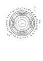
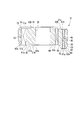
- FIG. 5 is a cross-sectional view taken along the line IV-IV of FIG. 4 showing a piston body of a shock absorber according to an embodiment of the present invention. It is a top view showing a piston main part of a buffer concerning one embodiment of the present invention.
- shock absorber according to an embodiment of the present invention will be described below with reference to the drawings.
- the shock absorber 10 of the present embodiment is a fluid pressure shock absorber that uses liquid or gas as a working fluid. Specifically, it is a hydraulic shock absorber using oil as a working fluid. As shown in FIG. 1, the shock absorber 10 has a cylinder 11 in which a working fluid is enclosed. The cylinder 11 has a bottomed cylindrical shape whose one end (upper side in FIGS. 1 and 2) is open and the other end (lower side in FIGS. 1 and 2) is closed. In the cylinder 11, a piston 12 as a valve body is slidably inserted.
- the piston rod 13 is inserted into the cylinder 11.
- the piston 12 is connected to one end side of the piston rod 13 by a nut 14 shown in FIGS.
- the piston rod 13 extends to the outside of the cylinder 11 at the other end side (upper side in FIGS. 1 and 2).
- the other end of the piston rod 13 whose one end side is connected to the piston 12 in this manner is inserted into a rod guide and an oil seal (not shown) attached to the opening of the cylinder 11 and extends outside the cylinder 11 There is.
- the piston 12 is an internal side of the cylinder 11, a first chamber 19 on the bottom side (lower side in FIGS. 1 and 2) of the cylinder 11 (not shown) and an opening side (FIG. 1 and FIG. 2) from which the piston rod 13 extends. And the second chamber 20).
- the piston rod 13 has a main shaft 25, and an attachment shaft 26 at an end in the cylinder 11 and smaller in diameter than the main shaft 25.
- an end face 27 along the direction orthogonal to the axial direction is formed at the end of the main shaft 25 at the attachment shaft 26 side.
- An external screw 28 is formed on the mounting shaft 26 so as to screw the female screw 30 of the nut 14 in a predetermined range opposite to the main shaft 25.
- the piston 12 as a valve main body has an annular piston main body 31 and an annular band-like sliding contact member 33 mounted on the outer peripheral surface of the piston main body 31 and in sliding contact with the inner peripheral surface of the cylinder 11.
- the piston 12 formed of the piston main body 31 and the sliding contact member 33 has an annular shape.
- the piston body 31 is made of metal.
- the piston body 31 is integrally formed by sintering.
- the sliding contact member 33 is made of synthetic resin.
- the central axis line of the piston main body 31 and the piston 12 to which the sliding contact member 33 is integrally mounted are made to coincide with each other.
- the axial direction which is a direction along a central axis line corresponds with piston main body 31 and piston 12
- the radial direction which is a direction which intersects perpendicularly with a central axis line
- the circumferential direction which is a direction around a central axis line corresponds.
- the central axes of the piston body 31 and the piston 12 will be referred to as a piston axial center.
- the axial direction of the piston body 31 and the piston 12 is referred to as a piston axial direction.
- the radial direction of the piston body 31 and the piston 12 is referred to as a piston radial direction.
- the circumferential direction of the piston main body 31 and the piston 12 is referred to as a piston circumferential direction.
- One end face 31A on the side of the first chamber 19 in the axial direction of the piston main body 31 mainly constitutes one end face 12A on the side of the first chamber 19 in the axial direction of the piston 12.
- the other end surface 31B on the side of the second chamber 20 in the axial direction of the piston main body 31 mainly constitutes the other end surface 12B on the side of the second chamber 20 in the axial direction of the piston 12.
- An insertion hole 35 for inserting the mounting shaft portion 26 of the piston rod 13 without a gap is formed in the axial center of the piston 12 at the radial center of the piston 12, that is, at the radial center of the piston body 31.
- the insertion hole 35 is formed on the inner side of the radially inner inner peripheral portion of the piston 12.
- the piston body 31 is formed with a first passage 41, a second passage 42 and a third passage 43 which all extend linearly in the axial direction of the piston at positions outside of the insertion hole 35 in the radial direction.
- the first passage 41, the second passage 42 and the third passage 43 are all formed in parallel to the piston axial direction.
- the first passage 41, the second passage 42 and the third passage 43 provided in the piston main body 31 penetrate the piston 12 in the axial direction, and make the first chamber 19 and the second chamber 20 communicate with each other. Is possible.
- the first passage 41 and the third passage 43 are disposed on the outer peripheral side of the piston body 31 in the radial direction.
- the second passage 42 is disposed on the radially inner side of the piston body 31. Therefore, in the piston main body 31, the second passage 42 is disposed at a position closer to the insertion hole 35 than the first passage 41 and the third passage 43.
- first passages 41, second passages 42 and third passages 43 are respectively provided in the piston main body 31.
- the first passage 41, the second passage 42 and the third passage 43 are provided in the same number, specifically at four places.
- the first passage 41 and the third passage 43 have substantially the same distance from the piston axis.
- the first passage 41 and the third passage 43 are alternately arranged at equal intervals in the circumferential direction of the piston main body 31.
- the second passages 42 are aligned one by one with the first passages 41 in the circumferential direction of the piston.
- the plurality of first passages 41 have the same shape, and are arranged at equal distances from the piston axis.
- the first passage 41 has an elongated hole shape whose width in the circumferential direction of the piston is larger than the width in the radial direction of the piston.
- the first passage 41 is curved in an arc around the piston axis.
- the first passage 41 has an opening 41 a on the side of the first chamber 19 and an opening 41 b on the side of the second chamber 20.
- the opening 41 a is open on the outer peripheral side of one end face 31 A of the piston body 31 on the first chamber 19 side, and is open on the outer peripheral side of one end face 12 A of the piston 12 on the first chamber 19 side.
- the opening 41 b is open on the outer peripheral side of the other end surface 31 B of the piston body 31 on the second chamber 20 side, and is open on the outer peripheral side of the other end surface 12 B of the piston 12 on the second chamber 20 side. As shown in FIGS. 4 and 6, the openings 41a and 41b are also wider in the circumferential direction of the piston than in the radial direction of the piston, and are curved in an arc around the piston axis.
- the plurality of second passages 42 have the same shape, and are arranged at equal distances from the piston axis.
- the second passage 42 is in the form of an elongated hole whose width in the circumferential direction of the piston is larger than the width in the radial direction of the piston.
- the second passage 42 is curved in an arc around the piston axis.
- the second passage 42 has an opening 42 a on the side of the first chamber 19 and an opening 42 b on the side of the second chamber 20.
- the opening 42 a is open on the inner peripheral side of one end surface 31 A of the piston main body 31 and is open on the inner peripheral side of one end surface 12 A of the piston 12.
- the opening 42 b is open on the inner peripheral side of the other end surface 31 B of the piston main body 31, and is open on the inner peripheral side of the other end surface 12 B of the piston 12.
- the opening 42a is closer to the inner peripheral side of the piston main body 31 than the opening 41a in the one end surface 31A
- the opening 42b is closer to the inner peripheral side of the piston main body 31 than the opening 41b in the other end surface 31B.
- the openings 42a and 42b are also wider in the circumferential direction of the piston than in the radial direction of the piston, and are curved in an arc around the axial center of the piston.
- the plurality of third passages 43 have the same shape and are arranged at equal distances from the piston axis.
- the third passage 43 is curved in an arc around the piston axis.
- the third passage 43 has an opening 43 a on the side of the first chamber 19 and an opening 43 b on the side of the second chamber 20.
- the opening 43 a is open on the outer peripheral side of one end surface 31 A of the piston main body 31 and is open on the outer peripheral side of one end surface 12 A of the piston 12.
- the opening 43 b is open on the outer peripheral side of the other end surface 31 B of the piston main body 31 and is open on the outer peripheral side of the other end surface 12 B of the piston 12.
- the openings 43a and 43b are also curved in an arc shape around the piston axis.
- a plurality of, specifically four, first sheets 51 having the same shape are provided side by side along the circumferential direction of the piston.
- the plurality of first sheets 51 are independently formed at mutually separated positions in the piston main body 31.
- the plurality of first sheets 51 are provided at equal intervals in the piston circumferential direction.
- the plurality of first sheets 51 are so-called deformed sheets that are not circular (annular).
- the plurality of first sheets 51 are provided so as to protrude outward in the piston axial direction from an end face portion 31 a surrounding the outer periphery of the first sheet 51 in one end face 31A of the piston main body 31 . That is, the plurality of first sheets 51 are provided so as to protrude to the side of the first chamber 19 opposite to the other end surface 31B. As shown in FIG. 4, the plurality of first sheets 51 have a frame-shaped sheet main body 52 at the tip end on the protruding side.
- Each of the plurality of first sheets 51 is provided so as to surround the entire periphery of the opening 41 a on the side of the first chamber 19 of the corresponding one of the plurality of first passages 41.
- one sheet main body portion 52 of the plurality of first sheets 51 is provided so as to surround the entire circumference of the opening 41 a of the one first passage 41.
- the seat main body portion 52 in which the opening 41a of the first passage 41 is formed is also wider in the circumferential direction of the piston than in the radial direction of the piston and in an arc shape centered on the piston axis It is curved.
- one of the first sheets 51 is disposed to surround the entire opening 41a of the pair of first passages 41. That is, the first sheet 51 is provided so as to surround one or more of the openings 41a of the first passage 41, and a plurality of the first sheets 51 are disposed apart in the circumferential direction of the piston.
- a third passage 43 is disposed at a central position between the first sheet 51 and the first sheet 51 adjacent in the circumferential direction of the piston main body 31.
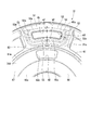
- Each of the sheet main body portions 52 of the plurality of first sheets 51 has a pair of radial direction sheet portions 53, an outer side sheet portion 54, and an inner side sheet portion 55.
- the pair of radial direction seat portions 53 extend linearly in the radial direction of the piston main body 31.
- the outer sheet portion 54 extends in an arc shape in the circumferential direction of the piston main body 31.
- the inner seat portion 55 extends in an arc shape in the circumferential direction of the piston main body 31 on the piston axial center side in the radial direction of the piston main body 31 than the outer seat portion 54.
- the outer seat portion 54 is curved in an arc around the piston axis.
- the outer sheet portion 54 connects end portions of the pair of radial direction sheet portions 53 on the opposite side to the piston axial center in the radial direction of the piston main body 31.
- the inner seat portion 55 is curved in an arc around the piston axis.
- the inner sheet portion 55 connects the end portions on the piston axial center side in the piston radial direction of the pair of radial direction sheet portions 53.
- all the outer seat portions 54 are arranged on the same circle centered on the piston axis. All the inner seat portions 55 are also arranged on the same circle centered on the piston axis.
- seat 51 becomes a plane which orthogonally crosses to the piston axial center as shown in FIG.
- the sheet surfaces 52a of all the first sheets 51 are arranged in the same plane.
- the seat width w1 in the piston radial direction of the outer seat portion 54 on the outer side in the piston radial direction is greater than the seat width w2 in the piston radial direction of the inner seat portion 55 on the piston radial direction Too big.
- the seat width w3 in the piston circumferential direction of the radial seat portion 53 is equal to the seat width w1 in the piston radial direction of the outer seat portion 54, and is larger than the seat width w2 in the piston radial direction of the inner seat portion 55.
- the seat width w1 is the width in the piston radial direction of the seat surface 54a provided on the outer seat 54 of the seat surface 52a of the seat body 52.
- the seat width w2 is the width in the piston radial direction of the seat surface portion 55a provided in the inner seat portion 55 of the seat surface 52a.
- the seat width w3 is the width of the seat surface portion 53a provided in the radial direction seat portion 53 of the seat surface 52a in the circumferential direction of the piston.
- the second passage 42 is disposed on the inner circumferential side relative to the inner sheet portion 55 in the piston radial direction. That is, the plurality of openings 42a on the side of the first chamber 19 are disposed on the inner circumferential side relative to the inner seat portion 55 in the piston radial direction.
- a second sheet 61 having a ring shape is formed closer to the piston axial center than the plurality of first sheets 51 in the piston radial direction. And are provided separately from each other.
- the second sheet 61 is shown in FIG. 2 from the end surface 31a surrounding the plurality of first and second sheets 51 and 61 of the one end surface 31A and the end surface 31b closer to the piston axial center than the second sheet 61 in the piston main body 31.
- it is provided to project outward in the axial direction of the piston. That is, the second sheet 61 is provided so as to protrude toward the first chamber 19 which is the opposite side to the other end surface 31B.
- the second sheet 61 is provided so as to project outward in the piston axial direction with respect to the end face 31a surrounding the outer periphery and the end face 31b surrounding the inner periphery.
- the second sheet 61 exerts a damping force at a high speed range of the piston speed, and therefore, unlike the variant of the first sheet 51, in order to apply a set load to the first disc valve described later. It has an annular shape centered on the piston axis. That is, the second sheet 61 is separated inward in the piston radial direction from the first sheet 51 over 360 ° in the piston circumferential direction. Since the first sheet 51 is intermittently arranged in the circumferential direction of the piston, the annular second sheet 61 is a portion which overlaps the first sheet 51 in the circumferential direction of the piston and is separated in the radial direction of the piston have.
- openings 42a of all the second passages 42 are opened in an end surface portion 31b adjacent to the second seat 61 in the piston radial direction.
- the second sheet 61 surrounds the openings 42a of all the second passages 42 outside the openings 42a of all the second passages 42 in the piston radial direction, and the openings 42a of all the second passages 42 It is spaced apart in the radial direction. Specifically, the second sheet 61 is provided between them so as to separate all the first sheets 51 and the openings 42 a of all the second passages 42.
- the second seat 61 is formed in an annular shape centered on the piston axial center. As shown in FIG. 5, a groove 63 recessed in the piston axial direction is provided between the respective inner sheet portions 55 and the second sheet 61 of all the first sheets 51. In other words, a gap is provided between the respective inner sheet portions 55 of all the first sheets 51 and the second sheet 61.
- the bottom surface of the groove 63 constitutes an end surface portion 31 a.
- the second sheet 61 is a flat surface in which a seat surface 61a, which is a tip surface on the protruding side, is orthogonal to the piston axial center.
- the second sheet 61 is provided to surround the opening 42 a of the second passage 42.
- the second sheet 61 is disposed on the inner side in the piston radial direction with respect to the first sheet 51 so as to be separated from the first sheet 51 in the piston radial direction.
- the seat width w2 in the piston radial direction of the inner seat portion 55 inside the piston radial direction is greater than the seat width w1 in the piston radial direction of the outer seat portion 54 outside the piston radial direction. Is also getting smaller.
- the second sheet 61 can be disposed on the outer side in the piston radial direction.
- the degree of freedom of the flow passage cross-sectional area of the second passage 42 is increased by, for example, increasing the flow passage cross-sectional area of the second passage 42, and the tunability also increases.
- the height in the projecting direction of the second sheet 61 is lower than the height in the projecting direction of the first sheet 51.
- the height position of the seat surface 52a of the first sheet 51 in the piston axial direction is higher than the height position of the seat surface 61a of the second sheet 61 in the piston axial direction. If it is low.
- the plurality of first sheets 51 located outside in the radial direction of the piston main body 31 is located at the end face of the second sheet 61 in which the position of the seat surface 52a which is the end face on the protruding side is inside It is located inside in the projecting direction than the position of a certain sheet surface 61a.
- annular central sheet 66 is formed on the piston axial center side in the piston radial direction with respect to the openings 42a of the plurality of second passages 42. It is provided apart from the opening 42 a of the passage 42. In other words, the central sheet 66 is provided on the inner side in the piston radial direction than the openings 42 a of all the second passages 42.
- the central seat 66 extends in the circumferential direction of the piston main body 31 so as to surround the entire circumference of the insertion hole 35, and has an annular shape centered on the piston axial center. As shown in FIG.
- the central seat 66 is provided so as to project to the first chamber 19 side which is the opposite side to the piston axial direction outer side, that is, the other end surface 31 B, from the end surface portion 31 b on the piston circumferential direction outer side There is.
- the tip end surface 66a on the protruding side of the central seat 66 is a plane orthogonal to the piston axis.
- annular passage 67 is formed between the second sheet 61 and the central sheet 66 so as to be recessed in the piston axial direction with respect to the seat surface 61a and the tip surface 66a. As shown in FIG. 4, the annular passage 67 has an annular shape centered on the piston axis. At the bottom of the annular passage 67, the openings 42a of all the second passages 42 are open.
- the height in the projecting direction of the center sheet 66 is lower than the height in the projecting direction of the second sheet 61.
- the height position of the front end surface 66a of the center sheet 66 in the piston axial direction has a positive direction of the projection direction rather than the height position of the seat surface 61a of the second sheet 61 in the piston axial direction. If it is lower.
- the position of the leading end surface 66a on the protruding side of the center sheet 66 is disposed inward in the protruding direction than the position of the sheet surface 61a that is the leading end surface on the protruding side of the second sheet 61.
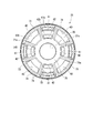
- a plurality of, specifically four, third sheets 71 having the same shape are provided side by side along the circumferential direction of the piston.
- the plurality of third seats 71 are provided at equal intervals in the circumferential direction of the piston main body 31.
- the plurality of third sheets 71 are provided so as to project outward in the piston axial direction from an end surface portion 31 c surrounding the outer periphery of the third sheet 71 in the other end surface 31 B in the piston main body 31. . That is, the plurality of third sheets 71 are provided so as to protrude toward the second chamber 20 which is the opposite side to the one end surface 31A.
- each of the plurality of third sheets 71 is provided so as to surround the opening 43b of the corresponding one of the plurality of third passages 43 over the entire circumference. Specifically, one of the plurality of third sheets 71 is provided so as to surround the entire circumference of the opening 43 b of one third passage 43.
- one of the third sheets 71 is arranged to surround the entire opening 43b of the pair of third passages 43. Ru.
- the opening 41 b of the first passage 41 and the opening 42 b of the second passage 42 are disposed at a central position between the third sheet 71 and the third sheet 71 adjacent in the circumferential direction of the piston main body 31.
- Each of the plurality of third sheets 71 includes a pair of radial direction seat portions 73 extending in the piston radial direction and a circumferential direction seat portion 74 extending in the circumferential direction of the piston.
- the plurality of third seats 71 have a central seat portion 75 disposed closer to the piston axial center in the piston radial direction than the radial seat portion 73, which is common to all of them.
- all circumferential seat portions 74 are arranged on the same circle centered on the piston axis.
- seat part 74 has connected the outer side edge parts in the piston radial direction of a pair of radial direction sheet
- the central seat portion 75 is provided so as to surround the entire circumference of the insertion hole 35 while connecting the end portions on the piston axial center side in the piston radial direction of the radial seat portions 73 of all the third seats 71.
- the sheet surfaces 71a which are the tip surfaces on the protruding side, are disposed on the same plane, and are connected in the circumferential direction of the piston.
- the seat surfaces 71a of all the third seats 71 are one plane orthogonal to the piston axis.
- a single restriction member 81 and a single restriction are formed.
- the nut 14 is screwed on the female screw 30 with the male screw 28 protruding from the regulating member 98 of the mounting shaft 26.
- the piston 12 is attached such that the first sheet 51, the second sheet 61 and the central sheet 66 face the nut 14 and the third sheet 71 faces the end face 27.
- the small diameter disc 96, the regulating disc 97 and the regulating member 98 are all stacked with their radial movement restricted by the mounting shaft 26, and they are held between the end face 27 of the piston rod 13 and the nut 14 in this stacked state. Then, at least the inner peripheral side of these is fixed to the piston rod 13 so as not to move in the axial direction. As a result, all of the disc valves 84, 92, 95 are clamped so as not to move in the axial direction relative to the piston rod 13 only on the inner peripheral side.
- the restriction member 81 has an annular shape.
- the restricting member 81 fits the mounting shaft 26 on the inner peripheral side.
- the outer diameter of the restriction member 81 is larger than the outer diameter of the end surface 27.
- the restriction disc 82 has an annular shape, and the mounting shaft portion 26 is fitted on the inner peripheral side.
- the outer diameter of the restricting disc 82 is larger than the outer diameter of the restricting member 81.
- the small diameter disc 83 has an annular shape, and the mounting shaft portion 26 is fitted on the inner peripheral side.
- the outer diameter of the small-diameter disk 83 is smaller than the outer diameter of the regulating member 81 and substantially the same diameter as the outer diameter of the end surface 27.
- the disc valve 84 includes, in order from the small-diameter disc 83, one single-piece disc 101, one single-piece disc 102, a plurality of pieces, specifically two pieces of single-piece discs 103 of the same outer diameter, Specifically, two single disks 104 having the same outer diameter are stacked.
- Each of the single disks 101 to 104 has an annular shape, and the mounting shaft portion 26 is fitted on the inner peripheral side.
- the outer diameter of the single-piece disc 101 is smaller than the outer diameter of the regulating member 81 and larger than the outer diameter of the small-diameter disc 83.
- the outer diameter of the single disc 102 is larger than that of the single disc 101.
- the outer diameter of the plurality of single disks 103 is larger than that of the single disk 102.
- the outer diameter of the plurality of single disks 104 is larger than the single disk 103. Therefore, in the disk valve 84, the outer diameter of the single disk 101 is the smallest, and the outer diameter of the plurality of single disks 104 is the largest.
- the outer diameter of the plurality of single-piece discs 104 having the largest diameter is more than twice the maximum distance from the piston axial center of the seat surface 71a which is the tip end surface of the plurality of third seats 71 It has a large diameter.
- the single disk 104 disposed closest to the piston 12 abuts on the seat surface 71 a of the third sheet 71. With the single-piece disc 104 in contact with the seat surface 71 a of the third sheet 71, the disc valve 84 closes the second chamber 20 side of the third passage 43.
- the opening 41b on the second chamber 20 side of the first passage 41 and the opening 42b on the second chamber 20 side of the second passage 42 are not blocked by the disc valve 84 and are always in communication with the second chamber 20 .
- the regulating member 81 is thicker than one of the single disks 101 to 104, and is higher in rigidity than the disk valve 84 configured by these members. Further, the restricting member 81 is thicker than the restricting disc 82 and has high rigidity. When the disc valve 84 is deformed in the direction in which the disc valve 84 is released from the third seat 71, the regulating disc 82 abuts on the disc valve 84 to suppress the deformation of the disc valve 84. The regulating member 81 regulates deformation of the regulating disc 82 by a predetermined amount or more.
- the small diameter disc 91 has an annular shape, and the mounting shaft portion 26 is fitted on the inner peripheral side.
- the small diameter disc 91 has an outer diameter larger than the outer diameter of the front end surface 66 a of the central seat 66 and smaller than twice the minimum distance from the piston axial center of the seat surface 61 a of the second seat 61. There is. As a result, the small diameter disc 91 abuts on the front end surface 66 a of the center sheet 66.
- the disc valve 92 constitutes a second disc valve.
- the disc valve 92 includes, in order from the piston 12 side, a single disc 111 and a plurality of, specifically, two single discs 112 having the same outer diameter. That is, the second disk valve is configured by stacking one single disk 112 and a plurality of single disks 112 with the same outer diameter.
- Both of the single-piece disks 111 and 112 have an annular shape, and the mounting shaft portion 26 is fitted on the inner peripheral side.
- the single disc 111 has an outer diameter larger than that of the small diameter disc 91.
- the outer diameter of the plurality of single disks 112 is equal to the maximum outer diameter of the single disk 111.
- the single-piece disc 111 has a maximum outside diameter larger than the outside diameter of the seat surface 61 a of the second sheet 61 and smaller than twice the minimum distance of the first sheet 51 from the piston axial center. Thereby, the single-piece disc 111 abuts on the sheet surface 61 a of the second sheet 61 and the tip surface 66 a of the center sheet 66 but does not contact the first sheet 51, and the piston diameter between the single disc 111 and the first sheet 51 There is a gap in the direction.
- the single disc 111 is clamped at the inner side in the radial direction and always abuts the small diameter disc 91, while the outer side in the radial direction is separated from and seated on the second seat 61.
- the single-piece disc 111 closes the second chamber 42 and the first chamber 19 side of the annular passage 67.
- the disc valve 92 including the single disc 111 is provided so as to overlap the piston 12 side of the disc valve 95, and the outer periphery is mounted so as to be able to be seated on the second seat 61.
- the second sheet 61 can be disposed on the outer side in the piston radial direction.
- the seating position of the disc valve 92 on the second seat 61 can be disposed on the outside in the piston radial direction, and as a result, the rigidity of the disc valve 92 is lowered and it becomes easy to separate from the second seat 61.
- a notch 121 extending across the seat surface 61a of the second sheet 61 in the piston radial direction is formed on the outer peripheral side.
- the notch portion 121 is U-shaped and has a shape that comes off the outer periphery of the single-piece disc 111.
- the notch 121 penetrates the single disc 111 in the thickness direction.
- a plurality of such notches 121 are formed in the single disc 111 at equal intervals in the circumferential direction.
- the notch portion 121 allows the inner peripheral side and the outer peripheral side of the second sheet 61 to communicate with each other even when the single-piece disc 111 abuts on the sheet surface 61 a of the second sheet 61.
- the second passage 42 and the annular passage 67 communicate with the first chamber 19 on the outer peripheral side of the second sheet 61 via the gap between the first sheets 51. That is, the cutaway portion 121 constitutes a fixed orifice which constantly communicates the first chamber 19 and the second chamber 20 with the second sheet 61 and the single disk 112 closest to the single disk 111.
- the notch connecting the inner circumferential side and the outer circumferential side A part may be provided, and both the notch of the second sheet 61 and the notch 121 of the single disc 111 may be provided.
- the small diameter disc 93 has an annular shape, and the mounting shaft portion 26 is fitted on the inner peripheral side.
- the small diameter disc 93 has an outer diameter smaller than that of the small diameter disc 91 and is equivalent to the tip end surface 66 a of the central seat 66.
- the plurality of interposed disks 94 are disposed between the small diameter disk 93 and the disk valve 95 as a small diameter annular member.
- the plurality of interposed disks 94 have the same outer diameter.
- the plurality of interposed disks 94 form an annular shape and the mounting shaft portion 26 is fitted on the inner peripheral side.
- the interposing disc 94 has an outside diameter equal to the outside diameter of the single disc 112 of the disc valve 92.
- the distance in the piston axial direction between the seat surface 52 a of the first sheet 51 and the seat surface 61 a of the second sheet 61 is the total thickness of the disc valve 92, the small diameter disc 93 and the plurality of interposed discs 94. It is equal to That is, according to the distance in the piston axis direction between the sheet surface 52 a of the first sheet 51 and the sheet surface 61 a of the second sheet 61, the number of the plurality of interposed disks 94 is increased or decreased.
- the axial distance between the surface 52a and the seat surface 61a of the second seat 61 may be adjusted to be equal to the total thickness of the disc valve 92, the small diameter disc 93, and the plurality of interposed discs 94. it can.
- the disk valve 95 constitutes a first disk valve, and a plurality of, specifically, six single disks 125 having the same outer diameter are stacked.
- Each single disc 125 has an annular shape, and the mounting shaft portion 26 is fitted on the inner peripheral side. That is, the first disk valve is configured by stacking a plurality of single disks 125 having the same outer diameter.
- the outer diameter of the plurality of single disks 125 is larger than twice the maximum distance of the seat surface 52 a of the first sheet 51 from the piston axial center.
- the single disc 125 closest to the disc valve 92 of the disc valve 95 abuts on the seat surface 52 a and is seated on the seat main body 52 of the first seat 51.
- the single disc 125 closes the first chamber 19 side of the first passage 41 in this state.
- the single disc 125 on the side closest to the disc valve 92 of the first seat 51 and the disc valve 95 there is not formed a notch that causes the first passage 41 to always communicate with the first chamber 19.
- the second seat 61 disposed on the inner peripheral side of the inner seat portion 55 is formed in an annular shape substantially concentric with the disc valve 95.
- the disc valve 95 is mounted so as to be able to be seated on the first seat 51.
- the diameter of the seating position of the disc valve 95 on the first seat 51 is larger than the diameter of the seating position of the disc valve 92 on the second seat 61. Therefore, the disk valve 95 has lower rigidity than the disk valve 92 and is easy to open. Therefore, at the time of valve opening, the valve is opened so that the outer sheet portion 54 and the inner sheet portion 55 are separated in order. Further, as described above, since the sheet width w1 of the outer sheet portion 54 of the first sheet 51 is larger than the sheet width w2 of the inner sheet portion 55, the contact area between the disc valve 95 and the outer sheet portion 54 is Therefore, the pressure receiving area of the valve seated on the outer seat can be suppressed from being reduced. Further, it is possible to suppress the leakage of the working fluid from between the first sheet 51 and the disk valve 95 until the disc valve 95 opens.
- the inner sheet portion 55 of the first sheet 51 With respect to the sheet width w1 of the outer sheet portion 54 having a high degree of contribution to leakage suppression, the inner sheet portion 55 having a low degree of contribution to leakage suppression
- the seat width w2 is reduced, and accordingly, the second seat 61 is disposed on the outer side in the piston radial direction. Since the second seat 61 is disposed on the outer side in the piston radial direction, the seating position of the disc valve 92 on the second seat 61 becomes the outer side in the piston radial direction, and the rigidity of the disc valve 92 decreases to separate from the second seat 61 It becomes easy to sit. Moreover, it becomes possible to enlarge the flow-path cross-sectional area of the 2nd channel
- the opening 43 a on the first chamber 19 side of the third passage 43 is not closed by the disc valves 92 and 95 and always communicates with the first chamber 19.
- the small diameter disc 96 has an annular shape, and the mounting shaft portion 26 is fitted on the inner peripheral side.
- the outer diameter of the small diameter disc 96 is slightly smaller than the outer diameter of the front end surface 66 a of the central sheet 66.
- the restriction disc 97 has an annular shape, and the mounting shaft portion 26 is fitted on the inner peripheral side.
- the outer diameter of the restriction disk 97 is larger than the outer diameter of the small diameter disk 96.
- the regulating member 98 has an annular shape.
- the restricting member 98 fits the mounting shaft 26 on the inner peripheral side.
- the restriction member 98 has an outer diameter smaller than the outer diameter of the restriction disk 97 and a larger diameter than the outer diameter of the small diameter disk 96.
- the regulating member 98 is thicker than one disc of the single disc 125, and is higher in rigidity than the disc valve 95 composed of these. Further, the regulating member 98 is thicker than the regulating disc 97 and has high rigidity.
- the regulating disc 97 abuts on the disc valve 95 to suppress the deformation of the disc valve 95.
- the regulating member 98 regulates deformation of the disc valve 95 by a predetermined amount or more.
- a large-diameter disc valve 95 to be placed and a small-diameter disc valve 92 to be seated on the second seat 61 are provided on the piston 12 to suppress the flow of working fluid and generate a damping force.
- the piston rod 13 moves to the extension side to increase the amount of protrusion from the cylinder 11 and the piston 12 moves to the second chamber 20 side, the flow of the working fluid flowing from the second chamber 20 toward the first chamber 19 is Restrain to generate the extension side damping force. Therefore, the plurality of first passages 41 and the plurality of second passages 42 are formed in parallel.
- a plurality of third passages 43 of the piston 12, a plurality of third seats 71 of the piston 12, and a disc valve 84 seated on the third seats 71 are provided in the piston 12 to control the flow of the working fluid to dampen it. Generate force.
- the piston rod 13 moves to the compression side to increase the amount of entry into the cylinder 11 and the piston 12 moves to the first chamber 19 side, the flow of working fluid flowing from the first chamber 19 toward the second chamber 20 is Suppress to generate a contraction side damping force.
- the pressure of the second chamber 20 is made higher than the pressure of the first chamber 19 by the piston 12 moving with the piston rod 13.
- the working fluid in the second chamber 20 is introduced into the plurality of first passages 41 from the openings 41b of the normally open openings and acts on the disc valve 95 from the openings 41a.
- the working fluid of the second chamber 20 is introduced into the plurality of second passages 42 from the openings 42 b of the respective constant openings, exits from the openings 42 a into the annular passage 67 and acts on the disc valve 92.
- the disc valve 95 opens and closes the plurality of first passages 41 having the openings 41 a on the outer peripheral side of one end face 12 A of the piston 12, the first provided so as to surround the openings 41 a of the first passages 41.
- the seating position on the seat 51 is on the outer side in the piston radial direction of the piston 12.
- the disc valve 95 has low rigidity. For this reason, the disc valve 95 is easily detached from the first seat 51. That is, the first disk valve opens earlier than the second disk valve.
- the disc valve 95 is seated on the plurality of first seats 51, which are all spaced apart in the circumferential direction of the piston, and the so-called odd-shaped seats, all the pressure is applied even if the flow rate is small.
- the disc valve 95 is easier to open. For this reason, the disc valve 95 opens even in the low speed region where the piston speed is low (a range less than v1 in FIG. 8), particularly from the very low speed region where the piston speed is low. That is, in the low speed region where the piston speed is low, in particular from the very low speed region where the piston speed is low, the working fluid in the first passage 41 causes the disk valve 95 to separate from the first seat 51 to open it. As a result, the working fluid flows from the second chamber 20 to the first chamber 19 at a flow rate corresponding to the opening amount of the disc valve 95 and the plurality of first sheets 51 via the plurality of first passages 41. Therefore, as shown by a portion a1 of the solid line X1 in FIG. 8, a damping force of the valve characteristic (the damping force is substantially proportional to the piston speed) is generated.
- the sheet width w2 of the inner sheet portion 55 having a low degree of contribution to leakage suppression is reduced, the sheet width w1 of the outer sheet portion 54 having a high degree of contribution to leakage suppression is the inner sheet portion
- the sheet width of 55 is larger than w2. Therefore, the contact area between the disc valve 95 and the outer seat portion 54 can be secured, and the leak of the working fluid before the disc valve 95 opens can be suppressed.
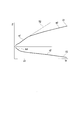
- FIG. 8 is a characteristic diagram showing the relationship between the piston speed and the damping force of the shock absorber according to the present embodiment.
- the horizontal axis (Vp) represents the piston speed.
- the vertical axis (Fd) represents the damping force.
- the working fluid in the plurality of first passages 41 leaves the disc valve 95 away from the first sheet 51 and is opened, and the plurality of second passages 42 and annular
- the working fluid in the passage 67 separates the disk valve 92 from the circumferentially long second sheet 61 to open the valve.
- the working fluid flows from the second chamber 20 to the first chamber 19 from the plurality of first passages 41 through the space between the disc valve 95 and the plurality of first sheets 51, and the plurality of second passages 42. And, it flows from the annular passage 67 between the disc valve 92 and one long circumferential second seat 61.
- the working fluid of the plurality of second passages 42 and the annular passage 67 separates the disc valve 92 from the second seat 61 at a relatively low piston speed in the middle and high speed region and opens the valve.
- a large amount of working fluid flows from the second chamber 20 to the first chamber 19 from the plurality of second passages 42 and the annular passage 67 between the disc valve 92 and the second seat 61. Therefore, as shown by a portion a2 of the solid line X1 shown in FIG. 8, the damping force characteristic of the saturation characteristic is suppressed from the relatively low piston speed in the middle and high speed region to the rise of the piston speed. In other words, in the middle and high speed region, the damping force does not rise sharply with respect to the rise of the piston speed, but becomes the damping force characteristic of the saturation characteristic which gradually rises.
- the seat width w2 of the inner seat portion 55 of the first seat 51 is smaller than the seat width w1 of the outer seat portion 54, the seating position of the disc valve 92 on the second seat 61 Since the disc valve 92 can be disposed on the outer side in the radial direction, the rigidity of the disc valve 92 is lowered and it is easy to take a seat off the second seat 61. Further, since the sheet width w2 of the inner sheet portion 55 of the first sheet 51 is smaller than the sheet width w1 of the outer sheet portion 54, the second sheet 61 can be disposed on the outer side in the piston radial direction. The length is long.
- the flow passage cross-sectional area of the second passage 42 can be increased by disposing the second sheet 61 on the outer side in the piston radial direction.
- the working fluid of the plurality of second passages 42 and the annular passage 67 separates the disc valve 92 from the second seat 61 and opens the valve from the state where the piston speed is lower.
- the working fluid from the plurality of second passages 42 and the annular passage 67 flows more through the space between the disc valve 92 and the second seat 61. That is, it is a damping force characteristic of the saturation characteristic which suppresses the rise of the damping force with respect to the rise of the piston speed.
- the working fluid is caused by this sliding. It flows from the second chamber 20 to the first chamber 19. Thereby, the flow of the working fluid is controlled to generate a damping force.
- the pressure of the first chamber 19 is raised higher than the pressure of the second chamber 20 by the piston 12 moving with the piston rod 13.
- the working fluid is introduced into the plurality of third passages 43 from the respective constant opening openings 43a and acts on the disc valve 84 from the openings 43b.
- the working fluid in the third passage 43 does not cause the disc valve 84 to be separated from the third seat 71.
- the working fluid of the first chamber 19 flows from the first chamber 19 to the second chamber 20 through the notch 121 of the single disk 111 of the disk valve 92, the annular passage 67 and the plurality of second passages 42.
- the flow passage cross-sectional area becomes constant, as shown by a portion b1 of the solid line X3 shown in FIG. 8, a damping force of the orifice characteristic (the damping force is substantially proportional to the square of the piston speed) is generated.
- the working fluid in the third passage 43 causes the disk valve 84 to be released from the third seat 71 to open the valve.
- the working fluid flows from the first chamber 19 to the second chamber 20 via the plurality of third passages 43 with a flow passage cross-sectional area corresponding to the valve opening amount of the disc valve 84 and the plurality of third sheets 71 . Therefore, as shown by a portion b2 of the solid line X3 shown in FIG. 8, a damping force of the valve characteristic (the damping force is approximately proportional to the piston speed) is generated.
- Patent Document 1 described above describes a shock absorber in which the valve characteristics in the low speed range and the valve characteristics in the high speed range can be set independently. Further, Patent Document 2 describes a shock absorber in which the damping force characteristic from the low speed region to the medium speed region of the piston speed is made substantially linear by a damping valve.
- the shock absorber 10 includes a plurality of first sheets 51 disposed on the piston 12 so as to be spaced apart in the circumferential direction of the piston, and the first sheets 51 inward of the first sheets 51 in the piston radial direction. And a second seat 61 which is spaced apart in the piston radial direction and which is lower than the first seat 51, and further, a large diameter disc valve 95 which can be seated on the plurality of first seats 51; A small diameter disc valve 92 capable of being seated on the seat 61 is provided.
- the disc valve 95 opens and closes the plurality of first passages 41 having the openings 41 a on the outer peripheral side of one end face 12 A of the piston 12, the disc valve 95 has a seating position on the first seat 51 at the piston 12. And the rigidity is low and it is easy to leave the first sheet 51. Moreover, the disc valve 95 is provided so as to surround the opening 41 a of the first passage 41, and is seated on a plurality of short circumferential first sheets 51 spaced apart in the circumferential direction of the piston. For this reason, the pressure to be loaded is likely to rise, and the disc valve 95 is easier to open.
- the disc valve 95 opens from the low speed region where the piston speed is low, and causes the working fluid to flow from the second chamber 20 to the first chamber 19 via the space between the plurality of first sheets 51. Therefore, a substantially linear damping force is generated from the low speed region where the piston speed is low.
- the sheet width w2 of the inner sheet portion 55 on the inner side in the piston radial direction which has a low degree of contribution to leakage suppression, is reduced, the outer side sheet portion on the piston radial direction outer side having a high degree of contribution to leakage suppression
- the sheet width w1 of 54 is larger than the sheet width w2 of the inner sheet portion 55. Therefore, it is possible to suppress the leak of the working fluid in the very low speed region until the disc valve 95 opens.
- the working fluid flows from the plurality of first passages 41 to the disk valve 95 and the plurality of first sheets 51 from the second chamber 20 to the first chamber 19.
- the seat width w2 of the inner seat portion 55 of the first seat 51 is smaller than the seat width w1 of the outer seat portion 54, the seating position of the disc valve 92 on the second seat 61 Since the disc valve 92 can be disposed on the outer side in the radial direction, the rigidity of the disc valve 92 is lowered and it is easy to take a seat off the second seat 61. Further, since the sheet width w2 of the inner sheet portion 55 of the first sheet 51 is smaller than the sheet width w1 of the outer sheet portion 54, the second sheet 61 can be disposed on the outside in the piston radial direction, and the circumferential length can be increased. There is.
- the flow passage cross-sectional area of the second passage 42 can be increased by disposing the second sheet 61 on the outer side in the piston radial direction.
- the interposed disk 94 as a small diameter annular member between the small diameter disk 93 and the disk valve 95, the piston of the seat surface 52 a of the first seat 51 and the seat surface 61 a of the second seat 61 According to the distance in the axial direction, the number of the plurality of interposed disks 94 is increased or decreased, and the distance in the piston axial direction between the seat surface 52a of the first sheet 51 and the seat surface 61a of the second sheet 61 It can be adjusted to be equal to the overall thickness of the small diameter disc 93 and the plurality of interposed discs 94. By configuring as described above, the number of laminated disks 94 can be changed, and the number of single disks 112 of the disk valve 92 can be increased or decreased.
- the working fluid from the plurality of second passages 42 and the annular passage 67 adjusts the damping force generated by flowing between the disc valve 92 and the second seat 61. be able to. That is, tunability can be secured.
- the configuration of the present invention is applied to the side that generates the damping force on the extension side, but it may be applied to the side that generates the damping force on the contraction side. It may be applied to both.
- the shock absorber includes a cylinder in which the working fluid is sealed, a valve body provided to the cylinder, and a plurality of openings opened on the outer peripheral side of one end surface of the valve body. And a plurality of first seats disposed so as to surround one or more of the first passageway and the opening of the first passageway and spaced apart in the circumferential direction of the valve main body, and the first seat Arc-shaped outer seat portion, an inner seat portion, a plurality of second passages opening on the inner peripheral side of the inner seat portion at one end face of the valve main body, and the plurality of first seats And a first disc valve having a large-diameter first disc valve whose inner and outer sides are clamped so as to be separated in the order of the outer seat portion and the inner seat portion when the valve is opened.
- the sheet width of the outer sheet portion is larger than the sheet width of the inner sheet portion.
- a second sheet formed in an annular shape substantially concentric with the first disc valve on an inner peripheral side of the inner sheet portion and surrounding the plurality of second passages It is characterized by having.
- the valve body is a piston.
- movement of the piston rod controls the flow of the working fluid to generate a damping force.
- the second sheet is formed lower than the first sheet protruding with respect to the piston, and the valve body of the first disc valve is formed.
- An annular second disc valve is provided so that the outer periphery is seated on the second seat.
- the first disc valve is opened earlier than the second disc valve.
- the damping characteristic of the valve characteristic is generated even in the low speed region where the piston speed is low.
- an annular member having a diameter smaller than that of the second disc valve is provided between the first disc valve and the second disc valve. It is characterized by Thus, the tunability can be secured.
Landscapes
- Engineering & Computer Science (AREA)
- General Engineering & Computer Science (AREA)
- Mechanical Engineering (AREA)
- Fluid-Damping Devices (AREA)
Abstract
第1通路(41)の開口(41a)の一つまたは複数を囲むように設けられ、ピストン周方向に離間して配置される第1シート(51)と、第2通路(42)の開口(42a)を囲むように設けられ、第1シート(51)よりもピストン径方向の内側に第1シート(51)とピストン径方向に離間して配置される、第1シート(51)よりも低い第2シート(61)と、第1シート(51)に着座可能に載置される大径の第1ディスクバルブ(95)と、第2シート(61)に着座可能に載置される小径の第2ディスクバルブ(92)と、を有し、第1シート(51)は、ピストン径方向外側の外側シート部(54)のシート幅が、ピストン径方向内側の内側シート部(55)のシート幅よりも大きい。
Description
本発明は、緩衝器に関する。
本願は、2017年8月29日に、日本に出願された特願2017-164360号に基づき優先権を主張し、その内容をここに援用する。
本願は、2017年8月29日に、日本に出願された特願2017-164360号に基づき優先権を主張し、その内容をここに援用する。
ピストンの移動速度であるピストン速度が低速域でのバルブ特性と高速域でのバルブ特性とを独立して設定できるようにした緩衝器がある(例えば、特許文献1参照)。また、ピストン速度の低速域から中速域にかけての減衰力特性を減衰バルブによるほぼリニアな特性にした緩衝器がある(例えば、特許文献2参照)。
緩衝器において、ピストン径方向に対して内側に形成された通路を囲む内側シートと、外側に形成された通路を囲む外側シートとが、段差をもって形成されている。このとき、内側シートに着座するバルブの受圧面積を大きくさせるために内側シートを拡径すると、それに対応して外側シートに着座するバルブの受圧面積が小さくなる。
本発明は、外側シートに着座するバルブの受圧面積が小さくなることを抑制することができる緩衝器を提供する。
本発明の一態様によれば、緩衝器は、作動流体が封入されるシリンダと、前記シリンダに設けられるバルブ本体と、前記バルブ本体の一端面の外周側に開口する複数の第1通路と、前記第1通路の開口の一つまたは複数を囲むように設けられ、前記バルブ本体の周方向に離間して配置される複数の第1シートと、前記第1シートを構成する、円弧状の外側シート部及び内側シート部と、前記バルブ本体の一端面の前記内側シート部の内周側に開口する複数の第2通路と、前記複数の第1シートを閉塞するように着座可能に載置され、開弁時に前記外周シート部、前記内周シート部の順に離間する環状で内周側がクランプされた大径の第1ディスクバルブと、を有する。前記外側シート部のシート幅が、前記内側シート部のシート幅よりも大きい。
上記した緩衝器によれば、外側シートに着座するバルブの受圧面積が小さくなることを抑制することができる。
本発明の一実施形態に係る緩衝器を図面を参照して以下に説明する。
本実施形態の緩衝器10は、液体あるいは気体を作動流体とする流体圧緩衝器である。具体的には、油液を作動流体とする油圧緩衝器である。図1に示すように、緩衝器10は、作動流体が封入されるシリンダ11を有している。このシリンダ11は、図示は略すが一端側(図1,図2における上側)が開口し他端側(図1,図2における下側)が閉塞された有底円筒状をなしている。シリンダ11内には、バルブ本体としてのピストン12が摺動可能に挿入されている。
シリンダ11には、ピストンロッド13が挿入されている。ピストン12は、このピストンロッド13の一端側に、図1~図3に示すナット14によって連結されている。ピストンロッド13は、他端側(図1,図2における上側)がシリンダ11の外部に延出している。このように一端側がピストン12に連結されたピストンロッド13は、その他端側が、シリンダ11の開口部に装着された図示略のロッドガイドおよびオイルシールに挿通されてシリンダ11の外部へと延出している。ピストン12は、シリンダ11の内部を、シリンダ11の図示略の底部側(図1,図2における下側)の第1室19と、ピストンロッド13が延出する開口側(図1,図2における上側)の第2室20とに画成している。
図2に示すように、ピストンロッド13は、主軸部25と、シリンダ11内の端部にあって主軸部25より小径の取付軸部26とを有している。これにより、主軸部25には、取付軸部26側の端部に軸直交方向に沿う端面27が形成されている。取付軸部26には、主軸部25とは反対側の所定範囲に上記したナット14のメネジ30を螺合させるオネジ28が形成されている。
バルブ本体としてのピストン12は、円環状のピストン本体31と、ピストン本体31の外周面に装着されてシリンダ11の内周面に摺接する円環帯状の摺接部材33とを有している。よって、ピストン本体31と摺接部材33とからなるピストン12は円環状をなしている。
ピストン本体31は、金属製である。ピストン本体31は、焼結により一体成形されている。摺接部材33は合成樹脂製である。ピストン本体31と、これに摺接部材33が一体的に装着されてなるピストン12とは、中心軸線を一致させている。これにより、ピストン本体31とピストン12とは、中心軸線に沿う方向である軸方向が一致し、中心軸線に直交する方向である径方向が一致し、中心軸線回りの方向である周方向が一致する。以下、ピストン本体31およびピストン12の中心軸線をピストン軸心と称する。ピストン本体31およびピストン12の軸方向をピストン軸方向と称する。ピストン本体31およびピストン12の径方向をピストン径方向と称する。ピストン本体31およびピストン12の周方向をピストン周方向と称する。
ピストン本体31の軸方向の第1室19側の一端面31Aは、ピストン12の軸方向の第1室19側の一端面12Aを主体的に構成している。ピストン本体31の軸方向の第2室20側の他端面31Bは、ピストン12の軸方向の第2室20側の他端面12Bを主体的に構成している。
ピストン12の径方向の中央、すなわちピストン本体31の径方向の中央には、ピストンロッド13の取付軸部26を隙間なく挿通させる挿通孔35がピストン軸方向に貫通するように形成されている。挿通孔35は、ピストン12の径方向内側の内周部の内側に形成されている。
ピストン本体31には、その径方向の挿通孔35よりも外側位置にて、いずれもピストン軸方向に直線状に延びる第1通路41、第2通路42および第3通路43が形成されている。第1通路41、第2通路42および第3通路43は、いずれも、ピストン軸方向に平行に形成されている。
ピストン本体31に設けられたこれらの第1通路41、第2通路42および第3通路43は、ピストン12を軸方向に貫通しており、第1室19と第2室20とを連通させることが可能となっている。第1通路41および第3通路43は、ピストン本体31の径方向における外周側に配置されている。第2通路42は、ピストン本体31の径方向における内周側に配置されている。よって、ピストン本体31において、第1通路41および第3通路43よりも挿通孔35に近い位置に第2通路42が配置されている。
図4に示すように、第1通路41、第2通路42および第3通路43は、それぞれピストン本体31に複数ずつ設けられている。第1通路41、第2通路42および第3通路43は、同数、具体的には四カ所ずつ設けられている。
第1通路41と第3通路43とは、ピストン軸心からの距離がほぼ同等になっている。第1通路41と第3通路43とは、ピストン本体31の周方向に交互に等間隔で配置されている。第2通路42は、一つずつが、ピストン周方向における位置を第1通路41と合わせている。
第1通路41と第3通路43とは、ピストン軸心からの距離がほぼ同等になっている。第1通路41と第3通路43とは、ピストン本体31の周方向に交互に等間隔で配置されている。第2通路42は、一つずつが、ピストン周方向における位置を第1通路41と合わせている。
複数の第1通路41は、同形状であって、ピストン軸心から等距離の位置に配置されている。第1通路41は、ピストン周方向の幅がピストン径方向の幅よりも大きい長穴形状である。第1通路41は、ピストン軸心を中心とした円弧状に湾曲している。第1通路41は、図2に示すように、第1室19側の開口41aと第2室20側の開口41bとを有している。開口41aは、ピストン本体31の第1室19側の一端面31Aの外周側に開口しており、ピストン12の第1室19側の一端面12Aの外周側に開口している。開口41bは、ピストン本体31の第2室20側の他端面31Bの外周側に開口しており、ピストン12の第2室20側の他端面12Bの外周側に開口している。図4,図6に示すように、開口41a,41bも、ピストン周方向の幅がピストン径方向の幅よりも大きく、ピストン軸心を中心とした円弧状に湾曲している。
複数の第2通路42は、同形状であって、ピストン軸心から等距離の位置に配置されている。第2通路42は、ピストン周方向の幅がピストン径方向の幅よりも大きい長穴形状である。第2通路42は、ピストン軸心を中心とした円弧状に湾曲している。第2通路42は、図2に示すように、第1室19側の開口42aと第2室20側の開口42bとを有している。開口42aは、ピストン本体31の一端面31Aの内周側に開口しており、ピストン12の一端面12Aの内周側に開口している。開口42bは、ピストン本体31の他端面31Bの内周側に開口しており、ピストン12の他端面12Bの内周側に開口している。開口42aは、一端面31Aにおける開口41aよりもピストン本体31の内周側に開口しており、開口42bは、他端面31Bにおける開口41bよりもピストン本体31の内周側に開口している。図4,図6に示すように、開口42a,42bも、ピストン周方向の幅がピストン径方向の幅よりも大きく、ピストン軸心を中心とした円弧状に湾曲している。
複数の第3通路43は、同形状であって、ピストン軸心から等距離の位置に配置されている。第3通路43は、ピストン軸心を中心とした円弧状に湾曲している。第3通路43は、図2に示すように、第1室19側の開口43aと第2室20側の開口43bとを有している。開口43aは、ピストン本体31の一端面31Aの外周側に開口しており、ピストン12の一端面12Aの外周側に開口している。開口43bは、ピストン本体31の他端面31Bの外周側に開口しており、ピストン12の他端面12Bの外周側に開口している。図4,図6に示すように、開口43a,43bも、ピストン軸心を中心とした円弧状に湾曲している。
図4に示すように、ピストン本体31の一端面31Aには、ピストン周方向に並んで複数、具体的には四カ所の同形状の第1シート51が設けられている。複数の第1シート51は、ピストン本体31においてそれぞれ互いに離れた位置に独立して形成されている。複数の第1シート51は、ピストン周方向に等間隔で設けられている。複数の第1シート51は、円形(円環状)ではない、いわゆる異形シートとなっている。
複数の第1シート51は、ピストン本体31の一端面31Aのうちの第1シート51の外周囲を囲む端面部31aから、図2に示すようにピストン軸方向の外側に突出して設けられている。すなわち、複数の第1シート51は、他端面31Bとは反対側である第1室19側に突出して設けられている。複数の第1シート51は、突出側の先端部に、図4に示すように、枠状のシート本体部52を有している。
複数の第1シート51は、それぞれが個々に、複数の第1通路41のうちの対応するものの第1室19側の開口41aをシート本体部52で全周にわたって囲むように設けられている。具体的に、複数の第1シート51のシート本体部52は、それぞれ一つが一つの第1通路41の開口41aを全周にわたって囲むように設けられている。第1通路41の開口41aが内側に形成されたシート本体部52も、開口41aと同様に、ピストン周方向の幅がピストン径方向の幅よりも大きく、ピストン軸心を中心とした円弧状に湾曲している。
第1シート51に対して第1通路41の数が例えば二倍の場合、第1シート51の一つが、二カ所一組の第1通路41の開口41aの全体を囲むように配置される。すなわち、第1シート51は、第1通路41の開口41aの一つまたは複数を囲むように設けられており、複数のものがピストン周方向に離間して配置されている。
ピストン本体31の周方向に隣り合う第1シート51と第1シート51との間の中央位置に第3通路43が配置されている。
複数の第1シート51のシート本体部52は、それぞれが、一対の径方向シート部53と、外側シート部54と、内側シート部55とを有している。一対の径方向シート部53は、ピストン本体31の径方向に直線状に延びる。外側シート部54は、ピストン本体31の周方向に円弧状に延びる。内側シート部55は、外側シート部54よりもピストン本体31の径方向におけるピストン軸心側でピストン本体31の周方向に円弧状に延びる。
外側シート部54は、ピストン軸心を中心とした円弧状に湾曲している。外側シート部54は、一対の径方向シート部53のピストン本体31の径方向におけるピストン軸心とは反対側の端部同士を結んでいる。内側シート部55は、ピストン軸心を中心とした円弧状に湾曲している。内側シート部55は、一対の径方向シート部53のピストン径方向におけるピストン軸心側の端部同士を結んでいる。複数の第1シート51は、すべての外側シート部54が、ピストン軸心を中心とした同一円上に配置されている。すべての内側シート部55も、ピストン軸心を中心とした同一円上に配置されている。複数の第1シート51のシート本体部52は、それぞれの突出側の先端面であるシート面52aが、図5に示すようにピストン軸心に直交する平面となっている。すべての第1シート51のシート面52aが同一平面に配置されている。
図7に示すように、第1シート51は、ピストン径方向外側の外側シート部54のピストン径方向のシート幅w1が、ピストン径方向内側の内側シート部55のピストン径方向のシート幅w2よりも大きい。また、径方向シート部53のピストン周方向のシート幅w3は、外側シート部54のピストン径方向のシート幅w1と同等であり、内側シート部55のピストン径方向のシート幅w2よりも大きい。なお、シート幅w1は、シート本体部52のシート面52aのうちの外側シート部54に設けられたシート面部54aのピストン径方向の幅である。シート幅w2は、シート面52aのうちの内側シート部55に設けられたシート面部55aのピストン径方向の幅である。シート幅w3は、シート面52aのうちの径方向シート部53に設けられたシート面部53aのピストン周方向の幅である。
ここで、第2通路42と第1シート51との位置関係を示すと、第2通路42は、ピストン径方向において、内側シート部55よりも内周側に配置される。つまり、第1室19側の複数の開口42aは、ピストン径方向において、内側シート部55よりも内周側に配置される。
図4に示すように、ピストン本体31の一端面31Aには、複数の第1シート51よりもピストン径方向のピストン軸心側に、環状をなす第2シート61が、複数の第1シート51とは離間して設けられている。第2シート61は、ピストン本体31において、一端面31Aの複数の第1シート51および第2シート61を囲む端面部31aおよび第2シート61よりもピストン軸心側の端面部31bから、図2に示すようにピストン軸方向の外側に突出して設けられている。すなわち、第2シート61は、他端面31Bとは反対側である第1室19側に突出して設けられている。
言い換えれば、第2シート61は、その外周囲を囲む端面部31aおよび内周囲を囲む端面部31bよりもピストン軸方向の外側に突出して設けられている。
言い換えれば、第2シート61は、その外周囲を囲む端面部31aおよび内周囲を囲む端面部31bよりもピストン軸方向の外側に突出して設けられている。
図4に示すように、第2シート61は、ピストン速度の高速域において減衰力を出すため、後段で説明する第1ディスクバルブにセット荷重を入れるために、第1シート51の異形とは異なりピストン軸心を中心とした円環状をなしている。すなわち、第2シート61は、ピストン周方向の360°に亘って、第1シート51よりもピストン径方向内側に離間している。第1シート51がピストン周方向に断続的に配置されているため、円環状の第2シート61は、第1シート51に対してピストン周方向の位置を重ね合わせてピストン径方向に離間する部分を有している。
ピストン本体31の一端面31Aには、第2シート61に対しピストン径方向内側に隣り合う端面部31bに、すべての第2通路42の開口42aが開口している。第2シート61は、すべての第2通路42の開口42aよりもピストン径方向の外側に、すべての第2通路42の開口42aを囲むように、すべての第2通路42の開口42aとはピストン径方向に離間して設けられている。具体的に、第2シート61は、すべての第1シート51とすべての第2通路42の開口42aとを仕切るように、これらの間に設けられている。
第2シート61は、上記したように、ピストン軸心を中心とした円環状に形成されている。すべての第1シート51のそれぞれの内側シート部55と第2シート61との間には、図5に示すようにピストン軸方向に凹む溝63が設けられている。言い換えれば、すべての第1シート51のそれぞれの内側シート部55と第2シート61との間に隙間が設けられている。溝63の底面は、端面部31aを構成している。第2シート61は、その突出側の先端面であるシート面61aがピストン軸心に直交する平面となっている。
第2シート61は、第2通路42の開口42aを囲むように設けられる。第2シート61は、第1シート51よりもピストン径方向の内側に第1シート51とはピストン径方向に離間して配置されている。図7に示すように、第1シート51は、ピストン径方向内側の内側シート部55のピストン径方向のシート幅w2が、ピストン径方向外側の外側シート部54のピストン径方向のシート幅w1よりも小さくなっている。このように内側シート部55のシート幅w2を小さくした分、第2シート61をピストン径方向の外側に配置できる。また、その分、第2通路42の流路断面積を大きくする等、第2通路42の流路断面積の自由度が高くなり、チューナビリティも高くなる。
図5に示すように、第2シート61の突出方向の高さは、第1シート51の突出方向の高さよりも低くなっている。言い換えれば、第2シート61のシート面61aのピストン軸方向の高さ位置よりも、第1シート51のシート面52aのピストン軸方向の高さ位置の方が、これらの突出方向を正方向とした場合に低くなっている。さらに言い換えれば、ピストン本体31の径方向の外側にある複数の第1シート51は、突出側の先端面であるシート面52aの位置が、径方向の内側にある第2シート61の先端面であるシート面61aの位置よりも、突出方向において内側に位置している。
図4に示すように、ピストン本体31の一端面31Aには、複数の第2通路42の開口42aよりもピストン径方向のピストン軸心側に、環状をなす中央シート66が、すべての第2通路42の開口42aと離間して設けられている。言い換えれば、中央シート66は、すべての第2通路42の開口42aよりもピストン径方向の内側に設けられている。
中央シート66は、挿通孔35の全周を囲むようにピストン本体31の周方向に延びており、ピストン軸心を中心とした円環状をなしている。図2に示すように、中央シート66は、そのピストン周方向外側の端面部31bよりも、ピストン軸方向の外側すなわち他端面31Bとは反対側である第1室19側に突出して設けられている。図5に示すように、中央シート66の突出側の先端面66aがピストン軸心に直交する平面となっている。
中央シート66は、挿通孔35の全周を囲むようにピストン本体31の周方向に延びており、ピストン軸心を中心とした円環状をなしている。図2に示すように、中央シート66は、そのピストン周方向外側の端面部31bよりも、ピストン軸方向の外側すなわち他端面31Bとは反対側である第1室19側に突出して設けられている。図5に示すように、中央シート66の突出側の先端面66aがピストン軸心に直交する平面となっている。
第2シート61と中央シート66との間は、これらのシート面61aおよび先端面66aよりもピストン軸方向に凹む環状通路67となっている。図4に示すように、環状通路67は、ピストン軸心を中心とする円環状である。環状通路67の底面に、すべての第2通路42の開口42aが開口している。
図5に示すように、中央シート66の突出方向の高さは、第2シート61の突出方向の高さよりも低くなっている。言い換えれば、第2シート61のシート面61aのピストン軸方向の高さ位置よりも、中央シート66の先端面66aのピストン軸方向の高さ位置の方が、これらの突出方向を正方向とした場合に低くなっている。さらに言い換えれば、中央シート66は、突出側の先端面66aの位置が、第2シート61の突出側の先端面であるシート面61aの位置よりも、突出方向において内側に配置されている。
図6に示すように、ピストン本体31の他端面31Bには、ピストン周方向に並んで複数、具体的には四カ所の同形状の第3シート71が設けられている。複数の第3シート71は、ピストン本体31の周方向に等間隔で設けられている。複数の第3シート71は、ピストン本体31において、他端面31Bのうち第3シート71の外周囲を囲む端面部31cから、図2に示すようにピストン軸方向の外側に突出して設けられている。すなわち、複数の第3シート71は、一端面31Aとは反対側である第2室20側に突出して設けられている。
図6に示すように、複数の第3シート71は、それぞれが個々に、複数の第3通路43のうちの対応するものの開口43bを全周にわたって囲むように設けられている。具体的に、複数の第3シート71は、それぞれ一つが一つの第3通路43の開口43bを全周にわたって囲むように設けられている。
なお、第3シート71に対して第3通路43の数が例えば二倍の場合、第3シート71の一つが、二カ所一組の第3通路43の開口43bの全体を囲むように配置される。ピストン本体31の周方向に隣り合う第3シート71と第3シート71との間の中央位置に、第1通路41の開口41bおよび第2通路42の開口42bが配置されている。
複数の第3シート71は、それぞれが、ピストン径方向に延びる一対の径方向シート部73と、ピストン周方向に延びる周方向シート部74とを有している。複数の第3シート71は、そのすべてに共通する、径方向シート部73よりもピストン径方向におけるピストン軸心側に配置される中央シート部75を有している。複数の第3シート71は、すべての周方向シート部74が、ピストン軸心を中心とした同一円上に配置されている。周方向シート部74は、同じ第3シート71を構成する一対の径方向シート部73のピストン径方向における外側端部同士を結んでいる。中央シート部75は、すべての第3シート71の径方向シート部73のピストン径方向におけるピストン軸心側の端部を結びつつ、挿通孔35の全周を囲むように設けられている。共通の中央シート部75を含むすべての第3シート71は、突出側の先端面であるシート面71aが、同一平面に配置されて、ピストン周方向に繋がっている。すべての第3シート71のシート面71aは、ピストン軸心に直交する一つの平面となっている。
図2に示すように、ピストンロッド13の主軸部25の端面27には、取付軸部26を挿通させた状態で、いずれも円環状をなす、一枚の規制部材81と、一枚の規制ディスク82と、一枚の小径ディスク83と、ディスクバルブ84と、ピストン12と、一枚の小径ディスク91と、ディスクバルブ92(第2ディスクバルブ)と、一枚の小径ディスク93と、複数枚の介装ディスク94と、ディスクバルブ95(第1ディスクバルブ)と、一枚の小径ディスク96と、一枚の規制ディスク97と、一枚の規制部材98とが、この順に重ねられており、この状態で、取付軸部26の規制部材98から突出するオネジ28にナット14がメネジ30において螺合されている。このとき、ピストン12は、第1シート51、第2シート61および中央シート66がナット14側に向き、第3シート71が端面27側に向いて取り付けられる。
オネジ28へのナット14の締結により、規制部材81、規制ディスク82、小径ディスク83、ディスクバルブ84、ピストン12、小径ディスク91、ディスクバルブ92、小径ディスク93、介装ディスク94、ディスクバルブ95、小径ディスク96、規制ディスク97および規制部材98は、いずれも、取付軸部26で径方向移動が規制されて積層され、この積層状態でピストンロッド13の端面27とナット14とに挟持される。すると、これらは少なくとも内周側がピストンロッド13に対し軸方向移動不可に固定される。その結果、ディスクバルブ84,92,95は、いずれも内周側のみがピストンロッド13に対し軸方向移動不可にクランプされる。
規制部材81は、円環状をなしている。規制部材81は、取付軸部26を内周側に嵌合させている。規制部材81は、外径が端面27の外径よりも大径となっている。規制ディスク82は、円環状をなして取付軸部26を内周側に嵌合させている。規制ディスク82の外径は、規制部材81の外径よりも大径となっている。小径ディスク83は、円環状をなして取付軸部26を内周側に嵌合させている。小径ディスク83の外径は、規制部材81の外径よりも小径で、端面27の外径とほぼ同径となっている。
ディスクバルブ84は、小径ディスク83側から順に、一枚の単体ディスク101と、一枚の単体ディスク102と、複数枚、具体的には2枚の同外径の単体ディスク103と、複数枚、具体的には2枚の同外径の単体ディスク104とが積層されて構成されている。
単体ディスク101~104は、いずれも円環状をなして取付軸部26を内周側に嵌合させている。単体ディスク101の外径は、規制部材81の外径よりも小径であって小径ディスク83の外径よりも大径である。単体ディスク102の外径は、単体ディスク101よりも大径である。複数枚の単体ディスク103の外径は、単体ディスク102よりも大径である。複数枚の単体ディスク104の外径は、単体ディスク103よりも大径である。よって、ディスクバルブ84において、単体ディスク101の外径が最も小径で、複数枚の単体ディスク104の外径が最も大径である。
ディスクバルブ84は、最も大径の複数枚の単体ディスク104の外径が、複数の第3シート71の突出側の先端面であるシート面71aのピストン軸心からの最大距離の二倍よりも大径となっている。複数枚の単体ディスク104のうち、最もピストン12側に配置された単体ディスク104は、第3シート71のシート面71aに当接する。単体ディスク104が第3シート71のシート面71aに当接した状態で、ディスクバルブ84は、第3通路43の第2室20側を閉じる。
第1通路41の第2室20側の開口41bおよび第2通路42の第2室20側の開口42bは、ディスクバルブ84で閉塞されることはなく、常時第2室20に連通している。
規制部材81は、単体ディスク101~104の一枚よりも厚さが厚く、これらで構成されるディスクバルブ84よりも高剛性となっている。また、規制部材81は、規制ディスク82よりも厚さが厚く高剛性となっている。規制ディスク82は、ディスクバルブ84が第3シート71から離座する方向に変形した場合に、ディスクバルブ84に当接して、ディスクバルブ84の変形を抑制する。規制部材81は、規制ディスク82の所定量以上の変形を規制する。
小径ディスク91は、円環状をなして取付軸部26を内周側に嵌合させている。小径ディスク91は、外径が、中央シート66の先端面66aの外径よりも大径で、第2シート61のシート面61aのピストン軸心からの最小距離の二倍よりも小径となっている。これにより、小径ディスク91は、中央シート66の先端面66aに当接する。
ディスクバルブ92は、第2ディスクバルブを構成する。ディスクバルブ92は、ピストン12側から順に、一枚の単体ディスク111と、複数枚、具体的には2枚の同外径の単体ディスク112とを有する。つまり、第2ディスクバルブは、一枚の単体ディスク112と、複数枚の同外径の単体ディスク112とが積層されて構成される。
単体ディスク111,112は、いずれも円環状をなして取付軸部26を内周側に嵌合させている。単体ディスク111は、小径ディスク91よりも外径が大径となっている。
複数枚の単体ディスク112は、外径が単体ディスク111の最大外径と同等になっている。
複数枚の単体ディスク112は、外径が単体ディスク111の最大外径と同等になっている。
単体ディスク111は、最大外径が、第2シート61のシート面61aの外径よりも大径で、第1シート51のピストン軸心からの最小距離の二倍よりも小径となっている。これにより、単体ディスク111は、第2シート61のシート面61aおよび中央シート66の先端面66aに当接する一方で、第1シート51には接触せず、第1シート51との間にピストン径方向の隙間を有する。単体ディスク111は、径方向の内側がクランプされて小径ディスク91に常時当接する一方、径方向外側は、第2シート61に対して離着座する。第2シート61に着座した状態で、単体ディスク111は、第2通路42および環状通路67の第1室19側を閉じる。単体ディスク111を含むディスクバルブ92は、ディスクバルブ95のピストン12側に重ねて設けられており、外周が第2シート61に着座可能に載置されている。
上記したように、第1シート51の内側シート部55のシート幅w2を外側シート部54のシート幅w1よりも小さくした分、第2シート61をピストン径方向の外側に配置できる。その分、ディスクバルブ92の第2シート61への着座位置をピストン径方向の外側に配置でき、その結果、ディスクバルブ92の剛性が下がり第2シート61から離座し易くなる。
単体ディスク111には、第2シート61のシート面61aをピストン径方向に跨いで延びる切欠部121が外周側に形成されている。切欠部121は、U字状で単体ディスク111の外周に抜ける形状を有する。切欠部121は、単体ディスク111を板厚方向に貫通している。単体ディスク111には、このような切欠部121が、周方向に等間隔で複数形成されている。切欠部121は、単体ディスク111が第2シート61のシート面61aに当接した状態でも、第2シート61の内周側と外周側とを連通させて、第2シート61の内周側の第2通路42および環状通路67と、第2シート61の外周側の第1室19とを、第1シート51間の隙間を介して連通させる。つまり、切欠部121は、第2シート61と最も単体ディスク111側の単体ディスク112とで、第1室19と第2室20とを常時連通させる固定オリフィスを構成する。なお、単体ディスク111に切欠部121を設けずに、第2シート61に、単体ディスク111が第2シート61のシート面61aに当接した状態でもその内周側と外周側とを連通させる切欠部を設けても良く、この第2シート61の切欠部と単体ディスク111の切欠部121との両方を設けても良い。
小径ディスク93は、円環状をなして取付軸部26を内周側に嵌合させている。小径ディスク93は、外径が、小径ディスク91よりも小径となっており、中央シート66の先端面66aと同等となっている。
複数枚の介装ディスク94は、小径の環状部材として小径ディスク93とディスクバルブ95との間に配置されている。複数枚の介装ディスク94は、同外径である。複数枚の介装ディスク94は、円環状をなして取付軸部26を内周側に嵌合させている。介装ディスク94は、外径がディスクバルブ92の単体ディスク112の外径と同等になっている。
ここで、第1シート51のシート面52aと、第2シート61のシート面61aとのピストン軸方向の距離は、ディスクバルブ92、小径ディスク93および複数枚の介装ディスク94の全体の厚さに同等となっている。つまり、第1シート51のシート面52aと、第2シート61のシート面61aとのピストン軸方向の距離に応じて、複数枚の介装ディスク94の枚数を増減させ、第1シート51のシート面52aと、第2シート61のシート面61aとのピストン軸方向の距離が、ディスクバルブ92、小径ディスク93および複数枚の介装ディスク94の全体の厚さと同等になるように調整することができる。
ディスクバルブ95は、第1ディスクバルブを構成し、複数枚、具体的には6枚の同外径の単体ディスク125が積層されて構成される。これら単体ディスク125は、いずれも円環状をなして取付軸部26を内周側に嵌合させている。つまり、第1ディスクバルブは、複数枚の同外径の単体ディスク125が積層されて構成される。複数枚の単体ディスク125は、外径が、第1シート51のシート面52aのピストン軸心からの最大距離の二倍よりも大径となっている。ディスクバルブ95の最もディスクバルブ92側の単体ディスク125は、シート面52aに当接して第1シート51のシート本体部52に着座する。単体ディスク125は、この状態で、第1通路41の第1室19側を閉じる。第1シート51およびディスクバルブ95の最もディスクバルブ92側の単体ディスク125には、第1通路41を第1室19に常時連通させる切欠部は形成されていない。内側シート部55の内周側に配置された第2シート61は、ディスクバルブ95と略同心の環状に形成されている。
ディスクバルブ95は、第1シート51に着座可能に載置されている。ディスクバルブ95は、第1シート51への着座位置の径が、ディスクバルブ92の第2シート61への着座位置の径よりも大径となっている。よって、ディスクバルブ95は、ディスクバルブ92よりも剛性が低く開弁し易くなっている。したがって、開弁時は、外側シート部54、内側シート部55の順に離間するように開弁する。また、上記したように、第1シート51の外側シート部54のシート幅w1を内側シート部55のシート幅w2よりも大きくしているため、ディスクバルブ95と外側シート部54との接触面積を確保することができ、外側シートに着座するバルブの受圧面積が小さくなることを抑制することができる。また、ディスクバルブ95が開弁するまでの間に、第1シート51との間から作動流体をリークさせてしまうことを抑制できる。
第1シート51の外側シート部54および内側シート部55のうち、リーク抑制に対する寄与の度合いが高い外側シート部54のシート幅w1に対して、リーク抑制に対する寄与の度合いが低い内側シート部55のシート幅w2を小さくし、その分、第2シート61をピストン径方向の外側に配置している。第2シート61をピストン径方向の外側に配置した分、ディスクバルブ92の第2シート61への着座位置がピストン径方向の外側になり、ディスクバルブ92の剛性が下がって第2シート61から離座し易くなる。また、第2シート61をピストン径方向の外側に配置した分、第2通路42の流路断面積を大きくすることが可能になる。
図2に示すように第3通路43の第1室19側の開口43aは、ディスクバルブ92,95で閉塞されることはなく、常時第1室19に連通している。
小径ディスク96は、円環状をなして取付軸部26を内周側に嵌合させている。小径ディスク96は、その外径が、中央シート66の先端面66aの外径よりも若干小径となっている。規制ディスク97は、円環状をなして取付軸部26を内周側に嵌合させている。規制ディスク97は、その外径が、小径ディスク96の外径よりも大径となっている。規制部材98は、円環状をなしている。規制部材98は、取付軸部26を内周側に嵌合させている。規制部材98は、外径が規制ディスク97の外径よりも小径で、小径ディスク96の外径よりも大径となっている。
規制部材98は、単体ディスク125の一枚よりも厚さが厚く、これらで構成されるディスクバルブ95よりも高剛性となっている。また、規制部材98は、規制ディスク97よりも厚さが厚く高剛性となっている。規制ディスク97は、ディスクバルブ95が第1シート51から離座する方向に変形した場合に、ディスクバルブ95に当接して、ディスクバルブ95の変形を抑制する。規制部材98は、ディスクバルブ95の所定量以上の変形を規制する。
ピストン12の複数の第1通路41、複数の第2通路42および環状通路67と、ピストン12の複数の第1シート51および環状の第2シート61と、複数の第1シート51に着座可能に載置される大径のディスクバルブ95と、第2シート61に着座可能に載置される小径のディスクバルブ92とが、ピストン12に設けられ作動流体の流れを抑制して減衰力を発生させる。ピストンロッド13がシリンダ11からの突出量を増やす伸び側に移動してピストン12が第2室20側に移動する際に、第2室20から第1室19に向けて流れる作動流体の流れを抑制して伸び側の減衰力を発生させる。よって、複数の第1通路41と、複数の第2通路42とは、並列に形成されている。
ピストン12の複数の第3通路43と、ピストン12の複数の第3シート71と、これら第3シート71に着座するディスクバルブ84とが、ピストン12に設けられ作動流体の流れを制御して減衰力を発生させる。ピストンロッド13がシリンダ11への進入量を増やす縮み側に移動してピストン12が第1室19側に移動する際に、第1室19から第2室20に向けて流れる作動流体の流れを抑制して縮み側の減衰力を発生させる。
緩衝器10において、ピストンロッド13がシリンダ11に対して伸び側に移動する伸び行程では、ピストンロッド13とともに移動するピストン12によって第2室20の圧力が第1室19の圧力よりも高められる。これにより、一方で、第2室20の作動流体が、複数の第1通路41にそれぞれの常時開口の開口41bから導入されて開口41aからディスクバルブ95に作用する。また、他方で、第2室20の作動流体が、複数の第2通路42にそれぞれの常時開口の開口42bから導入されて開口42aから環状通路67に出てディスクバルブ92に作用する。
このとき、ピストン12の移動速度であるピストン速度が非常に低いと、複数の第1通路41の作動流体がディスクバルブ95を第1シート51から離座させることはなく、複数の第2通路42および環状通路67の作動流体がディスクバルブ92を第2シート61から離座させることもない。そして、第2室20の作動流体は、複数の第2通路42および環状通路67から、ディスクバルブ92の単体ディスク111の切欠部121を介して第1室19に流れる。これにより、流路断面積が一定となるため、オリフィス特性(減衰力がピストン速度の2乗にほぼ比例する)の減衰力が発生する。
ここで、ディスクバルブ95が、ピストン12の一端面12Aの外周側に開口41aを有する複数の第1通路41を開閉することから、第1通路41の開口41aを囲むように設けられた第1シート51への着座位置が、ピストン12におけるピストン径方向の外側となっている。更に、ディスクバルブ95は剛性が低い。このため、ディスクバルブ95は、第1シート51から離座し易い。すなわち、第1ディスクバルブが第2ディスクバルブより先に開弁する。しかも、ディスクバルブ95は、ピストン周方向に離間して配置された複数の、いずれも周長が短い第1シート51、いわゆる異形シートに着座しているため、流量が小さくても負荷される圧力が上昇しやすい。このため、ディスクバルブ95は、さらに開弁し易い。このため、ディスクバルブ95は、ピストン速度が低速の低速域(図8のv1未満の範囲)においても、特にピストン速度が低い微低速域から開弁する。
すなわち、ピストン速度が低速の低速域において、特にピストン速度が低い微低速域から、第1通路41の作動流体がディスクバルブ95を第1シート51から離座させて開弁させる。これにより、第2室20から第1室19に、複数の第1通路41を介してディスクバルブ95と複数の第1シート51との開弁量に応じた流量で作動流体が流れる。このため、図8に実線X1の部分a1に示すように、バルブ特性(減衰力がピストン速度にほぼ比例する)の減衰力が発生する。
すなわち、ピストン速度が低速の低速域において、特にピストン速度が低い微低速域から、第1通路41の作動流体がディスクバルブ95を第1シート51から離座させて開弁させる。これにより、第2室20から第1室19に、複数の第1通路41を介してディスクバルブ95と複数の第1シート51との開弁量に応じた流量で作動流体が流れる。このため、図8に実線X1の部分a1に示すように、バルブ特性(減衰力がピストン速度にほぼ比例する)の減衰力が発生する。
なお、第1シート51において、リーク抑制に対する寄与の度合いが低い内側シート部55のシート幅w2を小さくするものの、リーク抑制に対する寄与の度合いが高い外側シート部54のシート幅w1を、内側シート部55のシート幅w2よりもよりも大きくしている。このため、ディスクバルブ95と外側シート部54との接触面積を確保することができ、ディスクバルブ95が開弁するまでの間の作動流体のリークについては、抑制することができる。
図8に、本実施形態に係る緩衝器のピストン速度と減衰力との関係を示す特性線図を示す。図8において、横軸(Vp)はピストン速度を表す。縦軸(Fd)は、減衰力を表す。図8に示すように、上記低速域よりも高速の中高速域(図8のv1以上の範囲)において、第2室20から第1室19に、複数の第1通路41からディスクバルブ95と複数の第1シート51との間を介して作動流体が流れるのみでは、図8に二点鎖線X2で示すように、減衰力が、ディスクバルブ95の剛性に依存し、ほぼリニアな特性のまま、ピストン速度の上昇に対して上昇する。
これに対し、中高速域では、複数の第1通路41の作動流体がディスクバルブ95を第1シート51から離座させて開弁させた状態となる上に、複数の第2通路42および環状通路67の作動流体がディスクバルブ92を周長の長い第2シート61から離座させて開弁させる。これにより、第2室20から第1室19に、作動流体が、複数の第1通路41からディスクバルブ95と複数の第1シート51との間を介して流れると共に、複数の第2通路42および環状通路67からディスクバルブ92と一つの周長の長い第2シート61との間を介して流れる。その際に、中高速域の比較的低いピストン速度で、複数の第2通路42および環状通路67の作動流体がディスクバルブ92を第2シート61から離座させて開弁させた状態となり、第2室20から第1室19に、複数の第2通路42および環状通路67からディスクバルブ92と第2シート61との間を介して作動流体が多く流れる。よって、図8に示す実線X1の部分a2に示すように、中高速域の比較的低いピストン速度から、ピストン速度の上昇に対して減衰力の上昇を抑える飽和特性の減衰力特性となる。言い換えれば、中高速域において、ピストン速度の上昇に対して減衰力が急激に上昇することなく、徐々に上昇する飽和特性の減衰力特性となる。
このとき、上記したように、第1シート51の内側シート部55のシート幅w2を外側シート部54のシート幅w1よりも小さくした分、ディスクバルブ92の第2シート61への着座位置をピストン径方向の外側に配置できていることから、ディスクバルブ92の剛性が下がり第2シート61から離座し易くなっている。また、第1シート51の内側シート部55のシート幅w2を外側シート部54のシート幅w1よりも小さくした分、第2シート61をピストン径方向の外側に配置でき、第2シート61の周長を長くできている。また、第2シート61をピストン径方向の外側に配置した分、第2通路42の流路断面積を大きくできている。これらのことから、ピストン速度が、より低い状態から、複数の第2通路42および環状通路67の作動流体がディスクバルブ92を第2シート61から離座させて開弁させた状態となる。その上で、開弁状態では、複数の第2通路42および環状通路67からの作動流体が、ディスクバルブ92と第2シート61との間を介してより多く流れる。すなわち、ピストン速度の上昇に対して減衰力の上昇を抑える飽和特性の減衰力特性となる。
以上により、複数の第1通路41および複数の第2通路42には、ピストンロッド13が伸び側に移動しこれと一体にピストン12がシリンダ11内を摺動すると、この摺動により作動流体が第2室20から第1室19に向け流れる。これにより、作動流体の流れを制御して減衰力を発生させる。
他方、ピストンロッド13がシリンダ11に対し縮み側に移動する縮み行程では、ピストンロッド13とともに移動するピストン12によって第1室19の圧力が第2室20の圧力よりも高められ、第1室19の作動流体が、複数の第3通路43にそれぞれの常時開口の開口43aから導入されて開口43bからディスクバルブ84に作用する。
このとき、ピストン速度が低速の状態では、第3通路43の作動流体は、ディスクバルブ84を第3シート71から離座させることはない。第1室19の作動流体は、ディスクバルブ92の単体ディスク111の切欠部121、環状通路67および複数の第2通路42を介して第1室19から第2室20に流れる。これにより、流路断面積が一定となるため、図8に示す実線X3の部分b1に示すように、オリフィス特性(減衰力がピストン速度の2乗にほぼ比例する)の減衰力が発生する。
ピストン速度が上記低速域よりも高速の中高速域では、第3通路43の作動流体は、ディスクバルブ84を第3シート71から離座させて開弁させる。これにより、第1室19から第2室20に、複数の第3通路43を介してディスクバルブ84と複数の第3シート71との開弁量に応じた流路断面積で作動流体が流れる。このため、図8に示す実線X3の部分b2に示すように、バルブ特性(減衰力がピストン速度にほぼ比例する)の減衰力が発生する。
以上により、複数の第3通路43には、ピストンロッド13が縮み側に移動しこれと一体にピストン12がシリンダ11内を摺動すると、この摺動により作動流体が第1室19から第2室20に向け流れる。これにより、作動流体の流れを抑制して減衰力を発生させる。
上記した特許文献1には、ピストン速度が低速域でのバルブ特性と高速域でのバルブ特性とを独立して設定できるようにした緩衝器が記載されている。また、特許文献2には、ピストン速度の低速域から中速域にかけての減衰力特性を減衰バルブによるほぼリニアな特性にした緩衝器が記載されている。
第1実施形態の緩衝器10は、ピストン12に、ピストン周方向に離間して配置される複数の第1シート51と、これら第1シート51よりもピストン径方向の内側にこれら第1シート51とピストン径方向に離間して配置される、これら第1シート51よりも低い第2シート61とを設け、さらに、複数の第1シート51に着座可能な大径のディスクバルブ95と、第2シート61に着座可能な小径のディスクバルブ92と、を設けている。
そして、ディスクバルブ95が、ピストン12の一端面12Aの外周側に開口41aを有する複数の第1通路41を開閉することから、ディスクバルブ95は、第1シート51への着座位置が、ピストン12における径方向の外側となっており、剛性が低くなって第1シート51から離座し易い。しかも、ディスクバルブ95は、第1通路41の開口41aを囲むように設けられ、ピストン周方向に離間して配置された複数の周長の短い第1シート51に着座している。このため、負荷される圧力が上昇しやすく、ディスクバルブ95はさらに開弁し易い。よって、ディスクバルブ95は、ピストン速度が低速の低速域から開弁して、第2室20から第1室19に、複数の第1シート51との間を介して作動流体を流す。このため、ピストン速度が低速の低速域から、ほぼリニアな減衰力が発生する。
そして、ディスクバルブ95が、ピストン12の一端面12Aの外周側に開口41aを有する複数の第1通路41を開閉することから、ディスクバルブ95は、第1シート51への着座位置が、ピストン12における径方向の外側となっており、剛性が低くなって第1シート51から離座し易い。しかも、ディスクバルブ95は、第1通路41の開口41aを囲むように設けられ、ピストン周方向に離間して配置された複数の周長の短い第1シート51に着座している。このため、負荷される圧力が上昇しやすく、ディスクバルブ95はさらに開弁し易い。よって、ディスクバルブ95は、ピストン速度が低速の低速域から開弁して、第2室20から第1室19に、複数の第1シート51との間を介して作動流体を流す。このため、ピストン速度が低速の低速域から、ほぼリニアな減衰力が発生する。
しかも、第1シート51において、リーク抑制に対する寄与の度合いが低いピストン径方向内側の内側シート部55のシート幅w2を小さくするものの、リーク抑制に対する寄与の度合いが高いピストン径方向外側の外側シート部54のシート幅w1を、内側シート部55のシート幅w2よりもよりも大きくしている。このため、ディスクバルブ95が開弁するまでの微低速域の作動流体のリークについては抑制することができる。
また、上記低速域よりも高速の中高速域においては、第2室20から第1室19に、作動流体が、複数の第1通路41からディスクバルブ95と複数の第1シート51との間を介して流れると共に、複数の第2通路42および環状通路67からディスクバルブ92と一つの周長の長い第2シート61との間を介して流れる。よって、中高速域において、ピストン速度が低い状態から、ピストン速度の上昇に対して減衰力の上昇を抑える飽和特性の減衰力特性となる。
このとき、上記したように、第1シート51の内側シート部55のシート幅w2を外側シート部54のシート幅w1よりも小さくした分、ディスクバルブ92の第2シート61への着座位置をピストン径方向の外側に配置できていることから、ディスクバルブ92の剛性が下がり第2シート61から離座し易くなっている。また、第1シート51の内側シート部55のシート幅w2を外側シート部54のシート幅w1よりも小さくした分、第2シート61をピストン径方向の外側に配置でき、周長を長くできている。また、第2シート61をピストン径方向の外側に配置した分、第2通路42の流路断面積を大きくできている。これらのことから、ピストン速度が、より低い状態から、複数の第2通路42および環状通路67の作動流体がディスクバルブ92を第2シート61から離座させて開弁させた状態となり、その上で、開弁状態では、複数の第2通路42および環状通路67からの作動流体が、ディスクバルブ92と第2シート61との間を介してより多く流れる。よって、中高速域において、ピストン速度が、より低い状態から、ピストン速度の上昇に対して減衰力の上昇を抑える飽和特性の減衰力特性となる。
また、小径の環状部材としての介装ディスク94を小径ディスク93とディスクバルブ95との間に配置させることで、第1シート51のシート面52aと、第2シート61のシート面61aとのピストン軸方向の距離に応じて、複数枚の介装ディスク94の枚数を増減させ、第1シート51のシート面52aと、第2シート61のシート面61aとのピストン軸方向の距離が、ディスクバルブ92、小径ディスク93および複数枚の介装ディスク94の全体の厚さと同等になるように調整することができる。以上にように構成することで、介装ディスク94の積層する枚数を変更し、ディスクバルブ92の単体ディスク112の枚数を増加、減少させることができる。この場合、ディスクバルブ92に応じて、複数の第2通路42および環状通路67からの作動流体が、ディスクバルブ92と第2シート61との間を介して流れることによって発生する減衰力を調整することができる。
つまり、チューナビリティを確保することができる。
つまり、チューナビリティを確保することができる。
ここで、第1シート51の内側シート部55のシート幅w2を外側シート部54のシート幅w1よりも小さくすることは、特にピストン12の外径が小さい緩衝器10の場合に高い効果を発揮する。具体的には、ピストン12の外径がφ35mmよりも小さいピストン12を有する緩衝器10の場合に、特に効果的である。
以上の実施形態においては、伸び側の減衰力を発生させる側に、本発明の構成を適用しているが、縮み側の減衰力を発生させる側に適用しても良く、伸び側および縮み側の両方に適用しても良い。
以上に述べた実施形態の第1の態様によれば、緩衝器は、作動流体が封入されるシリンダと、前記シリンダに設けられるバルブ本体と、前記バルブ本体の一端面の外周側に開口する複数の第1通路と、前記第1通路の開口の一つまたは複数を囲むように設けられ、前記バルブ本体の周方向に離間して配置される複数の第1シートと、前記第1シートを構成する、円弧状の外側シート部と、内側シート部と、前記バルブ本体の一端面の前記内側シート部の内周側に開口する複数の第2通路と、前記複数の第1シートを閉塞するように着座可能に載置され、開弁時に前記外側シート部、前記内側シート部の順に離間する環状で内周側がクランプされた大径の第1ディスクバルブと、を有する。前記外側シート部のシート幅が、前記内側シート部のシート幅よりも大きい。これにより、外側シートに着座するバルブの受圧面積が小さくなることを抑制することができる。
第2の態様によれば、第1の態様において、前記内側シート部の内周側に、前記第1ディスクバルブと略同心の環状に形成され、前記複数の第2通路を囲む第2シートを有することを特徴とする。これにより、中高速域において、ピストン速度の上昇に対して減衰力が急激に上昇することなく、徐々に上昇する飽和特性の減衰力特性となる。
第3の態様によれば、第1または第2の態様において、前記バルブ本体は、ピストンであることを特徴とする。これにより、ピストンロッドの移動により、作動流体の流れを制御して減衰力を発生させる。
第4の態様によれば、第1乃至第3の何れか一態様において、前記ピストンに対して突出する前記第1シートより前記第2シートを低く形成し、前記第1ディスクバルブの前記バルブ本体側に重ねて、外周が前記第2シートに着座するように環状の第2ディスクバルブを設けたことを特徴とする。これにより、ピストン速度の上昇に対して減衰力の上昇を抑える飽和特性の減衰力特性となる。
第5の態様によれば、第1乃至第4の何れか一態様において、前記第1ディスクバルブが前記第2ディスクバルブより先に開弁することを特徴とする。これにより、ピストン速度が低速の低速域においても、バルブ特性の減衰力が発生する。
第6の態様によれば、第1乃至第5の何れか一態様において、前記第1ディスクバルブと前記第2ディスクバルブとの間には前記第2ディスクバルブより小径の環状部材を設けたことを特徴とする。これにより、チューナビリティを確保することができる。
上記した緩衝器によれば、外側シートに着座するバルブの受圧面積が小さくなることを抑制することができる。
10 緩衝器
11 シリンダ
12 ピストン
12A 一端面
13 ピストンロッド
19 第1室
20 第2室
41 第1通路
41a 開口
42 第2通路
42a 開口
51 第1シート
54 外側シート部
55 内側シート部
61 第2シート
92 ディスクバルブ(第2ディスクバルブ)
95 ディスクバルブ(第1ディスクバルブ)
w1,w2 シート幅
11 シリンダ
12 ピストン
12A 一端面
13 ピストンロッド
19 第1室
20 第2室
41 第1通路
41a 開口
42 第2通路
42a 開口
51 第1シート
54 外側シート部
55 内側シート部
61 第2シート
92 ディスクバルブ(第2ディスクバルブ)
95 ディスクバルブ(第1ディスクバルブ)
w1,w2 シート幅
Claims (6)
- 作動流体が封入されるシリンダと、
前記シリンダに設けられるバルブ本体と、
前記バルブ本体の一端面の外周側に開口する複数の第1通路と、
前記第1通路の開口の一つまたは複数を囲むように設けられ、前記バルブ本体の周方向に離間して配置される複数の第1シートと、
前記第1シートを構成する、円弧状の外側シート部と、内側シート部と、
前記バルブ本体の一端面の前記内側シート部の内周側に開口する複数の第2通路と、
前記複数の第1シートを閉塞するように着座可能に載置され、開弁時に前記外側シート部、前記内側シート部の順に離間する環状で内周側がクランプされた大径の第1ディスクバルブと、を有し、
前記外側シート部のシート幅が、前記内側シート部のシート幅よりも大きい
緩衝器。 - 前記内側シート部の内周側に、前記第1ディスクバルブと略同心の環状に形成され、前記複数の第2通路を囲む第2シートを有する
請求項1に記載の緩衝器。 - 前記バルブ本体は、ピストンである
請求項1または2に記載の緩衝器。 - 前記ピストンに対して突出する前記第1シートより前記第2シートを低く形成し、前記第1ディスクバルブの前記バルブ本体側に重ねて、外周が前記第2シートに着座するように環状の第2ディスクバルブを設けられている
請求項1乃至3の何れか一項に記載の緩衝器。 - 前記第1ディスクバルブが前記第2ディスクバルブより先に開弁する
請求項1乃至4の何れか一項に記載の緩衝器。 - 前記第1ディスクバルブと前記第2ディスクバルブとの間には前記第2ディスクバルブより小径の環状部材が設けられている
請求項1乃至5の何れか一項に記載の緩衝器。
Priority Applications (1)
| Application Number | Priority Date | Filing Date | Title |
|---|---|---|---|
| JP2019539352A JP6949123B2 (ja) | 2017-08-29 | 2018-08-16 | 緩衝器 |
Applications Claiming Priority (2)
| Application Number | Priority Date | Filing Date | Title |
|---|---|---|---|
| JP2017164360 | 2017-08-29 | ||
| JP2017-164360 | 2017-08-29 |
Publications (1)
| Publication Number | Publication Date |
|---|---|
| WO2019044522A1 true WO2019044522A1 (ja) | 2019-03-07 |
Family
ID=65527278
Family Applications (1)
| Application Number | Title | Priority Date | Filing Date |
|---|---|---|---|
| PCT/JP2018/030418 Ceased WO2019044522A1 (ja) | 2017-08-29 | 2018-08-16 | 緩衝器 |
Country Status (2)
| Country | Link |
|---|---|
| JP (1) | JP6949123B2 (ja) |
| WO (1) | WO2019044522A1 (ja) |
Citations (4)
| Publication number | Priority date | Publication date | Assignee | Title |
|---|---|---|---|---|
| JP2010249250A (ja) * | 2009-04-16 | 2010-11-04 | Kayaba Ind Co Ltd | バルブ構造 |
| JP2013142468A (ja) * | 2012-01-13 | 2013-07-22 | Kyb Co Ltd | 油圧緩衝器 |
| JP2016510867A (ja) * | 2013-03-15 | 2016-04-11 | テネコ オートモティブ オペレーティング カンパニー インコーポレイテッドTenneco Automotive Operating Company Inc. | 開放ブリードを備えるピストンアセンブリ |
| JP2017036775A (ja) * | 2015-08-07 | 2017-02-16 | Kyb株式会社 | 緩衝器のバルブ構造 |
-
2018
- 2018-08-16 JP JP2019539352A patent/JP6949123B2/ja active Active
- 2018-08-16 WO PCT/JP2018/030418 patent/WO2019044522A1/ja not_active Ceased
Patent Citations (4)
| Publication number | Priority date | Publication date | Assignee | Title |
|---|---|---|---|---|
| JP2010249250A (ja) * | 2009-04-16 | 2010-11-04 | Kayaba Ind Co Ltd | バルブ構造 |
| JP2013142468A (ja) * | 2012-01-13 | 2013-07-22 | Kyb Co Ltd | 油圧緩衝器 |
| JP2016510867A (ja) * | 2013-03-15 | 2016-04-11 | テネコ オートモティブ オペレーティング カンパニー インコーポレイテッドTenneco Automotive Operating Company Inc. | 開放ブリードを備えるピストンアセンブリ |
| JP2017036775A (ja) * | 2015-08-07 | 2017-02-16 | Kyb株式会社 | 緩衝器のバルブ構造 |
Also Published As
| Publication number | Publication date |
|---|---|
| JPWO2019044522A1 (ja) | 2020-04-23 |
| JP6949123B2 (ja) | 2021-10-13 |
Similar Documents
| Publication | Publication Date | Title |
|---|---|---|
| JP6838220B2 (ja) | 緩衝器 | |
| JP6808837B2 (ja) | 緩衝器 | |
| JP5833957B2 (ja) | 緩衝器のバルブ構造 | |
| WO2013136911A1 (ja) | 緩衝器の減衰バルブ | |
| JP7109293B2 (ja) | 緩衝器 | |
| WO2017047623A1 (ja) | 緩衝器 | |
| JP7055076B2 (ja) | 緩衝器 | |
| WO2018021136A1 (ja) | 緩衝器 | |
| US12410847B2 (en) | Shock absorber | |
| JP6302148B1 (ja) | 圧力緩衝装置 | |
| JP7069353B2 (ja) | 緩衝器 | |
| JP6623099B2 (ja) | 緩衝器 | |
| US10837514B2 (en) | Valve structure of shock absorber | |
| CN101793303A (zh) | 缓冲器 | |
| JP7710032B2 (ja) | 緩衝器 | |
| JP2017096453A (ja) | 緩衝器 | |
| JP6949123B2 (ja) | 緩衝器 | |
| JP7450057B2 (ja) | 制御弁装置 | |
| JP5307739B2 (ja) | 緩衝器のバルブ構造 | |
| JP7154166B2 (ja) | 緩衝器 | |
| JP6789004B2 (ja) | 緩衝器 | |
| JP7814532B2 (ja) | ショックアブソーバおよびショックアブソーバの製造方法 | |
| JP7154167B2 (ja) | 緩衝器 | |
| JP6754624B2 (ja) | 緩衝器 | |
| JP2025076645A (ja) | 緩衝器 |
Legal Events
| Date | Code | Title | Description |
|---|---|---|---|
| 121 | Ep: the epo has been informed by wipo that ep was designated in this application |
Ref document number: 18850069 Country of ref document: EP Kind code of ref document: A1 |
|
| ENP | Entry into the national phase |
Ref document number: 2019539352 Country of ref document: JP Kind code of ref document: A |
|
| NENP | Non-entry into the national phase |
Ref country code: DE |
|
| 122 | Ep: pct application non-entry in european phase |
Ref document number: 18850069 Country of ref document: EP Kind code of ref document: A1 |