WO2019044149A1 - モータ、及びモータの製造方法 - Google Patents
モータ、及びモータの製造方法 Download PDFInfo
- Publication number
- WO2019044149A1 WO2019044149A1 PCT/JP2018/024647 JP2018024647W WO2019044149A1 WO 2019044149 A1 WO2019044149 A1 WO 2019044149A1 JP 2018024647 W JP2018024647 W JP 2018024647W WO 2019044149 A1 WO2019044149 A1 WO 2019044149A1
- Authority
- WO
- WIPO (PCT)
- Prior art keywords
- bus bar
- insulating paper
- insulating
- bus bars
- motor according
- Prior art date
- Legal status (The legal status is an assumption and is not a legal conclusion. Google has not performed a legal analysis and makes no representation as to the accuracy of the status listed.)
- Ceased
Links
Images




Classifications
-
- H—ELECTRICITY
- H02—GENERATION; CONVERSION OR DISTRIBUTION OF ELECTRIC POWER
- H02K—DYNAMO-ELECTRIC MACHINES
- H02K15/00—Processes or apparatus specially adapted for manufacturing, assembling, maintaining or repairing of dynamo-electric machines
- H02K15/04—Processes or apparatus specially adapted for manufacturing, assembling, maintaining or repairing of dynamo-electric machines of windings prior to their mounting into the machines
-
- H—ELECTRICITY
- H02—GENERATION; CONVERSION OR DISTRIBUTION OF ELECTRIC POWER
- H02K—DYNAMO-ELECTRIC MACHINES
- H02K3/00—Details of windings
- H02K3/46—Fastening of windings on the stator or rotor structure
- H02K3/50—Fastening of winding heads, equalising connectors, or connections thereto
- H02K3/51—Fastening of winding heads, equalising connectors, or connections thereto applicable to rotors only
-
- H—ELECTRICITY
- H02—GENERATION; CONVERSION OR DISTRIBUTION OF ELECTRIC POWER
- H02K—DYNAMO-ELECTRIC MACHINES
- H02K3/00—Details of windings
- H02K3/46—Fastening of windings on the stator or rotor structure
- H02K3/52—Fastening salient pole windings or connections thereto
Definitions
- the present invention relates to a motor and a method of manufacturing the motor.
- the motor includes a motor provided with a plurality of bus bars.
- the plurality of bus bars are used to electrically connect the ends of the plurality of conductive lines.
- the bus bars of different phases do not contact each other to ensure insulation.
- Patent Document 1 describes a configuration in which an air gap is provided between the bus bars to secure the insulation between the bus bars.
- Patent Document 2 conventionally, a configuration is also proposed in which the insulation between bus bars of different phases is secured by adhering an insulating sheet and a bus bar.
- An object of the present invention is to suppress the increase in the size of the motor and to ensure the insulation between the bus bars with a simple configuration.
- a motor includes at least a rotor having a rotary shaft extending up and down, a stator having a plurality of coils, a plurality of bus bars electrically connected to the coils, and a penetration portion. And one insulating paper.
- the plurality of bus bars at least two of the bus bars are arranged at positions partially overlapping each other in the axial direction view, the coil wire extending from the coil penetrates in the vertical direction through the insulating paper penetrating portion, and the insulating paper is a bus bar Are disposed between the bus bars in the overlapping position.
- the use of insulating paper can limit the increase in motor dimensions. Further, since the insulating paper is positioned by the coil wire penetrating the penetrating portion of the insulating paper, the insulation between the bus bars can be secured with a simple configuration.
- FIG. 1 is a cross-sectional view of a motor of the present embodiment.
- FIG. 2 is a perspective view of the stator.
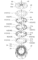
- FIG. 3 is an exploded perspective view of the bus bar unit.
- FIG. 4 is an enlarged view of a part of FIG.
- FIG. 5 is a view in which a notch is provided in the insulating paper.
- FIG. 6 is a view showing a state in which the bus bars overlap with insulating paper in plan view.
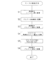
- FIG. 7 is a view showing a manufacturing process of the motor of the embodiment.
- the direction in which the central axis A of the rotor 20 extends is simply referred to as “axial direction”, the direction orthogonal to the central axis A is simply referred to as “radial direction”, and the circumference of the central axis A is simply referred to as “axial direction”. It is called “circumferential direction”.
- the upper side of FIG. 1 in the “axial direction” is simply referred to as “upper side”, and the lower side is simply referred to as “lower side”.
- the “plan view” in the present embodiment is substantially the same as the view in the axial direction when viewed in the “axial direction”. Note that the vertical direction does not indicate the positional relationship and direction when it is incorporated into an actual device.
- FIG. 1 is a cross-sectional view of a motor 100 according to the present embodiment.
- the motor 100 of the present embodiment is a brushless motor having three phases of U phase, V phase and W phase.
- the motor 100 includes a housing 10, a rotor 20, a stator 30, a pair of bearings 40, a bearing holder 50, and a bus bar unit 60.
- the housing 10 accommodates the rotor 20, the stator 30, the pair of bearings 40, the bearing holder 50, and the bus bar unit 60 in an internal space.
- the housing 10 has a cylindrical portion 11 and a bottom portion 12.
- the cylindrical portion 11 is cylindrical and extends in the axial direction along the central axis A.
- the bottom 12 is disposed at the lower end of the cylindrical portion 11.
- the bottom portion 12 has a shaft through hole 12 a and a bearing holding portion 12 b.
- the shaft through hole 12 a is provided at the center of the bottom 12.
- the bearing holder 12b is provided around the shaft through hole 12a.
- Rotor 20 The rotor 20 has a shaft 21, a rotor core 22, and a magnet 23.
- the shaft 21 extends axially along the central axis A.
- the shaft 21 is supported by a pair of bearings 40 and rotates about a central axis A.
- the pair of bearings 40 is held by the bearing holding portion 12 b of the housing 10 and the bearing holding portion 50 a of the bearing holder 50.
- the rotor core 22 is a laminated steel plate in which a plurality of electromagnetic steel plates are laminated in the axial direction.
- the rotor core 22 is fixed to a shaft 21 penetrating the center of the rotor core 22 and rotates with the shaft 21.
- the magnet 23 is fixed to the outer surface of the rotor core 22 and rotates with the rotor core 22 and the shaft 21. Therefore, the rotor 20 in the present embodiment is a rotor used for a surface permanent magnet (SPM) motor.
- the rotor 20 may be a rotor used in an IPM (Interior Permanent Magnet) motor in which the magnet 23 is embedded in the rotor core 22.
- IPM Interior Permanent Magnet
- FIG. 2 is a perspective view of the stator 30. As shown in FIG. As shown in FIG. 1 and FIG. 2, the stator 30 has a plurality of divided stator cores 31, a plurality of insulators 32, and a plurality of coils 33.
- the stator core 31 is a laminated steel plate in which a plurality of electromagnetic steel plates are laminated in the axial direction.
- the plurality of stator cores 31 are arranged in the circumferential direction, and each have a core back 31 a and teeth 31 b.
- the plurality of core backs 31 a have a cylindrical shape concentric with the central axis A.
- the teeth 31 b extend radially inward from the inner side surface of the core back 31 a. In the present embodiment, twelve teeth 31 b are provided.
- the insulator 32 is attached to each tooth 31 b and covers at least a part of the stator core 31.
- the insulator 32 is formed of, for example, an insulating resin having an insulating property.
- the coil 33 is configured by winding a conductive wire around the teeth 31 b via the insulator 32.
- the coil 33 is formed of a coil corresponding to any one of the U phase, the V phase, and the W phase, and arranged in the circumferential direction in the order of the U phase, the V phase, and the W phase.
- the number of coils 33 is twelve, which is the same as the number of teeth 31 b.
- a coil wire 34 extends upward in the axial direction.
- two coil wires 34 of a first coil wire 34a and a second coil wire 34b extend axially upward.
- the first coil wire 34a is the winding start end of the conducting wire
- the second coil wire 34b is the winding end of the conducting wire. Therefore, the total of the coil wire 34 extended from each coil 33 is 24.
- the first coil wire 34 a extends longer in the axial direction than the second coil wire 34 b.
- the bearing holder 50 is formed of, for example, a conductive metal material such as aluminum.
- the bearing holder 50 is annular as shown in FIGS. 1 and 3, and is accommodated in the housing 10 at a position above the stator 30.
- the bearing holder 50 is fixed to the bearing holder 50 so as not to move in the circumferential direction and the axial direction.
- the bearing holder 50 has a bearing holding portion 50a and a plurality of coil wire holding portions 50b.
- the bearing holder 50 a is provided around the upper end of the shaft 21 and holds one of the pair of bearings 40.
- the coil wire holding portion 50 b is a holding hole for holding the first coil wire 34 a which penetrates a penetration portion 61 b of the insulating paper 61 described later.
- the coil wire holding portion 50 b is recessed axially upward from the bottom surface of the bearing holder 50.
- the coil wire holding portion 50b is provided on the bottom surface side of the bearing holder 50 and at a position overlapping with the first coil wire 34a in a plan view.
- the coil wire holding portion 50b is provided at a position radially outward of the bearing holding portion 50a at intervals in the circumferential direction.
- the coil wire holding portion 50b is fitted with the first coil wire 34a and holds the first coil wire 34a.
- twelve coil wire holding portions 50 b equal in number to the number of first coil wires 34 a are provided in the bearing holder 50.
- the first coil wire 34a is an end portion of the winding start point of the conducting wire, and is positioned in advance. Therefore, the coil wire holding portion 50b and the first coil wire 34a can be easily fitted. Further, by holding the first coil wire 34a by the bearing holder 50, it is not necessary to provide a support member or the like for supporting the first coil wire 34a, so that the manufacturing cost of the motor 100 can be suppressed.
- FIG. 3 is an exploded perspective view of the bus bar unit 60. As shown in FIG.
- the bus bar unit 60 has a plurality of insulating papers 61, a plurality of neutral point bus bars 62, and a plurality of phase bus bars 63.
- the plurality of insulating papers 61 are arranged to overlap in the axial direction.
- five insulating papers 61 of first to fifth insulating papers 61A to 61E are arranged to overlap in the axial direction.
- the shapes of the first to fifth insulating papers 61A to 61E are identical to one another.
- Each insulating paper 61 is an annular ring concentric with the central axis A, and is a single sheet.
- the insulating paper 61 has a portion overlapping a part of all the bus bars including the neutral point bus bar 62 and the phase bus bar 63 in plan view. That is, the bus bars and the insulating paper are alternately stacked in the axial direction.
- the insulating papers 61 having the same shape can be used, so that the assembly efficiency of the motor 100 can be improved.
- the insulating paper 61 is provided at a position overlapping the coil 33 in plan view.
- the insulating paper 61 has a shaft through hole 61a and a plurality of through parts 61b as shown in an enlarged manner in FIGS. 3 and 4.
- the shaft through hole 61 a is provided to penetrate the center of the insulating paper 61 in the axial direction.
- the through portion 61 b is provided radially outward of the shaft through hole 61 a.
- the through portion 61 b is a circular through hole, and is provided at a position overlapping with the coil wire 34 in a plan view.
- the diameter of the penetrating portion 61 b is larger than the diameter of the coil wire 34, and the coil wire 34 penetrates the penetrating portion 61 b in the vertical direction one by one. Therefore, in the present embodiment, twenty-four penetration portions 61 b are provided in one insulating sheet 61.
- the positioning of the insulating paper 61 in the radial direction can be performed by the coil wire 34 penetrating the penetration portion 61 b of the insulating paper 61. Therefore, the insulating paper 61 can be positioned with a simple configuration. In addition, the shape of penetration part 61b may not be circular. Further, as shown in an enlarged manner in FIG. 5, the insulating paper 61 may be provided with a notch 61 c extending to the penetrating portion 61 b.
- the notch 61 c is, for example, a slit extending radially inward from the outer edge of the insulating paper 61 toward the penetrating portion 61 b.
- the notch 61 c may be a slit extending from the inner edge of the insulating paper 61 toward the penetrating portion 61 b.
- the neutral point bus bar 62 is disposed between two adjacent insulating papers 61.
- the two neutral point bus bars 62 of the first neutral point bus bar 62A and the second neutral point bus bar 62B are the first insulating paper 61A and the first insulating paper 61A. 2 and the insulating paper 61B.
- the first neutral point bus bar 62A and the second neutral point bus bar 62B are disposed at positions where they do not overlap each other between the first insulating paper 61A and the second insulating paper 61B in plan view in plan view It is done.
- the first neutral point bus bar 62A and the second neutral point bus bar 62B are disposed at positions facing each other with the shaft through hole 61a interposed therebetween.
- the neutral point bus bar 62 is a bare wire having a circular cross section and formed of a conductive metal material. By using the neutral point bus bar 62 having a circular cross section, it is possible to achieve both axial thinness and radial wiring space.
- the neutral point bus bar 62 has three curved portions 62 a and a connecting portion 62 b connecting the curved portions 62 a.
- the curved portions 62 a are provided alternately with the connection portions 62 b in the circumferential direction.
- the curved portion 62 a surrounds a part of the coil wire 34.
- the curved portion 62a is curved in a substantially U shape in a plan view, and is recessed radially outward.
- the curved portion 62a is electrically connected to the three first coil wires 34a corresponding to the U-phase, V-phase, and W-phase by welding or the like.
- the connecting portion 62b extends in an arc shape along the circumferential direction, and connects adjacent curved portions 62a.
- the connecting portion 62 b is disposed at a position not crossing the penetrating portion 61 b of the insulating paper 61 in plan view.
- the connecting portion 62b can be extended in the circumferential direction as compared with the case where the connecting portion 62b is made linear. Therefore, the position of the bending portion 62a is less likely to be displaced as compared with the case where the connecting portion 62b is made linear, and the position of the bending portion 62a can be easily adjusted when connecting to the first coil wire 34a.
- phase bus bar 63 is a bare wire formed of a conductive metal material having a circular cross section. By using the phase bus bar 63 having a circular cross section, it is possible to achieve both axial thinness and radial wiring space.
- Phase bus bar 63 is electrically connected to coil 33.
- the six phase bus bars 63 of the first to sixth phase bus bars 63A to 63F are provided in the bus bar unit 60.
- the first to sixth phase bus bars 63A to 63F correspond to one of the U phase, V phase and W phase, and two bus bars corresponding to each phase are provided.
- the first to sixth phase bus bars 63A to 63F are electrically connected to coil wires 34 of the same phase provided at intervals in the circumferential direction.
- the first phase bus bar 63 ⁇ / b> A includes two curved portions 63 a and a connecting portion 63 b.
- the curved portion 63 a surrounds a part of the coil wire 34.
- the curved portion 63a is substantially U-shaped in a plan view, and is recessed inward in the radial direction.
- the curved portion 63a is electrically connected to the coil wire 34 by welding or the like.
- the connecting portion 63 b extends in an arc shape along the circumferential direction, and connects the two curved portions 63 a.
- the connecting portion 63 b is disposed at a position not crossing the penetrating portion 61 b of the insulating paper 61 in plan view.
- the shapes of the second to sixth phase bus bars 63B to 63F are the same as the shape of the first phase bus bar 63A, and thus the description thereof is omitted.
- the first phase bus bar 63A and the second phase bus bar 63B are disposed, as shown in FIG. 3, at positions where they do not overlap each other in plan view between the adjacent second insulating paper 61B and third insulating paper 61C. ing. Specifically, the first phase bus bar 63A and the second phase bus bar 63B are disposed at positions facing each other in the radial direction across the shaft through hole 61a.
- the third phase bus bar 63C and the fourth phase bus bar 63D are disposed at positions where they do not overlap each other in plan view between the adjacent third insulating paper 61C and fourth insulating paper 61D, and the shaft through holes It is arrange
- the fifth phase bus bar 63E and the sixth phase bus bar 63F are disposed at positions where they do not overlap each other in plan view between the adjacent fourth insulating paper 61D and fifth insulating paper 61E, and the shaft through holes 61a Are disposed at mutually opposing positions in the radial direction.
- FIG. 6 is a diagram showing the positional relationship between the first phase bus bar 63A and the third phase bus bar 63C when the bus bar unit 60 is viewed in plan.
- the coil wire 34 which penetrates the penetration part 61b of 61 C of 3rd insulating paper is abbreviate
- the first phase bus bar 63A and the third phase bus bar 63C are arranged at positions where parts overlap each other in plan view.
- the third insulating paper 61C is disposed between the first phase bus bar 63A and the third phase bus bar 63C. That is, the portions of the first phase bus bar 63A and the third phase bus bar 63C overlapping with each other in a plan view are arranged to overlap through the third insulating paper 61C.
- an increase in axial dimension of the motor 100 can be suppressed as compared with the configuration in which a gap is provided between the first phase bus bar 63A and the third phase bus bar 63C.
- the first phase bus bar 63A and the third phase bus bar 63C in an overlapping manner in a plan view, it is possible to suppress an increase in the dimension of the motor 100 in the radial direction.
- the first neutral point bus bar 62A, the first phase bus bar 63A, the third phase bus bar 63C, and the fifth phase bus bar 63E are disposed at positions where portions thereof overlap with each other in plan view.
- the overlapping portions in the plan view are arranged to overlap through the second to fourth insulating papers 61B to 61D.
- the second neutral point bus bar 62B, the second phase bus bar 63B, the fourth phase bus bar 63D, and the sixth phase bus bar 63F are disposed at positions partially overlapping each other in plan view,
- the overlapping portions in a plan view are arranged to overlap through second to fourth insulating papers 61B to 61D.
- a fifth insulating paper 61E is disposed on the fifth phase bus bar 63E and the sixth phase bus bar 63F which are disposed at the top among the neutral point bus bars 62 and the phase bus bars 63. Specifically, the fifth insulating paper 61E is disposed between the fifth phase bus bar 63E and the sixth phase bus bar 63F and the bearing holder 50 in the axial direction. Thus, the insulation between the fifth phase bus bar 63E and the sixth phase bus bar 63F and the bearing holder 50 can be secured.
- the crossovers 64 are disposed on each of the second insulating paper 61B, the third insulating paper 61C, and the fourth insulating paper 61D.
- the crossovers 64 electrically connect the coil wires 34 of the radially opposite coils 33 of the same phase.
- the crossover 64 is electrically connected to a terminal connected to an external device (not shown).
- step S1 in a state where the coil wire 34 penetrates the through portion 61b of the insulating paper 61, the insulating paper 61 is disposed at a position overlapping at least a part of the coil 33 in the axial direction.
- the insulating paper 61 is disposed above the coil 33.
- the coil wire 34 can be easily guided to the penetrating portion 61b of the insulating paper 61 by the notch 61c.
- step S2 the neutral point bus bar 62 is disposed on the insulating paper 61.
- the neutral point bus bar 62 is disposed so as not to overlap each other in plan view.
- step S3 in a state in which the coil wire 34 penetrates the through portion 61b of the insulating paper 61, the insulating paper 61 is disposed so as to overlap the neutral point bus bar 62.
- the second insulating paper 61B is disposed so as to overlap the neutral point bus bar 62.
- step S4 the phase bus bar 63 is disposed overlapping the insulating bus bar 61 at a position where the phase bus bar 63 overlaps at least a part of the neutral point bus bar 62 in plan view.
- the first phase bus bar 63A and the second phase bus bar 63A It arrange
- step S5 the same steps as step S3 and step S4 are alternately repeated.
- the third insulating paper 61C is disposed so as to overlap the first phase bus bar 63A and the second phase bus bar 63B in a state in which the coil wire 34 penetrates the through portion 61b of the third insulating paper 61C.
- the third phase bus bar 63C is disposed to overlap the third phase bus bar 63C at a position where the third phase bus bar 63C overlaps at least a part of the first phase bus bar 63A in plan view via the third insulating paper 61C.
- the fourth phase bus bar 63D is disposed to overlap the fourth phase bus bar 63D at a position where it overlaps at least a part of the second phase bus bar 63B in plan view, with the third insulating paper 61C interposed therebetween.
- the fourth insulating paper 61D is disposed so as to overlap the third phase bus bar 63C and the fourth phase bus bar 63D.
- the fifth phase bus bar 63E is disposed so as to be overlapped via the fourth insulating paper 61D at a position where the fifth phase bus bar 63E overlaps at least a part of the third phase bus bar 63C in plan view.
- the sixth phase bus bar 63F is disposed so as to be overlapped via the fourth insulating paper 61D at a position where the sixth phase bus bar 63F overlaps with at least a part of the fourth phase bus bar 63D in a plan view.
- the insulating paper 61 is disposed on the bus bar arranged at the highest position among the neutral point bus bars 62 and the phase bus bars 63.
- the fifth insulating paper 61E is disposed so as to overlap the fifth phase bus bar 63E and the sixth phase bus bar 63F in a state where the coil wire 34 penetrates the through portion 61b of the fifth insulating paper 61E.
- step S1 may be omitted.
- the neutral point bus bar 62 or the phase bus bar 63 is not the insulating paper 61, but a support member for supporting the coil wire 34 formed of an insulating material such as resin. Will be placed.
- step S5 for example, when the bearing holder 50 is formed of an insulating material such as a resin, step S6 may be omitted.
- the electrical connection between the neutral point bus bar 62 or the phase bus bar 63 and the coil wire 34 may be performed collectively after the process of S6, but separately after the process of step S2 or step S4. May be The electrical connection between the neutral point bus bar 62 or the phase bus bar 63 and the coil wire 34 is performed by welding, caulking, or the like, but may be performed by another method.
- the dimension in the axial direction of the motor 100 is increased compared to the configuration in which a gap is provided in the axial direction between the first phase bus bar 63A and the third phase bus bar 63C. Can be reduced. Further, by using the insulating paper 61, the assembly of the motor 100 can be simplified, and the manufacturing cost of the motor 100 can be suppressed. Moreover, the insulation of the neutral point bus bar 62 and the phase bus bar 63 can be secured with a simple configuration.
- the neutral point bus bar 62 and the phase bus bar 63 have a circular cross section, but a rectangular wire having a rectangular cross section may be used.
- the neutral point bus bar 62 and the phase bus bar 63 may be plate-like members.
- a wire rod subjected to an insulation treatment may be used for the neutral point bus bar 62 and the phase bus bar 63.
- the present invention is applied to the bus bar including the neutral point bus bar 62 and the phase bus bar 63 in the embodiment, the present invention is applied to only the neutral point bus bar 62 or only the phase bus bar 63. It is also good.
- the insulating paper 61 is a single sheet, but one insulating paper 61 may be divided into a plurality of pieces. In addition, the insulating paper 61 may be partially provided in a portion where the bus bars overlap with each other in plan view, instead of one sheet. Further, in the case where a plurality of insulating papers 61 are provided, insulating papers having different shapes of the plurality of insulating papers may be used.
- the five busbar units 60 are provided with the five insulating papers 61. However, it is not necessary to provide a plurality of the insulating papers 61. Depending on the configuration of the motor 100, at least one insulating sheet 61 may be disposed in a portion where the bus bars overlap with each other in a plan view.
- all the coil wires 34 vertically penetrate the penetrating portion 61b of the insulating paper 61.
- the portion of the second coil wire 34b overlapping the insulating paper 61 is the axial direction
- only the first coil wire 34 a may be penetrated through the penetration portion 61 b of the insulating paper 61.
- the same number of penetrating portions 61b of the insulating paper 61 as the first coil wires 34a may be provided.
- the rotor core 22 and the stator core 31 were comprised with the laminated steel plate which the some electromagnetic steel plate was laminated
- the rotor core 22 and the stator core 31 may be constituted by, for example, a dust core.
- a plurality of the insulating sheets are arranged in an axial direction, and at least two of the plurality of bus bars are adjacent to each other among the plurality of insulating sheets. Are disposed at mutually different positions in the axial direction.
- the bus bar and the insulating paper are alternately stacked in the axial direction.
- the penetration portion is a hole or a notch.
- the motor according to an exemplary embodiment of the present invention is another motor disposed on at least one of the bus bar disposed uppermost in the bus bar and at least one bus disposed lowermost in the bus bar. It further comprises an insulating paper.
- the motor of an exemplary embodiment of the present invention includes a plurality of the insulating papers, and the shapes of the respective insulating papers are identical to each other.
- the insulating paper is a single sheet having a portion overlapping with a part of all the bus bars in an axial direction.
- the bus bar has at least one curved portion surrounding a portion of a coil wire extending from the coil in an axial view.
- the bus bar includes a plurality of the curved portions and a connecting portion that connects the plurality of the curved portions, and the connecting portion is viewed in an axial direction. It is arranged in an arc shape.
- the connecting portions of the bus bars are located different from the penetrating portions in plan view.
- the bus bar is circular in cross section.
- the rotor further includes a shaft that rotates around the rotation axis, and a housing that accommodates the rotor and the stator, and a position above the stator.
- the apparatus further comprises a bearing for supporting the shaft, and a bearing holder housed in the housing at a position above the stator and holding the bearing, the stator being disposed radially outward of the rotor
- the bearing holder has a coil wire holding portion, and the coil wire holding portion holds the coil wire penetrating the penetration portion.
- a method of manufacturing a motor includes: a plurality of bus bars electrically connected to a coil provided in a stator; and at least one insulating sheet having a penetrating portion axially penetrating
- the first step of arranging at least one first bus bar of the plurality of bus bars, and in a state in which the coil wire extending from the coil penetrates the penetrating portion of the insulating paper A second step of arranging the second bus bar on the first bus bar and the at least one second bus bar of the plurality of bus bars at a position at least partially overlapping the first bus bar in the axial direction view
- a third step of arranging them in an overlapping manner through insulating paper In the first step of arranging at least one first bus bar of the plurality of bus bars, and in a state in which the coil wire extending from the coil penetrates the penetrating portion of the insulating paper, A second step of arranging the second bus bar on the first bus bar and the at least one second bus bar of the plurality of bus bars
- a step of disposing the insulating paper in a state where the coil wire penetrates the penetrating portion of the insulating paper before the first step or After the third step, there is provided at least one of the step of arranging the insulating paper so as to overlap the second bus bar in a state where the coil wire penetrates the penetrating portion of the insulating paper.
- a plurality of the insulating papers are disposed so as to overlap in the axial direction, and at least one of the first bus bar and the second bus bar has the plurality of insulations.
- a plurality of bus bars are arranged at mutually different positions in the axial direction between two adjacent insulating sheets of paper.
- the penetration portion is a hole or a notch.
- a method of manufacturing a motor according to an exemplary embodiment of the present invention includes a plurality of the insulating papers, and the shapes of the insulating papers are identical to each other.
Landscapes
- Engineering & Computer Science (AREA)
- Power Engineering (AREA)
- Manufacturing & Machinery (AREA)
- Insulation, Fastening Of Motor, Generator Windings (AREA)
- Manufacture Of Motors, Generators (AREA)
Abstract
【課題】 モータにおいて、モータの寸法の増大を抑えると共に、簡単な構成でバスバー同士の絶縁性を確保することにある。 【解決手段】 モータ100は、上下に伸びる回転軸を有するロータ20と、複数のコイル33を有するステータ30と、コイル33と電気的に接続される複数のバスバー62,63と、貫通部61bを有する少なくとも1つの絶縁紙61と、を備えている。複数のバスバー62,63のうち少なくとも2つのバスバーは、軸方向視において、一部が互いに重なる位置に配置され、絶縁紙61の貫通部61bは、コイル33から延びるコイル線34が上下方向に貫通し、絶縁紙61は、バスバー62,63が重なる位置においてバスバー62,63の間に配置される。
Description
本発明は、モータ、及びモータの製造方法に関する。
モータには、複数のバスバーを備えたモータがある。複数のバスバーは、複数の導電線の端部を電気的に接続するために用いられる。異なる相のバスバー同士は、互いに接触しないことにより絶縁性が確保されている。バスバー間に空隙を設けてバスバー同士の絶縁性を確保する構成が、例えば、特許文献1に記載されている。また、例えば特許文献2に記載されているように、従来では、絶縁シートとバスバーとを接着させることで、異なる相のバスバー同士の絶縁性を確保する構成も提案されている。
バスバー間に空隙を設ける構成では、空隙の寸法が大きいため、モータの軸方向又は径方向の寸法が大きくなる。また、特許文献2に記載の構成では、治具に設けられた位置決め部材によって、絶縁シートの位置決めをしているため、治具のコストが高くなる。また、絶縁シートを治具で位置決めした後に、絶縁シートとバスバーとを接着させる必要があり、簡単な構成でバスバー同士の絶縁性を確保することが難しい。
本発明の課題は、モータにおいて、モータの寸法の増大を抑えると共に、簡単な構成でバスバー同士の絶縁性を確保することにある。
本発明の例示的な一実施形態に係るモータは、上下に伸びる回転軸を有するロータと、複数のコイルを有するステータと、コイルと電気的に接続される複数のバスバーと、貫通部を有する少なくとも1つの絶縁紙と、を備えている。複数のバスバーのうち少なくとも2つのバスバーは、軸方向視において、一部が互いに重なる位置に配置され、絶縁紙の貫通部は、コイルから延びるコイル線が上下方向に貫通し、絶縁紙は、バスバーが重なる位置においてバスバーの間に配置される。
本発明に係る例示的な一実施形態によれば、絶縁紙を使用することにより、モータの寸法の増大を抑えることができる。また、コイル線が絶縁紙の貫通部を貫通することで絶縁紙が位置決めされるため、簡単な構成でバスバー同士の絶縁性を確保することができる。
以下、図面に基づいて本発明の実施形態を説明する。なお、以下の説明で用いる図面は、特徴部分を強調する目的で、便宜上特徴となる部分を拡大して示している場合がある。したがって、各構成要素の寸法比率などが実際と同じであるとは限らない。また、同様の目的で、特徴とならない部分を省略して図示する場合がある。
また、以下の説明において、ロータ20の中心軸Aが延びる方向を単に「軸方向」と呼び、中心軸Aと直交する方向を単に「径方向」と呼び、中心軸Aの軸周りを単に「周方向」と呼ぶ。また、「軸方向」における図1の上側を単に「上側」と呼び、下側を単に「下側」と呼ぶ。また、本実施形態における「平面視」とは、実質的に「軸方向」から視たとき、すなわち、軸方向視と同じである。なお、上下方向は、実際の機器に組み込まれたときの位置関係および方向を示すものではない。
図1は、本実施形態のモータ100の断面図である。本実施形態のモータ100は、U相、V相、W相の3つの相を有するブラシレスモータである。モータ100は、ハウジング10と、ロータ20と、ステータ30と、1対のベアリング40と、ベアリングホルダ50と、バスバーユニット60と、を備える。
[ハウジング10] ハウジング10は、ロータ20、ステータ30、1対のベアリング40、ベアリングホルダ50、及びバスバーユニット60を内部空間に収容する。ハウジング10は、円筒部11と、底部12と、を有する。円筒部11は、筒状であり、中心軸Aに沿って軸方向に延びる。底部12は、円筒部11の下端部に配置される。底部12は、シャフト貫通孔12aと、ベアリング保持部12bと、を有する。シャフト貫通孔12aは、底部12の中央に設けられる。ベアリング保持部12bは、シャフト貫通孔12aの周囲に設けられる。
[ロータ20] ロータ20は、シャフト21と、ロータコア22と、マグネット23と、を有する。 シャフト21は、中心軸Aに沿って軸方向に延びる。シャフト21は、1対のベアリング40に支持され、中心軸Aを中心に回転する。1対のベアリング40は、ハウジング10のベアリング保持部12bと、ベアリングホルダ50のベアリング保持部50aとに保持される。
ロータコア22は、複数の電磁鋼板が軸方向に積層された積層鋼板である。ロータコア22は、ロータコア22の中心を貫通するシャフト21に固定され、シャフト21とともに回転する。マグネット23は、ロータコア22の外側面に固定され、ロータコア22及びシャフト21とともに回転する。したがって、本実施形態でのロータ20は、SPM(Surface Permanent Magnet)モータに用いられるロータである。なお、ロータ20は、マグネット23がロータコア22の内部に埋め込まれたIPM(Interior Permanent Magnet)モータに用いられるロータであってもよい。
[ステータ30] ステータ30は、ロータ20の径方向外側を囲む。図2は、ステータ30の斜視図である。図1及び図2に示すように、ステータ30は、分割された複数のステータコア31と、複数のインシュレータ32と、複数のコイル33と、を有する。
ステータコア31は、複数の電磁鋼板が軸方向に積層された積層鋼板である。複数のステータコア31は、周方向に並べて配置されており、それぞれ、コアバック31aと、ティース31bと、を有する。複数のコアバック31aは、中心軸Aと同心の円筒状である。ティース31bは、コアバック31aの内側面から径方向内側に延びている。本実施形態では、12個のティース31bが設けられる。
インシュレータ32は、各ティース31bに装着され、ステータコア31の少なくとも一部を覆う。インシュレータ32は、絶縁性を有する、例えば絶縁性の樹脂で形成される。
コイル33は、インシュレータ32を介して導線がティース31bに巻き付けられて構成される。コイル33は、U相、V相、及びW相のいずれかの相に対応するコイルで構成され、U相、V相、及びW相の順に周方向に並んで配置される。コイル33の数は、ティース31bの数と同じ12個である。
図2に示すように、各コイル33からは、コイル線34が軸方向上側に向かって延びている。詳細には、各コイル33からは、第1コイル線34aおよび第2コイル線34bの2本のコイル線34が軸方向上側に向かって延びている。第1コイル線34aは、導線の巻き始めの端部であり、第2コイル線34bは、導線の巻き終わりの端部である。したがって、各コイル33から延びるコイル線34の合計は24本である。本実施形態では、第1コイル線34aが第2コイル線34bよりも軸方向上側に長く延びている。
[ベアリングホルダ50] ベアリングホルダ50は、例えばアルミ等の導電性を有する金属材料で形成されている。ベアリングホルダ50は、図1及び図3に示すように、環状であり、ステータ30よりも上側の位置でハウジング10に収容されている。また、ベアリングホルダ50は、周方向および軸方向に移動不能にベアリングホルダ50に固定されている。
ベアリングホルダ50は、ベアリング保持部50aと、複数のコイル線保持部50bと、を有する。ベアリング保持部50aは、シャフト21の上端部の周囲に設けられ、1対のベアリング40の一方を保持する。コイル線保持部50bは、後述する絶縁紙61の貫通部61bを貫通する第1コイル線34aを保持するための保持穴である。コイル線保持部50bは、ベアリングホルダ50の底面から軸方向上側に凹む。コイル線保持部50bは、ベアリングホルダ50の底面側、かつ平面視において、第1コイル線34aと重なる位置設けられている。コイル線保持部50bは、ベアリング保持部50aよりも径方向外側の位置に、周方向に間隔を隔てて設けられている。
コイル線保持部50bは、第1コイル線34aが嵌まり、第1コイル線34aを保持する。本実施形態では、第1コイル線34aの個数と同数の12個のコイル線保持部50bがベアリングホルダ50に設けられている。第1コイル線34aは、導線の巻き始めの端部であり、予め位置決めされているため、コイル線保持部50bと第1コイル線34aとを容易に嵌め合わすことができる。また、ベアリングホルダ50によって、第1コイル線34aを保持することで、第1コイル線34aを支持するための支持部材等を設ける必要がなくなるため、モータ100の製造コストを抑えることができる。
[バスバーユニット60] 図3は、バスバーユニット60の分解斜視図である。バスバーユニット60は、複数の絶縁紙61と、複数の中性点用バスバー62と、複数の相用バスバー63と、を有している。
[絶縁紙61] 複数の絶縁紙61は、軸方向に重ねて配置されている。本実施形態では、第1~第5絶縁紙61A~61Eの5枚の絶縁紙61が、軸方向に重ねて配置されている。第1~第5絶縁紙61A~61Eの各々の形状は、互いに同一である。各絶縁紙61は、中心軸Aと同心の円環状であり、1枚紙である。絶縁紙61は、平面視において、中性点用バスバー62及び相用バスバー63を含む全てのバスバーの一部と重なる部分を有する。すなわち、バスバーおよび絶縁紙は、軸方向に交互に重ねて配置されている。これにより、複数の絶縁紙61を軸方向に重ねて配置する際に、同じ形状の絶縁紙61を使用することができるため、モータ100の組み立て効率を改善することができる。
絶縁紙61は、平面視において、コイル33と重なる位置に設けられる。絶縁紙61は、図3及び図4に拡大して示すように、シャフト貫通孔61aと、複数の貫通部61bと、を有する。シャフト貫通孔61aは、絶縁紙61の中央を軸方向に貫通して設けられる。貫通部61bは、シャフト貫通孔61aよりも径方向外側に設けられる。貫通部61bは、円形の貫通孔であり、平面視において、コイル線34と重なる位置に設けられている。貫通部61bの直径は、コイル線34の線径よりも大径であり、貫通部61bをコイル線34が1本ずつ上下方向に貫通する。したがって、本実施形態では、24個の貫通部61bが1枚の絶縁紙61に設けられている。
ここでは、絶縁紙61の貫通部61bを貫通するコイル線34によって絶縁紙61の径方向の位置決めができる。このため、簡単な構成で絶縁紙61の位置決めができる。なお、貫通部61bの形状は円形でなくてもよい。また、図5に拡大して示すように、絶縁紙61に貫通部61bまで延びる切り欠き61cを設けてもよい。切り欠き61cは、例えば、絶縁紙61の外縁から貫通部61bに向かって径方向内側に延びるスリットである。これにより、絶縁紙61の貫通部61bにコイル線34を通すときに、絶縁紙61又はコイル線34の位置にずれがあった場合でも、切り欠き61cによって絶縁紙61の貫通部61bにコイル線34を容易に案内することができる。なお、切り欠き61cは、絶縁紙61の内縁から貫通部61bに向かって延びるスリットであってもよい。
[中性点用バスバー62] 中性点用バスバー62は、隣接する2枚の絶縁紙61の間に配置されている。本実施形態では、図4に拡大して示すように、第1中性点用バスバー62A及び第2中性点用バスバー62Bの2つの中性点用バスバー62が、第1絶縁紙61Aと第2絶縁紙61Bとの間に配置されている。第1中性点用バスバー62Aと第2中性点用バスバー62Bとは、平面視において、平面視において、第1絶縁紙61Aと第2絶縁紙61Bとの間で、互いに重ならない位置に配置されている。詳細には、第1中性点用バスバー62Aと第2中性点用バスバー62Bとは、シャフト貫通孔61aを挟んで互いに対向する位置に配置されている。
中性点用バスバー62は、断面が円形状であり、導電性を有する金属材料で形成された裸線である。断面が円形状の中性点用バスバー62を用いることで、軸方向の薄さと、径方向の配線スペースとを両立させることができる。中性点用バスバー62は、3つの湾曲部62aと、湾曲部62aを連結する連結部62bと、を有する。
湾曲部62aは、連結部62bと周方向に交互に並んで設けられる。湾曲部62aは、コイル線34の一部を囲む。詳細には、湾曲部62aは、平面視において、略U字状に湾曲し、径方向外側に向かって凹む。湾曲部62aは、U相、V相、W相の各相に対応する3つの第1コイル線34aと溶接等により電気的に接続される。湾曲部62aを設けることで、中性点用バスバー62と第1コイル線34aとの接触面積が大きくなり、接触抵抗を低減させることができる。また、中性点用バスバー62と第1コイル線34aとの接続が強固になる。
連結部62bは、周方向に沿って円弧状に延び、隣接する湾曲部62a同士を接続する。連結部62bは、平面視において、絶縁紙61の貫通部61bを横切らない位置に配置される。連結部62bを円弧状にすることにより、連結部62bを直線状にした時と比べて、連結部62bは周方向に延びることができる。そのため、連結部62bを直線状にした時と比べて、湾曲部62aの位置がずれにくくなるとともに、第1コイル線34aと接続する際に、湾曲部62aの位置の調整がしやすくなる。
[相用バスバー63] 相用バスバー63は、断面が円形状であり、導電性を有する金属材料で形成された裸線である。断面が円形状の相用バスバー63を用いることで、軸方向の薄さと、径方向の配線スペースとを両立させることができる。相用バスバー63は、コイル33と電気的に接続される。本実施形態では、図3に示すように、第1~第6相用バスバー63A~63Fの6つの相用バスバー63が、バスバーユニット60に設けられている。第1~第6相用バスバー63A~63Fは、U相、V相、及びW相のいずれかの相に対応しており、各相に対応するバスバーが2つずつ設けられる。第1~第6相用バスバー63A~63Fは、周方向に間隔を隔てて設けられた同じ相のコイル線34と電気的に接続される。
第1相用バスバー63Aは、図4に示すように、2つの湾曲部63aと、連結部63bと、を有する。湾曲部63aは、コイル線34の一部を囲む。詳細には、湾曲部63aは、平面視において、略U字状であり、径方向内側に向かって凹む。湾曲部63aは、溶接等によりコイル線34と電気的に接続される。湾曲部63aを設けることで、第1相用バスバー63Aとコイル線34との接触面積が大きくなり、接触抵抗を低減させることができる。また、第1相用バスバー63Aとコイル線34との接続が強固になる。
連結部63bは、周方向に沿って円弧状に延び、2つの湾曲部63aを連結する。連結部63bは、平面視において、絶縁紙61の貫通部61bを横切らない位置に配置される。なお、第2~第6相用バスバー63B~63Fの形状は、第1相用バスバー63Aの形状と同様であるため、説明を省略する。
第1相用バスバー63A及び第2相用バスバー63Bは、図3に示すように、隣接する第2絶縁紙61Bと第3絶縁紙61Cとの間で、平面視で互いに重ならない位置に配置されている。詳細には、第1相用バスバー63Aと第2相用バスバー63Bとは、シャフト貫通孔61aを挟んで径方向において互いに対向する位置に配置されている。同様に、第3相用バスバー63C及び第4相用バスバー63Dは、隣接する第3絶縁紙61Cと第4絶縁紙61Dとの間で、平面視で互いに重ならない位置に配置され、シャフト貫通孔61aを挟んで径方向において互いに対向する位置に配置されている。また、第5相用バスバー63E及び第6相用バスバー63Fは、隣接する第4絶縁紙61Dと第5絶縁紙61Eとの間で、平面視で互いに重ならない位置に配置され、シャフト貫通孔61aを挟んで径方向において互いに対向する位置に配置されている。
このように、中性点用バスバー62及び相用バスバー63のうち、少なくとも2つのバスバーを、隣接する2枚の絶縁紙61の間で、平面視で互いに重ならない位置に配置することで、隣接する2枚の絶縁紙61の間に1つのバスバーを配置したときよりも、モータ100の軸方向の寸法の増大を抑えることができる。
また、中性点用バスバー62及び相用バスバー63のうち、少なくとも2つのバスバーは、平面視で一部が互いに重なる位置に配置されている。例えば、図6は、バスバーユニット60を平面視したときの、第1相用バスバー63A及び第3相用バスバー63Cの位置関係を示した図である。なお、図6では、第3絶縁紙61Cの貫通部61bを貫通するコイル線34を省略して示している。
第1相用バスバー63A及び第3相用バスバー63Cは、図6に示すように、平面視で一部が互いに重なる位置に配置されている。この第1相用バスバー63Aと第3相用バスバー63Cとが重なる位置において、第1相用バスバー63Aと第3相用バスバー63Cとの間に第3絶縁紙61Cが配置されている。すなわち、第1相用バスバー63Aと第3相用バスバー63Cとは、平面視で互いに重なる部分が、第3絶縁紙61Cを介して重ねて配置されている。これにより、第1相用バスバー63Aと第3相用バスバー63Cとの間に空隙を設けた構成よりも、モータ100の軸方向の寸法の増大を抑えることができる。また、第1相用バスバー63Aと第3相用バスバー63Cとを平面視で重ねて配置することで、モータ100の径方向の寸法の増大も抑えることができる。
なお、本実施形態では、第1中性点用バスバー62A、第1相用バスバー63A、第3相用バスバー63C、及び第5相用バスバー63Eは、一部が互いに平面視で重なる位置に配置されており、平面視で重なる部分が第2~第4絶縁紙61B~61Dを介して重ねて配置されている。同様に、第2中性点用バスバー62B、第2相用バスバー63B、第4相用バスバー63D、及び第6相用バスバー63Fは、一部が互いに平面視で重なる位置に配置されており、平面視で重なる部分が第2~第4絶縁紙61B~61Dを介して重ねて配置されている。
中性点用バスバー62及び相用バスバー63のうち、最も上方に配置された第5相用バスバー63E及び第6相用バスバー63Fの上には、第5絶縁紙61Eが配置されている。詳細には、第5相用バスバー63E及び第6相用バスバー63Fと、ベアリングホルダ50との軸方向の間に第5絶縁紙61Eが配置されている。これにより、第5相用バスバー63E及び第6相用バスバー63Fと、ベアリングホルダ50との絶縁性を確保することができる。
なお、本実施形態では、第2絶縁紙61B、第3絶縁紙61C、及び第4絶縁紙61Dの各々に、渡り線64が配置されている。渡り線64は、径方向に対向する同じ相のコイル33のコイル線34を電気的に接続する。また、渡り線64は、図示しない外部装置に接続される端子と電気的に接続される。
[製造方法] 次に、図7を参照して、本実施形態に係るモータ100、特にバスバーユニット60の製造方法の一例を説明する。なお、バスバーユニット以外のモータ100の製造方法については従来と同様であるため、説明を省略する。
ステップS1で、絶縁紙61の貫通部61bにコイル線34を貫通させた状態で、軸方向視において、コイル33の少なくとも一部に重なる位置に絶縁紙61を配置する。本実施形態では、コイル33の上部に絶縁紙61を配置する。このとき、絶縁紙61が、切り欠き61cを有する場合は、切り欠き61cによって絶縁紙61の貫通部61bにコイル線34を容易に案内することができる。
ステップS2で、絶縁紙61に中性点用バスバー62を配置する。このとき、例えば少なくとも2つの中性点用バスバー62を絶縁紙61に配置する場合は、互いに平面視で重ならない状態で配置する。
ステップS3で、絶縁紙61の貫通部61bにコイル線34を貫通させた状態で、絶縁紙61を中性点用バスバー62に重ねて配置する。本実施形態では、第2絶縁紙61Bを中性点用バスバー62に重ねて配置する。
ステップS4で、相用バスバー63を、相用バスバー63が平面視で中性点用バスバー62の少なくとも一部に重なる位置に、絶縁紙61を介して重ねて配置する。本実施形態のように第1相用バスバー63A及び第2相用バスバー63Bの少なくとも2つの相用バスバー63を第2絶縁紙61Bに配置する場合は、第1相用バスバー63Aと第2相用バスバー63Bとが平面視で重ならない状態で配置する。
ステップS5で、ステップS3およびステップS4と同様の工程を交互に繰り返し行う。本実施形態では、第3絶縁紙61Cの貫通部61bにコイル線34を貫通させた状態で、第3絶縁紙61Cを第1相用バスバー63A及び第2相用バスバー63Bに重ねて配置する。そして、第3相用バスバー63Cを、第3相用バスバー63Cが平面視で第1相用バスバー63Aの少なくとも一部に重なる位置に、第3絶縁紙61Cを介して重ねて配置する。同様に、第4相用バスバー63Dを、第4相用バスバー63Dが平面視で第2相用バスバー63Bの少なくとも一部に重なる位置に、第3絶縁紙61Cを介して重ねて配置する。
その後、第4絶縁紙61Dの貫通部61bにコイル線34を貫通させた状態で、第4絶縁紙61Dを第3相用バスバー63Cおよび第4相用バスバー63Dに重ねて配置する。そして、第5相用バスバー63Eを、第5相用バスバー63Eが平面視で第3相用バスバー63Cの少なくとも一部に重なる位置に、第4絶縁紙61Dを介して重ねて配置する。同様に、第6相用バスバー63Fを、第6相用バスバー63Fが平面視で第4相用バスバー63Dの少なくとも一部に重なる位置に、第4絶縁紙61Dを介して重ねて配置する。
ステップS6で、中性点用バスバー62及び相用バスバー63のうち、最も上方に配置されたバスバーの上に絶縁紙61を配置する。本実施形態では、第5絶縁紙61Eの貫通部61bにコイル線34を貫通させた状態で、第5絶縁紙61Eを第5相用バスバー63E及び第6相用バスバー63Fに重ねて配置する。
なお、ステップS1において、他の部材等によって中性点用バスバー62又は相用バスバー63の絶縁性が確保されている状態であればステップS1を省略してもよい。この場合、例えばステップS2において、中性点用バスバー62又は相用バスバー63は、絶縁紙61ではなく、樹脂等の絶縁性を有する材料で形成されたコイル線34を支持するための支持部材等に配置される。同様に、ステップS5において、例えば、ベアリングホルダ50が樹脂等の絶縁性を有する材料で形成されている場合は、ステップS6を省略してもよい。また、中性点用バスバー62又は相用バスバー63とコイル線34との電気的な接続は、S6の工程の後にまとめて行ってもよいが、ステップS2又はステップS4の工程の後に個別に行ってもよい。なお、中性点用バスバー62又は相用バスバー63とコイル線34との電気的な接続は、溶接又はかしめ等により行っているが、その他の方法により行ってもよい。
上記のモータ100の製造方法によれば、例えば、第1相用バスバー63Aと第3相用バスバー63Cとの間に軸方向に空隙を設けた構成よりも、モータ100の軸方向の寸法の増大を抑えることができる。また、絶縁紙61を使用することにより、モータ100の組み立てが簡易にすることができ、モータ100の製造コストを抑えることができる。また、簡単な構成で中性点用バスバー62及び相用バスバー63の絶縁性を確保することができる。
<他の実施形態> 本発明は以上のような実施形態に限定されるものではなく、実施形態における各構成およびそれらの組み合わせ等は一例であり、本発明の趣旨から逸脱しない範囲内で、構成の付加、省略、置換およびその他の変更が可能である。
前記実施形態では、中性点用バスバー62および相用バスバー63は、断面が円形状であったが、断面矩形状の平角線を用いてもよい。また、中性点用バスバー62及び相用バスバー63は、板状の部材であってもよい。また、中性点用バスバー62および相用バスバー63に、絶縁処理された線材を用いてもよい。
前記実施形態では、中性点用バスバー62および相用バスバー63を含むバスバーに本願発明を適用していたが、中性点用バスバー62のみ、若しくは相用バスバー63のみに本願発明を適用してもよい。
前記実施形態では、絶縁紙61は1枚紙であったが、1枚の絶縁紙61を複数に分割して用いてもよい。また、絶縁紙61を1枚紙ではなく、平面視でバスバー同士の一部が互いに重なる部分に部分的に設けてもよい。また、複数の絶縁紙61を設ける場合において、複数の絶縁紙の各々の形状が異なる絶縁紙を用いてもよい。
前記実施形態では、バスバーユニット60に5枚の絶縁紙61を設けていたが、絶縁紙61を必ずしも複数設ける必要はない。モータ100の構成によっては、少なくとも1枚の絶縁紙61が、平面視でバスバー同士の一部が互いに重なる部分に配置されていればよい。
前記実施形態では、全てのコイル線34が絶縁紙61の貫通部61bを上下方向に貫通していたが、例えば、平面視で、第2コイル線34bの絶縁紙61に重なる部分が、軸方向上側に延びていない構成のモータであれば、第1コイル線34aのみを絶縁紙61の貫通部61bに貫通させてもよい。この場合、絶縁紙61の貫通部61bは、第1コイル線34aと同じ数だけ設ければよい。
前記実施形態では、ロータコア22およびステータコア31は、複数の電磁鋼板が軸方向に積層された積層鋼板で構成していたが、これに限定されるものではない。ロータコア22およびステータコア31を、例えば、圧粉磁心によって構成してもよい。
本発明の例示的な一実施形態のモータは、前記絶縁紙は、軸方向に複数重ねて配置され、前記複数のバスバーのうち少なくとも2つのバスバーが、前記複数の絶縁紙のうち隣接する2枚の絶縁紙の間で、軸方向に互いに異なる位置に配置されている。
本発明の例示的な一実施形態のモータは、前記バスバーおよび前記絶縁紙は、軸方向に交互に重ねて配置されている。
本発明の例示的な一実施形態のモータは、前記貫通部は孔又は切り欠きである。
本発明の例示的な一実施形態のモータは、前記バスバーのうち最も上方に配置されたバスバーの上、および、前記バスバーのうち最も下方に配置されたバスバーの下の少なくとも一方に配置された別の絶縁紙をさらに備える。
本発明の例示的な一実施形態のモータは、前記絶縁紙を複数有し、前記絶縁紙の各々の形状は、互いに同一である。
本発明の例示的な一実施形態のモータは、前記絶縁紙は、軸方向視において、全ての前記バスバーの一部と重なる部分を有する1枚紙である。
本発明の例示的な一実施形態のモータは、前記バスバーは、軸方向視において、前記コイルから延びるコイル線の一部を囲む少なくとも1つの湾曲部を有する。
本発明の例示的な一実施形態のモータは、前記バスバーは、複数の前記湾曲部と、前記複数の前記湾曲部を連結する連結部と、を有し、前記連結部は、軸方向視において円弧状に配置されている。
本発明の例示的な一実施形態のモータは、前記バスバーの前記連結部は、平面視において、前記貫通部と互いに異なって位置する。
本発明の例示的な一実施形態のモータは、前記バスバーは断面が円形状である。
本発明の例示的な一実施形態のモータは、前記ロータは、前記回転軸を中心に回転するシャフトをさらに有し、前記ロータ及び前記ステータを収容するハウジングと、前記ステータよりも上側の位置で前記シャフトを支持するベアリングと、前記ステータよりも上側の位置で前記ハウジングに収容され、前記ベアリングを保持するベアリングホルダと、をさらに備え、前記ステータは、前記ロータの径方向外側に配置されており、前記ベアリングホルダは、コイル線保持部を有し、前記コイル線保持部は、前記貫通部を貫通する前記コイル線を保持する。
本発明の例示的な一実施形態のモータの製造方法は、ステータに設けられたコイルと電気的に接続される複数のバスバーと、軸方向に貫通する貫通部を有する少なくとも1枚の絶縁紙と、を有し、前記複数のバスバーのうち少なくとも1つの第1のバスバーを配置する第1の工程と、前記絶縁紙の前記貫通部に前記コイルから延びるコイル線が貫通した状態で、前記絶縁紙を前記第1のバスバーに重ねて配置する第2の工程と、前記複数のバスバーのうち少なくとも1つの第2のバスバーを、軸方向視において、前記第1のバスバーと少なくとも一部重なる位置に前記絶縁紙を介して重ねて配置する第3の工程と、を備える。
本発明の例示的な一実施形態のモータの製造方法は、前記第1の工程の前に、前記絶縁紙の貫通部に前記コイル線が貫通した状態で、前記絶縁紙を配置する工程、又は、前記第3の工程の後に、前記絶縁紙の貫通部に前記コイル線が貫通した状態で、前記絶縁紙を前記第2のバスバーに重ねて配置する工程の少なくとも一方を備える。
本発明の例示的な一実施形態のモータの製造方法は、前記絶縁紙は、軸方向に複数重ねて配置され、前記第1のバスバーと前記第2のバスバーの少なくとも一方は、前記複数の絶縁紙のうち隣接する2枚の絶縁紙の間で、軸方向に互いに異なる位置で配置される複数のバスバーである。
本発明の例示的な一実施形態のモータの製造方法は、前記貫通部は孔又は切り欠きである。
本発明の例示的な一実施形態のモータの製造方法は、複数の前記絶縁紙を有し、前記絶縁紙の各々の形状は、互いに同一である。
Claims (17)
- 上下に延びる回転軸を有するロータと、
複数のコイルを有するステータと、
前記コイルと電気的に接続される複数のバスバーと、
貫通部を有する少なくとも1つの絶縁紙と、を備えたモータであって、
前記複数のバスバーのうち少なくとも2つのバスバーは、軸方向視において、一部が互いに重なる位置に配置され、
前記絶縁紙の前記貫通部は、前記コイルから延びるコイル線が上下方向に貫通し、
前記絶縁紙は、前記バスバーが重なる位置において前記バスバーの間に配置される、モータ。 - 前記絶縁紙は、軸方向に複数重ねて配置され、
前記複数のバスバーのうち少なくとも2つのバスバーが、前記複数の絶縁紙のうち隣接する2枚の絶縁紙の間で、軸方向に互いに異なる位置に配置されている、請求項1に記載のモータ。 - 前記バスバーおよび前記絶縁紙は、軸方向に交互に重ねて配置されている、請求項1又は2に記載のモータ。
- 前記貫通部は孔又は切り欠きである、請求項1から3のいずれか1項に記載のモータ。
- 前記バスバーのうち最も上方に配置されたバスバーの上、および、前記バスバーのうち最も下方に配置されたバスバーの下の少なくとも一方に配置された別の絶縁紙をさらに備えた、請求項1から4のいずれか1項に記載のモータ。
- 前記絶縁紙を複数有し、
前記絶縁紙の各々の形状は、互いに同一である、請求項1から5のいずれか1項に記載のモータ。 - 前記絶縁紙は、軸方向視において、全ての前記バスバーの一部と重なる部分を有する1枚紙である、請求項1から6のいずれか1項に記載のモータ。
- 前記バスバーは、軸方向視において、前記コイルから延びるコイル線の一部を囲む少なくとも1つの湾曲部を有する、請求項1から7のいずれか1項に記載のモータ。
- 前記バスバーは、複数の前記湾曲部と、前記複数の前記湾曲部を連結する連結部と、を有し、
前記連結部は、軸方向視において円弧状に配置されている、請求項8に記載のモータ。 - 前記バスバーの前記連結部は、平面視において、前記貫通部と互いに異なって位置する、請求項9に記載のモータ。
- 前記バスバーは断面が円形状である、請求項1から10のいずれか1項に記載のモータ。
- 前記ロータは、前記回転軸を中心に回転するシャフトをさらに有し、
前記ロータ及び前記ステータを収容するハウジングと、
前記ステータよりも上側の位置で前記シャフトを支持するベアリングと、
前記ステータよりも上側の位置で前記ハウジングに収容され、前記ベアリングを保持するベアリングホルダと、をさらに備え、
前記ステータは、前記ロータの径方向外側に配置されており、
前記ベアリングホルダは、コイル線保持部を有し、
前記コイル線保持部は、前記貫通部を貫通する前記コイル線を保持する、請求項11に記載のモータ。 - ステータに設けられたコイルと電気的に接続される複数のバスバーと、軸方向に貫通する貫通部を有する少なくとも1枚の絶縁紙と、を有するモータの製造方法であって、
前記複数のバスバーのうち少なくとも1つの第1のバスバーを配置する第1の工程と、
前記絶縁紙の前記貫通部に前記コイルから延びるコイル線が貫通した状態で、前記絶縁紙を前記第1のバスバーに重ねて配置する第2の工程と、
前記複数のバスバーのうち少なくとも1つの第2のバスバーを、軸方向視において、前記第1のバスバーと少なくとも一部重なる位置に前記絶縁紙を介して重ねて配置する第3の工程と、を備えた、モータの製造方法。 - 前記第1の工程の前に、前記絶縁紙の貫通部に前記コイル線が貫通した状態で、前記絶縁紙を配置する工程、又は、前記第3の工程の後に、前記絶縁紙の貫通部に前記コイル線が貫通した状態で、前記絶縁紙を前記第2のバスバーに重ねて配置する工程の少なくとも一方を備えた、請求項13に記載のモータの製造方法。
- 前記絶縁紙は、軸方向に複数重ねて配置され、前記第1のバスバーと前記第2のバスバーの少なくとも一方は、前記複数の絶縁紙のうち隣接する2枚の絶縁紙の間で、軸方向に互いに異なる位置で配置される複数のバスバーである、請求項13又は14に記載のモータの製造方法。
- 前記貫通部は孔又は切り欠きである、請求項13から15のいずれか1項に記載のモータの製造方法。
- 複数の前記絶縁紙を有し、
前記絶縁紙の各々の形状は、互いに同一である、請求項13から16のいずれか1項に記載のモータの製造方法。
Priority Applications (1)
| Application Number | Priority Date | Filing Date | Title |
|---|---|---|---|
| JP2019539010A JPWO2019044149A1 (ja) | 2017-08-30 | 2018-06-28 | モータ、及びモータの製造方法 |
Applications Claiming Priority (2)
| Application Number | Priority Date | Filing Date | Title |
|---|---|---|---|
| JP2017-165058 | 2017-08-30 | ||
| JP2017165058 | 2017-08-30 |
Publications (1)
| Publication Number | Publication Date |
|---|---|
| WO2019044149A1 true WO2019044149A1 (ja) | 2019-03-07 |
Family
ID=65525445
Family Applications (1)
| Application Number | Title | Priority Date | Filing Date |
|---|---|---|---|
| PCT/JP2018/024647 Ceased WO2019044149A1 (ja) | 2017-08-30 | 2018-06-28 | モータ、及びモータの製造方法 |
Country Status (2)
| Country | Link |
|---|---|
| JP (1) | JPWO2019044149A1 (ja) |
| WO (1) | WO2019044149A1 (ja) |
Citations (5)
| Publication number | Priority date | Publication date | Assignee | Title |
|---|---|---|---|---|
| JP2005065374A (ja) * | 2003-08-08 | 2005-03-10 | Nissan Motor Co Ltd | 巻線の端末結線構造 |
| JP2012135176A (ja) * | 2010-12-24 | 2012-07-12 | Asmo Co Ltd | バスバー装置、ステータ、ブラシレスモータ及びバスバー装置の製造方法 |
| JP2013236455A (ja) * | 2012-05-08 | 2013-11-21 | Asmo Co Ltd | ステータ及びモータ |
| JP2015133772A (ja) * | 2014-01-09 | 2015-07-23 | 株式会社ジェイテクト | バスバーモジュールおよび回転電機 |
| WO2017026492A1 (ja) * | 2015-08-10 | 2017-02-16 | 日本電産株式会社 | モータ |
-
2018
- 2018-06-28 WO PCT/JP2018/024647 patent/WO2019044149A1/ja not_active Ceased
- 2018-06-28 JP JP2019539010A patent/JPWO2019044149A1/ja active Pending
Patent Citations (5)
| Publication number | Priority date | Publication date | Assignee | Title |
|---|---|---|---|---|
| JP2005065374A (ja) * | 2003-08-08 | 2005-03-10 | Nissan Motor Co Ltd | 巻線の端末結線構造 |
| JP2012135176A (ja) * | 2010-12-24 | 2012-07-12 | Asmo Co Ltd | バスバー装置、ステータ、ブラシレスモータ及びバスバー装置の製造方法 |
| JP2013236455A (ja) * | 2012-05-08 | 2013-11-21 | Asmo Co Ltd | ステータ及びモータ |
| JP2015133772A (ja) * | 2014-01-09 | 2015-07-23 | 株式会社ジェイテクト | バスバーモジュールおよび回転電機 |
| WO2017026492A1 (ja) * | 2015-08-10 | 2017-02-16 | 日本電産株式会社 | モータ |
Also Published As
| Publication number | Publication date |
|---|---|
| JPWO2019044149A1 (ja) | 2020-08-13 |
Similar Documents
| Publication | Publication Date | Title |
|---|---|---|
| JP6609373B2 (ja) | 回転電機 | |
| US20150311760A1 (en) | Brushless motor | |
| CN102801242A (zh) | 旋转电机 | |
| CN115149672B (zh) | 马达 | |
| US20130049515A1 (en) | Stator for rotary electric machine, and rotary electric machine | |
| WO2018151133A1 (ja) | ブラシレスモータ | |
| JP2015133772A (ja) | バスバーモジュールおよび回転電機 | |
| JP2010239740A (ja) | 回転電機用電機子 | |
| US12212200B2 (en) | Motor | |
| JPWO2018092209A1 (ja) | 回転電機 | |
| JP2019170013A (ja) | モータ及び電動パワーステアリング装置 | |
| CN110504777A (zh) | 电动机的电枢 | |
| CN108258854A (zh) | 马达 | |
| WO2019082411A1 (ja) | バスバーユニット、及びモータ | |
| WO2021065297A1 (ja) | ステータおよびモータ | |
| WO2009113520A1 (ja) | モータ | |
| JPWO2021131575A5 (ja) | ||
| CN117955279A (zh) | 马达及无人飞行器 | |
| WO2019208089A1 (ja) | バスバーユニット、モータ及び電動パワーステアリング装置 | |
| WO2017150312A1 (ja) | ブラシレスモータのステータ、ブラシレスモータ及びブラシレスモータのステータの製造方法 | |
| JP2012105371A (ja) | 外転型の電動機 | |
| WO2019064373A1 (ja) | 電動機及び電動機の製造方法 | |
| WO2019208090A1 (ja) | バスバーユニット、モータ及び電動パワーステアリング装置 | |
| CN112005468A (zh) | 汇流条单元、马达以及电动助力转向装置 | |
| JPWO2019044149A1 (ja) | モータ、及びモータの製造方法 |
Legal Events
| Date | Code | Title | Description |
|---|---|---|---|
| 121 | Ep: the epo has been informed by wipo that ep was designated in this application |
Ref document number: 18851943 Country of ref document: EP Kind code of ref document: A1 |
|
| ENP | Entry into the national phase |
Ref document number: 2019539010 Country of ref document: JP Kind code of ref document: A |
|
| NENP | Non-entry into the national phase |
Ref country code: DE |
|
| 122 | Ep: pct application non-entry in european phase |
Ref document number: 18851943 Country of ref document: EP Kind code of ref document: A1 |