WO2019044022A1 - 端末装置及びプログラム - Google Patents
端末装置及びプログラム Download PDFInfo
- Publication number
- WO2019044022A1 WO2019044022A1 PCT/JP2018/014709 JP2018014709W WO2019044022A1 WO 2019044022 A1 WO2019044022 A1 WO 2019044022A1 JP 2018014709 W JP2018014709 W JP 2018014709W WO 2019044022 A1 WO2019044022 A1 WO 2019044022A1
- Authority
- WO
- WIPO (PCT)
- Prior art keywords
- bed
- terminal device
- unit
- control
- display
- Prior art date
- Legal status (The legal status is an assumption and is not a legal conclusion. Google has not performed a legal analysis and makes no representation as to the accuracy of the status listed.)
- Ceased
Links
- 0 CC(C[C@]1CC(CCC*(*)=C)CC1)=I Chemical compound CC(C[C@]1CC(CCC*(*)=C)CC1)=I 0.000 description 2
- VDLNQWYSOZJXIX-UHFFFAOYSA-N CCCCC1CC(CCI)CC1 Chemical compound CCCCC1CC(CCI)CC1 VDLNQWYSOZJXIX-UHFFFAOYSA-N 0.000 description 1
Images


Classifications
-
- A—HUMAN NECESSITIES
- A47—FURNITURE; DOMESTIC ARTICLES OR APPLIANCES; COFFEE MILLS; SPICE MILLS; SUCTION CLEANERS IN GENERAL
- A47C—CHAIRS; SOFAS; BEDS
- A47C21/00—Attachments for beds, e.g. sheet holders or bed-cover holders; Ventilating, cooling or heating means in connection with bedsteads or mattresses
-
- A—HUMAN NECESSITIES
- A61—MEDICAL OR VETERINARY SCIENCE; HYGIENE
- A61G—TRANSPORT, PERSONAL CONVEYANCES, OR ACCOMMODATION SPECIALLY ADAPTED FOR PATIENTS OR DISABLED PERSONS; OPERATING TABLES OR CHAIRS; CHAIRS FOR DENTISTRY; FUNERAL DEVICES
- A61G5/00—Chairs or personal conveyances specially adapted for patients or disabled persons, e.g. wheelchairs
- A61G5/10—Parts, details or accessories
- A61G5/1056—Arrangements for adjusting the seat
- A61G5/1059—Arrangements for adjusting the seat adjusting the height of the seat
-
- A—HUMAN NECESSITIES
- A61—MEDICAL OR VETERINARY SCIENCE; HYGIENE
- A61G—TRANSPORT, PERSONAL CONVEYANCES, OR ACCOMMODATION SPECIALLY ADAPTED FOR PATIENTS OR DISABLED PERSONS; OPERATING TABLES OR CHAIRS; CHAIRS FOR DENTISTRY; FUNERAL DEVICES
- A61G5/00—Chairs or personal conveyances specially adapted for patients or disabled persons, e.g. wheelchairs
- A61G5/10—Parts, details or accessories
- A61G5/1056—Arrangements for adjusting the seat
- A61G5/1067—Arrangements for adjusting the seat adjusting the backrest relative to the seat portion
-
- A—HUMAN NECESSITIES
- A61—MEDICAL OR VETERINARY SCIENCE; HYGIENE
- A61G—TRANSPORT, PERSONAL CONVEYANCES, OR ACCOMMODATION SPECIALLY ADAPTED FOR PATIENTS OR DISABLED PERSONS; OPERATING TABLES OR CHAIRS; CHAIRS FOR DENTISTRY; FUNERAL DEVICES
- A61G7/00—Beds specially adapted for nursing; Devices for lifting patients or disabled persons
- A61G7/002—Beds specially adapted for nursing; Devices for lifting patients or disabled persons having adjustable mattress frame
- A61G7/018—Control or drive mechanisms
-
- G—PHYSICS
- G06—COMPUTING OR CALCULATING; COUNTING
- G06F—ELECTRIC DIGITAL DATA PROCESSING
- G06F3/00—Input arrangements for transferring data to be processed into a form capable of being handled by the computer; Output arrangements for transferring data from processing unit to output unit, e.g. interface arrangements
- G06F3/01—Input arrangements or combined input and output arrangements for interaction between user and computer
- G06F3/048—Interaction techniques based on graphical user interfaces [GUI]
- G06F3/0481—Interaction techniques based on graphical user interfaces [GUI] based on specific properties of the displayed interaction object or a metaphor-based environment, e.g. interaction with desktop elements like windows or icons, or assisted by a cursor's changing behaviour or appearance
- G06F3/0482—Interaction with lists of selectable items, e.g. menus
-
- G—PHYSICS
- G06—COMPUTING OR CALCULATING; COUNTING
- G06F—ELECTRIC DIGITAL DATA PROCESSING
- G06F3/00—Input arrangements for transferring data to be processed into a form capable of being handled by the computer; Output arrangements for transferring data from processing unit to output unit, e.g. interface arrangements
- G06F3/14—Digital output to display device ; Cooperation and interconnection of the display device with other functional units
- G06F3/147—Digital output to display device ; Cooperation and interconnection of the display device with other functional units using display panels
-
- H—ELECTRICITY
- H04—ELECTRIC COMMUNICATION TECHNIQUE
- H04M—TELEPHONIC COMMUNICATION
- H04M1/00—Substation equipment, e.g. for use by subscribers
-
- H—ELECTRICITY
- H04—ELECTRIC COMMUNICATION TECHNIQUE
- H04Q—SELECTING
- H04Q9/00—Arrangements in telecontrol or telemetry systems for selectively calling a substation from a main station, in which substation desired apparatus is selected for applying a control signal thereto or for obtaining measured values therefrom
-
- A—HUMAN NECESSITIES
- A47—FURNITURE; DOMESTIC ARTICLES OR APPLIANCES; COFFEE MILLS; SPICE MILLS; SUCTION CLEANERS IN GENERAL
- A47C—CHAIRS; SOFAS; BEDS
- A47C20/00—Head-, foot- or like rests for beds, sofas or the like
- A47C20/08—Head-, foot- or like rests for beds, sofas or the like with means for adjusting two or more rests simultaneously
-
- A—HUMAN NECESSITIES
- A61—MEDICAL OR VETERINARY SCIENCE; HYGIENE
- A61G—TRANSPORT, PERSONAL CONVEYANCES, OR ACCOMMODATION SPECIALLY ADAPTED FOR PATIENTS OR DISABLED PERSONS; OPERATING TABLES OR CHAIRS; CHAIRS FOR DENTISTRY; FUNERAL DEVICES
- A61G2203/00—General characteristics of devices
- A61G2203/10—General characteristics of devices characterised by specific control means, e.g. for adjustment or steering
- A61G2203/12—Remote controls
-
- G—PHYSICS
- G06—COMPUTING OR CALCULATING; COUNTING
- G06F—ELECTRIC DIGITAL DATA PROCESSING
- G06F3/00—Input arrangements for transferring data to be processed into a form capable of being handled by the computer; Output arrangements for transferring data from processing unit to output unit, e.g. interface arrangements
- G06F3/01—Input arrangements or combined input and output arrangements for interaction between user and computer
- G06F3/048—Interaction techniques based on graphical user interfaces [GUI]
- G06F3/0484—Interaction techniques based on graphical user interfaces [GUI] for the control of specific functions or operations, e.g. selecting or manipulating an object, an image or a displayed text element, setting a parameter value or selecting a range
- G06F3/04847—Interaction techniques to control parameter settings, e.g. interaction with sliders or dials
-
- G—PHYSICS
- G16—INFORMATION AND COMMUNICATION TECHNOLOGY [ICT] SPECIALLY ADAPTED FOR SPECIFIC APPLICATION FIELDS
- G16H—HEALTHCARE INFORMATICS, i.e. INFORMATION AND COMMUNICATION TECHNOLOGY [ICT] SPECIALLY ADAPTED FOR THE HANDLING OR PROCESSING OF MEDICAL OR HEALTHCARE DATA
- G16H40/00—ICT specially adapted for the management or administration of healthcare resources or facilities; ICT specially adapted for the management or operation of medical equipment or devices
- G16H40/60—ICT specially adapted for the management or administration of healthcare resources or facilities; ICT specially adapted for the management or operation of medical equipment or devices for the operation of medical equipment or devices
- G16H40/63—ICT specially adapted for the management or administration of healthcare resources or facilities; ICT specially adapted for the management or operation of medical equipment or devices for the operation of medical equipment or devices for local operation
Definitions
- the present invention relates to a terminal device and a program.
- Priority is claimed on Japanese Patent Application No. 2017-165536, filed Aug. 30, 2017, the content of which is incorporated herein by reference.
- the controller of the conventional body support apparatus was provided with a mechanical button.
- the controller of the body support device be easy to operate in accordance with the user's physical condition. In this regard, it is not practical to replace the mechanical buttons of the controller according to the user.
- the manufacturing cost is increased and there is a possibility that the controllers may be mistaken.
- An aspect of the present invention aims to provide a terminal device and a program capable of improving the operability of a body support device.
- Another object of the present invention is to provide a terminal device and a program capable of achieving the effects described in the embodiments to be described later.
- One aspect of the present invention is a terminal device for controlling a body support device capable of performing a first operation and a second operation, the display unit displaying an operation element for controlling the operation of the body support device, and an external device And a first display format for displaying on the display unit a first operator controlling the first operation and a second operator controlling the second operation based on an instruction, and the first operator and the second And a control unit that switches between a second display format in which one of the operators is displayed on the display unit.
- the operability of the body support device can be improved.
- FIG. 2 shows the screen for control which concerns on the embodiment.
- FIG. 3 which shows the screen for control which concerns on the embodiment.
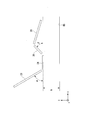
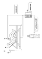
- FIG. 1 is a schematic view showing an outline of the present embodiment.
- a bed system 1 according to the present embodiment includes a bed 10, a hand switch 21, a control box 22, and a terminal device 30.
- the control box 22 is installed in the bed 10 and is connected to the hand switch 21 in a wired or wireless manner.
- the bed 10 is provided with a drive unit.
- the bed 10 can control the height and the elevation of the bottom by the control box 22 operating the drive unit based on the operation instruction input by the user operating the hand switch 21.
- the terminal device 30 is an electronic device provided with a computer system.
- the terminal device 30 is, for example, a device provided with a touch panel such as a smartphone, a tablet terminal device, or a personal computer.
- the touch panel is an electronic component in which a display unit and an input unit are integrally configured.
- the input unit detects the position of the touch (touch) of the finger or the stylus pen on the display unit.
- the touch panel can receive operations such as tap, double tap, long press, flick, pinch in, and pinch out.
- the tap is an operation of touching for a short time.
- the double tap is an operation of performing the tap twice within a predetermined time.
- a long press is an operation of touching for a long time.
- the flick is an operation of moving the position of the touch while touching. The flick may be distinguished by the movement direction of the position of the touch.
- Pinch-in is an operation of bringing the positions of the touch close to each other after touching a plurality of positions.
- the pinch out is an operation of moving the positions of the touch away from each other after touching a plurality of positions.
- the terminal device 30 operates as a remote controller of the bed 10.
- the terminal device 30 displays a control screen for receiving an instruction from the user on the touch panel.
- Operation buttons are arranged on the control screen.
- the operation button is associated with the operation of the bed 10. That is, the operation button is an example of an operating element for operating the bed 10.
- one operation button is associated with a control instruction that raises the height of the bed 10, and another operation button is associated with a control instruction that lowers the foot bottom position.
- the user of the terminal device 30 can cause the bed 10 to perform the operation associated with the operation button by touching the position where the operation button is displayed.
- the user of the terminal device 30 is referred to as a terminal user.
- the user of the bed 10 is called a bed user.
- the case where the terminal user and the bed user are the same will be described.
- the terminal user and the bed user are not particularly distinguished, they are simply referred to as users.
- control screen is displayed based on setting information that can be set for each user, for each bed 10, and the like.
- the setting information corresponds to the display mode of the operation button, the operation button to be displayed, the operation button to be hidden, the operable operation button, the inoperable operation button, the set of control instructions corresponding to the operation button, and the operation button.
- This is information that defines the target value etc. of the control command.
- the display mode includes size, shape, pattern, color, and arrangement.
- the terminal device 30 can display different control screens depending on the user or the bed 10 to be controlled. For example, for a user whose right hand is inconvenient, a control screen on which operation buttons are arranged is displayed on the left side. As a result, the operation button is disposed within the reach of the thumb of the user's left hand, which facilitates operation with the left hand alone.
- the terminal device 30 makes it easy to touch the operation button by displaying the operation button in a large size, for example, for a user who is not good in fine operation. Further, the terminal device 30 does not display or can not operate the operation button for raising and lowering the position of the foot bottom, for example, to the user who is breaking the foot. Thus, the user does not have to be conscious of not performing the operation of moving the foot. As described above, since the terminal device 30 can diversify the display of the operating element, the operability of the bed 10 can be improved.
- the terminal device 30 raises and lowers the position of the foot bottom in a format (also referred to as a first display format) in which the display button for raising and lowering the position of the foot bottom and other operation buttons (back bottom, waist bottom, etc.) are simultaneously displayed.
- a format also referred to as a first display format
- the form also referred to as a second display form
- the terminal device 30 can display the operation button suitable for every user or every bed, and can improve the operativity of the bed 10.
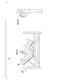
- FIG. 2 is a diagram for explaining the operation of the bed 10.
- a back bottom 23, a hip bottom 24, a knee bottom 26 and a foot bottom 28 are provided in order from the head side to the foot side.
- the waist bottom 24 is fixed to the frame.
- the height of the bed 10 (hereinafter referred to as "bed height") can be controlled by a drive unit.
- the bed height is, for example, a height h from a contact surface (a plane HS shown in FIG. 2) of the bed 10 to a predetermined member of the bed 10 in the vertical direction (Z-axis direction in FIG. 2).
- height h to waist bottom 24 is explained as bed height as an example.
- the back bottom 23 is provided on the frame so as to be rotatable around the waist bottom 24 side.
- the knee bottom 26 is provided on the bed frame so as to be rotatable around the waist bottom 24 side.
- the foot bottom 28 is connected to the knee bottom 26.
- Lifting angle ⁇ from the horizontal state of the back bottom 23 (hereinafter referred to as “first rotation angle ⁇ ”) and lifting angle ⁇ from the horizontal state of the knee bottom 26 (hereinafter, “second rotation angle ⁇ ” )
- first rotation angle ⁇ lifting angle ⁇ from the horizontal state of the knee bottom 26
- the drive unit is described as being capable of controlling the bed height h, the first rotation angle ⁇ , and the second rotation angle ⁇ as an example, but the bed 10 can rotate any member. Alternatively, any member may be made stretchable.
- a mattress MT is usually placed on the back bottom 23, the hip bottom 24, the knee bottom 26 and the foot bottom 28.
- the drive unit is controlled by the control box 22 based on an operation instruction input by the user operating the hand switch
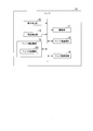
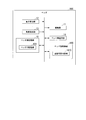
- FIG. 3 is a block diagram showing the configuration of the bed 10.
- the bed 10 includes a height detection unit 12, an angle detection unit 13, a drive unit 11, a bed communication unit 14, a bed storage unit 15, and a bed control unit 16.
- the drive unit 11 includes an electric actuator, and changes the position and angle of each member of the bed 10.
- the height detection unit 12 includes a sensor to detect the bed height h.
- the height detection unit 12 detects, for example, the position of the piston rod of the electric actuator capable of changing the bed height h.
- There is a correlation between the position of the piston rod and the bed height h, and data indicating the correlation is stored in advance in the bed-side storage unit 15. Then, the height detection unit 12 can detect the bed height h based on the position of the piston rod by referring to this data.
- the height detection unit 12 notifies the bed side control unit 16 of the detected bed height h.
- the angle detection unit 13 includes a sensor, and detects a first rotation angle ⁇ and a second rotation angle ⁇ .
- the angle detection unit 13 detects, for example, the position of the piston rod of the electric actuator capable of changing the first rotation angle ⁇ and the second rotation angle ⁇ .
- the angle detection part 13 can detect 1st rotation angle (alpha) and 2nd rotation angle (beta) based on the position of a piston rod by referring this data.
- the angle detection unit 13 notifies the bed-side control unit 16 of the detected first rotation angle ⁇ and the detected second rotation angle ⁇ .
- the bed side communication unit 14 includes, for example, a communication IC (Integrated Circuit), and communicates with other devices such as the terminal device 30.
- the bed communication unit 14 receives a control command from the terminal device 30.
- the bed side communication unit 14 outputs the received control command to the bed side control unit 16.
- the control instruction is an instruction that instructs the operation content of the drive unit 11.
- the control command may include an operation type (e.g., extension, contraction, stop, etc.), an operation amount, an operation speed, and the like.
- the control instruction may directly indicate the operation type (expansion, contraction, stop, etc.), the operation amount, the operation speed, etc., and the code is a code previously associated with these control values, It is also good.
- control instruction may indicate a plurality of operations simultaneously or may indicate a plurality of ordered operations.
- the plurality of operations may be performed by controlling one electric actuator, or may be performed by control in which the plurality of electric actuators are interlocked.
- the bed side communication unit 14 is provided in the hand switch 21 or the control box 22. However, it may be provided in other places.
- the bed-side storage unit 15 includes, for example, an HDD (Hard Disk Drive), an SSD (Solid State Drive), an EEPROM (Electrically Erasable Programmable Read-Only Memory), a ROM (Read-Only Memory), a RAM (Random Access Memory), and the like. , And stores various information, programs, etc. processed by the bed 10.
- the bed-side storage unit 15 is not limited to one built in the bed 10, and may be an external storage device connected by a digital input / output port such as USB (Universal Serial Bus) (registered trademark).
- the bed side storage unit 15 includes a bed ID storage unit 151.
- the bed ID storage unit 151 stores a bed ID (IDentifier).
- the bed ID is identification information assigned to the bed 10.
- the bed ID may be identification information unique to each bed 10 or may be identification information common to the beds 10 of the same type.
- the bed side control unit 16 controls each configuration of the bed 10.
- the bed-side control unit 16 may be realized, for example, by an arithmetic device (for example, a CPU (Central Processing Unit)) included in the bed 10 executing a program stored in the bed ID storage unit 151.
- the bed side control unit 16 may be realized as an integrated circuit such as an application specific integrated circuit (ASIC).
- ASIC application specific integrated circuit
- the bed-side control unit 16 notifies the terminal device 30 of a state indicating the current bed height h, the first rotation angle ⁇ , the second rotation angle ⁇ , and the like via the bed-side communication unit 14.
- the bed-side control unit 16 operates and stops the driving unit 11 in accordance with the control command received from the terminal device 30.
- a communication connection is established between the bed 10 and the terminal device 30.
- Establishing a communication connection is a process of mutually authenticating communication partners, for example, pairing in Bluetooth (registered trademark) communication.
- the bed 10 and the terminal device 30 may establish communication connection by wireless communication such as Wi-Fi (registered trademark), LTE (Long Term Evolution), or the like, or by wired communication via various connection cables.
- the bed side control part 16 makes only the terminal device 30 which established communication connection the control terminal of an own apparatus. That is, the bed-side control unit 16 receives the control command transmitted from the terminal device 30 that has established the communication connection, but does not receive the control command transmitted from the other terminal device 30.
- the terminal device 30 selects a combination of the bed 10 and the terminal device 30 for establishing communication connection.
- the bed-side control unit 16 transmits the bed ID of the own device stored in the bed ID storage unit 151 to the terminal device 30.
- the terminal device 30 transmits the terminal ID to the bed 10 indicated by the bed ID in order to establish a communication connection.
- the terminal ID is information uniquely identifying the terminal device 30.
- the terminal ID may be information identifying a terminal user of the terminal device 30.
- the bed-side control unit 16 authenticates the terminal device 30 indicated by the terminal ID as a communication connection establishment partner. Thereafter, the bed-side control unit 16 receives only the control command from the authenticated terminal device 30. Thereby, since the bed system 1 can operate the bed 10 only by the specific terminal device 30, the safety of the bed 10 can be improved.
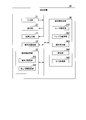
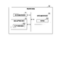
- FIG. 4 is a block diagram showing the configuration of the terminal device 30.
- the terminal device 30 includes an input unit 31, a display unit 32, an audio output unit 33, a terminal communication unit 34, a terminal storage unit 35, and a terminal control unit 36.
- the input unit 31 includes, for example, a touch sensor of a touch panel, and receives an operation input from a user.
- the display unit 32 includes, for example, a liquid crystal display panel of a touch panel, an organic EL (ElectroLuminescence) display panel, or the like, and displays the state of the bed 10 or displays operation buttons for controlling the operation of the bed 10.
- the voice output unit 33 includes, for example, a speaker and outputs a voice for operation guidance and a warning sound.
- the terminal side communication unit 34 includes, for example, a communication IC, and communicates with another device such as the bed 10 or the like.
- the terminal-side storage unit 35 includes, for example, an HDD, an SSD, a ROM, a RAM, and the like, and stores various information, programs, and the like processed by the terminal device 30.
- the terminal-side storage unit 35 is not limited to one built in the terminal device 30, and may be an external storage device.
- the terminal-side storage unit 35 includes a terminal ID storage unit 351 and a setting information storage unit 352.
- the terminal ID storage unit 351 stores a terminal ID.
- the terminal ID may be, for example, a MAC address or an IP address.
- the setting information storage unit 352 stores setting information.
- the operation button setting information may be stored for each terminal ID, each user ID, and each bed ID. That is, the setting information may be information indicating display setting of the operation button for each terminal device 30, for each bed user, for each terminal user, or for each bed 10. Further, a plurality of setting information may be stored for each terminal device 30, for each bed user, for each terminal user, and for each bed 10. In this case, priority may be set to each setting information.
- the setting information may be explicitly or implicitly associated with the terminal ID, the user ID, the bed ID, and the like.
- An explicit association means being linked to each other on data. Implicit association means having a predetermined relationship, such as being managed by the terminal device 30, although not clearly associated with data. Below, the case where setting information is memorize
- the operation setting information is information indicating the correspondence between the operation button and the operation of the bed 10.
- the data configuration of the operation setting information will be described later.
- the terminal device 30 can specify an operation desired by the terminal user and a control command for performing the operation.
- the terminal device 30 can control the enabling and disabling of the operation button.
- the terminal device 30 accepts an operation on the operation button only when the operation corresponding to the operation button is permitted in the operation setting information.
- the terminal device 30 may hide the disabled operation button or may distinguish it from the enabled operation button by decreasing the brightness or the like.
- the first display format is the format for displaying both and the second display for the format in which only the enabled operation button is displayed, without distinguishing between the disabled operation button and the enabled operation button. It is also called a form.
- the first display format and the second format may be switched by the terminal control unit 36.
- the display setting information is information indicating the display mode of the operation button on the control screen.
- the data configuration of the display setting information will be described later.
- the terminal device 30 can make the display mode of the operation button on the control screen different for each terminal user.
- the shape, pattern, color, and arrangement of each operation button may be individually settable by the terminal user.
- a display format in which the operation buttons displayed for each user are different is referred to as a first display format
- a display format in which all the users display the same operation button is also referred to as a first display format.
- the first display format and the second format may be switched by the terminal control unit 36.
- the terminal control unit 36 controls each component of the terminal device 30.
- the terminal-side control unit 36 may be realized, for example, by an arithmetic device (for example, a CPU) included in the terminal device 30 executing a program stored in the terminal-side storage unit 35. Also, the terminal control unit 36 may be realized as an integrated circuit such as an ASIC.
- the terminal side control unit 36 includes a user authentication unit 361, a bed ID acquisition unit 362, an operation reception unit 363, a setting unit 364 and an output processing unit 365.
- the user authentication unit 361 authenticates the user.
- the user authentication unit 361 may authenticate the user based on, for example, a user ID, a password and the like input via the input unit 31. Further, the user authentication unit 361 may perform biometric authentication such as fingerprint authentication or may perform authentication using an IC card unique to the user.
- the user authentication unit 361 notifies the output processing unit 365 of the authentication result.
- the bed ID acquisition unit 362 acquires a bed ID from the bed 10 via the terminal communication unit 34. The bed 10 notifies the output processing unit 365 of the acquired bed ID.
- the operation accepting unit 363 accepts an operation by the terminal user via the input unit 31.
- the operations accepted by the operation accepting unit 363 include, for example, a bed selection operation, a setting operation, and a control operation.
- the bed selection operation is an operation for selecting a bed 10 for establishing communication connection.
- the setting operation is an operation of inputting a setting value described in setting information.
- the control operation is an operation to specify a control command to be transmitted to the bed 10.
- the operation accepting unit 363 notifies the output processing unit 365 of the content of the accepted operation.
- the setting unit 364 edits the setting information.
- editing includes generating information anew, updating the content of the information, and erasing the information.
- the setting unit 364 stores the setting information after editing in the setting information storage unit 352.
- the output processing unit 365 causes the display unit 32 to display various screens.
- the output processing unit 365 causes the display unit 32 to display a bed selection screen, a setting screen, a control screen, and the like.
- the output processing unit 365 refers to the setting information and determines the type of the operation button arranged on the control screen and the display mode of the operation button. Thereby, the type of the operation button to be displayed and the display mode of the operation button are switched for each terminal device 30, each bed user, each terminal user, each bed 10, or each combination thereof.
- the output processing unit 365 performs processing based on the operation content received by the operation receiving unit 363. For example, when the operation is a bed selection operation, the output processing unit 365 transmits the terminal ID to the selected bed 10. For example, when the operation is a setting operation, the output processing unit 365 causes the setting information storage unit 352 to store setting information of the input setting value. The output processing unit 365 transmits the designated control instruction to the bed 10, for example, when the operation is a control operation.
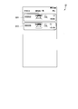
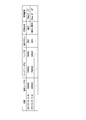
- FIG. 5 is a diagram showing a data configuration of setting information.
- the operation setting information includes the user ID, head speed information, height speed information, interlocking availability information, head operation availability information, foot operation availability information, height operation availability information, and the like.
- the memory availability information, the head memory information, the foot memory information, the height memory information, and the bed leaving notification availability information are mutually associated information.
- the head speed information indicates a pivoting speed for changing the first pivoting angle ⁇ .
- the height speed information indicates the lifting speed to change the bed height h.
- the interlocking availability information indicates the availability of an operation in which a plurality of electric actuators are interlocked.
- the head movement availability information indicates the availability of the rotation operation for changing the first rotation angle ⁇ .
- the foot movement availability information indicates whether or not the rotation movement for changing the second rotation angle ⁇ is possible.
- the height operation availability information indicates the availability of the elevation operation for changing the bed height h.
- the memory availability information changes the state of the bed 10 to target values of a predetermined bed height h, a first rotation angle ⁇ , and a second rotation angle ⁇ (hereinafter referred to as “memory operation”).
- the head memory information indicates a target value of the first rotation angle ⁇ in the memory operation.
- the foot memory information indicates a target value of the second rotation angle ⁇ in the memory operation.
- the height memory information indicates a target value of the bed height h in the memory operation.
- the leaving-behind notification availability information indicates whether to notify that the bed user has left the bed 10 or not.
- FIG. 6 is a diagram showing a data configuration of display setting information.
- the display setting information is information in which the user ID and the display pattern information are associated with each other.
- the display pattern information indicates the display pattern of the control screen.
- a plurality of display patterns are prepared. Then, in each display pattern, the display mode of each operation button is different, or the type of operation button to be displayed is different.
- FIG. 7 is a sequence chart showing the flow of processing by the bed system 1.
- the terminal device 30 performs user authentication. Thereafter, the bed system 1 proceeds with the process to step S100.
- the bed 10 transmits the bed ID to the terminal device 30. Thereafter, the bed system 1 proceeds with the process to step S310.
- Step S310 The terminal device 30 acquires a bed ID from the bed 10 and displays a bed selection screen. A specific example of the bed selection screen will be described later. By acquiring the bed ID, the terminal device 30 can specify the model of the bed 10, the control command that can be received by the bed 10, and the like. Thereafter, the bed system 1 proceeds with the process to step S320.
- Step S320 The terminal device 30 receives a bed selection operation from the terminal user. Thereafter, the bed system 1 proceeds with the process to step S330.
- Step S330 The terminal device 30 requests the bed 10 designated by the bed selection operation to establish communication connection. Thereafter, the bed system 1 advances the process to steps S110 and S340.
- Steps S110 and S340 A communication connection is established between the bed 10 and the terminal device 30. Thereby, the bed 10 can perform an operation according to the control command transmitted from the terminal device 30. In other words, by operating the terminal device 30, the bed 10 can be controlled. Thereafter, the bed system 1 proceeds with the process to step S120.
- Step S120 The bed 10 transmits, to the terminal device 30, state information indicating the state of the bed height h of the own device, the first rotation angle ⁇ , the second rotation angle ⁇ , and the like. Thereafter, the bed system 1 proceeds with the process to step S350.
- Step S350 The terminal device 30 reads setting information from the setting information storage unit 352. Although illustration of processing is omitted here, setting information can be edited by setting operation via a setting screen. A specific example of the setting screen will be described later. Thereafter, the bed system 1 proceeds with the process to step S360.
- Step S360 The terminal device 30 displays a control screen based on the setting information. A specific example of the control screen will be described later. Thereafter, the bed system 1 proceeds with the process to step S370.
- Step S370 The terminal device 30 receives a control operation. Thereafter, the bed system 1 proceeds with the process to step S380.
- Step S380 The terminal device 30 specifies a control command corresponding to the control operation.
- the terminal device 30 transmits control information indicating a control command to the bed 10.
- different control commands may be assigned to the respective models of the bed 10.
- the terminal device 30 stores in advance data indicating the correspondence between the operation and the control command for each model of the bed 10.
- the terminal device 30 specifies a control command corresponding to the control operation by referring to the part of the bed 10 to be controlled among the data. Thereby, the terminal device 30 can control the bed 10 of various types appropriately.
- the bed system 1 proceeds with the process to step S130.
- Step S130 The bed 10 operates the drive unit 11 according to the control command indicated by the control information. Thereafter, the bed system 1 proceeds with the process to step S140.
- Step S140 The bed 10 transmits information indicating the control result of the drive unit 11 to the terminal device 30.
- the control result may include, for example, values of the bed height h, the first rotation angle ⁇ , the second rotation angle ⁇ , and the like.
- the terminal device 30 can accept the next control operation.
- the bed system 1 proceeds the process to step S370, and when the operation of the bed 10 is not necessary, the process illustrated in FIG. 7 ends.
- step S300 may be omitted, or may be performed after the process of steps S110 and S340.
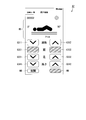
- FIG. 8 is a diagram showing a bed selection screen.
- Selection buttons G11 and G12 are provided on the bed selection screen G1 shown in FIG. 8 as operators for selecting one of the two beds 10 from which the terminal device 30 has acquired the bed ID.
- Each of the selection buttons G11 and G12 may display information such as the bed ID and the communication radio wave intensity with each bed 10.
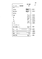
- FIG. 9 is a diagram showing a setting screen.
- setting buttons G211, G212, G221 to G225, G23, G231 to G233, and G24 are provided as operators for specifying setting values of respective items of setting information.
- the setting button G211 is an operator for setting head speed information.
- the setting button G212 is an operation element for setting height speed information.
- the setting button G221 is an operation element for setting interlocking permission information.
- the setting button G222 is an operator for setting head operation availability information.
- the setting button G223 is an operation element for setting the foot operation availability information.
- the setting button G224 is an operator for setting height operation availability information.
- the setting button G225 is an operator for setting memory availability information.
- the setting button G23 is an operator for setting the first rotation angle ⁇ , the second rotation angle ⁇ , and the bed height h of the current bed 10 to head memory information, foot memory information, and height memory information. .
- the setting button G231 is an operator for adjusting the setting value of the head memory information.
- the setting button G232 is an operation element for adjusting the setting value of the foot memory information.
- the setting button G233 is an operation element for adjusting the setting value of height memory information.
- the setting button G24 is an operation element for setting the bed leaving notification availability information. On the setting screen, the display mode of the operating element may be set other than that shown in FIG.
- the control screen G31 shown in FIG. 10 is provided with a bed state display field BS indicating the state of the bed 10 (a first rotation angle ⁇ , a second rotation angle ⁇ , a bed height h, etc.). Further, in the control screen G31, operation buttons G311, G312, G321, G322, G331, G332, G341, G342, FB, and MB are provided as operators for designating a control command.
- the operation buttons G311 and G312 are operators corresponding to the operation of changing both the first rotation angle ⁇ and the second rotation angle ⁇ .
- the operation buttons G321 and G322 are operators corresponding to the operation of changing the first rotation angle ⁇ .
- the operation buttons G331 and G332 are operators corresponding to the operation of changing the second rotation angle ⁇ .
- the operation buttons G341 and G342 are operators corresponding to the operation of changing the bed height h. Further, the operation buttons G311, G321, G331, and G341 reduce both the first rotation angle ⁇ and the second rotation angle ⁇ , the first rotation angle ⁇ , the second rotation angle ⁇ , and the bed height h. Correspond to the operation.
- the operation buttons G312, G322, G332, and G342 increase both the first rotation angle ⁇ and the second rotation angle ⁇ , and increase the first rotation angle ⁇ , the second rotation angle ⁇ , and the bed height h.
- the operation button FB is an operator corresponding to an operation of setting each bottom to a horizontal state by setting both the first rotation angle ⁇ and the second rotation angle ⁇ to zero.
- the operation button MB is an operator corresponding to a memory operation.
- a pattern switching button CB is disposed on the control screen G31.
- the pattern switching button CB is an operator for switching the display pattern of the control screen. That is, the pattern switching button CB is an example of an operator for receiving a display mode change instruction to change the display mode of the operation button.
- the terminal device 30 switches the display to the control screen G32.
- the pattern switching button CB is operated on the control screen G32, the terminal device 30 switches the display to the control screen G31.
- operation buttons similar to the control screen G31 are arranged. However, the arrangement of each operation button is changed so as to invert the left and right. Thereby, for example, even if the terminal user who has one hand is inconvenient, the desired operation button can be moved within the reach of the thumb of the hand with freedom.
- the bed system 1 can improve the operability of the bed 10.
- the display pattern of the control screen is not limited to two, and three or more may be prepared.
- the display patterns may be different in size, shape, pattern, and color.
- the size, shape, pattern, and color of each operation button may be different.
- the size, shape, pattern, color, arrangement, etc. of the operation button may be individually changeable.
- the operation method of each operation button may be different. For example, an operation button for receiving an operation when pressed long and an operation button for receiving an operation when double-tapped may be provided. By receiving only a specific operation method as described above, it is possible to prevent the bed 10 from operating in response to an erroneous operation of the operation button.
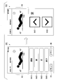
- the control screen G41 shown in FIG. 11 is provided with operation buttons G410, G420, G430, and G440.
- the operation buttons G410, G420, G430, and G440 are operators for selecting an electric actuator to be controlled.
- the operation button G410 is an operation element corresponding to an operation of changing both the first rotation angle ⁇ and the second rotation angle ⁇ .
- the operation button G420 is an operation element corresponding to an operation of changing the first rotation angle ⁇ .
- the operation button G430 is an operator corresponding to an operation of changing the second rotation angle ⁇ .
- the operation button G440 is an operation element corresponding to an operation of changing the bed height h. Each operation may be referred to as a first operation, a second operation, and so on.
- the terminal device 30 transitions the display to a control screen for receiving an input of an operation amount and an operation direction.
- the terminal device 30 displays a control screen G42.
- the control screen G42 is provided with operation buttons G431 and G432.
- the operation button G431 corresponds to an operation of increasing the second rotation angle ⁇ .
- the operation button G432 corresponds to an operation of reducing the second rotation angle ⁇ .
- the terminal device 30 requests to operate the plurality of operation buttons in order to cause the bed 10 to perform one operation. Therefore, even if one operation button is erroneously operated, the bed 10 does not operate immediately. Thus, the bed system 1 can improve the safety of the bed 10.
- the terminal device 30 may request that the plurality of operation buttons be operated simultaneously in order to cause the bed 10 to perform one operation.
- the bed 10 does not operate, for example, when two operation buttons are not touched simultaneously. Therefore, even if one operation button is erroneously operated, the bed 10 does not operate immediately.
- the bed system 1 can improve the safety of the bed 10.
- control screen G41 operation buttons that receive input of the operation amount and the operation direction may be displayed corresponding to the operation buttons G410, G420, G430, and G440. That is, the operation buttons G431 and G432 in the display screen G42 may be displayed in association with the operation buttons G410, G420, G430, and G440.
- the terminal device 30 can receive, from the user, the input of the operation amount and the operation direction of the control target on the control screen G41.
- the display format of the control screen G41 is also referred to as a first display format
- the display format of the control screen G42 is also referred to as a second display format.
- the first display format is a format in which, for example, an operation button G420 for controlling the position of the foot and control buttons (G410, G420, etc.) for controlling other operations are simultaneously displayed.
- the second display format is, for example, a format in which only the operation button G430 for controlling the position of the foot is displayed and the operation buttons (G410, G420, etc.) for controlling other operations are not displayed.
- the first display format and the second format may be switched by the terminal control unit 36.
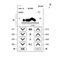
- the control screen G51 shown in FIG. 12 is provided with operation buttons G510, G520, G530, and G540.
- Operation buttons G510, G520, G530, and G540 are operators for selecting an action of the bed user.
- the operation button G510 is an operator for operating the bed 10 so as to be in a state suitable for the bed user to eat.
- the operation button G520 is an operating element for operating the bed 10 so as to be in a state suitable for the bed user to stand up from the bed 10.
- the operation button G530 is an operation element for operating the bed 10 so as to be in a state suitable for the bed user to get up from the bed.
- the operation button G540 is an operation element for operating the bed 10 so as to be in a state suitable for the bed user to go to bed.
- the terminal device 30 displays the bed user's operation procedure and the bed 10's operation procedure for performing the selected action.
- the operation button G520 is operated, the terminal device 30 displays a control screen G53.
- the control screen G53 is provided with operation buttons G521 and G522.
- the operation buttons G ⁇ b> 521 and G ⁇ b> 522 are operators for causing the bed 10 to perform an operation according to each procedure of the action.
- the bed user can operate the bed 10 so as to be in a state suitable for performing each procedure by operating the operation buttons arranged for the description of each procedure. This allows the bed user to easily understand how to move his or her body and how to operate the bed 10 to best perform the desired action. Therefore, the bed user can appropriately use the bed 10 without knowing how to properly use the bed 10.
- the bed system 1 can improve the operability of the bed 10.
- one operation button G521 or operation button G522 is displayed side by side for each operation procedure of the bed user, but one operation button for a plurality of operation procedures. May be displayed in association with each other.
- the control command corresponding to the operation button may be switched sequentially.
- the first operation button functions as the operation button G521
- the second operation button functions as the operation button G522.
- the terminal device 30 may change the control command corresponding to one operation button in accordance with the number of times of operation or the operation timing.
- the terminal device 30 may move the operation button to the vicinity of the corresponding operation procedure as needed, or change the display to make it possible to identify which operation procedure is supported.
- control screen G51 operation buttons that receive input of the operation amount and the operation direction may be displayed corresponding to the operation buttons G510, G520, G530, and G540. That is, the operation buttons G521 and G522 on the display screen G52 may be displayed in association with the operation buttons G510, G520, G530, and G540.
- the terminal device 30 can receive an input of the amount of movement and the movement direction of the control target from the user on the control screen G51.
- the display format of the control screen G51 is also referred to as a first display format
- the display format of the control screen G52 is also referred to as a second display format.
- the first display format is, for example, an operation button G520 for operating the bed 10 so as to be suitable for the bed user to stand up from the bed 10 and a state suitable for other operations.
- the operation buttons (G510, G530, etc.) for operating 10 are simultaneously displayed.
- the second display format is, for example, a format in which only the operation button G520 is displayed and the other operation buttons (G510, G530, etc.) are not displayed.
- the first display format and the second format may be switched by the terminal control unit 36.
- bed system 1 (an example of an information processing system) is provided with bed 10 (an example of a body support device) and terminal unit 30 (an example of a terminal unit).
- the terminal device 30 controls the first operation based on the display unit 32 that displays operation buttons (operation elements) for controlling various operations (first operation and second operation) of the bed 10, and an instruction from the outside.
- a first display form for displaying on the display unit 32 a second control for controlling the first operator and the second operation, and a second for displaying any one of the first and second operators on the display unit 32
- a terminal-side control unit 36 (control unit) that switches between the display format and the display format.
- the bed system 1 can switch the display format according to the user and the bed 10, and can perform display suitable for the user and the bed 10, and can improve the operability of the bed 10.
- the operability of the bed 10 can be improved by hiding the operation button that is not operated for each user, or hiding the operation button of the incompatible operation for each bed 10.
- the terminal device 30 also includes an operation receiving unit 363 (an example of a selection receiving unit) and an output processing unit 365 (an example of a control instruction transmission unit and a display processing unit).
- the operation reception unit 363 receives the selection of the bed 10.
- the output processing unit 365 displays an operation button (an example of an operating element) corresponding to the selected bed 10 on the display unit 32.
- the operation receiving unit 363 receives an input of a control command to the bed 10 based on an operation on the operation button.
- the output processing unit 365 transmits the input control command to the selected bed 10 in accordance with the operation on the operation button.
- the bed system 1 displays the operation button based on the selection of the bed 10 and the setting information according to the bed 10. Therefore, the bed system 1 can customize the display of the operation button for each bed 10 to be controlled. That is, the bed system 1 can customize the display of the operation button for each bed user. Thus, the bed system 1 can improve the operability of the bed 10.
- the terminal device 30 further includes a bed ID acquisition unit 362 (an example of an identification information acquisition unit).
- the bed ID acquisition unit 362 acquires a bed ID (an example of identification information) associated with the bed 10.
- the operation reception unit 363 receives the selection of the bed ID.
- the output processing unit 365 displays the operation button on the display unit 32 based on the bed ID (based on the selection of the bed ID or based on the setting information corresponding to the bed ID).
- the operation receiving unit 363 receives an input of a control command to the bed 10 based on an operation on the operation button.
- the output processing unit 365 transmits the input control command to the bed 10 associated with the selected bed ID in accordance with the operation on the operation button.
- the bed system 1 displays the operation button based on the selection of the bed ID and the setting information corresponding to the bed ID. Therefore, the bed system 1 can customize the display of the operation button for each bed 10 to be controlled. That is, the bed system 1 can customize the display of the operation button for each bed user based on the bed ID. Thus, the bed system 1 can improve the operability of the bed 10.
- the terminal device 30 also includes a setting unit 364 (an example of a setting unit).
- the setting unit 364 generates setting information indicating a display mode of the operation button.
- the output processing unit 365 displays the operation button on the display unit 32 in the display mode indicated by the setting information.
- the bed system 1 displays the operation button in the display mode (size, shape, pattern, color, arrangement) indicated by the setting information. Therefore, the bed system 1 can customize the display mode of the operation button for each bed 10 to be controlled. That is, the bed system 1 can customize the display mode of the operation button for each bed user. Thus, the bed system 1 can improve the operability of the bed 10.
- the setting information is information indicating whether or not the operation button can be displayed
- the output processing unit 365 displays the operation button whose display is permitted in the setting information on the display unit 32.
- the bed system 1 changes the operation button to be displayed according to the bed 10 to be controlled. Therefore, the bed system 1 can appropriately manage, for each bed 10, control instructions that can be received. That is, the bed system 1 can appropriately limit or propose control instructions to be received for each bed user. Thus, the bed system 1 can improve the operability and safety of the bed 10.
- the operation reception unit 363 (an example of a change instruction reception unit) receives an input of a display mode change instruction for changing the display mode of the operation button, and the output processing unit 365 operates the operation button when the display mode change instruction is input. Change the display mode.
- the bed system 1 changes the display mode of the operation button according to the instruction of the user. Therefore, even if the bed system 1 is disposed at a position where it is difficult to operate a desired operation button, for example, in an image, the bed system 1 moves the operation button to a position where it is easy to operate or enlarges the desired operation button Do. Thus, the bed system 1 can improve the operability of the bed 10.
- the operation reception unit 363 receives an input of one control instruction based on an operation on a plurality of operation buttons, and the output processing unit 365 transmits an input one control instruction according to an operation on a plurality of operation buttons. Do.
- the bed system 1 requests operations on a plurality of operation buttons to instruct one operation. In this case, the bed system 1 does not operate the bed 10 even when one operation button is operated. Therefore, for example, even when the terminal user unintentionally operates one operation button, the bed 10 does not operate. Thus, the bed system 1 can improve the safety of the bed 10.
- the output processing unit 365 transmits a plurality of control instructions in a predetermined order to the bed 10 associated with the selected bed ID in response to an operation on one operation button.
- the bed system 1 can cause the bed 10 to perform a complex operation with the operation of one operation button. That is, the terminal user does not have to operate the terminal device 30 multiple times to perform the same operation.
- the bed system 1 can improve the convenience of the bed 10.
- the output processing unit 365 displays the operation button on the display unit 32 based on the setting information corresponding to the user of the own device. Thereby, the bed system 1 displays the operation button based on the setting information for each terminal user. Therefore, the bed system 1 can customize the display of the operation button for each terminal user. Thus, the bed system 1 can improve the operability and safety of the bed 10.
- FIG. 13 is a schematic view showing an outline of the present embodiment.
- the bed system 1A which concerns on this embodiment is equipped with the bed 10 and the terminal device 30 like the bed system 1 which concerns on 1st Embodiment.
- the present embodiment is different in that the bed user and the terminal user are not the same.
- the bed user is a patient and the terminal user is a doctor or a nurse.
- the terminal device 30 displays different control screens according to the position of the terminal user.
- the terminal device 30 manages the setting information in association with the authority information.
- the authority information is information indicating the authority of the terminal user.
- the setting information differs in terms of items according to the authority information. Thereby, the terminal device 30 can control the display and non-display of the operator and the display mode of the operator according to the authority of the terminal user.
- FIG. 14 is a diagram showing a control screen.
- operation buttons similar to the control screen G31 shown in FIG. 10 are arranged.
- an operation button NB is disposed on the control screen G6.
- the operation button NB is an operator for lowering the bed height to the lowest position and setting the first pivot angle ⁇ and the second pivot angle ⁇ to zero so as to level each bottom of the bed 10 for nighttime use. It is.
- the terminal device 30 may add, change, or invalidate a dedicated operation button according to the authority of the terminal user.
- the output processing unit 365 displays the operation button on the display unit 32 based on the setting information corresponding to the authority of the user of the own apparatus.
- the bed system 1A displays the operation button according to the authority of the terminal user. Therefore, the bed system 1A can restrict or permit the use of the operation button according to the authority of the terminal user.
- the bed system 1A can improve not only the operability but also the safety of the bed 10.
- the authority may be determined according to the physical condition of the terminal user as well as the position of the terminal user. For example, the authority may correspond to the required assistance level.
- FIG. 15 is a schematic view showing an outline of the present embodiment.
- the bed system 1B which concerns on this embodiment is equipped with the bed 10 and the terminal device 30 similarly to the bed system 1A which concerns on 2nd Embodiment.
- one bed 10 can be controlled by one terminal device 30, while in the present embodiment, a plurality of beds 10 (bed 10-1, 10-2 differs in that control can be performed.
- a plurality of beds 10 bed 10-1, 10-2 differs in that control can be performed.
- the terminal device 30 receives an operation for an operation permitted in any of the plurality of beds 10 to be controlled.
- the bed system 1B can improve not only the operability of the plurality of beds 10 but also the safety.
- FIG. 16 is a diagram showing a control screen.
- operation buttons similar to the control screen G6 shown in FIG. 14 are arranged.
- operation buttons G321, G322, MB are displayed on the control screen G7. Is disabled. Thereby, the safety of the bed 10 can be improved.
- the terminal device 30 may not transmit the control command to the bed 10 used by the bed user whose operation is prohibited.
- the information on the prohibited operation of each bed 10 or each bed user may be stored in the terminal device 30 or may be stored in the bed 10.
- the display format of the control screen G6 shown in FIG. 14 is also referred to as a first display format
- the display format of the control screen G7 shown in FIG. 16 is also referred to as a second display format.
- the first display format and the second format may be switched by the terminal control unit 36.
- the output processing unit 365 of the terminal device 30 causes the operation buttons displayed on the display unit 32 to be different according to the number of beds 10 that transmit the control command.
- the bed system 1 changes the operation button to be displayed according to the number of beds 10 to be controlled.
- the bed system 1 restricts the operation buttons to be displayed when there are a plurality of beds 10 to be controlled as compared with the case where there is one bed 10 to be controlled. That is, the operation of the bed 10 is restricted. Therefore, even when the physical condition and the like of each bed user are different, the plurality of beds 10 can be operated while maintaining safety.
- the bed system 1 can improve not only the operability of the bed 10 but also the safety.
- FIG. 17 is a schematic view showing an outline of the present embodiment.
- Bed system 1C concerning this embodiment is replaced with bed 10 with which bed system 1, 1A, 1B mentioned above is equipped, and is provided with bed 10C.
- the number of the terminal device 30 controlling the bed 10 is one in each of the embodiments described above, the present embodiment is different in that there are a plurality of terminal devices 30 controlling the bed 10C. Thereby, since the bed 10C can be operated from the plurality of terminal devices 30, operability can be improved.
- a patient who is a bed user and a nurse who is another user each have the terminal device 30.
- the terminal device 30 which a patient has is called the terminal device 30P
- the terminal device 30 which a nurse has is called the terminal device 30N.
- the patient and the nurse have different authorities.
- a case where a nurse has stronger authority than a patient will be described.
- the bed 10C when there are a plurality of terminal devices 30 that control the bed 10C, if the bed 10C equally receives control commands from the plurality of terminal devices 30, there is a possibility that the bed 10C may perform an unintended operation. is there. Therefore, the bed 10C always restricts the party establishing communication connection to one terminal device 30. For example, when there is a connection request from the terminal device 30N, the communication connection is established with the terminal device 30N even when the communication connection with the terminal device 30P is established. That is, the bed 10C gives priority to the communication connection with the terminal user having stronger authority. Thus, not only the operability of the bed 10C can be improved, but also the safety of the bed 10C can be improved.
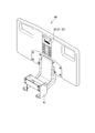
- FIG. 18 is a block diagram showing the configuration of the bed 10C.
- the bed 10 ⁇ / b> C includes a bed-side control unit 16 ⁇ / b> C instead of the bed-side control unit 16 included in the bed 10.
- the bed side control unit 16C includes a connection determination unit 161C.
- the connection determination unit 161C determines whether or not the communication connection with the terminal device 30 may be established.
- the connection determination unit 161C determines that the communication connection with the request source terminal device 30 may be established.
- connection determination unit 161C when the connection determination unit 161C establishes a communication connection with another terminal device 30, the connection permission determination unit 161C selects the terminal device 30 as the request source and the other terminal device 30 currently establishing the communication connection. Between the terminal user's authority is compared. The authority information may be transmitted from the terminal device 30, for example, at the time of request for establishment of communication. The connection determination part 161C establishes or maintains communication connection with the terminal device 30 of the terminal user who has stronger authority. As a result, the connection determination unit 161C can limit the terminal device 30 that receives the control command according to the terminal user's authority and the status of the communication connection.
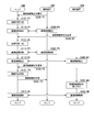
- FIG. 19 is a sequence chart showing the operation of the bed system 1.
- a process related to establishing a communication connection between the bed 10C and the terminal devices 30P and 30N will be extracted and described.
- the terminal device 30P and the terminal device 30N may be appropriately replaced according to the authority of the terminal user.
- the code P1 indicates that the process relates to the first communication connection request from the terminal device 30P.
- the code N1 indicates that the process relates to the first communication connection request from the terminal device 30N
- the code P2 indicates that the process relates to the second communication connection request from the terminal device 30P. Show.
- the partial process shown in FIG. 19 is the same as the process shown in FIG.
- the process of steps S330-P1, S330-N1, and S330-P2 is the same as the process of step S330.
- the processing of steps S110-N1 and S110-P1 is the same as the processing of step S110.
- the processing of steps S380-N1 and S380-P1 is the same as the processing of step S340.
- steps S101-P1, S101-N1, and S101-P2 are all similar processes, some determination results are different.
- Steps S112-P1 and S112-N1 are similar processes.
- S382-P1 and S382-N1 are similar processes.
- Step S330-P1 The terminal device 30P requests the bed 10C to establish communication connection. Thereafter, the bed system 1C proceeds with the process to step S101-P1.
- Step S101-P1 In response to the request from the terminal device 30P, the bed 10C determines whether communication connection can be established. Specifically, the bed 10C determines whether a communication connection with another terminal device 30 has been established. Here, since the communication connection with the other terminal device 30 is not established, the bed 10C determines that the communication connection can be established. Thereafter, the bed system 1C proceeds with the process to steps S110-P1 and S380-P1. (Steps S110-P1, S380-P1) The bed 10C and the terminal device 30P establish communication connection. Thereafter, the bed system 1C proceeds with the process to step S330-N1.
- Step S330-N1 The terminal device 30N requests the bed 10C to establish communication connection. Thereafter, the bed system 1C proceeds with the process to steps S101-N1.
- Step S101-N1 In response to the request from the terminal device 30P, the bed 10C determines whether communication connection can be established. Here, although the bed 10C has already established communication connection with the terminal device 30P, it is determined that the bed 10C establishes communication connection with the terminal device 30N because the terminal device 30N has stronger authority of the terminal user. Do. Thereafter, the bed system 1C proceeds with the process to steps S112-P1 and S382-P1.
- Steps S112-P1, S382-P1 The bed 10C cancels the communication connection with the terminal device 30P. Thereafter, the bed system 1C proceeds with the process to steps S110-N1 and S380-N1. (Steps S110-N1, S380-N1) The bed 10C establishes a communication connection with the terminal device 30P. Thereafter, the bed system 1C proceeds with the process to step S330-P2.
- Step S330-P2 The terminal device 30P requests the bed 10C to establish communication connection. Thereafter, the bed system 1C proceeds with the process to step S101-P2.
- Step S101-P2 In response to the request from the terminal device 30P, the bed 10C determines whether communication connection is possible. Here, since the bed 10C has already established communication connection with the terminal device 30N, and since the terminal device 30N has stronger authority of the terminal user, the bed 10C must establish communication connection with the terminal device 30P. judge. Thereafter, the bed system 1C proceeds with the process to step S102-P2.
- Step S102-P2 The bed 10C notifies the terminal device 30P that the communication connection is to be refused. Thereafter, the bed system 1C proceeds with the process to step S381-N1.
- Step S381-N1 The terminal device 30N receives an operation of releasing the communication connection from the terminal user. In this manner, the disconnection of the communication connection may be performed when explicitly instructed by the terminal user. Thereby, in the bed system 1, since the user of the terminal device 30N can restrict the transfer of the control right of the bed 10C, the safety of the bed 10C can be improved. Thereafter, the bed system 1C proceeds with the process to steps S112-N1 and S382-N1. (Steps S112-N1, S382-N1) The bed 10C and the terminal device 30P release the communication connection. Thereafter, the bed system 1C ends the process shown in FIG.
- the bed 10C includes the connection possibility determination unit 161C (an example of a determination unit) that determines whether or not to receive a control command of the terminal device 30.
- bed system 1C limits terminal unit 30 in which bed 10 receives a control command. That is, the number of terminal devices 30 that can control the bed 10 is limited to one. Therefore, even when there are a plurality of terminal devices 30, the bed 10 does not perform an unintended operation by a control command from the plurality of terminal devices 30. Therefore, the bed system 1 can improve not only the operability but also the safety of the bed 10.
- FIG. 20 is a schematic view showing an outline of the present embodiment.
- the bed system 1D according to the present embodiment is a system including the beds 10 and 10C and the terminal device 30, as in the bed systems 1 and 1A to 1C according to the above-described embodiments.
- bed system 1D differs in a point further provided with history analysis device 50 which accumulates and analyzes control history of bed 10 (or bed 10C) by terminal unit 30.
- history analysis device 50 which accumulates and analyzes control history of bed 10 (or bed 10C) by terminal unit 30.
- the history analysis device 50 is an electronic device provided with a computer system, for example, a server device.
- the history analysis device 50 may collect control history from a plurality of beds 10 and terminal devices 30.
- the history analysis device 50 analyzes the usage status of each bed 10, the preference of the terminal user, the preference of the bed user, and the like based on the collected control history.
- the history analysis device 50 can analyze which electric actuator of the bed 10 is used to what extent.
- the history analysis apparatus 50 can estimate what bed 10 each bed user prefers.
- the history analysis apparatus 50 can analyze which operation each terminal user prefers.
- the bed system 1D can facilitate maintenance of the bed 10, recommend the beds 10 and 10C, and improve control settings of operation.
- FIG. 21 is a block diagram showing the configuration of the history analysis apparatus 50.
- the history analysis device 50 includes an analysis device communication unit 51, an analysis device storage unit 52, and an analysis device control unit 53.
- the analysis device communication unit 51 includes, for example, a communication IC, and communicates with other devices such as the terminal device 30 and the bed 10.
- the analysis device side communication unit 51 receives communication history information from the terminal device 30 or the bed 10.
- the analysis device side storage unit 52 includes, for example, an HDD, an SSD, a ROM, a RAM, and the like, and stores various information, programs, and the like processed by the history analysis device 50.
- the history information storage unit 521 is not limited to one built in the history analysis device 50, and may include an external storage device.
- the analysis device side storage unit 52 includes a history information storage unit 521.
- the history information storage unit 521 stores the history information received by the analysis device communication unit 51.
- the history information is information indicating the control history of the bed 10. The data configuration of the history information will be described later.
- the history analysis apparatus 50 receives the operation when and by whom the user is using the bed 10 and as a result of the control being performed by the person 10. Can identify what kind of state it was.
- the analysis device side control unit 53 controls each component of the history analysis device 50.
- the analysis device side control unit 53 may be realized, for example, by an arithmetic device (for example, a CPU) included in the history analysis device 50 executing a program stored in the analysis device side storage unit 52. Also, the analysis device side control unit 53 may be realized as an integrated circuit such as an ASIC.
- the analysis device side control unit 53 includes an analysis unit 531.
- the analysis unit 531 analyzes history information.
- the analysis unit 531 analyzes history information for each bed ID, each terminal user ID, and each bed user ID, for example. For example, the analysis unit 531 extracts history information based on the bed ID.
- the analysis unit 531 refers to the control command information of the extracted history information, and calculates, for example, the drive performance of the electric actuator up to now, such as the drive amount and the number of times of drive. Thereby, the analysis unit 531 can analyze the possibility of the failure of the bed 10. Based on the analysis result, for example, when the drive record exceeds a predetermined threshold, the analysis unit 531 may notify the terminal device 30 that maintenance inspection is necessary.
- the analysis unit 531 extracts history information based on the terminal user ID.
- the analysis unit 531 refers to the operation button information of the extracted history information, and calculates the number of times of use of each operation button. Thereby, the analysis unit 531 can specify the preference of the operation button for each terminal user.
- the analysis unit 531 may propose, to the terminal user, a control screen easy to use for the operation button frequently used.
- the analysis unit 531 extracts history information based on the bed user ID.
- the analysis unit 531 refers to the control result information of the extracted history information, and calculates, for each state of the bed 10, the length of time taken for the state.
- the analysis unit 531 can specify the preference of the bed 10 for each bed user. Based on the analysis result, for example, the analysis unit 531 may suggest the use of another bed 10 to the bed user. For example, for bed users who prefer low bed height h, the use of a low bed 10 may be suggested.
- FIG. 22 shows the data structure of history information.
- the history information is information in which date and time information, terminal user ID, bed user ID, bed ID, operation button information, control command information, and control result information are mutually associated. It is.
- the date and time information is information indicating the date and time when the terminal device 30 received an operation or the date and time when the control command was transmitted to the bed 10.
- the terminal user ID is a user ID indicating a terminal user of the terminal device 30.
- the bed user ID is a user ID indicating a bed user of the bed 10.
- the operation button information is information indicating an operation button operated by the terminal user.
- the control command information is information indicating a control command accepted by the bed 10.
- the control result information is information indicating the state of the bed 10 as a control result by the terminal device 30.
- the bed system 1D includes the history analysis device 50.
- the history analysis device 50 includes an analysis device side storage unit 52 that stores the history of the input control command.
- bed system 1D enables tracking of control contents to bed 10. Therefore, it becomes possible to analyze, for example, the load applied to the driving unit 11 of the bed 10, the usage tendency of the bed 10 for each bed user, and the like. And these analysis results can be utilized for maintenance of bed 10, and a proposal to a bed user.
- the states of the beds 10 and 10C and the contents of the control command may be notified by voice.
- a warning sound of an emergency stop may be output from the bed 10 or 10C or the terminal device 30.
- a body support device provided with an electric actuator such as a wheelchair or an incubator may be controlled.
- an input device such as a mouse or a keyboard may be used for operation input.
- the terminal device 30 may acquire the attribute information of bed 10, 10C.
- the attribute information of the beds 10 and 10C may include a model, an installation place, and the like.
- the terminal device 30 may change the setting information to be referred to at the time of generation of the control screen according to the attribute information. For example, by changing the setting information according to the installation place of the beds 10 and 10C, for example, different control screens can be displayed for each hospital room.
- bed 10, 10C may be equipped with the sensor which acquires a bed user's biometric information.
- biological information for example, body movement, pulse, blood pressure or the like may be acquired.
- the beds 10 and 10C may notify the terminal device 30 of the acquired biological information. Then, the terminal device 30 may limit the control command to be transmitted to the beds 10 and 10C based on the biological information.
- setting information stored in the terminal device 30 was demonstrated in each embodiment mentioned above, it is not restricted to this.
- the setting information may be stored in, for example, a server device on the network and may be referable from any device. As a result, setting information corresponding to one user ID can be used in any terminal device 30.
- FIG. 23 is a view showing an example in which the present invention is applied to a side rail.
- the side rail 60 has a coupling portion 61, and the coupling portion 61 is used by being coupled (mounted) to the side surface of the bed 10 or 10C.
- the side rail 60 incorporates other functions of the terminal device 30 and receives an operation from the user.
- the user can operate the beds 10 and 10C on the bed without holding the independent terminal device 30 such as a smartphone.
- a program for realizing the functions of the bed 10, 10C, the terminal device 30, and the history analysis device 50 described above is recorded in a computer readable recording medium, and the program recorded in the recording medium is read into the computer system
- the processes as the beds 10 and 10C, the terminal device 30, and the history analysis apparatus 50 may be performed by executing the process.
- "to read and execute the program recorded on the recording medium into the computer system” includes installing the program on the computer system.
- the “computer system” mentioned here includes an OS and hardware such as peripheral devices.
- the “computer system” may include a plurality of computer devices connected via a network including communication lines such as the Internet, WAN, LAN, and dedicated lines.
- the “computer-readable recording medium” means a portable medium such as a flexible disk, a magneto-optical disk, a ROM, a CD-ROM, or a storage device such as a hard disk built in a computer system.
- the recording medium storing the program may be a non-transitory recording medium such as a CD-ROM.
- the recording medium also includes a recording medium provided internally or externally accessible from the distribution server for distributing the program.
- the code of the program stored in the recording medium of the distribution server may be different from the code of the program executable in the terminal device. That is, the format stored in the distribution server does not matter as long as it can be downloaded from the distribution server and installed in a form that can be executed by the terminal device.
- the program may be divided into a plurality of parts, and the configuration may be such that the terminal device integrates after being downloaded at different timings, or the distribution server that distributes each of the divided programs may be different.
- “computer-readable recording medium” holds a program for a certain period of time, such as a volatile memory (RAM) in a computer system serving as a server or a client when the program is transmitted via a network.
- the program may be for realizing a part of the functions described above.
- it may be a so-called difference file (difference program) that can realize the above-described functions in combination with a program already recorded in the computer system.
- some or all of the functions of the beds 10 and 10A, the terminal device 30, and the history analysis apparatus 50 described above may be realized as an integrated circuit such as a large scale integration (LSI).
- LSI large scale integration
- Each function mentioned above may be processor-ized separately, and part or all may be integrated and processor-ized.
- the method of circuit integration is not limited to LSI's, and implementation using dedicated circuitry or general purpose processors is also possible. In the case where an integrated circuit technology comes out to replace LSI's as a result of the advancement of semiconductor technology, integrated circuits based on such technology may also be used.
- the operability of the body support device can be improved.
Landscapes
- Engineering & Computer Science (AREA)
- Health & Medical Sciences (AREA)
- Public Health (AREA)
- General Health & Medical Sciences (AREA)
- Theoretical Computer Science (AREA)
- Veterinary Medicine (AREA)
- Life Sciences & Earth Sciences (AREA)
- Animal Behavior & Ethology (AREA)
- General Engineering & Computer Science (AREA)
- Biomedical Technology (AREA)
- Physics & Mathematics (AREA)
- Human Computer Interaction (AREA)
- General Physics & Mathematics (AREA)
- Nursing (AREA)
- Epidemiology (AREA)
- Business, Economics & Management (AREA)
- General Business, Economics & Management (AREA)
- Medical Informatics (AREA)
- Primary Health Care (AREA)
- Signal Processing (AREA)
- Computer Networks & Wireless Communication (AREA)
- Invalid Beds And Related Equipment (AREA)
- Selective Calling Equipment (AREA)
- Telephone Function (AREA)
Priority Applications (4)
| Application Number | Priority Date | Filing Date | Title |
|---|---|---|---|
| CN202310052514.0A CN116019647B (zh) | 2017-08-30 | 2018-04-06 | 终端装置 |
| US16/485,269 US11289191B2 (en) | 2017-08-30 | 2018-04-06 | Terminal device and program |
| CN201880014408.0A CN110958868B (zh) | 2017-08-30 | 2018-04-06 | 身体支承系统 |
| US17/674,179 US11776685B2 (en) | 2017-08-30 | 2022-02-17 | Terminal device and program |
Applications Claiming Priority (2)
| Application Number | Priority Date | Filing Date | Title |
|---|---|---|---|
| JP2017165536A JP7049786B2 (ja) | 2017-08-30 | 2017-08-30 | ベッドシステム |
| JP2017-165536 | 2017-08-30 |
Related Child Applications (2)
| Application Number | Title | Priority Date | Filing Date |
|---|---|---|---|
| US16/485,269 A-371-Of-International US11289191B2 (en) | 2017-08-30 | 2018-04-06 | Terminal device and program |
| US17/674,179 Division US11776685B2 (en) | 2017-08-30 | 2022-02-17 | Terminal device and program |
Publications (1)
| Publication Number | Publication Date |
|---|---|
| WO2019044022A1 true WO2019044022A1 (ja) | 2019-03-07 |
Family
ID=65525300
Family Applications (1)
| Application Number | Title | Priority Date | Filing Date |
|---|---|---|---|
| PCT/JP2018/014709 Ceased WO2019044022A1 (ja) | 2017-08-30 | 2018-04-06 | 端末装置及びプログラム |
Country Status (4)
| Country | Link |
|---|---|
| US (2) | US11289191B2 (enExample) |
| JP (1) | JP7049786B2 (enExample) |
| CN (2) | CN110958868B (enExample) |
| WO (1) | WO2019044022A1 (enExample) |
Families Citing this family (5)
| Publication number | Priority date | Publication date | Assignee | Title |
|---|---|---|---|---|
| JP7049786B2 (ja) | 2017-08-30 | 2022-04-07 | パラマウントベッド株式会社 | ベッドシステム |
| JP7323661B2 (ja) * | 2017-08-30 | 2023-08-08 | パラマウントベッド株式会社 | 端末装置 |
| JP7284638B2 (ja) * | 2019-06-05 | 2023-05-31 | パラマウントベッド株式会社 | 制御装置及び電動家具 |
| JP7645161B2 (ja) * | 2021-09-30 | 2025-03-13 | パラマウントベッド株式会社 | 医療用ベッド |
| TWI803397B (zh) * | 2022-07-21 | 2023-05-21 | 施權航 | 電動床 |
Citations (10)
| Publication number | Priority date | Publication date | Assignee | Title |
|---|---|---|---|---|
| JP2010191722A (ja) * | 2009-02-18 | 2010-09-02 | Kyocera Mita Corp | コンピュータプログラム |
| JP2011050446A (ja) * | 2009-08-31 | 2011-03-17 | Carecom Co Ltd | 電動ベッド制御システム |
| JP2011162007A (ja) * | 2010-02-08 | 2011-08-25 | Tokai Rika Co Ltd | 車両用シート調整装置 |
| JP2013062694A (ja) * | 2011-09-14 | 2013-04-04 | Aisin Seiki Co Ltd | シートレイアウト制御装置及び携帯情報端末用コンピュータプログラム |
| JP2013144045A (ja) * | 2012-01-16 | 2013-07-25 | France Bed Co Ltd | ベッド装置の手元操作装置 |
| WO2014185164A1 (ja) * | 2013-05-15 | 2014-11-20 | パラマウントベッド株式会社 | ベッド装置 |
| JP2016076038A (ja) * | 2014-10-03 | 2016-05-12 | 株式会社サルカン | 表示処理装置、表示処理プログラム、表示処理方法 |
| JP2016167385A (ja) * | 2015-03-09 | 2016-09-15 | パナソニックIpマネジメント株式会社 | 携帯端末及び機器制御システム |
| JP2016193371A (ja) * | 2016-08-25 | 2016-11-17 | パナソニックIpマネジメント株式会社 | 電動ベッド |
| US20170172827A1 (en) * | 2015-12-22 | 2017-06-22 | Stryker Corporation | Patient Support Systems And Methods For Assisting Caregivers With Patient Care |
Family Cites Families (17)
| Publication number | Priority date | Publication date | Assignee | Title |
|---|---|---|---|---|
| US8065024B2 (en) * | 2002-03-18 | 2011-11-22 | Paramount Bed Co., Ltd. | Coordinative control system for adjusting the back and knee bottom sections of an adjustable bed |
| JP3818502B2 (ja) * | 2002-03-18 | 2006-09-06 | パラマウントベッド株式会社 | ベッド等における背膝ボトム連動制御方法 |
| JP2004141484A (ja) | 2002-10-25 | 2004-05-20 | Gac Corp | 遠隔操作システムおよびその制御方法 |
| US7690059B2 (en) * | 2005-12-19 | 2010-04-06 | Stryker Corporation | Hospital bed |
| US7472439B2 (en) * | 2005-02-23 | 2009-01-06 | Stryker Canadian Management, Inc. | Hospital patient support |
| US8926535B2 (en) * | 2006-09-14 | 2015-01-06 | Martin B. Rawls-Meehan | Adjustable bed position control |
| US10864137B2 (en) * | 2006-09-14 | 2020-12-15 | Ascion, Llc | System and method of an adjustable bed with a vibration motor |
| US8572778B2 (en) * | 2007-03-30 | 2013-11-05 | Hill-Rom Services, Inc. | User interface for hospital bed |
| JP2014204846A (ja) * | 2013-04-12 | 2014-10-30 | パラマウントベッド株式会社 | ベッド操作装置及びプログラム |
| CN105142464B (zh) * | 2013-04-25 | 2016-10-19 | 八乐梦床业有限公司 | 床装置以及床装置的控制方法 |
| US9463126B2 (en) * | 2014-03-11 | 2016-10-11 | Hill-Rom Services, Inc. | Caregiver universal remote cart for patient bed control |
| US10420687B2 (en) * | 2015-05-12 | 2019-09-24 | Stryker Corporation | Battery management for patient support apparatuses |
| US11224294B2 (en) * | 2015-06-19 | 2022-01-18 | Tempur World, Llc | Adjustable base assemblies, systems and related methods |
| JP2017070352A (ja) | 2015-10-05 | 2017-04-13 | 株式会社ミツバ | 移動支援装置 |
| US10905609B2 (en) * | 2015-11-20 | 2021-02-02 | Stryker Corporation | Patient support systems and methods for assisting caregivers with patient care |
| JP6262194B2 (ja) | 2015-12-25 | 2018-01-17 | パラマウントベッド株式会社 | 電動ベッド |
| JP7049786B2 (ja) | 2017-08-30 | 2022-04-07 | パラマウントベッド株式会社 | ベッドシステム |
-
2017
- 2017-08-30 JP JP2017165536A patent/JP7049786B2/ja active Active
-
2018
- 2018-04-06 US US16/485,269 patent/US11289191B2/en active Active
- 2018-04-06 CN CN201880014408.0A patent/CN110958868B/zh active Active
- 2018-04-06 WO PCT/JP2018/014709 patent/WO2019044022A1/ja not_active Ceased
- 2018-04-06 CN CN202310052514.0A patent/CN116019647B/zh active Active
-
2022
- 2022-02-17 US US17/674,179 patent/US11776685B2/en active Active
Patent Citations (10)
| Publication number | Priority date | Publication date | Assignee | Title |
|---|---|---|---|---|
| JP2010191722A (ja) * | 2009-02-18 | 2010-09-02 | Kyocera Mita Corp | コンピュータプログラム |
| JP2011050446A (ja) * | 2009-08-31 | 2011-03-17 | Carecom Co Ltd | 電動ベッド制御システム |
| JP2011162007A (ja) * | 2010-02-08 | 2011-08-25 | Tokai Rika Co Ltd | 車両用シート調整装置 |
| JP2013062694A (ja) * | 2011-09-14 | 2013-04-04 | Aisin Seiki Co Ltd | シートレイアウト制御装置及び携帯情報端末用コンピュータプログラム |
| JP2013144045A (ja) * | 2012-01-16 | 2013-07-25 | France Bed Co Ltd | ベッド装置の手元操作装置 |
| WO2014185164A1 (ja) * | 2013-05-15 | 2014-11-20 | パラマウントベッド株式会社 | ベッド装置 |
| JP2016076038A (ja) * | 2014-10-03 | 2016-05-12 | 株式会社サルカン | 表示処理装置、表示処理プログラム、表示処理方法 |
| JP2016167385A (ja) * | 2015-03-09 | 2016-09-15 | パナソニックIpマネジメント株式会社 | 携帯端末及び機器制御システム |
| US20170172827A1 (en) * | 2015-12-22 | 2017-06-22 | Stryker Corporation | Patient Support Systems And Methods For Assisting Caregivers With Patient Care |
| JP2016193371A (ja) * | 2016-08-25 | 2016-11-17 | パナソニックIpマネジメント株式会社 | 電動ベッド |
Also Published As
| Publication number | Publication date |
|---|---|
| JP2019041842A (ja) | 2019-03-22 |
| CN116019647B (zh) | 2025-09-05 |
| CN116019647A (zh) | 2023-04-28 |
| CN110958868A (zh) | 2020-04-03 |
| US11289191B2 (en) | 2022-03-29 |
| US20190378612A1 (en) | 2019-12-12 |
| CN110958868B (zh) | 2023-02-28 |
| US11776685B2 (en) | 2023-10-03 |
| US20220172834A1 (en) | 2022-06-02 |
| JP7049786B2 (ja) | 2022-04-07 |
Similar Documents
| Publication | Publication Date | Title |
|---|---|---|
| WO2019044022A1 (ja) | 端末装置及びプログラム | |
| US20130088452A1 (en) | Device controller with connectable touch user interface | |
| JP2008200173A (ja) | 電子内視鏡用プロセッサ | |
| JP2007130476A (ja) | 手術台のベッドの調節用装置 | |
| AU2017280957A1 (en) | Application icon customization | |
| WO2013099580A1 (ja) | 医療用内視鏡システム | |
| JP6897824B1 (ja) | 情報処理装置、情報処理システム、情報提供方法、及びプログラム | |
| KR20170107987A (ko) | 정보 처리 장치, 정보 처리 방법, 프로그램 및 시스템 | |
| CN107113478B (zh) | 控制装置、存储介质、控制方法以及控制系统 | |
| JP2015186206A (ja) | 制御システム、端末装置、および制御方法 | |
| JP2009032126A (ja) | Kvmスイッチ及びそのドライバプログラム、並びに情報処理装置及び制御プログラム | |
| JP2014109723A (ja) | 画像処理装置、電子機器、画像処理装置の制御方法、電子機器の制御方法、及びプログラム | |
| JP7323661B2 (ja) | 端末装置 | |
| US20160188188A1 (en) | Patient user interface for controlling a patient display | |
| US11992942B2 (en) | Control apparatus, control method, and master-slave system | |
| JPWO2017064996A1 (ja) | 内視鏡プロセッサ | |
| JP5201951B2 (ja) | Kvmスイッチ、情報処理装置及びプログラム | |
| JP2015141487A (ja) | 操作支援プログラムおよび端末装置 | |
| EP3744281B1 (en) | Microscope system and method for operating a surgical microscope | |
| JP2025171611A (ja) | 情報処理装置 | |
| JP6246523B2 (ja) | Kvmスイッチ及びkvmシステム | |
| Mettouris et al. | An adaptive integrated environment for assisted living | |
| JP2023049060A (ja) | 書画カメラ | |
| JP5511023B2 (ja) | 映像表示システム及び方法 | |
| JP2008023126A (ja) | 手術制御システム |
Legal Events
| Date | Code | Title | Description |
|---|---|---|---|
| 121 | Ep: the epo has been informed by wipo that ep was designated in this application |
Ref document number: 18850521 Country of ref document: EP Kind code of ref document: A1 |
|
| NENP | Non-entry into the national phase |
Ref country code: DE |
|
| 122 | Ep: pct application non-entry in european phase |
Ref document number: 18850521 Country of ref document: EP Kind code of ref document: A1 |