WO2019043838A1 - 通信装置、通信方法、及び通信処理プログラム - Google Patents
通信装置、通信方法、及び通信処理プログラム Download PDFInfo
- Publication number
- WO2019043838A1 WO2019043838A1 PCT/JP2017/031197 JP2017031197W WO2019043838A1 WO 2019043838 A1 WO2019043838 A1 WO 2019043838A1 JP 2017031197 W JP2017031197 W JP 2017031197W WO 2019043838 A1 WO2019043838 A1 WO 2019043838A1
- Authority
- WO
- WIPO (PCT)
- Prior art keywords
- communication
- link
- wireless communication
- data
- distance wireless
- Prior art date
Links
Images


Classifications
-
- H—ELECTRICITY
- H04—ELECTRIC COMMUNICATION TECHNIQUE
- H04W—WIRELESS COMMUNICATION NETWORKS
- H04W4/00—Services specially adapted for wireless communication networks; Facilities therefor
- H04W4/80—Services using short range communication, e.g. near-field communication [NFC], radio-frequency identification [RFID] or low energy communication
-
- H—ELECTRICITY
- H04—ELECTRIC COMMUNICATION TECHNIQUE
- H04W—WIRELESS COMMUNICATION NETWORKS
- H04W8/00—Network data management
- H04W8/005—Discovery of network devices, e.g. terminals
-
- H—ELECTRICITY
- H04—ELECTRIC COMMUNICATION TECHNIQUE
- H04W—WIRELESS COMMUNICATION NETWORKS
- H04W28/00—Network traffic management; Network resource management
- H04W28/02—Traffic management, e.g. flow control or congestion control
- H04W28/0215—Traffic management, e.g. flow control or congestion control based on user or device properties, e.g. MTC-capable devices
- H04W28/0221—Traffic management, e.g. flow control or congestion control based on user or device properties, e.g. MTC-capable devices power availability or consumption
-
- H—ELECTRICITY
- H04—ELECTRIC COMMUNICATION TECHNIQUE
- H04W—WIRELESS COMMUNICATION NETWORKS
- H04W84/00—Network topologies
- H04W84/18—Self-organising networks, e.g. ad-hoc networks or sensor networks
- H04W84/20—Master-slave selection or change arrangements
-
- H—ELECTRICITY
- H04—ELECTRIC COMMUNICATION TECHNIQUE
- H04W—WIRELESS COMMUNICATION NETWORKS
- H04W88/00—Devices specially adapted for wireless communication networks, e.g. terminals, base stations or access point devices
- H04W88/02—Terminal devices
- H04W88/06—Terminal devices adapted for operation in multiple networks or having at least two operational modes, e.g. multi-mode terminals
-
- Y—GENERAL TAGGING OF NEW TECHNOLOGICAL DEVELOPMENTS; GENERAL TAGGING OF CROSS-SECTIONAL TECHNOLOGIES SPANNING OVER SEVERAL SECTIONS OF THE IPC; TECHNICAL SUBJECTS COVERED BY FORMER USPC CROSS-REFERENCE ART COLLECTIONS [XRACs] AND DIGESTS
- Y02—TECHNOLOGIES OR APPLICATIONS FOR MITIGATION OR ADAPTATION AGAINST CLIMATE CHANGE
- Y02D—CLIMATE CHANGE MITIGATION TECHNOLOGIES IN INFORMATION AND COMMUNICATION TECHNOLOGIES [ICT], I.E. INFORMATION AND COMMUNICATION TECHNOLOGIES AIMING AT THE REDUCTION OF THEIR OWN ENERGY USE
- Y02D30/00—Reducing energy consumption in communication networks
- Y02D30/70—Reducing energy consumption in communication networks in wireless communication networks
Definitions
- the present invention relates to the technical field of a communication system in which one communication device can perform near field communication with each of a plurality of communication devices.
- wireless LAN standards such as Bluetooth (registered trademark) (hereinafter referred to as "BT") and Wi-Fi (registered trademark) are known as short-distance wireless communication standards.
- BT Bluetooth
- Wi-Fi registered trademark
- short-distance wireless communication standards For example, in the short distance wireless communication method based on BT, the communication device is divided into a master device and a slave device. Then, in the short-distance wireless communication method based on BT, after a link is established (multipoint connection) by pairing between one master device and each of a plurality of slave devices, the master device is established a link It is possible to perform near field communication simultaneously with a plurality of slave devices.
- pairing means a procedure for establishing a link between the master device and the slave device (in other words, a procedure for associating the master device and the slave device).
- the establishment of the link is maintained even if the power of the master device or the slave device is turned off unless the pairing is released, for example, and the communication range between the master device and the slave device ( If within the communicable zone), near field communication can be performed immediately.
- authentication information of a wireless LAN or BT is transmitted using an infrared communication method or a non-contact proximity communication method based on NFC (Near field radio communication), and wireless information is transmitted using the authentication information.
- a technology (handover technology) is disclosed that enables the user to automatically use the communication function related to the wireless LAN or BT without performing authentication processing or setting processing by performing authentication setting on the LAN or BT. .
- the near-field wireless communication function of another communication device not performing near-field wireless communication with the two communication devices in the arbitrary time zone may be turned off by the user's operation. It is possible. However, such an operation is not efficient, and this becomes more remarkable as the number of other communication devices with which a link is established with a specific communication device increases.
- the present invention has been made in view of the above points and the like, and maintains the establishment of a link between a specific communication device and each of a plurality of communication devices (communication counterparts) while maintaining an arbitrary time zone. It is an object of the present invention to provide a communication device, a communication method, and a communication processing program capable of efficiently restricting transmission and reception of data by the short distance wireless communication with another communication device not performing the short distance wireless communication. Do.
- the link required for the first near-field wireless communication is established with the communication partner existing within the first communicable range
- the link The first communication unit performing the first short distance wireless communication with the established communication counterpart, and the second communication counterpart existing within a second communication coverage narrower than the first communication coverage.
- a second communication unit for performing near field communication, and a detection unit for detecting that any one of the plurality of communication partners for which the link is established has entered the second communicable range;
- the detection unit detects that the communication partner has entered the second communicable range the establishment of the link with each of the plurality of communication partners for which the link is established is maintained.
- the vehicle has entered the second communicable range Characterized in that it comprises a communication control unit for limiting the transmission and reception of data by the first short-range wireless communication between the communication partner other than the communication partner.
- the present invention while maintaining the establishment of a link between a specific communication device and each of a plurality of communication partners, between the other communication partners not performing the first short distance wireless communication in an arbitrary time zone. Transmission and reception of data by the first short distance wireless communication can be efficiently limited.
- the invention according to claim 2 is the communication apparatus according to claim 1, wherein the communication partner whose transmission and reception of data by the first short distance wireless communication is restricted by the detection unit is within the second communicable range.
- the communication control unit maintains the establishment of the link between each of the plurality of communication partners with which the link has been established, and within the second communicable range.
- the restriction on the transmission and reception of the data with the communication party whose entry has been further detected is released, and the first nearness to the communication party other than the communication party whose restriction on the transmission and reception of the data is released It is characterized in that transmission and reception of data by distance wireless communication is limited.
- the present invention in a specific communication device, it is possible to switch quickly and efficiently a communication partner that does not restrict transmission and reception of data by the first short distance wireless communication.
- the invention according to claim 3 is the communication apparatus according to claim 1 or 2, wherein the communication control unit is configured to receive the first near-field from a communication partner in which transmission and reception of data by the first near-field wireless communication is limited. It is characterized in that it does not respond to a predetermined command by distance wireless communication.
- data indicating a predetermined command is received by the first near-field wireless communication from a communication partner whose transmission and reception of data by the first near-field wireless communication is limited. Also, by not responding to the command, transmission and reception of data by the first short distance wireless communication with the communication partner can be efficiently restricted.
- the invention according to claim 4 is the communication apparatus according to any one of claims 1 to 3, wherein the communication apparatus comprises a battery for supplying electric power to each part of the communication apparatus, and the link is established.
- the communication control unit determines that the link is established with each of the plurality of communication partners.
- the power consumption mode of the battery is switched from the normal mode to the power saving mode while maintaining the establishment of the link, and then, the detection unit performs communication of any one of the plurality of communication partners for which the link is established.
- the communication control unit switches the power consumption mode of the battery from the power saving mode to the normal mode, It entered the serial second within the communicable range, characterized in that characterized in that to limit the transmission and reception of data by the first short-range wireless communication between the communication partner other than the detected communication partner.
- data by the first short distance wireless communication with another communication partner not performing the first short distance wireless communication in an arbitrary time zone while suppressing the power consumption of the battery Transmission and reception can be efficiently limited.
- the invention according to claim 5 is that, in the communication apparatus according to claim 4, the state in which the first short distance wireless communication is not performed with any of the plurality of communication partners for which the link is established continues for a predetermined time.
- the communication control unit switches the power consumption mode of the battery from the normal mode to the power saving mode while maintaining the establishment of the link with each of the plurality of communication partners for which the link is established.
- the present invention is characterized in that the restriction with respect to all the communication partners whose transmission and reception of data by the first short distance wireless communication is restricted is canceled.
- the invention according to claim 6 is the communication apparatus according to any one of claims 1 to 5, wherein the detection unit detects that the communication partner has entered the second communicable range.
- the communication control unit acquires the remaining amount of power of the battery of the other party of communication whose inside of the second communicable range is detected, and the obtained remaining amount of power is less than the threshold, the communication It is characterized by notifying that the remaining electric energy of the other party's battery is small.
- a communication partner whose remaining power of the battery is less than a threshold as a communication partner whose transmission and reception of data by the first short distance wireless communication is not restricted.
- the invention according to claim 7 is a communication method executed by a computer, which establishes a link necessary for the first short distance wireless communication with a communication partner existing in the first communication range, Performing the first near-field wireless communication with the communication partner with which the link is established, and second with the communication partner existing within a second communication coverage narrower than the first communication coverage.
- a step of performing near field communication a step of detecting that any one of a plurality of communication partners for which the link is established has entered the second communicable range, and the communication partner
- the link is established within the second communicable range while maintaining the establishment of the link with each of the plurality of communication partners with which the link has been established. It is detected that it entered
- a step of limiting the transmission and reception of data by the first short-range wireless communication between the communication partner other than communicating party characterized in that it comprises a.
- the invention according to claim 8 is that, after establishing a link necessary for the first short distance wireless communication with a communication partner existing within the first communicable range, the communication partner with which the link is established is established.
- Second near-field wireless communication between the first communication unit performing the first near-field wireless communication and the other communication partner within a second communicable range narrower than the first communicable range A computer comprising: a communication unit; a detection unit for detecting that any one of the plurality of communication partners with which the link is established has entered the second communicable range; and the detection unit , When it is detected that the communication partner has entered the second communicable range, the establishment of the link between each of the plurality of communication partners for which the link is established is maintained, 2 It has been detected that it has entered the communication range Characterized in that to function as a communication control unit for limiting the transmission and reception of data by the first short-range wireless communication between the communication partner other than Shin partner.
- the present invention while maintaining establishment of a link between a specific communication device and each of a plurality of communication partners, the first short distance of another communication partner who does not perform near field communication in an arbitrary time zone Transmission and reception of data by wireless communication can be efficiently restricted.
- FIG. 2 is a diagram showing an example of a schematic configuration of a communication system S.
- FIG. 2 is a diagram showing an example of a schematic configuration of a communication device C. It is a figure which shows an example of the functional block of the control part.
- (A) is a figure which shows an example of the communicating party list
- (B) is a figure which shows an example of the communicating party list
- FIG. 6 is a sequence diagram showing an example of a basic operation of the communication system S.
- FIG. 7 is a flowchart showing an example of a power supply restriction process in the control unit 7 of the communication device C. It is a figure showing an example of the outline composition of settlement system SS. It is a conceptual diagram which shows an example of the mode in a store. It is a sequence diagram which shows an example of operation
- FIG. 1 is a diagram showing an example of a schematic configuration of the communication system S.
- the communication device CMn and the communication device CSm are collectively referred to as a communication device C.
- the number of communication devices C is not particularly limited.
- the communication partner of the communication device CMn is the communication device CSm
- the communication partner of the communication device CSm is the communication device CMn.
- the communication device C adopts a plurality of types of short distance wireless communication methods having different communicable ranges (in other words, communicable distances).
- the communication device C may use a near-field wireless communication (hereinafter referred to as “first near-field wireless communication”) method based on BT and a near-field wireless communication (hereinafter referred to as “second near-field wireless communication (non-contact Proximity communication))) is adopted.
- the first short distance wireless communication method is a wireless communication technology using a 2.4 GHz band, and the communicable distance (maximum) thereof is set between 10 m and 100 m (for example, set to about 10 m).
- the second short distance wireless communication method is a wireless communication (non-contact proximity communication) technology (a type of Radio Frequency Identification (RFID) technology) using 13.56 MHz band, and the communicable distance (maximum) is several It is about cm. Therefore, the communicable range based on NFC (hereinafter, referred to as “second communicable range”) is narrower than the communicable range based on BT (hereinafter, referred to as “first communicable range”).
- NFC non-contact proximity communication
- RFID Radio Frequency Identification
- the communication device CMn corresponds to a master device in the first short distance wireless communication system.
- the communication device CSm corresponds to a slave device in the first short distance wireless communication system.
- the communication device CMn determines the frequency hopping pattern according to the processing content, and the communication device CSm is controlled by the communication device CMn (that is, the master device has the initiative of the first short-distance wireless communication).
- each communication device CMn establishes a link by pairing with each communication device CSm (multipoint connection), and with the communication devices CSm existing within the first communicable range, Perform the first short distance wireless communication.
- the communication device CM1 establishes the link (that is, the link necessary for the first near-field wireless communication) with each of the communication devices CS1 to CS4. Then, for example, when the communication devices CS1, CS2, and CS3 among the communication devices CS1 to CS4 exist in the first communicable range of the communication device CM1, the communication device CM1 communicates with the communication devices CS1, CS2, and CS3.
- the first short distance wireless communication can be performed simultaneously with each of the
- the communication device CMn performs second short distance wireless communication (contactless proximity communication) with the communication device CSm existing in the second communicable range.
- second short distance wireless communication contactless proximity communication
- the communication device CM1 detects that the communication device CS1 has entered the second communicable range (that is, the second communicable range of the communication device CM1) among the communication devices CS1 to CS4 in which the link is established.
- a communication device other than the communication device CS1 which has been detected to be within the second communicable range Transmission and reception of data between the CS 2 and the CS 4 by the first short distance wireless communication is restricted.
- communication restriction setting is performed in which the communication devices CS2 to CS4 are set as communication restriction parties.
- the communication device CS1 detects that the communication device CM1 has entered the second communication range (that is, the second communication range of the communication device CS1), and the communication devices CM1 to CM4 for which the link is established By the first near-field wireless communication with the communication devices CM2 to CM4 other than the communication device CM1 detected to be within the second communicable range while maintaining the establishment of the link between each of them Restrict transmission and reception of data.
- communication restriction setting in which the communication apparatuses CM2 to CM4 are set as communication restriction parties is executed. Thereby, it is possible to perform the first short distance wireless communication only between two specific communication devices CM1 and CS1 in an arbitrary time zone.
- the regular data is not transmitted to the communication restricted party by the first short distance wireless communication.
- the regular data is data necessary for processing in the communication device C (in other words, regular data is data for causing the processing to proceed normally).
- An example of the regular data in this case includes command data (data indicating a predetermined command) for the communication partner.
- the command data may include data to be processed (for example, data before or after processing).
- the communication device CM1 transmits command data by the first short distance wireless communication only to the communication device CS1 present in the first communicable range.
- the communication apparatus CM1 sends command data to the communication restriction parties through the first short distance wireless communication. Do not send
- error message data is an example of data that is not regular data, and transmission and reception by the first short distance wireless communication may not be limited.
- the regular data transmitted from the communication restricted party by the first short distance wireless communication is not received.
- “Do not receive regular data” means, for example, that an application (software) installed on the communication device C does not receive (or discards) regular data.
- An example of the regular data in this case is command data from the communication restriction party.
- the communication device CS1 receives command data from the communication devices CM2 to CM4, which are communication restriction parties, through the first short distance wireless communication (received by the short distance wireless communication function based on BT).
- the communication device CS1 performs processing according to the command only when the command data is received from the communication device CM1 that is not the communication restricted party by the first short distance wireless communication, and response data to the command (for example, Response data indicating the processing result is returned.
- response data to the command for example, Response data indicating the processing result is returned.
- the communication device CS1 can efficiently limit transmission and reception of data by the first short distance wireless communication with the communication devices CM2 to CM4 which are communication restriction parties.
- the communication device CS2 in which transmission and reception of data by the first short distance wireless communication is limited has entered the second communication range (that is, the second communication range of the communication device CM1). And the communication device CS2 is further detected to be within the second communication range while maintaining the establishment of the link with each of the communication devices CS1 to CS4 for which the link has been established. And the communication devices CS1 and CS3 to CS4 other than the communication device CS2 for which the restriction on the transmission and reception of data between the communication device CS2 and the communication device CS2 has been canceled (e.g.
- the communication device CM1 can quickly and efficiently switch the other party that does not restrict transmission and reception of data by the first short distance wireless communication.
- the communication device CS2 detects that the communication device CM1 has entered the second communication range (that is, the second communication range of the communication device CS2), and the communication devices CM1 to CM4 for which the link is established By the first near-field wireless communication with the communication devices CM2 to CM4 other than the communication device CM1 detected to be within the second communicable range while maintaining the establishment of the link between each of them Restrict transmission and reception of data.
- the communication device CS2 detects that the communication device CM1 has entered the second communicable range, communication restriction setting (for example, communication devices CM1 to CM3 are set as communication restriction parties) has already been performed. In this case, the communication device CS2 further detects that it has entered the second communication range while maintaining the establishment of the link with each of the communication devices CM1 to CM4 for which the link has been established. With the communication devices CM2 to CM4 other than the communication device CM1 which has released the restriction of transmission / reception of data with the CM1 (for example, cancels the communication restriction setting of the communication device CM1) and the restriction of transmission / reception of data Transmission / reception of data by the first short distance wireless communication between
- FIG. 2 is a diagram showing an example of a schematic configuration of the communication device C.
- the communication device C includes a first near-field wireless communication unit 1, a second near-field wireless communication unit 2, a mobile wireless communication unit 3, an operation / display unit 4, a storage unit 5, a battery 6, And the control part 7 etc. which control these each part are comprised.
- the communication device C may include an audio processing unit and a speaker.
- the first short distance wireless communication unit 1 is an example of the first communication unit in the present invention, and is an example of the second short distance wireless communication unit 2 and the first communication unit in the present invention.
- the first near-field wireless communication unit 1 is connected to an antenna (not shown) for the first near-field wireless communication, and in the first near-field wireless communication unit 1, the first near-field wireless communication unit 1 A unique device address is stored in advance for each short distance wireless communication unit 1.
- the first short distance wireless communication unit 1 has a short distance wireless communication function based on BT, and is linked by pairing with the first short distance wireless communication unit 1 of the communication partner present in the first communicable range. After that, the first short distance wireless communication is performed with the first short distance wireless communication unit 1 of the communication partner with which the link is established.
- authentication information (such as a public key) of each other is exchanged between the first short-distance wireless communication units 1 of both the communication device CMn and the communication device CSm, mutual authentication is performed, and the mutual authentication is performed. If successful, a shared key (link key or long term key) is generated. Then, the generated shared key is stored (bonded) in the first near-field wireless communication unit 1 of both the communication device CMn and the communication device CSm. At this time, the device address of the first near-field wireless communication unit 1 of the communication partner is stored in association with the common key in both first near-field wireless communication units 1.
- the shared key thus stored is used to encrypt or decrypt data of the packet (data in the payload portion of the packet) transmitted in the first near-field wireless communication after pairing.
- a common profile (which defines the protocol of the first near-field wireless communication) is stored in the first near-field wireless communication unit 1 of both the communication device CMn and the communication device CSm to be paired. Examples of such profiles include Generic Access Profile (GAP), File Transfer Profile (FTP), and Generic Attribute Profile (GATT).
- GAP Generic Access Profile
- FTP File Transfer Profile
- GATT Generic Attribute Profile
- the second short distance wireless communication unit 2 is connected to an antenna (not shown) for the second short distance wireless communication.
- the second near-field wireless communication unit 2 has a near-field wireless communication function based on NFC, and is a second near-field wireless communication unit 2 of a communication partner present in a second communicable range narrower than the first communicable range.
- the second short distance wireless communication (noncontact close proximity communication).
- the second short distance wireless communication unit 2 may be set to a P2P (Peer-to-Peer) mode.
- the second short distance wireless communication unit 2 of the communication device CMn and the second short distance wireless communication unit 2 of the communication device CSm are Mutually detect and establish non-contact proximity communication, and exchange identification information of each other.
- the exchange of identification information can be realized, for example, by writing identification information in a tag defined in NDEF (NFC Data Exchange Format). Then, for example, identification information acquired by the second short distance wireless communication unit 2 of the communication device CMn (that is, identification information of the communication device CSm) is output to the control unit 7 of the communication device CMn.
- the identification information (that is, the identification information of the communication device CMn) acquired by the second short distance wireless communication unit 2 of the communication device CSm is output to the control unit 7 of the communication device CSm.
- the identification information of the communication device C the device address of the first short distance wireless communication unit 1 mounted on the communication device C can be mentioned.
- the identification information of the communication device C may be other information as long as the information such as the MAC address of the communication device C can uniquely identify the communication device C. In this case, such information is It is linked to the device address of the first short distance wireless communication unit 1.
- the mobile wireless communication unit 3 is connected to an antenna (not shown) for mobile wireless communication.
- the mobile wireless communication unit 3 has a wireless communication function using a mobile communication network.
- Mobile communication networks include, for example, telephone circuit switched networks and data communication packet switched networks for connecting to the Internet.
- the mobile wireless communication unit 3 performs wireless communication with the nearest base station via an antenna (not shown), and communicates with a predetermined server via the base station and the mobile communication network. I do.
- the operation / display unit 4 includes an input function for receiving an operation instruction by a finger or a pen of a user of the communication device C, and a touch panel having a screen for displaying information.
- the operation / display unit 4 receives an operation instruction from the user, and outputs an operation instruction signal according to the operation instruction to the control unit 7.
- the storage unit 5 includes, for example, a non-volatile memory, and stores an OS (Operating System), an application, and the like.
- the application is an application instance installed in an executable state by developing an application program (including the communication processing program of the present invention) or the like in a memory.
- the application program may be downloaded to the communication device C from a predetermined server, or recorded (readably recorded by a computer) on a recording medium such as a CD or DVD, and read from the recording medium and stored. It may be stored in the unit 6.
- the battery 6 is a power supply of the communication device C, and can charge the power for operating the communication device C from the outside.
- the battery 6 supplies power to each unit of the communication device C under the control of the control unit 7.
- the power consumption state of the battery 6 is monitored by the control unit 7.
- the control unit 7 monitors the power consumption state by measuring the current current consumption rate based on the output current value of the battery 6.
- the control unit 7 monitors the amount of remaining power of the battery 6 (for example, the battery remaining rate).
- the battery 6 can switch the power consumption mode from the normal mode to the power saving mode under the control of the control unit 7.
- the brightness of the screen in the operation / display unit 4 is set to be darker than in the normal mode, and the time until the sleep state is set to be shorter than in the normal mode.
- the power supply from the battery 6 to the units other than the control unit 7 may be turned off.
- the control unit 7 includes a central processing unit (CPU), a read only memory (ROM), a random access memory (RAM), and the like.
- the control unit 7 (processor in the control unit 7) functions as the processing unit 71, the near-field communication detection unit 72, the communication control unit 73, and the like according to an application executed on the OS. Further, the control unit 7 performs on / off control of the power supply of the battery 6 (that is, on / off control of the power).
- FIG. 3 is a diagram showing an example of functional blocks of the control unit 7.
- the proximity communication detection unit 72 is an example of a detection unit in the present invention
- the communication control unit 73 is an example of a communication control unit in the present invention.
- the second short distance wireless communication unit 2 may be a detection unit in the present invention.
- the processing unit 71 is received by the first near-field wireless communication unit 1, the second near-field wireless communication unit 2, or the mobile wireless communication unit 3 in accordance with the operation instruction signal from the operation / display unit 4. A predetermined process is executed according to data (for example, command data or response data).
- the data received by the first near-field wireless communication unit 1, the second near-field wireless communication unit 2, or the mobile wireless communication unit 3 is output to the processing unit 71 via the communication control unit 73. Further, the data processed by the processing unit 71 is output to the first near-field wireless communication unit 1, the second near-field wireless communication unit 2, or the mobile wireless communication unit 3 via the communication control unit 73.
- the close-proximity communication detection unit 72 acquires the identification information from the second short-distance wireless communication unit 2 so that the communication partner corresponding to the identification information (that is, any of the plurality of communication partners for which the link is established). Or detects that one communication partner has entered the second communication range.
- the identification information acquired by the proximity communication detection unit 72 is passed to the communication control unit 73.
- the communication control unit 73 controls transmission and reception of data by each of the first near-field wireless communication unit 1, the second near-field wireless communication unit 2, and the mobile wireless communication unit 3.
- Communication control unit 73 executes pairing, cancels pairing (deletion of a shared key generated by pairing) according to an operation instruction signal from operation / display unit 4, short-distance wireless communication based on BT It is possible to perform control such as on / off of the function and on / off of the near field communication function based on NFC.
- the communication control unit 73 determines between the communication partner and each of the plurality of communication partners for which the link has been established. While maintaining the establishment of the link concerned (that is, maintaining the establishment of the link by not canceling the pairing), the other party of communication (that The transmission and reception of data by the first short distance wireless communication with a communication partner other than the communication partner corresponding to the identification information) is restricted. For example, the communication control unit 73 sets the communication restricted party using the communication party list for registering the information of the communication party for which the link is established and the identification information acquired through the second short distance wireless communication unit 2 Set communication restrictions. Such a communication party list is stored, for example, in the RAM of the control unit 7.
- FIG. 4A is a diagram showing an example of the communication partner list possessed by the control unit 7 of the communication device CM1
- FIG. 4B is a diagram showing an example of the communication partner list possessed by the control unit 7 of the communication device CS1.
- the communication party list shown in FIG. 4A includes identification information (identification information of the communication party) of each of the communication devices CS1 to CS4 for which the link has been established with the communication device CM1, and communication restriction presence / absence values. Are associated and registered. The identification information registered in the communication party list is acquired at the time of pairing.
- the communication control unit 73 of the communication device CM1 uses the identification information other than the identification information (that is, the acquired identification information) of the communication device CS1 detected to be within the second communicable range. Communication restriction setting is performed by setting the associated communication restriction value to “1”.
- the identification information of each of the communication devices CM1 to CM4 for which the link is established with the communication device CS1, and the communication restriction presence / absence value are associated. It is registered.
- the communication control unit 73 sets the communication restriction
- the proximity communication detection unit 72 further detects that the communication restricted party for which the communication restriction is set is within the second communicable range
- the link is established.
- the communication restriction party whose presence in the second communication range is further detected while maintaining the establishment of the link between each of the plurality of communication parties (including the communication restriction party).
- the first short distance wireless communication with a communication partner other than the communication partner whose restriction of transmission / reception of data is released that is, the restriction of communication restriction setting for the communication restriction partner is canceled
- the restriction of transmission / reception of the data is cancelled.
- the communication control unit 73 updates the communication restriction setting using the communication partner list.
- FIG. 5 is a diagram showing an example of the update of the communication partner list possessed by the control unit 7 of the communication device CM1.
- the communication restriction setting is updated in the communication party list shown in FIG. 5A. That is, in this example, the communication control unit 73 of the communication device CM1 sets the communication restriction presence / absence value “1” associated with the identification information of the communication device CS2 in which it is further detected that it has entered the second communicable range.
- Update the communication restriction setting by changing it to "0" (that is, releasing the restriction) and setting the communication restriction presence / absence value associated with the identification information other than the identification information of the communication device CS2 to "1". It is carried out. Note that this update includes one in which the communication restriction presence / absence value is maintained at "1", as in the communication devices CS3 and CS4.
- the communication control unit 73 identifies a communication partner whose communication restriction is not set from the communication partner list (that is, identification information of the communication partner (for example, Identifying the device address of the first near field communication unit 1 mounted on the other party of communication), and outputting the data and the identified identification information to the first near field communication unit 1.
- the first short distance wireless communication unit 1 packetizes the data output from the communication control unit 73, sets the identification information output from the communication control unit 73 as the destination of the header portion of the packet, and the header
- the identification information of the communication apparatus C which is the transmission source is set as the transmission source of the unit, and the link is established and transmitted to the communication partner in the first communicable range.
- the data in the payload portion of the packet transmitted by the first short-distance wireless communication unit 1 is encrypted by the shared key associated with the identification information output from the communication control unit 73 and transmitted.
- the communication control unit 73 determines whether the transmission source of the data is the communication restricted party based on the communication other party list. Determine if In other words, it is determined whether the communication counterpart corresponding to the identification information set as the transmission source of the header portion of the packet is set for communication restriction. For example, in the communication partner list, when the communication restriction presence / absence value is associated with “1” to the identification information set as the transmission source of the header section of the packet, it is assumed that the communication partner is set to communication restriction. It is judged. In this case, the communication control unit 73 does not pass the received packet data to the processing unit 71, and performs error processing (for example, discarding the data). On the other hand, when the communication control unit 73 determines that the communication partner is not set for communication restriction, the communication control unit 73 passes the data of the received packet to the processing unit 71 for processing.
- the communication control unit 73 measures, by using a timer, the duration of the state in which the first short-distance wireless communication is not performed with any of the plurality of communication partners for which the link is established, and the first short-distance wireless communication is performed.
- the power consumption mode of the battery 6 is switched from the normal mode to the power saving mode while maintaining the establishment of the link with each of the plurality of communication partners with which the link is established. May be configured (power supply restriction).
- the communication control unit 73 may reset the communication restriction setting.
- the communication control unit 73 causes the proximity communication detection unit 72 to select one of the plurality of communication partners for which the link has been established. Communication is detected when the power consumption mode of the battery 6 is switched from the power saving mode to the normal mode and it is detected that the power consumption mode of the battery 6 is within the second communication range. The transmission and reception of data by the first short distance wireless communication with a communication partner other than the partner is restricted.
- FIG. 6 is a sequence diagram showing an example of the basic operation of the communication system S.
- the communication devices CM1 and CM2 respectively establish a link by pairing with each of the communication devices CS1 to CS4.
- illustration of the communication devices CM3 and CM4 is omitted, the communication devices CM3 and CM4 establish links by pairing with the communication devices CS1 to CS4, respectively.
- the second short distance wireless communication unit 2 of the communication device CM1 and the communication device CS1 mutually detects each other to establish non-contact proximity communication, and exchanges identification information of each other.
- the near-field communication detection unit 72 of the communication device CM1 acquires the identification information of the communication device CS1, and detects that the communication device CS1 has entered the second communicable range (step S1).
- the communication control unit 73 of the communication device CM1 maintains the establishment of the link with each of the communication devices CS1 to CS4, and identifies the identification information of the communication device CS1 detected in step S1 and the communication partner list.
- the communication apparatuses CS2 to CS4 are set as the communication restriction party (communication restriction setting) using them (step S2). Such communication restriction setting is maintained even when the communication device CM1 and the communication device CS1 go out of the second communicable range of each other.
- the near-field communication detection unit 72 of the communication device CS1 acquires the identification information of the communication device CM1, and detects that the communication device CM1 has entered the second communicable range (step S11). Then, the communication control unit 73 of the communication device CS1 maintains the establishment of the link with each of the communication devices CM1 to CM4, and at the same time, identifies the identification information of the communication device CM1 detected in step S11 and the communication partner list.
- the communication apparatuses CM2 to CM4 are set as communication restriction parties using them (step S12).
- the processing unit 71 of the communication device CM1 executes a predetermined process (not shown) according to the operation instruction signal etc., and transmits data (for example, command data) according to the process by the first short distance wireless communication
- the communication control unit 73 of the communication device CM1 specifies the communication device CS1 from the communication party list as the communication party whose communication restriction is not set (step S3).
- the identification information of the communication device CS1 thus identified and the data corresponding to the above processing are output to the first near-field wireless communication unit 1.
- the first near-field wireless communication unit 1 of the communication device CM1 transmits the data output from the communication control unit 73 to the communication device CS1 by the first near-field wireless communication.
- the data transmitted from the communication device CM1 by the first short distance wireless communication is received by the first short distance wireless communication unit 1 of the communication device CS1, and is output to the communication control unit 73 of the communication device CS1.
- the communication control unit 73 of the communication device CS1 determines whether the transmission source of the received data is the communication restriction party based on the communication party list (step S13). In the example of FIG. 6, since the transmission source of the received data is the communication device CM1, it is determined that the transmission source of the received data is not the communication restriction party (step S13: NO), the received data is It is delivered to the processing unit 71 of the communication device CS1.
- step S14 the processing unit 71 of the communication device CS1 executes a predetermined process according to the received data, and controls data (for example, response data) corresponding to the process by the communication device CS1. Pass to section 73.
- the communication control unit 73 of the communication device CS1 outputs the data and the identification information of the communication device CM1 determined not to be the communication restriction destination to the first near-field wireless communication unit 1.
- the first short distance wireless communication unit 1 of the communication device CS1 transmits the data output from the communication control unit 73 to the communication device CM1 by the first short distance wireless communication.
- the communication control unit 73 of the communication device CM2 In the communication party list, all communication devices CS1 to CS4 in which the link is established are specified as communication parties for which communication restriction is not set (step S5).
- the identification information of each of the communication devices CS1 to CS4 thus identified and the data corresponding to the above processing are output to the first near-field wireless communication unit 1.
- the first near-field wireless communication unit 1 of the communication device CM2 transmits the data output from the communication control unit 73 to each of the communication devices CS1 to CS4 by the first near-field wireless communication.
- the data transmitted from the communication device CM2 by the first short distance wireless communication is received by the first short distance wireless communication unit 1 of each of the communication devices CS1 to CS4, and the communication control unit of each of the communication devices CS1 to CS4 It is output to 73.
- the communication control unit 73 of each of the communication devices CS1 to CS4 determines whether the transmission source of the received data is the communication restricted party based on the communication party list (steps S13, S23, S33, and S43). . Since the communication control unit 73 of the communication device CS1 sets the communication device CM2 as the communication restriction party in step S12, the communication control unit 73 determines that the transmission source of the received data is the communication restriction party (step S13: YES). Move to error processing.
- the communication control unit 73 of each of the communication devices CS2 to CS4 since the communication control unit 73 of each of the communication devices CS2 to CS4 does not set the communication device CM2 as a communication restriction party, it determines that the transmission source of the received data is not the communication restriction party (step S23) S33, S43: NO). Then, the communication control unit 73 of each of the communication devices CS2 to CS4 executes a predetermined process according to the received data, and the data corresponding to the process is stored in the communication control unit of each of the communication devices CS2 to CS4. Pass to 73.
- the communication control unit 73 of each of the communication devices CS2 to CS4 outputs the data and the identification information of the communication device CM2 determined not to be the communication restricted party to the first short-distance wireless communication unit 1. Then, the first near-field wireless communication unit 1 of each of the communication devices CS2 to CS4 transmits the data output from the communication control unit 73 to the communication device CM2 by the first near-field wireless communication.
- the second short distance wireless communication unit 2 of the communication device CM1 and the second short distance wireless communication of the communication device CS2 mutually detects each other, establishes noncontact proximity communication, and exchanges identification information of each other.
- the close-proximity communication detection unit 72 of the communication device CM1 acquires the identification information of the communication device CS2, and detects that the communication device CS2 has entered the second communicable range. That is, it is further detected that the communication apparatus CS2 for which the communication restriction is set in step S2 has entered the second communicable range.
- the communication control unit 73 of the communication device CM1 maintains the establishment of the link with each of the communication devices CS1 to CS4, and further detects that the communication device CS2 has entered the second communicable range.
- the communication restriction setting for the communication apparatus CS2 is canceled using the identification information of the communication party list and the communication party list, and the communication restriction setting is updated to set the communication apparatuses CS1, CS3 and CS4 as communication restriction parties.
- the near-field communication detection unit 72 of the communication device CS2 acquires the identification information of the communication device CM1 and detects that the communication device CM1 has entered the second communicable range.
- the communication control unit 73 of the communication device CS2 uses the identification information of the communication device CM1 and the communication partner list while maintaining the establishment of the link with each of the communication devices CM1 to CM4.
- Set CM4 as the communication restriction party. The process when the processing unit 71 of the communication device CM1 executes a predetermined process according to the operation instruction signal or the like after that is the same as that of the communication device CS1 as described above.
- Communication in any time zone such as a time zone especially required to prevent false recognition or confusion of time, or a time zone required to prevent the outflow of information exchanged between two specific communication devices C.
- the first near-field wireless communication with the other communication partner that does not perform the first near-field wireless communication in any time zone while maintaining the establishment of the link between the device C and each of the plurality of communication partners Transmission and reception of data by communication can be efficiently limited.
- the communication devices CS2 to CS4 set as communication restriction parties by the communication device CM1 can perform the first short distance wireless communication with the communication devices CM2 to CM4, respectively. Further, since the communication restriction setting can be performed to perform the first short-distance wireless communication with any one of the communication devices CM2 to CM4, the convenience of the entire communication system S can be improved. it can.
- FIG. 7 is a flowchart showing an example of the power supply restriction process in the control unit 7 of the communication device C.
- the communication control unit 73 of the communication device C monitors the execution of the first short distance wireless communication, and detects that the first short distance wireless communication is not performed with any of the plurality of communication partners for which the link is established. Then, the process shown in FIG. 7 is started.
- the communication control unit 73 starts incrementing the count value of the timer (that is, measuring the duration of the state in which the first short-distance wireless communication is not performed) (step S51) .
- the communication control unit 73 determines whether or not the first short-distance wireless communication has started with any of the plurality of communication partners for which the link has been established (step S52). If the communication control unit 73 determines that the first short distance wireless communication has started with any of the plurality of communication partners for which the link has been established (step S52: YES), the timer count value is reset (that is, 0). (Step S53), and the process shown in FIG. 7 is ended. On the other hand, when the communication control unit 73 determines that the first short distance wireless communication is not started with any of the plurality of communication partners for which the link is established (step S52: NO), the process proceeds to step S54.
- step S54 the communication control unit 73 determines whether the count value (measurement time) of the timer has reached a predetermined time (a time set in advance).
- a predetermined time a time set in advance.
- step S55 the communication control unit 73 determines whether communication restriction setting has been made for any of the plurality of communication partners for which the link has been established. If the communication control unit 73 determines that the communication restriction setting is made for any of the plurality of communication partners for which the link has been established (step S55: YES), the communication restriction setting is reset (the communication restriction exists or not). The value is reset to "0" (step S56), and the process proceeds to step S57. On the other hand, when the communication control unit 73 determines that the communication restriction setting is not made for any of the plurality of communication partners for which the link is established (step S55: NO), the process proceeds to step S57.
- step S57 the communication control unit 73 performs the power supply restriction while maintaining the establishment of the link with each of the plurality of communication partners for which the link has been established, and ends the process shown in FIG. .
- the power consumption mode of the battery 6 is switched from the normal mode to the power saving mode.
- the power supply from the battery 6 to other than the control unit 7 may be turned off, and even in this case, the second short-distance wireless communication unit 2 may be activated by the power due to electromagnetic induction. it can.
- the communication control unit 73 controls the power consumption mode of the battery 6. Is switched from the power saving mode to the normal mode, and communication restriction setting is performed as described above using the detected identification information of the communication partner and the communication partner list.
- the first nearer to the communication partner who does not perform the first short distance wireless communication in an arbitrary time zone Transmission and reception of data by distance wireless communication can be efficiently limited.
- FIG. 8 is a diagram showing an example of a schematic configuration of the settlement system SS.
- a smartphone or a tablet is applied to the payment processing terminal Tn.
- a dedicated reader / writer or the like is applied to the card information processing terminal Rm.
- the payment processing terminal Tn has the same configuration and function as the communication device CMn described above. Further, the application installed in the payment processing terminal Tn includes an application for executing payment processing. Thereby, the processing unit 71 of the payment processing terminal Tn executes payment processing for a given payment amount (billing amount) for the customer who has visited the store.
- the payment amount is calculated by the settlement processing terminal Tn, for example, based on the price input to the settlement processing terminal Tn according to the order of the customer. Further, the settlement process is performed by a settlement method designated by the customer.
- the types of payment methods include credit payment and electronic money payment.
- Electronic money payment includes electronic money payment by server type prepaid type electronic money and electronic money payment by stored value type prepaid type electronic money.
- the card information processing terminal Rm has the same configuration and function as the communication device CSm described above, and further includes a card insertion unit and a contact communication interface unit (not shown).
- a payment card CA for mounting an IC chip is inserted.
- Examples of the payment card CA include a credit card and an electronic money card possessed by a visiting customer.
- the settlement card CA is inserted into the card insertion unit, the settlement card CA and the IC chip are electrically connected through the terminals.
- the contact communication interface unit can perform contact communication with the IC chip of the payment card CA inserted in the card insertion unit.
- the application installed on the card information processing terminal Rm includes an application for executing card information processing.
- the processing unit 71 of the card information processing terminal Rm reads out the card information recorded in the nonvolatile memory of the IC chip of the payment card CA, and executes card information processing for processing the read out card information.
- the card information includes a credit card number, the name of a person to whom the credit card is to be issued, and the expiration date of the credit card.
- the settlement card CA is a server type prepaid electronic money compatible electronic money card
- the card information includes an electronic money card number and the like.
- the settlement card CA is a stored value type prepaid electronic money compatible electronic money card
- the card information includes the balance of the electronic value corresponding to the monetary value.
- the settlement management server SE is configured of, for example, at least one of a credit settlement management server and an electronic money settlement management server.
- the settlement management server SE is connected to, for example, the Internet, and is used as necessary in settlement processing by the settlement processing terminal Tn.
- the credit settlement management server is used for credit settlement.
- the electronic money payment management server is used for electronic money payment by server type prepaid type electronic money.
- the credit settlement management server includes the credit card number, the name of the credit card issuer, the expiration date of the credit card, the credit limit (credit limit), the usable amount, and the account information of the issuer, etc. It is stored in association with each other.
- the credit limit is, for example, the upper limit allowable for the accumulation of shopping and cashing using a credit card.
- the available amount is the total amount of credit cards currently available (e.g., the credit limit minus the current month's usage).
- the account information of the person to be issued includes the account number of the withdrawal account to which the payment for the credit settlement is debited, the financial institution ID identifying the financial institution that manages the account, and the like.
- the electronic money payment management server the balance of the electronic value corresponding to the server type prepaid type electronic money, the electronic money card number and the like are stored in association with each electronic money issue target.
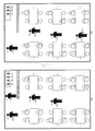
- FIG. 9 is a conceptual diagram showing an example of the inside of a store.
- a pair of one payment processing terminal Tn and one card information processing terminal Rm is used.
- the payment processing terminals T1 to T4 are carried by the clerks P1 to P4, and the card information processing terminals R1 to R4 are collected on a table, for example, at a predetermined place in the store. Is placed.
- the clerk P1 selects, for example, the card information processing terminal R1 among the card information processing terminals R1 to R4.
- the store clerk P1 arrives at the table a used by the customer as shown in FIG. 9B, the clerk P1 operates the operation / display unit 4 of the payment processing terminal T1 to present the payment amount displayed on the screen to the customer. Do. Then, the store clerk P1 confirms the settlement method to the customer, and receives the customer's settlement card CA.
- the settlement processing terminal T1 establishes a link by pairing with each of the card information processing terminals R1 to R4, and the card information processing terminal R1 communicates with each of the settlement processing terminals T1 to T4. It is assumed that the link is established by pairing.
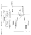
- FIG. 10 is a sequence diagram showing an example of the operation of the settlement system SS when the settlement method is credit settlement.
- the second near-field wireless communication unit 2 of the processing terminal T1 and the second near-field wireless communication unit 2 of the card information processing terminal R1 mutually detect each other, establish non-contact proximity communication, and exchange mutual identification information.
- the near-field communication detection unit 72 of the payment processing terminal T1 acquires the identification information of the card information processing terminal R1, and detects that the card information processing terminal R1 is in the second communicable range (step S101). .
- the communication control unit 73 of the payment processing terminal T1 maintains identification of the link with each of the card information processing terminals R1 to R4, and identifies the identification information of the card information processing terminal R1 detected in step S101,
- the card information processing terminals R2 to R4 are set as communication restriction parties using the communication party list (step S102). Such communication restriction setting is maintained even when the payment processing terminal T1 and the card information processing terminal R1 are out of the second communicable range of each other.
- the close-proximity communication detection unit 72 of the card information processing terminal R1 acquires the identification information of the payment processing terminal T1, and detects that the payment processing terminal T1 is in the second communicable range (step S111).
- the communication control unit 73 of the card information processing terminal R1 maintains the establishment of the link with each of the payment processing terminals T1 to T4, while identifying information of the payment processing terminal T1 detected in step S111, and The payment processing terminals T2 to T4 are set as communication restriction parties using the communication party list (step S112).
- the store clerk P1 can also bring the payment processing terminal T1 close to the card information processing terminal R1 placed on the table, for example, before bringing out the card information processing terminal R1.
- the payment processing terminal T1 detects that the card information processing terminal R1 has entered the second communicable range
- the amount of remaining power of the battery 6 of the card information processing terminal R1 is, for example, the second If the acquired remaining power amount obtained by the short distance wireless communication is less than the threshold value, it may be informed that the remaining power amount of the battery 6 of the card information processing terminal R1 is small.
- the clerk P1 can use the card information processing terminal Rm whose remaining power amount other than the card information processing terminal R1 is equal to or more than the threshold value for settlement.
- the clerk P1 inserts the payment card CA (a credit card in the example of FIG. 10) received from the customer into the card insertion portion of the card information processing terminal R1, and the personal identification number from the operation / display unit 4 of the card information processing terminal R1.
- the card information processing terminal R1 authenticates the settlement card CA in accordance with the input password, and when the authentication is successful, contact communication is established between the card information processing terminal R1 and the IC chip of the settlement card CA. .
- the processing unit 71 of the settlement processing terminal T1 receives the operation instruction signal. In response, the settlement process is started.
- the processing unit 71 of the settlement processing terminal T1 When the settlement process is started, the processing unit 71 of the settlement processing terminal T1 generates command data indicating a read command according to the operation instruction signal, and passes the generated command data to the communication control unit 73. Then, the communication control unit 73 of the payment processing terminal T1 identifies the card information processing terminal R1 as the communication partner whose communication restriction is not set from the communication partner list (step S103). The identification information of the card information processing terminal R1 thus identified and the command data indicating the read command are output to the first short distance wireless communication unit 1. Then, the first short distance wireless communication unit 1 of the payment processing terminal T1 transmits command data indicating the read command output from the communication control unit 73 to the card information processing terminal R1 by the first short distance wireless communication.
- the command data transmitted from the payment processing terminal T1 by the first short distance wireless communication is received by the first short distance wireless communication unit 1 of the card information processing terminal R1, and sent to the communication control unit 73 of the card information processing terminal R1. It is output.
- the communication control unit 73 of the card information processing terminal R1 determines whether the transmission source of the received command data is the communication restricted party based on the communication party list (step S113). In the example of FIG. 10, since the transmission source of the received command data is the payment processing terminal T1, it is determined that the transmission source of the received command data is not the communication restriction party (step S113: NO).
- the command data is passed to the processing unit 71 of the card information processing terminal R1.
- step S114 the processing unit 71 of the card information processing terminal R1 executes the card information processing in response to the read command indicated by the received command data, whereby the settlement card CA is processed via the contact communication interface unit.
- Command data indicating a read command.
- the IC chip of the payment card CA reads the card information from the non-volatile memory according to the read command indicated by the received command data, and transmits response data including the read card information to the card information processing terminal R1.
- the card information includes the credit card number, the name of the person to be issued the credit card, the expiration date of the credit card, and the like.
- the processing unit 71 of the card information processing terminal R1 passes the response data received from the payment card CA via the contact communication interface unit to the communication control unit 73 of the card information processing terminal R1.
- the communication control unit 73 of the card information processing terminal R1 outputs, to the first short-distance wireless communication unit 1, the response data and the identification information of the payment processing terminal T1 determined not to be the communication restricted party.
- the first short distance wireless communication unit 1 of the card information processing terminal R1 transmits the response data output from the communication control unit 73 to the payment processing terminal T1 by the first short distance wireless communication.
- the response data transmitted from the card information processing terminal R1 by the first short distance wireless communication is received by the first short distance wireless communication unit 1 of the payment processing terminal T1, and the processing unit 71 receives the response data via the communication control unit 73. It is output.
- the processing unit 71 of the payment processing terminal T1 generates data indicating a credit inquiry (also referred to as authorization) request, and passes the data indicating the generated credit inquiry request to the communication control unit 73.
- the data indicating the credit inquiry request includes card information included in response data received from the card information processing terminal R1, payment amount information indicating the payment amount, and the like.
- the communication control unit 73 of the payment processing terminal T1 accesses the payment management server SE via the mobile wireless communication unit 3 and manages the data indicating the credit inquiry request via the mobile wireless communication unit 3 for payment management.
- Send to server SE credit payment management server).
- the settlement management server SE makes a credit inquiry as to whether or not credit settlement is possible, in accordance with data indicating a credit inquiry request from the settlement processing terminal T1. Then, for example, when the expiration date of the credit card has not passed and the payment amount indicated by the payment amount information does not exceed the usable amount, the payment management server SE makes data indicating credit approval success the payment processing terminal T1. Send to Thus, when the data indicating the credit approval success is received from the settlement management server SE by the settlement processing terminal T1, the settlement processing ends normally. On the other hand, for example, if the expiration date of the credit card has passed, or if the payment amount indicated by the payment amount information exceeds the available amount, data indicating credit approval failure is transmitted to the payment processing terminal T1. Thereby, the settlement process abnormally ends, and an error message is notified from the settlement processing terminal T1.
- the clerk P1 When the settlement process is completed, the clerk P1 returns the card information processing terminal R1 to the original predetermined place. Thereafter, for example, when the store clerk P2 brings out the card information processing terminal R1, the card information processing terminal R1 maintains the establishment of the link by bringing its own payment processing terminal T2 and the card information processing terminal R1 close to each other. Cancel the communication restriction setting for the payment processing terminal T2 that has been detected to be within the second communicable range, and update the communication restriction setting to set the settlement processing terminals T1, T3 and T4 as the communication restriction party (The subsequent processing is the same as in the case of the store clerk P1).
- the settlement processing terminal T1 may reset all the communication restriction settings (that is, cancel the restriction on the transmission and reception of data with all the communication restriction parties) at the timing when the settlement process ends. Furthermore, at this time, the payment processing terminal T1 may transmit command data indicating a reset instruction of communication restriction setting to the card information processing terminal R1 by the first short distance wireless communication. In this case, the card information processing terminal R1 resets all the communication restriction settings in response to the reset command indicated by the received command data, and the response processing terminal indicating the reset completion is processed by the first short-distance wireless communication processing terminal Send to T1.
- FIG. 11 is a sequence diagram showing an example of the operation of the settlement system SS in the case where the settlement method is electronic money settlement by server type prepaid type electronic money.
- steps S121 to S122 shown in FIG. 11 are the same as the processes of steps S101 to S102 shown in FIG.
- steps S131 to S132 shown in FIG. 11 is the same as the processing of steps S111 to S112 shown in FIG.
- the clerk P1 inserts the payment card CA (in the example of FIG. 11, the electronic money card) received from the customer into the card insertion portion of the card information processing terminal R1, and identifies the password from the operation / display unit 4 of the card information processing terminal R1. Have the customer enter the number.
- the card information processing terminal R1 authenticates the settlement card CA in accordance with the input password, and when the authentication is successful, contact communication is established between the card information processing terminal R1 and the IC chip of the settlement card CA. .
- the processing unit 71 of the settlement processing terminal T1 receives the operation instruction signal. In response, the settlement process is started.
- the processing unit 71 of the settlement processing terminal T1 When the settlement process is started, the processing unit 71 of the settlement processing terminal T1 generates data indicating the start of electronic money settlement, and passes the generated data indicating the start of electronic money settlement to the communication control unit 73. Then, the communication control unit 73 of the payment processing terminal T1 accesses the payment management server SE via the mobile wireless communication unit 3, and pays the data indicating the start of the electronic money payment via the mobile wireless communication unit 3. It transmits to the management server SE (electronic money payment management server).
- the management server SE electronic money payment management server
- the settlement management server SE transmits data indicating a settlement information request to the settlement processing terminal T1 according to the data indicating the start of electronic money settlement from the settlement processing terminal T1.
- the data indicating the settlement information request transmitted from the settlement management server SE is received by the mobile wireless communication unit 3 of the settlement processing terminal T1, and is output to the processing unit 71 via the communication control unit 73.
- the processing unit 71 of the payment processing terminal T1 generates command data indicating a read command according to the data indicating the payment information request, and passes the generated command data to the communication control unit 73.
- the communication control unit 73 of the payment processing terminal T1 identifies the card information processing terminal R1 as the communication partner whose communication restriction is not set from the communication partner list (step S123).
- the identification information of the card information processing terminal R1 thus identified and the command data indicating the read command are output to the first short distance wireless communication unit 1. Then, the first short distance wireless communication unit 1 of the payment processing terminal T1 transmits command data indicating the read command output from the communication control unit 73 to the card information processing terminal R1 by the first short distance wireless communication.
- the command data transmitted from the payment processing terminal T1 by the first short distance wireless communication is received by the first short distance wireless communication unit 1 of the card information processing terminal R1, and sent to the communication control unit 73 of the card information processing terminal R1. It is output.
- the communication control unit 73 of the card information processing terminal R1 determines whether the transmission source of the received command data is the communication restricted party based on the communication party list (step S133). In the example of FIG. 11, since the transmission source of the received data is the payment processing terminal T1, it is determined that the transmission source of the received command data is not the communication restriction party (step S133: NO), the received Command data is passed to the processing unit 71 of the card information processing terminal R1.
- step S134 the processing unit 71 of the card information processing terminal R1 executes the card information processing in response to the read command indicated by the received command data, whereby the settlement card CA is processed via the contact communication interface unit.
- Command data indicating a read command.
- the IC chip of the payment card CA reads the card information from the non-volatile memory according to the read command indicated by the received command data, and transmits response data including the read card information to the card information processing terminal R1.
- the card information includes an electronic money card number and the like.
- the processing unit 71 of the card information processing terminal R1 passes the response data received from the payment card CA via the contact communication interface unit to the communication control unit 73 of the card information processing terminal R1.
- the communication control unit 73 of the card information processing terminal R1 outputs, to the first short-distance wireless communication unit 1, the response data and the identification information of the payment processing terminal T1 determined not to be the communication restricted party.
- the first short distance wireless communication unit 1 of the card information processing terminal R1 transmits the response data output from the communication control unit 73 to the payment processing terminal T1 by the first short distance wireless communication.
- the response data transmitted from the card information processing terminal R1 by the first short distance wireless communication is received by the first short distance wireless communication unit 1 of the payment processing terminal T1, and the processing unit 71 receives the response data via the communication control unit 73. It is output. Then, the processing unit 71 of the payment processing terminal T1 generates data indicating a payment information response, and passes the generated data indicating the payment information response to the communication control unit 73.
- the data indicating the payment information response includes the card information included in the response data received from the card information processing terminal R1, the payment amount information indicating the payment amount, and the like. Then, the communication control unit 73 of the payment processing terminal T1 transmits data indicating the payment information response via the mobile wireless communication unit 3 to the payment management server SE via the mobile wireless communication unit 3.
- the settlement management server SE balances the electronic value of the person (owner) of the electronic money issue target (the owner) from the electronic money card number indicated by the card information included therein. To make a balance inquiry as to whether electronic money settlement is possible. Then, if the balance of the electronic value is equal to or more than the payment amount indicated by the payment amount information, the settlement management server SE reduces the balance of the electronic value by the payment amount, and data indicating a successful reduction of the electronic value It transmits to the payment processing terminal T1. Thus, when data indicating the successful reduction of the electronic value is received by the settlement processing terminal T1 from the settlement management server SE, the settlement processing ends normally.
- FIG. 11 describes the operation of the settlement system SS when the settlement method is electronic money settlement by server type prepaid type electronic money, electronic money by prepaid type electronic money of settlement value stored type
- the process is basically the same as the process of steps S121 to S123 and S131 to S134 shown in FIG.
- the payment management server SE is not used, and the payment card CA receives the balance of the electronic value according to an instruction from the card information processing terminal R1. Will be reduced by the payment amount.
- the transmission and reception of data between the payment card CA and the card information processing terminal R1 may be performed by non-contact proximity communication.
- the settlement processing terminal T1 and the card information processing terminal R1 execute an arbitrary time zone when the settlement processing terminal T1 and the card information processing terminal R1 are used for settlement.
- the first near-field wireless communication with another communication partner who does not perform the first near-field wireless communication in the given time zone while maintaining establishment of a link between each of the plurality of communication partners, respectively Transmission and reception of data by communication can be efficiently limited.
- the payment processing terminal T1 and the card information processing terminal R1 can execute quick processing, and in particular, it is possible to prevent the false recognition or confusion of the user who uses the payment processing terminal T1 and the card information processing terminal R1.
- the settlement system SS while the card information processing terminal R1 maintaining the establishment of the link with the settlement processing terminals T1 to T4 is used by the store clerk, the information processing terminal R1 to the card information processing terminals R1 to R4 is used. Under the situation where the payment processing terminal T1 maintaining the establishment of the link is carried by the store clerk P1, the card information processing terminal R1 and the payment processing terminal T1 can be obtained simply by bringing the payment processing terminal T1 and the card information processing terminal R1 close to each other. The transmission and reception of data by the first short distance wireless communication can be secured only between the
- the communication system S is applicable not only to the payment system SS but also to, for example, a security system in which a guard needs to use a pair of two communication devices C in a facility or a building.
- the short distance wireless communication method based on BT is adopted as the first short distance wireless communication method
- a wireless LAN standard such as Wi-Fi (registered trademark)
- a near field communication scheme based on ZIGBEE may be adopted.
- the near field communication system based on NFC is adopted as the second near field communication system has been described, but it is based on IrDA (Infrared Data Association) technology or TransferJet (registered trademark)
- IrDA Infrared Data Association
- TransferJet registered trademark
- the present invention is a communication system in which there is no distinction between a master device and a slave device, that is, two communication devices
- the present invention is also applicable to a communication system in which both can take the initiative in the first short distance wireless communication.
- the communication system S includes the plurality of communication devices CMm and the plurality of communication devices CSm as an example. However, one communication device CMn and the plurality of communication devices CSm are provided. Also for the communication system in which the communication device CMn establishes a link with each of the plurality of communication devices CSm and performs the first short distance wireless communication with the communication device CSm existing in the first communicable range. The invention is applicable. In this case, since each communication device CSm originally performs the first short distance wireless communication with only one communication device CMn, there is no need to perform the above-described communication restriction setting (that is, in this case, the communication device CMn Only do the above mentioned communication restriction settings).
- a plurality of communication devices CMn and one communication device CSm are provided, the plurality of communication devices CMn establish a link with one communication device CSm, and the communication devices CSm exist within the first communicable range.
- the present invention is also applicable to a communication system that performs the first short distance wireless communication among the above. In this case, since each communication device CMn originally performs the first short distance wireless communication with only one communication device CSm, there is no need to perform the above-described communication restriction setting (that is, in this case, the communication device CSm Only do the above mentioned communication restriction settings).
Landscapes
- Engineering & Computer Science (AREA)
- Computer Networks & Wireless Communication (AREA)
- Signal Processing (AREA)
- Databases & Information Systems (AREA)
- Mobile Radio Communication Systems (AREA)
- Communication Control (AREA)
Abstract
通信装置Cは、第1通信可能範囲内に存在する通信相手との間で第1近距離無線通信に必要なリンクを確立した後、当該リンクが確立された通信相手との間で第1近距離無線通信を行う第1通信部と、第1通信可能範囲よりも狭い第2通信可能範囲内に存在する通信相手との間で第2近距離無線通信を行う第2通信部と、を備える。そして、通信装置Cは、リンクが確立された複数の通信相手のうちの何れか1つの通信相手が第2通信可能範囲内に入ったことを検出した場合、リンクが確立された複数の通信相手のそれぞれとの間の当該リンクの確立を維持しつつ、第2通信可能範囲内に入ったことが検出された通信相手以外の通信相手との間の第1近距離無線通信によるデータの送受信を制限する。
Description
本発明は、1つの通信装置が複数の通信装置のそれぞれとの間で近距離無線通信を行うことが可能な通信システムの技術分野に関する。
従来から、近距離無線通信規格として、Bluetooth(登録商標)(以下、「BT」と称する)やWi-Fi(登録商標)等の無線LAN規格が知られている。例えば、BTに基づく近距離無線通信方式では、通信装置は、マスタ装置とスレーブ装置とに区分される。そして、BTに基づく近距離無線通信方式では、1つのマスタ装置と複数のスレーブ装置のそれぞれとの間でペアリングによりリンクが確立(マルチポイント接続)された後、マスタ装置はリンクが確立された複数のスレーブ装置との間で同時に近距離無線通信を行うことが可能になっている。ここで、ペアリングとは、マスタ装置とスレーブ装置との間のリンクの確立手順(換言すすると、マスタ装置とスレーブ装置とを関連付ける手順)をいう。そして、一旦ペアリングが行われると、ペアリングが解除されない限り、例えばマスタ装置またはスレーブ装置の電源が切られても、当該リンクの確立は維持され、マスタ装置とスレーブ装置とが通信可能範囲(通信可能圏)内にあれば近距離無線通信を直ちに行うことができる。なお、特許文献1には、例えば、赤外線通信方式やNFC(Near field radio communication)に基づく非接触近接通信方式を用いて、無線LANやBTの認証情報を伝送し、その認証情報を用いて無線LANやBTの認証設定を行うことで、ユーザは、認証処理や設定処理について意識することなく、自動的に無線LANやBTに係る通信機能を利用できる技術(ハンドオーバー技術)が開示されている。
ところで、上述したように、近距離無線通信において、複数の通信装置間でリンクの確立が維持されることはユーザの手間等を削減できるので効率的である。しかしながら、1つの通信装置(例えば、マスタ装置)と複数の通信装置(例えば、スレーブ装置)のそれぞれとの間でのリンク確立中の任意の時間帯において、特定の2台の通信装置間に限り近距離無線通信を行わせることが必要な場合がある。このような場合の例として、当該2台の通信装置のうち少なくとも何れか一方の通信装置において特に迅速な処理が求められる場合、当該通信装置を使用するユーザの誤認や混乱を特に防ぐことが求められる場合、或いは、当該2台の通信装置でやり取りされる情報の流出を防ぐことが必要な場合などがある。このような場合、上記任意の時間帯において、上記2台の通信装置のとの間で近距離無線通信を行わない他の通信装置の近距離無線通信機能はユーザの操作によりオフにすることが可能である。しかし、このような操作は効率的でなく、このことは、特定の通信装置との間でリンクが確立している他の通信装置の数が多くなればなるほど顕著になる。
そこで、本発明は、上記点等に鑑みてなされたものであり、特定の通信装置と複数の通信装置(通信相手)のそれぞれとの間のリンクの確立を維持しつつ、任意の時間帯で近距離無線通信を行わない他の通信装置との間の当該近距離無線通信によるデータの送受信を効率良く制限することが可能な通信装置、通信方法、及び通信処理プログラムを提供することを課題とする。
上記課題を解決するために、請求項1に記載の発明は、第1通信可能範囲内に存在する通信相手との間で第1近距離無線通信に必要なリンクを確立した後、当該リンクが確立された通信相手との間で前記第1近距離無線通信を行う第1通信部と、前記第1通信可能範囲よりも狭い第2通信可能範囲内に存在する通信相手との間で第2近距離無線通信を行う第2通信部と、前記リンクが確立された複数の通信相手のうちの何れか1つの通信相手が前記第2通信可能範囲内に入ったことを検出する検出部と、前記検出部により、前記通信相手が前記第2通信可能範囲内に入ったことが検出された場合、前記リンクが確立された複数の通信相手のそれぞれとの間の当該リンクの確立を維持しつつ、前記第2通信可能範囲内に入ったことが検出された通信相手以外の通信相手との間の前記第1近距離無線通信によるデータの送受信を制限する通信制御部と、を備えることを特徴とする。
この発明によれば、特定の通信装置と複数の通信相手のそれぞれとの間のリンクの確立を維持しつつ、任意の時間帯で第1近距離無線通信を行わない他の通信相手との間の第1近距離無線通信によるデータの送受信を効率良く制限することができる。
請求項2に記載の発明は、請求項1に記載の通信装置において、前記検出部により、前記第1近距離無線通信によるデータの送受信が制限された前記通信相手が前記第2通信可能範囲内に入ったことが更に検出された場合、前記通信制御部は、前記リンクが確立された複数の通信相手のそれぞれとの間の当該リンクの確立を維持しつつ、前記第2通信可能範囲内に入ったことが更に検出された通信相手との間の前記データの送受信の制限を解除し、且つ、前記データの送受信の制限が解除された通信相手以外の通信相手との間の前記第1近距離無線通信によるデータの送受信を制限することを特徴とする。
この発明によれば、特定の通信装置において、第1近距離無線通信によるデータの送受信を制限しない通信相手を迅速かつ、効率良く切り替えることができる。
請求項3に記載の発明は、請求項1または2に記載の通信装置において、前記通信制御部は、前記第1近距離無線通信によるデータの送受信が制限された通信相手からの前記第1近距離無線通信による所定の命令に応じないことを特徴とする。
この発明によれば、特定の通信装置において、第1近距離無線通信によるデータの送受信が制限された通信相手から第1近距離無線通信により所定の命令を示すデータが受信された場合であっても、当該命令に応じないことで、当該通信相手との間の第1近距離無線通信によるデータの送受信を効率良く制限することができる。
請求項4に記載の発明は、請求項1乃至3の何れか一項に記載の通信装置において、前記通信装置は、当該通信装置が備える各部に電力を供給するバッテリーを備え、前記リンクが確立された複数の通信相手の何れとも前記第1近距離無線通信が行われない状態が所定時間継続した場合、前記通信制御部は、前記リンクが確立された複数の通信相手のそれぞれとの間の当該リンクの確立を維持しつつ、前記バッテリーの電力消費モードを通常モードから省電力モードに切り替え、その後、前記検出部により、前記リンクが確立された複数の通信相手のうちの何れか1つの通信相手が前記第2通信可能範囲内に入ったことが検出された場合、前記通信制御部は、前記バッテリーの電力消費モードを、省電力モードから通常モードに切り替え、前記第2通信可能範囲内に入ったことが検出された通信相手以外の通信相手との間の前記第1近距離無線通信によるデータの送受信を制限することを特徴とすることを特徴とする。
この発明によれば、特定の通信装置において、バッテリーの電力消費を抑えつつ、任意の時間帯で第1近距離無線通信を行わない他の通信相手との間の第1近距離無線通信によるデータの送受信を効率良く制限することができる。
請求項5に記載の発明は、請求項4に記載の通信装置において、前記リンクが確立された複数の通信相手の何れとも前記第1近距離無線通信が行われない状態が所定時間継続した場合、前記通信制御部は、前記リンクが確立された複数の通信相手のそれぞれとの間の当該リンクの確立を維持しつつ、前記バッテリーの電力消費モードを通常モードから省電力モードに切り替えるとともに、前記第1近距離無線通信によるデータの送受信が制限された全ての前記通信相手との間の当該制限を解除することを特徴とする。
この発明によれば、特定の通信装置において、第1近距離無線通信によるデータの送受信の制限を効率良くリセットすることができる。
請求項6に記載の発明は、請求項1乃至5の何れか一項に記載の通信装置において、前記検出部により、前記通信相手が前記第2通信可能範囲内に入ったことが検出された場合、前記通信制御部は、前記第2通信可能範囲内に入ったことが検出された通信相手のバッテリーの残電力量を取得し、取得された残電力量が閾値未満である場合、当該通信相手のバッテリーの残電力量が少ないことを報知することを特徴とする。
この発明によれば、特定の通信装置において、第1近距離無線通信によるデータの送受信の制限しない通信相手として、バッテリーの残電力量が閾値未満である通信相手を除外することが可能となる。
請求項7に記載の発明は、コンピュータにより実行される通信方法であって、第1通信可能範囲内に存在する通信相手との間で第1近距離無線通信に必要なリンクを確立した後、当該リンクが確立された通信相手との間で前記第1近距離無線通信を行うステップと、前記第1通信可能範囲よりも狭い第2通信可能範囲内に存在する通信相手との間で第2近距離無線通信を行うステップと、前記リンクが確立された複数の通信相手のうちの何れか1つの通信相手が前記第2通信可能範囲内に入ったことを検出するステップと、前記通信相手が前記第2通信可能範囲内に入ったことが検出された場合、前記リンクが確立された複数の通信相手のそれぞれとの間の当該リンクの確立を維持しつつ、前記第2通信可能範囲内に入ったことが検出された通信相手以外の通信相手との間の前記第1近距離無線通信によるデータの送受信を制限するステップと、を含むことを特徴とする。
請求項8に記載の発明は、第1通信可能範囲内に存在する通信相手との間で第1近距離無線通信に必要なリンクを確立した後、当該リンクが確立された通信相手との間で前記第1近距離無線通信を行う第1通信部と、前記第1通信可能範囲よりも狭い第2通信可能範囲内に存在する通信相手との間で第2近距離無線通信を行う第2通信部と、を備えるコンピュータを、前記リンクが確立された複数の通信相手のうちの何れか1つの通信相手が前記第2通信可能範囲内に入ったことを検出する検出部と、前記検出部により、前記通信相手が前記第2通信可能範囲内に入ったことが検出された場合、前記リンクが確立された複数の通信相手のそれぞれとの間の当該リンクの確立を維持しつつ、前記第2通信可能範囲内に入ったことが検出された通信相手以外の通信相手との間の前記第1近距離無線通信によるデータの送受信を制限する通信制御部として機能させることを特徴とする。
本発明によれば、特定の通信装置と複数の通信相手のそれぞれとの間のリンクの確立を維持しつつ、任意の時間帯で近距離無線通信を行わない他の通信相手の第1近距離無線通信によるデータの送受信を効率良く制限することができる。
以下、図面を参照して本発明の実施形態について説明する。以下に説明する実施の形態は、1つの通信装置が複数の通信装置のそれぞれとの間で近距離無線通信を行うことが可能な通信システムに対して本発明を適用した場合の実施形態である。
[1.通信システムSの概要]
先ず、図1を参照して、通信システムSの概要について説明する。図1は、通信システムSの概要構成の一例を示す図である。図1の例では、通信システムSは、通信装置CMn(n=1,2,3,4)、及び通信装置CSm(m=1,2,3,4)等を備えて構成されている。なお、通信装置CMnと、通信装置CSmとを総称して、通信装置Cという。通信装置Cの数は、特に限定されるものではない。また、通信装置CMnの通信相手は通信装置CSmであり、通信装置CSmの通信相手は通信装置CMnである。
先ず、図1を参照して、通信システムSの概要について説明する。図1は、通信システムSの概要構成の一例を示す図である。図1の例では、通信システムSは、通信装置CMn(n=1,2,3,4)、及び通信装置CSm(m=1,2,3,4)等を備えて構成されている。なお、通信装置CMnと、通信装置CSmとを総称して、通信装置Cという。通信装置Cの数は、特に限定されるものではない。また、通信装置CMnの通信相手は通信装置CSmであり、通信装置CSmの通信相手は通信装置CMnである。
通信装置Cは、通信可能範囲(言い換えれば、通信可能距離)が互いに異なる複数種類の近距離無線通信方式を採用する。例えば、通信装置Cは、BTに基づく近距離無線通信(以下、「第1近距離無線通信」という)方式と、NFCに基づく近距離無線通信(以下、「第2近距離無線通信(非接触近接通信)」という)方式とを採用する。第1近距離無線通信方式は、2.4GHz帯を利用した無線通信技術であり、その通信可能距離(最大)は、10m~100mの間に設定(例えば、10m程度に設定)される。第1近距離無線通信方式では、例えば、周波数帯域幅が1MHzのチャネルが79個設定され、1秒間に1600回チャネルを切り換える周波数ホッピング方式のスペクトラム拡散技術が採用される。一方、第2近距離無線通信方式は、13.56MHz帯を利用した無線通信(非接触近接通信)技術(RFID(Radio Frequency Identification)技術の一種)であり、その通信可能距離(最大)は、数cm程度である。そのため、NFCに基づく通信可能範囲(以下、「第2通信可能範囲」という)は、BTに基づく通信可能範囲(以下、「第1通信可能範囲」という)よりも狭い。
通信装置CMnは、第1近距離無線通信方式におけるマスタ装置に相当する。一方、通信装置CSmは、第1近距離無線通信方式におけるスレーブ装置に相当する。通信装置CMnは、処理内容に応じて周波数ホッピングパターンを決定し、通信装置CSmは、通信装置CMnに制御される(つまり、第1近距離無線通信の主導権は、マスタ装置が持つ)。図1の例では、それぞれの通信装置CMnは、それぞれの通信装置CSmとの間でペアリングによりリンクを確立(マルチポイント接続)しており、第1通信可能範囲内に存在する通信装置CSmとの間で第1近距離無線通信を行う。本実施形態では、少なくとも2つ以上の通信装置CSmが、1つの通信装置CMnの第1通信可能範囲内に存在している(つまり、入っている)ことを想定している。例えば、通信装置CM1は、通信装置CS1~CS4のそれぞれとの間で上記リンク(つまり、第1近距離無線通信に必要なリンク)を確立している。そして、通信装置CS1~CS4のうち、例えば通信装置CS1,CS2,及びCS3が通信装置CM1の第1通信可能範囲内に存在している場合、通信装置CM1は、通信装置CS1,CS2,及びCS3のそれぞれとの間で同時に第1近距離無線通信を行うことができる。
また、通信装置CMnは、第2通信可能範囲内に存在する通信装置CSmとの間で第2近距離無線通信(非接触近接通信)を行う。本実施形態では、1つの通信装置CMnの第2通信可能範囲内に、1つの通信装置CSmが入ってくることを想定している。例えば、通信装置CM1は、上記リンクが確立された通信装置CS1~CS4のうち、通信装置CS1が第2通信可能範囲(つまり、通信装置CM1の第2通信可能範囲)内に入ったことを検出した場合、上記リンクが確立された通信装置CS1~CS4のそれぞれとの間の当該リンクの確立を維持しつつ、第2通信可能範囲内に入ったことが検出された通信装置CS1以外の通信装置CS2~CS4との間の第1近距離無線通信によるデータの送受信を制限する。例えば、通信装置CS2~CS4を通信制限相手として設定する通信制限設定が実行される。このとき、通信装置CS1は、通信装置CM1が第2通信可能範囲(つまり、通信装置CS1の第2通信可能範囲)内に入ったことを検出し、上記リンクが確立された通信装置CM1~CM4のそれぞれとの間の当該リンクの確立を維持しつつ、第2通信可能範囲内に入ったことが検出された通信装置CM1以外の通信装置CM2~CM4との間の第1近距離無線通信によるデータの送受信を制限する。例えば、通信装置CM2~CM4を通信制限相手として設定する通信制限設定が実行される。これにより、任意の時間帯において、特定の2台の通信装置CM1と通信装置CS1間に限り、第1近距離無線通信を行わせることが可能となる。
ここで、「第1近距離無線通信によるデータの送受信を制限する」ことの例として、通信制限相手に対して第1近距離無線通信により正規データを送信しないことが挙げられる。正規データとは、通信装置Cにおける処理に必要なデータ(換言すると、正規データは、当該処理を正常に進行させるためのデータ)である。この場合の正規データの例として、通信相手に対するコマンドデータ(所定の命令を示すデータ)が挙げられる。コマンドデータには、処理対象となるデータ(例えば、処理前または処理後のデータ)が含まれる場合もある。これにより、例えば、通信装置CM1は、第1通信可能範囲内に存在する通信装置CS1のみに対して、第1近距離無線通信によりコマンドデータを送信する。換言すると、通信装置CM1は、通信制限相手である通信装置CS2~CS4が第1通信可能範囲内に存在する場合であっても、当該通信制限相手へは第1近距離無線通信によりコマンドデータを送信しない。なお、正規データでないデータの例として、エラーメッセージデータがあり、これは、第1近距離無線通信による送受信が制限されなくてもよい。
また、「第1近距離無線通信によるデータの送受信を制限する」ことの別の例として、通信制限相手から第1近距離無線通信により送信された正規データを受信しないことが挙げられる。「正規データを受信しない」とは、例えば、通信装置Cにインストールされたアプリケーション(ソフトウェア)が正規データを受け取らない(または破棄する)ことを意味する。この場合の正規データの例として、通信制限相手からのコマンドデータが挙げられる。これにより、例えば、通信装置CS1は、通信制限相手である通信装置CM2~CM4から第1近距離無線通信によりコマンドデータが受信(BTに基づく近距離無線通信機能により受信)された場合であっても、その命令に応じず、その命令に対するレスポンスデータを返信しない(或いは、その命令に応じられないことを示すエラーメッセージデータを返信する)。換言すると、通信装置CS1は、通信制限相手でない通信装置CM1から第1近距離無線通信によりコマンドデータが受信された場合に限り、その命令に応じて処理を行い、その命令に対するレスポンスデータ(例えば、処理結果を示すレスポンスデータ)を返信する。これにより、通信装置CS1は、通信制限相手である通信装置CM2~CM4との間の第1近距離無線通信によるデータの送受信を効率良く制限することができる。
なお、ペアリングによるリンクの確立後、第1近距離無線通信によるデータの送受信の前に論理的通信路(コネクション)の確立が行われる場合には、「第1近距離無線通信によるデータの送受信を制限する」ことは、当該論理的通信路の確立の拒否であってもよい。
さらに、例えば、通信装置CM1は、第1近距離無線通信によるデータの送受信が制限された通信装置CS2が第2通信可能範囲(つまり、通信装置CM1の第2通信可能範囲)内に入ったことを更に検出した場合、上記リンクが確立された通信装置CS1~CS4のそれぞれとの間の当該リンクの確立を維持しつつ、第2通信可能範囲内に入ったことが更に検出された通信装置CS2との間のデータの送受信の制限を解除(例えば、通信装置CS2の通信制限設定を解除)し、且つ、データの送受信の制限が解除された通信装置CS2以外の通信装置CS1及びCS3~CS4との間の第1近距離無線通信によるデータの送受信を制限する。これにより、通信装置CM1は、第1近距離無線通信によるデータの送受信を制限しない通信相手を迅速かつ、効率良く切り替えることができる。このとき、通信装置CS2は、通信装置CM1が第2通信可能範囲(つまり、通信装置CS2の第2通信可能範囲)内に入ったことを検出し、上記リンクが確立された通信装置CM1~CM4のそれぞれとの間の当該リンクの確立を維持しつつ、第2通信可能範囲内に入ったことが検出された通信装置CM1以外の通信装置CM2~CM4との間の第1近距離無線通信によるデータの送受信を制限する。
なお、通信装置CS2により通信装置CM1が第2通信可能範囲内に入ったことが検出されたときに既に通信制限設定(例えば、通信装置CM1~CM3が通信制限相手として設定)が行われている場合、通信装置CS2は、上記リンクが確立された通信装置CM1~CM4のそれぞれとの間の当該リンクの確立を維持しつつ、第2通信可能範囲内に入ったことが更に検出された通信装置CM1との間のデータの送受信の制限を解除(例えば、通信装置CM1の通信制限設定を解除)し、且つ、データの送受信の制限が解除された通信装置CM1以外の通信装置CM2~CM4との間の第1近距離無線通信によるデータの送受信を制限する。
[2.通信装置Cの構成及び機能]
次に、図2等を参照して、通信装置Cの構成及び機能について説明する。図2は、通信装置Cの概要構成の一例を示す図である。図2に示すように、通信装置Cは、第1近距離無線通信部1、第2近距離無線通信部2、移動体無線通信部3、操作・表示部4、記憶部5、バッテリー6、及びこれらの各部を制御する制御部7等を備えて構成される。なお、通信装置Cは、音声処理部及びスピーカを備えてもよい。第1近距離無線通信部1は、本発明における第1通信部の一例であり、第2近距離無線通信部2、本発明における第1通信部の一例である。
次に、図2等を参照して、通信装置Cの構成及び機能について説明する。図2は、通信装置Cの概要構成の一例を示す図である。図2に示すように、通信装置Cは、第1近距離無線通信部1、第2近距離無線通信部2、移動体無線通信部3、操作・表示部4、記憶部5、バッテリー6、及びこれらの各部を制御する制御部7等を備えて構成される。なお、通信装置Cは、音声処理部及びスピーカを備えてもよい。第1近距離無線通信部1は、本発明における第1通信部の一例であり、第2近距離無線通信部2、本発明における第1通信部の一例である。
第1近距離無線通信部1は、第1近距離無線通信用のアンテナ(図示せず)に接続されており、第1近距離無線通信部1内には、それぞれの通信装置Cの第1近距離無線通信部1毎に固有のデバイスアドレスが予め保存されている。第1近距離無線通信部1は、BTに基づく近距離無線通信機能を有し、第1通信可能範囲内に存在する通信相手の第1近距離無線通信部1との間でペアリングによりリンクを確立した後、当該リンクが確立された通信相手の第1近距離無線通信部1との間で第1近距離無線通信を行う。
このペアリングでは、通信装置CMnと通信装置CSmとの双方の第1近距離無線通信部1間で、互いの認証情報(公開鍵等)が交換されて相互認証が行われ、当該相互認証が成功すると、共有キー(リンクキーまたはLong Term Key)が生成される。そして、生成された共有キーは、通信装置CMnと通信装置CSmとの双方の第1近距離無線通信部1内に保存(ボンディング)される。このとき、双方の第1近距離無線通信部1内には、通信相手の第1近距離無線通信部1のデバイスアドレスが共通キーに対応付けられて保存される。こうして保存された共有キーは、ペアリング後の第1近距離無線通信で伝送されるパケットのデータ(パケットのペイロード部におけるデータ)の暗号化または復号に用いられる。なお、ペアリングされる通信装置CMnと通信装置CSmとの双方の第1近距離無線通信部1内には、共通のプロファイル(第1近距離無線通信のプロトコルを規定)が保存される。このようなプロファイルの例として、GAP(Generic Access Profile)、FTP (File Transfer Profile)、GATT(Generic Attribute Profile)などが挙げられる。
第2近距離無線通信部2は、第2近距離無線通信用のアンテナ(図示せず)に接続される。第2近距離無線通信部2は、NFCに基づく近距離無線通信機能を有し、第1通信可能範囲よりも狭い第2通信可能範囲内に存在する通信相手の第2近距離無線通信部2との間で第2近距離無線通信(非接触近接通信)を行う。本実施形態では、第2近距離無線通信部2は、P2P(Peer-to-Peer)モードに設定されるとよい。例えば、通信装置CMnと通信装置CSmの互いの第2通信可能範囲内に入った場合、通信装置CMnの第2近距離無線通信部2と通信装置CSmの第2近距離無線通信部2とは相互に検出して非接触近接通信を確立し、互いの識別情報を交換する。識別情報の交換は、例えば、NDEF(NFC Data Exchange Format)で定義されたタグに識別情報を書き込んでおくことで実現できる。そして、例えば、通信装置CMnの第2近距離無線通信部2により取得された識別情報(つまり、通信装置CSmの識別情報)は、通信装置CMnの制御部7に出力される。一方、通信装置CSmの第2近距離無線通信部2により取得された識別情報(つまり、通信装置CMnの識別情報)は、通信装置CSmの制御部7に出力される。なお、通信装置Cの識別情報の例として、通信装置Cに搭載された第1近距離無線通信部1のデバイスアドレスが挙げられる。ただし、通信装置Cの識別情報は、通信装置CのMACアドレスなど、通信装置Cを一意に特定可能な情報であれば、その他の情報であってもよく、この場合、このような情報は、第1近距離無線通信部1のデバイスアドレスに紐づけられる。
移動体無線通信部3は、移動体無線通信用のアンテナ(図示せず)に接続される。移動体無線通信部3は、移動体通信ネットワークを利用した無線通信機能を有する。移動体通信ネットワークは、例えば、電話用回線交換ネットワーク、及びインターネットに接続するためのデータ通信用パケット交換ネットワークを含む。移動体無線通信部3は、アンテナ(図示せず)を介して、最寄りの基地局との間で無線通信を行い、当該基地局及び移動体通信ネットワークを介して所定のサーバとの間で通信を行う。
操作・表示部4は、通信装置Cのユーザの指やペン等による操作指示を受け付ける入力機能と、情報を表示する画面を有するタッチパネルとを備える。操作・表示部4は、ユーザからの操作指示を受け付け、その操作指示に応じた操作指示信号を制御部7へ出力する。
記憶部5は、例えば不揮発性メモリから構成され、OS(Operating System),及びアプリケーション等を格納する。アプリケーションは、アプリケーションプログラム(本発明の通信処理プログラムを含む)等をメモリに展開して実行可能な状態にインストールされたアプリケーションインスタンスである。なお、アプリケーションプログラムは、所定のサーバから通信装置Cにダウンロードされてもよいし、CD、DVDなどの記録媒体に記録(コンピュータにより読み取り可能に記録)されており、当該記録媒体から読み込まれて記憶部6に格納されるようにしてもよい。
バッテリー6は、通信装置Cの電源であり、通信装置Cを動作させるための電力を外部から充電可能になっている。バッテリー6は、制御部7の制御の下、通信装置Cの各部に電力を供給する。なお、バッテリー6の電力消費状況は、制御部7により監視される。例えば、制御部7は、バッテリー6の出力電流値に基づいて現在の電流消費率を測定することによって電力消費状況を監視する。また、制御部7は、バッテリー6の残電力量(例えば、バッテリー残存率)を監視する。また、バッテリー6は、制御部7の制御の下、電力消費モードを、通常モードから省電力モードに切り替えられる。省電力モードでは、例えば、操作・表示部4における画面の明るさが通常モードに比べて暗く設定され、スリープ状態に至るまでの時間が通常モードに比べて短く設定される。なお、省電力モードでは、バッテリー6からの制御部7以外への電源供給をオフにしてもよい。
制御部7は、CPU(Central Processing Unit),ROM(Read Only Memory),及びRAM(Random Access Memory)等を備える。制御部7(制御部7内のプロセッサ)は、OS上で実行されるアプリケーションにしたがって、処理部71、近接通信検出部72、及び通信制御部73等として機能する。また、制御部7は、バッテリー6の電源供給のオンオフ制御(つまり、電源の入切制御)を行う。図3は、制御部7の機能ブロック例を示す図である。なお、近接通信検出部72は、本発明における検出部の一例であり、通信制御部73は、本発明における通信制御部の一例である。なお、第2近距離無線通信部2が本発明における検出部であってもよい。
処理部71は、操作・表示部4からの操作指示信号に応じて、或いは、第1近距離無線通信部1、第2近距離無線通信部2、または移動体無線通信部3により受信されたデータ(例えば、コマンドデータ、またはレスポンスデータ)に応じて所定の処理を実行する。なお、第1近距離無線通信部1、第2近距離無線通信部2、または移動体無線通信部3により受信されたデータは、通信制御部73を介して処理部71に出力される。また、処理部71により処理されたデータは、通信制御部73を介して、第1近距離無線通信部1、第2近距離無線通信部2、または移動体無線通信部3に出力される。
近接通信検出部72は、第2近距離無線通信部2からの識別情報を取得することで、当該識別情報に対応する通信相手(つまり、上記リンクが確立された複数の通信相手のうちの何れか1つの通信相手)が第2通信可能範囲内に入ったことを検出する。なお、近接通信検出部72により取得された識別情報は、通信制御部73に渡される。
通信制御部73は、第1近距離無線通信部1、第2近距離無線通信部2、及び移動体無線通信部3のそれぞれによるデータの送受信を制御する。なお、通信制御部73は、操作・表示部4からの操作指示信号にしたがって、ペアリングの実行、ペアリングの解除(ペアリングにより生成された共有キーの削除)、BTに基づく近距離無線通信機能のオンオフ、及びNFCに基づく近距離無線通信機能のオンオフなどの制御を行うことが可能になっている。
また、通信制御部73は、近接通信検出部72により、上記通信相手が第2通信可能範囲内に入ったことが検出された場合、上記リンクが確立された複数の通信相手のそれぞれとの間の当該リンクの確立を維持(つまり、ペアリングの解除を行わないことで上記リンクの確立を維持)しつつ、第2通信可能範囲内に入ったことが検出された通信相手(つまり、取得された識別情報に対応する通信相手)以外の通信相手との間の第1近距離無線通信によるデータの送受信を制限する。例えば、通信制御部73は、上記リンクが確立された通信相手の情報を登録する通信相手リストと、第2近距離無線通信部2を通じて取得された識別情報とを用いて、通信制限相手を設定する通信制限設定を行う。このような通信相手リストは、例えば、制御部7のRAMに格納される。
図4(A)は、通信装置CM1の制御部7が持つ通信相手リストの一例を示す図であり、図4(B)は、通信装置CS1の制御部7が持つ通信相手リストの一例を示す図である。図4(A)に示す通信相手リストには、通信装置CM1との間で上記リンクが確立された通信装置CS1~CS4のそれぞれの識別情報(通信相手の識別情報)と、通信制限有無値とが対応付けられて登録されている。なお、通信相手リストに登録される識別情報は、ペアリングの際に取得される。図4(A)に示す通信相手リストでは、通信装置CS2~CS4が通信制限相手として通信制限設定(通信制限有無値=1(有))されている。つまり、この例では、通信装置CM1の通信制御部73は、第2通信可能範囲内に入ったことが検出された通信装置CS1の識別情報(つまり、取得された識別情報)以外の識別情報に対応付けられた通信制限有無値を“1”にすることで通信制限設定を行っている。一方、図4(B)に示す通信相手リストには、通信装置CS1との間で上記リンクが確立された通信装置CM1~CM4のそれぞれの識別情報と、通信制限有無値とが対応付けられて登録されている。図4(B)に示す通信相手リストでは、通信装置CM2~CM4が通信制限相手として通信制限設定(通信制限有無値=1(有))されている。
また、通信制御部73は、通信制限設定後に、近接通信検出部72により、通信制限設定された通信制限相手が第2通信可能範囲内に入ったことが更に検出された場合、上記リンクが確立された複数の通信相手(通信制限相手も含む)のそれぞれとの間の当該リンクの確立を維持しつつ、第2通信可能範囲内に入ったことが更に検出された通信制限相手との間のデータの送受信の制限を解除(つまり、通信制限相手に対する通信制限設定を解除)し、且つ、当該データの送受信の制限が解除された通信相手以外の通信相手との間の第1近距離無線通信によるデータの送受信を制限する。例えば、通信制御部73は、上記通信相手リストを用いて、通信制限設定の更新を行う。
図5は、通信装置CM1の制御部7が持つ通信相手リストの更新の一例を示す図である。図5(A)に示す通信相手リストは、図5(B)に示すように、通信制限設定が更新されている。つまり、この例では、通信装置CM1の通信制御部73は、第2通信可能範囲内に入ったことが更に検出された通信装置CS2の識別情報に対応付けられた通信制限有無値“1”を“0”に変更(つまり、当該制限を解除)し、且つ、当該通信装置CS2の識別情報以外の識別情報に対応付けられた通信制限有無値を“1”にすることで通信制限設定の更新を行っている。なお、この更新には、通信装置CS3及びCS4のように、通信制限有無値が“1”のまま維持されるものも含まれる。
そして、通信制御部73は、第1近距離無線通信によりデータを送信する際には、通信相手リストから、通信制限設定されていない通信相手を特定し(つまり、当該通信相手の識別情報(例えば、通信相手に搭載された第1近距離無線通信部1のデバイスアドレス)を特定し)、上記データと上記特定した識別情報とを第1近距離無線通信部1に出力する。これにより、第1近距離無線通信部1は、通信制御部73から出力されたデータをパケット化し、通信制御部73から出力された識別情報をパケットのヘッダ部の宛先に設定し、且つ当該ヘッダ部の送信元に、送信元である通信装置Cの識別情報を設定し、上記リンクが確立され且つ第1通信可能範囲内に存在する通信相手へ送信する。この場合、第1近距離無線通信部1により送信されるパケットのペイロード部におけるデータは、通信制御部73から出力された識別情報に対応付けられた共有キーにより暗号化されて送信される。
一方、通信制御部73は、第1近距離無線通信部1により受信されたパケットのデータを入力した場合には、通信相手リストに基づいて、当該データの送信元が通信制限相手であるか否かを判定する。換言すると、当該パケットのヘッダ部の送信元に設定された識別情報に対応する通信相手が通信制限設定されているか否かが判定される。例えば、通信相手リストにおいて、当該パケットのヘッダ部の送信元に設定された識別情報に対して通信制限有無値が“1”が対応付けられている場合、通信相手が通信制限設定されていると判定される。この場合、通信制御部73は、受信されたパケットのデータを、処理部71には渡さず、エラー処理(例えば、当該データを破棄)を行う。一方、通信制御部73は、通信相手が通信制限設定されていないと判定した場合、受信されたパケットのデータを、処理部71には渡して処理させる。
なお、通信制御部73は、上記リンクが確立された複数の通信相手の何れとも第1近距離無線通信が行われない状態の継続時間をタイマーにより計測し、第1近距離無線通信が行われない状態が所定時間継続した場合、上記リンクが確立された複数の通信相手のそれぞれとの間の当該リンクの確立を維持しつつ、バッテリー6の電力消費モードを通常モードから省電力モードに切り替えるように構成してもよい(電源供給制限)。このとき、上記リンクが確立された複数の通信相手の何れかに対して通信制限設定がなされている場合、通信制御部73は、当該通信制限設定をリセットするとよい。こうして、バッテリー6の電力消費モードが省電力モードに切り替えられた後、通信制御部73は、近接通信検出部72により、上記リンクが確立された複数の通信相手のうちの何れか1つの通信相手が第2通信可能範囲内に入ったことが検出された場合、バッテリー6の電力消費モードを、省電力モードから通常モードに切り替えるとともに、第2通信可能範囲内に入ったことが検出された通信相手以外の通信相手との間の第1近距離無線通信によるデータの送受信を制限する。
[3.通信システムSの基本動作]
次に、図6を参照して、通信システムSの基本動作について説明する。図6は、通信システムSの基本動作の一例を示すシーケンス図である。図6の例では、通信装置CM1及びCM2は、それぞれ、通信装置CS1~CS4のそれぞれのとの間でペアリングによりリンクを確立している。なお、通信装置CM3及びCM4については図示を省略しているが、通信装置CM3及びCM4は、それぞれ、通信装置CS1~CS4のそれぞれとの間でペアリングによりリンクを確立している。
次に、図6を参照して、通信システムSの基本動作について説明する。図6は、通信システムSの基本動作の一例を示すシーケンス図である。図6の例では、通信装置CM1及びCM2は、それぞれ、通信装置CS1~CS4のそれぞれのとの間でペアリングによりリンクを確立している。なお、通信装置CM3及びCM4については図示を省略しているが、通信装置CM3及びCM4は、それぞれ、通信装置CS1~CS4のそれぞれとの間でペアリングによりリンクを確立している。
図6に示すように、通信装置CM1と通信装置CS1とが近接することで互いの第2通信可能範囲内に入った場合、通信装置CM1の第2近距離無線通信部2と通信装置CS1の第2近距離無線通信部2とは相互に検出して非接触近接通信を確立し、互いの識別情報を交換する。これにより、通信装置CM1の近接通信検出部72は、通信装置CS1の識別情報を取得し、通信装置CS1が第2通信可能範囲内に入ったことを検出する(ステップS1)。次いで、通信装置CM1の通信制御部73は、通信装置CS1~CS4のそれぞれとの間の上記リンクの確立を維持しつつ、ステップS1で検出された通信装置CS1の識別情報、及び通信相手リストを用いて、通信装置CS2~CS4を通信制限相手として設定(通信制限設定)する(ステップS2)。このような通信制限設定は、通信装置CM1と通信装置CS1とが互いの第2通信可能範囲外に出た場合であっても維持される。
一方、通信装置CS1の近接通信検出部72は、通信装置CM1の識別情報を取得し、通信装置CM1が第2通信可能範囲内に入ったことを検出する(ステップS11)。次いで、通信装置CS1の通信制御部73は、通信装置CM1~CM4のそれぞれとの間の上記リンクの確立を維持しつつ、ステップS11で検出された通信装置CM1の識別情報、及び通信相手リストを用いて、通信装置CM2~CM4を通信制限相手として設定する(ステップS12)。
その後、通信装置CM1の処理部71が操作指示信号等に応じて所定の処理を実行し(図示せず)、当該処理に応じたデータ(例えば、コマンドデータ)を第1近距離無線通信により送信する場合、通信装置CM1の通信制御部73は、通信相手リストから、通信制限設定されていない通信相手として、通信装置CS1を特定する(ステップS3)。こうして特定された通信装置CS1の識別情報、及び上記処理に応じたデータは、第1近距離無線通信部1へ出力される。そして、通信装置CM1の第1近距離無線通信部1は、通信制御部73から出力されたデータを第1近距離無線通信により通信装置CS1へ送信する。
こうして、通信装置CM1から第1近距離無線通信により送信されたデータは、通信装置CS1の第1近距離無線通信部1により受信され、通信装置CS1の通信制御部73へ出力される。通信装置CS1の通信制御部73は、通信相手リストに基づいて、受信されたデータの送信元が通信制限相手であるか否かを判定する(ステップS13)。図6の例では、受信されたデータの送信元が通信装置CM1であるので、当該受信されたデータの送信元が通信制限相手でないと判定され(ステップS13:NO)、当該受信されたデータが通信装置CS1の処理部71に渡される。
次いで、ステップS14では、通信装置CS1の処理部71は、当該受信されたデータに応じて所定の処理を実行し、当該処理に応じたデータ(例えば、レスポンスデータ)を、通信装置CS1の通信制御部73に渡す。次いで、通信装置CS1の通信制御部73は、上記データと、通信制限相手でないと判定された通信装置CM1の識別情報とを第1近距離無線通信部1に出力する。そして、通信装置CS1の第1近距離無線通信部1は、通信制御部73から出力されたデータを第1近距離無線通信により通信装置CM1へ送信する。
一方、図6に示すように、通信装置CM2には、通信装置CS1~CS4の何れも近接されておらず、非接触近接通信の確立はなされていない。そのため、通信装置CM2の処理部71が操作指示信号等に応じて所定の処理を実行し、当該処理に応じたデータを第1近距離無線通信により送信する場合、通信装置CM2の通信制御部73は、通信相手リストから、通信制限設定されていない通信相手として、上記リンクが確立されている通信装置CS1~CS4の全てを特定する(ステップS5)。こうして特定された通信装置CS1~CS4のそれぞれの識別情報、及び上記処理に応じたデータは、第1近距離無線通信部1へ出力される。そして、通信装置CM2の第1近距離無線通信部1は、通信制御部73から出力されたデータを第1近距離無線通信により通信装置CS1~CS4のそれぞれへ送信する。
こうして、通信装置CM2から第1近距離無線通信により送信されたデータは、通信装置CS1~CS4のそれぞれの第1近距離無線通信部1により受信され、通信装置CS1~CS4のそれぞれの通信制御部73へ出力される。通信装置CS1~CS4のそれぞれの通信制御部73は、通信相手リストに基づいて、受信されたデータの送信元が通信制限相手であるか否かを判定する(ステップS13、S23、S33、S43)。通信装置CS1の通信制御部73は、上記ステップS12で通信装置CM2を通信制限相手として設定したので、当該受信されたデータの送信元が通信制限相手であると判定し(ステップS13:YES)、エラー処理へ移行する。
一方、通信装置CS2~CS4のそれぞれの通信制御部73は、通信装置CM2を通信制限相手として設定していないので、当該受信されたデータの送信元が通信制限相手でないと判定する(ステップS23、S33、S43:NO)。そして、通信装置CS2~CS4のそれぞれの通信制御部73は、当該受信されたデータに応じて所定の処理を実行し、当該処理に応じたデータを、通信装置CS2~CS4のそれぞれの通信制御部73に渡す。次いで、通信装置CS2~CS4のそれぞれの通信制御部73は、上記データと、通信制限相手でないと判定された通信装置CM2の識別情報とを第1近距離無線通信部1に出力する。そして、通信装置CS2~CS4のそれぞれの第1近距離無線通信部1は、通信制御部73から出力されたデータを第1近距離無線通信により通信装置CM2へ送信する。
その後、通信装置CM1と通信装置CS2とが近接することで互いの第2通信可能範囲内に入った場合、通信装置CM1の第2近距離無線通信部2と通信装置CS2の第2近距離無線通信部2とは相互に検出して非接触近接通信を確立し、互いの識別情報を交換する。これにより、通信装置CM1の近接通信検出部72は、通信装置CS2の識別情報を取得し、通信装置CS2が第2通信可能範囲内に入ったことを検出する。つまり、上記ステップS2で通信制限設定された通信装置CS2が第2通信可能範囲内に入ったことが更に検出される。次いで、通信装置CM1の通信制御部73は、通信装置CS1~CS4のそれぞれとの間の上記リンクの確立を維持しつつ、第2通信可能範囲内に入ったことが更に検出された通信装置CS2の識別情報、及び通信相手リストを用いて、通信装置CS2に対する通信制限設定を解除し、通信装置CS1、CS3及びCS4を通信制限相手として設定するように通信制限設定を更新する。一方、通信装置CS2の近接通信検出部72は、通信装置CM1の識別情報を取得し、通信装置CM1が第2通信可能範囲内に入ったことを検出する。次いで、通信装置CS2の通信制御部73は、通信装置CM1~CM4のそれぞれとの間の上記リンクの確立を維持しつつ、通信装置CM1の識別情報、及び通信相手リストを用いて、通信装置CM2~CM4を通信制限相手として設定する。なお、その後に通信装置CM1の処理部71が操作指示信号等に応じて所定の処理を実行したときの処理は、上述したように、通信装置CS1の場合と同様である。
以上説明したように、通信システムSによれば、特定の2台の通信装置Cのうち少なくとも何れか一方の通信装置Cにおいて特に迅速な処理が求められる時間帯、当該通信装置Cを使用するユーザの誤認や混乱を特に防ぐことが求められる時間帯、或いは、特定の2台の通信装置Cでやり取りされる情報の流出を防ぐことが必要な時間帯などの任意の時間帯において、特定の通信装置Cと複数の通信相手のそれぞれとの間のリンクの確立を維持しつつ、任意の時間帯で第1近距離無線通信を行わない当該他の通信相手との間の当該第1近距離無線通信によるデータの送受信を効率良く制限することができる。
また、通信システムSによれば、例えば通信装置CM1により通信制限相手として設定された通信装置CS2~CS4は、それぞれ、通信装置CM2~CM4との間では第1近距離無線通信を行うことができ、さらに、通信装置CM2~CM4の何れか1つのとの間で第1近距離無線通信を行うように上記通信制限設定を行うことができるので、通信システムS全体の利便性を向上させることができる。
[4.通信装置Cの電源供給制限動作]
次に、図7を参照して、通信装置Cの電源供給制限動作について説明する。図7は、通信装置Cの制御部7における電源供給制限処理の一例を示すフローチャートである。通信装置Cの通信制御部73は、第1近距離無線通信の実行を監視しており、上記リンクが確立された複数の通信相手の何れとも第1近距離無線通信が行われないことを検出すると、図7に示す処理を開始する。
次に、図7を参照して、通信装置Cの電源供給制限動作について説明する。図7は、通信装置Cの制御部7における電源供給制限処理の一例を示すフローチャートである。通信装置Cの通信制御部73は、第1近距離無線通信の実行を監視しており、上記リンクが確立された複数の通信相手の何れとも第1近距離無線通信が行われないことを検出すると、図7に示す処理を開始する。
図7に示す処理が開始されると、通信制御部73は、タイマーのカウント値のインクリメント(つまり、第1近距離無線通信が行われない状態の継続時間の計測)を開始する(ステップS51)。次いで、通信制御部73は、上記リンクが確立された複数の通信相手の何れかと第1近距離無線通信が開始されたか否かを判定する(ステップS52)。通信制御部73は、上記リンクが確立された複数の通信相手の何れかと第1近距離無線通信が開始されたと判定した場合(ステップS52:YES)、タイマーのカウント値をリセット(つまり、0に)し(ステップS53)、図7に示す処理を終了する。一方、通信制御部73は、上記リンクが確立された複数の通信相手の何れかと第1近距離無線通信が開始されないと判定した場合(ステップS52:NO)、ステップS54へ進む。
ステップS54では、通信制御部73は、タイマーのカウント値(計測時間)が所定時間(予め設定された時間)に達したか否かを判定する。通信制御部73は、タイマーのカウント値が所定時間に達していないと判定した場合(ステップS54:NO)、ステップS52に戻る。一方、通信制御部73は、タイマーのカウント値が所定時間に達したと判定した場合(ステップS54:YES)、ステップS55へ進む。
ステップS55では、通信制御部73は、上記リンクが確立された複数の通信相手の何れかに対して通信制限設定がなされているか否かを判定する。通信制御部73は、上記リンクが確立された複数の通信相手の何れかに対して通信制限設定がなされていると判定した場合(ステップS55:YES)、当該通信制限設定をリセット(通信制限有無値を“0”にリセット)し(ステップS56)、ステップS57へ進む。一方、通信制御部73は、上記リンクが確立された複数の通信相手の何れかに対して通信制限設定がなされていないと判定した場合(ステップS55:NO)、ステップS57へ進む。
ステップS57では、通信制御部73は、上記リンクが確立された複数の通信相手のそれぞれとの間の当該リンクの確立を維持しつつ、電源供給制限を実行し、図7に示す処理を終了する。この電源供給制限では、上述したように、バッテリー6の電力消費モードが通常モードから省電力モードに切り替えられる。なお、省電力モードでは、バッテリー6からの制御部7以外への電源供給がオフにされてもよく、この場合でも、第2近距離無線通信部2は、電磁誘導による電力により起動することができる。その後、上記リンクが確立された複数の通信相手のうちの何れか1つの通信相手が第2通信可能範囲内に入ったことが検出された場合、通信制御部73は、バッテリー6の電力消費モードを省電力モードから通常モードに切り替えるとともに、当該検出された通信相手の識別情報、及び通信相手リストを用いて、上述したように、通信制限設定を行う。
以上説明したように、通信装置Cの電源供給制限動作によれば、バッテリー6の電力消費を抑えつつ、任意の時間帯で第1近距離無線通信を行わない通信相手との間の第1近距離無線通信によるデータの送受信を効率良く制限することができる。
[5.通信システムSの適用例]
次に、図8等を参照して、上述した通信システムSを店舗(例えば、レストラン)における決済システムSSに適用した場合の実施例について説明する。図8は、決済システムSSの概要構成の一例を示す図である。図8の例では、決済システムSSは、決済処理端末Tn(n=1,2,3,4)、カード情報処理端末Rm(m=1,2,3,4)、及び決済管理サーバSE等を備えて構成されている。決済処理端末Tnには、例えば、スマートフォンやタブレットなどが適用される。カード情報処理端末Rmには、例えば専用のリーダライタなどが適用される。
次に、図8等を参照して、上述した通信システムSを店舗(例えば、レストラン)における決済システムSSに適用した場合の実施例について説明する。図8は、決済システムSSの概要構成の一例を示す図である。図8の例では、決済システムSSは、決済処理端末Tn(n=1,2,3,4)、カード情報処理端末Rm(m=1,2,3,4)、及び決済管理サーバSE等を備えて構成されている。決済処理端末Tnには、例えば、スマートフォンやタブレットなどが適用される。カード情報処理端末Rmには、例えば専用のリーダライタなどが適用される。
決済処理端末Tnは、上述した通信装置CMnと同一の構成及び機能を有する。また、決済処理端末Tnにインストールされるアプリケーションには、決済処理を実行するためのアプリケーションが含まれる。これにより、決済処理端末Tnの処理部71は、来店した顧客に対する所与の支払額(請求額)についての決済処理を実行する。この支払額は、例えば顧客の注文に応じて決済処理端末Tnに入力された価格に基づいて決済処理端末Tnにより計算される。また、決済処理は、顧客により指定された決済方法で行われる。決済方法の種別として、クレジット決済、及び電子マネー決済などが挙げられる。なお、電子マネー決済には、サーバ型前払い式の電子マネーによる電子マネー決済と、ストアドバリュー型前払い式の電子マネーによる電子マネー決済とがある。
カード情報処理端末Rmは、上述した通信装置CSmと同一の構成及び機能を有し、さらに、図示しないカード挿入部及び接触通信インターフェース部を備える。カード挿入部には、ICチップを搭載する決済用カードCAが挿入される。決済用カードCAの例として、来店した顧客により所持されるクレジットカードや電子マネーカードなどが挙げられる。決済用カードCAがカード挿入部に挿入されると、決済用カードCAとICチップとが端子を介して電気的に接続される。これにより、接触通信インターフェース部は、カード挿入部に挿入された決済用カードCAのICチップとの間で接触通信を行うことが可能となる。また、カード情報処理端末Rmにインストールされるアプリケーションには、カード情報処理を実行するためのアプリケーションが含まれる。これにより、カード情報処理端末Rmの処理部71は、決済用カードCAのICチップの不揮発性メモリに記録されたカード情報を読み出し、読み出したカード情報を処理するカード情報処理を実行する。例えば、決済用カードCAがクレジットカードである場合、カード情報には、クレジットカード番号、クレジットカードの発行対象者の氏名、及びクレジットカードの有効期限等が含まれる。また、決済用カードCAがサーバ型前払い式の電子マネー対応の電子マネーカードである場合、カード情報には、電子マネーカード番号等が含まれる。一方、決済用カードCAがストアドバリュー型前払い式の電子マネー対応の電子マネーカードである場合、カード情報には、貨幣価値に対応させた電子バリューの残高等が含まれる。
決済管理サーバSEは、例えば、クレジット決済管理サーバ、及び電子マネー決済管理サーバのうちの少なくとも何れか1つのサーバから構成される。なお、決済管理サーバSEは、例えばインターネットに接続されており、決済処理端末Tnによる決済処理において必要に応じて利用される。例えば、クレジット決済管理サーバは、クレジット決済に利用される。また、電子マネー決済管理サーバは、サーバ型前払い式の電子マネーによる電子マネー決済に利用される。クレジット決済管理サーバには、クレジットカード番号、クレジットカードの発行対象者の氏名、クレジットカードの有効期限、与信限度額(与信枠)、利用可能額、及び発行対象者の口座情報等が発行対象者毎に対応付けられて格納されている。ここで、与信限度額は、例えばクレジットカードを利用した買い物やキャッシングの累積に対して許容される上限額である。利用可能額とは、現時点でクレジットカードを利用することができる総額(例えば、与信限度額から当月利用額を減じた額)である。発行対象者の口座情報には、クレジット決済に係る支払額が引き落とされる引落口座の口座番号、及び当該口座を管理する金融機関を識別する金融機関ID等が含まれる。また、電子マネー決済管理サーバには、サーバ型前払い式の電子マネーに対応する電子バリューの残高、及び電子マネーカード番号等が電子マネーの発行対象者毎に対応付けられて格納されている。
図9は、店舗内の様子の一例を示す概念図である。店舗により提供されるサービス(例えば、飲食サービス)に対する支払い決済では、1つの決済処理端末Tnと1つのカード情報処理端末Rmとのペアが用いられる。例えば、図9(A)に示すように、決済処理端末T1~T4は店員P1~P4に携帯されており、カード情報処理端末R1~R4は店舗内の所定の場所の例えばテーブルの上に纏めて置かれている。そして、来店した顧客の要求に応じて決済が行われる際(例えば、顧客が食事が終わって帰る際)、店員P1は、カード情報処理端末R1~R4のうち、例えばカード情報処理端末R1を上記場所から持ち出し、当該カード情報処理端末R1及び決済処理端末T1を持って、顧客が利用するテーブルに行く。店員P1は、図9(B)に示すように、顧客が利用するテーブルaに着くと、決済処理端末T1の操作・表示部4を操作することで画面に表示された支払額を顧客に提示する。そして、店員P1は、顧客に決済方法を確認し、顧客の決済用カードCAを受け取る。
以下、決済処理端末T1及びカード情報処理端末R1が決済に利用されたときの決済システムSSの動作について説明する。なお、決済処理端末T1は、カード情報処理端末R1~R4のそれぞれとの間でペアリングによりリンクを確立しており、カード情報処理端末R1は、決済処理端末T1~T4のそれぞれとの間でペアリングによりリンクを確立しているものとする。
(決済システムSSの動作例1)
先ず、図10を参照して、決済方法がクレジット決済である場合の決済システムSSの動作について説明する。図10は、決済方法がクレジット決済である場合の決済システムSSの動作の一例を示すシーケンス図である。
先ず、図10を参照して、決済方法がクレジット決済である場合の決済システムSSの動作について説明する。図10は、決済方法がクレジット決済である場合の決済システムSSの動作の一例を示すシーケンス図である。
店員P1がカード情報処理端末R1を持ち出した後、決済処理端末T1とカード情報処理端末R1とを近接させることで互いの第2通信可能範囲内に入った場合、図10に示すように、決済処理端末T1の第2近距離無線通信部2とカード情報処理端末R1の第2近距離無線通信部2とは相互に検出して非接触近接通信を確立し、互いの識別情報を交換する。これにより、決済処理端末T1の近接通信検出部72は、カード情報処理端末R1の識別情報を取得し、カード情報処理端末R1が第2通信可能範囲内に入ったことを検出する(ステップS101)。
次いで、決済処理端末T1の通信制御部73は、カード情報処理端末R1~R4のそれぞれとの間の上記リンクの確立を維持しつつ、ステップS101で検出されたカード情報処理端末R1の識別情報、及び通信相手リストを用いて、カード情報処理端末R2~R4を通信制限相手として設定する(ステップS102)。このような通信制限設定は、決済処理端末T1とカード情報処理端末R1とが互いの第2通信可能範囲外に出た場合であっても維持される。
一方、カード情報処理端末R1の近接通信検出部72は、決済処理端末T1の識別情報を取得し、決済処理端末T1が第2通信可能範囲内に入ったことを検出する(ステップS111)。次いで、カード情報処理端末R1の通信制御部73は、決済処理端末T1~T4のそれぞれとの間の上記リンクの確立を維持しつつ、ステップS111で検出された決済処理端末T1の識別情報、及び通信相手リストを用いて、決済処理端末T2~T4を通信制限相手として設定する(ステップS112)。
なお、店員P1は、カード情報処理端末R1を持ち出す前に、例えばテーブルの上に置かれているカード情報処理端末R1に決済処理端末T1を近接させることもできる。この場合を考慮し、決済処理端末T1は、カード情報処理端末R1が第2通信可能範囲内に入ったことを検出した場合、カード情報処理端末R1のバッテリー6の残電力量を、例えば第2近距離無線通信により取得し、取得された残電力量が閾値未満である場合、カード情報処理端末R1のバッテリー6の残電力量が少ないことを報知してもよい。これにより、店員P1は、カード情報処理端末R1以外の残電力量が閾値以上であるカード情報処理端末Rmを決済に利用することが可能となる。換言すると、第1近距離無線通信によるデータの送受信の制限しない通信相手として、バッテリー6の残電力量が閾値未満である通信相手を除外することが可能となる。
店員P1は、顧客から受け取った決済用カードCA(図10の例では、クレジットカード)をカード情報処理端末R1のカード挿入部に挿入し、カード情報処理端末R1の操作・表示部4から暗証番号を顧客に入力させる。カード情報処理端末R1は、入力された暗証番号に従って決済用カードCAの認証を行い、当該認証が成功すると、カード情報処理端末R1と決済用カードCAのICチップとの間で接触通信が確立する。そして、店員P1が顧客により指定された決済方法で決済処理を実行させる操作指示を決済処理端末T1の操作・表示部4から行うと、決済処理端末T1の処理部71は、その操作指示信号に応じて、決済処理を開始する。
決済処理が開始されると、決済処理端末T1の処理部71は、上記操作指示信号に応じて、読み出し命令を示すコマンドデータを生成し、生成したコマンドデータを通信制御部73へ渡す。そして、決済処理端末T1の通信制御部73は、通信相手リストから、通信制限設定されていない通信相手として、カード情報処理端末R1を特定する(ステップS103)。こうして特定されたカード情報処理端末R1の識別情報、及び読み出し命令を示すコマンドデータは、第1近距離無線通信部1へ出力される。そして、決済処理端末T1の第1近距離無線通信部1は、通信制御部73から出力された読み出し命令を示すコマンドデータを第1近距離無線通信によりカード情報処理端末R1へ送信する。
こうして、決済処理端末T1から第1近距離無線通信により送信されたコマンドデータは、カード情報処理端末R1の第1近距離無線通信部1により受信され、カード情報処理端末R1の通信制御部73へ出力される。カード情報処理端末R1の通信制御部73は、通信相手リストに基づいて、受信されたコマンドデータの送信元が通信制限相手であるか否かを判定する(ステップS113)。図10の例では、受信されたコマンドデータの送信元が決済処理端末T1であるので、当該受信されたコマンドデータの送信元が通信制限相手でないと判定され(ステップS113:NO)、当該受信されたコマンドデータがカード情報処理端末R1の処理部71に渡される。
次いで、ステップS114では、カード情報処理端末R1の処理部71は、当該受信されたコマンドデータが示す読み出し命令に応じてカード情報処理を実行することで、接触通信インターフェース部を介して決済用カードCAへ、読み出し命令を示すコマンドデータを送信する。決済用カードCAのICチップは、受信したコマンドデータが示す読み出し命令に応じてカード情報を不揮発性メモリから読み出し、読み出されたカード情報を含むレスポンスデータをカード情報処理端末R1へ送信する。このカード情報には、クレジットカード番号、クレジットカードの発行対象者の氏名、及びクレジットカードの有効期限等が含まれる。
次いで、カード情報処理端末R1の処理部71は、決済用カードCAから接触通信インターフェース部を介して受信されたレスポンスデータを、カード情報処理端末R1の通信制御部73に渡す。次いで、カード情報処理端末R1の通信制御部73は、レスポンスデータと、通信制限相手でないと判定された決済処理端末T1の識別情報とを第1近距離無線通信部1に出力する。そして、カード情報処理端末R1の第1近距離無線通信部1は、通信制御部73から出力されたレスポンスデータを第1近距離無線通信により決済処理端末T1へ送信する。
こうして、カード情報処理端末R1から第1近距離無線通信により送信されたレスポンスデータは、決済処理端末T1の第1近距離無線通信部1により受信され、通信制御部73を介して処理部71に出力される。そして、決済処理端末T1の処理部71は、与信照会(オーソリゼーション、またはオーソリともいう)要求を示すデータを生成し、生成した与信照会要求を示すデータを通信制御部73へ渡す。与信照会要求を示すデータには、カード情報処理端末R1から受信されたレスポンスデータに含まれるカード情報、及び上記支払額を示す支払額情報等が含まれる。そして、決済処理端末T1の通信制御部73は、移動体無線通信部3を介して決済管理サーバSEへアクセスし、上記与信照会要求を示すデータを、移動体無線通信部3を介して決済管理サーバSE(クレジット決済管理サーバ)へ送信する。
決済管理サーバSEは、決済処理端末T1からの与信照会要求を示すデータに応じて、クレジット決済が可能であるか否かの与信照会を行う。そして、決済管理サーバSEは、例えばクレジットカードの有効期限が過ぎておらず、且つ上記支払額情報が示す支払額が利用可能額を超えていない場合、与信承認成功を示すデータを決済処理端末T1へ送信する。こうして、決済管理サーバSEから、与信承認成功を示すデータが決済処理端末T1により受信されると、決済処理が正常終了する。一方、例えばクレジットカードの有効期限が過ぎているか、または上記支払額情報が示す支払額が利用可能額を超えている場合、与信承認失敗を示すデータが決済処理端末T1へ送信される。これにより、決済処理が異常終了となり、決済処理端末T1からエラーメッセージが報知される。
決済処理が終了すると、店員P1は、カード情報処理端末R1を元の所定の場所に返す。その後、例えば店員P2がカード情報処理端末R1を持ち出す場合、自身の決済処理端末T2とカード情報処理端末R1とを近接させることで、カード情報処理端末R1は、上記リンクの確立を維持しつつ、第2通信可能範囲内に入ったことが更に検出された決済処理端末T2に対する通信制限設定を解除し、決済処理端末T1、T3及びT4を通信制限相手として設定するように通信制限設定を更新することになる(その後の処理は店員P1の場合と同様)。
なお、決済処理端末T1は、決済処理を終了するタイミングで、全ての通信制限設定をリセット(つまり、全ての通信制限相手との間のデータの送受信の制限を解除)してもよい。さらに、このとき、決済処理端末T1は、通信制限設定のリセット命令を示すコマンドデータを第1近距離無線通信によりカード情報処理端末R1へ送信してもよい。この場合、カード情報処理端末R1は、当該受信されたコマンドデータが示すリセット命令に応じて、全ての通信制限設定をリセットし、リセット完了を示すレスポンスデータを第1近距離無線通信により決済処理端末T1へ送信する。
(決済システムSSの動作例2)
次に、図11を参照して、決済方法がサーバ型前払い式の電子マネーによる電子マネー決済である場合の決済システムSSの動作について説明する。図11は、決済方法がサーバ型前払い式の電子マネーによる電子マネー決済である場合の決済システムSSの動作の一例を示すシーケンス図である。なお、図11に示すステップS121~S122の処理は、図10に示すステップS101~S102の処理と同様である。また、図11に示すステップS131~S132の処理は、図10に示すステップS111~S112の処理と同様である。
次に、図11を参照して、決済方法がサーバ型前払い式の電子マネーによる電子マネー決済である場合の決済システムSSの動作について説明する。図11は、決済方法がサーバ型前払い式の電子マネーによる電子マネー決済である場合の決済システムSSの動作の一例を示すシーケンス図である。なお、図11に示すステップS121~S122の処理は、図10に示すステップS101~S102の処理と同様である。また、図11に示すステップS131~S132の処理は、図10に示すステップS111~S112の処理と同様である。
店員P1は、顧客から受け取った決済用カードCA(図11の例では、電子マネーカード)をカード情報処理端末R1のカード挿入部に挿入し、カード情報処理端末R1の操作・表示部4から暗証番号を顧客に入力させる。カード情報処理端末R1は、入力された暗証番号に従って決済用カードCAの認証を行い、当該認証が成功すると、カード情報処理端末R1と決済用カードCAのICチップとの間で接触通信が確立する。そして、店員P1が顧客により指定された決済方法で決済処理を実行させる操作指示を決済処理端末T1の操作・表示部4から行うと、決済処理端末T1の処理部71は、その操作指示信号に応じて、決済処理を開始する。
決済処理が開始されると、決済処理端末T1の処理部71は、電子マネー決済開始を示すデータを生成し、生成した電子マネー決済開始を示すデータを通信制御部73へ渡す。そして、決済処理端末T1の通信制御部73は、移動体無線通信部3を介して決済管理サーバSEへアクセスし、上記電子マネー決済開始を示すデータを、移動体無線通信部3を介して決済管理サーバSE(電子マネー決済管理サーバ)へ送信する。
決済管理サーバSEは、決済処理端末T1からの電子マネー決済開始を示すデータに応じて、決済情報要求を示すデータを決済処理端末T1へ送信する。こうして、決済管理サーバSEから送信された決済情報要求を示すデータは、決済処理端末T1の移動体無線通信部3により受信され、通信制御部73を介して処理部71に出力される。そして、決済処理端末T1の処理部71は、決済情報要求を示すデータに応じて、読み出し命令を示すコマンドデータを生成し、生成したコマンドデータを通信制御部73へ渡す。そして、決済処理端末T1の通信制御部73は、通信相手リストから、通信制限設定されていない通信相手として、カード情報処理端末R1を特定する(ステップS123)。こうして特定されたカード情報処理端末R1の識別情報、及び読み出し命令を示すコマンドデータは、第1近距離無線通信部1へ出力される。そして、決済処理端末T1の第1近距離無線通信部1は、通信制御部73から出力された読み出し命令を示すコマンドデータを第1近距離無線通信によりカード情報処理端末R1へ送信する。
こうして、決済処理端末T1から第1近距離無線通信により送信されたコマンドデータは、カード情報処理端末R1の第1近距離無線通信部1により受信され、カード情報処理端末R1の通信制御部73へ出力される。カード情報処理端末R1の通信制御部73は、通信相手リストに基づいて、受信されたコマンドデータの送信元が通信制限相手であるか否かを判定する(ステップS133)。図11の例では、受信されたデータの送信元が決済処理端末T1であるので、当該受信されたコマンドデータの送信元が通信制限相手でないと判定され(ステップS133:NO)、当該受信されたコマンドデータがカード情報処理端末R1の処理部71に渡される。
次いで、ステップS134では、カード情報処理端末R1の処理部71は、当該受信されたコマンドデータが示す読み出し命令に応じてカード情報処理を実行することで、接触通信インターフェース部を介して決済用カードCAへ、読み出し命令を示すコマンドデータを送信する。決済用カードCAのICチップは、受信したコマンドデータが示す読み出し命令に応じてカード情報を不揮発性メモリから読み出し、読み出されたカード情報を含むレスポンスデータをカード情報処理端末R1へ送信する。このカード情報には、電子マネーカード番号等が含まれる。
次いで、カード情報処理端末R1の処理部71は、決済用カードCAから接触通信インターフェース部を介して受信されたレスポンスデータを、カード情報処理端末R1の通信制御部73に渡す。次いで、カード情報処理端末R1の通信制御部73は、レスポンスデータと、通信制限相手でないと判定された決済処理端末T1の識別情報とを第1近距離無線通信部1に出力する。そして、カード情報処理端末R1の第1近距離無線通信部1は、通信制御部73から出力されたレスポンスデータを第1近距離無線通信により決済処理端末T1へ送信する。
こうして、カード情報処理端末R1から第1近距離無線通信により送信されたレスポンスデータは、決済処理端末T1の第1近距離無線通信部1により受信され、通信制御部73を介して処理部71に出力される。そして、決済処理端末T1の処理部71は、決済情報応答を示すデータを生成し、生成した決済情報応答を示すデータを通信制御部73へ渡す。決済情報応答を示すデータには、カード情報処理端末R1から受信されたレスポンスデータに含まれるカード情報、及び上記支払額を示す支払額情報等が含まれる。そして、決済処理端末T1の通信制御部73は、移動体無線通信部3を介して、上記決済情報応答を示すデータを、移動体無線通信部3を介して決済管理サーバSEへ送信する。
決済管理サーバSEは、決済処理端末T1からの決済情報応答を示すデータに応じて、これに含まれるカード情報が示す電子マネーカード番号から電子マネーの発行対象者(所有者)の電子バリューの残高を特定し、電子マネー決済が可能であるか否かの残高照会を行う。そして、決済管理サーバSEは、当該電子バリューの残高が、上記支払額情報が示す支払額以上であれば、当該電子バリューの残高を当該支払額だけ減額し、電子バリューの減額成功を示すデータを決済処理端末T1へ送信する。こうして、決済管理サーバSEから、電子バリューの減額成功を示すデータが決済処理端末T1により受信されると、決済処理が正常終了する。一方、電子バリューの残高が支払額以上でない場合、電子バリューの減額失敗を示すデータが決済処理端末T1へ送信される。これにより、決済処理が異常終了となり、決済処理端末T1からエラーメッセージが報知される。
なお、図11の例では、決済方法がサーバ型前払い式の電子マネーによる電子マネー決済である場合の決済システムSSの動作について説明したが、決済方法がストアドバリュー型前払い式の電子マネーによる電子マネー決済である場合の決済システムSSの動作の場合においても、基本的には、図11に示すステップS121~S123、及びS131~S134の処理と同様である。ただし、ストアドバリュー型前払い式の電子マネーによる電子マネー決済である場合、決済管理サーバSEは利用されず、決済用カードCAが、カード情報処理端末R1からの命令に応じて、当該電子バリューの残高を当該支払額だけ減額することになる。なお、決済用カードCAとカード情報処理端末R1との間のデータの送受信は、非接触近接通信により行われてもよい。
以上説明したように、決済システムSSによれば、例えば決済処理端末T1とカード情報処理端末R1とが決済に利用されるときの任意の時間帯において、決済処理端末T1及びカード情報処理端末R1は、それぞれ、複数の通信相手のそれぞれとの間のリンクの確立を維持しつつ、当該任意の時間帯で第1近距離無線通信を行わない他の通信相手との間の当該第1近距離無線通信によるデータの送受信を効率良く制限することができる。これにより、決済処理端末T1及びカード情報処理端末R1は、迅速な処理を実行することができ、また、決済処理端末T1及びカード情報処理端末R1を使用するユーザの誤認や混乱を特に防ぐことができ、また、決済処理端末T1とカード情報処理端末R1との間でやり取りされる情報の流出を防ぐことができる。また、例えば複数の異なる顧客の決済が同じ時間帯に行われる場合であっても、それぞれの決済が誤って行われることを確実に防ぐことができる。
さらに、決済システムSSによれば、決済処理端末T1~T4との間のリンクの確立を維持するカード情報処理端末R1が店員により使い回される一方、カード情報処理端末R1~R4との間のリンクの確立を維持する決済処理端末T1が店員P1により携帯されるような状況下において、決済処理端末T1とカード情報処理端末R1とを近接させるだけで、カード情報処理端末R1と決済処理端末T1との間でのみの第1近距離無線通信によるデータの送受信を確保することができる。
なお、通信システムSは、決済システムSS以外にも、例えば施設や建物内において警備員が2つの通信装置Cのペアを利用する必要があるセキュリティシステムなどに対しても適用可能である。
また、上記実施形態では、第1近距離無線通信方式として、BTに基づく近距離無線通信方式を採用した場合について説明したが、これに代えて、Wi-Fi(登録商標)等の無線LAN規格、またはZIGBEE(登録商標)に基づく近距離無線通信方式を採用してもよい。また、上記実施形態では、第2近距離無線通信方式として、NFCに基づく近距離無線通信方式とを採用した場合について説明したが、IrDA(Infrared Data Association)技術、またはTransferJet(登録商標)に基づく近距離無線通信方式を採用してもよい。また、上記実施形態では、BTに基づく近距離無線通信方式におけるマスタ装置及びスレーブ装置を想定したが、本発明は、マスタ装置とスレーブ装置との区別がない通信システム、つまり、2つの通信装置のどちらも第1近距離無線通信の主導権を持つことができる通信システムに対しても適用可能である。
また、上記実施形態では、通信システムSが複数の通信装置CMmと複数の通信装置CSmとを備える場合を例にとって説明したが、1つの通信装置CMnと複数の通信装置CSmとを備え、1つの通信装置CMnが複数の通信装置CSmのそれぞれとの間でリンクを確立し、第1通信可能範囲内に存在する通信装置CSmとの間で第1近距離無線通信を行う通信システムに対しても本発明は適用可能である。この場合、それぞれの通信装置CSmは、そもそも1つの通信装置CMnだけと第1近距離無線通信を行うことになるので、上述した通信制限設定を行う必要はない(つまり、この場合、通信装置CMnだけが上述した通信制限設定を行う)。また、複数の通信装置CMnと1つの通信装置CSmとを備え、複数の通信装置CMnが1つの通信装置CSmとの間でリンクを確立し、第1通信可能範囲内に存在する通信装置CSmとの間で第1近距離無線通信を行う通信システムに対しても本発明は適用可能である。この場合、それぞれの通信装置CMnは、そもそも1つの通信装置CSmだけと第1近距離無線通信を行うことになるので、上述した通信制限設定を行う必要はない(つまり、この場合、通信装置CSmだけが上述した通信制限設定を行う)。
1 第1近距離無線通信部
2 第2近距離無線通信部
3 移動体無線通信部
4 操作・表示部
5 記憶部
6 バッテリー
7 制御部
71 処理部
72 近接通信検出部
73 通信制御部
C CMn CSm 通信装置
S 通信システム
2 第2近距離無線通信部
3 移動体無線通信部
4 操作・表示部
5 記憶部
6 バッテリー
7 制御部
71 処理部
72 近接通信検出部
73 通信制御部
C CMn CSm 通信装置
S 通信システム
Claims (8)
- 第1通信可能範囲内に存在する通信相手との間で第1近距離無線通信に必要なリンクを確立した後、当該リンクが確立された通信相手との間で前記第1近距離無線通信を行う第1通信部と、
前記第1通信可能範囲よりも狭い第2通信可能範囲内に存在する通信相手との間で第2近距離無線通信を行う第2通信部と、
前記リンクが確立された複数の通信相手のうちの何れか1つの通信相手が前記第2通信可能範囲内に入ったことを検出する検出部と、
前記検出部により、前記通信相手が前記第2通信可能範囲内に入ったことが検出された場合、前記リンクが確立された複数の通信相手のそれぞれとの間の当該リンクの確立を維持しつつ、前記第2通信可能範囲内に入ったことが検出された通信相手以外の通信相手との間の前記第1近距離無線通信によるデータの送受信を制限する通信制御部と、
を備えることを特徴とする通信装置。 - 前記検出部により、前記第1近距離無線通信によるデータの送受信が制限された前記通信相手が前記第2通信可能範囲内に入ったことが更に検出された場合、前記通信制御部は、前記リンクが確立された複数の通信相手のそれぞれとの間の当該リンクの確立を維持しつつ、前記第2通信可能範囲内に入ったことが更に検出された通信相手との間の前記データの送受信の制限を解除し、且つ、前記データの送受信の制限が解除された通信相手以外の通信相手との間の前記第1近距離無線通信によるデータの送受信を制限することを特徴とする請求項1に記載の通信装置。
- 前記通信制御部は、前記第1近距離無線通信によるデータの送受信が制限された通信相手からの前記第1近距離無線通信による所定の命令に応じないことを特徴とする請求項1または2に記載の通信装置。
- 前記通信装置は、当該通信装置が備える各部に電力を供給するバッテリーを備え、
前記リンクが確立された複数の通信相手の何れとも前記第1近距離無線通信が行われない状態が所定時間継続した場合、前記通信制御部は、前記リンクが確立された複数の通信相手のそれぞれとの間の当該リンクの確立を維持しつつ、前記バッテリーの電力消費モードを通常モードから省電力モードに切り替え、その後、前記検出部により、前記リンクが確立された複数の通信相手のうちの何れか1つの通信相手が前記第2通信可能範囲内に入ったことが検出された場合、前記通信制御部は、前記バッテリーの電力消費モードを、省電力モードから通常モードに切り替え、前記第2通信可能範囲内に入ったことが検出された通信相手以外の通信相手との間の前記第1近距離無線通信によるデータの送受信を制限することを特徴とすることを特徴とする請求項1乃至3の何れか一項に記載の通信装置。 - 前記リンクが確立された複数の通信相手の何れとも前記第1近距離無線通信が行われない状態が所定時間継続した場合、前記通信制御部は、前記リンクが確立された複数の通信相手のそれぞれとの間の当該リンクの確立を維持しつつ、前記バッテリーの電力消費モードを通常モードから省電力モードに切り替えるとともに、前記第1近距離無線通信によるデータの送受信が制限された全ての前記通信相手との間の当該制限を解除することを特徴とする請求項4に記載の通信装置。
- 前記検出部により、前記通信相手が前記第2通信可能範囲内に入ったことが検出された場合、前記通信制御部は、前記第2通信可能範囲内に入ったことが検出された通信相手のバッテリーの残電力量を取得し、取得された残電力量が閾値未満である場合、当該通信相手のバッテリーの残電力量が少ないことを報知することを特徴とする請求項1乃至5の何れか一項に記載の通信装置。
- コンピュータにより実行される通信方法であって、
第1通信可能範囲内に存在する通信相手との間で第1近距離無線通信に必要なリンクを確立した後、当該リンクが確立された通信相手との間で前記第1近距離無線通信を行うステップと、
前記第1通信可能範囲よりも狭い第2通信可能範囲内に存在する通信相手との間で第2近距離無線通信を行うステップと、
前記リンクが確立された複数の通信相手のうちの何れか1つの通信相手が前記第2通信可能範囲内に入ったことを検出するステップと、
前記通信相手が前記第2通信可能範囲内に入ったことが検出された場合、前記リンクが確立された複数の通信相手のそれぞれとの間の当該リンクの確立を維持しつつ、前記第2通信可能範囲内に入ったことが検出された通信相手以外の通信相手との間の前記第1近距離無線通信によるデータの送受信を制限するステップと、
を含むことを特徴とする通信方法。 - 第1通信可能範囲内に存在する通信相手との間で第1近距離無線通信に必要なリンクを確立した後、当該リンクが確立された通信相手との間で前記第1近距離無線通信を行う第1通信部と、前記第1通信可能範囲よりも狭い第2通信可能範囲内に存在する通信相手との間で第2近距離無線通信を行う第2通信部と、を備えるコンピュータを、
前記リンクが確立された複数の通信相手のうちの何れか1つの通信相手が前記第2通信可能範囲内に入ったことを検出する検出部と、
前記検出部により、前記通信相手が前記第2通信可能範囲内に入ったことが検出された場合、前記リンクが確立された複数の通信相手のそれぞれとの間の当該リンクの確立を維持しつつ、前記第2通信可能範囲内に入ったことが検出された通信相手以外の通信相手との間の前記第1近距離無線通信によるデータの送受信を制限する通信制御部として機能させることを特徴とする通信処理プログラム。
Priority Applications (6)
| Application Number | Priority Date | Filing Date | Title |
|---|---|---|---|
| US16/643,340 US10986483B2 (en) | 2017-08-30 | 2017-08-30 | Communication apparatus, communication method, and communication processing program |
| EP17923490.1A EP3678415B1 (en) | 2017-08-30 | 2017-08-30 | Limitation of near field communication to a predetermined range |
| CN201780094394.3A CN111066345B (zh) | 2017-08-30 | 2017-08-30 | 通信装置、通信方法、及计算机可读取的记录介质 |
| ES17923490T ES2959281T3 (es) | 2017-08-30 | 2017-08-30 | Limitación de comunicación de campo cercano a un rango predeterminado |
| JP2019538824A JP6721796B2 (ja) | 2017-08-30 | 2017-08-30 | 通信装置、通信方法、及び通信処理プログラム |
| PCT/JP2017/031197 WO2019043838A1 (ja) | 2017-08-30 | 2017-08-30 | 通信装置、通信方法、及び通信処理プログラム |
Applications Claiming Priority (1)
| Application Number | Priority Date | Filing Date | Title |
|---|---|---|---|
| PCT/JP2017/031197 WO2019043838A1 (ja) | 2017-08-30 | 2017-08-30 | 通信装置、通信方法、及び通信処理プログラム |
Publications (1)
| Publication Number | Publication Date |
|---|---|
| WO2019043838A1 true WO2019043838A1 (ja) | 2019-03-07 |
Family
ID=65525315
Family Applications (1)
| Application Number | Title | Priority Date | Filing Date |
|---|---|---|---|
| PCT/JP2017/031197 WO2019043838A1 (ja) | 2017-08-30 | 2017-08-30 | 通信装置、通信方法、及び通信処理プログラム |
Country Status (6)
| Country | Link |
|---|---|
| US (1) | US10986483B2 (ja) |
| EP (1) | EP3678415B1 (ja) |
| JP (1) | JP6721796B2 (ja) |
| CN (1) | CN111066345B (ja) |
| ES (1) | ES2959281T3 (ja) |
| WO (1) | WO2019043838A1 (ja) |
Families Citing this family (1)
| Publication number | Priority date | Publication date | Assignee | Title |
|---|---|---|---|---|
| US10834692B2 (en) * | 2018-10-04 | 2020-11-10 | Cypress Semiconductor Corporation | Devices, systems and methods for synchronizing event windows in wireless network |
Citations (4)
| Publication number | Priority date | Publication date | Assignee | Title |
|---|---|---|---|---|
| WO2010041366A1 (ja) * | 2008-10-06 | 2010-04-15 | 日本電気株式会社 | 無線通信装置、無線通信システム、無線通信装置の制御方法、及び記録媒体 |
| JP2010213334A (ja) | 2010-05-06 | 2010-09-24 | Sony Corp | 通信装置、通信方法、及び通信システム |
| WO2016009738A1 (ja) * | 2014-07-15 | 2016-01-21 | ソニー株式会社 | 処理装置、情報処理装置、情報処理システム、処理方法、および情報処理方法 |
| JP2016019181A (ja) * | 2014-07-09 | 2016-02-01 | 日本電信電話株式会社 | 無線通信システム、無線基地局装置、無線端末装置及びデータ配信装置 |
Family Cites Families (15)
| Publication number | Priority date | Publication date | Assignee | Title |
|---|---|---|---|---|
| CN1227868C (zh) * | 2001-04-19 | 2005-11-16 | 室屋秀树 | 利用无线链路连接设备的装置及方法,产生用于设备连接的可用场景表的方法及记录介质 |
| JP2006246379A (ja) * | 2005-03-07 | 2006-09-14 | Sharp Corp | 無線通信システム |
| US7653463B2 (en) * | 2007-02-27 | 2010-01-26 | Audiovox Corporation | Multi-range remote transmitter for a vehicle |
| US7660657B2 (en) * | 2007-06-29 | 2010-02-09 | Caterpillar Inc. | Anti-hunt system and method for parallel path variable transmission |
| JP4613969B2 (ja) * | 2008-03-03 | 2011-01-19 | ソニー株式会社 | 通信装置、及び通信方法 |
| CA2818908C (en) * | 2010-11-24 | 2017-06-20 | Research In Motion Limited | Managing short range wireless data transmissions |
| JP5727812B2 (ja) * | 2011-02-10 | 2015-06-03 | パナソニック株式会社 | 無線通信端末、無線通信装置及び無線通信方法 |
| US20140309876A1 (en) * | 2013-04-15 | 2014-10-16 | Flextronics Ap, Llc | Universal vehicle voice command system |
| JP5885715B2 (ja) * | 2013-08-30 | 2016-03-15 | 京セラドキュメントソリューションズ株式会社 | 印刷システム、情報処理装置 |
| US10083319B2 (en) * | 2014-02-24 | 2018-09-25 | Hewlett-Packard Development Company, L.P. | Privacy zone |
| JP6415175B2 (ja) * | 2014-08-18 | 2018-10-31 | キヤノン株式会社 | 通信装置、通信装置の制御方法、プログラム |
| JP2016167793A (ja) * | 2015-03-03 | 2016-09-15 | 株式会社リコー | 通信装置、システム、およびプログラム |
| JP6667056B2 (ja) * | 2017-08-30 | 2020-03-18 | 楽天株式会社 | 通信装置、通信システム、通信方法、及び通信処理プログラム |
| US10305611B1 (en) * | 2018-03-28 | 2019-05-28 | Qualcomm Incorporated | Proximity detection using a hybrid transceiver |
| US10677350B2 (en) * | 2018-10-23 | 2020-06-09 | Allison Transmission, Inc. | Method of controlling transmission range in response to a loss of communication with an engine and system thereof |
-
2017
- 2017-08-30 EP EP17923490.1A patent/EP3678415B1/en active Active
- 2017-08-30 JP JP2019538824A patent/JP6721796B2/ja active Active
- 2017-08-30 WO PCT/JP2017/031197 patent/WO2019043838A1/ja unknown
- 2017-08-30 ES ES17923490T patent/ES2959281T3/es active Active
- 2017-08-30 CN CN201780094394.3A patent/CN111066345B/zh active Active
- 2017-08-30 US US16/643,340 patent/US10986483B2/en active Active
Patent Citations (4)
| Publication number | Priority date | Publication date | Assignee | Title |
|---|---|---|---|---|
| WO2010041366A1 (ja) * | 2008-10-06 | 2010-04-15 | 日本電気株式会社 | 無線通信装置、無線通信システム、無線通信装置の制御方法、及び記録媒体 |
| JP2010213334A (ja) | 2010-05-06 | 2010-09-24 | Sony Corp | 通信装置、通信方法、及び通信システム |
| JP2016019181A (ja) * | 2014-07-09 | 2016-02-01 | 日本電信電話株式会社 | 無線通信システム、無線基地局装置、無線端末装置及びデータ配信装置 |
| WO2016009738A1 (ja) * | 2014-07-15 | 2016-01-21 | ソニー株式会社 | 処理装置、情報処理装置、情報処理システム、処理方法、および情報処理方法 |
Also Published As
| Publication number | Publication date |
|---|---|
| EP3678415A4 (en) | 2021-04-07 |
| EP3678415B1 (en) | 2023-08-16 |
| CN111066345A (zh) | 2020-04-24 |
| JPWO2019043838A1 (ja) | 2019-11-21 |
| EP3678415A1 (en) | 2020-07-08 |
| CN111066345B (zh) | 2022-03-15 |
| JP6721796B2 (ja) | 2020-07-15 |
| US10986483B2 (en) | 2021-04-20 |
| ES2959281T3 (es) | 2024-02-22 |
| US20210067934A1 (en) | 2021-03-04 |
Similar Documents
| Publication | Publication Date | Title |
|---|---|---|
| US20240162938A1 (en) | Batteryless device with wirelessly powered token provisioning | |
| US20140304094A1 (en) | Methods for Adjusting Near Field Communications Circuitry during Mobile Payment Transactions | |
| JP3871113B2 (ja) | 通信端末装置、通信確立方法、および該方法に係るプログラム | |
| EP3058792B1 (en) | Wireless protocol message conversion method and corresponding device | |
| CN102832976A (zh) | Nfc通信方法及装置 | |
| AU2021215207B2 (en) | Mid-range reader interactions | |
| KR20170130490A (ko) | 장치 컨텐츠 공급 시스템 | |
| JP6721796B2 (ja) | 通信装置、通信方法、及び通信処理プログラム | |
| JP2020529090A (ja) | 支払処理 | |
| JP6667056B2 (ja) | 通信装置、通信システム、通信方法、及び通信処理プログラム | |
| US20220104102A1 (en) | Proximity device network | |
| JP6166748B2 (ja) | 取引決済システム、取引決済方法、および取引決済プログラム | |
| CN114731514B (zh) | 无线设备和更新无线设备的设置的方法 | |
| KR101844212B1 (ko) | 직렬통신과 투웨이 무선 접속 기능을 구비한 중계장치를 이용한 로열티 서비스 시스템 | |
| KR20180009444A (ko) | 선주문의 효과적 대응을 위한 도착 전 시간 알림 제공 방법 | |
| KR20180009025A (ko) | 선주문의 효과적 대응을 위한 단계적 알림 제공 방법 | |
| JP2016096452A (ja) | 移動端末及び無線通信システム | |
| KR102095011B1 (ko) | 안심 인증번호 서비스 제공 방법 | |
| JP2018042048A (ja) | 情報処理システム、情報処理サーバ、情報処理方法及び情報処理プログラム | |
| KR20180012366A (ko) | 선주문의 효과적 대응을 위한 각 선주문 별 도착 전 시간 알림 제공 방법 | |
| KR20170099014A (ko) | 무선단말 간 단방향 근거리 무선신호를 이용한 결제 방법 |
Legal Events
| Date | Code | Title | Description |
|---|---|---|---|
| ENP | Entry into the national phase |
Ref document number: 2019538824 Country of ref document: JP Kind code of ref document: A |
|
| 121 | Ep: the epo has been informed by wipo that ep was designated in this application |
Ref document number: 17923490 Country of ref document: EP Kind code of ref document: A1 |
|
| NENP | Non-entry into the national phase |
Ref country code: DE |
|
| ENP | Entry into the national phase |
Ref document number: 2017923490 Country of ref document: EP Effective date: 20200330 |