WO2019039327A1 - 熱交換器 - Google Patents
熱交換器 Download PDFInfo
- Publication number
- WO2019039327A1 WO2019039327A1 PCT/JP2018/030111 JP2018030111W WO2019039327A1 WO 2019039327 A1 WO2019039327 A1 WO 2019039327A1 JP 2018030111 W JP2018030111 W JP 2018030111W WO 2019039327 A1 WO2019039327 A1 WO 2019039327A1
- Authority
- WO
- WIPO (PCT)
- Prior art keywords
- refrigerant
- tank
- liquid
- gas
- heat exchanger
- Prior art date
- Legal status (The legal status is an assumption and is not a legal conclusion. Google has not performed a legal analysis and makes no representation as to the accuracy of the status listed.)
- Ceased
Links
Images


Classifications
-
- F—MECHANICAL ENGINEERING; LIGHTING; HEATING; WEAPONS; BLASTING
- F28—HEAT EXCHANGE IN GENERAL
- F28F—DETAILS OF HEAT-EXCHANGE AND HEAT-TRANSFER APPARATUS, OF GENERAL APPLICATION
- F28F1/00—Tubular elements; Assemblies of tubular elements
- F28F1/02—Tubular elements of cross-section which is non-circular
-
- F—MECHANICAL ENGINEERING; LIGHTING; HEATING; WEAPONS; BLASTING
- F28—HEAT EXCHANGE IN GENERAL
- F28F—DETAILS OF HEAT-EXCHANGE AND HEAT-TRANSFER APPARATUS, OF GENERAL APPLICATION
- F28F9/00—Casings; Header boxes; Auxiliary supports for elements; Auxiliary members within casings
- F28F9/02—Header boxes; End plates
-
- F—MECHANICAL ENGINEERING; LIGHTING; HEATING; WEAPONS; BLASTING
- F28—HEAT EXCHANGE IN GENERAL
- F28F—DETAILS OF HEAT-EXCHANGE AND HEAT-TRANSFER APPARATUS, OF GENERAL APPLICATION
- F28F9/00—Casings; Header boxes; Auxiliary supports for elements; Auxiliary members within casings
- F28F9/24—Arrangements for promoting turbulent flow of heat-exchange media, e.g. by plates
-
- H—ELECTRICITY
- H01—ELECTRIC ELEMENTS
- H01M—PROCESSES OR MEANS, e.g. BATTERIES, FOR THE DIRECT CONVERSION OF CHEMICAL ENERGY INTO ELECTRICAL ENERGY
- H01M10/00—Secondary cells; Manufacture thereof
- H01M10/60—Heating or cooling; Temperature control
- H01M10/61—Types of temperature control
- H01M10/613—Cooling or keeping cold
-
- H—ELECTRICITY
- H01—ELECTRIC ELEMENTS
- H01M—PROCESSES OR MEANS, e.g. BATTERIES, FOR THE DIRECT CONVERSION OF CHEMICAL ENERGY INTO ELECTRICAL ENERGY
- H01M10/00—Secondary cells; Manufacture thereof
- H01M10/60—Heating or cooling; Temperature control
- H01M10/65—Means for temperature control structurally associated with the cells
- H01M10/655—Solid structures for heat exchange or heat conduction
- H01M10/6556—Solid parts with flow channel passages or pipes for heat exchange
-
- H—ELECTRICITY
- H01—ELECTRIC ELEMENTS
- H01M—PROCESSES OR MEANS, e.g. BATTERIES, FOR THE DIRECT CONVERSION OF CHEMICAL ENERGY INTO ELECTRICAL ENERGY
- H01M10/00—Secondary cells; Manufacture thereof
- H01M10/60—Heating or cooling; Temperature control
- H01M10/65—Means for temperature control structurally associated with the cells
- H01M10/656—Means for temperature control structurally associated with the cells characterised by the type of heat-exchange fluid
- H01M10/6569—Fluids undergoing a liquid-gas phase change or transition, e.g. evaporation or condensation
-
- Y—GENERAL TAGGING OF NEW TECHNOLOGICAL DEVELOPMENTS; GENERAL TAGGING OF CROSS-SECTIONAL TECHNOLOGIES SPANNING OVER SEVERAL SECTIONS OF THE IPC; TECHNICAL SUBJECTS COVERED BY FORMER USPC CROSS-REFERENCE ART COLLECTIONS [XRACs] AND DIGESTS
- Y02—TECHNOLOGIES OR APPLICATIONS FOR MITIGATION OR ADAPTATION AGAINST CLIMATE CHANGE
- Y02E—REDUCTION OF GREENHOUSE GAS [GHG] EMISSIONS, RELATED TO ENERGY GENERATION, TRANSMISSION OR DISTRIBUTION
- Y02E60/00—Enabling technologies; Technologies with a potential or indirect contribution to GHG emissions mitigation
- Y02E60/10—Energy storage using batteries
Definitions
- the present disclosure relates to a heat exchanger that exchanges heat from a gas-liquid two-phase refrigerant.
- refrigerant flow channels are provided that are arranged in a flat direction in a flat tube.
- the tube is connected to a longitudinally extending tank.
- the flat direction of the tube and the longitudinal direction of the tank are arranged along each other.
- a refrigerant pipe is provided to the tank so that the refrigerant flows in a direction substantially orthogonal to the longitudinal direction of the tank.
- Patent Document 1 when a gas-liquid two-phase refrigerant flows as the refrigerant, the liquid refrigerant is biased to both ends in the longitudinal direction of the tank, and the ratio of the liquid refrigerant in the gas-liquid two-phase refrigerant is biased between the tank center and both ends Can happen. When this phenomenon occurs, the refrigerant flowing into the tube also becomes nonuniform, which may affect the heat exchange performance.
- the present disclosure aims to provide a heat exchanger capable of suppressing the nonuniform flow of the gas-liquid two-phase refrigerant even when the gas-liquid two-phase refrigerant flows and ensuring the heat exchange performance. I assume.
- the present disclosure is a heat exchanger that exchanges heat between a gas-liquid two-phase refrigerant, and is connected to a tube (15) that the gas-liquid two-phase refrigerant flows in for heat exchange, and one end of the tube 131) a gas-liquid two-phase refrigerant flowing in, and a tank (11) configured to flow the gas-liquid two-phase refrigerant flowing out into the tube;
- a refrigerant equalizing portion (16) having a refrigerant receiving portion (161) disposed between the wall surface and a refrigerant diffusing portion (162) connected to the refrigerant receiving portion and extending in the longitudinal direction of the tank from the refrigerant receiving portion It is provided inside.
- the refrigerant receiving portion is provided between the inlet where the gas-liquid two-phase refrigerant flows into the tank and the opposing wall surface of the tank facing the inlet, the gas-liquid two-phase refrigerant flowing from the inlet is directly
- the refrigerant receiving portion temporarily receives and disperses without moving to the opposite wall surface. Since the refrigerant diffusion portion is connected to the refrigerant receiving portion, a part of the gas-liquid two-phase refrigerant dispersed in the refrigerant receiving portion can be diffused in the longitudinal direction of the tank.
- gas-liquid two-phase refrigerant flowing in from the inflow port is spread in the longitudinal direction of the tank and then flowed to the opposing wall surface side
- a part of the gas-liquid two-phase refrigerant flowing in from the inflow port After flowing it can be configured to flow in the longitudinal direction.
- the gas-liquid two-phase refrigerant flowing to the opposite wall surface side after first spreading in the longitudinal direction and the gas-liquid two-phase refrigerant spreading first in the opposite wall surface side and then extending in the longitudinal direction merge and spread in the tank. Since the gas-liquid two-phase refrigerant is relatively uniformly present in the longitudinal direction, it is possible to suppress the non-uniform flow of the gas-liquid two-phase refrigerant.
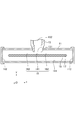
- FIG. 1 is a perspective view showing a heat exchanger of the present embodiment.
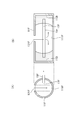
- FIG. 2 is a cross-sectional view showing a II-II cross section of FIG.
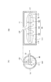
- FIG. 3 is a cross-sectional view showing a III-III cross section of FIG.
- FIG. 4 is a diagram for explaining the diffusion state of the gas-liquid two-phase refrigerant in the comparative example.
- FIG. 5 is a view for explaining the diffusion state of the gas-liquid two-phase refrigerant in the present embodiment.
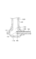
- FIG. 6 is a cross-sectional view showing a heat exchanger according to a modification.
- FIG. 7 is a cross-sectional view showing a heat exchanger according to a modification.
- the heat exchanger 10 As shown in FIG. 1, the heat exchanger 10 according to the present embodiment is used, for example, to cool the battery 20.
- the battery 20 is in a state in which a plurality of batteries stand side by side along the z direction in the drawing.
- the heat exchanger 10 includes tanks 11 and 12 and a tube 15.
- the tube 15 is provided to connect the tank 11 and the tank 12.
- a refrigerant inflow pipe 13 is connected to the tank 11.
- a refrigerant outflow pipe 14 is connected to the tank 12.
- a gas-liquid two-phase refrigerant flows through the refrigerant inflow pipe 13 and flows into the tank 11.
- the gas-liquid two-phase refrigerant flowing into the tank 11 flows through the tube 15.
- the gas-liquid two-phase refrigerant flowing through the tube 15 exchanges heat with the battery 20 to cool the battery 20.
- the refrigerant flowing from the tube 15 into the tank 12 flows out to the refrigerant outflow pipe 14.
- the x-axis is an axis along the longitudinal direction of the tanks 11 and 12.
- the y-axis is a gravity direction, which is a direction in which the refrigerant inflow pipe 13 and the refrigerant outflow pipe 14 extend.
- the z-axis is the direction from the tank 12 to the tank 11, and is the longitudinal direction of the tube 15 and also the stacking direction of the battery 20.
- FIG. 2 is a cross-sectional view showing a II-II cross section of FIG.
- the II-II cross section of FIG. 1 is a yz plane and is a cross section in a plane including the center line of the refrigerant inflow pipe 13.
- the refrigerant inflow pipe 13 is provided with an inflow port 131 and a refrigerant flow path 132.
- the refrigerant inflow pipe 13 is connected to the tank 11 such that the inlet 131 faces the inside of the tank 11.
- the gas-liquid two-phase refrigerant flowing through the refrigerant flow path 132 flows into the tank 11 from the inflow port 131.
- the tube 15 is provided with a refrigerant equalizing portion 16 and an inlet 17.
- the tube 15 is inserted into the tank 11 so that the refrigerant equalizing portion 16 is located inside the tank 11.
- the tube 15 is inserted into the tank 11 so that the refrigerant equalizing portion 16 is located between the inflow port 131 and the opposing wall surface 111 of the tank 11 facing the inflow port 131.
- FIG. 3 is a cross-sectional view showing a III-III cross section of FIG.
- the III-III cross section of FIG. 1 is an xy plane and is a cross section in a plane including the center line of the tank 11.
- the refrigerant equalizing unit 16 includes a refrigerant receiving portion 161 and a refrigerant diffusion portion 162.
- the refrigerant receiving portion 161 is disposed between the inflow port 131 and the opposite wall surface 111 of the tank 11 facing the inflow port 131.
- the refrigerant diffusion portion 162 is provided so as to be connected to both sides of the refrigerant receiving portion 161 in the longitudinal direction (x direction in the drawing) of the tank 11.
- the refrigerant diffusion portion 162 is connected to the refrigerant receiving portion 161 and is provided to extend from the refrigerant receiving portion 161 in the longitudinal direction of the tank 11.
- FIG. 4 shows an example in which the refrigerant equalizing portion 16 is not provided as a comparative example.
- (A) of FIG. 4 is a cross-sectional schematic view corresponding to FIG. 2, and (B) of FIG. 4 is a cross-sectional schematic view corresponding to FIG.
- FIG. 5 is a diagram showing this embodiment.
- (A) of FIG. 5 is a cross-sectional schematic view corresponding to FIG. 2, and (B) of FIG. 5 is a cross-sectional schematic view corresponding to FIG.
- the tube 15F is a tank 11F so that the tip end portion of the tube 15F does not reach between the inflow port 131F and the opposing wall surface 111F. Has been inserted against.
- the gas-liquid two-phase refrigerant flowing into the tank 11F from the inlet 131F is directed to the opposite wall surface 111F immediately below.
- the gas-liquid two-phase refrigerant that has flowed into the tank 11F from the inflow port 131F directly strikes the opposing wall surface 111F and flows toward the side wall surface 112F of the tank 11F.
- the inertia of this flow causes the liquid-phase refrigerant of the gas-liquid two-phase refrigerant to stagnate along the side wall surface 112F. Accordingly, the refrigerant flowing between the inlet 17F and the tube 15F is biased between the gas phase component and the liquid phase component.
- the refrigerant equalizing portion 16 which is the tip portion of the tube 15 reaches between the inflow port 131 and the opposing wall surface 111.
- Tube 15 is inserted into the tank 11.
- at least a part of the gas-liquid two-phase refrigerant flowing from the inflow port 131 into the tank 11F hits the refrigerant receiving portion 161.
- the gas-liquid two-phase refrigerant that has reached the side wall surface 112 flows into the facing wall surface 111 side.
- the gas-liquid two-phase refrigerant flowing in this manner merges with the gas-liquid two-phase refrigerant flowing toward the facing wall surface 111 from the refrigerant diffusion portion 162 via the side wall surface 112 and spreads into the tank 11.
- the heat exchanger 10 is a heat exchanger that exchanges heat with a gas-liquid two-phase refrigerant, and the tubes 15 with which the gas-liquid two-phase refrigerant flows to perform heat exchange
- the tank 11 is connected to one end side, and the gas-liquid two-phase refrigerant flows in from the inflow port 131, and the gas-liquid two-phase refrigerant flowing in flows out to the tube 15.
- a refrigerant receiving portion 161 disposed between the inflow port 131 and the opposing wall surface 111 of the tank 11 facing the inflow port 131 and a refrigerant receiving portion 161 are connected to the refrigerant receiving portion 161.
- a refrigerant equalizing portion 16 is provided which has a refrigerant diffusion portion 162 extending in the longitudinal direction.
- the refrigerant receiving portion 161 is provided between the inflow port 131 where the gas-liquid two-phase refrigerant flows into the tank 11 and the opposing wall surface 111 of the tank 11 facing the inflow port 131, the refrigerant flows from the inflow port 131 The gas-liquid two-phase refrigerant is temporarily received and dispersed by the refrigerant receiving portion 161 without directly facing the opposite wall surface 111. Since the refrigerant diffusion portion 162 is provided in connection with the refrigerant receiving portion 161, a part of the gas-liquid two-phase refrigerant dispersed in the refrigerant receiving portion 161 can be diffused in the longitudinal direction of the tank 11.
- part of the gas-liquid two-phase refrigerant flowing from the inflow port 131 is spread in the longitudinal direction of the tank 11 and then flowed to the opposing wall surface 111 side, while part of the gas-liquid two-phase refrigerant flowing from the inflow port It can be configured to flow in the longitudinal direction after flowing to the opposite wall surface 111 side.
- the tube 15 is provided with a gas-liquid two-phase refrigerant receiving port 17 along the longitudinal direction of the tank 11. Since the gas-liquid two-phase refrigerant flowing into the tank 11 is relatively evenly distributed in the longitudinal direction of the tank 11 by the action of the refrigerant equalizing portion 16, the inlet 17 of the tube 15 is provided along the longitudinal direction of the tank 11 Thus, the gas-liquid two-phase refrigerant can be fed to the tube 15 without large deviation.
- the inflow direction of the gas-liquid two-phase refrigerant into the tank 11 crosses the inflow direction of the gas-liquid two-phase refrigerant into the tube 15. Since the gas-liquid two-phase refrigerant flowing into the tank 11 is relatively evenly distributed in the longitudinal direction of the tank by the action of the refrigerant equalizing portion 16, the flow direction into the tube 15 should be set to intersect the flow direction into the tank 11. Then, the gas-liquid two-phase refrigerant flowing into the tank 11 can be sent out to the tube 15 after being diffused not directly.
- the refrigerant equalizing portion 16 is provided along the longitudinal direction of the tank 11 so as to correspond to the inlet 17 of the tube 15. Since the gas-liquid two-phase refrigerant flowing into the tank 11 distributes relatively uniformly to correspond to the inlet 17 by the action of the refrigerant equalizing portion 16 provided to correspond to the inlet 17 of the tube 15, The liquid two-phase refrigerant can be fed to the tube 15 without a large deviation.
- the refrigerant receiving portion 161 and the refrigerant diffusion portion 162 are connected so as to form the same plane at least in part. Since the gas-liquid two-phase refrigerant flowing from the inflow port 131 is diffused in the refrigerant receiving portion 161 and flows to the refrigerant diffusion portion 162 which forms the same plane at least in part, the gas-liquid two-phase refrigerant is diffused smoothly Uneven flow of the two-phase refrigerant can be suppressed.
- the present invention is not necessarily limited to this aspect.
- a gap may be provided between the refrigerant receiving portion 161 and the refrigerant diffusion portion 162, the refrigerant receiving portion 161 may be provided intermittently, or the refrigerant diffusion portion 162 may be provided intermittently.
- the refrigerant equalizing part 16 including the refrigerant receiving part 161 and the refrigerant diffusing part 162 can adopt various aspects.
- the refrigerant inflow direction to the tank 11 is disposed along the gravity direction.
- the influence of gravity in the diffusion direction can be reduced, and the diffusion effect can be more reliably exhibited.
- the refrigerant equalizing portion 16 is formed by the end of the tube 15. Uneven flow of the gas-liquid two-phase refrigerant can be suppressed with a simple configuration.
- the refrigerant inflow pipe 13A and the tube 15A are inserted into the tank 11A.
- a gas-liquid two-phase refrigerant flowing in the refrigerant flow path 132A flows into the tank 11A from the inflow port 131A.
- the tank 11A is provided with a folded portion along the end of the tube 15A to form the refrigerant equalizing portion 16A.
- the refrigerant equalizing portion 16A is provided so as to protrude to a position where at least a part of the gas-liquid two-phase refrigerant flowing into the tank 11A from the inflow port 131A strikes.
- the refrigerant equalizing portion 16A is provided such that its tip portion extends between the inflow port 131A and the facing wall surface 111A.
- the refrigerant equalizing portion 16A is provided with an inlet 17A for a gas-liquid two-phase refrigerant.
- the gas-liquid two-phase refrigerant flowing out of the receiving port 17A is formed to flow into the tube 15A.
- the refrigerant inflow pipe 13B and the tube 15B are inserted into the tank 11B.
- the gas-liquid two-phase refrigerant flowing in the refrigerant flow path 132B flows into the tank 11B from the inflow port 131B.
- the refrigerant inflow pipe 13B is formed with an insertion end portion 133B which is further expanded in diameter from the inflow port 131B.
- the tube 15B is inserted not at the insertion end portion 133B but at a tip portion thereof between the inflow port 131B and the facing wall surface 111B.
- the gas-liquid two-phase refrigerant flowing in the refrigerant flow path 132B flows from the inflow port 131B toward the opposing wall surface 111B, and does not flow along the insertion end portion 133B larger in diameter than the inflow port 131B. Therefore, the distal end portion of the tube 15B can be used as the refrigerant equalizing portion 16B and the receiving port 17B by inserting the tube 15B so that the distal end portion thereof faces between the inflow port 131B and the facing wall surface 111B.
Landscapes
- Engineering & Computer Science (AREA)
- Physics & Mathematics (AREA)
- Chemical Kinetics & Catalysis (AREA)
- Chemical & Material Sciences (AREA)
- Electrochemistry (AREA)
- General Chemical & Material Sciences (AREA)
- Manufacturing & Machinery (AREA)
- Thermal Sciences (AREA)
- Mechanical Engineering (AREA)
- General Engineering & Computer Science (AREA)
- Fluid Mechanics (AREA)
- Geometry (AREA)
- Details Of Heat-Exchange And Heat-Transfer (AREA)
- Secondary Cells (AREA)
Applications Claiming Priority (2)
| Application Number | Priority Date | Filing Date | Title |
|---|---|---|---|
| JP2017-161087 | 2017-08-24 | ||
| JP2017161087A JP6798453B2 (ja) | 2017-08-24 | 2017-08-24 | 熱交換器 |
Publications (1)
| Publication Number | Publication Date |
|---|---|
| WO2019039327A1 true WO2019039327A1 (ja) | 2019-02-28 |
Family
ID=65438814
Family Applications (1)
| Application Number | Title | Priority Date | Filing Date |
|---|---|---|---|
| PCT/JP2018/030111 Ceased WO2019039327A1 (ja) | 2017-08-24 | 2018-08-10 | 熱交換器 |
Country Status (2)
| Country | Link |
|---|---|
| JP (1) | JP6798453B2 (enExample) |
| WO (1) | WO2019039327A1 (enExample) |
Families Citing this family (1)
| Publication number | Priority date | Publication date | Assignee | Title |
|---|---|---|---|---|
| JP7755497B2 (ja) * | 2022-01-17 | 2025-10-16 | 株式会社日本クライメイトシステムズ | 熱交換器 |
Citations (9)
| Publication number | Priority date | Publication date | Assignee | Title |
|---|---|---|---|---|
| US1484749A (en) * | 1923-04-06 | 1924-02-26 | Fedders Mfg Co Inc | Radiator |
| JPH0359395A (ja) * | 1989-07-28 | 1991-03-14 | Sanden Corp | 2系統熱交換器 |
| JPH10132422A (ja) * | 1996-10-30 | 1998-05-22 | Daikin Ind Ltd | 熱交換器 |
| JP2005030741A (ja) * | 2003-07-11 | 2005-02-03 | Denso Corp | 熱交換器 |
| JP2007218455A (ja) * | 2006-02-14 | 2007-08-30 | Denso Corp | 熱交換器 |
| US20090145591A1 (en) * | 2002-10-29 | 2009-06-11 | Duramax Marine, Llc | Keel cooler with fluid flow diverter |
| JP2011106738A (ja) * | 2009-11-17 | 2011-06-02 | Mitsubishi Electric Corp | 熱交換器およびヒートポンプシステム |
| DE102010032900A1 (de) * | 2010-07-30 | 2012-02-02 | Valeo Klimasysteme Gmbh | Kühlvorrichtung für eine Fahrzeugbatterie mit mehreren Batteriezellengruppen und Fahrzeugbatteriebaugruppe |
| CN103063076A (zh) * | 2012-11-21 | 2013-04-24 | 三花控股集团有限公司 | 换热器 |
-
2017
- 2017-08-24 JP JP2017161087A patent/JP6798453B2/ja not_active Expired - Fee Related
-
2018
- 2018-08-10 WO PCT/JP2018/030111 patent/WO2019039327A1/ja not_active Ceased
Patent Citations (9)
| Publication number | Priority date | Publication date | Assignee | Title |
|---|---|---|---|---|
| US1484749A (en) * | 1923-04-06 | 1924-02-26 | Fedders Mfg Co Inc | Radiator |
| JPH0359395A (ja) * | 1989-07-28 | 1991-03-14 | Sanden Corp | 2系統熱交換器 |
| JPH10132422A (ja) * | 1996-10-30 | 1998-05-22 | Daikin Ind Ltd | 熱交換器 |
| US20090145591A1 (en) * | 2002-10-29 | 2009-06-11 | Duramax Marine, Llc | Keel cooler with fluid flow diverter |
| JP2005030741A (ja) * | 2003-07-11 | 2005-02-03 | Denso Corp | 熱交換器 |
| JP2007218455A (ja) * | 2006-02-14 | 2007-08-30 | Denso Corp | 熱交換器 |
| JP2011106738A (ja) * | 2009-11-17 | 2011-06-02 | Mitsubishi Electric Corp | 熱交換器およびヒートポンプシステム |
| DE102010032900A1 (de) * | 2010-07-30 | 2012-02-02 | Valeo Klimasysteme Gmbh | Kühlvorrichtung für eine Fahrzeugbatterie mit mehreren Batteriezellengruppen und Fahrzeugbatteriebaugruppe |
| CN103063076A (zh) * | 2012-11-21 | 2013-04-24 | 三花控股集团有限公司 | 换热器 |
Also Published As
| Publication number | Publication date |
|---|---|
| JP2019040725A (ja) | 2019-03-14 |
| JP6798453B2 (ja) | 2020-12-09 |
Similar Documents
| Publication | Publication Date | Title |
|---|---|---|
| JPWO2015004719A1 (ja) | 積層型ヘッダー、熱交換器、空気調和装置、及び、積層型ヘッダーの板状体と管とを接合する方法 | |
| JP2006250412A (ja) | 熱交換器 | |
| BRPI1010414A2 (pt) | trocador de calor possuindo desviador de fluxo e método de operação do mesmo | |
| JP5775971B2 (ja) | 空気熱交換器 | |
| JP5147894B2 (ja) | 冷媒分配器、及び、蒸発器 | |
| WO2019039327A1 (ja) | 熱交換器 | |
| EP2982924A1 (en) | Heat exchanger | |
| JP6281909B2 (ja) | パラレルフロー型熱交換器 | |
| JP2015092120A (ja) | 凝縮器 | |
| CN205352172U (zh) | 集流管组件和具有该集流管组件的换热器 | |
| CN104764255A (zh) | 平行流换热器 | |
| JP6079619B2 (ja) | 空調室内機 | |
| KR20120037617A (ko) | 차량용 증발기의 파이프 연결부재 | |
| WO2018055826A1 (ja) | 熱交換器及び冷凍サイクル装置 | |
| US12241699B2 (en) | Heat exchanger | |
| JP2016183847A (ja) | 熱交換器 | |
| JP2016130594A (ja) | 熱交換器の配管構造 | |
| JP2010139085A (ja) | 冷媒分流器 | |
| JP2012063137A (ja) | 冷媒分配器及びヒートポンプ装置 | |
| JP5160792B2 (ja) | 空気調和機の熱交換器 | |
| JP7755497B2 (ja) | 熱交換器 | |
| JP2008232566A (ja) | 熱交換器コネクタ部の形成方法 | |
| JP6172701B2 (ja) | 熱交換器 | |
| JP2015123496A (ja) | 熱交換装置 | |
| CN113710970B (zh) | 热交换器 |
Legal Events
| Date | Code | Title | Description |
|---|---|---|---|
| 121 | Ep: the epo has been informed by wipo that ep was designated in this application |
Ref document number: 18848898 Country of ref document: EP Kind code of ref document: A1 |
|
| NENP | Non-entry into the national phase |
Ref country code: DE |
|
| 122 | Ep: pct application non-entry in european phase |
Ref document number: 18848898 Country of ref document: EP Kind code of ref document: A1 |