WO2019039327A1 - Heat exchanger - Google Patents
Heat exchanger Download PDFInfo
- Publication number
- WO2019039327A1 WO2019039327A1 PCT/JP2018/030111 JP2018030111W WO2019039327A1 WO 2019039327 A1 WO2019039327 A1 WO 2019039327A1 JP 2018030111 W JP2018030111 W JP 2018030111W WO 2019039327 A1 WO2019039327 A1 WO 2019039327A1
- Authority
- WO
- WIPO (PCT)
- Prior art keywords
- refrigerant
- tank
- liquid
- gas
- heat exchanger
- Prior art date
Links
Images


Classifications
-
- F—MECHANICAL ENGINEERING; LIGHTING; HEATING; WEAPONS; BLASTING
- F28—HEAT EXCHANGE IN GENERAL
- F28F—DETAILS OF HEAT-EXCHANGE AND HEAT-TRANSFER APPARATUS, OF GENERAL APPLICATION
- F28F1/00—Tubular elements; Assemblies of tubular elements
- F28F1/02—Tubular elements of cross-section which is non-circular
-
- F—MECHANICAL ENGINEERING; LIGHTING; HEATING; WEAPONS; BLASTING
- F28—HEAT EXCHANGE IN GENERAL
- F28F—DETAILS OF HEAT-EXCHANGE AND HEAT-TRANSFER APPARATUS, OF GENERAL APPLICATION
- F28F9/00—Casings; Header boxes; Auxiliary supports for elements; Auxiliary members within casings
- F28F9/02—Header boxes; End plates
-
- F—MECHANICAL ENGINEERING; LIGHTING; HEATING; WEAPONS; BLASTING
- F28—HEAT EXCHANGE IN GENERAL
- F28F—DETAILS OF HEAT-EXCHANGE AND HEAT-TRANSFER APPARATUS, OF GENERAL APPLICATION
- F28F9/00—Casings; Header boxes; Auxiliary supports for elements; Auxiliary members within casings
- F28F9/24—Arrangements for promoting turbulent flow of heat-exchange media, e.g. by plates
-
- H—ELECTRICITY
- H01—ELECTRIC ELEMENTS
- H01M—PROCESSES OR MEANS, e.g. BATTERIES, FOR THE DIRECT CONVERSION OF CHEMICAL ENERGY INTO ELECTRICAL ENERGY
- H01M10/00—Secondary cells; Manufacture thereof
- H01M10/60—Heating or cooling; Temperature control
- H01M10/61—Types of temperature control
- H01M10/613—Cooling or keeping cold
-
- H—ELECTRICITY
- H01—ELECTRIC ELEMENTS
- H01M—PROCESSES OR MEANS, e.g. BATTERIES, FOR THE DIRECT CONVERSION OF CHEMICAL ENERGY INTO ELECTRICAL ENERGY
- H01M10/00—Secondary cells; Manufacture thereof
- H01M10/60—Heating or cooling; Temperature control
- H01M10/65—Means for temperature control structurally associated with the cells
- H01M10/655—Solid structures for heat exchange or heat conduction
- H01M10/6556—Solid parts with flow channel passages or pipes for heat exchange
-
- H—ELECTRICITY
- H01—ELECTRIC ELEMENTS
- H01M—PROCESSES OR MEANS, e.g. BATTERIES, FOR THE DIRECT CONVERSION OF CHEMICAL ENERGY INTO ELECTRICAL ENERGY
- H01M10/00—Secondary cells; Manufacture thereof
- H01M10/60—Heating or cooling; Temperature control
- H01M10/65—Means for temperature control structurally associated with the cells
- H01M10/656—Means for temperature control structurally associated with the cells characterised by the type of heat-exchange fluid
- H01M10/6569—Fluids undergoing a liquid-gas phase change or transition, e.g. evaporation or condensation
-
- Y—GENERAL TAGGING OF NEW TECHNOLOGICAL DEVELOPMENTS; GENERAL TAGGING OF CROSS-SECTIONAL TECHNOLOGIES SPANNING OVER SEVERAL SECTIONS OF THE IPC; TECHNICAL SUBJECTS COVERED BY FORMER USPC CROSS-REFERENCE ART COLLECTIONS [XRACs] AND DIGESTS
- Y02—TECHNOLOGIES OR APPLICATIONS FOR MITIGATION OR ADAPTATION AGAINST CLIMATE CHANGE
- Y02E—REDUCTION OF GREENHOUSE GAS [GHG] EMISSIONS, RELATED TO ENERGY GENERATION, TRANSMISSION OR DISTRIBUTION
- Y02E60/00—Enabling technologies; Technologies with a potential or indirect contribution to GHG emissions mitigation
- Y02E60/10—Energy storage using batteries
Definitions
- the present disclosure relates to a heat exchanger that exchanges heat from a gas-liquid two-phase refrigerant.
- refrigerant flow channels are provided that are arranged in a flat direction in a flat tube.
- the tube is connected to a longitudinally extending tank.
- the flat direction of the tube and the longitudinal direction of the tank are arranged along each other.
- a refrigerant pipe is provided to the tank so that the refrigerant flows in a direction substantially orthogonal to the longitudinal direction of the tank.
- Patent Document 1 when a gas-liquid two-phase refrigerant flows as the refrigerant, the liquid refrigerant is biased to both ends in the longitudinal direction of the tank, and the ratio of the liquid refrigerant in the gas-liquid two-phase refrigerant is biased between the tank center and both ends Can happen. When this phenomenon occurs, the refrigerant flowing into the tube also becomes nonuniform, which may affect the heat exchange performance.
- the present disclosure aims to provide a heat exchanger capable of suppressing the nonuniform flow of the gas-liquid two-phase refrigerant even when the gas-liquid two-phase refrigerant flows and ensuring the heat exchange performance. I assume.
- the present disclosure is a heat exchanger that exchanges heat between a gas-liquid two-phase refrigerant, and is connected to a tube (15) that the gas-liquid two-phase refrigerant flows in for heat exchange, and one end of the tube 131) a gas-liquid two-phase refrigerant flowing in, and a tank (11) configured to flow the gas-liquid two-phase refrigerant flowing out into the tube;
- a refrigerant equalizing portion (16) having a refrigerant receiving portion (161) disposed between the wall surface and a refrigerant diffusing portion (162) connected to the refrigerant receiving portion and extending in the longitudinal direction of the tank from the refrigerant receiving portion It is provided inside.
- the refrigerant receiving portion is provided between the inlet where the gas-liquid two-phase refrigerant flows into the tank and the opposing wall surface of the tank facing the inlet, the gas-liquid two-phase refrigerant flowing from the inlet is directly
- the refrigerant receiving portion temporarily receives and disperses without moving to the opposite wall surface. Since the refrigerant diffusion portion is connected to the refrigerant receiving portion, a part of the gas-liquid two-phase refrigerant dispersed in the refrigerant receiving portion can be diffused in the longitudinal direction of the tank.
- gas-liquid two-phase refrigerant flowing in from the inflow port is spread in the longitudinal direction of the tank and then flowed to the opposing wall surface side
- a part of the gas-liquid two-phase refrigerant flowing in from the inflow port After flowing it can be configured to flow in the longitudinal direction.
- the gas-liquid two-phase refrigerant flowing to the opposite wall surface side after first spreading in the longitudinal direction and the gas-liquid two-phase refrigerant spreading first in the opposite wall surface side and then extending in the longitudinal direction merge and spread in the tank. Since the gas-liquid two-phase refrigerant is relatively uniformly present in the longitudinal direction, it is possible to suppress the non-uniform flow of the gas-liquid two-phase refrigerant.
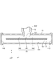
- FIG. 1 is a perspective view showing a heat exchanger of the present embodiment.
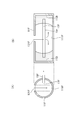
- FIG. 2 is a cross-sectional view showing a II-II cross section of FIG.
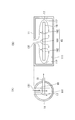
- FIG. 3 is a cross-sectional view showing a III-III cross section of FIG.
- FIG. 4 is a diagram for explaining the diffusion state of the gas-liquid two-phase refrigerant in the comparative example.
- FIG. 5 is a view for explaining the diffusion state of the gas-liquid two-phase refrigerant in the present embodiment.
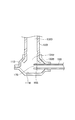
- FIG. 6 is a cross-sectional view showing a heat exchanger according to a modification.
- FIG. 7 is a cross-sectional view showing a heat exchanger according to a modification.
- the heat exchanger 10 As shown in FIG. 1, the heat exchanger 10 according to the present embodiment is used, for example, to cool the battery 20.
- the battery 20 is in a state in which a plurality of batteries stand side by side along the z direction in the drawing.
- the heat exchanger 10 includes tanks 11 and 12 and a tube 15.
- the tube 15 is provided to connect the tank 11 and the tank 12.
- a refrigerant inflow pipe 13 is connected to the tank 11.
- a refrigerant outflow pipe 14 is connected to the tank 12.
- a gas-liquid two-phase refrigerant flows through the refrigerant inflow pipe 13 and flows into the tank 11.
- the gas-liquid two-phase refrigerant flowing into the tank 11 flows through the tube 15.
- the gas-liquid two-phase refrigerant flowing through the tube 15 exchanges heat with the battery 20 to cool the battery 20.
- the refrigerant flowing from the tube 15 into the tank 12 flows out to the refrigerant outflow pipe 14.
- the x-axis is an axis along the longitudinal direction of the tanks 11 and 12.
- the y-axis is a gravity direction, which is a direction in which the refrigerant inflow pipe 13 and the refrigerant outflow pipe 14 extend.
- the z-axis is the direction from the tank 12 to the tank 11, and is the longitudinal direction of the tube 15 and also the stacking direction of the battery 20.
- FIG. 2 is a cross-sectional view showing a II-II cross section of FIG.
- the II-II cross section of FIG. 1 is a yz plane and is a cross section in a plane including the center line of the refrigerant inflow pipe 13.
- the refrigerant inflow pipe 13 is provided with an inflow port 131 and a refrigerant flow path 132.
- the refrigerant inflow pipe 13 is connected to the tank 11 such that the inlet 131 faces the inside of the tank 11.
- the gas-liquid two-phase refrigerant flowing through the refrigerant flow path 132 flows into the tank 11 from the inflow port 131.
- the tube 15 is provided with a refrigerant equalizing portion 16 and an inlet 17.
- the tube 15 is inserted into the tank 11 so that the refrigerant equalizing portion 16 is located inside the tank 11.
- the tube 15 is inserted into the tank 11 so that the refrigerant equalizing portion 16 is located between the inflow port 131 and the opposing wall surface 111 of the tank 11 facing the inflow port 131.
- FIG. 3 is a cross-sectional view showing a III-III cross section of FIG.
- the III-III cross section of FIG. 1 is an xy plane and is a cross section in a plane including the center line of the tank 11.
- the refrigerant equalizing unit 16 includes a refrigerant receiving portion 161 and a refrigerant diffusion portion 162.
- the refrigerant receiving portion 161 is disposed between the inflow port 131 and the opposite wall surface 111 of the tank 11 facing the inflow port 131.
- the refrigerant diffusion portion 162 is provided so as to be connected to both sides of the refrigerant receiving portion 161 in the longitudinal direction (x direction in the drawing) of the tank 11.
- the refrigerant diffusion portion 162 is connected to the refrigerant receiving portion 161 and is provided to extend from the refrigerant receiving portion 161 in the longitudinal direction of the tank 11.
- FIG. 4 shows an example in which the refrigerant equalizing portion 16 is not provided as a comparative example.
- (A) of FIG. 4 is a cross-sectional schematic view corresponding to FIG. 2, and (B) of FIG. 4 is a cross-sectional schematic view corresponding to FIG.
- FIG. 5 is a diagram showing this embodiment.
- (A) of FIG. 5 is a cross-sectional schematic view corresponding to FIG. 2, and (B) of FIG. 5 is a cross-sectional schematic view corresponding to FIG.
- the tube 15F is a tank 11F so that the tip end portion of the tube 15F does not reach between the inflow port 131F and the opposing wall surface 111F. Has been inserted against.
- the gas-liquid two-phase refrigerant flowing into the tank 11F from the inlet 131F is directed to the opposite wall surface 111F immediately below.
- the gas-liquid two-phase refrigerant that has flowed into the tank 11F from the inflow port 131F directly strikes the opposing wall surface 111F and flows toward the side wall surface 112F of the tank 11F.
- the inertia of this flow causes the liquid-phase refrigerant of the gas-liquid two-phase refrigerant to stagnate along the side wall surface 112F. Accordingly, the refrigerant flowing between the inlet 17F and the tube 15F is biased between the gas phase component and the liquid phase component.
- the refrigerant equalizing portion 16 which is the tip portion of the tube 15 reaches between the inflow port 131 and the opposing wall surface 111.
- Tube 15 is inserted into the tank 11.
- at least a part of the gas-liquid two-phase refrigerant flowing from the inflow port 131 into the tank 11F hits the refrigerant receiving portion 161.
- the gas-liquid two-phase refrigerant that has reached the side wall surface 112 flows into the facing wall surface 111 side.
- the gas-liquid two-phase refrigerant flowing in this manner merges with the gas-liquid two-phase refrigerant flowing toward the facing wall surface 111 from the refrigerant diffusion portion 162 via the side wall surface 112 and spreads into the tank 11.
- the heat exchanger 10 is a heat exchanger that exchanges heat with a gas-liquid two-phase refrigerant, and the tubes 15 with which the gas-liquid two-phase refrigerant flows to perform heat exchange
- the tank 11 is connected to one end side, and the gas-liquid two-phase refrigerant flows in from the inflow port 131, and the gas-liquid two-phase refrigerant flowing in flows out to the tube 15.
- a refrigerant receiving portion 161 disposed between the inflow port 131 and the opposing wall surface 111 of the tank 11 facing the inflow port 131 and a refrigerant receiving portion 161 are connected to the refrigerant receiving portion 161.
- a refrigerant equalizing portion 16 is provided which has a refrigerant diffusion portion 162 extending in the longitudinal direction.
- the refrigerant receiving portion 161 is provided between the inflow port 131 where the gas-liquid two-phase refrigerant flows into the tank 11 and the opposing wall surface 111 of the tank 11 facing the inflow port 131, the refrigerant flows from the inflow port 131 The gas-liquid two-phase refrigerant is temporarily received and dispersed by the refrigerant receiving portion 161 without directly facing the opposite wall surface 111. Since the refrigerant diffusion portion 162 is provided in connection with the refrigerant receiving portion 161, a part of the gas-liquid two-phase refrigerant dispersed in the refrigerant receiving portion 161 can be diffused in the longitudinal direction of the tank 11.
- part of the gas-liquid two-phase refrigerant flowing from the inflow port 131 is spread in the longitudinal direction of the tank 11 and then flowed to the opposing wall surface 111 side, while part of the gas-liquid two-phase refrigerant flowing from the inflow port It can be configured to flow in the longitudinal direction after flowing to the opposite wall surface 111 side.
- the tube 15 is provided with a gas-liquid two-phase refrigerant receiving port 17 along the longitudinal direction of the tank 11. Since the gas-liquid two-phase refrigerant flowing into the tank 11 is relatively evenly distributed in the longitudinal direction of the tank 11 by the action of the refrigerant equalizing portion 16, the inlet 17 of the tube 15 is provided along the longitudinal direction of the tank 11 Thus, the gas-liquid two-phase refrigerant can be fed to the tube 15 without large deviation.
- the inflow direction of the gas-liquid two-phase refrigerant into the tank 11 crosses the inflow direction of the gas-liquid two-phase refrigerant into the tube 15. Since the gas-liquid two-phase refrigerant flowing into the tank 11 is relatively evenly distributed in the longitudinal direction of the tank by the action of the refrigerant equalizing portion 16, the flow direction into the tube 15 should be set to intersect the flow direction into the tank 11. Then, the gas-liquid two-phase refrigerant flowing into the tank 11 can be sent out to the tube 15 after being diffused not directly.
- the refrigerant equalizing portion 16 is provided along the longitudinal direction of the tank 11 so as to correspond to the inlet 17 of the tube 15. Since the gas-liquid two-phase refrigerant flowing into the tank 11 distributes relatively uniformly to correspond to the inlet 17 by the action of the refrigerant equalizing portion 16 provided to correspond to the inlet 17 of the tube 15, The liquid two-phase refrigerant can be fed to the tube 15 without a large deviation.
- the refrigerant receiving portion 161 and the refrigerant diffusion portion 162 are connected so as to form the same plane at least in part. Since the gas-liquid two-phase refrigerant flowing from the inflow port 131 is diffused in the refrigerant receiving portion 161 and flows to the refrigerant diffusion portion 162 which forms the same plane at least in part, the gas-liquid two-phase refrigerant is diffused smoothly Uneven flow of the two-phase refrigerant can be suppressed.
- the present invention is not necessarily limited to this aspect.
- a gap may be provided between the refrigerant receiving portion 161 and the refrigerant diffusion portion 162, the refrigerant receiving portion 161 may be provided intermittently, or the refrigerant diffusion portion 162 may be provided intermittently.
- the refrigerant equalizing part 16 including the refrigerant receiving part 161 and the refrigerant diffusing part 162 can adopt various aspects.
- the refrigerant inflow direction to the tank 11 is disposed along the gravity direction.
- the influence of gravity in the diffusion direction can be reduced, and the diffusion effect can be more reliably exhibited.
- the refrigerant equalizing portion 16 is formed by the end of the tube 15. Uneven flow of the gas-liquid two-phase refrigerant can be suppressed with a simple configuration.
- the refrigerant inflow pipe 13A and the tube 15A are inserted into the tank 11A.
- a gas-liquid two-phase refrigerant flowing in the refrigerant flow path 132A flows into the tank 11A from the inflow port 131A.
- the tank 11A is provided with a folded portion along the end of the tube 15A to form the refrigerant equalizing portion 16A.
- the refrigerant equalizing portion 16A is provided so as to protrude to a position where at least a part of the gas-liquid two-phase refrigerant flowing into the tank 11A from the inflow port 131A strikes.
- the refrigerant equalizing portion 16A is provided such that its tip portion extends between the inflow port 131A and the facing wall surface 111A.
- the refrigerant equalizing portion 16A is provided with an inlet 17A for a gas-liquid two-phase refrigerant.
- the gas-liquid two-phase refrigerant flowing out of the receiving port 17A is formed to flow into the tube 15A.
- the refrigerant inflow pipe 13B and the tube 15B are inserted into the tank 11B.
- the gas-liquid two-phase refrigerant flowing in the refrigerant flow path 132B flows into the tank 11B from the inflow port 131B.
- the refrigerant inflow pipe 13B is formed with an insertion end portion 133B which is further expanded in diameter from the inflow port 131B.
- the tube 15B is inserted not at the insertion end portion 133B but at a tip portion thereof between the inflow port 131B and the facing wall surface 111B.
- the gas-liquid two-phase refrigerant flowing in the refrigerant flow path 132B flows from the inflow port 131B toward the opposing wall surface 111B, and does not flow along the insertion end portion 133B larger in diameter than the inflow port 131B. Therefore, the distal end portion of the tube 15B can be used as the refrigerant equalizing portion 16B and the receiving port 17B by inserting the tube 15B so that the distal end portion thereof faces between the inflow port 131B and the facing wall surface 111B.
Abstract
This heat exchanger is provided with a tube (15) into which a gas-liquid two-phase refrigerant flows and in which heat is exchanged, and a tank (11) which is linked to one end side of the tube (15) and is configured so that the gas-liquid two-phase refrigerant flows in from an inflow port (131), and the gas-liquid two-phase refrigerant that has flowed in flows out into the tube. A refrigerant equalization section (16) is provided inside the tank (11) and comprises a refrigerant receiving section (161) and refrigerant diffusion sections (162), the refrigerant receiving section being arranged between the inflow port (131) and an opposing wall surface (111) of the tank (11) opposite to the inflow port, and the refrigerant diffusion sections being linked to the refrigerant receiving section (161) and extending in the longitudinal direction of the tank (11) from the refrigerant receiving section (161).
Description
本出願は、2017年8月24日に出願された日本国特許出願2017-161087号に基づくものであって、その優先権の利益を主張するものであり、その特許出願の全ての内容が、参照により本明細書に組み込まれる。
This application is based on Japanese Patent Application No. 2017-161087 filed on Aug. 24, 2017 and claims the benefit of its priority, and the entire contents of that patent application are: Incorporated herein by reference.
本開示は、気液二相冷媒を熱交換する熱交換器に関する。
The present disclosure relates to a heat exchanger that exchanges heat from a gas-liquid two-phase refrigerant.
下記特許文献1に記載の熱交換器は、扁平形状のチューブに扁平方向に並んだ冷媒流路が設けられている。チューブは、長手方向に延びているタンクに接続されている。チューブの扁平方向とタンクの長手方向とは、互いに沿うように配置されている。タンクに対しては、タンクの長手方向に略直交する方向から冷媒が流入するように冷媒管が設けられている。
In the heat exchanger described in Patent Document 1 below, refrigerant flow channels are provided that are arranged in a flat direction in a flat tube. The tube is connected to a longitudinally extending tank. The flat direction of the tube and the longitudinal direction of the tank are arranged along each other. A refrigerant pipe is provided to the tank so that the refrigerant flows in a direction substantially orthogonal to the longitudinal direction of the tank.
特許文献1では、冷媒として気液二相冷媒を流した場合、タンクの長手方向両端に液冷媒が偏ってしまい、タンク中央側と両端とで気液二相冷媒における液冷媒の比率が偏る現象が起こる可能性がある。この現象が発生すると、チューブに流れ込む冷媒も不均一なものとなり、熱交換性能に影響を与えるおそれがある。
In Patent Document 1, when a gas-liquid two-phase refrigerant flows as the refrigerant, the liquid refrigerant is biased to both ends in the longitudinal direction of the tank, and the ratio of the liquid refrigerant in the gas-liquid two-phase refrigerant is biased between the tank center and both ends Can happen. When this phenomenon occurs, the refrigerant flowing into the tube also becomes nonuniform, which may affect the heat exchange performance.
本開示は、気液二相冷媒を流した場合であっても、気液二相冷媒の不均一な流れを抑制することができ、熱交換性能を確保できる熱交換器を提供することを目的とする。
The present disclosure aims to provide a heat exchanger capable of suppressing the nonuniform flow of the gas-liquid two-phase refrigerant even when the gas-liquid two-phase refrigerant flows and ensuring the heat exchange performance. I assume.
本開示は、気液二相冷媒を熱交換する熱交換器であって、気液二相冷媒が流入し熱交換を行うチューブ(15)と、チューブの一端側に繋がっており、流入口(131)から気液二相冷媒が流入し、流入した気液二相冷媒がチューブに流出するように構成されているタンク(11)と、を備え、流入口と流入口に対向するタンクの対向壁面との間に配置される冷媒受け部分(161)、及び冷媒受け部分に繋がっており冷媒受け部分からタンクの長手方向に延びる冷媒拡散部分(162)、を有する冷媒均等部(16)がタンク内に設けられている。
The present disclosure is a heat exchanger that exchanges heat between a gas-liquid two-phase refrigerant, and is connected to a tube (15) that the gas-liquid two-phase refrigerant flows in for heat exchange, and one end of the tube 131) a gas-liquid two-phase refrigerant flowing in, and a tank (11) configured to flow the gas-liquid two-phase refrigerant flowing out into the tube; A refrigerant equalizing portion (16) having a refrigerant receiving portion (161) disposed between the wall surface and a refrigerant diffusing portion (162) connected to the refrigerant receiving portion and extending in the longitudinal direction of the tank from the refrigerant receiving portion It is provided inside.
タンクに気液二相冷媒が流入する流入口と、その流入口に対向するタンクの対向壁面との間に冷媒受け部分が設けられているので、流入口から流入した気液二相冷媒が直接対向壁面に向かわずに一旦冷媒受け部分で受け止められ分散する。冷媒受け部分に繋げて冷媒拡散部分が設けられているので、冷媒受け部分で分散された気液二相冷媒の一部をタンクの長手方向に拡散することができる。従って、流入口から流入した気液二相冷媒の一部をタンクの長手方向に広げてから対向壁面側に流す一方で、流入口から流入した気液二相冷媒の一部を対向壁面側に流してから長手方向に流すように構成することができる。先に長手方向に広げてから対向壁面側に流れる気液二相冷媒と、先に対向壁面側に流れてから長手方向に広がる気液二相冷媒とが合流してタンク内に行き渡り、タンクの長手方向において気液二相冷媒が比較的均等に存在することになって、気液二相冷媒の不均一な流れを抑制することができる。
Since the refrigerant receiving portion is provided between the inlet where the gas-liquid two-phase refrigerant flows into the tank and the opposing wall surface of the tank facing the inlet, the gas-liquid two-phase refrigerant flowing from the inlet is directly The refrigerant receiving portion temporarily receives and disperses without moving to the opposite wall surface. Since the refrigerant diffusion portion is connected to the refrigerant receiving portion, a part of the gas-liquid two-phase refrigerant dispersed in the refrigerant receiving portion can be diffused in the longitudinal direction of the tank. Therefore, while a part of the gas-liquid two-phase refrigerant flowing in from the inflow port is spread in the longitudinal direction of the tank and then flowed to the opposing wall surface side, a part of the gas-liquid two-phase refrigerant flowing in from the inflow port After flowing, it can be configured to flow in the longitudinal direction. The gas-liquid two-phase refrigerant flowing to the opposite wall surface side after first spreading in the longitudinal direction and the gas-liquid two-phase refrigerant spreading first in the opposite wall surface side and then extending in the longitudinal direction merge and spread in the tank. Since the gas-liquid two-phase refrigerant is relatively uniformly present in the longitudinal direction, it is possible to suppress the non-uniform flow of the gas-liquid two-phase refrigerant.
尚、「発明の概要」及び「請求の範囲」に記載した括弧内の符号は、後述する「発明を実施するための形態」との対応関係を示すものであって、「発明の概要」及び「請求の範囲」が、後述する「発明を実施するための形態」に限定されることを示すものではない。
The reference numerals in parentheses described in the “Summary of the invention” and the “claims” indicate the correspondence with the “embodiments for carrying out the invention” described later, and the “Summary of the Invention” and The scope of the claims does not indicate that the scope of the present invention is limited to the embodiments described below.
以下、添付図面を参照しながら本実施形態について説明する。説明の理解を容易にするため、各図面において同一の構成要素に対しては可能な限り同一の符号を付して、重複する説明は省略する。
Hereinafter, the present embodiment will be described with reference to the attached drawings. In order to facilitate understanding of the description, the same constituent elements in the drawings are denoted by the same reference numerals as much as possible, and redundant description will be omitted.
図1に示されるように、本実施形態に係る熱交換器10は、例えば、電池20を冷却するために用いられる。電池20は、図中z方向に沿って複数の電池が並立した状態となっている。
As shown in FIG. 1, the heat exchanger 10 according to the present embodiment is used, for example, to cool the battery 20. The battery 20 is in a state in which a plurality of batteries stand side by side along the z direction in the drawing.
熱交換器10は、タンク11,12と、チューブ15と、を備えている。チューブ15は、タンク11とタンク12とを繋ぐように設けられている。タンク11には、冷媒流入管13が繋がれている。タンク12には、冷媒流出管14が繋がれている。
The heat exchanger 10 includes tanks 11 and 12 and a tube 15. The tube 15 is provided to connect the tank 11 and the tank 12. A refrigerant inflow pipe 13 is connected to the tank 11. A refrigerant outflow pipe 14 is connected to the tank 12.
冷媒流入管13には、気液二相冷媒が流れており、タンク11に流入する。タンク11に流入した気液二相冷媒は、チューブ15を流れる。チューブ15を流れる気液二相冷媒は、電池20と熱交換を行い、電池20を冷却する。チューブ15からタンク12に流れ込んだ冷媒は、冷媒流出管14に流れ出る。
A gas-liquid two-phase refrigerant flows through the refrigerant inflow pipe 13 and flows into the tank 11. The gas-liquid two-phase refrigerant flowing into the tank 11 flows through the tube 15. The gas-liquid two-phase refrigerant flowing through the tube 15 exchanges heat with the battery 20 to cool the battery 20. The refrigerant flowing from the tube 15 into the tank 12 flows out to the refrigerant outflow pipe 14.
尚、図1においては、xyzの座標軸を設定している。x軸は、タンク11,12の長手方向に沿った軸である。y軸は、重力方向であって、冷媒流入管13及び冷媒流出管14が延びている方向である。z軸は、タンク12からタンク11に向かう方向であり、チューブ15の長手方向であって、電池20の積層方向でもある。
In FIG. 1, coordinate axes of x, y, and z are set. The x-axis is an axis along the longitudinal direction of the tanks 11 and 12. The y-axis is a gravity direction, which is a direction in which the refrigerant inflow pipe 13 and the refrigerant outflow pipe 14 extend. The z-axis is the direction from the tank 12 to the tank 11, and is the longitudinal direction of the tube 15 and also the stacking direction of the battery 20.
続いて、図2を参照しながら説明を続ける。図2は、図1のII-II断面を示す断面図である。図1のII-II断面は、yz平面であって、冷媒流入管13の中心線を含む平面での断面である。
Subsequently, the description will be continued with reference to FIG. FIG. 2 is a cross-sectional view showing a II-II cross section of FIG. The II-II cross section of FIG. 1 is a yz plane and is a cross section in a plane including the center line of the refrigerant inflow pipe 13.
冷媒流入管13は、流入口131と、冷媒流路132とが設けられている。冷媒流入管13は、流入口131がタンク11内に臨むように、タンク11に対して繋がれている。冷媒流路132を流れる気液二相冷媒は、流入口131からタンク11内へと流れ込む。
The refrigerant inflow pipe 13 is provided with an inflow port 131 and a refrigerant flow path 132. The refrigerant inflow pipe 13 is connected to the tank 11 such that the inlet 131 faces the inside of the tank 11. The gas-liquid two-phase refrigerant flowing through the refrigerant flow path 132 flows into the tank 11 from the inflow port 131.
チューブ15は、冷媒均等部16と、受入口17とが設けられている。チューブ15は、冷媒均等部16がタンク11の内部に位置するように、タンク11に対して挿入されている。冷媒均等部16が、流入口131と、流入口131に対向するタンク11の対向壁面111との間に位置するように、チューブ15はタンク11に挿入されている。
The tube 15 is provided with a refrigerant equalizing portion 16 and an inlet 17. The tube 15 is inserted into the tank 11 so that the refrigerant equalizing portion 16 is located inside the tank 11. The tube 15 is inserted into the tank 11 so that the refrigerant equalizing portion 16 is located between the inflow port 131 and the opposing wall surface 111 of the tank 11 facing the inflow port 131.
続いて、図3を参照しながら説明を続ける。図3は、図1のIII-III断面を示す断面図である。図1のIII-III断面は、xy平面であって、タンク11の中心線を含む平面での断面である。
Subsequently, the description will be continued with reference to FIG. FIG. 3 is a cross-sectional view showing a III-III cross section of FIG. The III-III cross section of FIG. 1 is an xy plane and is a cross section in a plane including the center line of the tank 11.
冷媒均等部16は、冷媒受け部分161と、冷媒拡散部分162とを備えている。冷媒受け部分161は、流入口131と流入口131に対向するタンク11の対向壁面111との間に配置されている。冷媒拡散部分162は、タンク11の長手方向(図中x方向)において冷媒受け部分161の両側に繋がるように設けられている。冷媒拡散部分162は、冷媒受け部分161に繋がっており冷媒受け部分161からタンク11の長手方向に延びるように設けられている。
The refrigerant equalizing unit 16 includes a refrigerant receiving portion 161 and a refrigerant diffusion portion 162. The refrigerant receiving portion 161 is disposed between the inflow port 131 and the opposite wall surface 111 of the tank 11 facing the inflow port 131. The refrigerant diffusion portion 162 is provided so as to be connected to both sides of the refrigerant receiving portion 161 in the longitudinal direction (x direction in the drawing) of the tank 11. The refrigerant diffusion portion 162 is connected to the refrigerant receiving portion 161 and is provided to extend from the refrigerant receiving portion 161 in the longitudinal direction of the tank 11.
冷媒均等部16の作用及び効果について、図4及び図5を参照しながら説明する。図4は、比較例として冷媒均等部16を設けていない例を示している。図4の(A)は、図2に対応する断面模式図であり、図4の(B)は、図3に対応する断面模式図である。図5は、本実施形態を示す図である。図5の(A)は、図2に対応する断面模式図であり、図5の(B)は、図3に対応する断面模式図である。
The operation and effects of the refrigerant equalizing portion 16 will be described with reference to FIGS. 4 and 5. FIG. 4 shows an example in which the refrigerant equalizing portion 16 is not provided as a comparative example. (A) of FIG. 4 is a cross-sectional schematic view corresponding to FIG. 2, and (B) of FIG. 4 is a cross-sectional schematic view corresponding to FIG. FIG. 5 is a diagram showing this embodiment. (A) of FIG. 5 is a cross-sectional schematic view corresponding to FIG. 2, and (B) of FIG. 5 is a cross-sectional schematic view corresponding to FIG.
図4の(A)に示されるように、冷媒均等部16を設けていない場合、チューブ15Fの先端部分が、流入口131Fと対向壁面111Fとの間に到達しないように、チューブ15Fがタンク11Fに対して挿入されている。流入口131Fからタンク11Fに流入する気液二相冷媒は、直下の対向壁面111Fに向かう。
As shown in FIG. 4A, when the refrigerant equalizing portion 16 is not provided, the tube 15F is a tank 11F so that the tip end portion of the tube 15F does not reach between the inflow port 131F and the opposing wall surface 111F. Has been inserted against. The gas-liquid two-phase refrigerant flowing into the tank 11F from the inlet 131F is directed to the opposite wall surface 111F immediately below.
図4の(B)に示されるように、流入口131Fからタンク11F内に流入した気液二相冷媒は、対向壁面111Fに直接当たり、タンク11Fの側壁面112Fに向かって流れる。この流れの慣性によって、気液二相冷媒の液相冷媒が側壁面112Fに沿って滞留する。従って、受入口17Fからチューブ15F内に流れる冷媒に気相成分と液相成分との偏りが発生することになる。
As shown in FIG. 4B, the gas-liquid two-phase refrigerant that has flowed into the tank 11F from the inflow port 131F directly strikes the opposing wall surface 111F and flows toward the side wall surface 112F of the tank 11F. The inertia of this flow causes the liquid-phase refrigerant of the gas-liquid two-phase refrigerant to stagnate along the side wall surface 112F. Accordingly, the refrigerant flowing between the inlet 17F and the tube 15F is biased between the gas phase component and the liquid phase component.
図5の(A)に示されるように、冷媒均等部16を設けている場合、チューブ15の先端部分である冷媒均等部16が、流入口131と対向壁面111との間に到達するように、チューブ15がタンク11に対して挿入されている。図5の(A)及び(B)に示されるように、流入口131からタンク11Fに流入する気液二相冷媒は、少なくともその一部が冷媒受け部分161に当たる。
As shown in FIG. 5A, when the refrigerant equalizing portion 16 is provided, the refrigerant equalizing portion 16 which is the tip portion of the tube 15 reaches between the inflow port 131 and the opposing wall surface 111. , Tube 15 is inserted into the tank 11. As shown in (A) and (B) of FIG. 5, at least a part of the gas-liquid two-phase refrigerant flowing from the inflow port 131 into the tank 11F hits the refrigerant receiving portion 161.
冷媒受け部分161に当たった気液二相冷媒は、一部が冷媒拡散部分162に沿って流れ、一部はチューブ15の先端側を経由して対向壁面111に向かって流れる。冷媒拡散部分162に沿って流れる気液二相冷媒は、タンク11の側壁面112に向かって流れる。側壁面112に到達した気液二相冷媒は、対向壁面111側に流れ込む。
A part of the gas-liquid two-phase refrigerant that has collided with the refrigerant receiving portion 161 flows along the refrigerant diffusion portion 162 and a portion flows toward the opposing wall surface 111 via the tip end of the tube 15. The gas-liquid two-phase refrigerant flowing along the refrigerant diffusion portion 162 flows toward the side wall surface 112 of the tank 11. The gas-liquid two-phase refrigerant that has reached the side wall surface 112 flows into the facing wall surface 111 side.
流入口131からチューブ15の先端側を経由して対向壁面111に向かって流れた気液二相冷媒は、タンク11の側壁面112に向かって流れる。このように流れる気液二相冷媒は、冷媒拡散部分162から側壁面112を経由して対向壁面111に向かって流れる気液二相冷媒と合流してタンク11内に行き渡る。
The gas-liquid two-phase refrigerant that has flowed from the inflow port 131 toward the opposing wall surface 111 via the distal end side of the tube 15 flows toward the side wall surface 112 of the tank 11. The gas-liquid two-phase refrigerant flowing in this manner merges with the gas-liquid two-phase refrigerant flowing toward the facing wall surface 111 from the refrigerant diffusion portion 162 via the side wall surface 112 and spreads into the tank 11.
上記したように本実施形態に係る熱交換器10は、気液二相冷媒を熱交換する熱交換器であって、気液二相冷媒が流入し熱交換を行うチューブ15と、チューブ15の一端側に繋がっており、流入口131から気液二相冷媒が流入し、流入した気液二相冷媒がチューブ15に流出するように構成されているタンク11と、を備えている。タンク11内には、流入口131と流入口131に対向するタンク11の対向壁面111との間に配置される冷媒受け部分161、及び冷媒受け部分161に繋がっており冷媒受け部分161からタンク11の長手方向に延びる冷媒拡散部分162、を有する冷媒均等部16が設けられている。
As described above, the heat exchanger 10 according to the present embodiment is a heat exchanger that exchanges heat with a gas-liquid two-phase refrigerant, and the tubes 15 with which the gas-liquid two-phase refrigerant flows to perform heat exchange The tank 11 is connected to one end side, and the gas-liquid two-phase refrigerant flows in from the inflow port 131, and the gas-liquid two-phase refrigerant flowing in flows out to the tube 15. In the tank 11, a refrigerant receiving portion 161 disposed between the inflow port 131 and the opposing wall surface 111 of the tank 11 facing the inflow port 131 and a refrigerant receiving portion 161 are connected to the refrigerant receiving portion 161. A refrigerant equalizing portion 16 is provided which has a refrigerant diffusion portion 162 extending in the longitudinal direction.
タンク11に気液二相冷媒が流入する流入口131と、その流入口131に対向するタンク11の対向壁面111との間に冷媒受け部分161が設けられているので、流入口131から流入した気液二相冷媒が直接対向壁面111に向かわずに一旦冷媒受け部分161で受け止められ分散する。冷媒受け部分161に繋げて冷媒拡散部分162が設けられているので、冷媒受け部分161で分散された気液二相冷媒の一部をタンク11の長手方向に拡散することができる。従って、流入口131から流入した気液二相冷媒の一部をタンク11の長手方向に広げてから対向壁面111側に流す一方で、流入口131から流入した気液二相冷媒の一部を対向壁面111側に流してから長手方向に流すように構成することができる。先に長手方向に広げてから対向壁面111側に流れる気液二相冷媒と、先に対向壁面111側に流れてから長手方向に広がる気液二相冷媒とが合流してタンク11内に行き渡り、タンク11の長手方向において気液二相冷媒が比較的均等に存在することになって、気液二相冷媒の不均一な流れを抑制することができる。
Since the refrigerant receiving portion 161 is provided between the inflow port 131 where the gas-liquid two-phase refrigerant flows into the tank 11 and the opposing wall surface 111 of the tank 11 facing the inflow port 131, the refrigerant flows from the inflow port 131 The gas-liquid two-phase refrigerant is temporarily received and dispersed by the refrigerant receiving portion 161 without directly facing the opposite wall surface 111. Since the refrigerant diffusion portion 162 is provided in connection with the refrigerant receiving portion 161, a part of the gas-liquid two-phase refrigerant dispersed in the refrigerant receiving portion 161 can be diffused in the longitudinal direction of the tank 11. Therefore, part of the gas-liquid two-phase refrigerant flowing from the inflow port 131 is spread in the longitudinal direction of the tank 11 and then flowed to the opposing wall surface 111 side, while part of the gas-liquid two-phase refrigerant flowing from the inflow port It can be configured to flow in the longitudinal direction after flowing to the opposite wall surface 111 side. The gas-liquid two-phase refrigerant flowing toward the opposing wall surface 111 after first spreading in the longitudinal direction and the gas-liquid two-phase refrigerant spreading in the longitudinal direction after first flowing toward the opposing wall surface 111 merge and spread in the tank 11 Since the gas-liquid two-phase refrigerant is relatively uniformly present in the longitudinal direction of the tank 11, non-uniform flow of the gas-liquid two-phase refrigerant can be suppressed.
また本実施形態では、チューブ15には、タンク11の長手方向に沿うように気液二相冷媒の受入口17が設けられている。冷媒均等部16の作用によって、タンク11内に流れ込んだ気液二相冷媒がタンク11の長手方向に比較的均等に行き渡るので、チューブ15の受入口17をタンク11の長手方向に沿って設けることで、気液二相冷媒を大きな偏り無くチューブ15に送り出すことができる。
Further, in the present embodiment, the tube 15 is provided with a gas-liquid two-phase refrigerant receiving port 17 along the longitudinal direction of the tank 11. Since the gas-liquid two-phase refrigerant flowing into the tank 11 is relatively evenly distributed in the longitudinal direction of the tank 11 by the action of the refrigerant equalizing portion 16, the inlet 17 of the tube 15 is provided along the longitudinal direction of the tank 11 Thus, the gas-liquid two-phase refrigerant can be fed to the tube 15 without large deviation.
また本実施形態では、タンク11への気液二相冷媒の流入方向と、チューブ15への気液二相冷媒の流入方向とが交わっている。タンク11に流入した気液二相冷媒は、冷媒均等部16の作用によってタンクの長手方向に比較的均等に行き渡るので、チューブ15への流入方向をタンク11への流入方向と交わるように設けることで、タンク11に流れ込んだ気液二相冷媒が直接ではなく拡散された後にチューブ15に送り出すことができる。
Further, in the present embodiment, the inflow direction of the gas-liquid two-phase refrigerant into the tank 11 crosses the inflow direction of the gas-liquid two-phase refrigerant into the tube 15. Since the gas-liquid two-phase refrigerant flowing into the tank 11 is relatively evenly distributed in the longitudinal direction of the tank by the action of the refrigerant equalizing portion 16, the flow direction into the tube 15 should be set to intersect the flow direction into the tank 11. Then, the gas-liquid two-phase refrigerant flowing into the tank 11 can be sent out to the tube 15 after being diffused not directly.
また本実施形態では、冷媒均等部16は、チューブ15の受入口17に対応するように、タンク11の長手方向に沿って設けられている。チューブ15の受入口17に対応するように設けられた冷媒均等部16の作用によって、タンク11内に流れ込んだ気液二相冷媒が受入口17に対応するように比較的均等に行き渡るので、気液二相冷媒を大きな偏り無くチューブ15に送り出すことができる。
Further, in the present embodiment, the refrigerant equalizing portion 16 is provided along the longitudinal direction of the tank 11 so as to correspond to the inlet 17 of the tube 15. Since the gas-liquid two-phase refrigerant flowing into the tank 11 distributes relatively uniformly to correspond to the inlet 17 by the action of the refrigerant equalizing portion 16 provided to correspond to the inlet 17 of the tube 15, The liquid two-phase refrigerant can be fed to the tube 15 without a large deviation.
また本実施形態では、冷媒受け部分161と冷媒拡散部分162とが、少なくとも一部において同一平面を形成するように繋がっている。流入口131から流入した気液二相冷媒が冷媒受け部分161で拡散され、少なくとも一部において同一平面を形成する冷媒拡散部分162に流れるので、滑らかに気液二相冷媒を拡散し、気液二相冷媒の不均一な流れを抑制することができる。
Further, in the present embodiment, the refrigerant receiving portion 161 and the refrigerant diffusion portion 162 are connected so as to form the same plane at least in part. Since the gas-liquid two-phase refrigerant flowing from the inflow port 131 is diffused in the refrigerant receiving portion 161 and flows to the refrigerant diffusion portion 162 which forms the same plane at least in part, the gas-liquid two-phase refrigerant is diffused smoothly Uneven flow of the two-phase refrigerant can be suppressed.
尚、本実施形態では冷媒受け部分161及び冷媒拡散部分162を含む冷媒均等部16が連続して設けられているが、必ずしもこの態様に限られるものではない。冷媒受け部分161と冷媒拡散部分162との間に隙間が設けられていたり、冷媒受け部分161が断続的に設けられていたり、冷媒拡散部分162が断続的に設けられていたりしてもよい。流入口131から流入した気液二相冷媒をタンク11の長手方向に拡散することができれば、冷媒受け部分161及び冷媒拡散部分162を含む冷媒均等部16は様々な態様を採用し得る。
Although the refrigerant equalizing portion 16 including the refrigerant receiving portion 161 and the refrigerant diffusing portion 162 is continuously provided in the present embodiment, the present invention is not necessarily limited to this aspect. A gap may be provided between the refrigerant receiving portion 161 and the refrigerant diffusion portion 162, the refrigerant receiving portion 161 may be provided intermittently, or the refrigerant diffusion portion 162 may be provided intermittently. As long as the gas-liquid two-phase refrigerant flowing from the inflow port 131 can be diffused in the longitudinal direction of the tank 11, the refrigerant equalizing part 16 including the refrigerant receiving part 161 and the refrigerant diffusing part 162 can adopt various aspects.
また本実施形態では、タンク11への冷媒流入方向が重力方向に沿うように配置される。拡散方向への重力の影響を少なくすることができ、拡散効果をより確実に発揮することができる。
Further, in the present embodiment, the refrigerant inflow direction to the tank 11 is disposed along the gravity direction. The influence of gravity in the diffusion direction can be reduced, and the diffusion effect can be more reliably exhibited.
また本実施形態では、冷媒均等部16は、チューブ15の端部によって形成されている。簡易な構成で気液二相冷媒の不均一な流れを抑制することができる。
Further, in the present embodiment, the refrigerant equalizing portion 16 is formed by the end of the tube 15. Uneven flow of the gas-liquid two-phase refrigerant can be suppressed with a simple configuration.
尚、冷媒均等部16をチューブ15とは別途に設けることも好ましい態様である。図6を参照しながら説明する。図6に示されるように、タンク11Aに対して冷媒流入管13A及びチューブ15Aが挿入されている。冷媒流入管13Aでは、冷媒流路132Aを流れる気液二相冷媒が流入口131Aからタンク11A内に流れ込む。
In addition, it is also a preferable aspect to provide the refrigerant | coolant equal part 16 separately from the tube 15. FIG. This will be described with reference to FIG. As shown in FIG. 6, the refrigerant inflow pipe 13A and the tube 15A are inserted into the tank 11A. In the refrigerant inflow pipe 13A, a gas-liquid two-phase refrigerant flowing in the refrigerant flow path 132A flows into the tank 11A from the inflow port 131A.
タンク11Aには、チューブ15Aの端部に沿うように、折り返し部分が設けられており、冷媒均等部16Aを形成している。冷媒均等部16Aは、流入口131Aからタンク11A内に流入する気液二相冷媒の少なくとも一部が当たる位置まで突出するように設けられている。冷媒均等部16Aはその先端部分が、流入口131Aと対向壁面111Aとの間に至るように設けられている。冷媒均等部16Aには、気液二相冷媒の受入口17Aが設けられている。受入口17Aから流出する気液二相冷媒は、チューブ15Aに流入するように形成されている。
The tank 11A is provided with a folded portion along the end of the tube 15A to form the refrigerant equalizing portion 16A. The refrigerant equalizing portion 16A is provided so as to protrude to a position where at least a part of the gas-liquid two-phase refrigerant flowing into the tank 11A from the inflow port 131A strikes. The refrigerant equalizing portion 16A is provided such that its tip portion extends between the inflow port 131A and the facing wall surface 111A. The refrigerant equalizing portion 16A is provided with an inlet 17A for a gas-liquid two-phase refrigerant. The gas-liquid two-phase refrigerant flowing out of the receiving port 17A is formed to flow into the tube 15A.
図7に示される態様では、タンク11Bに対して冷媒流入管13B及びチューブ15Bが挿入されている。冷媒流入管13Bは、冷媒流路132Bを流れる気液二相冷媒が流入口131Bからタンク11B内に流れ込む。冷媒流入管13Bは、流入口131Bから更に拡径した挿入端部133Bが形成されている。
In the embodiment shown in FIG. 7, the refrigerant inflow pipe 13B and the tube 15B are inserted into the tank 11B. In the refrigerant inflow pipe 13B, the gas-liquid two-phase refrigerant flowing in the refrigerant flow path 132B flows into the tank 11B from the inflow port 131B. The refrigerant inflow pipe 13B is formed with an insertion end portion 133B which is further expanded in diameter from the inflow port 131B.
チューブ15Bは、挿入端部133Bではなく、流入口131Bと対向壁面111Bとの間にその先端部分が臨むように挿入されている。冷媒流路132Bを流れる気液二相冷媒は、流入口131Bから対向壁面111Bに向かって流れ、流入口131Bよりも拡径している挿入端部133Bに沿うようには流れない。従って、チューブ15Bを流入口131Bと対向壁面111Bとの間にその先端部分が臨むように挿入することで、チューブ15Bの先端部分を冷媒均等部16B及び受入口17Bとすることができる。
The tube 15B is inserted not at the insertion end portion 133B but at a tip portion thereof between the inflow port 131B and the facing wall surface 111B. The gas-liquid two-phase refrigerant flowing in the refrigerant flow path 132B flows from the inflow port 131B toward the opposing wall surface 111B, and does not flow along the insertion end portion 133B larger in diameter than the inflow port 131B. Therefore, the distal end portion of the tube 15B can be used as the refrigerant equalizing portion 16B and the receiving port 17B by inserting the tube 15B so that the distal end portion thereof faces between the inflow port 131B and the facing wall surface 111B.
以上、具体例を参照しつつ本実施形態について説明した。しかし、本開示はこれらの具体例に限定されるものではない。これら具体例に、当業者が適宜設計変更を加えたものも、本開示の特徴を備えている限り、本開示の範囲に包含される。前述した各具体例が備える各要素およびその配置、条件、形状などは、例示したものに限定されるわけではなく適宜変更することができる。前述した各具体例が備える各要素は、技術的な矛盾が生じない限り、適宜組み合わせを変えることができる。
The present embodiment has been described above with reference to the specific example. However, the present disclosure is not limited to these specific examples. Those appropriately modified in design by those skilled in the art are also included in the scope of the present disclosure as long as the features of the present disclosure are included. The elements included in the above-described specific examples, and the arrangement, conditions, and shapes thereof are not limited to those illustrated, but can be appropriately modified. The elements included in the above-described specific examples can be appropriately changed in combination as long as no technical contradiction arises.
Claims (8)
- 気液二相冷媒を熱交換する熱交換器であって、
気液二相冷媒が流入し熱交換を行うチューブ(15)と、
前記チューブの一端側に繋がっており、流入口(131)から気液二相冷媒が流入し、流入した気液二相冷媒が前記チューブに流出するように構成されているタンク(11)と、を備え、
前記流入口と前記流入口に対向する前記タンクの対向壁面との間に配置される冷媒受け部分(161)、及び前記冷媒受け部分に繋がっており前記冷媒受け部分から前記タンクの長手方向に延びる冷媒拡散部分(162)、を有する冷媒均等部(16)が前記タンク内に設けられている、熱交換器。 A heat exchanger for exchanging heat of a gas-liquid two-phase refrigerant, comprising:
A tube (15) in which a gas-liquid two-phase refrigerant flows in for heat exchange;
A tank (11) connected to one end of the tube, and configured such that a gas-liquid two-phase refrigerant flows in from the inlet (131) and the gas-liquid two-phase refrigerant flows in the tube; Equipped with
A refrigerant receiving portion (161) disposed between the inflow port and an opposite wall surface of the tank facing the inflow port, and connected to the refrigerant receiving portion and extending in the longitudinal direction of the tank from the refrigerant receiving portion A heat exchanger, wherein a refrigerant equalization part (16) having a refrigerant diffusion part (162) is provided in the tank. - 請求項1に記載の熱交換器であって、
前記チューブには、前記タンクの長手方向に沿うように気液二相冷媒の受入口(17)が設けられている、熱交換器。 The heat exchanger according to claim 1, wherein
A heat exchanger, wherein the tube is provided with a gas-liquid two-phase refrigerant receiving port (17) along the longitudinal direction of the tank. - 請求項2に記載の熱交換器であって、
前記タンクへの気液二相冷媒の流入方向と、前記チューブへの気液二相冷媒の流入方向とが交わっている、熱交換器。 The heat exchanger according to claim 2, wherein
The heat exchanger in which the inflow direction of the gas-liquid two-phase refrigerant to the tank and the inflow direction of the gas-liquid two-phase refrigerant to the tube intersect. - 請求項2又は3に記載の熱交換器であって、
前記冷媒均等部は、前記チューブの前記受入口に対応するように、前記タンクの長手方向に沿って設けられている、熱交換器。 The heat exchanger according to claim 2 or 3, wherein
The heat exchanger according to claim 1, wherein the refrigerant equalizing portion is provided along a longitudinal direction of the tank so as to correspond to the inlet of the tube. - 請求項4に記載の熱交換器であって、
前記冷媒受け部分と前記冷媒拡散部分とが、少なくとも一部において同一平面を形成するように繋がっている、熱交換器。 The heat exchanger according to claim 4, wherein
The heat exchanger, wherein the refrigerant receiving portion and the refrigerant diffusion portion are connected so as to form a same plane at least in part. - 請求項4又は5に記載の熱交換器であって、
前記冷媒均等部は、前記チューブの端部によって形成されている、熱交換器。 The heat exchanger according to claim 4 or 5, wherein
The heat exchanger, wherein the refrigerant equalizing portion is formed by an end of the tube. - 請求項1から6のいずれか1項に記載の熱交換器であって、
前記タンクへの冷媒流入方向が重力方向に沿うように配置される、熱交換器。 The heat exchanger according to any one of claims 1 to 6, wherein
A heat exchanger, wherein a refrigerant inflow direction to the tank is disposed along a gravity direction. - 請求項1から7のいずれか1項に記載の熱交換器であって、
前記チューブに沿って電池が配置され、前記電池と気液二相冷媒の間で熱交換される、熱交換器。 The heat exchanger according to any one of claims 1 to 7, wherein
A heat exchanger, in which a battery is disposed along the tube, and heat is exchanged between the battery and a gas-liquid two-phase refrigerant.
Applications Claiming Priority (2)
| Application Number | Priority Date | Filing Date | Title |
|---|---|---|---|
| JP2017-161087 | 2017-08-24 | ||
| JP2017161087A JP6798453B2 (en) | 2017-08-24 | 2017-08-24 | Heat exchanger |
Publications (1)
| Publication Number | Publication Date |
|---|---|
| WO2019039327A1 true WO2019039327A1 (en) | 2019-02-28 |
Family
ID=65438814
Family Applications (1)
| Application Number | Title | Priority Date | Filing Date |
|---|---|---|---|
| PCT/JP2018/030111 WO2019039327A1 (en) | 2017-08-24 | 2018-08-10 | Heat exchanger |
Country Status (2)
| Country | Link |
|---|---|
| JP (1) | JP6798453B2 (en) |
| WO (1) | WO2019039327A1 (en) |
Citations (9)
| Publication number | Priority date | Publication date | Assignee | Title |
|---|---|---|---|---|
| US1484749A (en) * | 1923-04-06 | 1924-02-26 | Fedders Mfg Co Inc | Radiator |
| JPH0359395A (en) * | 1989-07-28 | 1991-03-14 | Sanden Corp | 2-system heat exchanger |
| JPH10132422A (en) * | 1996-10-30 | 1998-05-22 | Daikin Ind Ltd | Heat-exchanger |
| JP2005030741A (en) * | 2003-07-11 | 2005-02-03 | Denso Corp | Heat exchanger |
| JP2007218455A (en) * | 2006-02-14 | 2007-08-30 | Denso Corp | Heat exchanger |
| US20090145591A1 (en) * | 2002-10-29 | 2009-06-11 | Duramax Marine, Llc | Keel cooler with fluid flow diverter |
| JP2011106738A (en) * | 2009-11-17 | 2011-06-02 | Mitsubishi Electric Corp | Heat exchanger and heat pump system |
| DE102010032900A1 (en) * | 2010-07-30 | 2012-02-02 | Valeo Klimasysteme Gmbh | Cooling device for vehicle battery in vehicle battery assembly, has multiple battery cell groups, where multiple cooling modules are coupled to coolant circuit, and each cooling module is assigned single battery cell group |
| CN103063076A (en) * | 2012-11-21 | 2013-04-24 | 三花控股集团有限公司 | Heat exchanger |
-
2017
- 2017-08-24 JP JP2017161087A patent/JP6798453B2/en active Active
-
2018
- 2018-08-10 WO PCT/JP2018/030111 patent/WO2019039327A1/en active Application Filing
Patent Citations (9)
| Publication number | Priority date | Publication date | Assignee | Title |
|---|---|---|---|---|
| US1484749A (en) * | 1923-04-06 | 1924-02-26 | Fedders Mfg Co Inc | Radiator |
| JPH0359395A (en) * | 1989-07-28 | 1991-03-14 | Sanden Corp | 2-system heat exchanger |
| JPH10132422A (en) * | 1996-10-30 | 1998-05-22 | Daikin Ind Ltd | Heat-exchanger |
| US20090145591A1 (en) * | 2002-10-29 | 2009-06-11 | Duramax Marine, Llc | Keel cooler with fluid flow diverter |
| JP2005030741A (en) * | 2003-07-11 | 2005-02-03 | Denso Corp | Heat exchanger |
| JP2007218455A (en) * | 2006-02-14 | 2007-08-30 | Denso Corp | Heat exchanger |
| JP2011106738A (en) * | 2009-11-17 | 2011-06-02 | Mitsubishi Electric Corp | Heat exchanger and heat pump system |
| DE102010032900A1 (en) * | 2010-07-30 | 2012-02-02 | Valeo Klimasysteme Gmbh | Cooling device for vehicle battery in vehicle battery assembly, has multiple battery cell groups, where multiple cooling modules are coupled to coolant circuit, and each cooling module is assigned single battery cell group |
| CN103063076A (en) * | 2012-11-21 | 2013-04-24 | 三花控股集团有限公司 | Heat exchanger |
Also Published As
| Publication number | Publication date |
|---|---|
| JP6798453B2 (en) | 2020-12-09 |
| JP2019040725A (en) | 2019-03-14 |
Similar Documents
| Publication | Publication Date | Title |
|---|---|---|
| JP2006250412A (en) | Heat exchanger | |
| CN106482568B (en) | Heat exchanger tube, heat exchanger and its assembly method for heat exchanger | |
| EP3051245A1 (en) | Laminate-type header, heat exchanger, and air-conditioning apparatus | |
| JPWO2019058540A1 (en) | Refrigerant distributor and air conditioner | |
| BRPI1010414A2 (en) | heat exchanger having flow diverter and method of operation thereof | |
| WO2014038038A1 (en) | Air heat exchanger | |
| JP5147894B2 (en) | Refrigerant distributor and evaporator | |
| EP2982924A1 (en) | Heat exchanger | |
| WO2019039327A1 (en) | Heat exchanger | |
| JP6281909B2 (en) | Parallel flow heat exchanger | |
| US20150129187A1 (en) | Condenser | |
| WO2018055826A1 (en) | Heat exchanger and refrigeration cycle device | |
| CN104764255A (en) | Parallel flow heat exchanger | |
| CN104422211A (en) | Air conditioner and short tube throttle valve thereof | |
| KR20120037617A (en) | Pipe connecting member of evaporator for vehicle | |
| JP2016183847A (en) | Heat exchanger | |
| JP5160792B2 (en) | Air conditioner heat exchanger | |
| JP2008232566A (en) | Method of forming connector part for heat exchanger | |
| CN210600616U (en) | Three way connection, heat exchanger and air conditioner | |
| JP6172701B2 (en) | Heat exchanger | |
| JP2018115820A (en) | Heat exchanger | |
| JP2012063137A (en) | Refrigerant distributor, and heat pump device | |
| WO2023136351A1 (en) | Heat exchanger | |
| US20220333875A1 (en) | Heat exchanger | |
| JP2022091250A (en) | Radiator |
Legal Events
| Date | Code | Title | Description |
|---|---|---|---|
| 121 | Ep: the epo has been informed by wipo that ep was designated in this application |
Ref document number: 18848898 Country of ref document: EP Kind code of ref document: A1 |
|
| NENP | Non-entry into the national phase |
Ref country code: DE |
|
| 122 | Ep: pct application non-entry in european phase |
Ref document number: 18848898 Country of ref document: EP Kind code of ref document: A1 |