WO2019035448A1 - Information processing device - Google Patents
Information processing device Download PDFInfo
- Publication number
- WO2019035448A1 WO2019035448A1 PCT/JP2018/030224 JP2018030224W WO2019035448A1 WO 2019035448 A1 WO2019035448 A1 WO 2019035448A1 JP 2018030224 W JP2018030224 W JP 2018030224W WO 2019035448 A1 WO2019035448 A1 WO 2019035448A1
- Authority
- WO
- WIPO (PCT)
- Prior art keywords
- unit
- functional module
- program
- information
- basic core
- Prior art date
Links
Images


Classifications
-
- H—ELECTRICITY
- H04—ELECTRIC COMMUNICATION TECHNIQUE
- H04B—TRANSMISSION
- H04B3/00—Line transmission systems
- H04B3/54—Systems for transmission via power distribution lines
- H04B3/548—Systems for transmission via power distribution lines the power on the line being DC
-
- A—HUMAN NECESSITIES
- A63—SPORTS; GAMES; AMUSEMENTS
- A63H—TOYS, e.g. TOPS, DOLLS, HOOPS OR BUILDING BLOCKS
- A63H30/00—Remote-control arrangements specially adapted for toys, e.g. for toy vehicles
- A63H30/02—Electrical arrangements
-
- A—HUMAN NECESSITIES
- A63—SPORTS; GAMES; AMUSEMENTS
- A63H—TOYS, e.g. TOPS, DOLLS, HOOPS OR BUILDING BLOCKS
- A63H30/00—Remote-control arrangements specially adapted for toys, e.g. for toy vehicles
- A63H30/02—Electrical arrangements
- A63H30/04—Electrical arrangements using wireless transmission
-
- A—HUMAN NECESSITIES
- A63—SPORTS; GAMES; AMUSEMENTS
- A63H—TOYS, e.g. TOPS, DOLLS, HOOPS OR BUILDING BLOCKS
- A63H33/00—Other toys
- A63H33/04—Building blocks, strips, or similar building parts
- A63H33/042—Mechanical, electrical, optical, pneumatic or hydraulic arrangements; Motors
-
- A—HUMAN NECESSITIES
- A63—SPORTS; GAMES; AMUSEMENTS
- A63H—TOYS, e.g. TOPS, DOLLS, HOOPS OR BUILDING BLOCKS
- A63H33/00—Other toys
- A63H33/04—Building blocks, strips, or similar building parts
- A63H33/06—Building blocks, strips, or similar building parts to be assembled without the use of additional elements
- A63H33/08—Building blocks, strips, or similar building parts to be assembled without the use of additional elements provided with complementary holes, grooves, or protuberances, e.g. dovetails
-
- G—PHYSICS
- G06—COMPUTING; CALCULATING OR COUNTING
- G06F—ELECTRIC DIGITAL DATA PROCESSING
- G06F8/00—Arrangements for software engineering
- G06F8/30—Creation or generation of source code
- G06F8/34—Graphical or visual programming
-
- G—PHYSICS
- G09—EDUCATION; CRYPTOGRAPHY; DISPLAY; ADVERTISING; SEALS
- G09B—EDUCATIONAL OR DEMONSTRATION APPLIANCES; APPLIANCES FOR TEACHING, OR COMMUNICATING WITH, THE BLIND, DEAF OR MUTE; MODELS; PLANETARIA; GLOBES; MAPS; DIAGRAMS
- G09B19/00—Teaching not covered by other main groups of this subclass
-
- H—ELECTRICITY
- H04—ELECTRIC COMMUNICATION TECHNIQUE
- H04N—PICTORIAL COMMUNICATION, e.g. TELEVISION
- H04N1/00—Scanning, transmission or reproduction of documents or the like, e.g. facsimile transmission; Details thereof
- H04N1/00127—Connection or combination of a still picture apparatus with another apparatus, e.g. for storage, processing or transmission of still picture signals or of information associated with a still picture
- H04N1/00281—Connection or combination of a still picture apparatus with another apparatus, e.g. for storage, processing or transmission of still picture signals or of information associated with a still picture with a telecommunication apparatus, e.g. a switched network of teleprinters for the distribution of text-based information, a selective call terminal
- H04N1/00307—Connection or combination of a still picture apparatus with another apparatus, e.g. for storage, processing or transmission of still picture signals or of information associated with a still picture with a telecommunication apparatus, e.g. a switched network of teleprinters for the distribution of text-based information, a selective call terminal with a mobile telephone apparatus
-
- H—ELECTRICITY
- H04—ELECTRIC COMMUNICATION TECHNIQUE
- H04Q—SELECTING
- H04Q9/00—Arrangements in telecontrol or telemetry systems for selectively calling a substation from a main station, in which substation desired apparatus is selected for applying a control signal thereto or for obtaining measured values therefrom
- H04Q9/02—Automatically-operated arrangements
-
- H—ELECTRICITY
- H04—ELECTRIC COMMUNICATION TECHNIQUE
- H04W—WIRELESS COMMUNICATION NETWORKS
- H04W4/00—Services specially adapted for wireless communication networks; Facilities therefor
- H04W4/80—Services using short range communication, e.g. near-field communication [NFC], radio-frequency identification [RFID] or low energy communication
-
- A—HUMAN NECESSITIES
- A63—SPORTS; GAMES; AMUSEMENTS
- A63H—TOYS, e.g. TOPS, DOLLS, HOOPS OR BUILDING BLOCKS
- A63H2200/00—Computerized interactive toys, e.g. dolls
-
- H—ELECTRICITY
- H04—ELECTRIC COMMUNICATION TECHNIQUE
- H04B—TRANSMISSION
- H04B2203/00—Indexing scheme relating to line transmission systems
- H04B2203/54—Aspects of powerline communications not already covered by H04B3/54 and its subgroups
- H04B2203/5462—Systems for power line communications
- H04B2203/547—Systems for power line communications via DC power distribution
Definitions
- the present invention relates to an information processing apparatus.
- each assembly block is controlled solely by the existing program, and there is a limit to the freedom of operation and control of the assembly type toy. That is, for example, with the technology of Patent Document 1 described above alone, it has not been possible to execute processing such as creating a program by combining the respective functions of the respective assembly blocks. In other words, with the technology of Patent Document 1 described above, it is necessary to separately create a complicated program in order to execute high-level processing such as combining the respective functions of the building blocks.
- power lines and communication lines are wired separately. In this method, the cable tends to be thick when combined into one cable due to the large number of wires, and the routing of the wires becomes worse.
- the present invention has been made in view of such circumstances, and it is an object of the present invention to allow a user to easily create a complicated program by visual operation. Another object of the present invention is to implement a large number of functions with a small number of devices. Also, the present invention can implement many functions with a small number of devices. Further, according to the present invention, data communication can be stabilized with a simple configuration.
- an information processing apparatus that performs information communication and power supply to one or more other information processing apparatuses that exhibit predetermined functions.
- a control device that executes control for causing the other information processing apparatus to exhibit the predetermined function, and pairing execution means that performs pairing by near-field wireless communication of a predetermined method;
- Transmission information generation means for generating transmission information including: Transmission control means for executing control to superimpose the transmission information on a signal for supplying power to the one or more other information processing devices in a current system, and to transmit the information to the one or more other information processing devices , Equipped with
- the information processing method and program according to an aspect of the present invention are also provided as an information processing method and program corresponding to the information processing apparatus according to an aspect of the present invention.
- the present invention it is possible to provide a technique that allows a user to create a complicated program more easily by visual operation. Furthermore, according to the present invention, a large number of functions can be implemented by a small number of devices. Further, according to the present invention, since power line communication is introduced, power supply and communication can be performed with only two lines. Further, according to the present invention, since current communication is introduced, it is possible to build a simple circuit resistant to noise. That is, according to the present invention, data communication can be stabilized with a simple configuration.
- composition (daisy chain type) of an information processing system concerning one embodiment of the present invention It is a block diagram showing composition (star type) of an information processing system concerning one embodiment of the present invention. It is a block diagram showing composition (loop type) of an information processing system concerning one embodiment of the present invention. It is a block diagram which shows an example of the hardware constitutions of the user terminal which concerns on one Embodiment of this invention. It is a block diagram showing an example of the hardware constitutions of the basic core concerning one embodiment of the present invention. It is a block diagram showing an example of the hardware constitutions of the functional module concerning one embodiment of the present invention.
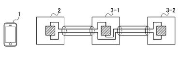
- FIGS. 1A to 1C are block diagrams showing the configuration of an information processing system according to an embodiment of the present invention.
- the information processing system shown in FIGS. 1A to 1C includes a user terminal 1 used by a user, a basic core 2, and a large number of functional modules 3-1 to 3-n (n is an arbitrary integer value of 1 or more). including.
- n is an arbitrary integer value of 1 or more.
- the present invention is not particularly limited thereto. Any number may be used.
- the number n of the functional modules 3-1 to 3-n connected to the basic core 2 is not particularly limited.
- N may be 2 as in the example of FIG. 1A
- n may be 3 as in the examples of FIG. 1B or 1C
- n may be another integer value.
- the user terminal 1 communicates with the basic core 2 using various methods, for example, various methods such as NFC (Near Field Communication), Bluetooth (R), and the like.
- various methods such as NFC (Near Field Communication), Bluetooth (R), and the like.
- NFC Near Field Communication
- R Bluetooth
- FIG. 1A to FIG. 1C three examples of daisy chain type, star type and loop type are illustrated as an example of the connection mode of the basic core 2 and the functional module 3.
- the basic core 2 is one end, one functional module 3-1 is connected to the one end, and the functional module 3-2 is further connected to the functional module 3-1,
- another functional module 3 (not shown) is connected to the functional module 3-2, which is a so-called connection type connection mode.
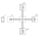
- the star type shown in FIG. 1B is a connection mode in which the basic core 2 and two or more functional modules 3 (three functional modules 3-1 to 3-3 in the example of FIG. 1B) are connected in a star type.
- the loop type shown in FIG. 1C the basic core 2 and one or more functional modules 3 are looped in a predetermined order (in the example of FIG. 1C, the order of the basic core 2 and the functional modules 3-1 to 3-3).
- connection aspect which is connected and comprises a closed loop.
- the wiring In the daisy chain type and star type, although the wiring apparently does not constitute a closed loop, the wiring is folded back in the basic core 2 or the functional module 3 located at the end, so the configuration is electrically closed loop wiring I am taking
- the connection mode is basically the above connection mode, but any connection mode can be adopted by combining the above connection modes, etc., as long as an electrically closed loop wiring configuration is adopted.
- the basic core 2 is a hardware device used by being connected to one or more functional modules 3 and is paired with the user terminal 1 by near field communication (for example, communication conforming to the NFC (registered trademark) standard) Do the ring.
- near field communication for example, communication conforming to the NFC (registered trademark) standard
- the user terminal 1 is connected to the basic core 2-K and the basic core 2-K by performing pairing with a predetermined basic core 2-K (K is an arbitrary integer value of 1 to m). It recognizes L (L is an arbitrary integer value) functional modules 3-K1 to 3-KL. That is, a target connected to the basic core 2-K may be a series connection of L functional modules 3. The user terminal 1 can recognize these L individual functional modules 3 individually.
- the functional module 3 is, for example, a hardware device configured by various sensors such as a temperature sensor, operation devices such as a push button, and driving devices such as a motor.
- pairing means making the user terminal 1 recognize the type and connection state of the basic core 2-K and the functional module 3 connected to it using near field communication.
- the H parts corresponding to the connected functional module 3 are displayed on the program preparation screen.
- FIG. 2 is a block diagram showing an example of a hardware configuration of a user terminal according to an embodiment of the present invention.
- the user terminal 1 is configured of a tablet terminal or the like.
- the user terminal 1 displays a central processing unit (CPU) 21, a read only memory (ROM) 22, a random access memory (RAM) 23, a bus 24, an input / output interface 25, a touch operation input unit 26, and a display. And an input unit 28, a storage unit 29, a first near-field wireless communication unit 30, a second near-field wireless communication unit 31, a communication unit 32, a drive 33, and a removable medium 34 There is.
- the CPU 21 executes various processes in accordance with a program stored in the ROM 22 or a program loaded from the storage unit 29 into the RAM 23.
- the RAM 23 appropriately stores information necessary for the CPU 21 to execute various processes.
- the CPU 21, the ROM 22 and the RAM 23 are mutually connected via a bus 24.
- the input / output interface 25 is also connected to the bus 24.
- the input / output interface 25 includes a touch operation input unit 26, a display unit 27, an input unit 28, a storage unit 29, a first short distance wireless communication unit 30, a second short distance wireless communication unit 31, a communication unit 32, and a drive 33. It is connected.
- the touch operation input unit 26 is formed of, for example, a capacitive or resistive (pressure-sensitive) position input sensor stacked on the display unit 27, and detects the coordinates of the position at which the touch operation is performed.
- the display unit 27 is configured of a display such as liquid crystal, and displays various images such as an image related to program preparation.
- the touch operation input unit 26 and the display unit 27 constitute a touch panel.
- the input unit 28 is configured by various hardware such as a button, and inputs various information in accordance with a user's instruction operation.
- the storage unit 29 is configured by a hard disk, a dynamic random access memory (DRAM), or the like, and stores various information.
- DRAM dynamic random access memory
- the first short distance wireless communication unit 30 executes control to perform short distance wireless communication, for example, according to the NFC (registered trademark) standard. Specifically, for example, as described above, the user terminal 1 and the basic core 2 perform short distance wireless communication in a method according to the NFC (registered trademark) standard to perform pairing.
- NFC registered trademark
- the second short distance wireless communication unit 31 executes control to perform short distance wireless communication, for example, according to the Bluetooth (registered trademark) standard. Specifically, for example, the execution result (including the command and the like) of the program created in the user terminal 1 is transmitted by near field communication of a method according to the standard of Bluetooth (registered trademark).
- the communication unit 32 independently controls the communication performed with another device via the Internet or the like separately from the first near-field wireless communication unit 30 and the second near-field wireless communication unit 31.
- the drive 33 is provided as needed.
- a removable medium 34 composed of a magnetic disk, an optical disk, a magneto-optical disk, a semiconductor memory or the like is appropriately attached to the drive 33.
- the program read from the removable media 34 by the drive 33 is installed in the storage unit 29 as needed.
- the removable media 34 can also store various information stored in the storage unit 29 in the same manner as the storage unit 29.
- FIG. 3 is a block diagram showing an example of a hardware configuration of a basic core according to an embodiment of the present invention.
- the basic core 2 is configured by a predetermined hardware device or the like.
- the basic core 2 includes a CPU 41, a ROM 42, a RAM 43, a bus 44, a first short distance wireless communication unit 45, a second short distance wireless communication unit 46, a connection unit 47, and a power supply unit 48.
- the CPU 41, the ROM 42, the RAM 43, the bus 44, the first short distance wireless communication unit 45, and the second short distance wireless communication unit 46 are basically the same as the configuration of the user terminal 1. , Here, their explanation is omitted.
- connection unit 47 performs connection with another hardware device (for example, the functional module 3 of FIGS. 1A to 1C).
- the connection unit 47 also includes an inter-module transmission unit 51 and a signal superposition unit 52.
- the inter-module transmission unit 51 executes control to perform data communication on the power line by, for example, a method using a 4-20 mA direct current signal or the like, and performs other hardware devices (for example, the functions of FIGS. 1A to 1C).
- the module 3) transmits various information (hereinafter appropriately referred to as “transmission information”) while supplying power by current. That is, the signal superimposing unit 52 separably superimposes predetermined information supplied to another hardware device (for example, the functional module 3 of FIGS. 1A to 1C) on the current supplied from the power supply unit 48 described later. .
- the current signal on which the transmission information is superimposed is transmitted from the inter-module transmission unit 51 to the functional module 3.
- the power supply unit 48 is a DC stabilized power supply, supplies power to the basic core 2, and appropriately supplies power to the functional module 3 via the inter-module transmission unit 51.
- FIG. 4 is a block diagram showing an example of a hardware configuration of a functional module according to an embodiment of the present invention.
- the functional module 3 is configured by a predetermined hardware device or the like.
- the functional module 3 includes a CPU 61, a ROM 62, a RAM 63, a bus 64, a connection unit 67, a functional hardware 68, and a power extraction unit 69.
- the CPU 61, the ROM 62, the RAM 63, and the bus 64 are basically the same as the configuration of the user terminal 1 or the basic core 2, and thus the description thereof is omitted here.
- connection unit 67 performs connection with another hardware device (for example, the basic core 2 or the other functional module 3 in FIGS. 1A to 1C).
- the connection unit 67 further includes an inter-module transmission unit 71 and a signal separation unit 72.
- the inter-module transmission unit 71 executes control to perform data communication on the power line by, for example, a method using a 4-20 mA direct current signal or the like, and performs the first other hardware device (for example, basic core 2 or the like). Power from the current supplied from the first other functional module 3) is received and supplied to the power extraction unit 69, and to the second other hardware device (for example, the second other functional module 3) Transmit
- the signal separation unit 72 transmits transmission information (for example, its own device) to the signal of the current supplied from the first other hardware device (for example, the basic core 2 or the first other functional module 3). When a command or the like to the functional hardware 68 is superimposed, the transmission information is separated and supplied to the functional hardware 68 or the like.
- the functional hardware 68 is, for example, a temperature sensor or a buzzer, and hardware or the like for each functional module to exhibit a unique function, and based on information such as a command supplied from the signal separation unit 72 Bring out the function. That is, the program created by the user is reflected on the actual hardware by the functional hardware 68 appropriately performing its function.
- the power extraction unit 69 supplies the functional module 3 with the power acquired through the inter-module transmission unit 71 or the power supplied from an external power supply (for example, the battery unit BU in FIG. 5).
- the functional module 3 may also be provided with a first near-field wireless communication unit and a second near-field wireless communication unit.
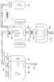
- FIG. 5 is a diagram showing an example of a configuration in a state in which a basic core and a functional module according to an embodiment of the present invention are connected.
- FIG. 5 illustrates a basic core 2-E, a functional module 3-E1, a functional module 3-E2, and a battery unit PP.
- the battery unit BU for example, the power supply unit 48 in FIG. 6
- the serial ports SP1 and SP2 and the short distance wireless communication unit BT for example, the second short distance wireless communication unit 46 in FIG. 6) It is equipped.
- the battery unit BU is, for example, a DC stabilized power supply, and supplies power to the basic core 2-E, the functional module 3-E1 and the functional module 3-E2 by current.
- the serial ports SP1 and SP2 are connection ports (connection connectors) for connecting the basic core 2-E and other hardware or the like.
- the basic core 2-E is provided with serial ports SP1 and SP2, and the functional module 3-E1 is provided with a serial port PS1.
- the basic core 2-E and the functional module 3-E1 are connected via the two serial ports SP1 and PS1.
- the functional module 3-E1 is provided with the serial port PS2, and the functional module 3-E2 is provided with the serial port PS3, and the functional module 3-E1 and the functional module 3-E2 are provided with the two serial ports PS2, Connected via PS3.
- a plurality of modules may be connected in a loop via the functional module 3 located at the end connected in series from the serial port SP1 and the serial port.
- the short distance wireless communication unit BT is mounted with an IC card or the like for performing short distance wireless communication in accordance with another hardware or the like and a predetermined standard (for example, Bluetooth (registered trademark)).
- the user terminal 1 (not shown in FIG. 5) and the basic core 2-E provided with the short distance wireless communication unit BT are in the short distance according to the Bluetooth (registered trademark) system. Perform wireless communication. Specifically, for example, the execution result (command or the like) of the program created in the user terminal 1 is also transmitted to the basic core 2-E.
- the Bluetooth registered trademark
- basic core 2-E acquires the execution result (such as a command) of the program transmitted from user terminal 1, and further superimposes the result on the current signal (for power supply) as transmission information. Then, among the functional modules 3-E1 and 3-E2, the functional module 3 is transmitted to the target functional module 3 such as a command.
- the functional module 3-E1 is provided with a tire T (for example, the functional hardware 68a of FIG. 4), and the functional module 3-E2 is provided with a buzzer (for example, the functional hardware 68b of FIG. 4).
- the functional modules 3-E1 and 3-E2 acquire only the execution result (command etc.) of the program for the own machine among the transmission information transmitted from the basic core 2-E.
- the functional module 3-E1 in the example of FIG. 5 drives the tire T in accordance with a command or the like for driving the tire among execution results (commands and the like) of the program produced by the user terminal 1.
- the functional module 3-E2 causes the buzzer to sound according to a command or the like for making the buzzer sound out of the execution results (commands and the like) of the program produced by the user terminal 1.
- the battery unit PP is connected to the functional module 3-E1.
- the battery unit PP supplies power to the functional module 3-E1 as an external power supply, and further supplies power to the functional module 3-E2 and the like connected to the functional module 3-E1.
- the battery unit PP is an essential component. Absent.
- the program preparation process is a process for preparing a program for causing one or more of the functional modules 3 connected to the basic core 2 to function.
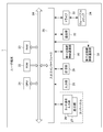
- FIG. 6 is a functional block diagram showing a functional configuration example of the user terminal of FIG. 2, the basic core of FIG. 3 and the functional module of FIG.
- the pairing unit 101, the program preparation unit 102, the program execution unit 103, the display control unit 104, and the communication control unit 105 function.
- a program storage unit 500 for storing the program prepared by the program preparation unit 102 in one area of the storage unit 29 of the user terminal 1 and an S-parts DB in which various S parts are stored And 600) are provided.
- the pairing unit 201, the terminal communication control unit 202, the functional module communication control unit 203, and the main control unit 204 function. Further, in the CPU 61a of the functional module 3a, the main control unit 242a and the function exerting unit 243a function.
- the functional module 3 may further exist, but is not shown because it has the same configuration.
- the pairing unit 101 of the user terminal 1 performs pairing between the user terminal 1 and the basic core 2 via the first short distance wireless communication unit 30.
- this pairing is performed by near field communication based on NFC (registered trademark) in this embodiment, this is merely an example, and communication may be performed by any method.
- the pairing unit 101 confirms the type and connection status of the basic core 2 paired with the user terminal 1 and the functional module 3 connected thereto.
- the type of the functional module 3 confirmed by the pairing unit 101 and the connection status are displayed on the program preparation screen via the display control unit 104.
- the program creation unit 102 receives a user's touch operation and actually creates a program.
- Program preparation unit 102 displays H parts corresponding to the type of functional module 3 connected to basic core 2 that has been paired by pairing unit 101 on the program preparation screen via display control unit 104. .
- the program creation unit 102 appropriately extracts the S parts from the S parts DB 600 and displays them on the program creation screen via the display control unit 104.
- the program creation unit 102 combines various H parts and various S parts according to the touch operation of the user. In the program finally produced, the contents of the program designated for the various H parts and S parts thus combined are continuously executed.
- Program preparation unit 102 determines the contents of the program prepared by the user, and stores the prepared program in program storage unit 500.
- the program execution unit 103 extracts and executes a program which the user desires to execute out of the programs stored in the program storage unit 500.
- the program execution unit 103 executes a program for the purpose of operating the basic core 2 and the functional module 3 by the program created by the user. That is, the program execution unit 103 transmits an execution result (such as a command) of the created program to the basic core 2 and the functional module 3 to cause the functional module 3 to exhibit the function.
- an execution result such as a command
- the execution result of the program is not only displayed on the display unit 27 via the display control unit 104, but also transmitted to the basic core 2 by the communication control unit 105 as described later.
- the display control unit 104 executes control for displaying the above-described various information and the like on the display unit 27.
- the communication control unit 105 performs control for transmitting the execution result of the program executed by the program execution unit 103 to the basic core 2 via the second short distance wireless communication unit 31.
- the second short distance wireless communication unit 31 performs short distance wireless communication in accordance with the Bluetooth (registered trademark) standard.
- the pairing unit 201 of the basic core 2 performs short-range wireless communication of a predetermined system via the first short-distance wireless communication unit 45 and the user terminal 1 that executes control for causing the functional module 3 to exhibit the predetermined function. Perform pairing.
- the first short distance wireless communication unit 45 is independent of the system in the basic core 2. Therefore, connection information (for example, MAC address) of the second near-field wireless communication unit 46 is written in advance in the first near-field wireless communication unit 45, and the pairing unit 201 reads the MAC address and performs Bluetooth.
- the pairing with the user terminal 1 is realized by (registered trademark).
- the terminal communication control unit 202 executes, for example, control for acquiring the execution result of the program transmitted from the user terminal 1 via the second short distance wireless communication unit 46.
- the functional module 3 that causes the program to exhibit a function needs to be connected to a predetermined basic core 2. That is, at least at the time of executing a program, the basic core 2 and the functional module 3 are connected by the connection unit 47 and the connection unit 67.
- connection between the basic core 2 and the functional module 3 can be performed independently of the pairing between the basic core 2 and the user terminal 1. That is, although the connection between the basic core 2 and the functional module 3 may be made before pairing, the connection between the basic core 2 and the functional module 3 may be made after pairing.
- the user terminal 1 recognizes what the functional module 3 is (what function is to be exhibited) by transmitting its own unique ID from the functional module 3 to the user terminal 1 Can. Also, the functional module 3 can be removed from the basic core 2 after pairing.
- the basic core 2 notifies the user terminal 1 that the functional module 3 has been disconnected.
- the user terminal 1 causes the display unit 27 (a user display screen of FIG. 8A to FIG. 8C described later, etc.) to display that the user terminal 1 has deviated. More precisely, in the present embodiment, when the predetermined functional module 3 is removed from the basic core 2, the user terminal 1 does not display an icon indicating the H part corresponding to the predetermined functional module 3 in the display unit 27. Set to display state.
- the functional module communication control unit 203 of the basic core 2 executes control of communication with the functional module 3 connected via the connection unit 47.
- the functional module communication control unit 203 transmits, to the functional module 3, an operation instruction or the like output by the main control unit 204 described later. That is, the functional module communication control unit 203 superimposes transmission information on a current signal for supplying power to one or more functional modules 3 in a current system, and performs control to transmit the information to the one or more functional modules 3.
- the functional module communication control unit 203 is provided with a transmission information generation unit 211.
- the transmission information generation unit 211 is predetermined information used by the functional module 3 to cause or exhibit a predetermined function based on the control of the user terminal 1, and information indicating a transmission destination among the one or more functional modules 3 and To generate transmission information including
- the main control unit 204 performs main control of various processes executed by the basic core 2. For example, the main control unit 204 outputs, based on the execution result of the program acquired by the terminal communication control unit 202, an operation instruction or the like for exhibiting the function of the functional module 3.
- the functional module 3a also has the same configuration, and therefore redundant description will be omitted unless otherwise specified.
- the main control unit 242a of the functional module 3 performs main control of various processes executed by the functional module 3a. For example, the main control unit 242a acquires an operation instruction (such as a command) transmitted as transmission information from the basic core 2 via the connection unit 67a.
- an operation instruction such as a command
- the function exerting unit 243a executes control for causing the function hardware 68a to execute based on the operation instruction acquired by the main control unit 242a. That is, the function exerting unit 243a causes the function hardware 68a to be executed based on the operation instruction acquired by the main control unit 242a to exhibit the function of the function module 3a.
- FIG. 6 only shows how the power extraction unit 69a supplies the power obtained through the inter-module transmission unit 71a to the functional module 3a, as described above, an external power supply (for example, It is also possible to supply the power supplied from the 5 battery units BU) to the functional module 3a.
- an external power supply for example, It is also possible to supply the power supplied from the 5 battery units BU to the functional module 3a.
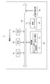
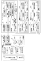
- FIG. 7 is an arrow chart for explaining the flow of processing between modules.
- step Sc1 the main control unit 204 (FIG. 6) of the basic core 2 receives control command information on the function control of the functional module 3b from the user terminal 1 via the terminal communication control unit 202.
- step Sc2 the transmission information generation unit 211 (FIG. 6) of the functional module communication control unit 203 of the basic core 2 mixes the control information received in step Sc1 and information indicating that the destination is the functional module 3b. The combined data is generated as transmission information.
- the signal superposition unit 52 superimposes the transmission information on the current for power supply from the power supply unit 48.
- the inter-module transmission unit 51 transmits the signal of the current on which the transmission information is superimposed.
- step Sa1 the inter-module transmission unit 71a (FIG. 6) of the connection unit 67a of the functional module 3a detects the signal of the current transmitted from the basic core 2.
- step Sa2 the signal separation unit 72a (FIG. 6) of the functional module 3a analyzes the signal of the detected current and determines that it is not a control signal (transmission information) to its own device because the destination is not the own device. Do. In this case, the power extraction unit 69a acquires the power via the inter-module transmission unit 71a and supplies the power to the functional module 3a.
- step Sb1 the inter-module transmission section 71b (FIG. 6) of the connection section 67b of the functional module 3b detects the signal of the current transmitted from the basic core 2 via the functional module 3a.
- step Sb2 the signal separation unit 72b (FIG. 6) of the functional module 3b analyzes the signal of the detected current and includes the own machine at the destination, so that it is a control signal (transmission information) to the own machine judge. Then, the signal separation unit 72 b separates the control signal (transmission information) and supplies it to the functional hardware 68 b or the like. Further, the power extraction unit 69b acquires the power via the inter-module transmission unit 71b, and supplies the power to the functional module 3a.
- step Sb3 the main control unit 242b and the function exerting unit 243b (FIG. 6) of the function module 3b execute control to turn on / off the function of the function hardware based on the control signal.
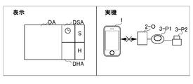
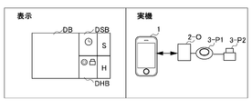
- FIGS. 8A to 8C are diagrams showing an example of a screen actually displayed to the user in the program preparation process executed by the user terminal 1 of FIG.
- FIG. 8A shows a state in which the user terminal 1 is not paired with any basic core 2.
- the basic core 2-O (O is an arbitrary integer value of 1 to m)
- the functional module 3-P1 (P1 and P2 are arbitrary integer values) is paired.
- the functional module 3-P1 can exhibit the light function.
- the functional module 3-P2 can exhibit the function of a buzzer.
- FIG. 8B shows a state in which the user terminal 1 is paired with the basic core 2-O to which the functional module 3-P1 and the functional module 3-P2 are connected. Then, when looking at the user display screen of FIG. 8B, the icon of the light corresponding to the function module 3-P1 which has been paired and the icon of the buzzer corresponding to the function module 3-P2 are respectively displayed in the H parts display area DHB. ing.
- FIG. 8C shows a situation where a program created by the user has been executed.
- the user display screen shown in FIG. 8C is viewed, light icons, timers 2s, and buzzer icons are displayed in order from the right in the program creation display area DC, and the respective icons are connected in order by the arrows. There is.
- the present invention is not limited to the above-described embodiment, and any modification, improvement, etc. within the range in which the object of the present invention can be achieved is included in the present invention. is there.
- a light and a buzzer are adopted as the functional module 3-P1 and the functional module 3-P2, but the function exerted by the functional module 3 is not particularly limited to the above-described embodiment.
- the power supply unit 48 adopts a battery capable of supplying a stable direct current, but the supplied current is not limited to direct current, and The alternating current may be supplied by adopting any means.
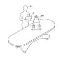
- 9A and 9B are diagrams showing a specific example according to an embodiment of the present invention.
- the toy of the rocket with a propeller is employ
- a program is created and executed such that the propeller rotates after a 10-second countdown.
- the basic core B1 connected to the functional module M1 and the functional module MC (for example, a speaker or the like) that exhibits the countdown function are not illustrated, but are stored, for example, in the functional module M1.
- a train toy is adopted as the functional module M1.
- a program is generated and executed in which a train is started in response to human voice or the like.
- the basic core B2 connected to the functional module M2 and the functional module MA (for example, an audio sensor) that exhibits the function of capturing a sound are not illustrated, for example, It is stored inside module M2.
- the present invention can be practiced in a variety of such forms, but in many embodiments is particularly useful for creating programs for use in children's educational toys.
- the program creation screen can be visually confirmed, the program can be created safely and easily even if the user is a child, and according to the program created by oneself. Because it can be operated by a real machine, children can enjoy making programs without getting bored. In this way, having the children create programs while having fun allows them to become familiar with programs that are generally difficult to touch.
- the input / output information in the present embodiment will be supplemented.
- the contents of the program designated by the various icons are continuously executed.
- As input / output information of each program not only simple trigger information as shown in FIG. 8A to FIG. 8C but also a wide variety of information such as analog signals can be handled as input / output information. That is, for example, the input / output information in this embodiment can be used for producing a program by outputting information (for example, a temperature of 15 degrees) acquired by the temperature sensor as it is as information such as an analog signal. Therefore, it is possible to realize even complex information processing that can not be realized only by information of digital signals.
- pairing of user terminal 1 and basic core 2 is performed by near field communication by a method according to NFC (registered trademark) standard, it is not limited to this.
- the pairing is not limited to near field communication, and may be performed by any means.
- the execution result of the program produced by the user terminal 1 is transmitted using the short distance wireless communication in a method according to the standard such as Bluetooth (registered trademark), in particular It is not limited to.
- the created program is not limited to near field communication, and may be transmitted using any means.
- the number of basic cores 2 and the number of functional modules 3 are not limited to the above-described embodiment. That is, the number of basic cores 2 and the number of functional modules 3 may be the same or different. That is, one functional module 3 may be connected to one basic core 2.
- the transmission information is generated and transmitted by the basic core 2 and received by the functional module 3, but the present invention is not particularly limited thereto.
- the transmission information may be generated and transmitted by the functional module 3, and may be received by the basic core 2 or another functional module 3.
- a signal transmitted from the basic core 2 to supply power to one or more functional modules 3 may be an alternating current even if it is a direct current as long as it can transmit the power by a current method. May be
- the series of processes described above can be performed by hardware or software.
- the functional configuration of FIG. 6 is merely illustrative and not particularly limited. That is, it is sufficient if the information processing system is provided with a function capable of executing the above-described series of processes as a whole, and what functional block is used to realize this function is not particularly limited to the example of FIG. Also, the location of the functional block is not particularly limited to that in FIG. 6, and may be arbitrary. Further, one functional block may be configured by hardware alone, may be configured by software alone, or may be configured by a combination of them.
- a program configuring the software is installed on a computer or the like from a network or a recording medium.
- the computer may be a computer incorporated in dedicated hardware.
- the computer may be a computer capable of executing various functions by installing various programs, such as a general-purpose smartphone or personal computer other than a server.
- a recording medium including such a program is not only configured by a removable medium (not shown) distributed separately from the apparatus main body to provide the program to the user, but is also incorporated in the apparatus main body in advance. And a recording medium provided to the user.
- the processing performed chronologically along the order is, of course, parallel or individually not necessarily necessarily chronologically processing. It also includes the processing to be performed.
- the term "system” is intended to mean an overall device composed of a plurality of devices, a plurality of means, and the like.
- the information processing apparatus to which the present invention is applied can take various embodiments having the following configuration. That is, the information processing apparatus to which the present invention is applied (for example, the basic core 2 of FIG. 6) is The information processing apparatus for performing information communication and power supply to one or more other information processing apparatuses (for example, functional modules 3a and 3b in FIG. 6) that exhibit predetermined functions, respectively.
- a control device for example, the user terminal 1 that executes control for causing the other information processing apparatus to exhibit the predetermined function and pairing execution means (for example, FIG. 6) for pairing with near field communication of a predetermined method.
- Transmission information generation means for example, transmission information generation unit 211 in FIG. 6 for generating transmission information including Transmission control means (for example, control for executing control to transmit the transmission information to the one or more other information processing devices by superimposing the transmission information on a signal for supplying power to the one or more other information processing devices in a current system , Connection portion 47) of FIG. It is sufficient if it is a control device provided with Thus, the user can create the program by easy operation (such as combining and connecting icons) while visually confirming the contents of the program to be created. This also provides a technology that can implement many functions with a small number of devices. This also provides a technology capable of stabilizing data communication with a simple configuration.
Abstract
The purpose of the present invention is to enable a user to create a program with visual operations, and to enable the stable implementation of many functions with a small number of devices. In a basic core 2, a pairing unit 201 executes pairing with a user terminal 1 that executes control for causing functional modules 3a, 3b to exhibit prescribed functions. A transmission information generation unit 211 generates transmission information including: prescribed information to be used by the functional modules 3a, 3b to exhibit the prescribed functions or while exhibiting the prescribed functions on the basis of the control by the user terminal 1; and information indicating a transmission destination, which is one of the functional modules 3a, 3b. A connection unit 47 executes control to superimpose the transmission information on a signal for supplying power to the functional modules 3a, 3b in the form of electric current and to transmit the signal to the functional modules 3a, 3b.
Description
本発明は、情報処理装置に関する。
The present invention relates to an information processing apparatus.
従来から、子供の教育を目的とした組み立て式玩具は、広く普及しており、関連する技術は数多く提案されている(例えば、特許文献1参照)。
例えば、特許文献1に記載された技術によれば、簡単な配線やプログラミングによって組み立て式玩具を構築することができる組み立てブロックの提供がなされている。
この特許文献1に記載された技術によれば、年齢の低いユーザであっても、複雑な作業や操作を行うことなく、組み立て式玩具を構築することができる。 2. Description of the Related Art Conventionally, assembly-type toys intended for children's education are widely used, and many related techniques have been proposed (see, for example, Patent Document 1).
For example, according to the technology described inPatent Document 1, there is provided an assembly block capable of constructing an assemblable toy by simple wiring and programming.
According to the technology described inPatent Document 1, even an age-old user can construct an assembly-type toy without performing complicated operations and operations.
例えば、特許文献1に記載された技術によれば、簡単な配線やプログラミングによって組み立て式玩具を構築することができる組み立てブロックの提供がなされている。
この特許文献1に記載された技術によれば、年齢の低いユーザであっても、複雑な作業や操作を行うことなく、組み立て式玩具を構築することができる。 2. Description of the Related Art Conventionally, assembly-type toys intended for children's education are widely used, and many related techniques have been proposed (see, for example, Patent Document 1).
For example, according to the technology described in
According to the technology described in
しかしながら、上述の特許文献1の技術では、各組み立てブロックは、既存のプログラムによって単一に制御されているに過ぎず、組み立て式玩具の動作や制御の自由度には、限界があった。
即ち、例えば、上述の特許文献1の技術のみでは、各組み立てブロックの夫々の機能を組み合わせて、プログラムを作製するような処理を実行することはできなかった。
換言すれば、上述の特許文献1の技術のみでは、各組み立てブロックの夫々の機能を組み合わせるといった高度な処理を実行させるためには、別途、複雑なプログラムを作成する必要があった。
また従来の各組み立てブロックでは、電力線と通信線を別個に配線していた。この方式は、配線数が多いことにより1本に纏める等した場合にケーブルが太くなりがちであり、配線のとり回しが悪くなる。また、接続コネクタも必要になるという制約が出てしまう。また従来の各組み立てブロックでは、電圧型通信方式が採用されていた。この方式は、長距離で安定して通信する場合は、回路が複雑化しやすく、コストや基板サイズが肥大化してしまう。つまり、従来の各組み立てブロックでは、簡単な構成でデータ通信を安定させることは困難であった。 However, in the technology ofPatent Document 1 described above, each assembly block is controlled solely by the existing program, and there is a limit to the freedom of operation and control of the assembly type toy.
That is, for example, with the technology ofPatent Document 1 described above alone, it has not been possible to execute processing such as creating a program by combining the respective functions of the respective assembly blocks.
In other words, with the technology ofPatent Document 1 described above, it is necessary to separately create a complicated program in order to execute high-level processing such as combining the respective functions of the building blocks.
In each of the conventional assembly blocks, power lines and communication lines are wired separately. In this method, the cable tends to be thick when combined into one cable due to the large number of wires, and the routing of the wires becomes worse. In addition, there is a restriction that a connection connector is also required. Further, in each of the conventional assembly blocks, a voltage type communication system has been adopted. In this method, when communicating stably over a long distance, the circuit is easily complicated, and the cost and the size of the substrate are increased. That is, in each of the conventional assembly blocks, it is difficult to stabilize data communication with a simple configuration.
即ち、例えば、上述の特許文献1の技術のみでは、各組み立てブロックの夫々の機能を組み合わせて、プログラムを作製するような処理を実行することはできなかった。
換言すれば、上述の特許文献1の技術のみでは、各組み立てブロックの夫々の機能を組み合わせるといった高度な処理を実行させるためには、別途、複雑なプログラムを作成する必要があった。
また従来の各組み立てブロックでは、電力線と通信線を別個に配線していた。この方式は、配線数が多いことにより1本に纏める等した場合にケーブルが太くなりがちであり、配線のとり回しが悪くなる。また、接続コネクタも必要になるという制約が出てしまう。また従来の各組み立てブロックでは、電圧型通信方式が採用されていた。この方式は、長距離で安定して通信する場合は、回路が複雑化しやすく、コストや基板サイズが肥大化してしまう。つまり、従来の各組み立てブロックでは、簡単な構成でデータ通信を安定させることは困難であった。 However, in the technology of
That is, for example, with the technology of
In other words, with the technology of
In each of the conventional assembly blocks, power lines and communication lines are wired separately. In this method, the cable tends to be thick when combined into one cable due to the large number of wires, and the routing of the wires becomes worse. In addition, there is a restriction that a connection connector is also required. Further, in each of the conventional assembly blocks, a voltage type communication system has been adopted. In this method, when communicating stably over a long distance, the circuit is easily complicated, and the cost and the size of the substrate are increased. That is, in each of the conventional assembly blocks, it is difficult to stabilize data communication with a simple configuration.
本発明は、このような状況に鑑みてなされたものであり、ユーザが視覚的な操作よって、より容易に複雑なプログラムを作製することが出来るようになることを目的とする。
また本発明は、少数の機器で、多数の機能を実装させることも目的とする。
また本発明は、少数の機器で、多数の機能を実装させることができる。
また本発明によれば、簡単な構成でデータ通信を安定させることができる。 The present invention has been made in view of such circumstances, and it is an object of the present invention to allow a user to easily create a complicated program by visual operation.
Another object of the present invention is to implement a large number of functions with a small number of devices.
Also, the present invention can implement many functions with a small number of devices.
Further, according to the present invention, data communication can be stabilized with a simple configuration.
上記目的を達成するため、本発明の一態様の情報処理装置は、
所定の機能を夫々発揮する1以上の他の情報処理装置に対して情報通信及び電力供給を行う情報処理装置であって、
前記他の情報処理装置に前記所定の機能を発揮させるための制御を実行する制御装置と、所定方式の近距離無線通信でペアリングするペアリング実行手段と、
前記制御装置の制御に基づき前記他の情報処理装置が前記所定の機能を発揮させるために又は発揮中に用いる所定の情報と、前記1以上の他の情報処理装置のうち送信先を示す情報とを含む送信情報を生成する送信情報生成手段と、
電流方式で電力を前記1以上の他の情報処理装置に供給するための信号に、前記送信情報を重畳して、前記1以上の他の情報処理装置に送信する制御を実行する送信制御手段と、
を備える。 In order to achieve the above object, an information processing apparatus according to an aspect of the present invention is
An information processing apparatus that performs information communication and power supply to one or more other information processing apparatuses that exhibit predetermined functions.
A control device that executes control for causing the other information processing apparatus to exhibit the predetermined function, and pairing execution means that performs pairing by near-field wireless communication of a predetermined method;
Predetermined information used by the other information processing apparatus to cause or cause the predetermined function to be performed based on control of the control apparatus, and information indicating a transmission destination among the one or more other information processing apparatuses Transmission information generation means for generating transmission information including:
Transmission control means for executing control to superimpose the transmission information on a signal for supplying power to the one or more other information processing devices in a current system, and to transmit the information to the one or more other information processing devices ,
Equipped with
本発明の一態様の情報処理方法及びプログラムも、本発明の一態様の情報処理装置に対応する情報処理方法及びプログラムとして提供される。
The information processing method and program according to an aspect of the present invention are also provided as an information processing method and program corresponding to the information processing apparatus according to an aspect of the present invention.
本発明によれば、ユーザが視覚的な操作よって、より容易に複雑なプログラムを作製することが出来る技術を提供することができる。
また本発明によれば、少数の機器で、多数の機能を実装させることができる。
また本発明によれば、電力線通信が導入されているので、2本の線のみで電力供給と通信が可能となる。また本発明によれば、電流型通信が導入されているので、ノイズに強くシンプルな回路を組むことが可能になる。つまり、本発明によれば、簡単な構成でデータ通信を安定させることができる。 According to the present invention, it is possible to provide a technique that allows a user to create a complicated program more easily by visual operation.
Furthermore, according to the present invention, a large number of functions can be implemented by a small number of devices.
Further, according to the present invention, since power line communication is introduced, power supply and communication can be performed with only two lines. Further, according to the present invention, since current communication is introduced, it is possible to build a simple circuit resistant to noise. That is, according to the present invention, data communication can be stabilized with a simple configuration.
以下、本発明の実施形態について、図面を用いて説明する。
Hereinafter, embodiments of the present invention will be described using the drawings.
図1A乃至図1Cは、本発明の一実施形態に係る情報処理システムの構成を示すブロック図である。
図1A乃至図1Cに示す情報処理システムは、ユーザにより使用されるユーザ端末1と、ベーシックコア2と、多数の機能モジュール3-1乃至3-n(nは1以上の任意の整数値)とを含む。
なお、ユーザ端末1とベーシックコア2との夫々は、図1A乃至図1Cの例では説明の便宜上1台のみ図示されているが、特にこれに限定されず、後述するペアリングが可能であれば任意の台数でよい。
また、ベーシックコア2に接続される機能モジュール3-1乃至3-nの台数nは、特に限定されない。図1Aの例のようにn=2であってもよいし、図1Bや図1Cの例のようにn=3であってもよいし、nはその他の整数値であってもよい。 1A to 1C are block diagrams showing the configuration of an information processing system according to an embodiment of the present invention.
The information processing system shown in FIGS. 1A to 1C includes auser terminal 1 used by a user, a basic core 2, and a large number of functional modules 3-1 to 3-n (n is an arbitrary integer value of 1 or more). including.
Note that although only oneuser terminal 1 and one basic core 2 are illustrated in the example of FIGS. 1A to 1C for convenience of explanation in the example of FIGS. 1A to 1C, the present invention is not particularly limited thereto. Any number may be used.
Further, the number n of the functional modules 3-1 to 3-n connected to thebasic core 2 is not particularly limited. N may be 2 as in the example of FIG. 1A, n may be 3 as in the examples of FIG. 1B or 1C, and n may be another integer value.
図1A乃至図1Cに示す情報処理システムは、ユーザにより使用されるユーザ端末1と、ベーシックコア2と、多数の機能モジュール3-1乃至3-n(nは1以上の任意の整数値)とを含む。
なお、ユーザ端末1とベーシックコア2との夫々は、図1A乃至図1Cの例では説明の便宜上1台のみ図示されているが、特にこれに限定されず、後述するペアリングが可能であれば任意の台数でよい。
また、ベーシックコア2に接続される機能モジュール3-1乃至3-nの台数nは、特に限定されない。図1Aの例のようにn=2であってもよいし、図1Bや図1Cの例のようにn=3であってもよいし、nはその他の整数値であってもよい。 1A to 1C are block diagrams showing the configuration of an information processing system according to an embodiment of the present invention.
The information processing system shown in FIGS. 1A to 1C includes a
Note that although only one
Further, the number n of the functional modules 3-1 to 3-n connected to the
ユーザ端末1は、ベーシックコア2と、各種方式、例えばNFC(登録商標)(Near Field Communication)、Bluetooth(登録商標)等の各種方式で通信を行う。
なお、以下、機能モジュール3-1乃至3-nを個々に区別する必要がない場合、これらをまとめて「機能モジュール3」と呼ぶ。
図1A乃至図1Cにおいて、ベーシックコア2と機能モジュール3の接続態様の例として、ディジーチェーン型、スター型及びループ型の3つが例示されている。
図1Aに示すディジーチェーン型は、ベーシックコア2が一端となって、当該一端に1台の機能モジュール3-1が接続され、当該機能モジュール3-1に更に機能モジュール3-2が接続され、さらには当該機能モジュール3-2に図示せぬ別の機能モジュール3が接続されてゆく、いわゆる芋づる式の接続態様である。
図1Bに示すスター型は、ベーシックコア2と、2台以上の機能モジュール3(図1Bの例では3台の機能モジュール3-1乃至3-3)がスター型に接続される接続態様である。
図1Cに示すループ型は、ベーシックコア2と、1以上の機能モジュール3とが所定順番(図1Cの例では、ベーシックコア2、機能モジュール3-1乃至3-3の順番)に輪になって接続され、閉ループを構成する接続態様である。
ディジーチェーン型及びスター型は、外見上配線が閉ループを構成していないが、端部に位置するベーシックコア2又は機能モジュール3において配線が折り返されているため、電気的には閉ループ配線となる構成をとっている。
接続態様は、以上の接続態様が基本であるが、電気的に閉ループ配線となる構成を取れば、以上の接続態様を複合させる等して任意の接続形態を採用することができる。 Theuser terminal 1 communicates with the basic core 2 using various methods, for example, various methods such as NFC (Near Field Communication), Bluetooth (R), and the like.
Hereinafter, when there is no need to distinguish the functional modules 3-1 to 3-n individually, they will be collectively referred to as "functional module 3".
In FIG. 1A to FIG. 1C, three examples of daisy chain type, star type and loop type are illustrated as an example of the connection mode of thebasic core 2 and the functional module 3.
In the daisy chain type shown in FIG. 1A, thebasic core 2 is one end, one functional module 3-1 is connected to the one end, and the functional module 3-2 is further connected to the functional module 3-1, In addition, another functional module 3 (not shown) is connected to the functional module 3-2, which is a so-called connection type connection mode.
The star type shown in FIG. 1B is a connection mode in which thebasic core 2 and two or more functional modules 3 (three functional modules 3-1 to 3-3 in the example of FIG. 1B) are connected in a star type. .
In the loop type shown in FIG. 1C, thebasic core 2 and one or more functional modules 3 are looped in a predetermined order (in the example of FIG. 1C, the order of the basic core 2 and the functional modules 3-1 to 3-3). It is the connection aspect which is connected and comprises a closed loop.
In the daisy chain type and star type, although the wiring apparently does not constitute a closed loop, the wiring is folded back in thebasic core 2 or the functional module 3 located at the end, so the configuration is electrically closed loop wiring I am taking
The connection mode is basically the above connection mode, but any connection mode can be adopted by combining the above connection modes, etc., as long as an electrically closed loop wiring configuration is adopted.
なお、以下、機能モジュール3-1乃至3-nを個々に区別する必要がない場合、これらをまとめて「機能モジュール3」と呼ぶ。
図1A乃至図1Cにおいて、ベーシックコア2と機能モジュール3の接続態様の例として、ディジーチェーン型、スター型及びループ型の3つが例示されている。
図1Aに示すディジーチェーン型は、ベーシックコア2が一端となって、当該一端に1台の機能モジュール3-1が接続され、当該機能モジュール3-1に更に機能モジュール3-2が接続され、さらには当該機能モジュール3-2に図示せぬ別の機能モジュール3が接続されてゆく、いわゆる芋づる式の接続態様である。
図1Bに示すスター型は、ベーシックコア2と、2台以上の機能モジュール3(図1Bの例では3台の機能モジュール3-1乃至3-3)がスター型に接続される接続態様である。
図1Cに示すループ型は、ベーシックコア2と、1以上の機能モジュール3とが所定順番(図1Cの例では、ベーシックコア2、機能モジュール3-1乃至3-3の順番)に輪になって接続され、閉ループを構成する接続態様である。
ディジーチェーン型及びスター型は、外見上配線が閉ループを構成していないが、端部に位置するベーシックコア2又は機能モジュール3において配線が折り返されているため、電気的には閉ループ配線となる構成をとっている。
接続態様は、以上の接続態様が基本であるが、電気的に閉ループ配線となる構成を取れば、以上の接続態様を複合させる等して任意の接続形態を採用することができる。 The
Hereinafter, when there is no need to distinguish the functional modules 3-1 to 3-n individually, they will be collectively referred to as "
In FIG. 1A to FIG. 1C, three examples of daisy chain type, star type and loop type are illustrated as an example of the connection mode of the
In the daisy chain type shown in FIG. 1A, the
The star type shown in FIG. 1B is a connection mode in which the
In the loop type shown in FIG. 1C, the
In the daisy chain type and star type, although the wiring apparently does not constitute a closed loop, the wiring is folded back in the
The connection mode is basically the above connection mode, but any connection mode can be adopted by combining the above connection modes, etc., as long as an electrically closed loop wiring configuration is adopted.
ここで、本実施形態で用いられる、ベーシックコア2及び機能モジュール3について簡単に説明する。
ベーシックコア2とは、1以上の機能モジュール3と接続して使用するハードウェアデバイスであり、近距離無線通信(例えば、NFC(登録商標)の規格に準拠した通信)でユーザ端末1とのペアリングを行う。 Here, thebasic core 2 and the functional module 3 used in the present embodiment will be briefly described.
Thebasic core 2 is a hardware device used by being connected to one or more functional modules 3 and is paired with the user terminal 1 by near field communication (for example, communication conforming to the NFC (registered trademark) standard) Do the ring.
ベーシックコア2とは、1以上の機能モジュール3と接続して使用するハードウェアデバイスであり、近距離無線通信(例えば、NFC(登録商標)の規格に準拠した通信)でユーザ端末1とのペアリングを行う。 Here, the
The
ユーザ端末1は、所定のベーシックコア2-K(Kは、1乃至mのうち任意の整数値)とペアリングを行うことで、ベーシックコア2-Kと、ベーシックコア2-Kと接続されたL個(Lは、任意の整数値)の機能モジュール3-K1乃至3-KLとを認識する。
つまり、ベーシックコア2-Kと接続される対象は、L個の機能モジュール3の直列接続で良い。ユーザ端末1は、これらをL個のそれぞれの機能モジュール3を個別に認識することができる。
機能モジュール3とは、例えば、温度センサ等の各種センサ、プッシュボタン等の操作器具、モーター等の駆動器具等により構成されるハードウェアデバイスである。 Theuser terminal 1 is connected to the basic core 2-K and the basic core 2-K by performing pairing with a predetermined basic core 2-K (K is an arbitrary integer value of 1 to m). It recognizes L (L is an arbitrary integer value) functional modules 3-K1 to 3-KL.
That is, a target connected to the basic core 2-K may be a series connection of Lfunctional modules 3. The user terminal 1 can recognize these L individual functional modules 3 individually.
Thefunctional module 3 is, for example, a hardware device configured by various sensors such as a temperature sensor, operation devices such as a push button, and driving devices such as a motor.
つまり、ベーシックコア2-Kと接続される対象は、L個の機能モジュール3の直列接続で良い。ユーザ端末1は、これらをL個のそれぞれの機能モジュール3を個別に認識することができる。
機能モジュール3とは、例えば、温度センサ等の各種センサ、プッシュボタン等の操作器具、モーター等の駆動器具等により構成されるハードウェアデバイスである。 The
That is, a target connected to the basic core 2-K may be a series connection of L
The
ここで、上述のユーザ端末1とベーシックコア2-Kとのペアリングについて説明する。
本実施形態では、ベーシックコア2-Kに接続された機能モジュール3の動作を少なくとも伴うプログラムの作製に際して、ユーザ端末1とベーシックコア2-Kとについて近距離無線通信を利用したペアリングを行う必要がある。 Here, pairing between the above-describeduser terminal 1 and the basic core 2-K will be described.
In the present embodiment, it is necessary to pair theuser terminal 1 and the basic core 2-K using near-field wireless communication when producing a program that at least involves the operation of the functional module 3 connected to the basic core 2-K. There is.
本実施形態では、ベーシックコア2-Kに接続された機能モジュール3の動作を少なくとも伴うプログラムの作製に際して、ユーザ端末1とベーシックコア2-Kとについて近距離無線通信を利用したペアリングを行う必要がある。 Here, pairing between the above-described
In the present embodiment, it is necessary to pair the
ペアリングとは、端的に言えば、近距離無線通信を用いて、ユーザ端末1に、ベーシックコア2-K及びそれに接続されている機能モジュール3の種別や接続状態等を認識させることをいう。
なお、詳細については後述するが、ユーザ端末1では、機能モジュール3の種別や接続の状態等を認識すると、接続された機能モジュール3に対応するHパーツがプログラム作製画面に表示される。 In short, pairing means making theuser terminal 1 recognize the type and connection state of the basic core 2-K and the functional module 3 connected to it using near field communication.
Although details will be described later, in theuser terminal 1, when recognizing the type of the functional module 3, the connection state, etc., the H parts corresponding to the connected functional module 3 are displayed on the program preparation screen.
なお、詳細については後述するが、ユーザ端末1では、機能モジュール3の種別や接続の状態等を認識すると、接続された機能モジュール3に対応するHパーツがプログラム作製画面に表示される。 In short, pairing means making the
Although details will be described later, in the
図2は、本発明の一実施形態に係るユーザ端末のハードウェア構成の一例を示すブロック図である。
ユーザ端末1は、タブレット端末等で構成される。 FIG. 2 is a block diagram showing an example of a hardware configuration of a user terminal according to an embodiment of the present invention.
Theuser terminal 1 is configured of a tablet terminal or the like.
ユーザ端末1は、タブレット端末等で構成される。 FIG. 2 is a block diagram showing an example of a hardware configuration of a user terminal according to an embodiment of the present invention.
The
ユーザ端末1は、CPU(Central Processing Unit)21と、ROM(Read Only Memory)22と、RAM(Random Access Memory)23と、バス24と、入出力インターフェース25と、タッチ操作入力部26と、表示部27と、入力部28と、記憶部29と、第一近距離無線通信部30と、第二近距離無線通信部31と、通信部32と、ドライブ33と、リムーバブルメディア34とを備えている。
CPU21は、ROM22に記録されているプログラム、又は、記憶部29からRAM23にロードされたプログラムに従って各種の処理を実行する。 Theuser terminal 1 displays a central processing unit (CPU) 21, a read only memory (ROM) 22, a random access memory (RAM) 23, a bus 24, an input / output interface 25, a touch operation input unit 26, and a display. And an input unit 28, a storage unit 29, a first near-field wireless communication unit 30, a second near-field wireless communication unit 31, a communication unit 32, a drive 33, and a removable medium 34 There is.
TheCPU 21 executes various processes in accordance with a program stored in the ROM 22 or a program loaded from the storage unit 29 into the RAM 23.
CPU21は、ROM22に記録されているプログラム、又は、記憶部29からRAM23にロードされたプログラムに従って各種の処理を実行する。 The
The
RAM23には、CPU21が各種の処理を実行する上において必要な情報等も適宜記憶される。
CPU21、ROM22及びRAM23は、バス24を介して相互に接続されている。 TheRAM 23 appropriately stores information necessary for the CPU 21 to execute various processes.
TheCPU 21, the ROM 22 and the RAM 23 are mutually connected via a bus 24.
CPU21、ROM22及びRAM23は、バス24を介して相互に接続されている。 The
The
このバス24にはまた、入出力インターフェース25も接続されている。
入出力インターフェース25には、タッチ操作入力部26、表示部27、入力部28、記憶部29、第一近距離無線通信部30、第二近距離無線通信部31、通信部32及びドライブ33が接続されている。 An input /output interface 25 is also connected to the bus 24.
The input /output interface 25 includes a touch operation input unit 26, a display unit 27, an input unit 28, a storage unit 29, a first short distance wireless communication unit 30, a second short distance wireless communication unit 31, a communication unit 32, and a drive 33. It is connected.
入出力インターフェース25には、タッチ操作入力部26、表示部27、入力部28、記憶部29、第一近距離無線通信部30、第二近距離無線通信部31、通信部32及びドライブ33が接続されている。 An input /
The input /
タッチ操作入力部26は、例えば表示部27に積層される静電容量式又は抵抗膜式(感圧式)の位置入力センサにより構成され、タッチ操作がなされた位置の座標を検出する。
表示部27は、液晶等のディスプレイにより構成され、プログラム作製に関する画像等、各種画像を表示する。
このように、本実施形態では、タッチ操作入力部26と表示部27とにより、タッチパネルが構成されている。 The touchoperation input unit 26 is formed of, for example, a capacitive or resistive (pressure-sensitive) position input sensor stacked on the display unit 27, and detects the coordinates of the position at which the touch operation is performed.
Thedisplay unit 27 is configured of a display such as liquid crystal, and displays various images such as an image related to program preparation.
Thus, in the present embodiment, the touchoperation input unit 26 and the display unit 27 constitute a touch panel.
表示部27は、液晶等のディスプレイにより構成され、プログラム作製に関する画像等、各種画像を表示する。
このように、本実施形態では、タッチ操作入力部26と表示部27とにより、タッチパネルが構成されている。 The touch
The
Thus, in the present embodiment, the touch
入力部28は、ボタン等各種ハードウェア等で構成され、ユーザの指示操作に応じて各種情報を入力する。
記憶部29は、ハードディスクやDRAM(Dynamic Random Access Memory)等で構成され、各種情報を記憶する。 Theinput unit 28 is configured by various hardware such as a button, and inputs various information in accordance with a user's instruction operation.
Thestorage unit 29 is configured by a hard disk, a dynamic random access memory (DRAM), or the like, and stores various information.
記憶部29は、ハードディスクやDRAM(Dynamic Random Access Memory)等で構成され、各種情報を記憶する。 The
The
第一近距離無線通信部30は、例えば、NFC(登録商標)の規格に従った方式で近距離無線通信を行う制御を実行する。
具体的には例えば、上述の通り、ユーザ端末1とベーシックコア2は、NFC(登録商標)の規格に従った方式で近距離無線通信をして、ペアリングを行う。 The first short distancewireless communication unit 30 executes control to perform short distance wireless communication, for example, according to the NFC (registered trademark) standard.
Specifically, for example, as described above, theuser terminal 1 and the basic core 2 perform short distance wireless communication in a method according to the NFC (registered trademark) standard to perform pairing.
具体的には例えば、上述の通り、ユーザ端末1とベーシックコア2は、NFC(登録商標)の規格に従った方式で近距離無線通信をして、ペアリングを行う。 The first short distance
Specifically, for example, as described above, the
第二近距離無線通信部31は、例えば、Bluetooth(登録商標)の規格に従った方式で近距離無線通信を行う制御を実行する。
具体的には例えば、ユーザ端末1で作製したプログラムの実行結果(コマンド等を含む)を、Bluetooth(登録商標)の規格に従った方式の近距離無線通信で送信する。 The second short distancewireless communication unit 31 executes control to perform short distance wireless communication, for example, according to the Bluetooth (registered trademark) standard.
Specifically, for example, the execution result (including the command and the like) of the program created in theuser terminal 1 is transmitted by near field communication of a method according to the standard of Bluetooth (registered trademark).
具体的には例えば、ユーザ端末1で作製したプログラムの実行結果(コマンド等を含む)を、Bluetooth(登録商標)の規格に従った方式の近距離無線通信で送信する。 The second short distance
Specifically, for example, the execution result (including the command and the like) of the program created in the
通信部32は、第一近距離無線通信部30及び第二近距離無線通信部31とは別個独立して、インターネット等を介して他の装置との間で行う通信を制御する。
ドライブ33は、必要に応じて設けられる。ドライブ33には、磁気ディスク、光ディスク、光磁気ディスク、或いは半導体メモリ等よりなる、リムーバブルメディア34が適宜装着される。 Thecommunication unit 32 independently controls the communication performed with another device via the Internet or the like separately from the first near-field wireless communication unit 30 and the second near-field wireless communication unit 31.
Thedrive 33 is provided as needed. A removable medium 34 composed of a magnetic disk, an optical disk, a magneto-optical disk, a semiconductor memory or the like is appropriately attached to the drive 33.
ドライブ33は、必要に応じて設けられる。ドライブ33には、磁気ディスク、光ディスク、光磁気ディスク、或いは半導体メモリ等よりなる、リムーバブルメディア34が適宜装着される。 The
The
ドライブ33によってリムーバブルメディア34から読み出されたプログラムは、必要に応じて記憶部29にインストールされる。
また、リムーバブルメディア34は、記憶部29に記憶されている各種情報も、記憶部29と同様に記憶することができる。 The program read from theremovable media 34 by the drive 33 is installed in the storage unit 29 as needed.
Theremovable media 34 can also store various information stored in the storage unit 29 in the same manner as the storage unit 29.
また、リムーバブルメディア34は、記憶部29に記憶されている各種情報も、記憶部29と同様に記憶することができる。 The program read from the
The
図3は、本発明の一実施形態に係るベーシックコアのハードウェア構成の一例を示すブロック図である。
ベーシックコア2は、所定のハードウェアデバイス等で構成される。 FIG. 3 is a block diagram showing an example of a hardware configuration of a basic core according to an embodiment of the present invention.
Thebasic core 2 is configured by a predetermined hardware device or the like.
ベーシックコア2は、所定のハードウェアデバイス等で構成される。 FIG. 3 is a block diagram showing an example of a hardware configuration of a basic core according to an embodiment of the present invention.
The
ベーシックコア2は、CPU41と、ROM42と、RAM43と、バス44と、第一近距離無線通信部45と、第二近距離無線通信部46と、接続部47と、電源部48とを備えている。
ベーシックコア2の構成のうち、CPU41、ROM42、RAM43、バス44、第一近距離無線通信部45、第二近距離無線通信部46については、ユーザ端末1の構成と基本的に同様であるので、ここではそれらの説明は省略する。 Thebasic core 2 includes a CPU 41, a ROM 42, a RAM 43, a bus 44, a first short distance wireless communication unit 45, a second short distance wireless communication unit 46, a connection unit 47, and a power supply unit 48. There is.
Of the configuration of thebasic core 2, the CPU 41, the ROM 42, the RAM 43, the bus 44, the first short distance wireless communication unit 45, and the second short distance wireless communication unit 46 are basically the same as the configuration of the user terminal 1. , Here, their explanation is omitted.
ベーシックコア2の構成のうち、CPU41、ROM42、RAM43、バス44、第一近距離無線通信部45、第二近距離無線通信部46については、ユーザ端末1の構成と基本的に同様であるので、ここではそれらの説明は省略する。 The
Of the configuration of the
接続部47は、他のハードウェアデバイス(例えば、図1A乃至図1Cの機能モジュール3)との接続を行う。
また、接続部47は、モジュール間伝送部51と、信号重畳部52とを備える。 Theconnection unit 47 performs connection with another hardware device (for example, the functional module 3 of FIGS. 1A to 1C).
Theconnection unit 47 also includes an inter-module transmission unit 51 and a signal superposition unit 52.
また、接続部47は、モジュール間伝送部51と、信号重畳部52とを備える。 The
The
モジュール間伝送部51は、例えば、4-20mAの直流電流信号等による方式により、電力線上でのデータ通信を行う制御を実行して、他のハードウェアデバイス(例えば、図1A乃至図1Cの機能モジュール3)へと、電流により電力を供給しつつ各種情報(以下適宜「送信情報」と呼ぶ)を送信する。
すなわち、信号重畳部52は、後述する電源部48より供給される電流に、他のハードウェアデバイス(例えば、図1A乃至図1Cの機能モジュール3)へ供給する所定の情報を分離可能に重畳する。この送信情報が重畳された電流信号がモジュール間伝送部51から機能モジュール3に送信される。 Theinter-module transmission unit 51 executes control to perform data communication on the power line by, for example, a method using a 4-20 mA direct current signal or the like, and performs other hardware devices (for example, the functions of FIGS. 1A to 1C). The module 3) transmits various information (hereinafter appropriately referred to as “transmission information”) while supplying power by current.
That is, thesignal superimposing unit 52 separably superimposes predetermined information supplied to another hardware device (for example, the functional module 3 of FIGS. 1A to 1C) on the current supplied from the power supply unit 48 described later. . The current signal on which the transmission information is superimposed is transmitted from the inter-module transmission unit 51 to the functional module 3.
すなわち、信号重畳部52は、後述する電源部48より供給される電流に、他のハードウェアデバイス(例えば、図1A乃至図1Cの機能モジュール3)へ供給する所定の情報を分離可能に重畳する。この送信情報が重畳された電流信号がモジュール間伝送部51から機能モジュール3に送信される。 The
That is, the
電源部48は、直流安定化電源であり、ベーシックコア2に電力を供給するとともに、モジュール間伝送部51を介して、適宜、機能モジュール3へ電力を供給する。
The power supply unit 48 is a DC stabilized power supply, supplies power to the basic core 2, and appropriately supplies power to the functional module 3 via the inter-module transmission unit 51.
図4は、本発明の一実施形態に係る機能モジュールのハードウェア構成の一例を示すブロック図である。
機能モジュール3は、所定のハードウェアデバイス等で構成される。 FIG. 4 is a block diagram showing an example of a hardware configuration of a functional module according to an embodiment of the present invention.
Thefunctional module 3 is configured by a predetermined hardware device or the like.
機能モジュール3は、所定のハードウェアデバイス等で構成される。 FIG. 4 is a block diagram showing an example of a hardware configuration of a functional module according to an embodiment of the present invention.
The
機能モジュール3は、CPU61と、ROM62と、RAM63と、バス64と、接続部67と、機能ハードウェア68と、電力抽出部69とを備えている。
機能モジュール3の構成のうち、CPU61、ROM62、RAM63、及びバス64については、ユーザ端末1若しくはベーシックコア2の構成と基本的に同様であるので、ここではそれらの説明は省略する。 Thefunctional module 3 includes a CPU 61, a ROM 62, a RAM 63, a bus 64, a connection unit 67, a functional hardware 68, and a power extraction unit 69.
Among the configurations of thefunctional modules 3, the CPU 61, the ROM 62, the RAM 63, and the bus 64 are basically the same as the configuration of the user terminal 1 or the basic core 2, and thus the description thereof is omitted here.
機能モジュール3の構成のうち、CPU61、ROM62、RAM63、及びバス64については、ユーザ端末1若しくはベーシックコア2の構成と基本的に同様であるので、ここではそれらの説明は省略する。 The
Among the configurations of the
接続部67は、他のハードウェアデバイス(例えば、図1A乃至図1Cのベーシックコア2や他の機能モジュール3)との接続を行う。
また、接続部67は、モジュール間伝送部71と、信号分離部72とを備える。 Theconnection unit 67 performs connection with another hardware device (for example, the basic core 2 or the other functional module 3 in FIGS. 1A to 1C).
Theconnection unit 67 further includes an inter-module transmission unit 71 and a signal separation unit 72.
また、接続部67は、モジュール間伝送部71と、信号分離部72とを備える。 The
The
モジュール間伝送部71は、例えば、4-20mAの直流電流信号等による方式により、電力線上でのデータ通信を行う制御を実行して、第1の他のハードウェアデバイス(例えば、ベーシックコア2や第1の他の機能モジュール3)から供給された、電流による電力を受電し電力抽出部69に供給すると共に、第2の他のハードウェアデバイス(例えば、第2の他の機能モジュール3)へ伝送する。
信号分離部72は、第1の他のハードウェアデバイス(例えば、ベーシックコア2や第1の他の機能モジュール3)から供給された電流の信号に、自機宛の送信情報(例えば自機 の機能ハードウェア68に対するコマンド等)が重畳されている場合、当該送信情報を分離して機能ハードウェア68等に供給する。 Theinter-module transmission unit 71 executes control to perform data communication on the power line by, for example, a method using a 4-20 mA direct current signal or the like, and performs the first other hardware device (for example, basic core 2 or the like). Power from the current supplied from the first other functional module 3) is received and supplied to the power extraction unit 69, and to the second other hardware device (for example, the second other functional module 3) Transmit
Thesignal separation unit 72 transmits transmission information (for example, its own device) to the signal of the current supplied from the first other hardware device (for example, the basic core 2 or the first other functional module 3). When a command or the like to the functional hardware 68 is superimposed, the transmission information is separated and supplied to the functional hardware 68 or the like.
信号分離部72は、第1の他のハードウェアデバイス(例えば、ベーシックコア2や第1の他の機能モジュール3)から供給された電流の信号に、自機宛の送信情報(例えば自機 の機能ハードウェア68に対するコマンド等)が重畳されている場合、当該送信情報を分離して機能ハードウェア68等に供給する。 The
The
機能ハードウェア68は、例えば、温度センサやブザーであり、夫々の機能モジュールが固有の機能を発揮するためのハードウェア等であり、信号分離部72から供給されたコマンド等の情報に基づいて当該機能を発揮させる。
即ち、ユーザが作製したプログラムは、機能ハードウェア68が適切にその機能を発揮することで、実際のハードウェア上に反映されるのである。 Thefunctional hardware 68 is, for example, a temperature sensor or a buzzer, and hardware or the like for each functional module to exhibit a unique function, and based on information such as a command supplied from the signal separation unit 72 Bring out the function.
That is, the program created by the user is reflected on the actual hardware by thefunctional hardware 68 appropriately performing its function.
即ち、ユーザが作製したプログラムは、機能ハードウェア68が適切にその機能を発揮することで、実際のハードウェア上に反映されるのである。 The
That is, the program created by the user is reflected on the actual hardware by the
電力抽出部69は、モジュール間伝送部71を介して取得した電力、又は外部の電源(例えば図5のバッテリーユニットBU)から供給された電力を機能モジュール3へ供給する。
なお、機能モジュール3にも、ベーシックコア2と同様に、第一近距離無線通信部と、第二近距離無線通信部とが設けられてもよい。 Thepower extraction unit 69 supplies the functional module 3 with the power acquired through the inter-module transmission unit 71 or the power supplied from an external power supply (for example, the battery unit BU in FIG. 5).
Similarly to thebasic core 2, the functional module 3 may also be provided with a first near-field wireless communication unit and a second near-field wireless communication unit.
なお、機能モジュール3にも、ベーシックコア2と同様に、第一近距離無線通信部と、第二近距離無線通信部とが設けられてもよい。 The
Similarly to the
次に、図5を用いて、ベーシックコア2-E(Eは、1乃至mのうち任意の整数値)、機能モジュール3-E1及び機能モジュール3-E2(E1、E2は、1乃至nのうち任意の整数値)の接続形態の詳細について説明する。
図5は、本発明の一実施形態に係るベーシックコア及び機能モジュールが接続された状態の構成の一例を示す図である。 Next, using FIG. 5, basic core 2-E (E is an arbitrary integer value of 1 to m), functional module 3-E1 and functional module 3-E2 (E1, E2 are 1 to n). The details of the connection form of any integer value will be described.
FIG. 5 is a diagram showing an example of a configuration in a state in which a basic core and a functional module according to an embodiment of the present invention are connected.
図5には、ベーシックコア2-E、機能モジュール3-E1、機能モジュール3-E2及びバッテリーユニットPPが例示されている。
ベーシックコア2-Eには、バッテリーユニットBU(例えば、図6の電源部48)、シリアルポートSP1及びSP2並びに近距離無線通信部BT(例えば、図6の第二近距離無線通信部46)が備えられている。 FIG. 5 illustrates a basic core 2-E, a functional module 3-E1, a functional module 3-E2, and a battery unit PP.
In the basic core 2-E, the battery unit BU (for example, thepower supply unit 48 in FIG. 6), the serial ports SP1 and SP2 and the short distance wireless communication unit BT (for example, the second short distance wireless communication unit 46 in FIG. 6) It is equipped.
ベーシックコア2-Eには、バッテリーユニットBU(例えば、図6の電源部48)、シリアルポートSP1及びSP2並びに近距離無線通信部BT(例えば、図6の第二近距離無線通信部46)が備えられている。 FIG. 5 illustrates a basic core 2-E, a functional module 3-E1, a functional module 3-E2, and a battery unit PP.
In the basic core 2-E, the battery unit BU (for example, the
バッテリーユニットBUは、例えば、直流安定化電源であり、ベーシックコア2-Eや機能モジュール3-E1及び機能モジュール3-E2に電流で電力を供給する。
シリアルポートSP1、SP2は、ベーシックコア2-Eと他のハードウェア等とを接続するための接続口(接続コネクタ)である。 The battery unit BU is, for example, a DC stabilized power supply, and supplies power to the basic core 2-E, the functional module 3-E1 and the functional module 3-E2 by current.
The serial ports SP1 and SP2 are connection ports (connection connectors) for connecting the basic core 2-E and other hardware or the like.
図5の例では、ベーシックコア2-Eには、シリアルポートSP1、SP2が備えられ、機能モジュール3-E1には、シリアルポートPS1が備えられている。
そして、ベーシックコア2-Eと機能モジュール3-E1は、この2つのシリアルポートSP1、PS1を介して接続されている。 In the example of FIG. 5, the basic core 2-E is provided with serial ports SP1 and SP2, and the functional module 3-E1 is provided with a serial port PS1.
The basic core 2-E and the functional module 3-E1 are connected via the two serial ports SP1 and PS1.
更に、機能モジュール3-E1にはシリアルポートPS2が、機能モジュール3-E2にはシリアルポートPS3が、夫々備えられ、機能モジュール3-E1と機能モジュール3-E2は、この2つのシリアルポートPS2、PS3を介して接続されている。
ベーシックコア2-EのシリアルポートSP2には、シリアルポートSP1から直列に接続された終端に位置する機能モジュール3と、そのシリアルポートを介して、複数のモジュールを、ループ状に接続させて良い。
近距離無線通信部BTは、他のハードウェア等と所定の規格(例えば、Bluetooth(登録商標))に従った方式で近距離無線通信を行うためのICカード等が搭載されている。 Furthermore, the functional module 3-E1 is provided with the serial port PS2, and the functional module 3-E2 is provided with the serial port PS3, and the functional module 3-E1 and the functional module 3-E2 are provided with the two serial ports PS2, Connected via PS3.
To the serial port SP2 of the basic core 2-E, a plurality of modules may be connected in a loop via thefunctional module 3 located at the end connected in series from the serial port SP1 and the serial port.
The short distance wireless communication unit BT is mounted with an IC card or the like for performing short distance wireless communication in accordance with another hardware or the like and a predetermined standard (for example, Bluetooth (registered trademark)).
ベーシックコア2-EのシリアルポートSP2には、シリアルポートSP1から直列に接続された終端に位置する機能モジュール3と、そのシリアルポートを介して、複数のモジュールを、ループ状に接続させて良い。
近距離無線通信部BTは、他のハードウェア等と所定の規格(例えば、Bluetooth(登録商標))に従った方式で近距離無線通信を行うためのICカード等が搭載されている。 Furthermore, the functional module 3-E1 is provided with the serial port PS2, and the functional module 3-E2 is provided with the serial port PS3, and the functional module 3-E1 and the functional module 3-E2 are provided with the two serial ports PS2, Connected via PS3.
To the serial port SP2 of the basic core 2-E, a plurality of modules may be connected in a loop via the
The short distance wireless communication unit BT is mounted with an IC card or the like for performing short distance wireless communication in accordance with another hardware or the like and a predetermined standard (for example, Bluetooth (registered trademark)).
図5の例では、(図5においては、図示せぬ)ユーザ端末1と、近距離無線通信部BTを備えたベーシックコア2-Eとは、Bluetooth(登録商標)に従った方式で近距離無線通信を行う。
具体的に例えば、ユーザ端末1で作製されたプログラムの実行結果(コマンド等)は、ベーシックコア2-Eにも送信される。 In the example of FIG. 5, the user terminal 1 (not shown in FIG. 5) and the basic core 2-E provided with the short distance wireless communication unit BT are in the short distance according to the Bluetooth (registered trademark) system. Perform wireless communication.
Specifically, for example, the execution result (command or the like) of the program created in theuser terminal 1 is also transmitted to the basic core 2-E.
具体的に例えば、ユーザ端末1で作製されたプログラムの実行結果(コマンド等)は、ベーシックコア2-Eにも送信される。 In the example of FIG. 5, the user terminal 1 (not shown in FIG. 5) and the basic core 2-E provided with the short distance wireless communication unit BT are in the short distance according to the Bluetooth (registered trademark) system. Perform wireless communication.
Specifically, for example, the execution result (command or the like) of the program created in the
さらに言えば、ベーシックコア2-Eは、ユーザ端末1から送信されてきた当該プログラムの実行結果(コマンド等)を取得し、さらに、その結果を送信情報として電流信号(電力供給用)に重畳して、機能モジュール3-E1、3-E2のうち、コマンド等の対象となる機能モジュール3へと送信する。
また、機能モジュール3-E1は、タイヤT(例えば、図4の機能ハードウェア68a)を、機能モジュール3-E2は、ブザー(例えば、図4の機能ハードウェア68b)備えている。 Furthermore, basic core 2-E acquires the execution result (such as a command) of the program transmitted fromuser terminal 1, and further superimposes the result on the current signal (for power supply) as transmission information. Then, among the functional modules 3-E1 and 3-E2, the functional module 3 is transmitted to the target functional module 3 such as a command.
The functional module 3-E1 is provided with a tire T (for example, thefunctional hardware 68a of FIG. 4), and the functional module 3-E2 is provided with a buzzer (for example, the functional hardware 68b of FIG. 4).
また、機能モジュール3-E1は、タイヤT(例えば、図4の機能ハードウェア68a)を、機能モジュール3-E2は、ブザー(例えば、図4の機能ハードウェア68b)備えている。 Furthermore, basic core 2-E acquires the execution result (such as a command) of the program transmitted from
The functional module 3-E1 is provided with a tire T (for example, the
そして、上述の通り、機能モジュール3-E1、3-E2は、ベーシックコア2-Eから送信されてきた送信情報のうち、自機に対するプログラムの実行結果(コマンド等)のみを取得する。
図5の例の機能モジュール3-E1は、ユーザ端末1で作製されたプログラムの実行結果(コマンド等)のうち、タイヤを駆動させるコマンド等に従って、タイヤTを駆動する。機能モジュール3-E2は、ユーザ端末1で作製されたプログラムの実行結果(コマンド等)のうち、ブザーを鳴動させるコマンド等に従って、ブザーを鳴動させる。 Then, as described above, the functional modules 3-E1 and 3-E2 acquire only the execution result (command etc.) of the program for the own machine among the transmission information transmitted from the basic core 2-E.
The functional module 3-E1 in the example of FIG. 5 drives the tire T in accordance with a command or the like for driving the tire among execution results (commands and the like) of the program produced by theuser terminal 1. The functional module 3-E2 causes the buzzer to sound according to a command or the like for making the buzzer sound out of the execution results (commands and the like) of the program produced by the user terminal 1.
図5の例の機能モジュール3-E1は、ユーザ端末1で作製されたプログラムの実行結果(コマンド等)のうち、タイヤを駆動させるコマンド等に従って、タイヤTを駆動する。機能モジュール3-E2は、ユーザ端末1で作製されたプログラムの実行結果(コマンド等)のうち、ブザーを鳴動させるコマンド等に従って、ブザーを鳴動させる。 Then, as described above, the functional modules 3-E1 and 3-E2 acquire only the execution result (command etc.) of the program for the own machine among the transmission information transmitted from the basic core 2-E.
The functional module 3-E1 in the example of FIG. 5 drives the tire T in accordance with a command or the like for driving the tire among execution results (commands and the like) of the program produced by the
ここで、図5の例では、機能モジュール3-E1には、バッテリーユニットPPが接続されている。
このバッテリーユニットPPは、外部電源として機能モジュール3-E1に電力を供給し、更には機能モジュール3-E1に接続された機能モジュール3-E2等にも電力を供給する。
なお、上述したように、ベーシックコア2の電源部48(図3)等から、機能モジュール3-E1等に必要分の電力の供給が可能であるならば、バッテリーユニットPPは必須な構成要素ではない。 Here, in the example of FIG. 5, the battery unit PP is connected to the functional module 3-E1.
The battery unit PP supplies power to the functional module 3-E1 as an external power supply, and further supplies power to the functional module 3-E2 and the like connected to the functional module 3-E1.
As described above, if it is possible to supply necessary power to the functional modules 3-E1 etc. from the power supply unit 48 (FIG. 3) etc. of thebasic core 2, the battery unit PP is an essential component. Absent.
このバッテリーユニットPPは、外部電源として機能モジュール3-E1に電力を供給し、更には機能モジュール3-E1に接続された機能モジュール3-E2等にも電力を供給する。
なお、上述したように、ベーシックコア2の電源部48(図3)等から、機能モジュール3-E1等に必要分の電力の供給が可能であるならば、バッテリーユニットPPは必須な構成要素ではない。 Here, in the example of FIG. 5, the battery unit PP is connected to the functional module 3-E1.
The battery unit PP supplies power to the functional module 3-E1 as an external power supply, and further supplies power to the functional module 3-E2 and the like connected to the functional module 3-E1.
As described above, if it is possible to supply necessary power to the functional modules 3-E1 etc. from the power supply unit 48 (FIG. 3) etc. of the
このようなユーザ端末1、ベーシックコア2及び機能モジュール3の各種ハードウェアと各種ソフトウェアの協働によりプログラム作製処理の実行が可能となる。
ここで、プログラム作製処理とは、ベーシックコア2に接続された機能モジュール3を1以上機能させるためのプログラムを作成するための処理をいう。 The cooperation of the various types of hardware and software of theuser terminal 1, the basic core 2 and the functional module 3 makes it possible to execute the program preparation processing.
Here, the program preparation process is a process for preparing a program for causing one or more of thefunctional modules 3 connected to the basic core 2 to function.
ここで、プログラム作製処理とは、ベーシックコア2に接続された機能モジュール3を1以上機能させるためのプログラムを作成するための処理をいう。 The cooperation of the various types of hardware and software of the
Here, the program preparation process is a process for preparing a program for causing one or more of the
このプログラム作製処理を実現すべく、ユーザ端末1、ベーシックコア2及び機能モジュール3は、図6に示すような機能的構成を有している。
図6は、図2のユーザ端末、図3のベーシックコア及び図4の機能モジュールの機能的構成例を示す機能ブロック図である。 In order to realize the program preparation process, theuser terminal 1, the basic core 2 and the functional module 3 have a functional configuration as shown in FIG.
6 is a functional block diagram showing a functional configuration example of the user terminal of FIG. 2, the basic core of FIG. 3 and the functional module of FIG.
図6は、図2のユーザ端末、図3のベーシックコア及び図4の機能モジュールの機能的構成例を示す機能ブロック図である。 In order to realize the program preparation process, the
6 is a functional block diagram showing a functional configuration example of the user terminal of FIG. 2, the basic core of FIG. 3 and the functional module of FIG.
図6に示すように、ユーザ端末1のCPU21においては、ペアリング部101と、プログラム作製部102と、プログラム実行部103と、表示制御部104と、通信制御部105とが機能する。
また、ユーザ端末1の記憶部29の一領域には、プログラム作製部102で作製されたプログラムを格納するプログラム格納部500と、各種Sパーツが格納されているSパーツDB(Soft ware Parts Data Base)600とが設けられている。 As shown in FIG. 6, in theCPU 21 of the user terminal 1, the pairing unit 101, the program preparation unit 102, the program execution unit 103, the display control unit 104, and the communication control unit 105 function.
In addition, a program storage unit 500 for storing the program prepared by theprogram preparation unit 102 in one area of the storage unit 29 of the user terminal 1 and an S-parts DB in which various S parts are stored And 600) are provided.
また、ユーザ端末1の記憶部29の一領域には、プログラム作製部102で作製されたプログラムを格納するプログラム格納部500と、各種Sパーツが格納されているSパーツDB(Soft ware Parts Data Base)600とが設けられている。 As shown in FIG. 6, in the
In addition, a program storage unit 500 for storing the program prepared by the
そして、ベーシックコア2のCPU41においては、ペアリング部201と、端末通信制御部202と、機能モジュール通信制御部203と、主制御部204とが機能する。
さらに、機能モジュール3aのCPU61aにおいては、主制御部242aと、機能発揮部243aとが機能する。 Then, in theCPU 41 of the basic core 2, the pairing unit 201, the terminal communication control unit 202, the functional module communication control unit 203, and the main control unit 204 function.
Further, in theCPU 61a of the functional module 3a, the main control unit 242a and the function exerting unit 243a function.
さらに、機能モジュール3aのCPU61aにおいては、主制御部242aと、機能発揮部243aとが機能する。 Then, in the
Further, in the
さらに、機能モジュール3bのCPU61bにおいては、主制御部242bと、機能発揮部243bとが機能する。
機能モジュール3は更に存在して良いが、同様の構成であるので図示は省略する。 Further, in theCPU 61 b of the functional module 3 b, the main control unit 242 b and the function exerting unit 243 b function.
Thefunctional module 3 may further exist, but is not shown because it has the same configuration.
機能モジュール3は更に存在して良いが、同様の構成であるので図示は省略する。 Further, in the
The
ユーザ端末1のペアリング部101は、第一近距離無線通信部30を介して、ユーザ端末1とベーシックコア2とのペアリングを行う。
なお、このペアリングは、本実施形態ではNFC(登録商標)に準拠した近距離無線通信で行われるが、これは例示に過ぎず、任意の方式の通信で行われてもよい。
ペアリング部101は、ユーザ端末1とペアリングしたベーシックコア2及びそれに接続された機能モジュール3の種別や接続の状況を確認する。 Thepairing unit 101 of the user terminal 1 performs pairing between the user terminal 1 and the basic core 2 via the first short distance wireless communication unit 30.
In addition, although this pairing is performed by near field communication based on NFC (registered trademark) in this embodiment, this is merely an example, and communication may be performed by any method.
Thepairing unit 101 confirms the type and connection status of the basic core 2 paired with the user terminal 1 and the functional module 3 connected thereto.
なお、このペアリングは、本実施形態ではNFC(登録商標)に準拠した近距離無線通信で行われるが、これは例示に過ぎず、任意の方式の通信で行われてもよい。
ペアリング部101は、ユーザ端末1とペアリングしたベーシックコア2及びそれに接続された機能モジュール3の種別や接続の状況を確認する。 The
In addition, although this pairing is performed by near field communication based on NFC (registered trademark) in this embodiment, this is merely an example, and communication may be performed by any method.
The
なお、ペアリング部101に確認された機能モジュール3の種別や接続の状況は、表示制御部104を介して、プログラム作製画面に表示される。
プログラム作製部102は、ユーザのタッチ操作を受付けて、実際にプログラムの作製を行う。 The type of thefunctional module 3 confirmed by the pairing unit 101 and the connection status are displayed on the program preparation screen via the display control unit 104.
Theprogram creation unit 102 receives a user's touch operation and actually creates a program.
プログラム作製部102は、ユーザのタッチ操作を受付けて、実際にプログラムの作製を行う。 The type of the
The
プログラム作製部102は、ペアリング部101によりペアリングが行われたベーシックコア2に接続されている機能モジュール3の種別に対応するHパーツを、表示制御部104を介してプログラム作製画面へ表示する。
プログラム作製部102は、適宜、SパーツDB600からSパーツを抽出して、表示制御部104を介してプログラム作製画面へ表示する。Program preparation unit 102 displays H parts corresponding to the type of functional module 3 connected to basic core 2 that has been paired by pairing unit 101 on the program preparation screen via display control unit 104. .
Theprogram creation unit 102 appropriately extracts the S parts from the S parts DB 600 and displays them on the program creation screen via the display control unit 104.
プログラム作製部102は、適宜、SパーツDB600からSパーツを抽出して、表示制御部104を介してプログラム作製画面へ表示する。
The
プログラム作製部102は、ユーザのタッチ操作に応じて、各種Hパーツ及び各種Sパーツを結合する。
最終的に作製されるプログラムにおいては、このように結合された各種Hパーツ及びSパーツに指定されたプログラムの内容が連続的に実行される。 Theprogram creation unit 102 combines various H parts and various S parts according to the touch operation of the user.
In the program finally produced, the contents of the program designated for the various H parts and S parts thus combined are continuously executed.
最終的に作製されるプログラムにおいては、このように結合された各種Hパーツ及びSパーツに指定されたプログラムの内容が連続的に実行される。 The
In the program finally produced, the contents of the program designated for the various H parts and S parts thus combined are continuously executed.
プログラム作製部102は、ユーザに作製されたプログラムの内容を確定し、その作製されたプログラムをプログラム格納部500へ格納する。
プログラム実行部103は、プログラム格納部500に格納されたプログラムのうちから、ユーザが実行を望むプログラムを抽出して実行する。Program preparation unit 102 determines the contents of the program prepared by the user, and stores the prepared program in program storage unit 500.
Theprogram execution unit 103 extracts and executes a program which the user desires to execute out of the programs stored in the program storage unit 500.
プログラム実行部103は、プログラム格納部500に格納されたプログラムのうちから、ユーザが実行を望むプログラムを抽出して実行する。
The
プログラム実行部103は、ユーザに作製されたプログラムによって、ベーシックコア2及び機能モジュール3を動作させることを目的として、プログラムを実行する。
即ち、プログラム実行部103は、作製されたプログラムの実行結果(コマンド等)を、ベーシックコア2及び機能モジュール3へと送信し、機能モジュール3に機能を発揮させる。 Theprogram execution unit 103 executes a program for the purpose of operating the basic core 2 and the functional module 3 by the program created by the user.
That is, theprogram execution unit 103 transmits an execution result (such as a command) of the created program to the basic core 2 and the functional module 3 to cause the functional module 3 to exhibit the function.
即ち、プログラム実行部103は、作製されたプログラムの実行結果(コマンド等)を、ベーシックコア2及び機能モジュール3へと送信し、機能モジュール3に機能を発揮させる。 The
That is, the
なお、プログラムの実行結果は、表示制御部104を介して表示部27に表示されるだけでなく、後述するように、通信制御部105によってベーシックコア2へと送信される。
表示制御部104は、前述した各種情報等を表示部27に表示するための制御を実行する。 The execution result of the program is not only displayed on thedisplay unit 27 via the display control unit 104, but also transmitted to the basic core 2 by the communication control unit 105 as described later.
Thedisplay control unit 104 executes control for displaying the above-described various information and the like on the display unit 27.
表示制御部104は、前述した各種情報等を表示部27に表示するための制御を実行する。 The execution result of the program is not only displayed on the
The
通信制御部105は、プログラム実行部103で実行されたプログラムの実行結果を第二近距離無線通信部31を介してベーシックコア2に送信するための制御等を行う。
なお、前述の通り、本実施形態では、第二近距離無線通信部31は、Bluetooth(登録商標)の規格に従った方式で近距離無線通信を行う。 Thecommunication control unit 105 performs control for transmitting the execution result of the program executed by the program execution unit 103 to the basic core 2 via the second short distance wireless communication unit 31.
Note that, as described above, in the present embodiment, the second short distancewireless communication unit 31 performs short distance wireless communication in accordance with the Bluetooth (registered trademark) standard.
なお、前述の通り、本実施形態では、第二近距離無線通信部31は、Bluetooth(登録商標)の規格に従った方式で近距離無線通信を行う。 The
Note that, as described above, in the present embodiment, the second short distance
ベーシックコア2のペアリング部201は、機能モジュール3に所定の機能を発揮させるための制御を実行するユーザ端末1と、第一近距離無線通信部45を介した所定方式の近距離無線通信でペアリングを行う。
ここで、第一近距離無線通信部45は、ベーシックコア2においてシステムと独立している。そこで、第一近距離無線通信部45には、第二近距離無線通信部46の接続情報(例えばMACアドレス)が予め書き込まれており、ペアリング部201は、そのMACアドレスを読み込んで、Bluetooth(登録商標)によるユーザ端末1とのペアリングを実現している。 Thepairing unit 201 of the basic core 2 performs short-range wireless communication of a predetermined system via the first short-distance wireless communication unit 45 and the user terminal 1 that executes control for causing the functional module 3 to exhibit the predetermined function. Perform pairing.
Here, the first short distancewireless communication unit 45 is independent of the system in the basic core 2. Therefore, connection information (for example, MAC address) of the second near-field wireless communication unit 46 is written in advance in the first near-field wireless communication unit 45, and the pairing unit 201 reads the MAC address and performs Bluetooth. The pairing with the user terminal 1 is realized by (registered trademark).
ここで、第一近距離無線通信部45は、ベーシックコア2においてシステムと独立している。そこで、第一近距離無線通信部45には、第二近距離無線通信部46の接続情報(例えばMACアドレス)が予め書き込まれており、ペアリング部201は、そのMACアドレスを読み込んで、Bluetooth(登録商標)によるユーザ端末1とのペアリングを実現している。 The
Here, the first short distance
端末通信制御部202は、例えば、ユーザ端末1から送信されてきたプログラムの実行結果を、第二近距離無線通信部46を介して取得するための制御等を実行する。
The terminal communication control unit 202 executes, for example, control for acquiring the execution result of the program transmitted from the user terminal 1 via the second short distance wireless communication unit 46.
ここで、プログラムの実行時において、当該プログラムで機能を発揮させる機能モジュール3は、所定のベーシックコア2と接続されている必要がある。
即ち、少なくともプログラムの実行時において、ベーシックコア2と機能モジュール3は、接続部47と接続部67によって接続されている。 Here, at the time of execution of a program, thefunctional module 3 that causes the program to exhibit a function needs to be connected to a predetermined basic core 2.
That is, at least at the time of executing a program, thebasic core 2 and the functional module 3 are connected by the connection unit 47 and the connection unit 67.
即ち、少なくともプログラムの実行時において、ベーシックコア2と機能モジュール3は、接続部47と接続部67によって接続されている。 Here, at the time of execution of a program, the
That is, at least at the time of executing a program, the
ここで、少なくともプログラムの実行時としたのは、ベーシックコア2と機能モジュール3との接続は、ベーシックコア2とユーザ端末1とのペアリングとは独立して行うことができるからである。
つまり、ペアリング前にベーシックコア2と機能モジュール3との接続がなされていてもよいが、ペアリング後にベーシックコア2と機能モジュール3との接続がなされていてもよい。 Here, at least the execution of the program is performed because the connection between thebasic core 2 and the functional module 3 can be performed independently of the pairing between the basic core 2 and the user terminal 1.
That is, although the connection between thebasic core 2 and the functional module 3 may be made before pairing, the connection between the basic core 2 and the functional module 3 may be made after pairing.
つまり、ペアリング前にベーシックコア2と機能モジュール3との接続がなされていてもよいが、ペアリング後にベーシックコア2と機能モジュール3との接続がなされていてもよい。 Here, at least the execution of the program is performed because the connection between the
That is, although the connection between the
後者の場合、機能モジュール3から自身のユニークIDがユーザ端末1に送信されることで、ユーザ端末1はその機能モジュール3が何であるのか(どのような機能を発揮させるものか)を認識することができる。
また、ペアリング後に機能モジュール3をベーシックコア2から外すこともできる。 In the latter case, theuser terminal 1 recognizes what the functional module 3 is (what function is to be exhibited) by transmitting its own unique ID from the functional module 3 to the user terminal 1 Can.
Also, thefunctional module 3 can be removed from the basic core 2 after pairing.
また、ペアリング後に機能モジュール3をベーシックコア2から外すこともできる。 In the latter case, the
Also, the
その際は、ベーシックコア2は、機能モジュール3が外れたことをユーザ端末に1に通知する。ユーザ端末1は、表示部27(後述する図8A乃至図8Cのユーザ表示画面等)に外れた旨を表示させる。
より正確には本実施形態では、ユーザ端末1は、所定の機能モジュール3がベーシックコア2から外された場合は、当該所定の機能モジュール3に対応するHパーツを示すアイコンを表示部27において非表示状態にする。 At that time, thebasic core 2 notifies the user terminal 1 that the functional module 3 has been disconnected. The user terminal 1 causes the display unit 27 (a user display screen of FIG. 8A to FIG. 8C described later, etc.) to display that the user terminal 1 has deviated.
More precisely, in the present embodiment, when the predeterminedfunctional module 3 is removed from the basic core 2, the user terminal 1 does not display an icon indicating the H part corresponding to the predetermined functional module 3 in the display unit 27. Set to display state.
より正確には本実施形態では、ユーザ端末1は、所定の機能モジュール3がベーシックコア2から外された場合は、当該所定の機能モジュール3に対応するHパーツを示すアイコンを表示部27において非表示状態にする。 At that time, the
More precisely, in the present embodiment, when the predetermined
このようにして、ペアリング後の機能モジュール3のホットスワップが実現されている。
即ち、ユーザにとっては、ペアリングを一旦してしまえば、あとはベーシックコア2に対する機能モジュール3の抜き差しだけでよい。 In this way, hot swapping of thefunctional modules 3 after pairing is realized.
That is, for the user, once pairing is performed, it is only necessary to remove and insert thefunctional module 3 from the basic core 2.
即ち、ユーザにとっては、ペアリングを一旦してしまえば、あとはベーシックコア2に対する機能モジュール3の抜き差しだけでよい。 In this way, hot swapping of the
That is, for the user, once pairing is performed, it is only necessary to remove and insert the
この抜き差しの状態は、ユーザ端末1上の表示部27でも追従される。
いずれにしても、ベーシックコア2と機能モジュール3が接続されている場合、ベーシックコア2の機能モジュール通信制御部203は、接続部47を介して接続された機能モジュール3との通信の制御を実行する。
例えば、機能モジュール通信制御部203は、後述する主制御部204で出力された動作指示等を機能モジュール3へ送信する。
即ち機能モジュール通信制御部203は、電流方式で電力を1以上の機能モジュール3に供給するための電流信号に対して、送信情報を重畳して、前記1以上の機能モジュール3に送信する制御を実行する。
ここで、機能モジュール通信制御部203には、送信情報生成部211が設けられる。
送信情報生成部211は、ユーザ端末1の制御に基づき機能モジュール3が所定の機能を発揮させるために又は発揮中に用いる所定の情報と、1以上の機能モジュール3のうち送信先を示す情報とを含む送信情報を生成する。 The state of removal and insertion is also followed by thedisplay unit 27 on the user terminal 1.
In any case, when thebasic core 2 and the functional module 3 are connected, the functional module communication control unit 203 of the basic core 2 executes control of communication with the functional module 3 connected via the connection unit 47. Do.
For example, the functional modulecommunication control unit 203 transmits, to the functional module 3, an operation instruction or the like output by the main control unit 204 described later.
That is, the functional modulecommunication control unit 203 superimposes transmission information on a current signal for supplying power to one or more functional modules 3 in a current system, and performs control to transmit the information to the one or more functional modules 3. Run.
Here, the functional modulecommunication control unit 203 is provided with a transmission information generation unit 211.
The transmissioninformation generation unit 211 is predetermined information used by the functional module 3 to cause or exhibit a predetermined function based on the control of the user terminal 1, and information indicating a transmission destination among the one or more functional modules 3 and To generate transmission information including
いずれにしても、ベーシックコア2と機能モジュール3が接続されている場合、ベーシックコア2の機能モジュール通信制御部203は、接続部47を介して接続された機能モジュール3との通信の制御を実行する。
例えば、機能モジュール通信制御部203は、後述する主制御部204で出力された動作指示等を機能モジュール3へ送信する。
即ち機能モジュール通信制御部203は、電流方式で電力を1以上の機能モジュール3に供給するための電流信号に対して、送信情報を重畳して、前記1以上の機能モジュール3に送信する制御を実行する。
ここで、機能モジュール通信制御部203には、送信情報生成部211が設けられる。
送信情報生成部211は、ユーザ端末1の制御に基づき機能モジュール3が所定の機能を発揮させるために又は発揮中に用いる所定の情報と、1以上の機能モジュール3のうち送信先を示す情報とを含む送信情報を生成する。 The state of removal and insertion is also followed by the
In any case, when the
For example, the functional module
That is, the functional module
Here, the functional module
The transmission
主制御部204は、ベーシックコア2で実行される各種処理の主たる制御を実行する。
例えば、主制御部204は、端末通信制御部202で取得したプログラムの実行結果に基づいて、機能モジュール3の機能を発揮させるための動作指示等を出力する。 Themain control unit 204 performs main control of various processes executed by the basic core 2.
For example, themain control unit 204 outputs, based on the execution result of the program acquired by the terminal communication control unit 202, an operation instruction or the like for exhibiting the function of the functional module 3.
例えば、主制御部204は、端末通信制御部202で取得したプログラムの実行結果に基づいて、機能モジュール3の機能を発揮させるための動作指示等を出力する。 The
For example, the
次に機能モジュール3aの各機能構成部について説明する。
機能モジュール3bも同様の構成であるので、特に明示した場合を除いて、重複する説明は省略する。 Next, each functional component of thefunctional module 3a will be described.
Thefunctional module 3b also has the same configuration, and therefore redundant description will be omitted unless otherwise specified.
機能モジュール3bも同様の構成であるので、特に明示した場合を除いて、重複する説明は省略する。 Next, each functional component of the
The
機能モジュール3の主制御部242aは、機能モジュール3aで実行される各種処理の主たる制御を実行する。
例えば、主制御部242aは、ベーシックコア2から送信情報として送信されてきた動作指示(コマンド等)を、接続部67aを介して取得する。 Themain control unit 242a of the functional module 3 performs main control of various processes executed by the functional module 3a.
For example, themain control unit 242a acquires an operation instruction (such as a command) transmitted as transmission information from the basic core 2 via the connection unit 67a.
例えば、主制御部242aは、ベーシックコア2から送信情報として送信されてきた動作指示(コマンド等)を、接続部67aを介して取得する。 The
For example, the
機能発揮部243aは、主制御部242aで取得された動作指示に基づいて、機能ハードウェア68aに実行させるための制御を実行する。
即ち、機能発揮部243aは、主制御部242aで取得された動作指示に基づいて機能ハードウェア68aを実行させることで、機能モジュール3aの機能を発揮させる。 Thefunction exerting unit 243a executes control for causing the function hardware 68a to execute based on the operation instruction acquired by the main control unit 242a.
That is, thefunction exerting unit 243a causes the function hardware 68a to be executed based on the operation instruction acquired by the main control unit 242a to exhibit the function of the function module 3a.
即ち、機能発揮部243aは、主制御部242aで取得された動作指示に基づいて機能ハードウェア68aを実行させることで、機能モジュール3aの機能を発揮させる。 The
That is, the
なお、図6において、電力抽出部69aは、モジュール間伝送部71aを介して取得した電力を機能モジュール3aへ供給する様子のみが図示されているが、上述したように、外部の電源(例えば図5のバッテリーユニットBU)から供給された電力を機能モジュール3aへ供給することもできる。
Although FIG. 6 only shows how the power extraction unit 69a supplies the power obtained through the inter-module transmission unit 71a to the functional module 3a, as described above, an external power supply (for example, It is also possible to supply the power supplied from the 5 battery units BU) to the functional module 3a.
次に、図7を参照して、このような図1A乃至図1Cの情報処理システムが実行するモジュール間通信処理について説明する。
図7は、モジュール間通信の処理の流れを説明するアローチャートである。 Next, with reference to FIG. 7, an inter-module communication process executed by the information processing system of FIGS. 1A to 1C will be described.
FIG. 7 is an arrow chart for explaining the flow of processing between modules.
図7は、モジュール間通信の処理の流れを説明するアローチャートである。 Next, with reference to FIG. 7, an inter-module communication process executed by the information processing system of FIGS. 1A to 1C will be described.
FIG. 7 is an arrow chart for explaining the flow of processing between modules.
ステップSc1において、ベーシックコア2の主制御部204(図6)は、端末通信制御部202を介して、機能モジュール3bの機能制御についての制御指令情報を、ユーザ端末1から受信する。
ステップSc2において、ベーシックコア2の機能モジュール通信制御部203の送信情報生成部211(図6)は、ステップSc1において受信された制御情報と、宛て先が機能モジュール3bであることを示す情報とを結合したものを送信情報として生成する。信号重畳部52は、その送信情報を、電源部48からの電力供給用の電流に重畳させる。モジュール間伝送部51は、送信情報が重畳された電流の信号を送信する。 In step Sc1, the main control unit 204 (FIG. 6) of thebasic core 2 receives control command information on the function control of the functional module 3b from the user terminal 1 via the terminal communication control unit 202.
In step Sc2, the transmission information generation unit 211 (FIG. 6) of the functional modulecommunication control unit 203 of the basic core 2 mixes the control information received in step Sc1 and information indicating that the destination is the functional module 3b. The combined data is generated as transmission information. The signal superposition unit 52 superimposes the transmission information on the current for power supply from the power supply unit 48. The inter-module transmission unit 51 transmits the signal of the current on which the transmission information is superimposed.
ステップSc2において、ベーシックコア2の機能モジュール通信制御部203の送信情報生成部211(図6)は、ステップSc1において受信された制御情報と、宛て先が機能モジュール3bであることを示す情報とを結合したものを送信情報として生成する。信号重畳部52は、その送信情報を、電源部48からの電力供給用の電流に重畳させる。モジュール間伝送部51は、送信情報が重畳された電流の信号を送信する。 In step Sc1, the main control unit 204 (FIG. 6) of the
In step Sc2, the transmission information generation unit 211 (FIG. 6) of the functional module
ステップSa1において、機能モジュール3aの接続部67aのモジュール間伝送部71a(図6)は、ベーシックコア2から送信された電流の信号を検出する。
ステップSa2において、機能モジュール3aの信号分離部72a(図6)は、検出された電流の信号を解析して宛先が自機でないことから、自機への制御信号(送信情報)ではないと判定する。
この場合、電力抽出部69aは、モジュール間伝送部71aを介して電力を取得し、機能モジュール3aへ供給する。 In step Sa1, the inter-module transmission unit 71a (FIG. 6) of theconnection unit 67a of the functional module 3a detects the signal of the current transmitted from the basic core 2.
In step Sa2, thesignal separation unit 72a (FIG. 6) of the functional module 3a analyzes the signal of the detected current and determines that it is not a control signal (transmission information) to its own device because the destination is not the own device. Do.
In this case, thepower extraction unit 69a acquires the power via the inter-module transmission unit 71a and supplies the power to the functional module 3a.
ステップSa2において、機能モジュール3aの信号分離部72a(図6)は、検出された電流の信号を解析して宛先が自機でないことから、自機への制御信号(送信情報)ではないと判定する。
この場合、電力抽出部69aは、モジュール間伝送部71aを介して電力を取得し、機能モジュール3aへ供給する。 In step Sa1, the inter-module transmission unit 71a (FIG. 6) of the
In step Sa2, the
In this case, the
ステップSb1において、機能モジュール3bの接続部67bのモジュール間伝送部71b(図6)は、機能モジュール3aを介してベーシックコア2から送信された電流の信号を検出する。
ステップSb2において、機能モジュール3bの信号分離部72b(図6)は、検出された電流の信号を解析して宛先に自機を含むことから、自機への制御信号(送信情報)であると判定する。そして、信号分離部72bは、当該制御信号(送信情報)を分離して機能ハードウェア68b等に供給する。
また、電力抽出部69bは、モジュール間伝送部71bを介して電力を取得し、機能モジュール3aへ供給する。 In step Sb1, theinter-module transmission section 71b (FIG. 6) of the connection section 67b of the functional module 3b detects the signal of the current transmitted from the basic core 2 via the functional module 3a.
In step Sb2, the signal separation unit 72b (FIG. 6) of thefunctional module 3b analyzes the signal of the detected current and includes the own machine at the destination, so that it is a control signal (transmission information) to the own machine judge. Then, the signal separation unit 72 b separates the control signal (transmission information) and supplies it to the functional hardware 68 b or the like.
Further, thepower extraction unit 69b acquires the power via the inter-module transmission unit 71b, and supplies the power to the functional module 3a.
ステップSb2において、機能モジュール3bの信号分離部72b(図6)は、検出された電流の信号を解析して宛先に自機を含むことから、自機への制御信号(送信情報)であると判定する。そして、信号分離部72bは、当該制御信号(送信情報)を分離して機能ハードウェア68b等に供給する。
また、電力抽出部69bは、モジュール間伝送部71bを介して電力を取得し、機能モジュール3aへ供給する。 In step Sb1, the
In step Sb2, the signal separation unit 72b (FIG. 6) of the
Further, the
ステップSb3において、機能モジュール3bの主制御部242b及び機能発揮部243b(図6)は、制御信号に基づいて、機能ハードウェアの機能をON/OFFする制御を実行する。
In step Sb3, the main control unit 242b and the function exerting unit 243b (FIG. 6) of the function module 3b execute control to turn on / off the function of the function hardware based on the control signal.
次に、図8A乃至図8Cを用いて、ユーザ端末1の表示部27に表示されるプログラム作製画面の詳細について説明する。
図8A乃至図8Cは、図2のユーザ端末1が実行するプログラム作製処理に際し、ユーザに実際に表示される画面の一例を示す図である。 Next, the details of the program creation screen displayed on thedisplay unit 27 of the user terminal 1 will be described using FIGS. 8A to 8C.
8A to 8C are diagrams showing an example of a screen actually displayed to the user in the program preparation process executed by theuser terminal 1 of FIG.
図8A乃至図8Cは、図2のユーザ端末1が実行するプログラム作製処理に際し、ユーザに実際に表示される画面の一例を示す図である。 Next, the details of the program creation screen displayed on the
8A to 8C are diagrams showing an example of a screen actually displayed to the user in the program preparation process executed by the
図8A乃至図8Cにおいて、左半分にはユーザに表示されているプログラム作製画面(以下、「ユーザ表示画面」と呼ぶ)が、右半分には実際に作製されたプログラムに応じて、動作する各種ハードウェアの模式図(以下、「ハードウェア模式図」と呼ぶ)が示されている。
まず、図8Aは、ユーザ端末1に、いずれのベーシックコア2のペアリングもなされていない状況を示している。 8A to 8C, a program preparation screen (hereinafter referred to as a "user display screen") displayed to the user is displayed on the left half, and various operations are performed on the right half according to the program actually manufactured. A schematic diagram of hardware (hereinafter, referred to as “hardware schematic diagram”) is shown.
First, FIG. 8A shows a state in which theuser terminal 1 is not paired with any basic core 2.
まず、図8Aは、ユーザ端末1に、いずれのベーシックコア2のペアリングもなされていない状況を示している。 8A to 8C, a program preparation screen (hereinafter referred to as a "user display screen") displayed to the user is displayed on the left half, and various operations are performed on the right half according to the program actually manufactured. A schematic diagram of hardware (hereinafter, referred to as “hardware schematic diagram”) is shown.
First, FIG. 8A shows a state in which the
即ち、図8Aのハードウェア模式図を見ると、ユーザ端末1には、ベーシックコア2-O(Oは、1乃至mのうち任意の整数値)、機能モジュール3-P1及び機能モジュール3-P2(P1、P2は、任意の整数値)のいずれもペアリングされていない。
なお、機能モジュール3-P1は、ライトの機能を発揮することができる。機能モジュール3-P2は、ブザーの機能を発揮することができる。 That is, referring to the hardware schematic diagram of FIG. 8A, in theuser terminal 1, the basic core 2-O (O is an arbitrary integer value of 1 to m), the functional module 3-P1, and the functional module 3-P2 None of (P1 and P2 are arbitrary integer values) is paired.
The functional module 3-P1 can exhibit the light function. The functional module 3-P2 can exhibit the function of a buzzer.
なお、機能モジュール3-P1は、ライトの機能を発揮することができる。機能モジュール3-P2は、ブザーの機能を発揮することができる。 That is, referring to the hardware schematic diagram of FIG. 8A, in the
The functional module 3-P1 can exhibit the light function. The functional module 3-P2 can exhibit the function of a buzzer.
そして、図8Aのユーザ表示画面を見ると、プログラム作製時表示領域DAとHパーツ表示領域DHAにはアイコンは表示されていない。
なお、Sパーツ表示領域DSAには、タイマーのアイコンが表示されている。 Then, when looking at the user display screen of FIG. 8A, no icon is displayed in the program preparation display area DA and the H part display area DHA.
In the S parts display area DSA, a timer icon is displayed.
なお、Sパーツ表示領域DSAには、タイマーのアイコンが表示されている。 Then, when looking at the user display screen of FIG. 8A, no icon is displayed in the program preparation display area DA and the H part display area DHA.
In the S parts display area DSA, a timer icon is displayed.
図8Bは、ユーザ端末1と、機能モジュール3-P1及び機能モジュール3-P2が接続されたベーシックコア2-Oとのペアリングがなされた状況を示している。
そして、図8Bのユーザ表示画面を見ると、ペアリングがなされた機能モジュール3-P1に対応するライトのアイコン及び機能モジュール3-P2に対応するブザーのアイコンがHパーツ表示領域DHBに夫々表示されている。 FIG. 8B shows a state in which theuser terminal 1 is paired with the basic core 2-O to which the functional module 3-P1 and the functional module 3-P2 are connected.
Then, when looking at the user display screen of FIG. 8B, the icon of the light corresponding to the function module 3-P1 which has been paired and the icon of the buzzer corresponding to the function module 3-P2 are respectively displayed in the H parts display area DHB. ing.
そして、図8Bのユーザ表示画面を見ると、ペアリングがなされた機能モジュール3-P1に対応するライトのアイコン及び機能モジュール3-P2に対応するブザーのアイコンがHパーツ表示領域DHBに夫々表示されている。 FIG. 8B shows a state in which the
Then, when looking at the user display screen of FIG. 8B, the icon of the light corresponding to the function module 3-P1 which has been paired and the icon of the buzzer corresponding to the function module 3-P2 are respectively displayed in the H parts display area DHB. ing.
図8Cは、ユーザによって作製されたプログラムが、実行された状況を示している。
図8Cのユーザ表示画面を見ると、プログラム作製時表示領域DCには、右から順にライトのアイコン、タイマー2s、ブザーのアイコンが順番に表示され、夫々のアイコンは、矢印により順番に結合されている。 FIG. 8C shows a situation where a program created by the user has been executed.
When the user display screen shown in FIG. 8C is viewed, light icons,timers 2s, and buzzer icons are displayed in order from the right in the program creation display area DC, and the respective icons are connected in order by the arrows. There is.
図8Cのユーザ表示画面を見ると、プログラム作製時表示領域DCには、右から順にライトのアイコン、タイマー2s、ブザーのアイコンが順番に表示され、夫々のアイコンは、矢印により順番に結合されている。 FIG. 8C shows a situation where a program created by the user has been executed.
When the user display screen shown in FIG. 8C is viewed, light icons,
ユーザは、このように、ユーザ表示画面に表示されたアイコンを視認しながら、各種Hパーツ及び各種Sパーツを自由に組み合わせて結合させることで、夫々のアイコンが指定する内容を組み合わせて1つのプログラムを製作し、そのプログラムを実行させることができる。
図8Cのハードウェア模式図を見ると、同図のユーザ表示画面で示されるプログラムが実行された結果として、ライト(機能モジュール3-P1)が点灯すると、その2秒後に、ブザー(機能モジュール3-P2)が鳴るという動作が実現されることがわかる。 In this way, the user freely combines and combines various H parts and various S parts while visually recognizing the icons displayed on the user display screen, thereby combining the contents specified by the respective icons into one program. Can be made and the program can be run.
Referring to the hardware schematic diagram of FIG. 8C, when the light (functional module 3-P1) is turned on as a result of execution of the program shown on the user display screen of FIG. 8B, a buzzer (functional module 3) two seconds later. It can be seen that the action of ringing -P2) is realized.
以上本発明の一実施形態について説明したが、本発明は、上述の実施形態に限定されるものではなく、本発明の目的を達成できる範囲での変形、改良等は本発明に含まれるものである。
例えば、図8Bに示す実施形態では、機能モジュール3-P1及び機能モジュール3-P2として、ライトとブザーが採用されているが、機能モジュール3の発揮する機能は特に上述した実施形態には限定されない。
また例えば、図6に示す実施形態では、電源部48は、安定した直流電流を供給することが可能なバッテリーが採用されているが、供給する電流は直流には限定されず、インバータ等の様々な手段を採用することにより交流電流を供給しても良い。 Although one embodiment of the present invention has been described above, the present invention is not limited to the above-described embodiment, and any modification, improvement, etc. within the range in which the object of the present invention can be achieved is included in the present invention. is there.
For example, in the embodiment shown in FIG. 8B, a light and a buzzer are adopted as the functional module 3-P1 and the functional module 3-P2, but the function exerted by thefunctional module 3 is not particularly limited to the above-described embodiment. .
Further, for example, in the embodiment shown in FIG. 6, thepower supply unit 48 adopts a battery capable of supplying a stable direct current, but the supplied current is not limited to direct current, and The alternating current may be supplied by adopting any means.
例えば、図8Bに示す実施形態では、機能モジュール3-P1及び機能モジュール3-P2として、ライトとブザーが採用されているが、機能モジュール3の発揮する機能は特に上述した実施形態には限定されない。
また例えば、図6に示す実施形態では、電源部48は、安定した直流電流を供給することが可能なバッテリーが採用されているが、供給する電流は直流には限定されず、インバータ等の様々な手段を採用することにより交流電流を供給しても良い。 Although one embodiment of the present invention has been described above, the present invention is not limited to the above-described embodiment, and any modification, improvement, etc. within the range in which the object of the present invention can be achieved is included in the present invention. is there.
For example, in the embodiment shown in FIG. 8B, a light and a buzzer are adopted as the functional module 3-P1 and the functional module 3-P2, but the function exerted by the
Further, for example, in the embodiment shown in FIG. 6, the
以下、図9A及び図9Bを参照しつつ、上述の実施形態とは異なる手法が採用された他の実施形態についていくつか説明する。
図9A及び図9Bは、本発明の一実施形態に係る具体的な一例を示す図である。 Hereinafter, with reference to FIG. 9A and FIG. 9B, some other embodiments in which a method different from the above-described embodiment is adopted will be described.
9A and 9B are diagrams showing a specific example according to an embodiment of the present invention.
図9Aを見ると、機能モジュールM1として、プロペラ付きロケットのおもちゃが採用されている。
例えば、図9Aの例では、所定のユーザH1によって、プログラムの実行ボタンが押下されると、10秒間のカウントダウン後にプロペラが回転するというプログラムが作製されて実行されている。 When FIG. 9A is seen, the toy of the rocket with a propeller is employ | adopted as the functional module M1.
For example, in the example of FIG. 9A, when a predetermined user H1 presses the program execution button, a program is created and executed such that the propeller rotates after a 10-second countdown.
なお、機能モジュールM1と接続されたベーシックコアB1やカウントダウンの機能を発揮する機能モジュールMC(例えば、スピーカー等)については、図示されていないが、例えば、機能モジュールM1の内部に格納されている。
The basic core B1 connected to the functional module M1 and the functional module MC (for example, a speaker or the like) that exhibits the countdown function are not illustrated, but are stored, for example, in the functional module M1.
また、図9Bを見ると、機能モジュールM1として、電車のおもちゃが採用されている。
例えば、図9Bの例では、所定のユーザH2によって、プログラムの実行ボタンが押下されると、人の声等に反応して、電車が発車するというプログラムが作製されて実行されている。 Further, as shown in FIG. 9B, a train toy is adopted as the functional module M1.
For example, in the example of FIG. 9B, when a predetermined user H2 presses the program execution button, a program is generated and executed in which a train is started in response to human voice or the like.
なお、図9Bでは図9Aと同様に、機能モジュールM2と接続されたベーシックコアB2や音を捉える機能を発揮する機能モジュールMA(例えば、音声センサ)については、図示されていないが、例えば、機能モジュールM2の内部に格納されている。
本発明は、このような様々な形態により実施することが可能であるが、多くの実施形態において、特に子供の教育用の組み立て式玩具に使用するプログラムを作製するのに極めて有用である。 In FIG. 9B, as in FIG. 9A, the basic core B2 connected to the functional module M2 and the functional module MA (for example, an audio sensor) that exhibits the function of capturing a sound are not illustrated, for example, It is stored inside module M2.
The present invention can be practiced in a variety of such forms, but in many embodiments is particularly useful for creating programs for use in children's educational toys.
プログラム作製画面に表示されたアイコンを視覚的に確認することができるため、ユーザが子供であっても、安全かつ容易にプログラムを作製することができるし、また、自身で作製したプログラムに応じて、実機によって動作させることができるため、子供は飽きることなく、プログラムの作製を楽しむことができる。
このように、子供に楽しみながらプログラムの作製を行わせることで、子供は、一般に触れることが困難であるプログラムについて、慣れ親しむことができるのである。 Since the icon displayed on the program creation screen can be visually confirmed, the program can be created safely and easily even if the user is a child, and according to the program created by oneself. Because it can be operated by a real machine, children can enjoy making programs without getting bored.
In this way, having the children create programs while having fun allows them to become familiar with programs that are generally difficult to touch.
さらに、図9A及び図9Bに図示せぬベーシックコア2とユーザ端末1とのペアリングをしておけば、機能モジュールM1、M2等機能モジュール3は自由に着脱が可能であり、その着脱の状態もプログラム作製画面に反映される。
従って、子供は、ハードウェアの設計も楽しむことができる。 Furthermore, ifbasic core 2 and user terminal 1 not shown in FIGS. 9A and 9B are paired, functional modules 3 such as functional modules M1 and M2 can be freely attached and detached. Is also reflected on the program creation screen.
Thus, children can also enjoy the hardware design.
従って、子供は、ハードウェアの設計も楽しむことができる。 Furthermore, if
Thus, children can also enjoy the hardware design.
ここで、本実施形態における入出力情報について、補足する。本実施形態において、各種Hパーツや各種Sパーツを組み合わせることで、各種アイコンに指定されたプログラムの内容が連続的に実行される。
この夫々のプログラムの入出力情報は、図8A乃至図8Cに示したような単なるトリガ情報だけでなく、アナログ信号等の多種多様な情報を入出力情報として取り扱うことができる。
即ち、例えば、本実施形態における入出力情報は、温度センサによって取得された情報(例えば、温度が15度)を、そのままアナログ信号等の情報として出力し、プログラムの作製に用いることができる。そのため、デジタル信号の情報だけでは、実現することのできない複雑な情報処理であっても実現することが可能となる。 Here, the input / output information in the present embodiment will be supplemented. In the present embodiment, by combining various H parts and various S parts, the contents of the program designated by the various icons are continuously executed.
As input / output information of each program, not only simple trigger information as shown in FIG. 8A to FIG. 8C but also a wide variety of information such as analog signals can be handled as input / output information.
That is, for example, the input / output information in this embodiment can be used for producing a program by outputting information (for example, a temperature of 15 degrees) acquired by the temperature sensor as it is as information such as an analog signal. Therefore, it is possible to realize even complex information processing that can not be realized only by information of digital signals.
また例えば、上述の実施形態では、ユーザ端末1とベーシックコア2のペアリングは、NFC(登録商標)規格に従った方式での近距離無線通信により行っているが、これに限定されない。ペアリングは、近距離無線通信に限らず、いかなる手段によってペアリングを行ってもよい。
さらに言えば、上述の実施形態では、ユーザ端末1で作製したプログラムの実行結果をBluetooth(登録商標)等の規格に従った方式で近距離無線通信を利用して送信しているが、特にこれに限定されない。作製したプログラムは、近距離無線通信に限らず、いかなる手段を利用して送信してもよい。 For example, in the above-mentioned embodiment, although pairing ofuser terminal 1 and basic core 2 is performed by near field communication by a method according to NFC (registered trademark) standard, it is not limited to this. The pairing is not limited to near field communication, and may be performed by any means.
Furthermore, in the above-mentioned embodiment, although the execution result of the program produced by theuser terminal 1 is transmitted using the short distance wireless communication in a method according to the standard such as Bluetooth (registered trademark), in particular It is not limited to. The created program is not limited to near field communication, and may be transmitted using any means.
さらに言えば、上述の実施形態では、ユーザ端末1で作製したプログラムの実行結果をBluetooth(登録商標)等の規格に従った方式で近距離無線通信を利用して送信しているが、特にこれに限定されない。作製したプログラムは、近距離無線通信に限らず、いかなる手段を利用して送信してもよい。 For example, in the above-mentioned embodiment, although pairing of
Furthermore, in the above-mentioned embodiment, although the execution result of the program produced by the
また例えば、ベーシックコア2と機能モジュール3の各個数、特に上述の実施形態に限定されない。即ち、ベーシックコア2の数と機能モジュール3の数は、同一でも構わないし、また、異なっていても構わない。
つまり、1台のベーシックコア2に対して、1台の機能モジュール3を接続してもよい。 Further, for example, the number ofbasic cores 2 and the number of functional modules 3 are not limited to the above-described embodiment. That is, the number of basic cores 2 and the number of functional modules 3 may be the same or different.
That is, onefunctional module 3 may be connected to one basic core 2.
つまり、1台のベーシックコア2に対して、1台の機能モジュール3を接続してもよい。 Further, for example, the number of
That is, one
また例えば、上述の実施形態では、送信情報は、ベーシックコア2により生成されて送信され、機能モジュール3で受信されるとしたが、特にこれに限定されない。例えば、送信情報は、機能モジュール3により生成されて送信され、ベーシックコア2または他の機能モジュール3で受信されてもよい。
Further, for example, in the above-described embodiment, the transmission information is generated and transmitted by the basic core 2 and received by the functional module 3, but the present invention is not particularly limited thereto. For example, the transmission information may be generated and transmitted by the functional module 3, and may be received by the basic core 2 or another functional module 3.
また例えば、 電力を1以上の機能モジュール3に供給するためにベーシックコア2から送信される信号は、電流方式で電力を伝達できる形態であれば足り、直流電流であっても、交流電流であってもよい。
Further, for example, a signal transmitted from the basic core 2 to supply power to one or more functional modules 3 may be an alternating current even if it is a direct current as long as it can transmit the power by a current method. May be
また例えば、上述した一連の処理は、ハードウェアにより実行させることもできるし、ソフトウェアにより実行させることもできる。
換言すると、図6の機能的構成は例示に過ぎず、特に限定されない。
即ち、上述した一連の処理を全体として実行できる機能が情報処理システムに備えられていれば足り、この機能を実現するためにどのような機能ブロックを用いるのかは特に図6の例に限定されない。また、機能ブロックの存在場所も、図6に特に限定されず、任意でよい。
また、1つの機能ブロックは、ハードウェア単体で構成してもよいし、ソフトウェア単体で構成してもよいし、それらの組み合わせで構成してもよい。 Also, for example, the series of processes described above can be performed by hardware or software.
In other words, the functional configuration of FIG. 6 is merely illustrative and not particularly limited.
That is, it is sufficient if the information processing system is provided with a function capable of executing the above-described series of processes as a whole, and what functional block is used to realize this function is not particularly limited to the example of FIG. Also, the location of the functional block is not particularly limited to that in FIG. 6, and may be arbitrary.
Further, one functional block may be configured by hardware alone, may be configured by software alone, or may be configured by a combination of them.
また例えば、一連の処理をソフトウェアにより実行させる場合には、そのソフトウェアを構成するプログラムが、コンピュータ等にネットワークや記録媒体からインストールされる。
コンピュータは、専用のハードウェアに組み込まれているコンピュータであっても良い。
また、コンピュータは、各種のプログラムをインストールすることで、各種の機能を実行することが可能なコンピュータ、例えばサーバの他汎用のスマートフォンやパーソナルコンピュータであってもよい。 Further, for example, in the case of executing a series of processes by software, a program configuring the software is installed on a computer or the like from a network or a recording medium.
The computer may be a computer incorporated in dedicated hardware.
In addition, the computer may be a computer capable of executing various functions by installing various programs, such as a general-purpose smartphone or personal computer other than a server.
また例えば、このようなプログラムを含む記録媒体は、ユーザにプログラムを提供するために装置本体とは別に配布される図示せぬリムーバブルメディアにより構成されるだけでなく、装置本体に予め組み込まれた状態でユーザに提供される記録媒体等で構成される。
Also, for example, a recording medium including such a program is not only configured by a removable medium (not shown) distributed separately from the apparatus main body to provide the program to the user, but is also incorporated in the apparatus main body in advance. And a recording medium provided to the user.
なお、本明細書において、記録媒体に記録されるプログラムを記述するステップは、その順序に沿って時系列的に行われる処理はもちろん、必ずしも時系列的に処理されなくとも、並列的或いは個別に実行される処理をも含むものである。
また、本明細書において、システムの用語は、複数の装置や複数の手段等より構成される全体的な装置を意味するものとする。 In the present specification, in the step of describing the program to be recorded on the recording medium, the processing performed chronologically along the order is, of course, parallel or individually not necessarily necessarily chronologically processing. It also includes the processing to be performed.
Also, in the present specification, the term "system" is intended to mean an overall device composed of a plurality of devices, a plurality of means, and the like.
以上を換言すると、本発明が適用される情報処理装置は、次のような構成を有する各種各様の実施形態を取ることができる。
即ち、本発明が適用される情報処理装置(例えば、図6のベーシックコア2)は、
所定の機能を夫々発揮する1以上の他の情報処理装置(例えば、図6の機能モジュール3a、3b)に対して情報通信及び電力供給を行う前記情報処理装置であって、
前記他の情報処理装置に前記所定の機能を発揮させるための制御を実行する制御装置(例えばユーザ端末1)と、所定方式の近距離無線通信でペアリングするペアリング実行手段(例えば、図6のペアリング部201)と、
前記制御装置の制御に基づき前記他の情報処理装置が前記所定の機能を発揮させるために又は発揮中に用いる所定の情報と、前記1以上の他の情報処理装置のうち送信先を示す情報とを含む送信情報を生成する送信情報生成手段(例えば、図6の送信情報生成部211)と、
電流方式で電力を前記1以上の他の情報処理装置に供給するための信号に前記送信情報を重畳して、前記1以上の他の情報処理装置に送信する制御を実行する送信制御手段(例えば、図6の接続部47)と、
を備える制御装置であれば足りる。
これにより、ユーザは、視覚的に作製するプログラムの内容を確認しつつ、容易な操作(アイコンを組み合わせて連結させる等)によってプログラムを作製することが出来る。
またこれにより、少数の機器で、多数の機能を実装させることが出来る技術を提供する。
またこれにより、簡単な構成でデータ通信を安定させることが出来る技術を提供する。 In other words, the information processing apparatus to which the present invention is applied can take various embodiments having the following configuration.
That is, the information processing apparatus to which the present invention is applied (for example, thebasic core 2 of FIG. 6) is
The information processing apparatus for performing information communication and power supply to one or more other information processing apparatuses (for example, functional modules 3a and 3b in FIG. 6) that exhibit predetermined functions, respectively.
A control device (for example, the user terminal 1) that executes control for causing the other information processing apparatus to exhibit the predetermined function and pairing execution means (for example, FIG. 6) for pairing with near field communication of a predetermined method. Pairing unit 201),
Predetermined information used by the other information processing apparatus to cause or cause the predetermined function to be performed based on control of the control apparatus, and information indicating a transmission destination among the one or more other information processing apparatuses Transmission information generation means (for example, transmissioninformation generation unit 211 in FIG. 6) for generating transmission information including
Transmission control means (for example, control for executing control to transmit the transmission information to the one or more other information processing devices by superimposing the transmission information on a signal for supplying power to the one or more other information processing devices in a current system , Connection portion 47) of FIG.
It is sufficient if it is a control device provided with
Thus, the user can create the program by easy operation (such as combining and connecting icons) while visually confirming the contents of the program to be created.
This also provides a technology that can implement many functions with a small number of devices.
This also provides a technology capable of stabilizing data communication with a simple configuration.
即ち、本発明が適用される情報処理装置(例えば、図6のベーシックコア2)は、
所定の機能を夫々発揮する1以上の他の情報処理装置(例えば、図6の機能モジュール3a、3b)に対して情報通信及び電力供給を行う前記情報処理装置であって、
前記他の情報処理装置に前記所定の機能を発揮させるための制御を実行する制御装置(例えばユーザ端末1)と、所定方式の近距離無線通信でペアリングするペアリング実行手段(例えば、図6のペアリング部201)と、
前記制御装置の制御に基づき前記他の情報処理装置が前記所定の機能を発揮させるために又は発揮中に用いる所定の情報と、前記1以上の他の情報処理装置のうち送信先を示す情報とを含む送信情報を生成する送信情報生成手段(例えば、図6の送信情報生成部211)と、
電流方式で電力を前記1以上の他の情報処理装置に供給するための信号に前記送信情報を重畳して、前記1以上の他の情報処理装置に送信する制御を実行する送信制御手段(例えば、図6の接続部47)と、
を備える制御装置であれば足りる。
これにより、ユーザは、視覚的に作製するプログラムの内容を確認しつつ、容易な操作(アイコンを組み合わせて連結させる等)によってプログラムを作製することが出来る。
またこれにより、少数の機器で、多数の機能を実装させることが出来る技術を提供する。
またこれにより、簡単な構成でデータ通信を安定させることが出来る技術を提供する。 In other words, the information processing apparatus to which the present invention is applied can take various embodiments having the following configuration.
That is, the information processing apparatus to which the present invention is applied (for example, the
The information processing apparatus for performing information communication and power supply to one or more other information processing apparatuses (for example,
A control device (for example, the user terminal 1) that executes control for causing the other information processing apparatus to exhibit the predetermined function and pairing execution means (for example, FIG. 6) for pairing with near field communication of a predetermined method. Pairing unit 201),
Predetermined information used by the other information processing apparatus to cause or cause the predetermined function to be performed based on control of the control apparatus, and information indicating a transmission destination among the one or more other information processing apparatuses Transmission information generation means (for example, transmission
Transmission control means (for example, control for executing control to transmit the transmission information to the one or more other information processing devices by superimposing the transmission information on a signal for supplying power to the one or more other information processing devices in a current system , Connection portion 47) of FIG.
It is sufficient if it is a control device provided with
Thus, the user can create the program by easy operation (such as combining and connecting icons) while visually confirming the contents of the program to be created.
This also provides a technology that can implement many functions with a small number of devices.
This also provides a technology capable of stabilizing data communication with a simple configuration.
1・・・ユーザ端末、2・・・ベーシックコア、3・・・機能モジュール、21・・・CPU、27・・・表示部、30・・・第一近距離無線通信部、31・・・第二近距離無線通信部、41・・・CPU、45・・・第一近距離無線通信部、46・・・第二近距離無線通信部、47・・・接続部、48・・・電源部、51・・・モジュール間伝送部、52・・・信号重畳部、61・・・CPU、67・・・接続部、68・・・機能ハードウェア、69・・・電力抽出部、71・・・モジュール間伝送部、72・・・信号分離部、101・・・ペアリング部、102・・・プログラム作製部、103・・・プログラム実行部、104・・・表示制御部、105・・・通信制御部、201・・・ペアリング部、202・・・端末通信制御部、203・・・機能モジュール通信制御部、204・・・主制御部、242・・・主制御部、243・・・機能発揮部、500・・・プログラム格納部、600・・・SパーツDB
DESCRIPTION OF SYMBOLS 1 ... User terminal, 2 ... Basic core, 3 ... Functional module, 21 ... CPU, 27 ... Display part, 30 ... 1st short-distance wireless-communication part, 31 ... Second short range wireless communication unit, 41 ... CPU, 45 ... first short range wireless communication unit, 46 ... second short range wireless communication unit, 47 ... connection unit, 48 ... power supply , 51: inter-module transmission unit, 52: signal superposition unit, 61: CPU, 67: connection unit, 68: functional hardware, 69: power extraction unit, 71: · · · Inter-module transmission unit, 72 · · · signal separation unit, 101 · · · pairing unit, 102 · · · program preparation unit, 103 · · · program execution unit, 104 · · · display control unit, · · · · · · Communication control unit 201 Pairing unit 202 Terminal communication control unit 03 ... function module communication control unit, 204 ... main control unit, 242 ... main control unit, 243 ... the functioning unit, 500 ... program storage unit, 600 ··· S parts DB
Claims (1)
- 所定の機能を夫々発揮する1以上の他の情報処理装置に対して情報通信及び電力供給を行う情報処理装置において、
前記他の情報処理装置に前記所定の機能を発揮させるための制御を実行する制御装置と、所定方式の近距離無線通信でペアリングするペアリング実行手段と、
前記制御装置の制御に基づき前記他の情報処理装置が前記所定の機能を発揮させるために又は発揮中に用いる所定の情報と、前記1以上の他の情報処理装置のうち送信先を示す情報とを含む送信情報を生成する送信情報生成手段と、
電流方式で電力を前記1以上の他の情報処理装置に供給するための信号に、前記送信情報を重畳して、前記1以上の他の情報処理装置に送信する制御を実行する送信制御手段と、
を備える情報処理装置。 In an information processing apparatus for performing information communication and power supply to one or more other information processing apparatuses each exhibiting a predetermined function,
A control device that executes control for causing the other information processing apparatus to exhibit the predetermined function, and pairing execution means that performs pairing by near-field wireless communication of a predetermined method;
Predetermined information used by the other information processing apparatus to cause or cause the predetermined function to be performed based on control of the control apparatus, and information indicating a transmission destination among the one or more other information processing apparatuses Transmission information generation means for generating transmission information including:
Transmission control means for executing control to superimpose the transmission information on a signal for supplying power to the one or more other information processing devices in a current system, and to transmit the information to the one or more other information processing devices ,
An information processing apparatus comprising:
Priority Applications (5)
| Application Number | Priority Date | Filing Date | Title |
|---|---|---|---|
| KR1020207007369A KR102447077B1 (en) | 2017-08-15 | 2018-08-13 | information processing unit |
| US16/638,617 US11463128B2 (en) | 2017-08-15 | 2018-08-13 | Information processing device |
| CN201880053040.9A CN111032174B (en) | 2017-08-15 | 2018-08-13 | Information processing apparatus |
| EP18846379.8A EP3669957B1 (en) | 2017-08-15 | 2018-08-13 | Information processing device |
| SG11202001951QA SG11202001951QA (en) | 2017-08-15 | 2018-08-13 | Information processing device |
Applications Claiming Priority (2)
| Application Number | Priority Date | Filing Date | Title |
|---|---|---|---|
| JP2017-156827 | 2017-08-15 | ||
| JP2017156827A JP6748038B2 (en) | 2017-08-15 | 2017-08-15 | Information processing equipment |
Publications (1)
| Publication Number | Publication Date |
|---|---|
| WO2019035448A1 true WO2019035448A1 (en) | 2019-02-21 |
Family
ID=65362847
Family Applications (1)
| Application Number | Title | Priority Date | Filing Date |
|---|---|---|---|
| PCT/JP2018/030224 WO2019035448A1 (en) | 2017-08-15 | 2018-08-13 | Information processing device |
Country Status (7)
| Country | Link |
|---|---|
| US (1) | US11463128B2 (en) |
| EP (1) | EP3669957B1 (en) |
| JP (1) | JP6748038B2 (en) |
| KR (1) | KR102447077B1 (en) |
| CN (1) | CN111032174B (en) |
| SG (1) | SG11202001951QA (en) |
| WO (1) | WO2019035448A1 (en) |
Families Citing this family (2)
| Publication number | Priority date | Publication date | Assignee | Title |
|---|---|---|---|---|
| WO2019244886A1 (en) | 2018-06-20 | 2019-12-26 | Vivita株式会社 | Electronic device |
| US20220001292A1 (en) * | 2020-06-18 | 2022-01-06 | Saifeng Chen | Programmable toy building blocks system |
Citations (8)
| Publication number | Priority date | Publication date | Assignee | Title |
|---|---|---|---|---|
| JPH10108985A (en) | 1996-10-09 | 1998-04-28 | Syst Watt:Kk | Built-up block and built-up toy system |
| JP2001228963A (en) * | 2000-02-17 | 2001-08-24 | Kaikousha:Kk | Panel recognizing device |
| JP2003236261A (en) * | 2002-02-21 | 2003-08-26 | Staff:Kk | Hot plate toy |
| JP2010062766A (en) * | 2008-09-02 | 2010-03-18 | Sharp Corp | Plc apparatus |
| JP2015123231A (en) * | 2013-12-26 | 2015-07-06 | 株式会社ソニー・コンピュータエンタテインメント | Block, block system, information processor, display method, and information processing method |
| US20160129358A1 (en) * | 2014-11-07 | 2016-05-12 | Meeper Technology, LLC | Smart Phone Controllable Construction Brick Vehicle |
| JP2017517030A (en) * | 2014-05-07 | 2017-06-22 | ジンウック キム | Algorithm education device using blocks |
| JP2017121283A (en) * | 2016-01-05 | 2017-07-13 | 株式会社セガ トイズ | Coding toy, block, stage, figure toy, and coding method |
Family Cites Families (16)
| Publication number | Priority date | Publication date | Assignee | Title |
|---|---|---|---|---|
| JPH07273695A (en) | 1994-01-24 | 1995-10-20 | Yair Maryanka | Transmission of voice,music,image and data through dc conductor |
| US7388879B2 (en) * | 2000-08-28 | 2008-06-17 | Sony Corporation | Communication device and communication method network system and robot apparatus |
| JP4423157B2 (en) * | 2004-10-06 | 2010-03-03 | キヤノン株式会社 | Power line communication apparatus and control method thereof |
| US8089345B2 (en) * | 2004-11-10 | 2012-01-03 | Caterpillar Inc. | System and method for power and data delivery on a machine |
| WO2009047225A1 (en) * | 2007-10-11 | 2009-04-16 | Lego A/S | A toy construction system |
| US20100026086A1 (en) * | 2008-08-04 | 2010-02-04 | Jerry Siegel | Two-wire addressing scheme |
| US8248230B2 (en) | 2009-02-20 | 2012-08-21 | Redwood Systems, Inc. | Smart power device |
| CN102469453B (en) * | 2010-11-12 | 2015-03-25 | 国民技术股份有限公司 | Security certificate method |
| FR2981517B1 (en) * | 2011-10-18 | 2015-02-13 | 2Linku | MODULAR POWER SUPPLY SYSTEM FOR ELECTRICAL APPLIANCES |
| CN102664034A (en) * | 2012-05-14 | 2012-09-12 | 慈溪迈思特电子科技有限公司 | Family cinema system based on power line network |
| JP2015023505A (en) * | 2013-07-22 | 2015-02-02 | 国立大学法人愛媛大学 | Plc signal relay system |
| KR101520785B1 (en) * | 2013-12-26 | 2015-05-15 | 금오공과대학교 산학협력단 | Modular robot kits |
| WO2016064542A1 (en) * | 2014-10-24 | 2016-04-28 | Express Imaging Systems, Llc | Detection and correction of faulty photo controls in outdoor luminaires |
| CN204315065U (en) * | 2014-12-10 | 2015-05-06 | 宁波市鄞州杰特电子有限公司 | A kind of perambulator remote control stops safety guard |
| CN205569762U (en) * | 2016-03-10 | 2016-09-14 | 深圳市翰童科技有限公司 | Wireless electronics building blocks |
| CN106139610A (en) * | 2016-08-09 | 2016-11-23 | 江苏大学 | A kind of toy remote control device using gesture to control |
-
2017
- 2017-08-15 JP JP2017156827A patent/JP6748038B2/en active Active
-
2018
- 2018-08-13 US US16/638,617 patent/US11463128B2/en active Active
- 2018-08-13 EP EP18846379.8A patent/EP3669957B1/en active Active
- 2018-08-13 KR KR1020207007369A patent/KR102447077B1/en active IP Right Grant
- 2018-08-13 SG SG11202001951QA patent/SG11202001951QA/en unknown
- 2018-08-13 WO PCT/JP2018/030224 patent/WO2019035448A1/en unknown
- 2018-08-13 CN CN201880053040.9A patent/CN111032174B/en active Active
Patent Citations (8)
| Publication number | Priority date | Publication date | Assignee | Title |
|---|---|---|---|---|
| JPH10108985A (en) | 1996-10-09 | 1998-04-28 | Syst Watt:Kk | Built-up block and built-up toy system |
| JP2001228963A (en) * | 2000-02-17 | 2001-08-24 | Kaikousha:Kk | Panel recognizing device |
| JP2003236261A (en) * | 2002-02-21 | 2003-08-26 | Staff:Kk | Hot plate toy |
| JP2010062766A (en) * | 2008-09-02 | 2010-03-18 | Sharp Corp | Plc apparatus |
| JP2015123231A (en) * | 2013-12-26 | 2015-07-06 | 株式会社ソニー・コンピュータエンタテインメント | Block, block system, information processor, display method, and information processing method |
| JP2017517030A (en) * | 2014-05-07 | 2017-06-22 | ジンウック キム | Algorithm education device using blocks |
| US20160129358A1 (en) * | 2014-11-07 | 2016-05-12 | Meeper Technology, LLC | Smart Phone Controllable Construction Brick Vehicle |
| JP2017121283A (en) * | 2016-01-05 | 2017-07-13 | 株式会社セガ トイズ | Coding toy, block, stage, figure toy, and coding method |
Non-Patent Citations (1)
| Title |
|---|
| See also references of EP3669957A4 |
Also Published As
| Publication number | Publication date |
|---|---|
| JP6748038B2 (en) | 2020-08-26 |
| JP2019033880A (en) | 2019-03-07 |
| CN111032174A (en) | 2020-04-17 |
| CN111032174B (en) | 2022-02-18 |
| SG11202001951QA (en) | 2020-04-29 |
| EP3669957A4 (en) | 2020-10-28 |
| KR102447077B1 (en) | 2022-09-23 |
| US11463128B2 (en) | 2022-10-04 |
| KR20200040830A (en) | 2020-04-20 |
| EP3669957A1 (en) | 2020-06-24 |
| US20210152214A1 (en) | 2021-05-20 |
| EP3669957B1 (en) | 2022-08-03 |
Similar Documents
| Publication | Publication Date | Title |
|---|---|---|
| JP5563464B2 (en) | Toy construction system | |
| CN110462584B (en) | Control method, information processing system and apparatus, and computer-readable storage medium | |
| JP5122035B1 (en) | Operating device, information processing system, and communication method | |
| WO2019035448A1 (en) | Information processing device | |
| US10335692B2 (en) | Game history recording apparatus and method for recording and interacting with game history | |
| JP5122037B1 (en) | Operating device, information processing system, and information processing method | |
| TW201631544A (en) | Control system and method for virtual navigation | |
| KR102482960B1 (en) | Method for playing audio data using dual speaker and electronic device thereof | |
| CN103095906A (en) | Mobile Terminal With Display Devices And Method Of Operating The Same | |
| TW201114121A (en) | Master and slave socket system | |
| JP2018110650A (en) | Information processing system, information processor, information processing program and information processing method | |
| KR20130093186A (en) | Apparatus for making a moving image with interactive character | |
| JP2004170932A (en) | Sound card, computer system, and control method of computer system | |
| JP2018032269A (en) | Information processing device, information processing method, program, and information processing system | |
| JP5207216B2 (en) | Virtual space generation system | |
| KR20040033517A (en) | System and Method to control a toy using Web | |
| US20220026868A1 (en) | Information processing system | |
| JP2022084961A (en) | Information processing device | |
| KR20150102610A (en) | Device for assembling robot | |
| KR102106905B1 (en) | IoT doll system for controlling smart contents | |
| JP6042154B2 (en) | Operating device, information processing system, and communication method | |
| JP2001312275A (en) | Electronic music block and automatic playing device | |
| Sarno | Tactical Performance: The Theory and Practice of Serious Play. By LM Bogad. New York: Routledge, 2016; pp. xiv+ 309, 45 illustrations. $29.95 e-book. | |
| KR101346637B1 (en) | Gender |
Legal Events
| Date | Code | Title | Description |
|---|---|---|---|
| 121 | Ep: the epo has been informed by wipo that ep was designated in this application |
Ref document number: 18846379 Country of ref document: EP Kind code of ref document: A1 |
|
| NENP | Non-entry into the national phase |
Ref country code: DE |
|
| ENP | Entry into the national phase |
Ref document number: 20207007369 Country of ref document: KR Kind code of ref document: A |
|
| ENP | Entry into the national phase |
Ref document number: 2018846379 Country of ref document: EP Effective date: 20200316 |