WO2019244886A1 - Electronic device - Google Patents
Electronic device Download PDFInfo
- Publication number
- WO2019244886A1 WO2019244886A1 PCT/JP2019/024092 JP2019024092W WO2019244886A1 WO 2019244886 A1 WO2019244886 A1 WO 2019244886A1 JP 2019024092 W JP2019024092 W JP 2019024092W WO 2019244886 A1 WO2019244886 A1 WO 2019244886A1
- Authority
- WO
- WIPO (PCT)
- Prior art keywords
- module
- communication
- state
- circuit
- voltage
- Prior art date
Links
Images


Classifications
-
- H—ELECTRICITY
- H02—GENERATION; CONVERSION OR DISTRIBUTION OF ELECTRIC POWER
- H02M—APPARATUS FOR CONVERSION BETWEEN AC AND AC, BETWEEN AC AND DC, OR BETWEEN DC AND DC, AND FOR USE WITH MAINS OR SIMILAR POWER SUPPLY SYSTEMS; CONVERSION OF DC OR AC INPUT POWER INTO SURGE OUTPUT POWER; CONTROL OR REGULATION THEREOF
- H02M3/00—Conversion of dc power input into dc power output
- H02M3/02—Conversion of dc power input into dc power output without intermediate conversion into ac
- H02M3/04—Conversion of dc power input into dc power output without intermediate conversion into ac by static converters
- H02M3/10—Conversion of dc power input into dc power output without intermediate conversion into ac by static converters using discharge tubes with control electrode or semiconductor devices with control electrode
- H02M3/145—Conversion of dc power input into dc power output without intermediate conversion into ac by static converters using discharge tubes with control electrode or semiconductor devices with control electrode using devices of a triode or transistor type requiring continuous application of a control signal
- H02M3/155—Conversion of dc power input into dc power output without intermediate conversion into ac by static converters using discharge tubes with control electrode or semiconductor devices with control electrode using devices of a triode or transistor type requiring continuous application of a control signal using semiconductor devices only
- H02M3/156—Conversion of dc power input into dc power output without intermediate conversion into ac by static converters using discharge tubes with control electrode or semiconductor devices with control electrode using devices of a triode or transistor type requiring continuous application of a control signal using semiconductor devices only with automatic control of output voltage or current, e.g. switching regulators
-
- H—ELECTRICITY
- H04—ELECTRIC COMMUNICATION TECHNIQUE
- H04B—TRANSMISSION
- H04B3/00—Line transmission systems
- H04B3/54—Systems for transmission via power distribution lines
- H04B3/548—Systems for transmission via power distribution lines the power on the line being DC
-
- H—ELECTRICITY
- H04—ELECTRIC COMMUNICATION TECHNIQUE
- H04B—TRANSMISSION
- H04B3/00—Line transmission systems
- H04B3/54—Systems for transmission via power distribution lines
-
- H—ELECTRICITY
- H04—ELECTRIC COMMUNICATION TECHNIQUE
- H04B—TRANSMISSION
- H04B2203/00—Indexing scheme relating to line transmission systems
- H04B2203/54—Aspects of powerline communications not already covered by H04B3/54 and its subgroups
- H04B2203/5404—Methods of transmitting or receiving signals via power distribution lines
-
- H—ELECTRICITY
- H04—ELECTRIC COMMUNICATION TECHNIQUE
- H04B—TRANSMISSION
- H04B2203/00—Indexing scheme relating to line transmission systems
- H04B2203/54—Aspects of powerline communications not already covered by H04B3/54 and its subgroups
- H04B2203/5429—Applications for powerline communications
- H04B2203/5458—Monitor sensor; Alarm systems
-
- H—ELECTRICITY
- H04—ELECTRIC COMMUNICATION TECHNIQUE
- H04B—TRANSMISSION
- H04B2203/00—Indexing scheme relating to line transmission systems
- H04B2203/54—Aspects of powerline communications not already covered by H04B3/54 and its subgroups
- H04B2203/5462—Systems for power line communications
- H04B2203/547—Systems for power line communications via DC power distribution
Definitions
- the present invention relates to an electronic device.
- Patent Document 1 there is a technique for suppressing power supply using a constant current (for example, see Patent Document 1).
- an LED lighting device is provided in which a light emitting state is detected by a photodiode, and a constant current circuit is controlled in accordance with a detected value of the photodiode to control a current flowing through the light emitting diode.
- a constant current circuit is controlled in accordance with a detected value of the photodiode to control a current flowing through the light emitting diode.
- the present invention has been made in view of such a situation, and has as its object to improve power supply efficiency when performing power line communication.
- an electronic device of one embodiment of the present invention includes: In an electronic device including at least a part of a constant current network connected to a predetermined load, A control unit that controls an applied voltage to the predetermined load based on a state related to the predetermined load.
- power efficiency can be improved when performing power line communication.
- FIG. 1 is a block diagram illustrating a configuration of an information processing system according to a first embodiment of the present invention.
- FIG. 2 is a diagram illustrating an example of a configuration in a state where a basic core and a functional module according to the first embodiment of the present invention are connected.
- 1 is a circuit diagram illustrating an example of a two-wire constant current communication circuit according to a first embodiment of the present invention.
- FIG. 2 is a block diagram illustrating a connection mode different from FIG. 1 of the information processing system according to the first embodiment of the present invention.
- FIG. 5 is a diagram illustrating an example of a block illustrating a connection mode different from those in FIGS. 1 and 4 of the information processing system according to the first embodiment of the present invention.
- FIG. 4 is a diagram illustrating an example of a communication waveform when information is transmitted from a functional module to a core module.
- FIG. 4 is a diagram illustrating an example of a waveform generated with the continuous switching of the state of the switch unit by the two-wire constant current communication circuit according to the first embodiment of the present invention. It is a circuit diagram showing an example of a two-wire type constant current communication circuit according to a second embodiment of the present invention. It is a flowchart explaining the flow of the low power consumption mode control processing executed by the two-wire type constant current communication circuit according to the second embodiment of the present invention. It is a figure showing an example of a waveform by a two-wire type constant current communication circuit concerning a 2nd embodiment of the present invention.
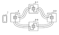
- FIG. 1 is a block diagram showing the configuration of the information processing system according to the first embodiment of the present invention.
- the information processing system shown in FIG. 1 includes a user terminal 1 used by a user, a basic core 2, and a large number of functional modules 3-1 to 3-n (n is an integer of 1 or more).
- n is an integer of 1 or more.
- the number of user terminals 1 and the basic core 2 is not limited to this. Is fine.
- the number n of the functional modules 3-1 to 3-n connected to the basic core 2 is not particularly limited.
- the user terminal 1 communicates with the basic core 2 by various methods, for example, NFC (registered trademark) (Near Field Communication), Bluetooth (registered trademark), and the like.
- NFC registered trademark
- Bluetooth registered trademark
- functional module 3 when it is not necessary to individually distinguish the functional modules 3-1 to 3-n, these are collectively referred to as “functional module 3”.
- FIG. 1 illustrates a daisy-chain type as an example of a connection mode between the basic core 2 and the functional module 3.
- the basic core 2 serves as one end, one functional module 3-1 is connected to the one end, and the functional module 3-1 is further connected to the functional module 3-1. Further, another function module 3 (not shown) is connected to the function module 3-2.
- the basic core 2 is a hardware device that is used by being connected to one or more functional modules 3, and is paired with the user terminal 1 through short-range wireless communication (for example, communication conforming to the NFC (registered trademark) standard). Do the ring.
- short-range wireless communication for example, communication conforming to the NFC (registered trademark) standard.
- the user terminal 1 is connected to the basic core 2-K and the basic core 2-K by performing pairing with a predetermined basic core 2-K (K is an arbitrary integer value from 1 to m). It recognizes L (L is an arbitrary integer) functional modules 3-K1 to 3-KL. That is, the target connected to the basic core 2-K may be a serial connection of L functional modules 3. The user terminal 1 can recognize these L function modules 3 individually.
- the functional module 3 is a hardware device including, for example, various sensors such as a temperature sensor, operating devices such as push buttons, driving devices such as a motor, and the like.
- the pairing between the user terminal 1 and the basic core 2-K will be described.
- the term “pairing” refers to causing the user terminal 1 to recognize the type, connection state, and the like of the basic core 2-K and the functional modules 3 connected thereto using short-range wireless communication.
- the user terminal 1 recognizes the type of the functional module 3 and the connection status, the H parts corresponding to the connected functional module 3 are displayed on the program creation screen.
- the user terminal 1 is configured by a tablet terminal or the like.
- FIG. 2 is a diagram illustrating an example of a configuration in a state where the basic core and the functional module according to the first embodiment of the present invention are connected.
- FIG. 2 illustrates the basic core 2-E, the function module 3-E1, the function module 3-E2, and the battery unit PP.
- the basic core 2-E includes a battery unit BU, serial ports SP1 and SP2, and a short-range wireless communication unit BT.
- the battery unit BU is, for example, a stabilized DC power supply, and supplies electric power to the basic core 2-E, the function module 3-E1, and the function module 3-E2 with current.
- the serial ports SP1 and SP2 are connection ports (connection connectors) for connecting the basic core 2-E to other hardware or the like.
- the basic core 2-E is provided with serial ports SP1 and SP2, and the functional module 3-E1 is provided with a serial port PS1.
- the basic core 2-E and the function module 3-E1 are connected via the two serial ports SP1 and PS1.
- the function module 3-E1 has a serial port PS2, and the function module 3-E2 has a serial port PS3.
- the function module 3-E1 and the function module 3-E2 have the two serial ports PS2, It is connected via PS3.
- the serial module SP2 of the basic core 2-E may be connected to the functional module 3 located at the end connected in series from the serial port SP1, and a plurality of modules may be connected in a loop via the serial port.
- the short-range wireless communication unit BT includes an IC card or the like for performing short-range wireless communication with other hardware or the like by a method according to a predetermined standard (for example, Bluetooth (registered trademark)).
- the user terminal 1 (not shown in FIG. 2) and the basic core 2-E including the short-range wireless communication unit BT are in short-range by a method according to Bluetooth (registered trademark). Perform wireless communication. Specifically, for example, the execution result (command or the like) of the program created in the user terminal 1 is also transmitted to the basic core 2-E.
- Bluetooth registered trademark
- the basic core 2-E acquires the execution result (command or the like) of the program transmitted from the user terminal 1, and further superimposes the result on the current signal (for power supply) as transmission information. Then, of the function modules 3-E1 and 3-E2, the command is transmitted to the target function module 3 such as a command.
- the function module 3-E1 includes a tire T, and the function module 3-E2 includes a buzzer.
- the functional modules 3-E1 and 3-E2 acquire only the execution result (command or the like) of the program for the own device from the transmission information transmitted from the basic core 2-E.
- the functional module 3-E1 in the example of FIG. 2 drives the tire T according to a command for driving the tire among the execution results (commands and the like) of the program created in the user terminal 1.
- the function module 3-E2 sounds the buzzer according to a command or the like for sounding the buzzer among the execution results (commands and the like) of the program created in the user terminal 1.
- the battery unit PP is connected to the functional module 3-E1.
- the battery unit PP supplies power to the function module 3-E1 as an external power supply, and also supplies power to the function module 3-E2 connected to the function module 3-E1.
- the battery unit PP is not an essential component if the basic core 2 can supply necessary power to the function module 3-E1 and the like.
- the program creation process refers to a process for creating a program for causing one or more function modules 3 connected to the basic core 2 to function.
- a two-wire constant current communication circuit is formed.
- the two-wire constant current communication circuit superimposes a signal current on a power supply constant current, thereby omitting wiring dedicated to communication and connecting only with two wires used for power supply to perform current communication.
- This method has a smaller number of wires compared to a case where a power supply line and a communication line are separately wired, and can reduce the thickness of a cable when the power supply line and the communication line are combined into a single line. Fewer connectors are required.
- the current-type communication method does not complicate the circuit and does not increase the cost and the board size even when stable communication over a long distance is realized. That is, according to this method, an assembly block capable of performing stable data communication with a simple configuration can be realized.
- the two-wire constant current communication circuit has a problem that power supply efficiency is poor.
- the wiring in the connection mode between the basic core 2 and the functional module 3, the wiring does not seem to form a closed loop, but the wiring is folded back at the basic core 2 or the functional module 3 located at the end. For this reason, the configuration is electrically closed loop wiring.
- the functional modules 3 since the functional modules 3 are electrically connected in a row, the current flowing through all the functional modules 3 is the same. For this reason, it is necessary to design a system of the basic core 2 and the functional module 3 according to the functional module 3 (for example, the functional module 3-1) which uses the most current.
- the functional module 3 that does not use the current converts the unused current into heat, and the power supply efficiency deteriorates. Therefore, there is a demand for improving the power supply efficiency, that is, a demand for reducing the power consumption of the functional module 3.
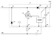
- FIG. 3 is a circuit diagram showing an example of a circuit connected to the two-wire type constant current network shown in FIG. 1, for example, a circuit provided in one predetermined functional module.
- the circuit in FIG. 3 is connected to a two-wire constant current network using a constant current source (not shown) provided in the core module 2.
- 3 is provided in the function module 3.
- the input circuit positive terminal VP and the input circuit negative terminal VM are two-wire connection terminals, and are connected to the constant current source provided in the core module 2.
- the connection is a broad concept including not only a direct connection but also a connection via another element (for example, another function module 3).
- the circuit in FIG. 3 is configured to include a circuit section K having terminals K1 to K4, a current measuring resistor R1, and a capacitor C1.
- the terminal K1 is connected to the input circuit positive terminal VP
- the terminal K3 is connected to one end of the current measuring resistor R1.
- the other end of the current measuring resistor R1 is connected to the input circuit negative terminal VM and one end of the capacitor C1, and the other end of the capacitor C1 is connected to the control unit CT in the circuit unit K.
- a load (not shown) is connected to the terminal K2 of the potential Vcc and the terminal K4.
- the circuit section K has a constant voltage diode D1, a field effect transistor Q1, a Schottky barrier diode D2, a capacitor C2, and a control section CT.
- a constant voltage diode D1, a field effect transistor Q1, a Schottky barrier diode D2, and a series connection of a capacitor C2 are connected in parallel between the terminals K1 and K4.
- An end K2 is provided as a connection end between the Schottky barrier diode D2 and the capacitor C2, and the end K3 and the end K4 are connected at the same potential.
- the control unit CT has an output connected to the gate GT of the field-effect transistor Q1, and an input connected to the terminal K2 of the potential Vcc.
- the control unit CT is also connected to the capacitor C1 as described above and to the terminal K4 (terminal K3).
- the source SC of the field effect transistor Q1 is connected to the terminal K3, and the drain DR of the field effect transistor Q1 is connected to the terminal K1.
- control unit CT switches the state of field effect transistor Q1 as a switching element from one of the ON state and the OFF state to the other according to the value of input potential Vcc. That is, in the circuit of FIG. 3 in a standby state where the load is not operated, when the potential Vcc is higher than the specified voltage, the control unit CT controls the field-effect transistor Q1 to be turned on. As a result, the resistance value between the drain DR and the source SC becomes substantially zero, the circuit K is short-circuited, and the constant-voltage diode D1 does not conduct. Thereby, heat generation from the constant voltage diode D1 is avoided, and the power consumption of the functional module 3 including the circuit of FIG. 3 is greatly reduced.
- the control unit CT controls the field-effect transistor Q1 to be turned off.
- the drain DR and the source SC are substantially insulated from each other, and a constant current is externally supplied to the constant voltage diode D1 to obtain a sufficient voltage required for operating the load. Therefore, the power consumption in this case is equivalent to the conventional case without using the circuit of FIG.
- the power required for the load is sufficiently supplied from the outside in the operating state, while the power consumption is largely suppressed in the standby state.
- the field-effect transistor Q1 has a lower on-resistance, the power-saving effect is exhibited.
- a silicon N-channel MOS field effect transistor can be employed as a specific example of such a field effect transistor for a load switch.
- FIG. 6 is a diagram illustrating an example of a communication waveform when transmitting information for communication from the functional module 3-1 to the core module 2.
- the core module 2, the function module 3-1 and the function module 3-2 form a closed loop and are wired in series.
- the horizontal axis represents time
- the vertical axis represents the voltage between the input circuit positive terminal VP and the input circuit negative terminal VM applied in the functional module 3-1.
- the waveform of the voltage applied in the function module 3-1 is shown in the upper part of FIG. 6 as a communication waveform.
- the horizontal axis indicates time
- the vertical axis indicates the voltage between the input circuit positive terminal VP and the input circuit negative terminal VM applied in the functional module 3-2.
- the function module 3-2 is a function module 3 that does not take any other countermeasures to be described later.
- the function module 3-2 is used.
- the waveform of the voltage applied at -2 is shown in the lower part of FIG.
- the horizontal axes in the upper and lower figures correspond to each time in the upper and lower directions, and the voltages at the same timing can be compared in the upper and lower directions.
- the core module 2, the function module 3-1 and the function module 3-2 are connected in series in a closed loop. Therefore, the actual current between the input circuit positive terminal VP and the input circuit negative terminal VM of each module becomes the same, and the voltage shown in the upper part of FIG. 6 and the voltage shown in the lower part of FIG. The added voltage is applied to the core module 2.
- the information for communication is information composed of a combination of “1” or “0” bits.
- This communication information is transmitted from the functional module 3 to the core module 2 as a pulse waveform signal shown in FIG. 6 having a high-level voltage indicating “0” and a low-level voltage indicating “1”.
- the width of the pulse corresponding to the information for communication is about 50 microseconds.
- the voltage is about 50 microseconds at a low level, about 100 microseconds of one pulse together with about 50 microseconds of the high-level part of an arbitrary length before and after the voltage is about 50 microseconds. It can be said that it is one cycle. That is, the frequency of the communication waveform (pulse waveform) shown in the upper part of FIG. 6 is about 10 KHz.
- the signal of the communication waveform (pulse waveform) shown in the upper part of FIG. the signal of the communication waveform (pulse waveform) shown in the upper part of FIG.
- the switching of the state of the field effect transistor Q1 occurs continuously.
- the switching of the state of the field effect transistor Q1 irrelevant to the communication from the functional module 3 to the core module 2 may occur continuously at a frequency of about 10 KHz as shown in the lower part of FIG.
- the communication waveform (pulse waveform) shown in the upper part of FIG. 6 is superimposed on the voltage waveform between the input circuit positive terminal VP and the input circuit negative terminal VM due to the continuous switching of the state of the field effect transistor Q1. It becomes the same as the voltage waveform in the case.
- the core module 2 which is the transmission destination of the communication information is confused with the pulse wave of the communication information. Easy noise is generated in the function module 3-2.
- FIG. 7 is a diagram illustrating an example of a waveform generated as the state of the switch unit is continuously switched by the two-wire constant current communication circuit according to the first embodiment of the present invention.
- the core module 2, the functional module 3-1 and the functional module 3-2 form a closed loop and are wired in series.
- the upper part of FIG. 7 is the same as the upper part of FIG. That is, in the upper part of FIG.
- the horizontal axis indicates time
- the vertical axis indicates the voltage between the input circuit positive terminal VP and the input circuit negative terminal VM applied in the functional module 3-1.
- the waveform of the voltage applied in the functional module 3-1 is shown as the communication waveform in the upper part of FIG.
- the horizontal axis represents time
- the vertical axis represents the voltage between the input circuit positive terminal VP and the input circuit negative terminal VM applied in the functional module 3-2.
- the horizontal axes of the upper and lower figures correspond to the upper and lower times, and the voltages at the same timing can be compared in the upper and lower directions.
- FIG. 6 the horizontal axes of the upper and lower figures correspond to the upper and lower times, and the voltages at the same timing can be compared in the upper and lower directions.
- FIG. 6 the horizontal axes of the upper and lower figures correspond to the upper and lower times, and the voltages at the same timing can be compared in the upper and lower directions.
- FIG. 6 the horizontal axes of the upper and lower
- the core module 2, the function module 3-1 and the function module 3-2 are wired in series in a closed loop. Therefore, similarly to FIG. 6, the actual current between the input circuit positive terminal VP and the input circuit negative terminal VM of each module becomes the same, and the voltage shown in the upper part of FIG. The added voltage is applied to the core module 2.
- the voltage does not continue at the high level during the time when the voltage becomes the high level.
- the high level and the low level are repeated at a high frequency of about 200 KHz, and a pulse having a high voltage with respect to the width on the time axis, that is, a thin pulse is continuously output. It is shown.
- the functional module 3-2 if the voltage between the input circuit positive terminal VP and the input circuit negative terminal VM makes such a change, for example, a low-pass filter that allows only a signal having a frequency of 100 KHz or less to pass is used as the noise removing unit.
- a low-pass filter that allows only a signal having a frequency of 100 KHz or less to pass is used as the noise removing unit.
- the communication waveform (pulse waveform) shown in the upper part of FIG. 7 having a frequency of about 10 KHz passes through the low-pass filter. Therefore, even if the narrow pulse shown in the lower part of FIG. 7 and the communication waveform (pulse waveform) shown in the upper part of FIG. 7 are mixed, only the communication waveform (pulse waveform) shown in the upper part of FIG. 7 can be extracted. .
- the supply of the high-level voltage is divided into a number of narrow pulses shown in the lower part of FIG. These can be cut off with a low-pass filter. This eliminates adverse effects on communication with the core module 2 and improves the reliability of the communication, so that the core module 2 can reliably control the functional module 3 based on the communication.
- the high-level voltage is generated by the control unit CT controlling the field-effect transistor Q1 to be turned off in order to recover the potential Vcc lower than the specified voltage. Therefore, as described above, if the voltage is not maintained at the high level, the time required to recover the potential Vcc will be prolonged.
- the control unit CT may determine the duty ratio for the narrow pulse shown in the lower part of FIG. 7 based on the electric power required to operate the load. That is, if the power required to operate the load is large, it is determined that the time occupied by the high-level voltage in one cycle is lengthened and the time occupied by the low-level voltage is shortened. Conversely, if the power required to operate the load is small, it is determined that the time occupied by the high-level voltage in one cycle is shortened and the time occupied by the low-level voltage is increased. Then, the control unit CT controls the switching of the state of the field-effect transistor Q1 in accordance with the timing at which the determined duty ratio is applied to a frequency of, for example, about 200 KHz.
- the duty ratio is determined to be 0.4 by the control unit CT and applied to the frequency of 200 KHz
- the time occupied by the high-level voltage in 2 microseconds in one cycle is 2 microseconds.
- Seconds, and the time occupied by the low-level voltage is 3 microseconds.
- the supply of the high-level voltage is divided into a large number of narrow pulses shown in the lower part of FIG.
- the second embodiment in which the state of the field effect transistor Q1 is not switched as much as possible may be adopted.
- the system configuration of the second embodiment is the same as the system configuration of the first embodiment of FIG. That is, the information processing system of the second embodiment also includes the user terminal 1 used by the user, the core module 2, and the many function modules 3.
- the configuration of the second embodiment in a state where the core module 2 and the functional module 3 are connected is the same as that of the first embodiment shown in FIG. 2, and the description thereof will be omitted here.
- FIG. 8 is a circuit diagram illustrating a circuit connected to the two-wire constant current communication network according to the second embodiment of the present invention, for example, a circuit provided in one predetermined functional module.
- the circuit of FIG. 8 is connected to a two-wire constant current network using a constant current source (not shown) provided in the core module 2.
- the circuits shown in FIG. 8 are provided in the function modules 3 respectively.
- the input circuit positive terminal VP and the input circuit negative terminal VM are two-wire connection terminals, and are connected to a constant current source provided in the core module 2.
- the circuit in FIG. 8 is configured to include a circuit section L having terminals L1 to L4, a current measuring resistor R1, and a capacitor C1.
- the terminal L1 is connected to the input circuit positive terminal VP
- the terminal L3 is connected to one end of the current measuring resistor R1.
- the other end of the current measuring resistor R1 is connected to the input circuit negative terminal VM and one end of the capacitor C1, and the other end of the capacitor C1 is connected to the negative terminal of the comparator CM1 in the circuit section L, the negative terminal of the comparator CM2, and the current. It is connected to one end of the level comparison resistor R2.
- a load (not shown) is connected to the terminal L2 of the potential Vcc and the terminal L4.
- the circuit unit L includes a constant voltage diode D1, a field effect transistor Q1, a Schottky barrier diode D2, a capacitor C2, a control unit CT, a reference voltage circuit VR, a current level comparison resistor R2, a comparator CM1, , A comparator CM2.
- a constant voltage diode D1, a field effect transistor Q1, a Schottky barrier diode D2 and a capacitor C2 connected in series are connected in parallel.
- An end L2 is provided as a connection end between the Schottky barrier diode D2 and the capacitor C2, and the end L3 and the end L4 are connected at the same potential.
- a reference voltage circuit VR is also connected to the terminal L2.
- the other three terminals of the reference voltage circuit VR are connected to the current level comparison resistor R2, the positive terminal of the comparator CM1, and the positive terminal of the comparator CM2, respectively.
- the output terminal CO1 of the comparator CM1 is connected to the RX terminal of the control unit CT.
- the output terminal CO2 of the comparator CM2 is connected to the INT terminal of the control unit CT.
- the control unit CT has its output from the Drv terminal connected to the gate GT of the field effect transistor Q1, and its input connected to the terminal L2 of the potential Vcc. As described above, the control unit CT has the RX terminal connected to the output terminal CO1 of the comparator CM1, the INT terminal connected to the output terminal CO2 of the comparator CM2, and the terminal L4 (terminal L3).
- the source SC of the field effect transistor Q1 is connected to the terminal L3, and the drain DR of the field effect transistor Q1 is connected to the terminal L1.
- the constant voltage diode D1, the field effect transistor Q1, the Schottky barrier diode D2, and the capacitor C2 are the same as those in the first embodiment, and thus description thereof will be omitted.
- the input of the reference voltage circuit VR is connected to the terminal L2 of the potential Vcc, and the three terminals on the output side are connected to the current level comparison resistor R2, the positive terminal of the comparator CM1, and the positive terminal of the comparator CM2.
- the other end of the current level comparison resistor R2 is connected to the capacitor C1, the negative terminal of the comparator CM1, and the negative terminal of the comparator CM2.
- the comparator CM1 has a positive terminal connected to one end of the current level comparison resistor R2, a negative terminal connected to one end on the input side of the reference voltage circuit VR, the capacitor C1, and a negative terminal of the comparator CM2.
- the terminal CO1 is connected to the RX terminal of the control unit CT.
- the comparator CM2 has a positive terminal connected to the current level comparison resistor R2, a negative terminal connected to one end on the input side of the reference voltage circuit VR, the capacitor C1, and a negative terminal of the comparator CM2, and an output terminal CO2. Are connected to the INT terminal of the control unit CT.
- the reference voltage circuit VR supplies a voltage serving as a reference for comparing current levels to the current level comparison resistor R2 and the comparators CM1 and CM2. That is, the reference voltage circuit VR supplies the comparator CM1 with a reference voltage for comparing the current level with the first threshold value, and generates a voltage generated across the current measuring resistor R1 according to the current level. Allows comparison with
- the first threshold is a threshold for the current level, and is a threshold for obtaining bit information of 1 or 0 from the current.
- the bit information takes a value of 1
- the bit information takes a value of 0.
- the reference voltage circuit VR supplies the comparator CM2 with a reference voltage for comparing the current level with the second threshold value, and generates a voltage generated across the current measuring resistor R1 according to the current level. Allows comparison with That is, the second threshold value is a threshold value for detecting a signal for notifying the start of communication from the current.
- the reference voltage circuit VR outputs 1.5 V to the current level comparison resistor R2 and the reference voltage of the comparator CM1.
- a voltage of 1.6 V is supplied to the positive electrode, and a voltage of 1.7 V is supplied to the positive electrode of the comparator CM2.
- the comparator CM1 compares the level of the current from the capacitor C1 and the first threshold value with the corresponding voltages. If the level of the current from the capacitor C1 exceeds the first threshold value, the comparator CM1 controls the output terminal CO1. A signal of 0 is output to the RX terminal of the unit CT. The signal means a bit value of 0. The comparator CM1 compares the level of the current from the capacitor C1 and the first threshold value with the corresponding voltages, and if the level of the current from the capacitor C1 does not exceed the first threshold value, the output terminal CO1 From the control unit CT to the RX terminal. The signal has a bit value of 1. That is, the comparator CM1 is a comparator for decoding communication information from the current.
- the control unit CT may recognize that the transmission of information has ended, for example, when the state continues for a predetermined time after the input of the signal of 0 to the RX terminal is stopped.
- the comparator CM2 compares the level of the current from the capacitor C1 with the second threshold. If the level of the current from the capacitor C1 exceeds the second threshold, the comparator CM2 connects the output terminal CO2 to the INT terminal of the control unit CT. , 0 signals. This signal means that communication is started.
- the comparator CM2 compares the level of the current from the capacitor C1 with the second threshold value. If the level of the current from the capacitor C1 does not exceed the second threshold value, the comparator CM2 outputs the signal INT of the control unit CT from the output terminal CO2. Output 1 signal to the terminal. This signal has no particular meaning. That is, the comparator CM2 is a comparator for detecting a signal notifying the start of transmission of communication information from the core module 2 to the functional module 3 from the current based on the corresponding voltage.
- the control unit CT changes the state of the field-effect transistor Q1 as a switching element according to the value of the input potential Vcc, the 1 or 0 signal from the comparator CM1, and the 1 or 0 signal from the comparator CM2. Is switched from one of the ON state and the OFF state to the other. That is, as in the first embodiment, in the circuit of FIG. 8 in a standby state in which the load is not operated, when the potential Vcc is higher than the specified voltage, the control unit CT turns on the field effect transistor Q1. To control. As a result, the resistance between the drain DR and the source SC becomes substantially zero, causing the circuit L to be short-circuited, and the constant voltage diode D1 does not conduct. As a result, heat generation from the constant voltage diode D1 is avoided, and the power consumption of the functional module 3 including the circuit of FIG. 8 is greatly reduced.
- the control unit CT turns off the field effect transistor Q1.
- the drain DR and the source SC are substantially insulated from each other, and a constant current is externally supplied to the constant voltage diode D1 to obtain a sufficient voltage required for operating the load. Therefore, the power consumption in this case is equivalent to the conventional case without using the circuit of FIG.
- control unit CT recognizes at least a part of the communication information transmitted from the core module 2 based on the signal of 1 or 0 from the comparator CM1.
- the control unit CT may be able to recognize, from the communication information, information that can specify the functional module 3 that is the destination, information on the bit length of the communication information, and the like. Thereby, the control unit CT can recognize whether the information for communication has been transmitted to the function module 3. Further, thereby, the control unit CT can recognize that the communication has been completed when the transmission of the communication information for the bit length is performed.
- the bit length of the communication information may be a fixed length. In this case, even if the information of the bit length of the communication information is not included, it is possible to recognize that the communication has been completed when the transmission of the fixed length is performed.
- the sleep state means that the control by the control unit CT to restore the potential Vcc to the specified voltage is made to sleep (sleep) until communication from the core module 2 to the self-function module 3 or another function module 3 is started.
- This is a state in which the switching between the ON state and the OFF state of the field effect transistor Q1 does not occur. That is, even when the functional module 3 is in the standby state in which the load is not operated, the potential Vcc gradually decreases, and when the functional module 3 reaches a state lower than the specified voltage, in the circuit of FIG. Q1 was controlled to be turned off.
- the control unit CT controls the field-effect transistor Q1 to repeat the ON state and the OFF state, and each time, the communication waveform (pulse) shown in FIG. A waveform similar to (waveform) is generated, which causes a malfunction.
- the control unit CT does not immediately turn off the field-effect transistor Q1 and switches the field effect transistor Q1 from the core module 2 to the self-function module 3 or another function module 3. Even if the power supply is turned off after the communication starts, the power supply to the load can be completed in time, so that the function module 3 is sufficient.
- control by the control unit CT to restore the potential Vcc to the specified voltage is set to sleep (sleep) until communication from the core module 2 to the self-function module 3 or another function module 3 is started, and the electric field effect during the sleep is performed. It is conceivable that the switching of the transistor Q1 between the on state and the off state does not occur. Further, until the communication between the core module 2 and the self-function module 3 or another function module 3 ends, the field-effect transistor Q1 remains in the off state, and after the communication ends, switching to the on state is performed. It is possible to make it possible.
- the control unit CT switches the field-effect transistor Q1 from the on-state to the off-state when the comparator module CM2 detects a signal notifying the start of transmission of communication information from the core module 2 in the functional module 3, It is possible to switch. Therefore, in this case, when the information for communication is transmitted from another functional module 3 to the core module 2, the amount of the voltage change due to the switching of the state of the field effect transistor Q 1, which becomes a noise, is determined by the circuit of FIG. Is equivalent to Further, the control unit CT, when recognizing that the transmission of the information to another functional module 3 has been completed or recognizing that the detection of the transmission of the information by the comparator CM1 has been completed, in the functional module 3, causes the field effect transistor Q1 to operate.
- the control unit CT causes the control by the control unit CT to restore the potential Vcc to the specified voltage, until the communication from the core module 2 to the own function module 3 or another function module 3 is started (sleeps). . Further, until the communication between the core module 2 and the self-function module 3 or another function module 3 ends, the switching of the state of the field-effect transistor Q1 is limited to be kept off, and after the communication ends. , Enabling switching to the on state. In this way, when communication information is transmitted from another functional module 3 to the core module 2, the occurrence of a voltage change due to the switching of the state of the field effect transistor Q1, which is a noise, is avoided during communication. You. This eliminates adverse effects on the communication to the core module 2 and improves the reliability of the communication, so that the core module 2 reliably controls another functional module 3 including the circuit of FIG. 8 based on the communication. Can be done.
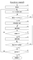
- FIG. 9 is a flowchart illustrating a flow of a low power consumption mode control process performed by the two-wire constant current communication circuit according to the second embodiment of the present invention.
- the control unit CT performs an initialization process.
- the initialization process is, for example, a process of initial recognition of each core module 2 and many function modules 3 necessary for communication between the core module 2 and many function modules 3.
- the control unit CT shifts to a sleep state. That is, the control by the control unit CT to restore the potential Vcc to the specified voltage is made to sleep.
- the control unit CT determines whether the level of the current flowing between the input circuit positive terminal VP and the input circuit negative terminal VM is equal to or higher than the second threshold.
- step S3 If the level of the current flowing between the input circuit positive terminal VP and the input circuit negative terminal VM is less than the second threshold, it is determined as NO in step S3, and the determination processing of step S3 is repeated. If a current equal to or more than the second threshold value is detected while the determination process of step S3 is repeated, it is determined that the answer is YES in the next step S3, and the process proceeds to step S4.
- step S4 the control unit CT stops the sleep state and shifts to a state of activating the recovery of the potential Vcc to the specified voltage. Thereby, the communication process by the control unit CT can be executed.
- step S5 the control unit CT performs a communication process.
- step S5 the control unit CT reads a signal from the comparator CM1 and extracts at least a destination of information. Note that the length of the communication may be extracted.
- step S6 the control unit CT determines whether the destination of the information is the self-function module 3. If the destination of the information is different from the own module, it is determined as NO in step S6, and the process proceeds to step S8.
- step S6 if the destination of the information is the own module, it is determined to be YES, and the process proceeds to step S7.
- step S7 the control unit CT activates the load based on the result of the communication processing in step S5, that is, based on the control of the core module 2.
- step S8 the control unit CT determines whether the communication from the core module 2 to the own function module 3 or another function module 3 has been completed. If the communication is in progress, NO is determined in step S8, and the process returns to the communication process of step S5, and the subsequent processes are repeated. In step S8, if the communication ends, the control unit CT determines that the answer is YES, and the process proceeds to step S9. In step S9, the control unit CT determines whether an instruction to end the low power consumption mode control process has been issued.
- the processing termination instruction is not particularly limited, but in the present embodiment, the processing termination instruction from the core module 2 is employed.
- step S9 unless an instruction to end the process is issued from the core module 2, it is determined as NO in step S9, the process returns to step S2, and the subsequent processes are repeated. On the other hand, when an instruction to end the process is issued from the core module 2, YES is determined in step S9, and the low power consumption mode control process ends.
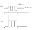
- FIG. 10 is a diagram illustrating an example of a waveform obtained by the two-wire constant current communication circuit according to the second embodiment of the present invention.
- the horizontal axis indicates time
- the vertical axis indicates the current between the input circuit positive terminal VP and the input circuit negative terminal VM.
- the horizontal axis represents time
- the vertical axis represents the voltage between the input circuit positive terminal VP and the input circuit negative terminal VM.
- FIG. 10 shows a waveform of a voltage applied to the functional module 3 when information for communication is transmitted from the functional module 3 to the core module 2.
- the horizontal axes of the upper and lower figures are assumed to correspond to the respective times in the upper and lower directions, and the current and the voltage at the same timing can be compared in the upper and lower directions.
- a pulse current having a level exceeding the second current level (second threshold) is transmitted from the core module 2 as a signal notifying the start of transmission of communication information.
- second threshold the second current level
- the control unit CT performs a communication process.
- a pulse current having a level exceeding the first current level (first threshold) is intermittently transmitted from the core module 2 as bit information indicating “0” in the communication information.
- the comparator CM1 extracts the pulse current having a level exceeding the first threshold as information of 0 and the pulse current having a level not exceeding the first threshold as 1 as information.
- the control unit CT has recognized that the destination of the information for communication from the core module 2 was the self-function module 3. That is, it is determined to be YES at the timing when step S6 in FIG. 9 is executed, and the process proceeds to step S7.
- the control unit CT transmits the information for communication to the core module 2 and activates the load according to the information for communication from the core module 2.
- a voltage is applied between the input circuit positive terminal VP and the input circuit negative terminal VM.
- step S8 in FIG. 10 determines whether the communication has ended. It is assumed that the communication is continued until time t2, and at the timing when step S8 in FIG. 9 is executed, it is determined to be NO, and the process returns to the communication process of step S5, and the subsequent processes are repeated. Each of the above processes is repeated until time t2.
- step S8 in FIG. 9 communication with the core module 2 ends, and in step S8 in FIG. 9, it is determined to be YES, and the process proceeds to step S9 in FIG.
- step S9 in FIG. 9 the control unit CT determines that there is no instruction to end the low power consumption mode control process, and the process returns to step S2 in FIG. 9. Is repeated.
- the present invention is not limited to the above-described embodiment, and modifications, improvements, and the like within a range that can achieve the object of the present invention are included in the present invention. is there.
- a battery capable of supplying a stable direct current may be employed, and the supplied current is not limited to direct current, and an alternating current may be supplied by employing various means such as an inverter. .
- the electronic device according to the present invention may be provided with power line communication. In this way, power supply and communication can be performed using only two lines. In addition, this makes it possible to form a simple circuit that is strong against noise. That is, the present invention can be applied to an electronic device that can stabilize data communication with a simple configuration.
- the field effect transistor Q1 included in the electronic device according to the present invention may also serve as a switching element provided for power line communication. By doing so, it is possible to reduce the number of components of the power circuit.
- the components for measuring the power supply voltage that constitute the electronic device according to the present invention may also be the components built in the microcomputer provided for the power line communication. By doing so, it is not necessary to separately add a comparator, and the number of components can be reduced.
- the field-effect transistor Q1 is employed.
- any device having a switching function is sufficient, and the present invention is not particularly limited to this.
- the functional module 3 it suffices to provide an element for changing the resistance value. This is because if the resistance value can be changed and the voltage between both ends of the functional module 3 can be suppressed, the power of the functional module 3 can be suppressed.
- the present invention is not limited to this, and a power supply line and a communication line may be separately provided.
- the connection is not limited to the wired connection only, and wireless power supply and communication may be combined.
- the numbers of the basic cores 2 and the functional modules 3 are not particularly limited to the above-described embodiments. That is, the number of the basic cores 2 and the number of the function modules 3 may be the same or different. That is, one functional module 3 may be connected to one basic core 2.
- FIG. 4 illustrates a star type as an example of a connection mode between the basic core 2 and the functional module 3.
- the star type shown in FIG. 4 is a connection mode in which the basic core 2 and two or more functional modules 3 (three functional modules 3-1 to 3-3 in the example of FIG. 4) are connected in a star type. .
- FIG. 5 illustrates a loop type as an example of a connection mode between the basic core 2 and the functional module 3.
- the basic core 2 and one or more functional modules 3 form a loop in a predetermined order (in the example of FIG. 5, the order of the basic core 2 and the functional modules 3-1 to 3-3). Are connected to form a closed loop.
- connection mode is basically the above connection mode. However, if a configuration that electrically forms a closed loop wiring is adopted, an arbitrary connection mode can be adopted by combining the above connection modes.
- a signal transmitted from the basic core 2 to supply power to one or more functional modules 3 is only required to be in a form capable of transmitting power by a current method. You may.
- the two-wire constant current communication network is provided in the set of the core module 2 and the functional module 3.
- the two-wire constant current communication network is not limited to this.
- a two-wire constant current communication network may be used in an arbitrary set made up of a module having a constant current source (master) and another module (slave). May be provided.
- the information for communication is a signal having a high-level voltage indicating “0” and a low-level voltage indicating “1” as a pulse waveform signal illustrated in FIG. Is transmitted to the core module 2 by way of example, but this is an example, and the present invention is not limited to this. That is, the information of 0 or 1 may be a reverse combination of the high-level voltage and the low-level voltage, where the low-level voltage indicates “0” and the high-level voltage indicates “1”. You can show.
- the comparator CM1 extracts the pulse current of the level exceeding the first threshold as information of 1 and the pulse current of the level not exceeding the first threshold as 0, but extracts this as an example. But it is not limited to this. That is, the extracted information of 0 or 1 may be a reverse combination of whether or not the pulse current exceeds the first threshold, and the pulse current that does not exceed the first threshold is the information of the pulse current exceeding the first threshold as 0. The current may be extracted as one.
- the second current level (second threshold) is a current level (threshold) higher than the first current level (first threshold). I can't. That is, the second current level (second threshold) may be the same current level (threshold) as the first current level (first threshold).
- the time during which the high-level voltage is obtained is controlled so that the state of the field-effect transistor Q1 is continuously switched at a high frequency.
- this is an example, and the present invention is not limited to this. Absent.
- the state of the field effect transistor Q1 may be controlled so as to be continuously switched at a high frequency as a configuration in which the time when the voltage at the low level becomes the voltage including the current measuring resistor R1 can be shortcutted.
- the above-described series of processing can be executed by hardware or can be executed by software. That is, it is sufficient that the information processing system has a function capable of executing the above-described series of processing as a whole.
- one functional block may be constituted by hardware alone, may be constituted by software alone, or may be constituted by a combination thereof.
- a program constituting the software is installed in a computer or the like from a network or a recording medium.
- the computer may be a computer embedded in dedicated hardware.
- the computer may be a computer that can execute various functions by installing various programs, for example, a general-purpose smartphone or a personal computer other than a server.
- a recording medium including such a program is not only constituted by a removable medium (not shown) distributed separately from the apparatus main body in order to provide the user with the program, but also a state in which the recording medium is pre-installed in the apparatus main body. And a recording medium provided to the user.
- steps for describing a program recorded on a recording medium are not limited to processing performed in chronological order according to the order, but are not necessarily performed in chronological order, but are performed in parallel or individually. This includes the processing to be executed. Also, in this specification, the term system refers to an entire device including a plurality of devices and a plurality of means.
- the electronic device to which the present invention is applied can take various embodiments having the following configurations. That is, the electronic device to which the present invention is applied (for example, the functional module 3 in FIG. 1) In an electronic device including at least a part of a constant current network connected to a predetermined load, A control unit that controls an applied voltage to the predetermined load based on a state related to the predetermined load (for example, a control unit CT in FIG. 3) An electronic device having the above is sufficient.
- the electronic device includes: A path where at least a part of the voltage applied to the predetermined load is generated when a constant current flows through the constant current network (for example, a path from terminal K1 to terminal K3 via constant voltage diode D1 in FIG. 3).
- a switch unit for example, the field-effect transistor Q1 in FIG. 3 for switching between short-circuiting of the path and cancellation of short-circuiting of the path;
- the control unit controls a voltage applied to the predetermined load by switching a state of the switch unit.
- the electronic device includes: A module (eg, the functional module 3 of FIG. 1) having the predetermined load and the electronic device is included in the constant current network (eg, the circuit K of FIG. 3);
- the constant current network when information for communication is transmitted as a first pulse which repeats a voltage level at a first frequency,
- the control unit for example, the control unit CT in FIG. 3
- the state of the switch unit for example, the field effect transistor Q1 in FIG. 3
- the predetermined load is changed in the form of a second pulse that repeats a voltage level at the second frequency. Is controlled.
- the control unit executes control for determining a duty ratio in the second pulse based on power required for the predetermined load. By doing so, it is possible to supply electric power according to the electric power required for operating the load.
- the electronic device includes: A module having the predetermined load and the electronic device (for example, the functional module 3 of FIG. 1) is included in the constant current network;
- a first detection unit for example, a comparator CM2 in FIG. 8) that detects the start of transmission of the information in the module;
- the control unit for example, the control unit CT in FIG. 8) In the module, When the start of transmission of the information is detected by the first detection unit, The state of the switch unit (for example, the field effect transistor Q1 in FIG. 8) From the short-circuit state of the path, to the release state of the short-circuit of the path, Switch.
- the first detection unit is, for example, the comparator CM2 in FIG. 8, but this is an example, and is not limited to the comparator. That is, any one that can detect the start of transmission of the information for communication transmitted in the constant current network in the module can be adopted. For example, a combination of an A / D converter and a program determiner may be used.
- the electronic device includes: The control unit (for example, the control unit CT in FIG. 8) In the module (for example, the functional module 3 in FIG. 1), When recognizing the end of the transmission of the information, The state of the switch unit (for example, the field effect transistor Q1 in FIG. 8) From the state of release of the short-circuit of the path, to the state of short-circuit of the path, Switch. By doing so, the state of the field effect transistor Q1 is switched after the communication is completed, so that the adverse effect on the communication from the self-function module 3 or another function module 3 to the core module 2 is eliminated. be able to.
- the control unit for example, the control unit CT in FIG. 8
- the state of the switch unit for example, the field effect transistor Q1 in FIG. 8 From the state of release of the short-circuit of the path, to the state of short-circuit of the path, Switch. By doing so, the state of the field effect transistor Q1 is switched after the communication is completed, so that the adverse effect on the communication from the self-function module
- the electronic device includes: A second detection unit that detects the end of transmission of the information in the module,
- the control unit for example, the control unit CT in FIG. 8) In the module (for example, the functional module 3 in FIG. 1),
- the second detection unit for example, the comparator CM1 in FIG. 8
- the state of the switch unit for example, the field effect transistor Q1 in FIG. 3 From the state of release of the short-circuit of the path, to the state of short-circuit of the path, Switch.
- the second detection unit is, for example, the comparator CM1 in FIG. 8, but this is an example, and is not limited to the comparator.
- any one that can detect the end of the transmission of the information for communication transmitted in the constant current network in the module can be adopted.
- a combination of an A / D converter and a program determiner may be used.
- the first detection unit for example, the comparator CM2 in FIG. 8
- the second detection unit may serve as the second detection unit.
- it is not necessary to separately provide a second detection unit for example, the comparator CM1 in FIG. 8.
- the state of the field effect transistor Q1 is switched after the communication is completed, so that the adverse effect on the communication from the self-function module 3 or another function module 3 to the core module 2 is eliminated. be able to.
- the electronic device includes: The control unit (for example, the control unit CT in FIG. 8) In the module (for example, the functional module 3 in FIG. 1), Until the end of transmission of the information is recognized, The state of the switch unit (for example, the field effect transistor Q1 in FIG. 8) Without switching in the state of the release of the short-circuit of the route, When recognizing the end of the transmission of the information, The state of the switch unit (for example, the field effect transistor Q1 in FIG. 8) From the state of release of the short-circuit of the path, to the state of short-circuit of the path, Switch. By doing so, the state of the field effect transistor Q1 is switched after the communication is completed, so that the adverse effect on the communication from the self-function module 3 or another function module 3 to the core module 2 is eliminated. be able to.
- the control unit for example, the control unit CT in FIG. 8
- the state of the switch unit for example, the field effect transistor Q1 in FIG. 8
- the state of the switch unit for example, the field
- the electronic device includes: A second detection unit that detects the end of transmission of the information in the module,
- the control unit for example, the control unit CT in FIG. 8) In the module (for example, the functional module 3 in FIG. 1), Until the end of the transmission of the information is detected by the second detection unit (for example, the comparator CM1 in FIG. 8).
- the state of the switch unit for example, the field effect transistor Q1 in FIG. 8) Without switching in the state of the release of the short-circuit of the route,
- the second detection unit for example, the comparator CM1 in FIG. 8
- the state of the switch unit for example, the field effect transistor Q1 in FIG.
- the second detection unit is, for example, the comparator CM1 in FIG. 8, but this is an example, and is not limited to the comparator. That is, any one that can detect the end of the transmission of the information for communication transmitted in the constant current network in the module can be adopted. For example, a combination of an A / D converter and a program determiner may be used.
- the first detection unit for example, the comparator CM2 in FIG. 8
- the second detection unit may serve as the second detection unit. In this case, it is not necessary to separately provide a second detection unit (for example, the comparator CM1 in FIG. 8). By doing so, the state of the field effect transistor Q1 is switched after the communication is completed, so that the adverse effect on the communication from the self-function module 3 or another function module 3 to the core module 2 is eliminated. be able to.
Abstract
Description
例えば特許文献1に記載された技術によれば、発光状態をフォトダイオードで検出し、フォトダイオードの検出値に応じて定電流回路を制御して発光ダイオードに流れる電流を制御するLED照明装置の提供がなされている。
ところで、本願出願人は、電力線通信を用いて通信すると共に電力の供給を受ける電子機器を開発して、特願2017-156827として特許出願をしている。 2. Description of the Related Art Conventionally, there is a technique for suppressing power supply using a constant current (for example, see Patent Document 1).
For example, according to the technology described in
By the way, the applicant of the present application has developed an electronic device that performs communication using power line communication and receives power supply, and has filed a patent application as Japanese Patent Application No. 2017-156827.
所定負荷に繋がる定電流回路網の少なくとも一部を含む電子機器において、
前記所定負荷に関する状態に基づいて、当該所定負荷に対する印加電圧を制御する制御部
を有する。 In order to achieve the above object, an electronic device of one embodiment of the present invention includes:
In an electronic device including at least a part of a constant current network connected to a predetermined load,
A control unit that controls an applied voltage to the predetermined load based on a state related to the predetermined load.
以下、本発明の実施形態について、図面を用いて説明する。 [First Embodiment]
Hereinafter, embodiments of the present invention will be described with reference to the drawings.
図1に示す情報処理システムは、ユーザにより使用されるユーザ端末1と、ベーシックコア2と、多数の機能モジュール3-1乃至3-n(nは1以上の任意の整数値)とを含む。
なお、ユーザ端末1とベーシックコア2との夫々は、図1の例では説明の便宜上1台のみ図示されているが、特にこれに限定されず、後述するペアリングが可能であれば任意の台数でよい。
また、ベーシックコア2に接続される機能モジュール3-1乃至3-nの台数nは、特に限定されない。図1の例のようにn=2であってもよいし、図4や図5の例のようにn=3であってもよいし、nはその他の整数値であってもよい。 FIG. 1 is a block diagram showing the configuration of the information processing system according to the first embodiment of the present invention.
The information processing system shown in FIG. 1 includes a
Although only one
Further, the number n of the functional modules 3-1 to 3-n connected to the
なお、以下、機能モジュール3-1乃至3-nを個々に区別する必要がない場合、これらをまとめて「機能モジュール3」と呼ぶ。 The
Hereinafter, when it is not necessary to individually distinguish the functional modules 3-1 to 3-n, these are collectively referred to as “
図1に示すディジーチェーン型は、ベーシックコア2が一端となって、当該一端に1台の機能モジュール3-1が接続され、当該機能モジュール3-1に更に機能モジュール3-2が接続され、さらには当該機能モジュール3-2に図示せぬ別の機能モジュール3が接続されてゆく、いわゆる芋づる式の接続態様である。 FIG. 1 illustrates a daisy-chain type as an example of a connection mode between the
In the daisy chain type shown in FIG. 1, the
ベーシックコア2とは、1以上の機能モジュール3と接続して使用するハードウェアデバイスであり、近距離無線通信(例えば、NFC(登録商標)の規格に準拠した通信)でユーザ端末1とのペアリングを行う。 Here, the
The
つまり、ベーシックコア2-Kと接続される対象は、L個の機能モジュール3の直列接続で良い。ユーザ端末1は、これらをL個のそれぞれの機能モジュール3を個別に認識することができる。
機能モジュール3とは、例えば、温度センサ等の各種センサ、プッシュボタン等の操作器具、モーター等の駆動器具等により構成されるハードウェアデバイスである。 The
That is, the target connected to the basic core 2-K may be a serial connection of L
The
本実施形態では、ベーシックコア2-Kに接続された機能モジュール3の動作を少なくとも伴うプログラムの作製に際して、ユーザ端末1とベーシックコア2-Kとについて近距離無線通信を利用したペアリングを行う必要がある。 Here, the pairing between the
In the present embodiment, when creating a program that involves at least the operation of the
なお、ユーザ端末1では、機能モジュール3の種別や接続の状態等を認識すると、接続された機能モジュール3に対応するHパーツがプログラム作製画面に表示される。
ユーザ端末1は、タブレット端末等で構成される。 In short, the term “pairing” refers to causing the
When the
The
図2は、本発明の第1実施形態に係るベーシックコア及び機能モジュールが接続された状態の構成の一例を示す図である。 Next, referring to FIG. 2, the basic core 2-E (E is an arbitrary integer value from 1 to m), the function module 3-E1 and the function module 3-E2 (E1, E2 are 1 to n The details of the connection mode (arbitrary integer value) will be described.
FIG. 2 is a diagram illustrating an example of a configuration in a state where the basic core and the functional module according to the first embodiment of the present invention are connected.
ベーシックコア2-Eには、バッテリーユニットBU、シリアルポートSP1及びSP2並びに近距離無線通信部BTが備えられている。 FIG. 2 illustrates the basic core 2-E, the function module 3-E1, the function module 3-E2, and the battery unit PP.
The basic core 2-E includes a battery unit BU, serial ports SP1 and SP2, and a short-range wireless communication unit BT.
シリアルポートSP1、SP2は、ベーシックコア2-Eと他のハードウェア等とを接続するための接続口(接続コネクタ)である。 The battery unit BU is, for example, a stabilized DC power supply, and supplies electric power to the basic core 2-E, the function module 3-E1, and the function module 3-E2 with current.
The serial ports SP1 and SP2 are connection ports (connection connectors) for connecting the basic core 2-E to other hardware or the like.
そして、ベーシックコア2-Eと機能モジュール3-E1は、この2つのシリアルポートSP1、PS1を介して接続されている。 In the example of FIG. 2, the basic core 2-E is provided with serial ports SP1 and SP2, and the functional module 3-E1 is provided with a serial port PS1.
The basic core 2-E and the function module 3-E1 are connected via the two serial ports SP1 and PS1.
ベーシックコア2-EのシリアルポートSP2には、シリアルポートSP1から直列に接続された終端に位置する機能モジュール3と、そのシリアルポートを介して、複数のモジュールを、ループ状に接続させて良い。
近距離無線通信部BTは、他のハードウェア等と所定の規格(例えば、Bluetooth(登録商標))に従った方式で近距離無線通信を行うためのICカード等が搭載されている。 Further, the function module 3-E1 has a serial port PS2, and the function module 3-E2 has a serial port PS3. The function module 3-E1 and the function module 3-E2 have the two serial ports PS2, It is connected via PS3.
The serial module SP2 of the basic core 2-E may be connected to the
The short-range wireless communication unit BT includes an IC card or the like for performing short-range wireless communication with other hardware or the like by a method according to a predetermined standard (for example, Bluetooth (registered trademark)).
具体的に例えば、ユーザ端末1で作製されたプログラムの実行結果(コマンド等)は、ベーシックコア2-Eにも送信される。 In the example of FIG. 2, the user terminal 1 (not shown in FIG. 2) and the basic core 2-E including the short-range wireless communication unit BT are in short-range by a method according to Bluetooth (registered trademark). Perform wireless communication.
Specifically, for example, the execution result (command or the like) of the program created in the
また、機能モジュール3-E1は、タイヤTを、機能モジュール3-E2は、ブザーを備えている。 More specifically, the basic core 2-E acquires the execution result (command or the like) of the program transmitted from the
The function module 3-E1 includes a tire T, and the function module 3-E2 includes a buzzer.
図2の例の機能モジュール3-E1は、ユーザ端末1で作製されたプログラムの実行結果(コマンド等)のうち、タイヤを駆動させるコマンド等に従って、タイヤTを駆動する。機能モジュール3-E2は、ユーザ端末1で作製されたプログラムの実行結果(コマンド等)のうち、ブザーを鳴動させるコマンド等に従って、ブザーを鳴動させる。 Then, as described above, the functional modules 3-E1 and 3-E2 acquire only the execution result (command or the like) of the program for the own device from the transmission information transmitted from the basic core 2-E.
The functional module 3-E1 in the example of FIG. 2 drives the tire T according to a command for driving the tire among the execution results (commands and the like) of the program created in the
このバッテリーユニットPPは、外部電源として機能モジュール3-E1に電力を供給し、更には機能モジュール3-E1に接続された機能モジュール3-E2等にも電力を供給する。
なお、上述したように、ベーシックコア2から、機能モジュール3-E1等に必要分の電力の供給が可能であるならば、バッテリーユニットPPは必須な構成要素ではない。 Here, in the example of FIG. 2, the battery unit PP is connected to the functional module 3-E1.
The battery unit PP supplies power to the function module 3-E1 as an external power supply, and also supplies power to the function module 3-E2 connected to the function module 3-E1.
Note that, as described above, the battery unit PP is not an essential component if the
ここで、プログラム作製処理とは、ベーシックコア2に接続された機能モジュール3を1以上機能させるためのプログラムを作成するための処理をいう。 Cooperation of various kinds of hardware and various kinds of software of the
Here, the program creation process refers to a process for creating a program for causing one or
2線式定電流通信回路とは、電力供給用定電流に信号電流を重畳することにより、通信専用の配線を省略し、電力供給に用いる2本の配線のみで接続して、電流通信を行う回路をいう。
この方式は、電力供給線と通信線を別個に配線する場合と比較して配線数が少なく、1本に纏める等した場合にケーブルを細くすることができ、配線のとり回しが良く、また、必要になる接続コネクタも少なく済む。
また、電流型通信方式は、電圧型通信方式とは異なり、長距離での安定した通信を実現する場合であっても回路が複雑化せず、コストや基板サイズが肥大化しない。つまり、この方式であれば、簡単な構成で安定してデータ通信ができる組み立てブロックを実現することができる。 Here, in the
The two-wire constant current communication circuit superimposes a signal current on a power supply constant current, thereby omitting wiring dedicated to communication and connecting only with two wires used for power supply to perform current communication. Refers to a circuit.
This method has a smaller number of wires compared to a case where a power supply line and a communication line are separately wired, and can reduce the thickness of a cable when the power supply line and the communication line are combined into a single line. Fewer connectors are required.
Also, unlike the voltage-type communication method, the current-type communication method does not complicate the circuit and does not increase the cost and the board size even when stable communication over a long distance is realized. That is, according to this method, an assembly block capable of performing stable data communication with a simple configuration can be realized.
図1に示すように、ベーシックコア2と機能モジュール3の接続態様では、外見上配線が閉ループを構成していないが、端部に位置するベーシックコア2又は機能モジュール3において配線が折り返されているため、電気的には閉ループ配線となる構成をとっている。かかる配線構成において、機能モジュール3同士は電気的に数珠繋ぎのため、全ての機能モジュール3に流す電流が同一である。このため、電流を最も多く用いる機能モジュール3(例えば機能モジュール3-1)にあわせて、ベーシックコア2と機能モジュール3とのシステムを設計する必要がある。
このため、電流を使わない機能モジュール3(例えば機能モジュール3-2)は、使わない電流を熱に変えてしまい、電源効率が悪くなる。
したがって、電源効率を上げるという要望、即ち、機能モジュール3の省電力化を図るという要望が存在する。 However, the two-wire constant current communication circuit has a problem that power supply efficiency is poor.
As shown in FIG. 1, in the connection mode between the
For this reason, the
Therefore, there is a demand for improving the power supply efficiency, that is, a demand for reducing the power consumption of the
図3は、図1に示す2線式定電流回路網に接続される回路であって、例えば所定の1の機能モジュールに設けられる回路の一例を示す回路図である。
図3の回路は、コアモジュール2に設けられる図示せぬ定電流源を用いる二線式定電流回路網に接続されている。この図3の回路は、機能モジュール3に設けている。 In order to meet such a demand, the functional module of the present embodiment is provided with a circuit as shown in FIG.
FIG. 3 is a circuit diagram showing an example of a circuit connected to the two-wire type constant current network shown in FIG. 1, for example, a circuit provided in one predetermined functional module.
The circuit in FIG. 3 is connected to a two-wire constant current network using a constant current source (not shown) provided in the
回路部Kのうち、端K1は入力回路正極端子VPに接続されており、端K3は電流計測用抵抗R1の一端に接続されている。電流計測用抵抗R1の他端は、入力回路負極端子VM及びコンデンサC1の一端に接続されており、コンデンサC1の他端は回路部K内の制御部CTに接続されている。
回路部Kのうち、電位Vccの端K2と、端K4とには図示せぬ負荷が接続されている。 The circuit in FIG. 3 is configured to include a circuit section K having terminals K1 to K4, a current measuring resistor R1, and a capacitor C1.
In the circuit section K, the terminal K1 is connected to the input circuit positive terminal VP, and the terminal K3 is connected to one end of the current measuring resistor R1. The other end of the current measuring resistor R1 is connected to the input circuit negative terminal VM and one end of the capacitor C1, and the other end of the capacitor C1 is connected to the control unit CT in the circuit unit K.
In the circuit section K, a load (not shown) is connected to the terminal K2 of the potential Vcc and the terminal K4.
回路部Kにおいて、端K1と端K4との間において、定電圧ダイオードD1と、電界効果トランジスタQ1と、ショットキーバリアダイオードD2及びコンデンサC2の直列接続とが並列に接続されている。ショットキーバリアダイオードD2及びコンデンサC2の接続端として、端K2が設けられており、端K3と端K4は同電位で接続されている。 The circuit section K has a constant voltage diode D1, a field effect transistor Q1, a Schottky barrier diode D2, a capacitor C2, and a control section CT.
In the circuit section K, a constant voltage diode D1, a field effect transistor Q1, a Schottky barrier diode D2, and a series connection of a capacitor C2 are connected in parallel between the terminals K1 and K4. An end K2 is provided as a connection end between the Schottky barrier diode D2 and the capacitor C2, and the end K3 and the end K4 are connected at the same potential.
制御部CTは、上述の如く、入力される電位Vccの値に応じて、スイッチング素子としての電界効果トランジスタQ1の状態を、オン状態とオフ状態のうち一方から他方へ切り替える。
即ち、負荷を作動させない待機状態の図3の回路において、電位Vccが規定電圧より高くなっている場合、制御部CTは、電界効果トランジスタQ1をオン状態とするように制御する。これにより、ドレインDR-ソースSC間の抵抗値が略ゼロとなって回路Kをショートさせ、定電圧ダイオードD1は通電しなくなる。
これにより、定電圧ダイオードD1からの発熱は回避され、図3の回路を含む機能モジュール3の消費電力は非常に低下することになる。 Next, the operation of the circuit of FIG. 3 having such a configuration will be described.
As described above, control unit CT switches the state of field effect transistor Q1 as a switching element from one of the ON state and the OFF state to the other according to the value of input potential Vcc.
That is, in the circuit of FIG. 3 in a standby state where the load is not operated, when the potential Vcc is higher than the specified voltage, the control unit CT controls the field-effect transistor Q1 to be turned on. As a result, the resistance value between the drain DR and the source SC becomes substantially zero, the circuit K is short-circuited, and the constant-voltage diode D1 does not conduct.
Thereby, heat generation from the constant voltage diode D1 is avoided, and the power consumption of the
従って、この場合の電力消費量は、図3の回路を用いない従来の場合と同等になる。 On the other hand, in the circuit shown in FIG. 3 in which the load is operated, when the potential Vcc becomes lower than the specified voltage, the control unit CT controls the field-effect transistor Q1 to be turned off. As a result, the drain DR and the source SC are substantially insulated from each other, and a constant current is externally supplied to the constant voltage diode D1 to obtain a sufficient voltage required for operating the load.
Therefore, the power consumption in this case is equivalent to the conventional case without using the circuit of FIG.
入力回路正極端子VP及び入力回路負極端子VMの間には、定電流として20mAの電流が流れているものとする。
この状況において、定電圧ダイオードD1には3.5Vの電圧が掛かり、電流計測用抵抗R1には、0.2Vの電圧が掛かっているものとする。
つまり、この状況において、当該回路は、
(3.5+0.2)[V]×20[mA]=74[mW]を消費する。 Hereinafter, the effect when the circuit of FIG. 3 is applied will be described more specifically.
It is assumed that a constant current of 20 mA flows between the input circuit positive terminal VP and the input circuit negative terminal VM.
In this situation, it is assumed that a voltage of 3.5 V is applied to the constant voltage diode D1 and a voltage of 0.2 V is applied to the current measuring resistor R1.
That is, in this situation, the circuit
(3.5 + 0.2) [V] × 20 [mA] = 74 [mW] is consumed.
この干渉は、通信を行っている機能モジュール3と、電界効果トランジスタQ1によるオン状態/オフ状態の切り替えを行っている機能モジュール3とが、異なっている場合においても閉ループを構成して、直列で配線されている為、問題となる。 However, in the above-described two-wire constant-current communication circuit, switching between the on-state and the off-state by the field-effect transistor Q1 generates noise close to the waveform at the time of communication and causes the self-
This interference is caused by the fact that the
図6は、機能モジュール3-1からコアモジュール2に通信用の情報を送信する場合の通信波形の一例を示す図である。
図6の例においては、コアモジュール2と、機能モジュール3-1と、機能モジュール3-2と、が閉ループを構成して、直列で配線されているものとする。
図6の上段において、横軸は、時間を示し、縦軸は、機能モジュール3-1において印加される入力回路正極端子VP-入力回路負極端子VM間の電圧を示している。
機能モジュール3-1からコアモジュール2に通信用の情報が送信される場合において、機能モジュール3-1において印加される電圧の波形が、通信波形として図6の上段に示されている。
図6の下段において、横軸は、時間を示し、縦軸は、機能モジュール3-2において印加される入力回路正極端子VP-入力回路負極端子VM間の電圧を示している。
機能モジュール3-2は、後述する別段の対策を講じない機能モジュール3であって、電位Vccの変化に応じて、電界効果トランジスタQ1の状態の切り替えが連続して生じた場合において、機能モジュール3-2において印加される電圧の波形が、図6の下段に示されている。
ここで上下の2つの図の横軸は、上下において各時刻が対応しているものとし、同じタイミングでの電圧を、上下で対比できるものとなっている。
ただし、コアモジュール2と、機能モジュール3-1と、機能モジュール3-2と、は閉ループを構成して直列で配線されている。
この為、実際の各モジュールの入力回路正極端子VP-入力回路負極端子VM間の電流は同じものとなり、図6の上段に示された電圧と、図6の下段に示された電圧と、を足し合わせた電圧が、コアモジュール2に印加される。 In order to solve such a problem, the control unit CT of the circuit shown in FIG. 3 can be further controlled as described below with reference to the drawings.
FIG. 6 is a diagram illustrating an example of a communication waveform when transmitting information for communication from the functional module 3-1 to the
In the example of FIG. 6, it is assumed that the
In the upper part of FIG. 6, the horizontal axis represents time, and the vertical axis represents the voltage between the input circuit positive terminal VP and the input circuit negative terminal VM applied in the functional module 3-1.
When communication information is transmitted from the function module 3-1 to the
In the lower part of FIG. 6, the horizontal axis indicates time, and the vertical axis indicates the voltage between the input circuit positive terminal VP and the input circuit negative terminal VM applied in the functional module 3-2.
The function module 3-2 is a
Here, the horizontal axes in the upper and lower figures correspond to each time in the upper and lower directions, and the voltages at the same timing can be compared in the upper and lower directions.
However, the
Therefore, the actual current between the input circuit positive terminal VP and the input circuit negative terminal VM of each module becomes the same, and the voltage shown in the upper part of FIG. 6 and the voltage shown in the lower part of FIG. The added voltage is applied to the
図6の上段の例においては、通信用の情報に対応するパルス(「1」を示すローレベルの電圧となっている部分)の幅は、50マイクロ秒程度である。
ここで、50マイクロ秒程度電圧がローレベルであれば、その前後の任意の長さのハイレベルの部分のうちの50マイクロ秒程度の部分と合わせて、100マイクロ秒程度が1個のパルスの1周期であるといえる。
即ち、図6の上段に示す通信波形(パルス波形)の周波数は10KHz程度である。 Here, the information for communication is information composed of a combination of “1” or “0” bits. This communication information is transmitted from the
In the example in the upper part of FIG. 6, the width of the pulse corresponding to the information for communication (the portion having a low-level voltage indicating “1”) is about 50 microseconds.
Here, if the voltage is about 50 microseconds at a low level, about 100 microseconds of one pulse together with about 50 microseconds of the high-level part of an arbitrary length before and after the voltage is about 50 microseconds. It can be said that it is one cycle.
That is, the frequency of the communication waveform (pulse waveform) shown in the upper part of FIG. 6 is about 10 KHz.
この、機能モジュール3からコアモジュール2への通信とは無関係な電界効果トランジスタQ1の状態の切り替えは、図6の下段に示す様に、10KHz程度の周波数で連続して起こる場合がある。
この場合は、電界効果トランジスタQ1の状態の切り替えの連続によって、入力回路正極端子VP-入力回路負極端子VM間の電圧の波形は、図6の上段に示す通信波形(パルス波形)が重畳された場合の電圧の波形と同様になる。
したがって、このような電界効果トランジスタQ1の状態の切り替えの連続の結果、図6の下段に示す様に、通信用の情報の送信先であるコアモジュール2において当該通信用の情報のパルス波と取り違え易いノイズが、機能モジュール3-2で発生してしまう。 On the other hand, when no other countermeasures are taken, the signal of the communication waveform (pulse waveform) shown in the upper part of FIG. Then, the switching of the state of the field effect transistor Q1 occurs continuously.
The switching of the state of the field effect transistor Q1 irrelevant to the communication from the
In this case, the communication waveform (pulse waveform) shown in the upper part of FIG. 6 is superimposed on the voltage waveform between the input circuit positive terminal VP and the input circuit negative terminal VM due to the continuous switching of the state of the field effect transistor Q1. It becomes the same as the voltage waveform in the case.
Therefore, as a result of the continuous switching of the state of the field effect transistor Q1, as shown in the lower part of FIG. 6, the
図7は、本発明の第1実施形態に係る2線式定電流通信回路によるスイッチ部の状態の切替えの連続に伴い発生する波形の一例を示す図である。
図7の例においても、図6と同様に、コアモジュール2と、機能モジュール3-1と、機能モジュール3-2と、が閉ループを構成して、直列で配線されているものとする。
図7の上段は、図6の上段と同様である。
即ち、図7の上段において、横軸は、時間を示し、縦軸は、機能モジュール3-1において印加される入力回路正極端子VP-入力回路負極端子VM間の電圧を示している。
機能モジュール3-1からコアモジュール2に通信用の情報が送信される場合において、機能モジュール3-1において印加される電圧の波形が、通信波形として図7の上段に示されている。
図7の下段において、横軸は時間を示し、縦軸は、機能モジュール3-2において印加される入力回路正極端子VP-入力回路負極端子VM間の電圧を示している。
ここで、図6と同様に、上下の2つの図の横軸は、上下において各時刻が対応しているものとし、同じタイミングでの電圧を、上下で対比できるものとなっている。
ただし、図6と同様に、コアモジュール2と、機能モジュール3-1と、機能モジュール3-2と、は閉ループを構成して直列で配線されている。
この為、図6と同様に、実際の各モジュールの入力回路正極端子VP-入力回路負極端子VM間の電流は同じものとなり、図7の上段に示された電圧と、図7の下段に示された電圧と、を足し合わせた電圧が、コアモジュール2に印加される。
図7の下段の例においては、図7の上段に示す通信波形(パルス波形)とは異なり、ハイレベルの電圧となる時間については、電圧はハイレベルのまま持続していない。
即ち、ハイレベルの電圧となる時間については、200KHz程度の高周波数でハイレベルとローレベルとを繰り返し、時間軸上の幅に対して電圧が高いパルス、即ち細いパルスが出続けていることが示されている。 Therefore, as a countermeasure against the occurrence of such noise, as shown in the lower part of FIG. 7, for the time when the voltage becomes a high level, the state of the field effect transistor Q1 is controlled so as to be continuously switched at a high frequency.
FIG. 7 is a diagram illustrating an example of a waveform generated as the state of the switch unit is continuously switched by the two-wire constant current communication circuit according to the first embodiment of the present invention.
In the example of FIG. 7, as in FIG. 6, it is assumed that the
The upper part of FIG. 7 is the same as the upper part of FIG.
That is, in the upper part of FIG. 7, the horizontal axis indicates time, and the vertical axis indicates the voltage between the input circuit positive terminal VP and the input circuit negative terminal VM applied in the functional module 3-1.
When communication information is transmitted from the functional module 3-1 to the
In the lower part of FIG. 7, the horizontal axis represents time, and the vertical axis represents the voltage between the input circuit positive terminal VP and the input circuit negative terminal VM applied in the functional module 3-2.
Here, as in FIG. 6, the horizontal axes of the upper and lower figures correspond to the upper and lower times, and the voltages at the same timing can be compared in the upper and lower directions.
However, as in FIG. 6, the
Therefore, similarly to FIG. 6, the actual current between the input circuit positive terminal VP and the input circuit negative terminal VM of each module becomes the same, and the voltage shown in the upper part of FIG. The added voltage is applied to the
In the example of the lower part of FIG. 7, unlike the communication waveform (pulse waveform) shown in the upper part of FIG. 7, the voltage does not continue at the high level during the time when the voltage becomes the high level.
That is, for the time when the voltage becomes the high level, the high level and the low level are repeated at a high frequency of about 200 KHz, and a pulse having a high voltage with respect to the width on the time axis, that is, a thin pulse is continuously output. It is shown.
即ち、例えば、200KHz程度の周波数の細いパルスは当該ローパスフィルタを通過しないので、図7の下段に示す波形は、ローパスフィルタを通過した後は、ローレベルの電圧のまま、ほぼ変化しないものとなる。 In the functional module 3-2, if the voltage between the input circuit positive terminal VP and the input circuit negative terminal VM makes such a change, for example, a low-pass filter that allows only a signal having a frequency of 100 KHz or less to pass is used as the noise removing unit. By applying the method, it is possible to take measures against noise.
That is, for example, since a thin pulse having a frequency of about 200 KHz does not pass through the low-pass filter, the waveform shown in the lower part of FIG. 7 remains almost unchanged at a low-level voltage after passing through the low-pass filter. .
従って、図7の下段に示す細いパルスと図7の上段に示す通信波形(パルス波形)とが混在していても、図7の上段に示す通信波形(パルス波形)のみを抽出することができる。 On the other hand, the communication waveform (pulse waveform) shown in the upper part of FIG. 7 having a frequency of about 10 KHz passes through the low-pass filter.
Therefore, even if the narrow pulse shown in the lower part of FIG. 7 and the communication waveform (pulse waveform) shown in the upper part of FIG. 7 are mixed, only the communication waveform (pulse waveform) shown in the upper part of FIG. 7 can be extracted. .
これにより、コアモジュール2への通信に対する悪影響が無くなり、当該通信の信頼性が向上するので、コアモジュール2は、通信に基づいて機能モジュール3を確実に制御することができることとなる。 That is, even if the state of the field effect transistor Q1 is continuously switched according to the change in the potential Vcc, the supply of the high-level voltage is divided into a number of narrow pulses shown in the lower part of FIG. These can be cut off with a low-pass filter.
This eliminates adverse effects on communication with the
従って、上述したように、電圧をハイレベルのまま持続させなければ、電位Vccの回復に必要となる時間は長引くこととなる。 On the other hand, the high-level voltage is generated by the control unit CT controlling the field-effect transistor Q1 to be turned off in order to recover the potential Vcc lower than the specified voltage.
Therefore, as described above, if the voltage is not maintained at the high level, the time required to recover the potential Vcc will be prolonged.
即ち、負荷の作動に必要となる電力が大きければ、1周期におけるハイレベルの電圧が占める時間を長くし、ローレベルの電圧が占める時間を短くする決定をする。
逆に、負荷の作動に必要となる電力が小さければ、1周期におけるハイレベルの電圧が占める時間を短くし、ローレベルの電圧が占める時間を長くする決定をする。
そして、制御部CTは、決定したデューティ比を、例えば、200KHz程度の周波数に適用したタイミングに従って、電界効果トランジスタQ1の状態の切り替える制御をする。
具体的には、例えば、制御部CTによりデューティ比が0.4と決定され、200KHzの周波数に適用された場合、1周期である5マイクロ秒のうち、ハイレベルの電圧が占める時間は2マイクロ秒となり、ローレベルの電圧が占める時間は3マイクロ秒となる。 In order to deal with this point, the control unit CT may determine the duty ratio for the narrow pulse shown in the lower part of FIG. 7 based on the electric power required to operate the load.
That is, if the power required to operate the load is large, it is determined that the time occupied by the high-level voltage in one cycle is lengthened and the time occupied by the low-level voltage is shortened.
Conversely, if the power required to operate the load is small, it is determined that the time occupied by the high-level voltage in one cycle is shortened and the time occupied by the low-level voltage is increased.
Then, the control unit CT controls the switching of the state of the field-effect transistor Q1 in accordance with the timing at which the determined duty ratio is applied to a frequency of, for example, about 200 KHz.
Specifically, for example, when the duty ratio is determined to be 0.4 by the control unit CT and applied to the frequency of 200 KHz, the time occupied by the high-level voltage in 2 microseconds in one cycle is 2 microseconds. Seconds, and the time occupied by the low-level voltage is 3 microseconds.
上述の第1実施形態では、ハイレベルの電圧の供給を、多数の図7の下段に示す細いパルスに分けることにより、コアモジュール2への通信に対する悪影響を無くすことを実現した。
しかし、コアモジュール2への通信に対する悪影響を無くするにあたり、必ずしもハイレベルの電圧の供給を、多数の図7の下段に示す細いパルスに分ける必要はない。
例えば、可能な限り電界効果トランジスタQ1の状態を切り替えないことによりコアモジュール2への通信に対する悪影響を無くすことも可能である。
即ち、可能な限り電界効果トランジスタQ1の状態を切り替えない第2実施形態を採用してもよい。
この第2実施形態を採用することで、制御がより単純なものとなり、また、電界効果トランジスタQ1の状態の切り替えに伴う消費電力を抑えることができる。 [Second embodiment]
In the above-described first embodiment, the supply of the high-level voltage is divided into a large number of narrow pulses shown in the lower part of FIG.
However, in order to eliminate the adverse effect on the communication to the
For example, by not switching the state of the field effect transistor Q1 as much as possible, it is possible to eliminate the adverse effect on the communication with the
That is, the second embodiment in which the state of the field effect transistor Q1 is not switched as much as possible may be adopted.
By adopting the second embodiment, the control becomes simpler and the power consumption accompanying the switching of the state of the field effect transistor Q1 can be suppressed.
図8の回路は、コアモジュール2に設けられる図示せぬ定電流源を用いる2線式定電流回路網に接続されている。この図8の回路は、機能モジュール3に夫々設けられている。 FIG. 8 is a circuit diagram illustrating a circuit connected to the two-wire constant current communication network according to the second embodiment of the present invention, for example, a circuit provided in one predetermined functional module.
The circuit of FIG. 8 is connected to a two-wire constant current network using a constant current source (not shown) provided in the
回路部Lのうち、端L1は入力回路正極端子VPに接続されており、端L3は電流計測用抵抗R1の一端に接続されている。
電流計測用抵抗R1の他端は、入力回路負極端子VM及びコンデンサC1の一端に接続されており、コンデンサC1の他端は回路部L内のコンパレータCM1の負極端子、コンパレータCM2の負極端子及び電流レベル比較用抵抗R2の一端に接続されている。
回路部Lのうち、電位Vccの端L2と、端L4とには図示せぬ負荷が接続されている。 The circuit in FIG. 8 is configured to include a circuit section L having terminals L1 to L4, a current measuring resistor R1, and a capacitor C1.
In the circuit section L, the terminal L1 is connected to the input circuit positive terminal VP, and the terminal L3 is connected to one end of the current measuring resistor R1.
The other end of the current measuring resistor R1 is connected to the input circuit negative terminal VM and one end of the capacitor C1, and the other end of the capacitor C1 is connected to the negative terminal of the comparator CM1 in the circuit section L, the negative terminal of the comparator CM2, and the current. It is connected to one end of the level comparison resistor R2.
In the circuit section L, a load (not shown) is connected to the terminal L2 of the potential Vcc and the terminal L4.
回路部Lにおいて、端L1と端L4との間において、定電圧ダイオードD1と、電界効果トランジスタQ1と、直列に接続されたショットキーバリアダイオードD2及びコンデンサC2とが並列に接続されている。
ショットキーバリアダイオードD2及びコンデンサC2の接続端として、端L2が設けられており、端L3と端L4は同電位で接続されている。
また、端L2には、基準電圧回路VRも接続されている。
基準電圧回路VRの他の三端は、電流レベル比較用抵抗R2、コンパレータCM1の正極端子及びコンパレータCM2の正極端子に夫々接続されており、コンパレータCM1の出力端子CO1は、制御部CTのRX端子に、コンパレータCM2の出力端子CO2は制御部CTのINT端子に接続されている。 The circuit unit L includes a constant voltage diode D1, a field effect transistor Q1, a Schottky barrier diode D2, a capacitor C2, a control unit CT, a reference voltage circuit VR, a current level comparison resistor R2, a comparator CM1, , A comparator CM2.
In the circuit section L, between the terminal L1 and the terminal L4, a constant voltage diode D1, a field effect transistor Q1, a Schottky barrier diode D2 and a capacitor C2 connected in series are connected in parallel.
An end L2 is provided as a connection end between the Schottky barrier diode D2 and the capacitor C2, and the end L3 and the end L4 are connected at the same potential.
Further, a reference voltage circuit VR is also connected to the terminal L2.
The other three terminals of the reference voltage circuit VR are connected to the current level comparison resistor R2, the positive terminal of the comparator CM1, and the positive terminal of the comparator CM2, respectively. The output terminal CO1 of the comparator CM1 is connected to the RX terminal of the control unit CT. The output terminal CO2 of the comparator CM2 is connected to the INT terminal of the control unit CT.
電流レベル比較用抵抗R2は、その他端が、コンデンサC1、コンパレータCM1の負極端子及びコンパレータCM2の負極端子に接続されている。
コンパレータCM1は、正極端子が、電流レベル比較用抵抗R2の一端に接続され、負極端子が、基準電圧回路VRの入力側の一端と、コンデンサC1と、コンパレータCM2の負極端子とに接続され、出力端子CO1が、制御部CTのRX端子に接続されている。
コンパレータCM2は、正極端子が、電流レベル比較用抵抗R2に接続され、負極端子が、基準電圧回路VRの入力側の一端と、コンデンサC1と、コンパレータCM2の負極端子とに接続され、出力端子CO2が、制御部CTのINT端子に接続されている。 The input of the reference voltage circuit VR is connected to the terminal L2 of the potential Vcc, and the three terminals on the output side are connected to the current level comparison resistor R2, the positive terminal of the comparator CM1, and the positive terminal of the comparator CM2.
The other end of the current level comparison resistor R2 is connected to the capacitor C1, the negative terminal of the comparator CM1, and the negative terminal of the comparator CM2.
The comparator CM1 has a positive terminal connected to one end of the current level comparison resistor R2, a negative terminal connected to one end on the input side of the reference voltage circuit VR, the capacitor C1, and a negative terminal of the comparator CM2. The terminal CO1 is connected to the RX terminal of the control unit CT.
The comparator CM2 has a positive terminal connected to the current level comparison resistor R2, a negative terminal connected to one end on the input side of the reference voltage circuit VR, the capacitor C1, and a negative terminal of the comparator CM2, and an output terminal CO2. Are connected to the INT terminal of the control unit CT.
基準電圧回路VRは、電流レベル比較用抵抗R2と、コンパレータCM1及びコンパレータCM2に、電流のレベルを比較する為の基準となる電圧を供給する。
即ち、基準電圧回路VRは、コンパレータCM1には電流のレベルと第1閾値との比較の為の基準となる電圧を供給し、電流のレベルに応じて電流計測用抵抗R1の両端に発生する電圧との比較を可能にする。
ここで、第1閾値は、電流のレベルに対する閾値であって、電流から1又は0のビット情報を得る為の閾値である。
即ち、電流のレベルに対応する電圧が第1閾値に対応する電圧よりも低ければビット情報は1の値を取り、電流のレベルに対応する電圧が第1閾値に対応する電圧よりも高ければビット情報は0の値を取る。
また、基準電圧回路VRは、コンパレータCM2には電流のレベルと第2閾値との比較の為の基準となる電圧を供給し、電流のレベルに応じて電流計測用抵抗R1の両端に発生する電圧との比較を可能にする。
即ち、第2閾値は、電流から、通信を開始する旨の報知をする信号を検出する為の閾値である。
例えば、端L3との電圧として、例えば1.5~1.8Vの電圧がコンデンサC1の出力に現れる場合は、基準電圧回路VRは、電流レベル比較用抵抗R2には1.5V、コンパレータCM1の正極には1.6V、コンパレータCM2の正極には1.7Vの電圧を、それぞれ供給する。 Next, the operation of the circuit of FIG. 8 having such a configuration will be described. Note that description of points overlapping with the operation of the circuit in FIG. 3 will be omitted as appropriate.
The reference voltage circuit VR supplies a voltage serving as a reference for comparing current levels to the current level comparison resistor R2 and the comparators CM1 and CM2.
That is, the reference voltage circuit VR supplies the comparator CM1 with a reference voltage for comparing the current level with the first threshold value, and generates a voltage generated across the current measuring resistor R1 according to the current level. Allows comparison with
Here, the first threshold is a threshold for the current level, and is a threshold for obtaining bit information of 1 or 0 from the current.
That is, if the voltage corresponding to the current level is lower than the voltage corresponding to the first threshold value, the bit information takes a value of 1, and if the voltage corresponding to the current level is higher than the voltage corresponding to the first threshold value, The information takes a value of 0.
The reference voltage circuit VR supplies the comparator CM2 with a reference voltage for comparing the current level with the second threshold value, and generates a voltage generated across the current measuring resistor R1 according to the current level. Allows comparison with
That is, the second threshold value is a threshold value for detecting a signal for notifying the start of communication from the current.
For example, when a voltage of, for example, 1.5 to 1.8 V appears at the output of the capacitor C1 as a voltage with the terminal L3, the reference voltage circuit VR outputs 1.5 V to the current level comparison resistor R2 and the reference voltage of the comparator CM1. A voltage of 1.6 V is supplied to the positive electrode, and a voltage of 1.7 V is supplied to the positive electrode of the comparator CM2.
また、コンパレータCM1は、コンデンサC1からの電流のレベルと第1閾値とを夫々に対応する電圧により比較して、コンデンサC1からの電流のレベルが第1閾値を超えていない場合は、出力端子CO1から制御部CTのRX端子に、1の信号を出力する。当該信号は1のビット値を意味する。
即ち、コンパレータCM1は、電流から通信用の情報を復号する為のコンパレータである。
なお、コアモジュール2からの情報の伝送が終了すると、出力端子CO1から制御部CTのRX端子に、1の信号が連続して出力される。
よって、制御部CTは、RX端子への0の信号の入力が無くなった後、例えば所定時間その状態が継続したことにより、情報の伝送が終了したことを認識して良い。 The comparator CM1 compares the level of the current from the capacitor C1 and the first threshold value with the corresponding voltages. If the level of the current from the capacitor C1 exceeds the first threshold value, the comparator CM1 controls the output terminal CO1. A signal of 0 is output to the RX terminal of the unit CT. The signal means a bit value of 0.
The comparator CM1 compares the level of the current from the capacitor C1 and the first threshold value with the corresponding voltages, and if the level of the current from the capacitor C1 does not exceed the first threshold value, the output terminal CO1 From the control unit CT to the RX terminal. The signal has a bit value of 1.
That is, the comparator CM1 is a comparator for decoding communication information from the current.
When the transmission of information from the
Therefore, the control unit CT may recognize that the transmission of information has ended, for example, when the state continues for a predetermined time after the input of the signal of 0 to the RX terminal is stopped.
また、コンパレータCM2は、コンデンサC1からの電流のレベルと第2閾値とを比較して、コンデンサC1からの電流のレベルが第2閾値を超えていない場合は、出力端子CO2から制御部CTのINT端子に、1の信号を出力する。当該信号は特に意味を持たない信号である。
即ち、コンパレータCM2は、コアモジュール2から機能モジュール3への通信用の情報の送信の開始を報知する旨の信号を、電流から、対応する電圧によって検出する為のコンパレータである。 The comparator CM2 compares the level of the current from the capacitor C1 with the second threshold. If the level of the current from the capacitor C1 exceeds the second threshold, the comparator CM2 connects the output terminal CO2 to the INT terminal of the control unit CT. , 0 signals. This signal means that communication is started.
The comparator CM2 compares the level of the current from the capacitor C1 with the second threshold value. If the level of the current from the capacitor C1 does not exceed the second threshold value, the comparator CM2 outputs the signal INT of the control unit CT from the output terminal CO2.
That is, the comparator CM2 is a comparator for detecting a signal notifying the start of transmission of communication information from the
即ち、第1実施形態と同様に、負荷を作動させない待機状態の図8の回路において、電位Vccが規定電圧より高くなっている場合、制御部CTは、電界効果トランジスタQ1をオン状態とするように制御する。これにより、ドレインDR-ソースSC間の抵抗値が略ゼロとなって回路Lをショートさせ、定電圧ダイオードD1は通電しなくなる。
これにより、定電圧ダイオードD1からの発熱は回避され、図8の回路を含む機能モジュール3の消費電力は非常に低下することになる。 As described above, the control unit CT changes the state of the field-effect transistor Q1 as a switching element according to the value of the input potential Vcc, the 1 or 0 signal from the comparator CM1, and the 1 or 0 signal from the comparator CM2. Is switched from one of the ON state and the OFF state to the other.
That is, as in the first embodiment, in the circuit of FIG. 8 in a standby state in which the load is not operated, when the potential Vcc is higher than the specified voltage, the control unit CT turns on the field effect transistor Q1. To control. As a result, the resistance between the drain DR and the source SC becomes substantially zero, causing the circuit L to be short-circuited, and the constant voltage diode D1 does not conduct.
As a result, heat generation from the constant voltage diode D1 is avoided, and the power consumption of the
従って、この場合の電力消費量は、図8の回路を用いない従来の場合と同等になる。 Also, as in the first embodiment, in the circuit of FIG. 8 in the operating state of operating the load, when the potential Vcc becomes lower than the specified voltage, the control unit CT turns off the field effect transistor Q1. To control. As a result, the drain DR and the source SC are substantially insulated from each other, and a constant current is externally supplied to the constant voltage diode D1 to obtain a sufficient voltage required for operating the load.
Therefore, the power consumption in this case is equivalent to the conventional case without using the circuit of FIG.
例えば、制御部CTは、通信用の情報から、宛先となる機能モジュール3を特定できる情報や、当該通信用の情報のビット長の情報等を認識できて良い。
これにより、制御部CTは、通信用の情報が自機能モジュール3に対して伝送されたかを認識することができる。
また、これにより、制御部CTは、通信用の情報のビット長分の伝送がなされた時点で、通信が終了したことを認識することができる。
なお、通信用の情報のビット長は固定長であって良い。この場合は、通信用の情報のビット長の情報が含まれていなくても、固定長分の伝送がなされた時点で、通信が終了したことを認識することができる。 Further, the control unit CT recognizes at least a part of the communication information transmitted from the
For example, the control unit CT may be able to recognize, from the communication information, information that can specify the
Thereby, the control unit CT can recognize whether the information for communication has been transmitted to the
Further, thereby, the control unit CT can recognize that the communication has been completed when the transmission of the communication information for the bit length is performed.
Note that the bit length of the communication information may be a fixed length. In this case, even if the information of the bit length of the communication information is not included, it is possible to recognize that the communication has been completed when the transmission of the fixed length is performed.
スリープ状態とは、制御部CTによる、電位Vccを規定電圧に回復させる制御を、コアモジュール2から自機能モジュール3又は別の機能モジュール3への通信が開始されるまで休眠(スリープ)させ、その間の電界効果トランジスタQ1のオン状態とオフ状態の切り替えを起こさせない状態である。
即ち、機能モジュール3は負荷を作動させない待機状態であっても、電位Vccは徐々に低下する為、規定電圧より低い状態に達すると、図3の回路においては、制御部CTは、電界効果トランジスタQ1をオフ状態にするように制御していた。
この為、機能モジュール3は負荷を作動させない待機状態であっても、制御部CTは、電界効果トランジスタQ1をオン状態とオフ状態を繰り返す制御をし、そのたびに図6に示す通信波形(パルス波形)と同様の波形が発生し、誤動作の原因となってしまう。
しかし、電位Vccが規定電圧より低い状態に達しても、制御部CTは、直ちには電界効果トランジスタQ1をオフ状態とはせず、コアモジュール2から自機能モジュール3又は別の機能モジュール3への通信が開始されるタイミングとなってからオフ状態としても、負荷への電力の供給は間に合うので、機能モジュール3としては足りる。 Subsequently, a sleep state to be introduced in the second embodiment will be described.
The sleep state means that the control by the control unit CT to restore the potential Vcc to the specified voltage is made to sleep (sleep) until communication from the
That is, even when the
For this reason, even when the
However, even when the potential Vcc reaches a state lower than the specified voltage, the control unit CT does not immediately turn off the field-effect transistor Q1 and switches the field effect transistor Q1 from the
更に、コアモジュール2と、自機能モジュール3又は別の機能モジュール3との通信が終了するまでの間、電界効果トランジスタQ1をオフ状態のままとし、当該通信の終了後に、オン状態への切り替えを可能にすることが考えられる。
この様にすれば、別の機能モジュール3からコアモジュール2に通信用の情報が送信される場合にノイズとなる、電界効果トランジスタQ1の状態の切り替えによる電圧の変化の発生が回避される。
これにより、コアモジュール2への通信に対する悪影響が無くなり、当該通信の信頼性が向上するので、コアモジュール2は通信に基づいて、図8の回路を含む別の機能モジュール3を確実に制御することができることとなる。 Therefore, the control by the control unit CT to restore the potential Vcc to the specified voltage is set to sleep (sleep) until communication from the
Further, until the communication between the
In this way, it is possible to avoid a voltage change due to the switching of the state of the field-effect transistor Q1, which becomes a noise when information for communication is transmitted from another
This eliminates adverse effects on the communication to the
従って、この場合の別の機能モジュール3からコアモジュール2に通信用の情報が送信される場合にノイズとなる、電界効果トランジスタQ1の状態の切り替えによる電圧の変化の発生量は、図3の回路の場合と同等になる。
また、制御部CTは、機能モジュール3において、別の機能モジュール3に対する情報の伝送の終了を認識したとき又はコンパレータCM1による情報の伝送の検出が終了したことを認識したときに、電界効果トランジスタQ1をオフ状態からオン状態に、切り替える。
そして、制御部CTは、制御部CTによる、電位Vccを規定電圧に回復させる制御を、コアモジュール2から自機能モジュール3又は別の機能モジュール3への通信が開始されるまで休眠(スリープ)させる。
更に、コアモジュール2と、自機能モジュール3又は別の機能モジュール3との通信が終了するまでの間、電界効果トランジスタQ1の状態の切り替えを制限してオフ状態のままとし、当該通信の終了後に、オン状態への切り替えを可能にする。
この様にすれば、別の機能モジュール3からコアモジュール2に通信用の情報が送信される場合にノイズとなる、電界効果トランジスタQ1の状態の切り替えによる電圧の変化の発生が通信中は回避される。
これにより、コアモジュール2への通信に対する悪影響が無くなり、当該通信の信頼性が向上するので、コアモジュール2は通信に基づいて、図8の回路を含む別の機能モジュール3を確実に制御することができることになる。 The control unit CT switches the field-effect transistor Q1 from the on-state to the off-state when the comparator module CM2 detects a signal notifying the start of transmission of communication information from the
Therefore, in this case, when the information for communication is transmitted from another
Further, the control unit CT, when recognizing that the transmission of the information to another
Then, the control unit CT causes the control by the control unit CT to restore the potential Vcc to the specified voltage, until the communication from the
Further, until the communication between the
In this way, when communication information is transmitted from another
This eliminates adverse effects on the communication to the
ステップS1において、制御部CTは初期化処理をおこなう。
初期化処理とは、例えばコアモジュール2と、多数の機能モジュール3との通信の為に必要な、個々のコアモジュール2と、多数の機能モジュール3の初期認識の処理である。
ステップS2において、制御部CTは、スリープ状態に移行する。即ち、制御部CTによる、電位Vccを規定電圧に回復させる制御を、休眠(スリープ)させる。
ステップS3において、制御部CTは、入力回路正極端子VP及び入力回路負極端子VM間を流れる電流のレベルが第2閾値以上であるか判定する。入力回路正極端子VP及び入力回路負極端子VM間を流れる電流のレベルが第2閾値未満であればステップS3においてNOであると判断されてステップS3の判定処理が繰り返される。
ステップS3の判定処理が繰り返されている際に、第2閾値以上の電流が検出されれば、次のステップS3においてYESであると判定されて、処理はステップS4に進む。
ステップS4において、制御部CTは、スリープ状態を停止して電位Vccの規定電圧への回復を作動させる状態に移行させる。
これにより、制御部CTによる通信処理が、実行可能となる。
ステップS5において、制御部CTは通信処理を行う。
即ちステップS5において、制御部CTは、コンパレータCM1からの信号を読み取って、少なくとも情報の宛先を抽出する。なお、当該通信の長さについて抽出できて良い。
ステップS6において、制御部CTは、情報の宛先が自機能モジュール3であるか判定する。
情報の宛先が自モジュールとは別であれば、ステップS6においてNOであると判断されて処理はステップS8に進む。
ステップS6において、情報の宛先が自モジュールであれば、YESであると判定されて、処理はステップS7に進む。
ステップS7において、制御部CTは、ステップS5における通信処理の結果に基づいて、即ち、コアモジュール2の制御に基づいて、負荷を作動させる。
ステップS8において、制御部CTは、コアモジュール2から自機能モジュール3又は別の機能モジュール3への通信が終了したかについて判定する。
当該通信が途中であればステップS8においてNOであると判断されて処理はステップS5の通信処理に戻され、それ以降の処理が繰り返される。
ステップS8において、制御部CTは、通信が終了すれば、YESであると判定し、処理はステップS9に進む。
ステップS9において、制御部CTは、低消費電力モード制御処理の終了指示があったか否かを判断する。
ここで、処理の終了指示は、特に限定されないが、本実施形態ではコアモジュール2からの処理の終了指示が採用されている。つまり、コアモジュール2から処理の終了指示がなされない限り、ステップS9においてNOであると判断されて処理はステップS2に戻され、それ以降の処理が繰り返される。
これに対して、コアモジュール2から処理の終了指示がなされると、ステップS9においてYESであると判断されて、低消費電力モード制御処理は終了になる。 FIG. 9 is a flowchart illustrating a flow of a low power consumption mode control process performed by the two-wire constant current communication circuit according to the second embodiment of the present invention.
In step S1, the control unit CT performs an initialization process.
The initialization process is, for example, a process of initial recognition of each
In step S2, the control unit CT shifts to a sleep state. That is, the control by the control unit CT to restore the potential Vcc to the specified voltage is made to sleep.
In step S3, the control unit CT determines whether the level of the current flowing between the input circuit positive terminal VP and the input circuit negative terminal VM is equal to or higher than the second threshold. If the level of the current flowing between the input circuit positive terminal VP and the input circuit negative terminal VM is less than the second threshold, it is determined as NO in step S3, and the determination processing of step S3 is repeated.
If a current equal to or more than the second threshold value is detected while the determination process of step S3 is repeated, it is determined that the answer is YES in the next step S3, and the process proceeds to step S4.
In step S4, the control unit CT stops the sleep state and shifts to a state of activating the recovery of the potential Vcc to the specified voltage.
Thereby, the communication process by the control unit CT can be executed.
In step S5, the control unit CT performs a communication process.
That is, in step S5, the control unit CT reads a signal from the comparator CM1 and extracts at least a destination of information. Note that the length of the communication may be extracted.
In step S6, the control unit CT determines whether the destination of the information is the self-
If the destination of the information is different from the own module, it is determined as NO in step S6, and the process proceeds to step S8.
In step S6, if the destination of the information is the own module, it is determined to be YES, and the process proceeds to step S7.
In step S7, the control unit CT activates the load based on the result of the communication processing in step S5, that is, based on the control of the
In step S8, the control unit CT determines whether the communication from the
If the communication is in progress, NO is determined in step S8, and the process returns to the communication process of step S5, and the subsequent processes are repeated.
In step S8, if the communication ends, the control unit CT determines that the answer is YES, and the process proceeds to step S9.
In step S9, the control unit CT determines whether an instruction to end the low power consumption mode control process has been issued.
Here, the processing termination instruction is not particularly limited, but in the present embodiment, the processing termination instruction from the
On the other hand, when an instruction to end the process is issued from the
図10の上段において、横軸は、時間を示し、縦軸は、入力回路正極端子VP-入力回路負極端子VM間の電流を示している。コアモジュール2から機能モジュール3に通信用の情報が送信される場合において、定電流に重畳される電流の波形が、通信波形として図10に示されている。
図10の下段において、横軸は、時間を示し、縦軸は、入力回路正極端子VP-入力回路負極端子VM間の電圧を示している。機能モジュール3からコアモジュール2に通信用の情報が送信される場合において、機能モジュール3に印加される電圧の波形が、図10に示されている。
ここで上下の2つの図の横軸は、上下において各時刻が対応しているものとし、同じタイミングでの電流と電圧を、上下で対比できるものとなっている。 FIG. 10 is a diagram illustrating an example of a waveform obtained by the two-wire constant current communication circuit according to the second embodiment of the present invention.
In the upper part of FIG. 10, the horizontal axis indicates time, and the vertical axis indicates the current between the input circuit positive terminal VP and the input circuit negative terminal VM. When communication information is transmitted from the
In the lower part of FIG. 10, the horizontal axis represents time, and the vertical axis represents the voltage between the input circuit positive terminal VP and the input circuit negative terminal VM. FIG. 10 shows a waveform of a voltage applied to the
Here, the horizontal axes of the upper and lower figures are assumed to correspond to the respective times in the upper and lower directions, and the current and the voltage at the same timing can be compared in the upper and lower directions.
これにより、図10における時刻t1においては、図9の低消費電力モード制御処理におけるステップS3においてYESであると判定されて、処理はステップS5に進む。
図10における時刻t1経過後の、図9におけるステップS5が実行されるタイミングでは、制御部CTは通信処理を行う。
図10における時刻t1以降は、コアモジュール2から通信用の情報における「0」を示すビット情報として、第一電流レベル(第1閾値)を超えるレベルのパルス電流が断続的に伝送される。
図10における時刻t1以降は、コンパレータCM1により第1閾値を超えるレベルのパルス電流が0の情報として、第1閾値を超えないレベルのパルス電流が1として抽出される。
ここで、コアモジュール2からの通信用の情報の宛先は自機能モジュール3であったものと制御部CTは、認識したとする。
即ち、図9におけるステップS6が実行されるタイミングでは、YESであると判定されて、処理はステップS7に進む。
図9におけるステップS7が実行されるタイミングでは、制御部CTは、コアモジュール2に通信用の情報を送信しつつ、コアモジュール2からの通信用の情報に従って負荷を作動させる。
これにより、自機能モジュール3において、入力回路正極端子VP-入力回路負極端子VM間に、電圧が印加される。 At time t1 in FIG. 10, a pulse current having a level exceeding the second current level (second threshold) is transmitted from the
Thereby, at time t1 in FIG. 10, it is determined that YES is obtained in step S3 in the low power consumption mode control process in FIG. 9, and the process proceeds to step S5.
At the timing when step S5 in FIG. 9 is executed after the time t1 in FIG. 10 has elapsed, the control unit CT performs a communication process.
After time t1 in FIG. 10, a pulse current having a level exceeding the first current level (first threshold) is intermittently transmitted from the
After time t1 in FIG. 10, the comparator CM1 extracts the pulse current having a level exceeding the first threshold as information of 0 and the pulse current having a level not exceeding the first threshold as 1 as information.
Here, it is assumed that the control unit CT has recognized that the destination of the information for communication from the
That is, it is determined to be YES at the timing when step S6 in FIG. 9 is executed, and the process proceeds to step S7.
At the timing when step S7 in FIG. 9 is executed, the control unit CT transmits the information for communication to the
As a result, in the self-
時刻t2まで通信が継続中であるものとし、図9におけるステップS8が実行されるタイミングでは、NOであると判断されて処理はステップS5の通信処理に戻され、それ以降の処理が繰り返される。
以上の各処理が、時刻t2まで繰り返される。 At the timing after step t8 in FIG. 10 at which step S8 in FIG. 9 is executed, the control unit CT determines whether the communication has ended.
It is assumed that the communication is continued until time t2, and at the timing when step S8 in FIG. 9 is executed, it is determined to be NO, and the process returns to the communication process of step S5, and the subsequent processes are repeated.
Each of the above processes is repeated until time t2.
図10における時刻t2においては、図9におけるステップS9において、制御部CTは、低消費電力モード制御処理の終了指示は無かったと判断し、処理は図9におけるステップS2に戻され、それ以降の処理が繰り返される。 At time t2 in FIG. 10, communication with the
At time t2 in FIG. 10, in step S9 in FIG. 9, the control unit CT determines that there is no instruction to end the low power consumption mode control process, and the process returns to step S2 in FIG. 9. Is repeated.
例えば、安定した直流電流を供給することが可能なバッテリーが採用されて良く、供給する電流は直流には限定されず、インバータ等の様々な手段を採用することにより交流電流を供給しても良い。 Although one embodiment of the present invention has been described above, the present invention is not limited to the above-described embodiment, and modifications, improvements, and the like within a range that can achieve the object of the present invention are included in the present invention. is there.
For example, a battery capable of supplying a stable direct current may be employed, and the supplied current is not limited to direct current, and an alternating current may be supplied by employing various means such as an inverter. .
この様にすることにより、2本の線のみで電力供給と通信が可能となる。
また、この様にすることにより、ノイズに強くシンプルな回路を組むことが可能になる。
つまり、本発明は、簡単な構成でデータ通信を安定させることができる電子機器に、適用することができる。 In addition, the electronic device according to the present invention may be provided with power line communication.
In this way, power supply and communication can be performed using only two lines.
In addition, this makes it possible to form a simple circuit that is strong against noise.
That is, the present invention can be applied to an electronic device that can stabilize data communication with a simple configuration.
この様にすることにより、パワー回路の部品点数を抑えることが可能となる。 In this case, the field effect transistor Q1 included in the electronic device according to the present invention may also serve as a switching element provided for power line communication.
By doing so, it is possible to reduce the number of components of the power circuit.
この様にすることにより、コンパレータを別途追加する必要が無くなり、部品点数を抑えることが可能となる。 In this case, the components for measuring the power supply voltage that constitute the electronic device according to the present invention may also be the components built in the microcomputer provided for the power line communication.
By doing so, it is not necessary to separately add a comparator, and the number of components can be reduced.
そこで、通信時と非通信時を分け、通信時にはON/OFFを切り替えない一時無効化手段を追加して良い。
この様にすることにより、通信との干渉を回避することが可能となる。 In this case, since the switching noise of the power saving mode is close to the waveform at the time of communication, it becomes interference noise for communication.
Therefore, it is possible to add a temporary invalidating unit that separates the communication time from the non-communication time and does not switch ON / OFF during the communication.
By doing so, it is possible to avoid interference with communication.
さらにいえば、機能モジュール3において、抵抗値を変化させる素子が設けられれば足りる。抵抗値を変化させて、機能モジュール3の両端間の電圧を抑えることができれば、当該機能モジュール3の電力を抑制することができるからである。 Further, in the above-described example, the field-effect transistor Q1 is employed. However, as can be seen from the operation of the above-described circuit, any device having a switching function is sufficient, and the present invention is not particularly limited to this.
Furthermore, in the
また、有線のみの接続に限られず、無線による給電や通信を組み合わせて良い。 In the above example, the case of two-wire communication has been described. However, the present invention is not limited to this, and a power supply line and a communication line may be separately provided.
In addition, the connection is not limited to the wired connection only, and wireless power supply and communication may be combined.
つまり、1台のベーシックコア2に対して、1台の機能モジュール3を接続してもよい。 Further, for example, the numbers of the
That is, one
図4において、ベーシックコア2と機能モジュール3の接続態様の例として、スター型が例示されている。
図4に示すスター型は、ベーシックコア2と、2台以上の機能モジュール3(図4の例では3台の機能モジュール3-1乃至3-3)がスター型に接続される接続態様である。 Specifically, for example, an example shown in FIG. 4 or FIG. 5 may be adopted as another example of the connection mode between the
FIG. 4 illustrates a star type as an example of a connection mode between the
The star type shown in FIG. 4 is a connection mode in which the
図5に示すループ型は、ベーシックコア2と、1以上の機能モジュール3とが所定順番(図5の例では、ベーシックコア2、機能モジュール3-1乃至3-3の順番)に輪になって接続され、閉ループを構成する接続態様である。 FIG. 5 illustrates a loop type as an example of a connection mode between the
In the loop type shown in FIG. 5, the
接続態様は、以上の接続態様が基本であるが、電気的に閉ループ配線となる構成を取れば、以上の接続態様を複合させる等して任意の接続形態を採用することができる。 In the daisy chain type and the star type, although the wiring does not form a closed loop, the wiring is folded back in the
The connection mode is basically the above connection mode. However, if a configuration that electrically forms a closed loop wiring is adopted, an arbitrary connection mode can be adopted by combining the above connection modes.
即ち、0又は1の情報は、ハイレベルの電圧と、ローレベルの電圧とについて、逆の組み合わせであって良く、ローレベルの電圧が「0」を示し、ハイレベルの電圧が「1」を示して良い。 In the example of the above description, the information for communication is a signal having a high-level voltage indicating “0” and a low-level voltage indicating “1” as a pulse waveform signal illustrated in FIG. Is transmitted to the
That is, the information of 0 or 1 may be a reverse combination of the high-level voltage and the low-level voltage, where the low-level voltage indicates “0” and the high-level voltage indicates “1”. You can show.
即ち、抽出される0又は1の情報は、第1閾値を超えるか否かについて、逆の組み合わせであって良く、第1閾値を超えるパルス電流が0の情報として、第1閾値を超えないパルス電流が1として抽出されて良い。 Further, in the example of the above description, the comparator CM1 extracts the pulse current of the level exceeding the first threshold as information of 1 and the pulse current of the level not exceeding the first threshold as 0, but extracts this as an example. But it is not limited to this.
That is, the extracted information of 0 or 1 may be a reverse combination of whether or not the pulse current exceeds the first threshold, and the pulse current that does not exceed the first threshold is the information of the pulse current exceeding the first threshold as 0. The current may be extracted as one.
即ち、第2電流レベル(第2閾値)は第1電流レベル(第1閾値)と同じ電流レベル(閾値)であって良い。 Further, in the example of the above description, the second current level (second threshold) is a current level (threshold) higher than the first current level (first threshold). I can't.
That is, the second current level (second threshold) may be the same current level (threshold) as the first current level (first threshold).
即ち、ローレベルの電圧となる時間についても、電流計測用抵抗R1を含めてショートカットできる構成として、電界効果トランジスタQ1の状態を高周波数で連続して切り替えるように制御して良い。 Further, in the above-described example, the time during which the high-level voltage is obtained is controlled so that the state of the field-effect transistor Q1 is continuously switched at a high frequency. However, this is an example, and the present invention is not limited to this. Absent.
In other words, the state of the field effect transistor Q1 may be controlled so as to be continuously switched at a high frequency as a configuration in which the time when the voltage at the low level becomes the voltage including the current measuring resistor R1 can be shortcutted.
即ち、上述した一連の処理を全体として実行できる機能が情報処理システムに備えられていれば足りる。
また、1つの機能ブロックは、ハードウェア単体で構成してもよいし、ソフトウェア単体で構成してもよいし、それらの組み合わせで構成してもよい。 Further, for example, the above-described series of processing can be executed by hardware or can be executed by software.
That is, it is sufficient that the information processing system has a function capable of executing the above-described series of processing as a whole.
Further, one functional block may be constituted by hardware alone, may be constituted by software alone, or may be constituted by a combination thereof.
コンピュータは、専用のハードウェアに組み込まれているコンピュータであっても良い。
また、コンピュータは、各種のプログラムをインストールすることで、各種の機能を実行することが可能なコンピュータ、例えばサーバの他汎用のスマートフォンやパーソナルコンピュータであってもよい。 Further, for example, when a series of processing is executed by software, a program constituting the software is installed in a computer or the like from a network or a recording medium.
The computer may be a computer embedded in dedicated hardware.
Further, the computer may be a computer that can execute various functions by installing various programs, for example, a general-purpose smartphone or a personal computer other than a server.
また、本明細書において、システムの用語は、複数の装置や複数の手段等より構成される全体的な装置を意味するものとする。 In the present specification, steps for describing a program recorded on a recording medium are not limited to processing performed in chronological order according to the order, but are not necessarily performed in chronological order, but are performed in parallel or individually. This includes the processing to be executed.
Also, in this specification, the term system refers to an entire device including a plurality of devices and a plurality of means.
即ち、本発明が適用される電子機器(例えば、図1の機能モジュール3)は、
所定負荷に繋がる定電流回路網の少なくとも一部を含む電子機器において、
前記所定負荷に関する状態に基づいて、当該所定負荷に対する印加電圧を制御する制御部(例えば、図3の制御部CT)
を有する電子機器であれば足りる。 In other words, the electronic device to which the present invention is applied can take various embodiments having the following configurations.
That is, the electronic device to which the present invention is applied (for example, the
In an electronic device including at least a part of a constant current network connected to a predetermined load,
A control unit that controls an applied voltage to the predetermined load based on a state related to the predetermined load (for example, a control unit CT in FIG. 3)
An electronic device having the above is sufficient.
前記定電流回路網を流れる定電流が流れると、前記所定負荷に印加される電圧の少なくとも一部が発生する経路(例えば図3の端K1から定電圧ダイオードD1を介して端K3までの経路)と、
前記経路のショートと、当該経路のショートの解除とを切替えるスイッチ部(例えば図3の電界効果トランジスタQ1)と、
を有し、
前記制御部は、前記スイッチ部の状態を切替えることで、当該所定負荷に対する印加電圧を制御する。
これにより、2線式で電力を供給する場合において、負荷での消費電力を抑制することができる。また、定電流回路網に接続された回路の低消費電力化を実現することができる。 Here, the electronic device includes:
A path where at least a part of the voltage applied to the predetermined load is generated when a constant current flows through the constant current network (for example, a path from terminal K1 to terminal K3 via constant voltage diode D1 in FIG. 3). When,
A switch unit (for example, the field-effect transistor Q1 in FIG. 3) for switching between short-circuiting of the path and cancellation of short-circuiting of the path;
Has,
The control unit controls a voltage applied to the predetermined load by switching a state of the switch unit.
Thereby, when power is supplied in a two-wire system, power consumption at the load can be suppressed. Further, low power consumption of a circuit connected to the constant current network can be realized.
前記所定負荷及び前記電子機器を有するモジュール(例えば、図1の機能モジュール3)が、前記定電流回路網(例えば、図3の回路K)に含まれており、
前記定電流回路網において、通信用の情報が、電圧の高低を第1周波数で繰り返す第1パルスとして伝送される場合、
前記制御部(例えば、図3の制御部CT)は、
前記モジュールにおいて、第1周波数より高い第2周波数で前記スイッチ部(例えば図3の電界効果トランジスタQ1)の状態を切替え、前記第2周波数で電圧の高低を繰り返す第2パルスの形態で当該所定負荷に対する印加電圧を制御する。
この様にすることにより、電界効果トランジスタQ1の状態の切替えに伴うパルス電圧が混じっている状況下において、通信用の情報だけを取得することが可能となり、上述した電源効率を向上させた情報処理システムを、確実に作動させることができる。 Here, the electronic device includes:
A module (eg, the
In the constant current network, when information for communication is transmitted as a first pulse which repeats a voltage level at a first frequency,
The control unit (for example, the control unit CT in FIG. 3)
In the module, the state of the switch unit (for example, the field effect transistor Q1 in FIG. 3) is switched at a second frequency higher than the first frequency, and the predetermined load is changed in the form of a second pulse that repeats a voltage level at the second frequency. Is controlled.
By doing so, it becomes possible to acquire only information for communication under a situation where a pulse voltage accompanying the switching of the state of the field effect transistor Q1 is mixed, and the above-described information processing with improved power supply efficiency The system can be operated reliably.
前記制御部(例えば、図3の制御部CT)は、前記第2パルスにおけるデューティ比を、前記所定負荷に必要な電力に基づいて決定する制御を実行する。
この様にすることにより、負荷の作動に必要な電力に応じた電力を供給することができる。 Here, the electronic device (for example, the
The control unit (for example, the control unit CT in FIG. 3) executes control for determining a duty ratio in the second pulse based on power required for the predetermined load.
By doing so, it is possible to supply electric power according to the electric power required for operating the load.
前記所定負荷及び前記電子機器を有するモジュール(例えば、図1の機能モジュール3)が、前記定電流回路網に含まれており、
前記定電流回路網において通信用の情報が伝送される場合、
前記情報の前記モジュールにおける伝送の開始を検出する第1検出部(例えば図8のコンパレータCM2)をさらに備え、
前記制御部(例えば、図8の制御部CT)は、
前記モジュールにおいて、
前記第1検出部により前記情報の伝送の開始が検出されたときに、
前記スイッチ部(例えば図8の電界効果トランジスタQ1)の状態を、
前記経路のショートの状態から、前記経路のショートの解除の状態に、
切り替える。
この様にすることにより、可能な限り電界効果トランジスタQ1の状態を切り替えないこととなり自機能モジュール3又は別の機能モジュール3からコアモジュール2への通信に対する悪影響を無くすことができる。
ここで、第1検出部は、例えば図8のコンパレータCM2であるとしたが、これは一例であって、コンパレータには限られない。
即ち、定電流回路網において伝送される通信用の情報の前記モジュールにおける伝送の開始を検出できる任意のものを採用することができる。
例えば、A/Dコンバータとプログラム判定器を組み合わせたもの等であって良い。 Here, the electronic device includes:
A module having the predetermined load and the electronic device (for example, the
When communication information is transmitted in the constant current network,
A first detection unit (for example, a comparator CM2 in FIG. 8) that detects the start of transmission of the information in the module;
The control unit (for example, the control unit CT in FIG. 8)
In the module,
When the start of transmission of the information is detected by the first detection unit,
The state of the switch unit (for example, the field effect transistor Q1 in FIG. 8)
From the short-circuit state of the path, to the release state of the short-circuit of the path,
Switch.
By doing so, the state of the field effect transistor Q1 is not switched as much as possible, and adverse effects on communication from the self-
Here, the first detection unit is, for example, the comparator CM2 in FIG. 8, but this is an example, and is not limited to the comparator.
That is, any one that can detect the start of transmission of the information for communication transmitted in the constant current network in the module can be adopted.
For example, a combination of an A / D converter and a program determiner may be used.
前記制御部(例えば、図8の制御部CT)は、
前記モジュール(例えば、図1の機能モジュール3)において、
前記情報の伝送の終了を認識したときに、
前記スイッチ部(例えば図8の電界効果トランジスタQ1)の状態を、
前記経路のショートの解除の状態から、前記経路のショートの状態に、
切り替える。
この様にすることにより、通信が終了するのを待って、電界効果トランジスタQ1の状態を切り替えることとなるので、自機能モジュール3又は別の機能モジュール3からコアモジュール2への通信に対する悪影響を無くすことができる。 Here, the electronic device includes:
The control unit (for example, the control unit CT in FIG. 8)
In the module (for example, the
When recognizing the end of the transmission of the information,
The state of the switch unit (for example, the field effect transistor Q1 in FIG. 8)
From the state of release of the short-circuit of the path, to the state of short-circuit of the path,
Switch.
By doing so, the state of the field effect transistor Q1 is switched after the communication is completed, so that the adverse effect on the communication from the self-
前記情報の前記モジュールにおける伝送の終了を検出する第2検出部をさらに備え、
前記制御部(例えば、図8の制御部CT)は、
前記モジュール(例えば、図1の機能モジュール3)において、
前記第2検出部(例えば図8のコンパレータCM1)により前記情報の伝送の終了が検出されたときに、
前記スイッチ部(例えば図3の電界効果トランジスタQ1)の状態を、
前記経路のショートの解除の状態から、前記経路のショートの状態に、
切り替える。
ここで、第2検出部は、例えば図8のコンパレータCM1であるとしたが、これは一例であって、コンパレータには限られない。
即ち、定電流回路網において伝送される通信用の情報の前記モジュールにおける伝送の終了を検出できる任意のものを採用することができる。
例えば、A/Dコンバータとプログラム判定器を組み合わせたもの等であって良い。
また、第2検出部を第1検出部(例えば図8のコンパレータCM2)が兼ねて良い。
この場合は、第2検出部(例えば図8のコンパレータCM1)を、別途備える必要はない。
この様にすることにより、通信が終了するのを待って、電界効果トランジスタQ1の状態を切り替えることとなるので、自機能モジュール3又は別の機能モジュール3からコアモジュール2への通信に対する悪影響を無くすことができる。 Here, the electronic device includes:
A second detection unit that detects the end of transmission of the information in the module,
The control unit (for example, the control unit CT in FIG. 8)
In the module (for example, the
When the end of the transmission of the information is detected by the second detection unit (for example, the comparator CM1 in FIG. 8),
The state of the switch unit (for example, the field effect transistor Q1 in FIG. 3)
From the state of release of the short-circuit of the path, to the state of short-circuit of the path,
Switch.
Here, the second detection unit is, for example, the comparator CM1 in FIG. 8, but this is an example, and is not limited to the comparator.
That is, any one that can detect the end of the transmission of the information for communication transmitted in the constant current network in the module can be adopted.
For example, a combination of an A / D converter and a program determiner may be used.
Further, the first detection unit (for example, the comparator CM2 in FIG. 8) may serve as the second detection unit.
In this case, it is not necessary to separately provide a second detection unit (for example, the comparator CM1 in FIG. 8).
By doing so, the state of the field effect transistor Q1 is switched after the communication is completed, so that the adverse effect on the communication from the self-
前記制御部(例えば、図8の制御部CT)は、
前記モジュール(例えば、図1の機能モジュール3)において、
前記情報の伝送の終了を認識するまで、
前記スイッチ部(例えば図8の電界効果トランジスタQ1)の状態を、
前記経路のショートの解除の状態のまま切り替えず、
前記情報の伝送の終了を認識したときに、
前記スイッチ部(例えば図8の電界効果トランジスタQ1)の状態を、
前記経路のショートの解除の状態から、前記経路のショートの状態に、
切り替える。
この様にすることにより、通信が終了するのを待って、電界効果トランジスタQ1の状態を切り替えることとなるので、自機能モジュール3又は別の機能モジュール3からコアモジュール2への通信に対する悪影響を無くすことができる。 Here, the electronic device includes:
The control unit (for example, the control unit CT in FIG. 8)
In the module (for example, the
Until the end of transmission of the information is recognized,
The state of the switch unit (for example, the field effect transistor Q1 in FIG. 8)
Without switching in the state of the release of the short-circuit of the route,
When recognizing the end of the transmission of the information,
The state of the switch unit (for example, the field effect transistor Q1 in FIG. 8)
From the state of release of the short-circuit of the path, to the state of short-circuit of the path,
Switch.
By doing so, the state of the field effect transistor Q1 is switched after the communication is completed, so that the adverse effect on the communication from the self-
前記情報の前記モジュールにおける伝送の終了を検出する第2検出部をさらに備え、
前記制御部(例えば、図8の制御部CT)は、
前記モジュール(例えば、図1の機能モジュール3)において、
前記第2検出部(例えば図8のコンパレータCM1)により前記情報の伝送の終了が検出されるまで、
前記スイッチ部(例えば図8の電界効果トランジスタQ1)の状態を、
前記経路のショートの解除の状態のまま切り替えず、
前記第2検出部(例えば図8のコンパレータCM1)により前記情報の伝送の終了が検出されたときに、
前記スイッチ部(例えば図3の電界効果トランジスタQ1)の状態を、
前記経路のショートの解除の状態から、前記経路のショートの状態に、
切り替える。
ここで、第2検出部は、例えば図8のコンパレータCM1であるとしたが、これは一例であって、コンパレータには限られない。
即ち、定電流回路網において伝送される通信用の情報の前記モジュールにおける伝送の終了を検出できる任意のものを採用することができる。
例えば、A/Dコンバータとプログラム判定器を組み合わせたもの等であって良い。
また、第2検出部を第1検出部(例えば図8のコンパレータCM2)が兼ねて良い。
この場合は、第2検出部(例えば図8のコンパレータCM1)を、別途備える必要はない。
この様にすることにより、通信が終了するのを待って、電界効果トランジスタQ1の状態を切り替えることとなるので、自機能モジュール3又は別の機能モジュール3からコアモジュール2への通信に対する悪影響を無くすことができる。 Here, the electronic device includes:
A second detection unit that detects the end of transmission of the information in the module,
The control unit (for example, the control unit CT in FIG. 8)
In the module (for example, the
Until the end of the transmission of the information is detected by the second detection unit (for example, the comparator CM1 in FIG. 8).
The state of the switch unit (for example, the field effect transistor Q1 in FIG. 8)
Without switching in the state of the release of the short-circuit of the route,
When the end of the transmission of the information is detected by the second detection unit (for example, the comparator CM1 in FIG. 8),
The state of the switch unit (for example, the field effect transistor Q1 in FIG. 3)
From the state of release of the short-circuit of the path, to the state of short-circuit of the path,
Switch.
Here, the second detection unit is, for example, the comparator CM1 in FIG. 8, but this is an example, and is not limited to the comparator.
That is, any one that can detect the end of the transmission of the information for communication transmitted in the constant current network in the module can be adopted.
For example, a combination of an A / D converter and a program determiner may be used.
Further, the first detection unit (for example, the comparator CM2 in FIG. 8) may serve as the second detection unit.
In this case, it is not necessary to separately provide a second detection unit (for example, the comparator CM1 in FIG. 8).
By doing so, the state of the field effect transistor Q1 is switched after the communication is completed, so that the adverse effect on the communication from the self-
Claims (7)
- 所定負荷に繋がる定電流回路網の少なくとも一部を含む電子機器において、
前記所定負荷に関する状態に基づいて、当該所定負荷に対する印加電圧を制御する制御部
を有する電子機器。 In an electronic device including at least a part of a constant current network connected to a predetermined load,
An electronic device comprising: a control unit that controls a voltage applied to the predetermined load based on a state related to the predetermined load. - 前記定電流回路網を流れる定電流が流れると、前記所定負荷に印加される電圧の少なくとも一部が発生する経路と、
前記経路のショートと、当該経路のショートの解除とを切替えるスイッチ部と、
を有し、
前記制御部は、前記スイッチ部の状態を切替えることで、当該所定負荷に対する印加電圧を制御する
請求項1に記載の電子機器。 A path through which at least a part of a voltage applied to the predetermined load is generated when a constant current flows through the constant current network;
A switch unit that switches between short-circuiting of the path and release of short-circuiting of the path;
Has,
The electronic device according to claim 1, wherein the control unit controls a voltage applied to the predetermined load by switching a state of the switch unit. - 前記所定負荷及び前記電子機器を有するモジュールが、前記定電流回路網に含まれており、
前記定電流回路網において、通信用の情報が、電圧の高低を第1周波数で繰り返す第1パルスとして伝送される場合、
前記制御部は、
前記モジュールにおいて、第1周波数より高い第2周波数で前記スイッチ部の状態を切替え、前記第2周波数で電圧の高低を繰り返す第2パルスの形態で当該所定負荷に対する印加電圧を制御する、
請求項2に記載の電子機器。 A module having the predetermined load and the electronic device is included in the constant current network,
In the constant current network, when information for communication is transmitted as a first pulse which repeats a voltage level at a first frequency,
The control unit includes:
In the module, the state of the switch unit is switched at a second frequency higher than a first frequency, and a voltage applied to the predetermined load is controlled in the form of a second pulse that repeats a voltage level at the second frequency.
The electronic device according to claim 2. - 前記制御部は、前記第2パルスにおけるデューティ比を、前記所定負荷に必要な電力に基づいて決定する制御を実行する、
請求項3に記載の電子機器。 The control unit executes control to determine a duty ratio in the second pulse based on power required for the predetermined load.
The electronic device according to claim 3. - 前記所定負荷及び前記電子機器を有するモジュールが、前記定電流回路網に含まれており、
前記定電流回路網において通信用の情報が伝送される場合、
前記情報の前記モジュールにおける伝送の開始を検出する第1検出部をさらに備え、
前記制御部は、
前記モジュールにおいて、
前記第1検出部により前記情報の伝送の開始が検出されたときに、
前記スイッチ部の状態を、
前記経路のショートの状態から、前記経路のショートの解除の状態に、
切り替える、
請求項2に記載の電子機器。 A module having the predetermined load and the electronic device is included in the constant current network,
When communication information is transmitted in the constant current network,
A first detection unit that detects a start of transmission of the information in the module,
The control unit includes:
In the module,
When the start of transmission of the information is detected by the first detection unit,
The state of the switch unit,
From the short-circuit state of the path, to the release state of the short-circuit of the path,
Switch,
The electronic device according to claim 2. - 前記制御部は、
前記モジュールにおいて、
前記情報の伝送の終了を認識したときに、
前記スイッチ部の状態を、
前記経路のショートの解除の状態から、前記経路のショートの状態に、
切り替える、
請求項5に記載の電子機器。 The control unit includes:
In the module,
When recognizing the end of the transmission of the information,
The state of the switch unit,
From the state of release of the short-circuit of the path, to the state of short-circuit of the path,
Switch,
The electronic device according to claim 5. - 前記情報の前記モジュールにおける伝送の終了を検出する第2検出部をさらに備え、
前記制御部は、
前記モジュールにおいて、
前記第2検出部により前記情報の伝送の終了が検出されたときに、
前記スイッチ部の状態を、
前記経路のショートの解除の状態から、前記経路のショートの状態に、
切り替える、
請求項5に記載の電子機器。 A second detection unit that detects the end of transmission of the information in the module,
The control unit includes:
In the module,
When the end of the transmission of the information is detected by the second detection unit,
The state of the switch unit,
From the state of release of the short-circuit of the path, to the state of short-circuit of the path,
Switch,
The electronic device according to claim 5.
Priority Applications (6)
| Application Number | Priority Date | Filing Date | Title |
|---|---|---|---|
| JP2020519152A JP6793879B2 (en) | 2018-06-20 | 2019-06-18 | Electronics |
| EP19823437.9A EP3806341B1 (en) | 2018-06-20 | 2019-06-18 | Electronic device |
| KR1020217000620A KR102328549B1 (en) | 2018-06-20 | 2019-06-18 | Electronics |
| SG11202012626YA SG11202012626YA (en) | 2018-06-20 | 2019-06-18 | Electronic device |
| CN201980040685.3A CN112313883B (en) | 2018-06-20 | 2019-06-18 | Electronic device |
| US17/254,588 US11205960B2 (en) | 2018-06-20 | 2019-06-18 | Electronic device with a module using power line communication |
Applications Claiming Priority (2)
| Application Number | Priority Date | Filing Date | Title |
|---|---|---|---|
| JP2018117366 | 2018-06-20 | ||
| JP2018-117366 | 2018-06-20 |
Publications (1)
| Publication Number | Publication Date |
|---|---|
| WO2019244886A1 true WO2019244886A1 (en) | 2019-12-26 |
Family
ID=68983854
Family Applications (1)
| Application Number | Title | Priority Date | Filing Date |
|---|---|---|---|
| PCT/JP2019/024092 WO2019244886A1 (en) | 2018-06-20 | 2019-06-18 | Electronic device |
Country Status (8)
| Country | Link |
|---|---|
| US (1) | US11205960B2 (en) |
| EP (1) | EP3806341B1 (en) |
| JP (1) | JP6793879B2 (en) |
| KR (1) | KR102328549B1 (en) |
| CN (1) | CN112313883B (en) |
| SG (1) | SG11202012626YA (en) |
| TW (1) | TW202019065A (en) |
| WO (1) | WO2019244886A1 (en) |
Cited By (1)
| Publication number | Priority date | Publication date | Assignee | Title |
|---|---|---|---|---|
| WO2022111296A1 (en) * | 2020-11-30 | 2022-06-02 | Qingdao Haier Air Conditioner General Corp., Ltd. | Power circuit for a recreational vehicle |
Citations (6)
| Publication number | Priority date | Publication date | Assignee | Title |
|---|---|---|---|---|
| WO1999048340A1 (en) * | 1998-03-13 | 1999-09-23 | And Software Limited | Apparatus for and method of transmitting and receiving data over a low voltage power distribution system |
| JP2003163090A (en) | 2001-11-26 | 2003-06-06 | Matsushita Electric Works Ltd | Lighting apparatus |
| JP4648195B2 (en) * | 2003-10-21 | 2011-03-09 | パナソニック株式会社 | Communication circuit for equipment |
| JP2012069505A (en) * | 2010-08-25 | 2012-04-05 | Panasonic Corp | Illumination light communication device |
| JP2014135716A (en) * | 2012-12-11 | 2014-07-24 | Panasonic Corp | Visible light communication device |
| JP2017156827A (en) | 2016-02-29 | 2017-09-07 | ブラザー工業株式会社 | Printing system |
Family Cites Families (12)
| Publication number | Priority date | Publication date | Assignee | Title |
|---|---|---|---|---|
| US6278728B1 (en) | 1998-03-18 | 2001-08-21 | Cisco Technology, Inc. | Remote XDSL transceiver unit and method of operation |
| JP2004153983A (en) * | 2002-11-01 | 2004-05-27 | Sharp Corp | Switching power supply |
| KR100727354B1 (en) * | 2005-11-09 | 2007-06-13 | 주식회사 유양정보통신 | Constant Current Pulse Width Modulation Driving Circuit for Light Emitting Diode |
| US9161406B2 (en) * | 2011-01-10 | 2015-10-13 | Eldolab Holding B.V. | LED driver and lighting application for wattage control |
| JP5785814B2 (en) * | 2011-08-18 | 2015-09-30 | ローム株式会社 | Switching power supply control circuit, control method, and switching power supply and electronic device using the same |
| KR20140130666A (en) * | 2011-12-16 | 2014-11-11 | 어드밴스드 라이팅 테크놀러지, 인크. | Near unity power factor long life low cost led lamp retrofit system and method |
| JP6389460B2 (en) * | 2012-08-07 | 2018-09-12 | フィリップス ライティング ホールディング ビー ヴィ | Power supply |
| JP5502216B1 (en) * | 2013-02-28 | 2014-05-28 | 三菱電機株式会社 | Branch power supply control device and branch power control method for electric load |
| US9374855B2 (en) * | 2013-10-24 | 2016-06-21 | Osram Sylvania Inc. | Power line communication for lighting systems |
| US9385598B2 (en) * | 2014-06-12 | 2016-07-05 | Koninklijke Philips N.V. | Boost converter stage switch controller |
| JP6555612B2 (en) * | 2015-07-03 | 2019-08-07 | パナソニックIpマネジメント株式会社 | Light control device |
| JP6748038B2 (en) | 2017-08-15 | 2020-08-26 | Vivita株式会社 | Information processing equipment |
-
2019
- 2019-06-18 EP EP19823437.9A patent/EP3806341B1/en active Active
- 2019-06-18 CN CN201980040685.3A patent/CN112313883B/en active Active
- 2019-06-18 JP JP2020519152A patent/JP6793879B2/en active Active
- 2019-06-18 SG SG11202012626YA patent/SG11202012626YA/en unknown
- 2019-06-18 WO PCT/JP2019/024092 patent/WO2019244886A1/en unknown
- 2019-06-18 KR KR1020217000620A patent/KR102328549B1/en active IP Right Grant
- 2019-06-18 US US17/254,588 patent/US11205960B2/en active Active
- 2019-06-19 TW TW108121191A patent/TW202019065A/en unknown
Patent Citations (6)
| Publication number | Priority date | Publication date | Assignee | Title |
|---|---|---|---|---|
| WO1999048340A1 (en) * | 1998-03-13 | 1999-09-23 | And Software Limited | Apparatus for and method of transmitting and receiving data over a low voltage power distribution system |
| JP2003163090A (en) | 2001-11-26 | 2003-06-06 | Matsushita Electric Works Ltd | Lighting apparatus |
| JP4648195B2 (en) * | 2003-10-21 | 2011-03-09 | パナソニック株式会社 | Communication circuit for equipment |
| JP2012069505A (en) * | 2010-08-25 | 2012-04-05 | Panasonic Corp | Illumination light communication device |
| JP2014135716A (en) * | 2012-12-11 | 2014-07-24 | Panasonic Corp | Visible light communication device |
| JP2017156827A (en) | 2016-02-29 | 2017-09-07 | ブラザー工業株式会社 | Printing system |
Non-Patent Citations (1)
| Title |
|---|
| See also references of EP3806341A4 |
Cited By (2)
| Publication number | Priority date | Publication date | Assignee | Title |
|---|---|---|---|---|
| WO2022111296A1 (en) * | 2020-11-30 | 2022-06-02 | Qingdao Haier Air Conditioner General Corp., Ltd. | Power circuit for a recreational vehicle |
| CN115053425A (en) * | 2020-11-30 | 2022-09-13 | 青岛海尔空调器有限总公司 | Power circuit of recreational vehicle |
Also Published As
| Publication number | Publication date |
|---|---|
| KR102328549B1 (en) | 2021-11-17 |
| EP3806341A1 (en) | 2021-04-14 |
| US11205960B2 (en) | 2021-12-21 |
| TW202019065A (en) | 2020-05-16 |
| JPWO2019244886A1 (en) | 2020-07-16 |
| SG11202012626YA (en) | 2021-02-25 |
| EP3806341A4 (en) | 2021-08-11 |
| US20210194361A1 (en) | 2021-06-24 |
| CN112313883A (en) | 2021-02-02 |
| CN112313883B (en) | 2022-03-01 |
| EP3806341B1 (en) | 2022-10-12 |
| KR20210008916A (en) | 2021-01-25 |
| JP6793879B2 (en) | 2020-12-02 |
Similar Documents
| Publication | Publication Date | Title |
|---|---|---|
| KR102070713B1 (en) | Active/IEEE Standards Based Power Over Ethernet Low Standby Power Circuit Architecture | |
| JP6054901B2 (en) | Light source driving apparatus and light source driving method | |
| EP3603343B1 (en) | Dual led drive circuit | |
| JP2006134338A (en) | Computer and control method thereof | |
| WO2019244886A1 (en) | Electronic device | |
| AU2013275161B2 (en) | Closed-circuit power line communication system for large capacity load | |
| JP6053496B2 (en) | Data communication system, data carrier driving device, and data carrier device | |
| US9219413B2 (en) | Power supplies responsive to multiple control signal formats | |
| CN109863834B (en) | Communication interface and device | |
| US9145100B2 (en) | In-vehicle ECU | |
| CN104717092B (en) | Master-slave communication system with standby operation | |
| JP7081443B2 (en) | Signal processing equipment and information rewriting equipment | |
| TWI648952B (en) | Multiplexing circuit system for time-sharing transmission of signals and electric energy using signal lines | |
| US9985697B2 (en) | Circuit device, electronic device, and drive method for resonant circuit | |
| US20220294275A1 (en) | Efficient wireless power design | |
| CN213534621U (en) | Touch starting circuit of electric car and electric car | |
| JP2007110354A (en) | Image forming apparatus | |
| JP3906769B2 (en) | Communication device | |
| US20160239447A1 (en) | Data acquisition system, electronic device, and data acquisition terminal | |
| JP2003110470A (en) | Two-wire data communication apparatus | |
| JP2017055624A (en) | Circuit device and electronic apparatus | |
| JP2014123312A (en) | Usb controller and control method thereof | |
| JP2011103710A (en) | Electrical load control device |
Legal Events
| Date | Code | Title | Description |
|---|---|---|---|
| 121 | Ep: the epo has been informed by wipo that ep was designated in this application |
Ref document number: 19823437 Country of ref document: EP Kind code of ref document: A1 |
|
| ENP | Entry into the national phase |
Ref document number: 2020519152 Country of ref document: JP Kind code of ref document: A |
|
| NENP | Non-entry into the national phase |
Ref country code: DE |
|
| ENP | Entry into the national phase |
Ref document number: 20217000620 Country of ref document: KR Kind code of ref document: A |
|
| ENP | Entry into the national phase |
Ref document number: 2019823437 Country of ref document: EP Effective date: 20210108 |