WO2019031161A1 - センサ管理ユニット、センサ装置、センサ管理方法及びセンサ管理プログラム - Google Patents
センサ管理ユニット、センサ装置、センサ管理方法及びセンサ管理プログラム Download PDFInfo
- Publication number
- WO2019031161A1 WO2019031161A1 PCT/JP2018/026629 JP2018026629W WO2019031161A1 WO 2019031161 A1 WO2019031161 A1 WO 2019031161A1 JP 2018026629 W JP2018026629 W JP 2018026629W WO 2019031161 A1 WO2019031161 A1 WO 2019031161A1
- Authority
- WO
- WIPO (PCT)
- Prior art keywords
- metadata
- sensor
- sensing data
- identification code
- data
- Prior art date
Links
Images


Classifications
-
- H—ELECTRICITY
- H04—ELECTRIC COMMUNICATION TECHNIQUE
- H04L—TRANSMISSION OF DIGITAL INFORMATION, e.g. TELEGRAPHIC COMMUNICATION
- H04L67/00—Network arrangements or protocols for supporting network services or applications
- H04L67/01—Protocols
- H04L67/10—Protocols in which an application is distributed across nodes in the network
-
- H—ELECTRICITY
- H04—ELECTRIC COMMUNICATION TECHNIQUE
- H04L—TRANSMISSION OF DIGITAL INFORMATION, e.g. TELEGRAPHIC COMMUNICATION
- H04L67/00—Network arrangements or protocols for supporting network services or applications
- H04L67/01—Protocols
- H04L67/12—Protocols specially adapted for proprietary or special-purpose networking environments, e.g. medical networks, sensor networks, networks in vehicles or remote metering networks
-
- G—PHYSICS
- G01—MEASURING; TESTING
- G01D—MEASURING NOT SPECIALLY ADAPTED FOR A SPECIFIC VARIABLE; ARRANGEMENTS FOR MEASURING TWO OR MORE VARIABLES NOT COVERED IN A SINGLE OTHER SUBCLASS; TARIFF METERING APPARATUS; MEASURING OR TESTING NOT OTHERWISE PROVIDED FOR
- G01D21/00—Measuring or testing not otherwise provided for
-
- G—PHYSICS
- G08—SIGNALLING
- G08C—TRANSMISSION SYSTEMS FOR MEASURED VALUES, CONTROL OR SIMILAR SIGNALS
- G08C15/00—Arrangements characterised by the use of multiplexing for the transmission of a plurality of signals over a common path
-
- G—PHYSICS
- G08—SIGNALLING
- G08C—TRANSMISSION SYSTEMS FOR MEASURED VALUES, CONTROL OR SIMILAR SIGNALS
- G08C19/00—Electric signal transmission systems
-
- G—PHYSICS
- G16—INFORMATION AND COMMUNICATION TECHNOLOGY [ICT] SPECIALLY ADAPTED FOR SPECIFIC APPLICATION FIELDS
- G16Y—INFORMATION AND COMMUNICATION TECHNOLOGY SPECIALLY ADAPTED FOR THE INTERNET OF THINGS [IoT]
- G16Y40/00—IoT characterised by the purpose of the information processing
- G16Y40/30—Control
-
- H—ELECTRICITY
- H04—ELECTRIC COMMUNICATION TECHNIQUE
- H04Q—SELECTING
- H04Q9/00—Arrangements in telecontrol or telemetry systems for selectively calling a substation from a main station, in which substation desired apparatus is selected for applying a control signal thereto or for obtaining measured values therefrom
Definitions
- the present invention relates to a sensor management unit, a sensor device, a sensor management method, and a sensor management program.
- Patent Document 1 proposes a system for transmitting sensing data obtained by a sensor from a sensor management device that manages the sensor to a user application. Specifically, the system proposed in Patent Document 1 acquires sensor-side metadata and application-side metadata.
- the sensor side metadata is information on a sensor that outputs sensing data.
- the application-side metadata is information on an application that uses sensing data data.
- the said system extracts the sensor which can provide the sensing data which satisfy
- Patent Document 2 a system in which identification information for identifying output data, type information indicating the type of output data, format information indicating the format of output data, and the like are added to output data output from a sensor Has been proposed.
- the output data can be identified or the type and format of the output data can be specified based on each information added to the output data output from the sensor.
- Patent No. 5445722 gazette JP 2005-242534 A
- the present inventors have found the following problems in the conventional technique of distributing sensing data as described above. That is, conventionally, when generating metadata indicating an attribute of the sensor with respect to sensing data obtained from the sensor, the generated metadata is transmitted to the external device together with the corresponding sensing data. Therefore, if metadata is generated each time sensing data is obtained from a sensor, there arises a problem that the amount of communication required to transmit sensing data to an external device increases by the amount of metadata addition. I will.
- the present invention in one aspect, has been made in view of such circumstances, and an object thereof is to communicate the amount of communication for transmitting sensing data and metadata without impairing the availability of sensing data and metadata. It is to provide the technology for reducing.
- the present invention adopts the following configuration in order to solve the problems described above.
- the sensor management unit includes a sensing data acquisition unit that acquires sensing data obtained by observing an object with the sensor, and an attribute of the sensor with respect to the acquired sensing data.
- a metadata generation unit that generates metadata indicating a first identification code for identifying the sensing data, and an identification code generation unit that generates a second identification code for identifying the metadata;
- a communication unit that performs at least one of transmission of the sensing data to which the second identification code is assigned and transmission of the metadata to which the first identification code is assigned to the device.
- the second identification code for identifying the metadata is also transmitted together, so the external device receives the signal based on the second identification code. Metadata corresponding to the detected sensing data can be acquired as needed.
- a first identification code for identifying sensing data is also transmitted, so the external device received based on the first identification code. Sensing data corresponding to metadata can be acquired as needed. Therefore, by transmitting the combination of the second identification code and the sensing data, or the combination of the first identification code and the metadata to the external device, the availability of sensing data and metadata in the external device is secured. be able to.
- the data amount of the first identification code is smaller than the data amount of the sensing data itself, and the data amount of the second identification code is smaller than the data amount of the metadata itself. Therefore, the communication amount in each of the case of transmitting the combination of the second identification code and the sensing data and the case of transmitting the combination of the first identification code and the metadata is in the case of transmitting the combination of sensing data and metadata It is smaller than the amount of communication. Furthermore, the acquisition of each of the sensing data and the metadata based on the first identification code and the second identification code, respectively, is not necessarily always performed, and the number of times can be reduced.
- the communication amount concerning transmission of sensing data and metadata can be reduced, without impairing the utilization of sensing data and metadata.
- the type of sensor is not particularly limited, and may be appropriately selected according to the embodiment.
- the sensor may be an image sensor, an infrared sensor, a sound sensor, an optical sensor, a pressure sensor, an atmospheric pressure sensor, a temperature sensor, or the like.
- the senor may be an environmental sensor (pressure, temperature, humidity, sound pressure, sound, ultraviolet light, illuminance, rainfall, gas, etc.), vital sensor (blood pressure, heart rate, electrocardiogram, body temperature, sleep (microwave), Activity amount, blood sugar level etc., on-vehicle sensor (image sensor, laser sensor, sleep (microwave) sensor etc), home security sensor (image sensor, infrared sensor, activity (voice) sensor, gas (CO 2 etc) It may be a sensor, a current sensor, a smart meter (a home appliance, a sensor that measures the amount of power used such as lighting), or the like. Accordingly, the sensing data may be, for example, image data, numerical data, voice data, language data, and the like.
- the external device is not particularly limited as long as it is a device different from the sensor management unit that can use sensing data and metadata, and may be, for example, a user terminal or the like.
- the content of the metadata may not be particularly limited as long as it indicates some information regarding the sensor or the sensing data obtained by the sensor, and may be appropriately determined according to the embodiment.
- the identification code generation unit transmits the first identification code and the second identification code using a universally unique identifier (UUID) or a globally unique identifier (GUID). May be generated.
- UUID universally unique identifier
- GUID globally unique identifier
- the metadata is generated by analyzing dynamic metadata indicating an attribute relating to a usage pattern of the sensor that can dynamically change with the passage of time, and the sensing data.
- the processed metadata may include at least one of the processed metadata related to the feature amount of the sensing data.
- Dynamic metadata indicates attributes related to the usage of sensors that can change dynamically with the passage of time.
- Process metadata is generated by analyzing sensing data. Therefore, if the timings of obtaining sensing data are different, the contents of the generated dynamic metadata and the processing metadata may be different.
- dynamic metadata and processing metadata be generated each time sensing data is obtained.
- the amount of data of dynamic metadata and processing metadata increases, thereby transmitting sensing data and metadata.
- the amount of communication required will increase.
- the sensing data and the metadata can be obtained by using the first identification code and the second identification code. It is possible to reduce the amount of communication required for transmission. That is, the present technology for reducing the communication amount required for transmitting sensing data and metadata by using the first identification code and the second identification code includes at least one of dynamic metadata and processing metadata. In this case, it is more effective to increase the amount of metadata data.
- the attribute regarding the utilization form of the sensor shown by dynamic metadata may be an attribute regarding the operation setting of a sensor, an attribute regarding the installation condition of a sensor, etc., for example.
- the attributes relating to the operation setting of the sensor are, for example, a set value of the measurement range, a set value of the resolution of the measurement range, a set value of the sampling frequency, and the like.
- the attributes relating to the installation status of the sensor are, for example, the installation angle of the sensor, the temperature around the sensor, the distance between the sensor and the observation target, and the like.
- analysis processing includes labeling processing, calculation processing for deriving a variation, calculation processing for deriving a vector value, conversion processing for aligning units, scales, etc., cleansing for removing data other than the true value of sensing data
- the processing may be filtering processing using a filter such as low pass filter (LPF), high pass filter (HPF), and band pass filter (BPF).
- LPF low pass filter
- HPF high pass filter
- BPF band pass filter
- the feature amount obtained as processed metadata by analysis indicates the feature of the sensing data.
- the type of the feature amount is not particularly limited as long as it can indicate the feature of the sensing data, and may be appropriately selected according to the embodiment.
- the feature amount may be a label, a change amount, a vector value, an outlier, or the like.
- the communication unit receives the request for transmission of the sensing data accompanied by the specification of the first identification code from the external device, the specified first identification.
- the sensing data specified by a code may be transmitted to the external device, and when the request for transmission of the metadata accompanied by the designation of the second identification code is received from the external device, the designated The metadata identified by the second identification code may be transmitted to the external device.
- a sensor management unit capable of transmitting the corresponding metadata as necessary after transmitting the sensing data, and transmitting the corresponding sensing data as necessary after transmitting the metadata. be able to.
- the sensor management unit may further include a metadata management unit that manages the generated metadata in association with the sensing data.
- the sensor management unit which can manage sensing data and metadata appropriately can be provided.
- the sensor apparatus which concerns on one side of this invention is equipped with the sensor management unit which concerns on one of the said forms, and the said sensor. According to the said structure, the sensor apparatus which reduced the communication amount concerning transmission of sensing data and metadata can be provided, without impairing the utilization of sensing data and metadata.
- an information processing method for realizing each of the above configurations may be used, or a program may be used.
- a computer storing such a program It may be a storage medium readable by another device, machine or the like.
- a storage medium readable by a computer or the like is a medium that stores information such as a program by electrical, magnetic, optical, mechanical or chemical action.
- a computer acquires sensing data obtained by observing an object with the sensor, and an attribute of the sensor is acquired for the acquired sensing data. Generating the indicated metadata, generating a first identification code for identifying the sensing data, and generating a second identification code for identifying the metadata;
- An information processing method comprising: performing at least one of transmission of the sensing data to which a second identification code is assigned and transmission of the metadata to which the first identification code is assigned.
- a sensor management program includes the steps of: acquiring, on a computer, sensing data obtained by observing an object with the sensor; Generating metadata indicating an attribute; generating a first identification code for identifying the sensing data; and generating a second identification code for identifying the metadata; A program for executing at least one of transmission of the sensing data to which the second identification code is assigned and transmission of the metadata to which the first identification code is assigned.
- the technique for reducing the communication amount concerning transmission of sensing data and metadata can be provided, without impairing the utilization of sensing data and metadata.
- FIG. 1 schematically illustrates an example of a scene to which the present invention is applied.
- FIG. 2 schematically illustrates an example of the hardware configuration of the sensor management unit according to the embodiment.
- FIG. 3 schematically illustrates an example of the hardware configuration of the network server according to the embodiment.
- FIG. 4 schematically illustrates an example of the hardware configuration of the user terminal according to the embodiment.
- FIG. 5 schematically illustrates an example of the software configuration of the sensor management unit according to the embodiment.
- FIG. 6 illustrates an example of a processing procedure of matching between a provider of sensing data and a user according to the embodiment.
- FIG. 7A schematically illustrates an example of a provider-side data catalog according to the embodiment.
- FIG. 7B schematically illustrates an example of a use-side data catalog according to the embodiment.
- FIG. 8 illustrates an example of the processing procedure of the sensor management unit according to the embodiment.
- FIG. 9 illustrates an example of a generation process of each metadata by the sensor management unit according to the embodiment.
- FIG. 10 schematically illustrates an example of setting data according to the embodiment.
- FIG. 11 schematically illustrates the correspondence between (first) sensing data and various types of metadata according to the embodiment.
- FIG. 12 schematically illustrates an example of management data according to the embodiment.
- FIG. 13 illustrates an example of a processing procedure regarding a request for data transmission based on an ID performed between the user terminal and the sensor management unit according to the embodiment.
- the present embodiment an embodiment according to one aspect of the present invention (hereinafter, also referred to as “the present embodiment”) will be described based on the drawings.
- the embodiment described below is merely an illustration of the present invention in all respects. It goes without saying that various improvements and modifications can be made without departing from the scope of the present invention. That is, in the implementation of the present invention, a specific configuration according to the embodiment may be appropriately adopted.
- data appearing in the present embodiment is described in natural language, more specifically, it is specified by a pseudo language, a command, a parameter, a machine language or the like that can be recognized by a computer.
- FIG. 1 schematically illustrates an example of a usage scene of the sensor device 100 according to the present embodiment.
- the sensor device 100 according to the present embodiment is used as a provider that provides sensing data to the user terminal 3 of the user.
- the method of using the sensor device 100 according to the present embodiment is not limited to such an example, and may be appropriately determined according to the embodiment.
- the sensor device 100 includes a first sensor 101 for observing an object, a second sensor 102 for observing a usage pattern of the first sensor 101, and a sensor management unit 1 connected to each sensor (101, 102). Is equipped.
- the first sensor 101 is an example of the “sensor” in the present invention.
- the second sensor 102 may be referred to as a "sub-sensor”.
- the type of each sensor (101, 102) may be selected appropriately according to the observation target.
- the sensor management unit 1 is an information processing apparatus configured to manage sensing data (first sensing data 121 described later) obtained by the first sensor 101. Specifically, the sensor management unit 1 acquires sensing data obtained by observing the target by the first sensor 101. Subsequently, the sensor management unit 1 generates metadata (each metadata 123 to 125 described later) indicating an attribute of the first sensor 101 with respect to the acquired sensing data.
- the content of the metadata is not particularly limited as long as it indicates some information related to sensing data obtained by the first sensor 101 or the first sensor 101, and may be appropriately determined according to the embodiment.
- the metadata may include at least one of dynamic metadata (dynamic metadata 124 described later) and processed metadata (processed metadata 125 described later).
- the dynamic metadata indicates an attribute related to the usage pattern of the first sensor 101 that can change dynamically as time passes.
- the dynamic metadata can be generated, for example, based on sensing data (second sensing data 122 described later) obtained by observing the usage pattern of the first sensor 101 by the second sensor 102.
- the processing metadata is related to the feature amount of the sensing data obtained by the first sensor 101, and can be generated by analyzing the sensing data.
- the sensor management unit 1 detects a sensing data ID (sensing data ID 128 described later) for identifying sensing data obtained by the first sensor 101, and a metadata ID (metadata described later) for identifying metadata. ID 129) is generated.
- the sensing data ID is an example of the "first identification code” in the present invention.
- the metadata ID is an example of the “second identification code” in the present invention.
- the sensor management unit 1 performs at least one of transmission of sensing data to which the metadata ID is assigned and transmission of metadata to which the sensing data ID is assigned to the external device.
- the sensor management unit 1 provides sensing data and metadata to an external device.
- the external device to which sensing data and metadata are provided may not be limited as long as it is another device different from the sensor management unit 1 (sensor device 100), and is appropriately selected according to the embodiment. Good.
- each user terminal 3 is an example of the “external device” in the present invention.
- sensing data and metadata are provided from the sensor device 100 to the user terminal 3 of the user via the network server 2.
- a plurality of sensor devices 100 and a plurality of user terminals 3 are connected to the network server 2 via a network (not shown).
- the type of network may be appropriately selected from, for example, the Internet, a wireless communication network, a mobile communication network, a telephone network, a dedicated network, and the like.
- the network server 2 can match the provision source of the sensing data (sensor device 100) and the use destination (application software etc. executed by the user terminal 3) by a method described later, and can provide the sensing data satisfying the request of the use destination Extract the source of Then, the network server 2 permits the distribution of sensing data between the sensor device 100 in which the matching is established and the user terminal 3. As a result, in the present embodiment, sensing data and metadata are provided from the respective sensor devices 100 to the appropriate user terminal 3.
- the sensor management unit 1 when transmitting the sensing data to the user terminal 3, transmits the metadata ID for identifying the metadata together. Thereby, the user terminal 3 can acquire the metadata corresponding to the received sensing data as needed based on the received metadata ID.
- the sensor management unit 1 when transmitting the metadata to the user terminal 3, the sensor management unit 1 (sensor device 100) according to the present embodiment also transmits a sensing data ID for identifying sensing data. Thereby, the user terminal 3 can acquire the sensing data corresponding to the received metadata as needed based on sensing data ID. Therefore, according to the present embodiment, by transmitting the combination of metadata ID and sensing data or the combination of sensing data ID and metadata to the user terminal 3, the sensing data and metadata in the user terminal 3 concerned The availability of can be secured.
- the data amount of the sensing data ID is smaller than the data amount of the sensing data itself, and the data amount of the metadata ID is smaller than the data amount of the metadata itself. Therefore, the amount of communication in each of the case of transmitting the combination of metadata ID and sensing data and the case of transmitting the combination of sensing data ID and metadata is greater than the amount of communication in the case of transmitting the combination of sensing data and metadata It becomes smaller. Furthermore, the acquisition of each of the sensing data and metadata based on each of the sensing data ID and the metadata ID is not necessarily always performed, and the number of times can be reduced. Therefore, according to the present embodiment, it is possible to reduce the communication amount for transmitting the sensing data and the metadata without impairing the availability of the sensing data and the metadata.
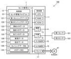
- FIG. 2 schematically illustrates an example of the hardware configuration of the sensor management unit 1 according to the present embodiment.
- the control unit 11, the storage unit 12, the communication interface 13, the external interface 14, the input device 15, the output device 16, and the drive 17 are electrically connected.
- the communication interface and the external interface are described as “communication I / F” and “external I / F”, respectively.
- the control unit 11 includes a hardware processor such as a central processing unit (CPU), a random access memory (RAM), and a read only memory (ROM), and is configured to execute information processing based on a program and various data. Ru.
- the storage unit 12 is an example of “memory”, and is configured of, for example, a hard disk drive, a solid state drive, or the like.
- the storage unit 12 includes a sensor management program 81, first sensing data 121, second sensing data 122, static metadata 123, dynamic metadata 124, processing metadata 125, management data 126, and setting. Data 127, sensing data ID 128, metadata ID 129 and the like are stored.
- the first sensing data 121 is obtained by observing an object with the first sensor 101.
- the second sensing data 122 is obtained by observing the usage pattern of the first sensor 101 by the second sensor 102.
- Each metadata 123 to 125 indicates an attribute of the first sensor 101, and is associated with the first sensing data 121.
- the management data 126 includes information indicating the correspondence between the first sensing data 121 and the metadata 123 to 125 according to the association.
- the setting data 127 includes information indicating the operation setting of the first sensor 101.
- the sensing data ID 128 is used to identify the first sensing data 121.
- the metadata ID 129 is used to identify each of the metadata 123 to 125 associated with the corresponding first sensing data 121.
- the sensor management program 81 includes an instruction to cause the sensor management unit 1 to execute information processing (FIG. 8) for managing the first sensing data 121 and the metadata 123 to 125 described later. Details will be described later.
- the communication interface 13 is, for example, a wired LAN (Local Area Network) module, a wireless LAN module, or the like, and is an interface for performing wired or wireless communication via a network.
- the sensor management unit 1 performs data communication with the network server 2 via the communication interface 13.
- the external interface 14 is, for example, a USB (Universal Serial Bus) port, a dedicated port, or the like, and is an interface for connecting to an external device.
- the type and number of external interfaces 14 may be appropriately selected in accordance with the type and number of external devices to be connected.
- the sensor management unit 1 is connected to each sensor (101, 102) via the external interface 14.
- the type of the first sensor 101 may not be particularly limited, and may be appropriately selected according to the embodiment.
- the first sensor 101 may be, for example, an image sensor, an infrared sensor, a sound sensor, an optical sensor, a pressure sensor, an atmospheric pressure sensor, a temperature sensor, or the like.
- the first sensor 101 may be, for example, an environment sensor, a vital sensor, an on-vehicle sensor, a home security sensor, or the like.
- the environmental sensor is a sensor configured to be able to measure or detect environmental information related to atmospheric pressure, temperature, humidity, sound pressure, sound, ultraviolet light, illuminance, rainfall, gas and the like.
- the vital sensor is a sensor configured to be able to measure or detect vital information such as blood pressure, heart rate, electrocardiogram, body temperature, sleep state (microwave), activity amount, blood glucose level and the like.
- An on-vehicle sensor is a sensor mounted in vehicles, such as an image sensor, a laser sensor, and a sleep (microwave) sensor.
- Home security sensors are related to home security such as image sensors, infrared sensors, activity (voice) sensors, gas (CO2 etc.) sensors, current sensors, smart meters (sensors that measure the amount of power consumed by home appliances, lighting, etc.) It is a sensor configured to measure or detect information.
- the first sensing data 121 obtained by the first sensor 101 is, for example, image data, numerical data, voice data, language data, and the like.
- the first sensor 101 is appropriately disposed so as to be able to observe the state of the object.
- the type of the second sensor 102 may not be particularly limited as long as the usage mode of the first sensor 101 can be observed, and may be appropriately selected according to the embodiment.
- the second sensor 102 may be, for example, a temperature sensor, a GPS sensor, an acceleration sensor, an atmospheric pressure sensor, a geomagnetic sensor, a gyro sensor, or the like.
- the second sensor 102 is appropriately disposed so as to be able to observe the usage pattern of the first sensor 101.
- a temperature sensor is employed as the second sensor 102
- the second sensor 102 can observe the temperature around the first sensor 101. it can.
- the second sensor 102 is attached to a housing (not shown) of the first sensor 101, whereby the attitude of the first sensor 101 is For example, the direction can be observed.
- one first sensor 101 and one second sensor 102 are connected to the sensor management unit 1.
- the number of each of the first sensor 101 and the second sensor 102 connected to the sensor management unit 1 may not be limited to one, and may be two or more.
- a plurality of first sensors 101 may be connected to the sensor management unit 1.
- a plurality of second sensors 102 may be used.
- the number of sensors (101, 102) connected to the sensor management unit 1 may be appropriately determined according to the embodiment.
- the input device 15 is, for example, a device for performing input such as a mouse and a keyboard.
- the output device 16 is, for example, a device for outputting a display, a speaker or the like. A user who is a provider of sensing data can operate the sensor management unit 1 using the input device 15 and the output device 16.
- the drive 17 is, for example, a CD drive, a DVD drive, or the like, and is a drive device for reading a program stored in the storage medium 91.
- the type of drive 17 may be appropriately selected according to the type of storage medium 91.
- the sensor management program 81 may be stored in the storage medium 91.
- the storage medium 91 stores information such as a program by an electric, magnetic, optical, mechanical or chemical action so that information such as a computer or other device or program recorded on a machine can be read.
- the sensor management unit 1 may obtain the sensor management program 81 from the storage medium 91.
- a disc-type storage medium such as a CD or a DVD is illustrated.
- the type of storage medium 91 is not limited to the disc type, and may be other than the disc type.
- a storage medium other than the disk type for example, a semiconductor memory such as a flash memory can be mentioned.
- the control unit 11 may include a plurality of hardware processors.
- the hardware processor may be configured by a microprocessor, a field-programmable gate array (FPGA), a digital signal processor (DSP), and the like.
- the storage unit 12 may be configured by a RAM and a ROM included in the control unit 11.
- the input device 15 and the output device 16 may be omitted.
- the sensor management unit 1 may be connected to each sensor (101, 102) via the communication interface 13, not the external interface 14. In this case, the external interface 14 may be omitted.
- the sensor management unit 1 is comprised by one information processing apparatus in FIG. 2, you may be comprised by two or more information processing apparatuses.
- the hardware configuration of each information processing device may or may not match.
- the sensor management unit 1 may be a general-purpose desktop PC (Personal Computer), a tablet PC, a smartphone, a mobile phone other than a smartphone, a programmable logic controller (PLC), etc., in addition to an information processing device designed specifically for services. Good.
- PLC programmable logic controller
- FIG. 3 schematically illustrates an example of the hardware configuration of the network server 2 according to the present embodiment.
- the network server 2 is a computer to which the control unit 21, the storage unit 22, and the communication interface 23 are electrically connected.
- the communication interface is described as "communication I / F".
- control unit 21 includes a hardware processor such as a CPU, a RAM, and a ROM, and is configured to execute various information processing based on programs and data.
- the storage unit 22 includes, for example, a hard disk drive, a solid state drive, and the like, and stores the program 82, the providing side data catalog 221, the using side data catalog 222, and the like.
- the program 82 includes an instruction to cause the network server 2 to execute information processing (FIG. 11) for matching a provider and a use destination described later.
- the provider data catalog 221 is prepared for each provider and includes information indicating sensing data (first sensing data 121) that can be provided by the sensor (first sensor 101) of each sensor device 100.
- the use-side data catalog 222 is prepared for each use destination, and includes information indicating sensing data desired by the user.
- the provider data catalog 221 and the user data catalog 222 are used for matching of a provider and a user. Details will be described later.
- the communication interface 23, like the communication interface 13, is an interface for performing communication via a network.
- the communication interface 23 is, for example, a wired LAN module, a wireless LAN module, or the like.
- the network server 2 performs data communication with each sensor device 100 and each user terminal 3 via the communication interface 23.
- control unit 21 may include a plurality of hardware processors.
- the hardware processor may be configured by a microprocessor, an FPGA or the like.
- the storage unit 22 may be configured by a RAM and a ROM included in the control unit 21.
- the network server 2 may further include an input device and an output device as a user interface.
- the network server 2 may be a general-purpose server device, a general-purpose PC, or the like, in addition to an information processing device designed for service only.
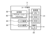
- FIG. 4 schematically illustrates an example of the hardware configuration of the user terminal 3 according to the present embodiment.
- the user terminal 3 is a computer in which the control unit 31, the storage unit 32, the communication interface 33, the input device 34, and the output device 35 are electrically connected.
- the communication interface is described as “communication I / F” as in FIGS. 2 and 3.
- the control unit 31 includes a CPU that is a hardware processor, a RAM, a ROM, and the like, similarly to the control units (11, 22), and is configured to execute various information processing based on programs and data.
- the storage unit 32 includes, for example, a hard disk drive, a solid state drive, and the like, and stores the application program 83 and the like.
- the application program 83 includes an instruction to cause the control unit 31 to execute predetermined information processing, and uses sensing data (first sensing data 121) provided from each user terminal 3.
- the type of application program 83 may not be particularly limited, and may be appropriately selected according to the embodiment.
- the communication interface 33 is an interface for performing communication via a network, similarly to the above-described communication interfaces (13, 23).
- the communication interface 33 is, for example, a wired LAN module, a wireless LAN module, or the like.
- the user terminal 3 performs data communication with the network server 2 via the communication interface 33.
- the input device 34 is, for example, a device for performing an input such as a mouse and a keyboard as the input device 15 described above.
- the output device 35 is, for example, a device for outputting a display, a speaker, and the like, as in the case of the output device 16.
- the user of the sensing data can operate the user terminal 3 using the input device 34 and the output device 35.
- control unit 31 may include a plurality of hardware processors.
- the hardware processor may be configured by a microprocessor, an FPGA, or the like.
- the storage unit 32 may be configured by a RAM and a ROM included in the control unit 31.
- the user terminal 3 may be a general-purpose desktop PC, a tablet PC, a smartphone, a mobile phone other than a smartphone, or the like, in addition to an information processing apparatus designed specifically for service.
- FIG. 5 schematically illustrates an example of the software configuration of the sensor management unit 1 according to the present embodiment.
- the control unit 11 of the sensor management unit 1 deploys the sensor management program 81 stored in the storage unit 12 in the RAM. Then, the control unit 11 causes the CPU to interpret the sensor management program 81 expanded in the RAM, and executes information processing based on the interpretation while controlling each component.
- the sensor management unit 1 includes, as software modules, a sensing data acquisition unit 111, a metadata generation unit 112, an identification code generation unit 113, a metadata management unit 114, and communication.
- a computer including the unit 115 and the catalog change unit 116 is configured.
- the sensing data acquisition unit 111 acquires the first sensing data 121 obtained by observing the target by the first sensor 101.
- the metadata generation unit 112 generates metadata indicating an attribute of the first sensor 101 with respect to the acquired first sensing data 121.
- the metadata generation unit 112 generates three types of metadata, static metadata 123, dynamic metadata 124, and processed metadata 125, as metadata indicating the attributes of the first sensor 101. .
- the static metadata 123 is configured to indicate an attribute related to the specification of the first sensor 101 that does not change over time. That is, the information held as the static metadata 123 basically relates to an attribute whose value is always constant and which is not likely to change depending on the usage form.
- the dynamic metadata 124 is an attribute of the first sensor 101 at the time when the first sensing data 121 is obtained, and indicates an attribute related to the usage pattern of the first sensor 101 that can dynamically change with the passage of time. Configured as.
- the attribute relating to the usage form of the first sensor 101 indicated by the dynamic metadata 124 is, for example, an attribute relating to the operation setting of the first sensor 101, an attribute relating to the installation situation of the first sensor 101, and the like.
- the information held as the dynamic metadata 124 is not limited to a constant value, but relates to an attribute that may change depending on the usage form. That is, the dynamic metadata 124 is an object to confirm (or track) whether or not the use form of the first sensor 101 has changed in order to determine, for example, the reliability, validity, etc. of the sensing data. Indicates information on the attribute to be acquired.
- the metadata generation unit 112 generates the dynamic metadata 124 based on the second sensing data 122 and the like obtained by observing the usage pattern of the first sensor 101 by the second sensor 102. .
- the processing metadata 125 relates to the feature amount of the acquired first sensing data 121.
- the metadata generation unit 112 generates the processed metadata 125 by analyzing the acquired first sensing data 121.
- the identification code generation unit 113 generates a sensing data ID 128 for identifying the first sensing data 121, and a metadata ID 129 for identifying each of the metadata 123 to 125.
- the metadata management unit 114 manages the generated metadata 123 to 125 in association with the first sensing data 121.
- the communication unit 115 performs at least one of transmission of the first sensing data 121 to which the metadata ID 129 is assigned and transmission of each of the metadata 123 to 125 to which the sensing data ID 128 is assigned to the external device such as the user terminal 3. .
- the catalog changing unit 116 changes the content of the provider data catalog 221 stored in the network server 2 in accordance with the change of the usage pattern of the first sensor 101.
- each software module of the sensor management unit 1 will be described in detail in an operation example described later.
- an example in which each software module of the sensor management unit 1 is realized by a general-purpose CPU is described.
- the method of implementing each software module may not be limited to such an example.
- Some or all of the software modules may be implemented by one or more dedicated processors. Further, regarding the software configuration of the sensor management unit 1, omission, replacement, and addition of software modules may be appropriately performed according to the embodiment.
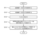
- FIG. 6 shows an example of a processing procedure of matching by the network server 2 according to the present embodiment.
- the processing procedure of the matching described below is only an example, and each processing may be changed as much as possible.
- steps may be omitted, replaced, or added as appropriate, according to the embodiment.
- Step S11 and S12 First, in step S ⁇ b> 11, the control unit 21 of the network server 2 acquires a providing-side data catalog 221 indicating sensing data that can be provided by each sensor device 100. In the next step S12, the control unit 21 acquires the use-side data catalog 222 indicating the sensing data desired by the user.
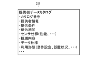
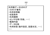
- FIG. 7A schematically illustrates an example of the provider-side data catalog 221 according to the present embodiment.
- the provider-side data catalog 221 according to the present embodiment includes information such as catalog number, provider information, provision condition, provision period, sensor specification, observation content, data specification, usage form and the like.
- the control unit 21 may appropriately generate the provider data catalog 221 by acquiring various information registered in the provider data catalog 221.
- the catalog number is a number for identifying the provider data catalog 221.
- the control unit 21 may appropriately generate an arbitrary number not used for the other providing side data catalog 221, and set the generated number as the catalog number.
- provider information is information for specifying the provider of sensing data, For example, a provider's name (personal name or organization name), a provider's contact point etc. may be included.
- the information on the provision conditions defines the conditions under which the provision of sensing data is permitted.
- the provision conditions include, for example, usage of sensing data (commercial / non-commercial / no restriction), scope of provision (providing to third party / not permitted), access right (replication impossible / replication possible / modification possible / processable) Conditions such as presence or absence of personal information, presence or absence of anonymous processing information, and payment types of expenses for use of sensing data may be included.
- Information on the provision period defines a period for which provision of sensing data is permitted (for example, the start date and end date of the provision).
- the control unit 21 receives the input or designation from the provider via each sensor device 100 or other information processing apparatus when generating the provider-side data catalog 221, thereby providing provider information, provision conditions, and provision. You may acquire each information of a period.
- the information on the sensor specification indicates an attribute on the specification of the first sensor 101, and may include, for example, information on the performance of the first sensor 101, device information, information on an initial installation condition, and the like.
- the information related to the performance of the first sensor 101 may include, for example, information such as the sensitivity limit of the first sensor 101, the dynamic range, the settable range of the spatial resolution, and the settable range of the sampling frequency.
- the device information of the first sensor 101 may include, for example, information such as the name of the first sensor 101, the description of the first sensor 101, and the like.
- the information on the initial installation condition of the first sensor 101 may include, for example, information such as a proper noun of the installation place of the first sensor 101.
- the information about the observation content indicates the attribute of the observation performed using the first sensor 101, and, for example, the name of the observation (for example, environmental observation), the explanation about the observation, and the name of the target for observation (for example, A establishment) ,
- the description about the observation object, the name of the observation index (for example, temperature, humidity, etc.), the explanation about the observation index, etc. may be included.
- the data specification information indicates an attribute related to the specification of the first sensing data 121 obtained by the first sensor 101.
- the name of the observed value (temperature value, maximum power consumption value, etc.) indicated by the first sensing data 121, It may include information such as the explanation of the observation value and the unit of the observation value.
- the control unit 21 When the control unit 21 generates the provider-side data catalog 221, the sensor specification, the observation content, and the data specification are obtained from the static metadata 123 associated with the first sensor 101 or the first sensing data 121 of each sensor device 100. Of each information may be acquired.
- the information on the usage mode indicates an attribute of the first sensor 101 that may change according to the usage mode, and may include, for example, information on operation setting of the first sensor 101 and information on the installation status of the first sensor 101 .
- the information on the operation setting of the first sensor 101 may include, for example, information such as a set value of the measurement range of the first sensor 101, a set value of resolution of the measurement range, and a set value of the sampling frequency.
- the information on the installation state of the first sensor 101 may include, for example, information such as the installation angle of the first sensor 101, the temperature around the first sensor 101, and the distance between the first sensor 101 and the observation target. Good.
- the control unit 21 may obtain information on the usage form from the dynamic metadata 124 associated with each sensor device 100 or the first sensing data 121.
- FIG. 7B schematically illustrates an example of the use-side data catalog 222 according to the present embodiment.
- the use-side data catalog 222 according to the present embodiment includes information such as catalog number, user information, collection condition, use period, sensor specification, observation content, data specification, use form and the like.
- the control unit 21 receives input or designation from the user via each user terminal 3 or other information processing apparatus, and acquires various information to be registered in the use-side data catalog 222.
- the data catalog 222 may be generated as appropriate.
- the catalog number is the same as the catalog number of the provider data catalog 221.
- each information of user information, collection condition, use period, sensor specification, observation content, data specification, and use form is the provider information of the above-mentioned provider data catalog 221, provision condition, provision period, sensor specification, observation It corresponds to each information of content, data specification, and usage form.
- the user information is information for identifying the user of the sensing data.
- the information on receipt conditions defines conditions for accepting provision of sensing data.
- the information on the usage period defines a period (for example, start date and time and usage end date and time of use) for which provision of sensing data is desired or desired to be provided.
- the information on the sensor specification indicates an attribute on the specification of the sensor for which it is desired to provide sensing data.
- the information on the content of observation indicates the attribute of the observation for which it is desired to provide sensing data.
- the data specification information indicates an attribute related to the specification of sensing data desired to be provided.
- the information on the use form indicates an attribute that may change according to the use form of the sensor for which provision of sensing data is desired.
- each information of user information, collection condition, usage period, sensor specification, observation content, data specification, and usage form are the provider information of the above-mentioned provider data catalog 221, provision condition, provision period, sensor It may be the same as the information of the specification, the observation content, the data specification, and the usage form.
- the generation of the provider data catalog 221 and the user data catalog 222 may not be performed by the network server 2.
- the provider data catalog 221 may be generated by each sensor device 100 or another information processor of the provider.
- the use-side data catalog 222 may be generated by each user terminal 3 or another information processing apparatus of the user.
- the control unit 21 may acquire the provider data catalog 221 from each sensor device 100 or another information processor of the provider via the network.
- the control unit 21 may acquire the use-side data catalog 222 from each user terminal 3 or another information processing apparatus of the user via the network.
- Steps S13 and S14 In the next step S13, the control unit 21 matches the provision source with the use destination by collating each item of the provision side data catalog 221 with each item of the use side data catalog 222. In the next step S14, based on the result of the matching, the sensor device 100 (first sensor 101) capable of providing sensing data (first sensing data 121) satisfying the user's request is extracted.
- the control unit 21 provides the provision condition of the provider data catalog 221, the provision period, the sensor specification, the observation content, the data specification, the collection condition of each item of the usage form and the usage data catalog 222, and uses Each item of a period, a sensor specification, an observation content, a data specification, and a utilization form is collated, and it is determined whether each item is suitable. As a result of the determination, when all or part of the items match, the control unit 21 senses the sensor device 100 corresponding to the provider data catalog 221 to satisfy the user request corresponding to the user data catalog 222. Extract data as available.
- control unit 21 determines that the sensor device 100 corresponding to the provider-side data catalog 221 can not provide sensing data satisfying the request of the user corresponding to the user-side data catalog 222 Do.
- the method of matching may not be limited to such an example, and may be appropriately determined according to the embodiment.
- Step S15 the control unit 21 permits the distribution of the sensing data (first sensing data 121) from the extracted sensor device 100 to the target user terminal 3.
- the control unit 21 transmits, to the extracted sensor device 100, a data flow permission instruction indicating that transmission of sensing data to the target user terminal 3 is permitted.
- each sensor device 100 transmits the first sensing data 121 obtained by observing the target with the first sensor 101 to the target user terminal 3 specified by the data flow permission command.
- the control unit 21 ends the matching process according to the present operation example.
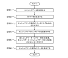
- FIG. 8 illustrates an example of a processing procedure for managing the first sensing data 121 by the sensor management unit 1 according to the present embodiment.
- FIG. 9 schematically illustrates an example of a management process of the first sensing data 121 by the sensor management unit 1 according to the present embodiment.
- the processing procedure described below is an example of the “sensor management method” in the present invention. However, the processing procedure described below is merely an example, and each processing may be changed as much as possible. In addition, according to the embodiment, steps may be omitted, replaced, or added as appropriate, according to the embodiment.
- Step S101 First, in step S101, the control unit 11 of the sensor management unit 1 operates as the sensing data acquisition unit 111, and acquires the first sensing data 121 obtained by observing the target by the first sensor 101.
- the sensor management unit 1 holds setting data 127 indicating the operation setting of the first sensor 101. Therefore, the control unit 11 refers to the setting data 127 to specify the operation setting of the first sensor 101.
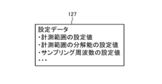
- FIG. 10 schematically illustrates an example of the setting data 127 according to the present embodiment.
- the setting data 127 includes, for example, information such as a setting value of the measurement range, a setting value of the resolution of the measurement range, and a setting value of the sampling frequency as information indicating the operation setting of the first sensor 101.
- the control unit 11 controls the operation of the first sensor 101 based on these pieces of information.
- control unit 11 controls the operation of the first sensor 101 based on the setting value of the measurement range indicated by the setting data 127 and the setting value of the resolution. Then, the control unit 11 sets a setting value indicated by the setting data 127 as a sampling frequency, and performs sampling processing of a signal output from the first sensor 101. Thereby, the control unit 11 can acquire the first sensing data 121.
- the method of acquiring the first sensing data 121 may not be limited to such an example, and may be appropriately determined according to the embodiment.
- control and sampling processing of the first sensor 101 may be performed by another information processing apparatus.
- the control unit 11 may acquire the first sensing data 121 from the other information processing apparatus.
- the control unit 11 proceeds to the next step S102.
- the first sensing data 121 may be configured to be time-series data having a certain time width, or may be configured to indicate an observation result of a temporary point.
- the configuration of the first sensing data 121 may not be particularly limited, and may be appropriately determined according to the embodiment.
- Step S102 In the next step S102, the control unit 11 operates as the metadata generation unit 112, and the static metadata 123, the dynamic metadata 124, and the processing metadata are applied to the first sensing data 121 acquired in step S101. Generate 125. After generating the metadata 123 to 125, the control unit 11 advances the process to the next step S103.
- the static metadata 123 is configured to indicate an attribute related to the specification of the first sensor 101 that does not change with time. As long as it is configured as such, the contents of the static metadata 123 may be appropriately determined according to the embodiment.
- the static metadata 123 may include, for example, an attribute related to the performance of the first sensor 101, an attribute related to device information of the first sensor 101, an attribute related to an initial installation condition of the first sensor 101, and the like.
- the control unit 11 obtains information corresponding to each item from the first information sensor 101 or another information processing apparatus that holds information on the specification of the first sensor 101, and generates static metadata 123 based on the obtained information. You may
- Dynamic metadata Dynamic metadata 124 is an attribute of the first sensor 101 at the time when the first sensing data 121 is obtained, and the first sensor 101 can change dynamically with the passage of time. It is configured to indicate the attribute regarding the usage form As long as it is configured as such, the contents of the dynamic metadata 124 may be appropriately determined according to the embodiment.
- the attribute relating to the usage form of the first sensor 101 indicated by the dynamic metadata 124 may include, for example, an attribute relating to the operation setting of the first sensor 101, an attribute relating to the installation state of the first sensor 101, and the like.
- the attributes related to the operation setting of the first sensor 101 are, for example, a set value of the measurement range, a set value of the resolution of the measurement range, a set value of the sampling frequency, and the like.
- information on the operation setting of the first sensor 101 is stored in the storage unit 12 as setting data 127. Therefore, the control unit 11 may acquire the information related to the operation setting of the first sensor 101 by referring to the setting data 127, and may generate the dynamic metadata 124 based on the acquired information.
- the attribute regarding the installation condition of the first sensor 101 is, for example, an installation angle of the first sensor 101, a temperature around the first sensor 101, a distance between the first sensor 101 and an observation target, and the like.
- the use form of the first sensor 101 is monitored by the second sensor 102 connected to the sensor management unit 1. Therefore, the control unit 11 may generate the dynamic metadata 124 based on the second sensing data 122 obtained by observing the usage pattern of the first sensor 101 by the second sensor 102.
- the second sensing data 122 obtained by the second sensor 102 is the temperature around the first sensor 101 Show. Therefore, even if the control unit 11 acquires the second sensing data 122 and generates data indicating the temperature around the first sensor 101 as the dynamic metadata 124 based on the acquired second sensing data 122. Good.
- the control unit 11 may acquire the second sensing data 122 and generate data indicating the installation angle of the first sensor 101 as the dynamic metadata 124 based on the acquired second sensing data 122. .
- the configuration of the dynamic metadata 124 may not be limited to such an example, and may be appropriately determined according to the embodiment. For example, at least one of the information on the attribute related to the operation setting of the first sensor 101 and the information on the attribute related to the installation status may be omitted. Also, the dynamic metadata 124 may include information on attributes regarding the usage form of the first sensor 101 other than the information on the attribute regarding the operation setting of the first sensor 101 and the information about the attribute regarding the installation status.
- control unit 11 may generate the dynamic metadata 124 regardless of the setting data 127 and the second sensing data 122.
- the control unit 11 may generate the dynamic metadata 124 based on the first sensing data 121.
- the control unit 11 analyzes the first sensing data 121 to specify the distance between the first sensor 101 and the observation target, and the specified distance May be generated as dynamic metadata 124.
- the dynamic metadata 124 is configured to indicate an attribute related to the usage pattern of the first sensor 101 at the time when the first sensing data 121 is obtained. Therefore, it is preferable that the point in time of the usage pattern of the first sensor 101 indicated by the dynamic metadata 124 coincide with the point in time when the first sensing data 121 is obtained. However, this “when the first sensing data 121 is obtained” may not be exact.
- the time of the usage pattern of the first sensor 101 indicated by the dynamic metadata 124 and the time of obtaining the first sensing data 121 may not completely coincide, and the dynamic metadata 124 They may be offset from each other as long as they do not have a fatal impact on usage.
- the point of time of usage of the first sensor 101 indicated by the dynamic metadata 124 and the point of time when the first sensing data 121 are obtained deviate from each other to such an extent that the utilization of the dynamic metadata 124 is not adversely affected. Is also included in the "point when the first sensing data 121 is obtained".
- control unit 11 may acquire the setting data 127 and the second sensing data 122 used to generate the dynamic metadata 124 at the same timing as the first sensing data 121, or the first sensing data 121. And may be acquired at different timings.
- the method of acquiring the second sensing data 122 may be the same as the method of acquiring the first sensing data 121 in step S101.
- the processed metadata 125 is configured to indicate the feature amount of the first sensing data 121 acquired in step S101. As long as it is configured as such, the content of the processing metadata 125 may be appropriately determined according to the embodiment.
- the control unit 11 can generate processing metadata 125 by executing a predetermined analysis process on the first sensing data 121 acquired in step S101.
- the type of predetermined analysis processing when generating the processing metadata 125 may not be particularly limited, and may be appropriately selected according to the embodiment.
- the predetermined analysis processing may be, for example, labeling processing, arithmetic processing for deriving a variation, arithmetic processing for deriving a vector value, conversion processing, cleansing processing, filtering processing, and the like.
- the conversion process is an arithmetic process for aligning units, scales, and the like. Cleansing processing is arithmetic processing for removing data other than the true value of sensing data.
- the filtering process is an arithmetic process for applying a filter such as an LPF, an HPF, or a BPF to sensing data.
- the type of the feature amount obtained as the processing metadata 125 by the analysis processing is not particularly limited as long as it indicates the feature of the first sensing data 121 acquired in step S101, and according to the embodiment May be selected appropriately.
- the feature amount obtained as the processing metadata 125 may be, for example, a label, a change amount, a vector value, an outlier, or the like.
- the contents of the dynamic metadata 124 and the processing metadata 125 depend on the timing and content of acquiring the first sensing data 121. Therefore, the control unit 11 newly generates the dynamic metadata 124 and the processing metadata 125 with respect to the acquired first sensing data 121 each time the processing of steps S101 and S102 is repeated.
- the content of the static metadata 123 does not depend on the first sensing data 121. Therefore, after creating the static metadata 123 once, the control unit 11 does not have to newly create the static metadata 123 for the same first sensor 101. That is, the control unit 11 may generate the static metadata 123 only when this step S102 is first executed.
- the timing of generating the static metadata 123 may be different from the timing of executing the present step S102.
- the control unit 11 connects, for example, the first sensor 101 to the sensor management unit 1 before executing step S101, and sets the static meta to the sensor management unit 1 at the time of initial setting for registering the first sensor 101. Data 123 may be generated.
- Step S103 In the next step S103, the control unit 11 operates as the identification code generation unit 113, and generates a sensing data ID 128 for identifying the first sensing data 121 acquired in step S101. Further, the control unit 11 generates a metadata ID 129 for identifying each of the metadata 123 to 125 generated in step S102.
- one sensing data ID 128 is assigned to one piece of first sensing data 121 acquired in step S101.
- one metadata ID 129 is assigned to one combination of static metadata 123, dynamic metadata 124, and processing metadata 125 corresponding to the first sensing data 121.
- the correspondence between the first sensing data 121 and the sensing data ID 128 and the correspondence between each of the metadata 123 to 125 and the metadata ID 129 may not be limited to such an example. It may be determined accordingly.
- the sensing data ID 128 and the metadata ID 129 may be configured by symbols such as letters, numbers, and codes.
- the control unit 11 does not assign to the other first sensing data 121, that is, an arbitrary symbol string different from the symbol string of the sensing data ID 128 paired with the other first sensing data 121. You may generate suitably as new sensing data ID128. Then, the control unit 11 may pair the generated new sensing data ID 128 with the first sensing data 121 acquired in step S101.
- control unit 11 does not assign to the other combinations of the metadata 123 to 125, that is, the symbol string of the metadata ID 129 paired with the other combinations of the metadata 123 to 125 A different arbitrary symbol string may be generated as new metadata ID 129 as appropriate. Then, the control unit 11 may pair the generated new metadata ID 129 with the combination of the metadata 123 to 125 generated in step S102.
- the sensing data ID 128 and the metadata ID 129 may be configured by a universal unique identifier (UUID) or a global unique identifier (GUID).
- UUID universal unique identifier
- GUID global unique identifier
- the control unit 11 may appropriately acquire the UUID or GUID from an external server apparatus or the like, and assign the acquired UUID or GUID to the sensing data ID 128 and the metadata ID 129, respectively. Thereby, the control unit 11 can generate each of the sensing data ID 128 and the metadata ID 129 by UUID or GUID.
- each of the sensing data ID 128 and the metadata ID 129 may not be limited to each example as described above, and may be appropriately determined according to the embodiment.
- the sensing data ID 128 is preferably configured to have a smaller amount of data than the first sensing data 121.
- the metadata ID 129 is preferably configured to have a smaller amount of data than the sum of the metadata 123 to 125.
- Step S104 In the next step S104, the control unit 11 operates as the metadata management unit 114, and associates each of the metadata 123 to 125 generated in step S102 with the first sensing data 121 acquired in step S101.
- control unit 11 associates each metadata 123 to 125 with the first sensing data 121 using the sensing data ID 128 and the metadata ID 129. Then, the control unit 11 updates the content of the management data 126 by adding information indicating the result of the association to the management data 126. Thus, the control unit 11 manages the correspondence between each of the metadata 123 to 125 and the first sensing data 121.
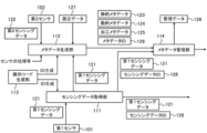
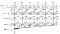
- FIG. 11 schematically illustrates the correspondence between the first sensing data 121 and each of the metadata 123 to 125.
- FIG. 12 schematically illustrates an example of the management data 126 according to the present embodiment. 11 and 12, the dynamic metadata 124 and the processing metadata 125 are newly generated each time the first sensing data 121 is acquired, whereas the static metadata 123 is one time. An example will not be newly generated after being generated.
- the first sensing data 121 such as "D0000” is acquired, and accordingly, the sensing data ID 128 such as “ID_D0000” is each first sensing data 121. It is tied to.
- dynamic metadata 124 such as “DM 0000” and processed metadata 125 such as “PM 0000” are generated for each first sensing data 121 by repeatedly executing step S 102.
- common static metadata 123 “SM0000” is generated for each first sensing data 121.
- a metadata ID 129 such as “ID_M0000” is associated with a combination of static metadata 123, dynamic metadata 124, and processing metadata 125 corresponding to each first sensing data 121.
- control unit 11 can associate the combination of the metadata 123 to 125 with the corresponding first sensing data 121 by associating the corresponding sensing data ID 128 with the metadata ID 129.
- the static metadata 123 “SM0000”, the dynamic metadata 124 “DM000n”, and the processing metadata 125 are linked by linking the sensing data ID 128 “ID_D000n” and the metadata ID 129 “ID_M000n”.
- the combination of “PM 000 n” is associated with the first sensing data 121 “D 000 n” (n is 0 to 5).
- the control unit 11 stores, as management data 126, information indicating the correspondence by this association.
- each record (row data) of the management data 126 indicates the correspondence by each association.
- each record of the management data 126 has a field for storing each of the sensing data ID 128 and the metadata ID 129.
- the control unit 11 stores the associated first sensing data 121 and each ID (128, 129) of each of the metadata 123 to 125 in each field of the new record to manage information indicating the result of the association as management data. It can be added to 126.
- the management data 126 is expressed in a table format.
- the data format of the management data 126 may not be limited to such a table format, and may be appropriately selected according to the embodiment.
- control unit 11 can associate each of the metadata 123 to 125 with the first sensing data 121. Further, the correspondence relationship by the association can be managed by the management data 126. After these processes are completed, the control unit 11 advances the process to the next step S105.
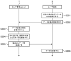
- Step S105 In the next step S105, the control unit 11 operates as the communication unit 115, and transmits the first sensing data 121 to which the metadata ID 129 is assigned to the user terminal 3 permitted to be distributed by the network server 2, and sensing At least one of the transmission of the metadata 123 to 125 assigned the data ID 128 is performed.
- the control unit 11 transmits either the first sensing data 121 to which the metadata ID 129 is assigned or the transmission of each of the metadata 123 to 125 to which the sensing data ID 128 is assigned. It is preferable to do only one or the other. At this time, the control unit 11 transmits the first sensing data 121 attached with the metadata ID 129 in the first period, and each meta added with the sensing data ID 128 in the second period different from the first period. Data 123 to 125 may be transmitted. When the transmission of the first sensing data 121 to which the metadata ID 129 is assigned or the metadata 123 to 125 to which the sensing data ID 128 is assigned is completed, the control unit 11 advances the process to the next step S106.
- control part 11 may transmit metadata ID129 and the 1st sensing data 121 using a different communication port in this step S105.
- control unit 11 may transmit the sensing data ID 128 and the metadata 123 to 125 using different communication ports.
- the second control unit 11 is different from the first communication port.
- the metadata ID 129 or the sensing data ID 128 may be transmitted to the target user terminal 3 by the communication port.
- the communication port is an endpoint for data communication.
- TCP Transmission Control Protocol
- UDP User Datagram Protocol
- the control unit 11 can perform data communication with the user terminal 3 at different communication ports.
- the port for transmitting each data (121, 123 to 125) and each ID (128, 129) may not be limited to such an example, and may be identical.
- control unit 11 transmits the first sensing data 121 to which the metadata ID 129 is assigned or the metadata 123 to 125 to which the sensing data ID 128 is assigned to the symmetrical user terminal 3 via the network server 2. Alternatively, it may be directly transmitted to the target user terminal 3 without passing through the network server 2.
- the network server 2 targets the first sensing data 121 to which the metadata ID 129 received from each sensor management unit 1 is added or the metadata 123 to 125 to which the sensing data ID 128 is added.
- Step S106 In the next step S106, the control unit 11 stores the first sensing data 121 and the metadata 123 to 125 in the storage unit 12.
- the timing at which the storage process of step S106 is performed may not be limited to such an example, and may be appropriately determined according to the embodiment.
- the control unit 11 may store the first sensing data 121 in the storage unit 12 at an arbitrary timing.
- the control unit 11 may store the metadata 123 to 125 in the storage unit 12 at an arbitrary timing after generating the metadata 123 to 125.
- control unit 11 ends the series of processes according to the present operation example.
- the application program 83 can use the first sensing data 121 or the metadata 123 to 125.
- the control unit 11 may execute the process from step S101 again. That is, the control unit 11 may repeatedly execute the series of processes of steps S101 to S106 until the observation of the object by the first sensor 101 is completed.
- the processing procedure for sensor management according to the present operation example may be changed as much as possible.
- the series of processes of steps S101 to S104 and S106 and the process of step S105 may be performed at different timings.
- the process of generating the sensing data ID 128 and the process of generating the metadata ID 129 may be performed in different steps.
- the control unit 11 may execute the process of association in step S104.
- control unit 11 when the contents of the dynamic metadata 124 are changed while repeatedly executing the processes of steps S101 and S102, the control unit 11 operates as the catalog changing unit 116, and the control unit 11 A command may be sent to the network server 2 to change the content of the usage pattern to conform to the content of the generated dynamic metadata 124. As a result, information on the latest usage form of the first sensor 101 can be reflected on the provider-side data catalog 221.
- the method of updating the contents of the usage form of the provider-side data catalog 221 may not be limited to such an example.
- the network server 2 does not wait for such a command, and the dynamic metadata 124 received from each sensor management unit 1 Information on the usage form of the target provider data catalog 221 may be changed based on the content.
- control unit 11 may receive a change in the operation setting of the first sensor 101 from the user via the network server 2, each user terminal 3, or another information processing apparatus.
- the information on the use form of the use-side data catalog 222 may be used to designate the change content of the operation setting of the first sensor 101. That is, the control unit 11 may receive, as a command instructing change of the operation setting of the first sensor 101, information related to the use form of the use-side data catalog 222.
- control unit 11 may correct the content of the setting data 127 to the content specified by the user, and change the operation setting of the first sensor 101 when acquiring the first sensing data 121.
- the operation setting of the first sensor 101 can be changed according to the request of each user.
- FIG. 13 illustrates an example of a processing procedure regarding a request for data transmission based on the sensing data ID 128 or the metadata ID 129 performed between the user terminal 3 and the sensor management unit 1 according to the present embodiment.
- the processing procedure of the data transmission request described below is only an example, and each processing may be changed as much as possible.
- steps may be omitted, replaced, or added as appropriate, according to the embodiment.
- Step S201 the control unit 31 of the user terminal 3 specifies an ID of data to be a request for transmission.
- the control unit 31 requests the target sensor management unit 1 (sensor device 100) to transmit data based on the ID specified in step S201.
- the first sensing data 121 to which the metadata ID 129 is assigned is transmitted from the sensor management unit 1 to the user terminal 3 in the step S105.
- the user terminal 3 holds the first sensing data 121 but does not hold the metadata 123 to 125 corresponding to the first sensing data 121. Therefore, in step S201, even if the control unit 31 designates the metadata ID 129 assigned to the first sensing data 121 received from the sensor management unit 1 as the ID of the data to be requested for transmission, as necessary. Good.
- the control unit 31 requests the target sensor management unit 1 to transmit the metadata 123 to 125 corresponding to the target first sensing data 121 based on the metadata ID 129. It is also good.
- step S105 the control unit 31 designates, as necessary, the sensing data ID 128 assigned to each of the metadata 123 to 125 received from the sensor management unit 1 as an ID of data to be transmitted. It is also good.
- step S202 the control unit 31 requests the target sensor management unit 1 to transmit the first sensing data 121 corresponding to each target metadata 123 to 125 based on the sensing data ID 128. It is also good.
- the specification of the ID of the data to be requested for transmission may be performed manually by the user or may be performed automatically by information processing in the application program 83 or the like.
- the control unit 31 outputs a list of each ID (128, 129) to the output device 35 such as a display, and transmits the data via the input device 34.
- the specification of the ID of the data to be requested may be accepted.
- step S203 the control unit 11 of the sensor management unit 1 receives a request for data transmission based on the ID from the user terminal 3.
- the control unit 11 receives the request for transmission of the target first sensing data 121 or each of the metadata 123 to 125 based on the sensing data ID 128 or the metadata ID 129, the process proceeds to the next step S204.
- step S204 the control unit 11 extracts, from the storage unit 12, the first sensing data 121 or each metadata 123 to 125 to be transmitted, based on the received sensing data ID 128 or metadata ID 129. Then, in the next step S205, the control unit 11 operates as the communication unit 115, and transmits the extracted first sensing data 121 or the metadata 123 to 125 to the user terminal 3 of the request source.
- the control unit 11 receives from the user terminal 3 a request for transmission of the first sensing data 121 in accordance with the designation of the sensing data ID 128, the first sensing data 121 specified by the designated sensing data ID 128 is received. Are sent to the user terminal 3.
- the control unit 11 receives from the user terminal 3 a request for transmission of each of the metadata 123 to 125 accompanied by the specification of the metadata ID 129, each of the metadata 123 to 125 specified by the specified metadata ID 129 Send 125 to the user terminal 3.
- Step S206 the control unit 31 of the user terminal 3 receives the first sensing data 121 or the metadata 123 to 125.
- the user terminal 3 acquires the metadata 123 to 125 corresponding to the first sensing data 121 received earlier, or the first sensing data 121 corresponding to each metadata 123 to 125 received earlier can do.
- the user terminal 3 acquires each metadata 123 to 125 corresponding to the first sensing data 121 received earlier, based on the received metadata ID 129, as necessary. Can.
- both sensing data IDs 128 for identifying the corresponding first sensing data 121 are transmitted. Be done.
- the user terminal 3 acquires the first sensing data 121 corresponding to each of the metadata 123 to 125 received earlier, as necessary, based on the received sensing data ID 128. Can. Therefore, according to the present embodiment, the availability of the first sensing data 121 and the metadata 123 to 125 in the user terminal 3 can be secured.
- the sensing data ID 128 can be configured to have a smaller amount of data than the first sensing data 121 itself, and the metadata ID 129 is configured to have a smaller amount of data than the total of each of the metadata 123 to 125 It is possible. Therefore, the communication amount in each of the case of transmitting the combination of the metadata ID 129 and the first sensing data 121 and the case of transmitting the combination of the sensing data ID 128 and each of the metadata 123 to 125 is the first sensing data 121 and each metadata It is smaller than the amount of communication in the case of transmitting the combination of 123 to 125.
- the communication amount for transmitting the first sensing data 121 and the metadata 123 to 125 is reduced without impairing the availability of the first sensing data 121 and the metadata 123 to 125. be able to.
- the metadata according to the present embodiment includes at least one of the dynamic metadata 124 and the processing metadata 125.
- the dynamic metadata 124 indicates attributes related to the usage of the sensor that can change dynamically as time passes.
- the processing metadata 125 indicates information on the feature amount of the first sensing data 121. Therefore, if the timing to obtain the first sensing data 121 is different, the contents of the generated dynamic metadata 124 and the processing metadata 125 may be different.
- the dynamic metadata 124 and the processing metadata 125 be generated each time the first sensing data 121 is obtained by the step S102.
- the data amount of metadata including the dynamic metadata 124 and the processing metadata 125 increases. .
- the communication amount required to transmit the first sensing data 121 and the metadata is increased.
- the present embodiment even in the present case where the data amount of metadata tends to increase, by using the sensing data ID 128 and the metadata ID 129, the first sensing data 121 and the metadata can be obtained. It is possible to reduce the amount of communication required for transmission. That is, the present technology for suppressing the communication amount required for transmitting the first sensing data 121 and metadata using the sensing data ID 128 and the metadata ID 129 includes at least one of the dynamic metadata 124 and the processing metadata 125. In this case, it is more effective to increase the amount of metadata data.
- the sensor device 100 (sensor management unit 1) is connected to the network server 2 via the network, and the first sensing data 121 is sent to the user terminal 3 of each user according to the result of matching by the network server 2.
- the method of providing the first sensing data 121 may not be limited to such an example, and may be appropriately determined according to the embodiment.
- the network server 2 may be omitted, and the sensor device 100 may provide the first sensing data 121 and the metadata 123 to 125 to each user terminal 3 in response to a request from each user terminal 3.
- step S102 of the above embodiment the control unit 11 of the sensor management unit 1 can generate dynamic metadata 124 based on the second sensing data 122 obtained by the second sensor 102.
- the method of generating the dynamic metadata 124 may not be limited to such an example, and the control unit 11 may generate the dynamic metadata 124 not based on the second sensing data 122. . In this case, the second sensor 102 may be omitted.
- the metadata generated in step S 102 may include static metadata 123, dynamic metadata 124, and processing metadata 125. However, at least one of the static metadata 123, the dynamic metadata 124, and the processing metadata 125 may be omitted. Also, the metadata may include other types of metadata.
- one metadata ID 129 is assigned to one combination of the static metadata 123, the dynamic metadata 124, and the processing metadata 125 corresponding to the first sensing data 121.
- the method of assigning the metadata ID may not be limited to such an example, and may be appropriately determined according to the embodiment.
- metadata IDs may be individually assigned to the metadata 123 to 125, respectively.
- the control unit 11 of the sensor management unit 1 transmits the first sensing data 121 to which the metadata ID 129 is assigned and the transmissions of the metadata 123 to 125 to which the sensing data ID 128 is assigned by the process of step S105.
- the transmission content of the sensor management unit 1 may not be limited to such an example.
- the sensor management unit 1 may have a mode for collectively transmitting the first sensing data 121 and the metadata 123 to 125, in addition to the mode for executing the process of step S105.
- the first sensing data 121 acquired in step S101 and the dynamic metadata 124 and processing metadata 125 generated in step S102 are accumulated in the storage unit 12 of the sensor management unit 1. Therefore, the sensor management unit 1 may discard the first sensing data 121, the dynamic metadata 124, and the processing metadata 125 beyond the predetermined storage period from the storage unit 12.
- each user terminal 3 transmits the first sensing data 121 or the first sensing data 121 to each sensor management unit 1 (sensor device 100) based on the sensing data ID 128 or the metadata ID 129 by the processes of steps S201 to S206.
- the data transmission of each metadata 123 to 125 is requested.
- the storage destinations of the first sensing data 121 and the metadata 123 to 125 may not be limited to each sensor management unit 1, and may be appropriately selected according to the embodiment.
- each sensor management unit 1 may transfer the first sensing data 121 and the metadata 123 to 125 to an external storage device such as a NAS (Network Attached Storage). In this case, each user terminal 3 may request the external storage device to transmit the data.
- NAS Network Attached Storage
- the sensor management unit 1 in order to change the contents of the provider data catalog 221 based on the dynamic metadata 124, the sensor management unit 1 includes the catalog change unit 117 as a software module. However, the catalog changing unit 117 may be omitted.
- the sensing data ID 128 and the metadata ID 129 are used to associate the first sensing data 121 with each of the metadata 123 to 125.
- the method of associating the first sensing data 121 with each of the metadata 123 to 125 may not be limited to such an example, and may be appropriately determined according to the embodiment.
- the first sensing data 121 may be associated with each of the metadata 123 to 125 regardless of the sensing data ID 128 and the metadata ID 129.
- control unit 11 transmits all of the static metadata 123, the dynamic metadata 124, and the processing metadata 125 at one time in step S105.
- transmission of at least part of the static metadata 123, the dynamic metadata 124, and the processing metadata 125 may be omitted in step S105.
- the control unit 11 may omit the transmission of the static metadata 123 after transmitting the static metadata 123 once.
- the sensor device 100 (the sensor management unit 1) transmits the second sensing data 122 to the external device such as the user terminal 3 together with the first sensing data 121 or in place of the first sensing data 121. May be provided.
- the sensor management unit 1 may generate the sensing data ID 128 and the metadata 123 to 125 for the second sensing data 122. That is, the second sensing data 122 may be treated as the "sensing data" of the present invention together with or instead of the first sensing data 121.
- the static metadata 123 may change according to the use form It relates to non-sex attributes.
- the changing / non-changing period may be limited to the period for providing sensing data. That is, as a result of the matching by the network server 2, the attribute of the first sensor 101 that may change within the period in which the first sensing data 121 is provided from the sensor management unit 1 to the target user terminal 3 is a dynamic meta It is treated as an object of the data 124, and the attribute of the first sensor 101 which is not possible may be treated as an object of the static metadata 123. In this case, the attribute indicated by the static metadata 123 may change (change) outside the period of providing the first sensing data 121.
- ... sensor management unit 11: control unit, 12: storage unit, 13: communication interface, 14: external interface, 15: input device, 16: output device, 17 ... drive, 100 ... sensor device, 101: first sensor (sensor) 102: second sensor 111 ... sensing data acquisition unit, 112 ... metadata generation unit, 113: identification code generation unit 114: metadata management unit 115: Communication unit 116: Catalog change unit 121 ... first sensing data (sensing data), 122 ... second sensing data, 123 ... static metadata, 124 ... dynamic metadata, 125 ... processing metadata, 126 ... management data, 127 ... setting data, 128 ... sensing data ID (first identification code), 129 ... metadata ID (second identification code), 2 ...
- Network server 21: control unit, 22: storage unit, 23: communication interface, 221 ... provider-side data catalog, 222 ... user side data catalog, 3 ...
- User terminal 31: control unit, 32: storage unit, 33: communication interface, 34 ... input device, 35 ... output device, 81: Sensor management program, 82 ... program, 83 ... program, 91: Storage medium
Abstract
本発明の一側面に係るセンサ管理ユニットは、センサにより対象を観測することで得られたセンシングデータを取得するセンシングデータ取得部と、取得した前記センシングデータに対して、前記センサの属性を示すメタデータを生成するメタデータ生成部と、前記センシングデータを識別するための第1の識別コード、及び前記メタデータを識別するための第2の識別コードを生成する識別コード生成部と、外部装置に対して、前記第2の識別コードを付与した前記センシングデータの送信、及び前記第1の識別コードを付与した前記メタデータの送信の少なくとも一方を行う通信部と、を備える。
Description
本発明は、センサ管理ユニット、センサ装置、センサ管理方法及びセンサ管理プログラムに関する。
近年、IoT(Internet of Things)技術の進化により、様々なデータを蓄積し、蓄積したデータを解析して、得られた知見をフィードバックする仕組みが活用され始めている。これに伴い、センサにより得られたセンシングデータの需要性及び共有化へのニーズが高まってきており、センシングデータの流通性を高めるための技術開発が活発化してきている。
例えば、特許文献1では、センサにより得られたセンシングデータを、当該センサを管理するセンサ管理装置から利用者のアプリケーションに送信するためのシステムが提案されている。具体的には、特許文献1で提案されているシステムは、センサ側メタデータとアプリ側メタデータとを取得する。センサ側メタデータは、センシングデータを出力するセンサに関する情報である。アプリ側メタデータは、センシングデータデータを利用するアプリケーションに関する情報である。
当該システムは、センサ側メタデータ及びアプリ側メタデータのマッチングを行うことで、アプリケーションの要求を満たすセンシングデータを提供可能なセンサを抽出する。そして、当該システムは、センサを管理するセンサ管理装置に対して、マッチングにより抽出されたセンサとアプリケーションとを特定したデータフロー制御指令を送信する。これにより、センサにより得られたセンシングデータを、センサを管理するセンサ管理装置から利用者のアプリケーションに送信させることができる。
また、例えば、特許文献2では、センサから出力される出力データに、出力データを識別するための識別情報、出力データの種別を示す種別情報、出力データの形式を示す形式情報等を付加するシステムが提案されている。当該システムによれば、センサから出力される出力データに付加される各情報に基づいて、当該出力データを識別したり、出力データの種別及び形式を特定したりすることができる。
上記のようなセンシングデータを流通させる従来の技術について、本件発明者らは、次のような問題点を見出した。すなわち、従来、センサから得られたセンシングデータに対して、当該センサの属性を示すメタデータを生成する場合、生成されたメタデータは、対応するセンシングデータと共に外部装置に送信される。そのため、センシングデータをセンサから得る度にメタデータを生成するようにすると、メタデータを付与する分だけ、センシングデータを外部装置に送信するのにかかる通信量が増大してしまうという問題が生じてしまう。
これに対して、センシングデータを外部装置に送信するのにかかる通信量を低減するために、定期又は不定期のタイミングで、メタデータの生成を省略することが考えられる。しかしながら、この方法では、省略を行ったタイミングで、メタデータの利用性が損なわれてしまうという新たな問題が生じてしまう。これは、センシングデータとメタデータとを入れ替えたケースでも同様である。つまり、本件発明者らは、従来の方法では、センシングデータ及びメタデータの利用性を損なうことなく、センシングデータ及びメタデータの送信にかかる通信量を低減するのは困難であるという問題点があることを見出した。
本発明は、一側面では、このような実情を鑑みてなされたものであり、その目的は、センシングデータ及びメタデータの利用性を損なうことなく、センシングデータ及びメタデータの送信にかかる通信量を低減するための技術を提供することである。
本発明は、上述した課題を解決するために、以下の構成を採用する。
すなわち、本発明の一側面に係るセンサ管理ユニットは、センサにより対象を観測することで得られたセンシングデータを取得するセンシングデータ取得部と、取得した前記センシングデータに対して、前記センサの属性を示すメタデータを生成するメタデータ生成部と、前記センシングデータを識別するための第1の識別コード、及び前記メタデータを識別するための第2の識別コードを生成する識別コード生成部と、外部装置に対して、前記第2の識別コードを付与した前記センシングデータの送信、及び前記第1の識別コードを付与した前記メタデータの送信の少なくとも一方を行う通信部と、を備える。
当該構成では、センシングデータを外部装置に送信する際には、メタデータを識別するための第2の識別コードが共に送信されるため、外部装置は、当該第2の識別コードに基づいて、受信したセンシングデータに対応するメタデータを必要に応じて取得することができる。同様に、メタデータを外部装置に送信する際には、センシングデータを識別するための第1の識別コードが共に送信されるため、外部装置は、当該第1の識別コードに基づいて、受信したメタデータに対応するセンシングデータを必要に応じて取得することができる。そのため、第2の識別コード及びセンシングデータの組み合わせ、又は第1の識別コード及びメタデータの組み合わせを外部装置に送信するようにすることで、外部装置におけるセンシングデータ及びメタデータの利用性を担保することができる。
また、一般的に、第1の識別コードのデータ量は、センシングデータそのもののデータ量よりも小さく、第2の識別コードのデータ量は、メタデータそのもののデータ量よりも小さい。そのため、第2の識別コード及びセンシングデータの組み合わせを送信するケース、並びに第1の識別コード及びメタデータの組み合わせを送信するケースそれぞれにおける通信量は、センシングデータ及びメタデータの組み合わせを送信するケースにおける通信量よりも小さくなる。更に、第1の識別コード及び第2の識別コードそれぞれに基づくセンシングデータ及びメタデータそれぞれの取得は、必ずしも常に実施されなければならない訳ではなく、その回数を抑えることが可能である。
したがって、当該構成によれば、センシングデータ及びメタデータの利用性を損なうことなく、センシングデータ及びメタデータの送信にかかる通信量を低減することができる。なお、センサの種類は、特に限定されなくてもよく、実施の形態に応じて適宜選択されてよい。例えば、センサは、画像センサ、赤外線センサ、音センサ、光センサ、圧力センサ、気圧センサ、温度センサ等であってよい。また、例えば、センサは、環境センサ(気圧、温度、湿度、音圧、音、紫外線、照度、降雨量、ガス等)、バイタルセンサ(血圧、心拍、心電、体温、睡眠(マイクロ波)、活動量、血糖値等)、車載センサ(画像センサ、レーザセンサ、睡眠(マイクロ波)センサ、等)、ホームセキュリティセンサ(画像センサ、赤外線センサ、活性度(音声)センサ、ガス(CO2等)センサ、電流センサ、スマートメータ(家電、照明等の電力使用量を計測するセンサ)等)等であってよい。これに応じて、センシングデータは、例えば、画像データ、数値データ、音声データ、言語データ等であってよい。また、外部装置は、センシングデータ及びメタデータを利用可能な、センサ管理ユニットとは異なる他の装置であれば特に限定されなくてもよく、例えば、ユーザ端末等であってよい。また、メタデータの内容は、センサ又はセンサにより得られるセンシングデータに関する何らかの情報を示すものであれば、特に限定されなくてもよく、実施の形態に応じて適宜決定されてよい。
上記一側面に係るセンサ管理ユニットにおいて、前記識別コード生成部は、ユニバーサルユニーク識別子(UUID:Universally Unique Identifier)又はグローバルユニーク識別子(GUID:Globally Unique Identifier)によって、前記第1の識別コード及び前記第2の識別コードを生成してもよい。当該構成によれば、第1の識別コード及び第2の識別コードがそれぞれ、センシングデータ及びメタデータそれぞれをグローバルでかつ一意に特定可能に構成されるため、他のシステムと共存可能なセンサ管理ユニットを提供することができる。
上記一側面に係るセンサ管理ユニットにおいて、前記メタデータは、時間の経過に伴い動的に変化し得る前記センサの利用形態に関する属性を示す動的メタデータ、及び前記センシングデータを解析することで生成される加工メタデータであって、前記センシングデータの特徴量に関する加工メタデータの少なくとも一方を含んでもよい。
動的メタデータは、時間の経過に伴い動的に変化し得るセンサの利用形態に関する属性を示す。加工メタデータは、センシングデータを解析することで生成される。よって、センシングデータを得るタイミングが異なれば、生成される動的メタデータ及び加工メタデータそれぞれの内容は相違し得る。
そのため、動的メタデータ及び加工メタデータは、センシングデータが得られる度に生成されるのが好ましい。しかしながら、センシングデータが得られる度に動的メタデータ及び加工メタデータを生成するようにすると、動的メタデータ及び加工メタデータのデータ量が増大し、これによって、センシングデータ及びメタデータを送信するのにかかる通信量が増大してしまう。
これに対して、当該構成によれば、メタデータのデータ量が増大しやすい本ケースであっても、第1の識別コード及び第2の識別コードを利用することで、センシングデータ及びメタデータの送信にかかる通信量を抑えることができる。つまり、第1の識別コード及び第2の識別コードを利用することで、センシングデータ及びメタデータの送信にかかる通信量を抑える本技術は、動的メタデータ及び加工メタデータの少なくとも一方を含むことでメタデータのデータ量が増大しやすい本ケースでより効果を発揮する。
なお、動的メタデータにより示されるセンサの利用形態に関する属性は、例えば、センサの動作設定に関する属性、センサの設置状況に関する属性等であってよい。センサの動作設定に関する属性は、例えば、計測範囲の設定値、計測範囲の分解能の設定値、サンプリング周波数の設定値等である。センサの設置状況に関する属性は、例えば、センサの設置角度、センサ周囲の温度、センサと観測対象との間の距離等である。
また、加工メタデータを生成する際の解析処理の種類は、特に限定されなくてもよく、実施の形態に応じて適宜選択されてよい。例えば、解析処理は、ラベリング処理、変化量を導出する演算処理、ベクトル値を導出する演算処理、単位、スケール等を揃えるための変換処理、センシングデータの真値以外のデータを除去するためのクレンジング処理、LPF(Low Pass Filter)、HPF(High Pass Filter)、BPF(Band Pass Filter)等のフィルタを利用したフィルタリング処理等であってよい。また、解析により加工メタデータとして得られる特徴量は、センシングデータの特徴を示すものである。特徴量の種類は、センシングデータの特徴を示すことができるのであれば、特に限定されなくてもよく、実施の形態に応じて適宜選択されてよい。例えば、特徴量は、ラベル、変化量、ベクトル値、外れ値等であってよい。
上記一側面に係るセンサ管理ユニットにおいて、前記通信部は、前記第1の識別コードの指定を伴う前記センシングデータの送信の要求を前記外部装置から受け付けた場合に、指定された前記第1の識別コードにより特定される前記センシングデータを前記外部装置に送信してもよく、前記第2の識別コードの指定を伴う前記メタデータの送信の要求を前記外部装置から受け付けた場合に、指定された前記第2の識別コードにより特定される前記メタデータを前記外部装置に送信してもよい。当該構成によれば、センシングデータを送信した後に必要に応じて対応するメタデータを送信し、メタデータを送信した後に必要に応じて対応するセンシングデータを送信することのできるセンサ管理ユニットを提供することができる。
上記一側面に係るセンサ管理ユニットは、生成した前記メタデータを前記センシングデータに関連付けて管理するメタデータ管理部を更に備えてもよい。当該構成によれば、センシングデータ及びメタデータを適切に管理可能なセンサ管理ユニットを提供することができる。
また、本発明の一側面に係るセンサ装置は、上記いずれかの形態に係るセンサ管理ユニットと、前記センサと、を備える。当該構成によれば、センシングデータ及びメタデータの利用性を損なうことなく、センシングデータ及びメタデータの送信にかかる通信量を低減したセンサ装置を提供することができる。
なお、上記各形態に係るセンサ管理ユニットの別の形態として、以上の各構成を実現する情報処理方法であってもよいし、プログラムであってもよいし、このようなプログラムを記憶した、コンピュータその他装置、機械等が読み取り可能な記憶媒体であってもよい。ここで、コンピュータ等が読み取り可能な記憶媒体とは、プログラム等の情報を、電気的、磁気的、光学的、機械的、又は、化学的作用によって蓄積する媒体である。
例えば、本発明の一側面に係るセンサ管理方法は、コンピュータが、センサにより対象を観測することで得られたセンシングデータを取得するステップと、取得した前記センシングデータに対して、前記センサの属性を示すメタデータを生成するステップと、前記センシングデータを識別するための第1の識別コード、及び前記メタデータを識別するための第2の識別コードを生成するステップと、外部装置に対して、前記第2の識別コードを付与した前記センシングデータの送信、及び前記第1の識別コードを付与した前記メタデータの送信の少なくとも一方を行うステップと、を実行する、情報処理方法である。
また、例えば、本発明の一側面に係るセンサ管理プログラムは、コンピュータに、センサにより対象を観測することで得られたセンシングデータを取得するステップと、取得した前記センシングデータに対して、前記センサの属性を示すメタデータを生成するステップと、前記センシングデータを識別するための第1の識別コード、及び前記メタデータを識別するための第2の識別コードを生成するステップと、外部装置に対して、前記第2の識別コードを付与した前記センシングデータの送信、及び前記第1の識別コードを付与した前記メタデータの送信の少なくとも一方を行うステップと、を実行させるための、プログラムである。
本発明によれば、センシングデータ及びメタデータの利用性を損なうことなく、センシングデータ及びメタデータの送信にかかる通信量を低減するための技術を提供することができる。
以下、本発明の一側面に係る実施の形態(以下、「本実施形態」とも表記する)を、図面に基づいて説明する。ただし、以下で説明する本実施形態は、あらゆる点において本発明の例示に過ぎない。本発明の範囲を逸脱することなく種々の改良や変形を行うことができることは言うまでもない。つまり、本発明の実施にあたって、実施形態に応じた具体的構成が適宜採用されてもよい。なお、本実施形態において登場するデータを自然言語により説明しているが、より具体的には、コンピュータが認識可能な疑似言語、コマンド、パラメータ、マシン語等で指定される。
§1 適用例
まず、図1を用いて、本発明が適用される場面の一例について説明する。図1は、本実施形態に係るセンサ装置100の利用場面の一例を模式的に例示する。図1の例では、本実施形態に係るセンサ装置100は、利用者のユーザ端末3にセンシングデータを提供する提供元として利用されている。ただし、本実施形態に係るセンサ装置100の利用方法は、このような例に限定される訳ではなく、実施の形態に応じて適宜決定されてよい。
まず、図1を用いて、本発明が適用される場面の一例について説明する。図1は、本実施形態に係るセンサ装置100の利用場面の一例を模式的に例示する。図1の例では、本実施形態に係るセンサ装置100は、利用者のユーザ端末3にセンシングデータを提供する提供元として利用されている。ただし、本実施形態に係るセンサ装置100の利用方法は、このような例に限定される訳ではなく、実施の形態に応じて適宜決定されてよい。
本実施形態に係るセンサ装置100は、対象を観測する第1センサ101、第1センサ101の利用形態を観測する第2センサ102、及び各センサ(101、102)に接続されるセンサ管理ユニット1を備えている。第1センサ101は、本発明の「センサ」の一例である。第2センサ102は、「サブセンサ」と称されてよい。各センサ(101、102)の種類は、観測対象に応じて適宜選択されてよい。
本実施形態に係るセンサ管理ユニット1は、第1センサ101により得られるセンシングデータ(後述する第1センシングデータ121)を管理するように構成された情報処理装置である。具体的に、センサ管理ユニット1は、第1センサ101により対象を観測することで得られたセンシングデータを取得する。続いて、センサ管理ユニット1は、取得したセンシングデータに対して、第1センサ101の属性を示すメタデータ(後述する各メタデータ123~125)を生成する。
メタデータの内容は、第1センサ101又は第1センサ101により得られるセンシングデータに関する何らかの情報を示すものであれば、特に限定されなくてもよく、実施の形態に応じて適宜決定されてよい。例えば、メタデータは、動的メタデータ(後述する動的メタデータ124)、及び加工メタデータ(後述する加工メタデータ125)の少なくとも一方を含んでよい。
動的メタデータは、時間の経過に伴い動的に変化し得る第1センサ101の利用形態に関する属性を示す。動的メタデータは、例えば、第2センサ102により第1センサ101の利用形態を観測することで得られたセンシングデータ(後述する第2センシングデータ122)に基づいて生成可能である。また、加工メタデータは、第1センサ101により得られたセンシングデータの特徴量に関するものであり、当該センシングデータを解析することで生成可能である。
更に、センサ管理ユニット1は、第1センサ101により得られたセンシングデータを識別するためのセンシングデータID(後述するセンシングデータID128)、及びメタデータを識別するためのメタデータID(後述するメタデータID129)を生成する。センシングデータIDは、本発明の「第1の識別コード」の一例である。メタデータIDは、本発明の「第2の識別コード」の一例である。
そして、センサ管理ユニット1は、外部装置に対して、メタデータIDを付与したセンシングデータの送信、及びセンシングデータIDを付与したメタデータの送信の少なくとも一方を行う。これによって、センサ管理ユニット1は、センシングデータ及びメタデータを外部装置に提供する。センシングデータ及びメタデータの提供先となる外部装置は、センサ管理ユニット1(センサ装置100)とは異なる他の装置であれば特に限定されなくてもよく、実施の形態に応じて適宜選択されてよい。本実施形態では、各ユーザ端末3が、本発明の「外部装置」の一例である。
具体的には、本実施形態では、センシングデータ及びメタデータは、ネットワークサーバ2を介してセンサ装置100から利用者のユーザ端末3に提供される。ネットワークサーバ2には、ネットワーク(不図示)を介して複数のセンサ装置100及び複数のユーザ端末3が接続される。ネットワークの種類は、例えば、インターネット、無線通信網、移動通信網、電話網、専用網等から適宜選択されてよい。
ネットワークサーバ2は、センシングデータの提供元(センサ装置100)と利用先(ユーザ端末3で実行されるアプリケーションソフト等)とを後述する方法によりマッチングし、利用先の要求を満たすセンシングデータを提供可能な提供元を抽出する。そして、ネットワークサーバ2は、マッチングの成立したセンサ装置100とユーザ端末3との間でのセンシングデータの流通を許可する。これにより、本実施形態では、各センサ装置100から適切なユーザ端末3にセンシングデータ及びメタデータが提供されるようになる。
以上のとおり、本実施形態に係るセンサ管理ユニット1(センサ装置100)は、センシングデータをユーザ端末3に送信する際に、メタデータを識別するためのメタデータIDを共に送信する。これにより、ユーザ端末3は、受信したメタデータIDに基づいて、受信したセンシングデータに対応するメタデータを必要に応じて取得することができる。同様に、本実施形態に係るセンサ管理ユニット1(センサ装置100)は、メタデータをユーザ端末3に送信する際に、センシングデータを識別するためのセンシングデータIDが共に送信される。これにより、ユーザ端末3は、センシングデータIDに基づいて、受信したメタデータに対応するセンシングデータを必要に応じて取得することができる。よって、本実施形態によれば、メタデータID及びセンシングデータの組み合わせ、又はセンシングデータID及びメタデータの組み合わせをユーザ端末3に送信するようにすることで、当該ユーザ端末3におけるセンシングデータ及びメタデータの利用性を担保することができる。
また、一般的に、センシングデータIDのデータ量は、センシングデータそのもののデータ量よりも小さく、メタデータIDのデータ量は、メタデータそのもののデータ量よりも小さい。そのため、メタデータID及びセンシングデータの組み合わせを送信するケース、並びにセンシングデータID及びメタデータの組み合わせを送信するケースそれぞれにおける通信量は、センシングデータ及びメタデータの組み合わせを送信するケースにおける通信量よりも小さくなる。更に、センシングデータID及びメタデータIDそれぞれに基づくセンシングデータ及びメタデータそれぞれの取得は、必ずしも常に実施されなければならない訳ではなく、その回数を抑えることができる。したがって、本実施形態によれば、センシングデータ及びメタデータの利用性を損なうことなく、センシングデータ及びメタデータの送信にかかる通信量を低減することができる。
§2 構成例
[ハードウェア構成]
<センサ管理ユニット(センサ装置)>
次に、図2を用いて、本実施形態に係るセンサ管理ユニット1のハードウェア構成の一例について説明する。図2は、本実施形態に係るセンサ管理ユニット1のハードウェア構成の一例を模式的に例示する。
[ハードウェア構成]
<センサ管理ユニット(センサ装置)>
次に、図2を用いて、本実施形態に係るセンサ管理ユニット1のハードウェア構成の一例について説明する。図2は、本実施形態に係るセンサ管理ユニット1のハードウェア構成の一例を模式的に例示する。
図2に示されるとおり、本実施形態に係るセンサ管理ユニット1は、制御部11、記憶部12、通信インタフェース13、外部インタフェース14、入力装置15、出力装置16、及びドライブ17が電気的に接続されたコンピュータである。なお、図2では、通信インタフェース及び外部インタフェースをそれぞれ「通信I/F」及び「外部I/F」と記載している。
制御部11は、ハードウェアプロセッサであるCPU(Central Processing Unit)、RAM(Random Access Memory)、ROM(Read Only Memory)等を含み、プログラム及び各種データに基づいて情報処理を実行するように構成される。記憶部12は、「メモリ」の一例であり、例えば、ハードディスクドライブ、ソリッドステートドライブ等で構成される。本実施形態では、記憶部12には、センサ管理プログラム81、第1センシングデータ121、第2センシングデータ122、静的メタデータ123、動的メタデータ124、加工メタデータ125、管理データ126、設定データ127、センシングデータID128、メタデータID129等が記憶される。
第1センシングデータ121は、第1センサ101により対象を観測することで得られる。第2センシングデータ122は、第2センサ102により第1センサ101の利用形態を観測することで得られる。各メタデータ123~125は、第1センサ101の属性を示し、第1センシングデータ121に関連付けられる。管理データ126は、当該関連付けによる第1センシングデータ121と各メタデータ123~125との対応関係を示す情報を含む。設定データ127は、第1センサ101の動作設定を示す情報を含む。センシングデータID128は、第1センシングデータ121を識別するために利用される。メタデータID129は、対応する第1センシングデータ121に関連付けられる各メタデータ123~125を識別するために利用される。センサ管理プログラム81は、後述する第1センシングデータ121及び各メタデータ123~125を管理するための情報処理(図8)をセンサ管理ユニット1に実行させる命令を含む。詳細は後述する。
通信インタフェース13は、例えば、有線LAN(Local Area Network)モジュール、無線LANモジュール等であり、ネットワークを介した有線又は無線通信を行うためのインタフェースである。センサ管理ユニット1は、この通信インタフェース13を介して、ネットワークサーバ2とデータ通信を行う。
外部インタフェース14は、例えば、USB(Universal Serial Bus)ポート、専用ポート等であり、外部装置と接続するためのインタフェースである。外部インタフェース14の種類及び数は、接続される外部装置の種類及び数に応じて適宜選択されてよい。本実施形態では、センサ管理ユニット1は、外部インタフェース14を介して、各センサ(101、102)と接続している。
第1センサ101の種類は、特に限定されなくてもよく、実施の形態に応じて適宜選択されてよい。第1センサ101は、例えば、画像センサ、赤外線センサ、音センサ、光センサ、圧力センサ、気圧センサ、温度センサ等であってよい。また、第1センサ101は、例えば、環境センサ、バイタルセンサ、車載センサ、ホームセキュリティセンサ等であってよい。環境センサは、気圧、温度、湿度、音圧、音、紫外線、照度、降雨量、ガス等に関する環境情報を計測又は検知可能に構成されたセンサである。バイタルセンサは、血圧、心拍、心電、体温、睡眠状態(マイクロ波)、活動量、血糖値等のバイタル情報を計測又は検知可能に構成されたセンサである。車載センサは、画像センサ、レーザセンサ、睡眠(マイクロ波)センサ等の車両に搭載されるセンサである。ホームセキュリティセンサは、画像センサ、赤外センサ、活性度(音声)センサ、ガス(CO2等)センサ、電流センサ、スマートメータ(家電、照明等の電力使用量を計測するセンサ)等のホームセキュリティに関する情報を計測又は検知可能に構成されたセンサである。これに応じて、第1センサ101により得られる第1センシングデータ121は、例えば、画像データ、数値データ、音声データ、言語データ等である。第1センサ101は、対象の状態を観測可能なように適宜配置される。
また、第2センサ102の種類は、第1センサ101の利用形態を観測可能であれば、特に限定されなくてもよく、実施の形態に応じて適宜選択されてよい。第2センサ102は、例えば、温度センサ、GPSセンサ、加速度センサ、気圧センサ、地磁気センサ、ジャイロセンサ等であってよい。この第2センサ102は、第1センサ101の利用形態を観測可能に適宜配置される。例えば、第2センサ102として温度センサを採用した場合、第1センサ101の近傍に第2センサ102を配置することで、当該第2センサ102により第1センサ101の周囲の温度を観測することができる。また、例えば、第2センサ102としてジャイロセンサを採用した場合、第1センサ101の筐体(不図示)に第2センサ102を取り付けることで、当該第2センサ102により第1センサ101の姿勢(例えば、向き)を観測することができる。
なお、図2の例では、センサ管理ユニット1には、1つの第1センサ101と1つの第2センサ102とが接続されている。しかしながら、センサ管理ユニット1に接続される第1センサ101及び第2センサ102それぞれの数は、1つに限られなくてもよく、2つ以上であってもよい。センサ管理ユニット1には、複数の第1センサ101が接続されてもよい。また、1つの第1センサ101の利用形態を観測するために、複数の第2センサ102が用いられてもよい。センサ管理ユニット1に接続される各センサ(101、102)の数は、実施の形態に応じて適宜決定されてよい。
入力装置15は、例えば、マウス、キーボード等の入力を行うための装置である。また、出力装置16は、例えば、ディスプレイ、スピーカ等の出力を行うための装置である。センシングデータの提供者となるユーザは、入力装置15及び出力装置16を利用して、センサ管理ユニット1を操作することができる。
ドライブ17は、例えば、CDドライブ、DVDドライブ等であり、記憶媒体91に記憶されたプログラムを読み込むためのドライブ装置である。ドライブ17の種類は、記憶媒体91の種類に応じて適宜選択されてよい。上記センサ管理プログラム81は、この記憶媒体91に記憶されていてもよい。
記憶媒体91は、コンピュータその他装置、機械等が記録されたプログラム等の情報を読み取り可能なように、当該プログラム等の情報を、電気的、磁気的、光学的、機械的又は化学的作用によって蓄積する媒体である。センサ管理ユニット1は、この記憶媒体91から、上記センサ管理プログラム81を取得してもよい。
ここで、図2では、記憶媒体91の一例として、CD、DVD等のディスク型の記憶媒体を例示している。しかしながら、記憶媒体91の種類は、ディスク型に限定される訳ではなく、ディスク型以外であってもよい。ディスク型以外の記憶媒体として、例えば、フラッシュメモリ等の半導体メモリを挙げることができる。
なお、センサ管理ユニット1の具体的なハードウェア構成に関して、実施形態に応じて、適宜、構成要素の省略、置換及び追加が可能である。例えば、制御部11は、複数のハードウェアプロセッサを含んでもよい。ハードウェアプロセッサは、マイクロプロセッサ、FPGA(field-programmable gate array)、DSP(digital signal processor)等で構成されてよい。記憶部12は、制御部11に含まれるRAM及びROMにより構成されてもよい。入力装置15及び出力装置16は省略されてもよい。各センサ(101、102)が通信インタフェースを備える場合、センサ管理ユニット1は、外部インタフェース14ではなく、通信インタフェース13を介して各センサ(101、102)と接続されてよい。この場合、外部インタフェース14は省略されてよい。また、図2では、センサ管理ユニット1は、1台の情報処理装置により構成されているが、複数台の情報処理装置により構成されてよい。センサ管理ユニット1が複数台の情報処理装置により構成される場合、各情報処理装置のハードウェア構成は、一致していてもよいし、一致していなくてもよい。また、センサ管理ユニット1は、サービス専用に設計された情報処理装置の他、汎用のデスクトップPC(Personal Computer)、タブレットPC、スマートフォン、スマートフォン以外の携帯電話、PLC(programmable logic controller)等であってよい。
<ネットワークサーバ>
次に、図3を用いて、本実施形態に係るネットワークサーバ2のハードウェア構成の一例について説明する。図3は、本実施形態に係るネットワークサーバ2のハードウェア構成の一例を模式的に例示する。
次に、図3を用いて、本実施形態に係るネットワークサーバ2のハードウェア構成の一例について説明する。図3は、本実施形態に係るネットワークサーバ2のハードウェア構成の一例を模式的に例示する。
図3に示されるとおり、本実施形態に係るネットワークサーバ2は、制御部21、記憶部22、及び通信インタフェース23が電気的に接続されたコンピュータである。なお、図3では、図2と同様に、通信インタフェースを「通信I/F」と記載している。
制御部21は、上記制御部11と同様に、ハードウェアプロセッサであるCPU、RAM、ROM等を含み、プログラム及びデータに基づいて各種情報処理を実行するように構成される。記憶部22は、例えば、ハードディスクドライブ、ソリッドステートドライブ等で構成され、プログラム82、提供側データカタログ221、利用側データカタログ222等を記憶する。
プログラム82は、後述する提供元及び利用先をマッチングする情報処理(図11)をネットワークサーバ2に実行させる命令を含む。提供側データカタログ221は、提供元毎に用意され、各センサ装置100のセンサ(第1センサ101)により提供可能なセンシングデータ(第1センシングデータ121)を示す情報を含む。一方、利用側データカタログ222は、利用先毎に用意され、利用者の所望するセンシングデータを示す情報を含む。提供側データカタログ221及び利用側データカタログ222は、提供元及び利用先のマッチングに利用される。詳細は後述する。
通信インタフェース23は、上記通信インタフェース13と同様に、ネットワークを介した通信を行うためのインタフェースである。通信インタフェース23は、例えば、有線LANモジュール、無線LANモジュール等である。ネットワークサーバ2は、この通信インタフェース23を介して、各センサ装置100及び各ユーザ端末3とデータ通信を行う。
なお、ネットワークサーバ2の具体的なハードウェア構成に関して、実施の形態に応じて、適宜、構成要素の省略、置換及び追加が可能である。例えば、制御部21は、複数のハードウェアプロセッサを含んでもよい。ハードウェアプロセッサは、マイクロプロセッサ、FPGA等で構成されてよい。記憶部22は、制御部21に含まれるRAM及びROMにより構成されてもよい。ネットワークサーバ2は、ユーザインタフェースとして入力装置及び出力装置を更に備えてもよい。また、ネットワークサーバ2は、サービス専用に設計された情報処理装置の他、汎用のサーバ装置、汎用のPC等であってもよい。
<ユーザ端末>
次に、図4を用いて、本実施形態に係るユーザ端末3のハードウェア構成の一例について説明する。図4は、本実施形態に係るユーザ端末3のハードウェア構成の一例を模式的に例示する。
次に、図4を用いて、本実施形態に係るユーザ端末3のハードウェア構成の一例について説明する。図4は、本実施形態に係るユーザ端末3のハードウェア構成の一例を模式的に例示する。
図4に示されるとおり、本実施形態に係るユーザ端末3は、制御部31、記憶部32、通信インタフェース33、入力装置34、及び出力装置35が電気的に接続されたコンピュータである。なお、図4では、図2及び図3と同様に、通信インタフェースを「通信I/F」と記載している。
制御部31は、上記各制御部(11、22)と同様に、ハードウェアプロセッサであるCPU、RAM、ROM等を含み、プログラム及びデータに基づいて各種情報処理を実行するように構成される。記憶部32は、例えば、ハードディスクドライブ、ソリッドステートドライブ等で構成され、アプリケーションプログラム83等を記憶する。
アプリケーションプログラム83は、所定の情報処理を制御部31に実行させる命令を含んでおり、各ユーザ端末3から提供されるセンシングデータ(第1センシングデータ121)を利用する。アプリケーションプログラム83の種類は、特に限定されなくてもよく、実施の形態に応じて適宜選択されてよい。
通信インタフェース33は、上記各通信インタフェース(13、23)と同様に、ネットワークを介した通信を行うためのインタフェースである。通信インタフェース33は、例えば、有線LANモジュール、無線LANモジュール等である。ユーザ端末3は、この通信インタフェース33を介して、ネットワークサーバ2とデータ通信を行う。
入力装置34は、上記入力装置15と同様に、例えば、マウス、キーボード等の入力を行うための装置である。また、出力装置35は、上記出力装置16と同様に、例えば、ディスプレイ、スピーカ等の出力を行うための装置である。センシングデータの利用者は、入力装置34及び出力装置35を利用して、ユーザ端末3を操作することができる。
なお、ユーザ端末3の具体的なハードウェア構成に関して、実施の形態に応じて、適宜、構成要素の省略、置換及び追加が可能である。例えば、制御部31は、複数のハードウェアプロセッサを含んでもよい。ハードウェアプロセッサは、マイクロプロセッサ、FPGA等で構成されてもよい。記憶部32は、制御部31に含まれるRAM及びROMにより構成されてもよい。また、ユーザ端末3は、サービス専用に設計された情報処理装置の他、汎用のデスクトップPC、タブレットPC、スマートフォン、スマートフォン以外の携帯電話等であってもよい。
[ソフトウェア構成]
次に、図5を用いて、本実施形態に係るセンサ管理ユニット1のソフトウェア構成の一例を説明する。図5は、本実施形態に係るセンサ管理ユニット1のソフトウェア構成の一例を模式的に例示する。
次に、図5を用いて、本実施形態に係るセンサ管理ユニット1のソフトウェア構成の一例を説明する。図5は、本実施形態に係るセンサ管理ユニット1のソフトウェア構成の一例を模式的に例示する。
センサ管理ユニット1の制御部11は、記憶部12に記憶されたセンサ管理プログラム81をRAMに展開する。そして、制御部11は、RAMに展開されたセンサ管理プログラム81をCPUにより解釈し、各構成要素を制御しながら、当該解釈に基づいた情報処理を実行する。これにより、図5に示されるとおり、本実施形態に係るセンサ管理ユニット1は、ソフトウェアモジュールとして、センシングデータ取得部111、メタデータ生成部112、識別コード生成部113、メタデータ管理部114、通信部115、及びカタログ変更部116を備えるコンピュータとして構成される。
センシングデータ取得部111は、第1センサ101により対象を観測することで得られた第1センシングデータ121を取得する。メタデータ生成部112は、取得した第1センシングデータ121に対して、第1センサ101の属性を示すメタデータを生成する。本実施形態では、メタデータ生成部112は、第1センサ101の属性を示すメタデータとして、静的メタデータ123、動的メタデータ124、及び加工メタデータ125の3種類のメタデータを生成する。
静的メタデータ123は、時間が経過しても変化しない第1センサ101の仕様に関する属性を示すように構成される。つまり、静的メタデータ123として保持される情報は、基本的には、その値が常に一定であり、利用形態に応じて変化する可能性のない属性に関するものである。
動的メタデータ124は、第1センシングデータ121が得られた時点における第1センサ101の属性であって、時間の経過に伴い動的に変化し得る第1センサ101の利用形態に関する属性を示すように構成される。動的メタデータ124により示される第1センサ101の利用形態に関する属性は、例えば、第1センサ101の動作設定に関する属性、第1センサ101の設置状況に関する属性等である。
動的メタデータ124として保持される情報は、その値が常に一定であるとは限られず、利用形態に応じて変化する可能性のある属性に関するものである。つまり、動的メタデータ124は、例えば、センシングデータの信頼性、有効性等を判定するために、第1センサ101の利用形態に関して、変化したか否かを確認(又は、追跡)する対象となり得る属性の情報を示す。本実施形態では、メタデータ生成部112は、第2センサ102により第1センサ101の利用形態を観測することで得られた第2センシングデータ122等に基づいて、動的メタデータ124を生成する。
加工メタデータ125は、取得した第1センシングデータ121の特徴量に関するものである。メタデータ生成部112は、取得した第1センシングデータ121を解析することで、当該加工メタデータ125を生成する。
識別コード生成部113は、第1センシングデータ121を識別するためのセンシングデータID128、及び各メタデータ123~125を識別するためのメタデータID129を生成する。メタデータ管理部114は、生成した各メタデータ123~125を第1センシングデータ121に関連付けて管理する。
通信部115は、ユーザ端末3等の外部装置に対して、メタデータID129を付与した第1センシングデータ121の送信、及びセンシングデータID128を付与した各メタデータ123~125の送信の少なくとも一方を行う。カタログ変更部116は、第1センサ101の利用形態の変更に伴い、ネットワークサーバ2に保存されている提供側データカタログ221の内容を変更する。
センサ管理ユニット1の各ソフトウェアモジュールに関しては後述する動作例で詳細に説明する。なお、本実施形態では、センサ管理ユニット1の各ソフトウェアモジュールがいずれも汎用のCPUにより実現される例について説明している。しかしながら、各ソフトウェアモジュールを実現する方法は、このような例に限定されなくてもよい。上記ソフトウェアモジュールの一部又は全部が、1又は複数の専用のプロセッサにより実現されてもよい。また、センサ管理ユニット1のソフトウェア構成に関して、実施の形態に応じて、適宜、ソフトウェアモジュールの省略、置換及び追加が行われてもよい。
§3 動作例
[マッチング処理]
次に、図6を用いて、ネットワークサーバ2による提供元及び利用先のマッチングに係る処理手順について説明する。図6は、本実施形態に係るネットワークサーバ2によるマッチングの処理手順の一例を示す。ただし、以下で説明するマッチングの処理手順は一例に過ぎず、各処理は可能な限り変更されてよい。また、以下で説明する処理手順について、実施の形態に応じて、適宜、ステップの省略、置換、及び追加が可能である。
[マッチング処理]
次に、図6を用いて、ネットワークサーバ2による提供元及び利用先のマッチングに係る処理手順について説明する。図6は、本実施形態に係るネットワークサーバ2によるマッチングの処理手順の一例を示す。ただし、以下で説明するマッチングの処理手順は一例に過ぎず、各処理は可能な限り変更されてよい。また、以下で説明する処理手順について、実施の形態に応じて、適宜、ステップの省略、置換、及び追加が可能である。
(ステップS11及びS12)
まず、ステップS11では、ネットワークサーバ2の制御部21は、各センサ装置100により提供可能なセンシングデータを示す提供側データカタログ221を取得する。次のステップS12では、制御部21は、利用者の所望するセンシングデータを示す利用側データカタログ222を取得する。
まず、ステップS11では、ネットワークサーバ2の制御部21は、各センサ装置100により提供可能なセンシングデータを示す提供側データカタログ221を取得する。次のステップS12では、制御部21は、利用者の所望するセンシングデータを示す利用側データカタログ222を取得する。
図7Aは、本実施形態に係る提供側データカタログ221の一例を模式的に例示する。本実施形態に係る提供側データカタログ221は、カタログ番号、提供者情報、提供条件、提供期間、センサ仕様、観測内容、データ仕様、利用形態等の情報を含む。ステップS11では、制御部21は、提供側データカタログ221に登録する各種情報を取得することで、提供側データカタログ221を適宜生成してもよい。
具体的に、カタログ番号は、提供側データカタログ221を識別するための番号である。制御部21は、提供側データカタログ221を生成する際に、他の提供側データカタログ221に利用されていない任意の番号を適宜生成して、生成した番号をカタログ番号に設定してもよい。
また、提供者情報は、センシングデータの提供者を特定するための情報であり、例えば、提供者の名称(個人名又は組織名)、提供者の連絡先等を含んでもよい。提供条件の情報は、センシングデータの提供を許諾する諸条件を規定する。提供条件には、例えば、センシングデータの利用用途(営利/非営利/制限無)、提供範囲(第三者への提供可/不可)、アクセス権(複製不可/複製可/改変可/加工可)、個人情報の有無、匿名加工情報の有無、センシングデータの利用に対する費用の支払類型等の条件が含まれてもよい。提供期間の情報は、センシングデータの提供を許諾する期間(例えば、提供の開始日時及び終了日時)を規定する。制御部21は、提供側データカタログ221を生成する際に、各センサ装置100又はその他の情報処理装置を介して提供者からの入力又は指定を受け付けることで、提供者情報、提供条件、及び提供期間の各情報を取得してもよい。
また、センサ仕様の情報は、第1センサ101の仕様に関する属性を示し、例えば、第1センサ101の性能に関する情報、機器情報、初期設置条件に関する情報等を含んでもよい。第1センサ101の性能に関する情報は、例えば、第1センサ101の感度限界、ダイナミックレンジ、空間分解能の設定可能範囲、サンプリング周波数の設定可能範囲等の情報を含んでもよい。第1センサ101の機器情報は、例えば、第1センサ101の名称、第1センサ101の説明等の情報を含んでもよい。第1センサ101の初期設置条件に関する情報は、例えば、第1センサ101の設置場所の固有名詞等の情報を含んでもよい。
観測内容に関する情報は、第1センサ101を用いて行われる観測の属性を示し、例えば、観測の名称(例えば、環境観測)、観測に関する説明、観測の対象物の名称(例えば、A事業所)、観測の対象物に関する説明、観測指標の名称(例えば、温度、湿度等)、観測指標に関する説明等を含んでもよい。データ仕様の情報は、第1センサ101により得られる第1センシングデータ121の仕様に関する属性を示し、例えば、第1センシングデータ121により示される観測値の名称(温度値、最大消費電力値等)、観測値の説明、観測値の単位等の情報を含んでもよい。制御部21は、提供側データカタログ221を生成する際に、各センサ装置100の第1センサ101又は第1センシングデータ121に関連付けられた静的メタデータ123から、センサ仕様、観測内容及びデータ仕様の各情報を取得してもよい。
また、利用形態に関する情報は、利用形態に応じて変化し得る第1センサ101の属性を示し、例えば、第1センサ101の動作設定に関する情報、第1センサ101の設置状況に関する情報を含んでもよい。第1センサ101の動作設定に関する情報は、例えば、第1センサ101の計測範囲の設定値、計測範囲の分解能の設定値、サンプリング周波数の設定値等の情報を含んでもよい。また、第1センサ101の設置状況に関する情報は、例えば、第1センサ101の設置角度、第1センサ101の周囲の温度、第1センサ101と観測対象との間の距離等の情報を含んでもよい。制御部21は、提供側データカタログ221を生成する際に、各センサ装置100又は第1センシングデータ121に関連付けられた動的メタデータ124から、利用形態に関する情報を取得してもよい。
一方、図7Bは、本実施形態に係る利用側データカタログ222の一例を模式的に例示する。本実施形態に係る利用側データカタログ222は、カタログ番号、利用者情報、収受条件、利用期間、センサ仕様、観測内容、データ仕様、利用形態等の情報を含む。ステップS12では、制御部21は、各ユーザ端末3又はその他の情報処理装置を介して利用者からの入力又は指定を受け付け、利用側データカタログ222に登録する各種情報を取得することで、利用側データカタログ222を適宜生成してもよい。
カタログ番号は、提供側データカタログ221のカタログ番号と同様である。また、利用者情報、収受条件、利用期間、センサ仕様、観測内容、データ仕様、及び利用形態の各情報は、上記提供側データカタログ221の提供者情報、提供条件、提供期間、センサ仕様、観測内容、データ仕様、及び利用形態の各情報に対応する。
利用者情報は、センシングデータの利用者を特定するための情報である。収受条件の情報は、センシングデータの提供を受諾する諸条件を規定する。利用期間の情報は、センシングデータの提供を受ける又は提供を受けることを所望する期間(例えば、利用の開始日時及び終了日時)を規定する。センサ仕様の情報は、センシングデータの提供を所望するセンサの仕様に関する属性を示す。観測内容に関する情報は、センシングデータの提供を所望する観測の属性を示す。データ仕様の情報は、提供を所望するセンシングデータの仕様に関する属性を示す。利用形態に関する情報は、センシングデータの提供を所望するセンサの利用形態に応じて変化し得る属性を示す。利用者情報、収受条件、利用期間、センサ仕様、観測内容、データ仕様、及び利用形態の各情報で規定される項目は、上記提供側データカタログ221の提供者情報、提供条件、提供期間、センサ仕様、観測内容、データ仕様、及び利用形態の各情報と同様であってよい。
なお、提供側データカタログ221及び利用側データカタログ222の生成は、ネットワークサーバ2によって行われなくてもよい。提供側データカタログ221は、各センサ装置100又は提供者の他の情報処理装置により生成されてもよい。また、利用側データカタログ222は、各ユーザ端末3又は利用者の他の情報処理装置により生成されてもよい。この場合、制御部21は、各センサ装置100又は提供者の他の情報処理装置からネットワークを介して提供側データカタログ221を取得してもよい。また、制御部21は、各ユーザ端末3又は利用者の他の情報処理装置からネットワークを介して利用側データカタログ222を取得してもよい。
(ステップS13及びS14)
次のステップS13では、制御部21は、提供側データカタログ221の各項目と利用側データカタログ222の各項目とを照合することで、提供元と利用先とをマッチングする。次のステップS14では、当該マッチングの結果に基づいて、利用者の要求を満たすセンシングデータ(第1センシングデータ121)を提供可能なセンサ装置100(第1センサ101)を抽出する。
次のステップS13では、制御部21は、提供側データカタログ221の各項目と利用側データカタログ222の各項目とを照合することで、提供元と利用先とをマッチングする。次のステップS14では、当該マッチングの結果に基づいて、利用者の要求を満たすセンシングデータ(第1センシングデータ121)を提供可能なセンサ装置100(第1センサ101)を抽出する。
マッチングの方法の一例として、制御部21は、提供側データカタログ221の提供条件、提供期間、センサ仕様、観測内容、データ仕様、及び利用形態の各項目と利用側データカタログ222の収受条件、利用期間、センサ仕様、観測内容、データ仕様、及び利用形態の各項目とを照合し、各項目同士が適合するか否かを判定する。当該判定の結果、制御部21は、項目の全て又は一部が適合した場合に、提供側データカタログ221に対応するセンサ装置100を、利用側データカタログ222に対応する利用者の要求を満たすセンシングデータを提供可能なものとして抽出する。一方、そうではない場合、制御部21は、提供側データカタログ221に対応するセンサ装置100を、利用側データカタログ222に対応する利用者の要求を満たすセンシングデータを提供可能なものではないと判定する。ただし、マッチングの方法は、このような例に限定されなくてもよく、実施の形態に応じて適宜決定されてよい。
(ステップS15)
次のステップS15では、制御部21は、抽出したセンサ装置100から対象のユーザ端末3へのセンシングデータ(第1センシングデータ121)の流通を許可する。当該許可の処理の一例として、制御部21は、抽出したセンサ装置100に対して、対象のユーザ端末3へのセンシングデータの送信を許可することを示すデータフロー許可指令を送信する。これに応じて、各センサ装置100は、データフロー許可指令により指定された対象のユーザ端末3に対して、第1センサ101により対象を観測することで得られた第1センシングデータ121の送信を開始する。抽出したセンサ装置100に対するデータ流通の許可が完了すると、制御部21は、本動作例に係るマッチングの処理を終了する。
次のステップS15では、制御部21は、抽出したセンサ装置100から対象のユーザ端末3へのセンシングデータ(第1センシングデータ121)の流通を許可する。当該許可の処理の一例として、制御部21は、抽出したセンサ装置100に対して、対象のユーザ端末3へのセンシングデータの送信を許可することを示すデータフロー許可指令を送信する。これに応じて、各センサ装置100は、データフロー許可指令により指定された対象のユーザ端末3に対して、第1センサ101により対象を観測することで得られた第1センシングデータ121の送信を開始する。抽出したセンサ装置100に対するデータ流通の許可が完了すると、制御部21は、本動作例に係るマッチングの処理を終了する。
[センシングデータの管理処理]
次に、図8及び図9を用いて、センサ管理ユニット1による第1センシングデータ121を管理するための処理手順について説明する。図8は、本実施形態に係るセンサ管理ユニット1による第1センシングデータ121を管理するための処理手順の一例を示す。図9は、本実施形態に係るセンサ管理ユニット1による第1センシングデータ121の管理過程の一例を模式的に例示する。以下で説明する処理手順は、本発明の「センサ管理方法」の一例である。ただし、以下で説明する処理手順は一例に過ぎず、各処理は可能な限り変更されてよい。また、以下で説明する処理手順について、実施の形態に応じて、適宜、ステップの省略、置換、及び追加が可能である。
次に、図8及び図9を用いて、センサ管理ユニット1による第1センシングデータ121を管理するための処理手順について説明する。図8は、本実施形態に係るセンサ管理ユニット1による第1センシングデータ121を管理するための処理手順の一例を示す。図9は、本実施形態に係るセンサ管理ユニット1による第1センシングデータ121の管理過程の一例を模式的に例示する。以下で説明する処理手順は、本発明の「センサ管理方法」の一例である。ただし、以下で説明する処理手順は一例に過ぎず、各処理は可能な限り変更されてよい。また、以下で説明する処理手順について、実施の形態に応じて、適宜、ステップの省略、置換、及び追加が可能である。
(ステップS101)
まず、ステップS101では、センサ管理ユニット1の制御部11は、センシングデータ取得部111として動作し、第1センサ101により対象を観測することで得られた第1センシングデータ121を取得する。
まず、ステップS101では、センサ管理ユニット1の制御部11は、センシングデータ取得部111として動作し、第1センサ101により対象を観測することで得られた第1センシングデータ121を取得する。
本実施形態では、センサ管理ユニット1は、第1センサ101の動作設定を示す設定データ127を保持している。そこで、制御部11は、設定データ127を参照し、第1センサ101の動作設定を特定する。
図10は、本実施形態に係る設定データ127の一例を模式的に例示する。設定データ127は、例えば、第1センサ101の動作設定を示す情報として、計測範囲の設定値、計測範囲の分解能の設定値、サンプリング周波数の設定値等の情報を含んでいる。制御部11は、これらの情報に基づいて、第1センサ101の動作を制御する。
具体的には、制御部11は、設定データ127により示される計測範囲の設定値及び分解能の設定値に基づいて、第1センサ101の動作を制御する。そして、制御部11は、設定データ127により示される設定値をサンプリング周波数に設定し、第1センサ101から出力される信号のサンプリング処理を行う。これにより、制御部11は、第1センシングデータ121を取得することができる。
ただし、第1センシングデータ121を取得する方法は、このような例に限定されなくてもよく、実施の形態に応じて適宜決定されてよい。例えば、上記第1センサ101の制御及びサンプリング処理は、他の情報処理装置により行われてもよい。この場合、制御部11は、当該他の情報処理装置から第1センシングデータ121を取得してもよい。第1センシングデータ121を取得すると、制御部11は、次のステップS102に処理を進める。
なお、第1センシングデータ121は、一定の時間幅を有する時系列データとなるように構成されてもよいし、一時点の観測結果を示すように構成されてもよい。第1センシングデータ121の構成は、特に限定されなくてもよく、実施の形態に応じて適宜決定されてよい。
(ステップS102)
次のステップS102では、制御部11は、メタデータ生成部112として動作し、ステップS101で取得した第1センシングデータ121に対して、静的メタデータ123、動的メタデータ124、及び加工メタデータ125を生成する。各メタデータ123~125を生成すると、制御部11は、次のステップS103に処理を進める。
次のステップS102では、制御部11は、メタデータ生成部112として動作し、ステップS101で取得した第1センシングデータ121に対して、静的メタデータ123、動的メタデータ124、及び加工メタデータ125を生成する。各メタデータ123~125を生成すると、制御部11は、次のステップS103に処理を進める。
(1)静的メタデータ
静的メタデータ123は、時間が経過しても変化しない第1センサ101の仕様に関する属性を示すように構成される。そのように構成される限り、静的メタデータ123の内容は、実施の形態に応じて適宜決定されてよい。静的メタデータ123は、例えば、第1センサ101の性能に関する属性、第1センサ101の機器情報に関する属性、第1センサ101の初期設置条件に関する属性等の情報を含んでもよい。制御部11は、第1センサ101又は第1センサ101の仕様に関する情報を保持する他の情報処理装置から各項目に対応する情報を取得し、取得した情報に基づいて静的メタデータ123を生成してよい。
静的メタデータ123は、時間が経過しても変化しない第1センサ101の仕様に関する属性を示すように構成される。そのように構成される限り、静的メタデータ123の内容は、実施の形態に応じて適宜決定されてよい。静的メタデータ123は、例えば、第1センサ101の性能に関する属性、第1センサ101の機器情報に関する属性、第1センサ101の初期設置条件に関する属性等の情報を含んでもよい。制御部11は、第1センサ101又は第1センサ101の仕様に関する情報を保持する他の情報処理装置から各項目に対応する情報を取得し、取得した情報に基づいて静的メタデータ123を生成してよい。
(2)動的メタデータ
動的メタデータ124は、第1センシングデータ121が得られた時点における第1センサ101の属性であって、時間の経過に伴い動的に変化し得る第1センサ101の利用形態に関する属性を示すように構成される。そのように構成される限り、動的メタデータ124の内容は、実施の形態に応じて適宜決定されてよい。動的メタデータ124により示される第1センサ101の利用形態に関する属性は、例えば、第1センサ101の動作設定に関する属性、第1センサ101の設置状況に関する属性等を含んでもよい。
動的メタデータ124は、第1センシングデータ121が得られた時点における第1センサ101の属性であって、時間の経過に伴い動的に変化し得る第1センサ101の利用形態に関する属性を示すように構成される。そのように構成される限り、動的メタデータ124の内容は、実施の形態に応じて適宜決定されてよい。動的メタデータ124により示される第1センサ101の利用形態に関する属性は、例えば、第1センサ101の動作設定に関する属性、第1センサ101の設置状況に関する属性等を含んでもよい。
第1センサ101の動作設定に関する属性は、例えば、計測範囲の設定値、計測範囲の分解能の設定値、サンプリング周波数の設定値等である。本実施形態では、第1センサ101の動作設定に関する情報は、設定データ127として記憶部12に記憶されている。そこで、制御部11は、設定データ127を参照することで、第1センサ101の動作設定に関する情報を取得し、取得した情報に基づいて、動的メタデータ124を生成してもよい。
また、第1センサ101の設置状況に関する属性は、例えば、第1センサ101の設置角度、第1センサ101の周囲の温度、第1センサ101と観測対象との間の距離等である。本実施形態では、センサ管理ユニット1に接続される第2センサ102によって、第1センサ101の利用形態が監視されている。そこで、制御部11は、第2センサ102により第1センサ101の利用形態を観測することで得られた第2センシングデータ122に基づいて、動的メタデータ124を生成してもよい。
具体例として、第2センサ102が温度センサであり、第1センサ101の近傍に配置されている場合、第2センサ102により得られる第2センシングデータ122は、第1センサ101の周囲の温度を示す。そこで、制御部11は、当該第2センシングデータ122を取得し、取得した第2センシングデータ122に基づいて、第1センサ101の周囲の温度を示すデータを動的メタデータ124として生成してもよい。
また、第2センサ102がジャイロセンサであり、第1センサ101の筐体に取り付けられている場合、第2センサ102により得られる第2センシングデータ122は、第1センサ101の傾きを示す。そこで、制御部11は、当該第2センシングデータ122を取得し、取得した第2センシングデータ122に基づいて、第1センサ101の設置角度を示すデータを動的メタデータ124として生成してもよい。
なお、動的メタデータ124の構成は、このような例に限定されなくてもよく、実施の形態に応じて適宜決定されてよい。例えば、上記第1センサ101の動作設定に関する属性の情報及び設置状況に関する属性の情報のうちの少なくとも一方は省略されてもよい。また、動的メタデータ124は、上記第1センサ101の動作設定に関する属性の情報及び設置状況に関する属性の情報以外の第1センサ101の利用形態に関する属性の情報を含んでもよい。
また、制御部11は、設定データ127及び第2センシングデータ122に依らず、動的メタデータ124を生成してもよい。例えば、制御部11は、第1センシングデータ121に基づいて、動的メタデータ124を生成してもよい。具体例として、第1センサ101が赤外線センサである場合、制御部11は、第1センシングデータ121を解析することで、第1センサ101と観測対象との間の距離を特定し、特定した距離を示すデータを動的メタデータ124として生成してもよい。
また、動的メタデータ124は、第1センシングデータ121が得られた時点における第1センサ101の利用形態に関する属性を示すように構成される。そのため、動的メタデータ124により示される第1センサ101の利用形態の時点と第1センシングデータ121が得られた時点とは一致しているのが好ましい。しかしながら、この「第1センシングデータ121が得られた時点」は、厳密でなくてもよい。
つまり、動的メタデータ124により示される第1センサ101の利用形態の時点と第1センシングデータ121が得られた時点とは、完全には一致していなくてもよく、動的メタデータ124の利用に致命的な影響を与えない限り、互いにずれていてもよい。この動的メタデータ124により示される第1センサ101の利用形態の時点と第1センシングデータ121が得られた時点とが動的メタデータ124の利用に致命的な影響を与えない程度に互いにずれている状態も、「第1センシングデータ121が得られた時点」に含まれるものとする。
したがって、制御部11は、動的メタデータ124の生成に利用する設定データ127及び第2センシングデータ122を、第1センシングデータ121と同一のタイミングで取得してもよいし、第1センシングデータ121とは異なるタイミングで取得してもよい。なお、第2センシングデータ122を取得する方法は、上記ステップS101における第1センシングデータ121を取得する方法と同様であってよい。
(3)加工メタデータ
加工メタデータ125は、ステップS101で取得した第1センシングデータ121の特徴量を示すように構成される。そのように構成される限り、加工メタデータ125の内容は、実施の形態に応じて適宜決定されてよい。制御部11は、ステップS101で取得した第1センシングデータ121に対して所定の解析処理を実行することで、加工メタデータ125を生成することができる。
加工メタデータ125は、ステップS101で取得した第1センシングデータ121の特徴量を示すように構成される。そのように構成される限り、加工メタデータ125の内容は、実施の形態に応じて適宜決定されてよい。制御部11は、ステップS101で取得した第1センシングデータ121に対して所定の解析処理を実行することで、加工メタデータ125を生成することができる。
なお、加工メタデータ125を生成する際の所定の解析処理の種類は、特に限定されなくてもよく、実施の形態に応じて適宜選択されてよい。当該所定の解析処理は、例えば、ラベリング処理、変化量を導出する演算処理、ベクトル値を導出する演算処理、変換処理、クレンジング処理、フィルタリング処理等であってよい。変換処理は、単位、スケール等を揃えるための演算処理である。クレンジング処理は、センシングデータの真値以外のデータを除去するための演算処理である。フィルタリング処理は、LPF、HPF、BPF等のフィルタをセンシングデータに適用するための演算処理である。
また、解析処理により加工メタデータ125として得られる特徴量の種類は、ステップS101で取得した第1センシングデータ121の特徴を示すものであれば、特に限定されなくてもよく、実施の形態に応じて適宜選択されてよい。加工メタデータ125として得られる特徴量は、例えば、ラベル、変化量、ベクトル値、外れ値等であってよい。
(4)その他
なお、動的メタデータ124及び加工メタデータ125の内容は、第1センシングデータ121を取得するタイミング及び内容に依存する。そのため、制御部11は、ステップS101及びS102の処理を繰り返す度に、取得した第1センシングデータ121に対して動的メタデータ124及び加工メタデータ125を新たに生成する。
なお、動的メタデータ124及び加工メタデータ125の内容は、第1センシングデータ121を取得するタイミング及び内容に依存する。そのため、制御部11は、ステップS101及びS102の処理を繰り返す度に、取得した第1センシングデータ121に対して動的メタデータ124及び加工メタデータ125を新たに生成する。
一方、静的メタデータ123の内容は、第1センシングデータ121には依存しない。そのため、制御部11は、静的メタデータ123を一度作成した後には、同一の第1センサ101に対して、静的メタデータ123を新たに生成しなくてもよい。つまり、制御部11は、本ステップS102を最初に実行する時のみ、静的メタデータ123を生成するようにしてもよい。
また、静的メタデータ123を生成するタイミングは、本ステップS102を実行するタイミングと異なっていてもよい。制御部11は、ステップS101を実行する前、例えば、第1センサ101をセンサ管理ユニット1に接続し、センサ管理ユニット1に第1センサ101を登録するための初期設定の際に、静的メタデータ123を生成してもよい。
(ステップS103)
次のステップS103では、制御部11は、識別コード生成部113として動作して、ステップS101で取得した第1センシングデータ121を識別するためのセンシングデータID128を生成する。また、制御部11は、ステップS102で生成した各メタデータ123~125を識別するためのメタデータID129を生成する。
次のステップS103では、制御部11は、識別コード生成部113として動作して、ステップS101で取得した第1センシングデータ121を識別するためのセンシングデータID128を生成する。また、制御部11は、ステップS102で生成した各メタデータ123~125を識別するためのメタデータID129を生成する。
本実施形態では、ステップS101で取得した1件の第1センシングデータ121に対して、1件のセンシングデータID128が付与される。これに対して、第1センシングデータ121に対応する静的メタデータ123、動的メタデータ124、及び加工メタデータ125の1つの組み合わせに対して、1件のメタデータID129が付与される。ただし、第1センシングデータ121とセンシングデータID128との対応関係、及び各メタデータ123~125とメタデータID129との対応関係はそれぞれ、このような例に限定されなくてもよく、実施の形態に応じて適宜決定されてよい。
例えば、センシングデータID128及びメタデータID129はそれぞれ、文字、数字、符号等の記号により構成されてよい。この場合、制御部11は、他の第1センシングデータ121に付与していない、すなわち、他の第1センシングデータ121と対になっているセンシングデータID128の記号列とは異なる任意の記号列を新たなセンシングデータID128として適宜生成してもよい。そして、制御部11は、生成した新たなセンシングデータID128を、ステップS101で取得した第1センシングデータ121と対にしてもよい。
同様に、制御部11は、各メタデータ123~125の他の組み合わせに付与していない、すなわち、各メタデータ123~125の他の組み合わせと対になっているメタデータID129の記号列とは異なる任意の記号列を新たなメタデータID129として適宜生成してもよい。そして、制御部11は、生成した新たなメタデータID129を、ステップS102で生成した各メタデータ123~125の組み合わせと対にしてもよい。
また、例えば、他のシステムとの共存性を確保するため、センシングデータID128及びメタデータID129は、ユニバーサルユニーク識別子(UUID)又はグローバルユニーク識別子(GUID)により構成されてもよい。この場合、制御部11は、外部のサーバ装置等からUUID又はGUIDを適宜取得し、取得したUUID又はGUIDを、センシングデータID128及びメタデータID129それぞれに割り当ててもよい。これにより、制御部11は、UUID又はGUIDによって、センシングデータID128及びメタデータID129それぞれを生成することができる。
なお、センシングデータID128及びメタデータID129それぞれの構成は、上記のような各例に限定されなくてもよく、実施の形態に応じて適宜決定されてよい。センシングデータID128は、第1センシングデータ121よりもデータ量が少なくなるように構成されるのが好ましい。また、メタデータID129は、各メタデータ123~125の合計よりもデータ量が少なくなるように構成されるのが好ましい。センシングデータID128及びメタデータID129を生成すると、制御部11は、次のステップS104に処理を進める。
(ステップS104)
次のステップS104では、制御部11は、メタデータ管理部114として動作し、ステップS102で生成した各メタデータ123~125を、ステップS101で取得した第1センシングデータ121に関連付ける。
次のステップS104では、制御部11は、メタデータ管理部114として動作し、ステップS102で生成した各メタデータ123~125を、ステップS101で取得した第1センシングデータ121に関連付ける。
本実施形態では、制御部11は、センシングデータID128及びメタデータID129を用いて、各メタデータ123~125を第1センシングデータ121に関連付ける。そして、制御部11は、当該関連付けの結果を示す情報を管理データ126に追加することで、当該管理データ126の内容を更新する。これにより、制御部11は、各メタデータ123~125と第1センシングデータ121との対応関係を管理する。
図11及び図12を用いて、これらの処理の具体例を詳細に説明する。図11は、第1センシングデータ121及び各メタデータ123~125の対応関係を模式的に例示する。図12は、本実施形態に係る管理データ126の一例を模式的に例示する。なお、図11及び図12では、動的メタデータ124及び加工メタデータ125は、第1センシングデータ121を取得する度に新たに生成されるのに対して、静的メタデータ123は、1度生成された後には新たに生成されない例を示す。
図11の例では、ステップS101が繰り返し実行されることで、「D0000」等の第1センシングデータ121が取得され、これに応じて、「ID_D0000」等のセンシングデータID128が各第1センシングデータ121に紐付けられている。一方、ステップS102が繰り返し実行されることで、各第1センシングデータ121に対して、「DM0000」等の動的メタデータ124及び「PM0000」等の加工メタデータ125が生成されている。また、各第1センシングデータ121に対して、共通の静的メタデータ123「SM0000」が生成されている。各第1センシングデータ121に対応する静的メタデータ123、動的メタデータ124、及び加工メタデータ125の組み合わせには、「ID_M0000」等のメタデータID129が紐付けられている。
この場合、制御部11は、対応するセンシングデータID128とメタデータID129とを紐付けることで、各メタデータ123~125の組み合わせを対応する第1センシングデータ121に関連付けすることができる。図11の例では、センシングデータID128「ID_D000n」とメタデータID129「ID_M000n」とが紐付けられることで、静的メタデータ123「SM0000」、動的メタデータ124「DM000n」、及び加工メタデータ125「PM000n」の組み合わせが、第1センシングデータ121「D000n」に関連付けられている(nは、0~5)。
制御部11は、この関連付けによる対応関係を示す情報を管理データ126として保存する。図12の例では、管理データ126の各レコード(行データ)は、各関連付けによる対応関係を示す。具体的には、管理データ126の各レコードは、センシングデータID128及びメタデータID129それぞれを格納するフィールドを有している。制御部11は、関連付けした第1センシングデータ121及び各メタデータ123~125の各ID(128、129)を新たなレコードの各フィールドに格納することで、当該関連付けの結果を示す情報を管理データ126に追加することができる。なお、図12の例では、管理データ126は、テーブル形式で表現されている。しかしながら、管理データ126のデータ形式は、このようなテーブル形式に限られなくてもよく、実施の形態に応じて適宜選択されてよい。
以上により、制御部11は、各メタデータ123~125を第1センシングデータ121に関連付けることができる。また、当該関連付けによる対応関係が、管理データ126によって管理された状態にすることができる。これらの処理が完了した後、制御部11は、次のステップS105に処理を進める。
(ステップS105)
次のステップS105では、制御部11は、通信部115として動作し、ネットワークサーバ2により流通を許可されたユーザ端末3に対して、メタデータID129を付与した第1センシングデータ121の送信、及びセンシングデータID128を付与した各メタデータ123~125の送信の少なくとも一方を行う。
次のステップS105では、制御部11は、通信部115として動作し、ネットワークサーバ2により流通を許可されたユーザ端末3に対して、メタデータID129を付与した第1センシングデータ121の送信、及びセンシングデータID128を付与した各メタデータ123~125の送信の少なくとも一方を行う。
通信量をより低減する観点から、制御部11は、同一のタイミングでは、メタデータID129を付与した第1センシングデータ121の送信、及びセンシングデータID128を付与した各メタデータ123~125の送信のどちらか一方のみを行うのが好ましい。このとき、制御部11は、第1の期間では、メタデータID129を付与した第1センシングデータ121を送信し、第1の期間とは異なる第2の期間では、センシングデータID128を付与した各メタデータ123~125を送信するようにしてもよい。メタデータID129を付与した第1センシングデータ121又はセンシングデータID128を付与した各メタデータ123~125の送信が完了すると、制御部11は、次のステップS106に処理を進める。
なお、データ送信に係る負荷を低減するため、本ステップS105では、制御部11は、メタデータID129と第1センシングデータ121とを異なる通信ポートを利用して送信してもよい。同様に、制御部11は、センシングデータID128と各メタデータ123~125とを異なる通信ポートを利用して送信してもよい。例えば、制御部11は、第1の通信ポートにより第1センシングデータ121又は各メタデータ123~125を対象のユーザ端末3に送信するのに対して、第1の通信ポートとは異なる第2の通信ポートによりメタデータID129又はセンシングデータID128を当該対象のユーザ端末3に送信してもよい。
通信ポートは、データ通信を行うためのエンドポイントである。例えば、TCP(Transmission Control Protocol)又はUDP(User Datagram Protocol)で異なるポート番号を指定することにより、制御部11は、異なる通信ポートでユーザ端末3とデータ通信を行うことができる。ただし、各データ(121、123~125)及び各ID(128、129)を送信するポートは、このような例に限定されなくてもよく、同一であってもよい。
また、制御部11は、メタデータID129を付与した第1センシングデータ121又はセンシングデータID128を付与した各メタデータ123~125を、ネットワークサーバ2を介して対称のユーザ端末3に送信するようにしてもよいし、ネットワークサーバ2を介さずに対象のユーザ端末3に直接送信するようにしてもよい。ネットワークサーバ2を介して送信する場合、当該ネットワークサーバ2は、各センサ管理ユニット1から受信したメタデータID129を付与した第1センシングデータ121又はセンシングデータID128を付与した各メタデータ123~125を対象のユーザ端末3に転送する。
(ステップS106)
次のステップS106では、制御部11は、第1センシングデータ121及び各メタデータ123~125を記憶部12に保存する。
次のステップS106では、制御部11は、第1センシングデータ121及び各メタデータ123~125を記憶部12に保存する。
ただし、本ステップS106による保存処理を実行するタイミングは、このような例に限定されなくてもよく、実施の形態に応じて適宜決定されてよい。例えば、制御部11は、第1センシングデータ121を取得した後、任意のタイミングで当該第1センシングデータ121を記憶部12に保存してもよい。また、制御部11は、各メタデータ123~125を生成した後、任意のタイミングで当該各メタデータ123~125を記憶部12に保存してもよい。
これにより、制御部11は、本動作例に係る一連の処理を終了する。ユーザ端末3では、アプリケーションプログラム83が、第1センシングデータ121又は各メタデータ123~125を利用することができるようになる。本動作例に係る一連の処理を終了した後、制御部11は、上記ステップS101から処理を再度実行してもよい。すなわち、第1センサ101による対象の観測を終了するまで、制御部11は、上記ステップS101~S106の一連の処理を繰り返し実行してもよい。
(補足)
なお、以上の本動作例に係るセンサ管理のための処理手順は可能な限り変更されてもよい。例えば、ステップS101~S104及びS106の一連の処理とステップS105の処理とは異なるタイミングで実行されてもよい。センシングデータID128を生成する処理及びメタデータID129を生成する処理は、互いに異なるステップで実行されてもよい。ステップS101~S103の一連の処理を複数回実行した後に、制御部11は、ステップS104による関連付けの処理を実行してもよい。
なお、以上の本動作例に係るセンサ管理のための処理手順は可能な限り変更されてもよい。例えば、ステップS101~S104及びS106の一連の処理とステップS105の処理とは異なるタイミングで実行されてもよい。センシングデータID128を生成する処理及びメタデータID129を生成する処理は、互いに異なるステップで実行されてもよい。ステップS101~S103の一連の処理を複数回実行した後に、制御部11は、ステップS104による関連付けの処理を実行してもよい。
また、ステップS101及びS102の処理を繰り返し実行している間に、動的メタデータ124の内容に変更が生じた場合、制御部11は、カタログ変更部116として動作し、提供側データカタログ221の利用形態の内容を、生成した動的メタデータ124の内容に適合するように変更する指令をネットワークサーバ2に送信してもよい。これにより、第1センサ101の最新の利用形態に関する情報を提供側データカタログ221に反映することができる。
ただし、提供側データカタログ221の利用形態の内容を更新する方法は、このような例に限定されなくてもよい。各メタデータ123~125がネットワークサーバ2を介して各ユーザ端末3に送信される場合、ネットワークサーバ2は、このような指令を待たず、各センサ管理ユニット1から受信した動的メタデータ124の内容に基づいて、対象の提供側データカタログ221の利用形態の情報を変更してもよい。
また、制御部11は、ネットワークサーバ2、各ユーザ端末3、又はその他の情報処理装置を介して、第1センサ101の動作設定の変更を利用者から受け付けてもよい。このとき、利用側データカタログ222の利用形態に関する情報が、第1センサ101の動作設定の変更内容の指定に用いられてもよい。すなわち、制御部11は、第1センサ101の動作設定の変更を指示する指令として、利用側データカタログ222の利用形態に関する情報を受信してもよい。
そして、制御部11は、利用者により指定された内容に設定データ127の内容を修正し、第1センシングデータ121を取得する際の第1センサ101の動作設定を変更してもよい。これにより、1つの第1センサ101を複数の利用者で共有する際に、各利用者の要望に応じて、第1センサ101の動作設定を変更することができる。
[データ送信要求]
次に、図13を用いて、センシングデータID128又はメタデータID129を受け取った後、ユーザ端末3が、受け取ったセンシングデータID128又はメタデータID129に基づいて、各メタデータ123~125又は第1センシングデータ121の送信を要求する処理について説明する。図13は、本実施形態に係るユーザ端末3とセンサ管理ユニット1との間で行われるセンシングデータID128又はメタデータID129に基づくデータ送信の要求に関する処理手順の一例を例示する。ただし、以下で説明するデータ送信の要求の処理手順は一例に過ぎず、各処理は可能な限り変更されてよい。また、以下で説明する処理手順について、実施の形態に応じて、適宜、ステップの省略、置換、及び追加が可能である。
次に、図13を用いて、センシングデータID128又はメタデータID129を受け取った後、ユーザ端末3が、受け取ったセンシングデータID128又はメタデータID129に基づいて、各メタデータ123~125又は第1センシングデータ121の送信を要求する処理について説明する。図13は、本実施形態に係るユーザ端末3とセンサ管理ユニット1との間で行われるセンシングデータID128又はメタデータID129に基づくデータ送信の要求に関する処理手順の一例を例示する。ただし、以下で説明するデータ送信の要求の処理手順は一例に過ぎず、各処理は可能な限り変更されてよい。また、以下で説明する処理手順について、実施の形態に応じて、適宜、ステップの省略、置換、及び追加が可能である。
(ステップS201及びS202)
まず、ステップS201では、ユーザ端末3の制御部31は、送信の要求を行う対象となるデータのIDを指定する。次のステップS202では、制御部31は、対象のセンサ管理ユニット1(センサ装置100)に対して、ステップS201で指定したIDに基づくデータの送信の要求を行う。
まず、ステップS201では、ユーザ端末3の制御部31は、送信の要求を行う対象となるデータのIDを指定する。次のステップS202では、制御部31は、対象のセンサ管理ユニット1(センサ装置100)に対して、ステップS201で指定したIDに基づくデータの送信の要求を行う。
上記ステップS105により、センサ管理ユニット1からユーザ端末3に対して、メタデータID129を付与した第1センシングデータ121が送信されたとする。この場合、基本的には、ユーザ端末3は、第1センシングデータ121を保持しているものの、当該第1センシングデータ121に対応する各メタデータ123~125を保持していない。そこで、ステップS201では、制御部31は、必要に応じて、センサ管理ユニット1から受信した第1センシングデータ121に付与されていたメタデータID129を送信の要求を行うデータのIDとして指定してもよい。そして、ステップS202では、制御部31は、メタデータID129に基づいて、対象のセンサ管理ユニット1に対して、対象の第1センシングデータ121に対応する各メタデータ123~125の送信を要求してもよい。
同様に、上記ステップS105により、センサ管理ユニット1からユーザ端末3に対して、センシングデータID128を付与した各メタデータ123~125が送信されたとする。この場合、基本的には、ユーザ端末3は、各メタデータ123~125を保持しているものの、各メタデータ123~125に対応する第1センシングデータ121を保持していない。そこで、ステップS201では、制御部31は、必要に応じて、センサ管理ユニット1から受信した各メタデータ123~125に付与されていたセンシングデータID128を送信の要求を行うデータのIDとして指定してもよい。そして、ステップS202では、制御部31は、センシングデータID128に基づいて、対象のセンサ管理ユニット1に対して、対象の各メタデータ123~125に対応する第1センシングデータ121の送信を要求してもよい。
なお、送信の要求を行うデータのIDの指定は、ユーザにより手動で行われてもよいし、アプリケーションプログラム83等における情報処理により自動で行われてもよい。送信の要求を行うデータのIDの指定を手動で行う場合、制御部31は、各ID(128、129)の一覧をディスプレイ等の出力装置35に出力し、入力装置34を介して、送信の要求を行うデータのIDの指定を受け付けてもよい。
(ステップS203~S205)
ステップS203では、センサ管理ユニット1の制御部11は、IDに基づくデータ送信の要求をユーザ端末3から受け付ける。制御部11は、センシングデータID128又はメタデータID129に基づく、対象の第1センシングデータ121又は各メタデータ123~125の送信の要求を受信すると、次のステップS204に処理を進める。
ステップS203では、センサ管理ユニット1の制御部11は、IDに基づくデータ送信の要求をユーザ端末3から受け付ける。制御部11は、センシングデータID128又はメタデータID129に基づく、対象の第1センシングデータ121又は各メタデータ123~125の送信の要求を受信すると、次のステップS204に処理を進める。
ステップS204では、制御部11は、受信したセンシングデータID128又はメタデータID129に基づいて、送信の対象となる第1センシングデータ121又は各メタデータ123~125を記憶部12から抽出する。そして、次のステップS205では、制御部11は、通信部115として動作し、抽出した第1センシングデータ121又は各メタデータ123~125を要求元のユーザ端末3に送信する。
これにより、制御部11は、センシングデータID128の指定に伴う第1センシングデータ121の送信の要求をユーザ端末3から受け付けた場合には、指定されたセンシングデータID128により特定される第1センシングデータ121をユーザ端末3に送信する。同様に、制御部11は、メタデータID129の指定を伴う各メタデータ123~125の送信の要求をユーザ端末3から受け付けた場合に、指定されたメタデータID129により特定される各メタデータ123~125をユーザ端末3に送信する。
(ステップS206)
次のステップS206では、ユーザ端末3の制御部31は、第1センシングデータ121又は各メタデータ123~125を受信する。これにより、本動作例に係る処理手順は終了する。ユーザ端末3は、先に受信していた第1センシングデータ121に対応する各メタデータ123~125、又は先に受信していた各メタデータ123~125に対応する第1センシングデータ121、を取得することができる。
次のステップS206では、ユーザ端末3の制御部31は、第1センシングデータ121又は各メタデータ123~125を受信する。これにより、本動作例に係る処理手順は終了する。ユーザ端末3は、先に受信していた第1センシングデータ121に対応する各メタデータ123~125、又は先に受信していた各メタデータ123~125に対応する第1センシングデータ121、を取得することができる。
[特徴]
以上のとおり、本実施形態では、ステップS105の処理において、センサ管理ユニット1からユーザ端末3に第1センシングデータ121が送信される際には、対応する各メタデータ123~125を識別するためのメタデータID129が共に送信される。そのため、ステップS201~S206の処理により、ユーザ端末3は、受信したメタデータID129に基づいて、先に受信した第1センシングデータ121に対応する各メタデータ123~125を必要に応じて取得することができる。同様に、ステップS105の処理において、センサ管理ユニット1からユーザ端末3に各メタデータ123~125が送信される際には、対応する第1センシングデータ121を識別するためのセンシングデータID128が共に送信される。そのため、ステップS201~S206の処理により、ユーザ端末3は、受信したセンシングデータID128に基づいて、先に受信した各メタデータ123~125に対応する第1センシングデータ121を必要に応じて取得することができる。よって、本実施形態によれば、ユーザ端末3における第1センシングデータ121及び各メタデータ123~125の利用性を担保することができる。
以上のとおり、本実施形態では、ステップS105の処理において、センサ管理ユニット1からユーザ端末3に第1センシングデータ121が送信される際には、対応する各メタデータ123~125を識別するためのメタデータID129が共に送信される。そのため、ステップS201~S206の処理により、ユーザ端末3は、受信したメタデータID129に基づいて、先に受信した第1センシングデータ121に対応する各メタデータ123~125を必要に応じて取得することができる。同様に、ステップS105の処理において、センサ管理ユニット1からユーザ端末3に各メタデータ123~125が送信される際には、対応する第1センシングデータ121を識別するためのセンシングデータID128が共に送信される。そのため、ステップS201~S206の処理により、ユーザ端末3は、受信したセンシングデータID128に基づいて、先に受信した各メタデータ123~125に対応する第1センシングデータ121を必要に応じて取得することができる。よって、本実施形態によれば、ユーザ端末3における第1センシングデータ121及び各メタデータ123~125の利用性を担保することができる。
また、センシングデータID128は、第1センシングデータ121そのものよりもデータ量が小さくなるように構成可能であり、メタデータID129は、各メタデータ123~125の合計よりもデータ量が小さくなるように構成可能である。そのため、メタデータID129及び第1センシングデータ121の組み合わせを送信するケース、並びにセンシングデータID128及び各メタデータ123~125の組み合わせを送信するケースそれぞれにおける通信量は、第1センシングデータ121及び各メタデータ123~125の組み合わせを送信するケースにおける通信量よりも小さくなる。更に、センシングデータID128及びメタデータID129それぞれに基づく第1センシングデータ121及び各メタデータ123~125それぞれの取得は、必ずしも常に実施されなければならない訳ではなく、その回数を抑えることができる。したがって、本実施形態によれば、第1センシングデータ121及び各メタデータ123~125の利用性を損なうことなく、第1センシングデータ121及び各メタデータ123~125の送信にかかる通信量を低減することができる。
また、本実施形態に係るメタデータは、動的メタデータ124及び加工メタデータ125の少なくとも一方を含む。動的メタデータ124は、時間の経過に伴い動的に変化し得るセンサの利用形態に関する属性を示す。加工メタデータ125は、第1センシングデータ121の特徴量に関する情報を示す。よって、第1センシングデータ121を得るタイミングが異なれば、生成される動的メタデータ124及び加工メタデータ125それぞれの内容は相違し得る。
そのため、上記ステップS102により、動的メタデータ124及び加工メタデータ125は、第1センシングデータ121が得られる度に生成されるのが好ましい。しかしながら、第1センシングデータ121が得られる度に、動的メタデータ124及び加工メタデータ125を生成するようにすると、動的メタデータ124及び加工メタデータ125を含むメタデータのデータ量が増大する。これにより、第1センシングデータ121及びメタデータを送信するのにかかる通信量が増大してしまう。
これに対して、本実施形態によれば、メタデータのデータ量が増大しやすい本ケースであっても、センシングデータID128及びメタデータID129を利用することで、第1センシングデータ121及びメタデータの送信にかかる通信量を抑えることができる。つまり、センシングデータID128及びメタデータID129を利用して、第1センシングデータ121及びメタデータの送信にかかる通信量を抑える本技術は、動的メタデータ124及び加工メタデータ125の少なくとも一方を含むことでメタデータのデータ量が増大しやすい本ケースでより効果を発揮する。
§4 変形例
以上、本発明の実施の形態を詳細に説明してきたが、前述までの説明はあらゆる点において本発明の例示に過ぎない。本発明の範囲を逸脱することなく種々の改良や変形を行うことができることは言うまでもない。例えば、以下のような変更が可能である。なお、以下では、上記実施形態と同様の構成要素に関しては同様の符号を用い、上記実施形態と同様の点については、適宜説明を省略した。以下の変形例は適宜組み合わせ可能である。
以上、本発明の実施の形態を詳細に説明してきたが、前述までの説明はあらゆる点において本発明の例示に過ぎない。本発明の範囲を逸脱することなく種々の改良や変形を行うことができることは言うまでもない。例えば、以下のような変更が可能である。なお、以下では、上記実施形態と同様の構成要素に関しては同様の符号を用い、上記実施形態と同様の点については、適宜説明を省略した。以下の変形例は適宜組み合わせ可能である。
<4.1>
上記実施形態では、センサ装置100(センサ管理ユニット1)は、ネットワークを介してネットワークサーバ2に接続され、ネットワークサーバ2によるマッチングの結果に従って、各利用者のユーザ端末3に第1センシングデータ121を送信する。しかしながら、第1センシングデータ121の提供方法は、このような例に限定されなくてもよく、実施の形態に応じて適宜決定されてよい。例えば、ネットワークサーバ2は省略され、各ユーザ端末3からの要求に応じて、センサ装置100は、第1センシングデータ121及び各メタデータ123~125を各ユーザ端末3に提供してもよい。
上記実施形態では、センサ装置100(センサ管理ユニット1)は、ネットワークを介してネットワークサーバ2に接続され、ネットワークサーバ2によるマッチングの結果に従って、各利用者のユーザ端末3に第1センシングデータ121を送信する。しかしながら、第1センシングデータ121の提供方法は、このような例に限定されなくてもよく、実施の形態に応じて適宜決定されてよい。例えば、ネットワークサーバ2は省略され、各ユーザ端末3からの要求に応じて、センサ装置100は、第1センシングデータ121及び各メタデータ123~125を各ユーザ端末3に提供してもよい。
<4.2>
上記実施形態のステップS102では、センサ管理ユニット1の制御部11は、第2センサ102により得られる第2センシングデータ122に基づいて、動的メタデータ124を生成することができる。しかしながら、動的メタデータ124の生成方法は、このような例に限定されなくてもよく、制御部11は、第2センシングデータ122に基づかないで、動的メタデータ124を生成してもよい。この場合、第2センサ102は省略されてもよい。
上記実施形態のステップS102では、センサ管理ユニット1の制御部11は、第2センサ102により得られる第2センシングデータ122に基づいて、動的メタデータ124を生成することができる。しかしながら、動的メタデータ124の生成方法は、このような例に限定されなくてもよく、制御部11は、第2センシングデータ122に基づかないで、動的メタデータ124を生成してもよい。この場合、第2センサ102は省略されてもよい。
<4.3>
上記実施形態では、ステップS102で生成されるメタデータは、静的メタデータ123、動的メタデータ124、及び加工メタデータ125を含み得る。しかしながら、静的メタデータ123、動的メタデータ124、及び加工メタデータ125のうち少なくともいずれかは省略されてもよい。また、メタデータは、これら以外の種類のメタデータを含んでもよい。
上記実施形態では、ステップS102で生成されるメタデータは、静的メタデータ123、動的メタデータ124、及び加工メタデータ125を含み得る。しかしながら、静的メタデータ123、動的メタデータ124、及び加工メタデータ125のうち少なくともいずれかは省略されてもよい。また、メタデータは、これら以外の種類のメタデータを含んでもよい。
また、上記実施形態では、第1センシングデータ121に対応する静的メタデータ123、動的メタデータ124、及び加工メタデータ125の1つの組み合わせに1つのメタデータID129が付与されている。しかしながら、メタデータIDを付与する方法は、このような例に限定されなくてもよく、実施の形態に応じて適宜決定されてよい。例えば、各メタデータ123~125に個別にメタデータIDを付与してもよい。
<4.4>
上記実施形態では、センサ管理ユニット1の制御部11は、ステップS105の処理により、メタデータID129を付与した第1センシングデータ121の送信、及びセンシングデータID128を付与した各メタデータ123~125の送信の少なくとも一方を行う。ただし、センサ管理ユニット1の送信内容は、このような例に限定されなくてもよい。例えば、センサ管理ユニット1は、上記ステップS105の処理を実行するモードの他に、第1センシングデータ121及び各メタデータ123~125を一括で送信するモードを備えてもよい。
上記実施形態では、センサ管理ユニット1の制御部11は、ステップS105の処理により、メタデータID129を付与した第1センシングデータ121の送信、及びセンシングデータID128を付与した各メタデータ123~125の送信の少なくとも一方を行う。ただし、センサ管理ユニット1の送信内容は、このような例に限定されなくてもよい。例えば、センサ管理ユニット1は、上記ステップS105の処理を実行するモードの他に、第1センシングデータ121及び各メタデータ123~125を一括で送信するモードを備えてもよい。
<4.5>
上記実施形態では、センサ管理ユニット1の記憶部12に、ステップS101で取得された第1センシングデータ121、並びにステップS102で生成された動的メタデータ124及び加工メタデータ125が蓄積されていく。そこで、センサ管理ユニット1は、所定の保存期間を超えた第1センシングデータ121、動的メタデータ124、及び加工メタデータ125を記憶部12から破棄するようにしてもよい。
上記実施形態では、センサ管理ユニット1の記憶部12に、ステップS101で取得された第1センシングデータ121、並びにステップS102で生成された動的メタデータ124及び加工メタデータ125が蓄積されていく。そこで、センサ管理ユニット1は、所定の保存期間を超えた第1センシングデータ121、動的メタデータ124、及び加工メタデータ125を記憶部12から破棄するようにしてもよい。
<4.6>
上記実施形態では、各ユーザ端末3は、ステップS201~S206の処理により、各センサ管理ユニット1(センサ装置100)に対して、センシングデータID128又はメタデータID129に基づいて、第1センシングデータ121又は各メタデータ123~125のデータ送信を要求している。しかしながら、第1センシングデータ121及び各メタデータ123~125の保存先は、各センサ管理ユニット1に限られなくてもよく、実施の形態に応じて適宜選択されてよい。例えば、各センサ管理ユニット1は、第1センシングデータ121及び各メタデータ123~125をNAS(Network Attached Storage)等の外部の記憶装置に転送してもよい。この場合、各ユーザ端末3は、当該外部の記憶装置に対して、当該データ送信の要求を行ってもよい。
上記実施形態では、各ユーザ端末3は、ステップS201~S206の処理により、各センサ管理ユニット1(センサ装置100)に対して、センシングデータID128又はメタデータID129に基づいて、第1センシングデータ121又は各メタデータ123~125のデータ送信を要求している。しかしながら、第1センシングデータ121及び各メタデータ123~125の保存先は、各センサ管理ユニット1に限られなくてもよく、実施の形態に応じて適宜選択されてよい。例えば、各センサ管理ユニット1は、第1センシングデータ121及び各メタデータ123~125をNAS(Network Attached Storage)等の外部の記憶装置に転送してもよい。この場合、各ユーザ端末3は、当該外部の記憶装置に対して、当該データ送信の要求を行ってもよい。
<4.7>
上記実施形態では、提供側データカタログ221の内容を動的メタデータ124に基づいて変更するため、センサ管理ユニット1は、ソフトウェアモジュールとしてカタログ変更部117を備えている。しかしながら、このカタログ変更部117は、省略されてもよい。
上記実施形態では、提供側データカタログ221の内容を動的メタデータ124に基づいて変更するため、センサ管理ユニット1は、ソフトウェアモジュールとしてカタログ変更部117を備えている。しかしながら、このカタログ変更部117は、省略されてもよい。
また、上記実施形態では、センシングデータID128及びメタデータID129は、第1センシングデータ121と各メタデータ123~125との関連付けに利用されている。しかしながら、第1センシングデータ121と各メタデータ123~125とを関連付ける方法は、このような例に限定されなくてもよく、実施の形態に応じて適宜決定されてよい。センシングデータID128及びメタデータID129に依らずに、第1センシングデータ121と各メタデータ123~125との関連付けが行われてもよい。
また、上記実施形態では、制御部11は、ステップS105において、静的メタデータ123、動的メタデータ124、及び加工メタデータ125の全てを一度に送信している。しかしながら、上記ステップS105において、静的メタデータ123、動的メタデータ124、及び加工メタデータ125の少なくとも一部の送信は省略されてもよい。例えば、上記ステップS101~S106の処理を繰り返し実行している際に、静的メタデータ123を一度送信した後、制御部11は、当該静的メタデータ123の送信を省略してもよい。
また、上記実施形態において、センサ装置100(センサ管理ユニット1)は、ユーザ端末3等の外部装置に対して、第1センシングデータ121と共に又は第1センシングデータ121に代えて、第2センシングデータ122を提供してもよい。この場合、センサ管理ユニット1は、第2センシングデータ122に対して、センシングデータID128及び各メタデータ123~125を生成してもよい。つまり、第2センシングデータ122が、第1センシングデータ121と共に又は第1センシングデータ121に代えて、本発明の「センシングデータ」として取り扱われてもよい。
また、上記実施形態において、動的メタデータ124は、利用形態に応じて変化する可能性のある属性に関するものであるのに対して、静的メタデータ123は、利用形態に応じて変化する可能性のない属性に関するものである。この変化する/変化しない期間は、センシングデータを提供する期間に限られてもよい。つまり、ネットワークサーバ2によるマッチングの結果、センサ管理ユニット1から対象のユーザ端末3に第1センシングデータ121が提供されている期間内に変化する可能性のある第1センサ101の属性が動的メタデータ124の対象として取り扱われ、その可能性のない第1センサ101の属性が静的メタデータ123の対象として取り扱われてよい。この場合、静的メタデータ123の示す属性は、第1センシングデータ121を提供する期間外に変化して(変更されて)もよい。
1…センサ管理ユニット、
11…制御部、12…記憶部、13…通信インタフェース、
14…外部インタフェース、15…入力装置、16…出力装置、
17…ドライブ、
100…センサ装置、
101…第1センサ(センサ)、102…第2センサ、
111…センシングデータ取得部、112…メタデータ生成部、
113…識別コード生成部、114…メタデータ管理部、
115…通信部、116…カタログ変更部、
121…第1センシングデータ(センシングデータ)、
122…第2センシングデータ、
123…静的メタデータ、124…動的メタデータ、
125…加工メタデータ、
126…管理データ、127…設定データ、
128…センシングデータID(第1の識別コード)、
129…メタデータID(第2の識別コード)、
2…ネットワークサーバ、
21…制御部、22…記憶部、23…通信インタフェース、
221…提供側データカタログ、
222…利用側データカタログ、
3…ユーザ端末、
31…制御部、32…記憶部、33…通信インタフェース、
34…入力装置、35…出力装置、
81…センサ管理プログラム、
82…プログラム、83…プログラム、
91…記憶媒体
Claims (8)
- センサにより対象を観測することで得られたセンシングデータを取得するセンシングデータ取得部と、
取得した前記センシングデータに対して、前記センサの属性を示すメタデータを生成するメタデータ生成部と、
前記センシングデータを識別するための第1の識別コード、及び前記メタデータを識別するための第2の識別コードを生成する識別コード生成部と、
外部装置に対して、前記第2の識別コードを付与した前記センシングデータの送信、及び前記第1の識別コードを付与した前記メタデータの送信の少なくとも一方を行う通信部と、
を備える、
センサ管理ユニット。 - 前記識別コード生成部は、ユニバーサルユニーク識別子又はグローバルユニーク識別子によって、前記第1の識別コード及び前記第2の識別コードを生成する、
請求項1に記載のセンサ管理ユニット。 - 前記メタデータは、時間の経過に伴い動的に変化し得る前記センサの利用形態に関する属性を示す動的メタデータ、及び前記センシングデータを解析することで生成される加工メタデータであって、前記センシングデータの特徴量に関する加工メタデータの少なくとも一方を含む、
請求項1又は2に記載のセンサ管理ユニット。 - 前記通信部は、
前記第1の識別コードの指定を伴う前記センシングデータの送信の要求を前記外部装置から受け付けた場合に、指定された前記第1の識別コードにより特定される前記センシングデータを前記外部装置に送信し、
前記第2の識別コードの指定を伴う前記メタデータの送信の要求を前記外部装置から受け付けた場合に、指定された前記第2の識別コードにより特定される前記メタデータを前記外部装置に送信する、
請求項1から3のいずれか1項に記載のセンサ管理ユニット。 - 生成した前記メタデータを前記センシングデータに関連付けて管理するメタデータ管理部を更に備える、
請求項1から4のいずれか1項に記載のセンサ管理ユニット。 - 請求項1から5のいずれか1項に記載のセンサ管理ユニットと、
前記センサと、
を備える、
センサ装置。 - コンピュータが、
センサにより対象を観測することで得られたセンシングデータを取得するステップと、
取得した前記センシングデータに対して、前記センサの属性を示すメタデータを生成するステップと、
前記センシングデータを識別するための第1の識別コード、及び前記メタデータを識別するための第2の識別コードを生成するステップと、
外部装置に対して、前記第2の識別コードを付与した前記センシングデータの送信、及び前記第1の識別コードを付与した前記メタデータの送信の少なくとも一方を行うステップと、
を実行する、
センサ管理方法。 - コンピュータに、
センサにより対象を観測することで得られたセンシングデータを取得するステップと、
取得した前記センシングデータに対して、前記センサの属性を示すメタデータを生成するステップと、
前記センシングデータを識別するための第1の識別コード、及び前記メタデータを識別するための第2の識別コードを生成するステップと、
外部装置に対して、前記第2の識別コードを付与した前記センシングデータの送信、及び前記第1の識別コードを付与した前記メタデータの送信の少なくとも一方を行うステップと、
を実行させるための、
センサ管理プログラム。
Priority Applications (3)
| Application Number | Priority Date | Filing Date | Title |
|---|---|---|---|
| EP18844774.2A EP3667252B1 (en) | 2017-08-09 | 2018-07-17 | Sensor management unit, sensor device, sensor management method, and sensor management program |
| CN201880049779.2A CN110959102B (zh) | 2017-08-09 | 2018-07-17 | 传感器管理单元、传感器装置、传感器管理方法以及存储介质 |
| US16/632,893 US11563810B2 (en) | 2017-08-09 | 2018-07-17 | Sensor management unit, sensor device, sensor management method, and sensor management program |
Applications Claiming Priority (4)
| Application Number | Priority Date | Filing Date | Title |
|---|---|---|---|
| JP2017153899 | 2017-08-09 | ||
| JP2017-153899 | 2017-08-09 | ||
| JP2017230052A JP6421866B1 (ja) | 2017-08-09 | 2017-11-30 | センサ管理ユニット、センサ装置、センサ管理方法及びセンサ管理プログラム |
| JP2017-230052 | 2017-11-30 |
Publications (1)
| Publication Number | Publication Date |
|---|---|
| WO2019031161A1 true WO2019031161A1 (ja) | 2019-02-14 |
Family
ID=64269166
Family Applications (1)
| Application Number | Title | Priority Date | Filing Date |
|---|---|---|---|
| PCT/JP2018/026629 WO2019031161A1 (ja) | 2017-08-09 | 2018-07-17 | センサ管理ユニット、センサ装置、センサ管理方法及びセンサ管理プログラム |
Country Status (5)
| Country | Link |
|---|---|
| US (1) | US11563810B2 (ja) |
| EP (1) | EP3667252B1 (ja) |
| JP (1) | JP6421866B1 (ja) |
| CN (1) | CN110959102B (ja) |
| WO (1) | WO2019031161A1 (ja) |
Families Citing this family (2)
| Publication number | Priority date | Publication date | Assignee | Title |
|---|---|---|---|---|
| JPWO2021090356A1 (ja) * | 2019-11-05 | 2021-05-14 | ||
| CN116711288A (zh) * | 2020-08-27 | 2023-09-05 | 西门子股份公司 | 用于分布式边缘节点部署的数据流图的集中式管理 |
Citations (4)
| Publication number | Priority date | Publication date | Assignee | Title |
|---|---|---|---|---|
| JP2005242534A (ja) | 2004-02-25 | 2005-09-08 | Foundation For The Promotion Of Industrial Science | 情報提供システムおよびデータ生成装置 |
| JP5445722B1 (ja) | 2012-09-12 | 2014-03-19 | オムロン株式会社 | データフロー制御指令発生装置およびセンサ管理装置 |
| JP2017084134A (ja) * | 2015-10-28 | 2017-05-18 | オムロン株式会社 | データ流通管理システム |
| JP2017111501A (ja) * | 2015-12-14 | 2017-06-22 | オムロン株式会社 | データフロー制御装置およびデータフロー制御方法 |
Family Cites Families (9)
| Publication number | Priority date | Publication date | Assignee | Title |
|---|---|---|---|---|
| KR101263380B1 (ko) * | 2009-11-11 | 2013-05-23 | 한국전자통신연구원 | 논리적인 센서 네트워크 지원 시스템 및 방법 |
| US8832017B2 (en) * | 2010-05-01 | 2014-09-09 | Bruce W. Adams | System and method to define, validate and extract data for predictive models |
| ES2491491B1 (es) | 2013-03-05 | 2015-06-16 | Vodafone España, S.A.U. | Método para asociar de manera anónima mediciones de un dispositivo de monitorización sanitaria con un ID de usuario |
| CN105408898B (zh) | 2013-03-15 | 2019-05-28 | 弗兰克公司 | 测量数据的自动记录和图形生成 |
| US20150381737A1 (en) * | 2014-06-30 | 2015-12-31 | Davra Networks Limited | Gateway device and a gateway system for an internet-of-things environment |
| EP3320457B1 (en) * | 2015-07-10 | 2021-04-07 | Whether Or Knot LLC | System and method for electronic data distribution |
| US20190028544A1 (en) * | 2015-09-04 | 2019-01-24 | Spacemetric Ab | Smart downloading of sensing data in remote sensing systems |
| JP6406336B2 (ja) * | 2016-11-14 | 2018-10-17 | オムロン株式会社 | センサ開通テストシステム、センサ開通テスト管理端末、センサ、センサ開通テスト方法及びプログラム |
| CN108667884B (zh) * | 2017-04-01 | 2021-01-05 | 华为技术有限公司 | 镜像分发方法、镜像获取方法及装置 |
-
2017
- 2017-11-30 JP JP2017230052A patent/JP6421866B1/ja active Active
-
2018
- 2018-07-17 EP EP18844774.2A patent/EP3667252B1/en active Active
- 2018-07-17 WO PCT/JP2018/026629 patent/WO2019031161A1/ja unknown
- 2018-07-17 US US16/632,893 patent/US11563810B2/en active Active
- 2018-07-17 CN CN201880049779.2A patent/CN110959102B/zh active Active
Patent Citations (4)
| Publication number | Priority date | Publication date | Assignee | Title |
|---|---|---|---|---|
| JP2005242534A (ja) | 2004-02-25 | 2005-09-08 | Foundation For The Promotion Of Industrial Science | 情報提供システムおよびデータ生成装置 |
| JP5445722B1 (ja) | 2012-09-12 | 2014-03-19 | オムロン株式会社 | データフロー制御指令発生装置およびセンサ管理装置 |
| JP2017084134A (ja) * | 2015-10-28 | 2017-05-18 | オムロン株式会社 | データ流通管理システム |
| JP2017111501A (ja) * | 2015-12-14 | 2017-06-22 | オムロン株式会社 | データフロー制御装置およびデータフロー制御方法 |
Non-Patent Citations (1)
| Title |
|---|
| See also references of EP3667252A4 |
Also Published As
| Publication number | Publication date |
|---|---|
| EP3667252A1 (en) | 2020-06-17 |
| JP2019032801A (ja) | 2019-02-28 |
| US20210160322A1 (en) | 2021-05-27 |
| JP6421866B1 (ja) | 2018-11-14 |
| EP3667252B1 (en) | 2023-01-25 |
| US11563810B2 (en) | 2023-01-24 |
| CN110959102A (zh) | 2020-04-03 |
| CN110959102B (zh) | 2021-09-28 |
| EP3667252A4 (en) | 2020-12-23 |
Similar Documents
| Publication | Publication Date | Title |
|---|---|---|
| JP6451820B1 (ja) | センサ管理ユニット、センサ装置、センサ管理方法及びセンサ管理プログラム | |
| KR102317535B1 (ko) | 소프트웨어 개발 키트로 데이터 추적을 구현하는 방법 및 시스템 | |
| KR101940823B1 (ko) | 모바일 컴퓨팅 장치 센서를 이용한 프라이빗 스페이스의 맵 생성 | |
| JP2021502732A (ja) | ゲートウェイ管理コンソールにアクセスするためのコンピュータ処理方法、装置、システム、およびプログラム | |
| CN110891005A (zh) | Iot设备的控制方法、云服务器及iot设备控制系统 | |
| JP2021502735A (ja) | ゲートウェイ管理コンソールにアクセスする方法、システム、およびプログラム | |
| JP5806167B2 (ja) | サービス提供システム、サービス計算機、及び端末 | |
| CN109560895A (zh) | 数据传输方法及装置 | |
| WO2019031161A1 (ja) | センサ管理ユニット、センサ装置、センサ管理方法及びセンサ管理プログラム | |
| US11017029B2 (en) | Data transfer system, data transfer apparatus, data transfer method, and computer-readable recording medium | |
| JP2019125330A (ja) | プラットフォームを用いて、様々な分野に渡る複数のサービスプロバイダーを統合するためのシステムおよびプロトコル | |
| JP2016177543A (ja) | 情報処理装置、端末装置、情報処理方法、及び情報処理プログラム | |
| JP6969362B2 (ja) | センサ管理装置とその方法およびプログラム、マッチング装置とその方法およびプログラム | |
| JP2018055457A (ja) | データ収集システム、収集装置、情報収集プログラム、サーバ装置およびサーバプログラム | |
| WO2020021758A1 (ja) | 情報処理装置、画像データ生成装置、情報処理システム、情報処理方法、及びプログラム | |
| Lee | Dynamic data binding protocol between IoT medical device and IoT medical service for mobile healthcare | |
| JP2007264921A (ja) | 性能情報採取プログラム及び装置 | |
| JP7056289B2 (ja) | 管理システム、端末装置、管理装置、管理方法、およびプログラム | |
| JP2018055478A (ja) | 評価値提供プログラム、装置、及び方法 | |
| KR101807399B1 (ko) | Gs1 코드를 사용하는 비콘 장치, 그 동작 방법 및 비콘 장치를 이용하는 서비스 제공 방법 | |
| JP2019160287A (ja) | サーバ装置、クライアント端末、情報処理方法およびプログラム | |
| JP6342717B2 (ja) | プライバシーポリシー生成装置、プライバシーポリシー生成方法、およびプログラム | |
| JP6773157B2 (ja) | 画像データ生成装置、画像データ生成方法、及びプログラム | |
| US10761900B1 (en) | System and method for secure distributed processing across networks of heterogeneous processing nodes | |
| JP2016177818A (ja) | 情報処理装置、端末装置、情報処理方法、及び情報処理プログラム |
Legal Events
| Date | Code | Title | Description |
|---|---|---|---|
| 121 | Ep: the epo has been informed by wipo that ep was designated in this application |
Ref document number: 18844774 Country of ref document: EP Kind code of ref document: A1 |
|
| NENP | Non-entry into the national phase |
Ref country code: DE |
|
| ENP | Entry into the national phase |
Ref document number: 2018844774 Country of ref document: EP Effective date: 20200309 |