WO2019031128A1 - エンジン温度調節装置 - Google Patents
エンジン温度調節装置 Download PDFInfo
- Publication number
- WO2019031128A1 WO2019031128A1 PCT/JP2018/025699 JP2018025699W WO2019031128A1 WO 2019031128 A1 WO2019031128 A1 WO 2019031128A1 JP 2018025699 W JP2018025699 W JP 2018025699W WO 2019031128 A1 WO2019031128 A1 WO 2019031128A1
- Authority
- WO
- WIPO (PCT)
- Prior art keywords
- passage
- engine
- auxiliary
- warm
- coolant
- Prior art date
- Legal status (The legal status is an assumption and is not a legal conclusion. Google has not performed a legal analysis and makes no representation as to the accuracy of the status listed.)
- Ceased
Links
Images
















Classifications
-
- F—MECHANICAL ENGINEERING; LIGHTING; HEATING; WEAPONS; BLASTING
- F01—MACHINES OR ENGINES IN GENERAL; ENGINE PLANTS IN GENERAL; STEAM ENGINES
- F01P—COOLING OF MACHINES OR ENGINES IN GENERAL; COOLING OF INTERNAL-COMBUSTION ENGINES
- F01P3/00—Liquid cooling
- F01P3/12—Arrangements for cooling other engine or machine parts
-
- F—MECHANICAL ENGINEERING; LIGHTING; HEATING; WEAPONS; BLASTING
- F01—MACHINES OR ENGINES IN GENERAL; ENGINE PLANTS IN GENERAL; STEAM ENGINES
- F01P—COOLING OF MACHINES OR ENGINES IN GENERAL; COOLING OF INTERNAL-COMBUSTION ENGINES
- F01P3/00—Liquid cooling
- F01P3/20—Cooling circuits not specific to a single part of engine or machine
-
- F—MECHANICAL ENGINEERING; LIGHTING; HEATING; WEAPONS; BLASTING
- F01—MACHINES OR ENGINES IN GENERAL; ENGINE PLANTS IN GENERAL; STEAM ENGINES
- F01P—COOLING OF MACHINES OR ENGINES IN GENERAL; COOLING OF INTERNAL-COMBUSTION ENGINES
- F01P5/00—Pumping cooling-air or liquid coolants
- F01P5/10—Pumping liquid coolant; Arrangements of coolant pumps
- F01P5/12—Pump-driving arrangements
-
- F—MECHANICAL ENGINEERING; LIGHTING; HEATING; WEAPONS; BLASTING
- F01—MACHINES OR ENGINES IN GENERAL; ENGINE PLANTS IN GENERAL; STEAM ENGINES
- F01P—COOLING OF MACHINES OR ENGINES IN GENERAL; COOLING OF INTERNAL-COMBUSTION ENGINES
- F01P7/00—Controlling of coolant flow
- F01P7/14—Controlling of coolant flow the coolant being liquid
-
- F—MECHANICAL ENGINEERING; LIGHTING; HEATING; WEAPONS; BLASTING
- F01—MACHINES OR ENGINES IN GENERAL; ENGINE PLANTS IN GENERAL; STEAM ENGINES
- F01P—COOLING OF MACHINES OR ENGINES IN GENERAL; COOLING OF INTERNAL-COMBUSTION ENGINES
- F01P7/00—Controlling of coolant flow
- F01P7/14—Controlling of coolant flow the coolant being liquid
- F01P7/16—Controlling of coolant flow the coolant being liquid by thermostatic control
-
- F—MECHANICAL ENGINEERING; LIGHTING; HEATING; WEAPONS; BLASTING
- F02—COMBUSTION ENGINES; HOT-GAS OR COMBUSTION-PRODUCT ENGINE PLANTS
- F02M—SUPPLYING COMBUSTION ENGINES IN GENERAL WITH COMBUSTIBLE MIXTURES OR CONSTITUENTS THEREOF
- F02M26/00—Engine-pertinent apparatus for adding exhaust gases to combustion-air, main fuel or fuel-air mixture, e.g. by exhaust gas recirculation [EGR] systems
- F02M26/13—Arrangement or layout of EGR passages, e.g. in relation to specific engine parts or for incorporation of accessories
- F02M26/22—Arrangement or layout of EGR passages, e.g. in relation to specific engine parts or for incorporation of accessories with coolers in the recirculation passage
- F02M26/23—Layout, e.g. schematics
- F02M26/28—Layout, e.g. schematics with liquid-cooled heat exchangers
-
- F—MECHANICAL ENGINEERING; LIGHTING; HEATING; WEAPONS; BLASTING
- F02—COMBUSTION ENGINES; HOT-GAS OR COMBUSTION-PRODUCT ENGINE PLANTS
- F02M—SUPPLYING COMBUSTION ENGINES IN GENERAL WITH COMBUSTIBLE MIXTURES OR CONSTITUENTS THEREOF
- F02M26/00—Engine-pertinent apparatus for adding exhaust gases to combustion-air, main fuel or fuel-air mixture, e.g. by exhaust gas recirculation [EGR] systems
- F02M26/13—Arrangement or layout of EGR passages, e.g. in relation to specific engine parts or for incorporation of accessories
- F02M26/22—Arrangement or layout of EGR passages, e.g. in relation to specific engine parts or for incorporation of accessories with coolers in the recirculation passage
- F02M26/29—Constructional details of the coolers, e.g. pipes, plates, ribs, insulation or materials
- F02M26/30—Connections of coolers to other devices, e.g. to valves, heaters, compressors or filters; Coolers characterised by their location on the engine
-
- F—MECHANICAL ENGINEERING; LIGHTING; HEATING; WEAPONS; BLASTING
- F02—COMBUSTION ENGINES; HOT-GAS OR COMBUSTION-PRODUCT ENGINE PLANTS
- F02M—SUPPLYING COMBUSTION ENGINES IN GENERAL WITH COMBUSTIBLE MIXTURES OR CONSTITUENTS THEREOF
- F02M26/00—Engine-pertinent apparatus for adding exhaust gases to combustion-air, main fuel or fuel-air mixture, e.g. by exhaust gas recirculation [EGR] systems
- F02M26/13—Arrangement or layout of EGR passages, e.g. in relation to specific engine parts or for incorporation of accessories
- F02M26/22—Arrangement or layout of EGR passages, e.g. in relation to specific engine parts or for incorporation of accessories with coolers in the recirculation passage
- F02M26/33—Arrangement or layout of EGR passages, e.g. in relation to specific engine parts or for incorporation of accessories with coolers in the recirculation passage controlling the temperature of the recirculated gases
-
- F—MECHANICAL ENGINEERING; LIGHTING; HEATING; WEAPONS; BLASTING
- F02—COMBUSTION ENGINES; HOT-GAS OR COMBUSTION-PRODUCT ENGINE PLANTS
- F02M—SUPPLYING COMBUSTION ENGINES IN GENERAL WITH COMBUSTIBLE MIXTURES OR CONSTITUENTS THEREOF
- F02M26/00—Engine-pertinent apparatus for adding exhaust gases to combustion-air, main fuel or fuel-air mixture, e.g. by exhaust gas recirculation [EGR] systems
- F02M26/65—Constructional details of EGR valves
- F02M26/72—Housings
- F02M26/73—Housings with means for heating or cooling the EGR valve
Definitions
- the disclosure in this specification relates to an engine temperature control device.
- Patent document 1 discloses a system for an internal combustion engine having an exhaust gas recirculation system.
- the exhaust gas recirculation system has an EGR cooler that exchanges heat with the coolant of the engine (internal combustion engine). Furthermore, in order to heat an EGR cooler, the patent document 1 warms the cooling fluid which flows through an engine and an EGR cooler by a combustion type heater.
- the EGR cooler is one of the devices to be warmed up.
- the temperature of the coolant can be obtained by detection by a sensor or estimation by calculation disclosed in Patent Document 2 and Patent Document 3.
- One object disclosed is to provide an engine temperature control apparatus that efficiently warms up a device to be warmed up.
- the engine temperature control device disclosed herein includes an engine whose temperature is controlled by the coolant, and an auxiliary passage for the coolant through an auxiliary heat source which can raise the temperature of the coolant instead of the engine, and an auxiliary It is provided with equipment temperature-controlled by the cooling fluid supplied from the passage, and a warming circulation passage formed in the auxiliary passage and passing through the auxiliary heat source and the device without passing through the engine.
- the auxiliary heat source can raise the temperature of the coolant instead of the engine. Furthermore, a warm-up circulation passage formed in the auxiliary passage is provided. The warm-up circulation passage passes through the auxiliary heat source and the device without passing through the engine. Part or all of the coolant flows through the warm circulation passage and through the auxiliary heat source and equipment without flowing through the engine. The supplemental heat source can provide heat to the device without the heat being taken by the engine. As a result, the device to be warmed up is efficiently warmed.
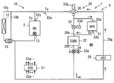
- a system 1 provides an apparatus that handles a coolant that exchanges heat with an engine 2 (internal combustion engine).
- the system 1 provides an engine temperature control device.
- the coolant is water, ethylene glycol or a mixture thereof.
- the system 1 releases waste heat of the engine 2 as a heat source (HS) to the atmosphere by means of a coolant, and adjusts the temperature of the engine 2.
- the temperature of the engine 2 is adjusted by the coolant.
- the system 1 exchanges heat between the coolant and the device 3.
- the device 3 has passive devices that are cooled or heated by the coolant and active devices that can heat the coolant.
- the system 1 is mounted on a vehicle.
- the system 1 can be applied to a vehicle, an aircraft, a ship, and a ground-mounted engine using device.
- Passive devices are devices 3 that are preferably temperature controlled.
- a typical example of a passive device is provided by an EGR cooler (EGRC) 22 described below.
- the device 3 is a device which exhibits its function even with a coolant heated by the engine 2 but heating is desirable when the temperature of the engine 2 is low.
- the EGRC 22 is also called a high temperature device.
- the device 3 includes a plurality of examples described later.
- the device 3 controls, for example, an EGR cooler (EGRC) that adjusts the temperature of the EGR gas, a heater core (HTC) for heating, an exhaust heat recovery unit (EHR) that recovers heat from the exhaust of the engine 2, and an amount of EGR gas
- EGRV EGR valve
- THRB throttle body
- the EGRC 22 is called a main device.
- HTC, EHR, EGRV, THRB are called additional equipment.
- the device 3 is also a device that assists the operation of the engine 2.
- the active device is an auxiliary heat source (AHS) as a heat source replacing the engine 2.
- the auxiliary heat source can raise the temperature of the coolant instead of the engine 2.
- the auxiliary heat source includes at least one of a heat accumulator that stores the heat of the coolant, or an apparatus that generates waste heat.
- the coolant of the engine 2 is stored in the auxiliary heat source 21.
- the heat storage can be provided by storing the high temperature coolant itself or by storing heat in a heat storage material capable of switching between heat storage and heat release by a chemical reaction.
- the devices that generate waste heat are devices other than the engine 2.
- the device that generates waste heat can include at least one of a device including an electronic circuit (for example, an inverter circuit), a battery device, an electric heater device, an exhaust heat recovery device, and the like.
- the system 1 provides at least a function of cooling the engine 2, a function of adjusting the temperature of the passive device by the coolant, and a function of warming the passive device by the active device.
- System 1 may provide the ability to warm engine 2 with active equipment.
- the terms cold, cold, low temperature, and the like in relation to the temperature of the coolant refer to, for example, 20 ° C. or less.
- the terms such as warm, warm, and high temperature with respect to the temperature of the coolant indicate 60 ° C. or higher, preferably 80 ° C. or higher.
- the term warm-up refers to the process of transitioning to a temperature higher than the initial temperature.
- the term warm-up as an example, means a temperature rise from 0 ° C. in winter, typically from 0 ° C. to 60 ° C. or more.
- the system 1 comprises a cooling system 10 for the engine 2 and an auxiliary system 20 for temperature regulation of the device 3.
- the cooling system 10 regulates the temperature of the engine 2.
- the cooling system 10 cools the engine 2.
- the cooling system 10 circulates a coolant that exchanges heat with the engine 2.
- the auxiliary system 20 is a system that assists the cooling system 10.
- the auxiliary system 20 assists the cooling system 10 by providing a warm-up process that warms the engine 2 if the temperature of the engine 2 is too low.
- Auxiliary system 20 is also an additional system that utilizes a coolant.
- the auxiliary system 20 regulates the temperature of the device 3 that assists the engine 2. Control of the temperature of the device 3 includes both cooling to lower the temperature of the device 3 by the coolant and heating to raise the temperature of the device 3 by the coolant.
- the auxiliary system 20 provides both temperature control of the engine 2 and temperature control of the equipment 3.
- the cooling system 10 includes a radiator 12 that provides heat exchange between the coolant and the ambient air.
- the radiator 12 dissipates the waste heat of the engine 2 to the atmosphere.
- the engine 2 and the radiator 12 form a heat radiation passage 10a through which the coolant circulates.
- the cooling system 10 has a built-in pump 13 built in the engine 2.
- the built-in pump 13 is driven by the engine 2.
- the built-in pump 13 may be driven by a motor.
- the built-in pump 13 sends the coolant in the forward direction to the heat release passage 10a.
- the built-in pump 13 continues to deliver the coolant while the engine 2 is operating by combustion.
- the cooling system 10 may be configured without the built-in pump 13.
- the cooling system 10 has an electric pump 14.
- the electric pump 14 is driven by a motor 53c.
- the electric pump 14 sends the coolant in the forward direction to the heat radiation passage 10a.
- the electric pump 14 is located between the engine 2 and the radiator 12.
- the electric pump 14 is located between a thermostat valve 15 described later and the engine 2.
- the electric pump 14 also belongs to a warm-up circulation passage WR described later.
- the built-in pump 13 and the electric pump 14 can be provided to the cooling system 10 by an existing pump.
- the cooling system 10 has a thermostat valve 15.
- the thermostat valve 15 regulates the amount of coolant flowing through the radiator 12 in response to the temperature of the coolant.
- the thermostat valve 15 is provided by an electrically controllable solenoid valve or a valve opened and closed by a thermostat.
- the thermostat valve 15 can open and close the heat radiation passage 10a in response to the temperature of the coolant.
- the thermostat valve 15 can shut off the coolant flowing through the radiator 12 when the temperature of the coolant is lower than a predetermined temperature.
- the thermostat valve 15 regulates the temperature of the coolant to be above the lower limit temperature and below the upper limit temperature. When the temperature of the engine 2 falls below the lower limit temperature, the thermostat valve 15 reduces the flow rate of the radiator 12 or shuts it down to warm up the engine 2.
- the cooling system 10 has a heat radiation passage 10 a through which the coolant flows through both the engine 2 and the radiator 12.
- the heat radiation passage 10 a passes through the engine 2, exits the engine 2, passes through the radiator 12, and returns to the engine 2 again.
- the heat radiation passage 10 a flows the coolant in the order of the engine 2, the radiator 12, the thermostat valve 15, the electric pump 14, the built-in pump 13, and the engine 2.
- the auxiliary system 20 has an auxiliary heat source 21.
- the auxiliary heat source 21 warms the coolant when all or part of the system 1 is cold.
- the warm coolant warms the engine 2 and / or the equipment 3.
- the function of warming the engine 2 and / or the device 3 is called warm-up.
- the auxiliary heat source 21 is also called a heat accumulator.
- the heat accumulator stores the high temperature coolant in the normal operating condition after the engine 2 reaches the normal temperature of 80 ° C. or higher.
- the regenerator supplies high temperature coolant to the system 1 when all or part of the system 1 is low temperature.
- the heat accumulator warms up the engine 2 and / or the device 3 by warming the coolant.
- the auxiliary system 20 has an EGRC 22 (EGR cooler).
- the EGRC 22 regulates the temperature of the EGR gas returned from the exhaust system to the intake system.
- the EGRC 22 cools the EGR gas in the normal operation state of the engine 2.
- the EGRC 22 is preferably warmed or warmed up when the temperature of the EGRC 22 itself is low enough to cause condensation on the EGR gas.
- the auxiliary system 20 has a coolant control valve (hereinafter referred to as a CCV) 31 that controls fluid communication of a passage between the engine 2 and the auxiliary system 20.
- the CCV 31 is provided by an on-off valve or a flow control valve.
- the CCV 31 is provided between the engine 2 and the auxiliary system 20.
- the CCV 31 is disposed at the outlet of the coolant from the engine 2.
- the CCV 31 has an electromagnetic actuator 53 a for driving the CCV 31.
- the CCV 31 opens and closes at least the passage.
- the CCV 31 may allow slight fluid communication even in the closed state.
- the CCV 31 may not be completely closed.
- the thermostat valve 15 closes the heat release passage 10 a and the CCV 31 is controlled to be in the valve closed state, whereby circulation of the coolant flowing in the engine 2 can be stopped.
- Such a fluid stop control mode is provided when the engine 2 is warmed up.
- the fluid stop control mode contributes to quick warm-up of the engine 2.
- the auxiliary system 20 has a passage switching mechanism for controlling the auxiliary heat source 21.
- the passage switching mechanism switches whether or not the coolant is to be heated by at least the auxiliary heat source 21. Furthermore, the passage switching mechanism switches whether to transfer the heat of the auxiliary heat source 21 to the EGRC 22 via the coolant.
- the passage switching mechanism switches whether to place the auxiliary heat source 21 and the EGRC 22 in a closed circuit not including the engine 2 or in a closed circuit including the engine 2.
- a passage switching mechanism can be provided by one or more control valves and a passage.
- the passage switching mechanism is also called a valve mechanism.
- the passage switching mechanism can be provided by a three-way valve (hereinafter referred to as TWV) 32 provided in a branch portion or a junction portion of a passage for the coolant to switch the flow passage.
- the TWV 32 provides at least two modes including flowing the cooling fluid through the auxiliary heat source 21 and not flowing the cooling fluid to the auxiliary heat source 21.
- the communication state of the TWV 32 can be switched by an electromagnetic actuator 53b.
- the auxiliary system 20 has an auxiliary passage 20 a for the coolant that the coolant flows through both the engine 2 and the supplemental heat source 21.
- the cooling system 10 and the auxiliary system 20 are arranged in parallel to the engine 2.
- the bifurcations can be provided by a gallery in the tee or engine 2 as illustrated in FIG. The same applies to their confluences.
- the auxiliary passage 20 a provides a heat storage mode for storing heat in the auxiliary heat source 21 and a heat release mode for releasing the heat of the auxiliary heat source 21.
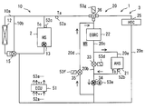
- the auxiliary passage 20a provides a closed circuit from the engine 2 through the CCV 31, through the TWV 32, through the auxiliary heat source 21, through the EGRC 22, through the electric pump 14, and back to the engine 2.
- the auxiliary passage 20 a is an annular passage including the engine 2 and the auxiliary heat source 21.
- the auxiliary passage 20a includes a plurality of pipelines.
- the auxiliary system 20 has an auxiliary bypass passage 20b.
- the auxiliary bypass passage 20 b allows the coolant to flow from the upstream side to the downstream side of the auxiliary heat source 21 without flowing through the auxiliary heat source 21.
- the auxiliary bypass passage 20b is also referred to as a nullifying passage that nullifies part or all of the heating by the auxiliary heat source 21.
- the auxiliary bypass passage 20 b branches from the TWV 32 and joins the auxiliary passage 20 a between the auxiliary heat source 21 and the EGRC 22. In other words, the TWV 32 is provided at a branch portion where the auxiliary bypass passage 20b branches from the auxiliary passage 20a.
- the auxiliary system 20 has an equipment passage 20 c through which the coolant flows through the EGRC 22.
- An EGRC 22 is disposed in the device passage 20c.
- the equipment passage 20 c supplies the coolant used in the EGRC 22 to the EGRC 22.
- the device passage 20c is a part of the auxiliary passage 20a.
- the device passage 20 c is provided downstream of the auxiliary heat source 21.
- the device passage 20c is located downstream of the junction of the auxiliary passage 20a and the auxiliary bypass passage 20b.
- the EGRC 22 is one of the devices 3 temperature-controlled by the coolant supplied from the auxiliary passage 20a.
- the auxiliary system 20 has an engine bypass passage 20d.
- the engine bypass passage 20 d allows either the whole coolant to flow through the EGRC 22 without flowing through the engine 2 or allows a part of the coolant to flow through the engine 2 and the remaining part of the coolant to flow through the EGRC 22.
- the engine bypass passage 20d allows a circulating flow of coolant not passing through the engine 2 at all. Note that part of the coolant is a limited amount. Some of the coolant may be less than the remainder of the coolant.
- the engine bypass passage 20 d branches from between the electric pump 14 and the engine 2 and joins the auxiliary passage 20 a downstream of the CCV 31.
- the engine bypass passage 20 d provides a path for bypassing the engine 2 in the auxiliary system 20.
- the engine bypass passage 20 d provides a path for bypassing the engine 2 as viewed from the auxiliary heat source 21.
- the engine bypass passage 20 d can form a closed circuit passing through both the auxiliary heat source 21 and the EGRC 22 without passing through the engine 2.
- This closed circuit is also referred to as a warm-up circulation passage WR.
- the warm-up circulation passage WR is formed in the auxiliary passage 20a.
- the warm-up circulation passage WR provides a closed circuit for the coolant passing through the auxiliary heat source 21 and the EGRC 22 which is one of the devices.
- the warm-up circulation passage WR provides a closed circuit for the coolant that does not pass through the engine 2. Part or all of the coolant can flow through the warm circulation passage. A part or all of the coolant flows through the auxiliary heat source 21 and the EGRC 22 without flowing through the internal passage of the engine 2.
- the warm-up circulation passage WR supplies part or all of the coolant whose temperature has been increased by the auxiliary heat source 21 to the EGRC 22 without supplying it to the engine 2. As a result, the amount of the coolant flowing through the engine 2 is suppressed to be smaller than the amount of the coolant flowing through the auxiliary heat source 21.
- the mode of low suppression includes the case where the amount of coolant flowing through the engine 2 is zero (0).
- the warm-up circulation passage WR includes the auxiliary heat source 21 and the EGRC 22 and allows the circulating flow of the coolant not including the engine 2.
- the warm-up circulation passage WR includes the auxiliary heat source 21 and the EGRC 22, by providing a closed circuit that does not include the engine 2, the amount of coolant flowing through the engine 2 rather than the amount of coolant flowing through the auxiliary heat source 21 At least suppress.
- the warm-up circulation passage WR provides a passage through the auxiliary heat source 21 and the EGRC 22 without passing through the engine 2. By providing this passage, part or all of the coolant whose temperature has been raised by the auxiliary heat source 21 can be supplied to the device 3 (EGRC 22) without being supplied to the engine 2.
- the warm-up circulation passage WR supplies part or all of the coolant whose temperature has been increased by the auxiliary heat source 21 to the EGRC 22 without supplying it to the engine 2.
- the CCV 31 may be completely closed. In this case, the warm-up circulation passage WR supplies the coolant whose temperature has been increased by the auxiliary heat source 21 to the EGRC 22 without supplying the coolant to the engine 2. In this case, the adverse effect due to the low temperature of the engine 2 is avoided.
- the CCV 31 may not be completely closed. In this case, the warm-up circulation passage WR supplies a part of the coolant whose temperature has been increased by the auxiliary heat source 21 to the engine 2, and supplies the remaining part of the coolant to the EGRC 22. In this case, the adverse effect resulting from the low temperature of the engine 2 is suppressed.
- the electric pump 14 is provided in a passage common to the cooling system 10 and the auxiliary system 20.
- the electric pump 14 is located downstream of a junction where the auxiliary passage 20a joins the heat radiation passage 10a.
- the electric pump 14 is located upstream of a branch portion where the engine bypass passage 20b branches from the heat radiation passage 10a.
- the auxiliary passage 20a joins on the upstream side of the electric pump 14, and the engine bypass passage 20d extends from the downstream side of the electric pump 14.
- the system 1 has a control unit (ECU) 51.
- the control device 51 is an electronic control unit.
- the control device has at least one arithmetic processing unit (CPU) and at least one memory device (MMR) as a storage medium for storing programs and data.
- the control device 51 is provided by a microcomputer provided with a computer readable storage medium.
- a storage medium is a non-transitory tangible storage medium which non-temporarily stores a computer readable program.
- the storage medium may be provided by semiconductor memory or a magnetic disk or the like.
- the controller 51 may be provided by one computer or a set of computer resources linked by a data communication device.
- the program is executed by the control device 51 to cause the control device 51 to function as the device described in this specification and causes the control device 51 to perform the method described in this specification.
- the control system includes, as input devices, a plurality of signal sources that supply signals indicating information input to the control device 51.
- the control system acquires information by the control device 51 storing the information in the memory device.
- the control system has a plurality of controlled objects whose behavior is controlled by the control device 51 as output devices.
- the control system controls the behavior of the controlled object by converting the information stored in the memory device into a signal and supplying the signal to the controlled object.
- the control device 51 included in the control system, the signal source and the control object provide various elements. At least some of these elements can be referred to as blocks for performing the function. In another aspect, at least some of those elements can be referred to as modules or sections that are interpreted as a configuration. Furthermore, the elements included in the control system can also be referred to as means for realizing that function only when intentional.
- a signal source is provided by a plurality of temperature sensors 52a, 52b, 52c.
- the controlled object is provided by a plurality of actuators 53a, 53b and a motor 53c.
- the means and / or function provided by the control system may be provided by software stored in a tangible memory device and a computer executing the same, only software, only hardware, or a combination thereof.
- the controller 51 when the controller 51 is provided by an electronic circuit that is hardware, it can be provided by a digital circuit or analog circuit that includes a number of logic circuits.
- a basic cooling system 10 is provided to adjust the temperature of the engine 2.
- An auxiliary system 20 is provided that utilizes engine 2 coolant to adjust the temperature of the EGRC 22, such as an EGR cooler.
- An auxiliary system 20 is provided to supply the heat of the auxiliary heat source 21 to the EGRC 22 in order to assist the warm-up of the EGRC 22.
- a warming up circulation passage WR which passes through the auxiliary heat source 21 and the EGRC 22 and does not pass through the engine 2 is provided.
- the warm-up circulation passage WR suppresses a phenomenon in which the heat of the auxiliary heat source 21 is taken by the engine 2.
- Warm-up of the engine 2 is mainly realized by the heat generation of the engine 2 itself.
- an auxiliary system 20 may be provided which supplies the heat of the auxiliary heat source 21 to the engine 2.
- the auxiliary heat source 21 is a heat accumulator
- an auxiliary system 20 capable of storing heat for the next warm-up using the coolant of the engine 2 is provided.
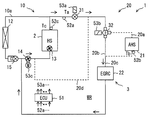
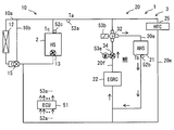
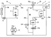
- FIG. 2 shows the flow of the coolant in the normal mode.
- the broken line indicates a passage through which the coolant above the leak flow rate does not flow.
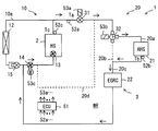
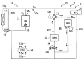
- FIG. 3 shows the flow of the coolant in the heat storage mode.
- the heat storage mode is executed.
- the electric pump 14 is in the operating state
- the CCV 31 is in the valve opening state
- the TWV 32 supplies the cooling fluid to the auxiliary heat source 21.
- the coolant of the engine 2 is stored in the auxiliary heat source 21.
- the coolant flowing into the device passage 20c regulates the temperature of the EGRC 22.
- the warm-up of the EGRC 22 progresses simultaneously.
- the warm-up of the EGRC 22 is performed by the heat supplied from the engine 2 and the heat supplied from the auxiliary heat source 21.
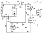
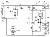
- FIG. 4 shows the flow of the coolant in the equipment warm-up mode.
- the equipment warm-up mode is provided when only the EGRC 22 is warmed up.
- the electric pump 14 is in the operating state
- the CCV 31 is in the valve closing state
- the TWV 32 supplies the coolant to the auxiliary heat source 21. Since the CCV 31 is closed, the coolant passes from the electric pump 14 through the engine bypass passage 20 d and reaches the downstream of the CCV 31. That is, the coolant circulates only in the auxiliary system 20.
- the coolant flows through the TWV 32, the auxiliary heat source 21, the EGRC 22, the electric pump 14, and the engine bypass passage 20d.
- the coolant circulates in the warm-up circulation passage WR.
- the coolant does not pass through the engine 2. Therefore, the heat of the auxiliary heat source 21 can be supplied to the EGRC 22 without being taken by the engine 2.
- the EGRC 22 is an EGR cooler
- the temperature of the EGR cooler can be quickly warmed. As a result, dew condensation caused by the low temperature EGR cooler can be suppressed.
- EGR gas can be supplied from the beginning when the engine 2 is started.
- FIG. 5 shows the flow of the coolant in the engine warm-up mode.
- This mode is provided when it is not necessary to warm up the EGRC 22.
- the electric pump 14 is in the operating state
- the CCV 31 is in the valve closing state
- the TWV 32 supplies the coolant to the auxiliary bypass passage 20b.
- the temperature of the engine 2 is warmed up or adjusted by the cooling system 10 and the temperature of the EGRC 22 is adjusted by the cooling fluid, a state in which the cooling fluid does not pass through the auxiliary heat source 21 can be realized.
- This mode can be used, for example, in an intermediate temperature zone that does not require the EGRC 22 to be warmed up.
- FIG. 6 shows detection values of the temperature sensors 52a, 52b, 52c and thresholds of a plurality of determination processes in the control device 51.
- These thresholds can have values, for example, as in Example 1 (Ex. 1) or Example 2 (Ex. 2).
- the unit is in degrees Celsius.
- the detected value and the symbol of the threshold are used in the flowchart described later.
- the engine warm-up completion temperature T1 is higher than the EGR cooler warm-up completion temperature T2 e (T1> T2 e). Thereby, in the normal operation, the warm-up of the EGRC 22 is completed first, and the warm-up of the engine 2 is completed later. However, in special driving, it may be reversed.
- the EGR cooler warm-up start temperature T2s is lower than the EGR cooler warm-up completion temperature T2e (T2s ⁇ T2e).
- the EGR cooler warm-up start temperature T2s sets a condition of extremely low temperature. Thereby, at the cryogenic temperature, the warm-up of the engine 2 is performed but the warm-up of the EGRC 22 is not performed.
- the heat storage amount determination temperature T3 provides a threshold for determining whether the heat provided by the auxiliary heat source 21 is sufficient to warm up the EGRC 22.
- the heat release completion temperature T4 sets the lower limit at which the heat from the auxiliary heat source 21 can be used. In this embodiment, the heat release completion temperature T4 is equal to the EGR cooler warm up completion temperature T2e.
- the heat storage start temperature T5 indicates that the engine 2 has sufficiently warmed the coolant.
- the heat storage start temperature T5 is also a temperature at which the heat storage state can be maintained for a long time.
- the TWV 32 is also referred to as a three-port multi-position valve.
- mode A and mode B are used.
- the TWV 32 communicates the port Pa with the port Pc.
- the coolant flows to the auxiliary bypass passage 20b without flowing to the auxiliary heat source 21.
- the TWV 32 communicates the port Pa with the port Pb.
- the coolant flows to the auxiliary heat source 21 and does not flow to the auxiliary bypass passage 20b.
- mode C the TWV 32 communicates the port Pb with the port Pc.
- mode D the TWV 32 communicates all of the port Pa, the port Pb, and the port Pc.
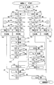
- FIGS. 8, 9, 10, and 11 show control related to the auxiliary system 20.
- the control is performed by the controller 51.
- the control starts with the powering on of the system 1 before the engine 2 is started.
- step 161 the engine outlet coolant temperature Ta (hereinafter referred to as temperature Ta) detected by the temperature sensors 52a and 52b and the heat accumulator outlet coolant temperature Tb (hereinafter referred to as temperature Tb) are acquired. .
- step 162 it is determined whether or not temperature Ta ⁇ threshold T1.
- the threshold T1 is an engine warm-up completion temperature. When the temperature Ta is lower than the threshold T1, the engine 2 needs to be warmed up. If the temperature Ta is not lower than the threshold T1, the engine 2 need not be warmed up. Thus, step 162 provides a determination unit that determines whether the engine 2 needs to be warmed up.
- step 163 the CCV 31 is controlled to the valve closing state. Thereby, utilization of the cooling water of the engine 2 is stopped, and the engine 2 is warmed up by the cooling system 10.
- step 164 it is determined whether or not the temperature Ta ⁇ the threshold T2e.
- the threshold T2e is the EGR cooler warm-up completion temperature. If the temperature Ta is lower than the threshold T2e, the EGRC 22 needs to be warmed up. If the temperature Ta is not lower than the threshold T2e, the EGRC 22 need not be warmed up. Here, the necessity of warm-up of the EGRC 22 is determined by the temperature Ta. Step 164 provides a determination unit that determines whether the EGRC 22 needs to be warmed up.
- step 165 it is determined whether or not temperature Ta ⁇ ⁇ threshold value T2s.
- the threshold T2s is the EGR cooler warm-up start temperature. If the temperature Ta is lower than the threshold T2s, the temperature of the EGRC 22 is too low. When the temperature Ta is equal to or higher than the threshold value T2s, the EGRC 22 is a temperature that can be warmed up. Step 165 provides a determination unit that determines whether the EGRC 22 can be warmed up.
- step 166 it is determined whether or not temperature Tb 3 T3.
- the threshold T3 is a heat storage amount determination temperature. If the temperature Tb is lower than the threshold T3, the heat that can be supplied from the auxiliary heat source 21 is not sufficient. When the temperature Tb is equal to or higher than the threshold T3, the auxiliary heat source 21 can supply sufficient heat. Step 166 provides a determination unit that determines whether the auxiliary heat source 21 can supply the amount of heat for warming up the EGRC 22.
- step 167 the TWV 32 is controlled to mode A. At this time, the system 1 is in the engine warm-up mode shown in FIG. In this case, the auxiliary heat source 21 is not used.
- step 168 the engine 2 is started. At the same time, the built-in pump 13 and the electric pump 14 are started.
- step 169 an engine coolant temperature Tc (hereinafter referred to as a temperature Tc) is acquired.
- Tc an engine coolant temperature
- the CCV 31 since the CCV 31 is in the valve closed state, the temperature of the coolant inside the engine 2 can be obtained by a temperature sensor inside the engine 2 or estimation processing.
- the contents of Patent Document 1 or Patent Document 2 can be incorporated by reference.
- step 170 it is determined whether or not temperature Tc ⁇ T1. If the temperature Tc is lower than the threshold T1, further warming up of the engine 2 is necessary. If the temperature Tc is not lower than the threshold T1, the engine 2 need not be warmed up. Therefore, step 170 provides a determination unit that determines whether the engine 2 needs to be warmed up. The process of step 169 and step 170 is repeated to warm up the engine 2.
- the CCV 31 is controlled to the valve open state. Thus, the system 1 shifts to the normal mode shown in FIG.
- the warm-up of the EGRC 22 is realized solely by the heat that it receives from the EGR gas. In other words, the engine 2 can be warmed up without specially warming up the EGRC 22.
- the loop of steps 169-170 provides an engine warm-up V which warms up the engine 2.
- step 172 is performed.
- the TWV 32 is controlled to mode B.
- the system 1 is in the device warm-up mode shown in FIG. In this case, the auxiliary heat source 21 is used.
- the engine 2 is started.
- the built-in pump 13 and the electric pump 14 are started.
- the warm-up of the engine 2 proceeds.
- warming up of the EGRC 22 proceeds using the auxiliary heat source 21.
- the auxiliary heat source 21 is disposed immediately upstream of the EGRC 22. Therefore, the heat of the auxiliary heat source 21 is efficiently transmitted to the EGRC 22. Further, in the device warm-up mode, the coolant flows cyclically through the warm-up circulation passage WR without flowing through the engine 2. Therefore, the heat of the auxiliary heat source 21 is less likely to be taken away by the engine 2 having a relatively large heat capacity. Therefore, the heat of the auxiliary heat source 21 can be effectively used to warm up the EGRC 22.
- the temperature Tc is obtained.
- the temperature Tb is obtained.
- the threshold value T4 is a heat radiation completion temperature. If all the steps 176-178 are answered in the affirmative, the process of steps 174-178 is repeated. Here, both warm-up of the engine 2 and warm-up of the EGRC 22 by the auxiliary heat source 21 proceed. The loop of steps 174-178 provides a supplemental warm-up IV utilizing the supplemental heat source 21.
- step 180 the CCV 31 is controlled to be open. Thereby, the heat generated by the engine 2 is supplied to the auxiliary system 20. In other words, the system 1 shifts to the heat storage mode shown in FIG.
- step 181 the temperature Ta and the temperature Tb are acquired.
- step 182 it is determined whether the temperature Ta ⁇ T2e.
- the necessity of warm-up of the EGRC 22 is determined by the temperature Ta.
- step 183 it is determined whether or not temperature Tb T T4.
- the loop of steps 181-183 provides a heat storage section III that stores heat in the auxiliary heat source 21.
- step 184 the TWV 32 is controlled to mode A. That is, the warming up of the EGRC 22 by the auxiliary heat source 21 ends.
- step 177 is a process of indirectly determining that the warm-up of the EGRC 22 is completed based on the temperature Tc.
- step 178 is a process of determining that the heat of the auxiliary heat source 21 has become insufficient.
- step 179 the TWV 32 is controlled to mode A. That is, the warming up of the EGRC 22 by the auxiliary heat source 21 ends. Thereafter, the process proceeds to step 169, where warm-up of the engine 2 in the engine warm-up mode is continued.
- step 185 the CCV 31 is controlled to be in an open state. Steps 186-188 provide the same processing as steps 164-166, respectively. If all of steps 186-188 are answered in the affirmative, then the procedure proceeds to step 189.
- step 189 the TWV 32 is controlled to mode B. At this time, the system 1 is in the heat storage mode shown in FIG. In this case, the auxiliary heat source 21 is used.
- step 190 the engine 2 is started. At the same time, the built-in pump 13 and the electric pump 14 are started. As a result, warm-up of the engine 2 also proceeds. After step 190, the process proceeds to step 181.
- step 191 the TWV 32 is controlled to mode A. At this time, the system 1 is in the normal mode shown in FIG. In this case, the auxiliary heat source 21 is not used.
- step 192 the engine 2 is started. At the same time, the built-in pump 13 and the electric pump 14 are started. The processing through step 192 provides a normal processing unit II that does not utilize the auxiliary heat source 21.
- step 165 if a negative determination is made in step 165, the processing proceeds to step 261 of FIG. 9 via connection step C. If the temperature Ta is lower than the threshold T2e and lower than the threshold T2s, it is considered that the EGRC 22 needs to be warmed up but the temperature of the EGRC 22 is too low.
- step 261 the TWV 32 is controlled to mode A.
- step 262 the engine 2 is started, and at the same time, the built-in pump 13 and the electric pump 14 are started.
- step 263 the temperature Tc is obtained.
- step 264 it is determined whether or not temperature Tc ⁇ threshold value T1.
- step 265 it is determined whether or not temperature Tc ⁇ threshold value T2s.
- steps 264-265 are answered in the affirmative, repeat steps 263-265. In this case, it can be determined that the internal temperature of the engine 2 and the temperature of the EGRC 22 are too low. At this time, the system 1 is in the engine warm-up mode shown in FIG.
- step 265 the temperature Tc becomes equal to or higher than the threshold T2s.
- step 266 the TWV 32 is controlled to mode B.
- Steps 267-271 provide the same processing as steps 174-178, respectively. If all steps 269-271 are answered in the affirmative, repeat steps 267-271.
- both warm-up of the engine 2 and warm-up of the EGRC 22 by the auxiliary heat source 21 proceed.
- step 272 When the warm-up of engine 2 proceeds and is negatively determined in step 269, the process branches to step 272.
- Steps 272-276 provide the same processing as steps 180-184, respectively.
- steps 273-275 system 1 is in the thermal storage mode shown in FIG.
- step 276 the TWV 32 is controlled to mode A. That is, the warming up of the EGRC 22 by the auxiliary heat source 21 ends.
- step 270 or step 271 determines whether the determination in step 270 or step 271 is negative. If the determination in step 270 or step 271 is negative, the process proceeds to step 277. At this time, the system 1 is in the engine warm-up mode shown in FIG. Steps 277-280 provide the same processing as steps 179 and 169-171, respectively.
- step 281 the CCV 31 is controlled to the valve open state. At this time, the system 1 is in the normal mode shown in FIG.
- step 282 the temperature Ta is obtained.
- step 283 it is determined whether or not temperature Ta ⁇ threshold T2s. If the determination at step 283 is affirmative, the steps 282 to 283 are repeated. In this case, it can be determined that the outlet temperature of the engine 2 is too low.
- step 284 the TWV 32 is controlled to mode B. Thereby, it transfers to the apparatus warming-up mode shown in FIG. 4 from the normal mode shown in FIG. After step 284, the process proceeds to step 273.
- step 187 if a negative determination is made in step 187, the processing proceeds to step 361 of FIG. 10 via connection step D.
- step 361 the TWV 32 is controlled to mode A.
- step 362 the engine 2 is started, and at the same time, the built-in pump 13 and the electric pump 14 are started.
- step 363 the temperature Ta is obtained.
- step 364 it is determined whether or not the temperature Ta ⁇ the threshold T 2 s. If the determination in step 364 is affirmative, the steps 363 to 264 are repeated. At this time, the system 1 is in the normal mode shown in FIG.
- step 365 the TWV 32 is controlled to mode B. Thereby, it transfers to the thermal storage mode shown in FIG. 3 from the normal mode shown in FIG. Steps 365-369 provide the same processing as steps 284, 273-276, respectively.
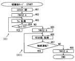
- FIG. 11 shows a post-warmup mode performed after the warm-up mode shown in FIGS. 8, 9 and 10.
- the CCV 31 is controlled to be in the valve opening state.
- the CCV 31 is a normally open type.
- the TWV 32 is controlled to mode A.
- the TWV 32 is in mode A when there is no control from the actuator 53b.
- the temperature Ta is obtained.
- the threshold T5 is a heat storage start temperature. If the temperature Ta is lower than the threshold T5, the steps 463 to 464 are repeated. At this time, the system 1 is in the normal mode shown in FIG. When the temperature Ta becomes equal to or higher than the threshold T5 in step 464, the process branches to step 465.
- step 465 the TWV 32 is controlled to mode B.
- the system 1 shifts to the heat storage mode shown in FIG.
- step 466 the state of the engine 2 which is the heat source HS is acquired.
- a signal indicating whether the engine 2 is continuously operated is obtained. For example, the number of revolutions of the engine 2, the ignition switch on or off, and the speed indicating the traveling of the vehicle are acquired.
- step 467 it is determined whether the engine 2 is continuously operated. If the engine 2 is continuously operated, repeat steps 466-467. Thereby, the waste heat from the engine 2 is stored in the auxiliary heat source 21. Further, when the engine 2 is restarted, the heat of the auxiliary heat source 21 can be used to warm up the EGRC 22.
- step 468 the TWV 32 is controlled to mode A. As a result, the coolant does not pass to the auxiliary heat source 21, and the heat stored in the auxiliary heat source 21 is maintained.
- the passage switching mechanism is provided by the TWV 32.
- the passage switching mechanism may be provided by the on-off valve 33.
- an on-off valve 33 is provided in the auxiliary bypass passage 20 b instead of the TWV 32.
- the on-off valve 33 is opened and closed by an electromagnetic actuator 53 d controlled by the control device 51.
- the passage switching mechanism of this embodiment can be used as an alternative configuration to the other embodiments. Also in this embodiment, the same effect as that of the preceding embodiment can be obtained.
- This embodiment is a modification based on the preceding embodiment.
- the EGRC 22 is disposed downstream of the auxiliary heat source 21.
- the device may be disposed upstream of the auxiliary heat source 21.
- the EGRC 22 is disposed upstream of the auxiliary heat source 21 in the coolant passage in the auxiliary system 20. Also in this configuration, the auxiliary heat source 21 and the EGRC 22 are located in the warm-up circulation passage WR. When the coolant circulates in the warm-up circulation passage WR, the position of the EGRC 22 is also downstream of the auxiliary heat source 21. Since the warm-up circulation passage WR does not include the engine 2, the heat of the auxiliary heat source 21 can be efficiently transmitted to the EGRC 22.
- the arrangement of this embodiment is available as an alternative to the other embodiments. Also in this embodiment, the same effect as that of the preceding embodiment can be obtained.
- the device 3 using the coolant is provided by the EGRC 22.
- the device 3 may be provided by another device.
- the device 3 may also include a plurality of devices.
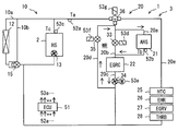
- the device 3 includes an EGRC 422, an HTC 25, an EHR 26, an EGRV 27 and a THRB 28.
- the EGRC 422 has a branched coolant passage inside.
- the EGRC 422 has one inlet, an intermediate outlet, and an end outlet.
- the HTC 25 and the EHR 26 are provided in series in one passage extending from the middle outlet of the EGRC 422.
- an EGRV 27 and a THRB 28 are provided in series.
- the plurality of devices 3 can be interchanged in arrangement. Some or all of the plurality of devices 3 of this embodiment can be used as an alternative configuration of the other embodiments. Also in this embodiment, the same effect as that of the preceding embodiment can be obtained.
- the warm-up circulation passage WR is formed by the engine bypass passage 20d.
- the warm-up circulation passage WR may be formed by arranging the device 3 to be warmed up and the auxiliary heat source 21 in parallel.
- the cooling system 10 has a radiator bypass passage 10 b in which the coolant flows through the engine 2 but does not flow through the radiator 12.
- the thermostat valve 15 switches between the heat radiation passage 10a and the radiator bypass passage 10b. When the temperature of the coolant is higher than the upper limit temperature, the thermostat valve 15 causes the coolant to flow through the heat dissipation passage 10a. The thermostat valve 15 allows the coolant to flow to the radiator bypass passage 10b when the temperature of the coolant is lower than the lower limit temperature. The thermostat valve 15 opens and closes the radiator bypass passage 10b.
- the thermostat valve 15 can be disposed upstream or downstream of the radiator 12. In this embodiment, the coolant passes through the engine 2 by the built-in pump 13 while the engine 2 is in operation.
- the auxiliary system 20 has an auxiliary passage 20 a that exits the engine 2, passes through the auxiliary heat source 21, and returns to the engine 2.
- the auxiliary system 20 has an auxiliary parallel passage 20 f parallel to the auxiliary heat source 21.
- the auxiliary parallel passage 20 f connects the upstream side and the downstream side of the auxiliary heat source 21 without passing through the engine 2. Therefore, the auxiliary parallel passage 20 f apparently bypasses the auxiliary heat source 21.
- the auxiliary parallel passage 20f is also the device passage 20c.
- the device passage 20c is also referred to as a first device passage.
- auxiliary parallel passage 20 f forms a warm-up circulation passage WR passing through the auxiliary heat source 21 and the EGRC 22 without passing through the engine 2.
- the auxiliary parallel passage 20f is also the engine bypass passage 20d.
- the warm-up circulation passage WR has an auxiliary parallel passage 20f in which the EGRC 22 is disposed and providing the engine bypass passage 20d.
- the auxiliary parallel passage 20f is also referred to as an auxiliary reverse flow passage in which the flow direction of the coolant is reversed.
- the flow direction of the cooling fluid in the auxiliary parallel passage 20 f is reversed in the case of flowing the cooling fluid to the engine 2 and the EGRC 22 and in the case of flowing the cooling fluid to the auxiliary heat source 21 and the EGRC 22.
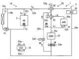
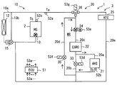
- the auxiliary system 20 has a second equipment passage 20 e through the HTC 25.
- the HTC 25 is one of the additional devices whose temperature is controlled by the coolant supplied from the auxiliary passage.
- the auxiliary system 20 includes a second device passage 20 e in which additional devices other than the EGRC 22 are disposed.
- the second device passage 20e is positioned in parallel with a part of the auxiliary passage 20a.
- the second device passage 20e branches from the auxiliary passage 20a and merges with the auxiliary passage 20a again.
- the second device passage 20 e exits the engine 2, passes through the HTC 25, and returns to the engine 2.
- the warm-up circulation passage WR is formed without sharing the passage with the second device passage 20e, in other words, the passages do not overlap in the flow direction. Thus, a difference is allowed between the temperature of the coolant flowing through the warm-up circulation passage WR and the temperature of the coolant flowing through the second device passage 20e.
- the passage switching mechanism is provided by the TWV 32.
- the TWV 32 is provided at a branch portion between the auxiliary passage 20a and the auxiliary bypass passage 20b, which are separated from the branch portion between the auxiliary passage 20a and the second device passage 20e.
- the TWV 32 can provide the illustrated mode C in the equipment warm-up mode.
- An electric pump 34 is provided in the warm-up circulation passage WR.
- the electric pump 34 is driven by a motor 53e.
- the electric pump 34 is disposed between the TWV 32 and the auxiliary heat source 21.
- the auxiliary system 20 of this embodiment can be used as an alternative to the other embodiments. Also in this embodiment, the same effect as that of the preceding embodiment can be obtained. Furthermore, in this embodiment, while the EGRC 22 which is one of the devices 3 is warmed up by circulating the coolant through the warm-up circulation passage WR, the cooling that is warmed by the engine 2 to the HTC 25 which is the other one of the devices 3 It can provide a fluid.
- the electric pump 34 can be disposed at various positions in the warm-up circulation passage WR. As illustrated in FIG. 16, the electric pump 34 may be disposed between the EGRC 22 and the TWV 32. In other words, the electric pump 34 may be disposed in the auxiliary bypass passage 20 b downstream of the EGRC 22.
- the electric pump 34 may be disposed between the auxiliary heat source 21 and the EGRC 22.
- the electric pump 34 is disposed in the auxiliary bypass passage 20 b on the upstream side of the EGRC 22.
- the electric pump 34 may be disposed between the auxiliary heat source 21 and the EGRC 22.
- the electric pump 34 is disposed in the auxiliary passage 20 a on the downstream side of the auxiliary heat source 21.
- the HTC 25 is disposed in the second device passage 20e.
- a plurality of devices 3 may be arranged in the second device passage 20e.
- the EHR 26, the EGRV 27, and the THRB 28 as the plurality of devices 3 are disposed in the second device passage 20 e.
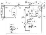
- the passage switching mechanism is provided by the TWV 32.
- the passage switching mechanism may be provided by a plurality of valves.
- the passage switching mechanism has an on-off valve 33, an on-off valve 35, and a TWV.
- the on-off valve 35 is opened and closed by an electromagnetic actuator 53 f.
- the TWV 36 can be driven in a plurality of modes by an electromagnetic actuator 53g.
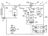
- the auxiliary system 20 has an auxiliary passage 20 a passing through the auxiliary heat source 21.
- the auxiliary passage 20 a is a passage that exits the engine 2, passes through the TWV 36, passes through the auxiliary heat source 21, passes through the EGRC 22, passes through the electric pump 34, and returns to the engine 2.
- the auxiliary system 20 has an auxiliary bypass passage 20 b that bypasses the auxiliary heat source 21.
- the auxiliary bypass passage 20 b branches from the auxiliary passage 20 a upstream of the auxiliary heat source 21 and joins the auxiliary passage 20 a downstream of the auxiliary heat source 21.
- the auxiliary bypass passage 20 b branches from between the TWV 36 and the auxiliary heat source 21.
- the auxiliary bypass passage 20 b joins between the auxiliary heat source 21 and the EGRC 22.
- An opening / closing valve 33 is provided in the auxiliary passage 20a.
- the auxiliary system 20 has a first equipment passage 20 c passing through the EGRC 22.
- An electric pump 34 is provided in the first device passage 20c that forms the warm-up circulation passage WR.
- the auxiliary system 20 has an engine bypass passage 20 d which passes through the auxiliary heat source 21 and the EGRC 22 and does not pass through the engine 2.
- the engine bypass passage 20 d is disposed so as to branch from the downstream side of the EGRC 22 and merge with the upstream side of the auxiliary heat source 21.
- An on-off valve 35 is disposed in the engine bypass passage 20d.
- the engine bypass passage 20d is branched from the first device passage 20c which does not include the second device passage 20e.
- the engine bypass passage 20 d joins between the TWV 36 and the auxiliary heat source 21.
- the auxiliary system 20 has a second equipment passage 20e.
- the second device passage 20 e branches from the auxiliary passage 20 a at the TWV 36.
- the second device passage 20 e bypasses the auxiliary heat source 21 and the EGRC 22.
- the second device passage 20e joins the auxiliary passage 20a outside the warm-up circulation passage WR.
- the TWV 36 supplies the coolant to both the auxiliary passage 20a and the second equipment passage 20e in mode D.
- the TWV 36 supplies the coolant to one of the auxiliary passage 20 a and the second device passage 20 e by switching between mode A and mode C.
- the on-off valve 33 is controlled to be in a closed state when the coolant is passed through the auxiliary heat source 21.
- the on-off valve 33 is controlled to an open state when the auxiliary heat source 21 does not pass the coolant.
- the electric pump 34 is driven when the coolant flows in the warm-up circulation passage WR.
- the on-off valve 35 is controlled to be in the open state when the cooling fluid flows in the warm-up circulation passage WR.
- the on-off valve 35 is controlled to be in the closed state when the coolant does not flow in the warm-up circulation passage WR.
- the auxiliary system 20 provides an equipment warm-up mode, a normal mode, and a heat storage mode.
- the device warm-up mode is provided by controlling the on-off valve 33 in the closed state, driving the electric pump 34, and controlling the on-off valve 35 in the open state.
- the equipment warm-up mode the TWV 36 is controlled to mode A.
- the coolant discharged from the auxiliary heat source 21 circulates through the warm-up circulation passage WR through the EGRC 22 without flowing through the engine 2.
- the coolant discharged from the engine 2 is supplied to the second device passage 20e.
- the TWV 36 is controlled to mode D.
- the on-off valve 33 is controlled to be open, and the on-off valve 35 is controlled to be closed.
- the coolant discharged from the engine 2 is supplied to both the EGRC 22 and the HTC 25.
- the electric pump 34 is controlled to the operating state. The electric pump 34 may not be operated.
- the heat storage mode is provided when the engine 2 is in operation and after the engine 2 is stopped.
- the TWV 36 is controlled to mode D.
- the on-off valve 33 is controlled to be closed, and the on-off valve 35 is controlled to be closed.
- the auxiliary heat source 21 stores heat by the high temperature coolant supplied from the engine 2.
- the auxiliary system 20 executes the heat storage mode.
- the TWV 36 is controlled to mode B.
- the on-off valve 33 is controlled to be closed, and the on-off valve 35 is controlled to be closed.
- the coolant of the engine 2 is exclusively supplied to the auxiliary heat source 21 and heat storage is performed.
- the auxiliary system 20 of this embodiment can be used as an alternative to the other embodiments. Also in this embodiment, the same effect as that of the preceding embodiment can be obtained.
- the heat supplied from the auxiliary heat source 21 is transmitted to the EGRC 22 which is one of the devices 3 without being taken by the engine 2.
- the coolant warmed by the engine 2 can be provided to the HTC 25 which is another device 3 while warming up the EGRC 22 which is one of the devices 3 by circulating the coolant in the warm-up circulation passage WR.
- the TWV 36 separates the warm-up circulation passage WR from the second device passage 20e. This enhances the independence of the two coolant systems.
- the auxiliary bypass passage 20b and the on-off valve 33 may be arranged.
- Warm-up circulation passage WR can be provided by a simple configuration. This is effective when the pressure loss when passing the coolant through the auxiliary heat source 21 is low, or when the heat capacity of the auxiliary heat source 21 is small.
- the auxiliary system 20 of this embodiment can be used as an alternative to the other embodiments. Also in this embodiment, the same effect as that of the preceding embodiment can be obtained.
- Twelfth Embodiment This embodiment is a modification based on the preceding embodiment.
- the passage switching mechanism is provided by the on-off valve 33.
- the passage switching mechanism may be provided by the TWV 32.
- the TWV 32 is disposed at a branch portion between the auxiliary passage 20a and the auxiliary bypass passage 20b.
- the functions of the TWV 32 are as described above. Also in this embodiment, the same effect as that of the preceding embodiment can be obtained.
- This embodiment is a modification based on the preceding embodiment.
- the on-off valve 35 is disposed to open and close the warm-up circulation passage WR.
- the TWV 37 may be employed to open and close the warm-up circulation passage WR.
- the TWV 37 is disposed at a branch portion between the first device passage 20c and the engine bypass passage 20d.
- the TWV 37 is controlled by an electromagnetic actuator 53h.
- the TWV 37 circulates the coolant through the warm-up circulation passage WR by connecting the first device passage 20c and the engine bypass passage 20d.
- the TWV 37 blocks the coolant flowing from the first equipment passage 20c to the engine 2 through the auxiliary passage 20a.
- the independence between the warm-up circulation passage WR and the second device passage 20e is enhanced. Also in this embodiment, the same effect as that of the preceding embodiment can be obtained.
- This embodiment is a modification based on the preceding embodiment.
- electromagnetic actuators 53f and 53i are used to open and close the warm-up circulation passage WR.
- a check valve 38 provided by a mechanically movable element may be employed to open and close the warm-up circulation passage WR.
- a check valve 38 is disposed in the engine bypass passage 20d. The check valve 38 closes so that the coolant does not flow from the TWV 36 to the engine bypass passage 20 d.
- the check valve 38 opens in response to the pressure generated by the electric pump 34 when the electric pump 34 operates. Also in this embodiment, the same effect as that of the preceding embodiment can be obtained.
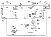
- This embodiment is a modification based on the preceding embodiment.
- the EGRC 22, which is one of the devices 3 is disposed in the first device passage 20c.
- a plurality of devices 3 may be arranged in the second device passage 20c.
- the device (DV1) 22a and the device (DV2) 22b can be arranged in series in the first device passage 20c.
- the HTC 25, the EGRV 27, and the THRB 28 can be disposed as the device 3 disposed in the first device passage 20 c and warmed up by the auxiliary heat source 21.
- a plurality of EGRCs 22 may be arranged. These devices are devices that it is desirable to warm up. For example, since the EHR 26 is a device exclusively for recovering exhaust heat, it may not be necessary to warm up.
- the plurality of devices 22a, 22b in this embodiment can be used as alternatives to the other embodiments. Also in this embodiment, the same effect as that of the preceding embodiment can be obtained.
- This embodiment is a modification based on the preceding embodiment.
- the plurality of devices 22a, 22b are arranged in series.
- the plurality of devices 22a, 22b may be arranged in parallel as illustrated in FIG.
- the plurality of devices 22a, 22b in this embodiment can be used as alternatives to the other embodiments. Also in this embodiment, the same effect as that of the preceding embodiment can be obtained.
- This embodiment is a modification based on the preceding embodiment.
- the auxiliary heat source 21, the EGRC 22, and the electric pump 34 are arranged in this order.
- these sequences may be changed in the warm-up circulation passage WR.
- the electric pump 34 can be disposed in the first device passage 20 c on the upstream side of the EGRC 22.
- the auxiliary heat source 21, the electric pump 34, and the EGRC 22 are arranged in this order.
- the order of elements in the warm-up circulation passage WR in this embodiment can be used as an alternative to the other embodiments. Also in this embodiment, the same effect as that of the preceding embodiment can be obtained.
- This embodiment is a modification based on the preceding embodiment. As illustrated in FIG. 28, the EGRC 22, the auxiliary heat source 21, and the electric pump 34 are arranged in this order.
- the order of elements in the warm-up circulation passage WR in this embodiment can be used as an alternative to the other embodiments. Also in this embodiment, the same effect as that of the preceding embodiment can be obtained.
- This embodiment is a modification based on the preceding embodiment. As illustrated in FIG. 29, the EGRC 22, the electric pump 34, and the auxiliary heat source 21 are arranged in this order.
- the order of elements in the warm-up circulation passage WR in this embodiment can be used as an alternative to the other embodiments. Also in this embodiment, the same effect as that of the preceding embodiment can be obtained.
- Twentieth Embodiment is a modification based on the preceding embodiment. As illustrated in FIG. 30, the electric pump 34, the auxiliary heat source 21, and the EGRC 22 are arranged in this order. The order of elements in the warm-up circulation passage WR in this embodiment can be used as an alternative to the other embodiments. Also in this embodiment, the same effect as that of the preceding embodiment can be obtained.
- This embodiment is a modification based on the preceding embodiment. As illustrated in FIG. 31, the electric pump 34, the EGRC 22, and the auxiliary heat source 21 are arranged in this order.
- the order of elements in the warm-up circulation passage WR in this embodiment can be used as an alternative to the other embodiments. Also in this embodiment, the same effect as that of the preceding embodiment can be obtained.
- the second device passage 20 e is provided to arrange the HTC 25 different from the EGRC 22.
- a plurality of devices may be arranged in the second device passage 20e.
- the HTC 25, EHR 26, EGRV 27 and THRB 28 can be arranged in the second device passage 20e.
- the HTC 25 and the EHR 26 are arranged in series in the second equipment passage 20 e.
- the EGR V 27 and the THRB 28 are arranged in series in the second device passage 20 e.
- the series circuit of HTC 25 and EHR 26 and the series circuit of EGRV 27 and THRB 28 are parallel to each other.
- Twenty-Third Embodiment This embodiment is a modification based on the preceding embodiment. As illustrated in FIG. 33, the plurality of devices 3 HTC 25, EHR 26, EGRV 27 and THRB 28 may be arranged in series with one another. Also in this embodiment, the same effect as that of the preceding embodiment can be obtained.
- the auxiliary system 20 does not include the second equipment passage 20e.
- the auxiliary system 20 has an on-off valve 39 on an auxiliary passage 20 a extending from the engine 2.
- the on-off valve 39 is positioned outside the warm-up circulation passage WR.
- the on-off valve 39 is controlled by an electromagnetic actuator 53i.
- the HTC 25, EHR 26, EGRV 27 and THRB 28 are disposed above the auxiliary passage 20a.
- HTC25, EHR26, EGRV27, and THRB28 are arrange
- the HTC 25 and the EHR 26 are arranged in series in the auxiliary passage 20a.
- the EGRV 27 and the THRB 28 are arranged in series in the auxiliary passage 20a.
- the series circuit of HTC 25 and EHR 26 and the series circuit of EGRV 27 and THRB 28 are parallel to each other.
- Twenty-fifth Embodiment This embodiment is a modification based on the preceding embodiment. As illustrated in FIG. 35, the plurality of devices 3 HTC 25, EHR 26, EGRV 27 and THRB 28 may be arranged in series with one another. Also in this embodiment, the same effect as that of the preceding embodiment can be obtained.
- Twenty-sixth Embodiment This embodiment is a modification based on the preceding embodiment.
- the plurality of devices 3 are disposed outside the warm-up circulation passage WR.
- a plurality of devices 3 may be arranged in the warm-up circulation passage WR.
- the HTC 25, the EHR 26, the EGRV 27, and the THRB 28 are disposed between the EGRC 22 and the electric pump 34.
- the plurality of devices 3 are arranged in series with the warm-up circulation passage WR.
- the plurality of devices 3 are partially arranged in parallel.
- Twenty-seventh Embodiment This embodiment is a modification based on the preceding embodiment. As illustrated in FIG. 37, the plurality of devices 3 HTC 25, EHR 26, EGRV 27 and THRB 28 may be arranged in series with one another. Also in this embodiment, the same effect as that of the preceding embodiment can be obtained.
- This embodiment is a modification based on the preceding embodiment. As illustrated in FIG. 38, an EGRC 422 may be employed. Also in this embodiment, the same effect as that of the preceding embodiment can be obtained.
- auxiliary bypass passage 20b is used as an engine bypass passage 20d.
- second device passage 20e may be used as the engine bypass passage 20d.
- the auxiliary system 20 has an auxiliary passage 20 a passing through the engine 2 and the auxiliary heat source 21.
- the auxiliary system 20 has an auxiliary bypass passage 20 b that bypasses the auxiliary heat source 21.
- a first device passage 20c is provided on the auxiliary passage 20a.
- An EGRC 22 is disposed in the first device passage 20c.
- the auxiliary system 20 has a second equipment passage 20g parallel to both the auxiliary heat source 21 and the EGRC 22.
- the TWV 36 provides the illustrated mode B.
- the second device passage 20g forms a warm-up circulation passage WR which does not include the engine 2 but includes the auxiliary heat source 21 and the EGRC 22. That is, the second device passage 20g functions as an engine bypass passage 20d.
- the EGRC 22 is disposed in the first device passage 20c.
- the HTC 25 is a device whose temperature is controlled by the coolant supplied from the auxiliary passage 20 a.
- the auxiliary system 20 further includes a second device passage 20g in which the HTC 25 which is an additional device other than the EGRC 22 is disposed.
- the warm-up circulation passage WR is formed to share the passage with the second device passage 20g.
- the use of the second device passage 20g as the engine bypass passage 20d in this embodiment can be used as an alternative configuration to the other embodiments. Also in this embodiment, the same effect as that of the preceding embodiment can be obtained.
- the HTC 25 which is one of the devices 3 provided in the second device passage 20g can also be warmed up. By warming up the HTC 25, heating can be accelerated.
- the disclosure in this specification is not limited to the illustrated embodiments.
- the disclosure includes the illustrated embodiments and variations based on them by those skilled in the art.
- the disclosure is not limited to the combination of parts and / or elements shown in the embodiments.
- the disclosure can be implemented in various combinations.
- the disclosure can have additional parts that can be added to the embodiments.
- the disclosure includes those in which parts and / or elements of the embodiments have been omitted.
- the disclosure includes replacements or combinations of parts and / or elements between one embodiment and another embodiment.
- the disclosed technical scope is not limited to the description of the embodiments. It is to be understood that the technical scopes disclosed herein are indicated by the description of the scope of the claims, and further include all modifications within the meaning and scope equivalent to the descriptions of the scope of the claims.
- the terms such as closing, blocking and the like should be interpreted as meaning complete closing or meaning including a predetermined amount of leakage that the system 1 allows.
- the terms opening, communicating, etc. are to be interpreted as meaning a state in which the passage is fully open, or allowing maximum flow, or a state in which a regulated flow is allowed.
- the TWV or the on-off valve may be called a flow control valve, a variable valve, a linear valve or the like.
- FIG. 3 provides a heat storage mode.
- the engine 2 may be warmed up by the heat supplied from the auxiliary heat source 21.
- the passage shown in FIG. 3 may be provided in an engine warm-up mode for warming up the engine 2.
- a three-way valve is provided at the branch portion of the passage, but a three-way valve may be provided at the junction portion of the passage. Also, the function of the three-way valve may be provided by two on-off valves. Thus, the passage switching mechanism can be provided by various valve mechanisms.
- the auxiliary heat source 21 is provided by a heat accumulator.
- the auxiliary heat source 21 may be provided by various heat sources such as a combustion-type coolant heater or an electric-type coolant heater.
- the EGRC 22 is illustrated as one of the devices 3 to be warmed up.
- one or more of the HTC 25, the EGRV 27 and the THRB 28 may be disposed in the equipment passage 20c.
Landscapes
- Engineering & Computer Science (AREA)
- Chemical & Material Sciences (AREA)
- Combustion & Propulsion (AREA)
- Mechanical Engineering (AREA)
- General Engineering & Computer Science (AREA)
- Exhaust-Gas Circulating Devices (AREA)
Abstract
エンジンは、冷却液によって温度が調節される。補助システムは、エンジンに代わって冷却液の温度を上昇させることができる補助熱源を有する。補助システムは、補助熱源を通る冷却液のための補助通路を有する。補助システムは、補助通路から供給される冷却液によって温度調節される機器のひとつであるEGRCを有する。補助システムは、補助熱源とEGRCとを通る暖機循環通路WRを形成する。暖機循環通路WRは、エンジンを流れる冷却液の量を少なくとも抑制し、またはゼロにする。機器が効率的に暖められるエンジン温度調節装置を提供する。
Description
この出願は、2017年8月7日に日本に出願された特許出願第2017-152231号を基礎としており、基礎の出願の内容を、全体的に、参照により援用している。
この明細書における開示は、エンジンの温度調節装置に関する。
特許文献1は、排気ガス還流装置を有する内燃機関のためのシステムを開示する。排気ガス還流装置は、エンジン(内燃機関)の冷却液と熱交換するEGRクーラを有する。さらに、特許文献1は、EGRクーラを暖めるために、エンジンとEGRクーラとを流れる冷却液を燃焼式ヒータによって暖めている。EGRクーラは、暖機の対象となる機器のひとつである。
冷却液の温度は、センサによる検出、または特許文献2および特許文献3に開示される演算による推定によって取得することができる。
従来技術として列挙された先行技術文献の記載内容は、この明細書における技術的要素の説明として、参照により援用される。
特許文献1の構成では、燃焼式ヒータによって暖められた冷却液は、エンジン内の通路を流れる。ところが、エンジンの熱的な容量は、暖機対象機器のひとつであるEGRクーラの熱的な容量より大きい。このため、燃焼式ヒータが発生した多くの熱がエンジンに奪われる。
上述の観点において、または言及されていない他の観点において、内燃機関の温度調節装置にはさらなる改良が求められている。
開示されるひとつの目的は、暖機対象機器を効率的に暖めるエンジン温度調節装置を提供することである。
ここに開示されたエンジン温度調節装置は、冷却液によって温度が調節されるエンジン、およびエンジンに代わって冷却液の温度を上昇させることができる補助熱源を通る冷却液のための補助通路と、補助通路から供給される冷却液によって温度調節される機器と、補助通路に形成され、エンジンを通ることなく、補助熱源と機器とを通る暖機循環通路とを備える。
開示されるエンジン温度調節装置によると、補助熱源は、エンジンに代わって冷却液の温度を上昇させることができる。さらに、補助通路に形成された暖機循環通路を備える。暖機循環通路は、エンジンを通ることなく、補助熱源と機器とを通る。冷却液の一部または全部は、暖機循環通路を流れることによって、エンジンを流れることなく、補助熱源と機器とを流れる。補助熱源は、熱をエンジンに奪われることなく、熱を機器に与えることができる。この結果、暖機対象の機器が効率的に暖められる。
この明細書における開示された複数の態様は、それぞれの目的を達成するために、互いに異なる技術的手段を採用する。請求の範囲およびこの項に記載した括弧内の符号は、後述する実施形態の部分との対応関係を例示的に示すものであって、技術的範囲を限定することを意図するものではない。この明細書に開示される目的、特徴、および効果は、後続の詳細な説明、および添付の図面を参照することによってより明確になる。
図面を参照しながら、複数の実施形態を説明する。複数の実施形態において、機能的におよび/または構造的に対応する部分および/または関連付けられる部分には同一の参照符号、または百以上の位が異なる参照符号が付される場合がある。対応する部分および/または関連付けられる部分については、他の実施形態の説明を参照することができる。
第1実施形態
図1において、システム1は、エンジン2(内燃機関)と熱交換する冷却液を扱う装置を提供する。システム1は、エンジン温度調節装置を提供する。冷却液は、水、エチレングリコール、またはそれらの混合液である。システム1は、熱源(HS)としてのエンジン2の廃熱を冷却液によって大気に放出し、エンジン2の温度を調節する。エンジン2は、冷却液によって温度が調節される。システム1は、冷却液と機器3とを熱交換させる。機器3は、冷却液によって冷却または加熱される受動的機器と、冷却液を加熱することができる能動的機器とを有する。システム1は、車両に搭載されている。システム1は、車両、航空機、船舶、地上設置型のエンジン利用機器に適用することができる。
図1において、システム1は、エンジン2(内燃機関)と熱交換する冷却液を扱う装置を提供する。システム1は、エンジン温度調節装置を提供する。冷却液は、水、エチレングリコール、またはそれらの混合液である。システム1は、熱源(HS)としてのエンジン2の廃熱を冷却液によって大気に放出し、エンジン2の温度を調節する。エンジン2は、冷却液によって温度が調節される。システム1は、冷却液と機器3とを熱交換させる。機器3は、冷却液によって冷却または加熱される受動的機器と、冷却液を加熱することができる能動的機器とを有する。システム1は、車両に搭載されている。システム1は、車両、航空機、船舶、地上設置型のエンジン利用機器に適用することができる。
受動的機器は、温度調節されることが望ましい機器3である。受動的機器の典型的な一例は、後述のEGRクーラ(EGRC)22によって提供される。機器3は、エンジン2で加熱された冷却液でも機能を発揮するが、エンジン2が低温であるときには、加熱が望ましい機器である。EGRC22は、高温機器とも呼ばれる。機器3には、後述の複数の例を含む。機器3は、例えば、EGRガスの温度を調節するEGRクーラ(EGRC)、暖房用のヒータコア(HTC)、エンジン2の排気から熱を回収する排気熱回収器(EHR)、EGRガスの量を調節するEGRバルブ(EGRV)、エンジン2の吸気量を調節するスロットルボディ(THRB)などの少なくともひとつを含むことができる。EGRC22は、主要機器と呼ばれる。HTC、EHR、EGRV、THRBは、追加機器と呼ばれる。機器3は、エンジン2の作動を補助する機器でもある。
能動的機器は、エンジン2に代わる熱源としての補助熱源(AHS)である。補助熱源は、エンジン2に代わって冷却液の温度を上昇させることができる。補助熱源は、冷却液の熱を蓄える蓄熱器、または廃熱を生じる機器の少なくともひとつを含む。エンジン2の冷却液は、補助熱源21に蓄熱する。蓄熱は、高温の冷却液そのものを蓄えるか、または、化学的な反応によって蓄熱と放熱とを切替可能な蓄熱材に熱を蓄えることによって提供できる。廃熱を生じる機器は、エンジン2以外の機器である。廃熱を生じる機器は、電子回路(例えば、インバータ回路)を含む機器、バッテリ機器、電気ヒータ機器、排気熱回収機器などの少なくともひとつを含むことができる。
システム1は、エンジン2を冷却する機能と、冷却液により受動的機器の温度を調節する機能と、能動的機器によって受動的機器を暖める機能とを少なくとも提供する。システム1は、能動的機器によってエンジン2を暖める機能を提供してもよい。なお、この明細書において、冷却液の温度に関して、冷たい、冷間、低温等の語句は、一例として、20℃以下を指す。一方、冷却液の温度に関して暖かい、温間、高温等の語句は、60℃以上、望ましくは80℃以上を指す。さらに、暖機の語句は、初期の温度より高い温度への移行過程を指す。暖機の語句は、一例として、冬季の0℃からの温度上昇、典型的には0℃から60℃以上への温度上昇を意味している。
システム1は、エンジン2のための冷却システム10と、機器3の温度調節のための補助システム20とを有する。冷却システム10は、エンジン2の温度を調節する。冷却システム10は、エンジン2を冷却する。冷却システム10は、エンジン2と熱交換する冷却液を循環的に流す。補助システム20は、冷却システム10を補助するシステムである。補助システム20は、エンジン2の温度が低すぎる場合に、エンジン2を暖める暖機処理を提供することによって冷却システム10を補助する。補助システム20は、冷却液を利用する追加的なシステムでもある。補助システム20は、エンジン2を補助する機器3の温度を調節する。機器3の温度の調節は、機器3の温度を冷却液によって下げる冷却と、機器3の温度を冷却液によって上げる加熱との両方を含む。補助システム20は、エンジン2の温度調節と、機器3の温度調節との両方を提供している。
冷却システム10は、冷却液と外気との熱交換を提供するラジエータ12を有する。ラジエータ12は、エンジン2の廃熱を大気に放熱する。エンジン2とラジエータ12とは、冷却液が循環する放熱通路10aを形成する。
冷却システム10は、エンジン2に内蔵されている内蔵ポンプ13を有する。内蔵ポンプ13は、エンジン2によって駆動される。内蔵ポンプ13は、モータによって駆動されてもよい。内蔵ポンプ13は、放熱通路10aに対して、順方向へ冷却液を送る。内蔵ポンプ13は、エンジン2が燃焼によって作動している間中、冷却液を送り続ける。冷却システム10は、内蔵ポンプ13なしで構成されてもよい。
冷却システム10は、電動ポンプ14を有する。電動ポンプ14は、モータ53cによって駆動される。電動ポンプ14は、放熱通路10aに対して、順方向へ冷却液を送る。電動ポンプ14は、エンジン2とラジエータ12との間に位置している。電動ポンプ14は、後述のサーモスタットバルブ15とエンジン2との間に位置している。電動ポンプ14は、後述の暖機循環通路WRにも属している。内蔵ポンプ13および電動ポンプ14は、冷却システム10に既設のポンプによって提供できる。
冷却システム10は、サーモスタットバルブ15を有する。サーモスタットバルブ15は、冷却液の温度に応答してラジエータ12を流れる冷却液の量を調節する。サーモスタットバルブ15は、電気的に制御可能な電磁弁またはサーモスタットによって開閉される弁によって提供される。サーモスタットバルブ15は、冷却液の温度に応答して放熱通路10aを開閉可能である。サーモスタットバルブ15は、冷却液の温度が所定温度より低いとき、ラジエータ12を流れる冷却液を遮断可能である。サーモスタットバルブ15は、冷却液の温度を、下限温度を上回り、かつ上限温度を下回るように調節する。サーモスタットバルブ15は、エンジン2の温度が下限温度を下回るとき、ラジエータ12の流量を減少状態、または遮断状態として、エンジン2の暖機を図る。
冷却システム10は、冷却液がエンジン2とラジエータ12との両方を流れる放熱通路10aを有する。放熱通路10aは、エンジン2の中を通り、エンジン2から出て、ラジエータ12を通り、再びエンジン2に戻る。放熱通路10aは、エンジン2、ラジエータ12、サーモスタットバルブ15、電動ポンプ14、内蔵ポンプ13、エンジン2の順で冷却液を流す。
補助システム20は、補助熱源21を有する。補助熱源21は、システム1の全部または一部が低温であるときに、冷却液を暖める。暖かい冷却液は、エンジン2、および/または機器3を暖める。エンジン2、および/または機器3を暖める機能は、暖機と呼ばれる。補助熱源21は、蓄熱器とも呼ばれる。蓄熱器は、エンジン2が80℃以上の通常温度に到達した後、すなわち通常運転状態における高温の冷却液を蓄える。蓄熱器は、システム1の全部または一部が低温であるときに、高温の冷却液をシステム1に供給する。蓄熱器は、冷却液を暖めることにより、エンジン2、および/または機器3を暖機する。
補助システム20は、EGRC22(EGRクーラ)を有する。EGRC22は、排気系統から吸気系統へ戻されるEGRガスの温度を調節する。EGRC22は、エンジン2の通常運転状態では、EGRガスを冷却する。EGRC22は、EGRC22自身の温度が、EGRガスに結露を生じるほどに低温であるときには、暖められること、すなわち暖機されることが望ましい。
補助システム20は、エンジン2と補助システム20との間の通路の流体的な連通状態を制御する冷却液制御弁(以下、CCVと呼ぶ)31を有する。CCV31は、開閉弁または流量調節弁によって提供される。CCV31は、エンジン2と補助システム20との間に設けられている。CCV31は、エンジン2からの冷却液の出口に配置されている。CCV31は、CCV31を駆動するための電磁的なアクチュエータ53aを有する。CCV31は、少なくとも通路を開閉する。CCV31は、閉弁状態においても、わずかに流体の連通を許容してもよい。CCV31は、完全に閉じられない場合がある。
サーモスタットバルブ15が放熱通路10aを閉じ、かつ、CCV31が閉弁状態に制御されることで、エンジン2内を流れる冷却液の循環を止めることができる。このような液止制御モードは、エンジン2を暖機する場合に提供される。液止制御モードは、エンジン2の速い暖機に貢献する。
補助システム20は、補助熱源21を制御するための通路切換機構を有する。通路切換機構は、少なくとも補助熱源21によって冷却液を加熱するか否かを切り換える。さらに、通路切換機構は、補助熱源21の熱を冷却液を介してEGRC22に伝達するかを切り換える。通路切換機構は、補助熱源21とEGRC22とをエンジン2を含まない閉回路に置くか、エンジン2を含む閉回路に置くかを切り換える。通路切換機構は、ひとつまたは複数の制御弁と、通路とによって提供することができる。通路切換機構は、弁機構とも呼ばれる。通路切換機構は、冷却液のための通路の分岐部分または合流部分に設けられて流路を切り換える三方弁(以下、TWVという)32によって提供可能である。TWV32は、補助熱源21を通して冷却液を流す状態と、補助熱源21に冷却液を流さない状態とを含む少なくとも2つのモードを提供する。TWV32の連通状態は、電磁的なアクチュエータ53bによって切換可能である。
補助システム20は、冷却液がエンジン2と補助熱源21との両方を流れる冷却液のための補助通路20aを有する。冷却システム10と補助システム20とは、エンジン2に対して並列に配置されている。それらの分岐部分は、図1に図示されるようなT字管またはエンジン2内のギャラリによって提供することができる。それらの合流部分も同様である。
補助通路20aは、補助熱源21に熱を蓄える蓄熱モード、および補助熱源21の熱を放出する放熱モードとを提供する。補助通路20aは、エンジン2から、CCV31を通り、TWV32を通り、補助熱源21を通り、さらにEGRC22を通り、電動ポンプ14を通り、エンジン2に戻る閉回路を提供する。補助通路20aは、エンジン2と補助熱源21とを含む環状の通路である。補助通路20aは、複数の管路を含む。
補助システム20は、補助バイパス通路20bを有する。補助バイパス通路20bは、冷却液が補助熱源21を流れることなく、補助熱源21の上流側から下流側へと流れることを許容する。補助バイパス通路20bは、補助熱源21による加熱の一部または全部を無効化する無効化通路とも呼ばれる。補助バイパス通路20bは、TWV32から分岐し、補助熱源21とEGRC22との間において補助通路20aに合流している。言い換えると、TWV32は、補助通路20aから補助バイパス通路20bが分岐する分岐部分に設けられている。
補助システム20は、冷却液がEGRC22を流れる機器通路20cを有する。機器通路20cには、EGRC22が配置されている。機器通路20cは、EGRC22において利用される冷却液をEGRC22に供給する。機器通路20cは、補助通路20aの一部である。機器通路20cは、補助熱源21より下流に設けられている。機器通路20cは、補助通路20aと補助バイパス通路20bとの合流部よりも下流に位置している。EGRC22は、補助通路20aから供給される冷却液によって温度調節される機器3のひとつである。
補助システム20は、エンジンバイパス通路20dを有する。エンジンバイパス通路20dは、冷却液の全部がエンジン2を流れることなくEGRC22を流れるか、または冷却液の一部がエンジン2を通り冷却液の残部がEGRC22を流れることを許容する。エンジンバイパス通路20dは、エンジン2を全く通らない冷却液の循環的な流れを許容する。なお、上記冷却液の一部は、制限された量である。上記冷却液の一部は、上記冷却液の残部より少ない場合がある。
エンジンバイパス通路20dは、電動ポンプ14とエンジン2との間から分岐し、CCV31の下流において補助通路20aに合流している。エンジンバイパス通路20dは、補助システム20の中において、エンジン2をバイパスする経路を提供している。言い換えると、エンジンバイパス通路20dは、補助熱源21から見て、エンジン2をバイパスする経路を提供している。
エンジンバイパス通路20dは、エンジン2を通ることなく、補助熱源21とEGRC22との両方を通る閉回路を形成可能である。この閉回路は、暖機循環通路WRとも呼ばれる。暖機循環通路WRは、補助通路20aに形成されている。暖機循環通路WRは、補助熱源21と、機器のひとつであるEGRC22とを通る冷却液のための閉回路を提供する。暖機循環通路WRは、エンジン2を通ることがない冷却液のための閉回路を提供する。冷却液の一部または全部は、暖機循環通路を流れることができる。冷却液の一部または全部は、エンジン2の内部通路を流れることなく、補助熱源21とEGRC22とを流れる。
暖機循環通路WRは、補助熱源21によって温度が上昇した冷却液の一部または全部を、エンジン2に供給することなく、EGRC22に供給する。この結果、補助熱源21を流れる冷却液の量よりも、エンジン2を流れる冷却液の量が少なく抑制される。少なく抑制の態様には、エンジン2を流れる冷却液の量をゼロ(0)にする場合が含まれている。暖機循環通路WRは、補助熱源21とEGRC22とを含み、エンジン2を含まない冷却液の循環的な流れを許容する。暖機循環通路WRは、補助熱源21とEGRC22とを含むが、エンジン2を含まない閉回路を提供することによって、補助熱源21を流れる冷却液の量よりも、エンジン2を流れる冷却液の量を少なくとも抑制する。望ましい形態では、暖機循環通路WRは、エンジン2を通ることなく、補助熱源21とEGRC22とを通る通路を提供する。この通路が提供されることで、補助熱源21によって温度が上昇した冷却液の一部または全部を、エンジン2に供給することなく、機器3(EGRC22)に供給することが可能となる。
暖機循環通路WRは、補助熱源21によって温度が上昇した冷却液の一部または全部を、エンジン2に供給することなく、EGRC22に供給する。CCV31は、完全に閉じられる場合がある。この場合、暖機循環通路WRは、補助熱源21によって温度が上昇した冷却液を、エンジン2に供給することなく、EGRC22に供給する。この場合、エンジン2の低温に起因する悪影響が回避される。CCV31は、完全に閉じられない場合がある。この場合、暖機循環通路WRは、補助熱源21によって温度が上昇した冷却液の一部を、エンジン2に供給し、上記冷却液の残部をEGRC22に供給する。この場合、エンジン2の低温に起因する悪影響が抑制される。
電動ポンプ14は、冷却システム10と補助システム20とに共通の通路に設けられている。電動ポンプ14は、補助通路20aが放熱通路10aに合流する合流部より下流に位置している。電動ポンプ14は、放熱通路10aからエンジンバイパス通路20bが分岐する分岐部分より上流に位置している。言い換えると、電動ポンプ14の上流側に補助通路20aが合流し、電動ポンプ14の下流側からエンジンバイパス通路20dが延び出している。
システム1は、制御装置(ECU)51を有する。制御装置51は、電子制御装置(Electronic Control Unit)である。制御装置は、少なくともひとつの演算処理装置(CPU)と、プログラムとデータとを記憶する記憶媒体としての少なくともひとつのメモリ装置(MMR)とを有する。制御装置51は、コンピュータによって読み取り可能な記憶媒体を備えるマイクロコンピュータによって提供される。記憶媒体は、コンピュータによって読み取り可能なプログラムを非一時的に格納する非遷移的実体的記憶媒体である。記憶媒体は、半導体メモリまたは磁気ディスクなどによって提供されうる。制御装置51は、ひとつのコンピュータ、またはデータ通信装置によってリンクされた一組のコンピュータ資源によって提供されうる。プログラムは、制御装置51によって実行されることによって、制御装置51をこの明細書に記載される装置として機能させ、この明細書に記載される方法を実行するように制御装置51を機能させる。
制御システムは、制御装置51に入力される情報を示す信号を供給する複数の信号源を入力装置として有する。制御システムは、制御装置51が情報をメモリ装置に格納することにより、情報を取得する。制御システムは、制御装置51によって挙動が制御される複数の制御対象物を出力装置として有する。制御システムは、メモリ装置に格納された情報を信号に変換して制御対象物に供給することにより制御対象物の挙動を制御する。
制御システムに含まれる制御装置51と信号源と制御対象物とは、多様な要素を提供する。それらの要素の少なくとも一部は、機能を実行するためのブロックと呼ぶことができる。別の観点では、それらの要素の少なくとも一部は、構成として解釈されるモジュール、またはセクションと呼ぶことができる。さらに、制御システムに含まれる要素は、意図的な場合にのみ、その機能を実現する手段ともよぶことができる。信号源は、複数の温度センサ52a、52b、52cによって提供される。制御対象物は、複数のアクチュエータ53a、53bおよびモータ53cによって提供される。
制御システムが提供する手段および/または機能は、実体的なメモリ装置に記録されたソフトウェアおよびそれを実行するコンピュータ、ソフトウェアのみ、ハードウェアのみ、あるいはそれらの組合せによって提供することができる。例えば、制御装置51がハードウェアである電子回路によって提供される場合、それは多数の論理回路を含むデジタル回路、またはアナログ回路によって提供することができる。
このシステム1によると、以下の機能が提供される。エンジン2の温度を調節するために、基本的な冷却システム10が提供される。EGRクーラのようなEGRC22の温度を調節するために、エンジン2の冷却液を利用する補助システム20が提供される。EGRC22の暖機を補助するために、補助熱源21の熱をEGRC22に供給する補助システム20が提供される。EGRC22を暖機するとき、補助熱源21とEGRC22とを通り、エンジン2を通らない暖機循環通路WRが提供される。暖機循環通路WRは、補助熱源21の熱がエンジン2に奪われる現象を抑制する。エンジン2の暖機は、主としてエンジン2自身の発熱によって実現される。ただし、エンジン2の暖機を補助するために、補助熱源21の熱をエンジン2に供給する補助システム20を提供してもよい。補助熱源21が蓄熱器である場合には、エンジン2の冷却液を利用して、次の暖機のための熱を蓄熱できる補助システム20が提供される。
図2は、通常モードにおける冷却液の流れを示す。破線は、漏れ流量以上の冷却液が流れない通路を示す。エンジン2の暖機が完了し、エンジン2の温度が冷却システム10によって所定の温度に調節されており、しかも補助熱源21が十分に蓄熱している場合、通常モードが実行される。通常モードにおいて、電動ポンプ14は運転状態にあり、CCV31は開弁状態にあり、TWV32は、補助バイパス通路20bに冷却液を供給する。同時に、機器通路20cに流れる冷却液は、EGRC22の温度を調節する。ここでは、EGRクーラによってEGRガスの温度が調節される。
図3は、蓄熱モードにおける冷却液の流れを示す。エンジン2の暖機が完了し、エンジン2の温度が冷却システム10によって所定の温度に調節されており、しかも補助熱源21に蓄熱する場合、蓄熱モードが実行される。蓄熱モードにおいて、電動ポンプ14は運転状態にあり、CCV31は開弁状態にあり、TWV32は、補助熱源21に冷却液を供給する。エンジン2の冷却液は、補助熱源21に蓄熱する。同時に、機器通路20cに流れる冷却液は、EGRC22の温度を調節する。蓄熱モードにおいて、EGRC22の暖機が同時的に進行する。しかも、EGRC22の暖機は、エンジン2から供給される熱と、補助熱源21から供給される熱とによって実行される。
図4は、機器暖機モードにおける冷却液の流れを示す。EGRC22のみを暖機する場合に、機器暖機モードが提供される。機器暖機モードにおいて、電動ポンプ14は運転状態にあり、CCV31は閉弁状態にあり、TWV32は、補助熱源21に冷却液を供給する。CCV31が閉弁しているため、冷却液は、電動ポンプ14からエンジンバイパス通路20dを通り、CCV31の下流に到達する。すなわち、冷却液は、補助システム20の中だけを循環する。冷却液は、TWV32、補助熱源21,EGRC22、電動ポンプ14、およびエンジンバイパス通路20dを流れる。冷却液は、暖機循環通路WRを循環する。機器暖機モードでは、冷却液がエンジン2を通らない。このため、補助熱源21の熱をエンジン2に奪われることなく、EGRC22に供給することができる。EGRC22がEGRクーラである場合には、EGRクーラの温度を早く暖めることができる。この結果、低温のEGRクーラに起因する結露を抑制できる。また、エンジン2が始動される初期からEGRガスを供給することができる。
図5は、エンジン暖機モードにおける冷却液の流れを示す。EGRC22の暖機を要しない場合に、このモードが提供される。このモードでは、電動ポンプ14は運転状態にあり、CCV31は閉弁状態にあり、TWV32は、補助バイパス通路20bに冷却液を供給する。この場合、エンジン2の温度を冷却システム10によって暖機、または調節し、かつ、冷却液によってEGRC22の温度を調節しながら、補助熱源21に冷却液を通さない状態を実現できる。このモードは、例えば、EGRC22の暖機を要しない中間温度帯において利用できる。
図6は、温度センサ52a、52b、52cによる検出値と、制御装置51における複数の判定処理の閾値を示す。これら閾値は、例えば例1(Ex.1)または例2(Ex.2)のような値をもつことができる。単位は、摂氏温度である。検出値および閾値の記号は、後述のフローチャートにおいて使用されている。
エンジン暖機完了温度T1は、EGRクーラ暖機完了温度T2eより高い(T1>T2e)。これにより、通常の運転では、先にEGRC22の暖機が完了し、遅れてエンジン2の暖機が完了する。ただし、特殊な運転では、逆になることがある。EGRクーラ暖機開始温度T2sは、EGRクーラ暖機完了温度T2eより低い(T2s<T2e)。EGRクーラ暖機開始温度T2sは、極低温の条件を設定している。これにより、極低温の場合、エンジン2の暖機は実行されるが、EGRC22の暖機は実行されない。蓄熱量有無判定温度T3は、補助熱源21が提供する熱が、EGRC22を暖気するために十分であるか否かを判定するための閾値を提供する。放熱完了温度T4は、補助熱源21からの熱を利用可能な下限を設定している。この実施形態では、放熱完了温度T4は、EGRクーラ暖機完了温度T2eに等しい。蓄熱開始温度T5は、エンジン2が冷却液を十分に温めた状態を示している。蓄熱開始温度T5は、蓄熱した状態を長期間にわたって維持できる温度でもある。
図7は、TWV32は、3ポート多位置弁とも呼ばれる。この実施形態では、モードAとモードBとが利用される。TWV32は、モードAにおいて、ポートPaとポートPcとを連通する。モードAでは、冷却液は、補助熱源21に流れることなく、補助バイパス通路20bに流れる。TWV32は、モードBにおいて、ポートPaとポートPbとを連通する。モードBでは、冷却液は、補助熱源21に流れ、補助バイパス通路20bに流れない。TWV32は、モードCにおいて、ポートPbとポートPcとを連通する。TWV32は、モードDにおいて、ポートPaとポートPbとポートPcとのすべてを連通する。これらモードC、モードDは、後述の実施形態で利用される。
図8、図9、図10、および図11は、補助システム20に関する制御を示す。制御は、制御装置51によって実行される。制御は、エンジン2が始動される前のシステム1の電源投入から開始される。
図8において、ステップ161では、温度センサ52a、52bが検出するエンジン出口冷却液温度Ta(以下、温度Taという)と、蓄熱器出口冷却液温度Tb(以下、温度Tbという)とが取得される。ステップ162では、温度Ta<閾値T1か否かが判定される。閾値T1は、エンジン暖機完了温度である。温度Taが閾値T1より低い場合、エンジン2の暖機が必要である。温度Taが閾値T1より低くない場合、エンジン2の暖機が必要ではない。よって、ステップ162は、エンジン2の暖機の要否を判定する判定部を提供している。
ステップ163では、CCV31が閉弁状態に制御される。これにより、エンジン2の冷却水の利用が停止され、エンジン2は冷却システム10によって暖機される。
ステップ164は、温度Ta<閾値T2eか否かが判定される。閾値T2eはEGRクーラ暖機完了温度である。温度Taが閾値T2eより低い場合、EGRC22の暖機が必要である。温度Taが閾値T2eより低くない場合、EGRC22の暖機が必要ではない。ここでは、温度TaによってEGRC22の暖機の要否が判定される。ステップ164は、EGRC22の暖機の要否を判定する判定部を提供している。
ステップ165は、温度Ta≧閾値T2sか否かが判定される。閾値T2sはEGRクーラ暖機開始温度である。温度Taが閾値T2sより低い場合、EGRC22の温度が低すぎる。温度Taが閾値T2s以上の場合、EGRC22は暖機可能な温度である。ステップ165は、EGRC22が暖機可能か否かを判定する判定部を提供している。
ステップ166は、温度Tb≧T3か否かが判定される。閾値T3は、蓄熱量有無判定温度である。温度Tbが閾値T3より低い場合、補助熱源21から供給できる熱が十分ではない。温度Tbが閾値T3以上の場合、補助熱源21は十分な熱を供給できる。ステップ166は、補助熱源21がEGRC22の暖機のための熱量を供給できるか否かを判定する判定部を提供している。
ステップ164またはステップ166において否定的に判定された場合、処理は、ステップ167へ分岐する。ステップ167では、TWV32がモードAに制御される。このとき、システム1は、図5に示すエンジン暖機モードである。この場合、補助熱源21は利用されない。ステップ168では、エンジン2が始動される。同時に、内蔵ポンプ13および電動ポンプ14が始動される。
ステップ169では、エンジン内冷却液温度Tc(以下、温度Tcという)が取得される。このとき、CCV31は閉弁状態であるので、エンジン2の内部における冷却液の温度は、エンジン2の内部の温度センサまたは推測演算処理によって求められる。温度Tcが推定される場合、特許文献1または特許文献2の内容を参照により援用することができる。ステップ170では、温度Tc<T1か否かが判定される。温度Tcが閾値T1より低い場合、エンジン2の暖機がさらに必要である。温度Tcが閾値T1より低くない場合、エンジン2の暖機が必要ではない。よって、ステップ170は、エンジン2の暖機の要否を判定する判定部を提供している。ステップ169とステップ170との処理が繰り返されることにより、エンジン2の暖機が図られる。ステップ171では、CCV31が開弁状態に制御される。これにより、システム1は、図2に示す通常モードへ移行する。
ステップ167-171の処理では、EGRC22の暖機は専ら自らがEGRガスから受ける熱によって実現される。言い換えると、EGRC22を特別に暖機することなく、エンジン2の暖機が図られる。ステップ169-170のループは、エンジン2を暖機するエンジン暖機部Vを提供する。
ステップ164からステップ166のすべてにおいて肯定的に判定された場合、ステップ172に進む。ステップ172では、TWV32がモードBに制御される。このとき、システム1は、図4に示す機器暖機モードである。この場合、補助熱源21が利用される。ステップ173では、エンジン2が始動される。同時に、内蔵ポンプ13および電動ポンプ14が始動される。
エンジン2の始動により、エンジン2の暖機が進行する。同時に、補助熱源21を用いてEGRC22の暖機が進行する。補助熱源21は、EGRC22のすぐ上流側に配置されている。このため、補助熱源21の熱が効率的にEGRC22に伝達される。また、機器暖機モードにおいては、冷却液は、エンジン2を流れることなく、暖機循環通路WRを循環的に流れる。このため、比較的熱容量が大きいエンジン2によって補助熱源21の熱が奪われにくい。このため、補助熱源21の熱をEGRC22の暖機に有効に利用することができる。
ステップ174では、温度Tcが取得される。ステップ175では、温度Tbが取得される。ステップ176では、温度Tc<閾値T1か否かが判定される。ステップ177では、温度Tc<閾値T2eか否かが判定される。ステップ178では、温度Tc≧閾値T4か否かが判定される。閾値T4は、放熱完了温度である。ステップ176-178のすべてにおいて肯定的に判定される場合、ステップ174-178の処理をくりかえす。ここでは、エンジン2の暖機と、補助熱源21によるEGRC22の暖機との両方が進行する。ステップ174-178のループは、補助熱源21を利用する補助暖機部IVを提供する。
やがて、エンジン2の暖機が進行し、ステップ176において否定的に判定されると、ステップ180へ分岐する。ステップ180では、CCV31が開弁状態に制御される。これにより、エンジン2で発生した熱が補助システム20に供給される。言い換えると、システム1は、図3に示す蓄熱モードへ移行する。
ステップ181では、温度Taと温度Tbとが取得される。ステップ182では、温度Ta<T2eか否かが判定される。ここでは、温度TaによってEGRC22の暖機の要否が判定される。ステップ183では、温度Tb≧T4か否かが判定される。ここでは、補助熱源21による熱供給が完了したか否かが判定される。ステップ182-183のすべてにおいて肯定的に判定される場合、ステップ181-183の処理をくりかえす。ここでは、エンジン2および補助熱源21によるEGRC22の暖機が進行する。ステップ181-183のループは、補助熱源21に蓄熱する蓄熱部IIIを提供する。
やがて、温度Taが閾値T2e以上となるか、または補助熱源21が熱の供給を終了すると、ステップ184へ移行する。ステップ184では、TWV32がモードAに制御される。すなわち、補助熱源21によるEGRC22の暖機が終了する。
ステップ177またはステップ178において否定的に判定されると、ステップ179に進む。ステップ177の処理は、温度TcによってEGRC22の暖機が完了したことを間接的に判定する処理である。ステップ178の処理は、補助熱源21の熱が十分でなくなったことを判定する処理である。ステップ179では、TWV32がモードAに制御される。すなわち、補助熱源21によるEGRC22の暖機が終了する。この後、ステップ169へ進み、エンジン暖機モードによるエンジン2の暖機が継続される。
ステップ162に戻り、ステップ162において否定的に判定された場合、ステップ185へ進む。ステップ185では、CCV31が開弁状態に制御される。ステップ186-188は、それぞれステップ164-166と同じ処理を提供する。ステップ186-188のすべてにおいて肯定的に判定された場合、ステップ189に進む。ステップ189では、TWV32がモードBに制御される。このとき、システム1は、図3に示す蓄熱モードである。この場合、補助熱源21が利用される。ステップ190では、エンジン2が始動される。同時に、内蔵ポンプ13および電動ポンプ14が始動される。この結果、エンジン2の暖機も進行する。ステップ190の後、ステップ181へ進む。
ステップ186またはステップ188において否定的に判定されると、ステップ191へ進む。ステップ191では、TWV32がモードAに制御される。このとき、システム1は、図2に示す通常モードである。この場合、補助熱源21は利用されない。ステップ192では、エンジン2が始動される。同時に、内蔵ポンプ13および電動ポンプ14が始動される。ステップ192を通る処理により、補助熱源21を利用しない通常の通常処理部IIが提供される。
ステップ165に戻り、ステップ165において否定的に判定された場合、接続ステップCを経由して、図9のステップ261へ進む。温度Taが、閾値T2eより低く、しかも、閾値T2sより低い場合、EGRC22の暖機が必要であるが、EGRC22の温度が低すぎる場合であると考えられる。ステップ261では、TWV32がモードAに制御される。ステップ262では、エンジン2が始動され、同時に内蔵ポンプ13および電動ポンプ14が始動される。ステップ263では、温度Tcが取得される。ステップ264では、温度Tc<閾値T1か否かが判定される。ステップ265では、温度Tc<閾値T2sか否かが判定される。ステップ264-265のすべてにおいて肯定的に判定される場合、ステップ263-265をくりかえす。この場合、エンジン2の内部温度およびEGRC22の温度が低すぎると判定できる。このとき、システム1は、図5に示すエンジン暖機モードである。
やがて、エンジン2の暖機が進行すると、温度Tcが閾値T2s以上になる。この場合、ステップ265からステップ266へ進む。ステップ266では、TWV32がモードBに制御される。このとき、図4に示す機器暖機モードである。ステップ267-271は、それぞれステップ174-178と同じ処理を提供する。ステップ269-271のすべてにおいて肯定的に判定された場合、ステップ267-271をくりかえす。ここでは、エンジン2の暖機と、補助熱源21によるEGRC22の暖機との両方が進行する。
やがて、エンジン2の暖機が進行し、ステップ269において否定的に判定されると、ステップ272へ分岐する。ステップ272-276は、それぞれステップ180-184と同じ処理を提供する。ステップ273-275の期間中、システム1は、図3に示す蓄熱モードである。
やがて、ステップ276へ移行する。ステップ276では、TWV32がモードAに制御される。すなわち、補助熱源21によるEGRC22の暖機が終了する。
ステップ270またはステップ271において否定的に判定されると、ステップ277へ進む。このとき、システム1は、図5に示すエンジン暖機モードである。ステップ277-280は、それぞれステップ179、169-171と同じ処理を提供する。
ステップ264へ戻り、ステップ264において否定的に判定されると、ステップ281へ進む。ステップ281では、CCV31が開弁状態に制御される。このとき、システム1は、図2に示す通常モードである。ステップ282では、温度Taが取得される。ステップ283では、温度Ta<閾値T2sか否かが判定される。ステップ283において肯定的に判定される場合、ステップ282-283をくりかえす。この場合、エンジン2の出口温度が低すぎると判定できる。
やがて、エンジン2の暖機が進行すると、温度Taが閾値T2s以上になる。この場合、ステップ283からステップ284へ進む。ステップ284では、TWV32がモードBに制御される。これにより、図2に示す通常モードから、図4に示す機器暖機モードに移行する。ステップ284の後、ステップ273へ進む。
ステップ187に戻り、ステップ187において否定的に判定された場合、接続ステップDを経由して、図10のステップ361へ進む。ステップ361では、TWV32がモードAに制御される。ステップ362では、エンジン2が始動され、同時に内蔵ポンプ13および電動ポンプ14が始動される。
ステップ363では、温度Taが取得される。ステップ364では、温度Ta<閾値T2sか否かが判定される。ステップ364において肯定的に判定される場合、ステップ363-264をくりかえす。このとき、システム1は、図2に示す通常モードである。
やがて、温度Taが閾値T2s以上になると、ステップ364からステップ365へ進む。ステップ365では、TWV32がモードBに制御される。これにより、図2に示す通常モードから、図3に示す蓄熱モードに移行する。ステップ365-369は、それぞれステップ284、273-276と同じ処理を提供する。
図11は、図8、図9、および図10に示される暖機モードの後に実行される暖機後モードを示す。ステップ461では、CCV31が開弁状態に制御される。CCV31は、常開型である。ステップ462では、TWV32がモードAに制御される。TWV32は、アクチュエータ53bからの制御がない場合、モードAになる。ステップ463では、温度Taが取得される。ステップ464では、温度Ta<閾値T5か否かが判定される。閾値T5は、蓄熱開始温度である。温度Taが閾値T5より低い場合、ステップ463-464をくりかえす。このとき、システム1は、図2に示す通常モードである。ステップ464において、温度Taが閾値T5以上になると、ステップ465へ分岐する。
ステップ465では、TWV32がモードBに制御される。これにより、システム1は、図3に示す蓄熱モードに移行する。ステップ466では、熱源HSであるエンジン2の状態が取得される。ここでは、エンジン2が継続的に運転されているか否かを示す信号が取得される。例えば、エンジン2の回転数、イグニッションスイッチのオンまたはオフ、車両の走行を示す速度が取得される。ステップ467では、エンジン2が継続的に運転されているか否かが判定される。エンジン2が継続的に運転されている場合、ステップ466-467をくりかえす。これにより、エンジン2からの廃熱が補助熱源21に蓄熱される。また、エンジン2が再始動された場合に、補助熱源21の熱を利用してEGRC22を暖機することができる。やがて、エンジン2の継続運転が停止されると、ステップ468へ進む。ステップ468では、TWV32がモードAに制御される。これにより、冷却液は補助熱源21へ通らなくなり、補助熱源21に蓄熱された熱が維持される。
第2実施形態
この実施形態は、先行する実施形態を基礎的形態とする変形例である。上記実施形態では、通路切換機構は、TWV32によって提供されている。これに代えて、通路切換機構は、開閉弁33によって提供されてもよい。
この実施形態は、先行する実施形態を基礎的形態とする変形例である。上記実施形態では、通路切換機構は、TWV32によって提供されている。これに代えて、通路切換機構は、開閉弁33によって提供されてもよい。
図12に図示されるように、TWV32に代えて、補助バイパス通路20bに開閉弁33が設けられている。開閉弁33は、制御装置51によって制御される電磁的なアクチュエータ53dによって開閉される。この実施形態の通路切換機構は、他の実施形態の代替構成として利用可能である。この実施形態でも、先行する実施形態と同様の作用効果が得られる。
第3実施形態
この実施形態は、先行する実施形態を基礎的形態とする変形例である。上記実施形態では、補助熱源21の下流側にEGRC22が配置されている。これに代えて、補助熱源21の上流側に機器を配置してもよい。
この実施形態は、先行する実施形態を基礎的形態とする変形例である。上記実施形態では、補助熱源21の下流側にEGRC22が配置されている。これに代えて、補助熱源21の上流側に機器を配置してもよい。
図13に図示されるように、EGRC22は、補助システム20における冷却液の通路において、補助熱源21より上流側に配置されている。この構成でも、補助熱源21とEGRC22とは、暖機循環通路WRの中に位置している。暖機循環通路WRの中で冷却液が循環するとき、EGRC22の位置は、補助熱源21の下流でもある。暖機循環通路WRは、エンジン2を含まないから、補助熱源21の熱をEGRC22に効率的に伝達することができる。この実施形態の配置は、他の実施形態の代替構成として利用可能である。この実施形態でも、先行する実施形態と同様の作用効果が得られる。
第4実施形態
この実施形態は、先行する実施形態を基礎的形態とする変形例である。上記実施形態では、冷却液を利用する機器3は、EGRC22により提供される。これに代えて、機器3は、他の機器により提供されてもよい。また、機器3は、複数の機器を備えていてもよい。
この実施形態は、先行する実施形態を基礎的形態とする変形例である。上記実施形態では、冷却液を利用する機器3は、EGRC22により提供される。これに代えて、機器3は、他の機器により提供されてもよい。また、機器3は、複数の機器を備えていてもよい。
図14に図示されるように、機器3は、EGRC422、HTC25、EHR26、EGRV27、およびTHRB28を含む。EGRC422は、内部で冷却液の通路が分岐している。EGRC422は、ひとつの入口と、中間出口と、終端出口とを有する。EGRC422の中間出口から延び出す一方の通路には、HTC25と、EHR26とが直列に設けられている。EGRC422の終端出口から延び出す他方の通路には、EGRV27と、THRB28とが直列に設けられている。これら複数の機器3は、互いに配置を入替え可能である。この実施形態の複数の機器3の一部またはすべては、他の実施形態の代替構成として利用可能である。この実施形態でも、先行する実施形態と同様の作用効果が得られる。
第5実施形態
この実施形態は、先行する実施形態を基礎的形態とする変形例である。上記実施形態では、エンジンバイパス通路20dによって暖機循環通路WRが形成される。これに代えて、暖機対象である機器3と補助熱源21とを並列に配置して、暖機循環通路WRを形成してもよい。
この実施形態は、先行する実施形態を基礎的形態とする変形例である。上記実施形態では、エンジンバイパス通路20dによって暖機循環通路WRが形成される。これに代えて、暖機対象である機器3と補助熱源21とを並列に配置して、暖機循環通路WRを形成してもよい。
図15において、冷却システム10は、冷却液がエンジン2を流れるが、ラジエータ12を流れないラジエータバイパス通路10bを有する。サーモスタットバルブ15は、放熱通路10aとラジエータバイパス通路10bとを切り換える。サーモスタットバルブ15は、冷却液の温度が上限温度より高い場合に、冷却液を放熱通路10aに流す。サーモスタットバルブ15は、冷却液の温度が下限温度より低い場合に、冷却液をラジエータバイパス通路10bに流す。サーモスタットバルブ15は、ラジエータバイパス通路10bを開閉する。サーモスタットバルブ15は、ラジエータ12の上流側または下流側に配置可能である。この実施形態では、エンジン2が運転されている間中、内蔵ポンプ13によって冷却液がエンジン2を通過する。
補助システム20は、エンジン2から出て、補助熱源21を通り、エンジン2へ戻る補助通路20aを有する。補助システム20は、補助熱源21と並列である補助並列通路20fを有する。補助並列通路20fは、エンジン2を通過することなく、補助熱源21の上流側と下流側とを接続する。よって、補助並列通路20fは、補助熱源21を見かけ上バイパスしている。
補助並列通路20fには、機器3のひとつであるEGRC22が設けられている。補助並列通路20fは、機器通路20cでもある。機器通路20cは、第1機器通路とも呼ばれる。
さらに、補助並列通路20fは、エンジン2を通ることなく、補助熱源21とEGRC22とを通る暖機循環通路WRを形成する。この観点で、補助並列通路20fは、エンジンバイパス通路20dでもある。暖機循環通路WRは、EGRC22が配置されており、かつ、エンジンバイパス通路20dを提供している補助並列通路20fを有する。
補助並列通路20fは、冷却液の流れ方向が逆転する補助逆流通路とも呼ばれる。補助並列通路20fにおける冷却液の流れ方向は、エンジン2とEGRC22とに冷却液を流す場合と、補助熱源21とEGRC22とに冷却液を流す場合とで、逆転する。
さらに、補助システム20は、HTC25を通る第2機器通路20eを有する。HTC25は、補助通路から供給される冷却液によって温度調節される追加機器のひとつである。補助システム20は、EGRC22以外の追加機器が配置されている第2機器通路20eを備える。第2機器通路20eは、補助通路20aの一部と並列に位置づけられている。第2機器通路20eは、補助通路20aから分岐し、再び補助通路20aに合流している。第2機器通路20eは、エンジン2から出て、HTC25を通り、エンジン2へ戻る。暖機循環通路WRは、第2機器通路20eと通路を共有することなく、言い換えると通路が流れ方向に関して重複することなく形成されている。これにより、暖機循環通路WRを流れる冷却液の温度と、第2機器通路20eを流れる冷却液の温度との間に差が許容される。
通路切換機構は、TWV32によって提供されている。TWV32は、補助通路20aと第2機器通路20eとの分岐部分から下流側へ離れた補助通路20aと補助バイパス通路20bとの分岐部分に設けられている。TWV32は、機器暖機モードにおいて、図示されるモードCを提供可能である。暖機循環通路WRの中には、電動ポンプ34が設けられている。電動ポンプ34は、モータ53eによって駆動される。電動ポンプ34は、TWV32と補助熱源21との間に配置されている。暖機循環通路WRに冷却液が循環されるとき、冷却液は、電動ポンプ34から出て、補助熱源21を通り、EGRC22を通り、TWV32を通り、電動ポンプ34へ戻るように流れる。
この実施形態の補助システム20は、他の実施形態の代替として利用可能である。この実施形態でも、先行する実施形態と同様の作用効果が得られる。さらに、この実施形態では、暖機循環通路WRに冷却液を循環させることで機器3のひとつであるEGRC22を暖機しながら、機器3の他のひとつであるHTC25にエンジン2で暖められた冷却液を提供できる。
第6実施形態
この実施形態は、先行する実施形態を基礎的形態とする変形例である。電動ポンプ34は、暖機循環通路WRの中の多様な位置に配置することができる。図16に図示されるように、電動ポンプ34は、EGRC22とTWV32との間に配置されてもよい。言い換えると、電動ポンプ34は、EGRC22の下流側の補助バイパス通路20bに配置されてもよい。
この実施形態は、先行する実施形態を基礎的形態とする変形例である。電動ポンプ34は、暖機循環通路WRの中の多様な位置に配置することができる。図16に図示されるように、電動ポンプ34は、EGRC22とTWV32との間に配置されてもよい。言い換えると、電動ポンプ34は、EGRC22の下流側の補助バイパス通路20bに配置されてもよい。
第7実施形態
この実施形態は、先行する実施形態を基礎的形態とする変形例である。図17に図示されるように、電動ポンプ34は、補助熱源21とEGRC22との間に配置されてもよい。電動ポンプ34は、EGRC22の上流側の補助バイパス通路20bに配置されている。
この実施形態は、先行する実施形態を基礎的形態とする変形例である。図17に図示されるように、電動ポンプ34は、補助熱源21とEGRC22との間に配置されてもよい。電動ポンプ34は、EGRC22の上流側の補助バイパス通路20bに配置されている。
第8実施形態
この実施形態は、先行する実施形態を基礎的形態とする変形例である。図18に図示されるように、電動ポンプ34は、補助熱源21とEGRC22との間に配置されてもよい。電動ポンプ34は、補助熱源21の下流側の補助通路20aに配置されている。
この実施形態は、先行する実施形態を基礎的形態とする変形例である。図18に図示されるように、電動ポンプ34は、補助熱源21とEGRC22との間に配置されてもよい。電動ポンプ34は、補助熱源21の下流側の補助通路20aに配置されている。
第9実施形態
この実施形態は、先行する実施形態を基礎的形態とする変形例である。上記実施形態では、第2機器通路20eには、HTC25が配置されている。これに代えて、第2機器通路20eに、複数の機器3を配置してもよい。
この実施形態は、先行する実施形態を基礎的形態とする変形例である。上記実施形態では、第2機器通路20eには、HTC25が配置されている。これに代えて、第2機器通路20eに、複数の機器3を配置してもよい。
図19に図示されるように、複数の機器3としてのEHR26、EGRV27、およびTHRB28が第2機器通路20eに配置されている。
第10実施形態
この実施形態は、先行する実施形態を基礎的形態とする変形例である。上記実施形態では、通路切換機構は、TWV32によって提供されている。これに代えて、通路切換機構は、複数の弁によって提供されてもよい。
この実施形態は、先行する実施形態を基礎的形態とする変形例である。上記実施形態では、通路切換機構は、TWV32によって提供されている。これに代えて、通路切換機構は、複数の弁によって提供されてもよい。
図20に図示されるように、通路切換機構は、開閉弁33、開閉弁35、およびTWV36を有する。開閉弁35は、電磁的なアクチュエータ53fにより開閉される。TWV36は、電磁的なアクチュエータ53gにより複数のモードに駆動可能である。
補助システム20は、補助熱源21を通る補助通路20aを有する。補助通路20aは、エンジン2から出て、TWV36を通り、補助熱源21を通り、EGRC22を通り、電動ポンプ34を通り、エンジン2へ戻る通路である。補助システム20は、補助熱源21をバイパスする補助バイパス通路20bを有する。補助バイパス通路20bは、補助熱源21の上流において補助通路20aから分岐し、補助熱源21の下流において補助通路20aに合流する。補助バイパス通路20bは、TWV36と補助熱源21との間から分岐している。補助バイパス通路20bは、補助熱源21とEGRC22との間に合流している。補助通路20aには、開閉弁33が設けられている。
補助システム20は、EGRC22を通る第1機器通路20cを有する。暖機循環通路WRを形成する第1機器通路20cには、電動ポンプ34が設けられている。補助システム20は、補助熱源21とEGRC22とを通り、エンジン2を通らないエンジンバイパス通路20dを有する。エンジンバイパス通路20dは、EGRC22の下流側から分岐し、補助熱源21の上流側に合流するように配置されている。エンジンバイパス通路20dには、開閉弁35が配置されている。エンジンバイパス通路20dは、第2機器通路20eを含まない第1機器通路20cから分岐している。エンジンバイパス通路20dは、TWV36と補助熱源21との間に合流している。さらに、補助システム20は、第2機器通路20eを有する。第2機器通路20eは、TWV36において補助通路20aから分岐している。第2機器通路20eは、補助熱源21と、EGRC22とをバイパスしている。第2機器通路20eは、暖機循環通路WRの外において補助通路20aに合流している。
TWV36は、モードDによって補助通路20aと第2機器通路20eとの両方に冷却液を供給する。TWV36は、モードAとモードCとを切り換えることにより、補助通路20aと第2機器通路20eとの一方に冷却液を供給する。開閉弁33は、補助熱源21に冷却液を通す場合に閉弁状態に制御される。開閉弁33は、補助熱源21に冷却液を通さない場合に開弁状態に制御される。電動ポンプ34は、暖機循環通路WRに冷却液を流す場合に駆動される。開閉弁35は、暖機循環通路WRに冷却液を流す場合に開弁状態に制御される。開閉弁35は、暖機循環通路WRに冷却液を流さない場合に閉弁状態に制御される。
補助システム20は、機器暖機モード、通常モード、および蓄熱モードを提供する。機器暖機モードは、開閉弁33が閉弁状態に制御され、電動ポンプ34が駆動され、開閉弁35が開弁状態に制御されることによって、提供される。機器暖機モードでは、TWV36は、モードAに制御される。機器暖機モードでは、補助熱源21から出た冷却液は、エンジン2を流れることなく、EGRC22を通り、暖機循環通路WRを循環する。機器暖機モードでは、エンジン2から出た冷却液は、第2機器通路20eに供給される。
暖機後の通常モードでは、TWV36は、モードDに制御される。開閉弁33は開弁状態に制御され、開閉弁35は閉弁状態に制御される。エンジン2から出た冷却液は、EGRC22と、HTC25との両方に供給される。電動ポンプ34は運転状態に制御される。電動ポンプ34は、運転されない場合もある。
蓄熱モードは、エンジン2が運転状態にあるときと、エンジン2が停止された後とに提供される。エンジン2が運転状態にあるとき、TWV36は、モードDに制御される。開閉弁33は閉弁状態に制御され、開閉弁35は閉弁状態に制御される。これにより、HTC25に冷却液を供給しながら、冷却液の一部を補助熱源21に供給することができる。補助熱源21は、エンジン2から供給される高温の冷却液により蓄熱する。車両の運転が終了し、エンジン2が停止されると、補助システム20は、蓄熱モードを実行する。このとき、TWV36は、モードBに制御される。開閉弁33は閉弁状態に制御され、開閉弁35は閉弁状態に制御される。これにより、エンジン2の冷却液は、専ら補助熱源21に供給され、蓄熱が行われる。
この実施形態の補助システム20は、他の実施形態の代替として利用可能である。この実施形態でも、先行する実施形態と同様の作用効果が得られる。特に、補助熱源21から供給される熱がエンジン2によって奪われることなく、機器3のひとつであるEGRC22に伝達される。さらに、暖機循環通路WRに冷却液を循環させることで機器3のひとつであるEGRC22を暖機しながら、機器3の他のひとつであるHTC25にエンジン2で暖められた冷却液を提供できる。さらに、TWV36は、第2機器通路20eから暖機循環通路WRを分離する。このため、2つの冷却液系統の独立性が高められる。
第11実施形態
この実施形態は、先行する実施形態を基礎的形態とする変形例である。上記実施形態では、補助熱源21と並列に補助バイパス通路20bが設けられている。これに代えて、補助バイパス通路20bを備えない構成を採用可能である。
この実施形態は、先行する実施形態を基礎的形態とする変形例である。上記実施形態では、補助熱源21と並列に補助バイパス通路20bが設けられている。これに代えて、補助バイパス通路20bを備えない構成を採用可能である。
図21に図示されるように、補助バイパス通路20bと開閉弁33とを配置してもよい。簡易な構成によって、暖機循環通路WRを提供することができる。補助熱源21に冷却液を通す場合の圧力損失が低い場合、または補助熱源21の熱容量が小さい場合に有効である。この実施形態の補助システム20は、他の実施形態の代替として利用可能である。この実施形態でも、先行する実施形態と同様の作用効果が得られる。
第12実施形態
この実施形態は、先行する実施形態を基礎的形態とする変形例である。上記実施形態では、通路切換機構は、開閉弁33によって提供されている。これに代えて、通路切換機構は、TWV32によって提供されてもよい。図22に図示されるように、補助通路20aと補助バイパス通路20bとの分岐部分には、TWV32が配置される。TWV32の機能は、上述のとおりである。この実施形態でも、先行する実施形態と同様の作用効果が得られる。
この実施形態は、先行する実施形態を基礎的形態とする変形例である。上記実施形態では、通路切換機構は、開閉弁33によって提供されている。これに代えて、通路切換機構は、TWV32によって提供されてもよい。図22に図示されるように、補助通路20aと補助バイパス通路20bとの分岐部分には、TWV32が配置される。TWV32の機能は、上述のとおりである。この実施形態でも、先行する実施形態と同様の作用効果が得られる。
第13実施形態
この実施形態は、先行する実施形態を基礎的形態とする変形例である。上記実施形態では、暖機循環通路WRを開閉するために、開閉弁35を配置している。これに代えて、暖機循環通路WRを開閉するために、TWV37を採用してもよい。
この実施形態は、先行する実施形態を基礎的形態とする変形例である。上記実施形態では、暖機循環通路WRを開閉するために、開閉弁35を配置している。これに代えて、暖機循環通路WRを開閉するために、TWV37を採用してもよい。
図23に図示されるように、第1機器通路20cとエンジンバイパス通路20dとの分岐部分には、TWV37が配置される。TWV37は、電磁的なアクチュエータ53hによって制御される。TWV37は、第1機器通路20cとエンジンバイパス通路20dとを連通させることにより暖機循環通路WRに冷却液を循環させる。TWV37は、第1機器通路20cから補助通路20aを通してエンジン2へ流れる冷却液を遮断する。これにより、暖機循環通路WRと第2機器通路20eとの独立性が高められる。この実施形態でも、先行する実施形態と同様の作用効果が得られる。
第14実施形態
この実施形態は、先行する実施形態を基礎的形態とする変形例である。上記実施形態では、暖機循環通路WRを開閉するために、電磁的なアクチュエータ53f、53iが利用されている。これに代えて、暖機循環通路WRを開閉するために、機械的な可動要素によって提供される逆止弁38を採用してもよい。図24に図示されるように、エンジンバイパス通路20dには、逆止弁38が配置されている。逆止弁38は、TWV36からエンジンバイパス通路20dに冷却液が流れないように閉弁する。逆止弁38は、電動ポンプ34が作動するときには、電動ポンプ34が生成する圧力に応答して開弁する。この実施形態でも、先行する実施形態と同様の作用効果が得られる。
この実施形態は、先行する実施形態を基礎的形態とする変形例である。上記実施形態では、暖機循環通路WRを開閉するために、電磁的なアクチュエータ53f、53iが利用されている。これに代えて、暖機循環通路WRを開閉するために、機械的な可動要素によって提供される逆止弁38を採用してもよい。図24に図示されるように、エンジンバイパス通路20dには、逆止弁38が配置されている。逆止弁38は、TWV36からエンジンバイパス通路20dに冷却液が流れないように閉弁する。逆止弁38は、電動ポンプ34が作動するときには、電動ポンプ34が生成する圧力に応答して開弁する。この実施形態でも、先行する実施形態と同様の作用効果が得られる。
第15実施形態
この実施形態は、先行する実施形態を基礎的形態とする変形例である。上記実施形態では、機器3のひとつであるEGRC22が第1機器通路20cに配置されている。これに代えて、複数の機器3を第2機器通路20cに配置してもよい。
この実施形態は、先行する実施形態を基礎的形態とする変形例である。上記実施形態では、機器3のひとつであるEGRC22が第1機器通路20cに配置されている。これに代えて、複数の機器3を第2機器通路20cに配置してもよい。
図25に図示されるように、機器(DV1)22aと、機器(DV2)22bとを、第1機器通路20cに直列的に配置することができる。第1機器通路20cに配置されて、補助熱源21によって暖機される機器3として、例えば、HTC25、EGRV27、THRB28を配置することができる。また、複数のEGRC22を配置してもよい。これらの機器は、暖機されることが望ましい機器である。例えば、EHR26は、専ら、排気熱を回収するための機器であるため、暖機しなくても良い場合がある。この実施形態における複数の機器22a、22bは、他の実施形態の代替として利用可能である。この実施形態でも、先行する実施形態と同様の作用効果が得られる。
第16実施形態
この実施形態は、先行する実施形態を基礎的形態とする変形例である。上記実施形態では、複数の機器22a、22bは、直列的に配置されている。これに代えて、複数の機器22a、22bは、図26に図示されるように並列に配置されてもよい。この実施形態における複数の機器22a、22bは、他の実施形態の代替として利用可能である。この実施形態でも、先行する実施形態と同様の作用効果が得られる。
この実施形態は、先行する実施形態を基礎的形態とする変形例である。上記実施形態では、複数の機器22a、22bは、直列的に配置されている。これに代えて、複数の機器22a、22bは、図26に図示されるように並列に配置されてもよい。この実施形態における複数の機器22a、22bは、他の実施形態の代替として利用可能である。この実施形態でも、先行する実施形態と同様の作用効果が得られる。
第17実施形態
この実施形態は、先行する実施形態を基礎的形態とする変形例である。上記実施形態では、暖機循環通路WRの中において、補助熱源21、EGRC22、および、電動ポンプ34は、この順序で配置されている。これに代えて、これらの順序を暖機循環通路WRの中で変更してもよい。図27に図示されるように、電動ポンプ34は、EGRC22より上流側の第1機器通路20cに配置することができる。この場合、補助熱源21、電動ポンプ34、および、EGRC22は、この順序で配置されている。この実施形態における暖機循環通路WR内での要素の順序は、他の実施形態の代替として利用可能である。この実施形態でも、先行する実施形態と同様の作用効果が得られる。
この実施形態は、先行する実施形態を基礎的形態とする変形例である。上記実施形態では、暖機循環通路WRの中において、補助熱源21、EGRC22、および、電動ポンプ34は、この順序で配置されている。これに代えて、これらの順序を暖機循環通路WRの中で変更してもよい。図27に図示されるように、電動ポンプ34は、EGRC22より上流側の第1機器通路20cに配置することができる。この場合、補助熱源21、電動ポンプ34、および、EGRC22は、この順序で配置されている。この実施形態における暖機循環通路WR内での要素の順序は、他の実施形態の代替として利用可能である。この実施形態でも、先行する実施形態と同様の作用効果が得られる。
第18実施形態
この実施形態は、先行する実施形態を基礎的形態とする変形例である。図28に図示されるように、EGRC22、補助熱源21、および、電動ポンプ34は、この順序で配置されている。この実施形態における暖機循環通路WR内での要素の順序は、他の実施形態の代替として利用可能である。この実施形態でも、先行する実施形態と同様の作用効果が得られる。
この実施形態は、先行する実施形態を基礎的形態とする変形例である。図28に図示されるように、EGRC22、補助熱源21、および、電動ポンプ34は、この順序で配置されている。この実施形態における暖機循環通路WR内での要素の順序は、他の実施形態の代替として利用可能である。この実施形態でも、先行する実施形態と同様の作用効果が得られる。
第19実施形態
この実施形態は、先行する実施形態を基礎的形態とする変形例である。図29に図示されるように、EGRC22、電動ポンプ34、および、補助熱源21は、この順序で配置されている。この実施形態における暖機循環通路WR内での要素の順序は、他の実施形態の代替として利用可能である。この実施形態でも、先行する実施形態と同様の作用効果が得られる。
この実施形態は、先行する実施形態を基礎的形態とする変形例である。図29に図示されるように、EGRC22、電動ポンプ34、および、補助熱源21は、この順序で配置されている。この実施形態における暖機循環通路WR内での要素の順序は、他の実施形態の代替として利用可能である。この実施形態でも、先行する実施形態と同様の作用効果が得られる。
第20実施形態
この実施形態は、先行する実施形態を基礎的形態とする変形例である。図30に図示されるように、電動ポンプ34、補助熱源21、および、EGRC22は、この順序で配置されている。この実施形態における暖機循環通路WR内での要素の順序は、他の実施形態の代替として利用可能である。この実施形態でも、先行する実施形態と同様の作用効果が得られる。
この実施形態は、先行する実施形態を基礎的形態とする変形例である。図30に図示されるように、電動ポンプ34、補助熱源21、および、EGRC22は、この順序で配置されている。この実施形態における暖機循環通路WR内での要素の順序は、他の実施形態の代替として利用可能である。この実施形態でも、先行する実施形態と同様の作用効果が得られる。
第21実施形態
この実施形態は、先行する実施形態を基礎的形態とする変形例である。図31に図示されるように、電動ポンプ34、EGRC22、および、補助熱源21は、この順序で配置されている。この実施形態における暖機循環通路WR内での要素の順序は、他の実施形態の代替として利用可能である。この実施形態でも、先行する実施形態と同様の作用効果が得られる。
この実施形態は、先行する実施形態を基礎的形態とする変形例である。図31に図示されるように、電動ポンプ34、EGRC22、および、補助熱源21は、この順序で配置されている。この実施形態における暖機循環通路WR内での要素の順序は、他の実施形態の代替として利用可能である。この実施形態でも、先行する実施形態と同様の作用効果が得られる。
第22実施形態
この実施形態は、先行する実施形態を基礎的形態とする変形例である。上記実施形態では、EGRC22とは異なるHTC25を配置するために、第2機器通路20eを設けている。これに代えて、複数の機器を第2機器通路20eに配置してもよい。
この実施形態は、先行する実施形態を基礎的形態とする変形例である。上記実施形態では、EGRC22とは異なるHTC25を配置するために、第2機器通路20eを設けている。これに代えて、複数の機器を第2機器通路20eに配置してもよい。
図32において、HTC25、EHR26、EGRV27、およびTHRB28は、第2機器通路20eに配置することができる。HTC25およびEHR26は、第2機器通路20eにおいて直列に配置されている。EGRV27およびTHRB28は、第2機器通路20eにおいて直列に配置されている。HTC25およびEHR26の直列回路と、EGRV27およびTHRB28の直列回路とは、互いに並列である。この実施形態の複数の機器3の一部またはすべては、他の実施形態の代替構成として利用可能である。この実施形態でも、先行する実施形態と同様の作用効果が得られる。
第23実施形態
この実施形態は、先行する実施形態を基礎的形態とする変形例である。図33に図示されるように、複数の機器3であるHTC25、EHR26、EGRV27、およびTHRB28は、互いに直列に配置されてもよい。この実施形態でも、先行する実施形態と同様の作用効果が得られる。
この実施形態は、先行する実施形態を基礎的形態とする変形例である。図33に図示されるように、複数の機器3であるHTC25、EHR26、EGRV27、およびTHRB28は、互いに直列に配置されてもよい。この実施形態でも、先行する実施形態と同様の作用効果が得られる。
第24実施形態
この実施形態は、先行する実施形態を基礎的形態とする変形例である。上記実施形態では、複数の機器3を配置するために、第2機器通路20eが設けられている。これに代えて、複数の機器3を補助通路20aに設けてもよい。
この実施形態は、先行する実施形態を基礎的形態とする変形例である。上記実施形態では、複数の機器3を配置するために、第2機器通路20eが設けられている。これに代えて、複数の機器3を補助通路20aに設けてもよい。
図34において、補助システム20は、第2機器通路20eを備えない。補助システム20は、エンジン2から延びる補助通路20aの上に開閉弁39を有する。開閉弁39は、暖機循環通路WRの外に位置づけられている。開閉弁39は、電磁的なアクチュエータ53iによって制御される。
HTC25、EHR26、EGRV27、およびTHRB28は、補助通路20aの上に配置されている。HTC25、EHR26、EGRV27、およびTHRB28は、暖機循環通路WRの外に配置されている。HTC25およびEHR26は、補助通路20aにおいて直列に配置されている。EGRV27およびTHRB28は、補助通路20aにおいて直列に配置されている。HTC25およびEHR26の直列回路と、EGRV27およびTHRB28の直列回路とは、互いに並列である。この実施形態の複数の機器3の一部またはすべては、他の実施形態の代替構成として利用可能である。この実施形態でも、先行する実施形態と同様の作用効果が得られる。
第25実施形態
この実施形態は、先行する実施形態を基礎的形態とする変形例である。図35に図示されるように、複数の機器3であるHTC25、EHR26、EGRV27、およびTHRB28は、互いに直列に配置されてもよい。この実施形態でも、先行する実施形態と同様の作用効果が得られる。
この実施形態は、先行する実施形態を基礎的形態とする変形例である。図35に図示されるように、複数の機器3であるHTC25、EHR26、EGRV27、およびTHRB28は、互いに直列に配置されてもよい。この実施形態でも、先行する実施形態と同様の作用効果が得られる。
第26実施形態
この実施形態は、先行する実施形態を基礎的形態とする変形例である。上記実施形態では、暖機循環通路WRの外に複数の機器3が配置されている。これに代えて、暖機循環通路WRの中に複数の機器3を配置してもよい。
この実施形態は、先行する実施形態を基礎的形態とする変形例である。上記実施形態では、暖機循環通路WRの外に複数の機器3が配置されている。これに代えて、暖機循環通路WRの中に複数の機器3を配置してもよい。
図36に図示されるように、EGRC22と電動ポンプ34との間に、HTC25、EHR26、EGRV27、およびTHRB28が配置されている。これら複数の機器3は、暖機循環通路WRに対して直列的に配置されている。これら複数の機器3は、部分的に並列に配置されている。
第27実施形態
この実施形態は、先行する実施形態を基礎的形態とする変形例である。図37に図示されるように、複数の機器3であるHTC25、EHR26、EGRV27、およびTHRB28は、互いに直列に配置されてもよい。この実施形態でも、先行する実施形態と同様の作用効果が得られる。
この実施形態は、先行する実施形態を基礎的形態とする変形例である。図37に図示されるように、複数の機器3であるHTC25、EHR26、EGRV27、およびTHRB28は、互いに直列に配置されてもよい。この実施形態でも、先行する実施形態と同様の作用効果が得られる。
第28実施形態
この実施形態は、先行する実施形態を基礎的形態とする変形例である。図38に図示されるように、EGRC422が採用されてもよい。この実施形態でも、先行する実施形態と同様の作用効果が得られる。
この実施形態は、先行する実施形態を基礎的形態とする変形例である。図38に図示されるように、EGRC422が採用されてもよい。この実施形態でも、先行する実施形態と同様の作用効果が得られる。
第29実施形態
この実施形態は、先行する実施形態を基礎的形態とする変形例である。第9実施形態では、補助バイパス通路20bをエンジンバイパス通路20dとして利用している。これに代えて、第2機器通路20eをエンジンバイパス通路20dとして利用してもよい。
この実施形態は、先行する実施形態を基礎的形態とする変形例である。第9実施形態では、補助バイパス通路20bをエンジンバイパス通路20dとして利用している。これに代えて、第2機器通路20eをエンジンバイパス通路20dとして利用してもよい。
図39において、補助システム20は、エンジン2と補助熱源21とを通る補助通路20aを有する。補助システム20は、補助熱源21をバイパスする補助バイパス通路20bを有する。補助通路20aの上には、第1機器通路20cが設けられている。この第1機器通路20cにはEGRC22が配置されている。さらに、補助システム20は、補助熱源21とEGRC22との両方に対して並列な第2機器通路20gを有する。
TWV36は、モードA、モードC、モードDに加えて、図示されるモードBを提供する。TWV36がモードBに制御されるとき、第2機器通路20gは、エンジン2を含まないが、補助熱源21とEGRC22とを含む暖機循環通路WRを形成する。すなわち、第2機器通路20gは、エンジンバイパス通路20dとして機能する。
この実施形態では、EGRC22は、第1機器通路20cに配置されている。HTC25は、補助通路20aから供給される冷却液によって温度調節される機器である。補助システム20は、さらに、EGRC22以外の追加機器であるHTC25が配置されている第2機器通路20gを備える。暖機循環通路WRは、第2機器通路20gと通路を共有して形成されている。
この実施形態における第2機器通路20gのエンジンバイパス通路20dとしての利用は、他の実施形態の代替構成として利用可能である。この実施形態でも、先行する実施形態と同様の作用効果が得られる。加えて、第2機器通路20gに設けられている機器3のひとつであるHTC25も暖機することができる。HTC25が暖機されることにより、暖房を早めることができる。
他の実施形態
この明細書における開示は、例示された実施形態に制限されない。開示は、例示された実施形態と、それらに基づく当業者による変形態様を包含する。例えば、開示は、実施形態において示された部品および/または要素の組み合わせに限定されない。開示は、多様な組み合わせによって実施可能である。開示は、実施形態に追加可能な追加的な部分をもつことができる。開示は、実施形態の部品および/または要素が省略されたものを包含する。開示は、ひとつの実施形態と他の実施形態との間における部品および/または要素の置き換え、または組み合わせを包含する。開示される技術的範囲は、実施形態の記載に限定されない。開示されるいくつかの技術的範囲は、請求の範囲の記載によって示され、さらに請求の範囲の記載と均等の意味及び範囲内での全ての変更を含むものと解されるべきである。
この明細書における開示は、例示された実施形態に制限されない。開示は、例示された実施形態と、それらに基づく当業者による変形態様を包含する。例えば、開示は、実施形態において示された部品および/または要素の組み合わせに限定されない。開示は、多様な組み合わせによって実施可能である。開示は、実施形態に追加可能な追加的な部分をもつことができる。開示は、実施形態の部品および/または要素が省略されたものを包含する。開示は、ひとつの実施形態と他の実施形態との間における部品および/または要素の置き換え、または組み合わせを包含する。開示される技術的範囲は、実施形態の記載に限定されない。開示されるいくつかの技術的範囲は、請求の範囲の記載によって示され、さらに請求の範囲の記載と均等の意味及び範囲内での全ての変更を含むものと解されるべきである。
上記実施形態において、閉じる、遮断などの語句は、完全なる閉鎖の意味、または、システム1が許容する所定の漏れ量を含む意味として解釈されるべきである。加えて、開く、連通などの語句は、通路の全開、または最大の流量を許容する状態の意味、または調整された流量を許容する状態の意味として解釈されるべきである。このような意味で、TWVまたは開閉弁は、流量調節弁、可変弁、リニア弁などと呼ばれることもある。
上記実施形態では、図3によって、蓄熱モードが提供される。これに代えて、補助熱源21から供給される熱によってエンジン2も暖機してもよい。図3に示される通路は、エンジン2を暖機するためのエンジン暖機モードにおいて提供される場合がある。
上記実施形態では、通路の分岐部分に三方弁を設けているが、通路の合流部分に三方弁を設けてもよい。また、三方弁の機能を2つの開閉弁によって提供してもよい。このように通路切換機構は、多様な弁機構によって提供可能である。
上記実施形態では、補助熱源21は、蓄熱器で提供される。これに代えて、補助熱源21は、燃焼式の冷却液加熱器、電気式の冷却液加熱器など多様な熱源によって提供することができる。
上記実施形態では、EGRC22を暖機されるべき機器3のひとつとして例示した。これに代えて、または加えて、HTC25、EGRV27、およびTHRB28のひとつまたは複数を機器通路20cに配置してもよい。
Claims (10)
- 冷却液によって温度が調節されるエンジン(2)、および前記エンジンに代わって前記冷却液の温度を上昇させることができる補助熱源(21)を通る前記冷却液のための補助通路(20a)と、
前記補助通路から供給される前記冷却液によって温度調節される機器(3)と、
前記補助通路に形成され、前記エンジンを通ることなく、前記補助熱源と前記機器とを通る暖機循環通路(WR)とを備えるエンジン温度調節装置。 - 前記暖機循環通路は、前記補助熱源によって温度が上昇した前記冷却液の一部または全部を、前記エンジンに供給することなく、前記機器に供給する請求項1に記載のエンジン温度調節装置。
- 前記補助熱源は、蓄熱器である請求項1または請求項2に記載のエンジン温度調節装置。
- 前記機器は、EGRクーラ(22)である請求項1から請求項2のいずれかに記載のエンジン温度調節装置。
- 前記暖機循環通路は、前記エンジンをバイパスするエンジンバイパス通路(20d)を有する請求項1から請求項4のいずれかに記載のエンジン温度調節装置。
- さらに、前記補助熱源をバイパスする補助バイパス通路(20b)を備える請求項5に記載のエンジン温度調節装置。
- 前記暖機循環通路は、前記機器が配置されており、かつ、前記エンジンバイパス通路を提供している補助並列通路(20f)を有する請求項5に記載のエンジン温度調節装置。
- さらに、前記暖機循環通路に配置された電動ポンプ(14、34)を備える請求項1から請求項7のいずれかに記載のエンジン温度調節装置。
- 前記機器は、第1機器通路(20c)に配置されており、
さらに、前記補助通路から供給される前記冷却液によって温度調節される機器であって前記機器以外の追加機器(25、26、27、28)が配置されている第2機器通路(20e)を備え、
前記暖機循環通路は、前記第2機器通路と通路を共有することなく形成されている請求項1から請求項8のいずれかに記載のエンジン温度調節装置。 - 前記機器は、第1機器通路(20c)に配置されており、
さらに、前記補助通路から供給される前記冷却液によって温度調節される機器であって前記機器以外の追加機器(25、26、27、28)が配置されている第2機器通路(20g)を備え、
前記暖機循環通路は、前記第2機器通路と通路を共有して形成されている請求項1から請求項8のいずれかに記載のエンジン温度調節装置。
Applications Claiming Priority (2)
| Application Number | Priority Date | Filing Date | Title |
|---|---|---|---|
| JP2017-152231 | 2017-08-07 | ||
| JP2017152231A JP2019031923A (ja) | 2017-08-07 | 2017-08-07 | エンジン温度調節装置 |
Publications (1)
| Publication Number | Publication Date |
|---|---|
| WO2019031128A1 true WO2019031128A1 (ja) | 2019-02-14 |
Family
ID=65272327
Family Applications (1)
| Application Number | Title | Priority Date | Filing Date |
|---|---|---|---|
| PCT/JP2018/025699 Ceased WO2019031128A1 (ja) | 2017-08-07 | 2018-07-06 | エンジン温度調節装置 |
Country Status (2)
| Country | Link |
|---|---|
| JP (1) | JP2019031923A (ja) |
| WO (1) | WO2019031128A1 (ja) |
Families Citing this family (1)
| Publication number | Priority date | Publication date | Assignee | Title |
|---|---|---|---|---|
| DE102020100436A1 (de) * | 2020-01-10 | 2021-07-15 | Audi Aktiengesellschaft | Antriebseinrichtung für ein Kraftfahrzeug sowie Verfahren zum Betreiben einer Antriebseinrichtung |
Citations (5)
| Publication number | Priority date | Publication date | Assignee | Title |
|---|---|---|---|---|
| JP2004285960A (ja) * | 2003-03-24 | 2004-10-14 | Toyota Motor Corp | エンジンの冷却装置 |
| JP2014009634A (ja) * | 2012-06-29 | 2014-01-20 | Toyota Motor Corp | 冷却システムの制御装置 |
| JP2016000971A (ja) * | 2014-06-11 | 2016-01-07 | トヨタ自動車株式会社 | 過給機付き内燃機関システム |
| JP2016053342A (ja) * | 2014-09-04 | 2016-04-14 | トヨタ自動車株式会社 | 車両用熱管理システム |
| JP2016113917A (ja) * | 2014-12-12 | 2016-06-23 | トヨタ自動車株式会社 | エンジン冷却システム及びその運転方法 |
-
2017
- 2017-08-07 JP JP2017152231A patent/JP2019031923A/ja active Pending
-
2018
- 2018-07-06 WO PCT/JP2018/025699 patent/WO2019031128A1/ja not_active Ceased
Patent Citations (5)
| Publication number | Priority date | Publication date | Assignee | Title |
|---|---|---|---|---|
| JP2004285960A (ja) * | 2003-03-24 | 2004-10-14 | Toyota Motor Corp | エンジンの冷却装置 |
| JP2014009634A (ja) * | 2012-06-29 | 2014-01-20 | Toyota Motor Corp | 冷却システムの制御装置 |
| JP2016000971A (ja) * | 2014-06-11 | 2016-01-07 | トヨタ自動車株式会社 | 過給機付き内燃機関システム |
| JP2016053342A (ja) * | 2014-09-04 | 2016-04-14 | トヨタ自動車株式会社 | 車両用熱管理システム |
| JP2016113917A (ja) * | 2014-12-12 | 2016-06-23 | トヨタ自動車株式会社 | エンジン冷却システム及びその運転方法 |
Also Published As
| Publication number | Publication date |
|---|---|
| JP2019031923A (ja) | 2019-02-28 |
Similar Documents
| Publication | Publication Date | Title |
|---|---|---|
| JP5018592B2 (ja) | 廃熱回収装置 | |
| JP7094908B2 (ja) | ハイブリッド車両のバッテリ昇温装置 | |
| US8463495B2 (en) | Method for controlling exhaust gas heat recovery systems in vehicles | |
| US8742701B2 (en) | System, method, and apparatus for integrated hybrid power system thermal management | |
| JP6090138B2 (ja) | エンジンの冷却装置 | |
| US20160068043A1 (en) | Heating system and method for heating a vehicle interior of a vehicle having an internal combustion engine | |
| JP2018127915A (ja) | エンジン冷却システム | |
| CN113195290B (zh) | 温度调整回路 | |
| US20180100711A1 (en) | Method of flowing coolant through exhaust heat recovery system after engine shutoff | |
| US10245917B2 (en) | Exhaust gas heat recovery system | |
| CN209483526U (zh) | 车辆热管理系统和车辆 | |
| JP7193327B2 (ja) | 車両用システムの制御装置 | |
| CN106523237B (zh) | 发动机预热装置以及发动机预热方法 | |
| CN105745412A (zh) | 用于对内燃机的热管理系统进行通风放气的方法和设备 | |
| JP2018119423A (ja) | エンジン冷却システム | |
| US9010118B2 (en) | Output controller for stirling engine | |
| WO2019031128A1 (ja) | エンジン温度調節装置 | |
| US11319855B2 (en) | Heat accumulation and dissipation device for internal combustion engine | |
| JP2004132189A (ja) | 車両の蓄熱システム | |
| JP2016074380A (ja) | 車両用暖房装置 | |
| US20260071568A1 (en) | System and method for controlling coolant of vehicle | |
| JP2021071109A (ja) | 内燃機関の吸気温度制御方法及び内燃機関の吸気温度制御装置 | |
| US11181036B2 (en) | Cooling water control apparatus for internal combustion engine | |
| WO2024100980A1 (ja) | バッテリ暖機システム | |
| JP2016008588A (ja) | 車両用内燃機関の冷却装置 |
Legal Events
| Date | Code | Title | Description |
|---|---|---|---|
| 121 | Ep: the epo has been informed by wipo that ep was designated in this application |
Ref document number: 18843673 Country of ref document: EP Kind code of ref document: A1 |
|
| NENP | Non-entry into the national phase |
Ref country code: DE |
|
| 122 | Ep: pct application non-entry in european phase |
Ref document number: 18843673 Country of ref document: EP Kind code of ref document: A1 |