WO2019026862A1 - 眼内レンズ度数決定装置、および眼内レンズ度数決定プログラム - Google Patents
眼内レンズ度数決定装置、および眼内レンズ度数決定プログラム Download PDFInfo
- Publication number
- WO2019026862A1 WO2019026862A1 PCT/JP2018/028513 JP2018028513W WO2019026862A1 WO 2019026862 A1 WO2019026862 A1 WO 2019026862A1 JP 2018028513 W JP2018028513 W JP 2018028513W WO 2019026862 A1 WO2019026862 A1 WO 2019026862A1
- Authority
- WO
- WIPO (PCT)
- Prior art keywords
- intraocular lens
- anterior segment
- lens
- eye
- power determination
- Prior art date
- Legal status (The legal status is an assumption and is not a legal conclusion. Google has not performed a legal analysis and makes no representation as to the accuracy of the status listed.)
- Ceased
Links
Images



Classifications
-
- A—HUMAN NECESSITIES
- A61—MEDICAL OR VETERINARY SCIENCE; HYGIENE
- A61B—DIAGNOSIS; SURGERY; IDENTIFICATION
- A61B3/00—Apparatus for testing the eyes; Instruments for examining the eyes
- A61B3/10—Objective types, i.e. instruments for examining the eyes independent of the patients' perceptions or reactions
-
- A—HUMAN NECESSITIES
- A61—MEDICAL OR VETERINARY SCIENCE; HYGIENE
- A61B—DIAGNOSIS; SURGERY; IDENTIFICATION
- A61B3/00—Apparatus for testing the eyes; Instruments for examining the eyes
- A61B3/10—Objective types, i.e. instruments for examining the eyes independent of the patients' perceptions or reactions
- A61B3/107—Objective types, i.e. instruments for examining the eyes independent of the patients' perceptions or reactions for determining the shape or measuring the curvature of the cornea
-
- A—HUMAN NECESSITIES
- A61—MEDICAL OR VETERINARY SCIENCE; HYGIENE
- A61F—FILTERS IMPLANTABLE INTO BLOOD VESSELS; PROSTHESES; DEVICES PROVIDING PATENCY TO, OR PREVENTING COLLAPSING OF, TUBULAR STRUCTURES OF THE BODY, e.g. STENTS; ORTHOPAEDIC, NURSING OR CONTRACEPTIVE DEVICES; FOMENTATION; TREATMENT OR PROTECTION OF EYES OR EARS; BANDAGES, DRESSINGS OR ABSORBENT PADS; FIRST-AID KITS
- A61F2/00—Filters implantable into blood vessels; Prostheses, i.e. artificial substitutes or replacements for parts of the body; Appliances for connecting them with the body; Devices providing patency to, or preventing collapsing of, tubular structures of the body, e.g. stents
- A61F2/02—Prostheses implantable into the body
- A61F2/14—Eye parts, e.g. lenses or corneal implants; Artificial eyes
- A61F2/16—Intraocular lenses
Definitions
- the present disclosure relates to an intraocular lens power determination device for determining the power of an intraocular lens to be inserted into an eye to be examined, and an intraocular lens power determination program.
- an intraocular lens power determination device determines the power (hereinafter, power) of an intraocular lens (hereinafter, IOL) to be inserted into an eye of an eye to be examined after removal of a lens nucleus (Patent Document 1).
- IOL intraocular lens
- Patent Document 1 estimation of the predicted anterior chamber depth (the position of the intraocular lens) has been performed to determine the intraocular lens power.
- the estimated postoperative anterior chamber depth may differ from the actual postoperative anterior chamber depth, and the light passing through the intraocular lens may not be collected on the retina, and appropriate visual acuity may not be obtained. there were.
- This indication makes it a technical subject to provide an intraocular lens power determination device and an intraocular lens power determination program capable of estimating an appropriate postoperative predicted anterior chamber depth in view of the conventional problems.
- this indication is characterized by having the following composition.
- An intraocular lens power determination device for determining the power of an intraocular lens to be inserted into an eye to be examined, which is a cross-sectional imaging means for capturing an anterior segment cross-sectional image of the eye to be examined;
- Calculation control means for calculating, the calculation control means acquires an anterior segment parameter of the eye to be examined by analyzing the cross-sectional image of the anterior eye, and the intraocular eye from the lens equator position of the eye to be examined
- the correction amount which is the distance to the lens is calculated using the anterior segment parameters, and the power of the intraocular lens is calculated based on the postoperative anterior chamber depth estimated using the correction amount.
- An intraocular lens power determination program for use in an intraocular lens power determination device for determining the power of an intraocular lens to be inserted into an eye to be examined, which is executed by the processor of the intraocular lens power determination device
- a correction amount which is the distance from the position to the intraocular lens, is calculated using the anterior segment parameters, and the dioptric power of the intraocular lens is calculated based on the predicted postoperative anterior chamber depth estimated using the correction amount. Calculating the calculation step to be performed by the intraocular lens power determination device.
- the intraocular lens diopter determination device (for example, the ophthalmologic imaging device 200) of the present embodiment is a device for determining the diopter of an intraocular lens to be inserted into an eye to be examined.
- the intraocular lens power determination device includes, for example, a cross-sectional imaging unit (for example, an OCT device 5) and an arithmetic control unit (for example, a control unit 80).
- the cross-sectional imaging unit captures, for example, an anterior segment cross-sectional image of the subject's eye.
- the arithmetic control unit calculates, for example, the power of the intraocular lens.
- the calculation control unit acquires anterior segment parameters of the eye to be examined by analyzing the anterior segment cross-sectional image.
- the anterior segment parameter is, for example, a parameter indicating the anterior segment shape of the subject's eye.
- the anterior segment parameters include parameters that indicate the shape of the lens.
- the anterior segment parameters are, for example, at least one of lens thickness, lens anterior surface curvature, lens posterior surface curvature, lens equatorial position, lens equatorial diameter, anterior chamber depth, corneal thickness, corneal diameter and the like.
- the arithmetic control unit may calculate the correction amount of the predicted anterior chamber depth after surgery using the anterior segment parameter.
- the correction amount is, for example, the distance from the lens equator position of the subject's eye to the intraocular lens.
- the calculation control unit may estimate the postoperative predicted anterior chamber depth using the calculated correction amount, and may calculate the intraocular lens power based on the estimated postoperative estimated anterior chamber depth. As a result, it is possible to estimate an appropriate postoperative predicted anterior chamber depth based on the correction amount corresponding to the anterior segment shape of the subject's eye, and to calculate an intraocular lens power that is appropriate for the subject.
- the arithmetic control unit may specify the equatorial position of the lens by analyzing the anterior segment cross-sectional image, for example. Then, the calculation control unit may estimate the postoperative predicted anterior chamber depth by adding the correction amount to the distance from the cornea of the subject's eye to the equatorial position of the lens.
- the calculation control unit may calculate the correction amount by substituting the anterior segment parameter into the relational expression between the correction amount and the anterior segment parameter.
- this relational expression may be created based on clinical data of a patient who has inserted an intraocular lens in the past.
- the relational expression may be a regression expression obtained from a regression analysis result of an actual correction value and an anterior segment parameter.
- the regression equation may be obtained by a multiple regression analysis result using a plurality of anterior segment parameters.
- the anterior segment parameter may be a parameter newly generated from a combination of a plurality of parameters.
- the anterior segment parameter may be a parameter generated from a combination of the distance (offset amount) from the lens front surface position to the lens equator position and the lens thickness.
- the anterior segment parameter may be the ratio of the offset amount to the lens thickness.
- the operation control unit may estimate the predicted anterior chamber depth after surgery using an IOL parameter specific to each IOL.
- the IOL parameter is, for example, at least one of A constant, IOL total length, thickness, front and back surface curvature, material, elastic modulus, optical part diameter, and loop angle.
- the calculation control unit can estimate the postoperative predicted anterior chamber depth suitable for the model of the IOL by using the IOL parameter for estimating the postoperative predicted anterior chamber depth.
- the calculation control unit may execute an intraocular lens power determination program stored in a storage unit (for example, the memory 85) or the like.
- the intraocular lens power determination program includes, for example, a cross-sectional imaging step, an acquisition step, and a calculation step.
- the cross-sectional imaging step is, for example, a step of imaging an anterior segment cross-sectional image of the eye to be examined.
- the acquiring step is, for example, a step of acquiring anterior segment parameters of the subject's eye by analyzing the anterior segment cross-sectional image.
- the calculation step calculates a correction amount, which is the distance from the lens equatorial position of the eye to be examined to the intraocular lens, using the anterior segment parameters, and based on the predicted postoperative anterior chamber depth estimated using the correction amount. This is a step of calculating the power of the intraocular lens.
- FIG. 1 is a schematic configuration view showing an optical system of an ophthalmologic photographing apparatus 200 according to the present embodiment.
- the following optical system is incorporated in a housing (not shown).
- the housing is three-dimensionally moved relative to the eye E via the operation member (for example, a joystick) by the drive of a known alignment moving mechanism.
- the optical axis direction of the subject's eye (eye E) is Z direction
- the horizontal direction is X direction
- the vertical direction is Y direction.
- the surface direction of the fundus may be considered as the XY direction.
- an ophthalmologic imaging apparatus 200 including the optical coherence tomography device (OCT device) 5 and the cornea shape measuring device 300 will be described as an example.
- the OCT device 5 is used as an anterior segment imaging device for capturing a cross-sectional image of the eye to be examined E.
- the OCT device 5 may be used to measure the axial length of the eye E.
- the cornea shape measuring device 300 is used to measure the cornea shape.
- the OCT device 5 will be described by exemplifying an optical coherence tomography device for capturing an anterior segment tomographic image (cross-sectional image).
- the OCT device 5 includes an interference optical system (OCT optical system) 100.
- the OCT optical system 100 irradiates the eye E with measurement light.
- the OCT optical system 100 detects a state of interference between the measurement light reflected from the anterior segment (for example, a cornea, a lens, etc.) and the reference light by a light receiving element (detector 120).
- the OCT optical system 100 includes an irradiation position change unit (for example, an optical scanner 108) that changes the irradiation position of the measurement light in the anterior segment to change the imaging position on the anterior segment.
- the control unit 80 controls the operation of the irradiation position changing unit based on the set imaging position information, and acquires a tomographic image based on the light reception signal from the detector 120.
- the OCT optical system 100 has an apparatus configuration of so-called ophthalmic optical coherence tomography (OCT).
- OCT optical system 100 splits the light emitted from the measurement light source 102 into a measurement light (sample light) and a reference light by a coupler (light splitter) 104. Then, the OCT optical system 100 guides the measurement light to the anterior segment by the measurement optical system 106, and guides the reference light to the reference optical system 110. After that, the detector (light receiving element) 120 receives interference light by combining the measurement light reflected by the anterior segment and the reference light.
- OCT ophthalmic optical coherence tomography
- the light emitted from the light source 102 is divided by the coupler 104 into a measurement light beam and a reference light beam. Then, the measurement light flux is emitted into the air after passing through the optical fiber. The luminous flux is collected on the anterior segment via the optical scanner 108 and other optical members of the measurement optical system 106. Then, the light reflected by the anterior segment is returned to the optical fiber through the same light path.
- the optical scanner 108 scans the measurement light in the X and Y directions (transverse direction) on the eye E.
- the light scanner 108 is, for example, two galvanometer mirrors, and the reflection angle thereof is arbitrarily adjusted by the drive mechanism 109.
- the light scanner 108 may be configured to deflect light.
- a reflection mirror galvano mirror, polygon mirror, resonant scanner
- AOM acousto-optic element
- the reference optical system 110 generates reference light that is combined with the reflected light obtained by the reflection of the measurement light at the eye E.
- the reference optical system 110 may be a Michelson type or a Mach-Zehnder type.
- the reference optical system 110 is formed by, for example, a reflective optical system (for example, a reference mirror), and the light from the coupler 104 is returned to the coupler 104 again by being reflected by the reflective optical system and guided to the detector 120.
- the reference optical system 110 is formed by transmission optical system (for example, an optical fiber) and is guided to the detector 120 by transmitting the light from the coupler 104 without returning it.
- the reference optical system 110 is configured to change the optical path length difference between the measurement light and the reference light by moving the optical member in the reference light path. For example, the reference mirror is moved in the optical axis direction.
- a configuration for changing the optical path length difference may be disposed in the measurement optical path of the measurement optical system 106.
- the detector 120 detects an interference state between the measurement light and the reference light.
- the spectral intensity of the interference light is detected by the detector 120, and a depth profile (A scan signal) in a predetermined range is acquired by Fourier transformation on the spectral intensity data.
- the control unit 80 can acquire a tomogram by scanning the measurement light in the predetermined transverse direction on the anterior segment by the light scanner 108. That is, an anterior segment tomogram of the eye to be examined is taken.
- a tomographic image an anterior segment tomographic image
- the light is scanned one-dimensionally with respect to the anterior segment to obtain a tomogram as B scan).
- the acquired anterior segment tomographic image is stored in the memory 85 connected to the control unit 80.
- Fourier-domain OCT includes Spectral-domain OCT (SD-OCT) and Swept-source OCT (SS-OCT). Also, it may be Time-domain OCT (TD-OCT).
- SD-OCT Spectral-domain OCT
- SS-OCT Swept-source OCT
- TD-OCT Time-domain OCT
- a low coherent light source (broadband light source) is used as the light source 102, and the detector 120 is provided with a spectroscopic optical system (spectrometer) that disperses interference light into each frequency component (each wavelength component).
- the spectrometer comprises, for example, a diffraction grating and a line sensor.
- a wavelength scanning light source (wavelength variable light source) that changes the emission wavelength at high speed in time is used as the light source 102, and a single light receiving element is provided as the detector 120, for example.
- the light source 102 includes, for example, a light source, a fiber ring resonator, and a wavelength selection filter.
- the wavelength selection filter for example, a combination of a diffraction grating and a polygon mirror, and one using a Fabry-Perot etalon can be mentioned.
- the cornea shape measuring device 300 is roughly divided into a kerat projection optical system 50, an alignment projection optical system 40, and an anterior segment front imaging optical system 30.
- the kerat projection optical system 50 has a ring-shaped light source 51 disposed around the measurement optical axis L1 and projects a ring index on the cornea to be examined to measure the corneal shape (curvature, astigmatism axis angle, etc.) Used for the light source 51, for example, an LED that emits infrared light or visible light is used.
- the projection optical system 50 at least three or more point light sources may be disposed on the same circumference around the optical axis L1, and may be an intermittent ring light source. Furthermore, it may be a placido index projection optical system that projects a plurality of ring indices.
- the projection optical system 50 is an optical system that projects a ring index on the subject's eye cornea Ec, and the ring index is also used as the Mayer ring.
- the light source 41 of the projection optical system 40 doubles as an anterior segment illumination that illuminates the anterior segment with an infrared ray from an oblique direction.
- an optical system for projecting parallel light onto the cornea Ec may be further provided, and the front and back alignment may be performed in combination with finite light by the projection optical system 40.
- the anterior segment front imaging optical system 30 is used to capture (acquire) an anterior segment front image.
- the anterior eye front imaging optical system 30 includes a dichroic mirror 33, an objective lens 47, a dichroic mirror 62, a filter 34, an imaging lens 37, and a two-dimensional imaging device 35, and is for imaging a frontal eye image of an eye to be examined. Used for The two-dimensional imaging device 35 is disposed at a position substantially conjugate with the anterior eye of the subject's eye.
- Reflected light in the anterior segment by the projection optical system 40 and the projection optical system 50 described above is imaged on the two-dimensional imaging device 35 through the dichroic mirror 33, the objective lens 47, the dichroic mirror 62, the filter 34, and the imaging lens 37. Ru.
- the light source 1 is a fixation lamp. Further, for example, a part of the anterior segment reflected light acquired by the reflection at the anterior segment of the light emitted from the light source 1 is reflected by the dichroic mirror 33 and an image is formed by the anterior segment front imaging optical system 30 Be done.
- the control unit 80 controls the entire apparatus and calculates measurement results.
- the control unit 80 is connected to each member of the OCT device 5, each member of the cornea shape measuring device 300, the monitor 70, the operation unit 84, the memory 85, and the like.
- a general-purpose interface such as a mouse may be used as the operation input unit, or in addition, a touch panel may be used.
- the memory 85 stores, in addition to various control programs, an analysis program for the controller 80 to analyze the anterior segment image.
- ⁇ Control action> The operation and control operation when determining the intraocular lens dioptric power in the device having the above configuration will be described.
- the examiner moves the device up, down, left, right and back and forth using the operation means such as a joystick (not shown) while looking at the alignment state of the eye to be examined displayed on the monitor 70, Put in the positional relationship of. In this case, the examiner causes the fixation target to fixate on the subject's eye.
- the examiner aligns the reticle LC electronically displayed on the monitor 70 with the ring indicators Q1 and Q2 by the light source 41 so as to align the top, bottom, left, and right.
- alignment is performed in the X and Y directions so that the optical axis L1 of the present apparatus passes through the apex of the cornea of the subject's eye.
- the examiner performs front-to-back alignment so that the ring index Q1 is in focus.
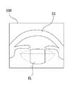
- the controller 80 When alignment with the anterior segment is completed, the controller 80 causes the anterior segment front imaging optical system 30 to image the anterior segment of the eye to be examined. In addition, the control unit 80 captures a cross-sectional image 500 of the eye to be examined by the OCT optical system 100 based on a preset scanning pattern (see FIG. 3). The acquired anterior segment image and cross-sectional image are stored in the memory 85 or the like.
- the control unit 80 calculates the corneal shape of the subject's eye based on the ring index images Q1 and Q2 in the anterior segment image 400 stored in the memory 85.
- the corneal shape is, for example, the corneal curvature radius of the front of the cornea in the strong and weak meridian directions, the astigmatic axis angle of the cornea, and the like.
- the control unit 80 calculates the corneal shape based on the size and shape of the ring index images Q1 and Q2.
- control unit 80 analyzes a cross-sectional image captured using the OCT device 5. For example, the control unit 80 detects the position of the cornea, the lens, and the like by edge detection of the cross-sectional image, and measures the corneal thickness, the anterior chamber depth, and the lens thickness based on the position. Further, the control unit 80 performs circular approximation (or elliptic approximation, conic curve approximation, etc.) of the detected anterior surface or posterior surface of the lens and the radius of curvature of the posterior surface of the cornea, curvature of the anterior surface of the lens, and posterior surface of the lens based on this approximate curve. Measure the curvature etc.
- the control unit 80 calculates the intraocular lens power by partially diverting the known SRK / T equation, Binkhorst equation or the like. For example, the above measurement data is substituted into the SRK / T equation, the Binkhorst equation, and the like.
- the intraocular lens diopter power is calculated using the corneal curvature radius, axial length, post-operative predicted anterior chamber depth (details will be described later), and the like.
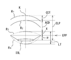
- the predicted postoperative anterior chamber depth ELP pred is calculated by adding the central corneal thickness CCT, the anterior chamber depth ACD, the offset amount X, and the correction amount ⁇ , as shown in FIG. Ru. Therefore, the predicted postoperative anterior chamber depth ELP pred can be expressed as the following equation (2).
- the offset amount X is the distance from the position of the front surface of the lens to the equatorial position (maximum diameter portion of the lens) EPP.
- the equator position is a position where the front surface of the lens and the rear surface of the lens intersect.
- the correction amount ⁇ is the distance from the equatorial position of the lens to the IOL.
- the correction amount ⁇ is affected by the movement of the IOL to the posterior capsule side or the anterior chamber side by receiving pressure from the lens capsule.
- the post-operative predicted anterior chamber depth may be defined from the back of the cornea, but in this case, it is the distance from the front of the cornea to the IOL.
- the distance (quartz of the equatorial lens) h indicates the distance from the optical axis L1 to the intersection point of the approximate circle on the front surface of the lens and the approximate circle on the rear surface of the lens.
- the distance X1 indicates the distance from the lens front surface curvature center O4 in the optical axis L1 to the back surface of the lens.
- the distance X1 ' indicates the distance from the intersection of the approximate circle on the front of the lens and the approximate circle on the rear of the lens to the rear surface of the lens.
- the distance X2 indicates the distance from the lens back surface curvature center O3 in the optical axis L1 to the front surface of the lens.
- the distance X indicates the distance from the intersection of the approximate circle on the front of the lens and the approximate circle on the rear of the lens to the front of the lens, and is an offset amount.
- control unit 80 calculates the offset amount X by substituting the numerical values for the lens front surface curvature radius R 3 , the lens back surface curvature radius R 4 , and the lens thickness LT in Expression (4). Each numerical value is obtained by analyzing a tomographic image.
- the control unit 80 obtains the correction amount ⁇ based on an anterior segment parameter indicating the shape of the anterior segment.
- the anterior segment parameters are, for example, parameters related to the shape of the crystalline lens.
- the anterior segment parameters are, for example, at least one of lens thickness, lens anterior surface curvature, lens posterior surface curvature, lens equatorial position, lens equatorial diameter, anterior chamber depth, corneal thickness, corneal diameter and the like.
- the control unit 80 calculates the correction amount ⁇ using a relational expression between the correction amount ⁇ and the anterior segment parameter.
- This relational expression is acquired, for example, using clinical data of a patient who has inserted an intraocular lens in the past.
- the control unit 80 obtains a measured value of the postoperative anterior chamber depth ELP by analyzing a cross-sectional image of the patient into which the intraocular lens is inserted, and based on the measured value of the postoperative anterior chamber depth ELP, the measured value of the correction amount ⁇ .
- the actual value of the correction amount ⁇ is calculated by subtracting the distance (CCT + ACD + X) from the corneal apex K to the equatorial position EPP measured before the operation from the actual value of the postoperative anterior chamber depth ELP. Then, regression analysis is performed using the measured correction amount ⁇ and the anterior segment shape parameter, and a relational expression is derived from the result. In this embodiment, multiple regression analysis is used.
- the multiple regression analysis is, for example, an analysis method that predicts one variable with a plurality of variables. Multiple regression analysis can be performed by general statistical software or the like. By performing multiple regression analysis using a plurality of clinical data, it is possible to obtain a regression equation of the correction amount ⁇ as in the following equation (5).
- the equation (5) is an example of a regression equation of the correction amount ⁇ .
- the anterior chamber depth ACD, the lens front surface curvature R 3 , and the ratio of the offset amount X to the lens thickness (X / LT) are used as the anterior segment parameters.
- other anterior segment parameters may be used in the regression equation.
- X / LT it is possible to take into consideration the change in the ratio of the lens thickness and the offset amount X depending on the size of the lens to the correction amount ⁇ .
- a combination of a plurality of parameters may be used as the anterior segment parameter.
- control unit 80 calculates the correction amount ⁇ by substituting the anterior chamber depth ACD, the lens front surface curvature R 3 , the offset amount X, and the lens thickness LT into Expression (5).
- control unit 80 substitutes the offset amount X and the correction amount ⁇ calculated by the equations (4) and (5), the central corneal thickness CCT obtained by analyzing the tomographic image, and the anterior chamber depth ACD into the equation (2). Then, the predicted anterior chamber depth ELP pred after surgery is calculated. The control unit 80 calculates the intraocular lens power by substituting the post-operative estimated anterior chamber depth ELP pred estimated in this manner, for example, into AD ′ of Expression (1).
- the intraocular lens power determination device of the present embodiment calculates the correction amount ⁇ based on the anterior segment parameter. Since the correction amount ⁇ varies depending on the shape of the anterior segment of the subject's eye etc., it is possible to estimate an appropriate postoperative predicted anterior chamber depth ELP pred by calculating the correction amount ⁇ based on the anterior segment parameters. . By this, it is possible to select the power of the intraocular lens suitable for the subject eye.
- the IOL parameter (model information) is, for example, at least one of A constant, IOL total length, thickness, front and back surface curvature, material, elastic modulus, optical part diameter, and loop angle.
- a constant is a constant set for each model of IOL based on clinical data.
- the coefficients of the variables in the equation for obtaining the correction amount ⁇ may be set individually for each model of the intraocular lens as in the equation (5).
- the control unit 80 may change the regression equation for obtaining the correction amount ⁇ for each model of the intraocular lens. By this, it is possible to obtain a correction amount ⁇ suitable for each model.
- the relational expression for obtaining the correction amount ⁇ as in the expression (5) may be created by the control unit 80, or may be created in advance by an external computer or the like and recorded in the memory 85 or the like.
- the equatorial position is a position where the front surface of the lens intersects the rear surface of the lens, but the equatorial position may be estimated by another calculation method.
- an optical coherence tomography device for imaging an anterior segment tomographic image acquires a three-dimensional shape image by acquiring an anterior segment tomographic image at a plurality of scanning positions.
- the OCT device 5 is an anterior segment imaging device that acquires a three-dimensional cross-sectional image (three-dimensional anterior segment data) of the anterior segment
- the control unit 80 acquires the three acquired by the anterior segment imaging device.
- the offset distance from the front surface of the lens to the contact point of the chin strip and the lens may be three-dimensionally determined based on the two-dimensional cross-sectional image. In this case, the average of the lens front surface curvature and the lens back surface curvature for each meridian direction in the three-dimensional anterior segment data may be calculated, and the ELP may be calculated based on this.
- an anterior segment imaging device for capturing an anterior segment sectional image an optical coherence tomography device for capturing an anterior segment tomographic image (sectional image) has been exemplified, but the present invention is not limited to this.
- a projection optical system for projecting light emitted from a light source toward the anterior eye of the subject's eye to form a light cutting surface on the anterior eye, and before being acquired by scattering in the anterior eye of the light cutting surface It is sufficient to have a light receiving optical system having a detector for receiving light including scattered light in the eye, and to form an anterior segment cross-sectional image based on a detection signal from the detector. That is, the present invention can also be applied to an apparatus or the like that projects slit light onto the anterior segment of an optometry eye and obtains an anterior segment cross-sectional image with a Shine Pluck Camera.
- the present invention is also applicable to an apparatus for acquiring a three-dimensional shape image of the anterior segment by rotating the Shine Pluck camera or moving it in the horizontal or vertical direction.
- it is possible to obtain the three-dimensional shape image of the anterior segment with high accuracy by performing the shift correction for each predetermined rotation angle, and the accuracy of the measurement value obtained from the three-dimensional shape image is improved.
- the positional deviation in the direction perpendicular to the imaging surface (slit cross section) is detected, and the deviation correction processing is performed based on the detection result.
- the anterior segment cross-sectional image was optically acquired, it is not limited to this.
- any configuration may be used as long as a cross-sectional image of the anterior segment is acquired by detecting reflection information from the anterior segment using an ultrasound probe for B scan.
- IOL calculation formulas such as SRK / T formula and Binkhors formula which are known, were used as a calculation method of IOL frequency, it is not limited to this.
- the IOL power is calculated by the ray tracing method using the postoperative predicted anterior chamber depth ELP, the corneal thickness CCT, the axial length measurement result AL, the corneal curvature radius of the anterior corneal surface, and the corneal curvature radius of the posterior corneal surface.
- IOL powers are calculated by simulating reflection and refraction of light, so the IOL powers can be calculated with high accuracy also by the theoretical formula IOL.
- machine learning may be used to calculate the IOL.
- the cornea curvature radius at the front of the cornea is calculated using the cornea shape measuring device 300, and the cornea curvature radius at the back of the cornea is calculated using the OCT device 5, but It is not limited.
- the radius of curvature of the cornea on the anterior-posterior surface of the cornea may be calculated by the OCT device 5.
- the radius of curvature of the cornea on the anterior and posterior surfaces of the cornea may be treated as the same measurement value. That is, the corneal curvature radius at the front of the cornea calculated by the corneal shape measuring device 300 may be used as the corneal curvature radius at the anterior and posterior surfaces of the cornea.
- corneal topography can also be used as the corneal shape measuring device 300.
- the radius of curvature of the anterior surface of the cornea is calculated, the radius of curvature of the anterior surface of the cornea is calculated from the entire shape of the cornea, so the radius of curvature of the anterior surface of the cornea is accurately calculated. For this reason, when calculating an IOL frequency, it leads to the improvement of the accuracy of IOL frequency calculation.
- the control unit 80 performs an OCT
- the offset amount X may be determined based on positional information of the ciliary body in the anterior segment cross-sectional image acquired by the device 5. For example, the ciliary body (ciliary tip) is detected from the acquired anterior segment tomographic image (an anterior segment cross-sectional image), and the position of the chin zonule is predicted from the detected ciliary body position. Then, the position of the contact portion between the chin band and the lens may be detected from the predicted chin position.
- control The unit 80 processes the contact portion in the anterior segment cross-sectional image acquired by the OCT device 5 to obtain the offset amount X. For example, when a chin zonule is photographed in the anterior segment tomogram (cross-sectional image), the position of the contact portion between the chin zonule and the lens may be detected from the acquired anterior segment tomogram. .
- an anterior segment imaging device for example, an ultrasound B probe, an anterior segment OCT
- control The unit 80 processes the contact portion in the anterior segment cross-sectional image acquired by the OCT device 5 to obtain the offset amount X. For example, when a chin zonule is photographed in the anterior segment tomogram (cross-sectional image), the position of the contact portion between the chin zonule and the lens may be detected from the acquired anterior segment tomogram. .
- an IOL frequency calculation program for performing the functions of the above embodiments is supplied to a system or apparatus via a network or various storage media. Then, a computer (for example, a CPU or the like) of a system or an apparatus can read and execute a program.
- Equation (6) is a equation for calculating the correction amount ⁇ using an anterior segment parameter different from the equation (5) described above.
- Formula (6) is also calculated
- DIA is a lens diameter (a lens equatorial diameter).
- anterior segment parameters generated from the combination of the lens equatorial diameter and the lens thickness are used.
- the ratio of lens thickness to lens equatorial diameter is used. This allows the geometrical features of the lens to be represented by the ratio of thickness to diameter.
- the control unit 80 calculates the correction amount ⁇ based on the shape feature of the crystalline lens, so that, even if the shape of the crystalline lens is different for each subject's eye, it is possible to predict the postoperative condition suitable for each subject's eye You can determine the chamber depth.
Landscapes
- Health & Medical Sciences (AREA)
- Life Sciences & Earth Sciences (AREA)
- Ophthalmology & Optometry (AREA)
- Animal Behavior & Ethology (AREA)
- Veterinary Medicine (AREA)
- Engineering & Computer Science (AREA)
- Biomedical Technology (AREA)
- Heart & Thoracic Surgery (AREA)
- Public Health (AREA)
- General Health & Medical Sciences (AREA)
- Surgery (AREA)
- Physics & Mathematics (AREA)
- Molecular Biology (AREA)
- Medical Informatics (AREA)
- Biophysics (AREA)
- Cardiology (AREA)
- Oral & Maxillofacial Surgery (AREA)
- Transplantation (AREA)
- Vascular Medicine (AREA)
- Eye Examination Apparatus (AREA)
Abstract
適正な術後予測前房深度を推定できる眼内レンズ度数決定装置、および眼内レンズ度数決定プログラムを提供する。被検眼に挿入する眼内レンズの度数を決定する眼内レンズ度数決定装置であって、前記被検眼の前眼部断面画像を撮影する断面撮影手段と、前記眼内レンズの度数を算出する演算制御手段と、を備え、前記演算制御手段は、前記前眼部断面画像を解析することによって前記被検眼の前眼部パラメータを取得し、前記被検眼の水晶体赤道位置から前記眼内レンズまでの距離である補正量を、前記前眼部パラメータを用いて算出し、前記補正量を用いて推定した術後予測前房深度に基づいて前記眼内レンズの度数を算出することを特徴とする。
Description
本開示は、被検眼に挿入する眼内レンズの度数を決定するための眼内レンズ度数決定装置、および眼内レンズ度数決定プログラムに関する。
白内障手術において、水晶体核の除去後に被検眼の眼内に挿入される眼内レンズ(以下、IOL)のパワー(以下、度数)を決定する眼内レンズ度数決定装置が知られている(特許文献1参照)。このような装置では、眼内レンズ度数を決定するために術後予測前房深度(眼内レンズの位置)の推定が行われていた。
しかしながら、推定された術後予測前房深度が実際の術後前房深度と異なる場合があり、眼内レンズを通過した光が網膜に集光せず、適正な視力が得られない可能性があった。
本開示は、従来の問題点に鑑み、適正な術後予測前房深度を推定できる眼内レンズ度数決定装置、および眼内レンズ度数決定プログラムを提供することを技術課題とする。
上記課題を解決するために、本開示は以下のような構成を備えることを特徴とする。
(1) 被検眼に挿入する眼内レンズの度数を決定する眼内レンズ度数決定装置であって、前記被検眼の前眼部断面画像を撮影する断面撮影手段と、前記眼内レンズの度数を算出する演算制御手段と、を備え、前記演算制御手段は、前記前眼部断面画像を解析することによって前記被検眼の前眼部パラメータを取得し、前記被検眼の水晶体赤道位置から前記眼内レンズまでの距離である補正量を、前記前眼部パラメータを用いて算出し、前記補正量を用いて推定した術後予測前房深度に基づいて前記眼内レンズの度数を算出することを特徴とする。
(2) 被検眼に挿入する眼内レンズの度数を決定する眼内レンズ度数決定装置において用いられる眼内レンズ度数決定プログラムであって、前記眼内レンズ度数決定装置のプロセッサによって実行されることで、前記被検眼の前眼部断面画像を撮影する断面撮影ステップと、前記前眼部断面画像を解析することによって前記被検眼の前眼部パラメータを取得する取得ステップと、前記被検眼の水晶体赤道位置から前記眼内レンズまでの距離である補正量を、前記前眼部パラメータを用いて算出し、前記補正量を用いて推定した術後予測前房深度に基づいて前記眼内レンズの度数を算出する算出ステップと、を前記眼内レンズ度数決定装置に実行させることを特徴とする。
(2) 被検眼に挿入する眼内レンズの度数を決定する眼内レンズ度数決定装置において用いられる眼内レンズ度数決定プログラムであって、前記眼内レンズ度数決定装置のプロセッサによって実行されることで、前記被検眼の前眼部断面画像を撮影する断面撮影ステップと、前記前眼部断面画像を解析することによって前記被検眼の前眼部パラメータを取得する取得ステップと、前記被検眼の水晶体赤道位置から前記眼内レンズまでの距離である補正量を、前記前眼部パラメータを用いて算出し、前記補正量を用いて推定した術後予測前房深度に基づいて前記眼内レンズの度数を算出する算出ステップと、を前記眼内レンズ度数決定装置に実行させることを特徴とする。
<実施形態>
以下、本開示に係る実施形態について説明する。本実施形態の眼内レンズ度数決定装置(例えば、眼科撮影装置200)は、被検眼に挿入する眼内レンズの度数を決定するための装置である。眼内レンズ度数決定装置は、例えば、断面撮影部(例えば、OCTデバイス5)と、演算制御部(例えば、制御部80)を備える。断面撮影部は、例えば、被検眼の前眼部断面画像を撮影する。演算制御部は、例えば、眼内レンズの度数を算出する。
以下、本開示に係る実施形態について説明する。本実施形態の眼内レンズ度数決定装置(例えば、眼科撮影装置200)は、被検眼に挿入する眼内レンズの度数を決定するための装置である。眼内レンズ度数決定装置は、例えば、断面撮影部(例えば、OCTデバイス5)と、演算制御部(例えば、制御部80)を備える。断面撮影部は、例えば、被検眼の前眼部断面画像を撮影する。演算制御部は、例えば、眼内レンズの度数を算出する。
演算制御部は、前眼部断面画像を解析することによって被検眼の前眼部パラメータを取得する。前眼部パラメータは、例えば、被検眼の前眼部形状を示すパラメータである。前眼部パラメータは、水晶体形状を示すパラメータを含む。前眼部パラメータは、例えば、水晶体厚、水晶体前面曲率、水晶体後面曲率、水晶体赤道位置、水晶体赤道径、前房深度、角膜厚、角膜径等の少なくともいずれかである。演算制御部は、前眼部パラメータを用いて術後予測前房深度の補正量を算出してもよい。補正量は、例えば、被検眼の水晶体赤道位置から眼内レンズまでの距離である。演算制御部は、算出した補正量を用いて術後予測前房深度を推定し、推定した術後予測前房深度に基づいて、眼内レンズ度数を算出してもよい。これによって、被検眼の前眼部形状に対応した補正量に基づいて、適正な術後予測前房深度を推定し、被検者に対して適正な眼内レンズ度数を算出することができる。
なお、演算制御部は、例えば、前眼部断面画像を解析することによって水晶体赤道位置を特定してもよい。そして、演算制御部は、被検眼の角膜から水晶体赤道位置までの距離に、補正量を足し合わせることによって術後予測前房深度を推定してもよい。
なお、演算制御部は、補正量と前眼部パラメータとの関係式に、前眼部パラメータを代入することによって補正量を算出してもよい。例えば、この関係式は、過去に眼内レンズを挿入した患者の臨床データに基づいて作成されてもよい。例えば、関係式は、補正量の実測値と前眼部パラメータとの回帰分析結果から得られた回帰式であってもよい。この場合、回帰式は、複数の前眼部パラメータを用いた重回帰分析結果によって得られたものでもよい。
なお、前眼部パラメータは、複数のパラメータの組み合わせから新たに生成されたパラメータであってもよい。例えば、前眼部パラメータは、水晶体前面位置から水晶体赤道位置までの距離(オフセット量)と水晶体厚との組み合わせから生成されたパラメータであってもよい。例えば、前眼部パラメータは、水晶体厚に対するオフセット量の割合であってもよい。複数のパラメータを組み合わせた前眼部パラメータを用いることによって、より被検眼に適した術後予測前房深度を算出できる。
なお、演算制御部は、IOL毎に特有のIOLパラメータを用いて術後予測前房深度を推定してもよい。IOLパラメータは、例えば、例えば、A定数、IOLの全長、厚さ、前・後面曲率、材質、弾性率、光学部径、ループ角度の少なくともいずれかである。演算制御部は、術後予測前房深度の推定にIOLパラメータを用いることによって、IOLのモデルに適した術後予測前房深度を推定できる。
なお、演算制御部は、記憶部(例えば、メモリ85)などに記憶された眼内レンズ度数決定プログラムを実行してもよい。眼内レンズ度数決定プログラムは、例えば、断面撮影ステップと、取得ステップと、算出ステップを含む。断面撮影ステップは、例えば、被検眼の前眼部断面画像を撮影するステップである。取得ステップは、例えば、前眼部断面画像を解析することによって被検眼の前眼部パラメータを取得するステップである。算出ステップは、被検眼の水晶体赤道位置から眼内レンズまでの距離である補正量を、前眼部パラメータを用いて算出し、その補正量を用いて推定した術後予測前房深度に基づいて眼内レンズの度数を算出するステップである。
<実施例>
以下、本開示に係る眼科撮影装置200を図面に基づいて説明する。図1は本実施例に係る眼科撮影装置200の光学系について示す概略構成図である。なお、以下の光学系は、図示無き筐体に内蔵されている。また、その筐体は、周知のアライメント移動機構の駆動により、操作部材(例えば、ジョイスティック)を介して被検眼Eに対して3次元的に移動される。なお、以下の説明においては、被検者眼(眼E)の光軸方向をZ方向、水平方向をX方向、鉛直方向をY方向として説明する。眼底の表面方向をXY方向として考えてもよい。
以下、本開示に係る眼科撮影装置200を図面に基づいて説明する。図1は本実施例に係る眼科撮影装置200の光学系について示す概略構成図である。なお、以下の光学系は、図示無き筐体に内蔵されている。また、その筐体は、周知のアライメント移動機構の駆動により、操作部材(例えば、ジョイスティック)を介して被検眼Eに対して3次元的に移動される。なお、以下の説明においては、被検者眼(眼E)の光軸方向をZ方向、水平方向をX方向、鉛直方向をY方向として説明する。眼底の表面方向をXY方向として考えてもよい。
以下の説明においては、光コヒーレンストモグラフィーデバイス(OCTデバイス)5と、角膜形状測定デバイス300と、を備えた眼科撮影装置200を例に挙げて説明する。
OCTデバイス5は、被検眼Eの断面像を撮影するための前眼部撮像デバイスとして用いられる。OCTデバイス5は、眼Eの眼軸長を測定するために用いられてもよい。角膜形状測定デバイス300は、角膜形状を測定するために用いられる。なお、OCTデバイス5は、前眼部断層像(断面像)撮影用の光コヒーレンストモグラフィーデバイスを例にとって説明する。
OCTデバイス5は、干渉光学系(OCT光学系)100を備えている。OCT光学系100は、眼Eに測定光を照射する。OCT光学系100は、前眼部(例えば、角膜、水晶体など)から反射された測定光と,参照光との干渉状態を受光素子(検出器120)によって検出する。OCT光学系100は、前眼部上の撮像位置を変更するため、前眼部における測定光の照射位置を変更する照射位置変更ユニット(例えば、光スキャナ108)を備える。制御部80は、設定された撮像位置情報に基づいて照射位置変更ユニットの動作を制御し、検出器120からの受光信号に基づいて断層画像を取得する。
OCT光学系100は、いわゆる眼科用光断層干渉計(OCT:Optical coherence tomography)の装置構成を持つ。OCT光学系100は、測定光源102から出射された光をカップラー(光分割器)104によって測定光(試料光)と参照光に分割する。そして、OCT光学系100は、測定光学系106によって測定光を前眼部に導き,また、参照光を参照光学系110に導く。その後、前眼部によって反射された測定光と,参照光との合成による干渉光を検出器(受光素子)120に受光させる。
光源102から出射された光は、カップラー104によって測定光束と参照光束に分割される。そして、測定光束は、光ファイバーを通過した後、空気中へ出射される。その光束は、光スキャナ108、及び測定光学系106の他の光学部材を介して前眼部に集光される。そして、前眼部で反射された光は、同様の光路を経て光ファイバーに戻される。
光スキャナ108は、眼E上でXY方向(横断方向)に測定光を走査させる。光スキャナ108は、例えば、2つのガルバノミラーであり、その反射角度が駆動機構109によって任意に調整される。
これにより、光源102から出射された光束はその反射(進行)方向が変化され、眼E上で任意の方向に走査される。これにより、前眼部上における撮像位置が変更される。光スキャナ108としては、光を偏向させる構成であればよい。例えば、反射ミラー(ガルバノミラー、ポリゴンミラー、レゾナントスキャナ)の他、光の進行(偏向)方向を変化させる音響光学素子(AOM)等が用いられる。
参照光学系110は、眼Eでの測定光の反射によって取得される反射光と合成される参照光を生成する。参照光学系110は、マイケルソンタイプであってもよいし、マッハツェンダタイプであっても良い。参照光学系110は、例えば、反射光学系(例えば、参照ミラー)によって形成され、カップラー104からの光を反射光学系により反射することにより再度カップラー104に戻し、検出器120に導く。他の例としては、参照光学系110は、透過光学系(例えば、光ファイバー)によって形成され、カップラー104からの光を戻さず透過させることにより検出器120へと導く。
参照光学系110は、参照光路中の光学部材を移動させることにより、測定光と参照光との光路長差を変更する構成を有する。例えば、参照ミラーが光軸方向に移動される。光路長差を変更するための構成は、測定光学系106の測定光路中に配置されてもよい。
検出器120は、測定光と参照光との干渉状態を検出する。フーリエドメインOCTの場合では、干渉光のスペクトル強度が検出器120によって検出され、スペクトル強度データに対するフーリエ変換によって所定範囲における深さプロファイル(Aスキャン信号)が取得される。ここで、制御部80は、光スキャナ108により測定光を前眼部上で所定の横断方向に走査することにより断層像を取得できる。すなわち、被検眼の前眼部断層像を撮像する。例えば、X方向もしくはY方向に走査することにより、被検眼前眼部のXZ面もしくはYZ面における断層像(前眼部断層像)を取得できる(なお、本実施形態においては、このように測定光を前眼部に対して一次元走査し、断層像を得る方式をBスキャンとする)。なお、取得された前眼部断層像は、制御部80に接続されたメモリ85に記憶される。さらに、測定光をXY方向に二次元的に走査することにより、被検眼前眼部の三次元画像を取得することも可能である。
例えば、フーリエドメインOCTとしては、Spectral-domain OCT(SD-OCT)、Swept-source OCT(SS-OCT)が挙げられる。また、Time-domain OCT(TD-OCT)であってもよい。
SD-OCTの場合、光源102として低コヒーレント光源(広帯域光源)が用いられ、検出器120には、干渉光を各周波数成分(各波長成分)に分光する分光光学系(スペクトルメータ)が設けられる。スペクトルメータは、例えば、回折格子とラインセンサからなる。
SS-OCTの場合、光源102として出射波長を時間的に高速で変化させる波長走査型光源(波長可変光源)が用いられ、検出器120として、例えば、単一の受光素子が設けられる。光源102は、例えば、光源、ファイバーリング共振器、及び波長選択フィルタによって構成される。そして、波長選択フィルタとして、例えば、回折格子とポリゴンミラーの組み合わせ、ファブリー・ペローエタロンを用いたものが挙げられる。
角膜形状測定デバイス300は、ケラト投影光学系50、アライメント投影光学系40、前眼部正面撮像光学系30、に大別される。
ケラト投影光学系50は、測定光軸L1を中心に配置されたリング状の光源51を有し、被検眼角膜にリング指標を投影して角膜形状(曲率、乱視軸角度、等)を測定するために用いられる。なお、光源51には、例えば、赤外光または可視光を発するLEDが使用される。なお、投影光学系50について、光軸L1を中心とする同一円周上に少なくとも3つ以上の点光源が配置されていればよく、間欠的なリング光源であってもよい。さらに、複数のリング指標を投影するプラチド指標投影光学系であってもよい。
アライメント投影光学系40は、光源51の内側に配置され、赤外光を発する投影光源41(例えば、λ=970nm)を有し、被検眼角膜Ecにアライメント指標を投影するために用いられる。そして、角膜Ecに投影されたアライメント指標は、被検眼に対する位置合わせ(例えば、自動アライメント、アライメント検出、手動アライメント、等)に用いられる。本実施形態において、投影光学系50は、被検者眼角膜Ecに対してリング指標を投影する光学系であって、リング指標は、マイヤーリングも兼用する。また、投影光学系40の光源41は、前眼部を斜め方向から赤外光にて照明する前眼部照明を兼用する。なお、投影光学系40において、さらに、角膜Ecに平行光を投影する光学系を設け、投影光学系40による有限光との組合せにより前後のアライメントを行うようにしてもよい。
前眼部正面撮像光学系30は、前眼部正面像を撮像(取得)するために用いられる。前眼部正面撮像光学系30は、ダイクロイックミラー33、対物レンズ47、ダイクロイックミラー62、フィルタ34、撮像レンズ37、二次元撮像素子35、を含み、被検眼の前眼部正面像を撮像するために用いられる。二次元撮像素子35は、被検眼前眼部と略共役な位置に配置されている。
前述の投影光学系40、投影光学系50による前眼部反射光は、ダイクロイックミラー33、対物レンズ47、ダイクロイックミラー62、フィルタ34、及び撮像レンズ37を介して二次元撮像素子35に結像される。
光源1は、固視灯である。また、例えば、光源1から発せられた光の前眼部での反射により取得される前眼部反射光の一部は、ダイクロイックミラー33で反射され、前眼部正面撮像光学系30で結像される。
次に、制御系について説明する。制御部80は、装置全体の制御及び測定結果の算出を行う。制御部80は、OCTデバイス5の各部材、角膜形状測定デバイス300の各部材、モニタ70、操作部84、メモリ85、等と接続されている。
また、操作部84には、操作入力部として、マウス等の汎用インターフェースが用いられてもよいし、その他、タッチパネルが用いられてもよい。
なお、メモリ85には、各種制御プログラムの他、制御部80が前眼部画像解析を行う解析プログラム等が記憶されている。
<制御動作>
以上のような構成を備える装置において、眼内レンズ度数を決定するときの操作と制御動作について説明する。検者は、モニタ70に表示される被検眼のアライメント状態を見ながら、図示なきジョイスティック等の操作手段を用いて、装置を上下左右及び前後方向に移動させ、装置を被検眼Eに対して所定の位置関係に置く。この場合、検者は、固視標を被検眼に固視させる。
以上のような構成を備える装置において、眼内レンズ度数を決定するときの操作と制御動作について説明する。検者は、モニタ70に表示される被検眼のアライメント状態を見ながら、図示なきジョイスティック等の操作手段を用いて、装置を上下左右及び前後方向に移動させ、装置を被検眼Eに対して所定の位置関係に置く。この場合、検者は、固視標を被検眼に固視させる。
アライメントの際には、光源41及び光源51が点灯される。ここで、検者は、図2に示すように、モニタ70に電子的に表示されたレチクルLCと、光源41によるリング指標Q1,Q2が同心円状になるように上下左右のアライメントを行う。これによって、被検眼の角膜頂点に本装置の光軸L1が通るようにXY方向にアライメントされる。また、検者は、リング指標Q1のピントが合うように、前後のアライメントを行う。
前眼部に対するアライメントが完了されると、制御部80は、前眼部正面撮像光学系30によって被検眼の前眼部を撮影する。また、制御部80は、予め設定された走査パターンに基づき、OCT光学系100によって被検眼の断面画像500を撮影する(図3参照)。取得された前眼部画像および断面画像は、メモリ85等に記憶される。
制御部80は、メモリ85に記憶された前眼部画像400におけるリング指標像Q1,Q2に基づいて被検眼の角膜形状をそれぞれ算出する。角膜形状とは、例えば、強主経線方向及び弱主経線方向における角膜前面の角膜曲率半径、角膜の乱視軸角度等である。例えば、制御部80は、リング指標像Q1,Q2の大きさおよび形状に基づいて角膜形状を算出する。
また、制御部80は、OCTデバイス5を用いて撮影された断面画像を解析する。例えば、制御部80は、断面画像のエッジ検出によって角膜、水晶体などの位置を検出し、その位置に基づいて角膜厚、前房深度、水晶体厚を測定する。また、制御部80は、検出された角膜および水晶体の前面または後面を円近似(または楕円近似、コニック曲線近似等)し、この近似曲線に基づいて角膜後面の曲率半径、水晶体前面曲率、水晶体後面曲率等を測定する。
測定および画像解析が完了すると、制御部80は、既知であるSRK/T式、Binkhorst式等を一部流用して眼内レンズ度数を算出する。例えば、SRK/T式、Binkhorst式等に上記の測定データを代入する。SRK/T式(下記の式(1))を用いる場合、角膜曲率半径、眼軸長、術後予測前房深度(詳細は後述する)等を用いて眼内レンズ度数が計算される。

ここで、R:角膜曲率半径[mm](R=(nk-1.000)×1000/K)、nk:検者によって選択された屈折率、LO:AL+RT[mm]、RT:網膜の厚み[mm](RT=0.65696-0.02029×AL)、AL:眼軸長[mm]、AD’:術後予測前房深度の補正値[mm](AD’=H+OF,OF=AD-3.336)、AD:術後予測前房深度[mm](AD=0.62467×A-68.747)、A:A定数、H:角膜高さ[mm](H=R-(R×R-((Cw×Cw)/4))1/2)(ただし、(R×R-((Cw×Cw)/4))<0の場合、H=R)、Cw:角膜幅[mm]、Cw=-5.41+0.58412×LC+0.098×K、LC:眼軸長の補正値[mm](AL≦24.2の場合LC=AL、AL>24.2の場合LC=-3.446+1.716×AL-0.0237×AL2)、DR:術後希望する矯正用レンズの屈折力[D]、LP:移植するIOLの度数[D]、V:頂点距離、na:房水および硝子体の屈折率(=1.336)、nc:角膜の屈折率(=1.333)、ncml: nc-1(=0.333)である。
<術後予測前房深度の算出>
続いて、式(1)に用いられる術後予測前房深度ELPpredの算出について説明する。術後予測前房深度ELPpredは、図4に示すように、角膜頂点Kを基準として、中心角膜厚CCT、前房深度ACD、オフセット量X、補正量αとが足し合わされることによって算出される。したがって、術後予測前房深度ELPpredは次式(2)のように表すことができる。

ここで、オフセット量Xは、水晶体前面の位置から赤道位置(水晶体の最大径部分)EPPまでの距離である。本実施例において、赤道位置は、水晶体前面と水晶体後面とが交差する位置とされる。補正量αは、水晶体赤道位置からIOLまでの距離である。補正量αは、IOLが水晶体嚢から圧力を受けることによる水晶体後嚢側または前房側への移動の影響を受ける。術後予測前房深度としては、角膜裏面から定義される場合もあるが、ここでは、角膜前面からIOLまでの距離とした。
続いて、式(1)に用いられる術後予測前房深度ELPpredの算出について説明する。術後予測前房深度ELPpredは、図4に示すように、角膜頂点Kを基準として、中心角膜厚CCT、前房深度ACD、オフセット量X、補正量αとが足し合わされることによって算出される。したがって、術後予測前房深度ELPpredは次式(2)のように表すことができる。
ここで、オフセット量Xは、水晶体前面の位置から赤道位置(水晶体の最大径部分)EPPまでの距離である。本実施例において、赤道位置は、水晶体前面と水晶体後面とが交差する位置とされる。補正量αは、水晶体赤道位置からIOLまでの距離である。補正量αは、IOLが水晶体嚢から圧力を受けることによる水晶体後嚢側または前房側への移動の影響を受ける。術後予測前房深度としては、角膜裏面から定義される場合もあるが、ここでは、角膜前面からIOLまでの距離とした。
次に、オフセット量Xを算出する方法について説明する。図5において、距離(水晶体赤道半径)hは、光軸L1から水晶体前面の近似円と水晶体後面の近似円との交点までの距離を示している。距離X1は、光軸L1における水晶体前面曲率中心O4から水晶体後面までの距離を示している。距離X1'は、水晶体前面の近似円と水晶体後面の近似円との交点から水晶体後面までの距離を示している。距離X2は、光軸L1における水晶体後面曲率中心O3から水晶体前面までの距離を示している。距離Xは、水晶体前面の近似円と水晶体後面の近似円との交点から水晶体前面までの距離を示しており、オフセット量である。水晶体前面曲率半径R3、水晶体後面曲率半径R4、水晶体厚LTを用いると、ピタゴラスの定理により以下の式(3)が成り立つ。

そして、上記の式(3)において、距離hが同様であるため、これらの式をオフセット量Xについて解くと以下の式(4)が成り立つ。

したがって、制御部80は、式(4)の水晶体前面曲率半径R3、水晶体後面曲率半径R4、水晶体厚LTに各数値を代入することによってオフセット量Xを算出する。各数値は、断層画像の解析によって求められる。
<補正量の算出>
続いて、補正量αを算出する方法について説明する。制御部80は、前眼部の形状を示す前眼部パラメータに基づいて補正量αを求める。前眼部パラメータは、例えば、水晶体形状に関するパラメータである。前眼部パラメータは、例えば、水晶体厚、水晶体前面曲率、水晶体後面曲率、水晶体赤道位置、水晶体赤道径、前房深度、角膜厚、角膜径等の少なくともいずれかである。
続いて、補正量αを算出する方法について説明する。制御部80は、前眼部の形状を示す前眼部パラメータに基づいて補正量αを求める。前眼部パラメータは、例えば、水晶体形状に関するパラメータである。前眼部パラメータは、例えば、水晶体厚、水晶体前面曲率、水晶体後面曲率、水晶体赤道位置、水晶体赤道径、前房深度、角膜厚、角膜径等の少なくともいずれかである。
例えば、制御部80は、補正量αと前眼部パラメータとの関係式を用いて補正量αを算出する。この関係式は、例えば、過去に眼内レンズを挿入した患者の臨床データを用いて取得される。例えば、制御部80は、眼内レンズを挿入した患者の断面画像を解析することで術後前房深度ELPの実測値を求め、術後前房深度ELPの実測値から補正量αの実測値を求める。この場合、術前に測定された角膜頂点Kから赤道位置EPPまでの距離(CCT+ACD+X)を、術後前房深度ELPの実測値から差し引くことによって補正量αの実測値を算出する。そして、実測された補正量αと前眼部形状パラメータとで回帰分析を行い、その結果から関係式を導き出す。本実施例では重回帰分析を用いる。重回帰分析は、例えば、1つの変数を複数の変数で予測する分析方法である。重回帰分析は、一般的な統計ソフトウェア等によって実行可能である。複数の臨床データを用いて重回帰分析を行うことによって、次式(5)のような補正量αの回帰式を得ることができる。式(5)は補正量αの回帰式の一例である。

式(5)の例では、前房深度ACD、水晶体前面曲率R3、水晶体厚に対するオフセット量Xの割合(X/LT)が前眼部パラメータとして用いられている。もちろん、回帰式にはその他の前眼部パラメータが用いられてもよい。なお、X/LTを用いることによって、水晶体の大きさによる水晶体厚とオフセット量Xの比率の変化を補正量αに加味することができる。このように複数のパラメータの組み合わせを前眼部パラメータとして用いてもよい。
例えば、制御部80は、式(5)に前房深度ACD、水晶体前面曲率R3、オフセット量X、水晶体厚LTを代入することによって、補正量αを算出する。
次いで、制御部80は、式(4),(5)によって算出したオフセット量Xと補正量α、断層画像の解析によって得られた中心角膜厚CCTと前房深度ACDを式(2)に代入することによって、術後予測前房深度ELPpredを算出する。制御部80は、このようにして推定した術後予測前房深度ELPpredを、例えば、式(1)のAD'に代入することによって、眼内レンズ度数を計算する。
以上のように、本実施例の眼内レンズ度数決定装置は、前眼部パラメータに基づいて補正量αを算出する。補正量αは、被検眼の前眼部形状などによって変動するため、前眼部パラメータに基づいて補正量αを算出することによって、適正な術後予測前房深度ELPpredを推定することができる。これによって、被検眼に適した眼内レンズの度数を選定することができる。
なお、補正量αは、IOLの形状に関係するため、補正量αを求める回帰式にIOL毎に特有のIOLパラメータを用いてもよい。IOLパラメータ(モデル情報)は、例えば、A定数、IOLの全長、厚さ、前・後面曲率、材質、弾性率、光学部径、ループ角度の少なくともいずれかである。A定数は、臨床データに基づいてIOLのモデル毎に設定された定数である。
なお、式(5)のように、補正量αを求める式の各変数の係数は、眼内レンズのモデル毎に個別に設定されてもよい。例えば、制御部80は、眼内レンズのモデル毎に補正量αを求める回帰式を変更してもよい。これによって、モデル毎に適した補正量αを求めることができる。
なお、式(5)のような補正量αを求める関係式は、制御部80によって作成されてもよいし、外部のコンピュータ等によって予め作成され、メモリ85等に記録されてもよい。
なお、以上の説明において、赤道位置は水晶体前面と水晶体後面とが交差する位置としたが、他の算出方法によって赤道位置を推定してもよい。
なお、本実施例は、前眼部断層像(断面像)撮影用の光コヒーレンストモグラフィーデバイスにおいて、複数の走査位置にて前眼部断層像を取得することにより3次元形状画像を取得する場合においても適用可能である。例えば、OCTデバイス5は、前眼部の3次元断面像(3次元前眼部データ)を取得する前眼部撮像デバイスであって、制御部80は、前眼部撮像デバイスによって取得された3次元断面像に基づいて水晶体前面からチン小帯と水晶体の接点までのオフセット距離を3次元的に求めてもよい。この場合、3次元前眼部データにおける経線方向毎の水晶体前面曲率と水晶体後面曲率の平均を算出し、これに基づいてELPを算出してもよい。
なお、本実施形態においては、前眼部断面像を撮像する前眼部撮像デバイスとして、前眼部断層像(断面像)撮影用の光コヒーレンストモグラフィーデバイスを例に挙げたがこれに限定されない。光源からの出射光を被検眼前眼部に向けて投光し、前眼部上に光切断面を形成させる投光光学系と、光切断面の前眼部での散乱により取得される前眼部散乱光を含む光を受光する検出器を有する受光光学系と、を有し、検出器からの検出信号に基づいて前眼部断面画像を形成する構成であればよい。すなわち、検眼の前眼部にスリット光を投影し、シャインプルークカメラにより前眼部断面画像を得る装置等にも適用可能である。
さらに、シャインプルークカメラを回転させたり、水平または垂直方向に移動させたりすることにより前眼部の3次元形状画像を取得する装置にも適用可能である。この場合、所定の回転角度毎にずれ補正を行うことによって、精度よく前眼部の3次元形状画像を取得することが可能となり、3次元形状画像より取得される測定値の精度が良くなる。この場合、撮像面(スリット断面)に対して垂直な方向の位置ずれが検出され、その検出結果に基づいてずれ補正処理が行われる。
また、上記構成においては、光学的に前眼部断面像を取得したが、これに限定されない。例えば、Bスキャン用の超音波プローブを用いて前眼部からの反射情報を検出することによって前眼部断面像を取得する構成であればよい。
なお、本実施例においては、IOL度数の算出方法として、既知であるSRK/T式、Binkhors式等のIOL計算式を用いたがこれに限定されない。例えば、光線を用いて、光の反射や屈折の様子を幾何学的に追いかけて、光の振る舞いをシミュレーションする光線追跡法によって、IOL度数を算出することもできる。この場合、術後予測前房深度ELP、角膜厚CCT、眼軸長測定結果AL、角膜前面の角膜曲率半径、角膜後面の角膜曲率半径、を用いて光線追跡法によって、IOL度数を算出する。光線追跡法は、光の反射や屈折をシミュレーションによってIOL度数を算出したものであるため、理論式であるIOL計算式によりも精度良くIOL度数を算出することができる。もちろん、機械学習を利用してIOLを計算してもよい。
なお、本実施形態においては、角膜形状測定デバイス300を用いて、角膜前面における角膜曲率半径が算出され、OCTデバイス5を用いて、角膜後面における角膜曲率半径が算出される構成としたがこれに限定されない。OCTデバイス5によって、角膜前後面における角膜曲率半径を算出してもよい。また、角膜前後面の角膜曲率半径を同様の測定値で扱ってもよい。すなわち、角膜形状測定デバイス300で算出した角膜前面における角膜曲率半径が角膜前後面における角膜曲率半径として用いてもよい。
なお、本実施形態において、角膜形状測定デバイス300として、角膜トポグラフィーを用いることもできる。この場合、角膜前面の曲率半径を算出する際に、角膜の全体の形状から角膜前面の曲率半径が算出されるため、角膜前面の曲率半径が精度良く算出される。このため、IOL度数を算出する際に、IOL度数算出の精度向上に繋がる。
なお、OCTデバイス5が毛様体を含む前眼部断面像の画像化が可能な前眼部撮像デバイス(例えば、超音波Bプローブ、前眼部OCT)である場合、制御部80は、OCTデバイス5によって取得された前眼部断面像における毛様体の位置情報に基づいて、オフセット量Xを求めてもよい。例えば、取得された前眼部断層像(前眼部断面像)より、毛様体(毛様体先端部)を検出し、検出した毛様体位置からチン小帯位置を予測する。そして、予測したチン小帯位置からチン小帯と水晶体との接点部分の位置を検出すればよい。
また、OCTデバイス5がチン小帯と水晶体の接点部分を含む前眼部断面像の画像化が可能な前眼部撮像デバイス(例えば、超音波Bプローブ、前眼部OCT)である場合、制御部80は、OCTデバイス5によって取得された前眼部断面像における接点部分を処理してオフセット量Xを求める。例えば、前眼部断層像(断面像)にチン小帯が撮影されていた場合には、取得された前眼部断層像より、チン小帯と水晶体との接点部分の位置を検出すればよい。
なお、本発明においては、本実施形態に記載した装置に限定されない。例えば、上記実施例の機能を行うIOL度数計算プログラムをネットワークや各種記憶媒体を介して、システムあるいは装置に供給する。そして、システムあるいは装置のコンピュータ(例えば、CPU等)がプログラムを読み出し、実行することも可能である。
以下、補正量αを求める計算式の別の例を説明する。次式(6)は、前述の式(5)とは異なる前眼部パラメータを用いた補正量αの計算式である。

式(6)も、式(5)と同様に重回帰分析によって求められる。ここで、DIAは水晶体直径(水晶体赤道径)である。式(6)では、水晶体赤道径と水晶体厚との組み合わせから生成された前眼部パラメータが用いられる。例えば、水晶体赤道径に対する水晶体厚の比が用いられる。これによって、水晶体の形状的特徴を厚みと直径の比率で表すことができる。このように、制御部80は、水晶体の形状的特徴に基づいて補正量αを算出することによって、被検眼毎に水晶体形状が異なる場合であっても、各被検眼に適した術後予測前房深度を求めることができる。
5 光コヒーレンストモグラフィーデバイス
30 前眼部正面撮像光学系
40 アライメント投影光学系
50 ケラト投影光学系
70 モニタ
80 制御部
85 メモリ
84 操作部
30 前眼部正面撮像光学系
40 アライメント投影光学系
50 ケラト投影光学系
70 モニタ
80 制御部
85 メモリ
84 操作部
Claims (14)
- 被検眼に挿入する眼内レンズの度数を決定する眼内レンズ度数決定装置であって、
前記被検眼の前眼部断面画像を撮影する断面撮影手段と、
前記眼内レンズの度数を算出する演算制御手段と、を備え、
前記演算制御手段は、前記前眼部断面画像を解析することによって前記被検眼の前眼部パラメータを取得し、前記被検眼の水晶体赤道位置から前記眼内レンズまでの距離である補正量を、前記前眼部パラメータを用いて算出し、前記補正量を用いて推定した術後予測前房深度に基づいて前記眼内レンズの度数を算出することを特徴とする眼内レンズ度数決定装置。 - 前記演算制御手段は、前記前眼部断面画像から前記水晶体赤道位置を特定し、前記被検眼の角膜から前記水晶体赤道位置までの距離に、前記補正量を足し合わせることによって前記術後予測前房深度を推定することを特徴とする請求項1の眼内レンズ度数決定装置。
- 前記演算制御手段は、前記補正量と前記前眼部パラメータとの関係式に、前記前眼部パラメータを代入することによって前記補正量を算出することを特徴とする請求項1または2の眼内レンズ度数決定装置。
- 前記関係式は、過去に眼内レンズを挿入した患者の臨床データに基づく前記補正量の実測値と前記前眼部パラメータとの重回帰分析結果から得られた回帰式であることを特徴とする請求項3の眼内レンズ度数決定装置。
- 前記前眼部パラメータは水晶体形状に関するパラメータであることを特徴とする請求項1~4のいずれかの眼内レンズ度数決定装置。
- 前記前眼部パラメータは、水晶体厚、水晶体前面曲率、水晶体後面曲率、水晶体赤道位置、水晶体赤道径のいずれかを含むことを特徴とする請求項1~5のいずれかの眼内レンズ度数決定装置。
- 前記前眼部パラメータは、角膜厚、前房深度、角膜径のいずれかを含むことを特徴とする請求項1~6のいずれかの眼内レンズ度数決定装置。
- 前記前眼部パラメータは、複数のパラメータの組み合わせから新たに生成されたパラメータであることを特徴とする請求項1~7のいずれかの眼内レンズ度数決定装置。
- 前記前眼部パラメータは、水晶体前面位置から水晶体赤道位置までの距離と水晶体厚との組み合わせから生成されることを特徴とする請求項8の眼内レンズ度数決定装置。
- 前記前眼部パラメータは、水晶体赤道径と水晶体厚との組み合わせから生成されることを特徴とする請求項8の眼内レンズ度数決定装置。
- 前記演算制御手段は、前記前眼部パラメータと、眼内レンズ毎に特有のIOLパラメータに基づいて、前記術後予測前房深度を推定することを特徴とする請求項1~9のいずれかの眼内レンズ度数決定装置。
- 前記IOLパラメータは、IOL定数であることを特徴とする請求項10の眼内レンズ度数決定装置。
- 前記IOLパラメータは、厚み、度数、曲率、材質のいずれかを含むIOL設計値であることを特徴とする請求項10または11の眼内レンズ度数決定装置。
- 被検眼に挿入する眼内レンズの度数を決定する眼内レンズ度数決定装置において用いられる眼内レンズ度数決定プログラムであって、前記眼内レンズ度数決定装置のプロセッサによって実行されることで、
前記被検眼の前眼部断面画像を撮影する断面撮影ステップと、
前記前眼部断面画像を解析することによって前記被検眼の前眼部パラメータを取得する取得ステップと、
前記被検眼の水晶体赤道位置から前記眼内レンズまでの距離である補正量を、前記前眼部パラメータを用いて算出し、前記補正量を用いて推定した術後予測前房深度に基づいて前記眼内レンズの度数を算出する算出ステップと、
を前記眼内レンズ度数決定装置に実行させることを特徴とする眼内レンズ度数決定プログラム。
Priority Applications (1)
| Application Number | Priority Date | Filing Date | Title |
|---|---|---|---|
| JP2019534513A JPWO2019026862A1 (ja) | 2017-07-31 | 2018-07-30 | 眼内レンズ度数決定装置、および眼内レンズ度数決定プログラム |
Applications Claiming Priority (2)
| Application Number | Priority Date | Filing Date | Title |
|---|---|---|---|
| JP2017-148508 | 2017-07-31 | ||
| JP2017148508 | 2017-07-31 |
Publications (1)
| Publication Number | Publication Date |
|---|---|
| WO2019026862A1 true WO2019026862A1 (ja) | 2019-02-07 |
Family
ID=65233819
Family Applications (1)
| Application Number | Title | Priority Date | Filing Date |
|---|---|---|---|
| PCT/JP2018/028513 Ceased WO2019026862A1 (ja) | 2017-07-31 | 2018-07-30 | 眼内レンズ度数決定装置、および眼内レンズ度数決定プログラム |
Country Status (2)
| Country | Link |
|---|---|
| JP (1) | JPWO2019026862A1 (ja) |
| WO (1) | WO2019026862A1 (ja) |
Cited By (4)
| Publication number | Priority date | Publication date | Assignee | Title |
|---|---|---|---|---|
| US20210186322A1 (en) * | 2019-12-13 | 2021-06-24 | Nidek Co., Ltd. | Ophthalmologic measurement apparatus, ophthalmologic measurement system, and ophthalmologic measurement program |
| CN113440099A (zh) * | 2021-06-07 | 2021-09-28 | 天津市索维电子技术有限公司 | 一种人眼视光综合检查装置和方法 |
| WO2023155509A1 (zh) * | 2022-02-15 | 2023-08-24 | 北京百度网讯科技有限公司 | 一种数据预测方法、装置、电子设备及存储介质 |
| CN119587157A (zh) * | 2024-12-26 | 2025-03-11 | 复旦大学附属眼耳鼻喉科医院 | 马方综合征晶状体不全脱位眼的等效人工晶状体位置和人工晶状体度数预测方法及系统 |
Citations (5)
| Publication number | Priority date | Publication date | Assignee | Title |
|---|---|---|---|---|
| US20050117117A1 (en) * | 2003-12-02 | 2005-06-02 | Dan Bourla | Intraoperative biometry |
| US20090164007A1 (en) * | 2007-12-19 | 2009-06-25 | Wf Systems Llc | Devices and methods for measuring axial distances |
| JP2013094410A (ja) * | 2011-10-31 | 2013-05-20 | Nidek Co Ltd | 眼内レンズ度数決定装置及びプログラム |
| JP2017505698A (ja) * | 2014-02-03 | 2017-02-23 | シャマス,ハンナ | 眼内レンズ度数を決定するシステムおよび方法 |
| JP2018033807A (ja) * | 2016-09-01 | 2018-03-08 | 株式会社ニデック | 眼内レンズ度数決定装置、および眼内レンズ度数決定プログラム |
-
2018
- 2018-07-30 WO PCT/JP2018/028513 patent/WO2019026862A1/ja not_active Ceased
- 2018-07-30 JP JP2019534513A patent/JPWO2019026862A1/ja active Pending
Patent Citations (5)
| Publication number | Priority date | Publication date | Assignee | Title |
|---|---|---|---|---|
| US20050117117A1 (en) * | 2003-12-02 | 2005-06-02 | Dan Bourla | Intraoperative biometry |
| US20090164007A1 (en) * | 2007-12-19 | 2009-06-25 | Wf Systems Llc | Devices and methods for measuring axial distances |
| JP2013094410A (ja) * | 2011-10-31 | 2013-05-20 | Nidek Co Ltd | 眼内レンズ度数決定装置及びプログラム |
| JP2017505698A (ja) * | 2014-02-03 | 2017-02-23 | シャマス,ハンナ | 眼内レンズ度数を決定するシステムおよび方法 |
| JP2018033807A (ja) * | 2016-09-01 | 2018-03-08 | 株式会社ニデック | 眼内レンズ度数決定装置、および眼内レンズ度数決定プログラム |
Cited By (5)
| Publication number | Priority date | Publication date | Assignee | Title |
|---|---|---|---|---|
| US20210186322A1 (en) * | 2019-12-13 | 2021-06-24 | Nidek Co., Ltd. | Ophthalmologic measurement apparatus, ophthalmologic measurement system, and ophthalmologic measurement program |
| US12343082B2 (en) * | 2019-12-13 | 2025-07-01 | Nidek Co., Ltd. | Ophthalmologic measurement apparatus, ophthalmologic measurement system, and ophthalmologic measurement program |
| CN113440099A (zh) * | 2021-06-07 | 2021-09-28 | 天津市索维电子技术有限公司 | 一种人眼视光综合检查装置和方法 |
| WO2023155509A1 (zh) * | 2022-02-15 | 2023-08-24 | 北京百度网讯科技有限公司 | 一种数据预测方法、装置、电子设备及存储介质 |
| CN119587157A (zh) * | 2024-12-26 | 2025-03-11 | 复旦大学附属眼耳鼻喉科医院 | 马方综合征晶状体不全脱位眼的等效人工晶状体位置和人工晶状体度数预测方法及系统 |
Also Published As
| Publication number | Publication date |
|---|---|
| JPWO2019026862A1 (ja) | 2020-07-16 |
Similar Documents
| Publication | Publication Date | Title |
|---|---|---|
| JP5887839B2 (ja) | 眼内レンズ度数決定装置及びプログラム | |
| JP6900647B2 (ja) | 眼科装置、およびiol度数決定プログラム | |
| EP3491996A1 (en) | Ophthalmologic device and iol power determination program | |
| JP5324839B2 (ja) | 光画像計測装置 | |
| US9649024B2 (en) | Method for the model-based determination of the biometry of eyes | |
| JP5179063B2 (ja) | 眼科装置 | |
| US11129529B2 (en) | Ophthalmologic apparatus and method of controlling the same | |
| JP7043759B2 (ja) | 眼科装置、および白内障評価プログラム | |
| US12133687B2 (en) | Ophthalmic apparatus | |
| JP7186587B2 (ja) | 眼科装置 | |
| WO2019026862A1 (ja) | 眼内レンズ度数決定装置、および眼内レンズ度数決定プログラム | |
| JP7236927B2 (ja) | 眼科装置、その制御方法、眼科情報処理装置、その制御方法、プログラム、及び記録媒体 | |
| EP3127472B1 (en) | Method and program for positioning an mage of an object on a tomogram and an optical coherence tomography apparatus therefor | |
| JP2018033807A (ja) | 眼内レンズ度数決定装置、および眼内レンズ度数決定プログラム | |
| JP2020031827A (ja) | 眼科情報処理装置、眼科装置、及び眼科情報処理方法 | |
| JP2019013392A (ja) | 眼科装置、および眼科装置制御プログラム | |
| JP2020151099A (ja) | 眼科装置、その制御方法、眼科情報処理装置、その制御方法、プログラム、及び記録媒体 | |
| JP6052445B2 (ja) | 眼内レンズ度数決定装置及びプログラム | |
| JP6794700B2 (ja) | 前眼部撮影装置、および前眼部解析プログラム | |
| JP2019134908A (ja) | Oct装置、およびoct制御プログラム | |
| JP7292072B2 (ja) | 眼科装置 | |
| JP2020049128A (ja) | 眼内レンズ選択装置、および眼内レンズ選択プログラム | |
| JP2019013391A (ja) | 眼科装置、および眼科装置制御プログラム | |
| JP2022060588A (ja) | 眼科装置、及び眼科装置の制御方法 | |
| JP6662412B2 (ja) | 眼科測定装置 |
Legal Events
| Date | Code | Title | Description |
|---|---|---|---|
| 121 | Ep: the epo has been informed by wipo that ep was designated in this application |
Ref document number: 18841599 Country of ref document: EP Kind code of ref document: A1 |
|
| ENP | Entry into the national phase |
Ref document number: 2019534513 Country of ref document: JP Kind code of ref document: A |
|
| NENP | Non-entry into the national phase |
Ref country code: DE |
|
| 122 | Ep: pct application non-entry in european phase |
Ref document number: 18841599 Country of ref document: EP Kind code of ref document: A1 |