WO2019022115A1 - Ventilateur centrifuge - Google Patents
Ventilateur centrifuge Download PDFInfo
- Publication number
- WO2019022115A1 WO2019022115A1 PCT/JP2018/027834 JP2018027834W WO2019022115A1 WO 2019022115 A1 WO2019022115 A1 WO 2019022115A1 JP 2018027834 W JP2018027834 W JP 2018027834W WO 2019022115 A1 WO2019022115 A1 WO 2019022115A1
- Authority
- WO
- WIPO (PCT)
- Prior art keywords
- air
- housing
- inlet
- region
- outside
- Prior art date
Links
Images


Classifications
-
- B—PERFORMING OPERATIONS; TRANSPORTING
- B60—VEHICLES IN GENERAL
- B60H—ARRANGEMENTS OF HEATING, COOLING, VENTILATING OR OTHER AIR-TREATING DEVICES SPECIALLY ADAPTED FOR PASSENGER OR GOODS SPACES OF VEHICLES
- B60H1/00—Heating, cooling or ventilating [HVAC] devices
-
- B—PERFORMING OPERATIONS; TRANSPORTING
- B60—VEHICLES IN GENERAL
- B60H—ARRANGEMENTS OF HEATING, COOLING, VENTILATING OR OTHER AIR-TREATING DEVICES SPECIALLY ADAPTED FOR PASSENGER OR GOODS SPACES OF VEHICLES
- B60H3/00—Other air-treating devices
- B60H3/06—Filtering
-
- F—MECHANICAL ENGINEERING; LIGHTING; HEATING; WEAPONS; BLASTING
- F04—POSITIVE - DISPLACEMENT MACHINES FOR LIQUIDS; PUMPS FOR LIQUIDS OR ELASTIC FLUIDS
- F04D—NON-POSITIVE-DISPLACEMENT PUMPS
- F04D29/00—Details, component parts, or accessories
- F04D29/26—Rotors specially for elastic fluids
- F04D29/28—Rotors specially for elastic fluids for centrifugal or helico-centrifugal pumps for radial-flow or helico-centrifugal pumps
-
- F—MECHANICAL ENGINEERING; LIGHTING; HEATING; WEAPONS; BLASTING
- F04—POSITIVE - DISPLACEMENT MACHINES FOR LIQUIDS; PUMPS FOR LIQUIDS OR ELASTIC FLUIDS
- F04D—NON-POSITIVE-DISPLACEMENT PUMPS
- F04D29/00—Details, component parts, or accessories
- F04D29/40—Casings; Connections of working fluid
- F04D29/42—Casings; Connections of working fluid for radial or helico-centrifugal pumps
- F04D29/44—Fluid-guiding means, e.g. diffusers
-
- F—MECHANICAL ENGINEERING; LIGHTING; HEATING; WEAPONS; BLASTING
- F04—POSITIVE - DISPLACEMENT MACHINES FOR LIQUIDS; PUMPS FOR LIQUIDS OR ELASTIC FLUIDS
- F04D—NON-POSITIVE-DISPLACEMENT PUMPS
- F04D29/00—Details, component parts, or accessories
- F04D29/70—Suction grids; Strainers; Dust separation; Cleaning
Definitions
- the present invention relates to a centrifugal fan for a two-layer flow vehicle air conditioner.
- centrifugal blower suitable for a two-layer flow type vehicle air conditioner
- the centrifugal fan has a scroll housing having upper and lower passages separated from each other, and a separation cylinder inserted in the scroll housing.
- the inside air sucked at a sufficient flow rate may enter the outside air upper passage when, for example, it is blown out from the impeller into the lower passage of the scroll housing There is sex.
- the anti-fogging of the window glass at the time of heating which is the main purpose of adopting the inside / outside air two-layer flow mode, can not be sufficiently achieved.
- An object of the present invention is to provide a centrifugal fan capable of suppressing the air flow resistance of the outside air from the outside air introduction port of the air intake housing to the scroll housing in the inside / outside air two-layer flow mode.
- a single suction type centrifugal fan for a vehicle comprising: a motor; and a plurality of wings forming a circumferential wing row, wherein the motor rotates around a rotation axis.
- An impeller that is driven and blows air radially inward from the one end side in the axial direction into the space in the radial direction of the blade row, an internal space that accommodates the impeller, and the axial direction
- a scroll housing having a suction port opening at one end and a discharge port opening in the circumferential direction; an inner circumferential surface of the scroll housing in the inner space of the scroll housing and an outer circumferential surface of the impeller And an inner wall of the discharge opening in the axial direction to form a first air flow passage and a second air flow passage, and an inlet end located outside the scroll housing And the feather
- a separate cylinder having an outlet end located radially inward of the cascade of the car, and extending from the inlet end to the outlet end radially inward of the suction port, the scroll
- the flow of air drawn into the housing is divided into a first air flow passing outside the separation cylinder and a second air flow passing inside the separation cylinder, and the outlet end is the The separation cylinder configured to guide the first
- a first internal air inlet for introducing internal air into the air intake housing when operated in the flow mode, the external air inlet being positioned above the first internal air inlet, and the centrifugal fan being A centrifugal fan is provided, in which ambient air flows from the ambient air inlet to the first region and ambient air flows from the first ambient air inlet to the second region when operated in a laminar flow mode.
- the turning of the outside air can be suppressed to a low level at least in the section from the outside air introduction port of the air intake housing to the suction port of the scroll housing. Therefore, the air flow resistance in the section can be suppressed to a low level.
- FIG. 6 is a cross-sectional view taken along the line II-II in FIGS. 1, 4 and 5;
- FIG. 6 is a cross-sectional view taken along the line III-III in FIGS. 1, 4 and 5;
- It is a meridional sectional view of a centrifugal blower according to another embodiment (the second embodiment), and is a meridional sectional view obtained by cutting the centrifugal blower on the same vertical plane as that of FIG.
- centrifugal blower for a vehicle according to the present invention
- R means the right side of the vehicle
- L the left side of the vehicle
- Fr the front of the vehicle
- Rr the rear of the vehicle
- U the upper side of the vehicle
- D the lower side of the vehicle.
- the centrifugal blower is often installed in a vehicle in the illustrated direction, but the installation direction of the centrifugal blower is not limited to the illustrated example, and may be slightly inclined, for example, with respect to the illustrated direction.
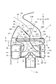
- the centrifugal fan 1 shown in FIG. 1 is a single suction type centrifugal fan.
- the centrifugal fan 1 has an impeller 2.
- the impeller 2 has a plurality of vanes 3 forming a cascade 3A aligned in the circumferential direction on the outer peripheral portion thereof.
- the impeller 2 is rotationally driven about the rotation axis Ax by the motor 13 and directed radially outward to the air sucked into the space radially inward of the cascade of the impeller 2 from the axially upper side (one end side in the axial direction) Blow out.
- the direction of the rotation axis Ax is referred to as the axial direction or the vertical direction, and the upper side and the lower side in FIG. 1, FIG. 4 and FIG. It is called "side".
- this does not necessarily mean that the direction of the rotation axis Ax coincides with the vertical direction when the air conditioner is actually incorporated into a vehicle.
- the direction of the radius of a circle drawn on a plane orthogonal to the rotation axis Ax centering on any point on the rotation axis Ax is referred to as the radial direction
- the circumferential direction of the circle is called circumferential direction or circumferential direction.
- the impeller 2 includes an inner deflection member 9 integrally formed with the impeller 2.
- the inner deflection member 9 may be called a cone.
- the inner deflection member 9 is a rotary body in a geometrical sense, and has a side peripheral portion 10 and a disc-shaped central portion 11. At the central portion 11, the rotating shaft 12 of the motor 13 is connected to the impeller 2.
- the side peripheral portion 10 is curved so that the contour line in the meridional section of the outer peripheral surface of the side peripheral portion 10 becomes steeper as it approaches the central portion 11.
- the side circumferential portion 10 has a case where the contour line in the meridional section of the outer circumferential surface of the side circumferential portion 10 is not curved from the central portion 11 toward the cascade 3A (the cross section is linear) There is also.
- the impeller 2 is accommodated in an internal space of the scroll housing 17.
- the scroll housing 17 has a suction port 22 opening upward in the axial direction, and a discharge port 170 (see FIG. 2). As shown in FIG. 2, when the scroll housing 17 is viewed from the axial direction, the discharge port 170 extends in a direction substantially tangential to the outer peripheral surface of the scroll housing 17. The outlet 170 is not visible in FIG.
- the scroll housing 17 has a partition wall 20 extending radially inward from an outer peripheral wall 17A of the scroll housing 17.
- the partition wall 20 divides an area between the inner peripheral surface of the scroll housing 17 and the outer peripheral surface of the impeller 2 in the internal space of the scroll housing 17 in the axial direction (up and down) to An upper first air flow passage 18 and a lower second air flow passage 19 extending in the circumferential direction along the outer peripheral wall 17A are formed.
- the separation cylinder 14 is inserted into the scroll housing 17 via the suction port 22.
- the cross section (meaning the cross section orthogonal to the rotation axis Ax) of the upper end portion 24 (the inlet side end portion) of the separation cylinder 14 is substantially rectangular.
- the cross section of the central portion 15 of the separation cylinder 14 is circular (or generally circular).
- the sectional shape of the separation cylinder 14 smoothly changes from a rectangular shape to a circular shape as the upper end 24 approaches the central portion 15.
- the cross-sectional shape of the separation cylinder 14 is circular (or generally circular) from the central portion 15 to the lower portion 16 of the separation cylinder 14, and the radius of the circle gradually increases toward the lower portion 16.
- the lower portion 16 of the separation cylinder 14 has a flared shape that increases in diameter toward the lower end.
- the position of the center of the cross section of the separation cylinder 14 smoothly changes from the upper end 24 to the lower portion 16 (outlet side end), and is located on the rotation axis Ax at the lowermost end (outlet side end) of the lower portion 16 There is.
- the central portion 15 to the lower portion 16 of the separation cylinder 14 extend through the space radially inward of the suction port 22 to the internal space of the impeller 2.
- the upper end portion 24 of the separation cylinder 14 is located outside the scroll housing 17 (above the suction port 22 in the axial direction).
- the lower end of the separation cylinder 14 is located in the vicinity of the wing 3 of the impeller 2 at an axial height substantially the same as the partition wall 20 of the scroll housing 17.
- the separation cylinder 14 It is impossible or, if possible, very difficult to integrally mold the separation cylinder 14 having the illustrated shape by resin injection molding technology. Therefore, it is preferable to manufacture the separation cylinder 14 by connecting two or more pieces separately injection-molded by a technique such as bonding or fitting.
- the separation cylinder 14 divides the flow of air drawn into the scroll housing 17 into a first air flow passing outside the separation cylinder 14 and a second air flow passing inside the separation cylinder 14.
- the first air flow passes through a ring-shaped region outside the outer peripheral surface of the separation cylinder 14 in the suction port 22 of the scroll housing 17 and is applied to the upper half of the blade row of the impeller 2 (portion close to the suction port 22) To flow.
- the second air flow enters the inside of the separation cylinder 14 from the upper end of the separation cylinder 14 and flows into the lower half of the cascade of the impeller 2 (a portion far from the suction port 22).
- the ring-like region outside the outer peripheral surface of the separation cylinder 14 in the suction port 22 of the scroll housing 17 is the first suction opening of the scroll housing 17 and the opening of the upper end of the separation cylinder 14 is the second suction opening of the scroll housing 17 It can also be regarded as.
- An air intake housing 21A is connected to the scroll housing 17.
- the scroll housing 17 and the air intake housing 21A may be integrally formed, or may be separately manufactured and then connected by a method such as screwing, bonding, or fitting.
- the scroll housing 17 and the air intake housing 21 form part of an air conditioner casing.
- the air intake housing 21A has an outside air introduction port 25 and an inside air introduction port (first inside air introduction port) 26A.
- the outside air inlet 25 and the inside air inlet 26A both open generally forward.
- the outside air inlet 25 is above the inside air inlet 26A.
- the outside air introduction port 25 is connected to or in the vicinity of the exit 28 of the outside air introduction path provided in the vehicle partition 27 that divides the engine room of the vehicle and the compartment. Therefore, the outside air AE (air taken in from the outside of the vehicle) can be introduced into the air intake housing 21A through the outside air introduction port 25.
- the inside air introduction path 26A opens in the space of the vehicle compartment separated from the engine room by the vehicle bulkhead 27. Therefore, the inside air AR (air in the passenger compartment) can be introduced into the air intake housing 21A through the inside air introduction port 26A.
- FIG. 3 shows a cross section (a cross section orthogonal to the rotation axis Ax) of the air intake housing 21A including the upper end (the inlet side end) of the separation cylinder 14.
- This cross section can be divided into the front area 212 (second area) and the rear area 211 (first area) by the virtual dividing line DL.
- the front region 212 substantially coincides with the opening region 240 surrounded by the end edge of the upper end portion 24 of the separating cylinder 14.
- the rear area 211 is an area behind the opening area 240 in the cross section of the air intake housing 21A.
- the area ratio of the front region 212 to the rear region 211 can be 5: 5. However, in order to promote the introduction of the outside air AE, the area of the rear region 211 may be larger than that of the front region 212.
- a housing partition 40 is provided in the air intake housing 21A.
- the housing partition 40 separates a first passage T1 connecting the outside air inlet 25 and the rear region 211 (see also FIG. 3) and a second passage T2 connecting the inside air inlet 26A and the front region 212. It is separated.
- the first passage T1 and the second passage T2 have a substantially rectangular cross section having a long side extending in the lateral direction and a short side orthogonal thereto.
- the first passage T1 (also the second passage T2) maintains the length ratio of the long side to the short side of the rear region 211 (front region 212) in FIG. 3 or changes the above ratio. It extends from the generally rectangular outside air inlet 25 (inside air inlet 26A) to the rear region 211 (front region 212).
- the first passage T1 is an air passage through which the outside air AE flows
- the second passage T2 is an air passage through which the inside air AR flows.
- the air flow path of the outside air AE from the outside air inlet 25 to the rear region 211 is inclined and extends downward and backward as it goes downstream from the outside air inlet 25 And, it extends above and to the rear of the air flow path of the inside air AR from the inside air inlet 26A to the second region 212.
- the rear wall 29 of the air intake housing 21A is curved so as to be convex upward and rearward. Therefore, the inclination angle ⁇ (see FIG. 1) with respect to the horizontal plane of the air flow path of the outside air AE from the outside air introduction port 25 to the rear region 211 gradually increases toward the downstream side. That is, the flow direction of the outside air AE changes its direction gradually as it goes downstream, and a sudden change of direction of the outside air AE does not occur. That is, the increase in the air flow resistance of the outside air AE due to the change of direction is very small, so that a sufficient amount of the outside air AE can be introduced into the scroll housing 17 particularly in the two-layer flow mode.
- FIG. 1 shows that the first switching door 42 is in the neutral position (two-layer flow mode position) in order to operate the centrifugal blower in the two-layer flow mode.
- the outside air AE which has flowed into the rear region 211 (see also FIG. 3) flows into the scroll housing 17 through the outside of the separation cylinder 14. It passes through the upper half and is blown out to the first air flow passage 18. At this time, the main flow of the outside air AE that has passed through the back side area 211 flows toward the back side area of the suction port 22 of the scroll housing 17 (see FIG. 1). It flows into the scroll housing 17 from the rear region of the mouth 22. However, a part of the outside air AE flows to the front side through the periphery of the separation cylinder 14 and flows into the scroll housing 17 from the front side area of the suction port 22.
- the inside air AR that has flowed into the front area 212 of FIG. 3 flows into the scroll housing 17 through the inside of the separation cylinder 14, passes through the lower half of the impeller 2 and blows out into the second air flow path 19. Be done.
- the first switching door 42 blocks the outside air mode position for operating the centrifugal blower in the outside air mode (about 80 degrees clockwise from the neutral position in FIG. A position shown by an alternate long and short dash line, and an inside air mode position for operating in an inside air mode (a position shown by an alternate long and short dash line rotating about 100 degrees counterclockwise from the neutral position in FIG. It can also be taken.
- the outside air introduction port 25 communicates with the rear side area 211 and the front side area 212 in FIG. 3 while the communication between the inside air introduction port 26A and the rear side area 211 and the front side area 212 is cut off.
- the inside air introduction port 26A communicates with the rear side area 211 and the front side area 212 of FIG. 3, while the outside air introduction port 25 is disconnected from the rear side area 211 and the front side area 212.
- a filter 35 is provided on the upper side near the upper end portion 24 of the separation cylinder 14. Looking at the filter 35 from the upstream side with respect to the flow direction of the air, the filter 35 covers the front area 212 and the rear area 211 of the cross section of FIG. 3 described above, dust contained in the air which is going to pass through these areas Remove contaminants such as particles and offensive odors.
- the filter 35 has a partition plate 35S extending in parallel with the virtual dividing line DL described above.
- this partition plate 35S it is possible to prevent or suppress mixing of the inside air and the outside air in the vicinity of the center of the filter 35 when passing through the filter 35.
- the contour line 14P on the rear side of the separation cylinder 14 is inclined so as to be more rearward as it goes downward from the upper end to the lower end.
- the outside air AE flowing from the vicinity of the upper end 24 (inlet side end) of the separation cylinder 14 into the scroll housing 17 is smoothly and gradually turned to be directed radially outward of the impeller 2. This also facilitates the flow of the outside air AE, which is advantageous for introducing a sufficient amount of outside air AE into the scroll housing 17.
- FIG. 2 which is a cross section including the peripheral edge 22e which is orthogonal to the axis Ax and which is the inner peripheral edge of the suction port 22, the gap between the peripheral edge 22e and the outer peripheral surface of the separation cylinder 14 is a gap G1 on the rear side. Is larger than the front gap G2.
- a large amount of outside air AE flows to the rear portion of the suction port 22.
- a larger amount of outside air AE can be taken into the scroll housing 17 by increasing the rear gap G1 as described above.
- the various geometric features of the components of the centrifugal fan described above allow the outside air AE to flow efficiently into the scroll housing 17. Therefore, when the centrifugal blower is operated in the two-layer flow mode, it is possible to prevent or suppress the mixing of the inside air AR into the outside air AE. For this reason, for example, the fog prevention of the window glass at the time of heating can be achieved reliably.
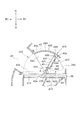
- FIG. 4 Another embodiment (second embodiment) will be described with reference to FIG. 4, members that are the same as or similar to the members shown in FIG. 1 are given the same or similar reference numerals, and redundant description will be omitted.
- an air intake housing 21B is provided in place of the air intake housing 21A.
- a second inside air introduction port 26B is formed in the rear wall 29 of the air intake housing 21B.
- a second switching door 43 which is driven by an actuator (not shown) and which pivots about a pivot shaft 43a extending in the left-right direction is provided.
- the second switching door 43 can move between a position (first position) shown in FIG. 4 and a position (second position) rotated approximately 60 degrees counterclockwise from the position shown in FIG.
- first position the outside air inlet 25 and the rear region 211 communicate with each other, and the communication between the second inside air inlet 26B and the rear region 211 is cut off.
- second position the communication between the outside air introduction port 25 and the rear area 211 is cut off, and the second inside air introduction port 26B is in communication with the rear area 211.
- the first switching door 42 opens the first inside air introduction port 26A and closes the opening 41 of the housing partition 40 (corresponding to the neutral position in the first embodiment); It can move between the 2nd position (equivalent to the open air mode position in a 1st embodiment) which closes opening 26A and opens opening 41 of housing partition 40.
- the first switching door 42 of the second embodiment can not be located at a position corresponding to the inside air mode position in the first embodiment.
- the first switching door 42 is positioned at the first position and the second switching door 43 is positioned at the first position. To position. That is, at this time, the inside air AR introduced from the first inside air introduction port 26A flows to the front area 212, and the outside air AE introduced from the outside air introduction port 25 flows to the rear area 211.
- the first switching door 42 is at the first position, and the second switching door 43 is at the second position. That is, at this time, the inside air AR introduced from the first inside air introduction port 26A flows to the front region 212, and the inside air AR introduced from the second inside air introduction port 26B flows to the rear region 211.
- the first switching door 42 is at the second position, and the second switching door 43 is at the first position. That is, at this time, the outside air AE introduced from the outside air introduction port 25 flows to the front area 212 and the rear area 211.
- the second switching door 43 When viewed in the cross section of FIG. 4, the second switching door 43 has an air guiding surface 43 g curved so as to be convex upward and backward when in the first position.
- the profile of the combination of the rear wall of the air intake housing 21B and the second switching door 43 is the air in the first embodiment, as viewed in the cross section of FIG.
- the outline of the rear wall of the intake housing 21A is substantially the same. Therefore, when the centrifugal blower is operated in the two-layer flow mode, the outside air AE introduced from the outside air introduction port 25 flows while changing its direction smoothly. For this reason, the increase in ventilation resistance of the outside air AE caused by the change of direction can be suppressed to a very small value. Therefore, also in the second embodiment, a sufficient amount of outside air AE can be introduced into the scroll housing 17 as in the first embodiment.
- the air guiding surface 43g of the second switching door 43 has a shape corresponding to a part of the side surface of a cylinder whose center axis is the pivot shaft 43a.
- the air guiding surface 43g is a surface provided at a position spaced apart from the turning shaft 43a by a predetermined distance.
- FIG. 5 the same or similar reference numerals are given to members that are the same as or similar to the members shown in FIG.
- an air intake housing 21C is provided instead of the air intake housing 21A.
- a second inside air introduction port 26B similar to that of the second embodiment is formed.
- a second switching door 44 which is driven by an actuator (not shown) and pivots about a pivot shaft 44a extending in the left-right direction is provided at the second inside air introduction port 26B.
- the second switching door 44 can move between a position (first position) shown in FIG. 5 and a position (second position) rotated approximately 50 degrees clockwise from the position shown in FIG.
- first position the outside air inlet 25 and the rear region 211 communicate with each other, and the communication between the second inside air inlet 26B and the rear region 211 is cut off.
- second switching door 44 is in the second position, the communication between the outside air introduction port 25 and the rear area 211 is cut off, and the second inside air introduction port 26B is in communication with the rear area 211.
- the first switching door 42 in the third embodiment has the same configuration as the first switching door 42 shown in FIG. 1 and, like the first switching door 42 shown in FIG. Three positions can be taken: position, inside air mode position, and outside air mode position.
- the centrifugal blower when the centrifugal blower is operated in the two-layer flow mode, as shown in FIG. 5, the first switching door 42 is at the neutral position and the second switching door 43 is at the first position. Do. That is, at this time, the inside air AR introduced from the first inside air introduction port 26A flows to the front area 212, and the outside air AE introduced from the outside air introduction port 25 flows to the rear area 211.
- the first switching door 42 When the centrifugal blower is operated in the inside air mode, the first switching door 42 is located at the inside air mode position, and the second switching door 43 is located at the second position. That is, at this time, the inside air AR introduced from the first inside air introduction port 26A flows to the front region 212, and the inside air AR introduced from the second inside air introduction port 26B flows to the rear region 211.
- the first switching door 42 may be located at the neutral position.
- the first switching door 42 When the centrifugal blower is operated in the open air mode, the first switching door 42 is positioned at the open air mode position, and the second switching door 44 is positioned at the first position. That is, at this time, the outside air AE introduced from the outside air introduction port 25 flows to the front area 212 and the rear area 211.
- the second switching door 44 in the first position is also an air guiding surface curved to be convex upward and backward, as viewed from the cross section of FIG. 5. It has 44g. That is, when the second switching door 44 is located at the first position, the profile of the combination of the rear wall of the air intake housing 21B and the second switching door 44 is the first embodiment, as viewed in the cross section of FIG. The outline of the rear wall of the air intake housing 21A in FIG. Therefore, the second switching door 44 plays the same role as the second switching door 43.
- the same effects as those of the first embodiment can be achieved.
- the second inside air introduction port 26B in addition to the first inside air introduction port 26A, a sufficient amount of inside air can be transmitted through the rear area 211 in the inside air mode. Can be taken into the scroll housing 17.
- the first switching door 42 since the first switching door 42 does not have to be located at the inside air mode position as in the first and third embodiments, in the first position in the inside / outside air two-layer flow mode The first switching door 42 can reliably close the opening 41 of the housing partition 40. As a result, it is possible to more reliably prevent the inside air from being mixed with the outside air in the inside / outside air two-layer flow mode.
- FIG. 6A is substantially identical to the upper half of FIG. 4 except that an explanatory reference numeral is added.
- the first switching door 42 is formed as a cantilever door.
- cantilevered door means a door with a single wall involved in the opening and closing of the air inlet, extending in one direction from the rotational axis (pivot 42a). Note that a door with two walls involved in the opening and closing of the air inlets extending in opposite directions from the pivot is called a “butterfly door” and is different from a cantilever door.
- the second switching door 43 is formed as a rotary door.
- rotary door means a door having a curved wall (43b) (a wall involved in the opening and closing of the air inlet) remote from the axis of rotation (pivot 43a).
- the first switching door 42 is referred to as a "cantilever door 42"
- the second switching door 43 is referred to as a "rotary door 43”.
- the rotary door 43 itself has a fan-like shape as a whole.
- the rotary door 43 has a pair of fan-shaped side walls (which correspond to the bottom of the fan in geometric terms) connected to the pivot shaft 43a, and a peripheral wall 43b connected to the side wall 43c (which is for the fan) (Corresponding to a curved side of one of the three sides as a geometrical term).
- no wall is present in portions corresponding to the two flat sides as geometrical terms for the fan.
- the rotary door 43 is provided so as to block the communication between at least the outside air introduction port 25 and the first area 211, and the cantilever door 42 is At least the communication between the inside air inlet 26A and the second region 212 can be shut off.
- the rotary door 43 pivots about the first pivot axis 43 a so as to draw a pivoting path having the shape of the first fan 430.
- the central angle of the bottom of the first fan 430 (bottom in geometrical terms) is shown as ⁇ 43 in FIG. 6A.
- the cantilever door 42 pivots about a second pivot axis 42 a parallel to the first pivot axis 43 a so as to draw a pivot path having the shape of a second fan 420.
- the central angle of the bottom (bottom in geometrical terms) of the second fan 420 is indicated by ⁇ 42 in FIG. 6A.
- fan means a straight cylinder having a fan-shaped bottom. That is, a fan is two base surfaces of two mutually parallel fan-shaped (meaning a figure surrounded by two radii of a circle and an arc between them) and two flat sides (which are rectangular or square) And one curved side (which has a shape corresponding to a part of the side of the cylinder).
- the first fan 430 formed by the rotary door 43 and the second fan 420 formed by the cantilever door 42 satisfy the following relationship 1 and relationship 2.
- (Relation 1) One of the two flat side surfaces 431 and 432 of the first sector 430 and one of the two flat side surfaces 421 and 422 of the second sector 420 are close to each other.
- (Relationship 2) The curve of the curved side surface 433 of the first sector 430 at the first connection portion 434 where the curved side surface 433 of the first sector 430 and the flat side surface 431 of the first sector 430 are connected.
- the second side surface 423 of the second sector 420 at the second connection portion 424 where the curved side surface 423 of the second sector 420 and the flat side surface 421 of the second sector 420 are connected. The directions of are opposite to each other.
- one flat side surface 431 of the first fan 430 and one flat side 421 of the second fan 420 are close to each other, and They are facing each other with a (small) gap therebetween. In this case, the first fan 430 and the second fan 420 are separated.
- a space to be secured in the air intake housing 21B for installing the rotary door 43 and the cantilever door 42. (Hereafter, it is called "door installation space") can be made small.
- the door installation space is the shortest including the bottom of the sector of the first sector 430 and the bottom of the sector of the second sector 420 when viewed in the direction of the first pivot 43a (or the second axis 42a). It can be grasped as the size of the space which is roughly proportional to the area of the area surrounded by the closed line of.
- first fan 430 and the second fan 420 further satisfy the following relationship 3: (Relationship 3)
- the distance from the first connection portion 434 where the curved side surface 433 of the first fan 430 to the one flat side 431 of the first fan 430 is connected is The second connecting portion 434 is smaller than the distance from the first connecting portion 434 to the second connecting portion 424 where the curved side surface 423 of the second fan 420 and the flat side 421 of the second fan 420 are connected.
- the distance from the connection portion 424 to the first pivot axis 43 a is smaller than the distance from the second connection portion 424 to the first connection portion 434.
- the establishment of the relationship 3 means that the side surface 431 and the side surface 421 overlap with a sufficiently large overlapping margin when viewed from the normal direction of the side surface 431 (or the side surface 421). ing. This can further reduce the door installation space.
- first fan 430 and the second fan 420 further satisfy the following relationship.
- Relationship 4 The first fan 430 is in a region not lower than the first pivot 43a, and the second fan 420 is in a region not higher than the second pivot 42a.
- the door installation space can be further reduced by defining the turning range of the first fan 430 and the second fan 420.
- the relation 4 can also be defined in relation to the air inflow surface of the filter 35 (in the illustrated embodiment the upper face of the filter 35), in which case the relation 4 can be rewritten as follows.
- (Relationship 4 ′) The first fan 430 is in a region closer to the air inflow surface of the filter 35 than the first pivot axis 43a, and the second fan 420 is air inflow of the filter 35 than the second pivot axis 42a. It is in the area not far from the surface.
- FIGS. 7A and 7B show a modification of the second embodiment.
- one flat side 431 of the first fan 430 and one flat side 421 of the second fan 420 are close to each other (relation 1), and the first fan 430 and the first fan 430 are the same.
- the two fans 420 partially overlap.
- the relationship 2 is the same as that of the second embodiment shown in FIGS. 6A and 6B.
- the cantilever door 42 can be turned to the position where the tip of the cantilever door 42 enters the inside of the first fan 430.
- the rotary door 43 no wall is present in portions corresponding to two flat sides in the geometric term of the fan. Therefore, as shown in FIGS. 7A and 7B, the portion 401 of the housing partition 40D of the air intake housing 21D can be protruded so as to enter the inside of the first sector 43 which is the turning locus of the rotary door 43. .
- the length of the portion 401 measured in the direction of the first and second pivots 42a and 43a and the length of the cantilever door 42 are the same as the length of the first fan 43 measured in the same direction, that is, of the rotary door 43. It is smaller than the length of the peripheral wall 43b.
- the door installation space can be further reduced, and the outside air can be easily flowed into the inside of the separation cylinder 14 in the outside air mode.
- FIGS. 8A and 8B members having the same functions as those of the second embodiment are denoted by the same reference numerals.
- the air intake housing 21E is provided with an outside air inlet 25, a second inside air inlet 26B, and a first inside air inlet 26A in this order from the front.
- the upper end 24 of the separation cylinder 14 located below the rear of the filter 35 is located below the rear of the filter 35 in this fourth embodiment.
- the rotary door 43 opens the outside air inlet 25 and closes the second inside air inlet 26B
- the holding door 42 closes the opening 41 of the housing partition 40 and opens the first inside air inlet 26A.
- the rotary door 43 closes the outside air inlet 25 and opens the second inside air inlet 26B
- the cantilever door 42 closes the opening 41 of the housing partition 40 and opens the first inside air inlet 26A.
- the rotary door 43 opens the outside air inlet 25 and closes the second inside air inlet 26B
- the cantilever door 42 opens the opening 41 of the housing partition 40 and closes the first inside air inlet 26A.
Landscapes
- Engineering & Computer Science (AREA)
- Mechanical Engineering (AREA)
- General Engineering & Computer Science (AREA)
- Physics & Mathematics (AREA)
- Thermal Sciences (AREA)
- Structures Of Non-Positive Displacement Pumps (AREA)
Abstract
Le problème décrit par la présente invention est de limiter la résistance à la ventilation de l'air extérieur depuis l'orifice d'introduction d'air extérieur du boîtier d'admission d'air vers le boîtier à volute dans un mode à deux flux interne/externe, dans un ventilateur centrifuge de type à entrée unique pour véhicule, pourvu d'un cylindre de séparation. À cet effet, un orifice d'introduction d'air extérieur (25) qui introduit de l'air extérieur dans des boîtiers d'admission d'air (21A, 21B, 21C) lorsque le ventilateur centrifuge fonctionne en mode à deux flux est positionné au-dessus d'un premier orifice d'introduction d'air interne (26A) qui introduit de l'air interne. Lorsque le ventilateur centrifuge fonctionne en mode à deux flux, de l'air interne (AR) s'écoule du premier orifice d'introduction d'air interne (26A) vers la région avant (212) d'un boîtier d'admission d'air (212) qui correspond à la région d'ouverture (240) de l'extrémité côté admission (24) du cylindre de séparation (14), et de l'air extérieur (AE) s'écoule depuis l'orifice d'introduction d'air extérieur (25) vers la zone arrière (211).
Priority Applications (1)
| Application Number | Priority Date | Filing Date | Title |
|---|---|---|---|
| EP18838498.6A EP3660327B1 (fr) | 2017-07-28 | 2018-07-25 | Ventilateur centrifuge |
Applications Claiming Priority (4)
| Application Number | Priority Date | Filing Date | Title |
|---|---|---|---|
| JP2017-146679 | 2017-07-28 | ||
| JP2017146679 | 2017-07-28 | ||
| JP2018-097283 | 2018-05-21 | ||
| JP2018097283A JP7097230B2 (ja) | 2017-07-28 | 2018-05-21 | 遠心送風機 |
Publications (1)
| Publication Number | Publication Date |
|---|---|
| WO2019022115A1 true WO2019022115A1 (fr) | 2019-01-31 |
Family
ID=65039820
Family Applications (1)
| Application Number | Title | Priority Date | Filing Date |
|---|---|---|---|
| PCT/JP2018/027834 WO2019022115A1 (fr) | 2017-07-28 | 2018-07-25 | Ventilateur centrifuge |
Country Status (1)
| Country | Link |
|---|---|
| WO (1) | WO2019022115A1 (fr) |
Cited By (3)
| Publication number | Priority date | Publication date | Assignee | Title |
|---|---|---|---|---|
| WO2021106405A1 (fr) * | 2019-11-27 | 2021-06-03 | 株式会社デンソー | Soufflante et dispositif de type filtre |
| JP2021085400A (ja) * | 2019-11-29 | 2021-06-03 | 株式会社デンソー | 送風機 |
| CN115210507A (zh) * | 2020-02-20 | 2022-10-18 | 夏普株式会社 | 空气净化器 |
Citations (6)
| Publication number | Priority date | Publication date | Assignee | Title |
|---|---|---|---|---|
| JP2000203235A (ja) | 1998-12-30 | 2000-07-25 | Valeo Climatisation | 暖房、通気および/または空調装置 |
| JP2003301794A (ja) * | 2002-04-09 | 2003-10-24 | Denso Corp | 遠心式送風機 |
| WO2016133014A1 (fr) * | 2015-02-19 | 2016-08-25 | 株式会社日本自動車部品総合研究所 | Soufflante centrifuge |
| JP2017505397A (ja) * | 2013-12-04 | 2017-02-16 | ヴァレオ システム テルミク | 自動車の暖房装置、換気装置及び/又は空調装置のための吸込送風機 |
| WO2017103358A1 (fr) * | 2015-12-17 | 2017-06-22 | Valeo Systemes Thermiques | Pulseur d'aspiration destine a un dispositif de chauffage, ventilation et/ou climatisation d'un vehicule automobile et dispositif de chauffage, ventilation et/ou climatisation |
| WO2018074339A1 (fr) * | 2016-10-18 | 2018-04-26 | 株式会社ヴァレオジャパン | Soufflante centrifuge |
-
2018
- 2018-07-25 WO PCT/JP2018/027834 patent/WO2019022115A1/fr active Application Filing
Patent Citations (6)
| Publication number | Priority date | Publication date | Assignee | Title |
|---|---|---|---|---|
| JP2000203235A (ja) | 1998-12-30 | 2000-07-25 | Valeo Climatisation | 暖房、通気および/または空調装置 |
| JP2003301794A (ja) * | 2002-04-09 | 2003-10-24 | Denso Corp | 遠心式送風機 |
| JP2017505397A (ja) * | 2013-12-04 | 2017-02-16 | ヴァレオ システム テルミク | 自動車の暖房装置、換気装置及び/又は空調装置のための吸込送風機 |
| WO2016133014A1 (fr) * | 2015-02-19 | 2016-08-25 | 株式会社日本自動車部品総合研究所 | Soufflante centrifuge |
| WO2017103358A1 (fr) * | 2015-12-17 | 2017-06-22 | Valeo Systemes Thermiques | Pulseur d'aspiration destine a un dispositif de chauffage, ventilation et/ou climatisation d'un vehicule automobile et dispositif de chauffage, ventilation et/ou climatisation |
| WO2018074339A1 (fr) * | 2016-10-18 | 2018-04-26 | 株式会社ヴァレオジャパン | Soufflante centrifuge |
Non-Patent Citations (1)
| Title |
|---|
| See also references of EP3660327A4 * |
Cited By (6)
| Publication number | Priority date | Publication date | Assignee | Title |
|---|---|---|---|---|
| WO2021106405A1 (fr) * | 2019-11-27 | 2021-06-03 | 株式会社デンソー | Soufflante et dispositif de type filtre |
| JP2021085400A (ja) * | 2019-11-29 | 2021-06-03 | 株式会社デンソー | 送風機 |
| WO2021106406A1 (fr) * | 2019-11-29 | 2021-06-03 | 株式会社デンソー | Soufflante |
| JP7255464B2 (ja) | 2019-11-29 | 2023-04-11 | 株式会社デンソー | 送風機 |
| CN115210507A (zh) * | 2020-02-20 | 2022-10-18 | 夏普株式会社 | 空气净化器 |
| CN115210507B (zh) * | 2020-02-20 | 2024-03-12 | 夏普株式会社 | 空气净化器 |
Similar Documents
| Publication | Publication Date | Title |
|---|---|---|
| JP7097230B2 (ja) | 遠心送風機 | |
| WO2018074339A1 (fr) | Soufflante centrifuge | |
| WO2018043640A1 (fr) | Soufflante centrifuge pour climatiseur de véhicule | |
| WO2018128143A1 (fr) | Ventilateur centrifuge | |
| JP7171846B2 (ja) | 車両用空調装置のための遠心送風機 | |
| WO2020230563A1 (fr) | Soufflante centrifuge | |
| JP6862290B2 (ja) | 車両用空調装置のための遠心送風機 | |
| WO2019022115A1 (fr) | Ventilateur centrifuge | |
| JP2019044739A (ja) | 車両用空調装置のための遠心送風機 | |
| JP6747402B2 (ja) | 送風機 | |
| JP2018091274A (ja) | 遠心送風機 | |
| JP2018155151A (ja) | 車両用空調装置のための遠心送風機 | |
| JP3921832B2 (ja) | 遠心式送風機 | |
| EP3578826B1 (fr) | Ventilateur | |
| WO2021106406A1 (fr) | Soufflante | |
| JP4378869B2 (ja) | 遠心式送風機 | |
| WO2019188754A1 (fr) | Dispositif de climatisation de véhicule de type à écoulement à deux couches comportant un orifice d'introduction d'air intérieur auxiliaire | |
| JP6588052B2 (ja) | 遠心送風機 | |
| WO2022107649A1 (fr) | Soufflante centrifuge pour véhicule | |
| WO2021085086A1 (fr) | Soufflante | |
| WO2021090648A1 (fr) | Soufflante | |
| JP7255448B2 (ja) | 送風機 | |
| JP2019011694A (ja) | 車両用空調装置のための遠心送風機 | |
| WO2021187175A1 (fr) | Soufflante centrifuge | |
| JP2018135827A (ja) | 遠心送風機 |
Legal Events
| Date | Code | Title | Description |
|---|---|---|---|
| 121 | Ep: the epo has been informed by wipo that ep was designated in this application |
Ref document number: 18838498 Country of ref document: EP Kind code of ref document: A1 |
|
| NENP | Non-entry into the national phase |
Ref country code: DE |
|
| WWE | Wipo information: entry into national phase |
Ref document number: 2018838498 Country of ref document: EP |