WO2019021925A1 - 車載環境認識装置 - Google Patents
車載環境認識装置 Download PDFInfo
- Publication number
- WO2019021925A1 WO2019021925A1 PCT/JP2018/027036 JP2018027036W WO2019021925A1 WO 2019021925 A1 WO2019021925 A1 WO 2019021925A1 JP 2018027036 W JP2018027036 W JP 2018027036W WO 2019021925 A1 WO2019021925 A1 WO 2019021925A1
- Authority
- WO
- WIPO (PCT)
- Prior art keywords
- error
- unit
- matching
- sensitivity
- correction
- Prior art date
Links
Images


Classifications
-
- G—PHYSICS
- G06—COMPUTING; CALCULATING OR COUNTING
- G06T—IMAGE DATA PROCESSING OR GENERATION, IN GENERAL
- G06T7/00—Image analysis
- G06T7/70—Determining position or orientation of objects or cameras
- G06T7/73—Determining position or orientation of objects or cameras using feature-based methods
-
- G—PHYSICS
- G01—MEASURING; TESTING
- G01C—MEASURING DISTANCES, LEVELS OR BEARINGS; SURVEYING; NAVIGATION; GYROSCOPIC INSTRUMENTS; PHOTOGRAMMETRY OR VIDEOGRAMMETRY
- G01C3/00—Measuring distances in line of sight; Optical rangefinders
-
- G—PHYSICS
- G01—MEASURING; TESTING
- G01C—MEASURING DISTANCES, LEVELS OR BEARINGS; SURVEYING; NAVIGATION; GYROSCOPIC INSTRUMENTS; PHOTOGRAMMETRY OR VIDEOGRAMMETRY
- G01C3/00—Measuring distances in line of sight; Optical rangefinders
- G01C3/02—Details
- G01C3/06—Use of electric means to obtain final indication
-
- G—PHYSICS
- G06—COMPUTING; CALCULATING OR COUNTING
- G06T—IMAGE DATA PROCESSING OR GENERATION, IN GENERAL
- G06T7/00—Image analysis
- G06T7/50—Depth or shape recovery
- G06T7/55—Depth or shape recovery from multiple images
- G06T7/593—Depth or shape recovery from multiple images from stereo images
-
- G—PHYSICS
- G06—COMPUTING; CALCULATING OR COUNTING
- G06V—IMAGE OR VIDEO RECOGNITION OR UNDERSTANDING
- G06V10/00—Arrangements for image or video recognition or understanding
- G06V10/10—Image acquisition
-
- G—PHYSICS
- G06—COMPUTING; CALCULATING OR COUNTING
- G06V—IMAGE OR VIDEO RECOGNITION OR UNDERSTANDING
- G06V20/00—Scenes; Scene-specific elements
- G06V20/50—Context or environment of the image
- G06V20/56—Context or environment of the image exterior to a vehicle by using sensors mounted on the vehicle
-
- G—PHYSICS
- G08—SIGNALLING
- G08G—TRAFFIC CONTROL SYSTEMS
- G08G1/00—Traffic control systems for road vehicles
- G08G1/16—Anti-collision systems
-
- G—PHYSICS
- G06—COMPUTING; CALCULATING OR COUNTING
- G06T—IMAGE DATA PROCESSING OR GENERATION, IN GENERAL
- G06T2207/00—Indexing scheme for image analysis or image enhancement
- G06T2207/10—Image acquisition modality
- G06T2207/10016—Video; Image sequence
- G06T2207/10021—Stereoscopic video; Stereoscopic image sequence
-
- G—PHYSICS
- G06—COMPUTING; CALCULATING OR COUNTING
- G06T—IMAGE DATA PROCESSING OR GENERATION, IN GENERAL
- G06T2207/00—Indexing scheme for image analysis or image enhancement
- G06T2207/30—Subject of image; Context of image processing
- G06T2207/30248—Vehicle exterior or interior
- G06T2207/30252—Vehicle exterior; Vicinity of vehicle
- G06T2207/30256—Lane; Road marking
-
- G—PHYSICS
- G06—COMPUTING; CALCULATING OR COUNTING
- G06T—IMAGE DATA PROCESSING OR GENERATION, IN GENERAL
- G06T2207/00—Indexing scheme for image analysis or image enhancement
- G06T2207/30—Subject of image; Context of image processing
- G06T2207/30248—Vehicle exterior or interior
- G06T2207/30252—Vehicle exterior; Vicinity of vehicle
- G06T2207/30261—Obstacle
Definitions
- the present invention relates to an on-vehicle ambient environment recognition device.
- the present invention relates to an on-vehicle camera that recognizes an environment around a vehicle by two cameras installed in the vehicle.
- Commercialization of preventive safety technology is coming into widespread use, and technology to make sensing technology such as on-vehicle camera, millimeter wave radar, laser radar inexpensive as well is becoming important.
- the present invention relates to a sensing technology for recognizing a vehicle surrounding environment using a camera (imaging unit), and in particular, in an algorithm for recognizing a three-dimensional obstacle using camera information of two viewpoints, the two viewpoints
- the present invention relates to a method for correcting, compensating, or allowing positional deviation.
- the camera installed in the vehicle is utilized to estimate the three-dimensional shape of the obstacle.
- the process of restoring a three-dimensional shape is very easy and at the same time a three-dimensional shape with high accuracy. It is possible to restore.
- not only errors in the camera alone but also shape changes due to temperature changes due to the use of inexpensive parts, variations in image quality, manufacturing variations, etc. are assumed, and the camera is appropriately attached to the vehicle body The relative position between the vehicle body and the camera deviates, causing vibration and deflection.
- the present invention is an on-vehicle surrounding environment recognition device having an imaging unit, and an error management unit that estimates an error of the imaging unit when obtaining a three-dimensional shape based on the viewpoint of the imaging unit. And a matching unit that selects a matching method according to the estimation result of the error management unit.
- the in-vehicle surrounding environment recognition device of the present invention it is possible to restore a high-precision and high-density three-dimensional shape and improve the recognition rate of an object recognized based thereon.
- the on-vehicle surrounding environment recognition device of the present invention senses the surrounding environment of the own vehicle using a camera, and outputs information necessary for control and alarm of the own vehicle. It features.
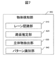
- FIG. 1 shows a block diagram of the in-vehicle environment recognition device.
- Cameras arranged in parallel to the left and right are used as stereo cameras to recognize the on-vehicle ambient environment.
- the stereo camera unit 100 uses left and right images captured by the left and right cameras. In order to perform stereo matching based on the right image, basically, the sensitivity, geometry, etc. should be matched to the right reference.
- the stereo camera unit performs pre-processing for matching in combination with imaging of the left and right cameras.
- the calibration corresponding point search unit 200 searches for characteristic points of the left and right images from the image, searches for corresponding left and right corresponding points on the left and right images from among the feature points, and aligns the left and right images.
- the error management unit 300 manages the errors of the left and right cameras.
- the result of the calibration corresponding point search unit 200 is one piece of information for error estimation, and the measurement result of a thermometer installed inside the camera, the shutter time of the stereo camera unit 100, and the like.
- exposure information such as gain, travel road estimation results such as lane and road surface estimation results, light source environment estimation results, weather estimation results, etc .
- noise factors that affect stereo matching are managed, and here, information for deciding what stereo matching method should be performed are managed.
- the matching unit selects an appropriate teleo matching method.
- the parallax accuracy and the parallax density generally decrease.
- a reduction in parallax density can be suppressed, and higher-precision, high-density three-dimensional shape recognition can be performed.
- the running calibration unit 500 grasps geometrical errors of the left and right cameras which change in time series while accumulating the results of the calibration corresponding point search unit 200 in time series. By performing long-term monitoring, the relative geometric error etc. of the left and right cameras gradually generated are corrected accurately and stably. The implementation of the correction is also fed back to the error management unit 300 and the like.
- the object detection unit 600 also uses a road surface estimation unit which is also used to find the foot position of lane recognition and solid object detection used for lane departure warning, and three-dimensional information obtained by stereo matching from stereo cameras of left and right cameras. A certain parallax image is used to perform three-dimensional object extraction, and it is detected whether this three-dimensional object is a car, a person or a bicycle. Based on these detection results, the alarm control unit 700 implements an alarm for preventive safety and vehicle control. Also, if the geometric or sensitivity error is too large for stereo matching with the left and right camera states, giving up on sensing is performed.
- the stereo camera unit 100 performs preprocessing for performing three-dimensional restoration using images captured by a plurality of cameras.
- the relative positional relationship between the two cameras is known from the previous stage using at least three-dimensional reconstruction, and it is known that the rough sensitivity and geometric calibration have been made even if the accuracy is low before product shipment. It assumes.
- the sensitivity calibration referred to here is to improve the matching accuracy between the two cameras which are the same image quality of the images seen by the two cameras together.
- the luminance of the two cameras is equal to the luminance.
- the adjustment of the offset and gain of the image sensor, the check of whether there is a defect in the image pickup device, the correction of the lens light collection characteristic which becomes darker as it goes to the lens periphery, etc. are raised.
- a correction value is provided, and after shooting with a camera in the imaging unit 110, the sensitivity correction unit 130 performs correction so that the sensitivities of a plurality of cameras become similar.
- the exposure adjustment unit 120 determines a base camera as a reference of a plurality of cameras, and matches the exposure conditions (shutter speed and gain) of other cameras in accordance with the exposure conditions of the base camera. As a result, by aligning exposure conditions in imaging among a plurality of cameras in advance, there is an effect that the luminances on the images of the same subject become equal, whereby the same object captured among a plurality of cameras is obtained. It will be preprocessed so that the features on the image of are similar.
- FIG. 9 shows a method of exposure adjustment. As shown in FIG. 9, in consideration of an object to be recognized, an exposure adjustment processing area for analyzing the luminance distribution is provided in an area where a road surface, a white line, and a preceding vehicle are included.
- the dotted line area on the image in FIG. 9 indicates a processing area for exposure adjustment. Analyze the luminance distribution in the multiple processing areas, weight the areas, combine the luminance distribution, and make the exposure condition brighter when dark based on the average luminance, and darken when bright Change to conditions.
- the lower part of FIG. 9 shows a method of changing the current exposure condition. On the horizontal axis, the current exposure value is adjusted to move to the left when the surrounding light source environment is bright, and to the left when it is dark. This change indicates that if the current shutter speed has not reached the upper limit value, light and dark adjustment is performed only with the shutter, and conversely, the shutter speed remains constant after the shutter reaches the upper limit value. Adjust the brightness at the height of the
- the gain that leads to image quality deterioration is basically a diagram showing that the shutter time is adjusted so as not to be used as much as possible, and after the shutter can not be set for a long time, it is adjusted with the gain.
- the shutter speed and gain information are also input to the error management unit 300.
- the luminance of the camera is expanded and used for matching. Is known in advance. It also serves as a source of information to inform the error management unit what these exposure conditions were.
- the exposure adjustment and the sensitivity correction are performed by using an on-vehicle stereo camera arranged between a plurality of cameras, in particular, in the present embodiment, right and left. However, the sensitivity correction between the left and right cameras is simply implemented in advance.
- the left image similarly, as shown in FIG. 9, a rectangular area set so that substantially the same road surface is set is set, weight is added to each area similarly to the right image, and luminance distribution is synthesized.
- the sensitivity deviation between the left and right is analyzed by obtaining the average luminance.
- the analysis result of a single frame is used by the light source environment estimation unit 340, and when performing correction, the simple sensitivity correction unit 380 performs sensitivity correction based on the analysis data.
- the sensitivity calibration unit 530 of the calibration unit 500 during traveling observes and manages sensitivity deviations during traveling in time series, so that the sensitivity deviations on the left and right occur in the long run, and should it be corrected with high reliability? Etc., and the final execution determination is performed by the execution management unit 540.
- the geometric correction table generation unit 140 generates a correction table for performing the lens distortion correction and the relative position correction so that the images of the two cameras are parallelized.
- a calibration chart in which circles are arranged at equal intervals or a grid pattern for calibration on a camera is taken, and lens distortion correction of a single camera is performed.
- the left and right cameras are parallelized.
- the relative positions of the left and right cameras are estimated by showing the same calibration chart, and based on this, the images of the left and right cameras are finely parallelized
- a table in which the lens distortion correction table and the parallelization table are combined is generated by the geometric correction table generation unit 140, and in practice, the stereo image generation unit 150 generates a frame-corrected image for each frame. .
- the light source environment estimation unit Whether data should be collected and corrected should be analyzed to analyze the data, and the simple sensitivity correction unit 380 performs correction.
- sensitivity calibration unit 530 determines whether sensitivity calibration should be performed. Implementation. The execution is performed in the execution management unit 530, and the reflection on the actual image is performed by changing the correction amount in the sensitivity correction unit 130, thereby performing the sensitivity correction on the image before stereo matching.
- the error amount of sensitivity there are also several methods for estimating the error amount of sensitivity, the first of which is the change in noise amount and sensitivity characteristics due to temperature.
- the sensitivity characteristics of the left and right are measured at a predetermined range of temperature at the time of factory calibration in advance and adjustments are made so that the left and right sensitivities become the same, these change on the CMOS when the temperature of the imaging device changes. It also affects the amount of noise and the luminance distribution of the image to be captured. In addition, since these have reproducibility depending on temperature, correction is performed so as to equalize the luminance offset and gain such that the sensitivity characteristics of the left and right cameras match.
- the calibration unit 500 can determine whether the correction should be made or not while the traveling calibration unit 500 is able to determine the reliability and whether the change should be made continuously, and the sensitivity calibration unit 530
- the correction value may be determined by using a correction coefficient based on a temperature difference to match the image quality at the time of factory calibration or to determine a correction value to align the relative luminance offset and gain in Reflection on an actual image is performed by the sensitivity correction unit 130 using the correction value.
- the correction amount increases and the error amount of the estimation error increases as the time of calibration in the factory increases, so the temperature at the time of calibration in the factory is near the center of the operating range and Calibration is performed in a state where the temperature is adjusted so as to fall within the range, so that it is possible to easily cope with the change of the sensitivity characteristic due to the temperature change during traveling.
- sensitivity correction may be performed according to the result of the current exposure adjustment.
- the normal exposure adjustment itself determines the correction values of the shutter and the gain as the exposure condition by analyzing the luminance distribution based on the image of the master right camera.
- the calibration unit compares the brightness distribution of the left and right cameras while traveling, and verifies whether the correction should be made while comparing the difference in the temperature of the left and right cameras. Do.
- the calibration corresponding point search unit 200 extracts the left and right corresponding points as basic data for grasping the relative position shift between the left and right cameras, and is determined to perform three-dimensional restoration with the current stereo camera.
- the calibration unit during traveling when the calibration unit 500 estimates the error amount with respect to the relative position of the left and right cameras and the geometric error amount is larger than a certain threshold and is higher than the certain threshold.
- the geometric correction table implemented by the stereo camera unit 100 is changed based on the value of the geometric calibration calculated at 500. As a result, the parallax accuracy and the parallax density are increased by correcting the positional relationship parallel to the sensitivity so that the stereo matching of the left and right camera images can be easily performed and the same object looks the same as much as possible.
- the processing region determining unit 210 first determines the processing region. We want to acquire more data from more dispersed positions on the image so that the left and right correspondence points can be analyzed as much as possible and the geometry of the left and right cameras can be easily analyzed. However, extraction of corresponding points is a process with a high image processing load, and it is difficult to carry out from the entire screen of the left and right images.
- the processing area determination unit 210 disperses in advance on the image to make a predetermined rectangular area. Are set and image processing is performed only within this range.
- the dotted line area shown in FIG. 10 is a candidate for the processing area.
- narrowing-down is further performed from among the plurality of processing area candidates set.
- the processing area to be used is further narrowed down from among the plurality of processing areas set. There are 14 areas set in advance, and the processing area is selected from the above edge number and strength. If the number is more than 6, 6 processing areas to be scattered on the screen are further selected.
- this processing itself may determine the processing area based on one of the left and right images. Since the determined processing area is set so that the right and left become a pair, the right is determined and the corresponding area on the left is also used for feature point extraction. It is important for calibration accuracy to utilize left and right corresponding point information evenly from the entire screen by utilizing time series data, but this is mainly performed by the calibration unit 500 during traveling.
- the left and right feature point extraction unit 220 extracts feature points before taking corresponding points in the processing area selected by the processing area determination unit 210 described above. Since this feature point is desirably a point having a unique feature on the image, a point that is a corner due to a change in texture having a brightness change in each of the vertical and horizontal directions is extracted. As indicated by the dotted circle in FIG. 11, the feature points are extracted from the pattern on the image not only in the linear luminance change but also in the corner having the luminance change in the orthogonal direction.
- the corresponding point extraction unit 230 describes the feature quantities at each feature point, and determines whether the feature quantities are similar. For example, as shown in FIG. 12, this feature quantity is binarized by comparing the brightness difference between the center position and the surrounding position and the brightness difference between the surrounding positions, with the coordinates of the feature point as the center. Values stored as binary data strings are used as feature quantities. Such a feature quantity description method may use luminance differences as feature quantities without binarization. The feature amount is described from surrounding pixels centering on the feature point, and the corresponding point extraction unit 230 executes a search for left and right corresponding points using the similarity between the data.
- the simple noise removing unit 240 first recognizes that the false correspondence point is the false correspondence point because the correspondence point is not within the allowable range of the parallelization. judge. In particular, noise is identified as having a large deviation in the vertical direction of the image even in comparison with surrounding points.
- the error management unit 300 is a department that analyzes and manages errors occurring in the stereo camera according to factors.
- the amount of parallelization error and sensitivity error caused by temperature change is estimated.
- the influence of the deformation on the camera housing and the change in the sensitivity of the camera imaging device become larger.
- the amount of geometric error generation and the amount of sensitivity error generation are estimated according to the temperature indicated by the thermometer near the image pickup device at the time of use of the camera from the time of calibration. An example is shown in FIG.
- the table in FIG. 13 itself is the same, but even at temperatures other than at the time of normal calibration, 60 degrees-20 degrees
- the error at the time of temperature may be estimated by linear interpolation, and then extrapolation may be performed to estimate the occurrence of each individual error.
- the amount of error generated is estimated based on the table of FIG.
- this can be used only when the same individual has repeatability in which similar errors occur at the same temperature.
- the time management unit 320 is used to estimate the influence of deterioration over time by managing the total elapsed time from calibration at a factory or the like at a dealer or the like and maintenance of parts from the factory. For items that are difficult to be corrected without traveling or special facilities, such as lens deterioration, discoloration, etc., this total elapsed time is used to estimate to what extent aging has progressed. An increase in noise due to temperature change is temporary and occurs independently of aging, so here we will show a method to manage geometrical and sensitivity errors due to aging without considering temperature change.
- time management is performed for each error.
- For the total elapsed time use the same time item and the same time shared by items marked with ⁇ .
- the camera has been changed for repair, the total elapsed time and the elapsed time after calibration are reset.
- the managed time may be reset even in the case of re-inspection.
- the item for estimating the amount of error based on the elapsed time after calibration is indicated by a circle in the column of elapsed time after calibration.
- This item is a calibration, and it is time to be reset if it is corrected. Therefore, if the calibration correction works at different timings for each item, it is different whether they are reset or not. For example, in the case where only the geometric vertical calibration is performed, the elapsed time after the other calibration is not reset, and the elapsed time is continuously counted, and only the geometric vertical calibration elapsed time is reset. The same applies to the other items, and if only the sensitivity offset is calibrated, the design is such that the elapsed time after calibration of the other items is not reset.
- the time management unit manages, for each item, an elapsed time after being corrected by the calibration while traveling, for items corrected by the calibration while traveling.
- the traveling path estimation unit 330 analyzes the unevenness on the road surface and analyzes the time-series data, so that the current traveling condition is a road with few unevenness or a road that is not paved. Or estimate the uneven road surface with holes and falling objects. It is possible to estimate the influence on the geometry by analyzing in advance the extent to which the geometrical conditions of the left and right cameras are affected according to the estimated uneven condition of the road surface.
- the calibration unit corrects only the correction value of the average of the vibration by the time series data without correcting the vibration component.
- the correction for the vibration is performed by the simple geometric correction unit 360 for the simple correction of only the frame using the information of the left and right corresponding points as the estimation result of the traveling path estimation unit 330. If the instantaneous left / right difference is unknown, calibration is not performed in a normal manner, but correction is performed in a running calibration unit 500 that utilizes time-series data, instead of performing correction every frame.
- the geometric correction table of the stereo camera unit 100 By editing the geometric correction table generation unit 140, the parallelism of the left and right cameras is maintained.
- the correction in the simple correction unit is simple, and there are corrections that can not be dealt with in the simple correction, such as correction in the rotation direction and correction in the enlargement / reduction direction. For this reason, even if simple correction is performed in advance, data on how much parallelization error is likely to occur depending on the travel path is acquired, and based on the data, assumed values of geometric errors likely to occur from the current travel path I will assume.
- the traveling path ahead of the host vehicle is estimated from the vehicle speed and the steering angle, and the road surface of the host vehicle traveling path is relative to the vehicle body from the parallax information of the area where the host vehicle travels.
- the position and orientation are measured in time series, and it is determined whether the camera is affected by the situation where the vehicle is pitching at all times.
- the change in relative position and attitude is small, and parallax can also be detected stably.
- the camera housing is inexpensive and the camera housing is also deformed due to pitching, the influence of the reduction in parallax may be considered.
- the simple geometric correction unit 360 performs only simple geometric correction, and is used when performing geometric correction of only this frame or only a fixed frame interval, and does not change the geometric correction table itself. Therefore, vertical and horizontal corrections are basically performed, and corrections such as complicated lens distortion are not performed. Of course, since the lens distortion is not instantaneously deformed due to the instantaneous geometric deviation, the simple geometric correction unit 360 is used as a correction unit that suppresses an error generated due to the instantaneous vibration.
- the correction amount in the simple geometry correction unit 360 which is instantaneously corrected is calculated. Subtract to estimate the maximum amount of error that may occur in the current frame.
- the amount of error to be estimated may be managed according to geometric type, vertical, horizontal, scaling, and rotation, as in the error increase / decrease table in the case of temperature change shown in FIG. It may be integrated into only vertical and horizontal positional deviations. Further, if the width of the vertical search of the matching method is taken into consideration, an estimated value of only the maximum amount of deviation in the vertical direction may be used.
- the temperature management unit 310 measures in advance the amount of error generated for each temperature, and estimates the amount of sensitivity error as shown in FIG. 14 based on the actual temperature when using a stereo camera. Furthermore, the time management unit 320 predicts the deterioration of the lens based on the total elapsed time, and measures the elapsed time after calibration while traveling for each noise type and manages the time. Thereby, the amount of change in sensitivity based on the elapsed time is estimated.
- the light source environment estimation unit 340 estimates the noise condition on the image according to the camera shutter speed and gain set by the exposure adjustment unit 120, the average luminance by region on the image, and the like. Basically, the longer the shutter time, the less the noise. However, even when the shutter is long, the dark part of the image is likely to be noisy, and the average luminance of each region is also used to determine the amount of noise on the image. presume.
- the characteristics of the camera are checked in advance, the amount of noise increase according to the shutter and gain is checked according to the type, and while the camera is in use, the adaptive exposure conditions (shutter speed, gain) The amount of noise is checked according to the average brightness of the surroundings, and the amount of noise based on this is estimated by the light source environment estimation unit 340 according to type.
- the weather estimation unit 350 predicts the weather condition from the operation condition of the wiper, the outside air temperature, the cloudy condition of the glass by other sensors, and the raindrop adhesion judgment result by the raindrop sensor etc. Make a judgment. Based on the result of the weather estimation unit 350, it is determined that there is a possibility that a lateral difference may occur in the offset, gain, blur, etc. of the sensitivity generated at the time of camera imaging. In this case, unlike the error estimation unit, it is difficult to estimate in which region the luminance offset, gain, and blur occur in which region even if it is raining. It is determined that the sex is high.
- the simplified sensitivity correction unit 380 performs simple correction of the luminance offset, gain, etc., targeting only the sensitivity error that has occurred mainly in a short period of time.
- long-term correction based on temperature changes and aging
- basic measures are implemented in calibration while driving, and it is simple only when sudden changes in the light source environment occur within several frames. It corresponds by sensitivity correction. If the exposure conditions are stably changed, it is assumed that the calibration while traveling is the case.
- the average luminance is monitored based on the right image for exposure adjustment, the difference between the left and right sensitivities is related by calculating the average luminance in the same manner for the left image as well, and this is used as the correction amount.
- the sensitivity noise estimation unit 390 subtracts the amount corrected by the simplified sensitivity correction unit 380 from the sum of the error amounts estimated by the temperature management unit 310, the time management unit 320, the light source environment estimation unit 340, and the weather estimation unit 350. It is estimated that the amount is the current sensitivity noise amount.
- the weather estimation unit 350 manages, as information, that there is a possibility of a sensitivity error.
- a simple method is used for instantaneously occurring errors, for example, in the case of geometry, if only the vertical or horizontal offset is the sensitivity A limited error suppression process such as only luminance offset or luminance gain is performed, and further, an error which can not be suppressed by the simple correction of the existing camera, an error which can not be coped with by calibration while traveling, etc. are managed.
- the matching unit 400 selects a matching method that can obtain more appropriate parallax information according to the estimation result of the geometric error and the sensitivity error estimated by the error management unit 300.
- the integrated management unit 410 manages the amount of error by classifying the geometric error and the sensitivity error in the current frame obtained from the error management unit 300 respectively.
- this total amount may be managed, but in the case of an index that indicates the possibility that an error has occurred as a result of the weather detection unit, Based on the magnitude of the possibility, a predetermined error amount is added in advance to manage the error amount.
- the whole image is not defined as Apixel vertical displacement, and the worst value is defined as Apixel.
- the error at the position of the largest deviation at the screen edge or corner is defined as C pixel.
- the same definition method is used for horizontal and scaling.
- the difference in sensitivity between the left and right cameras is also defined by type.
- five types of sensitivity noise amounts that are representative and have matching effects are estimated and managed.
- the types of sensitivity noise are point noise, line noise, blur, offset, and gain.
- Each point noise is a point-like noise that is on the image, and in spite of capturing an object of the same luminance. This is a phenomenon that makes the brightness different from that of the surrounding pixels, and such noise increases when shooting with increased gain in extremely dark conditions, at extremely high temperatures, at low temperatures, etc.
- the error management unit 300 carries out estimation by understanding camera characteristics.
- the point-like noise amount is estimated mainly by the error estimation based on the result of the temperature management unit 310 and the error estimation based on the exposure information of the light source environment estimation unit 340.
- line noise is noise that enters vertically on the image, and is a noise factor that makes the luminance different from the pixels on the adjacent line by the vertical line even when imaging the plane of the same luminance.
- the temperature management unit 310 of the error management unit 300 calculates the position and the intensity in consideration of different amounts which are known to occur at extreme temperature characteristics and different for each camera.
- blur numerically expresses the sharpness of an image such as lens defocusing as a characteristic of the resolution of the image.
- the error management unit 310 estimates the amount of error from temperature change, aging deterioration, and further, from adhesion of water droplets due to the weather. Like the other noises, the temperature management unit holds the blur value at the time of temperature change in the table of FIG. 13, and based on this table, the degree of blur according to the temperature is estimated. Similarly, with regard to aged deterioration, based on the total elapsed time, the amount of decrease in lens resolution to be generated is held as data in the form of a table, and the current amount of decrease in resolution is estimated based on this.
- the analysis result at the time of actual water drop adhesion is held in a table beforehand, and when it is judged that there is a possibility of this water drop adhesion, it is blurred by the amount held in the table Judge that there is a possibility.
- These estimators are used to estimate a blur value that indicates the resolution of the lens in the current frame.
- the luminance offset and the luminance gain are separately estimated from the ambient light source environment including the aging deterioration, the temperature change, and the exposure adjustment result. These are also basically the same, and the temperature characteristics are estimated based on the error amount according to temperature shown in FIG. 13, and with regard to aging deterioration etc., the previous table is similarly held as data. Estimate the error amount based on the current temperature and the total elapsed time. Conversely, for instantaneous errors, estimates of sensitivity offset and sensitivity gain are used based on the results of the sensitivity noise estimator of the error manager.
- the traveling path estimation unit and the light source environment estimation unit based on the results of the traveling path estimation unit and the light source environment estimation unit, it is assumed that a scene is currently traveling, and geometric noise and sensitivity noise are also detected for a specific scene in order to select an excellent matching method in that scene.
- the weight of a scene estimated to be probably running is represented by a weight of 0 to 10, and 10 indicates a weight that strongly influences the selection of a matching method.
- the characteristics of the camera are investigated, and this stereo camera tends to generate large geometric noise in advance, and whether the geometric error greatly affects the parallax image obtained by stereo matching, the sensitivity noise is large. It is easy to occur, and it is investigated in advance whether sensitivity errors have a large effect on parallax images obtained by stereo matching to balance the importance of geometry and sensitivity, and each error type also depends on the occurrence frequency and error amount Determine the importance.
- sensitivity errors have a large effect on parallax images obtained by stereo matching to balance the importance of geometry and sensitivity, and each error type also depends on the occurrence frequency and error amount Determine the importance.
- More adaptive adjustments may be made by changing this importance in real time, adjustment that places importance on the evaluation result for sensitivity noise, and adjustment that places importance on the evaluation result for geometric noise More adaptive adjustments may be made by
- the integrated management unit 410 aggregates information on the geometric noise amount and the sensitivity noise amount for each detailed type, and the sensitivity noise, the geometric noise, and the importance for each type of the specific scene.
- the score for each noise is calculated and filled in the horizontal direction.
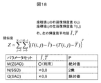
- the performance score of the matching method is generated with respect to geometry: lateral noise: Bpixel, geometry: rotation: C: pixel, geometry: scaling: D: pixel. Since the score indicating the matching performance differs according to the error estimator, calculation is required each time the estimation error results change.
- sensitivity noise a cell is filled with a score indicating matching performance when the point noise intensity of the sensitivity noise becomes E times that at normal time.
- the scores are summed side by side in rows to obtain final scores, and it is determined that the highest scoring method is the most appropriate for the current matching method.
- a matching method including pre-processing and post-processing shown in one horizontal line will be described.
- the matching method is divided into pre-processing, matching main processing, and post-processing, and further management including the detailed ON and OFF.
- the integrated management unit excludes the noise removal filter and the invalid parallax determination, which are always determined to be ten processes, out of the management target of the integrated management unit in FIG. 15, but the noise is removed when actual stereo matching is performed.
- the filter unit 442 and the invalid parallax determination unit 443 are to be implemented.
- the first method from the top of the table in FIG. 15 in the series of matching methods including pre-processing and post-processing is with contrast correction, with noise removal, with stereo matching window size 16 ⁇ 16, without thinning, with matching method Z, parameter M , Complement of parallax, is a method.
- this series of matching methods cells are filled with evaluation points when the geometric error is Apix in the vertical direction due to geometric noise. It is then possible to perform the process of (2), and then to fill the cells in order, such as the lateral error, to calculate the evaluation point of this method for the estimation error.
- the basic method is a method that is strong at night, the gain at exposure conditions is high, or noise is strong and strong at low contrast when the camera temperature is high or low. It is a method that assumes a method.
- the first method that does not shake the search for stereo matching up and down efficiently if it is small, depending on the magnitude of the geometric error at that time, performs the search for stereo matching in the case of the second method.
- the third to fifth methods from the top are basically used when the noise of the sensitivity system is relatively low, and the vertical and horizontal noises of the geometrical error increase in the fourth,
- the fifth method is a method of searching for stereo matching in the vertical direction that can easily absorb geometric errors.
- the sixth to eighth methods using the stereo matching method of X are methods resistant to rotational errors, and also relatively robust with respect to sensitivity errors.
- This method is relatively strong when rotation errors, scaling, and other errors increase, and as the rotation error increases, the search range for stereo matching with numbers 7 and 8 increases in the vertical direction, making it a robust method.
- the methods of No. 9 and No. 10 shown at the end give a strong evaluation result in the bright but low contrast and noisy cases, and the final parallax complementation is carried out, resulting in a relatively robust experimental result.
- evaluation is performed for each error type as described above, and an optimal matching method is performed according to the estimation error occurring in the current frame. By selecting pre-processing and post-processing of the combination, it is possible to select a more appropriate parallax image.
- the pre-processing is processing for improving the performance of stereo matching on left and right images before stereo matching, and is performed by the matching pre-processing unit 420.
- Contrast correction is mainly provided for nighttime, noise removal for back light, and when noise increases at high temperature, low temperature, nighttime etc.
- the contrast correction unit 421 is a method for improving the recognition rate by correcting the contrast for white lines, signs, pedestrians, etc. that are mainly prepared for nighttime use and are difficult to see in dark and low contrast. It is a process for making it easier to extract three-dimensional objects such as dark and hard to see areas.
- a noise removing unit 422 mainly used to reduce a point noise system is prepared, and processing is performed to suppress the brightness of the pixel of interest based on the surrounding brightness information for the pixel that largely changes with the surrounding brightness.
- the matching main processing unit 430 performs the main matching processing in stereo matching, but performs the processing after determining various settings and the like before performing the matching processing.
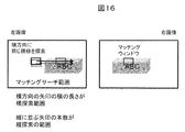
- the vertical and horizontal search ranges are set by the vertical and horizontal search range setting unit 431.
- the basics of matching are shown in FIG. 16, but the length of the arrow in the horizontal direction in the matching search range is the horizontal search range, and the number of arrows aligned vertically indicates the basic idea as the vertical search range .
- the description “search range ⁇ 1” described in the integrated management unit 410 means performing a horizontal search for a total of three arrows (pixels) by shifting the main horizontal search arrow up and down by 1 pixel.
- the matching method setting unit 432 performs operation preparation and the like of the matching method determined by the integrated management unit 410.
- the matching methods Z and X are calculated on a score basis for each method based on the estimated error amount, and the method is changed and used according to the total evaluation point.
- the equation of the matching method Z and the parameter set are shown in FIG.
- the matching method Z is a method of comparing luminance differences in the matching window. However, the equation slightly changes based on the parameter set.
- the parameter adjustment unit 435 performs parameter adjustment of stereo matching.
- the parameters differ depending on the matching method in the present embodiment, parameter changes of the matching method Z in which the parameters are mainly changed will be described using FIG.
- the parameter M after subtracting the luminance average value of the left and right images, the luminance difference is compared, and the comparison result is used as an absolute value, generally using a method called ZSAD.
- parameter N the average luminance value of left and right images is treated as 0 which is not used, and a method called SSD is generally used in which the square value of the luminance difference is used for luminance difference comparison.
- parameter Q the average luminance value of the left and right images is treated as 0 which is not used, and the absolute value of the luminance difference is generally used in the luminance difference comparison, which corresponds to a method called SAD.
- the matching method X is a method of handling only the parameter P of the default setting, and the method is shown in FIG.
- the luminance difference from the matching window center is expressed as 0, 1.
- this represents the luminance information in the window with all 0 and 1 bit strings. Since the corresponding matching windows in the left and right images are all represented by bit strings, the similarity between these bit strings is calculated by the Hamming distance. It is assumed that the bit strings represented by 0 and 1 are similar to each other if 1 bit each is 0 or 1 with each other, otherwise it is not added.
- This is a method of calculating the degree of similarity of bit strings and performing stereo matching. It is characterized in that the amount of data is considerably reduced, and the circuit scale can be considerably reduced, so it is a method that can be easily combined with other methods such as noise removal method, contrast correction, parallax interpolation and the like.
- the matching window size unit 433 determines the window size of the matching around the pixel of interest in order to specify the pixel to be used in stereo matching. Referring to FIG. 16, in the present embodiment, either 8 ⁇ 16 pixels or 16 ⁇ 16 pixels is selected as the size of the base from the result of the integrated management unit 410 in the present embodiment.
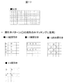
- the thinning unit 434 performs thinning in accordance with the result determined by the integrated management unit 410 here. As shown in FIG. 17, thinning out of pixels used for matching in the matching window size is performed. Even in the case of halving pixels, as shown in FIG.
- the matching processing unit 436 executes the matching processing with the contents set in the vertical and horizontal search range setting unit 431, the matching method setting unit 432, the matching window size unit 433, the thinning unit 434, and the parameter adjustment unit 435 so far. Save
- the matching post-processing unit 440 performs post-processing on the parallax image generated by the matching processing unit 436.
- the integrated management unit determines the execution availability in order to change the availability of the execution in real time.
- the parallax interpolation process is a process of changing the value of the parallax of interest from the parallax value of the surrounding when the parallax value of the parallax of interest is significantly different from that of the parallax of interest.
- a denoising filter is a filter that determines whether the similarity of matching is reliable or not, and there is a high degree of similarity similar to parts other than the highest degree of matching result similarity within the search range From this point of view, it is judged whether the current degree of similarity is noise based on whether it can be said to be similar as compared with the other parts of the image.
- the invalid disparity determination unit 443 is also most similar by checking whether the degree of similarity is not too low, but whether the degree of similarity is too low to be reliable compared to the normal degree of matching Based on the above, it is determined that the parallax is high if the similarity is high, and low if the similarity is low.
- the on-the-fly calibration unit 500 performs on-the-go calibration.
- the factory usually calibrates, but due to various factors such as insufficient accuracy in the first place, age-related deterioration, deformation caused by temperature change generated while traveling, sensitivity change, and geometrical error of left and right cameras due to vibration. The integrity of the left and right cameras may be lost.
- the traveling calibration unit 500 performs correction by calibration during traveling in order to suppress the error generated during traveling as described above.
- the time-series data management unit 510 manages data as a basis of calibration.
- the amount of deformation is stored separately for each temperature because the geometric distortion of the left and right cameras that deform due to temperature change has a certain regularity.
- temperature information that changes in time series is acquired from the temperature management unit 310, and is managed as time series data here.
- the corresponding points of the left and right cameras are acquired from the corresponding point searching unit 200 for calibration.
- accuracy is improved by using time-series corresponding point information to confirm that it is truly deformed or by using information from the entire screen.
- the geometric calibration unit 520 performs calibration aimed at
- the sensitivity calibration unit 530 carries out sensitivity correction based on the fact that the temperature change of the left and right cameras is equal to or greater than a certain amount using the temperature information and that this is continuous to a certain extent.
- neither geometric calibration nor sensitivity calibration has errors due to temperature characteristics, and the temperature of the thermometer does not completely measure the temperature of the deformed portion or the image sensor, but it is near An error occurs because the temperature of the For this reason, while performing simple correction by running calibration, sensitivity errors as well as geometrical errors are only reduced errors, and if the temperature is different from the temperature at the time of factory calibration, there is a large error. Further error suppression is implemented by changing the method.
- sensitivity calibration is also compatible with yellowing due to aging, etc., but since it progresses only gradually and considerable errors occur depending on each camera, the time of this aging and Furthermore, the correction by sensitivity calibration is performed when the sensitivity error of the error management unit 370 always occurs. Since there are various types of errors that occur in the left and right cameras in this way, there are two types of errors that can be absorbed during calibration while suppressing errors by calibration while traveling, and then matching absorption of remaining error factors Implement measures. As a result, usually, when an error occurs in the left and right cameras, loss of parallax information and deterioration of parallax accuracy occur, but high-resolution parallax information with high density and accuracy can be obtained by suppressing this as much as possible.
- the execution management unit 540 performs calibration after confirming that the result of the geometry calibration unit 520 does not change significantly with the conventional value and is within a normal and possible range, etc.
- the correction of the geometric correction table generation unit 140 is performed.
- calibration is executed after confirming that the value is not extremely different from the conventional value and is within the normal and possible range, and the like, and the sensitivity correction unit 130 of the stereo camera unit 100 is performed. Rewrite the correction value of.
- the information is used to manage the remaining error.
- the object detection unit 600 performs lane recognition, road surface estimation, three-dimensional object extraction, and identification of a pedestrian and a vehicle by pattern identification based on the parallax image generated by the matching unit.
- the lane recognition unit 610 detects a white line on the traveling road of the vehicle using the luminance image and the parallax image of the right camera, which are input. By detecting the left and right white lines on the image, the infinite distance intersection point of the left and right lane marks is obtained. By implementing this for both the left and right cameras, it is possible to use for correction of geometrical deviation of the left and right cameras as well as improvement of recognition reliability.
- the simple geometric correction unit 360 and the geometric calibration unit 520 may utilize these pieces of information for geometric correction of the left and right cameras.
- the road surface estimation unit 620 uses the parallax information to analyze the parallax on the road on which the vehicle is traveling to estimate the inclination and height of the road on which the vehicle is traveling. Based on the road surface estimation result, extraction of the three-dimensional object present above the road surface is performed by the three-dimensional object extraction unit 630.
- the pattern recognition unit 640 performs pattern matching on the three-dimensional object extracted by the three-dimensional object extraction unit 630 at the pattern identification unit 640 whether the three-dimensional object is a pedestrian or a vehicle.
- the vehicles identified by pattern matching can identify the positions on the left and right camera images, so they look at the same object in the left and right image areas, so if the sensitivity correction is complete, the luminance distribution in that area is completely It should be the same.
- the sensitivity correction of the left and right cameras may be performed by the simple sensitivity correction unit 380 or the sensitivity calibration unit 530 using such information.
- the control unit 700 executes warning and control to improve safety and convenience according to the result of the lane, the pedestrian, the vehicle, and other arbitrary three-dimensional objects implemented by the object detection unit 600.
- the result of lane recognition it is freely selectable as to whether the user carries out the control, the alarm, or the non-operation state, so switching between alarming and control is performed based on the user's setting.
- the alarm unit 710 sounds an alarm if it is likely to deviate from the lane based on the lane recognition result and the inference result of the vehicle behavior.
- the control unit 720 performs lateral control to return the vehicle so as not to be out of the lane.
- the give-up unit 730 gives up the entire system when the geometrical error or the sensitivity error of the left and right cameras exceeds the allowable range based on the result of the error management unit 300. On the other hand, if it can be determined that, for example, the camera which has been hot has cooled and returned to the normal temperature stably, release of give-up and the like are also performed.
- S02 Analyzes focusing on the right image and performs exposure adjustment of shutter speed and gain.
- S05 Perform left and right corresponding point extraction from left and right images. Used to measure left and right geometric errors. It can be used for instantaneous correction, but it will be used in the simple geometric correction S09, in which errors remain after simple correction. For long-term correction, it is used in running geometry calibration S16 from corresponding points in time series which are accurate but can not cope with instantaneous geometric distortion.
- S12 Predict the weather, and estimate if blurs or the like will occur due to water droplets adhering to the windshield during rainy weather.
- the sensitivity error amount is estimated by subtracting the simple correction amount from the estimated sensitivity noise total.
- S19 Calculate the score by calculating the score of each cell of the table showing the most appropriate matching method for estimated values of geometric error and sensitivity error, and calculating the score. Choose the best method.
- S20 Perform stereo matching using the selected stereo matching method.
- an error may be measured in the required three-dimensional shape due to the bias of the texture in the matching window, while analyzing the three-dimensional shape by stereo matching. . Therefore, by analyzing the texture in the matching window, the matching window in which an error occurs can be identified, and in order to suppress the influence due to this error, the measurement shop may be deleted or the detail measurement or the measurement may be performed again Point correction is performed, and alarm, speed control, and suspension control are performed based on the measurement results.
- the on-vehicle surrounding environment recognition device of this embodiment can be expressed as follows.
- An in-vehicle surrounding environment recognition device having an imaging unit, wherein an error management unit estimates an error of the imaging unit when obtaining a three-dimensional shape based on a viewpoint of the imaging unit, and an estimation result of the error management unit. It has a matching part which chooses a matching method.
- the error management unit manages the type and amount of error.
- the type of the error includes a geometric error
- the geometric error includes any one of vertical position, horizontal position, rotation, enlargement and reduction.
- the type of error includes an error of sensitivity
- the error of sensitivity includes any one of point noise, line noise, blur, sensitivity offset, and sensitivity gain.
- image portions are respectively provided on the left and right, and the geometrical error is corrected by the corresponding left or right points or the corresponding line information, and the amount of error remaining in the correction is estimated by the error management unit. Perform stereo matching process including direction.
- image parts are respectively provided on the left and right, the geometrical error is estimated from the corresponding left and right points captured by the left and right imaging parts, and generation of distortion or vibration over time is specified.
- the long-term error amount is classified into a long-term error amount, and the long-term error amount is corrected by using the left / right corresponding point data to correct the error by calibration so that the remaining error is reduced.
- the short-term error and the residual error are performed by selecting the stereo matching process suitable for the geometric error from correction of the geometric error in the vertical direction and the horizontal direction and a plurality of stereo matching processes.
- a temperature change of the imaging device is predicted based on a temperature sensor built in the imaging unit, and the error management unit estimates the error based on the temperature predicted by the temperature sensor.
- a road surface condition estimation unit for estimating the unevenness condition of the traveling road surface is provided, and the geometrical error is estimated.
- an error of the sensitivity is predicted based on exposure information of the imaging unit.
- the matching method changes at least one of contrast correction, noise removal, matching window size, thinning within the matching window, search range, matching method, parameter, and parallax interpolation.
- the in-vehicle environment recognition device of the present embodiment when restoring a three-dimensional shape using a plurality of cameras installed in a vehicle, relative geometric error between the plurality of cameras and the sensitivity that change with time, and sensitivity, it is possible to restore the three-dimensional shape with higher accuracy and high density. , It is possible to improve the recognition rate of the object recognized based on it.
Landscapes
- Engineering & Computer Science (AREA)
- Physics & Mathematics (AREA)
- General Physics & Mathematics (AREA)
- Theoretical Computer Science (AREA)
- Multimedia (AREA)
- Computer Vision & Pattern Recognition (AREA)
- Remote Sensing (AREA)
- Radar, Positioning & Navigation (AREA)
- Electromagnetism (AREA)
- Image Analysis (AREA)
- Measurement Of Optical Distance (AREA)
- Length Measuring Devices By Optical Means (AREA)
- Traffic Control Systems (AREA)
Abstract
本発明は、高精度で高密度な3次元形状の復元と、それを基にして認識される物体の認識率を向上させることを可能とする。発明は、撮像部110を有する車載周囲環境認識装置であって、撮像部110の視点に基づき3次元形状を得る際に撮像部110の誤差を推定する誤差管理部300と、誤差管理部300の推定結果に応じてマッチング手法を選定するマッチング部400と、を有する。
Description
本発明は、車載周囲環境認識装置に関する。
本発明は、車両に設置された2つのカメラにより車両周囲環境を認識する車載カメラに関する。予防安全技術の製品化が普及期に入りつつあり、車載カメラ、ミリ波レーダ、レーザレーダなどのセンシング技術も廉価に作る技術も重要となってきている。本発明は、カメラ(撮像部)を利用して車両周囲環境を認識するセンシング技術に関するものであり、特に2視点のカメラ情報を活用して3次元障害物を認識するアルゴリズムにおいて、その2視点の位置ずれを補正もしくは補完、許容する方法に関する。
走行中のステレオカメラの左右カメラの位置ずれを補正する、車載ステレオカメラの校正装置及び校正方法、特開2014-74632号公報(特許文献1)がある。
車両に設置されたカメラを活用して障害物3次元形状を推定する。この際に、複数台のカメラ位置がどのような位置関係にあるかということがあらかじめ既知であると、3次元形状を復元する際の処理が非常に容易であると同時に高精度に3次元形状を復元することが可能である。しかしながら、廉価な部品の利用による温度変化による形状変化、画質のばらつき、製造ばらつきなどがカメラ単体での誤差が想定されるだけでなく、適当に車体にカメラが取り付けられているような場合には、車体とカメラの相対位置のずれが生じ、振動やたわみなどが発生する。
高精度な部品と精密な組立を行うことで初期誤差が少なく、なおかつ使用中に幾何的にも感度的にも誤差の少ないカメラを製造することも可能であるが、どうしてもコストが高くなりやすい。また、走行中にある程度長い時間をかけながら徐々に発生する誤差に関しては、特許文献1に示すように左右対応点を用いることで、2つのカメラに生じる相対誤差を補正することが記されている。しかしながら、より短期間、単フレームでの幾何誤差発生や、補正後に残った誤差に関する対応方法、また感度誤差に対する対応方法は記されておらず、そのまま3次元復元すれば、密な3次元形状を得られない、低精度であるなど、さまざまな課題が生じる。
上記課題を解決するために、本発明は、撮像部を有する車載周囲環境認識装置であって、前記撮像部の視点に基づき3次元形状を得る際に前記撮像部の誤差を推定する誤差管理部と、該誤差管理部の推定結果に応じてマッチング手法を選定するマッチング部と、を有する。
本発明の車載周囲環境認識装置によれば、高精度で高密度な3次元形状の復元と、それを基にして認識される物体の認識率を向上させることを可能とする。
本発明の車載周囲環境認識装置は、より安全かつ快適に車両を制御するに、カメラを利用して自車両の周囲環境をセンシングし、自車両の制御や警報に必要な情報を出力することを特徴とする。
特に、ステレオカメラで三次元形状を解析する際に、テクスチャの偏りによって生じる誤差がある。ステレオカメラの基本原理に基づく影響であり、ステレオマッチングはマッチングウィンドウ内のテクスチャの特徴に基づいてマッチングを行っている。このため、マッチングの際に、マッチングウィンドウ内にほぼ均一輝度の特徴がない少ない領域と、輝度差が大きく特徴の多い領域が存在するような場合には、マッチングウィンドウを設定しているものの、特徴の多い領域がマッチングするような、3次元計測結果となる。このためマッチングウィンドウの中心の3次元結果を算出しているつもりが、テクスチャの多い領域に合わせたマッチングとなり、計測した3次元結果に誤差が生じる。
以下、実施例について図面を用いて説明する。
以下、実施例について図面を用いて説明する。
<図1 車載環境認識装置>
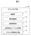
図1に車載環境認識装置の構成図を示す。左右に平行に並べられたカメラを、ステレオカメラとして利用し、車載周囲環境を認識する。ステレオカメラ部100では、左右のカメラから撮像された左右の画像を利用する。右画像をベースとしてステレオマッチングを実施するために、基本的には右基準に感度、幾何などを合わせるものとする。ステレオカメラ部では、左右カメラの撮像と合わせてマッチングのための前処理を実施する。キャリブレーション用対応点探索部200では、左右画像の特徴点を画像上から探索し、この特徴点の中から、左右画像上で対応のとれた左右対応点を探索して、左右画像の位置あわせが正しい状態が保たれているかどうかのチェックと共に、どの程度ずれているかということを推定する際に利用する。誤差管理部300では、左右カメラの誤差について管理する。上記、キャリブレーション用対応点探索部200の結果は、誤差推定のための1つの情報であり、この他にもカメラ内部に設置された温度計の計測結果や、ステレオカメラ部100のシャッター時間やゲインなどの露光情報、レーンや路面の推定結果などの走行路推定結果、光源環境推定結果、天候推測結果、などの情報から左右カメラに生じる感度誤差、幾何誤差のノイズ要因を推定し、管理する。ステレオマッチングに影響を及ぼすノイズ要因を、ここで管理、ステレオマッチング手法をどうすべきかの判断材料をここで管理する。上記の誤差管理部300の結果を基に、マッチング部では、適切なテレオマッチング手法を選定する。ステレオマッチングの前処理、メイン処理、後処理とそれぞれにおいて状況に応じた適切な手法を選定することで、通常では視差精度が低下する、もしくは視差密度が減少するような状況においても、視差精度と視差密度の低下を抑制し、より高精度、高密度な3次元形状の認識を可能とする。
図1に車載環境認識装置の構成図を示す。左右に平行に並べられたカメラを、ステレオカメラとして利用し、車載周囲環境を認識する。ステレオカメラ部100では、左右のカメラから撮像された左右の画像を利用する。右画像をベースとしてステレオマッチングを実施するために、基本的には右基準に感度、幾何などを合わせるものとする。ステレオカメラ部では、左右カメラの撮像と合わせてマッチングのための前処理を実施する。キャリブレーション用対応点探索部200では、左右画像の特徴点を画像上から探索し、この特徴点の中から、左右画像上で対応のとれた左右対応点を探索して、左右画像の位置あわせが正しい状態が保たれているかどうかのチェックと共に、どの程度ずれているかということを推定する際に利用する。誤差管理部300では、左右カメラの誤差について管理する。上記、キャリブレーション用対応点探索部200の結果は、誤差推定のための1つの情報であり、この他にもカメラ内部に設置された温度計の計測結果や、ステレオカメラ部100のシャッター時間やゲインなどの露光情報、レーンや路面の推定結果などの走行路推定結果、光源環境推定結果、天候推測結果、などの情報から左右カメラに生じる感度誤差、幾何誤差のノイズ要因を推定し、管理する。ステレオマッチングに影響を及ぼすノイズ要因を、ここで管理、ステレオマッチング手法をどうすべきかの判断材料をここで管理する。上記の誤差管理部300の結果を基に、マッチング部では、適切なテレオマッチング手法を選定する。ステレオマッチングの前処理、メイン処理、後処理とそれぞれにおいて状況に応じた適切な手法を選定することで、通常では視差精度が低下する、もしくは視差密度が減少するような状況においても、視差精度と視差密度の低下を抑制し、より高精度、高密度な3次元形状の認識を可能とする。
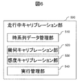
走行中キャリブレーション部500では、キャリブレーション用対応点探索部200の結果を時系列に蓄積しながら、時系列に変化する左右カメラの幾何誤差の把握を実施する。長期間監視することで徐々に発生した左右カメラの相対幾何誤差などを精度良く安定的に補正を実施する。補正の実施などは誤差管理部300などにもフィードバックされる。
物体検知部600では、車線逸脱警報に利用するレーン認識や立体物検知の足元位置を見つけるためにも利用する路面推定部、更に、左右カメラのステレオカメラからステレオマッチングにより得られた3次元情報である視差画像を利用して立体物抽出を実施し、この立体物が車なのか、人なのか自転車なのかを検知する。これらの検知結果に基づいて、警報制御部700では、予防安全のための警報や、車両制御を実施する。また、あまりに左右カメラの状態がステレオマッチングするには幾何もしくは感度誤差が大きいような場合には、センシングすることをギブアップする。
<図2 ステレオカメラ部100>
ステレオカメラ部100では、複数台のカメラで撮像された画像を利用して3次元復元を実施するための前処理を実施する。2つのカメラの相対位置関係は、少なくとも3次元復元を利用する前段階から既知であり、製品出荷前に低精度であったとしても事前の大まかな感度と幾何のキャリブレーションがされていることを前提とする。
ステレオカメラ部100では、複数台のカメラで撮像された画像を利用して3次元復元を実施するための前処理を実施する。2つのカメラの相対位置関係は、少なくとも3次元復元を利用する前段階から既知であり、製品出荷前に低精度であったとしても事前の大まかな感度と幾何のキャリブレーションがされていることを前提とする。
ここでいう感度キャリブレーションとは、2つのカメラに映る画像の画質が一緒にそろい2つのカメラ間でのマッチング精度を上げるためのものであり、例えば、2つのカメラの輝度がそろうように、輝度のオフセットとゲインの調整、そして撮像素子に欠陥がないかのチェック、レンズ周囲に行くほど暗くなるレンズ集光特性の補正などが上げられ、これの補正値は感度補正部130に左右それぞれ別の補正値をもっており、撮像部110にてカメラで撮影後に、感度補正部130において、複数カメラ間の感度が同様になるように補正を実施する。
露光調整部120では、複数台のカメラの基準となるベースカメラを決めて、このベースカメラの露光条件に合わせて、他カメラの露光条件(シャッタースピードとゲイン)をあわせるものとする。これにより、撮像する上での露光条件を複数カメラ間で事前に揃えることによって、同じ被写体の画像上の輝度が同等になるようにする効果があり、これにより複数カメラ間で撮像された同物体の画像上の特徴が似るように前処理をすることとなる。図9に露光調整の方法を示す。図9上に示すように、認識の対象となる物体を考慮して、路面や白線、先行車両が入る領域に輝度分布を解析する露光調整用の処理領域を設ける。図9上の画像上の点線領域が露光調整用の処理領域を示す。この複数の処理領域内の輝度分布を解析、領域毎に重みをつけて輝度分布を合成し、平均輝度の高低を基にして暗い場合には明るくする露光条件に、明るい場合には暗くする露光条件へ変更する。図9下には、現状の露光条件から変更方法を示している。横軸は周囲の光源環境が明るい場合には現状の露光値を左側に移動するように調整し、反対に暗い場合は左側へ移動するような変更をおこなう。この変更は、現状のシャッター速度が上限値に達していない場合には、シャッターのみで明暗の調整を実施することを示し、反対にシャッターが上限値に達してからは、シャッター速度は一定にゲインの高低で明暗を調整するものとする。画質劣化につながるゲインは、できる限り使わないように基本はシャッターの時間を調整し、シャッターがこれ以上長時間に設定できなくなった後は、ゲインで調整することを示した図である。
また、シャッター速度やゲインの情報は、誤差管理部300への入力ともなっており、例えば、シャッタースピードが最も長く、ゲインも最大に近い場合にはカメラの輝度を引き伸ばしてマッチングに利用するため、ノイズが多い状態であることが事前にわかる。これらの露光条件が何であったかを、誤差管理部にも伝えるための情報源にもなっている。
このように露光調整と感度補正により、複数カメラ間、特に本実施例では左右に並べた車載ステレオカメラを利用した例とするが、左右カメラ間の感度補正を事前に簡易的に実施する。
このように露光調整と感度補正により、複数カメラ間、特に本実施例では左右に並べた車載ステレオカメラを利用した例とするが、左右カメラ間の感度補正を事前に簡易的に実施する。
また、左画像においても同様に、図9に示すように、ほぼ同一路面が入るように設定された矩形領域を設定し、右画像と同様に領域ごとに重みをつけて輝度分布を合成し、平均輝度を求めることで左右の感度ずれについて解析する。単フレームの解析結果は、光源環境推定部340で利用され、補正する場合には、簡易感度補正部380でその解析データを基に感度補正を実施する。更に、走行中キャリブレーション部500の感度キャリブレーション部530では、時系列に走行中の感度ずれを観測、管理することで、長期的に左右の感度ずれが生じており、信頼度高く補正すべきかなどの解析を実施、最終実行判断は、実行管理部540で実施する。
次に、幾何補正テーブル生成部140では、2つのカメラの映像が平行化されるようにレンズ歪み補正と相対位置の補正を実施するための補正テーブルの生成を実施する。カメラに対してキャリブレーション用の格子模様、もしくは等間隔に円を配置したキャリブレーションチャートを撮像し、カメラ単体のレンズ歪み補正を実施する。次に、2つのカメラが固定位置関係になった状況において、左右カメラの平行化を実施する。2つのカメラを製品化される際の相対位置に組み込んだ後に、同一のキャリブレーションチャートを見せることによって、左右のカメラの相対位置を推定し、これを基にして左右カメラの画像がきれいに平行化されるような補正テーブルを完成させる。実際には、レンズ歪み補正テーブルと平行化のテーブルを合成したテーブルを幾何補正テーブル生成部140で生成し、実際にはステレオ用画像生成部150にて、幾何補正された画像を毎フレーム生成する。
ただし、先に説明した感度と幾何の補正に関しては、製品として出荷される前に実施されたデフォルト状態の補正内容に関して説明した。後に詳細説明するが、キャリブレーション用対応点探索部200の結果を走行中のキャリブレーション部500で利用して、製品出荷後に経年変化、温度変化、振動などによって発生している左右カメラの幾何誤差がある閾値以上に大きいことが、ある閾値以上に信頼性高く推定された場合において、幾何補正テーブルの更新を実施する。また、これらは上記カメラ出荷前に実施された工場での幾何キャリブレーション時の温度と、車で使用時の温度が大きく異なるから、あらかじめ決められた補正係数分の変化が必要であることを判断して、補正するような方法もある。
また、感度に関しても同様に、使用中に発生した誤差量を推定してある閾値以上の誤差とある閾値以上の信頼度となった場合に、単フレーム系の補正であれば、光源環境推定部340にデータを集約し補正すべきかデータの解析を実施、簡易感度補正部380にて補正を実施する。長時間の感度誤差の解析に関しては、走行中キャリブレーション部500の時系列データ管理部510にデータ蓄積し、そのデータを基にして、感度キャリブレーション部530にて、感度キャリブレーションすべきか判断を実施。実行管理部530において実施を行い、実際の画像への反映は、感度補正部130で補正量を変更することでステレオマッチング前の画像への感度補正を実施する。
感度の誤差量の推定も、いくつかの手法があり、一つ目は温度によるノイズ量や感度特性の変化である。左右の感度特性を事前の工場キャリブレーション時にある既定範囲の温度で計測し、左右の感度が同じになるような調整をしているものの、これらは撮像素子の温度が変化すると、このCMOS上で撮像される画像のノイズ量や輝度分布にも影響がでる。また、これらは温度によって再現性があるため、左右カメラの感度特性がそろうような輝度のオフセットとゲインを揃えるように補正を実施する。このような時間をかけて変化するような場合には、信頼性や、継続的に変更すべきかの判断を実施可能な走行中キャリブレーション部500 で補正の可否を判断し、感度キャリブレーショ部530において相対的な輝度オフセットとゲインを揃えるような補正値を決定、もしくは工場でのキャリブレーション時の画質に合わせるような温度差に基づく補正係数を利用して補正値を決定してもよく、この補正値を利用して、実際の画像への反映は感度補正部130で実施する。特に、この場合、工場でのキャリブレーション時から離れるほど、補正量が大きくなり、推定誤差の誤差量が大きくなるため、工場でのキャリブレーション時の温度は、動作範囲の中心付近であり、なおかつ、その範囲内に入るように温度を調整した状態でキャリブレーションさせることで、走行中の温度変化による感度特性の変化に対応しやすくしている。更に、現状の露光調整による結果に応じて、感度補正を実施しても良い。
通常の露光調整自体は、マスターとなる右カメラの画像をベースに輝度分布を解析することで、露光条件であるシャッターとゲインの補正値を決定している。しかし、左右カメラの感度特性の違いを計測するためにも、左右カメラの輝度分布を走行中キャリブレーション部で比較し、更に左右カメラの温度の違いなどを比較しながら補正すべきかどうかなどを検証する。
<図3 キャリブレーション用対応点探索部200>
キャリブレーション用対応点探索部200では、左右カメラ間の相対位置のずれを把握するための基データとして左右対応点を抽出し、現状ステレオカメラでの3次元復元を実施するために定められている左右カメラの相対位置に対する誤差量を走行中キャリブレーション部500で推定し、この幾何誤差量がある閾値以上大きくかつ、信頼度がある閾値以上高くなったと判断された場合に、走行中キャリブレーション部500で計算された幾何キャリブレーションの値を基にステレオカメラ部100で実施される幾何補正テーブルを変更する。これによって、より左右カメラ画像のステレオマッチングがしやすい、同一物体ができる限り同じに見えるような感度と平行な位置関係となるように補正し、視差精度と視差密度を高くする。
キャリブレーション用対応点探索部200では、左右カメラ間の相対位置のずれを把握するための基データとして左右対応点を抽出し、現状ステレオカメラでの3次元復元を実施するために定められている左右カメラの相対位置に対する誤差量を走行中キャリブレーション部500で推定し、この幾何誤差量がある閾値以上大きくかつ、信頼度がある閾値以上高くなったと判断された場合に、走行中キャリブレーション部500で計算された幾何キャリブレーションの値を基にステレオカメラ部100で実施される幾何補正テーブルを変更する。これによって、より左右カメラ画像のステレオマッチングがしやすい、同一物体ができる限り同じに見えるような感度と平行な位置関係となるように補正し、視差精度と視差密度を高くする。
図10に示すように、キャリブレーション用対応点探索部200では、まず、処理領域決定部210にて処理領域を決める。左右対応点をできるだけ、左右カメラの幾何が解析しやすいようにより多くのデータをより画像上で分散した位置から取得したい。しかしながら、対応点の抽出は画像処理負荷の高い処理であり、左右画像の画面全体から実施することは困難であり、ここでは、処理領域決定部210であらかじめ画像上で分散させて所定の矩形領域を複数設定し、この範囲内だけを画像処理することとする。図10に示す点線領域が処理領域の候補となっており、更に、CPUで対応点探索させる場合には、この複数設定された処理領域候補のなかから、更に絞込みを行う。簡易的な処理で精度良くかつ多くの特徴点を得られそうな処理領域を簡易的に選定するために、処理領域内のある強度以上のエッジがどのくらい多く存在するかということ、及びその閾値以上エッジの平均強度を推定することで、複数設定された処理領域の中から更に利用する処理領域の絞込みを行う。あらかじめ設定された領域が14個あり、上記のエッジ数と強度から処理領域を選定する、この数が6個より多い場合には、更に画面上に散らばる6個の処理領域を選定する。簡易処理で左右特徴点抽出部の処理領域を事前に絞り込むことで全体の処理時間を大幅に抑制する効果がある。また、この処理自体は、左右一方の画像をベースに処理領域を決定すればよい。決められた処理領域は左右が対となるように設定されていることから、右を決めて左側の対応領域も特徴点抽出に利用することとする。時系列のデータを活用することで、画面全体から満遍なく左右対応点情報を活用するようなことはキャリブレーション精度に重要であるが、ここは、走行中キャリブレーション部500で主に実施する。
次に、左右特徴点抽出部220では、上記、処理領域決定部210で選定された処理領域に対して、対応点をとる前の特徴点を抽出する。この特徴点とは、画像上で唯一となる特徴を持った点が望ましいことから、縦と横それぞれの方向に輝度変化を持つようなテクスチャの変化により角となるような点を抽出する。図11の点線の○印が示すように、画像上の模様から直線状の輝度変化だけでなく直交する方向に輝度変化のあるコーナーに特徴点が抽出されていることを示す。
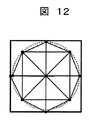
対応点抽出部230では、各特徴点における特徴量を記述し、この特徴量が類似しているかどうかを判定する。この特徴量とは例えば、図12に示すように、特徴点の座標を中心として、中心位置とその周囲の位置の輝度差、及び周囲の位置同士の輝度差を比較、大小で2値化した値をバイナリデータ列として保存した値を特徴量とする。このような特徴量の記述方式は、2値化せずに輝度差分を特徴量としても良い。特徴点を中心とした周囲の画素から特徴量を記述し、そのデータ同士の類似性を利用して左右対応点の探索を対応点抽出部230で実施する。左右で同じ物体の同じコーナーの点は同じ特徴量を持つであろうという考えから、このような特徴量を記述し、対応点の抽出を実施する。これらを比較することで、画像上の同じコーナーにある特徴点の特徴量は類似してくるため、特徴量の比較を実施すると画像上の同じコーナーを判定することができ、左右の対応点が見つかる。
しかしながら、上記の特徴量を利用した対応点探索だけでは、うまくいかない誤対応した点も含まれてしまう可能性がある。まず、簡易的なノイズ対策として、誤対応した点に関しては、左右画像上の大きくずれた位置で対応点をとる可能性がある。このため、誤対応点を簡単に削除する方法の1つとして、簡易ノイズ除去部240では、最初に、対応点が平行化の許容範囲内に入っていないことをもって、誤対応点であることを判定する。特に周囲の点と比較しても画像の上下方向に大きくずれていることを持って、ノイズだと特定を行う。
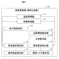
<図4 誤差管理部300>
次に、誤差管理部(幾何と感度)300について説明する。
誤差管理部300では、ステレオカメラに生じる誤差を要因別に解析し、管理する部署である。
次に、誤差管理部(幾何と感度)300について説明する。
誤差管理部300では、ステレオカメラに生じる誤差を要因別に解析し、管理する部署である。
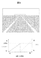
まず、最初に温度管理部310であるが、ここでは温度変化によって生じる平行化誤差と感度誤差の量を推定する。工場でキャリブレーションした際の温度から、カメラを使用中の温度が離れるほど、カメラの筐体への変形の影響や、カメラ撮像素子の感度の変化が大きくなる。これを工場でキャリブレーションした通常温度20度の場合を基準として、撮像素子付近の温度が変化するほど、幾何誤差や感度誤差が大きくなることを事前に調査し、各カメラ共通の傾向が見受けられる場合には、キャリブレーション時からのカメラ使用時の撮像素子付近にある温度計がさす温度に応じて幾何誤差の発生量、感度誤差の発生量を推定する。図13にその例を示す。例えば、各カメラに共通の傾向が認められており、かつ20度キャリブレーション結果を補正したことにより、すべての誤差が0であった場合を示す。幾何系の縦方向のずれ量、横方向のずれ量が0pixelであり、拡大縮小、回転もまったくないとする。感度誤差についても、撮像素子の誤差を計測し、すべて補正済みであり、想定仕様通りの撮像ができる場合には、図13の温度20度のように誤差0となる。走行中に温度変化した場合の誤差増加量を低温-20度の場合と高温60度の場合の誤差量をあらかじめサンプリングされた100台のカメラのデータを基に誤差平均値を求めると共に、傾向が類似していることを確認する。類似していることが確認できた場合には、この表を共通に使えるためサンプリングしてしまった後は、特に計測せずに使いまわすことが可能である。この温度変化時の誤差を表13にまとめる。
更に、温度変化による誤差量が、各カメラの固体に応じて、大きく変化する場合においても図13の表自体は同じであるが、通常キャリブレーション時以外の温度、60度と-20度でも事前に工場でキャリブレーションすることで、その間の温度の際の誤差は線形補完、それ以降は、外挿により推定などをすることで、各個体別の誤差の発生を推定してもよい。
このように、図13の表をベースにして生じる誤差量を推定する。ただし、これも個体ごとの個体差はあったとしても、同一個体が同一温度では同じような誤差が発生する再現性がある場合にのみ利用できる。
このように、図13の表をベースにして生じる誤差量を推定する。ただし、これも個体ごとの個体差はあったとしても、同一個体が同一温度では同じような誤差が発生する再現性がある場合にのみ利用できる。
次に、時間管理部320については工場から出荷時等、もしくはディーラー等でのキャリブレーションや部品メンテナンスからの総経過時間を管理することで、経年劣化による影響を推定するために利用する。レンズの劣化、変色など、走行時や特別な施設なしに補正が困難な項目については、この総経過時間をベースにどの程度、経年劣化が進んだかどうかの推定に利用する。温度変化によるノイズの増加などは、一時的なものかつ、経年劣化とは独立に発生するため、ここでは温度変化によるは考えず、経年劣化による幾何や感度の誤差を管理する手法を示す。
これとは別途、経年変化による左右カメラの位置ずれ、カメラ構造の変形などは、走行中のキャリブレーションによっても補正されるため、出荷時からの総経過時間とは無関係になりやすい。このため図13に示すように、誤差別に時間管理を行う。総経過時間に関しては、共通の時間項目であり同じ時間を○がついている項目で共有した時間を使う。ただし、修理のためにカメラを変更したような場合には総経過時間もキャリブレーション後経過時間もリセットされたものが装着される。また、カメラの修理等で、再検査されたような場合にも管理している時間がリセットされることがある。それ以外の誤差項目ではキャリブレーション後経過時間を基に、誤差量を推定する項目は、キャリブレーション後経過時間の欄に○がつけてある。この項目はキャリブレーションで、補正された場合にリセットされる時間となるため、キャリブレーションの補正が項目別に異なるタイミングで働けば、それぞれリセットされるかどうかが異なる。例えば、幾何の縦方向のキャリブレーションだけを実施した場合には、他のキャリブレーション後経過時間はリセットされず、そのまま経過時間をカウントし続けて幾何縦のキャリブレーション後経過時間のみリセットされる。他、項目についても同様であり、感度オフセットのみキャリブレーションされれば、他項目のキャリブレーション後経過時間はリセットされないような設計となる。ただし、幾何系の外部パラメータ全てを同時にキャリブレーションしたような場合には、カメラの縦横、回転、拡大縮小に全て影響を与えるため、このようなキャリブレーションの場合には、このキャリブレーションによって書き換えられた値に応じて、キャリブレーション後経過時間をリセットするものとする。この場合には、幾何系全てのキャリブレーション後経過時間がリセットされる。時間管理部では、このような走行中キャリブレーションで補正される項目については、走行中キャリブレーションにより補正されてからの経過時間を項目ごとに、管理するものとする。
次に、走行路推定部330では、路面上の凹凸を解析し、その時系列データを解析することで、現在の走行状況は、凹凸が少なく整備された道路なのか、それとも舗装もされていない道路、もしくは穴や落下物のある凹凸路面なのかを推定する。推定された路面の凹凸状況に応じて、左右カメラの幾何状況にどの程度影響するかは、あらかじめ解析しておくことで、幾何に与える影響を推定できるようにしておく。
例えば高速道路のように整備された綺麗な道路では、左右カメラの振動による幾何誤差は小さく、左右対応点の結果からも無視できると判断する。反対に、一般道などでの凹凸路の場合には、左右対応点の結果を観測しながら、走行路がどのような路面であるか同時に推定すると、左右の幾何ずれが毎フレーム縦方向に3pixel程度発生する荒れた路面の道路があったと判定する。この場合、毎フレームごとに誤差が発生することを想定し、キャリブレーション用対応点探索部200により左右対応点が十分に得られた場合には、走行中のキャリブレーション部で補正する補正量は、振動分は補正せずに、時系列データによる振動の平均分の補正値のみを、走行中キャリブレーション部にて補正。反対に、振動に対する補正は、走行路推定部330の推定結果、左右対応点の情報を利用して、そのフレームだけの簡易補正を簡易幾何補正部360にて実施する。もし、瞬間的な左右差が不明な場合には、通常と同様に、1フレームごとに補正を実施するのではなくなく、時系列データを活用する走行中キャリブレーション部500においてキャリブレーションを実施し、ステレオカメラ部100の幾何補正テーブルを幾何補正テーブル生成部140で編集することで、左右カメラの平行性を保つ。ただし、簡易補正部での補正は簡易的であって、回転方向の補正や、拡大縮小方向の補正など、簡易補正では対応しきれない補正がある。このため事前に、簡易補正したとしても、走行路によってどの程度の平行化誤差が発生しそうかというデータは取得し、そのデータを基に、現状の走行路から発生しそうな幾何誤差の想定値を推定することとする。
ステレオカメラの場合には、視差画像が得られるため、自車両前方の進行路を車速と操舵角から推定し、自車両が進行するエリアの視差情報から、自車走行路の路面と車体の相対位置姿勢を時系列に計測し、常に車体がピッチングしているような状況で、その影響をカメラが受けているかどうかなどの判定を実施する。整備された走行路の場合には、相対位置姿勢の変化は小さく、また、視差も安定して検出できる。反対に、カメラ筺体が廉価で、ピッチングによりカメラ筺体までもが変形するような場合には、視差の減少の影響も考えられる。
簡易幾何補正部360では、簡易的な幾何補正のみを実施し、このフレームのみ、もしくは固定フレーム間隔のみの幾何補正を実施する場合に利用し、幾何補正テーブル自体を書き換えるような変更は実施しない。このため、縦、横の補正を基本実施し、複雑なレンズ歪みなどの補正は実施しない。もちろん瞬間的な幾何のずれのため、瞬間的にレンズ歪みが変形することはないため、瞬間的な振動により発生する誤差を抑制する補正部として簡易幾何補正部360を活用する。
更に、幾何誤差推定部370では、温度管理部310、時間管理部320、走行路推定部330により想定される誤差量の総和から、瞬間的に補正された簡易幾何補正部360での補正量を減算して、現フレームに発生しうる最大誤差量を推定する。推定する誤差量は、図13に示している温度変化の場合の誤差増減表と同様に、幾何種類別である、縦、横、拡大縮小、回転のケース別に誤差を管理してもよいし、縦横の位置ずれだけに集約しても良い。また、マッチング手法の縦探索の幅を考慮するのであれば、縦方向の最大ずれ量だけの推定値でも良い。
次に感度系についてまとめる。
既に述べたように温度管理部310においては温度別に発生する誤差量をあらかじめ計測しておき、実際のステレオカメラ利用時の温度に基づいて図14に示すように感度誤差量も推定する。更に時間管理部320においては、総経過時間に基づくレンズの劣化を予測することや、走行中キャリブレー後の経過時間をノイズ種類別に計測し時間を管理する。これによりその経過時間に基づく感度の変化量を推定する。
既に述べたように温度管理部310においては温度別に発生する誤差量をあらかじめ計測しておき、実際のステレオカメラ利用時の温度に基づいて図14に示すように感度誤差量も推定する。更に時間管理部320においては、総経過時間に基づくレンズの劣化を予測することや、走行中キャリブレー後の経過時間をノイズ種類別に計測し時間を管理する。これによりその経過時間に基づく感度の変化量を推定する。
次に、幾何系の誤差には影響しない、光源環境推定部340について記す。光源環境推定部340では、露光調整部120で設定されたカメラシャッター速度とゲイン、画像上の領域別平均輝度などに応じて、画像上のノイズ状況を推定する。シャッター時間が長いほうが、基本的にノイズが少なくなるが、シャッターが長い場合にも画像上の暗い部分にはノイズが多くなりやすく、領域別の平均輝度も利用した上で画像上のノイズ量を推定する。基本的には、カメラの特性をあらかじめ調査しておき、シャッターとゲインに応じたノイズの増加量を種類別に調査しておき、カメラ使用中には、その際の適応露光条件(シャッター速度、ゲイン、周囲の平均輝度)に応じた、ノイズ量を調査しておき、これに基づいたノイズ量を種別に光源環境推定部340にて推定する。
天候推定部350では、ワイパーの動作状況や、外気温、他センサによるガラスの曇り状況や雨滴センサなどによる雨滴付着判断結果から天候状況を予測し、雪や雨などが付着しやすい状況にあるか判断を行う。この天候推定部350の結果に応じて、カメラ撮像時に生じる感度のオフセットやゲイン、ブラーなどに左右差が生じる可能性があると判断する。この場合、他、誤差推定部と異なり雨が降っていたとしても、どのような輝度オフセット、ゲイン、ブラーがどの領域にどのタイミングで生じるか推定することは困難であるため、ここでは発生する可能性が高いと判定するにとどめる。
簡易感度補正部380では、主に短期間に発生した感度誤差のみを対象に簡易的に輝度オフセットやゲインなどの補正を実施する。温度変化や経年変化などに基づくある程度長期の補正については、走行中キャリブレーションにて基本的な対応を実施し、数フレーム間における急激な光源環境の変化が起きた場合のみなどに、簡易的な感度補正にて対応する。露光条件が安定的に変更されていれば、走行中のキャリブレーションで対応するものとする。露光調整用に右画像をベースに平均輝度を監視しているが、左画像でも同様に平均輝度を算出することによって、左右感度の違いを関しており、これをベースに補正量としている。
感度ノイズ推定部390では、温度管理部310、時間管理部320、光源環境推定部340、天候推定部350で推定された誤差量の総和から簡易感度補正部380にて補正された量を減算した量が現状の感度ノイズ量であることを推定する。また、天候推定部350については、感度誤差の可能性があることを情報として管理する。
ここでは、ステレオカメラで発生している左右カメラの誤差を管理するとともに、瞬間的に発生した誤差に対して、簡易的な方法、例えば幾何であれば縦か横のオフセットのみ、感度であれば輝度オフセットか輝度ゲインのみといった限定的な誤差抑制処理を実施し、更に、現状のカメラに簡易補正では抑制しきれなかった誤差、走行中キャリブレーションではまだ対応できていない誤差などを管理する。
<マッチング部>
次に、マッチング部400では、誤差管理部300で推定された幾何誤差と感度誤差の推定結果に応じて、より適切な視差情報が得られるようなマッチング手法を選定する。
次に、マッチング部400では、誤差管理部300で推定された幾何誤差と感度誤差の推定結果に応じて、より適切な視差情報が得られるようなマッチング手法を選定する。
統合管理部410においては、誤差管理部300から得られた現フレームにおける幾何誤差と感度誤差をそれぞれ種別に、誤差量を管理する。図15のマッチングの統合管理テーブルの上から4行目に示す誤差量を種別に毎フレーム更新する。また、推定誤差量を直接情報として得られる場合は、この総量を管理すればよいが、天候検知部の結果のように誤差が発生している可能性を示すような指数の場合には、その可能性の大小に基づいてあらかじめ規定の誤差量を付加して、誤差量を管理するものとする。
3次元を復元するために、特にステレオカメラの場合には、左右カメラが平行に取り付けられているように調整するが、これに誤差が残っている場合や走行中に温度や振動、経年変化などによって生じた左右カメラ間の相対位置姿勢のずれを幾何ノイズとし、この幾何ノイズには、縦ずれ、横ずれ、回転、拡大縮小の4種類を推定する。キャリブレーションを考慮した幾何補正では3軸位置と3軸回転があるが、ここではマッチングに与える影響を考慮して4種類の幾何誤差別に適切なマッチング手法を選択する評価項目として利用する。誤差量で定義している縦Apixelは、画像上で最もずれている画素がApixelであるという推定を基に示している。画像全体がApixel縦ずれではなく、最悪値がApixelという定義方法である。他B,C,Dについても同様で回転などの場合には、画面端や隅でもっとも大きくずれている場所の誤差がCpixelという定義をしている。横や拡大縮小についても同様の定義方法とする。
次に、左右カメラの感度差についても種類別に定義する。ここでは代表的かつマッチング影響を及ぼす5種類の感度ノイズ量を推定し、管理するものとする。感度ノイズの種類は、点ノイズ、線ノイズ、ブラー、オフセット、ゲインであり、それぞれ点ノイズとは画像上にはいる点状のノイズであり、同一輝度の物体を撮像しているにも関わらず周囲の画素と異なる輝度になるような現象であり、非常に暗い状況で、ゲインを上げた撮影時や、極端な高温時、低温時などにそのような点状のノイズが増える、このノイズ量自体はカメラ特性を理解して推定を誤差管理部300で実施している。主に温度管理部310の結果に基づく誤差推定と、光源環境推定部340の露光情報に基づく誤差推定により点状のノイズ量の推定を実施する。
次に線ノイズは、画像上に縦に入るノイズであり、同一の輝度の平面を撮像していてもその縦線上だけ、隣接する線上の画素と異なる輝度になるようなノイズ要因であり、これも極端な温度特性時に発生することがわかっておりカメラ別に異なる量を考慮して、誤差管理部300の温度管理部310にて、位置や強度を計算している。
次に、ブラーはレンズのピントボケのような画像の鮮明さを画像の解像度の特性として数値表現している。誤差管理部310では温度変化や経年劣化、更には、天候による水滴付着などから誤差量を推定している。温度管理部では他のノイズと同様に、温度変化時のブラーの値を図13のテーブルに保持しており、この表をベースに、温度に応じたブラーの程度を推定する。経年劣化に関しても同様に、総経過時間の長さに基づいて、発生するレンズ分解能の低下量をテーブルとしてデータで保持しており、これをベースに現状の分解能低下量を推定する。天候による水滴付着に関しては実際の水滴付着時の解析結果をあらかじめテーブルで保持しており、この水滴付着の可能性があると判断された場合には、そのテーブルに保持された量の分だけぼける可能性があると判断する。これらの推定量を利用して、現フレームにおけるレンズの分解能をしめすブラーの値を推定する。
次に、輝度オフセット、輝度ゲインに関しては、経年劣化や温度変化、露光調整結果を含んだ周囲光源環境からそれぞれ別々に推定する。これらも基本は同様であり、温度特性に関しては図13に示す温度別の誤差量に基づいた推定を実施、経年劣化などに関しては、同様に事前のテーブル表をデータと保持しており、ここから現在の温度や、総経過時間に基づいた誤差量を推定する。反対に、瞬間的な誤差に関しては、誤差管理部の感度ノイズ推定部の結果に基づいて、感度オフセット及び感度ゲインの推定値を利用する。
更に、走行路推定部と光源環境推定部の結果より、現在走行しているシーンを想定し、そのシーンにおいて優れているマッチング手法を選定するために、特定シーンに関しても、幾何ノイズ、感度ノイズと同様にマッチング手法選定のための評価対象とする。特に、特定シーンに関しては、おそらく走行していると推定されるシーンの重みを0から10の重みで表現し、10の場合には強くマッチング手法の選定に影響するという重み付けを表す。感度ノイズ、幾何ノイズも同様に重み付けすることで、どのノイズを重視したステレオマッチング手法を選定するかを決定することができる。本実施例においては、カメラの特性を調査し、事前にこのステレオカメラは幾何ノイズが大きく発生しやすく、幾何誤差がステレオマッチングにより得られる視差画像に与える影響が大きいのか、反対に感度ノイズが大きく発生しやすく、感度誤差がステレオマッチングにより得られる視差画像に与える影響が大きいのか事前に調査し幾何と感度の重要性のバランスをとるとともに、各誤差種別についても発生頻度や誤差量に応じてその重要性を決めておく。もちろんステレオカメラの構造や特性に応じて、この重要性をリアルタイムに変更することでより、感度ノイズに対する評価結果を重要視するような調整、反対に幾何ノイズに対する評価結果を重要視するような調整を行うことで、より適応的な調整を行ってもよい。
本実施例では、安定性などを重視し、幾何ノイズ、感度ノイズの重要性については工場などの出荷前に事前に決定し、特定シーンの重要性のみリアルタイムに変更する方式を選択した。このように、統合管理部410では、幾何ノイズ量と感度ノイズ量をそれぞれ詳細な種別ごとに、そして、感度ノイズ、幾何ノイズ、特定シーンのそれぞれの種別ごとの重要性についての情報を集約する。
ここまでで図15の上側半分の横方向に並ぶ項目を説明した。
次に、テーブルの左側に縦方向に並ぶ項目について説明する。ここは、マッチング部の大半を占める各種マッチング手法の構成内容について示されており、このマッチング手法の基本構成を示している。
次に、テーブルの左側に縦方向に並ぶ項目について説明する。ここは、マッチング部の大半を占める各種マッチング手法の構成内容について示されており、このマッチング手法の基本構成を示している。
横一行ずつに、本フレームでステレオマッチングを実施する際の前処理、後処理を含めたマッチング方式になっており、この横1行で示す前処理後処理含めた一連のマッチング方式が、幾何ノイズ、感度ノイズ、特定シーンに対して、どのようなマッチング性能を示すスコアとなるかを、計算する。
これは横一行目の各セルに対して、まずは幾何ノイズの縦ノイズApixel発生した場合に、どのようなマッチング性能かあらかじめ評価したデータからセルにそのスコアを埋める。縦ノイズの全pixelのデータを持つとかなりのデータ量になるのであれば、所定のpixelの誤差の場合のスコアだけをデータとして保持して、間の誤差が推定された場合には、補間によりスコアを計算しても良い。
このように、各ノイズ別のスコアをそれぞれ計算して横方向にスコアを埋めていく。この場合には、次に、幾何:横ノイズ:Bpixel、幾何:回転:C:pixel、幾何:拡大縮小:D:pixel、に関して、マッチング手法の性能スコアを生める。誤差推定量に応じてマッチングの性能を示すスコアが異なるため、推定誤差の結果が変化するたびに、計算が必要となる。同様に、感度ノイズに関しても、感度ノイズの点ノイズの強度が通常時のE倍になった場合のマッチング性能を示すスコアをセルに埋める。同様に、線ノイズ:F倍、ブラーMTF:G、感度オフセット:H、感度ゲイン:I倍の場合についてもどうように、マッチング手法についてあらかじめ、その誤差が加わった場合のマッチング手法に対する評価結果を事前に取得しておいて、推定された誤差量に応じて、どのようなマッチング性能を示すかをリアルタイムにセルに反映させる。これをすべてのマッチング手法について評価することで、図15に示す、灰色のセルの中のスコアを埋める。
最後に、このスコアを横方向に行別に合計し、最終的な評価点としてもとめ、最高得点の手法が現在のマッチング手法に最も適切であると判断する。
このように推定誤差に対して、それぞれ一連のマッチング手法の性能評価点を計算し集計することで、リアルタイムに変化する推定誤差に対して最も適切なマッチング手法を選定することが可能となり、発生している誤差状態に対して最も性能の良いステレオマッチング結果を得ることが可能となる。
横1行に示す、前処理、後処理を含めたマッチング手法について説明する。
本実施例においてマッチング手法は、前処理、マッチングメイン処理、後処理に分割し、更に、その詳細なON,OFFを含めて管理する。統合管理部においては常に処理を十個することが確定であるノイズ除去フィルタと無効視差判定については、図15の統合管理部での管理対象外としているが、実際のステレオマッチング実行時には、ノイズ除去フィルタ部442と無効視差判定部443にて実施するものとする。
本実施例においてマッチング手法は、前処理、マッチングメイン処理、後処理に分割し、更に、その詳細なON,OFFを含めて管理する。統合管理部においては常に処理を十個することが確定であるノイズ除去フィルタと無効視差判定については、図15の統合管理部での管理対象外としているが、実際のステレオマッチング実行時には、ノイズ除去フィルタ部442と無効視差判定部443にて実施するものとする。
前処理、後処理含めた一連のマッチング手法の、図15の表の上から一つ目の手法は、コントラスト補正有、ノイズ除去有、ステレオマッチング窓サイズ16x16、間引き無、マッチング手法Z、パラメータM,視差の補完無、の手法である。この一連のマッチング手法の際に、幾何ノイズで縦方向に幾何誤差がApixだった場合の評価点をセルに埋める。という処理を実施、次に、横方向の誤差というように順番に、セルを埋める処理を実施、推定誤差に対するこの手法の評価点を計算することができる。次に、同じように、一連のマッチング手法として、コントラスト補正有、ノイズ除去無、ステレオマッチング窓サイズ16x16、1/2間引き、縦探索±1の範囲、ステレオマッチング手法Z,パラメータM、視差の補完無、の場合において、同様に推定誤差に対する評価点を試算、合計となる評価点を計算し、この評価点と各種マッチング手法の評価点を比較することで、どのマッチング手法がより適切かどうかを判断する。
例えば、コントラスト補正され上から2つの手法に関しては、基本は夜間に強い手法であるため、露光条件でのゲインが高い、もしくはカメラの温度が高温もしくは低温時などにノイズが強くかつ低コントラストに強い手法を想定した手法となっている。また、その際の幾何誤差の大小で、少ない場合には上下にステレオマッチングの探査を振らない1つ目の手法が効率よく、2つ目の手法の場合には、ステレオマッチングの探査を実施する。
上から3番目から5番目までの手法は、基本的に感度系のノイズが比較的すくない場合に利用される手法であり、その中で幾何誤差の縦、横のノイズが増えるほど、4番、5番の手法と幾何誤差を吸収しやすい縦方向にステレオマッチングを探査する方法となっている。
上から3番目から5番目までの手法は、基本的に感度系のノイズが比較的すくない場合に利用される手法であり、その中で幾何誤差の縦、横のノイズが増えるほど、4番、5番の手法と幾何誤差を吸収しやすい縦方向にステレオマッチングを探査する方法となっている。
次に、Xのステレオマッチング手法を利用している6番目から8番目の手法は回転誤差に強い手法であり、感度誤差に関しても比較的ロバストである。回転誤差、拡大縮小などの誤差が増えた場合に比較的強い手法であり、この回転の誤差が大きいほど、7,8番とステレオマッチングの探索範囲が縦方向に増えるためにロバストな手法となっている。最後に示す、9番、10番の手法は明るいが低コントラスト、及び、ノイジーな場合に強い評価結果となり、最終的な視差補完が実施されるため、比較的ロバストな実験結果となる。このように一連のステレオマッチング手法ごとに、誤差種別に対する得意、不得意が異なるため、このように誤差種別毎に評価を実施、現フレームにおける発生している推定誤差に応じて、最適なマッチング手法及び組み合わせの前処理、後処理を選定することで、より適切な視差画像を選定することを可能とする。
(前処理)
前処理とは、ステレオマッチングする前に、左右画像に対して、ステレオマッチングの性能が向上するように実施する処理であり、マッチング前処理部420で実施する。コントラスト補正は主に夜間、ノイズ除去は逆光や、高温、低温、夜間などのノイズが増加するときのために用意されている。コントラスト補正部421では、主に夜間用に用意されており、暗くて低コントラストで見えにくい白線や標識、歩行者などを対象に、コントラストを補正することで、認識率の向上を図る手法であり、暗くて見えにくい領域などの立体物などをより抽出しやすくするための処理である。点ノイズ系を削減するために主に利用されるノイズ除去部422を用意しており周辺輝度と大きく変化する画素については周囲の輝度情報から着目画素の輝度を抑制するような処理を実施する。
前処理とは、ステレオマッチングする前に、左右画像に対して、ステレオマッチングの性能が向上するように実施する処理であり、マッチング前処理部420で実施する。コントラスト補正は主に夜間、ノイズ除去は逆光や、高温、低温、夜間などのノイズが増加するときのために用意されている。コントラスト補正部421では、主に夜間用に用意されており、暗くて低コントラストで見えにくい白線や標識、歩行者などを対象に、コントラストを補正することで、認識率の向上を図る手法であり、暗くて見えにくい領域などの立体物などをより抽出しやすくするための処理である。点ノイズ系を削減するために主に利用されるノイズ除去部422を用意しており周辺輝度と大きく変化する画素については周囲の輝度情報から着目画素の輝度を抑制するような処理を実施する。
この表においてすべての機能のON,OFFの組み合わせを用意してもよいが、実際の車載ハードウェアやCPUなどはコストや回路規模、処理時間、発熱による制約が付く場合が多く、またフレームレート内に処理を完了させることを考えるとすべての機能を処理時間がかかるON方向に倒した場合には、規定の処理時間内に処理を完了させることができないなどのことが生じることが懸念される。このため全ての組み合わせを用意するのではなく、あらかじめ設計段階で、お勧めの組み合わせに絞って統合管理部において、その手法群に対する評価をリアルタイムに実施するものとする。
(メイン処理)
マッチングメイン処理部430では、ステレオマッチングの中で、メインとなるマッチング処理を実施するが、マッチング処理する前にさまざまな設定などを決めた後に実施する。まずは縦横のサーチ範囲を縦横 探索範囲設定部431にて実施する。図16にマッチングの基本を示しているが、マッチングのサーチ範囲を横方向の矢印の長さが横探索範囲であり、縦に並ぶ矢印の本数が縦探索範囲として基本的な考え方を示している。統合管理部410にて記された探索範囲±1という記述は、メインの横探索する矢印の上下に1pixel分だけずらして合計3矢印(pixel)分の横探索を実施することを意味する。
マッチングメイン処理部430では、ステレオマッチングの中で、メインとなるマッチング処理を実施するが、マッチング処理する前にさまざまな設定などを決めた後に実施する。まずは縦横のサーチ範囲を縦横 探索範囲設定部431にて実施する。図16にマッチングの基本を示しているが、マッチングのサーチ範囲を横方向の矢印の長さが横探索範囲であり、縦に並ぶ矢印の本数が縦探索範囲として基本的な考え方を示している。統合管理部410にて記された探索範囲±1という記述は、メインの横探索する矢印の上下に1pixel分だけずらして合計3矢印(pixel)分の横探索を実施することを意味する。
マッチング手法設定部432では、統合管理部410によって決められたマッチング手法の動作準備等を実施する。マッチング手法Z,Xを推定された誤差量に基づいて手法ごとにスコア計算し、その合計の評価点によって手法を変更して利用する。
マッチング手法Zの数式とパラメータセットを図18に示す。マッチング手法Zは、マッチングウィンドウ内の輝度差を比較する手法である。ただし、パラメータセットに基づいて、数式が若干変化する。パラメータ調整部435では、ステレオマッチングのパラメータ調整を実施する。本実施例における、マッチング手法によってパラメータは異なるが、主にパラメータ変更するマッチング手法Zのパラメータ変更について図18を利用して説明する。パラメータMの場合には、左右画像の輝度平均値を減算してから輝度差を比較し、その比較結果を絶対値として利用する一般的にZSADという手法を利用する。パラメータNでは、左右画像の輝度平均値は利用しない0として扱い、輝度差の2乗値を輝度差比較に利用する一般的にSSDという手法をとる。パラメータQでは、左右画像の輝度平均値は利用しない0として扱い、輝度差の絶対値を輝度差比較に利用する一般的にSADという手法で対応する。
マッチング手法Xについては、デフォルト設定のパラメータPのみ扱う手法とし、図19にその手法を示す。図19の上から1つ目の式にあるように、マッチングウィンドウ中心との輝度差を0,1として表現する。これは図19の上から2番目の式にあるように、ウィンドウ内の輝度情報を全て0,1のbit列で表現する。左右画像の対応するマッチングウィンドウ内を全てbit列で表現しているので、このbit列同士の類似度をHamming距離で計算する。0と1で表現されたbit列に対して、1bitずつお互いに0同士、もしくは1同士であれば類似しているとして+1、そうでなければ加算しない。このようにbit列の類似度を計算しステレオマッチングする手法である。データ量がかなり削減されることが特徴となり、回路規模もかなり抑制できるために、ノイズ除去手法や、コントラスト補正、視差補間などのほか手法との組み合わせがしやすい手法である。
マッチング窓サイズ部433では、ステレオマッチングする際に利用する画素を特定するために着目画素周囲のマッチングのウィンドウサイズを決定する。図16でいうと四角形のマッチングウィンドウの縦横のpixel数を本実施例では、ベースのサイズとして8x16pixelもしくは16x16pixelのどちらかを統合管理部410の結果から選択する。間引き部434であるが、ここでは統合管理部410によって決められた結果にしたがって、間引きを実施する。図17に示すように、マッチング窓サイズの中でマッチングに利用する画素の間引きを実施する。1/2相当の画素にする場合にも、図17に示すようにさまざまな間引き方があるが、本実施例においては1/2の画素を間引く際のパターンは、縦横の画素のバランスが良く事前評価が良かった1/2斜め間引きを利用する。今回の統合管理部のパターンには用意されていないが1/4のような間引きを利用しても良い。対象の画像の模様によっても異なるが、同じ画素数をマッチングに利用する場合でも、より広い範囲の画素を利用した方が安定することが多く、決められた処理時間や、回路規模である際には、間引きするかわりに、より広い範囲のマッチングウィンドウとすることによりマッチング性能の安定性をたかめることも有効な手段である。もしくは間引きする代わりに縦方向のマッチング探索範囲を増やすことで幾何誤差を吸収する方が、全体として有効な場合もある。
マッチング処理部436では、これまでの、縦横 探索範囲設定部431、マッチング手法設定部432、マッチング窓サイズ部433、間引き部434、パラメータ調整部435において、設定された内容でマッチング処理を実行、結果を保存する。
(後処理)
マッチング後処理部440では、マッチング処理部436で生成された視差画像に対して、後処理を実行する。
視差補間処理部441の視差補間処理においてはその実行の可否を、リアルタイムに変更するため統合管理部においてその実行可否を判断する。視差補間処理とは、着目視差の周囲の視差値と比較し、大きく異なる場合に周囲の視差値から着目視差の値を変更することを実施する処理である。
マッチング後処理部440では、マッチング処理部436で生成された視差画像に対して、後処理を実行する。
視差補間処理部441の視差補間処理においてはその実行の可否を、リアルタイムに変更するため統合管理部においてその実行可否を判断する。視差補間処理とは、着目視差の周囲の視差値と比較し、大きく異なる場合に周囲の視差値から着目視差の値を変更することを実施する処理である。
他に、ノイズ除去フィルタ部442と無効視差判定部443があるが、これらは、リアルタイムに実行の可否を変更せず、常に実施するために、統合管理部410での管理対象外とする。ノイズ除去フィルタとは、マッチングの類似度が信頼に足るものかを判断するフィルタであり、サーチ範囲内のマッチング結果類似度で最も高い類似度以外の部分にも似たような高い類似度が存在するかということから、今回の類似度が明らかに画像の他の部分と比較して、類似しているといえるかどうかということを基準としてノイズかどうかを判断する。無効視差判定部443は、同様に類似度が、低すぎないかどうかということをチェックすることで最も類似しているものの、通常のマッチング度合いと比較して類似度が低すぎて信用できるかどうかということを基準に、類似度が高ければ有効視差、低ければ無効視差と判定する。
<走行中キャリブレーション部>
走行中キャリブレーション部500では、走行中のキャリブレーションを実施する。工場で通常はキャリブレーションするものの、そもそも精度が不十分な場合や、経年劣化、走行中に発生する温度変化により生じる変形、感度変化、更には振動による左右カメラの幾何誤差など、さまざまな要因により左右カメラの整合性が失われる場合がある。走行キャリブレーション部500では、このように走行中に発生した誤差を抑制するために、走行中にキャリブレーションによる補正を実施する。
走行中キャリブレーション部500では、走行中のキャリブレーションを実施する。工場で通常はキャリブレーションするものの、そもそも精度が不十分な場合や、経年劣化、走行中に発生する温度変化により生じる変形、感度変化、更には振動による左右カメラの幾何誤差など、さまざまな要因により左右カメラの整合性が失われる場合がある。走行キャリブレーション部500では、このように走行中に発生した誤差を抑制するために、走行中にキャリブレーションによる補正を実施する。
時系列データ管理部510では、キャリブレーションの基になるデータを管理する。幾何系のデータでいうと、温度変化により、変形する左右カメラの幾何的な歪みに、一定の規則性があるため温度別に変形量を保存しておく。更に温度管理部310から時系列に変化する温度情報を取得し、ここで時系列データとして管理する。キャリブレーション用対応点探索部200からは左右カメラの対応点を取得する。更に、信頼性や精度、安定性向上のためにも、時系列の対応点情報を利用することで、本当に変形しているということの確認や、画面全体からの情報を利用することで精度向上を狙ったキャリブレーションを幾何キャリブレーション部520で実施する。
感度キャリブレーション部530では、温度情報を利用して左右カメラの温度変化が一定以上であること、及びこれがある程度継続的であることを持って、感度補正を実施する。ただし、幾何キャリブレーションも、感度キャリブレーションも温度特性による誤差に完全な再現性がないこと、及び、温度計の温度が完全に変形箇所や撮像素子の温度を計測しているわけではなく、付近の温度を計測しているため、誤差が生じる。このため、走行中キャリブレーションによって簡易的な補正を実施するものの感度誤差も幾何誤差も誤差低減しただけであり、工場キャリブレーション時の温度と離れていると誤差が大きいことにはかわりなく、マッチング手法変更により更なる誤差抑制を実施している。
感度キャリブレーションには、この他に、経年変化による黄変なども対応しているが、徐々にしか進行しないこと、及び各カメラに応じてかなりの誤差が生じることから、この経年変化の時間と、更には、誤差管理部370の感度誤差が常に発生していることをもって感度キャリブレーションにより補正を実施する。このように左右カメラに発生する誤差はさまざまな種別が存在するため、走行中キャリブレーションで吸収できるものは走行中キャリブレーションにより誤差を抑制した上で、残った誤差要因をマッチング吸収する2つの誤差対策を実施する。これにより通常は左右カメラに誤差が発生すると視差情報の欠落や視差精度の低下が生じるがこれをできる限り抑制した密度と精度の高い視差情報をえることができる。実行管理部540では、幾何キャリブレーション部520の結果が従来値と極端に大きく変化しておらず正常で起こりうる範囲内であることなどを確認したうえでキャリブレーションを実行、ステレオカメラ部100の幾何補正テーブル生成部140の修正を実施する。感度キャリブレーションの場合にも同様に、従来値と極端に大きく変化しておらず正常で起こりうる範囲内であることなどを確認したうえでキャリブレーションを実行、ステレオカメラ部100の感度補正部130の補正値を書き換える。また、これらの情報を誤差管理部300にも渡した上で、残誤差の管理に利用する。
<物体検知部>
物体検知部600では、上記、マッチング部で生成された視差画像をベースに、レーン認識、路面推定、立体物抽出、パターン識別による歩行者と車両の識別を実施する。
物体検知部600では、上記、マッチング部で生成された視差画像をベースに、レーン認識、路面推定、立体物抽出、パターン識別による歩行者と車両の識別を実施する。
レーン認識部610では、入力となる右カメラの輝度画像と視差画像を利用して、自車走行路の白線を検出する。画像上の左右の白線を検出することで、左右レーンマークの無限遠交点を求める。これを左右カメラ両方において実施することで、認識の信頼性の向上と共に、左右カメラの幾何ずれの補正にも利用可能である。簡易幾何補正部360や、幾何キャリブレーション部520で、これらの情報を活用して、左右カメラの幾何補正に利用してもよい。
路面推定部620では、視差情報を利用して自車進行路上の視差を解析することで、自車走行路の傾斜や高さの推定に利用する。この路面推定結果に基づいて、この路面より上側に存在する立体物の抽出を、立体物抽出部630で実施する。
パターン認識部640は、立体物抽出部630で抽出された立体物に対して、その立体物が、歩行者であるか車両であるかパターン識別部640にてパターンマッチングにより実施する。
パターンマッチングで識別された車両は、左右カメラの画像上の位置が特定できるため、その左右の画像領域で同一物体を見ているため、感度補正が完全ならば、その領域の輝度分布が完全に同じになるはずである。これらの情報を利用して、簡易感度補正部380や感度キャリブレーション部530で、左右カメラの感度補正を実施してもよい。
<警報制御部>
制御部700では、物体検知部600で実施されたレーン、歩行者、車両、その他、任意立体物の結果に応じて、安全性や利便性を向上するために警報、制御を実施する。まず、レーン認識の結果に関しては、ユーザが制御を実施するか、警報とするか、動作しない状態にするかは自由に選べるため、ユーザの設定に基づいて、警報するか制御するかを切り替える。レーン認識結果を警報する際には、警報部710においてレーン認識の結果と自車挙動の推測結果より、レーンを逸脱しそうな場合には警報を鳴らす。レーン認識結果より制御する際には、制御部720にてレーン認識の結果と自車挙動に基づいて、車両がレーン内から外れないように戻す横方向の制御を実施する。
制御部700では、物体検知部600で実施されたレーン、歩行者、車両、その他、任意立体物の結果に応じて、安全性や利便性を向上するために警報、制御を実施する。まず、レーン認識の結果に関しては、ユーザが制御を実施するか、警報とするか、動作しない状態にするかは自由に選べるため、ユーザの設定に基づいて、警報するか制御するかを切り替える。レーン認識結果を警報する際には、警報部710においてレーン認識の結果と自車挙動の推測結果より、レーンを逸脱しそうな場合には警報を鳴らす。レーン認識結果より制御する際には、制御部720にてレーン認識の結果と自車挙動に基づいて、車両がレーン内から外れないように戻す横方向の制御を実施する。
立体物の歩行者や車両の場合には、立体物の位置や速度と自車両の進行路及び衝突予測時間に基づいて、警報や制御を実施する。立体物に関しては、衝突の可能性が高い場合には警報、更に車両が立体物に接近し、必ず衝突すると判断した場合には制御を実施する。
ユーザによる警報や、制御のON,OFFは可能とする。
ユーザによる警報や、制御のON,OFFは可能とする。
ギブアップ部730では、誤差管理部300の結果に基づいて、左右カメラの幾何誤差、もししくは感度誤差が許容範囲を超えた場合には、システム全体をギブアップさせる。
反対に例えば高温だったカメラが冷えて通常温度に安定的に戻ったことが判断できれば、ギブアップの解除なども実施する。
反対に例えば高温だったカメラが冷えて通常温度に安定的に戻ったことが判断できれば、ギブアップの解除なども実施する。
<図20 処理フローチャート>
S01
まず、ステレオカメラで左右画像を撮像する。
S01
まず、ステレオカメラで左右画像を撮像する。
S02
右画像を中心に解析し、シャッター速度、ゲインの露光調整を実施。
右画像を中心に解析し、シャッター速度、ゲインの露光調整を実施。
S03
工場でのキャリブレーション結果もしくは、走行中のキャリブレーション結果に基づいた幾何補正量を計算。補正前の準備を実施。
工場でのキャリブレーション結果もしくは、走行中のキャリブレーション結果に基づいた幾何補正量を計算。補正前の準備を実施。
S04
ステレオ視するための画像を生成。
ステレオ視するための画像を生成。
S05
左右画像から左右対応点抽出を実施。左右の幾何誤差を計測するために利用する。
瞬間的な補正にも利用可能だが、簡易的な補正で誤差が残る、簡易幾何補正S09で利用する。
長期的な補正のために、精度は良いが、瞬間的な幾何の歪みには対応できない時系列の対応点から走行中幾何キャリブレーションS16で利用する。
左右画像から左右対応点抽出を実施。左右の幾何誤差を計測するために利用する。
瞬間的な補正にも利用可能だが、簡易的な補正で誤差が残る、簡易幾何補正S09で利用する。
長期的な補正のために、精度は良いが、瞬間的な幾何の歪みには対応できない時系列の対応点から走行中幾何キャリブレーションS16で利用する。
S06
温度誤差の推定。撮像素子付近の温度計で計測された温度を利用して、この温度に基づく幾何と感度の誤差量を推定する。
温度誤差の推定。撮像素子付近の温度計で計測された温度を利用して、この温度に基づく幾何と感度の誤差量を推定する。
S07
時間誤差の推定。経年劣化などにより生じる時間的な感度、幾何誤差を推定。
時間誤差の推定。経年劣化などにより生じる時間的な感度、幾何誤差を推定。
S08
走行路からカメラに発生する振動など、幾何誤差を推定
S09
簡易幾何補正では、ここで画像を編集することは処理負荷も高く、2度目の画像編集となり画質劣化、処理負荷増大につながってしまうため、6軸の幾何補正ではなく、簡易的に補正可能な縦と横の幾何補正のみを実施する。
走行路からカメラに発生する振動など、幾何誤差を推定
S09
簡易幾何補正では、ここで画像を編集することは処理負荷も高く、2度目の画像編集となり画質劣化、処理負荷増大につながってしまうため、6軸の幾何補正ではなく、簡易的に補正可能な縦と横の幾何補正のみを実施する。
S10
推定した幾何ノイズの総合計量から簡易幾何補正で補正された誤差量を現在し、また、走行中キャリブレーションにより補正された場合にもそれを反映した幾何誤差を推定する。
推定した幾何ノイズの総合計量から簡易幾何補正で補正された誤差量を現在し、また、走行中キャリブレーションにより補正された場合にもそれを反映した幾何誤差を推定する。
S11
光源環境誤差推定では、露光条件、画像上の輝度値から予想される画像上の感度ノイズ量の推定を実施する。
光源環境誤差推定では、露光条件、画像上の輝度値から予想される画像上の感度ノイズ量の推定を実施する。
S12
天候を予測し、雨天時などのフロントガラスに付着する水滴によるブラーなどが発生するかどうかを推定する。
天候を予測し、雨天時などのフロントガラスに付着する水滴によるブラーなどが発生するかどうかを推定する。
S13
簡易感度補正では、左右の感度オフセットやゲインのオフセットのみの補正を実施する。
簡易感度補正では、左右の感度オフセットやゲインのオフセットのみの補正を実施する。
S14
感度ノイズの推定では、推定された感度ノイズの総計から、簡易補正量分を差し引いた感度誤差量を推定する。
感度ノイズの推定では、推定された感度ノイズの総計から、簡易補正量分を差し引いた感度誤差量を推定する。
S15
左右対応点の時系列データを保存して、露光調整部に計測された、左右画像の平均輝度を活用する。
左右対応点の時系列データを保存して、露光調整部に計測された、左右画像の平均輝度を活用する。
S16
左右対応点の時系列データを活用することで、画像上、及び3次元空間上に分散した左右対応点を利用して、幾何キャリブレーションを実施する。ここで利用する際には、毎フレーム発生するような振動が発生しているか発生していない状況かはあらかじめ判断する。
左右対応点の時系列データを活用することで、画像上、及び3次元空間上に分散した左右対応点を利用して、幾何キャリブレーションを実施する。ここで利用する際には、毎フレーム発生するような振動が発生しているか発生していない状況かはあらかじめ判断する。
S17
感度キャリブレーションでは、左右画像のシャッターやゲインはそろえているが実際の画像の輝度分布がどのような状況にあるかを解析している。このため、左右の画像の輝度分布により感度のオフセットやゲインの補正が必要か、かつ補正量を推定する。
感度キャリブレーションでは、左右画像のシャッターやゲインはそろえているが実際の画像の輝度分布がどのような状況にあるかを解析している。このため、左右の画像の輝度分布により感度のオフセットやゲインの補正が必要か、かつ補正量を推定する。
S18
幾何誤差、感度誤差が時系列的に安定して発生、なおかつこれが高信頼であることが確定された場合に、走行中キャリブレーションとして補正を実施する。
また、幾何誤差であっても毎フレーム左右カメラに振動が発生しているような場合には、振動が発生していることを確認し、更には、その振動の中心となるような幾何誤差量を推定することで補正を実施する。
幾何誤差、感度誤差が時系列的に安定して発生、なおかつこれが高信頼であることが確定された場合に、走行中キャリブレーションとして補正を実施する。
また、幾何誤差であっても毎フレーム左右カメラに振動が発生しているような場合には、振動が発生していることを確認し、更には、その振動の中心となるような幾何誤差量を推定することで補正を実施する。
S19
幾何誤差と感度誤差の推定値に対して、もっとも適切なマッチング手法が何かを図16に示すテーブルの各セルのスコアを計算し、集計することで評価点を計算。もっとも優れている手法を選定する。
幾何誤差と感度誤差の推定値に対して、もっとも適切なマッチング手法が何かを図16に示すテーブルの各セルのスコアを計算し、集計することで評価点を計算。もっとも優れている手法を選定する。
S20
選定されたステレオマッチング手法を利用してステレオマッチングを実行する。
選定されたステレオマッチング手法を利用してステレオマッチングを実行する。
S21
レーン認識、路面推定、立体物抽出、パターン識別を実施する。
レーン認識、路面推定、立体物抽出、パターン識別を実施する。
S22
上記、認識結果を利用して、予防安全に関する警報、及び制御を実施する。
上記、認識結果を利用して、予防安全に関する警報、及び制御を実施する。
以上説明した本実施例の車載環境認識装置によれば、ステレオマッチングにより3次元形状を解析する再に、マッチングウィンドウ内におけるテクスチャの偏りにより、求められる3次元形状に誤差が計測されることがある。このため、マッチングウィンドウ内のテクスチャを解析することで誤差が発生するマッチングウィンドウを特定し、この誤差による影響を抑制するために、計測店を削除、もしくはマッチングウィンドウを再分割する詳細計測、もしくは計測点の補正を実施し、この計測結果に基づいて警報、速度制御、サスペンション制御を実施する。
本実施例の車載周囲環境認識装置は、下記のように表現することができる。
撮像部を有する車載周囲環境認識装置であって、前記撮像部の視点に基づき3次元形状を得る際に前記撮像部の誤差を推定する誤差管理部と、該誤差管理部の推定結果に応じてマッチング手法を選定するマッチング部と、有する。
また、前記誤差管理部は、誤差の種別と量を管理する。
また、前記誤差の種別は、幾何の誤差を含み、該幾何の誤差は、縦位置、横位置、回転、拡大及び縮小のいずれか1つを含む。
また、前記誤差の種別は、感度の誤差を含み、該感度の誤差は、点ノイズ、線ノイズ、ブラー、感度オフセット及び感度ゲインのいずれか1つを含む。
また、像部を左右にそれぞれ有し、前記幾何の誤差を左右対応点若しくは左右対応する線情報によって補正し、該補正で残った誤差量を前記誤差管理部で推定し、該誤差量は縦方向を含めたステレオマッチング処理をする。
また、像部を左右にそれぞれ有し、前記左右の前記撮像部で撮像された左右対応点から前記幾何の誤差を推定し、継時的なゆがみ又は振動の発生を特定する。
また、な誤差量と長期的な誤差量とを分類し、前記長期的な誤差量は、左右対応点データを活用してキャリブレーションで誤差を補正して残誤差が少なくなるようにして、前記短期的な誤差及び前記残誤差は、縦方向及び横方向の前記幾何の誤差の補正と、複数のステレオマッチング処理から前記幾何の誤差に適する前記ステレオマッチング処理を選定して実行する。
また、前記撮像部に内蔵された温度センサに基づいて、撮像素子の温度変化を予測し、 前記誤差管理部は、前記温度センサが予測した温度に基づいて前記誤差を推定する。
また、走行路面の凹凸状況を推定する路面状況推定部を有し、前記幾何の誤差を推定する。
また、前記撮像部の露光情報に基づいて、前記感度の誤差を予測する。
また、前記マッチング手法は、コントラスト補正、ノイズ除去、マッチングウィンドウサイズ、マッチングウィンドウ内の間引き、探索範囲、マッチング手法、パラメータ及び視差補間の少なくともいずれかを変更する。
本実施例の車載環境認識装置によれば、車両に設置された複数台のカメラを利用して、3次元形状を復元する際に、時間によって変化する複数台カメラ間の相対幾何誤差、及び感度誤差を管理し、長時間かけて発生する誤差はキャリブレーションによって誤差を抑制し、残誤差に関してはこれを許容するマッチング手法を選定することで、より高精度で高密度な3次元形状の復元と、それを基にして認識される物体の認識率を向上させることを可能とする。
100 ステレオカメラ部
110 撮像部
120 露光調整部
130 感度補正部
140 幾何補正テーブル生成部
150 ステレオ用画像生成部
200 キャリブレーション用対応点探索部
210 処理領域決定部
220 左右特徴点抽出部
230 対応点抽出部
240 ノイズ除去部
300 誤差管理部(幾何と感度)
310 温度管理部
320 時間管理部
330 走行路推定部
340 光源環境推定部
350 天候推測部
360 簡易幾何補正部
370 平行化誤差推定部
380 簡易感度補正部
390 感度ノイズ推定部
400 マッチング部
410 統合管理部
420 マッチング前処理部
421 コントラスト補正部
422 ノイズ除去部
423 感度補正部
430 マッチングメイン処理部
431 縦横探索範囲設定部
432 マッチング手法設定部
433 マッチング窓サイズ部
434 間引きパターン設定部
435 パラメータ調整部
436 マッチング処理部
440 マッチング後処理部
441 視差補間処理部
442 ノイズ除去フィルタ部
443 無効視差判定部
500 走行中キャリブレーション部
510 時系列データ管理部
520 幾何キャリブレーション部
530 感度キャリブレーション部
540 実行管理部
600 物体検知部
610 レーン認識部
620 路面推定部
630 立体物抽出部
640 パターン識別部
700 警報制御部
710 警報部
720 制御部
730 ギブアップ部
Claims (11)
- 撮像部を有する車載周囲環境認識装置であって、
前記撮像部の視点に基づき3次元形状を得る際に前記撮像部の誤差を推定する誤差管理部と、
該誤差管理部の推定結果に応じてマッチング手法を選定するマッチング部と、を有することを特徴とする車載周囲環境認識装置。 - 前記誤差管理部は、誤差の種別と量を管理することを特徴とする、請求項1記載の車載周囲環境認識装置。
- 前記誤差の種別は、幾何の誤差を含み、該幾何の誤差は、縦位置、横位置、回転、拡大及び縮小のいずれか1つを含むことを特徴とする、請求項2記載の車載周囲環境認識装置。
- 前記誤差の種別は、感度の誤差を含み、該感度の誤差は、点ノイズ、線ノイズ、ブラー、感度オフセット及び感度ゲインのいずれか1つを含むことを特徴とする、請求項2記載の車載周囲環境認識装置。
- 前記撮像部を左右にそれぞれ有し、前記幾何の誤差を左右対応点若しくは左右対応する線情報によって補正し、該補正で残った誤差量を前記誤差管理部で推定し、該誤差量は縦方向を含めたステレオマッチング処理をすることを特徴とする、請求項3記載の車載周囲環境認識装置。
- 前記撮像部を左右にそれぞれ有し、前記左右の前記撮像部で撮像された左右対応点から前記幾何の誤差を推定し、継時的なゆがみ又は振動の発生を特定することを特徴とする、請求項3記載の車載周囲環境認識装置。
- 短期的な誤差量と長期的な誤差量とを分類し、
前記長期的な誤差量は、左右対応点データを活用してキャリブレーションで誤差を補正して残誤差が少なくなるようにして、 前記短期的な誤差及び前記残誤差は、縦方向及び横方向の前記幾何の誤差の補正と、複数のステレオマッチング処理から前記幾何の誤差に適する前記ステレオマッチング処理を選定して実行することを特徴とする、請求項3記載の車載周囲環境認識装置。 - 前記撮像部に内蔵された温度センサに基づいて、撮像素子の温度変化を予測し、
前記誤差管理部は、前記温度センサが予測した温度に基づいて前記誤差を推定することを特徴とする、請求項1記載の車載周囲環境認識装置。 - 走行路面の凹凸状況を推定する路面状況推定部を有し、前記幾何の誤差を推定することを特徴とする、請求項3記載の車載周囲環境認識装置。
- 前記撮像部の露光情報に基づいて、前記感度の誤差を予測することを特徴とする、請求項4記載の車載周囲環境認識装置。
- 前記マッチング手法は、コントラスト補正、ノイズ除去、マッチングウィンドウサイズ、マッチングウィンドウ内の間引き、探索範囲、マッチング手法、パラメータ及び視差補間の少なくともいずれかを変更することを特徴とする、請求項1記載の車載周囲環境認識装置。
Priority Applications (1)
| Application Number | Priority Date | Filing Date | Title |
|---|---|---|---|
| EP18837511.7A EP3624064A4 (en) | 2017-07-28 | 2018-07-19 | VEHICLE MOUNTED ENVIRONMENTAL RECOGNITION DEVICE |
Applications Claiming Priority (2)
| Application Number | Priority Date | Filing Date | Title |
|---|---|---|---|
| JP2017-146052 | 2017-07-28 | ||
| JP2017146052A JP6997551B2 (ja) | 2017-07-28 | 2017-07-28 | 車載環境認識装置 |
Publications (1)
| Publication Number | Publication Date |
|---|---|
| WO2019021925A1 true WO2019021925A1 (ja) | 2019-01-31 |
Family
ID=65040560
Family Applications (1)
| Application Number | Title | Priority Date | Filing Date |
|---|---|---|---|
| PCT/JP2018/027036 WO2019021925A1 (ja) | 2017-07-28 | 2018-07-19 | 車載環境認識装置 |
Country Status (3)
| Country | Link |
|---|---|
| EP (1) | EP3624064A4 (ja) |
| JP (1) | JP6997551B2 (ja) |
| WO (1) | WO2019021925A1 (ja) |
Cited By (1)
| Publication number | Priority date | Publication date | Assignee | Title |
|---|---|---|---|---|
| CN112947516A (zh) * | 2021-02-02 | 2021-06-11 | 三亚海兰寰宇海洋信息科技有限公司 | 一种船舶运动状态判别方法及系统 |
Families Citing this family (2)
| Publication number | Priority date | Publication date | Assignee | Title |
|---|---|---|---|---|
| WO2023170910A1 (ja) * | 2022-03-11 | 2023-09-14 | 日立Astemo株式会社 | 外界認識装置、および、外界認識方法 |
| WO2024047845A1 (ja) * | 2022-09-01 | 2024-03-07 | 三菱電機ビルソリューションズ株式会社 | 監視カメラの撮影データの欠陥検知装置、欠陥検知方法、及び欠陥検知プログラム |
Citations (3)
| Publication number | Priority date | Publication date | Assignee | Title |
|---|---|---|---|---|
| JP2003227725A (ja) * | 2002-02-04 | 2003-08-15 | Clarion Co Ltd | 車載ナビゲーションシステム及びナビゲーション方法並びにナビゲーション用プログラム |
| JP2013508844A (ja) * | 2009-10-20 | 2013-03-07 | トタル・イメルジヨン | 画像のシーケンス内のオブジェクトのリアルタイム表現のハイブリッド型追跡のための方法、コンピュータプログラム、および装置 |
| JP2014074632A (ja) | 2012-10-03 | 2014-04-24 | Isuzu Motors Ltd | 車載ステレオカメラの校正装置及び校正方法 |
Family Cites Families (5)
| Publication number | Priority date | Publication date | Assignee | Title |
|---|---|---|---|---|
| EP1637836A1 (en) * | 2003-05-29 | 2006-03-22 | Olympus Corporation | Device and method of supporting stereo camera, device and method of detecting calibration, and stereo camera system |
| JP2004354236A (ja) * | 2003-05-29 | 2004-12-16 | Olympus Corp | ステレオカメラ支持装置およびステレオカメラ支持方法ならびにステレオカメラシステム |
| JP6221464B2 (ja) * | 2013-07-26 | 2017-11-01 | 株式会社リコー | ステレオカメラ装置、移動体制御システム及び移動体、並びにプログラム |
| JP6537385B2 (ja) * | 2015-07-17 | 2019-07-03 | 日立オートモティブシステムズ株式会社 | 車載環境認識装置 |
| JPWO2017042998A1 (ja) * | 2015-09-07 | 2018-06-28 | パナソニックIpマネジメント株式会社 | 車載用ステレオカメラ装置、およびその補正方法 |
-
2017
- 2017-07-28 JP JP2017146052A patent/JP6997551B2/ja active Active
-
2018
- 2018-07-19 WO PCT/JP2018/027036 patent/WO2019021925A1/ja unknown
- 2018-07-19 EP EP18837511.7A patent/EP3624064A4/en active Pending
Patent Citations (3)
| Publication number | Priority date | Publication date | Assignee | Title |
|---|---|---|---|---|
| JP2003227725A (ja) * | 2002-02-04 | 2003-08-15 | Clarion Co Ltd | 車載ナビゲーションシステム及びナビゲーション方法並びにナビゲーション用プログラム |
| JP2013508844A (ja) * | 2009-10-20 | 2013-03-07 | トタル・イメルジヨン | 画像のシーケンス内のオブジェクトのリアルタイム表現のハイブリッド型追跡のための方法、コンピュータプログラム、および装置 |
| JP2014074632A (ja) | 2012-10-03 | 2014-04-24 | Isuzu Motors Ltd | 車載ステレオカメラの校正装置及び校正方法 |
Non-Patent Citations (1)
| Title |
|---|
| See also references of EP3624064A4 |
Cited By (2)
| Publication number | Priority date | Publication date | Assignee | Title |
|---|---|---|---|---|
| CN112947516A (zh) * | 2021-02-02 | 2021-06-11 | 三亚海兰寰宇海洋信息科技有限公司 | 一种船舶运动状态判别方法及系统 |
| CN112947516B (zh) * | 2021-02-02 | 2022-10-21 | 三亚海兰寰宇海洋信息科技有限公司 | 一种船舶运动状态判别方法及系统 |
Also Published As
| Publication number | Publication date |
|---|---|
| JP2019028633A (ja) | 2019-02-21 |
| JP6997551B2 (ja) | 2022-01-17 |
| EP3624064A4 (en) | 2021-02-24 |
| EP3624064A1 (en) | 2020-03-18 |
Similar Documents
| Publication | Publication Date | Title |
|---|---|---|
| US10567704B2 (en) | Method for motion estimation between two images of an environmental region of a motor vehicle, computing device, driver assistance system as well as motor vehicle | |
| US9378553B2 (en) | Stereo image processing device for vehicle | |
| RU2529594C1 (ru) | Устройство калибровки, система измерения расстояния, способ калибровки и программа калибровки | |
| EP1918853B1 (en) | Lane marker detection and fitting | |
| US9934442B2 (en) | Passenger counting device, passenger counting method, and program recording medium | |
| US9228833B2 (en) | Wide baseline binocular object matching method using minimal cost flow network | |
| US9794543B2 (en) | Information processing apparatus, image capturing apparatus, control system applicable to moveable apparatus, information processing method, and storage medium of program of method | |
| JP6458651B2 (ja) | 路面標示検出装置及び路面標示検出方法 | |
| JP2010537331A (ja) | ビデオ画像のオンライン較正方法およびシステム | |
| WO2019021925A1 (ja) | 車載環境認識装置 | |
| WO2014002692A1 (ja) | ステレオカメラ | |
| US7987052B2 (en) | Method for evaluation, by motor vehicle, of the characteristics of a front element | |
| CN112261390B (zh) | 车载摄像设备及其图像优化装置和优化方法 | |
| JP6970568B2 (ja) | 車両の周辺監視装置と周辺監視方法 | |
| JP6635621B2 (ja) | 自動車用視覚システム及び視覚システムを制御する方法 | |
| KR101995466B1 (ko) | 특징점을 이용한 스테레오 카메라의 이미지 매칭 방법 및 장치 | |
| JP7182195B2 (ja) | ダブルタイヤ判定装置、及びダブルタイヤ判定方法 | |
| WO2014050285A1 (ja) | ステレオカメラ装置 | |
| JP2015143657A (ja) | 車両のステレオカメラシステム | |
| CN113066133A (zh) | 一种基于路面标识几何特征的车载摄像头在线自标定方法 | |
| JP6704307B2 (ja) | 移動量算出装置および移動量算出方法 | |
| JP6334773B2 (ja) | ステレオカメラ | |
| KR102327342B1 (ko) | 차량용 카메라 보정 장치 | |
| Van Crombrugge et al. | Fast Ground Detection for Range Cameras on Road Surfaces Using a Three-Step Segmentation | |
| Van Barel et al. | Fast Ground Detection for Range Cameras on Road Surfaces Using a Three-Step Segmentation |
Legal Events
| Date | Code | Title | Description |
|---|---|---|---|
| 121 | Ep: the epo has been informed by wipo that ep was designated in this application |
Ref document number: 18837511 Country of ref document: EP Kind code of ref document: A1 |
|
| ENP | Entry into the national phase |
Ref document number: 2018837511 Country of ref document: EP Effective date: 20191211 |
|
| NENP | Non-entry into the national phase |
Ref country code: DE |