WO2019021681A1 - Air conditioning device - Google Patents
Air conditioning device Download PDFInfo
- Publication number
- WO2019021681A1 WO2019021681A1 PCT/JP2018/023011 JP2018023011W WO2019021681A1 WO 2019021681 A1 WO2019021681 A1 WO 2019021681A1 JP 2018023011 W JP2018023011 W JP 2018023011W WO 2019021681 A1 WO2019021681 A1 WO 2019021681A1
- Authority
- WO
- WIPO (PCT)
- Prior art keywords
- air
- unit
- control
- vehicle
- particle
- Prior art date
Links
Images


Classifications
-
- B—PERFORMING OPERATIONS; TRANSPORTING
- B01—PHYSICAL OR CHEMICAL PROCESSES OR APPARATUS IN GENERAL
- B01D—SEPARATION
- B01D46/00—Filters or filtering processes specially modified for separating dispersed particles from gases or vapours
- B01D46/42—Auxiliary equipment or operation thereof
- B01D46/44—Auxiliary equipment or operation thereof controlling filtration
-
- B—PERFORMING OPERATIONS; TRANSPORTING
- B60—VEHICLES IN GENERAL
- B60H—ARRANGEMENTS OF HEATING, COOLING, VENTILATING OR OTHER AIR-TREATING DEVICES SPECIALLY ADAPTED FOR PASSENGER OR GOODS SPACES OF VEHICLES
- B60H1/00—Heating, cooling or ventilating [HVAC] devices
- B60H1/32—Cooling devices
-
- B—PERFORMING OPERATIONS; TRANSPORTING
- B60—VEHICLES IN GENERAL
- B60H—ARRANGEMENTS OF HEATING, COOLING, VENTILATING OR OTHER AIR-TREATING DEVICES SPECIALLY ADAPTED FOR PASSENGER OR GOODS SPACES OF VEHICLES
- B60H3/00—Other air-treating devices
-
- B—PERFORMING OPERATIONS; TRANSPORTING
- B60—VEHICLES IN GENERAL
- B60H—ARRANGEMENTS OF HEATING, COOLING, VENTILATING OR OTHER AIR-TREATING DEVICES SPECIALLY ADAPTED FOR PASSENGER OR GOODS SPACES OF VEHICLES
- B60H3/00—Other air-treating devices
- B60H3/06—Filtering
Definitions
- the present disclosure relates to an air conditioner installed in a vehicle.
- An air conditioner mounted on a vehicle is a device that adjusts the temperature of air taken in from the vehicle interior or the outside of the vehicle and blows out the temperature-adjusted air into the vehicle interior as conditioned air.
- it has also been considered to provide an air conditioner with a function of reducing the concentration of particles (for example, pollen, PM 2.5, etc.) drifting in the air in a vehicle cabin.
- Patent No. 431270 gazette
- the humidity of the vehicle compartment is excessively increased and fogging occurs on the window of the vehicle There is.
- the concentration of carbon dioxide in the passenger compartment may gradually increase, causing the occupants to feel uncomfortable.
- An object of the present disclosure is to provide an air conditioner capable of preventing occurrence of fogging or the like on a window of a vehicle while reducing particle concentration in a vehicle interior.
- An air conditioner is an air conditioner installed in a vehicle, and includes an air conditioning unit that adjusts a temperature of air blown out into a vehicle cabin of the vehicle, and an air supplied to the air conditioning unit from the outside of the vehicle.
- an air conditioning unit that adjusts a temperature of air blown out into a vehicle cabin of the vehicle, and an air supplied to the air conditioning unit from the outside of the vehicle.
- a filter for removing particles from air supplied to the air conditioning unit, a blower for sending out the air so as to pass through the filter and the air conditioning unit, and a control unit for controlling the operation of the inside / outside air adjustment unit and the blower Prepare.
- the control unit is configured to adjust the flow rate of air introduced from the outside air introduction unit when performing particle reduction control, which is control to increase the flow rate of air passing through the filter.
- Such an air conditioner can perform particle reduction control.
- the particle reduction control is control to increase the number of particles collected per unit time in the filter by increasing the flow rate of air passing through the filter. By performing such particle reduction control as necessary, it is possible to reduce the concentration of particles in the air in the vehicle compartment.
- the control unit adjusts the flow rate of air introduced from the outside air introduction unit. That is, the control unit performs particle reduction control while introducing an appropriate amount of air (outside air) from the outside air introduction unit as needed, thereby preventing the humidity and carbon dioxide concentration in the vehicle compartment from becoming too high. can do. As a result, it is possible to prevent fogging and the like on the window of the vehicle while reducing the particle concentration in the vehicle compartment.
- an air conditioner capable of preventing fogging and the like on the window of the vehicle while reducing the particle concentration in the vehicle interior.
- FIG. 1 is a view schematically showing the overall configuration of the air conditioner according to the present embodiment.
- FIG. 2 is a flowchart showing the flow of processing executed by the control device.
- FIG. 3 is a flowchart showing the flow of processing executed by the control device.
- FIG. 4 is a flowchart showing the flow of processing executed by the control device.
- FIG. 5 is a flowchart showing the flow of processing executed by the control device.
- FIG. 6 is a diagram showing an example of the time change of each of the particle concentration and the blower rotation number.
- FIG. 7 is a flowchart showing the flow of processing executed by the control device.
- the air conditioner 10 which concerns on this embodiment is demonstrated, referring FIG.
- the air conditioner 10 is a device mounted on a vehicle (the whole is not shown), and is configured as a device for performing temperature control of air in a cabin of the vehicle, that is, air conditioning.
- the air conditioner 10 includes an air conditioning case 200, a blower 250, a filter 240, an air conditioning unit 260, a concentration detection unit 291, and a control device 100.
- the air conditioning case 200 is a tubular member for guiding the air to be air conditioned into the vehicle compartment. Inside the air conditioning case 200, the air flows from the left side to the right side in FIG. In the air conditioning case 200, an outside air introducing unit 220, an inside air introducing unit 210, a face duct 270, and a foot duct 280 are formed.
- the outside air introducing unit 220 is a portion serving as an inlet for introducing air supplied to the air conditioning unit 260 described later from the outside of the vehicle to the inside of the air conditioning case 200.
- the inside air introducing unit 210 is a portion serving as an inlet for introducing the air supplied to the air conditioning unit 260 from the vehicle interior to the inside of the air conditioning case 200.
- the inside air introducing unit 210 and the outside air introducing unit 220 are formed to be aligned in the upstream side portion of the air conditioning case 200.
- An inside / outside air switching door 230 is provided between the outside air introducing unit 220 and the inside air introducing unit 210.
- the inside / outside air switching door 230 is a door for adjusting the amount of air introduced from each of the outside air introducing unit 220 and the inside air introducing unit 210, and corresponds to the “inside / outside air adjusting unit” in the present embodiment.
- the air introduced from the outside air introducing unit 220 is hereinafter also referred to as "outside air”. Moreover, the thing of the air introduced from the inside air introduction part 210 is described also as “inner air” below. As shown in FIG. 1, when the outside air introduction unit 220 is completely closed, only inside air is introduced into the air conditioning unit 260 and outside air is not introduced. The operation of the inside / outside air switching door 230 is controlled by the control device 100 described later.
- the actuator of the inside / outside air switching door 230 incorporates an opening degree sensor (not shown) for detecting the opening degree of the inside / outside air switching door 230 at the present time.
- the opening degree of the inside / outside air switching door 230 detected by the opening degree sensor is transmitted to the control device 100.
- the face duct 270 and the foot duct 280 are both exhaust ports for introducing the conditioned air into the vehicle compartment.
- the face duct 270 and the foot duct 280 are formed on the downstream side of the air conditioning case 200.
- the face duct 270 is connected to a face outlet (not shown) for blowing conditioned air toward the face of the occupant.
- the foot duct 280 is connected to a foot outlet (not shown) for blowing conditioned air toward the feet of the occupant.
- a face door 271 is provided at the inlet of the face duct 270.
- conditioned air is supplied from the face duct 270 toward the face outlet.
- a foot door 281 is provided at the inlet of the foot duct 280.
- conditioned air is supplied from the foot duct 280 toward the foot outlet.
- the operations of the face door 271 and the foot door 281 are controlled by the control device 100.
- downstream side of the face duct 270 may be branched into two, and one of them may be connected to a defroster outlet (not shown) formed in the vicinity of the window.
- the blower 250 is a blower for delivering air to the downstream side inside the air conditioning case 200. Air delivered by the blower 250 is blown out into the vehicle cabin through the filter 240 and the air conditioner 260 in order.
- the rotational speed of the blower 250 that is, the air volume of the conditioned air blown out from the air conditioner 10 into the vehicle cabin is controlled by the control device 100.
- the filter 240 is a filter for removing particles contained in the air from the air supplied to the air conditioning unit through the air conditioning case 200.
- the filter 240 is provided on the downstream side of the inside air introducing unit 210 and the outside air introducing unit 220 and on the upstream side of the blower 250.
- the particles removed by the filter 240 may be, for example, fine particles such as PM 2.5, or may be pollen, dust, or the like.
- the air conditioning unit 260 is a part that adjusts the temperature of the air blown out into the vehicle compartment and thereby generates the conditioned air.
- the temperature of air is adjusted by heat exchange with a refrigerant or the like.
- the air conditioning unit 260 is provided downstream of the blower 250 and upstream of the face duct 270 and the foot duct 280.
- the air conditioning unit 260 includes an evaporator for dehumidifying and cooling the air, a heater core for heating the air, an air mix door for adjusting the flow rate of the air passing through them, a compressor for circulating the refrigerant, and the like. (All not shown) are provided.
- the specific illustration and description are abbreviate
- the concentration detection unit 291 is a sensor for detecting the concentration of particles in the air in the vehicle compartment. As shown in FIG. 1, one end of an introduction pipe 290 is connected to a position downstream of the filter 240 and upstream of the blower 250 in the air conditioning case 200. The other end of the introduction pipe 290 is open to the passenger compartment. The concentration detection unit 291 is provided at a position in the middle of the introduction pipe 290. When the air is flowing inside the air conditioning case 200, the negative pressure generated on the air conditioning case 200 side also causes the air flow in the introduction pipe 290. That is, a flow of air from the vehicle interior to the inside of the air conditioning case 200 through the introduction pipe 290 occurs. The concentration detection unit 291 measures the concentration of particles contained in the air, and transmits the concentration to the control device 100 by an electrical signal.
- the introduction pipe 290 may be a flow path formed to partition a part of the air conditioning case 200 by a wall.
- Control device 100 is a device for controlling the overall operation of air conditioner 10.
- the control device 100 is configured as a computer system provided with a CPU, a ROM, a RAM, and the like.
- the control device 100 includes a fogging determination unit 110, a control unit 120, and a storage unit 130 as functional control blocks.
- the fogging determination unit 110 is a portion that determines an index (hereinafter referred to as “cloudiness index”) indicating the likelihood of fogging in a window (not shown) provided in the vehicle.
- cloudiness index an index indicating the likelihood of fogging in a window (not shown) provided in the vehicle.
- the value of the humidity in the vehicle compartment measured by the humidity sensor 141 described later is determined and used as it is as the above-mentioned fog index.
- the control unit 120 is a part that controls the operation of the inside / outside air switching door 230, the blower 250, and the like. The specific aspect of the control performed by the control part 120 is mentioned later.
- the storage unit 130 is a non-volatile storage device provided in the control device 100.
- the storage unit 130 stores information necessary for control performed by the control unit 120 each time.
- the control device 100 is connected to various switches and sensors provided in each part of the vehicle. Among these, the operation switch 140, the humidity sensor 141, and the in-vehicle camera 142 are shown in FIG.
- the operation switch 140 is a switch operated by an occupant of the vehicle to start or end the execution of the particle reduction control.
- the particle reduction control is control to increase the number of particles collected per unit time in the filter 240 by increasing the flow rate of air passing through the filter 240. By performing such particle reduction control according to the driver's request, it is possible to reduce the particle concentration in the air inside the vehicle compartment.
- the humidity sensor 141 is a sensor for measuring the humidity in the passenger compartment.
- the humidity measured by the humidity sensor 141 is input to the control device 100 by an electrical signal.
- the in-vehicle camera 142 is a camera for capturing an image of the interior of the vehicle, and is, for example, a CMOS camera. An image captured by the in-vehicle camera 142 is input to the control device 100 as image data.
- the control device 100 can grasp, for example, the number of occupants present in the vehicle compartment by analyzing the image.
- FIG. 2 A series of processes shown in FIG. 2 are processes that are repeatedly performed each time a predetermined control cycle elapses after an operation for starting execution of particle reduction control is performed on the operation switch 140. The process is repeatedly performed by the control device 100 until an operation for ending the execution of the particle reduction control is performed on the operation switch 140.
- the threshold TH2 is a threshold set in advance as a value of the particle concentration that requires execution of particle reduction control.
- step S02 it is determined whether the value of the flag FL is 0 or not.
- the flag FL is a variable that is set to 1 when particle reduction control is being performed, and is set to 0 otherwise. If the value of the flag FL is 0, that is, if particle reduction control is to be started, the process proceeds to step S03. If the value of the flag FL is 1, that is, if the particle reduction control is already being executed, the process proceeds to step S05 described later.
- step S03 the opening degree of the inside / outside air switching door 230 at the present time and the rotation speed of the blower 250 at the present time are acquired, respectively, and these are stored in the storage unit 130.
- step S04 following step S03 1 is set to the value of the flag FL.
- step S05 following step S04 the above-described processing for starting the particle reduction control is performed.
- processing is performed such that the number of rotations of the blower 250 is made larger than the number of rotations up to that point.
- processing for changing the opening degree of the inside / outside air switching door 230 is also performed.
- a plurality of types of control are executed in parallel as particle reduction control. The specific content of each control will be described later.
- step S06 it is determined whether a predetermined period has elapsed since the process of step S05 is performed. If the predetermined time period has not elapsed, the series of processes shown in FIG. 2 are ended. If the predetermined period has elapsed, the process proceeds to step S07.
- step S07 it is determined whether the particle concentration detected by the concentration detection unit 291 is equal to or less than the threshold TH1.
- the threshold value TH1 is a threshold value which is preset as a value of particle concentration which is assumed to be sufficiently lower if the above-mentioned predetermined period elapses in a state where the particle reduction control is normally effective.
- the value of the threshold TH1 is smaller than the value of the above-mentioned threshold TH2 and larger than the value of the below-mentioned threshold TH0.
- step S07 when the particle concentration is equal to or less than the threshold value TH1, it means that the particle reduction control is normally effective. Therefore, in this case, the series of processes shown in FIG. 2 are ended without performing any special process.
- step S08 it is determined whether the particle concentration detected by the concentration detection unit 291 is equal to or higher than the threshold TH3.
- the threshold TH3 is a threshold set in advance as a value of the minimum particle concentration which is considered to be detected when smoking is performed in the vehicle compartment. As shown in FIG. 6, the value of the threshold TH3 is larger than the value of the threshold TH2.
- step S09 If the particle concentration is less than the threshold TH3 in step S08, the process proceeds to step S09. Shifting to step S09 means that although the particle reduction control was performed in a situation where smoking was not performed in the vehicle interior, the effect was not sufficiently exhibited. Therefore, in step S09, the opening degree of the inside / outside air switching door 230 is adjusted by the control unit 120 so that only inside air is introduced and outside air is not introduced. This prevents the inflow of particles from the outside of the vehicle.
- step S10 following step S09 the control unit 120 performs a process of increasing the rotational speed of the blower 250. As a result, the flow rate of air passing through the filter 240 is further increased, and the number of particles collected per unit time in the filter 240 is increased.
- step S09 and step S10 By performing the processes of step S09 and step S10 as described above, particle reduction control can be performed more efficiently. For this reason, it is expected that the particle concentration will decrease more rapidly thereafter.
- step S08 when the particle concentration is equal to or higher than the threshold TH3, the process proceeds to step S11.
- step S11 there is a high possibility that smoking is being performed in the vehicle compartment. In this case, even if the particle reduction control is continued, it is difficult to reduce the particle concentration in the vehicle interior only by the collection with the filter 240. For this reason, in step S11, the opening degree of the inside / outside air switching door 230 is adjusted by the control unit 120 so that only outside air is introduced and inside air is not introduced. As a result, the particles in the passenger compartment can be discharged to the outside of the vehicle together with the air, so that the particle concentration in the passenger compartment can be reduced to some extent.
- the control unit 120 in the present embodiment performs the inside and outside so that the flow rate of air introduced from the outside air introducing unit 220 becomes maximum.
- the air switching door 230 is controlled.
- step S07 If the particle concentration exceeds the threshold value TH1 in step S07, the process proceeds to step S08 in the present embodiment as described above, and the process of increasing the introduction amount of inside air as necessary (step S09) is performed. It will be. Instead of such a mode, when the particle concentration exceeds the threshold TH1 in step S07, the process of step S11 may be performed at all times.
- the control unit 120 controls the flow rate of air introduced from the outside air introducing unit 220.
- the inside / outside air switching door 230 may be controlled such that According to such control, in a situation where it is difficult to reduce the particle concentration quickly, it is possible to give priority to clearing the window rather than reducing the particle concentration. In this case, the execution of the particle reduction control thereafter may be interrupted to notify the occupant of that effect.
- step S12 it is determined whether the particle concentration detected by the concentration detection unit 291 is equal to or less than the threshold TH0.
- the threshold TH0 is a threshold set in advance as the particle concentration at the time of ending (suspending) the particle reduction control. As shown in FIG. 6, the value of the threshold TH0 is lower than the value of the threshold TH2.
- step S12 when the particle concentration exceeds the threshold TH0, the series of processes shown in FIG. 2 are ended without performing any special process. At this time, when the particle reduction control is being performed, the particle reduction control is continued.
- step S12 when the particle concentration is equal to or less than the threshold TH0, the process proceeds to step S13.
- step S13 means that the particle concentration in the vehicle interior is sufficiently reduced by the particle reduction control. Therefore, in step S13, the degree of opening of the inside / outside air switching door 230 and the rotational speed of the blower 250 are returned to the values stored in the storage unit 130 in step S03. As a result, the particle reduction control is temporarily ended, and the air conditioning control as usual is performed and in a standby state.
- step S14 following step S13, the value of the flag FL is returned to 0. Thereafter, the series of processes shown in FIG. 2 are ended.
- the process proceeds to step S05 via steps S01 to S04, and the particle reduction control is restarted.
- particle reduction control 1 a plurality of types of control are executed in parallel as particle reduction control.
- One of the controls hereinafter also referred to as “particle reduction control 1” will be described with reference to FIG.
- step S21 of the particle reduction control 1 the concentration detection unit 291 acquires the particle concentration in the vehicle interior.
- step S22 following step S21 processing is performed to adjust the opening degree of the inside / outside air switching door 230 based on the particle concentration. Specifically, when the particle concentration is high, the control unit 120 adjusts the opening degree of the inside / outside air switching door 230 so that the flow rate of air introduced from the outside air introducing unit 220 is reduced. As a result, the amount of particles flowing in from the outside air introducing unit 220 is reduced as necessary, so that the concentration of particles in the vehicle compartment is prevented from becoming too high.
- the correspondence between the particle concentration and the opening degree of the inside / outside air switching door 230 is stored in advance in the storage unit 130 as a map.
- the map may be set such that the flow rate of air introduced from the outside air introducing unit 220 decreases as the particle concentration increases.
- particle reduction control 2 Another control executed as particle reduction control (hereinafter also referred to as “particle reduction control 2”) will be described with reference to FIG.
- the humidity sensor 141 acquires the humidity in the vehicle interior.
- the fogging determination unit 110 determines the fogging index. As described above, in the present embodiment, the value of the humidity inside the vehicle compartment is used as it is as the upper fog index.
- step S33 processing is performed to adjust the opening degree of the inside / outside air switching door 230 based on the fogging index.
- the control unit 120 causes the inside / outside air switching door 230 to increase the flow rate of the air introduced from the outside air introducing unit 220. Adjust the opening of the.
- the correspondence between the fog index and the opening degree of the inside / outside air switching door 230 is stored in advance in the storage unit 130 as a map.
- the above-described map is set such that the flow rate of the outside air introduced from the outside air introducing unit 220 is the minimum flow rate necessary to prevent fogging.
- the fogging index may be calculated by another method.
- the fog index may be calculated to be larger as the number of occupants acquired by the in-vehicle camera 142 is larger.
- the fogging index may be calculated or corrected based on the operating state of the compressor of the air conditioning unit 260, the opening and closing states of the windows, the temperature and humidity outside the vehicle, and the like.
- particle reduction control 3 Another control executed as particle reduction control (hereinafter also referred to as “particle reduction control 3”) will be described with reference to FIG.
- step S42 the concentration detection unit 291 acquires the particle concentration in the vehicle interior.
- step S42 it is determined whether particle reduction control 3 currently executed is the first time.
- “it is the first time” means a period from step S01 to step S02 for the first time, and step S12 to step S13. In other words, it refers to a period from the start of the particle reduction control 3 to the end. If the particle reduction control 3 is performed for the first time, the process proceeds to step S43.
- step S43 processing is performed to set the rotation speed of the blower 250 to the first rotation speed R1.
- the “first rotation number R1” is not a fixed rotation number, but is a rotation number set according to the particle concentration acquired in step S41. Here, as the particle concentration is higher, the first rotation speed R1 is set to a larger value.
- the control unit 120 in the present embodiment executes control to increase the rotational speed of the blower 250.
- Such particle reduction control 3 corresponds to “rotational speed increase control” in the present embodiment. Since the rotation speed increase control increases the flow rate of air passing through the filter 240, the number of particles collected per unit time in the filter 240 also increases. As a result, particle concentration can be rapidly reduced.
- step S44 processing is performed to set the rotation speed of the blower 250 to the second rotation speed R2. Similar to the first rotation number R1, the “second rotation number R2” is not a fixed rotation number, but is a rotation number set according to the particle concentration acquired in step S41. Here, the second rotation speed R2 is set to a larger value as the particle concentration is higher. However, the second rotation speed R2 is set to a value smaller than the first rotation speed R1.
- FIG. 6A is the time change of the particle concentration in the passenger compartment when the particle reduction control 3 is being performed.
- FIG. 6 (B) is the time change of the rotation speed of the blower 250 when the particle reduction control 3 is being performed.
- step S13 of FIG. 2 is performed at time t2, and the particle reduction control is temporarily ended.
- the rotational speed of the blower 250 is returned to the initial rotational speed R0.
- the particle reduction control is not performed after time t2, the particle concentration in the vehicle compartment is gradually increasing. Thereafter, when the particle concentration rises to the threshold TH2 at time t3, the particle reduction control is started again.
- the rotation speed of the blower 250 at this time is set to a second rotation speed R2 smaller than the first rotation speed R1.
- the particle concentration in the vehicle compartment changes in the range from the threshold TH0 to the threshold TH2 by repeating termination and restart of the particle reduction control.
- the control unit 120 of the present embodiment sets the rotation speed of the blower 250 as the first rotation speed R1 at the time of execution of the rotation speed increase control at the first time.
- the rotation speed of the blower 250 is set to a second rotation speed R2 smaller than the first rotation speed R1.
- the particle concentration in the vehicle compartment is low, and at most is about the threshold value TH2. Therefore, the need to increase the rotational speed of the blower 250 is small.
- the noise in the passenger compartment associated with the operation of the blower 250 is reduced to prevent the occupant from feeling unpleasant. ing.
- particle reduction control 4 Another control executed as particle reduction control (hereinafter also referred to as “particle reduction control 4”) will be described with reference to FIG.
- the reduction rate of the particle concentration measured by the concentration detection unit 291 is acquired.
- the reduction rate can be calculated based on, for example, the slope of the measurement values sampled a plurality of times in a certain period up to the present time.
- step S52 it is determined whether the currently executed particle reduction control 4 is the first process.
- “it is the first time” means a period from step S01 to step S02 for the first time, and step S12 to step S13. That is, it refers to a period from when the particle reduction control 4 is first started to when it ends. If the particle reduction control 4 is not performed for the first time, the series of processes shown in FIG. 7 are ended. If the particle reduction control 4 is performed for the first time, the process proceeds to step S53.
- step S53 it is determined whether the reduction rate acquired in step S51 is smaller than a predetermined threshold value TR1.
- the threshold TH1 is a threshold set in advance as a minimum reduction rate expected in a state where the particle reduction control is normally effective.
- the rate of decrease is the rate of decrease in particle concentration, but its sign is assumed to be positive.
- step S54 If the reduction rate is equal to or higher than the threshold value TR1, the series of processes shown in FIG. If the decrease rate is smaller than the threshold value TR1, the process proceeds to step S54.
- step S54 means that the effect of the particle reduction control is not sufficient, and the decrease rate of the particle concentration is small. Therefore, in step S54, the control unit 120 performs a process of increasing the rotational speed of the blower 250. As a result, the flow rate of air passing through the filter 240 is further increased, and the number of particles collected per unit time in the filter 240 is increased.
Landscapes
- Engineering & Computer Science (AREA)
- Mechanical Engineering (AREA)
- Physics & Mathematics (AREA)
- Thermal Sciences (AREA)
- Chemical & Material Sciences (AREA)
- Chemical Kinetics & Catalysis (AREA)
- Air-Conditioning For Vehicles (AREA)
- Filtering Of Dispersed Particles In Gases (AREA)
Abstract
This air conditioning device (10) is provided with: an air conditioning unit (260) for regulating the temperature of air to be discharged into the interior of a vehicle; an outside air introduction unit (220) for introducing, from the outside of the vehicle, air to be supplied to the air conditioning unit; an inside air introduction unit (210) for introducing, from the interior, air to be supplied to the air conditioning unit; an inside air/outside air regulation unit (230) for regulating the amount of air to be introduced from each of the outside air introduction unit and the inside air introduction unit; a filter (240) for removing particles from air to be supplied to the air conditioning unit; a blower (250) for delivering air so that the air flows through the filter and the air conditioning unit; and a control unit (120) for controlling the operation of each of the inside air/outside air regulation unit and the blower. The control unit is configured so that, when particle reduction control for increasing the flow rate of air flowing through the filter is being performed, the control unit regulates the flow rate of air to be introduced from the outside air introduction unit.
Description
本出願は、2017年7月28日に出願された日本国特許出願2017-146621号に基づくものであって、その優先権の利益を主張するものであり、その特許出願の全ての内容が、参照により本明細書に組み込まれる。
This application is based on Japanese Patent Application No. 201 7146621 filed on July 28, 2017 and claims the benefit of its priority, and the entire contents of the patent application are: Incorporated herein by reference.
本開示は、車両に搭載される空調装置に関する。
The present disclosure relates to an air conditioner installed in a vehicle.
車両に搭載される空調装置は、車室内又は車両の外部から取り込んだ空気の温度を調整し、温度調整後の空気を空調風として車室内に吹き出す装置である。近年では、車室内の空気中を漂う粒子(例えば花粉やPM2.5等)の濃度を低減する機能を、空調装置に付与することも検討されている。
An air conditioner mounted on a vehicle is a device that adjusts the temperature of air taken in from the vehicle interior or the outside of the vehicle and blows out the temperature-adjusted air into the vehicle interior as conditioned air. In recent years, it has also been considered to provide an air conditioner with a function of reducing the concentration of particles (for example, pollen, PM 2.5, etc.) drifting in the air in a vehicle cabin.
例えば下記特許文献1に記載の空調装置では、フィルタを通過した清浄な空気を乗員の顔に向けて吹き付けることにより、乗員の顔の付近における花粉濃度を低減することが可能となっている。
For example, in the air conditioner described in Patent Document 1 below, it is possible to reduce the pollen concentration in the vicinity of the face of the occupant by blowing clean air that has passed through the filter toward the face of the occupant.
上記特許文献1に記載の空調装置では、フィルタを通過した清浄な空気を乗員の顔に向けて吹き付ける制御を行う際に、車室内から取り込んだ空気のみを車室内に吹き出すモード、すなわち内気モードへの切り換えを行っている。これにより、車両の外部から粒子を多く含んだ空気が取り込まれてしまうことが無いため、より清浄な空気を車室内に吹き出すことができる。
In the air conditioner described in Patent Document 1, when performing control to blow clean air that has passed through the filter toward the face of the occupant, the mode that blows out only the air taken in from the vehicle compartment into the vehicle compartment, that is, the inside air mode Switching. As a result, since air containing a large amount of particles is not taken in from the outside of the vehicle, cleaner air can be blown into the vehicle compartment.
しかしながら、車両の外部からの空気が一切取り込まれることなく、車室内の空気のみが循環している状態においては、車室内の湿度が上昇し過ぎて、車両の窓において曇りが発生してしまうことがある。また、車室内の二酸化炭素濃度が次第に上昇して、乗員に不快な思いをさせてしまうこともある。
However, in the state where only the air in the vehicle compartment circulates without any air from the outside of the vehicle being taken in, the humidity of the vehicle compartment is excessively increased and fogging occurs on the window of the vehicle There is. In addition, the concentration of carbon dioxide in the passenger compartment may gradually increase, causing the occupants to feel uncomfortable.
本開示は、車室内における粒子濃度を低減しながらも、車両の窓において曇りが発生してしまうこと等を防止することのできる空調装置、を提供することを目的とする。
An object of the present disclosure is to provide an air conditioner capable of preventing occurrence of fogging or the like on a window of a vehicle while reducing particle concentration in a vehicle interior.
本開示に係る空調装置は、車両に搭載される空調装置であって、車両の車室内に吹き出される空気の温度調整を行う空調部と、空調部に供給される空気を車両の外部から導入するための外気導入部と、空調部に供給される空気を車室内から導入するための内気導入部と、外気導入部及び内気導入部のそれぞれから導入される空気の量を調整する内外気調整部と、空調部に供給される空気から粒子を除去するフィルタと、フィルタ及び空調部を通るように空気を送り出すブロアと、内外気調整部及びブロアのそれぞれの動作を制御する制御部と、を備える。制御部は、フィルタを通過する空気の流量を増加させる制御、である粒子低減制御を実行しているときに、外気導入部から導入される空気の流量を調整するように構成されている。
An air conditioner according to the present disclosure is an air conditioner installed in a vehicle, and includes an air conditioning unit that adjusts a temperature of air blown out into a vehicle cabin of the vehicle, and an air supplied to the air conditioning unit from the outside of the vehicle. To adjust the amount of air introduced from each of the outside air introducing unit and the outside air introducing unit and the inside air introducing unit for introducing the air supplied to the air conditioning unit from the vehicle compartment A filter for removing particles from air supplied to the air conditioning unit, a blower for sending out the air so as to pass through the filter and the air conditioning unit, and a control unit for controlling the operation of the inside / outside air adjustment unit and the blower Prepare. The control unit is configured to adjust the flow rate of air introduced from the outside air introduction unit when performing particle reduction control, which is control to increase the flow rate of air passing through the filter.
このような空調装置は、粒子低減制御を実行することができる。粒子低減制御とは、フィルタを通過する空気の流量を増加させることにより、フィルタにおいて単位時間あたりに捕集される粒子の数を大きくする制御である。このような粒子低減制御を必要に応じて行うことにより、車室内の空気における粒子濃度を低下させることが可能となる。
Such an air conditioner can perform particle reduction control. The particle reduction control is control to increase the number of particles collected per unit time in the filter by increasing the flow rate of air passing through the filter. By performing such particle reduction control as necessary, it is possible to reduce the concentration of particles in the air in the vehicle compartment.
粒子低減制御を実行しているときに、制御部は、外気導入部から導入される空気の流量を調整する。つまり、制御部が、外気導入部から必要に応じて適切な量の空気(外気)を導入しながら粒子低減制御を実行することで、車室内の湿度や二酸化炭素濃度が高くなり過ぎることを防止することができる。その結果、車室内における粒子濃度を低減しながらも、車両の窓において曇りが発生してしまうこと等を防止することが可能となる。
When performing particle reduction control, the control unit adjusts the flow rate of air introduced from the outside air introduction unit. That is, the control unit performs particle reduction control while introducing an appropriate amount of air (outside air) from the outside air introduction unit as needed, thereby preventing the humidity and carbon dioxide concentration in the vehicle compartment from becoming too high. can do. As a result, it is possible to prevent fogging and the like on the window of the vehicle while reducing the particle concentration in the vehicle compartment.
本開示によれば、車室内における粒子濃度を低減しながらも、車両の窓において曇りが発生してしまうこと等を防止することのできる空調装置、が提供される。
According to the present disclosure, it is possible to provide an air conditioner capable of preventing fogging and the like on the window of the vehicle while reducing the particle concentration in the vehicle interior.
以下、添付図面を参照しながら本実施形態について説明する。説明の理解を容易にするため、各図面において同一の構成要素に対しては可能な限り同一の符号を付して、重複する説明は省略する。
Hereinafter, the present embodiment will be described with reference to the attached drawings. In order to facilitate understanding of the description, the same constituent elements in the drawings are denoted by the same reference numerals as much as possible, and redundant description will be omitted.
図1を参照しながら、本実施形態に係る空調装置10について説明する。空調装置10は、車両(全体は不図示)に搭載される装置であって、当該車両の車室内における空気の温度調整、すなわち空調を行うための装置として構成されている。空調装置10は、空調ケース200と、ブロア250と、フィルタ240と、空調部260と、濃度検知部291と、制御装置100と、を備えている。
The air conditioner 10 which concerns on this embodiment is demonstrated, referring FIG. The air conditioner 10 is a device mounted on a vehicle (the whole is not shown), and is configured as a device for performing temperature control of air in a cabin of the vehicle, that is, air conditioning. The air conditioner 10 includes an air conditioning case 200, a blower 250, a filter 240, an air conditioning unit 260, a concentration detection unit 291, and a control device 100.
空調ケース200は、空調対象である空気を車室内に案内するための管状の部材である。空調ケース200の内側では、図1における左側から右側に向かう方向に空気が流れる。空調ケース200には、外気導入部220と、内気導入部210と、フェイスダクト270と、フットダクト280と、が形成されている。
The air conditioning case 200 is a tubular member for guiding the air to be air conditioned into the vehicle compartment. Inside the air conditioning case 200, the air flows from the left side to the right side in FIG. In the air conditioning case 200, an outside air introducing unit 220, an inside air introducing unit 210, a face duct 270, and a foot duct 280 are formed.
外気導入部220は、後述の空調部260に供給される空気を、車両の外部から空調ケース200の内側に導入するための入口となる部分である。内気導入部210は、空調部260に供給される空気を、車室内から空調ケース200の内側に導入するための入口となる部分である。内気導入部210及び外気導入部220は、空調ケース200のうち上流側部分において並ぶように形成されている。
The outside air introducing unit 220 is a portion serving as an inlet for introducing air supplied to the air conditioning unit 260 described later from the outside of the vehicle to the inside of the air conditioning case 200. The inside air introducing unit 210 is a portion serving as an inlet for introducing the air supplied to the air conditioning unit 260 from the vehicle interior to the inside of the air conditioning case 200. The inside air introducing unit 210 and the outside air introducing unit 220 are formed to be aligned in the upstream side portion of the air conditioning case 200.
外気導入部220と内気導入部210との間には内外気切り換えドア230が設けられている。内外気切り換えドア230は、外気導入部220及び内気導入部210のそれぞれから導入される空気の量を調整するためのドアであり、本実施形態における「内外気調整部」に該当する。内外気切り換えドア230が動作することにより、外気導入部220から導入されて空調部260に供給される空気の流量と、内気導入部210から導入されて空調部260に供給される空気の流量と、の比率が調整される。
An inside / outside air switching door 230 is provided between the outside air introducing unit 220 and the inside air introducing unit 210. The inside / outside air switching door 230 is a door for adjusting the amount of air introduced from each of the outside air introducing unit 220 and the inside air introducing unit 210, and corresponds to the “inside / outside air adjusting unit” in the present embodiment. By operating the inside / outside air switching door 230, the flow rate of air introduced from the outside air introducing unit 220 and supplied to the air conditioning unit 260, and the flow rate of air introduced from the inside air introducing unit 210 and supplied to the air conditioning unit 260, The ratio of, is adjusted.
外気導入部220から導入される空気のことを、以下では「外気」とも表記する。また、内気導入部210から導入される空気のことを、以下では「内気」とも表記する。図1に示されるように、外気導入部220が完全に閉じられた状態においては、空調部260には内気のみが導入され、外気は導入されない。内外気切り換えドア230の動作は、後述の制御装置100によって制御される。
The air introduced from the outside air introducing unit 220 is hereinafter also referred to as "outside air". Moreover, the thing of the air introduced from the inside air introduction part 210 is described also as "inner air" below. As shown in FIG. 1, when the outside air introduction unit 220 is completely closed, only inside air is introduced into the air conditioning unit 260 and outside air is not introduced. The operation of the inside / outside air switching door 230 is controlled by the control device 100 described later.
内外気切り換えドア230のアクチュエータには、現時点における内外気切り換えドア230の開度を検知するための開度センサ(不図示)が内蔵されている。開度センサによって検知された内外気切り換えドア230の開度は、制御装置100に送信される。
The actuator of the inside / outside air switching door 230 incorporates an opening degree sensor (not shown) for detecting the opening degree of the inside / outside air switching door 230 at the present time. The opening degree of the inside / outside air switching door 230 detected by the opening degree sensor is transmitted to the control device 100.
フェイスダクト270及びフットダクト280は、いずれも、空調された空気を車室内に導くための排出口である。フェイスダクト270及びフットダクト280は、空調ケース200のうち下流側部分に形成されている。フェイスダクト270は、乗員の顔に向けて空調風を吹き出すためのフェイス吹き出し口(不図示)に繋がっている。フットダクト280は、乗員の足元に向けて空調風を吹き出すためのフット吹き出し口(不図示)に繋がっている。
The face duct 270 and the foot duct 280 are both exhaust ports for introducing the conditioned air into the vehicle compartment. The face duct 270 and the foot duct 280 are formed on the downstream side of the air conditioning case 200. The face duct 270 is connected to a face outlet (not shown) for blowing conditioned air toward the face of the occupant. The foot duct 280 is connected to a foot outlet (not shown) for blowing conditioned air toward the feet of the occupant.
フェイスダクト270の入口部分にはフェイスドア271が設けられている。フェイスドア271が図1のように開状態となっているときには、フェイスダクト270からフェイス吹き出し口に向けて空調風が供給される。同様に、フットダクト280の入口部分にはフットドア281が設けられている。フットドア281が開状態となっているときには、フットダクト280からフット吹き出し口に向けて空調風が供給される。フェイスドア271及びフットドア281のそれぞれの動作は制御装置100によって制御される。
A face door 271 is provided at the inlet of the face duct 270. When the face door 271 is in the open state as shown in FIG. 1, conditioned air is supplied from the face duct 270 toward the face outlet. Similarly, a foot door 281 is provided at the inlet of the foot duct 280. When the foot door 281 is in the open state, conditioned air is supplied from the foot duct 280 toward the foot outlet. The operations of the face door 271 and the foot door 281 are controlled by the control device 100.
尚、例えばフェイスダクト270の下流側が二つに分岐しており、その一方が窓の近傍に形成されたデフロスタ吹き出し口(不図示)に繋がっているような態様であってもよい。
For example, the downstream side of the face duct 270 may be branched into two, and one of them may be connected to a defroster outlet (not shown) formed in the vicinity of the window.
ブロア250は、空調ケース200の内側において下流側に空気を送り出すための送風機である。ブロア250によって送り出される空気は、フィルタ240及び空調部260順に通って車室内に吹き出される。ブロア250の回転数、すなわち空調装置10から車室内に吹き出される空調風の風量は、制御装置100によって制御される。
The blower 250 is a blower for delivering air to the downstream side inside the air conditioning case 200. Air delivered by the blower 250 is blown out into the vehicle cabin through the filter 240 and the air conditioner 260 in order. The rotational speed of the blower 250, that is, the air volume of the conditioned air blown out from the air conditioner 10 into the vehicle cabin is controlled by the control device 100.
フィルタ240は、空調ケース200を通って空調部に供給される空気から、当該空気に含まれる粒子を除去するためのフィルタである。フィルタ240は、内気導入部210や外気導入部220よりも下流側であり、且つブロア250よりも上流側となる位置に設けられている。尚、フィルタ240で除去される粒子は、例えばPM2.5のような微小粒子であってもよく、花粉や埃等であってもよい。
The filter 240 is a filter for removing particles contained in the air from the air supplied to the air conditioning unit through the air conditioning case 200. The filter 240 is provided on the downstream side of the inside air introducing unit 210 and the outside air introducing unit 220 and on the upstream side of the blower 250. The particles removed by the filter 240 may be, for example, fine particles such as PM 2.5, or may be pollen, dust, or the like.
空調部260は、車室内に吹き出される空気の温度調整を行い、これにより空調風を生成する部分である。空調部260では、冷媒などとの熱交換によって空気の温度が調整される。空調部260は、ブロア250よりも下流側であり、且つフェイスダクト270やフットダクト280よりも上流側となる位置に設けられている。空調部260には、空気の除湿及び冷却を行うためのエバポレータ、空気の加熱を行うためのヒータコア、これらを通過する空気の流量を調整するためのエアミックスドア、冷媒を循環させるためのコンプレッサ等(いずれも不図示)が設けられている。尚、このような空調部260の構成としては公知のものを採用し得るので、その具体的な図示や説明は省略する。
The air conditioning unit 260 is a part that adjusts the temperature of the air blown out into the vehicle compartment and thereby generates the conditioned air. In the air conditioning unit 260, the temperature of air is adjusted by heat exchange with a refrigerant or the like. The air conditioning unit 260 is provided downstream of the blower 250 and upstream of the face duct 270 and the foot duct 280. The air conditioning unit 260 includes an evaporator for dehumidifying and cooling the air, a heater core for heating the air, an air mix door for adjusting the flow rate of the air passing through them, a compressor for circulating the refrigerant, and the like. (All not shown) are provided. In addition, since a well-known thing can be employ | adopted as a structure of such an air-conditioning part 260, the specific illustration and description are abbreviate | omitted.
濃度検知部291は、車室内の空気における粒子濃度を検知するためのセンサである。図1に示されるように、空調ケース200のうちフィルタ240よりも下流側であり、且つブロア250よりも上流側となる位置には、導入管290の一端が接続されている。導入管290の他端は車室内に開放されている。濃度検知部291は、この導入管290の途中となる位置に設けられている。空調ケース200の内側を空気が流れているときには、空調ケース200側で生じる負圧により、導入管290においても空気の流れが生じる。つまり、車室内から導入管290を通って空調ケース200内に至るような空気の流れが生じる。濃度検知部291は、当該空気に含まれる粒子の濃度を測定し、当該濃度を電気信号により制御装置100に送信する。
The concentration detection unit 291 is a sensor for detecting the concentration of particles in the air in the vehicle compartment. As shown in FIG. 1, one end of an introduction pipe 290 is connected to a position downstream of the filter 240 and upstream of the blower 250 in the air conditioning case 200. The other end of the introduction pipe 290 is open to the passenger compartment. The concentration detection unit 291 is provided at a position in the middle of the introduction pipe 290. When the air is flowing inside the air conditioning case 200, the negative pressure generated on the air conditioning case 200 side also causes the air flow in the introduction pipe 290. That is, a flow of air from the vehicle interior to the inside of the air conditioning case 200 through the introduction pipe 290 occurs. The concentration detection unit 291 measures the concentration of particles contained in the air, and transmits the concentration to the control device 100 by an electrical signal.
尚、導入管290は、空調ケース200の一部を壁で区画するように形成された流路であってもよい。
The introduction pipe 290 may be a flow path formed to partition a part of the air conditioning case 200 by a wall.
制御装置100は、空調装置10の全体の動作を制御するための装置である。制御装置100は、CPU、ROM、RAM等を備えたコンピュータシステムとして構成されている。制御装置100は、機能的な制御ブロックとして、曇り判定部110と、制御部120と、記憶部130と、を有している。
Control device 100 is a device for controlling the overall operation of air conditioner 10. The control device 100 is configured as a computer system provided with a CPU, a ROM, a RAM, and the like. The control device 100 includes a fogging determination unit 110, a control unit 120, and a storage unit 130 as functional control blocks.
曇り判定部110は、車両に設けられた窓(不図示)における曇りの生じやすさを示す指標(以下では「曇り指標」と表記する)を判定する部分である。本実施形態では、後述の湿度センサ141で測定された車室内の湿度の値が、そのまま上記の曇り指標として判定され用いられる。
The fogging determination unit 110 is a portion that determines an index (hereinafter referred to as “cloudiness index”) indicating the likelihood of fogging in a window (not shown) provided in the vehicle. In the present embodiment, the value of the humidity in the vehicle compartment measured by the humidity sensor 141 described later is determined and used as it is as the above-mentioned fog index.
制御部120は、内外気切り換えドア230及びブロア250等の動作を制御する部分である。制御部120によって行われる制御の具体的な態様については後述する。
The control unit 120 is a part that controls the operation of the inside / outside air switching door 230, the blower 250, and the like. The specific aspect of the control performed by the control part 120 is mentioned later.
記憶部130は、制御装置100に設けられた不揮発性の記憶装置である。記憶部130には、制御部120が行う制御に必要となる情報が都度記憶される。
The storage unit 130 is a non-volatile storage device provided in the control device 100. The storage unit 130 stores information necessary for control performed by the control unit 120 each time.
制御装置100には、車両の各部に設けられた各種のスイッチやセンサが接続されている。図1には、これらのうち操作スイッチ140と、湿度センサ141と、車内カメラ142とが示されている。
The control device 100 is connected to various switches and sensors provided in each part of the vehicle. Among these, the operation switch 140, the humidity sensor 141, and the in-vehicle camera 142 are shown in FIG.
操作スイッチ140は、粒子低減制御の実行を開始又は終了させるために、車両の乗員が操作するスイッチである。粒子低減制御とは、フィルタ240を通過する空気の流量を増加させることにより、フィルタ240において単位時間あたりに捕集される粒子の数を大きくする制御である。このような粒子低減制御を乗員の求めに応じて行うことにより、車室内の空気における粒子濃度を低下させることが可能となる。
The operation switch 140 is a switch operated by an occupant of the vehicle to start or end the execution of the particle reduction control. The particle reduction control is control to increase the number of particles collected per unit time in the filter 240 by increasing the flow rate of air passing through the filter 240. By performing such particle reduction control according to the driver's request, it is possible to reduce the particle concentration in the air inside the vehicle compartment.
湿度センサ141は、車室内の湿度を測定するためのセンサである。湿度センサ141によって測定された湿度は、電気信号により制御装置100に入力される。
The humidity sensor 141 is a sensor for measuring the humidity in the passenger compartment. The humidity measured by the humidity sensor 141 is input to the control device 100 by an electrical signal.
車内カメラ142は、車室内の様子を撮影するためのカメラであって、例えばCMOSカメラである。車内カメラ142によって撮影された画像は、画像データとして制御装置100に入力される。制御装置100は、当該画像を解析することにより、例えば車室内に存在する乗員の数を把握することができる。
The in-vehicle camera 142 is a camera for capturing an image of the interior of the vehicle, and is, for example, a CMOS camera. An image captured by the in-vehicle camera 142 is input to the control device 100 as image data. The control device 100 can grasp, for example, the number of occupants present in the vehicle compartment by analyzing the image.
制御装置100によって実行される制御の具体的な内容について、図2を参照しながら説明する。図2に示される一連の処理は、粒子低減制御の実行を開始させるための操作が操作スイッチ140に対してなされた以降において、所定の制御周期が経過する毎に繰り返し実行される処理である。当該処理は、粒子低減制御の実行を終了させるための操作が操作スイッチ140に対してなされるまで、制御装置100により繰り返し実行される。
The specific content of the control executed by the control device 100 will be described with reference to FIG. A series of processes shown in FIG. 2 are processes that are repeatedly performed each time a predetermined control cycle elapses after an operation for starting execution of particle reduction control is performed on the operation switch 140. The process is repeatedly performed by the control device 100 until an operation for ending the execution of the particle reduction control is performed on the operation switch 140.
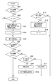
最初のステップS01では、濃度検知部291によって検知された粒子濃度が、閾値TH2以上であるか否かが判定される。閾値TH2とは、粒子低減制御の実行が必要となるような粒子濃度の値として、予め設定されている閾値である。粒子濃度が閾値TH2以上である場合にはステップS02に移行する。
In the first step S01, it is determined whether the particle concentration detected by the concentration detection unit 291 is equal to or higher than the threshold TH2. The threshold TH2 is a threshold set in advance as a value of the particle concentration that requires execution of particle reduction control. When the particle concentration is equal to or higher than the threshold TH2, the process proceeds to step S02.
ステップS02では、フラグFLの値が0であるか否かが判定される。フラグFLとは、粒子低減制御が実行中の時には1が設定され、それ以外の時には0が設定される変数である。フラグFLの値が0である場合、すなわち、粒子低減制御がこれから開始される場合には、ステップS03に移行する。フラグFLの値が1である場合、すなわち、粒子低減制御が既に実行中である場合には、後述のステップS05に移行する。
In step S02, it is determined whether the value of the flag FL is 0 or not. The flag FL is a variable that is set to 1 when particle reduction control is being performed, and is set to 0 otherwise. If the value of the flag FL is 0, that is, if particle reduction control is to be started, the process proceeds to step S03. If the value of the flag FL is 1, that is, if the particle reduction control is already being executed, the process proceeds to step S05 described later.
ステップS03では、現時点における内外気切り換えドア230の開度、及び現時点におけるブロア250の回転数がそれぞれ取得され、これらが記憶部130に記憶される。
In step S03, the opening degree of the inside / outside air switching door 230 at the present time and the rotation speed of the blower 250 at the present time are acquired, respectively, and these are stored in the storage unit 130.
ステップS03に続くステップS04では、フラグFLの値に1が設定される。ステップS04に続くステップS05では、先に述べた粒子低減制御を開始させるための処理が行われる。ここでは、ブロア250の回転数を、それまでの回転数よりも大きくするような処理が行われる。また、内外気切り換えドア230の開度を変更する処理も行われる。本実施形態では、粒子低減制御として複数種類の制御が並行して実行される。それぞれの制御の具体的な内容については後に説明する。
In step S04 following step S03, 1 is set to the value of the flag FL. In step S05 following step S04, the above-described processing for starting the particle reduction control is performed. Here, processing is performed such that the number of rotations of the blower 250 is made larger than the number of rotations up to that point. Further, processing for changing the opening degree of the inside / outside air switching door 230 is also performed. In the present embodiment, a plurality of types of control are executed in parallel as particle reduction control. The specific content of each control will be described later.
ステップS05に続くステップS06では、ステップS05の処理が行われてから所定期間が経過したか否かが判定される。所定期間が経過していなければ、図2に示される一連の処理を終了する。所定期間が経過していれば、ステップS07に移行する。
In step S06 following step S05, it is determined whether a predetermined period has elapsed since the process of step S05 is performed. If the predetermined time period has not elapsed, the series of processes shown in FIG. 2 are ended. If the predetermined period has elapsed, the process proceeds to step S07.
ステップS07では、濃度検知部291によって検知された粒子濃度が、閾値TH1以下であるか否かが判定される。閾値TH1とは、粒子低減制御が正常に効果を発揮している状態で上記の所定期間が経過すれば、十分に下回ると想定される粒子濃度の値として予め設定されている閾値である。閾値TH1の値は、上記の閾値TH2の値よりも小さく、且つ後述の閾値TH0の値よりも大きい。
In step S07, it is determined whether the particle concentration detected by the concentration detection unit 291 is equal to or less than the threshold TH1. The threshold value TH1 is a threshold value which is preset as a value of particle concentration which is assumed to be sufficiently lower if the above-mentioned predetermined period elapses in a state where the particle reduction control is normally effective. The value of the threshold TH1 is smaller than the value of the above-mentioned threshold TH2 and larger than the value of the below-mentioned threshold TH0.
ステップS07において、粒子濃度が閾値TH1以下である場合には、粒子低減制御が正常に効果を発揮しているということである。このため、この場合には特段の処理を行うことなく、図2に示される一連の処理を終了する。
In step S07, when the particle concentration is equal to or less than the threshold value TH1, it means that the particle reduction control is normally effective. Therefore, in this case, the series of processes shown in FIG. 2 are ended without performing any special process.
ステップS07において、粒子濃度が閾値TH1を超えている場合には、ステップS08に移行する。ステップS08では、濃度検知部291によって検知された粒子濃度が、閾値TH3以上であるか否かが判定される。閾値TH3とは、車室内で喫煙が行われた場合において検知されると思われる最低限の粒子濃度の値として、予め設定された閾値である。図6に示されるように、閾値TH3の値は閾値TH2の値よりも大きい。
If the particle concentration exceeds the threshold TH1 in step S07, the process proceeds to step S08. In step S08, it is determined whether the particle concentration detected by the concentration detection unit 291 is equal to or higher than the threshold TH3. The threshold TH3 is a threshold set in advance as a value of the minimum particle concentration which is considered to be detected when smoking is performed in the vehicle compartment. As shown in FIG. 6, the value of the threshold TH3 is larger than the value of the threshold TH2.
ステップS08において、粒子濃度が閾値TH3未満である場合には、ステップS09に移行する。ステップS09に移行したということは、車室内で喫煙が行われていない状況において粒子低減制御が行われたにも拘らず、その効果が十分には発揮されなかったということである。そこで、ステップS09では、内気のみが導入され外気は導入されない状態となるように、内外気切り換えドア230の開度が制御部120により調整される。これにより、車両の外からの粒子の流入が防止される。
If the particle concentration is less than the threshold TH3 in step S08, the process proceeds to step S09. Shifting to step S09 means that although the particle reduction control was performed in a situation where smoking was not performed in the vehicle interior, the effect was not sufficiently exhibited. Therefore, in step S09, the opening degree of the inside / outside air switching door 230 is adjusted by the control unit 120 so that only inside air is introduced and outside air is not introduced. This prevents the inflow of particles from the outside of the vehicle.
ステップS09に続くステップS10では、ブロア250の回転数を増加させる処理が制御部120により行われる。これにより、フィルタ240を通過する空気の流量が更に増加し、フィルタ240において単位時間あたりに捕集される粒子の数が大きくなる。
In step S10 following step S09, the control unit 120 performs a process of increasing the rotational speed of the blower 250. As a result, the flow rate of air passing through the filter 240 is further increased, and the number of particles collected per unit time in the filter 240 is increased.
以上のようなステップS09及びステップS10の処理が行われることにより、粒子低減制御がより効率的に行われるようになる。このため、以降においては粒子濃度がより速く低下することが期待される。
By performing the processes of step S09 and step S10 as described above, particle reduction control can be performed more efficiently. For this reason, it is expected that the particle concentration will decrease more rapidly thereafter.
ステップS08において、粒子濃度が閾値TH3以上であった場合には、ステップS11に移行する。ステップS11に移行した場合には、車室内で喫煙が行われている可能性が高い。この場合、粒子低減制御を継続したとしても、フィルタ240での捕集のみによって車室内の粒子濃度を低下させることは難しい。このため、ステップS11では、外気のみが導入され内気は導入されない状態となるように、内外気切り換えドア230の開度が制御部120により調整される。これにより、車室内の粒子が空気と共に車外に排出されるようになるので、車室内の粒子濃度をある程度低下させることができる。
In step S08, when the particle concentration is equal to or higher than the threshold TH3, the process proceeds to step S11. When the process proceeds to step S11, there is a high possibility that smoking is being performed in the vehicle compartment. In this case, even if the particle reduction control is continued, it is difficult to reduce the particle concentration in the vehicle interior only by the collection with the filter 240. For this reason, in step S11, the opening degree of the inside / outside air switching door 230 is adjusted by the control unit 120 so that only outside air is introduced and inside air is not introduced. As a result, the particles in the passenger compartment can be discharged to the outside of the vehicle together with the air, so that the particle concentration in the passenger compartment can be reduced to some extent.
このように、本実施形態における制御部120は、粒子濃度が所定の上限値(閾値TH3)を超えている場合には、外気導入部220から導入される空気の流量が最大となるように内外気切り換えドア230を制御する。これにより、フィルタ240での捕集のみによって車室内の粒子濃度を低下させることが難しい状況で、外気の導入量が小さいまま粒子低減制御が継続されてしまうような事態が防止される。
As described above, when the particle concentration exceeds the predetermined upper limit value (the threshold TH3), the control unit 120 in the present embodiment performs the inside and outside so that the flow rate of air introduced from the outside air introducing unit 220 becomes maximum. The air switching door 230 is controlled. As a result, in a situation where it is difficult to reduce the concentration of particles in the vehicle interior only by the collection by the filter 240, it is possible to prevent the situation where particle reduction control is continued while the amount of outside air introduced is small.
尚、ステップS07において粒子濃度が閾値TH1を超えていた場合には、本実施形態では上記のようにステップS08に移行し、必要に応じて内気の導入量を増加させる処理(ステップS09)が行われる。このような態様に換えて、ステップS07において粒子濃度が閾値TH1を超えていた場合には、常にステップS11の処理が行われることとしてもよい。
If the particle concentration exceeds the threshold value TH1 in step S07, the process proceeds to step S08 in the present embodiment as described above, and the process of increasing the introduction amount of inside air as necessary (step S09) is performed. It will be. Instead of such a mode, when the particle concentration exceeds the threshold TH1 in step S07, the process of step S11 may be performed at all times.
すなわち、粒子低減制御が開始されてから所定期間が経過しても、粒子濃度が所定の閾値(TH1)を下回らない場合には、制御部120が、外気導入部220から導入される空気の流量が最大となるように内外気切り換えドア230を制御することとしてもよい。このような制御によれば、粒子濃度を迅速に低下させることが難しい状況においては、粒子濃度を低下させることよりも、窓の曇りを晴らすことを優先させることが可能となる。この場合、以降における粒子低減制御の実行を中断し、その旨を乗員に報知することとしてもよい。
That is, if the particle concentration does not fall below the predetermined threshold (TH1) even if a predetermined period has elapsed since the start of the particle reduction control, the control unit 120 controls the flow rate of air introduced from the outside air introducing unit 220. The inside / outside air switching door 230 may be controlled such that According to such control, in a situation where it is difficult to reduce the particle concentration quickly, it is possible to give priority to clearing the window rather than reducing the particle concentration. In this case, the execution of the particle reduction control thereafter may be interrupted to notify the occupant of that effect.
ステップS01において、粒子濃度が閾値TH2未満であった場合には、ステップS12に移行する。ステップS12では、濃度検知部291によって検知された粒子濃度が、閾値TH0以下であるか否かが判定される。閾値TH0とは、粒子低減制御を終了(中断)させる際の粒子濃度として予め設定された閾値である。図6に示されるように、閾値TH0の値は閾値TH2の値よりも低い。
If the particle concentration is less than the threshold TH2 in step S01, the process proceeds to step S12. In step S12, it is determined whether the particle concentration detected by the concentration detection unit 291 is equal to or less than the threshold TH0. The threshold TH0 is a threshold set in advance as the particle concentration at the time of ending (suspending) the particle reduction control. As shown in FIG. 6, the value of the threshold TH0 is lower than the value of the threshold TH2.
ステップS12において、粒子濃度が閾値TH0を越えていた場合には、特段の処理を行うことなく図2に示される一連の処理を終了する。このとき、粒子低減制御が実行中であった場合には、引き続き粒子低減制御が継続される。
In step S12, when the particle concentration exceeds the threshold TH0, the series of processes shown in FIG. 2 are ended without performing any special process. At this time, when the particle reduction control is being performed, the particle reduction control is continued.
ステップS12において、粒子濃度が閾値TH0以下であった場合には、ステップS13に移行する。ステップS13に移行したということは、粒子低減制御によって車室内の粒子濃度が十分に下がったということである。そこで、ステップS13では、内外気切り換えドア230の開度、及びブロア250の回転数のそれぞれが、ステップS03において記憶部130に記憶されていた値に戻される。これにより、粒子低減制御を一旦終了し、通常通りの空調制御を行いながら待機している状態となる。
In step S12, when the particle concentration is equal to or less than the threshold TH0, the process proceeds to step S13. Moving to step S13 means that the particle concentration in the vehicle interior is sufficiently reduced by the particle reduction control. Therefore, in step S13, the degree of opening of the inside / outside air switching door 230 and the rotational speed of the blower 250 are returned to the values stored in the storage unit 130 in step S03. As a result, the particle reduction control is temporarily ended, and the air conditioning control as usual is performed and in a standby state.
ステップS13に続くステップS14では、フラグFLの値が0に戻される。その後、図2に示される一連の処理を終了する。以降の期間において、濃度検知部291によって検知された粒子濃度が再び閾値TH2以上になると、ステップS01乃至S04を経てステップS05に移行し、粒子低減制御が再開されることとなる。
In step S14 following step S13, the value of the flag FL is returned to 0. Thereafter, the series of processes shown in FIG. 2 are ended. In the subsequent period, when the particle concentration detected by the concentration detection unit 291 again becomes equal to or higher than the threshold TH2, the process proceeds to step S05 via steps S01 to S04, and the particle reduction control is restarted.
ステップS05で開始される粒子低減制御の具体的な内容について説明する。既に述べたように、本実施形態では、粒子低減制御として複数種類の制御が並行して実行される。そのうちの一つの制御(以下では「粒子低減制御1」とも表記する)について、図3を参照しながら説明する。
Specific contents of the particle reduction control started in step S05 will be described. As described above, in the present embodiment, a plurality of types of control are executed in parallel as particle reduction control. One of the controls (hereinafter also referred to as “particle reduction control 1”) will be described with reference to FIG.
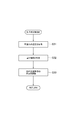
粒子低減制御1の最初のステップS21では、濃度検知部291により車室内の粒子濃度が取得される。ステップS21に続くステップS22では、粒子濃度に基づいて内外気切り換えドア230の開度を調整する処理が行われる。具体的には、制御部120は、粒子濃度が高いときには、外気導入部220から導入される空気の流量が低減するように、内外気切り換えドア230の開度を調整する。これにより、外気導入部220から流入する粒子の量が必要に応じて低減されるので、車室内の粒子濃度が高くなり過ぎてしまうことが防止される。
In the first step S21 of the particle reduction control 1, the concentration detection unit 291 acquires the particle concentration in the vehicle interior. In step S22 following step S21, processing is performed to adjust the opening degree of the inside / outside air switching door 230 based on the particle concentration. Specifically, when the particle concentration is high, the control unit 120 adjusts the opening degree of the inside / outside air switching door 230 so that the flow rate of air introduced from the outside air introducing unit 220 is reduced. As a result, the amount of particles flowing in from the outside air introducing unit 220 is reduced as necessary, so that the concentration of particles in the vehicle compartment is prevented from becoming too high.
粒子濃度と内外気切り換えドア230の開度との対応関係は、予めマップとして記憶部130に記憶されている。例えば、粒子濃度が高くなるほど、外気導入部220から導入される空気の流量が小さくなるように、上記マップが設定されていればよい。
The correspondence between the particle concentration and the opening degree of the inside / outside air switching door 230 is stored in advance in the storage unit 130 as a map. For example, the map may be set such that the flow rate of air introduced from the outside air introducing unit 220 decreases as the particle concentration increases.
本実施形態では上記のように、粒子低減制御の実行中においては内気のみが導入されるのではなく、外気も導入されることとした上で、導入される外気の流量が制御部120によって調整される。これにより、車室内の湿度や二酸化炭素濃度が高くなり過ぎることを防止することができる。その結果、車室内における粒子濃度を低減しながらも、車両の窓において曇りが発生してしまうこと等を防止することが可能となっている。
In the present embodiment, as described above, not only inside air is introduced during execution of the particle reduction control, but outside air is also introduced, and the flow rate of outside air introduced is adjusted by the control unit 120. Be done. This can prevent the humidity and the carbon dioxide concentration in the vehicle compartment from becoming too high. As a result, it is possible to prevent fogging or the like on the window of the vehicle while reducing the particle concentration in the vehicle interior.
粒子低減制御として実行されるもう一つの制御(以下では「粒子低減制御2」とも表記する)について、図4を参照しながら説明する。
Another control executed as particle reduction control (hereinafter also referred to as “particle reduction control 2”) will be described with reference to FIG.
粒子低減制御2の最初のステップS31では、湿度センサ141により車室内の湿度が取得される。ステップS31に続くステップS32では、曇り判定部110によって曇り指標が判定される。既に述べたように、本実施形態では、車室内の湿度の値がそのまま上曇り指標として用いられる。
In the first step S31 of the particle reduction control 2, the humidity sensor 141 acquires the humidity in the vehicle interior. In step S32 following step S31, the fogging determination unit 110 determines the fogging index. As described above, in the present embodiment, the value of the humidity inside the vehicle compartment is used as it is as the upper fog index.
ステップS32に続くステップS33では、曇り指標に基づいて内外気切り換えドア230の開度を調整する処理が行われる。具体的には、制御部120は、曇り指標が大きいとき(つまり窓の曇りが生じやすいとき)には、外気導入部220から導入される空気の流量が増加するように、内外気切り換えドア230の開度を調整する。これにより、外部から低湿の空気が車室内に導入されるので、粒子低減制御の実行中において窓の曇りが発生することをより確実に防止することができる。曇り指標と内外気切り換えドア230の開度との対応関係は、予めマップとして記憶部130に記憶されている。ここでは、外気導入部220から導入される外気の流量が、曇りを防止するための必要最低限の流量となるように、上記マップが設定されていることが好ましい。
In step S33 following step S32, processing is performed to adjust the opening degree of the inside / outside air switching door 230 based on the fogging index. Specifically, when the fog index is large (that is, when fogging of the window is likely to occur), the control unit 120 causes the inside / outside air switching door 230 to increase the flow rate of the air introduced from the outside air introducing unit 220. Adjust the opening of the. As a result, since low-humid air is introduced into the vehicle compartment from the outside, the occurrence of fogging of the window during execution of the particle reduction control can be more reliably prevented. The correspondence between the fog index and the opening degree of the inside / outside air switching door 230 is stored in advance in the storage unit 130 as a map. Here, it is preferable that the above-described map is set such that the flow rate of the outside air introduced from the outside air introducing unit 220 is the minimum flow rate necessary to prevent fogging.
尚、曇り指標としては、本実施形態のように湿度センサ141で測定された湿度がそのまま用いられてもよいのであるが、他の方法で曇り指標を算出することとしてもよい。例えば、車内カメラ142によって取得された乗員の数が多い程、曇り指標が大きく算出されることとしてもよい。また、空調部260のコンプレッサの動作状態、窓の開閉状態、車両外部の気温や湿度などに基づいて、曇り指標が算出又は補正されることとしてもよい。
Although the humidity measured by the humidity sensor 141 may be used as it is as the fogging index as in this embodiment, the fogging index may be calculated by another method. For example, the fog index may be calculated to be larger as the number of occupants acquired by the in-vehicle camera 142 is larger. In addition, the fogging index may be calculated or corrected based on the operating state of the compressor of the air conditioning unit 260, the opening and closing states of the windows, the temperature and humidity outside the vehicle, and the like.
粒子低減制御として実行されるもう一つの制御(以下では「粒子低減制御3」とも表記する)について、図5を参照しながら説明する。
Another control executed as particle reduction control (hereinafter also referred to as “particle reduction control 3”) will be described with reference to FIG.
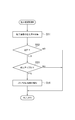
粒子低減制御3の最初のステップS41では、濃度検知部291により車室内の粒子濃度が取得される。ステップS41に続くステップS42では、現在実行されている粒子低減制御3が初回であるか否かが判定される。ここで「初回である」とは、ステップS01からステップS02に最初に移行した時点から、ステップS12からステップS13に移行するまでの期間のことをいう。すなわち、粒子低減制御3が最初に開始されてから終了するまでの期間のことをいう。粒子低減制御3の実行が初回である場合には、ステップS43に移行する。
In the first step S41 of the particle reduction control 3, the concentration detection unit 291 acquires the particle concentration in the vehicle interior. In step S42 following step S41, it is determined whether particle reduction control 3 currently executed is the first time. Here, "it is the first time" means a period from step S01 to step S02 for the first time, and step S12 to step S13. In other words, it refers to a period from the start of the particle reduction control 3 to the end. If the particle reduction control 3 is performed for the first time, the process proceeds to step S43.
ステップS43では、ブロア250の回転数を第1回転数R1とする処理が行われる。尚、この「第1回転数R1」とは固定された回転数ではなく、ステップS41で取得された粒子濃度に応じて設定される回転数である。ここでは、粒子濃度が高い程、第1回転数R1が大きな値に設定される。
In step S43, processing is performed to set the rotation speed of the blower 250 to the first rotation speed R1. The “first rotation number R1” is not a fixed rotation number, but is a rotation number set according to the particle concentration acquired in step S41. Here, as the particle concentration is higher, the first rotation speed R1 is set to a larger value.
このように、本実施形態における制御部120は、粒子濃度が高いときには、ブロア250の回転数を増加させる制御を実行する。このような粒子低減制御3は、本実施形態における「回転数増加制御」に該当するものである。回転数増加制御によって、フィルタ240を通過する空気の流量が増加するので、フィルタ240において単位時間あたりに捕集される粒子の数も大きくなる。その結果、粒子濃度を迅速に低下させることができる。
As described above, when the particle concentration is high, the control unit 120 in the present embodiment executes control to increase the rotational speed of the blower 250. Such particle reduction control 3 corresponds to “rotational speed increase control” in the present embodiment. Since the rotation speed increase control increases the flow rate of air passing through the filter 240, the number of particles collected per unit time in the filter 240 also increases. As a result, particle concentration can be rapidly reduced.
ステップS42において、粒子低減制御3の実行が初回でなかった場合には、ステップS44に移行する。ステップS44では、ブロア250の回転数を第2回転数R2とする処理が行われる。第1回転数R1と同様に、この「第2回転数R2」とは固定された回転数ではなく、ステップS41で取得された粒子濃度に応じて設定される回転数である。ここでは、粒子濃度が高い程、第2回転数R2が大きな値に設定される。ただし、第2回転数R2は、第1回転数R1よりも小さな値に設定される。
If it is determined in step S42 that the particle reduction control 3 has not been executed for the first time, the process proceeds to step S44. In step S44, processing is performed to set the rotation speed of the blower 250 to the second rotation speed R2. Similar to the first rotation number R1, the “second rotation number R2” is not a fixed rotation number, but is a rotation number set according to the particle concentration acquired in step S41. Here, the second rotation speed R2 is set to a larger value as the particle concentration is higher. However, the second rotation speed R2 is set to a value smaller than the first rotation speed R1.
図6(A)に示されるのは、粒子低減制御3が実行されているときにおける、車室内の粒子濃度の時間変化である。図6(B)に示されるのは、粒子低減制御3が実行されているときにおける、ブロア250の回転数の時間変化である。
What is shown in FIG. 6A is the time change of the particle concentration in the passenger compartment when the particle reduction control 3 is being performed. What is shown in FIG. 6 (B) is the time change of the rotation speed of the blower 250 when the particle reduction control 3 is being performed.
図6に示される例では、時刻t1において粒子低減制御の実行が開始されており、ブロア250の回転数が第1回転数R1とされている。時刻t1以降においては、粒子低減制御によって粒子濃度が低下しており、時刻t2において閾値TH0まで低下している。このため、時刻t2の時点で図2のステップS13の処理が行われ、粒子低減制御が一旦終了している。その結果、時刻t2以降では、ブロア250の回転数が当初の回転数R0に戻されている。
In the example shown in FIG. 6, execution of particle reduction control is started at time t1, and the rotation speed of the blower 250 is set to the first rotation speed R1. After time t1, the particle concentration is reduced by the particle reduction control, and is reduced to the threshold TH0 at time t2. Therefore, the process of step S13 of FIG. 2 is performed at time t2, and the particle reduction control is temporarily ended. As a result, after time t2, the rotational speed of the blower 250 is returned to the initial rotational speed R0.
時刻t2以降は、粒子低減制御が行われていないので、車室内の粒子濃度は次第に増加している。その後、時刻t3において粒子濃度が閾値TH2まで上昇すると、再び粒子低減制御が開始される。このときのブロア250の回転数は、第1回転数R1よりも小さな第2回転数R2とされる。
Since the particle reduction control is not performed after time t2, the particle concentration in the vehicle compartment is gradually increasing. Thereafter, when the particle concentration rises to the threshold TH2 at time t3, the particle reduction control is started again. The rotation speed of the blower 250 at this time is set to a second rotation speed R2 smaller than the first rotation speed R1.
以降は、粒子低減制御の終了、再開が繰り返されることにより、車室内の粒子濃度は閾値TH0から閾値TH2までの範囲内で変化する。
Thereafter, the particle concentration in the vehicle compartment changes in the range from the threshold TH0 to the threshold TH2 by repeating termination and restart of the particle reduction control.
このように、粒子低減制御の実行中において、本実施形態の制御部120は、初回における回転数増加制御の実行時には、ブロア250の回転数を第1回転数R1とし、2回目以降における回転数増加制御の実行時には、ブロア250の回転数を、第1回転数R1よりも小さな第2回転数R2とする。
As described above, during execution of the particle reduction control, the control unit 120 of the present embodiment sets the rotation speed of the blower 250 as the first rotation speed R1 at the time of execution of the rotation speed increase control at the first time. At the time of execution of the increase control, the rotation speed of the blower 250 is set to a second rotation speed R2 smaller than the first rotation speed R1.
回転数増加制御の初回実行時においては、車室内の粒子濃度は高くなっている場合が多いと考えられる。このため、上記のようにブロア250の回転数を大きくし、粒子濃度の低減速度を高めた方が好ましい。
At the time of the first execution of the rotation speed increase control, it is considered that the particle concentration in the vehicle interior is often high. For this reason, it is preferable to increase the rotational speed of the blower 250 as described above and to increase the reduction rate of the particle concentration.
一方、回転数増加制御の2回目以降の実行時においては、車室内の粒子濃度は低くなっており、最大でも閾値TH2程度となっている。このため、ブロア250の回転数を大きくする必要性は小さい。本実施形態では、2回目以降の実行時におけるブロア250の回転数を小さくすることにより、ブロア250の動作に伴う車室内の騒音を低減し、乗員に不快な思いをさせてしまうことを防止している。
On the other hand, in the second and subsequent executions of the rotation speed increase control, the particle concentration in the vehicle compartment is low, and at most is about the threshold value TH2. Therefore, the need to increase the rotational speed of the blower 250 is small. In the present embodiment, by reducing the rotational speed of the blower 250 at the second and subsequent executions, the noise in the passenger compartment associated with the operation of the blower 250 is reduced to prevent the occupant from feeling unpleasant. ing.
粒子低減制御として実行されるもう一つの制御(以下では「粒子低減制御4」とも表記する)について、図7を参照しながら説明する。
Another control executed as particle reduction control (hereinafter also referred to as “particle reduction control 4”) will be described with reference to FIG.
粒子低減制御4の最初のステップS51では、濃度検知部291によって測定される粒子濃度の低下率が取得される。この低下率は、例えば、現時点までの一定期間において複数回サンプリングされた測定値、の傾き等に基づいて算出することができる。
In the first step S51 of the particle reduction control 4, the reduction rate of the particle concentration measured by the concentration detection unit 291 is acquired. The reduction rate can be calculated based on, for example, the slope of the measurement values sampled a plurality of times in a certain period up to the present time.
ステップS51に続くステップS52では、現在実行されている粒子低減制御4が初回であるか否かが判定される。ここで「初回である」とは、ステップS01からステップS02に最初に移行した時点から、ステップS12からステップS13に移行するまでの期間のことをいう。すなわち、粒子低減制御4が最初に開始されてから終了するまでの期間のことをいう。粒子低減制御4の実行が初回ではない場合には、図7に示される一連の処理を終了する。粒子低減制御4の実行が初回である場合には、ステップS53に移行する。
In step S52 following step S51, it is determined whether the currently executed particle reduction control 4 is the first process. Here, "it is the first time" means a period from step S01 to step S02 for the first time, and step S12 to step S13. That is, it refers to a period from when the particle reduction control 4 is first started to when it ends. If the particle reduction control 4 is not performed for the first time, the series of processes shown in FIG. 7 are ended. If the particle reduction control 4 is performed for the first time, the process proceeds to step S53.
ステップS53では、ステップS51で取得された低下率が、所定の閾値TR1よりも小さいか否かが判定される。この閾値TH1は、粒子低減制御が正常に効果を発揮している状態において期待される最低限の低下率として、予め設定された閾値である。尚、ここでの低下率とは粒子濃度の減少速度のことであるが、その符号は正であるとする。
In step S53, it is determined whether the reduction rate acquired in step S51 is smaller than a predetermined threshold value TR1. The threshold TH1 is a threshold set in advance as a minimum reduction rate expected in a state where the particle reduction control is normally effective. Here, the rate of decrease is the rate of decrease in particle concentration, but its sign is assumed to be positive.
低下率が閾値TR1以上である場合には、図7に示される一連の処理を終了する。低下率が閾値TR1よりも小さい場合にはステップS54に移行する。
If the reduction rate is equal to or higher than the threshold value TR1, the series of processes shown in FIG. If the decrease rate is smaller than the threshold value TR1, the process proceeds to step S54.
ステップS54に移行したということは、粒子低減制御の効果が十分ではなく、粒子濃度の減少速度が小さいということである。そこで、ステップS54では、ブロア250の回転数を増加させる処理が制御部120により行われる。これにより、フィルタ240を通過する空気の流量が更に増加し、フィルタ240において単位時間あたりに捕集される粒子の数が大きくなる。
Moving to step S54 means that the effect of the particle reduction control is not sufficient, and the decrease rate of the particle concentration is small. Therefore, in step S54, the control unit 120 performs a process of increasing the rotational speed of the blower 250. As a result, the flow rate of air passing through the filter 240 is further increased, and the number of particles collected per unit time in the filter 240 is increased.
以上のような処理が行われることにより、粒子低減制御の効果が何らかの原因で小さくなっている場合でも、粒子濃度の低減がより効率的に行われるようになる。このため、以降においては粒子濃度がより速く低下することが期待される。
By performing the processing as described above, even when the effect of the particle reduction control is reduced for some reason, the particle concentration can be reduced more efficiently. For this reason, it is expected that the particle concentration will decrease more rapidly thereafter.
以上、具体例を参照しつつ本実施形態について説明した。しかし、本開示はこれらの具体例に限定されるものではない。これら具体例に、当業者が適宜設計変更を加えたものも、本開示の特徴を備えている限り、本開示の範囲に包含される。前述した各具体例が備える各要素およびその配置、条件、形状などは、例示したものに限定されるわけではなく適宜変更することができる。前述した各具体例が備える各要素は、技術的な矛盾が生じない限り、適宜組み合わせを変えることができる。
The present embodiment has been described above with reference to the specific example. However, the present disclosure is not limited to these specific examples. Those appropriately modified in design by those skilled in the art are also included in the scope of the present disclosure as long as the features of the present disclosure are included. The elements included in the above-described specific examples, and the arrangement, conditions, and shapes thereof are not limited to those illustrated, but can be appropriately modified. The elements included in the above-described specific examples can be appropriately changed in combination as long as no technical contradiction arises.
Claims (10)
- 車両に搭載される空調装置(10)であって、
前記車両の車室内に吹き出される空気の温度調整を行う空調部(260)と、
前記空調部に供給される空気を前記車両の外部から導入するための外気導入部(220)と、
前記空調部に供給される空気を前記車室内から導入するための内気導入部(210)と、
前記外気導入部及び前記内気導入部のそれぞれから導入される空気の量を調整する内外気調整部(230)と、
前記空調部に供給される空気から粒子を除去するフィルタ(240)と、
前記フィルタ及び前記空調部を通るように空気を送り出すブロア(250)と、
前記内外気調整部及び前記ブロアのそれぞれの動作を制御する制御部(120)と、を備え、
前記制御部は、
前記フィルタを通過する空気の流量を増加させる制御、である粒子低減制御を実行しているときに、前記外気導入部から導入される空気の流量を調整するように構成されている空調装置。 An air conditioner (10) mounted on a vehicle,
An air conditioning unit (260) for adjusting the temperature of the air blown out into the cabin of the vehicle;
An outside air introducing unit (220) for introducing air supplied to the air conditioning unit from the outside of the vehicle;
A room air introducing unit (210) for introducing air supplied to the air conditioning unit from the vehicle compartment;
An inside / outside air adjustment unit (230) for adjusting the amount of air introduced from each of the outside air introduction unit and the inside air introduction unit;
A filter (240) for removing particles from the air supplied to the air conditioning unit;
A blower (250) for delivering air through the filter and the air conditioning unit;
A control unit (120) for controlling the operation of the inside / outside air adjustment unit and the blower;
The control unit
An air conditioner configured to adjust the flow rate of air introduced from the outside air introduction unit when performing particle reduction control, which is control to increase the flow rate of air passing through the filter. - 前記車室内の空気における粒子濃度を検知する濃度検知部(291)を更に備える、請求項1に記載の空調装置。 The air conditioner according to claim 1, further comprising a concentration detection unit (291) that detects a concentration of particles in air in the vehicle compartment.
- 前記粒子低減制御の実行中において、前記制御部は、
前記粒子濃度が高いときには、前記外気導入部から導入される空気の流量を低減させる、請求項2に記載の空調装置。 During execution of the particle reduction control, the control unit
The air conditioner according to claim 2, wherein when the particle concentration is high, the flow rate of air introduced from the outside air introduction unit is reduced. - 前記車両に設けられた窓における曇りの生じやすさを示す曇り指標、を判定する曇り判定部(110)を更に備え、
前記粒子低減制御の実行中において、前記制御部は、
前記曇り指標が大きいときには、前記外気導入部から導入される空気の流量を増加させる、請求項1に記載の空調装置。 The vehicle further comprises a fogging determination unit (110) that determines a fogging index indicating the likelihood of fogging on a window provided in the vehicle.
During execution of the particle reduction control, the control unit
The air conditioner according to claim 1, wherein when the fogging index is large, the flow rate of air introduced from the outside air introducing unit is increased. - 前記曇り判定部は、前記車室内における湿度を前記曇り指標として用いる、請求項4に記載の空調装置。 The air conditioner according to claim 4, wherein the fogging determination unit uses humidity in the vehicle cabin as the fogging index.
- 前記制御部は、前記粒子濃度が高いときには、前記ブロアの回転数を増加させる制御、である回転数増加制御を実行する、請求項2に記載の空調装置。 The air conditioner according to claim 2, wherein the control unit executes rotation number increase control, which is control for increasing the rotation number of the blower when the particle concentration is high.
- 前記粒子低減制御の実行中において、前記制御部は、
初回における前記回転数増加制御の実行時には、前記ブロアの回転数を第1回転数とし、
2回目以降における前記回転数増加制御の実行時には、前記ブロアの回転数を、前記第1回転数よりも小さな第2回転数とする、請求項6に記載の空調装置。 During execution of the particle reduction control, the control unit
At the time of execution of the rotation speed increasing control at the first time, the rotation speed of the blower is taken as a first rotation speed,
The air conditioner according to claim 6, wherein when the rotation number increase control is executed for the second time and thereafter, the rotation number of the blower is set to a second rotation number smaller than the first rotation number. - 前記制御部は、
前記回転数増加制御の実行中における前記粒子濃度の低下率、が所定値よりも低い場合には、前記ブロアの回転数を更に増加させる、請求項6に記載の空調装置。 The control unit
The air conditioner according to claim 6, wherein when the decrease rate of the particle concentration during execution of the rotation speed increase control is lower than a predetermined value, the rotation speed of the blower is further increased. - 前記制御部は、
前記粒子低減制御が開始されてから所定期間が経過しても、前記粒子濃度が所定の閾値を下回らない場合には、前記外気導入部から導入される空気の流量が最大となるように前記内外気調整部を制御する、請求項2に記載の空調装置。 The control unit
If the particle concentration does not fall below a predetermined threshold even after a predetermined period of time has elapsed since the start of the particle reduction control, the inside and outside of the air are introduced such that the flow rate of air introduced from the outside air introduction portion becomes maximum. The air conditioner according to claim 2, which controls the air adjustment unit. - 前記制御部は、
前記粒子濃度が所定の上限値を超えている場合には、前記外気導入部から導入される空気の流量が最大となるように前記内外気調整部を制御する、請求項2に記載の空調装置。 The control unit
The air conditioner according to claim 2, wherein when the particle concentration exceeds a predetermined upper limit value, the inside / outside air adjustment unit is controlled to maximize the flow rate of air introduced from the outside air introduction unit. .
Priority Applications (1)
| Application Number | Priority Date | Filing Date | Title |
|---|---|---|---|
| CN201880048896.7A CN110997374B (en) | 2017-07-28 | 2018-06-15 | Air conditioner |
Applications Claiming Priority (2)
| Application Number | Priority Date | Filing Date | Title |
|---|---|---|---|
| JP2017146621A JP6798440B2 (en) | 2017-07-28 | 2017-07-28 | Air conditioner |
| JP2017-146621 | 2017-07-28 |
Publications (1)
| Publication Number | Publication Date |
|---|---|
| WO2019021681A1 true WO2019021681A1 (en) | 2019-01-31 |
Family
ID=65041371
Family Applications (1)
| Application Number | Title | Priority Date | Filing Date |
|---|---|---|---|
| PCT/JP2018/023011 WO2019021681A1 (en) | 2017-07-28 | 2018-06-15 | Air conditioning device |
Country Status (3)
| Country | Link |
|---|---|
| JP (1) | JP6798440B2 (en) |
| CN (1) | CN110997374B (en) |
| WO (1) | WO2019021681A1 (en) |
Families Citing this family (2)
| Publication number | Priority date | Publication date | Assignee | Title |
|---|---|---|---|---|
| JP7363405B2 (en) | 2019-11-20 | 2023-10-18 | トヨタ自動車株式会社 | Vehicle air conditioner |
| CN112124047A (en) * | 2020-09-09 | 2020-12-25 | 上海仙塔智能科技有限公司 | Air purifier control system and air purifier |
Citations (7)
| Publication number | Priority date | Publication date | Assignee | Title |
|---|---|---|---|---|
| JPH08175161A (en) * | 1994-12-26 | 1996-07-09 | Calsonic Corp | Vehicular air conditioner and air conditioning method for vehicle |
| JP2003326938A (en) * | 2002-05-15 | 2003-11-19 | Denso Corp | Air-conditioning defogging control device for vehicle |
| JP2006103451A (en) * | 2004-10-04 | 2006-04-20 | Denso Corp | Air-conditioner for vehicle |
| JP2006234287A (en) * | 2005-02-25 | 2006-09-07 | Sharp Corp | Air-conditioner control device |
| JP2010166865A (en) * | 2009-01-23 | 2010-08-05 | Iseki & Co Ltd | Combine harvester |
| JP2015214272A (en) * | 2014-05-12 | 2015-12-03 | 株式会社デンソー | Air conditioning device for vehicle |
| JP2016030566A (en) * | 2014-07-30 | 2016-03-07 | 株式会社日本クライメイトシステムズ | Air conditioning device for vehicle |
Family Cites Families (2)
| Publication number | Priority date | Publication date | Assignee | Title |
|---|---|---|---|---|
| JP2003080926A (en) * | 2001-09-13 | 2003-03-19 | Denso Corp | Vehicular air conditioner |
| JP4311270B2 (en) * | 2004-04-21 | 2009-08-12 | 株式会社デンソー | Air conditioner for vehicles |
-
2017
- 2017-07-28 JP JP2017146621A patent/JP6798440B2/en active Active
-
2018
- 2018-06-15 WO PCT/JP2018/023011 patent/WO2019021681A1/en active Application Filing
- 2018-06-15 CN CN201880048896.7A patent/CN110997374B/en active Active
Patent Citations (7)
| Publication number | Priority date | Publication date | Assignee | Title |
|---|---|---|---|---|
| JPH08175161A (en) * | 1994-12-26 | 1996-07-09 | Calsonic Corp | Vehicular air conditioner and air conditioning method for vehicle |
| JP2003326938A (en) * | 2002-05-15 | 2003-11-19 | Denso Corp | Air-conditioning defogging control device for vehicle |
| JP2006103451A (en) * | 2004-10-04 | 2006-04-20 | Denso Corp | Air-conditioner for vehicle |
| JP2006234287A (en) * | 2005-02-25 | 2006-09-07 | Sharp Corp | Air-conditioner control device |
| JP2010166865A (en) * | 2009-01-23 | 2010-08-05 | Iseki & Co Ltd | Combine harvester |
| JP2015214272A (en) * | 2014-05-12 | 2015-12-03 | 株式会社デンソー | Air conditioning device for vehicle |
| JP2016030566A (en) * | 2014-07-30 | 2016-03-07 | 株式会社日本クライメイトシステムズ | Air conditioning device for vehicle |
Also Published As
| Publication number | Publication date |
|---|---|
| JP2019026040A (en) | 2019-02-21 |
| CN110997374B (en) | 2023-04-07 |
| CN110997374A (en) | 2020-04-10 |
| JP6798440B2 (en) | 2020-12-09 |
Similar Documents
| Publication | Publication Date | Title |
|---|---|---|
| US11648818B2 (en) | Air-conditioning system | |
| JP4311270B2 (en) | Air conditioner for vehicles | |
| JP6477652B2 (en) | Air conditioner for vehicles | |
| JP2006001310A (en) | Vehicular inside/outside air change control device | |
| JP2018197095A5 (en) | ||
| WO2018135361A1 (en) | Vehicle air conditioning apparatus | |
| WO2019021681A1 (en) | Air conditioning device | |
| JP2018114948A5 (en) | ||
| JP2018177034A (en) | Air conditioning control device | |
| WO2018116683A1 (en) | Air-conditioning device for vehicle | |
| JP4403942B2 (en) | Air conditioner for vehicles | |
| JP5101999B2 (en) | Air conditioning control device for vehicles | |
| JP6631487B2 (en) | Vehicle air conditioner | |
| JP2007131232A (en) | Air-conditioning control device for vehicle | |
| WO2019008946A1 (en) | Vehicle air conditioning device | |
| JP2006103452A (en) | Air-conditioner for vehicle | |
| CN110997372B (en) | Vehicle notification device | |
| JP2002137630A (en) | Auto air conditioner control device for vehicle | |
| JP7259325B2 (en) | vehicle air conditioner | |
| JP2019026040A5 (en) | ||
| WO2017082074A1 (en) | Air conditioning device for vehicle | |
| JP4706774B2 (en) | Air conditioner for vehicles | |
| CN108473023B (en) | Air conditioner for vehicle | |
| KR20170022340A (en) | Vehicle air conditioning device and method for preventing exhaust gas inflow in vehicle | |
| JP2019038324A (en) | Vehicular air conditioner |
Legal Events
| Date | Code | Title | Description |
|---|---|---|---|
| 121 | Ep: the epo has been informed by wipo that ep was designated in this application |
Ref document number: 18838359 Country of ref document: EP Kind code of ref document: A1 |
|
| NENP | Non-entry into the national phase |
Ref country code: DE |
|
| 122 | Ep: pct application non-entry in european phase |
Ref document number: 18838359 Country of ref document: EP Kind code of ref document: A1 |