WO2019017229A1 - ガス発生器 - Google Patents
ガス発生器 Download PDFInfo
- Publication number
- WO2019017229A1 WO2019017229A1 PCT/JP2018/025931 JP2018025931W WO2019017229A1 WO 2019017229 A1 WO2019017229 A1 WO 2019017229A1 JP 2018025931 W JP2018025931 W JP 2018025931W WO 2019017229 A1 WO2019017229 A1 WO 2019017229A1
- Authority
- WO
- WIPO (PCT)
- Prior art keywords
- igniter
- combustion
- cup
- header
- housing
- Prior art date
- Legal status (The legal status is an assumption and is not a legal conclusion. Google has not performed a legal analysis and makes no representation as to the accuracy of the status listed.)
- Ceased
Links
Images





Classifications
-
- B—PERFORMING OPERATIONS; TRANSPORTING
- B60—VEHICLES IN GENERAL
- B60R—VEHICLES, VEHICLE FITTINGS, OR VEHICLE PARTS, NOT OTHERWISE PROVIDED FOR
- B60R21/00—Arrangements or fittings on vehicles for protecting or preventing injuries to occupants or pedestrians in case of accidents or other traffic risks
- B60R21/02—Occupant safety arrangements or fittings, e.g. crash pads
- B60R21/16—Inflatable occupant restraints or confinements designed to inflate upon impact or impending impact, e.g. air bags
- B60R21/26—Inflatable occupant restraints or confinements designed to inflate upon impact or impending impact, e.g. air bags characterised by the inflation fluid source or means to control inflation fluid flow
- B60R21/264—Inflatable occupant restraints or confinements designed to inflate upon impact or impending impact, e.g. air bags characterised by the inflation fluid source or means to control inflation fluid flow using instantaneous generation of gas, e.g. pyrotechnic
- B60R21/2644—Inflatable occupant restraints or confinements designed to inflate upon impact or impending impact, e.g. air bags characterised by the inflation fluid source or means to control inflation fluid flow using instantaneous generation of gas, e.g. pyrotechnic using only solid reacting substances, e.g. pellets, powder
-
- B—PERFORMING OPERATIONS; TRANSPORTING
- B60—VEHICLES IN GENERAL
- B60R—VEHICLES, VEHICLE FITTINGS, OR VEHICLE PARTS, NOT OTHERWISE PROVIDED FOR
- B60R21/00—Arrangements or fittings on vehicles for protecting or preventing injuries to occupants or pedestrians in case of accidents or other traffic risks
- B60R21/02—Occupant safety arrangements or fittings, e.g. crash pads
- B60R21/16—Inflatable occupant restraints or confinements designed to inflate upon impact or impending impact, e.g. air bags
- B60R21/26—Inflatable occupant restraints or confinements designed to inflate upon impact or impending impact, e.g. air bags characterised by the inflation fluid source or means to control inflation fluid flow
- B60R21/263—Inflatable occupant restraints or confinements designed to inflate upon impact or impending impact, e.g. air bags characterised by the inflation fluid source or means to control inflation fluid flow using a variable source, e.g. plural stage or controlled output
-
- B—PERFORMING OPERATIONS; TRANSPORTING
- B01—PHYSICAL OR CHEMICAL PROCESSES OR APPARATUS IN GENERAL
- B01J—CHEMICAL OR PHYSICAL PROCESSES, e.g. CATALYSIS OR COLLOID CHEMISTRY; THEIR RELEVANT APPARATUS
- B01J7/00—Apparatus for generating gases
-
- B—PERFORMING OPERATIONS; TRANSPORTING
- B60—VEHICLES IN GENERAL
- B60R—VEHICLES, VEHICLE FITTINGS, OR VEHICLE PARTS, NOT OTHERWISE PROVIDED FOR
- B60R21/00—Arrangements or fittings on vehicles for protecting or preventing injuries to occupants or pedestrians in case of accidents or other traffic risks
- B60R21/02—Occupant safety arrangements or fittings, e.g. crash pads
- B60R21/16—Inflatable occupant restraints or confinements designed to inflate upon impact or impending impact, e.g. air bags
- B60R21/26—Inflatable occupant restraints or confinements designed to inflate upon impact or impending impact, e.g. air bags characterised by the inflation fluid source or means to control inflation fluid flow
- B60R21/264—Inflatable occupant restraints or confinements designed to inflate upon impact or impending impact, e.g. air bags characterised by the inflation fluid source or means to control inflation fluid flow using instantaneous generation of gas, e.g. pyrotechnic
-
- B—PERFORMING OPERATIONS; TRANSPORTING
- B60—VEHICLES IN GENERAL
- B60R—VEHICLES, VEHICLE FITTINGS, OR VEHICLE PARTS, NOT OTHERWISE PROVIDED FOR
- B60R21/00—Arrangements or fittings on vehicles for protecting or preventing injuries to occupants or pedestrians in case of accidents or other traffic risks
- B60R21/02—Occupant safety arrangements or fittings, e.g. crash pads
- B60R21/16—Inflatable occupant restraints or confinements designed to inflate upon impact or impending impact, e.g. air bags
- B60R21/26—Inflatable occupant restraints or confinements designed to inflate upon impact or impending impact, e.g. air bags characterised by the inflation fluid source or means to control inflation fluid flow
- B60R2021/26011—Inflatable occupant restraints or confinements designed to inflate upon impact or impending impact, e.g. air bags characterised by the inflation fluid source or means to control inflation fluid flow using a filter through which the inflation gas passes
-
- B—PERFORMING OPERATIONS; TRANSPORTING
- B60—VEHICLES IN GENERAL
- B60R—VEHICLES, VEHICLE FITTINGS, OR VEHICLE PARTS, NOT OTHERWISE PROVIDED FOR
- B60R21/00—Arrangements or fittings on vehicles for protecting or preventing injuries to occupants or pedestrians in case of accidents or other traffic risks
- B60R21/02—Occupant safety arrangements or fittings, e.g. crash pads
- B60R21/16—Inflatable occupant restraints or confinements designed to inflate upon impact or impending impact, e.g. air bags
- B60R21/26—Inflatable occupant restraints or confinements designed to inflate upon impact or impending impact, e.g. air bags characterised by the inflation fluid source or means to control inflation fluid flow
- B60R2021/26029—Ignitors
-
- B—PERFORMING OPERATIONS; TRANSPORTING
- B60—VEHICLES IN GENERAL
- B60R—VEHICLES, VEHICLE FITTINGS, OR VEHICLE PARTS, NOT OTHERWISE PROVIDED FOR
- B60R21/00—Arrangements or fittings on vehicles for protecting or preventing injuries to occupants or pedestrians in case of accidents or other traffic risks
- B60R21/02—Occupant safety arrangements or fittings, e.g. crash pads
- B60R21/16—Inflatable occupant restraints or confinements designed to inflate upon impact or impending impact, e.g. air bags
- B60R21/26—Inflatable occupant restraints or confinements designed to inflate upon impact or impending impact, e.g. air bags characterised by the inflation fluid source or means to control inflation fluid flow
- B60R2021/26076—Inflatable occupant restraints or confinements designed to inflate upon impact or impending impact, e.g. air bags characterised by the inflation fluid source or means to control inflation fluid flow characterised by casing
-
- B—PERFORMING OPERATIONS; TRANSPORTING
- B60—VEHICLES IN GENERAL
- B60R—VEHICLES, VEHICLE FITTINGS, OR VEHICLE PARTS, NOT OTHERWISE PROVIDED FOR
- B60R21/00—Arrangements or fittings on vehicles for protecting or preventing injuries to occupants or pedestrians in case of accidents or other traffic risks
- B60R21/02—Occupant safety arrangements or fittings, e.g. crash pads
- B60R21/16—Inflatable occupant restraints or confinements designed to inflate upon impact or impending impact, e.g. air bags
- B60R21/26—Inflatable occupant restraints or confinements designed to inflate upon impact or impending impact, e.g. air bags characterised by the inflation fluid source or means to control inflation fluid flow
- B60R21/263—Inflatable occupant restraints or confinements designed to inflate upon impact or impending impact, e.g. air bags characterised by the inflation fluid source or means to control inflation fluid flow using a variable source, e.g. plural stage or controlled output
- B60R2021/2633—Inflatable occupant restraints or confinements designed to inflate upon impact or impending impact, e.g. air bags characterised by the inflation fluid source or means to control inflation fluid flow using a variable source, e.g. plural stage or controlled output with a plurality of inflation levels
-
- B—PERFORMING OPERATIONS; TRANSPORTING
- B60—VEHICLES IN GENERAL
- B60R—VEHICLES, VEHICLE FITTINGS, OR VEHICLE PARTS, NOT OTHERWISE PROVIDED FOR
- B60R21/00—Arrangements or fittings on vehicles for protecting or preventing injuries to occupants or pedestrians in case of accidents or other traffic risks
- B60R21/02—Occupant safety arrangements or fittings, e.g. crash pads
- B60R21/16—Inflatable occupant restraints or confinements designed to inflate upon impact or impending impact, e.g. air bags
- B60R21/26—Inflatable occupant restraints or confinements designed to inflate upon impact or impending impact, e.g. air bags characterised by the inflation fluid source or means to control inflation fluid flow
- B60R21/264—Inflatable occupant restraints or confinements designed to inflate upon impact or impending impact, e.g. air bags characterised by the inflation fluid source or means to control inflation fluid flow using instantaneous generation of gas, e.g. pyrotechnic
- B60R2021/2642—Inflatable occupant restraints or confinements designed to inflate upon impact or impending impact, e.g. air bags characterised by the inflation fluid source or means to control inflation fluid flow using instantaneous generation of gas, e.g. pyrotechnic comprising a plurality of combustion chambers or sub-chambers
-
- B—PERFORMING OPERATIONS; TRANSPORTING
- B60—VEHICLES IN GENERAL
- B60R—VEHICLES, VEHICLE FITTINGS, OR VEHICLE PARTS, NOT OTHERWISE PROVIDED FOR
- B60R21/00—Arrangements or fittings on vehicles for protecting or preventing injuries to occupants or pedestrians in case of accidents or other traffic risks
- B60R21/02—Occupant safety arrangements or fittings, e.g. crash pads
- B60R21/16—Inflatable occupant restraints or confinements designed to inflate upon impact or impending impact, e.g. air bags
- B60R21/26—Inflatable occupant restraints or confinements designed to inflate upon impact or impending impact, e.g. air bags characterised by the inflation fluid source or means to control inflation fluid flow
- B60R21/264—Inflatable occupant restraints or confinements designed to inflate upon impact or impending impact, e.g. air bags characterised by the inflation fluid source or means to control inflation fluid flow using instantaneous generation of gas, e.g. pyrotechnic
- B60R21/2644—Inflatable occupant restraints or confinements designed to inflate upon impact or impending impact, e.g. air bags characterised by the inflation fluid source or means to control inflation fluid flow using instantaneous generation of gas, e.g. pyrotechnic using only solid reacting substances, e.g. pellets, powder
- B60R2021/2648—Inflatable occupant restraints or confinements designed to inflate upon impact or impending impact, e.g. air bags characterised by the inflation fluid source or means to control inflation fluid flow using instantaneous generation of gas, e.g. pyrotechnic using only solid reacting substances, e.g. pellets, powder comprising a plurality of combustion chambers or sub-chambers
-
- B—PERFORMING OPERATIONS; TRANSPORTING
- B60—VEHICLES IN GENERAL
- B60R—VEHICLES, VEHICLE FITTINGS, OR VEHICLE PARTS, NOT OTHERWISE PROVIDED FOR
- B60R21/00—Arrangements or fittings on vehicles for protecting or preventing injuries to occupants or pedestrians in case of accidents or other traffic risks
- B60R21/02—Occupant safety arrangements or fittings, e.g. crash pads
- B60R21/16—Inflatable occupant restraints or confinements designed to inflate upon impact or impending impact, e.g. air bags
- B60R21/26—Inflatable occupant restraints or confinements designed to inflate upon impact or impending impact, e.g. air bags characterised by the inflation fluid source or means to control inflation fluid flow
- B60R21/261—Inflatable occupant restraints or confinements designed to inflate upon impact or impending impact, e.g. air bags characterised by the inflation fluid source or means to control inflation fluid flow with means other than bag structure to diffuse or guide inflation fluid
Definitions
- the present invention relates to a gas generator that burns a gas generating agent to generate a combustion gas by explosive combustion in an igniter.
- a gas generator which burns a gas generating agent by pyrotechnic combustion in an igniter is widely used as a power source for realizing a desired operation of the generated combustion gas.
- a gas generator can be used, for example, as a drive source for deploying an air bag of an air bag device mounted on a vehicle or the like. In such a gas generator, it is necessary to burn the gas generating agent as desired in order to generate the combustion gas as designed.
- the tip of the igniter is covered by the ignition lid, and the ignition agent is burned in the space covered by the ignition lid.
- an ignition hole which ejects a flame by explosives combustion is formed in an ignition lid.
- the ignition hole is formed to eject a flame toward the periphery of the axis of the cylindrical gas generator housing. According to such a configuration, a flame due to explosive combustion is released to the side of the igniter, whereby combustion is initiated for the gas generating agent located around the axis in the gas generator housing. .
- the gas generating agent In order to burn the gas generating agent as desired, it is required to set the discharge direction of the combustion product generated by the explosive combustion to the desired direction. And, in the gas generator of the prior art, it is intended to discharge the combustion products radially to the side of the explosive charge storage space in the igniter.
- the gas generating agent may be arranged not only on the side of the explosive containing space but also on the lower side of the space.
- the prior art comprised so that the combustion product produced by explosive combustion might be discharged
- An object of the present invention is, in view of the above-mentioned problems, to provide a technology capable of suitably burning a gas generating agent disposed around an igniter.
- an igniter included in the gas generator of the present invention can be desorbed from the igniter and moved in a predetermined direction by the action of combustion products generated by the explosive combustion in the igniter.
- the detachment part configured in FIG.
- the combustion product received by the desorption unit is transmitted by the guide unit of the desorption unit.
- the gas generator was configured to point to the side. Such a configuration makes it possible to suitably burn the gas generating agent disposed around the igniter.
- the gas generator of the present invention is an igniter including a storage chamber in which the explosive is stored, and an ignition unit provided in the storage chamber and configured to ignite the explosive, and the igniter A desorbing portion having a pressure receiving surface for receiving combustion products generated by explosives combustion, configured to be able to desorb from the igniter and move in a predetermined direction by the action of the combustion products on the pressure receiving surface.
- a combustion chamber in which the gas generating agent charged outside the storage chamber is burned by the igniter having the desorption portion and the pyrotechnic combustion in the igniter, the igniter being formed so as to surround the igniter A combustion chamber and a restriction unit provided at a predetermined position in the predetermined direction from the igniter disposed in the combustion chamber, and restricting the movement of the detachment unit in the predetermined direction And a restriction unit.
- desorption part is a guide which directs the combustion product received by the said pressure-receiving surface to the said igniter side in the state by which the movement to the said predetermined direction of this detachment
- the above-mentioned igniter is integrated with the igniter prior to the combustion of the explosive and has a detachment part which detaches from the igniter after the combustion of the explosive.
- the combustion products generated by the pyrotechnic combustion act on the pressure receiving surface of the desorption unit.
- the desorption part is detached from the igniter.
- the desorption unit is configured to be movable in a predetermined direction by the action of the combustion product on the pressure receiving surface. Therefore, the desorption part detached from the igniter moves in a predetermined direction from the igniter in the combustion chamber formed to surround the igniter.
- a limiting portion is provided at a predetermined position in a predetermined direction from the igniter. Therefore, the desorption unit moving in the predetermined direction from the igniter in the combustion chamber contacts the limiting unit in the middle of the movement, and the movement is restricted.
- the combustion product reflected by the pressure receiving surface of the desorption unit is guided by the guide unit of the detachment unit to the side of the igniter. It is directed to the combustion chamber.
- the combustion products thus spread in the combustion chamber burn the gas generating agent on the side of the igniter. That is, the combustion of the gas generating agent disposed around the igniter is promoted. Thereby, it becomes possible to preferably burn the gas generating agent disposed around the igniter, thereby suppressing the uneven combustion of the gas generating agent as much as possible, and exhibiting a suitable combustion gas generating capability.
- the igniter is connected to a header to which the ignition part is fixed, a bottom part arranged to face the ignition part, and a periphery of the bottom part
- the cup may further include a peripheral wall portion disposed to surround the ignition portion
- the storage cup may further include a housing cup formed by the peripheral wall portion and the bottom surface portion.
- the desorption portion is the housing cup
- the inner wall surface of the housing cup is the pressure receiving surface
- the peripheral wall portion serves as the guide portion for the combustion product as the header. It may be directed to the side.
- the inner wall surface of the storage cup forming the storage chamber functions as a pressure receiving surface
- the combustion product generated by the explosive combustion can be suitably applied to the pressure receiving surface.
- the storage cup is easily detached from the igniter.
- the peripheral wall portion of the housing cup serves as a guide portion to direct the combustion product received by the pressure receiving surface toward the header of the igniter.
- the gas generating agent disposed around the igniter can be suitably burned.
- the storage cup is in a state before the pyrotechnic combustion in the igniter so that the storage cup can be detached from the header side by the pyrotechnic combustion in the igniter. May be fixed to the header. Then, the gas generator is a peripheral edge on the header side of the storage cup in a state where the movement of the storage cup desorbed in the predetermined direction is limited by the restriction portion by the explosive combustion in the igniter.
- the opening defined in may be expanded in diameter, and the peripheral wall having the expanded opening may be configured to direct the combustion product to the side of the header.
- the combustion product generated by the explosive combustion acts on the pressure receiving surface of the containing cup
- the fixed state between the containing cup and the header can not be maintained.
- the storage cup is detached from the header side and moves in a predetermined direction from the igniter through the combustion chamber. And in the middle of the movement, it contacts a restriction part and the movement is restricted.
- a state in which the opening of the storage cup is expanded is formed. In such a state, the combustion products reflected by the pressure receiving surface of the storage cup are easily directed to a wide range on the side of the header of the combustion chamber by the peripheral wall portion of the storage cup.
- the combustion products released from the storage cup will be led to a wide area on the side of the header of the combustion chamber, whereby the combustion of the gas generating agent disposed around the igniter becomes more extensive. Promoted throughout. That is, it is possible to suitably burn the gas generating agent disposed around the igniter.
- the above-mentioned storage cup may include the 1st weak part which changes so that the diameter of the above-mentioned opening of the storage cup may be expanded by the effect of the above-mentioned combustion product.
- the peripheral wall portion including the first fragile portion is easily deformed in the direction in which the opening of the accommodation cup is expanded. This makes it easier to direct the products of combustion to a wider area on the header of the combustion chamber. As a result, the combustion of the gas generating agent disposed around the igniter is promoted over a wide range, thereby enabling the gas generating agent disposed around the igniter to be suitably burned.
- the housing cup is broken in the peripheral wall portion so that a part of the housing cup can be detached from the header side by the action of the combustion product.
- Part may be included.
- the peripheral wall portion in the part of the housing cup detached from the header side generates the combustion.
- An object may be configured to be directed to the side of the header. According to such a configuration, when the combustion product generated by the pyrotechnic combustion acts on the pressure receiving surface of the housing cup, the second fragile portion included in the peripheral wall portion is broken. Then, a part of the containing cup is detached from the header side while being affected by the combustion product.
- a part of the accommodation cup detached from the header side moves in a predetermined direction from an igniter in a combustion chamber, and the movement is restricted by a restriction part.
- the peripheral wall portion in a part of the storage cup can suitably burn the gas generating agent disposed around the igniter by directing the combustion product to the side of the header.
- the storage cup is fixed to the header and is fixed to the header on the side of an opening defined by the peripheral edge of the storage cup on the header side of the peripheral wall portion.
- the second fragile portion may be formed on the peripheral wall portion closer to the bottom surface portion. Then, in the gas generator, a part of the peripheral wall portion and the bottom portion are integrally detached from the header side by the second fragile portion breaking due to the explosive combustion in the igniter. It may be configured as follows. Such a gas generator may be configured, for example, by fixing any part of the peripheral wall of the storage cup from the second fragile portion to the opening to the header by welding.
- a part of the housing cup including the bottom surface and the peripheral wall near the bottom portion is the header Detach from the side.
- the other part of the receiving cup including the opening and the peripheral wall near the opening is kept fixed to the header.
- a part of the accommodation cup detached from the header side moves in a predetermined direction from an igniter in a combustion chamber, and the movement is restricted by a restriction part.
- the peripheral wall portion in a part of the storage cup can suitably burn the gas generating agent disposed around the igniter by directing the combustion product to the side of the header.
- the igniter is connected to a header to which the ignition part is fixed, a bottom part arranged to face the ignition part, and a periphery of the bottom part
- a cup including a peripheral wall portion disposed to surround the ignition portion, the cup further including a storage cup forming the storage chamber by the peripheral wall portion and the bottom portion, the storage cup having a predetermined portion Cleavage releases the combustion product to the outside of the storage chamber, and the desorption unit has the pressure receiving surface for receiving the combustion product discharged from the storage cup, and the predetermined portion of the storage cup
- the gas generator is configured to support the auxiliary cup in a state in which the movement of the auxiliary cup separated from the storage cup and desorbed in the predetermined direction is limited by the restriction portion due to the explosive combustion in the igniter.
- a portion of the cup may be configured to direct the combustion products to the side of the igniter as the guide portion.
- the combustion product acts on the pressure receiving surface of the auxiliary cup. Then, the auxiliary cup separates from the receiving cup and is detached in a predetermined direction. And, in a state where the movement of the auxiliary cup in the predetermined direction is restricted by the restriction portion, the combustion product is directed to the side of the igniter by a portion of the auxiliary cup and spreads into the combustion chamber. As a result, the combustion of the gas generating agent disposed around the igniter is promoted, whereby the gas generating agent disposed around the igniter can be suitably burned.
- a housing for accommodating the igniter the housing including the combustion chamber in the interior thereof, the combustion chamber being divided into upper and lower portions in the housing and positioned on the upper side
- a split wall is provided to form a first combustion chamber and a second combustion chamber located on the lower side, and a first ignition is provided on the bottom surface of the housing to burn the first gas generating agent charged in the first combustion chamber.
- a second igniter for burning a second gas generating agent charged in the second combustion chamber wherein the dividing wall surrounds the first igniter located at the bottom surface.
- the storage chamber includes a storage wall for storing the first igniter in the combustion chamber, the second igniter has the detachment portion, and the restriction portion includes the second igniter from the second igniter in the second combustion chamber.
- a portion of the dividing wall located in a predetermined direction, The guide portion of the detachment portion directs the combustion product toward the second igniter in a state in which the movement of the detachment portion in the predetermined direction is limited by a part of the dividing wall.
- Such a gas generator is a form of discharge of combustion gas to the outside by the combustion of the first gas generant by the operation of the first igniter and the combustion of the second gas generator by the operation of the second igniter. Can be adjusted in various ways. In addition, such a gas generator can generate a relatively large amount of combustion gas and release it to the outside. With regard to the positional relationship between the igniter and the gas generating agent in this gas generator, in the first combustion chamber located on the upper side inside the housing, the first gas generation above the first igniter located on the bottom surface of the housing It tends to be filled with the agent.
- the second gas generating agent tends to be filled on the side of the second igniter disposed on the bottom surface of the housing.
- the bottom surface side of the housing is likely to be filled with a relatively large amount of the second gas generating agent.
- the combustion product reflected on the pressure receiving surface of the desorption portion is a guide that the desorption portion has. The part is directed to the side of the second igniter (that is, the bottom side of the housing) and extends to the second combustion chamber.
- the present invention it is possible to suitably burn the gas generating agent disposed around the igniter.
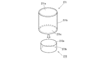
- FIG. 1 It is a 1st figure which shows schematic structure of the gas generator of this invention. It is a figure which shows schematic structure of the igniter applied to the gas generator shown in FIG. It is a figure which shows schematic structure of the accommodation cup and metal header applied to the igniter shown in FIG.
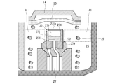
- the gas generator which concerns on Example 3 of this invention WHEREIN: It is a figure which shows schematic structure of a 2nd igniter and its periphery, Comprising: It is a figure showing the state before combustion of an ignition charge.
- FIG. 1 is a cross-sectional view of the gas generator 1 in the height direction.
- the gas generator 1 is configured to burn the gas generating agent filled in the housing 4 formed by the upper shell 2 and the lower shell 3 to release the combustion gas.
- the gas generator 1 is a so-called dual type gas generator in which two combustion chambers are vertically arranged as described later, and corresponding igniters and gas generating agents are arranged in each combustion chamber.
- the upper shell 2 has a peripheral wall portion 2c and a top surface portion 2d, which form a concave internal space.
- the top surface 2d has a substantially circular shape in a top view together with the bottom surface 3b of the lower shell 3 described later, and the peripheral wall 2c and the peripheral wall 3a of the lower shell 3 described later respectively have the top surface 2d and the bottom surface It encloses the circumference of 3b, and forms an annular wall which extends approximately perpendicularly from each surface.
- the internal space of the upper shell 2 is a first combustion chamber 21 filled with a first gas generating agent 22 as described later.
- the top surface 2d is connected to one end of the peripheral wall 2c, and the other end is an opening of the upper shell 2.
- the fitting wall 2a and the butting part 2b are provided in the said other end side of the surrounding wall part 2c sequentially from the said opening part.
- the radius of the internal space by the fitting wall 2a is larger than the radius of the internal space by the peripheral wall 2c near the top surface 2d, and the fitting wall 2a is connected to the peripheral wall 2c via the butting portion 2b ing.
- the lower shell 3 has a peripheral wall 3a and a bottom 3b, which form a concave internal space.
- the internal space is the second combustion chamber 25 filled with the second gas generating agent 26.
- the bottom surface 3b is connected to one end of the peripheral wall 3a, and the other end is an opening of the lower shell 3.
- the radius of the internal space by the peripheral wall 3 a is substantially the same as the radius of the internal space by the peripheral wall 2 c of the upper shell 2.
- the bottom portion 3 b of the lower shell 3 is provided with holes to which the first igniter 23 and the second igniter 27 are respectively fixed.
- a dividing wall 10 is disposed between the upper shell 2 and the lower shell 3.
- the dividing wall 10 has an end portion 15, a dividing wall portion 14 which is connected to the end portion 15 and divides the inside of the housing 4 into substantially upper and lower spaces, and an accommodating wall member (housing wall) 16 which is connected to the dividing wall portion 14 and described later It has a peripheral wall 13 extending along and an end 12 disposed so as to partially cover the opening of the receiving wall member 16.
- the end 12 forms a through hole 11.
- a cylindrical housing wall member 16 is provided on the bottom surface portion 3 b so as to surround the periphery of the first igniter 23 attached to the bottom surface portion 3 b of the lower shell 3 in the height direction.
- the upper opening of the housing wall member 16 is covered by the end 12 of the dividing wall 10. Further, a through hole 17 is provided in the housing wall member 16, and the through hole 17 communicates the two spaces (the first combustion chamber 21 and the second combustion chamber 25) formed by being divided by the dividing wall 10. Do.
- the upper shell 2 is further attached from above.
- the abutment portion 2b of the upper shell 2 is the dividing wall 10
- the lower shell 3 is fitted until it abuts on the end 15 of the lower shell 3.
- the fitting portion and the contact portion between the upper shell 2 and the lower shell 3 are joined by a suitable bonding method (for example, welding etc.) for the purpose of preventing moisture of the gas generating agent filled therein. .
- the dividing wall 10 divides the interior space of the housing 4 into two substantially upper and lower spaces.
- a first igniter 23 and a first gas generating agent 22 are disposed in a first combustion chamber 21 defined by the upper shell 2 and the dividing wall 10 in the internal space of the housing 4, and the lower shell 3 and the dividing wall 10
- the second igniter 27 and the second gas generating agent 26 are disposed in the second combustion chamber 25 defined, so that the gas generator 1 includes the two first igniters 23 and the second igniters 27. It is configured as a dual type gas generator.
- the first igniter 23 and the second igniter 27 are both fixed on the bottom surface portion 3b of the lower shell 3. Therefore, in the first igniter 23, the side of the first igniter 23 is an accommodation wall member. It is in the state of being surrounded by 16.
- the first igniter 23 is housed in the first space, and the space above the first igniter 23 is filled with the first gas generating agent 22, and the annular filter 32 is disposed to surround the first gas generating agent 22. There is. At this time, the first gas generating agent 22 is filled in a state in which the filter 32, the divided wall portion 14 and the like are suppressed by the biasing force of the cushion 31 so as to prevent unnecessary vibration in the first combustion chamber 21.
- the first gas generating agent 22 uses a gas generating agent having a relatively low combustion temperature.
- the combustion temperature of the first gas generant 22 is desirably in the range of 1000 to 1700 ° C., and is composed of, for example, guanidine nitrate (41% by weight), basic copper nitrate (49% by weight) and binders and additives.
- a single-hole cylinder can be used.
- the internal space of the housing wall member 16 may be filled with a gas generating agent having a composition different from that of the first gas generating agent 22.
- the composition of the gas generating agent filled in the internal space of the housing wall member 16 is configured such that the combustion temperature is higher than that of the first gas generating agent 22 in order to promote the ignition of the first gas generating agent 22. It can be done.
- the filter 32 is formed by overlapping stainless steel flat braided wire netting in the radial direction and compressing it in the radial and axial directions, cooling the combustion gas by the first gas generating agent 22, and removing the combustion residue Collect.
- As the filter 32 it is also possible to adopt a winding type structure formed by winding a wire in multiple layers around a mandrel.
- the filter 32 also collects the combustion residue of the second gas generating agent 26 filled in the second combustion chamber 25. Further, by the gap 33 formed between the peripheral wall portion 2 c of the upper shell 2 and the filter 32, an annular gas passage is formed around the filter 32 in a radial direction cross section.
- the gap 33 allows the combustion gas to pass through the entire area of the filter 32, and the effective use of the filter 32 and the effective cooling and purification of the combustion gas are achieved.
- the combustion gas flowing through the gap 33 reaches the gas outlet 5 provided in the peripheral wall 2c. Further, before the gas generator 1 is operated, the gas outlet 5 is closed from the inside of the housing 4 by the aluminum tape 34 in order to prevent moisture from entering the housing 4 from the outside.
- the second gas generating agent 26 is filled corresponding to the second igniter 27 fixed to the bottom surface portion 3 b of the lower shell 3. In this case, a relatively large amount of the second gas generating agent 26 is easily filled on the bottom surface 3 b side of the lower shell 3 around the second igniter 27 in the second combustion chamber 25.
- the second gas generating agent 26 is also charged in a state of being biased by the cushion 35 so as to prevent unnecessary vibration in the second combustion chamber 25.
- the second gas generating agent 26 also has guanidine nitrate (41% by weight), basic copper nitrate (49% by weight), a binder and additives, and has a single-hole cylindrical shape. Can be used.
- the combustion of the first gas generating agent 22 by the operation of the first igniter 23 and the combustion of the second gas generating agent 26 by the operation of the second igniter 27 The form of the emission of the combustion gas to the fuel can be adjusted in various ways. Also, a relatively large amount of combustion gas can be generated and released to the outside.
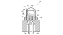
- the second igniter 27 is an electric igniter, and as shown in FIG. 2, a space for accommodating the igniter 272 is accommodated by a metal accommodation cup 271 whose surface is covered with an insulating cover. It is defined in 271.
- a metal header 273 is disposed in the space, and a cylindrical charge holder 274 is provided on the top surface thereof.
- the charge holder 274 holds the igniter 272.
- the housing cup 271 has a bottom surface portion 271 a, a peripheral wall portion 271 b, and an opening portion 271 c.
- the bottom surface 271a and the peripheral wall 271b of the housing cup 271 cover the top surface 273a and the peripheral surface 273b of the metal header 273 so that the housing cup 271 and the metal header 273 are fixed. It is formed.
- the igniter 272 is sealed in the storage chamber 275. Further, a bridge wire 276 electrically connecting one of the conductive pins 278 and the metal header 273 is wired at the bottom of the igniter 272 contained in the containing chamber 275.
- the two conductive pins 278 are fixed to the metal header 273 via the insulator 277 so that the two conductive pins 278 are in an insulated state when no voltage is applied.
- the opening 271 c defined at the periphery of the housing cup 271 on the metal header 273 side is protected by the resin collar 279 in a state in which the insulation between the conductive pins 278 is well maintained.
- the second igniter 27 when a voltage is applied between the two conductive pins 278 by the external power supply, a current flows in the bridge wire 276, whereby the igniter 272 burns.
- the bridge wire 276 for burning the igniter 272 corresponds to the ignition unit in the present invention.
- ZPP zirconium and potassium perchlorate
- THPP pyrotechnic charge containing titanium hydride and potassium perchlorate
- APP Explosives containing aluminum and potassium perchlorate
- ABO Explosives containing aluminum and bismuth oxide
- AMO aluminum and molybdenum oxide
- AlCO aluminum And explosives comprising copper oxide
- ACO explosives comprising aluminum and iron oxide
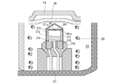
- the ignition charge 272 burns, a combustion product is generated. Then, the combustion product is ejected from the charge holder 274. At this time, the combustion products ejected from the upper end of the charge holder 274 tend to act mainly on the inner wall surface of the bottom portion 271 a of the accommodation cup 271 provided opposite to the upper end of the charge holder 274.
- the side (the range A1 in FIG. 4A), the upper side (the upper range than the range A1 in FIG. 4A), and the lower side of the storage chamber 275 of the second igniter 27
- a combustion chamber space (second combustion chamber 25) is provided in a range (a range below the range A1 in FIG. 4A), and the space is filled with the second gas generating agent 26.
- the combustion product is released from the storage chamber 275 to the second combustion chamber 25 by cleavage of a predetermined portion of the bottom surface portion 271 a of the storage cup 271, the second combustion chamber 25 above the outside of the storage chamber 275.
- the combustion of the second gas generating agent 26 filled therein is likely to be promoted.
- the combustion of the second gas generating agent 26 filled in the second combustion chamber 25 on the side and the lower side outside the storage chamber 275 may be delayed, and the combustion of the gas generating agent may be uneven.
- the storage cup 271 of the second igniter 27 is desorbed from the second igniter 27 by the action of the combustion product generated by the combustion of the igniter 272 and in a predetermined direction. Moving. Then, in a state where the movement of the housing cup 271 is restricted by the cushion 35 and the dividing wall portion 14, the combustion product received by the housing cup 271 is made of the second igniter 27 by the peripheral wall portion 271 b of the housing cup 271. It is directed to the side (ie, the bottom 3b side of the lower shell 3). As a result, combustion promotion of the 2nd gas generating agent 26 of the side and the lower part outside the storage chamber 275 is achieved. This will be described in detail below.
- the combustion products generated by the combustion of the ignition charge 272 are ejected from the upper end of the charge holder 274. Then, the combustion product ejected from the charge holder 274 acts on the inner wall surface of the storage cup 271. As a result, the fixed state of the housing cup 271 and the metal header 273 is not maintained, and the housing cup 271 is detached from the metal header 273 side. In addition, the storage cup 271 is fixed to the metal header 273 in the state before the ignition charge 272 is burned so that the storage cup 271 can be detached from the metal header 273 side by the combustion of the ignition charge 272. . Such a fixed state is realized by the fact that the receiving cup 271 and the metal header 273 are not fixed by welding.
- the housing cup 271 and the metal header 273 are mold-fixed by, for example, a resin collar 279.
- the housing cup 271 and the metal header 273 may be fixed by forming a recess in the circumferential surface 273b of the metal header 273 and lightly caulking a portion of the peripheral wall 271b of the housing cup 271 corresponding to the recess.
- the resin may be injected around the housing cup 271 and fixed by pressing the peripheral wall portion 271b of the housing cup 271 against the circumferential surface 273b of the metal header 273 by utilizing shrinkage upon curing.
- the sealing agent can be applied to the peripheral wall portion 271b of the housing cup 271 and the peripheral surface 273b of the metal header 273.
- the combustion product generated by the combustion of the igniter 272 continues to act on the inner wall surface of the housing cup 271.
- the predetermined direction in the present embodiment is a direction perpendicular to the bottom surface portion 271 a of the accommodation cup 271.
- the cushion 35 and the dividing wall portion 14 are provided in a predetermined direction from the second igniter 27. Therefore, the accommodation cup 271 which moves as mentioned above contacts the cushion 35 in the middle of the movement.
- the receiving cup 271 in contact with the cushion 35 continues to move in a predetermined direction while deforming the cushion 35, and is finally received by the dividing wall portion 14 via the cushion 35. That is, the movement of the receiving cup 271 is limited by the cushion 35 and the dividing wall portion 14, and the cushion 35 and the dividing wall portion 14 correspond to the limiting portion in the present invention.
- the housing cup 271 in the second combustion chamber 25 is in a state before the housing cup 271 is detached from the metal header 273 so that the movement space of the housing cup 271 detached from the metal header 273 side is suitably secured. It is preferable that the second gas generating agent 26 is not present above the bottom surface portion 271a.
- the second gas generating agent 26 is present, for example, a small opening is formed in the bottom surface portion 271 a of the storage cup 271, and the second gas above the bottom surface portion 271 a when the second igniter 27 operates.
- the moving space of the storage cup 271 detached from the metal header 273 can be suitably secured.
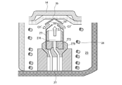
- FIG. 4B the receiving cup 271 is received by the dividing wall portion 14 via the cushion 35. Further, in such a state, a state in which the diameter of the opening 271 c of the accommodation cup 271 is expanded is formed. In this state, the housing cup 271 is detached from the metal header 273 side, and the metal forming the housing cup 271 is formed by elastic deformation or plastic deformation. The spread of the combustion products to the second combustion chamber 25 at this time will be described in detail below.
- the combustion products resulting from the combustion of the igniter 272 are ejected from the upper end of the charge holder 274 (this is represented by arrow C1 in FIG. 4B).
- the combustion product acts on the inner wall surface of the housing cup 271 and is reflected by the inner wall surface and spreads to the second combustion chamber 25.
- the flow of the combustion product reflected on the inner wall surface of the housing cup 271 is guided by the peripheral wall 271 b (this is represented by the arrow C2 in FIG. 4B).
- the combustion product is directed to the metal header 273 side (the second igniter 27 side).
- the combustion product is led to a wide range of the metal header 273 side (the second igniter 27 side). .
- the combustion of the second gas generating agent 26 disposed around the second igniter 27 can be promoted over a wide range.
- the upper end of the charge holder 274 is located in the space on the relatively upper side in the second combustion chamber 25, whereas the space in the vicinity of the bottom portion 3 b of the lower shell 3 in the second combustion chamber 25 is Since the space is the lowermost side in the combustion chamber 25, it is difficult for the combustion product to directly reach the space in the vicinity of the bottom portion 3b if there is no guide function of the storage cup 271 as described above.
- the combustion product can be directly delivered to the space of the second combustion chamber 25 in the vicinity of the bottom portion 3b by the guide function of the storage cup 271 described above. Ignition of the gas generating agent 26 is easily performed.
- the igniter 272 can be sealed in the storage chamber 275 without holding the igniter 272 by the charge holder 274.
- the charge holder 274 can be used as the second igniter 27. May not be provided.
- the gas generator according to the present invention described above it becomes possible to suitably burn the gas generating agent disposed around the igniter, thereby suppressing the uneven combustion of the gas generating agent as much as possible. And a suitable combustion gas generation capacity can be exhibited.
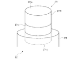
- FIG. 5 is a view showing a schematic configuration of a storage cup 271 according to the present modification.
- the housing cup 271 includes a thin walled portion 271d in the peripheral wall 271b.
- the thin portion 271d extends in the height direction of the peripheral wall 271b, is thinner than the other portion of the peripheral wall 271b, and is relatively fragile.
- the thin portion 271 d corresponds to the first fragile portion in the present invention.
- Example 1 is a dual type gas generator 1 as shown in FIG. 1, the gas generator to which the present invention is applied is limited to such a type of gas generator. I will not.
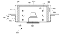
- the present invention can also be applied to, for example, a single type gas generator 100 as shown in FIG.
- the igniter 123 is fixed to the bottom surface portion 103 b of the lower shell 103 among the upper shell 102 and the lower shell 103 forming the housing 104. Then, the combustion of the gas generating agent 122 is performed in the combustion chamber 121 formed to surround the igniter 123. The combustion gas by the gas generating agent 122 passes through the filter 132 disposed to surround the gas generating agent 122 and reaches the gas outlet 105. The gas discharge port 105 is closed from the inside of the housing 104 by an aluminum tape 134 as in the gas generator 1 shown in FIG. 1 described above.
- the igniter 123 applied to the gas generator 100 is as described in the description of FIG. 2 and FIG. 3 above.
- the storage cup of the igniter 123 is operated from the igniter 123 by the action of the combustion product generated by the combustion of the igniter. Detach and move in a predetermined direction. The movement of the containing cup is limited by the cushion 131 and the top surface 102d of the upper shell 102. In such a state in which the movement of the containing cup is restricted, the combustion products received by the containing cup are directed to the side of the igniter 123 by the peripheral wall portion of the containing cup. As a result, combustion promotion of the gas generating agent 122 on the side and the lower side outside the storage chamber in the igniter 123 is achieved.
- the cushion 131 and the top surface portion 102d of the upper shell 102 correspond to the limiting portion in the present invention.
- the gas generating agent 122 present between the bottom surface portion of the storage cup of the igniter 123 and the cushion 131 is, for example, accommodated as in the gas generator 1 shown in FIG.
- a small opening can be formed in the bottom of the cup, and combustion products expelled from the opening can be used to burn preferentially. Thereby, the movement space of the accommodation cup detached from the metal header side can be secured suitably.
- FIG. 7 is a view showing a schematic configuration of a storage cup 271 according to the present embodiment.
- the housing cup 271 according to the present embodiment includes a thin walled portion 271 e in its peripheral wall 271 b.
- the thin portion 271 e extends in the circumferential direction of the peripheral wall 271 b and is thinner than the other portion of the peripheral wall 271 b and is relatively fragile.
- the thin portion 271e corresponds to the second fragile portion in the present invention.
- the housing cup 271 according to the present embodiment is fixed to the metal header 273 on the side of the opening 271 c in the peripheral wall 271 b.
- the thin-walled portion 271 e is formed on the peripheral wall portion 271 b closer to the bottom surface portion 271 a than the fixed portion.
- the adhesion between the housing cup 271 and the metal header 273 is realized, for example, by welding the housing cup 271 and the metal header 273.
- the second igniter 27 having such a storage cup 271
- the combustion product generated by the combustion of the igniter 272 acts on the inner wall surface of the storage cup 271
- the thin portion 271 e included in the peripheral wall 271 b is broken.
- a part of the peripheral wall 271b and the bottom 271a are integrally detached from the metal header 273 side.
- the peripheral wall 271b on the side of the opening 271c, which is another part of the peripheral wall 271b, is maintained in a state of being fixed to the metal header 273.
- the above-mentioned storage cup detached from the metal header 273 side moves from the second igniter 27 in the second combustion chamber 25 in a predetermined direction, and as shown in FIG. It is received by 14.
- a state in which the peripheral edge on the metal header 273 side is expanded is formed.
- This state is formed by elastic deformation or plastic deformation of the metal forming the accommodation cup 271 detached from the metal header 273 side, as in the first embodiment described above.
- the combustion product reflected on the inner wall surface of the accommodation cup 271 detached from the metal header 273 side is guided in its flow by the broken peripheral wall portion 271 b (this is represented by the arrow C2 in FIG. 8) ).
- the combustion product is directed to the metal header 273 side (the second igniter 27 side).
- the combustion products directed in this way are led to a wide range of the metal header 273 side (the second igniter 27 side) of the second combustion chamber 25. Thereby, the combustion of the second gas generating agent 26 disposed around the second igniter 27 can be promoted over a wide range.
- FIG. 9 is a view showing a schematic configuration of an igniter according to the present embodiment.
- the second igniter 27 in the gas generator 1 shown in FIG. 1 will be described as an example.
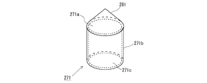
- the auxiliary cup 281 is provided to cover the bottom surface portion 271 a of the housing cup 271.
- the auxiliary cup 281 is a conical cup as shown in FIG.
- a 2nd igniter 27 discharges a combustion product to the exterior of the storage chamber 275, when the predetermined site
- the bottom surface portion 271a of the housing cup 271 is covered by the auxiliary cup 281 before the ignition charge 272 is burned. Therefore, a predetermined portion of the bottom surface portion 271a (which is represented as a portion belonging to the area A2 in FIG. 11A) is also covered by the auxiliary cup 281.
- a predetermined space is formed by the bottom surface portion 271a of the accommodation cup 271 and the auxiliary cup 281, and the wall surface of the auxiliary cup 281 defining the predetermined space is defined as the auxiliary cup inner wall surface 281a.
- the combustion product acts on the inner wall surface 281a of the auxiliary cup. That is, the auxiliary cup inner wall surface 281a corresponds to the pressure receiving surface in the present invention. Then, the auxiliary cup 281 moves away from the housing cup 271 and moves in a predetermined direction from the second igniter 27 in the second combustion chamber 25.
- the movement of the auxiliary cup 281 is restricted by the cushion 35 and the dividing wall portion 14.
- the auxiliary cup 281 is fixed to the storage cup 271 before combustion of the ignition charge 272 so that the auxiliary cup 281 can be detached from the storage cup 271 by combustion of the ignition charge 272.
- the housing cup 271 is fixed to the metal header 273 so that the housing cup 271 is not detached from the metal header 273 by the combustion of the igniter 272.
- adhesion is realized, for example, by welding the receiving cup 271 and the metal header 273.
- Gas generator 2 Upper shell 3: Lower shell 4: Housing 5: Gas outlet 10: Divided wall 14: Divided wall portion 16: Containment wall member 21: First combustion chamber 22: First gas generating agent 23: First igniter 25: second combustion chamber 26: second gas generating agent 27: second igniter 31, 35: cushion 32: filter 271: accommodation cup 271a: bottom 271b: peripheral wall 271c: opening 271d, 271e : Thin-walled portion 272: Ignition agent 273: Metal header 274: Charge holder 275: Containment chamber 276: Bridge wire 277: Insulator 278: Conductive pin 279: Resin collar 281: Auxiliary cup 281a: Auxiliary cup inner wall surface
Landscapes
- Chemical & Material Sciences (AREA)
- Physics & Mathematics (AREA)
- Fluid Mechanics (AREA)
- Engineering & Computer Science (AREA)
- Mechanical Engineering (AREA)
- Organic Chemistry (AREA)
- Chemical Kinetics & Catalysis (AREA)
- Air Bags (AREA)
- Feeding, Discharge, Calcimining, Fusing, And Gas-Generation Devices (AREA)
Abstract
Description
図1は、ガス発生器1の高さ方向の断面図である。ガス発生器1は、上部シェル2及び下部シェル3で形成されるハウジング4内に充填されたガス発生剤を燃焼させて、燃焼ガスを放出するように構成されている。なお、ガス発生器1は、後述するように2つの燃焼室が上下に配置され、各燃焼室に、対応する点火器及びガス発生剤を配置した、いわゆるデュアルタイプのガス発生器である。ここで、上部シェル2は周壁部2cと頂面部2dを有し、これらにより凹状の内部空間を形成する。頂面部2dは、後述の下部シェル3の底面部3bとともに、上面視で概ね円形状を有しており、周壁部2c及び後述の下部シェル3の周壁部3aは、それぞれ頂面部2d、底面部3bの周囲を囲み、各面部から概ね垂直に延在した環状の壁面を形成している。上部シェル2の内部空間は、後述するように第1ガス発生剤22が充填される第1燃焼室21となる。周壁部2cの一端側に頂面部2dが接続し、その他端側は上部シェル2の開口部となる。そして、周壁部2cの当該他端側には、当該開口部から順に、嵌合壁部2a、突き当て部2bが設けられている。嵌合壁部2aによる内部空間の半径は、頂面部2d寄りの周壁部2cによる内部空間の半径より大きく形成され、嵌合壁部2aは、突き当て部2bを介して周壁部2cへと繋がっている。
次に、上述した実施例1の第1の変形例について、図5に基づいて説明する。なお、本変形例において、上述した実施例1と実質的に同一の構成については、その詳細な説明を省略する。図5は、本変形例に係る収容カップ271の概略構成を示す図である。
次に、上述した実施例1の第2の変形例について、図6に基づいて説明する。なお、本変形例において、上述した実施例1と実質的に同一の構成については、その詳細な説明を省略する。上述した実施例1におけるガス発生器は、図1に示したようなデュアルタイプのガス発生器1であるが、本発明が適用されるガス発生器は、このようなタイプのガス発生器に限定されない。本発明は、例えば図6に示すようなシングルタイプのガス発生器100に適用することもできる。
次に、本発明の第2の実施例について、図7及び図8に基づいて説明する。なお、本実施例において、上述した実施例1と実質的に同一の構成については、その詳細な説明を省略する。図7は、本実施例に係る収容カップ271の概略構成を示す図である。
次に、本発明の第3の実施例について、図9から図11Bに基づいて説明する。なお、本実施例において、上述した実施例1と実質的に同一の構成については、その詳細な説明を省略する。図9は、本実施例に係る点火器の概略構成を示す図である。本実施例では、上記の図1に示したガス発生器1における第2点火器27を例にして説明する。本実施例に係る第2点火器27では、図9に示すように、補助カップ281が、収容カップ271の底面部271aを覆うように設けられている。この補助カップ281は、図10に示すような円錐状のカップである。
2 :上部シェル
3 :下部シェル
4 :ハウジング
5 :ガス排出口
10 :分割壁
14 :分割壁部
16 :収容壁部材
21 :第1燃焼室
22 :第1ガス発生剤
23 :第1点火器
25 :第2燃焼室
26 :第2ガス発生剤
27 :第2点火器
31、35 :クッション
32 :フィルタ
271 :収容カップ
271a :底面部
271b :周壁部
271c :開口部
271d、271e :薄肉部
272 :点火薬
273 :金属ヘッダー
274 :チャージホルダ
275 :収容室
276 :ブリッジワイヤ
277 :絶縁体
278 :導電ピン
279 :樹脂カラー
281 :補助カップ
281a :補助カップ内壁面
Claims (8)
- 火薬が収容された収容室と、該収容室に設けられ、火薬を着火させる着火部と、を備える点火器であって、該点火器での火薬燃焼で生じる燃焼生成物を受ける受圧面を有する脱離部であって、該受圧面への該燃焼生成物による作用により、該点火器から脱離して所定の方向に移動できるように構成された脱離部を有する点火器と、
前記点火器での火薬燃焼により、前記収容室の外側に充填されたガス発生剤の燃焼が行われる燃焼室であって、該点火器を取り囲むように形成された燃焼室と、
前記燃焼室内に配置された前記点火器から前記所定の方向にある所定位置に設けられた制限部であって、前記脱離部の該所定の方向への移動を制限する制限部と、
を備える、ガス発生器であって、
前記脱離部は、前記制限部によって該脱離部の前記所定の方向への移動が制限された状態において、前記受圧面で受けた燃焼生成物を前記点火器の側に指向させるガイド部を更に有する、
ガス発生器。 - 前記点火器は、
前記着火部が固定されたヘッダーと、
前記着火部に対向するように配置される底面部と、該底面部の周縁に接続され且つ該着火部を囲むように配置される周壁部とを含むカップであって、該周壁部と該底面部により前記収容室を形成する収容カップと、
を更に有し、
前記脱離部は前記収容カップであって、該収容カップの内壁面が前記受圧面であって、前記周壁部が前記ガイド部として前記燃焼生成物を前記ヘッダーの側に指向させる、
請求項1に記載のガス発生器。 - 前記収容カップは、前記点火器での火薬燃焼により、該収容カップが前記ヘッダー側から脱離可能となるように、該点火器での火薬燃焼前の状態において前記ヘッダーに固定され、
前記点火器での火薬燃焼により、前記所定の方向に脱離した前記収容カップの移動が前記制限部によって制限された状態において、該収容カップの前記ヘッダー側の周縁で画定される開口部が拡径し、該拡径した開口部を有する該周壁部が、前記燃焼生成物を前記ヘッダーの側に指向させる、
請求項2に記載のガス発生器。 - 前記収容カップは、前記周壁部に、前記燃焼生成物の作用により該収容カップの前記開口部を拡径させるように変形する第1脆弱部を含む、
請求項3に記載のガス発生器。 - 前記収容カップは、前記周壁部に、前記燃焼生成物の作用により該収容カップの一部が前記ヘッダー側から脱離可能となるように破断する第2脆弱部を含み、
前記点火器での火薬燃焼により、前記第2脆弱部が破断することによって、該ヘッダー側から脱離した前記収容カップの一部における前記周壁部が、前記燃焼生成物を前記ヘッダーの側に指向させる、
請求項2に記載のガス発生器。 - 前記収容カップは、前記ヘッダーに固定されるとともに、前記周壁部のうち該収容カップの該ヘッダー側の周縁で画定される開口部の側において該ヘッダーに固着され、更に前記底面部寄りの前記周壁部に前記第2脆弱部を形成し、
前記点火器での火薬燃焼により、前記第2脆弱部が破断することによって、前記周壁部の一部と前記底面部が一体となって前記ヘッダー側から脱離する、請求項5に記載のガス発生器。 - 前記点火器は、
前記着火部が固定されたヘッダーと、
前記着火部に対向するように配置される底面部と、該底面部の周縁に接続され且つ該着火部を囲むように配置される周壁部とを含むカップであって、該周壁部と該底面部により前記収容室を形成する収容カップと、
を更に有し、
前記収容カップは、所定部位が開裂することで前記燃焼生成物を前記収容室の外部に放出させ、
前記脱離部は、前記収容カップから放出される燃焼生成物を受ける前記受圧面を有し、該収容カップの前記所定部位を覆って設けられた補助カップであって、
前記点火器での火薬燃焼により、前記収容カップから離間して前記所定の方向に脱離した前記補助カップの移動が前記制限部によって制限された状態において、該補助カップの一部分が、前記ガイド部として前記燃焼生成物を該点火器の側に指向させる、
請求項1に記載のガス発生器。 - 請求項1から請求項7の何れか1項に記載のガス発生器において、
前記点火器を収容するハウジングであって、その内部に前記燃焼室を有するハウジングを備え、
前記ハウジングの内部に、前記燃焼室を上下に分割し、上側に位置する第1燃焼室と下側に位置する第2燃焼室とを形成する分割壁が設けられ、
前記ハウジングの底面に、前記第1燃焼室に充填された第1ガス発生剤を燃焼する第1点火器と、前記第2燃焼室に充填された第2ガス発生剤を燃焼する第2点火器とが配置され、
前記分割壁は、前記底面に配置された前記第1点火器を取り囲み前記第1燃焼室内に該第1点火器を収容する収容壁を含み、
前記第2点火器は前記脱離部を有し、且つ、前記制限部は、前記第2燃焼室内において該第2点火器から前記所定の方向に位置する前記分割壁の一部であって、
前記脱離部の前記ガイド部は、前記分割壁の一部によって該脱離部の前記所定の方向への移動が制限された状態において、前記燃焼生成物を前記第2点火器の側に指向させる、
ガス発生器。
Priority Applications (4)
| Application Number | Priority Date | Filing Date | Title |
|---|---|---|---|
| US16/631,515 US11173868B2 (en) | 2017-07-20 | 2018-07-09 | Gas generator |
| KR1020207004508A KR20200029556A (ko) | 2017-07-20 | 2018-07-09 | 가스 발생기 |
| CN201880048730.5A CN110944879B (zh) | 2017-07-20 | 2018-07-09 | 气体发生器 |
| DE112018003685.5T DE112018003685B4 (de) | 2017-07-20 | 2018-07-09 | Gasgenerator |
Applications Claiming Priority (2)
| Application Number | Priority Date | Filing Date | Title |
|---|---|---|---|
| JP2017-140938 | 2017-07-20 | ||
| JP2017140938A JP6888228B2 (ja) | 2017-07-20 | 2017-07-20 | ガス発生器 |
Publications (1)
| Publication Number | Publication Date |
|---|---|
| WO2019017229A1 true WO2019017229A1 (ja) | 2019-01-24 |
Family
ID=65015720
Family Applications (1)
| Application Number | Title | Priority Date | Filing Date |
|---|---|---|---|
| PCT/JP2018/025931 Ceased WO2019017229A1 (ja) | 2017-07-20 | 2018-07-09 | ガス発生器 |
Country Status (6)
| Country | Link |
|---|---|
| US (1) | US11173868B2 (ja) |
| JP (1) | JP6888228B2 (ja) |
| KR (1) | KR20200029556A (ja) |
| CN (1) | CN110944879B (ja) |
| DE (1) | DE112018003685B4 (ja) |
| WO (1) | WO2019017229A1 (ja) |
Families Citing this family (5)
| Publication number | Priority date | Publication date | Assignee | Title |
|---|---|---|---|---|
| JP6946097B2 (ja) * | 2017-07-21 | 2021-10-06 | 株式会社ダイセル | ガス発生器 |
| JP7257190B2 (ja) * | 2019-03-06 | 2023-04-13 | 株式会社ダイセル | 点火器組立体、保持部の成形方法、及びガス発生器 |
| DE102019134899A1 (de) * | 2019-12-18 | 2021-06-24 | Zf Airbag Germany Gmbh | Gasgenerator insbesondere für ein fahrzeugsicherheitssystem |
| JP7534871B2 (ja) * | 2020-06-02 | 2024-08-15 | 株式会社ダイセル | ガス発生器及びその製造方法 |
| US11639227B2 (en) * | 2020-07-13 | 2023-05-02 | Goodrich Corporation | Inflation assemblies for evacuation systems |
Citations (4)
| Publication number | Priority date | Publication date | Assignee | Title |
|---|---|---|---|---|
| JP2010023752A (ja) * | 2008-07-23 | 2010-02-04 | Daicel Chem Ind Ltd | 人員拘束装置用インフレータ |
| WO2012153427A1 (ja) * | 2011-05-12 | 2012-11-15 | トヨタ自動車株式会社 | インフレータ及びエアバッグ装置 |
| JP2013226889A (ja) * | 2012-04-25 | 2013-11-07 | Daicel Corp | ガス発生器 |
| JP2016130116A (ja) * | 2015-01-15 | 2016-07-21 | 日本化薬株式会社 | ガス発生器 |
Family Cites Families (23)
| Publication number | Priority date | Publication date | Assignee | Title |
|---|---|---|---|---|
| JP3044097B2 (ja) | 1991-06-27 | 2000-05-22 | アイコム株式会社 | 無線送受信機 |
| US5536039A (en) * | 1994-12-06 | 1996-07-16 | Trw Inc. | Air bag inflator |
| US5622381A (en) | 1996-06-07 | 1997-04-22 | Morton International, Inc. | Integral projectile squid for air bag inflators |
| DE19725418A1 (de) * | 1997-06-16 | 1998-12-17 | Trw Airbag Sys Gmbh & Co Kg | Gasgenerator für eine Sicherheitseinrichtung |
| EP1155927B1 (en) | 1999-02-05 | 2006-03-29 | Nippon Kayaku Kabushiki Kaisha | Gas generator |
| JP3781603B2 (ja) * | 1999-02-05 | 2006-05-31 | 日本化薬株式会社 | ガス発生器 |
| US6974153B2 (en) * | 2002-04-25 | 2005-12-13 | Diacel Chemical Industries, Ltd. | Gas generator for an air belt apparatus and air belt apparatus |
| US7044501B2 (en) * | 2002-06-17 | 2006-05-16 | Daicel Chemical Industries, Ltd. | Inflator |
| DE20219899U1 (de) * | 2002-12-23 | 2003-05-28 | TRW Airbag Systems GmbH, 84544 Aschau | Gasgenerator |
| US20050189753A1 (en) * | 2004-02-10 | 2005-09-01 | Kazuhiro Kato | Gas generator |
| JP5255967B2 (ja) * | 2008-09-19 | 2013-08-07 | 株式会社ダイセル | ガス発生器 |
| DE102008060305A1 (de) * | 2008-12-03 | 2010-06-10 | Trw Airbag Systems Gmbh | Gasgenerator |
| JP2012040943A (ja) | 2010-08-19 | 2012-03-01 | Nippon Kayaku Co Ltd | ガス発生器 |
| WO2011142395A1 (ja) * | 2010-05-13 | 2011-11-17 | 日本化薬株式会社 | ガス発生器 |
| JP5944270B2 (ja) * | 2012-08-29 | 2016-07-05 | 日本化薬株式会社 | ガス発生器 |
| JP6243404B2 (ja) * | 2013-03-29 | 2017-12-06 | 日本化薬株式会社 | ガス発生器 |
| DE102013110810B4 (de) * | 2013-09-30 | 2017-03-02 | Takata AG | Gasgenerator für ein Airbagmodul |
| DE102014010942A1 (de) * | 2014-07-28 | 2016-01-28 | Trw Airbag Systems Gmbh | Gasgenerator für ein Fahrzeuginsassensicherheitssystem, Gassackmodul und Fahrzeuginsassensicherheitssystem mit einem solchen Gasgenerator sowie Herstellungsverfahren |
| JP6282555B2 (ja) * | 2014-08-01 | 2018-02-21 | 株式会社ダイセル | ガス発生器 |
| JP6758329B2 (ja) * | 2016-02-10 | 2020-09-23 | 日本化薬株式会社 | ガス発生器 |
| JP6691442B2 (ja) * | 2016-06-27 | 2020-04-28 | 株式会社ダイセル | ガス発生器 |
| JP6714495B2 (ja) * | 2016-11-10 | 2020-06-24 | 株式会社ダイセル | ガス発生器 |
| JP6880505B2 (ja) * | 2017-07-14 | 2021-06-02 | 株式会社ダイセル | 放出装置、及びガス発生器 |
-
2017
- 2017-07-20 JP JP2017140938A patent/JP6888228B2/ja active Active
-
2018
- 2018-07-09 DE DE112018003685.5T patent/DE112018003685B4/de active Active
- 2018-07-09 KR KR1020207004508A patent/KR20200029556A/ko not_active Withdrawn
- 2018-07-09 US US16/631,515 patent/US11173868B2/en active Active
- 2018-07-09 CN CN201880048730.5A patent/CN110944879B/zh active Active
- 2018-07-09 WO PCT/JP2018/025931 patent/WO2019017229A1/ja not_active Ceased
Patent Citations (4)
| Publication number | Priority date | Publication date | Assignee | Title |
|---|---|---|---|---|
| JP2010023752A (ja) * | 2008-07-23 | 2010-02-04 | Daicel Chem Ind Ltd | 人員拘束装置用インフレータ |
| WO2012153427A1 (ja) * | 2011-05-12 | 2012-11-15 | トヨタ自動車株式会社 | インフレータ及びエアバッグ装置 |
| JP2013226889A (ja) * | 2012-04-25 | 2013-11-07 | Daicel Corp | ガス発生器 |
| JP2016130116A (ja) * | 2015-01-15 | 2016-07-21 | 日本化薬株式会社 | ガス発生器 |
Also Published As
| Publication number | Publication date |
|---|---|
| KR20200029556A (ko) | 2020-03-18 |
| US11173868B2 (en) | 2021-11-16 |
| DE112018003685T5 (de) | 2020-04-30 |
| JP6888228B2 (ja) | 2021-06-16 |
| CN110944879A (zh) | 2020-03-31 |
| CN110944879B (zh) | 2022-05-06 |
| JP2019018783A (ja) | 2019-02-07 |
| US20200172044A1 (en) | 2020-06-04 |
| DE112018003685B4 (de) | 2025-10-23 |
Similar Documents
| Publication | Publication Date | Title |
|---|---|---|
| WO2019017229A1 (ja) | ガス発生器 | |
| JP3968367B2 (ja) | 二段式火工品技術エアバックインフレータ | |
| JP5090184B2 (ja) | ガスアクチュエータ用小型ガス発生器及びプリテンショナーシステム | |
| CN102271973B (zh) | 气体发生器 | |
| CN107176134B (zh) | 混合动力充气机、安全气囊单元、车辆安全系统及形成冲击波的方法 | |
| US6899351B2 (en) | Gas generator | |
| US8459692B2 (en) | Gas generator and method for assembling same | |
| KR20190017052A (ko) | 액추에이터 | |
| WO2022209798A1 (ja) | ガス発生器 | |
| EP3037163B1 (en) | Gas generator | |
| WO2019111566A1 (ja) | ガス発生器 | |
| CN100577274C (zh) | 用于气囊的气体发生器 | |
| JP7765363B2 (ja) | ガス発生器 | |
| JP2012091110A (ja) | ガス発生器およびガス発生器用ホルダ | |
| JP2018158690A (ja) | 点火器の固定構造、及び点火器の固定方法 | |
| US20250172373A1 (en) | Initiator, initiator device, and method for manufacturing initiator | |
| JP7361660B2 (ja) | ガス発生器 | |
| JP2015024681A (ja) | エアバッグ用インフレータ | |
| JP2009179288A (ja) | ガス発生器 | |
| JP2021195099A (ja) | ガス発生器 | |
| CN117320930A (zh) | 气体发生器 | |
| JP2014184835A (ja) | エアバッグ用インフレータ | |
| WO2018220950A1 (ja) | ガス発生器、及びデュアルタイプのガス発生器の組立方法 | |
| JP2016112941A (ja) | インフレータ | |
| JP2010254083A (ja) | ガス発生器 |
Legal Events
| Date | Code | Title | Description |
|---|---|---|---|
| 121 | Ep: the epo has been informed by wipo that ep was designated in this application |
Ref document number: 18835851 Country of ref document: EP Kind code of ref document: A1 |
|
| ENP | Entry into the national phase |
Ref document number: 20207004508 Country of ref document: KR Kind code of ref document: A |
|
| 122 | Ep: pct application non-entry in european phase |
Ref document number: 18835851 Country of ref document: EP Kind code of ref document: A1 |
|
| WWG | Wipo information: grant in national office |
Ref document number: 112018003685 Country of ref document: DE |