WO2019017125A1 - Glass shaping method and glass-shaped article formed by said method - Google Patents
Glass shaping method and glass-shaped article formed by said method Download PDFInfo
- Publication number
- WO2019017125A1 WO2019017125A1 PCT/JP2018/022963 JP2018022963W WO2019017125A1 WO 2019017125 A1 WO2019017125 A1 WO 2019017125A1 JP 2018022963 W JP2018022963 W JP 2018022963W WO 2019017125 A1 WO2019017125 A1 WO 2019017125A1
- Authority
- WO
- WIPO (PCT)
- Prior art keywords
- glass
- mold
- forming
- grinding
- silicon
- Prior art date
Links
- 239000011521 glass Substances 0.000 title claims abstract description 207
- 238000000034 method Methods 0.000 title claims abstract description 48
- 238000007493 shaping process Methods 0.000 title abstract description 7
- 239000000463 material Substances 0.000 claims abstract description 49
- 238000000227 grinding Methods 0.000 claims abstract description 39
- 239000000758 substrate Substances 0.000 claims abstract description 24
- 238000000465 moulding Methods 0.000 claims abstract description 17
- 229910052710 silicon Inorganic materials 0.000 claims description 59
- 239000010703 silicon Substances 0.000 claims description 59
- 238000005498 polishing Methods 0.000 claims description 29
- OKTJSMMVPCPJKN-UHFFFAOYSA-N Carbon Chemical compound [C] OKTJSMMVPCPJKN-UHFFFAOYSA-N 0.000 claims description 28
- 229910052799 carbon Inorganic materials 0.000 claims description 28
- 238000007496 glass forming Methods 0.000 claims description 24
- 238000012545 processing Methods 0.000 claims description 17
- 238000005530 etching Methods 0.000 claims description 11
- 239000006060 molten glass Substances 0.000 claims description 7
- 238000003754 machining Methods 0.000 claims description 5
- 230000008030 elimination Effects 0.000 claims description 3
- 238000003379 elimination reaction Methods 0.000 claims description 3
- 229910052750 molybdenum Inorganic materials 0.000 claims description 2
- 229910052719 titanium Inorganic materials 0.000 claims description 2
- 229910052721 tungsten Inorganic materials 0.000 claims description 2
- 238000002844 melting Methods 0.000 abstract description 4
- 230000008018 melting Effects 0.000 abstract description 4
- 238000005520 cutting process Methods 0.000 abstract description 3
- 238000007796 conventional method Methods 0.000 abstract 1
- XUIMIQQOPSSXEZ-UHFFFAOYSA-N Silicon Chemical compound [Si] XUIMIQQOPSSXEZ-UHFFFAOYSA-N 0.000 description 58
- 239000002585 base Substances 0.000 description 23
- 239000000919 ceramic Substances 0.000 description 10
- WGTYBPLFGIVFAS-UHFFFAOYSA-M tetramethylammonium hydroxide Chemical compound [OH-].C[N+](C)(C)C WGTYBPLFGIVFAS-UHFFFAOYSA-M 0.000 description 6
- 238000005452 bending Methods 0.000 description 4
- 239000010432 diamond Substances 0.000 description 4
- 229910003460 diamond Inorganic materials 0.000 description 4
- 238000005516 engineering process Methods 0.000 description 4
- 238000009281 ultraviolet germicidal irradiation Methods 0.000 description 4
- VYZAMTAEIAYCRO-UHFFFAOYSA-N Chromium Chemical compound [Cr] VYZAMTAEIAYCRO-UHFFFAOYSA-N 0.000 description 2
- 239000011230 binding agent Substances 0.000 description 2
- 238000012993 chemical processing Methods 0.000 description 2
- 229910052804 chromium Inorganic materials 0.000 description 2
- 239000011651 chromium Substances 0.000 description 2
- 238000001816 cooling Methods 0.000 description 2
- 230000000694 effects Effects 0.000 description 2
- 229910052751 metal Inorganic materials 0.000 description 2
- 239000002184 metal Substances 0.000 description 2
- 239000012778 molding material Substances 0.000 description 2
- 239000000843 powder Substances 0.000 description 2
- 238000010008 shearing Methods 0.000 description 2
- 239000003513 alkali Substances 0.000 description 1
- 230000015572 biosynthetic process Effects 0.000 description 1
- 238000005336 cracking Methods 0.000 description 1
- 238000005553 drilling Methods 0.000 description 1
- 238000010894 electron beam technology Methods 0.000 description 1
- 238000010304 firing Methods 0.000 description 1
- 238000004519 manufacturing process Methods 0.000 description 1
- 150000002739 metals Chemical class 0.000 description 1
- 238000003801 milling Methods 0.000 description 1
- 230000004048 modification Effects 0.000 description 1
- 238000012986 modification Methods 0.000 description 1
- 238000000059 patterning Methods 0.000 description 1
- 230000002093 peripheral effect Effects 0.000 description 1
- 238000000206 photolithography Methods 0.000 description 1
- 238000001020 plasma etching Methods 0.000 description 1
- 229910052697 platinum Inorganic materials 0.000 description 1
- 239000010453 quartz Substances 0.000 description 1
- 230000003252 repetitive effect Effects 0.000 description 1
- 238000007789 sealing Methods 0.000 description 1
- VYPSYNLAJGMNEJ-UHFFFAOYSA-N silicon dioxide Inorganic materials O=[Si]=O VYPSYNLAJGMNEJ-UHFFFAOYSA-N 0.000 description 1
- 238000005245 sintering Methods 0.000 description 1
- 239000002002 slurry Substances 0.000 description 1
- HUAUNKAZQWMVFY-UHFFFAOYSA-M sodium;oxocalcium;hydroxide Chemical compound [OH-].[Na+].[Ca]=O HUAUNKAZQWMVFY-UHFFFAOYSA-M 0.000 description 1
- 230000002269 spontaneous effect Effects 0.000 description 1
Images


Classifications
-
- C—CHEMISTRY; METALLURGY
- C03—GLASS; MINERAL OR SLAG WOOL
- C03B—MANUFACTURE, SHAPING, OR SUPPLEMENTARY PROCESSES
- C03B19/00—Other methods of shaping glass
- C03B19/02—Other methods of shaping glass by casting molten glass, e.g. injection moulding
-
- C—CHEMISTRY; METALLURGY
- C03—GLASS; MINERAL OR SLAG WOOL
- C03B—MANUFACTURE, SHAPING, OR SUPPLEMENTARY PROCESSES
- C03B23/00—Re-forming shaped glass
- C03B23/0026—Re-forming shaped glass by gravity, e.g. sagging
-
- B—PERFORMING OPERATIONS; TRANSPORTING
- B24—GRINDING; POLISHING
- B24B—MACHINES, DEVICES, OR PROCESSES FOR GRINDING OR POLISHING; DRESSING OR CONDITIONING OF ABRADING SURFACES; FEEDING OF GRINDING, POLISHING, OR LAPPING AGENTS
- B24B7/00—Machines or devices designed for grinding plane surfaces on work, including polishing plane glass surfaces; Accessories therefor
- B24B7/20—Machines or devices designed for grinding plane surfaces on work, including polishing plane glass surfaces; Accessories therefor characterised by a special design with respect to properties of the material of non-metallic articles to be ground
- B24B7/22—Machines or devices designed for grinding plane surfaces on work, including polishing plane glass surfaces; Accessories therefor characterised by a special design with respect to properties of the material of non-metallic articles to be ground for grinding inorganic material, e.g. stone, ceramics, porcelain
- B24B7/24—Machines or devices designed for grinding plane surfaces on work, including polishing plane glass surfaces; Accessories therefor characterised by a special design with respect to properties of the material of non-metallic articles to be ground for grinding inorganic material, e.g. stone, ceramics, porcelain for grinding or polishing glass
- B24B7/241—Methods
-
- G—PHYSICS
- G04—HOROLOGY
- G04B—MECHANICALLY-DRIVEN CLOCKS OR WATCHES; MECHANICAL PARTS OF CLOCKS OR WATCHES IN GENERAL; TIME PIECES USING THE POSITION OF THE SUN, MOON OR STARS
- G04B1/00—Driving mechanisms
- G04B1/10—Driving mechanisms with mainspring
- G04B1/14—Mainsprings; Bridles therefor
- G04B1/145—Composition and manufacture of the springs
-
- G—PHYSICS
- G04—HOROLOGY
- G04B—MECHANICALLY-DRIVEN CLOCKS OR WATCHES; MECHANICAL PARTS OF CLOCKS OR WATCHES IN GENERAL; TIME PIECES USING THE POSITION OF THE SUN, MOON OR STARS
- G04B17/00—Mechanisms for stabilising frequency
- G04B17/04—Oscillators acting by spring tension
- G04B17/06—Oscillators with hairsprings, e.g. balance
- G04B17/066—Manufacture of the spiral spring
Definitions
- the present invention relates to a glass forming method capable of precisely performing machining such as grinding and / or polishing processing on a molded glass, and a glass formed product formed from the method.
- This invention is made in view of such a situation, Comprising: The glass forming method which can grind and / or grind a fine brittle material more stably than before, and the glass formed by the method The purpose is to provide a molded article.
- a forming step of forming a forming die having a recess using a base material which does not deform at a temperature higher than the softening point of glass, and more than the softening point of the glass Forming a softened glass or a molten glass in the concave portion of the mold by raising the temperature of the glass substrate at a temperature of 1, and cooling and solidifying the softened glass to form the glass substrate;
- a cross section of the concave portion of the mold with respect to the depth direction is ground and / or polished to form the glass molded product having the same planar shape as the cross surface of the concave portion.
- the base material is silicon
- the mold is removed by etching in the die removal step. It is preferable that the base material of the glass forming method is carbon, and the forming die disappears by burning out in the die elimination step.
- the glass forming method may include an additional glass forming step of grinding and / or polishing the glass substrate in the recess together with the remaining mold of the mold after forming the cut surface.
- the "glass softening point” refers to a temperature at which the glass is softened and deformed by its own weight to a viscosity of 10 7.65 dpa ⁇ s, and "disappear the base material of the mold”
- the term “free” refers to removal of part and all of the mold physically and chemically disappears, which does not include removal by simple mold release between the mold and the molding.
- softened glass refers to glass before 100% melting of the glass from the softening point of the glass
- melted glass refers to a state where the glass is completely melted 100%.
- a forming step of forming a forming die having a recess using a base material that does not deform at a temperature higher than the softening point of glass, and more than the softening point of the glass A glass forming step of raising the temperature of the glass substrate at a temperature of 50 ° C.
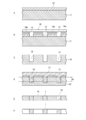
- FIG. 1A is a plan view of a silicon type of a mainspring of a watch produced in the first embodiment of the present invention
- FIG. 1B is a plan view of a glass mainspring molded by the silicon type of A of FIG.
- FIG. 2A is a partial cross-sectional view of a state in which the surface of a silicon plate is covered with a resist film
- FIG. 2B is a film as a resist film.
- FIG. 2C is a cross-sectional view of a state in which a silicon plate is etched to form a spiral groove and then a resist film is removed.
- FIG. 2D is a state in which softened glass is sealed on the surface of the silicon plate.
- FIG. 1A is a plan view of a silicon type of a mainspring of a watch produced in the first embodiment of the present invention
- FIG. 1B is a plan view of a glass mainspring molded by the silicon type of A of FIG.
- FIG. 2A is a partial cross-sectional
- FIG. 2E is a cross-sectional view of a state where the silicon mold is horizontally ground and / or polished
- FIG. 4F is a cross-sectional view of the spring with the silicon plate removed.
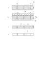
- 3A is a plan view of a carbon type of reticulated glass to be produced in the second embodiment of the present invention
- FIG. 3B is a plan view of the reticulated glass formed by the carbon type of A of FIG. Indicate It is a fragmentary sectional view of a formation process of mesh glass using carbon type of A of FIG. 3
- a of FIG. 4 is a cross section of carbon type in which a carbon plate was grooved in a mesh shape with a dicing saw and grooves were formed on the surface.
- FIG. 1 is a plan view of a mold of a glass balance spring
- B of FIG. 1 is a plan view of a balance spring formed of the silicon mold.
- the silicon mold 10 is a mold for molding a glass balance spring (hereinafter simply referred to as a spring) 1.
- the mainspring 1 gives an accurate period to a vibrating balance (not shown) of the watch and plays a role in determining the accuracy of the watch.
- the diameter of the spring 1 is about 5 mm
- the height is 0.1 mm
- the wall thickness is 0.04 mm
- the whole is a fine structure.
- the mold 10 for molding such a fine spring 1 is formed of silicon in the present embodiment.
- a to F in FIG. 2 show the process of forming the spring, and show only a partial cross section of the forming die 10 and the silicon plate 11 of the base material.
- the mold 10 uses a silicon plate 11 having a constant thickness as a base material, and the drawing shows a state in which a resist film 12 is formed on the silicon plate 11.
- the resist film 12 in a portion adapted to the planar shape of 1 is removed to form a spiral-shaped film groove 13.
- the film groove 13 is formed such that the depth direction of the groove is perpendicular to the mold 10.
- a resist film 12 is applied to the surface of the silicon plate 11.
- the mask 14 is disposed above the resist film 12.
- the mask 14 has, for example, a chromium film 14b deposited on a transparent quartz substrate 14a, and the portion where the chromium film 14b is not present has a shape corresponding to the flat (cross-sectional) shape of the spring 1.
- the resist pattern is exposed from above the mask 14 using, for example, ultraviolet light (UV).
- the resist film 12 is exposed to far ultraviolet rays, electron beams, X-rays, etc. in addition to ultraviolet rays.
- the exposed silicon plate 11 is dipped in a developer to remove the exposed portion of the resist film. In this process, the film groove 13 from which the resist film which is a pattern of the spring is removed appears on the silicon plate 11.
- a spiral spring (helix) shaped spiral spring on the silicon plate 11 along the film groove 13 The groove 15 is formed.
- the mold 10 shown in C of FIG. 2 is formed.
- the width of the spiral spring groove 15 formed in the mold 10 is 0.04 mm, which is the same as the thickness (plate) thickness of the spiral spring 1, and the groove depth is formed deeper than the height of the spiral spring 1.
- the forming die 10 may be a single body forming one spring 1 or may be a plurality of the spring 1 formed laterally or vertically in a silicon plate. In the case of multiple, it can be produced in large quantities by repetitive patterning. (Molding process)
- glass is sealed on the surface of the spiral groove 15 of the mold 10 as shown in FIG. 2D.
- One of the methods is to put a mold in a vacuum furnace, place a heat-resistant glass material on the mold, raise the temperature in the vacuum furnace above the softening point or softening point of the glass, and soften the glass. When it becomes deformed, softened glass is flowed into the spring groove 15 or pressed into it naturally. Since the mold 10 does not deform at the softening point of glass, the spiral spring groove 15 is formed accurately. After the glass is sealed in the spiral groove 15, the glass is cooled and solidified. When the softened glass does not easily enter the spiral groove 15, pressure may be applied to the softened glass.
- the mold 10 holding the glass in a grinding and / or polishing machine (not shown) is set as it is without releasing the glass and the mold 10. Then, the glass substrate 17 on the surface of the mold 10 shown in D of FIG. 2 is removed by grinding and / or polishing, and further, the front and back surfaces of the mold 10 are ground and / or polished.
- the silicon of the mold 10 and the glass in the spiral groove 15 are surface ground and / or polished to a thickness corresponding to H1. At this time, the glass layer overlapping the surface of the mold 10 is ground and / or polished, and the silicon base material of the mold 10 is also ground and / or polished together at the portion of the spiral groove 15.
- FIG. 2F is a cross-sectional view of the spring 1 with the residual silicon of FIG. 2E eliminated. Only the residual silicon (residual base material) 16 left from the mold 10 is eliminated by selective etching. In this embodiment, in order to cause the silicon to disappear by etching, the residual silicon is eliminated using TMAH (Tetra methyl ammonium hydroxide) as an etching material to form the spiral spring 1 as shown in B of FIG. (Type loss process)
- TMAH Tetra methyl ammonium hydroxide
- glass is a hard material and easily broken, and it is not a simple material when grinding and / or polishing microparts alone for forming purposes.
- the glass is ground and / or polished together with the mold 10 instead of grinding and / or polishing a single glass, the glass is integrally held by silicon, and shear force is applied during grinding and / or polishing. Even if it is, it is possible to prevent breakage of the brittle glass material. More precise grinding and / or polishing of glass can be made.
- the watch's balance spring has been created, it can also be applied to the manufacture of watch gears and other precision parts.
- FIG. 3A is a plan view of a mold formed from a wafer-like carbon plate
- FIG. 3B is a plan view of a reticulated glass molded by the mold.
- the mold 20 made of carbon is a mold for molding the mesh glass 2 made of glass.
- the width of one grid of the mesh glass 2 is 0.03 mm and the height is 1 mm.
- a to D in FIG. 4 show a forming process of the mesh glass 2 and show only a part of the mold 20, the mesh glass 2 and the like.
- the forming die 20 forms a mesh groove 21 by grooving a carbon plate as a base material lengthwise and crosswise with a dicing saw or the like. (Molding process)
- glass is sealed on the surface of the mold 20 as shown in FIG. 4B.
- One of the methods is to put the mold 20 in a vacuum furnace, place the heat-resistant glass material on the mold, raise the temperature in the vacuum furnace above the softening point or softening point of the glass, and soften the glass when the glass is softened. Naturally flow into the mesh groove 21 or press fit. Since the mold 20 does not deform or melt at the softening point of the glass, the mesh groove 21 does not deform. (Glass forming process)
- the mold 20 When the softened glass is cooled and solidified, the mold 20 is set as it is while holding the glass substrate 24 in a grinding and / or polishing machine (not shown) without releasing the glass and the mold 20. Then, as shown in C of FIG. 4, the glass on the surface of the mold 20 is removed by grinding and / or polishing, and further, the front and back surfaces of the mold 20 are ground and / or polished. The surface of the mold 20 and the glass substrate 24 of the mesh groove 21 are ground and / or polished to a thickness H2 corresponding to the length. At this time, the glass layer overlapping the surface of the mold 20 is ground and / or polished, and the carbon base material of the mold 20 is also ground and / or polished at the mesh groove 21 portion.
- FIG. 4D is a cross-sectional view of the reticulated glass in which carbon is eliminated. Only the residual carbon (residual base material) 23 left from the mold 20 is selectively dissipated. In order to eliminate carbon, since carbon itself burns, residual carbon 23 can be eliminated by burning and burning off the carbon in an incinerator. (Type loss process)
- FIG. 5 shows a minute prism 3.
- the prism 3 is used as a component of a medical camera.
- the prism 3 is composed of a substantially cylindrical main body 4, a prism portion 5 at the tip, and a positioning portion 6 formed on the side surface of the main body.
- Such a prism is produced by a mold 30 formed from a silicon wafer as shown in FIG.
- glass is sealed on the surface of the mold 30.
- One of the methods is to put a mold in a vacuum furnace, place a heat-resistant glass material on the mold, raise the temperature in the vacuum furnace above the softening point or softening point of the glass, and soften the glass when the glass is softened. Spontaneous flow or press-fit into the round hole 31. Since the mold 30 does not soften at the softening point of glass, the round hole 31 does not deform. (Glass forming process)
- the forming die 30 holding the glass at a fixed part of a grinding and / or polishing machine (not shown) is set as it is without releasing the glass and the forming die 30. Do.
- the glass on the surface of the mold 30 is removed by grinding and / or polishing, and further, the front and back surfaces of the mold 30 are ground and / or polished.
- the surface of the mold 30 and the round hole 31 are ground and / or polished to a thickness H3 corresponding to.
- the glass substrate 32 overlapping the surface of the mold 30 is ground and / or polished, and the silicon base material of the mold 30 is also ground and / or polished at the round holes 31.
- the two-sided prism portion is formed at the upper end portion of the cylindrical glass 33. Also in the grinding of the cylindrical glass 33, since the cylindrical glass 33 is integrally adhered to the residual silicon 34 of the forming die 30, it is possible to grind without damaging the fine glass without receiving any shearing force or bending stress.
- the positioning portion 6 of the prism 3 is ground. The grinding of the positioning portion 6 also axially grinds the outer peripheral surface of the main body 4 of the prism 3 together with the residual silicon 34 to form a flat surface. (Additional glass processing process)
- FIG. 7E is a cross-sectional view of the prism 3 with silicon removed. Only the residual silicon (residual base material) 34 left from the mold 30 is eliminated by selective etching. In order to eliminate silicon by etching, in the present embodiment, using TMAH as an etching material, the remaining silicon 34 is eliminated to form a prism as shown in FIG. (Type loss process)
- the relationship between the mold and the glass is that the mold does not soften (deform) or melt at a temperature above the softening point of the glass, but a mold of a material having a similar linear expansion coefficient to that of the glass that is the molding material Is preferred.
- a material of a mold having a softening point of heat-resistant glass of 820 ° C. and higher than the softening point of glass high melting point metals such as Ti, Mo, W and Pt can be used in addition to silicon and carbon.
- a metal mold since the mold disappears by selective etching, there is an advantage that the single body of the glass molded product can be easily taken out.
- the melting temperature of Si is 1414 ° C.
- carbon is 3370 ° C.
- Ti is 1668 ° C.
- Mo is 2623 ° C.
- W is 3387 ° C.
- Pt is 1772 ° C. depending on the type.
- the linear expansion coefficient of the glass that can be used as a base material is 3.3 ⁇ 10 ⁇ 6 / ° C. for non-alkali glass (Tenpax: registered trademark by Schott) and 9.0 ⁇ 10 ⁇ 6 / ° C. for soda lime D263 (manufactured by SCHOTT) is 7.2 ⁇ 10 ⁇ 6 / ° C.
- the molds and materials that can be used are: 3.9 ⁇ 10 -6 / ° C for Si, 3.3 ⁇ 10 -6 / ° C for carbon, 8.8 ⁇ 10 -6 / ° C for Ti, 5.1 ⁇ for Mo 10 ⁇ 6 / ° C., W is 4.5 ⁇ 10 ⁇ 6 / ° C., and Pt is 9.0 ⁇ 10 ⁇ 6 / ° C.
- the softened glass can be poured into the mold at a temperature equal to or higher than the softening point, and the molded fine glass can be machined to form a glass molded article.
- the difference in thermal expansion coefficient between the glass and the base material is preferably as small as possible from the viewpoint of accuracy.
- the mesh groove 21 and the round hole 31 can be produced by the same method as the softened glass.
- a difference in thermal expansion occurs between the glass and the mold rather than sealing the softened glass
- the present invention was explained in detail based on an embodiment, referring to an accompanying drawing, the present invention is not limited to the above-mentioned embodiment, and other modification is carried out, without deviating from the scope of the present invention Alternatively, changes are possible.
- the forming die 30 is formed of silicon in the third embodiment, the forming die may be changed to silicon to form a prism of a similar form with carbon, and in the second embodiment, the forming die is formed Although 20 is formed of carbon, it is possible to form a network glass of the same form by changing the mold to carbon and using silicon.
- grinding and / or polishing was taken as an example for machining of the glass substrates 17, 24, 32 contained in the residual molds 16, 23, 34, but other processes such as cutting are also included.
- a machine tool to which the processing of the above is applied a lathe, a drilling machine, a boring machine, a milling machine, a grinding machine, a gear cutting machine, an NC machine tool, a dicing saw or the like can be used.
- the glass substrate was processed with the shaping
Landscapes
- Engineering & Computer Science (AREA)
- Chemical & Material Sciences (AREA)
- Mechanical Engineering (AREA)
- Organic Chemistry (AREA)
- Manufacturing & Machinery (AREA)
- Ceramic Engineering (AREA)
- Inorganic Chemistry (AREA)
- Materials Engineering (AREA)
- Physics & Mathematics (AREA)
- General Physics & Mathematics (AREA)
- Metallurgy (AREA)
- Micromachines (AREA)
- Grinding And Polishing Of Tertiary Curved Surfaces And Surfaces With Complex Shapes (AREA)
- Surface Treatment Of Glass (AREA)
- Re-Forming, After-Treatment, Cutting And Transporting Of Glass Products (AREA)
Abstract
Provided is a glass shaping method that enables grinding and/or abrading a fine brittle material more stably than conventional methods. The glass shaping method according to the present invention comprises a mold forming step for forming a mold 10 by forming a surface of a base material having a higher melting point temperature than a glass softening point, a glass molding step for molding a glass substrate 17 by injecting softened glass into grooves 15 formed on a surface of the mold 10 by the forming step, a glass working step for cutting, grinding, and/or abrading the glass substrate 17 with the mold 10 fixed, to form a glass-shaped article 1, and a step for removing only the base material 16 of the mold 10 after the glass working step to release the glass molded article 1 from the mold.
Description
本発明は、型成形したガラスを精密に研削及び/又は研磨加工などの機械加工を行なうことができるガラス成形方法及びその方法から成形したガラス成形品に関する。
The present invention relates to a glass forming method capable of precisely performing machining such as grinding and / or polishing processing on a molded glass, and a glass formed product formed from the method.
脆性材料であるガラスそのものに研削及び/又は研磨などの機械加工を施す場合、その材料の脆さから、加工サイズや微細化するために限界があった。また、複雑な形状については加工そのものに限界があった。
そのような微細なガラスを形成するために、化学的な加工によって微細ガラスを形成する技術がある。例えば、特許文献1によると、ガラス成形品として時計に用いられるぜんまい形状のスプリングが開示されている。このようなスプリングはガラスを研削及び/又は研磨することによって、所定の厚さのガラス板を形成する。次いで、ガラス板の表面にぜんまい形状のマスクを覆い、ガラス表面のマスクで隠されていないガラス部分をUV照射によって変質し、変質した後に選択エッチングを行って除去し、ゼンマイ形状のガラス製成形品が化学的な加工によって形成されている。 When the glass itself, which is a brittle material, is subjected to mechanical processing such as grinding and / or polishing, there is a limit to the processing size and refinement due to the brittleness of the material. In addition, there is a limit in processing itself for complicated shapes.
In order to form such fine glass, there is a technology of forming fine glass by chemical processing. For example, according toPatent Document 1, a spring having a mainspring shape used for a watch as a glass molded product is disclosed. Such springs form a glass plate of a predetermined thickness by grinding and / or polishing the glass. Next, the mainspring-shaped mask is covered on the surface of the glass plate, and the glass portion not covered with the mask on the glass surface is altered by UV irradiation, and after being altered, selective etching is performed to remove it. Is formed by chemical processing.
そのような微細なガラスを形成するために、化学的な加工によって微細ガラスを形成する技術がある。例えば、特許文献1によると、ガラス成形品として時計に用いられるぜんまい形状のスプリングが開示されている。このようなスプリングはガラスを研削及び/又は研磨することによって、所定の厚さのガラス板を形成する。次いで、ガラス板の表面にぜんまい形状のマスクを覆い、ガラス表面のマスクで隠されていないガラス部分をUV照射によって変質し、変質した後に選択エッチングを行って除去し、ゼンマイ形状のガラス製成形品が化学的な加工によって形成されている。 When the glass itself, which is a brittle material, is subjected to mechanical processing such as grinding and / or polishing, there is a limit to the processing size and refinement due to the brittleness of the material. In addition, there is a limit in processing itself for complicated shapes.
In order to form such fine glass, there is a technology of forming fine glass by chemical processing. For example, according to
ガラスと同じ脆性材料であるセラミクスを、成形型を用いて微細なセラミクス成形品を形成する技術がある。例えば、特許文献2によると、圧電セラミクスを所定形状に形成するため、シリコン基材上に反応性イオンエッチング法を用いて複数の穴を開口するようにしてシリコン型を形成している。次いで、圧電セラミクス粉体とバインダーを含むスラリーを、穴内部を含むシリコン型表面上に塗布し、該塗布膜を乾燥させたのち、バインダーを除去し、圧電セラミクスの焼結温度の下で加圧して圧電セラミクス粉体を焼成し、焼成後シリコン型をエッチング除去して微細形状の圧電セラミクスを所定形状に形成している。
There is a technology for forming a fine ceramic molded article by using a mold which is a brittle material which is the same brittle material as glass. For example, according to Patent Document 2, in order to form a piezoelectric ceramic in a predetermined shape, a silicon mold is formed on a silicon substrate using reactive ion etching so as to open a plurality of holes. Next, a slurry containing a piezoelectric ceramic powder and a binder is applied onto the surface of the silicon mold including the inside of the hole, the coated film is dried, the binder is removed, and pressure is applied under the sintering temperature of piezoelectric ceramic. The piezoelectric ceramic powder is fired, and after firing, the silicon mold is etched away to form a fine-shaped piezoelectric ceramic in a predetermined shape.
上述したように、UV照射によって微細ガラスが形成される技術が特許文献1に開示され、ガラスと同様に脆性材料である微細セラミクスがシリコン型によって形成される技術が特許文献2に開示されている。
しかしながら、特許文献1のように、UV照射によって形成されたガラス製品をUV照射後にさらに研削及び/又は研磨が必要となる場合がある。研削及び/又は研磨の対象が腕時計用のガラススプリングのように微細である場合は、研削及び/又は研磨作業中に成形品が破損したり傷が付きやすく、加工が困難である。
また、特許文献2の焼成セラミクスによって形成されたセラミクス成形材をさらに成形型形状と異なる形状に形成するために、研削及び/又は研磨が必要となる場合がある。このような場合も、セラミクスが脆性材料であるので、特にそれらの成形品が微細である場合は、加工が困難である。 As described above,Patent Document 1 discloses a technology in which a fine glass is formed by UV irradiation, and Patent Document 2 discloses a technology in which a fine ceramic which is a brittle material like glass is formed by a silicon mold. .
However, as inPatent Document 1, it may be necessary to further grind and / or polish a glass product formed by UV irradiation after UV irradiation. If the object to be ground and / or polished is as fine as a glass spring for a watch, the molded product is easily damaged or scratched during the grinding and / or polishing operation, and processing is difficult.
Moreover, in order to form the ceramic molding material formed of the baking ceramic ofpatent document 2 in the shape different from a shaping | molding die shape further, grinding and / or grinding may be needed. Even in such a case, since ceramics is a brittle material, it is difficult to process, particularly when the molded articles thereof are fine.
しかしながら、特許文献1のように、UV照射によって形成されたガラス製品をUV照射後にさらに研削及び/又は研磨が必要となる場合がある。研削及び/又は研磨の対象が腕時計用のガラススプリングのように微細である場合は、研削及び/又は研磨作業中に成形品が破損したり傷が付きやすく、加工が困難である。
また、特許文献2の焼成セラミクスによって形成されたセラミクス成形材をさらに成形型形状と異なる形状に形成するために、研削及び/又は研磨が必要となる場合がある。このような場合も、セラミクスが脆性材料であるので、特にそれらの成形品が微細である場合は、加工が困難である。 As described above,
However, as in
Moreover, in order to form the ceramic molding material formed of the baking ceramic of
本発明はこのような事情に鑑みてなされたものであって、微細な脆性材料を従来よりも安定して、研削及び/又は研磨することが可能なガラス成形方法及びその方法によって形成されたガラス成形品を提供することを目的とする。
This invention is made in view of such a situation, Comprising: The glass forming method which can grind and / or grind a fine brittle material more stably than before, and the glass formed by the method The purpose is to provide a molded article.
上記目的を達成するために、本発明のガラス成形方法は、ガラスの軟化点より高い温度で変形しない母材を用いて凹部を有する成形型を形成する型成形工程と、前記ガラスの軟化点以上の温度でガラス基材を昇温して前記成形型の凹部に軟化ガラス又は溶融ガラスを封入し、該軟化ガラスを冷却、固化して前記ガラス基材を成形するガラス成形工程と、前記成形型の凹部に前記ガラス基材を封入した状態で該成形型ごと又は前記ガラス基材のみを研削及び/又は研磨などの機械加工をしてガラス成形品を形成するガラス加工工程と、該ガラス加工工程の後に前記成形型の残留母材を消失させて、前記ガラス成形品を前記成形型から取り除く型消失工程とを含む。
前記ガラス成形方法の前記ガラス成形工程では、前記成形型の凹部の深さ方向に対する交差面を研削及び/又は研磨し、前記凹部の交差面と同じ平面形状を有する前記ガラス成形品を形成することができる。
前記ガラス成形方法は、前記母材はシリコンであって、前記型消失工程では前記成形型をエッチングによって消失することが好ましい。
前記ガラス成形方法の前記母材はカーボンであって、前記型消失工程では前記成形型を焼失によって消失することが好ましい。
前記ガラス成形方法は、前記切断面を形成した後に、さらに前記凹部内のガラス基材を前記成形型の残留型ごと研削及び/又は研磨する付加的ガラス成形工程を含むことができる。
本明細書では、前記「ガラス軟化点」とは、ガラスが自重で軟化変形する温度で、粘度が107.65dpa・sになる温度をいい、「成形型の母材を消失させて」とは、成形型と成形物との単なる離型による除去は含まれず、成形型の一部又は全部が物理的、化学的に消滅することをいう。また、「軟化ガラス」とはガラスの軟化点からガラスが100%溶融する前のガラスをいい、「溶融ガラス」とは、ガラスが100%完全に溶融した状態をいう。 In order to achieve the above object, according to the glass forming method of the present invention, a forming step of forming a forming die having a recess using a base material which does not deform at a temperature higher than the softening point of glass, and more than the softening point of the glass Forming a softened glass or a molten glass in the concave portion of the mold by raising the temperature of the glass substrate at a temperature of 1, and cooling and solidifying the softened glass to form the glass substrate; A glass processing step of forming a glass molded product by machining such as each mold or only the glass substrate in a state where the glass substrate is enclosed in the concave portion of the mold or the like and grinding and / or polishing; And removing the remaining base material of the mold to remove the glass molded product from the mold.
In the glass forming step of the glass forming method, a cross section of the concave portion of the mold with respect to the depth direction is ground and / or polished to form the glass molded product having the same planar shape as the cross surface of the concave portion. Can.
In the glass forming method, preferably, the base material is silicon, and the mold is removed by etching in the die removal step.
It is preferable that the base material of the glass forming method is carbon, and the forming die disappears by burning out in the die elimination step.
The glass forming method may include an additional glass forming step of grinding and / or polishing the glass substrate in the recess together with the remaining mold of the mold after forming the cut surface.
In the present specification, the "glass softening point" refers to a temperature at which the glass is softened and deformed by its own weight to a viscosity of 10 7.65 dpa · s, and "disappear the base material of the mold" The term "free" refers to removal of part and all of the mold physically and chemically disappears, which does not include removal by simple mold release between the mold and the molding. Further, "softened glass" refers to glass before 100% melting of the glass from the softening point of the glass, and "melted glass" refers to a state where the glass is completely melted 100%.
以上、述べたように、本発明ガラス成形方法によれば、ガラスの軟化点より高い温度で変形しない母材を用いて凹部を有する成形型を形成する型成形工程と、前記ガラスの軟化点以上の温度でガラス基材を昇温して前記成形型の凹部に軟化ガラス又は溶融ガラスを封入し、該軟化ガラス又は溶融ガラスを冷却、固化して前記ガラス基材を成形するガラス成形工程と、前記成形型の凹部に前記ガラス基材を封入した状態で該成形型ごと又は前記ガラス基材のみを研削及び/又は研磨などの機械加工をしてガラス成形品を形成するガラス加工工程と、該ガラス加工工程の後に前記成形型の残留母材を消失させて、前記ガラス成形品を前記成形型から取り除く型消失工程とを含むので、成形型がガラス基材を保持することによって、微細なガラスやガラス部分を正確な精度で研削及び/又は研磨が可能になり、ガラスのクラックや破損を防止できる。
ガラスと母材の成形型との熱膨張差を小さくすることで寸法精度のよいガラス成形をすることができる。 As described above, according to the glass forming method of the present invention, a forming step of forming a forming die having a recess using a base material that does not deform at a temperature higher than the softening point of glass, and more than the softening point of the glass A glass forming step of raising the temperature of the glass substrate at a temperature of 50 ° C. to enclose softened glass or molten glass in the recess of the mold, cooling the softened glass or molten glass, solidifying it, and forming the glass substrate; A glass processing step of forming a glass molded product by machining such as grinding and / or polishing for each mold or only the glass base in a state where the glass base is sealed in the recess of the mold; And a step of removing the remaining mold material of the mold after the glass processing step to remove the glass molded product from the mold; and, therefore, the fine mold is formed by holding the glass substrate. Or Enables grinding and / or polishing the lath part exact precision, it can prevent cracks and breakage of the glass.
By reducing the difference in thermal expansion between the glass and the mold of the base material, it is possible to form glass with high dimensional accuracy.
以下、本発明の第1の実施形態におけるガラス成形について、図面を参照しながら説明する。
図1のAはガラス製ヒゲゼンマイの成形型の平面図、図1のBはそのシリコン型で成形されたヒゲゼンマイの平面図である。シリコン製の成形型10は、ガラス製のヒゲゼンマイ(以下、単にゼンマイと呼ぶ)1を成形するための型である。ゼンマイ1は腕時計の振動するテンプ(図示せず)に正確な周期を与えるものであり、時計の精度を決める役割を果たす。本実施形態では、ゼンマイ1の直径は約5mm、高さは0.1mm、肉厚は0.04mmであり、全体として微細構造である。このような微細ゼンマイ1を成形する成形型10は、本実施形態ではシリコンで形成される。 Hereinafter, the glass forming according to the first embodiment of the present invention will be described with reference to the drawings.
A of FIG. 1 is a plan view of a mold of a glass balance spring, and B of FIG. 1 is a plan view of a balance spring formed of the silicon mold. Thesilicon mold 10 is a mold for molding a glass balance spring (hereinafter simply referred to as a spring) 1. The mainspring 1 gives an accurate period to a vibrating balance (not shown) of the watch and plays a role in determining the accuracy of the watch. In the present embodiment, the diameter of the spring 1 is about 5 mm, the height is 0.1 mm, the wall thickness is 0.04 mm, and the whole is a fine structure. The mold 10 for molding such a fine spring 1 is formed of silicon in the present embodiment.
図1のAはガラス製ヒゲゼンマイの成形型の平面図、図1のBはそのシリコン型で成形されたヒゲゼンマイの平面図である。シリコン製の成形型10は、ガラス製のヒゲゼンマイ(以下、単にゼンマイと呼ぶ)1を成形するための型である。ゼンマイ1は腕時計の振動するテンプ(図示せず)に正確な周期を与えるものであり、時計の精度を決める役割を果たす。本実施形態では、ゼンマイ1の直径は約5mm、高さは0.1mm、肉厚は0.04mmであり、全体として微細構造である。このような微細ゼンマイ1を成形する成形型10は、本実施形態ではシリコンで形成される。 Hereinafter, the glass forming according to the first embodiment of the present invention will be described with reference to the drawings.
A of FIG. 1 is a plan view of a mold of a glass balance spring, and B of FIG. 1 is a plan view of a balance spring formed of the silicon mold. The
図2のA~Fはゼンマイの成形工程を示し、成形型10や母材のシリコン板11などの一部断面のみを示す。成形型10は図2のAに示すように母材として厚さが一定のシリコン板11を用い、図面はシリコン板11上にレジスト膜12を形成している状態を示し、成形品としてのゼンマイ1の平面形状に適合させた部分のレジスト膜12を除去し、ゼンマイ形状の膜溝13を形成している。膜溝13は、溝の深さ方向が成形型10に対して垂直方向に形成される。
膜溝13を形成するには、レジスト膜12をシリコン板11の表面に塗布する。次いで、マスク14をレジスト膜12の上方へ配置する。マスク14は透明の石英基板14aに例えばクロム膜14bを蒸着させ、クロム膜14bの存在しない部分がゼンマイ1の平面(横断面)形状に対応する形状になる。このマスク14の上方から、例えば、紫外線(UV)を用いてレジストパターンを露光する。レジスト膜12は、紫外線の他に、遠紫外線、電子ビーム、及びX線などにより感光される。
レジスト膜12が感光されると、図2のBに示すように、露光したシリコン板11を現像液に浸し、感光されている部分のレジスト膜を除去する。この過程でゼンマイのパターンであるレジスト膜が除去された膜溝13がシリコン板11上に現れる。 A to F in FIG. 2 show the process of forming the spring, and show only a partial cross section of the formingdie 10 and the silicon plate 11 of the base material. As shown in FIG. 2A, the mold 10 uses a silicon plate 11 having a constant thickness as a base material, and the drawing shows a state in which a resist film 12 is formed on the silicon plate 11. The resist film 12 in a portion adapted to the planar shape of 1 is removed to form a spiral-shaped film groove 13. The film groove 13 is formed such that the depth direction of the groove is perpendicular to the mold 10.
To form thefilm groove 13, a resist film 12 is applied to the surface of the silicon plate 11. Next, the mask 14 is disposed above the resist film 12. The mask 14 has, for example, a chromium film 14b deposited on a transparent quartz substrate 14a, and the portion where the chromium film 14b is not present has a shape corresponding to the flat (cross-sectional) shape of the spring 1. The resist pattern is exposed from above the mask 14 using, for example, ultraviolet light (UV). The resist film 12 is exposed to far ultraviolet rays, electron beams, X-rays, etc. in addition to ultraviolet rays.
When the resistfilm 12 is exposed, as shown in FIG. 2B, the exposed silicon plate 11 is dipped in a developer to remove the exposed portion of the resist film. In this process, the film groove 13 from which the resist film which is a pattern of the spring is removed appears on the silicon plate 11.
膜溝13を形成するには、レジスト膜12をシリコン板11の表面に塗布する。次いで、マスク14をレジスト膜12の上方へ配置する。マスク14は透明の石英基板14aに例えばクロム膜14bを蒸着させ、クロム膜14bの存在しない部分がゼンマイ1の平面(横断面)形状に対応する形状になる。このマスク14の上方から、例えば、紫外線(UV)を用いてレジストパターンを露光する。レジスト膜12は、紫外線の他に、遠紫外線、電子ビーム、及びX線などにより感光される。
レジスト膜12が感光されると、図2のBに示すように、露光したシリコン板11を現像液に浸し、感光されている部分のレジスト膜を除去する。この過程でゼンマイのパターンであるレジスト膜が除去された膜溝13がシリコン板11上に現れる。 A to F in FIG. 2 show the process of forming the spring, and show only a partial cross section of the forming
To form the
When the resist
図2のBに示す状態から異方性エッチングによってレジスト膜12の膜溝13にしたがって、図2のCに示すように、膜溝13に沿ってシリコン板11にヒゲゼンマイ(螺旋)形状のゼンマイ溝15を形成する。ゼンマイ溝15が形成されたら、シリコン板11にはレジスト膜12が残されているので、レジスト膜12を除去する。レジスト膜12を除去することによって、図2のCに示す成形型10が形成される。成形型10に形成されているゼンマイ溝15の幅はゼンマイ1の肉(板)厚と同じ0.04mmであり、溝の深さはゼンマイ1の高さよりも深く形成する。なお、成形型10は、ゼンマイ1を1つ形成する単体でもよく、ゼンマイ1をシリコン板の横並び若しくは縦横に複数形成するものであってもよい。複数の場合は、繰り返しパターニングにより大量に作成することができる。(型成形工程)
As shown in C of FIG. 2 according to the film groove 13 of the resist film 12 from the state shown in B of FIG. 2 by anisotropic etching, a spiral spring (helix) shaped spiral spring on the silicon plate 11 along the film groove 13 The groove 15 is formed. After the spiral groove 15 is formed, since the resist film 12 is left on the silicon plate 11, the resist film 12 is removed. By removing the resist film 12, the mold 10 shown in C of FIG. 2 is formed. The width of the spiral spring groove 15 formed in the mold 10 is 0.04 mm, which is the same as the thickness (plate) thickness of the spiral spring 1, and the groove depth is formed deeper than the height of the spiral spring 1. The forming die 10 may be a single body forming one spring 1 or may be a plurality of the spring 1 formed laterally or vertically in a silicon plate. In the case of multiple, it can be produced in large quantities by repetitive patterning. (Molding process)
成形型10を形成した後は、図2のDに示すように、成形型10のゼンマイ溝15の表面にガラスを封入する。その方法の一つは、真空炉内に成形型を入れ、耐熱ガラス材料を成形型に載せて、真空炉内をガラスの軟化点又は軟化点以上まで昇温させ、ガラスが軟化し、自重で変形するようになったら軟化ガラスをゼンマイ溝15に自然流入又は圧入する。成形型10はガラスの軟化点で変形することがないので、ゼンマイ溝15が正確に成形される。ゼンマイ溝15にガラスを封入させた後は、ガラスを冷却、固化させる。
なお、軟化したガラスがゼンマイ溝15に入り込み難い場合は軟化したガラスに圧力を加えても良い。また、成形型10については、ゼンマイ溝15を形成したが、溝に変えて貫通孔であってもよい。ただし、軟化ガラスが貫通孔から流れ出ないように、閉塞部材(又は閉塞手段)を必要とする。ゼンマイ溝15に軟化ガラスを封入した後は、軟化ガラスを冷却、固化させる。(ガラス成形工程) After forming themold 10, glass is sealed on the surface of the spiral groove 15 of the mold 10 as shown in FIG. 2D. One of the methods is to put a mold in a vacuum furnace, place a heat-resistant glass material on the mold, raise the temperature in the vacuum furnace above the softening point or softening point of the glass, and soften the glass. When it becomes deformed, softened glass is flowed into the spring groove 15 or pressed into it naturally. Since the mold 10 does not deform at the softening point of glass, the spiral spring groove 15 is formed accurately. After the glass is sealed in the spiral groove 15, the glass is cooled and solidified.
When the softened glass does not easily enter thespiral groove 15, pressure may be applied to the softened glass. Moreover, about the shaping | molding die 10, although the spiral-spring groove | channel 15 was formed, it changes to a groove | channel and may be a through-hole. However, a closing member (or closing means) is required so that the softened glass does not flow out of the through hole. After the softened glass is sealed in the spiral groove 15, the softened glass is cooled and solidified. (Glass forming process)
なお、軟化したガラスがゼンマイ溝15に入り込み難い場合は軟化したガラスに圧力を加えても良い。また、成形型10については、ゼンマイ溝15を形成したが、溝に変えて貫通孔であってもよい。ただし、軟化ガラスが貫通孔から流れ出ないように、閉塞部材(又は閉塞手段)を必要とする。ゼンマイ溝15に軟化ガラスを封入した後は、軟化ガラスを冷却、固化させる。(ガラス成形工程) After forming the
When the softened glass does not easily enter the
軟化ガラス又は溶融ガラスが冷却されて固体化すると、ガラスと成形型10を離型させることなく、図示しない研削及び/又は研磨機にガラスを保持させた成形型10をそのままセットする。
次いで、図2のDに示す成形型10の表面上のガラス基材17を研削及び/又は研磨によって取り除き、さらには成形型10の表面と裏面を研削及び/又は研磨し、ゼンマイ1の高さH1に相当する厚さになるまで成形型10のシリコン及びゼンマイ溝15の中のガラスを平面研削及び/又は研磨する。このとき、成形型10の表面に重なっているガラス層が研削及び/又は研磨され、ゼンマイ溝15の部分では成形型10のシリコン母材も一緒に研削及び/又は研磨する。この際ゼンマイ溝15内のガラスは成形型10のシリコンに密着して保持されているので、全体として一体物を研削及び/又は研磨しているのと同じであり、ガラスの研削及び/又は研磨部以外に剪断力が負荷することが殆どなく、ガラスが曲げられないので、ガラスに曲げモーメントも発生しない。したがって、ガラスのクラックや破損を防止する。この点で成形型の材質はガラスを保持でき、加工しやすい材料が好ましい。ガラスを研削及び/又は研磨するにはダイヤモンド砥石などが使用できる。 When the softened glass or molten glass is cooled and solidified, themold 10 holding the glass in a grinding and / or polishing machine (not shown) is set as it is without releasing the glass and the mold 10.
Then, theglass substrate 17 on the surface of the mold 10 shown in D of FIG. 2 is removed by grinding and / or polishing, and further, the front and back surfaces of the mold 10 are ground and / or polished. The silicon of the mold 10 and the glass in the spiral groove 15 are surface ground and / or polished to a thickness corresponding to H1. At this time, the glass layer overlapping the surface of the mold 10 is ground and / or polished, and the silicon base material of the mold 10 is also ground and / or polished together at the portion of the spiral groove 15. At this time, since the glass in the spiral groove 15 is held in intimate contact with the silicon of the mold 10, it is the same as grinding and / or polishing the whole as a whole, and grinding and / or polishing the glass Since there is almost no application of shear force to parts other than the part and the glass can not be bent, no bending moment is generated in the glass. Therefore, the glass is prevented from cracking and breakage. From this point of view, the material of the mold is preferably a material that can hold glass and is easy to process. A diamond wheel or the like can be used to grind and / or polish the glass.
次いで、図2のDに示す成形型10の表面上のガラス基材17を研削及び/又は研磨によって取り除き、さらには成形型10の表面と裏面を研削及び/又は研磨し、ゼンマイ1の高さH1に相当する厚さになるまで成形型10のシリコン及びゼンマイ溝15の中のガラスを平面研削及び/又は研磨する。このとき、成形型10の表面に重なっているガラス層が研削及び/又は研磨され、ゼンマイ溝15の部分では成形型10のシリコン母材も一緒に研削及び/又は研磨する。この際ゼンマイ溝15内のガラスは成形型10のシリコンに密着して保持されているので、全体として一体物を研削及び/又は研磨しているのと同じであり、ガラスの研削及び/又は研磨部以外に剪断力が負荷することが殆どなく、ガラスが曲げられないので、ガラスに曲げモーメントも発生しない。したがって、ガラスのクラックや破損を防止する。この点で成形型の材質はガラスを保持でき、加工しやすい材料が好ましい。ガラスを研削及び/又は研磨するにはダイヤモンド砥石などが使用できる。 When the softened glass or molten glass is cooled and solidified, the
Then, the
図2のEは、高さ0.1mmに形成されたガラス成形品としてのゼンマイ1と成形型10の研削及び/又は研磨後の残留シリコン16との一体成形物18を示す。本実施形態では、成形品がゼンマイ1であるので、研削及び/又は研磨後の一体成形物18は平行(同じ厚さ)に形成されるが、成形品によっては、各部の高さが異なったり、段差を付けて研削及び/又は研磨してもよい。(ガラス加工工程)
FIG. 2E shows an integral molding 18 of the spring 1 as a glass molded product formed to a height of 0.1 mm and the residual silicon 16 after grinding and / or polishing of the mold 10. In this embodiment, since the molded product is the mainspring 1, the integral molding 18 after grinding and / or polishing is formed in parallel (the same thickness), but the height of each part may differ depending on the molded product , And may be stepped and ground and / or polished. (Glass processing process)
図2のFは、図2のEの残留シリコンを消失させたゼンマイ1の断面図である。成形型10から残された残留シリコン(残留母材)16のみを選択エッチングによって消失させている。シリコンをエッチングによって消失させるために本実施形態では、エッチング材としてTMAH(Tetra methyl ammonium hydroxide)を用いて、残留シリコンを消失させて、図1のBに示すようなゼンマイ1を形成した。(型消失工程)
FIG. 2F is a cross-sectional view of the spring 1 with the residual silicon of FIG. 2E eliminated. Only the residual silicon (residual base material) 16 left from the mold 10 is eliminated by selective etching. In this embodiment, in order to cause the silicon to disappear by etching, the residual silicon is eliminated using TMAH (Tetra methyl ammonium hydroxide) as an etching material to form the spiral spring 1 as shown in B of FIG. (Type loss process)
周知のとおり、ガラスは硬い素材であり割れやすく、微小部品を単体で成形の目的で研削及び/又は研磨する場合に、簡単な素材ではない。しかしながら、ガラス単体を研削及び/又は研磨するのではなく、成形型10と共にガラスを研削及び/又は研磨するので、ガラスがシリコンに一体的に保持され、研削及び/又は研磨時に剪断力が負荷しても、脆性を有するガラス素材の破損を防止できる。より精密なガラスの研削及び/又は研磨、切削加工が可能になる。
なお、時計のヒゲゼンマイを作成したが、時計の歯車や他の製品の精密部品の製造にも適応が可能である。 As is well known, glass is a hard material and easily broken, and it is not a simple material when grinding and / or polishing microparts alone for forming purposes. However, since the glass is ground and / or polished together with themold 10 instead of grinding and / or polishing a single glass, the glass is integrally held by silicon, and shear force is applied during grinding and / or polishing. Even if it is, it is possible to prevent breakage of the brittle glass material. More precise grinding and / or polishing of glass can be made.
Although the watch's balance spring has been created, it can also be applied to the manufacture of watch gears and other precision parts.
なお、時計のヒゲゼンマイを作成したが、時計の歯車や他の製品の精密部品の製造にも適応が可能である。 As is well known, glass is a hard material and easily broken, and it is not a simple material when grinding and / or polishing microparts alone for forming purposes. However, since the glass is ground and / or polished together with the
Although the watch's balance spring has been created, it can also be applied to the manufacture of watch gears and other precision parts.
次に、本発明の第2の実施形態におけるガラス成形について、図面を参照しながら説明する。
図3のAはウエハー状のカーボン板から形成された成形型の平面図、図3のBはその成形型で成形された網目ガラスの平面図である。カーボン製の成形型20は、ガラス製の網目ガラス2を成形するための型である。網目ガラス2の一本の格子の幅は0.03mmで高さは1mmである。
図4のA~Dは網目ガラス2の成形工程を示し、成形型20や網目ガラス2などの一部のみを示す。成形型20は母材としてカーボン板を縦横にダイシングソーなどで溝入れしたりして網目溝21を形成する。(型成形工程) Next, glass forming in a second embodiment of the present invention will be described with reference to the drawings.
FIG. 3A is a plan view of a mold formed from a wafer-like carbon plate, and FIG. 3B is a plan view of a reticulated glass molded by the mold. Themold 20 made of carbon is a mold for molding the mesh glass 2 made of glass. The width of one grid of the mesh glass 2 is 0.03 mm and the height is 1 mm.
A to D in FIG. 4 show a forming process of themesh glass 2 and show only a part of the mold 20, the mesh glass 2 and the like. The forming die 20 forms a mesh groove 21 by grooving a carbon plate as a base material lengthwise and crosswise with a dicing saw or the like. (Molding process)
図3のAはウエハー状のカーボン板から形成された成形型の平面図、図3のBはその成形型で成形された網目ガラスの平面図である。カーボン製の成形型20は、ガラス製の網目ガラス2を成形するための型である。網目ガラス2の一本の格子の幅は0.03mmで高さは1mmである。
図4のA~Dは網目ガラス2の成形工程を示し、成形型20や網目ガラス2などの一部のみを示す。成形型20は母材としてカーボン板を縦横にダイシングソーなどで溝入れしたりして網目溝21を形成する。(型成形工程) Next, glass forming in a second embodiment of the present invention will be described with reference to the drawings.
FIG. 3A is a plan view of a mold formed from a wafer-like carbon plate, and FIG. 3B is a plan view of a reticulated glass molded by the mold. The
A to D in FIG. 4 show a forming process of the
成形型20を形成した後は、図4のBに示すように、成形型20の表面にガラスを封入する。その方法の一つは、真空炉内に成形型20を入れ、耐熱ガラス材料を成形型に載せて、真空炉内をガラスの軟化点又は軟化点以上まで昇温させ、ガラスが軟化したら軟化ガラスを網目溝21に自然流入又は圧入する。成形型20はガラスの軟化点で変形や溶融することがないので、網目溝21が変形することがない。(ガラス成形工程)
After forming the mold 20, glass is sealed on the surface of the mold 20 as shown in FIG. 4B. One of the methods is to put the mold 20 in a vacuum furnace, place the heat-resistant glass material on the mold, raise the temperature in the vacuum furnace above the softening point or softening point of the glass, and soften the glass when the glass is softened. Naturally flow into the mesh groove 21 or press fit. Since the mold 20 does not deform or melt at the softening point of the glass, the mesh groove 21 does not deform. (Glass forming process)
軟化ガラスが冷却されて固体化すると、ガラスと成形型20を離型させることなく、図示しない研削及び/又は研磨機にガラス基材24を保持させたまま成形型20をそのままセットする。次いで、図4のCに示されるように、成形型20の表面のガラスを研削及び/又は研磨によって取り除き、さらには成形型20の表面と裏面を研削及び/又は研磨し、網目ガラス2の高さに相当する厚さH2になるまで成形型20及び網目溝21のガラス基材24を平面研削及び/又は研磨する。このとき、成形型20の表面に重なっているガラス層が研削及び/又は研磨され、網目溝21の部分では成形型20のカーボン母材も一緒に研削及び/又は研磨される。この網目溝21内のガラスは成形型20のカーボンに一体的に密着しているので、ガラスが保持されている部分には、剪断力や曲げモーメントが発生することがなく、ガラスの破損を防止する。ガラスを研削及び/又は研磨するにはダイヤモンド砥石などを使用できる。図4のCは、ガラス成形品としての網目ガラス2と成形型20の研削及び/又は研磨後の残留カーボン23を示す。(ガラス加工工程)
When the softened glass is cooled and solidified, the mold 20 is set as it is while holding the glass substrate 24 in a grinding and / or polishing machine (not shown) without releasing the glass and the mold 20. Then, as shown in C of FIG. 4, the glass on the surface of the mold 20 is removed by grinding and / or polishing, and further, the front and back surfaces of the mold 20 are ground and / or polished. The surface of the mold 20 and the glass substrate 24 of the mesh groove 21 are ground and / or polished to a thickness H2 corresponding to the length. At this time, the glass layer overlapping the surface of the mold 20 is ground and / or polished, and the carbon base material of the mold 20 is also ground and / or polished at the mesh groove 21 portion. Since the glass in the mesh groove 21 is in intimate contact with the carbon of the mold 20, shear force and bending moment are not generated at the portion where the glass is held, preventing breakage of the glass. Do. A diamond wheel or the like can be used to grind and / or polish the glass. C of FIG. 4 shows residual carbon 23 after grinding and / or polishing of the reticulated glass 2 and the mold 20 as a glass molded article. (Glass processing process)
図4のDは、カーボンを消失させた網目ガラスの断面図である。成形型20から残された残留カーボン(残留母材)23のみを選択的に消失させている。カーボンを消失させるには、カーボン自体が燃えるので、カーボンを焼却炉内で焼いて焼失させることによって残留カーボン23を消失させることができる。(型消失工程)
FIG. 4D is a cross-sectional view of the reticulated glass in which carbon is eliminated. Only the residual carbon (residual base material) 23 left from the mold 20 is selectively dissipated. In order to eliminate carbon, since carbon itself burns, residual carbon 23 can be eliminated by burning and burning off the carbon in an incinerator. (Type loss process)
次に、本発明の第3の実施形態におけるガラス成形について、図面を参照しながら説明する。
図5は、微細なプリズム3を示す。プリズム3は医療用のカメラの部品として使用される。プリズム3は、ほぼ円柱形の本体4と先端のプリズム部5と本体の側面に形成された位置決め部6とから構成されている。このようなプリズムは、図6に示すようにシリコン製のウエハーから形成される成形型30によって作成される。 Next, glass forming in a third embodiment of the present invention will be described with reference to the drawings.
FIG. 5 shows aminute prism 3. The prism 3 is used as a component of a medical camera. The prism 3 is composed of a substantially cylindrical main body 4, a prism portion 5 at the tip, and a positioning portion 6 formed on the side surface of the main body. Such a prism is produced by a mold 30 formed from a silicon wafer as shown in FIG.
図5は、微細なプリズム3を示す。プリズム3は医療用のカメラの部品として使用される。プリズム3は、ほぼ円柱形の本体4と先端のプリズム部5と本体の側面に形成された位置決め部6とから構成されている。このようなプリズムは、図6に示すようにシリコン製のウエハーから形成される成形型30によって作成される。 Next, glass forming in a third embodiment of the present invention will be described with reference to the drawings.
FIG. 5 shows a
図7のA~Dはプリズムの成形工程を示し、ウエハーからなる成形型30などの一部を示す。成形型30は母材として厚さが一定のウエハーを用い、ウエハーにプリズムを形成するための有底の丸孔31を有する成形型30が形成される。丸孔31の内径はプリズム3の本体部の外径に相当する大きさで形成される。丸孔31はウエハー面に対して直角方向に丸孔31の軸が向くように形成される。
微細な丸孔31を形成するためには、シリコンウエハーにダイヤモンドドリルによって、形成することができる。また、上記第1の実施形態と同様にフォトリソグラフィーによって、レジスト膜を形成して丸孔を形成することもできる。
なお、プリズム3を1つのみ形成する場合は、丸孔は1つでよい。(型成形工程) FIGS. 7A to 7D show a process of forming a prism, and show a part of amold 30 or the like made of a wafer. The mold 30 uses a wafer having a constant thickness as a base material, and the mold 30 having a bottomed round hole 31 for forming a prism on the wafer is formed. The inner diameter of the round hole 31 is formed to have a size corresponding to the outer diameter of the main body of the prism 3. The round hole 31 is formed such that the axis of the round hole 31 is oriented in the direction perpendicular to the wafer surface.
In order to form the minute round holes 31, the silicon wafer can be formed by a diamond drill. Further, as in the first embodiment, the resist film can be formed by photolithography to form a round hole.
When only oneprism 3 is formed, the number of round holes may be one. (Molding process)
微細な丸孔31を形成するためには、シリコンウエハーにダイヤモンドドリルによって、形成することができる。また、上記第1の実施形態と同様にフォトリソグラフィーによって、レジスト膜を形成して丸孔を形成することもできる。
なお、プリズム3を1つのみ形成する場合は、丸孔は1つでよい。(型成形工程) FIGS. 7A to 7D show a process of forming a prism, and show a part of a
In order to form the minute round holes 31, the silicon wafer can be formed by a diamond drill. Further, as in the first embodiment, the resist film can be formed by photolithography to form a round hole.
When only one
成形型30を形成した後は、図7のBに示すように、成形型30の表面にガラスを封入する。その方法に一つは、真空炉内に成形型を入れ、耐熱ガラス材料を成形型に載せて、真空炉内をガラスの軟化点又は軟化点以上まで昇温させ、ガラスが軟化したら軟化ガラスを丸孔31に自然流入又は圧入する。成形型30はガラスの軟化点で軟化することがないので、丸孔31が変形することがない。(ガラス成形工程)
After forming the mold 30, as shown in FIG. 7B, glass is sealed on the surface of the mold 30. One of the methods is to put a mold in a vacuum furnace, place a heat-resistant glass material on the mold, raise the temperature in the vacuum furnace above the softening point or softening point of the glass, and soften the glass when the glass is softened. Spontaneous flow or press-fit into the round hole 31. Since the mold 30 does not soften at the softening point of glass, the round hole 31 does not deform. (Glass forming process)
成形型30上の軟化ガラスが冷却されて固体化すると、ガラスと成形型30を離型させることなく、図示しない研削及び/又は研磨機の固定部にガラスを保持させた成形型30をそのままセットする。
次いで、図7のCに示されるように、成形型30の表面のガラスを研削及び/又は研磨によって取り除き、さらには成形型30の表面と裏面を研削及び/又は研磨し、プリズム3の高さに相当する厚さH3になるまで成形型30及び丸孔31を平面研削及び/又は研磨する。このとき、成形型30の表面に重なっているガラス基材32が研削及び/又は研磨され、丸孔31の部分では成形型30のシリコン母材も一緒に研削及び/又は研磨される。この際丸孔31内のガラスは成形型30のシリコンに密着、保持されているので、剪断力や曲げ応力を殆ど受けることがなく、ガラスの破損を防止する。ガラスを研削及び/又は研磨するにはダイヤモンド砥石などを使用できる。(ガラス加工工程) When the softened glass on the formingdie 30 is cooled and solidified, the forming die 30 holding the glass at a fixed part of a grinding and / or polishing machine (not shown) is set as it is without releasing the glass and the forming die 30. Do.
Next, as shown in C of FIG. 7, the glass on the surface of themold 30 is removed by grinding and / or polishing, and further, the front and back surfaces of the mold 30 are ground and / or polished. The surface of the mold 30 and the round hole 31 are ground and / or polished to a thickness H3 corresponding to. At this time, the glass substrate 32 overlapping the surface of the mold 30 is ground and / or polished, and the silicon base material of the mold 30 is also ground and / or polished at the round holes 31. At this time, since the glass in the round hole 31 is in close contact with and held by the silicon of the mold 30, it hardly receives a shearing force or a bending stress, thereby preventing breakage of the glass. A diamond wheel or the like can be used to grind and / or polish the glass. (Glass processing process)
次いで、図7のCに示されるように、成形型30の表面のガラスを研削及び/又は研磨によって取り除き、さらには成形型30の表面と裏面を研削及び/又は研磨し、プリズム3の高さに相当する厚さH3になるまで成形型30及び丸孔31を平面研削及び/又は研磨する。このとき、成形型30の表面に重なっているガラス基材32が研削及び/又は研磨され、丸孔31の部分では成形型30のシリコン母材も一緒に研削及び/又は研磨される。この際丸孔31内のガラスは成形型30のシリコンに密着、保持されているので、剪断力や曲げ応力を殆ど受けることがなく、ガラスの破損を防止する。ガラスを研削及び/又は研磨するにはダイヤモンド砥石などを使用できる。(ガラス加工工程) When the softened glass on the forming
Next, as shown in C of FIG. 7, the glass on the surface of the
図7のCは、高さ2mmに形成された円柱形ガラスと成形型30の研削及び/又は研磨後の残留シリコンを示す。図7のDの二点鎖線に示すように、円柱形ガラス33からプリズムを形成するため、プリズム部5の傾斜面を円柱形ガラス33の上端部に形成する。円柱形ガラス33の中心軸を通る直径を中心線にして上方から下方へ左右に広がるように、所望の角度を有する傾斜面を形成する。傾斜面は研削刃によって、円柱形ガラス33と残留シリコン34をV字形状に同時に研削する。このときも、図示しない研削機に残留シリコン34を固定して研削が可能である。こうして、円柱形ガラス33の上端部に2面のプリズム部が形成される。円柱形ガラス33の研削も円柱ガラス33は成形型30の残留シリコン34に一体的に密着しているので、剪断力や曲げ応力を殆ど受けることがなく、微細ガラスを破損することなく研削できる。
次に、プリズム3の位置決め部6を研削する。この位置決め部6の研削も残留シリコン34とともにプリズム3の本体4の外周面を軸方向に研削して平面を形成する。(付加的ガラス加工工程) FIG. 7C shows residual silicon after grinding and / or polishing of cylindrical glass formed to a height of 2 mm and themold 30. As shown by a two-dot chain line in D of FIG. 7, in order to form a prism from the cylindrical glass 33, an inclined surface of the prism portion 5 is formed on the upper end portion of the cylindrical glass 33. An inclined surface having a desired angle is formed so as to extend laterally from the upper side to the lower side centering on a diameter passing through the central axis of the cylindrical glass 33. The inclined surface simultaneously grinds the cylindrical glass 33 and the residual silicon 34 into a V shape by a grinding blade. Also at this time, the residual silicon 34 can be fixed to a grinding machine (not shown) for grinding. Thus, the two-sided prism portion is formed at the upper end portion of the cylindrical glass 33. Also in the grinding of the cylindrical glass 33, since the cylindrical glass 33 is integrally adhered to the residual silicon 34 of the forming die 30, it is possible to grind without damaging the fine glass without receiving any shearing force or bending stress.
Next, thepositioning portion 6 of the prism 3 is ground. The grinding of the positioning portion 6 also axially grinds the outer peripheral surface of the main body 4 of the prism 3 together with the residual silicon 34 to form a flat surface. (Additional glass processing process)
次に、プリズム3の位置決め部6を研削する。この位置決め部6の研削も残留シリコン34とともにプリズム3の本体4の外周面を軸方向に研削して平面を形成する。(付加的ガラス加工工程) FIG. 7C shows residual silicon after grinding and / or polishing of cylindrical glass formed to a height of 2 mm and the
Next, the
図7のEは、シリコンを消失させたプリズム3の断面図である。成形型30から残された残留シリコン(残留母材)34のみを選択エッチングによって消失させている。シリコンをエッチングによって消失させるには、本実施形態では、エッチング材としてTMAHを用いて、残留シリコン34を消失させて、図5に示すようなプリズムを形成した。(型消失工程)
FIG. 7E is a cross-sectional view of the prism 3 with silicon removed. Only the residual silicon (residual base material) 34 left from the mold 30 is eliminated by selective etching. In order to eliminate silicon by etching, in the present embodiment, using TMAH as an etching material, the remaining silicon 34 is eliminated to form a prism as shown in FIG. (Type loss process)
成形型とガラスの関係は、成形型がガラスの軟化点以上の温度で、軟化(変形)又は溶融しないことが条件であるが、成形材料となるガラスとの線膨張係数が近い材質の成形型が好ましい。
耐熱ガラスの軟化点が820℃で、ガラスの軟化点よりも高い成形型の材料として、シリコン、カーボンの他にTi、Mo、W、Ptなどの高融点金属を用いることができる。特に金属型にした場合は、選択エッチングで型を消失させるのでガラス成形品の単体を容易に取出す利点がある。なお、種類によって差があるが、Siの溶融温度が1414℃、カーボンが3370℃、Tiが1668℃、Moが2623℃、Wが3387℃、Ptが1772℃である。
また、母材として使用できるガラスの線膨張率は無アルカリガラス(テンパックス:ショット社製登録商標)が3.3×10⁻⁶/℃、ソーダライムが9.0×10-6/℃、D263(ショット社製)が7.2×10-6/℃である。
成形型と使用できる材料は、Siが3.9×10⁻⁶/℃、カーボンが3.3×10-6/℃、Tiが8.8×10-6/℃、Moが5.1×10-6/℃、Wが4.5×10-6/℃、Ptが9.0×10-6/℃である。 The relationship between the mold and the glass is that the mold does not soften (deform) or melt at a temperature above the softening point of the glass, but a mold of a material having a similar linear expansion coefficient to that of the glass that is the molding material Is preferred.
As a material of a mold having a softening point of heat-resistant glass of 820 ° C. and higher than the softening point of glass, high melting point metals such as Ti, Mo, W and Pt can be used in addition to silicon and carbon. In particular, in the case of using a metal mold, since the mold disappears by selective etching, there is an advantage that the single body of the glass molded product can be easily taken out. The melting temperature of Si is 1414 ° C., carbon is 3370 ° C., Ti is 1668 ° C., Mo is 2623 ° C., W is 3387 ° C., and Pt is 1772 ° C. depending on the type.
Further, the linear expansion coefficient of the glass that can be used as a base material is 3.3 × 10 −6 / ° C. for non-alkali glass (Tenpax: registered trademark by Schott) and 9.0 × 10 −6 / ° C. for soda lime D263 (manufactured by SCHOTT) is 7.2 × 10 −6 / ° C.
The molds and materials that can be used are: 3.9 × 10 -6 / ° C for Si, 3.3 × 10 -6 / ° C for carbon, 8.8 × 10 -6 / ° C for Ti, 5.1 × forMo 10 −6 / ° C., W is 4.5 × 10 −6 / ° C., and Pt is 9.0 × 10 −6 / ° C.
耐熱ガラスの軟化点が820℃で、ガラスの軟化点よりも高い成形型の材料として、シリコン、カーボンの他にTi、Mo、W、Ptなどの高融点金属を用いることができる。特に金属型にした場合は、選択エッチングで型を消失させるのでガラス成形品の単体を容易に取出す利点がある。なお、種類によって差があるが、Siの溶融温度が1414℃、カーボンが3370℃、Tiが1668℃、Moが2623℃、Wが3387℃、Ptが1772℃である。
また、母材として使用できるガラスの線膨張率は無アルカリガラス(テンパックス:ショット社製登録商標)が3.3×10⁻⁶/℃、ソーダライムが9.0×10-6/℃、D263(ショット社製)が7.2×10-6/℃である。
成形型と使用できる材料は、Siが3.9×10⁻⁶/℃、カーボンが3.3×10-6/℃、Tiが8.8×10-6/℃、Moが5.1×10-6/℃、Wが4.5×10-6/℃、Ptが9.0×10-6/℃である。 The relationship between the mold and the glass is that the mold does not soften (deform) or melt at a temperature above the softening point of the glass, but a mold of a material having a similar linear expansion coefficient to that of the glass that is the molding material Is preferred.
As a material of a mold having a softening point of heat-resistant glass of 820 ° C. and higher than the softening point of glass, high melting point metals such as Ti, Mo, W and Pt can be used in addition to silicon and carbon. In particular, in the case of using a metal mold, since the mold disappears by selective etching, there is an advantage that the single body of the glass molded product can be easily taken out. The melting temperature of Si is 1414 ° C., carbon is 3370 ° C., Ti is 1668 ° C., Mo is 2623 ° C., W is 3387 ° C., and Pt is 1772 ° C. depending on the type.
Further, the linear expansion coefficient of the glass that can be used as a base material is 3.3 × 10 −6 / ° C. for non-alkali glass (Tenpax: registered trademark by Schott) and 9.0 × 10 −6 / ° C. for soda lime D263 (manufactured by SCHOTT) is 7.2 × 10 −6 / ° C.
The molds and materials that can be used are: 3.9 × 10 -6 / ° C for Si, 3.3 × 10 -6 / ° C for carbon, 8.8 × 10 -6 / ° C for Ti, 5.1 × for
本願発明は、ガラスを軟化点以上で成形型に軟化したガラスを流し込むことができ、成形された微細ガラスを機械加工によってガラス成形品を形成できる。
しかしながら、ガラスと母材の熱膨張係数差は精度の観点からその差が少ないほど好ましい。熱膨張係数の近いガラスと成形型を組み合わせることによって寸法精度のよいガラス成形をする効果と、熱膨張差によるガラスの破損を防ぐ効果がある。
なお、上記第1~第3の実施形態では、ガラスを軟化点又は軟化点以上まで温度を上昇させて、ゼンマイ溝15、網目溝21、丸孔31に軟化ガラスを封入するようにしたが、溶融ガラスをゼンマイ溝15、網目溝21、丸孔31に封入しても軟化ガラスと同様の方法で、ゼンマイ1、網目ガラス2、プリズム3を生産できる。ただし、成形型が変形しない温度以下でガラスを成形する必要がある。また、軟化ガラスを封入するよりも、ガラスと成形型に熱膨張差が生じる In the present invention, the softened glass can be poured into the mold at a temperature equal to or higher than the softening point, and the molded fine glass can be machined to form a glass molded article.
However, the difference in thermal expansion coefficient between the glass and the base material is preferably as small as possible from the viewpoint of accuracy. By combining the glass having a thermal expansion coefficient close to that of the forming mold, there is an effect of forming the glass with high dimensional accuracy and an effect of preventing breakage of the glass due to a thermal expansion difference.
In the first to third embodiments, the temperature of the glass is raised to the softening point or higher and the soft glass is sealed in thespiral groove 15, the mesh groove 21 and the round hole 31. Even if the molten glass is sealed in the spiral groove 15, the mesh groove 21 and the round hole 31, the spiral spring 1, the mesh glass 2 and the prism 3 can be produced by the same method as the softened glass. However, it is necessary to form the glass at a temperature or less at which the forming die does not deform. Also, a difference in thermal expansion occurs between the glass and the mold rather than sealing the softened glass
しかしながら、ガラスと母材の熱膨張係数差は精度の観点からその差が少ないほど好ましい。熱膨張係数の近いガラスと成形型を組み合わせることによって寸法精度のよいガラス成形をする効果と、熱膨張差によるガラスの破損を防ぐ効果がある。
なお、上記第1~第3の実施形態では、ガラスを軟化点又は軟化点以上まで温度を上昇させて、ゼンマイ溝15、網目溝21、丸孔31に軟化ガラスを封入するようにしたが、溶融ガラスをゼンマイ溝15、網目溝21、丸孔31に封入しても軟化ガラスと同様の方法で、ゼンマイ1、網目ガラス2、プリズム3を生産できる。ただし、成形型が変形しない温度以下でガラスを成形する必要がある。また、軟化ガラスを封入するよりも、ガラスと成形型に熱膨張差が生じる In the present invention, the softened glass can be poured into the mold at a temperature equal to or higher than the softening point, and the molded fine glass can be machined to form a glass molded article.
However, the difference in thermal expansion coefficient between the glass and the base material is preferably as small as possible from the viewpoint of accuracy. By combining the glass having a thermal expansion coefficient close to that of the forming mold, there is an effect of forming the glass with high dimensional accuracy and an effect of preventing breakage of the glass due to a thermal expansion difference.
In the first to third embodiments, the temperature of the glass is raised to the softening point or higher and the soft glass is sealed in the
以上、本発明を実施形態に基づいて添付図面を参照しながら詳細に説明したが、本発明は上記実施形態に限定されるものではなく、本発明の範囲を逸脱することなく、更に他の変形あるいは変更が可能である。
例えば、上記第3の実施形態について、成形型30をシリコンによって形成したが、成形型をシリコンに変えてカーボンでも同様の形態のプリズムを形成することができ、上記第2の実施形態では成形型20をカーボンで形成したが、成形型をカーボンに変えてシリコンでも同様の形態の網目ガラスを形成することができる。 As mentioned above, although the present invention was explained in detail based on an embodiment, referring to an accompanying drawing, the present invention is not limited to the above-mentioned embodiment, and other modification is carried out, without deviating from the scope of the present invention Alternatively, changes are possible.
For example, although the formingdie 30 is formed of silicon in the third embodiment, the forming die may be changed to silicon to form a prism of a similar form with carbon, and in the second embodiment, the forming die is formed Although 20 is formed of carbon, it is possible to form a network glass of the same form by changing the mold to carbon and using silicon.
例えば、上記第3の実施形態について、成形型30をシリコンによって形成したが、成形型をシリコンに変えてカーボンでも同様の形態のプリズムを形成することができ、上記第2の実施形態では成形型20をカーボンで形成したが、成形型をカーボンに変えてシリコンでも同様の形態の網目ガラスを形成することができる。 As mentioned above, although the present invention was explained in detail based on an embodiment, referring to an accompanying drawing, the present invention is not limited to the above-mentioned embodiment, and other modification is carried out, without deviating from the scope of the present invention Alternatively, changes are possible.
For example, although the forming
上記実施形態では、残留型16,23,34に含まれるガラス基材17,24,32の機械加工について研削及び/又は研磨を例にあげたが、切断などの他の加工も含まれ、それらの加工を施す工作機械は、旋盤、ボール盤、中ぐり盤、フライス盤、研削盤、歯切り盤、NC工作機械、ダイシングソーなどを用いることができる。
また、前記ガラス加工工程では、成形型10,20,30ごとガラス基材を加工したが、ガラス基材のみを加工することも可能である。 In the above embodiment, grinding and / or polishing was taken as an example for machining of the glass substrates 17, 24, 32 contained in the residual molds 16, 23, 34, but other processes such as cutting are also included, As a machine tool to which the processing of the above is applied, a lathe, a drilling machine, a boring machine, a milling machine, a grinding machine, a gear cutting machine, an NC machine tool, a dicing saw or the like can be used.
Moreover, in the said glass processing process, although the glass substrate was processed with the shaping | molding die 10,20,30, it is also possible to process only a glass substrate.
また、前記ガラス加工工程では、成形型10,20,30ごとガラス基材を加工したが、ガラス基材のみを加工することも可能である。 In the above embodiment, grinding and / or polishing was taken as an example for machining of the
Moreover, in the said glass processing process, although the glass substrate was processed with the shaping | molding die 10,20,30, it is also possible to process only a glass substrate.
1 ゼンマイ
2 網目ガラス
3 プリズム
10,20,30 成形型
11 シリコン板
12 レジスト膜
13 膜溝
14 マスク
15 ゼンマイ溝
16,34 残留シリコン(残留母材)
17,24,32 ガラス基材
21 網目溝
23 残留カーボン(残留母材)
31 丸孔
33 円柱形ガラス
DESCRIPTION OFSYMBOLS 1 Spring 2 Network glass 3 Prism 10, 20, 30 Mold 11 Silicon plate 12 Resist film 13 Film groove 14 Mask 15 Spring groove 16, 34 Residual silicon (residual base material)
17, 24, 32Glass substrate 21 Reticulated groove 23 Residual carbon (residual base material)
31round hole 33 cylindrical glass
2 網目ガラス
3 プリズム
10,20,30 成形型
11 シリコン板
12 レジスト膜
13 膜溝
14 マスク
15 ゼンマイ溝
16,34 残留シリコン(残留母材)
17,24,32 ガラス基材
21 網目溝
23 残留カーボン(残留母材)
31 丸孔
33 円柱形ガラス
DESCRIPTION OF
17, 24, 32
31
Claims (6)
- ガラスの軟化点より高い温度で変形しない母材を用いて凹部を有する成形型を形成する型成形工程と、
前記ガラスの軟化点以上の温度でガラス基材を昇温して前記成形型の凹部に軟化ガラス又は溶融ガラスを封入し、該軟化ガラス又は溶融ガラスを冷却、固化して前記ガラス基材を成形するガラス成形工程と、
前記成形型の凹部に前記ガラス基材を封入した状態で該成形型ごと又は前記ガラス基材のみを研削及び/又は研磨などの機械加工をしてガラス成形品を形成するガラス加工工程と、
該ガラス加工工程の後に前記成形型の残留母材を消失させて、前記ガラス成形品を前記成形型から取り除く型消失工程とを含むガラス成形方法。 A molding step of forming a mold having a recess using a base material that does not deform at a temperature higher than the softening point of glass;
The temperature of the glass substrate is raised to a temperature equal to or higher than the softening point of the glass, and the softened glass or molten glass is sealed in the recess of the mold, and the softened glass or molten glass is cooled and solidified to form the glass substrate Glass forming process,
A glass processing step of forming a glass molded product by machining such as grinding and / or polishing for each mold or only the glass base in a state where the glass base is sealed in the recess of the mold;
And d) removing the remaining base material of the mold after the glass processing step, and removing the glass molded product from the mold. - 前記ガラス成形工程では、前記成形型の凹部の深さ方向に対する交差面を研削及び/又は研磨し、前記凹部の交差面と同じ平面形状を有する前記ガラス成形品を形成するようにした請求項1に記載のガラス成形方法。 In the glass forming step, the cross section in the depth direction of the recess of the mold is ground and / or polished to form the glass molded product having the same planar shape as the cross surface of the recess. The glass forming method as described in.
- 前記母材はシリコン,Ti,Mo,W,Ptであって、前記型消失工程では前記成形型をエッチングによって消失するようにした請求項1又は2に記載のガラス成形方法。 The glass forming method according to claim 1 or 2, wherein the base material is silicon, Ti, Mo, W, or Pt, and the mold is made to disappear by etching in the die elimination step.
- 前記母材はカーボンであって、前記型消失工程では前記成形型を焼失によって消失するようにした請求項1又は2に記載のガラス成形方法。 The glass forming method according to claim 1 or 2, wherein the base material is carbon, and the mold is made to disappear by burning out in the die elimination step.
- 前記研削及び/又は研磨面を形成した後に、さらに前記凹部内のガラス基材を前記成形型の残留型ごと研削及び/又は研磨する付加的ガラス加工工程を含む請求項1~4のいずれか1項に記載のガラス成形方法。 The method according to any one of claims 1 to 4, further comprising an additional glass processing step of grinding and / or polishing the glass substrate in the recess together with the remaining mold of the mold after forming the grinding and / or polishing surface. The glass forming method as described in a term.
- 前記請求項1~5のいずれか1項に前記ガラス成形方法によって形成されたガラス成形品。 The glass molded product formed by the glass molding method according to any one of claims 1 to 5.
Priority Applications (3)
| Application Number | Priority Date | Filing Date | Title |
|---|---|---|---|
| CN201880045949.XA CN110869326A (en) | 2017-07-18 | 2018-06-15 | Glass forming method and glass formed article formed by the method |
| US16/631,428 US20200207656A1 (en) | 2017-07-18 | 2018-06-15 | Glass shaping method and glass shaped article formed by the method |
| EP18835380.9A EP3656745A4 (en) | 2017-07-18 | 2018-06-15 | Glass shaping method and glass-shaped article formed by said method |
Applications Claiming Priority (2)
| Application Number | Priority Date | Filing Date | Title |
|---|---|---|---|
| JP2017-139192 | 2017-07-18 | ||
| JP2017139192A JP6762914B2 (en) | 2017-07-18 | 2017-07-18 | Glass molding method |
Publications (1)
| Publication Number | Publication Date |
|---|---|
| WO2019017125A1 true WO2019017125A1 (en) | 2019-01-24 |
Family
ID=65016182
Family Applications (1)
| Application Number | Title | Priority Date | Filing Date |
|---|---|---|---|
| PCT/JP2018/022963 WO2019017125A1 (en) | 2017-07-18 | 2018-06-15 | Glass shaping method and glass-shaped article formed by said method |
Country Status (5)
| Country | Link |
|---|---|
| US (1) | US20200207656A1 (en) |
| EP (1) | EP3656745A4 (en) |
| JP (1) | JP6762914B2 (en) |
| CN (1) | CN110869326A (en) |
| WO (1) | WO2019017125A1 (en) |
Families Citing this family (1)
| Publication number | Priority date | Publication date | Assignee | Title |
|---|---|---|---|---|
| WO2020162478A1 (en) | 2019-02-05 | 2020-08-13 | 凸版印刷株式会社 | Color conversion information generation method, color conversion information generation system, and program |
Citations (3)
| Publication number | Priority date | Publication date | Assignee | Title |
|---|---|---|---|---|
| JPH11274592A (en) * | 1998-03-19 | 1999-10-08 | Olympus Optical Co Ltd | Manufacture of piezoelectric ceramics structure and composite piezoelectric vibrator |
| JP5061117B2 (en) | 2005-11-25 | 2012-10-31 | ザ スウォッチ グループ リサーチ アンド ディベロップメント リミティド. | Thermal glass spring for watch movement and its manufacturing method |
| US20130083633A1 (en) * | 2010-05-27 | 2013-04-04 | Pascal Winkler | Barrel spring |
Family Cites Families (11)
| Publication number | Priority date | Publication date | Assignee | Title |
|---|---|---|---|---|
| US4622058A (en) * | 1984-06-22 | 1986-11-11 | International Business Machines Corporation | Formation of a multi-layer glass-metallized structure formed on and interconnected to multi-layered-metallized ceramic substrate |
| US6458018B1 (en) * | 1999-04-23 | 2002-10-01 | 3M Innovative Properties Company | Abrasive article suitable for abrading glass and glass ceramic workpieces |
| US7416961B2 (en) * | 2001-03-14 | 2008-08-26 | Fraunhofer-Gesellschaft zur Förderung der angewandten Forschung e.V. | Method for structuring a flat substrate consisting of a glass-type material |
| JP5046075B2 (en) * | 2005-11-09 | 2012-10-10 | 日本電気硝子株式会社 | Glass article molding method and molding apparatus |
| US7829490B2 (en) * | 2006-12-14 | 2010-11-09 | Ppg Industries Ohio, Inc. | Low dielectric glass and fiber glass for electronic applications |
| FR2938255B1 (en) * | 2008-11-13 | 2011-04-01 | Essilor Int | PROCESSING PROCESS USING AN ADHESIVE FILM OF AN OPTICAL LENS COMPRISING AN ANTIFOULING COATING FOR ITS OVERLAPPING |
| TW201238014A (en) * | 2010-11-30 | 2012-09-16 | Corning Inc | Methods of forming a glass wiring board substrate |
| US9981844B2 (en) * | 2012-03-08 | 2018-05-29 | Infineon Technologies Ag | Method of manufacturing semiconductor device with glass pieces |
| US20150175467A1 (en) * | 2013-12-23 | 2015-06-25 | Infineon Technologies Austria Ag | Mold, method for producing a mold, and method for forming a mold article |
| JP2016036951A (en) * | 2014-08-06 | 2016-03-22 | 旭硝子株式会社 | Method for manufacturing structure for mold manufacturing and method for manufacturing mold |
| CN106242254A (en) * | 2016-08-08 | 2016-12-21 | 太仓市科教新城琉璃艺术策划中心 | The preparation method of anti-tamper coloured glaze |
-
2017
- 2017-07-18 JP JP2017139192A patent/JP6762914B2/en active Active
-
2018
- 2018-06-15 WO PCT/JP2018/022963 patent/WO2019017125A1/en unknown
- 2018-06-15 CN CN201880045949.XA patent/CN110869326A/en not_active Withdrawn
- 2018-06-15 EP EP18835380.9A patent/EP3656745A4/en not_active Withdrawn
- 2018-06-15 US US16/631,428 patent/US20200207656A1/en not_active Abandoned
Patent Citations (4)
| Publication number | Priority date | Publication date | Assignee | Title |
|---|---|---|---|---|
| JPH11274592A (en) * | 1998-03-19 | 1999-10-08 | Olympus Optical Co Ltd | Manufacture of piezoelectric ceramics structure and composite piezoelectric vibrator |
| JP4065049B2 (en) | 1998-03-19 | 2008-03-19 | オリンパス株式会社 | Method for manufacturing piezoelectric ceramic structure and method for manufacturing composite piezoelectric vibrator |
| JP5061117B2 (en) | 2005-11-25 | 2012-10-31 | ザ スウォッチ グループ リサーチ アンド ディベロップメント リミティド. | Thermal glass spring for watch movement and its manufacturing method |
| US20130083633A1 (en) * | 2010-05-27 | 2013-04-04 | Pascal Winkler | Barrel spring |
Non-Patent Citations (1)
| Title |
|---|
| See also references of EP3656745A4 |
Also Published As
| Publication number | Publication date |
|---|---|
| EP3656745A1 (en) | 2020-05-27 |
| CN110869326A (en) | 2020-03-06 |
| JP2019019028A (en) | 2019-02-07 |
| JP6762914B2 (en) | 2020-09-30 |
| US20200207656A1 (en) | 2020-07-02 |
| EP3656745A4 (en) | 2021-04-07 |
Similar Documents
| Publication | Publication Date | Title |
|---|---|---|
| CN106396348B (en) | It manufactures the method for multiple glass workpieces, manufacture the method and glass workpiece array of optical element | |
| TWI623502B (en) | Glass lens blank for polishing, manufacturing method thereof, and manufacturing method of optical lens | |
| JP2006060119A (en) | Glass substrate with via and method of forming via | |
| JP6327823B2 (en) | Manufacturing method of glass substrate for magnetic disk and disk-shaped glass substrate | |
| WO2019017125A1 (en) | Glass shaping method and glass-shaped article formed by said method | |
| JP2007182372A5 (en) | ||
| KR20070072386A (en) | Method of manufacturing glass parts having a structured surface | |
| JP2004359481A (en) | Method for manufacturing replica pattern for lens molding | |
| JP2003201147A (en) | Precision drilling method for glass, method of manufacturing ferrule for optical fiber connector and method of manufacturing magnetic disk glass substrate | |
| JP7495784B2 (en) | Round rod molded glass and its manufacturing method | |
| JP2011093189A (en) | Scribing wheel and method for producing the same | |
| JP2007067387A (en) | Insulating substrate and its manufacturing method | |
| JP5075184B2 (en) | Scribing wheel | |
| JP4383803B2 (en) | Inkjet printer head manufacturing method | |
| JP2008150225A (en) | Press mold for molding glass optical device and manufacturing method and manufacturing apparatus therefor | |
| JP5123919B2 (en) | Manufacturing method of scribing wheel | |
| JP4392205B2 (en) | Inkjet printer head manufacturing method | |
| JPH0451495B2 (en) | ||
| CN108779013A (en) | The manufacturing method of glass blank, the manufacturing method of glass blank and glass substrate for disc | |
| WO2023032414A1 (en) | Mold for glass molding and method for molding glass molded article | |
| JP2008056497A (en) | Grooved glass substrate, its production method and method for producing micro chemical chip | |
| KR101898120B1 (en) | Method of manufacturing of grinding wheel for grinding edge of glass substrate | |
| JP2024012117A (en) | Manufacturing method for timer component | |
| JP4930984B2 (en) | A manufacturing method of a master mold of an axisymmetric lens | |
| JP2011042525A (en) | Mold for molding optical glass element and method for manufacturing the same |
Legal Events
| Date | Code | Title | Description |
|---|---|---|---|
| 121 | Ep: the epo has been informed by wipo that ep was designated in this application |
Ref document number: 18835380 Country of ref document: EP Kind code of ref document: A1 |
|
| NENP | Non-entry into the national phase |
Ref country code: DE |
|
| ENP | Entry into the national phase |
Ref document number: 2018835380 Country of ref document: EP Effective date: 20200218 |