WO2019013252A1 - 車両周囲認識装置 - Google Patents
車両周囲認識装置 Download PDFInfo
- Publication number
- WO2019013252A1 WO2019013252A1 PCT/JP2018/026190 JP2018026190W WO2019013252A1 WO 2019013252 A1 WO2019013252 A1 WO 2019013252A1 JP 2018026190 W JP2018026190 W JP 2018026190W WO 2019013252 A1 WO2019013252 A1 WO 2019013252A1
- Authority
- WO
- WIPO (PCT)
- Prior art keywords
- shadow
- image
- vehicle
- recognition device
- detection unit
- Prior art date
- Legal status (The legal status is an assumption and is not a legal conclusion. Google has not performed a legal analysis and makes no representation as to the accuracy of the status listed.)
- Ceased
Links
Images


Classifications
-
- G—PHYSICS
- G06—COMPUTING OR CALCULATING; COUNTING
- G06T—IMAGE DATA PROCESSING OR GENERATION, IN GENERAL
- G06T7/00—Image analysis
- G06T7/70—Determining position or orientation of objects or cameras
- G06T7/73—Determining position or orientation of objects or cameras using feature-based methods
-
- G—PHYSICS
- G06—COMPUTING OR CALCULATING; COUNTING
- G06T—IMAGE DATA PROCESSING OR GENERATION, IN GENERAL
- G06T7/00—Image analysis
- G06T7/90—Determination of colour characteristics
-
- G—PHYSICS
- G06—COMPUTING OR CALCULATING; COUNTING
- G06T—IMAGE DATA PROCESSING OR GENERATION, IN GENERAL
- G06T7/00—Image analysis
- G06T7/97—Determining parameters from multiple pictures
-
- G—PHYSICS
- G06—COMPUTING OR CALCULATING; COUNTING
- G06V—IMAGE OR VIDEO RECOGNITION OR UNDERSTANDING
- G06V10/00—Arrangements for image or video recognition or understanding
- G06V10/40—Extraction of image or video features
- G06V10/56—Extraction of image or video features relating to colour
-
- G—PHYSICS
- G06—COMPUTING OR CALCULATING; COUNTING
- G06V—IMAGE OR VIDEO RECOGNITION OR UNDERSTANDING
- G06V20/00—Scenes; Scene-specific elements
- G06V20/50—Context or environment of the image
- G06V20/56—Context or environment of the image exterior to a vehicle by using sensors mounted on the vehicle
- G06V20/588—Recognition of the road, e.g. of lane markings; Recognition of the vehicle driving pattern in relation to the road
-
- H—ELECTRICITY
- H04—ELECTRIC COMMUNICATION TECHNIQUE
- H04N—PICTORIAL COMMUNICATION, e.g. TELEVISION
- H04N23/00—Cameras or camera modules comprising electronic image sensors; Control thereof
- H04N23/60—Control of cameras or camera modules
- H04N23/698—Control of cameras or camera modules for achieving an enlarged field of view, e.g. panoramic image capture
-
- G—PHYSICS
- G06—COMPUTING OR CALCULATING; COUNTING
- G06T—IMAGE DATA PROCESSING OR GENERATION, IN GENERAL
- G06T2207/00—Indexing scheme for image analysis or image enhancement
- G06T2207/10—Image acquisition modality
- G06T2207/10024—Color image
-
- G—PHYSICS
- G06—COMPUTING OR CALCULATING; COUNTING
- G06T—IMAGE DATA PROCESSING OR GENERATION, IN GENERAL
- G06T2207/00—Indexing scheme for image analysis or image enhancement
- G06T2207/30—Subject of image; Context of image processing
- G06T2207/30248—Vehicle exterior or interior
- G06T2207/30252—Vehicle exterior; Vicinity of vehicle
- G06T2207/30256—Lane; Road marking
-
- H—ELECTRICITY
- H04—ELECTRIC COMMUNICATION TECHNIQUE
- H04N—PICTORIAL COMMUNICATION, e.g. TELEVISION
- H04N23/00—Cameras or camera modules comprising electronic image sensors; Control thereof
- H04N23/90—Arrangement of cameras or camera modules, e.g. multiple cameras in TV studios or sports stadiums
Definitions
- the present disclosure relates to a vehicle periphery recognition apparatus that recognizes an object from an image obtained by imaging a road around a vehicle.
- Patent Document 1 describes a prior art related to a white line detection device for detecting a white line drawn on a road based on an image obtained by photographing the road.
- the white line detection apparatus is configured to set a shadow area based on a change in light and dark of an image and to detect a white line after erasing an edge of the shadow area. According to the prior art, when there is a shadow of the vehicle, a building, or the like on the road surface of the road, a decrease in the white line detection accuracy is suppressed.
- the white line detection device estimates a shadow area from among the detected edges based only on the change in brightness of the image. Therefore, the white line detection apparatus may erroneously recognize a change in light and shade that is not originally a shadow as a shadow.
- a vehicle surrounding recognition device capable of improving the detection accuracy of an object by accurately detecting a shadow that is on a road surface of a road.
- a vehicle surrounding recognition device acquires an image captured by an imaging unit.
- the imaging unit is mounted on the vehicle so as to image a range including a road around the vehicle.
- a vehicle periphery recognition apparatus recognizes the specific target object which exists around the vehicle from the acquired image.
- the vehicle surrounding recognition device includes a shadow detection unit, a feature point detection unit, and a recognition unit.
- the shadow detection unit is configured to detect a shadow area based on the difference between the degree of a specific color component included in the color represented by each element and the luminance among a plurality of elements constituting an image. It is done.
- the shadow area is an area that is shaded on the road surface in the image.
- the feature point detection unit is configured to detect a feature point from the image.
- the recognition unit is configured to recognize an object based on the detected shadow area and feature point group.
- the shadow area is characterized in that the blue component is stronger than the sunlit area. It was done.
- This feature is due to the effect of Rayleigh scattering. That is, in the area illuminated by sunlight and the shadow area in the image, in addition to the change in light and dark, a change is observed for a specific color component. So, in the vehicle periphery recognition apparatus which concerns on this indication, a shadow area
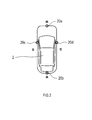
- the vehicle surrounding recognition device 1 is an electronic control device mounted on a vehicle 2. As illustrated in FIG. 1, the vehicle surrounding recognition device 1 is connected to an imaging unit 20 mounted on a vehicle 2.
- the imaging unit 20 includes four cameras 20a, 20b, 20c, and 20d. These cameras 20a to 20d are imaging devices for capturing digital color images (hereinafter, images) represented by the YUV color model.
- the four cameras 20a to 20d can be taken as front camera, rear camera, left camera, and right camera in front of, behind, left, and behind the vehicle 2 so that the surroundings of the vehicle can be photographed without loss And are attached respectively to the right.
- Each of the cameras 20a to 20d is for capturing a range including at least a road surface of a road in front of, behind, to the left of, and to the right of the vehicle 2.
- the attachment positions and postures of the cameras 20a to 20d to the vehicle 2 are preset so that the imaging ranges of the cameras 20a to 20d are as described above.
- the actual mounting positions of the cameras 20a to 20d are adjusted in a manufacturing plant or a maintenance plant based on the set mounting position and posture (in other words, the photographing direction).
- the vehicle surrounding recognition device 1 is an information processing device mainly configured with a CPU, a RAM, a ROM, a semiconductor memory, an input / output interface and the like (not shown).
- the vehicle surrounding recognition device 1 is embodied by, for example, a microcontroller or the like in which functions as a computer system are integrated.
- the function of the vehicle surrounding recognition device 1 is realized by the CPU executing a program stored in a substantial storage medium such as a ROM or a semiconductor memory.
- the number of microcontrollers constituting the vehicle periphery recognition apparatus 1 may be one or more.
- the vehicle surrounding recognition device 1 has a function of recognizing a specific object existing around the vehicle 2 from the images captured by the cameras 20a to 20d.
- a specific object existing around the vehicle 2 from the images captured by the cameras 20a to 20d.
- the white line of the lane marker drawn on the road surface of the road on which the vehicle 2 is traveling is mainly recognized as the specific object.
- the vehicle periphery recognition apparatus 1 may be configured to recognize, for example, a traffic moving object such as a vehicle or a pedestrian or a marking object on a road surface as a specific object other than the lane marker.
- the vehicle surrounding recognition device 1 includes a shadow detection unit 11, a feature point detection unit 12, a shadow edge removal unit 13, and a recognition unit 14 as functional components. Note that the method for realizing these elements constituting the vehicle surrounding recognition device 1 is not limited to software, and some or all of the elements are realized using hardware combining logic circuits, analog circuits, etc. It is also good.
- the vehicle surrounding recognition device 1 has a function of generating a bird's eye view image composed of a viewpoint above the vehicle 2.
- the vehicle periphery recognition apparatus 1 generates a bird's-eye view image by performing viewpoint conversion on the images captured by the cameras 20a to 20d using the attachment positions and postures of the cameras 20a to 20d as camera parameters.
- the camera parameters are obtained by digitizing, for example, the mounting positions of the cameras 20a to 20d in the vehicle 2, and the mounting angles in the front, rear, right, left, and upper and lower three axial directions of the vehicle 2. Then, when the vehicle periphery recognition apparatus 1 performs viewpoint conversion of the images captured by the cameras 20a to 20d, the conversion data set based on the camera parameters is used.
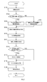
- the vehicle surrounding recognition device 1 acquires a plurality of images captured at the same time by the cameras 20a to 20d, and compares the color tone among the acquired images. Specifically, the vehicle periphery recognition device 1 compares the degree of lightness / lightness of color of pixels distributed in the entire area of a plurality of images captured by the respective cameras 20a to 20d, and the respective cameras 20a to 20d. It is determined whether or not there is a difference in color tone between the images captured by the.
- the vehicle surrounding recognition device 1 branches the process depending on whether or not there is a difference in color tone among the images captured by the cameras 20a to 20d with respect to the result of the process of S100.
- the vehicle periphery recognition device 1 shifts the processing to S104.
- the vehicle surroundings recognition device 1 compares the information of the pixels constituting each image among the images captured by a plurality of different cameras, and the shadow is a shadowed area on the road surface of the road. Detect the area. Specifically, the vehicle periphery recognition device 1 extracts pixels within a predetermined image range corresponding to a range in which the road surface in the vicinity of the vehicle 2 is captured from each of a plurality of different images as a comparison target. And the vehicle periphery recognition apparatus 1 calculates the difference of the intensity
- the blue component in the YUV color model is used for comparison as the specific color component.
- the reason for using the blue component is that due to the influence of Rayleigh scattering, the shaded region tends to have a stronger observation of the blue component than the region illuminated with sunlight.
- the vehicle surrounding recognition device 1 determines that the pixel corresponding to the condition that the luminance is lower than the predetermined threshold by the predetermined threshold and the blue component is higher than the predetermined threshold. It is detected as a pixel corresponding to a shadow on the road surface.
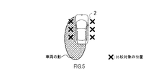
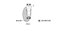
- FIGS. 5 to 9 Specific examples of pixels to be compared for detecting a shadow are shown in FIGS.
- the vehicle periphery recognition device 1 detects a shadow by using the plurality of images in which the left and right regions of the vehicle 2 are captured, and using the pixels to be compared extracted from the left and right lateral regions of the vehicle 2. It represents an example.
- the vehicle periphery recognition device 1 detects a shadow using a plurality of images in which the left and right regions of the vehicle 2 are captured.
- FIG. 6 shows an example in which the vehicle periphery recognition device 1 detects a shadow by using pixels to be compared extracted from neighboring regions before and after the vehicle 2.
- the vehicle periphery recognition device 1 detects a shadow using a plurality of images in which the regions before and after the vehicle 2 are captured.
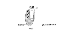
- FIG. 7 shows an example in which the vehicle periphery recognition device 1 detects a shadow with pixels to be compared extracted from the front and left side near regions of the vehicle 2.
- the vehicle periphery recognition device 1 detects a shadow using a plurality of images in which the areas in front of and to the left of the vehicle 2 are captured.
- FIG. 8 shows an example in which the vehicle periphery recognition device 1 detects a shadow using pixels to be compared extracted from the left front and left side near regions of the vehicle 2.
- the vehicle periphery recognition device 1 detects a shadow using a plurality of images in which the left front and left side regions of the vehicle 2 are captured.
- the case of FIG. 8 may be configured to detect a shadow using pixels to be compared extracted from one image in which the left front and left side regions of the vehicle 2 are captured.
- FIG. 9 shows an example in which the vehicle periphery recognition device 1 detects a shadow with pixels to be compared extracted from the rear and right rear neighborhood regions of the vehicle 2.
- the vehicle periphery recognition device 1 detects a shadow using a plurality of images in which the rear and right rear areas of the vehicle 2 are captured.
- the case of FIG. 9 may be configured to detect a shadow using pixels to be compared extracted from one image in which the regions behind and to the right of the vehicle 2 are captured.
- pixels to be compared are extracted from different image regions in the vicinity of the vehicle 2. Shadows can be detected quickly. In addition, when the extension direction of the shadow is known, the shadow can be detected more quickly by comparing pixels in the image in the extension direction of the shadow and the image other than the extension direction of the shadow.
- the vehicle periphery recognition device 1 shifts the processing to S106.
- the vehicle periphery recognition device 1 applies a shadow on the road surface of the road by comparing the information of the comparison target pixel extracted from the same image for each of the images captured by the cameras 20a to 20d.
- the shadow area which is the area covered by
- the color tone may be observed to be different between the plurality of images.
- the vehicle periphery recognition device 1 compares pixel information among pixels extracted from the same image. By doing this, it is possible to suppress a drop in shadow detection accuracy due to a difference in color tone between images.
- the vehicle periphery recognition device 1 extracts pixels in a predetermined image range corresponding to a range in which the road surface in the vicinity of the vehicle 2 is taken from the same image as a comparison target. And the vehicle periphery recognition apparatus 1 calculates the difference of the intensity
- the vehicle periphery recognition device 1 detects a shadow by comparing the luminance and the intensity of the blue component between pixels to be compared extracted from within the same image.
- the vehicle surrounding recognition device 1 detects a shadow by comparing the luminance and the intensity of the blue component between pixels to be compared extracted from within the same image.
- the vehicle surrounding recognition device 1 acquires pixel values representing the luminance and color of the pixel corresponding to the shadow detected on the road surface near the vehicle 2. And the vehicle periphery recognition apparatus 1 detects the shadow area
- the vehicle periphery recognition apparatus 1 unifies the shadow area detected from each image in S104 and S106, and specifies the position of the shadow area in the whole circumference of the vehicle 2.
- the vehicle surrounding recognition device 1 stores, in the memory, feature quantities representing the brightness and the blue component of the shadow detected in S104 and S106.
- the shadow feature can be detected at high speed by using the feature amount of the shadow stored in S110 as a reference for detecting the shadow in the image captured later in the image recognition process from the next time onward.
- the direction in which the shadow extends may be stored and used as a reference for determining the position at which the pixel to be compared is extracted in the image recognition processing from the next time onward.
- the processing of S100 to S110 corresponds to the processing executed by the function of the shadow detection unit 11.
- the vehicle periphery recognition device 1 detects feature points from the images captured by the cameras 20a to 20d. In the present embodiment, for example, a place where the pixel value changes discontinuously in the image is detected as a feature point. In addition, when searching for a feature point in the detected shadow area, the vehicle periphery recognition apparatus 1 may change the threshold of the change in the pixel value to be determined as the feature point from the threshold applied to other areas. .
- the process of S112 corresponds to the process performed by the function of the feature point detection unit 12.
- the vehicle periphery recognition device 1 branches the process depending on whether the shadow area present in the image is detected in the process of S104 or S106. Specifically, if there is a shadow area in the image (S114: YES), the vehicle surroundings recognition device 1 shifts the processing to S116. On the other hand, when there is no shadow area in the image (S114: NO), the vehicle surroundings recognition device 1 skips S116 and shifts the processing to S118.
- the vehicle periphery recognition apparatus 1 removes the feature point applicable to the shadow edge which is a boundary of the shadow area
- the vehicle periphery recognition device 1 has feature points as follows. It may be determined whether or not it corresponds to a shadow edge.
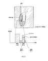
- FIG. 12 shows a situation in which a feature point forming an edge of a white line which is an object in a shadow of a vehicle 2 is detected.
- the pixel value gap is large between the road surface in the shadow and the white line in the shadow, so the feature point is used as the road surface in the shadow and the road surface in the sun May be mistaken as a border with
- the vehicle periphery recognition device 1 confirms the pixel values of the area offset in the width direction of the road by the distance on the image corresponding to the width of the lane marker, for the feature points present in the shadow. Then, the vehicle surrounding recognition device 1 determines whether the feature point is a lane marker in the shadow depending on whether pixel values equivalent to the feature points present in the shadow are distributed in the width of the lane marker, Determine if it is the boundary between the shadow and the sun.
- the vehicle periphery recognition device 1 detects feature points as follows: It may be determined whether or not the image corresponds to a shadow edge.
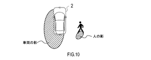
- FIG. 13 shows a situation where a feature point forming a shadow edge is detected between the shadow of the vehicle 2 and a black object.
- the bright road surface around the feature point may be misrecognized as the white line of the lane marker.
- the vehicle periphery recognition device 1 collates the pixel value of the area sandwiched between the shadow and the black object with the pixel value of the road surface of the sun which has been acquired in advance.
- the vehicle periphery recognition apparatus 1 determines the area as the road surface on the sunny side. In this case, the vehicle periphery recognition apparatus 1 removes feature points existing between the shadow and the shadow of the black object as a shadow edge.
- the description will return to the flowchart of FIG.
- the processes of S114 and S116 correspond to the process performed by the function of the shadow edge removing unit 13.
- the vehicle periphery recognition device 1 performs tar reflection removal processing on the feature points on the image remaining after the processing up to S116.
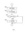
- the procedure of the tar reflection removal process of S118 will be described with reference to the flowchart of FIG.
- the tar reflection removal processing is processing for removing, from the feature point group detected on the image, the feature points caused by the light reflected by the oily stain such as tar existing on the road.
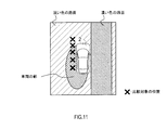
- the vehicle surrounding recognition device 1 estimates the position of the sun based on the direction in which the shadow has already been detected. Specifically, the vehicle periphery recognition device 1 estimates that there is a position where the sun is present on the opposite side of the direction in which the shadow extends.
- the vehicle periphery recognition apparatus 1 estimates the position where reflected light, such as tar, is reflected on the image. Specifically, in the image, the vehicle periphery recognition device 1 reflects light such as tar on a portion showing a luminance equal to or greater than a predetermined threshold in a region corresponding to the road surface between the position of the sun and the vehicle 2.
- the vehicle periphery recognition device 1 branches the process depending on whether or not the reflected light such as tar is present in the image.
- the reflected light such as tar is present in the image (S204: YES)
- the vehicle surroundings recognition apparatus 1 shifts the process to S206.
- the vehicle periphery recognition apparatus 1 removes the feature point applicable to reflected light, such as tar estimated in S202, about the feature point group detected from the image.
- the vehicle surroundings recognition device 1 skips S206 and ends the tar reflection removal process.
- the vehicle periphery recognition apparatus 1 executes an object recognition process of detecting an object corresponding to a specific object based on the feature point group on the image remaining after the process up to S118. Specifically, the vehicle periphery recognition apparatus 1 detects an object such as a lane marker using a known image recognition algorithm using feature points of an image. Further, the vehicle periphery recognition apparatus 1 may be configured to detect not only a lane marker but also a traffic moving object such as a vehicle or a person or an object such as a road marking as an object.
- the process of S120 corresponds to the process executed as the function of the recognition unit 14. Above, the vehicle surrounding recognition apparatus 1 complete
- the vehicle surrounding recognition device 1 determines the shadow area based not only on the luminance of the image but also on the degree of the blue component contained in the color indicated by the image. By doing this, it is possible to improve the robustness to changes in light and dark of an image and to detect a shadow area with high accuracy. Then, the vehicle periphery recognition device 1 can accurately detect the target object by removing the feature points corresponding to the edge of the shadow area from the feature point group detected from within the image.
- the vehicle periphery recognition device 1 can detect a shadow by comparing pixels between different images captured by the plurality of cameras 20a to 20d. By doing this, the shadow can be detected accurately from various directions around the vehicle 2 according to the direction in which the shadow extends.
- the vehicle periphery recognition device 1 detects pixels by comparing pixels among different images.
- the vehicle surrounding recognition device 1 detects pixels by comparing pixels in the same image.
- the vehicle 2 may have at least one camera.
- the vehicle periphery recognition apparatus 1 converts the image captured by the one camera into a bird's-eye view image, or removes the edge of the shadow area detected from the image. Above, detect the object.
- the case of specifying the shadow area using the digital color image represented by the YUV color model has been described.
- the configuration may be such that a shadow area is specified using a digital color image represented by an RGB color model.
- the vehicle surrounding recognition device 1 may be configured to determine only the luminance without performing the determination regarding the blue component of the image. Also, in an environment where a sodium lamp is used as a light source, the yellow component tends to appear strongly in the shadow image. Therefore, when detecting a shadow in an environment where a sodium lamp is used as a light source, the vehicle surrounding recognition device 1 may be configured to make a determination on the degree of the yellow component of the image.
- the vehicle surrounding recognition device 1 may be configured to estimate the heading based on the detected shadow direction and date and time. From the estimated direction, it is possible to estimate an area where tar or the like present on the road surface has a high possibility of reflecting light and strongly emitting light.
- the function possessed by one component in each of the above embodiments may be shared by a plurality of components, or the function possessed by a plurality of components may be exhibited by one component.
- part of the configuration of each of the above embodiments may be omitted.
- at least a part of the configuration of each of the above-described embodiments may be added to or replaced with the configuration of the other above-described embodiments.
- all the aspects contained in the technical thought specified from the wording described in a claim are embodiments of this indication.
- (E) A system having the above-described vehicle surrounding recognition apparatus 1 as a component, a program for causing a computer to function as the vehicle surrounding recognition apparatus 1, a substantial recording medium such as a semiconductor memory storing this program, an object recognition method, etc.
- the present disclosure can be implemented in various forms.
Landscapes
- Engineering & Computer Science (AREA)
- Physics & Mathematics (AREA)
- General Physics & Mathematics (AREA)
- Theoretical Computer Science (AREA)
- Multimedia (AREA)
- Computer Vision & Pattern Recognition (AREA)
- Signal Processing (AREA)
- Image Analysis (AREA)
- Traffic Control Systems (AREA)
- Image Processing (AREA)
Priority Applications (1)
| Application Number | Priority Date | Filing Date | Title |
|---|---|---|---|
| US16/739,472 US11282235B2 (en) | 2017-07-14 | 2020-01-10 | Vehicle surroundings recognition apparatus |
Applications Claiming Priority (2)
| Application Number | Priority Date | Filing Date | Title |
|---|---|---|---|
| JP2017137853A JP6720931B2 (ja) | 2017-07-14 | 2017-07-14 | 車両周囲認識装置 |
| JP2017-137853 | 2017-07-14 |
Related Child Applications (1)
| Application Number | Title | Priority Date | Filing Date |
|---|---|---|---|
| US16/739,472 Continuation US11282235B2 (en) | 2017-07-14 | 2020-01-10 | Vehicle surroundings recognition apparatus |
Publications (1)
| Publication Number | Publication Date |
|---|---|
| WO2019013252A1 true WO2019013252A1 (ja) | 2019-01-17 |
Family
ID=65002005
Family Applications (1)
| Application Number | Title | Priority Date | Filing Date |
|---|---|---|---|
| PCT/JP2018/026190 Ceased WO2019013252A1 (ja) | 2017-07-14 | 2018-07-11 | 車両周囲認識装置 |
Country Status (3)
| Country | Link |
|---|---|
| US (1) | US11282235B2 (enExample) |
| JP (1) | JP6720931B2 (enExample) |
| WO (1) | WO2019013252A1 (enExample) |
Families Citing this family (8)
| Publication number | Priority date | Publication date | Assignee | Title |
|---|---|---|---|---|
| EP3776128B1 (en) * | 2018-03-26 | 2024-02-21 | Jabil Inc. | Apparatus, system, and method of using depth assessment for autonomous robot navigation |
| US10762681B2 (en) | 2018-06-26 | 2020-09-01 | Here Global B.V. | Map generation system and method for generating an accurate building shadow |
| US11164031B2 (en) * | 2018-06-26 | 2021-11-02 | Here Global B.V. | System and method for analyzing an image of a vehicle |
| JP7310527B2 (ja) * | 2019-10-14 | 2023-07-19 | 株式会社デンソー | 障害物識別装置および障害物識別プログラム |
| US11328607B2 (en) * | 2020-03-20 | 2022-05-10 | Aptiv Technologies Limited | System and method of detecting vacant parking spots |
| TWI762365B (zh) * | 2021-06-29 | 2022-04-21 | 晶睿通訊股份有限公司 | 影像辨識方法及其影像監控設備 |
| KR20240048533A (ko) * | 2021-08-19 | 2024-04-15 | 테슬라, 인크. | 시뮬레이션 콘텐트를 사용한 비전 기반 시스템 훈련 |
| US12462575B2 (en) | 2021-08-19 | 2025-11-04 | Tesla, Inc. | Vision-based machine learning model for autonomous driving with adjustable virtual camera |
Citations (4)
| Publication number | Priority date | Publication date | Assignee | Title |
|---|---|---|---|---|
| JP2009031939A (ja) * | 2007-07-25 | 2009-02-12 | Advanced Telecommunication Research Institute International | 画像処理装置、画像処理方法及び画像処理プログラム |
| JP4270183B2 (ja) * | 2005-08-22 | 2009-05-27 | トヨタ自動車株式会社 | 白線検出装置 |
| JP2010237976A (ja) * | 2009-03-31 | 2010-10-21 | Kyushu Institute Of Technology | 光源情報取得装置、陰影検出装置、陰影除去装置、それらの方法、及びプログラム |
| JP2014035561A (ja) * | 2012-08-07 | 2014-02-24 | Nissan Motor Co Ltd | 車両走行支援装置及び車両走行支援方法 |
Family Cites Families (8)
| Publication number | Priority date | Publication date | Assignee | Title |
|---|---|---|---|---|
| JP3083918B2 (ja) * | 1992-06-26 | 2000-09-04 | 本田技研工業株式会社 | 画像処理装置 |
| JP3463858B2 (ja) * | 1998-08-27 | 2003-11-05 | 矢崎総業株式会社 | 周辺監視装置及び方法 |
| US7184890B2 (en) * | 2003-11-24 | 2007-02-27 | The Boeing Company | Cloud shadow detection: VNIR-SWIR |
| CN101833749B (zh) * | 2009-03-12 | 2012-03-28 | 株式会社理光 | 检测图像中阴影的装置和方法 |
| EP2287807A1 (en) * | 2009-07-21 | 2011-02-23 | Nikon Corporation | Image processing device, image processing program, and imaging device |
| JP5066558B2 (ja) | 2009-09-17 | 2012-11-07 | 日立オートモティブシステムズ株式会社 | 自車影認識装置 |
| JP6003226B2 (ja) * | 2012-05-23 | 2016-10-05 | 株式会社デンソー | 車両周囲画像表示制御装置および車両周囲画像表示制御プログラム |
| US9430715B1 (en) * | 2015-05-01 | 2016-08-30 | Adobe Systems Incorporated | Identifying and modifying cast shadows in an image |
-
2017
- 2017-07-14 JP JP2017137853A patent/JP6720931B2/ja active Active
-
2018
- 2018-07-11 WO PCT/JP2018/026190 patent/WO2019013252A1/ja not_active Ceased
-
2020
- 2020-01-10 US US16/739,472 patent/US11282235B2/en active Active
Patent Citations (4)
| Publication number | Priority date | Publication date | Assignee | Title |
|---|---|---|---|---|
| JP4270183B2 (ja) * | 2005-08-22 | 2009-05-27 | トヨタ自動車株式会社 | 白線検出装置 |
| JP2009031939A (ja) * | 2007-07-25 | 2009-02-12 | Advanced Telecommunication Research Institute International | 画像処理装置、画像処理方法及び画像処理プログラム |
| JP2010237976A (ja) * | 2009-03-31 | 2010-10-21 | Kyushu Institute Of Technology | 光源情報取得装置、陰影検出装置、陰影除去装置、それらの方法、及びプログラム |
| JP2014035561A (ja) * | 2012-08-07 | 2014-02-24 | Nissan Motor Co Ltd | 車両走行支援装置及び車両走行支援方法 |
Also Published As
| Publication number | Publication date |
|---|---|
| JP2019020956A (ja) | 2019-02-07 |
| JP6720931B2 (ja) | 2020-07-08 |
| US11282235B2 (en) | 2022-03-22 |
| US20200151912A1 (en) | 2020-05-14 |
Similar Documents
| Publication | Publication Date | Title |
|---|---|---|
| WO2019013252A1 (ja) | 車両周囲認識装置 | |
| US8319854B2 (en) | Shadow removal in an image captured by a vehicle based camera using a non-linear illumination-invariant kernel | |
| US8036427B2 (en) | Vehicle and road sign recognition device | |
| US8345100B2 (en) | Shadow removal in an image captured by a vehicle-based camera using an optimized oriented linear axis | |
| US20160350603A1 (en) | Lane detection | |
| CN103679733B (zh) | 一种信号灯图像处理方法及其装置 | |
| CN110619750A (zh) | 面向违停车辆的智能航拍识别方法及系统 | |
| JP6413318B2 (ja) | 車両検出装置、およびシステム、ならびにプログラム | |
| CN111046741A (zh) | 车道线识别的方法和装置 | |
| WO2018008461A1 (ja) | 画像処理装置 | |
| JP6375911B2 (ja) | カーブミラー検出装置 | |
| JP7230507B2 (ja) | 付着物検出装置 | |
| EP1887522B1 (en) | Vehicle and road sign recognition device | |
| KR101402089B1 (ko) | 장애물 검출 장치 및 방법 | |
| KR101026778B1 (ko) | 차량 영상 검지 장치 | |
| JP2011209896A (ja) | 障害物検知装置、障害物検知方法及び障害物検知プログラム | |
| JP5338762B2 (ja) | ホワイトバランス係数算出装置及びプログラム | |
| JP7200893B2 (ja) | 付着物検出装置および付着物検出方法 | |
| JP4941843B2 (ja) | 路面標示画像処理装置、路面標示画像処理方法並びに路面標示画像処理プログラム | |
| JP2015061163A (ja) | 遮蔽検知装置 | |
| CN113632450B (zh) | 摄影系统及图像处理装置 | |
| JP5862217B2 (ja) | マーカの検出および追跡装置 | |
| US10997743B2 (en) | Attachable matter detection apparatus | |
| KR101875786B1 (ko) | 도로영상에서 후미등영역을 이용한 차량식별방법 | |
| JPH1166490A (ja) | 車両検出方法 |
Legal Events
| Date | Code | Title | Description |
|---|---|---|---|
| 121 | Ep: the epo has been informed by wipo that ep was designated in this application |
Ref document number: 18832050 Country of ref document: EP Kind code of ref document: A1 |
|
| NENP | Non-entry into the national phase |
Ref country code: DE |
|
| 122 | Ep: pct application non-entry in european phase |
Ref document number: 18832050 Country of ref document: EP Kind code of ref document: A1 |