WO2019013252A1 - Vehicle surroundings recognition device - Google Patents
Vehicle surroundings recognition device Download PDFInfo
- Publication number
- WO2019013252A1 WO2019013252A1 PCT/JP2018/026190 JP2018026190W WO2019013252A1 WO 2019013252 A1 WO2019013252 A1 WO 2019013252A1 JP 2018026190 W JP2018026190 W JP 2018026190W WO 2019013252 A1 WO2019013252 A1 WO 2019013252A1
- Authority
- WO
- WIPO (PCT)
- Prior art keywords
- shadow
- image
- vehicle
- recognition device
- detection unit
- Prior art date
Links
Images


Classifications
-
- G—PHYSICS
- G06—COMPUTING; CALCULATING OR COUNTING
- G06T—IMAGE DATA PROCESSING OR GENERATION, IN GENERAL
- G06T7/00—Image analysis
- G06T7/70—Determining position or orientation of objects or cameras
- G06T7/73—Determining position or orientation of objects or cameras using feature-based methods
-
- G—PHYSICS
- G06—COMPUTING; CALCULATING OR COUNTING
- G06T—IMAGE DATA PROCESSING OR GENERATION, IN GENERAL
- G06T7/00—Image analysis
- G06T7/90—Determination of colour characteristics
-
- G—PHYSICS
- G06—COMPUTING; CALCULATING OR COUNTING
- G06T—IMAGE DATA PROCESSING OR GENERATION, IN GENERAL
- G06T7/00—Image analysis
- G06T7/97—Determining parameters from multiple pictures
-
- G—PHYSICS
- G06—COMPUTING; CALCULATING OR COUNTING
- G06V—IMAGE OR VIDEO RECOGNITION OR UNDERSTANDING
- G06V10/00—Arrangements for image or video recognition or understanding
- G06V10/40—Extraction of image or video features
- G06V10/56—Extraction of image or video features relating to colour
-
- G—PHYSICS
- G06—COMPUTING; CALCULATING OR COUNTING
- G06V—IMAGE OR VIDEO RECOGNITION OR UNDERSTANDING
- G06V20/00—Scenes; Scene-specific elements
- G06V20/50—Context or environment of the image
- G06V20/56—Context or environment of the image exterior to a vehicle by using sensors mounted on the vehicle
- G06V20/588—Recognition of the road, e.g. of lane markings; Recognition of the vehicle driving pattern in relation to the road
-
- H—ELECTRICITY
- H04—ELECTRIC COMMUNICATION TECHNIQUE
- H04N—PICTORIAL COMMUNICATION, e.g. TELEVISION
- H04N23/00—Cameras or camera modules comprising electronic image sensors; Control thereof
- H04N23/60—Control of cameras or camera modules
- H04N23/698—Control of cameras or camera modules for achieving an enlarged field of view, e.g. panoramic image capture
-
- G—PHYSICS
- G06—COMPUTING; CALCULATING OR COUNTING
- G06T—IMAGE DATA PROCESSING OR GENERATION, IN GENERAL
- G06T2207/00—Indexing scheme for image analysis or image enhancement
- G06T2207/10—Image acquisition modality
- G06T2207/10024—Color image
-
- G—PHYSICS
- G06—COMPUTING; CALCULATING OR COUNTING
- G06T—IMAGE DATA PROCESSING OR GENERATION, IN GENERAL
- G06T2207/00—Indexing scheme for image analysis or image enhancement
- G06T2207/30—Subject of image; Context of image processing
- G06T2207/30248—Vehicle exterior or interior
- G06T2207/30252—Vehicle exterior; Vicinity of vehicle
- G06T2207/30256—Lane; Road marking
-
- H—ELECTRICITY
- H04—ELECTRIC COMMUNICATION TECHNIQUE
- H04N—PICTORIAL COMMUNICATION, e.g. TELEVISION
- H04N23/00—Cameras or camera modules comprising electronic image sensors; Control thereof
- H04N23/90—Arrangement of cameras or camera modules, e.g. multiple cameras in TV studios or sports stadiums
Definitions
- the present disclosure relates to a vehicle periphery recognition apparatus that recognizes an object from an image obtained by imaging a road around a vehicle.
- Patent Document 1 describes a prior art related to a white line detection device for detecting a white line drawn on a road based on an image obtained by photographing the road.
- the white line detection apparatus is configured to set a shadow area based on a change in light and dark of an image and to detect a white line after erasing an edge of the shadow area. According to the prior art, when there is a shadow of the vehicle, a building, or the like on the road surface of the road, a decrease in the white line detection accuracy is suppressed.
- the white line detection device estimates a shadow area from among the detected edges based only on the change in brightness of the image. Therefore, the white line detection apparatus may erroneously recognize a change in light and shade that is not originally a shadow as a shadow.
- a vehicle surrounding recognition device capable of improving the detection accuracy of an object by accurately detecting a shadow that is on a road surface of a road.
- a vehicle surrounding recognition device acquires an image captured by an imaging unit.
- the imaging unit is mounted on the vehicle so as to image a range including a road around the vehicle.
- a vehicle periphery recognition apparatus recognizes the specific target object which exists around the vehicle from the acquired image.
- the vehicle surrounding recognition device includes a shadow detection unit, a feature point detection unit, and a recognition unit.
- the shadow detection unit is configured to detect a shadow area based on the difference between the degree of a specific color component included in the color represented by each element and the luminance among a plurality of elements constituting an image. It is done.
- the shadow area is an area that is shaded on the road surface in the image.
- the feature point detection unit is configured to detect a feature point from the image.
- the recognition unit is configured to recognize an object based on the detected shadow area and feature point group.
- the shadow area is characterized in that the blue component is stronger than the sunlit area. It was done.
- This feature is due to the effect of Rayleigh scattering. That is, in the area illuminated by sunlight and the shadow area in the image, in addition to the change in light and dark, a change is observed for a specific color component. So, in the vehicle periphery recognition apparatus which concerns on this indication, a shadow area
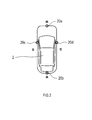
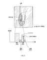
- the vehicle surrounding recognition device 1 is an electronic control device mounted on a vehicle 2. As illustrated in FIG. 1, the vehicle surrounding recognition device 1 is connected to an imaging unit 20 mounted on a vehicle 2.
- the imaging unit 20 includes four cameras 20a, 20b, 20c, and 20d. These cameras 20a to 20d are imaging devices for capturing digital color images (hereinafter, images) represented by the YUV color model.
- the four cameras 20a to 20d can be taken as front camera, rear camera, left camera, and right camera in front of, behind, left, and behind the vehicle 2 so that the surroundings of the vehicle can be photographed without loss And are attached respectively to the right.
- Each of the cameras 20a to 20d is for capturing a range including at least a road surface of a road in front of, behind, to the left of, and to the right of the vehicle 2.
- the attachment positions and postures of the cameras 20a to 20d to the vehicle 2 are preset so that the imaging ranges of the cameras 20a to 20d are as described above.
- the actual mounting positions of the cameras 20a to 20d are adjusted in a manufacturing plant or a maintenance plant based on the set mounting position and posture (in other words, the photographing direction).
- the vehicle surrounding recognition device 1 is an information processing device mainly configured with a CPU, a RAM, a ROM, a semiconductor memory, an input / output interface and the like (not shown).
- the vehicle surrounding recognition device 1 is embodied by, for example, a microcontroller or the like in which functions as a computer system are integrated.
- the function of the vehicle surrounding recognition device 1 is realized by the CPU executing a program stored in a substantial storage medium such as a ROM or a semiconductor memory.
- the number of microcontrollers constituting the vehicle periphery recognition apparatus 1 may be one or more.
- the vehicle surrounding recognition device 1 has a function of recognizing a specific object existing around the vehicle 2 from the images captured by the cameras 20a to 20d.
- a specific object existing around the vehicle 2 from the images captured by the cameras 20a to 20d.
- the white line of the lane marker drawn on the road surface of the road on which the vehicle 2 is traveling is mainly recognized as the specific object.
- the vehicle periphery recognition apparatus 1 may be configured to recognize, for example, a traffic moving object such as a vehicle or a pedestrian or a marking object on a road surface as a specific object other than the lane marker.
- the vehicle surrounding recognition device 1 includes a shadow detection unit 11, a feature point detection unit 12, a shadow edge removal unit 13, and a recognition unit 14 as functional components. Note that the method for realizing these elements constituting the vehicle surrounding recognition device 1 is not limited to software, and some or all of the elements are realized using hardware combining logic circuits, analog circuits, etc. It is also good.
- the vehicle surrounding recognition device 1 has a function of generating a bird's eye view image composed of a viewpoint above the vehicle 2.
- the vehicle periphery recognition apparatus 1 generates a bird's-eye view image by performing viewpoint conversion on the images captured by the cameras 20a to 20d using the attachment positions and postures of the cameras 20a to 20d as camera parameters.
- the camera parameters are obtained by digitizing, for example, the mounting positions of the cameras 20a to 20d in the vehicle 2, and the mounting angles in the front, rear, right, left, and upper and lower three axial directions of the vehicle 2. Then, when the vehicle periphery recognition apparatus 1 performs viewpoint conversion of the images captured by the cameras 20a to 20d, the conversion data set based on the camera parameters is used.
- the vehicle surrounding recognition device 1 acquires a plurality of images captured at the same time by the cameras 20a to 20d, and compares the color tone among the acquired images. Specifically, the vehicle periphery recognition device 1 compares the degree of lightness / lightness of color of pixels distributed in the entire area of a plurality of images captured by the respective cameras 20a to 20d, and the respective cameras 20a to 20d. It is determined whether or not there is a difference in color tone between the images captured by the.
- the vehicle surrounding recognition device 1 branches the process depending on whether or not there is a difference in color tone among the images captured by the cameras 20a to 20d with respect to the result of the process of S100.
- the vehicle periphery recognition device 1 shifts the processing to S104.
- the vehicle surroundings recognition device 1 compares the information of the pixels constituting each image among the images captured by a plurality of different cameras, and the shadow is a shadowed area on the road surface of the road. Detect the area. Specifically, the vehicle periphery recognition device 1 extracts pixels within a predetermined image range corresponding to a range in which the road surface in the vicinity of the vehicle 2 is captured from each of a plurality of different images as a comparison target. And the vehicle periphery recognition apparatus 1 calculates the difference of the intensity
- the blue component in the YUV color model is used for comparison as the specific color component.
- the reason for using the blue component is that due to the influence of Rayleigh scattering, the shaded region tends to have a stronger observation of the blue component than the region illuminated with sunlight.
- the vehicle surrounding recognition device 1 determines that the pixel corresponding to the condition that the luminance is lower than the predetermined threshold by the predetermined threshold and the blue component is higher than the predetermined threshold. It is detected as a pixel corresponding to a shadow on the road surface.
- FIGS. 5 to 9 Specific examples of pixels to be compared for detecting a shadow are shown in FIGS.
- the vehicle periphery recognition device 1 detects a shadow by using the plurality of images in which the left and right regions of the vehicle 2 are captured, and using the pixels to be compared extracted from the left and right lateral regions of the vehicle 2. It represents an example.
- the vehicle periphery recognition device 1 detects a shadow using a plurality of images in which the left and right regions of the vehicle 2 are captured.
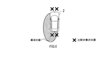
- FIG. 6 shows an example in which the vehicle periphery recognition device 1 detects a shadow by using pixels to be compared extracted from neighboring regions before and after the vehicle 2.
- the vehicle periphery recognition device 1 detects a shadow using a plurality of images in which the regions before and after the vehicle 2 are captured.
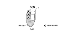
- FIG. 7 shows an example in which the vehicle periphery recognition device 1 detects a shadow with pixels to be compared extracted from the front and left side near regions of the vehicle 2.
- the vehicle periphery recognition device 1 detects a shadow using a plurality of images in which the areas in front of and to the left of the vehicle 2 are captured.
- FIG. 8 shows an example in which the vehicle periphery recognition device 1 detects a shadow using pixels to be compared extracted from the left front and left side near regions of the vehicle 2.
- the vehicle periphery recognition device 1 detects a shadow using a plurality of images in which the left front and left side regions of the vehicle 2 are captured.
- the case of FIG. 8 may be configured to detect a shadow using pixels to be compared extracted from one image in which the left front and left side regions of the vehicle 2 are captured.
- FIG. 9 shows an example in which the vehicle periphery recognition device 1 detects a shadow with pixels to be compared extracted from the rear and right rear neighborhood regions of the vehicle 2.
- the vehicle periphery recognition device 1 detects a shadow using a plurality of images in which the rear and right rear areas of the vehicle 2 are captured.
- the case of FIG. 9 may be configured to detect a shadow using pixels to be compared extracted from one image in which the regions behind and to the right of the vehicle 2 are captured.
- pixels to be compared are extracted from different image regions in the vicinity of the vehicle 2. Shadows can be detected quickly. In addition, when the extension direction of the shadow is known, the shadow can be detected more quickly by comparing pixels in the image in the extension direction of the shadow and the image other than the extension direction of the shadow.
- the vehicle periphery recognition device 1 shifts the processing to S106.
- the vehicle periphery recognition device 1 applies a shadow on the road surface of the road by comparing the information of the comparison target pixel extracted from the same image for each of the images captured by the cameras 20a to 20d.
- the shadow area which is the area covered by
- the color tone may be observed to be different between the plurality of images.
- the vehicle periphery recognition device 1 compares pixel information among pixels extracted from the same image. By doing this, it is possible to suppress a drop in shadow detection accuracy due to a difference in color tone between images.
- the vehicle periphery recognition device 1 extracts pixels in a predetermined image range corresponding to a range in which the road surface in the vicinity of the vehicle 2 is taken from the same image as a comparison target. And the vehicle periphery recognition apparatus 1 calculates the difference of the intensity
- the vehicle periphery recognition device 1 detects a shadow by comparing the luminance and the intensity of the blue component between pixels to be compared extracted from within the same image.
- the vehicle surrounding recognition device 1 detects a shadow by comparing the luminance and the intensity of the blue component between pixels to be compared extracted from within the same image.
- the vehicle surrounding recognition device 1 acquires pixel values representing the luminance and color of the pixel corresponding to the shadow detected on the road surface near the vehicle 2. And the vehicle periphery recognition apparatus 1 detects the shadow area
- the vehicle periphery recognition apparatus 1 unifies the shadow area detected from each image in S104 and S106, and specifies the position of the shadow area in the whole circumference of the vehicle 2.
- the vehicle surrounding recognition device 1 stores, in the memory, feature quantities representing the brightness and the blue component of the shadow detected in S104 and S106.
- the shadow feature can be detected at high speed by using the feature amount of the shadow stored in S110 as a reference for detecting the shadow in the image captured later in the image recognition process from the next time onward.
- the direction in which the shadow extends may be stored and used as a reference for determining the position at which the pixel to be compared is extracted in the image recognition processing from the next time onward.
- the processing of S100 to S110 corresponds to the processing executed by the function of the shadow detection unit 11.
- the vehicle periphery recognition device 1 detects feature points from the images captured by the cameras 20a to 20d. In the present embodiment, for example, a place where the pixel value changes discontinuously in the image is detected as a feature point. In addition, when searching for a feature point in the detected shadow area, the vehicle periphery recognition apparatus 1 may change the threshold of the change in the pixel value to be determined as the feature point from the threshold applied to other areas. .
- the process of S112 corresponds to the process performed by the function of the feature point detection unit 12.
- the vehicle periphery recognition device 1 branches the process depending on whether the shadow area present in the image is detected in the process of S104 or S106. Specifically, if there is a shadow area in the image (S114: YES), the vehicle surroundings recognition device 1 shifts the processing to S116. On the other hand, when there is no shadow area in the image (S114: NO), the vehicle surroundings recognition device 1 skips S116 and shifts the processing to S118.
- the vehicle periphery recognition apparatus 1 removes the feature point applicable to the shadow edge which is a boundary of the shadow area
- the vehicle periphery recognition device 1 has feature points as follows. It may be determined whether or not it corresponds to a shadow edge.
- FIG. 12 shows a situation in which a feature point forming an edge of a white line which is an object in a shadow of a vehicle 2 is detected.
- the pixel value gap is large between the road surface in the shadow and the white line in the shadow, so the feature point is used as the road surface in the shadow and the road surface in the sun May be mistaken as a border with
- the vehicle periphery recognition device 1 confirms the pixel values of the area offset in the width direction of the road by the distance on the image corresponding to the width of the lane marker, for the feature points present in the shadow. Then, the vehicle surrounding recognition device 1 determines whether the feature point is a lane marker in the shadow depending on whether pixel values equivalent to the feature points present in the shadow are distributed in the width of the lane marker, Determine if it is the boundary between the shadow and the sun.
- the vehicle periphery recognition device 1 detects feature points as follows: It may be determined whether or not the image corresponds to a shadow edge.
- FIG. 13 shows a situation where a feature point forming a shadow edge is detected between the shadow of the vehicle 2 and a black object.
- the bright road surface around the feature point may be misrecognized as the white line of the lane marker.
- the vehicle periphery recognition device 1 collates the pixel value of the area sandwiched between the shadow and the black object with the pixel value of the road surface of the sun which has been acquired in advance.
- the vehicle periphery recognition apparatus 1 determines the area as the road surface on the sunny side. In this case, the vehicle periphery recognition apparatus 1 removes feature points existing between the shadow and the shadow of the black object as a shadow edge.
- the description will return to the flowchart of FIG.
- the processes of S114 and S116 correspond to the process performed by the function of the shadow edge removing unit 13.
- the vehicle periphery recognition device 1 performs tar reflection removal processing on the feature points on the image remaining after the processing up to S116.
- the procedure of the tar reflection removal process of S118 will be described with reference to the flowchart of FIG.
- the tar reflection removal processing is processing for removing, from the feature point group detected on the image, the feature points caused by the light reflected by the oily stain such as tar existing on the road.
- the vehicle surrounding recognition device 1 estimates the position of the sun based on the direction in which the shadow has already been detected. Specifically, the vehicle periphery recognition device 1 estimates that there is a position where the sun is present on the opposite side of the direction in which the shadow extends.
- the vehicle periphery recognition apparatus 1 estimates the position where reflected light, such as tar, is reflected on the image. Specifically, in the image, the vehicle periphery recognition device 1 reflects light such as tar on a portion showing a luminance equal to or greater than a predetermined threshold in a region corresponding to the road surface between the position of the sun and the vehicle 2.
- the vehicle periphery recognition device 1 branches the process depending on whether or not the reflected light such as tar is present in the image.
- the reflected light such as tar is present in the image (S204: YES)
- the vehicle surroundings recognition apparatus 1 shifts the process to S206.
- the vehicle periphery recognition apparatus 1 removes the feature point applicable to reflected light, such as tar estimated in S202, about the feature point group detected from the image.
- the vehicle surroundings recognition device 1 skips S206 and ends the tar reflection removal process.
- the vehicle periphery recognition apparatus 1 executes an object recognition process of detecting an object corresponding to a specific object based on the feature point group on the image remaining after the process up to S118. Specifically, the vehicle periphery recognition apparatus 1 detects an object such as a lane marker using a known image recognition algorithm using feature points of an image. Further, the vehicle periphery recognition apparatus 1 may be configured to detect not only a lane marker but also a traffic moving object such as a vehicle or a person or an object such as a road marking as an object.
- the process of S120 corresponds to the process executed as the function of the recognition unit 14. Above, the vehicle surrounding recognition apparatus 1 complete
- the vehicle surrounding recognition device 1 determines the shadow area based not only on the luminance of the image but also on the degree of the blue component contained in the color indicated by the image. By doing this, it is possible to improve the robustness to changes in light and dark of an image and to detect a shadow area with high accuracy. Then, the vehicle periphery recognition device 1 can accurately detect the target object by removing the feature points corresponding to the edge of the shadow area from the feature point group detected from within the image.
- the vehicle periphery recognition device 1 can detect a shadow by comparing pixels between different images captured by the plurality of cameras 20a to 20d. By doing this, the shadow can be detected accurately from various directions around the vehicle 2 according to the direction in which the shadow extends.
- the vehicle periphery recognition device 1 detects pixels by comparing pixels among different images.
- the vehicle surrounding recognition device 1 detects pixels by comparing pixels in the same image.
- the vehicle 2 may have at least one camera.
- the vehicle periphery recognition apparatus 1 converts the image captured by the one camera into a bird's-eye view image, or removes the edge of the shadow area detected from the image. Above, detect the object.
- the case of specifying the shadow area using the digital color image represented by the YUV color model has been described.
- the configuration may be such that a shadow area is specified using a digital color image represented by an RGB color model.
- the vehicle surrounding recognition device 1 may be configured to determine only the luminance without performing the determination regarding the blue component of the image. Also, in an environment where a sodium lamp is used as a light source, the yellow component tends to appear strongly in the shadow image. Therefore, when detecting a shadow in an environment where a sodium lamp is used as a light source, the vehicle surrounding recognition device 1 may be configured to make a determination on the degree of the yellow component of the image.
- the vehicle surrounding recognition device 1 may be configured to estimate the heading based on the detected shadow direction and date and time. From the estimated direction, it is possible to estimate an area where tar or the like present on the road surface has a high possibility of reflecting light and strongly emitting light.
- the function possessed by one component in each of the above embodiments may be shared by a plurality of components, or the function possessed by a plurality of components may be exhibited by one component.
- part of the configuration of each of the above embodiments may be omitted.
- at least a part of the configuration of each of the above-described embodiments may be added to or replaced with the configuration of the other above-described embodiments.
- all the aspects contained in the technical thought specified from the wording described in a claim are embodiments of this indication.
- (E) A system having the above-described vehicle surrounding recognition apparatus 1 as a component, a program for causing a computer to function as the vehicle surrounding recognition apparatus 1, a substantial recording medium such as a semiconductor memory storing this program, an object recognition method, etc.
- the present disclosure can be implemented in various forms.
Abstract
A vehicle surroundings recognition device (1) acquires an image captured by means of an image capture unit (20). A photography unit (20) is mounted on a vehicle (2) so as to capture an image of an area including a road around the vehicle. A shadow detection unit (11), on the basis of differences based on a comparison, between a plurality of elements configuring the image, of the degree of a specific color component and brightness included in the color represented by each element, detects a shadow region from the image which is a region in which a shadow is on the surface of the road. A feature point detection unit (12) detects a feature point from the image. A shadow edge removal unit (13) removes, from a group of detected feature points, a feature point corresponding to an edge of the shadow region. A recognition unit (14) recognizes, from the feature point group after the edge of the shadow region has been removed, a specific object that exists around the vehicle.
Description
本国際出願は、2017年7月14日に日本国特許庁に出願された日本国特許出願第2017-137853号に基づく優先権を主張するものであり、日本国特許出願第2017-137853号の全内容を本国際出願に参照により援用する。
This international application claims priority based on Japanese Patent Application No. 2017-137853 filed with the Japanese Patent Office on July 14, 2017, and the international patent application nos. The entire contents are incorporated by reference into this international application.
本開示は、車両の周囲の道路を撮像した画像から対象物を認識する車両周囲認識装置に関する。
The present disclosure relates to a vehicle periphery recognition apparatus that recognizes an object from an image obtained by imaging a road around a vehicle.
特許文献1には、道路を撮影した画像に基づいて道路に引かれた白線を検出する白線検出装置に関する先行技術が記載されている。この白線検出装置は、画像の明暗の変化に基づいて影領域を設定し、影領域のエッジを消去した後に、白線の検出を行うように構成されている。前記先行技術によれば、道路の路面上に自車両や建物等の影がある場合において、白線の検出精度の低下が抑制される。
Patent Document 1 describes a prior art related to a white line detection device for detecting a white line drawn on a road based on an image obtained by photographing the road. The white line detection apparatus is configured to set a shadow area based on a change in light and dark of an image and to detect a white line after erasing an edge of the shadow area. According to the prior art, when there is a shadow of the vehicle, a building, or the like on the road surface of the road, a decrease in the white line detection accuracy is suppressed.
しかしながら、上述の先行技術においては、白線検出装置は、画像の明暗の変化のみに基づいて検出したエッジの中から影領域を推定する。そため、白線検出装置は、本来は影ではない明暗の変化を影であると誤認識する可能性がある。
However, in the above-described prior art, the white line detection device estimates a shadow area from among the detected edges based only on the change in brightness of the image. Therefore, the white line detection apparatus may erroneously recognize a change in light and shade that is not originally a shadow as a shadow.
そこで、本開示の一局面は、道路の路面上にかかっている影を的確に検出することによって、対象物の検出精度を向上できる車両周囲認識装置を提供することが好ましい。
本開示の一態様に係る車両周囲認識装置は、撮像部により撮像された画像を取得する。撮影部は、車両の周囲の道路を含む範囲を撮像するように当該車両に搭載されている。そして、車両周囲認識装置は、取得された画像から車両の周囲に存在する特定の対象物を認識する。車両周囲認識装置は、影検出部と、特徴点検出部と、認識部とを備える。 Therefore, according to one aspect of the present disclosure, it is preferable to provide a vehicle periphery recognition device capable of improving the detection accuracy of an object by accurately detecting a shadow that is on a road surface of a road.
A vehicle surrounding recognition device according to an aspect of the present disclosure acquires an image captured by an imaging unit. The imaging unit is mounted on the vehicle so as to image a range including a road around the vehicle. And a vehicle periphery recognition apparatus recognizes the specific target object which exists around the vehicle from the acquired image. The vehicle surrounding recognition device includes a shadow detection unit, a feature point detection unit, and a recognition unit.
影検出部は、画像を構成する複数の要素の間で、各要素が表す色に含まれる特定の色成分の度合、及び輝度をそれぞれ比較した差分に基づいて、影領域を検出するように構成されている。影領域は、画像において道路の路面上に影がかかっている領域である。特徴点検出部は、画像の中から特徴点を検出するように構成されている。認識部は、検出された影領域及び特徴点群に基づいて、対象物を認識するように構成されている。
The shadow detection unit is configured to detect a shadow area based on the difference between the degree of a specific color component included in the color represented by each element and the luminance among a plurality of elements constituting an image. It is done. The shadow area is an area that is shaded on the road surface in the image. The feature point detection unit is configured to detect a feature point from the image. The recognition unit is configured to recognize an object based on the detected shadow area and feature point group.
発明者らの検討により、太陽光で照らされた領域と影の領域とで画像の色を比較した場合、影の領域は太陽光で照らされた領域よりも青色成分が強いという特徴が見出された。この特徴は、レイリー散乱の影響によるものである。つまり、画像中における太陽光で照らされた領域と影の領域では、明暗の変化に加えて特定の色成分について変化が観測される。そこで、本開示に係る車両周囲認識装置では、画像の輝度だけでなく、特定の色成分の度合に基づいて影領域を判定する。そのような判定を行うことで、画像の明暗の変化に対するロバスト性を向上させ、影領域を精度よく検出することができる。そして、検出された影領域を加味して対象物の検出を行うことで、目的とする対象物を的確に検出できる。
According to the inventors' investigation, when comparing the color of the image between the sunlit area and the shadow area, it is found that the shadow area is characterized in that the blue component is stronger than the sunlit area. It was done. This feature is due to the effect of Rayleigh scattering. That is, in the area illuminated by sunlight and the shadow area in the image, in addition to the change in light and dark, a change is observed for a specific color component. So, in the vehicle periphery recognition apparatus which concerns on this indication, a shadow area | region is determined not only based on the brightness | luminance of an image but the degree of a specific color component. By performing such a determination, robustness to changes in light and dark of an image can be improved, and shadow areas can be detected with high accuracy. Then, by detecting the object in consideration of the detected shadow area, it is possible to accurately detect the target object.
本開示についての上記目的及びその他の目的、特徴や利点は、添付の図面を参照しながら下記の詳細な記述により、より明確になる。その図面の概要は次のとおりである。
実施形態の車両周囲認識装置の構成を表すブロック図である。
車両におけるカメラの搭載位置の一例を表す説明図。
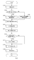
車両周囲認識装置が実行する画像認識処理の手順を表すフローチャートである。
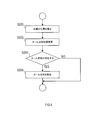
車両周囲認識装置が実行するタール反射除去処理の手順を表すフローチャートである。
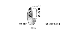
影領域の検出方法の一例を表す説明図である。
影領域の検出方法の一例を表す説明図である。
影領域の検出方法の一例を表す説明図である。
影領域の検出方法の一例を表す説明図である。
影領域の検出方法の一例を表す説明図である。
影領域の検出方法の一例を表す説明図である。
影領域の検出方法の一例を表す説明図である。
白線の認識方法の一例を表す説明図である。
白線の誤認識を抑制する方法の一例を表す説明図である。
The above object and other objects, features and advantages of the present disclosure will become more apparent from the following detailed description with reference to the attached drawings. The outline of the drawing is as follows.
It is a block diagram showing composition of a vehicle circumference recognition device of an embodiment. Explanatory drawing showing an example of the mounting position of the camera in a vehicle. It is a flowchart showing the procedure of the image recognition process which a vehicle periphery recognition apparatus performs. It is a flowchart showing the procedure of the tar reflection removal process which a vehicle periphery recognition apparatus performs. It is explanatory drawing showing an example of the detection method of a shadow area | region. It is explanatory drawing showing an example of the detection method of a shadow area | region. It is explanatory drawing showing an example of the detection method of a shadow area | region. It is explanatory drawing showing an example of the detection method of a shadow area | region. It is explanatory drawing showing an example of the detection method of a shadow area | region. It is explanatory drawing showing an example of the detection method of a shadow area | region. It is explanatory drawing showing an example of the detection method of a shadow area | region. It is explanatory drawing showing an example of the recognition method of a white line. It is explanatory drawing showing an example of the method of suppressing misrecognition of a white line.
以下、本開示の実施形態を図面に基づいて説明する。なお、本開示は下記の実施形態に限定されるものではなく様々な態様にて実施することが可能である。
[車両周囲認識装置の構成の説明]
実施形態の車両周囲認識装置1は、車両2に搭載される電子制御装置である。図1に例示されるとおり、車両周囲認識装置1は、車両2に搭載された撮像部20と接続されている。撮像部20は、4台のカメラ20a,20b,20c,20dを含む。これらのカメラ20a~20dは、YUVカラーモデルで表現されるデジタルカラー画像(以下、画像)を撮像する撮像装置である。 Hereinafter, embodiments of the present disclosure will be described based on the drawings. Note that the present disclosure is not limited to the following embodiments, and can be implemented in various aspects.
[Description of Configuration of Vehicle Surroundings Recognition Device]
The vehicle surroundingrecognition device 1 according to the embodiment is an electronic control device mounted on a vehicle 2. As illustrated in FIG. 1, the vehicle surrounding recognition device 1 is connected to an imaging unit 20 mounted on a vehicle 2. The imaging unit 20 includes four cameras 20a, 20b, 20c, and 20d. These cameras 20a to 20d are imaging devices for capturing digital color images (hereinafter, images) represented by the YUV color model.
[車両周囲認識装置の構成の説明]
実施形態の車両周囲認識装置1は、車両2に搭載される電子制御装置である。図1に例示されるとおり、車両周囲認識装置1は、車両2に搭載された撮像部20と接続されている。撮像部20は、4台のカメラ20a,20b,20c,20dを含む。これらのカメラ20a~20dは、YUVカラーモデルで表現されるデジタルカラー画像(以下、画像)を撮像する撮像装置である。 Hereinafter, embodiments of the present disclosure will be described based on the drawings. Note that the present disclosure is not limited to the following embodiments, and can be implemented in various aspects.
[Description of Configuration of Vehicle Surroundings Recognition Device]
The vehicle surrounding
図2に例示されるとおり、4台のカメラ20a~20dは、車両周囲を隈無く撮影できるように、前カメラ、後カメラ、左カメラ、及び右カメラとして、車両2の前、後、左、及び右にそれぞれ取付けられている。各カメラ20a~20dは、車両2の前方、後方、左側方、及び右側方における道路の路面を少なくとも含む範囲をそれぞれの撮影範囲を撮影するためのものである。各カメラ20a~20dの車両2への取付位置及び姿勢は、各カメラ20a~20dの撮像範囲が上記のようになるように予め設定されている。そして、各カメラ20a~20dの実際の搭載位置は、その設定された取付位置及び姿勢(換言すれば、撮影方向)に基づいて製造工場や整備工場等で調節されているものとする。
As illustrated in FIG. 2, the four cameras 20a to 20d can be taken as front camera, rear camera, left camera, and right camera in front of, behind, left, and behind the vehicle 2 so that the surroundings of the vehicle can be photographed without loss And are attached respectively to the right. Each of the cameras 20a to 20d is for capturing a range including at least a road surface of a road in front of, behind, to the left of, and to the right of the vehicle 2. The attachment positions and postures of the cameras 20a to 20d to the vehicle 2 are preset so that the imaging ranges of the cameras 20a to 20d are as described above. The actual mounting positions of the cameras 20a to 20d are adjusted in a manufacturing plant or a maintenance plant based on the set mounting position and posture (in other words, the photographing direction).
図1のブロック図の説明に戻る。車両周囲認識装置1は、図示しないCPU、RAM、ROM、半導体メモリ、及び入出力インタフェース等を中心に構成された情報処理装置である。車両周囲認識装置1は、例えば、コンピュータシステムとしての機能が集約されたマイクロコントローラ等により具現化される。車両周囲認識装置1の機能は、CPUがROMや半導体メモリ等の実体的な記憶媒体に格納されたプログラムを実行することにより実現される。なお、車両周囲認識装置1を構成するマイクロコントローラの数は1つでも複数でもよい。
The description will return to the block diagram of FIG. The vehicle surrounding recognition device 1 is an information processing device mainly configured with a CPU, a RAM, a ROM, a semiconductor memory, an input / output interface and the like (not shown). The vehicle surrounding recognition device 1 is embodied by, for example, a microcontroller or the like in which functions as a computer system are integrated. The function of the vehicle surrounding recognition device 1 is realized by the CPU executing a program stored in a substantial storage medium such as a ROM or a semiconductor memory. The number of microcontrollers constituting the vehicle periphery recognition apparatus 1 may be one or more.
この車両周囲認識装置1は、各カメラ20a~20dにより撮像された画像の中から、車両2の周囲に存在する特定の対象物を認識する機能を備える。本実施形態では、特定の対象物として、車両2が走行している道路の路面に描かれたレーンマーカーの白線を主に認識する事例について説明する。あるいは、車両周囲認識装置1は、レーンマーカーの他にも、例えば、車両や歩行者等の交通移動体や路面上の標示物を、特定の対象物として認識する構成であってもよい。
The vehicle surrounding recognition device 1 has a function of recognizing a specific object existing around the vehicle 2 from the images captured by the cameras 20a to 20d. In the present embodiment, an example will be described in which the white line of the lane marker drawn on the road surface of the road on which the vehicle 2 is traveling is mainly recognized as the specific object. Alternatively, the vehicle periphery recognition apparatus 1 may be configured to recognize, for example, a traffic moving object such as a vehicle or a pedestrian or a marking object on a road surface as a specific object other than the lane marker.
車両周囲認識装置1は、機能的な構成要素として、影検出部11と、特徴点検出部12と、影エッジ除去部13と、認識部14とを備える。なお、車両周囲認識装置1を構成するこれらの要素を実現する手法はソフトウェアに限るものではなく、その一部又は全部の要素を論理回路やアナログ回路等を組合せたハードウェアを用いて実現してもよい。
The vehicle surrounding recognition device 1 includes a shadow detection unit 11, a feature point detection unit 12, a shadow edge removal unit 13, and a recognition unit 14 as functional components. Note that the method for realizing these elements constituting the vehicle surrounding recognition device 1 is not limited to software, and some or all of the elements are realized using hardware combining logic circuits, analog circuits, etc. It is also good.
また、車両周囲認識装置1は、車両2の上方の視点からなる鳥瞰画像を生成する機能を有する。具体的には、車両周囲認識装置1は、各カメラ20a~20dの取付位置及び姿勢をカメラパラメータとして用いて、各カメラ20a~20dにより撮像された画像を視点変換することで、鳥瞰画像を生成する。なお、カメラパラメータは、例えば、各カメラ20a~20dの車両2における取付位置、及び車両2の前後、左右、上下の3軸方向の取付角度を数値化したものである。そして、車両周囲認識装置1が、各カメラ20a~20dにより撮像された画像を視点変換する際には、カメラパラメータに基づいて設定された変換データを利用する。
In addition, the vehicle surrounding recognition device 1 has a function of generating a bird's eye view image composed of a viewpoint above the vehicle 2. Specifically, the vehicle periphery recognition apparatus 1 generates a bird's-eye view image by performing viewpoint conversion on the images captured by the cameras 20a to 20d using the attachment positions and postures of the cameras 20a to 20d as camera parameters. Do. The camera parameters are obtained by digitizing, for example, the mounting positions of the cameras 20a to 20d in the vehicle 2, and the mounting angles in the front, rear, right, left, and upper and lower three axial directions of the vehicle 2. Then, when the vehicle periphery recognition apparatus 1 performs viewpoint conversion of the images captured by the cameras 20a to 20d, the conversion data set based on the camera parameters is used.
[画像認識処理の説明]
車両周囲認識装置1が実行する画像認識処理の手順について、図3のフローチャートを参照しながら説明する。この処理は、所定の制御周期ごとに繰返し実行される。 [Description of image recognition processing]
The procedure of the image recognition process performed by the vehicle surroundingrecognition device 1 will be described with reference to the flowchart of FIG. 3. This process is repeatedly performed every predetermined control cycle.
車両周囲認識装置1が実行する画像認識処理の手順について、図3のフローチャートを参照しながら説明する。この処理は、所定の制御周期ごとに繰返し実行される。 [Description of image recognition processing]
The procedure of the image recognition process performed by the vehicle surrounding
S100では、車両周囲認識装置1は、各カメラ20a~20dにより同時期に撮像された複数の画像を取得し、取得された各画像間で色調を比較する。具体的には、車両周囲認識装置1は、各カメラ20a~20dにより撮像された複数の画像について、画像の全域に分布する画素の色彩の濃淡・強弱の度合を比較し、各カメラ20a~20dにより撮像された画像間で色調に差異があるか否かを判定する。
In S100, the vehicle surrounding recognition device 1 acquires a plurality of images captured at the same time by the cameras 20a to 20d, and compares the color tone among the acquired images. Specifically, the vehicle periphery recognition device 1 compares the degree of lightness / lightness of color of pixels distributed in the entire area of a plurality of images captured by the respective cameras 20a to 20d, and the respective cameras 20a to 20d. It is determined whether or not there is a difference in color tone between the images captured by the.
S102では、車両周囲認識装置1は、S100の処理の結果について各カメラ20a~20dにより撮像された画像間で色調に差異があるか否かで処理を分岐させる。各カメラ20a~20dにより撮像された画像間で色調に差異がないと判定された場合(S102:NO)、車両周囲認識装置1は処理をS104に移す。
In S102, the vehicle surrounding recognition device 1 branches the process depending on whether or not there is a difference in color tone among the images captured by the cameras 20a to 20d with respect to the result of the process of S100. When it is determined that there is no difference in color tone among the images captured by the cameras 20a to 20d (S102: NO), the vehicle periphery recognition device 1 shifts the processing to S104.
S104では、車両周囲認識装置1は、異なる複数のカメラにより撮像された画像間で、各画像を構成する画素の情報を比較することにより、道路の路面上に影がかかっている領域である影領域を検出する。具体的には、車両周囲認識装置1は、異なる複数の画像それぞれから、車両2の近傍の路面が写る範囲に該当する所定の画像範囲内の画素を比較対象として抽出する。そして、車両周囲認識装置1は、それぞれの画像から抽出された比較対象の画素同士で、輝度及び当該画素が示す色に含まれる特定の色成分の強度の差分を算出する。
In S104, the vehicle surroundings recognition device 1 compares the information of the pixels constituting each image among the images captured by a plurality of different cameras, and the shadow is a shadowed area on the road surface of the road. Detect the area. Specifically, the vehicle periphery recognition device 1 extracts pixels within a predetermined image range corresponding to a range in which the road surface in the vicinity of the vehicle 2 is captured from each of a plurality of different images as a comparison target. And the vehicle periphery recognition apparatus 1 calculates the difference of the intensity | strength of the specific color component contained in the brightness | luminance and the color which the said pixel shows among the pixels of the comparison object extracted from each image.
本実施形態では、前記特定の色成分として、YUVカラーモデルにおける青色成分を比較に用いる。青色成分を用いる理由は、レイリー散光の影響により、影の領域は太陽光で照らされた領域よりも青色成分が強く観測される傾向があるためである。輝度及び青色成分の差分が算出された結果、車両周囲認識装置1は、比較相手の画素に対して輝度が所定の閾値以上低く、かつ青色成分が所定の閾値上高い条件に該当する画素を、路面上の影に該当する画素として検出する。
In the present embodiment, the blue component in the YUV color model is used for comparison as the specific color component. The reason for using the blue component is that due to the influence of Rayleigh scattering, the shaded region tends to have a stronger observation of the blue component than the region illuminated with sunlight. As a result of calculating the difference between the luminance and the blue component, the vehicle surrounding recognition device 1 determines that the pixel corresponding to the condition that the luminance is lower than the predetermined threshold by the predetermined threshold and the blue component is higher than the predetermined threshold. It is detected as a pixel corresponding to a shadow on the road surface.
影を検出するための比較対象となる画素の具体例を、図5~9に示す。なお、図5~9の事例では、車両2の位置から左後方に向けて車両2自体の影が路面上に伸びている状況を想定している。図5は、車両周囲認識装置1が、車両2の左右の領域が撮像された複数の画像を用いて、車両2の左右側方の近傍領域から抽出した比較対象の画素により影の検出を行う事例を表している。この図5の事例では、車両周囲認識装置1は、車両2の左右の領域が撮像された複数の画像を用いて、影の検出を行う。
Specific examples of pixels to be compared for detecting a shadow are shown in FIGS. In the examples of FIGS. 5 to 9, it is assumed that the shadow of the vehicle 2 itself extends on the road surface from the position of the vehicle 2 toward the left rear. In FIG. 5, the vehicle periphery recognition device 1 detects a shadow by using the plurality of images in which the left and right regions of the vehicle 2 are captured, and using the pixels to be compared extracted from the left and right lateral regions of the vehicle 2. It represents an example. In the example of FIG. 5, the vehicle periphery recognition device 1 detects a shadow using a plurality of images in which the left and right regions of the vehicle 2 are captured.
図6は、車両周囲認識装置1が、車両2の前後の近傍領域から抽出した比較対象の画素により影の検出を行う事例を表している。この図6の事例では、車両周囲認識装置1は、車両2の前後の領域が撮像された複数の画像を用いて、影の検出を行う。図7は、車両周囲認識装置1が、車両2の前方及び左側方の近傍領域から抽出した比較対象の画素により影の検出を行う事例を表している。この図7の事例では、車両周囲認識装置1は、車両2の前方及び左側方の領域が撮像された複数の画像を用いて、影の検出を行う。
FIG. 6 shows an example in which the vehicle periphery recognition device 1 detects a shadow by using pixels to be compared extracted from neighboring regions before and after the vehicle 2. In the case of FIG. 6, the vehicle periphery recognition device 1 detects a shadow using a plurality of images in which the regions before and after the vehicle 2 are captured. FIG. 7 shows an example in which the vehicle periphery recognition device 1 detects a shadow with pixels to be compared extracted from the front and left side near regions of the vehicle 2. In the example of FIG. 7, the vehicle periphery recognition device 1 detects a shadow using a plurality of images in which the areas in front of and to the left of the vehicle 2 are captured.
図8は、車両周囲認識装置1が、車両2の左前方及び左側方の近傍領域から抽出した比較対象の画素により影の検出を行う事例を表している。この図8の事例では、車両周囲認識装置1は、車両2の左前方及び左側方の領域が撮像された複数の画像を用いて、影の検出を行う。あるいは、図8の事例は、車両2の左前方及び左側方の領域が撮像された1つの画像から抽出した比較対象の画素により影の検出を行う構成であってもよい。
FIG. 8 shows an example in which the vehicle periphery recognition device 1 detects a shadow using pixels to be compared extracted from the left front and left side near regions of the vehicle 2. In the example of FIG. 8, the vehicle periphery recognition device 1 detects a shadow using a plurality of images in which the left front and left side regions of the vehicle 2 are captured. Alternatively, the case of FIG. 8 may be configured to detect a shadow using pixels to be compared extracted from one image in which the left front and left side regions of the vehicle 2 are captured.
図9は、車両周囲認識装置1が、車両2の後方及び右後方の近傍領域から抽出した比較対象の画素により影の検出を行う事例を表している。この図9の事例では、車両周囲認識装置1は、車両2の後方方及び右後方の領域が撮像された複数の画像を用いて、影の検出を行う。あるいは、図9の事例は、車両2の後方及び右後方の領域が撮像された1つの画像から抽出した比較対象の画素により影の検出を行う構成であってもよい。
FIG. 9 shows an example in which the vehicle periphery recognition device 1 detects a shadow with pixels to be compared extracted from the rear and right rear neighborhood regions of the vehicle 2. In the example of FIG. 9, the vehicle periphery recognition device 1 detects a shadow using a plurality of images in which the rear and right rear areas of the vehicle 2 are captured. Alternatively, the case of FIG. 9 may be configured to detect a shadow using pixels to be compared extracted from one image in which the regions behind and to the right of the vehicle 2 are captured.
車両2の近傍には、車両2自体の影がかかることが予め分かっているため、図5~9に例示されるように、車両2の近傍の異なる画像領域から比較対象となる画素を抽出することで、影を速やかに検出することができる。また、影の伸びる方向が既知である場合、影が伸びる方向の画像と、影が伸びる方向以外の画像との間で画素を比較することにより、より速やかに影を検出することができる。
Since it is known in advance that the shadow of the vehicle 2 itself is applied in the vicinity of the vehicle 2, as illustrated in FIGS. 5 to 9, pixels to be compared are extracted from different image regions in the vicinity of the vehicle 2. Shadows can be detected quickly. In addition, when the extension direction of the shadow is known, the shadow can be detected more quickly by comparing pixels in the image in the extension direction of the shadow and the image other than the extension direction of the shadow.
図3のフローチャートの説明に戻る。S102において複数の画像間で色調に差異があると判定された場合(S102:YES)、車両周囲認識装置1は処理をS106に移す。S106では、車両周囲認識装置1は、各カメラ20a~20dにより撮像された各画像について、同一の画像の中から抽出された比較対象の画素の情報を比較することにより、道路の路面上に影がかかっている領域である影領域を検出する。
The description will return to the flowchart of FIG. When it is determined in S102 that there is a difference in color tone among the plurality of images (S102: YES), the vehicle periphery recognition device 1 shifts the processing to S106. In S106, the vehicle periphery recognition device 1 applies a shadow on the road surface of the road by comparing the information of the comparison target pixel extracted from the same image for each of the images captured by the cameras 20a to 20d. The shadow area, which is the area covered by
例えば、各カメラ20a~20d間でホワイトバランスの設定が異なっていたり、道路の路面の色が左右で異なっている場合、複数の画像間で色調が異なって観測され得る。そのような状況下では、異なる複数の画像間で画素の輝度や色成分を比較して影の検出を行った場合、影と日向との画素値が近似してしまい、影の検出精度が下がる可能性がある。そこで、本実施形態では、車両周囲認識装置1は、異なる複数の画像間で色調が異なる場合、同一の画像内から抽出した画素同士で画素の情報を比較する。このようにすることで、画像間の色調の差異による影の検出精度の低下を抑制できる。
For example, when the white balance setting is different between the cameras 20a to 20d or the road surface color of the road is different on the left and right, the color tone may be observed to be different between the plurality of images. Under such circumstances, when shadow detection is performed by comparing the luminance and color components of pixels among a plurality of different images, the pixel values of the shadow and the sunlight are similar, and the shadow detection accuracy decreases. there is a possibility. So, in this embodiment, when color tone differs between a plurality of different images, the vehicle periphery recognition device 1 compares pixel information among pixels extracted from the same image. By doing this, it is possible to suppress a drop in shadow detection accuracy due to a difference in color tone between images.
具体的には、車両周囲認識装置1は、同一の画像の中から、車両2の近傍の路面が写る範囲に該当する所定の画像範囲内の画素を比較対象として抽出する。そして、車両周囲認識装置1は、同一の画像内から抽出された比較対象の画素の間で、輝度及び当該画素が示す色に含まれる青色成分の強度の差分を算出する。その算出の結果、車両周囲認識装置1は、比較対象の画素に対して輝度が所定の閾値以上低く、かつ青色成分が所定の閾値上高い条件に該当する画素を、路面上の影に該当する画素として検出する。
Specifically, the vehicle periphery recognition device 1 extracts pixels in a predetermined image range corresponding to a range in which the road surface in the vicinity of the vehicle 2 is taken from the same image as a comparison target. And the vehicle periphery recognition apparatus 1 calculates the difference of the intensity | strength of the brightness | luminance and the blue component contained in the color which the said pixel shows between the pixels of the comparison object extracted from within the same image. As a result of the calculation, the vehicle periphery recognition device 1 corresponds to the pixel on the road surface that corresponds to the condition that the luminance is lower than the predetermined threshold by the predetermined threshold and the blue component is higher than the predetermined threshold. Detect as a pixel.
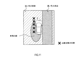
S106の処理の具体的な事例について、図11を参照しながら説明する。この図11の事例では、車両2の位置から左後方に向けて車両2自体の影が路面上に伸びている状況を想定している。さらに、車両2が通行している道路において、車両2の右側の路面だけが、舗装の補修跡のように周囲よりも濃い色を呈している。このような状況下において、車両周囲認識装置1が、各カメラ20a~20dにより撮像された画像間で色調を比較した場合、左カメラ20cにより撮像された画像と右カメラ20dにより撮像された画像との間で色調に差異が観測される。
A specific example of the process of S106 will be described with reference to FIG. In the example of FIG. 11, it is assumed that the shadow of the vehicle 2 itself extends on the road surface from the position of the vehicle 2 toward the left rear. Furthermore, on the road where the vehicle 2 is passing, only the road surface on the right side of the vehicle 2 has a darker color than the surrounding like a pavement repair trace. Under such circumstances, when the vehicle surroundings recognition apparatus 1 compares the color tones of the images captured by the cameras 20a to 20d, the image captured by the left camera 20c and the image captured by the right camera 20d A difference in color tone is observed between
図11の事例のように、左右2つの画像の間で色調が異なる場合、それら2つの画像間で画素の輝度及び青色成分を比較しても、影を的確に判別できない可能性がある。そこで、車両周囲認識装置1は、複数の画像間で色調が異なる場合には、同一の画像内から抽出した比較対象の画素同士で輝度及び青色成分の強度を比較することによって影を検出する。
As in the case of FIG. 11, when the color tone is different between the two left and right images, there is a possibility that the shadow can not be accurately determined even by comparing the luminance and the blue component of the pixel between the two images. Therefore, when the color tone is different between a plurality of images, the vehicle periphery recognition device 1 detects a shadow by comparing the luminance and the intensity of the blue component between pixels to be compared extracted from within the same image.
また、たとえ道路の路面の色調が均一であったとしても、複数のカメラの間でホワイトバランスの設定に差異がある場合、複数の画像の間で色調に差異が観測される。このような場合においても、車両周囲認識装置1は、同一の画像内から抽出した比較対象の画素同士で輝度及び青色成分の強度を比較することによって影を検出する。
Moreover, even if the color tone of the road surface of the road is uniform, if there is a difference in the setting of the white balance among the plurality of cameras, a difference in the color tone is observed among the plurality of images. Even in such a case, the vehicle surrounding recognition device 1 detects a shadow by comparing the luminance and the intensity of the blue component between pixels to be compared extracted from within the same image.
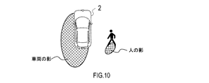
図3のフローチャートの説明に戻る。補足として、S104及びS106では、車両周囲認識装置1は、車両2の近傍の路面において検出された影に該当する画素の輝度及び色を表す画素値を取得する。そして、車両周囲認識装置1は、取得した影の画素値と、画像全体の画素の画素値とを比較して影か否かを判定することにより、画像全体における影領域を検出する。このようにすることで、図10に例示されるように、車両2自体の影だけでなく、車両2の周囲に存在する他の物体の影についても、速やかにかつ的確に検出することができる。
The description will return to the flowchart of FIG. Supplementally, in S104 and S106, the vehicle surrounding recognition device 1 acquires pixel values representing the luminance and color of the pixel corresponding to the shadow detected on the road surface near the vehicle 2. And the vehicle periphery recognition apparatus 1 detects the shadow area | region in the whole image by determining whether it is a shadow by comparing the pixel value of the acquired shadow and the pixel value of the pixel of the whole image. By doing this, as exemplified in FIG. 10, not only the shadow of the vehicle 2 itself but also the shadows of other objects present around the vehicle 2 can be detected promptly and accurately. .
S108では、車両周囲認識装置1は、S104及びS106において各画像から検出された影領域を統合して、車両2の周囲全体における影領域の位置を特定する。S110では、車両周囲認識装置1は、S104及びS106において検出された影の輝度及び青色成分を表す特徴量をメモリに記憶する。S110で記憶された影の特徴量については、次回以降の画像認識処理において、後に撮像された画像内の影を検出する際の基準として利用することで、影の検出を高速化できる。さらに、影が伸びる方向を記憶しておき、次回以降の画像認識処理において比較対象の画素を抽出する位置を決める基準に利用してもよい。なお、S100~S110の処理が、影検出部11の機能が実行する処理に相当する。
In S108, the vehicle periphery recognition apparatus 1 unifies the shadow area detected from each image in S104 and S106, and specifies the position of the shadow area in the whole circumference of the vehicle 2. In S110, the vehicle surrounding recognition device 1 stores, in the memory, feature quantities representing the brightness and the blue component of the shadow detected in S104 and S106. The shadow feature can be detected at high speed by using the feature amount of the shadow stored in S110 as a reference for detecting the shadow in the image captured later in the image recognition process from the next time onward. Furthermore, the direction in which the shadow extends may be stored and used as a reference for determining the position at which the pixel to be compared is extracted in the image recognition processing from the next time onward. The processing of S100 to S110 corresponds to the processing executed by the function of the shadow detection unit 11.
S112では、車両周囲認識装置1は、各カメラ20a~20dにより撮像された画像の中から特徴点を検出する。本実施形態では、例えば、画像内において画素値が不連続に変化している箇所を特徴点として検出する。また、車両周囲認識装置1は、検出された影領域内で特徴点を探索する場合には、特徴点と判定すべき画素値の変化の閾値を、他の領域に適用する閾値から変更するとよい。なお、S112の処理が、特徴点検出部12の機能が実行する処理に相当する。
In S112, the vehicle periphery recognition device 1 detects feature points from the images captured by the cameras 20a to 20d. In the present embodiment, for example, a place where the pixel value changes discontinuously in the image is detected as a feature point. In addition, when searching for a feature point in the detected shadow area, the vehicle periphery recognition apparatus 1 may change the threshold of the change in the pixel value to be determined as the feature point from the threshold applied to other areas. . The process of S112 corresponds to the process performed by the function of the feature point detection unit 12.
S114では、車両周囲認識装置1は、S104又はS106の処理において画像内に存在する影領域が検出されたか否かに応じて、処理を分岐させる。具体的には、画像内に影領域が存在する場合(S114:YES)、車両周囲認識装置1は処理をS116に移す。一方、画像内に影領域が存在しない場合(S114:NO)、車両周囲認識装置1は、S116をスキップしてS118に処理を移す。
In S114, the vehicle periphery recognition device 1 branches the process depending on whether the shadow area present in the image is detected in the process of S104 or S106. Specifically, if there is a shadow area in the image (S114: YES), the vehicle surroundings recognition device 1 shifts the processing to S116. On the other hand, when there is no shadow area in the image (S114: NO), the vehicle surroundings recognition device 1 skips S116 and shifts the processing to S118.
S116では、車両周囲認識装置1は、S112において画像から検出された特徴点群について、S108において特定された影領域と日向との境界である影エッジに該当する特徴点を除去する。具体的には、車両周囲認識装置1は、検出された特徴点の周囲に、記憶されている影の輝度及び青色成分の特徴量と同等の箇所があれば、その特徴点を影エッジに該当する特徴点であると判別し、その判別された特徴点を除去する。
In S116, the vehicle periphery recognition apparatus 1 removes the feature point applicable to the shadow edge which is a boundary of the shadow area | region identified in S108 and the sunday about the feature point group detected from the image in S112. Specifically, if there is a portion equivalent to the stored feature intensity of the shadow and the feature amount of the blue component around the detected feature point, the vehicle periphery recognition device 1 corresponds the feature point to the shadow edge It discriminate | determines that it is a feature point to be, and the determined feature point is removed.
また、図12に例示されるように、車両2の影の中に画像認識の対象物であるレーンマーカーの白線がある状況下において、車両周囲認識装置1は、次のようにして特徴点が影エッジに該当するか否かを判別するとよい。図12は、車両2の影の中に対象物である白線のエッジを形成する特徴点が検出された状況を表している。影の中で白線の特徴点が検出された場合、影の中の路面と影の中と白線との間で画素値のギャップが大きいため、この特徴点を影の中の路面と日向の路面との境界と誤認する可能性がある。
Further, as illustrated in FIG. 12, in the situation where the white line of the lane marker that is the object of image recognition is in the shadow of the vehicle 2, the vehicle periphery recognition device 1 has feature points as follows. It may be determined whether or not it corresponds to a shadow edge. FIG. 12 shows a situation in which a feature point forming an edge of a white line which is an object in a shadow of a vehicle 2 is detected. When a white line feature point is detected in the shadow, the pixel value gap is large between the road surface in the shadow and the white line in the shadow, so the feature point is used as the road surface in the shadow and the road surface in the sun May be mistaken as a border with
そこで、車両周囲認識装置1は、影の中に存在する特徴点について、レーンマーカーの幅に相当する画像上の距離だけ道路の幅方向にオフセットした領域の画素値を確認する。そして、車両周囲認識装置1は、影の中に存在する特徴点と同等の画素値がレーンマーカーの幅で分布しているか否かによって、当該特徴点が影の中のレーンマーカーであるか、影と日向との境界であるかを判別する。
Therefore, the vehicle periphery recognition device 1 confirms the pixel values of the area offset in the width direction of the road by the distance on the image corresponding to the width of the lane marker, for the feature points present in the shadow. Then, the vehicle surrounding recognition device 1 determines whether the feature point is a lane marker in the shadow depending on whether pixel values equivalent to the feature points present in the shadow are distributed in the width of the lane marker, Determine if it is the boundary between the shadow and the sun.
また、図13に例示されるように、車両2の影の側方にタール等の黒い物体が帯状に存在する状況下において、車両周囲認識装置1は、次のようにして検出された特徴点が影エッジに該当するか否かを判別するとよい。図13は、車両2の影と黒い物体との間に、影エッジを形成する特徴点が検出された状況を表している。影と黒い物体との間に特徴点が検出された場合、その特徴点の周囲の明るい路面を、レーンマーカーの白線と誤認識する可能性がある。
In addition, as illustrated in FIG. 13, in a situation where a black object such as tar is present in a band shape on the side of the shadow of the vehicle 2, the vehicle periphery recognition device 1 detects feature points as follows: It may be determined whether or not the image corresponds to a shadow edge. FIG. 13 shows a situation where a feature point forming a shadow edge is detected between the shadow of the vehicle 2 and a black object. When a feature point is detected between a shadow and a black object, the bright road surface around the feature point may be misrecognized as the white line of the lane marker.
そこで、車両周囲認識装置1は、影と黒い物体との間に挟まれた領域の画素値を、予め取得しておいた日向の路面の画素値と照合する。照合の結果、影と黒い物体との間に挟まれた領域の画素値が日向の路面の画素値と同等である場合、車両周囲認識装置1は、その領域を日向の路面と判別する。この場合、車両周囲認識装置1は、影と黒い物体との影との間に存在する特徴点を影エッジとして除去する。
Then, the vehicle periphery recognition device 1 collates the pixel value of the area sandwiched between the shadow and the black object with the pixel value of the road surface of the sun which has been acquired in advance. As a result of the collation, when the pixel value of the area sandwiched between the shadow and the black object is equal to the pixel value of the road surface on the sunny side, the vehicle periphery recognition apparatus 1 determines the area as the road surface on the sunny side. In this case, the vehicle periphery recognition apparatus 1 removes feature points existing between the shadow and the shadow of the black object as a shadow edge.
図3のフローチャートの説明に戻る。S114及びS116の処理が、影エッジ除去部13の機能が実行する処理に相当する。次のS118では、車両周囲認識装置1は、S116までの処理を経て残った画像上の特徴点群について、タール反射除去処理を施す。S118のタール反射除去処理の手順について、図4のフローチャートを参照しながら説明する。このタール反射除去処理は、画像上で検出された特徴点群の中から、道路上に存在するタール等の油状の汚れに反射された光に起因する特徴点を除去する処理である。
The description will return to the flowchart of FIG. The processes of S114 and S116 correspond to the process performed by the function of the shadow edge removing unit 13. In the next S118, the vehicle periphery recognition device 1 performs tar reflection removal processing on the feature points on the image remaining after the processing up to S116. The procedure of the tar reflection removal process of S118 will be described with reference to the flowchart of FIG. The tar reflection removal processing is processing for removing, from the feature point group detected on the image, the feature points caused by the light reflected by the oily stain such as tar existing on the road.
S200では、車両周囲認識装置1は、既に検出された影の伸びる方向に基づいて、太陽の位置を推定する。具体的には、車両周囲認識装置1は、影の伸びる方向の反対側に太陽が存在する位置があると推定する。S202では、車両周囲認識装置1は、S200において推定された太陽の位置に基づいて、画像上においてタール等の反射光が写っている位置を推定する。具体的には、車両周囲認識装置1は、画像上において、太陽の位置と車両2との間の路面に該当する領域で所定の閾値以上の輝度を示す箇所を、タール等の反射光が写っている位置として特定する。
In S200, the vehicle surrounding recognition device 1 estimates the position of the sun based on the direction in which the shadow has already been detected. Specifically, the vehicle periphery recognition device 1 estimates that there is a position where the sun is present on the opposite side of the direction in which the shadow extends. In S202, based on the position of the sun estimated in S200, the vehicle periphery recognition apparatus 1 estimates the position where reflected light, such as tar, is reflected on the image. Specifically, in the image, the vehicle periphery recognition device 1 reflects light such as tar on a portion showing a luminance equal to or greater than a predetermined threshold in a region corresponding to the road surface between the position of the sun and the vehicle 2. As the location where
S204では、車両周囲認識装置1は、画像の中にタール等の反射光が存在するか否かに応じて処理を分岐させる。画像の中にタール等の反射光が存在する(S204:YES)、車両周囲認識装置1は処理をS206に移す。S206では、車両周囲認識装置1は、画像から検出された特徴点群について、S202で推定されたタール等の反射光に該当する特徴点を除去する。一方、画像の中にタール等の反射光が存在しない場合(S204:NO)、車両周囲認識装置1は、S206をスキップしてタール反射除去処理を終了する。
In S204, the vehicle periphery recognition device 1 branches the process depending on whether or not the reflected light such as tar is present in the image. The reflected light such as tar is present in the image (S204: YES), the vehicle surroundings recognition apparatus 1 shifts the process to S206. In S206, the vehicle periphery recognition apparatus 1 removes the feature point applicable to reflected light, such as tar estimated in S202, about the feature point group detected from the image. On the other hand, when there is no reflected light such as tar in the image (S204: NO), the vehicle surroundings recognition device 1 skips S206 and ends the tar reflection removal process.
図3のフローチャートの説明に戻る。次のS120では、車両周囲認識装置1は、S118までの処理を経て残った画像上の特徴点群に基づいて、特定の対象物に該当する物体を検出する物体認識処理を実行する。具体的には、車両周囲認識装置1は、画像の特徴点を用いる周知の画像認識アルゴリズムを用いて、レーンマーカー等の対象物を検出する。また、車両周囲認識装置1は、対象物として、レーンマーカーに限らず、車両や人物等の交通移動体や、道路標示等の物体も検出するように構成されていてもよい。なお、S120の処理が、認識部14の機能として実行する処理に相当する。以上で車両周囲認識装置1は、画像認識処理を終了する。
The description will return to the flowchart of FIG. In the next S120, the vehicle periphery recognition apparatus 1 executes an object recognition process of detecting an object corresponding to a specific object based on the feature point group on the image remaining after the process up to S118. Specifically, the vehicle periphery recognition apparatus 1 detects an object such as a lane marker using a known image recognition algorithm using feature points of an image. Further, the vehicle periphery recognition apparatus 1 may be configured to detect not only a lane marker but also a traffic moving object such as a vehicle or a person or an object such as a road marking as an object. The process of S120 corresponds to the process executed as the function of the recognition unit 14. Above, the vehicle surrounding recognition apparatus 1 complete | finishes an image recognition process.
[効果]
実施形態の車両周囲認識装置1によれば、以下の効果を奏する。
車両周囲認識装置1は、画像の輝度だけでなく、画像が示す色に含まれる青色成分の度合に基づいて影領域を判定する。このようにすることで、画像の明暗の変化に対するロバスト性を向上させ、影領域を精度よく検出することができる。そして、車両周囲認識装置1は、画像内から検出された特徴点群から影領域のエッジに該当する特徴点を除去することで、目的とする対象物を的確に検出できる。 [effect]
According to the vehiclesurroundings recognition device 1 of the embodiment, the following effects can be obtained.
The vehicle surroundingrecognition device 1 determines the shadow area based not only on the luminance of the image but also on the degree of the blue component contained in the color indicated by the image. By doing this, it is possible to improve the robustness to changes in light and dark of an image and to detect a shadow area with high accuracy. Then, the vehicle periphery recognition device 1 can accurately detect the target object by removing the feature points corresponding to the edge of the shadow area from the feature point group detected from within the image.
実施形態の車両周囲認識装置1によれば、以下の効果を奏する。
車両周囲認識装置1は、画像の輝度だけでなく、画像が示す色に含まれる青色成分の度合に基づいて影領域を判定する。このようにすることで、画像の明暗の変化に対するロバスト性を向上させ、影領域を精度よく検出することができる。そして、車両周囲認識装置1は、画像内から検出された特徴点群から影領域のエッジに該当する特徴点を除去することで、目的とする対象物を的確に検出できる。 [effect]
According to the vehicle
The vehicle surrounding
また、車両周囲認識装置1は、複数のカメラ20a~20dにより撮像された異なる画像の間で画素を比較して影の検出を行うことができる。このようにすることで、影が伸びる方向に応じて車両2の周囲における様々な方向から的確に影を検出できる。
In addition, the vehicle periphery recognition device 1 can detect a shadow by comparing pixels between different images captured by the plurality of cameras 20a to 20d. By doing this, the shadow can be detected accurately from various directions around the vehicle 2 according to the direction in which the shadow extends.
また、車両周囲認識装置1は、複数の画像の間で色調が同等である場合、異なる画像の間で画素を比較して影の検出を行う。一方、複数の画像の間で色調が異なる場合、車両周囲認識装置1は、同一の画像の中の画素同士を比較して影の検出を行う。このようにすることで、色調が異なる画像の間で画素を比較することを避けて、画像の輝度及び色に基づく影の検出を精度よく行うことができる。
In addition, when the color tone is the same among a plurality of images, the vehicle periphery recognition device 1 detects pixels by comparing pixels among different images. On the other hand, when the color tone is different among a plurality of images, the vehicle surrounding recognition device 1 detects pixels by comparing pixels in the same image. By doing this, it is possible to accurately detect the shadow based on the brightness and the color of the image while avoiding the comparison of the pixels between the images having different color tones.
[変形例]
(a)上述の実施形態では、撮像部として4台のカメラ20a~20dを用いる事例について説明した。これに限らず、車両2は、少なくとも1台のカメラを備えていればよい。車両2が1台のカメラを備える場合、車両周囲認識装置1は、1台のカメラにより撮像された画像を鳥瞰画像に変換したり、その画像の中から検出された影領域のエッジを除去した上で、対象物の検出を行う。また、上記実施形態では、YUVカラーモデルで表現されるデジタルカラー画像を用いて影領域を特定する事例について説明した。これに限らず、例えば、RGBカラーモデルで表現されるデジタルカラー画像を用いて影領域を特定する構成であってもよい。 [Modification]
(A) In the above-described embodiment, the case where fourcameras 20a to 20d are used as the imaging unit has been described. Not limited to this, the vehicle 2 may have at least one camera. When the vehicle 2 includes one camera, the vehicle periphery recognition apparatus 1 converts the image captured by the one camera into a bird's-eye view image, or removes the edge of the shadow area detected from the image. Above, detect the object. Further, in the above embodiment, the case of specifying the shadow area using the digital color image represented by the YUV color model has been described. For example, the configuration may be such that a shadow area is specified using a digital color image represented by an RGB color model.
(a)上述の実施形態では、撮像部として4台のカメラ20a~20dを用いる事例について説明した。これに限らず、車両2は、少なくとも1台のカメラを備えていればよい。車両2が1台のカメラを備える場合、車両周囲認識装置1は、1台のカメラにより撮像された画像を鳥瞰画像に変換したり、その画像の中から検出された影領域のエッジを除去した上で、対象物の検出を行う。また、上記実施形態では、YUVカラーモデルで表現されるデジタルカラー画像を用いて影領域を特定する事例について説明した。これに限らず、例えば、RGBカラーモデルで表現されるデジタルカラー画像を用いて影領域を特定する構成であってもよい。 [Modification]
(A) In the above-described embodiment, the case where four
(b)夜間や太陽光の届かないトンネル内等では、レイリー散光の影響が顕著に表われないため、影の画像の青色成分は強くならない。したがって、車両周囲認識装置1は、夜間やトンネル内において影を検出する場合、画像の青色成分に関する判定を行わず、輝度だけを判定するように構成されていてもよい。また、光源としてナトリウムランプが用いられている環境下では、影の画像について黄色成分が強く現れる傾向がある。そこで、車両周囲認識装置1は、光源としてナトリウムランプが用いられている環境下において影を検出する場合、画像の黄色成分の度合について判定を行うように構成されていてもよい。
(B) At night or in a tunnel where sunlight does not reach, the blue component of the image of the shadow does not become strong because the influence of Rayleigh light scattering is not apparent. Therefore, when detecting a shadow at night or in a tunnel, the vehicle surrounding recognition device 1 may be configured to determine only the luminance without performing the determination regarding the blue component of the image. Also, in an environment where a sodium lamp is used as a light source, the yellow component tends to appear strongly in the shadow image. Therefore, when detecting a shadow in an environment where a sodium lamp is used as a light source, the vehicle surrounding recognition device 1 may be configured to make a determination on the degree of the yellow component of the image.
(c)車両周囲認識装置1は、検出した影の方向と日時に基づいて方位を推定するように構成されていてもよい。推定した方位から、路面上に存在するタール等が光を反射して強く光る可能性の高い領域を推定することができる。
(C) The vehicle surrounding recognition device 1 may be configured to estimate the heading based on the detected shadow direction and date and time. From the estimated direction, it is possible to estimate an area where tar or the like present on the road surface has a high possibility of reflecting light and strongly emitting light.
(d)上記各実施形態における1つの構成要素が有する機能を複数の構成要素に分担させたり、複数の構成要素が有する機能を1つの構成要素に発揮させたりしてもよい。また、上記各実施形態の構成の一部を省略してもよい。また、上記各実施形態の構成の少なくとも一部を、他の上記実施形態の構成に対して付加、置換等してもよい。なお、特許請求の範囲に記載の文言から特定される技術思想に含まれるあらゆる態様が、本開示の実施形態である。
(D) The function possessed by one component in each of the above embodiments may be shared by a plurality of components, or the function possessed by a plurality of components may be exhibited by one component. In addition, part of the configuration of each of the above embodiments may be omitted. In addition, at least a part of the configuration of each of the above-described embodiments may be added to or replaced with the configuration of the other above-described embodiments. In addition, all the aspects contained in the technical thought specified from the wording described in a claim are embodiments of this indication.
(e)上述した車両周囲認識装置1を構成要件とするシステム、車両周囲認識装置1としてコンピュータを機能させるためのプログラム、このプログラムを記録した半導体メモリ等の実体的な記録媒体、物体認識方法等の種々の形態で本開示を実現できる。
(E) A system having the above-described vehicle surrounding recognition apparatus 1 as a component, a program for causing a computer to function as the vehicle surrounding recognition apparatus 1, a substantial recording medium such as a semiconductor memory storing this program, an object recognition method, etc. The present disclosure can be implemented in various forms.
Claims (6)
- 車両(2)の周囲の道路を含む範囲を撮像するように当該車両に搭載された撮像部(20)によって撮像された画像を取得し、その取得された画像から前記車両の周囲に存在する特定の対象物を認識する車両周囲認識装置(1)であって、
前記画像を構成する複数の要素の間で、各要素が表す色に含まれる特定の色成分の度合、及び輝度をそれぞれ比較した差分に基づいて、前記画像において道路の路面上に影がかかっている領域である影領域を検出するように構成された影検出部(11)と、
前記画像の中から特徴点を検出するように構成された特徴点検出部(12)と、
前記影検出部により検出された影領域と前記特徴点検出部により検出された特徴点群とに基づいて、前記対象物を認識するように構成された認識部(14)と、
を備える車両周囲認識装置。 An image captured by the imaging unit (20) mounted on the vehicle is acquired so as to image a range including the road around the vehicle (2), and the image existing from the acquired image is identified in the periphery of the vehicle A vehicle surrounding recognition device (1) for recognizing an object of
A shadow is cast on the road surface of the road in the image, based on the difference between the degree of a specific color component included in the color represented by each element and the luminance among the elements constituting the image. A shadow detection unit (11) configured to detect a shadow area that is
A feature point detection unit (12) configured to detect feature points from the image;
A recognition unit (14) configured to recognize the object based on the shadow area detected by the shadow detection unit and the feature point group detected by the feature point detection unit;
Vehicle surroundings recognition device provided with - 前記撮像部は、前記車両の周囲の異なる範囲を撮像するように構成された複数のカメラ(20a,20b,20c,20d)を有し、
前記影検出部は、前記複数のカメラにより撮像された異なる画像の間で、各画像内の要素における特定の色成分の度合及び輝度をそれぞれ比較することによって前記影領域を検出するように構成されている、
請求項1に記載の車両周囲認識装置。 The imaging unit comprises a plurality of cameras (20a, 20b, 20c, 20d) configured to image different areas around the vehicle,
The shadow detection unit is configured to detect the shadow area by comparing the degree and luminance of a specific color component in an element in each image among different images captured by the plurality of cameras. ing,
The vehicle surroundings recognition device according to claim 1. - 前記影検出部は、前記複数のカメラにより撮像された複数の画像の間で色調を比較し、色調が同じと判定された複数の画像の間で、各画像内の要素における特定の色成分の度合及び輝度をそれぞれ比較することによって前記影領域を検出するように構成されている、
請求項2に記載の車両周囲認識装置。 The shadow detection unit compares color tones among a plurality of images captured by the plurality of cameras, and among a plurality of images determined to have the same color tone, a specific color component of an element in each image Configured to detect the shadow area by comparing the degree and the brightness respectively;
The vehicle surroundings recognition device according to claim 2. - 前記影検出部は、前記画像における特定の領域内に含まれる複数の要素における特定の色成分の度合及び輝度をそれぞれ比較することによって前記影領域を検出するように構成されている、
請求項1ないし請求項3の何れか1項に記載の車両周囲認識装置。 The shadow detection unit is configured to detect the shadow area by comparing the degree and luminance of specific color components of a plurality of elements included in a specific area of the image.
The vehicle surroundings recognition device according to any one of claims 1 to 3. - 前記影検出部は、検出された影領域に該当する部位の色及び輝度を表す画像情報を記憶し、その記憶された画像情報を用いて、後に撮像された画像に含まれる影領域を検出するように構成されている、
請求項1ないし請求項3の何れか1項に記載の車両周囲認識装置。 The shadow detection unit stores image information representing the color and luminance of a portion corresponding to the detected shadow region, and detects the shadow region included in the image captured later using the stored image information. Is configured as
The vehicle surroundings recognition device according to any one of claims 1 to 3. - 前記特徴点検出部により検出された特徴点群から、前記影検出部により検出された影領域のエッジに該当する特徴点を除去するように構成された影エッジ除去部(13)を更に備え、
前記認識部は、前記影エッジ除去部により影領域のエッジが除去された後の特徴点群から、前記対象物を認識するように構成されている、
請求項1ないし請求項5の何れか1項に記載の車両周囲認識装置。 It further comprises a shadow edge removal unit (13) configured to remove feature points corresponding to the edge of the shadow area detected by the shadow detection unit from the feature point group detected by the feature point detection unit;
The recognition unit is configured to recognize the object from a group of feature points after the shadow edge removing unit has removed the edge of the shadow region.
A vehicle surrounding recognition device according to any one of claims 1 to 5.
Priority Applications (1)
| Application Number | Priority Date | Filing Date | Title |
|---|---|---|---|
| US16/739,472 US11282235B2 (en) | 2017-07-14 | 2020-01-10 | Vehicle surroundings recognition apparatus |
Applications Claiming Priority (2)
| Application Number | Priority Date | Filing Date | Title |
|---|---|---|---|
| JP2017-137853 | 2017-07-14 | ||
| JP2017137853A JP6720931B2 (en) | 2017-07-14 | 2017-07-14 | Vehicle surrounding recognition device |
Related Child Applications (1)
| Application Number | Title | Priority Date | Filing Date |
|---|---|---|---|
| US16/739,472 Continuation US11282235B2 (en) | 2017-07-14 | 2020-01-10 | Vehicle surroundings recognition apparatus |
Publications (1)
| Publication Number | Publication Date |
|---|---|
| WO2019013252A1 true WO2019013252A1 (en) | 2019-01-17 |
Family
ID=65002005
Family Applications (1)
| Application Number | Title | Priority Date | Filing Date |
|---|---|---|---|
| PCT/JP2018/026190 WO2019013252A1 (en) | 2017-07-14 | 2018-07-11 | Vehicle surroundings recognition device |
Country Status (3)
| Country | Link |
|---|---|
| US (1) | US11282235B2 (en) |
| JP (1) | JP6720931B2 (en) |
| WO (1) | WO2019013252A1 (en) |
Families Citing this family (5)
| Publication number | Priority date | Publication date | Assignee | Title |
|---|---|---|---|---|
| CN112020688A (en) * | 2018-03-26 | 2020-12-01 | 捷普有限公司 | Apparatus, system, and method for autonomous robotic navigation using depth assessment |
| US11164031B2 (en) * | 2018-06-26 | 2021-11-02 | Here Global B.V. | System and method for analyzing an image of a vehicle |
| US10762681B2 (en) | 2018-06-26 | 2020-09-01 | Here Global B.V. | Map generation system and method for generating an accurate building shadow |
| JP7310527B2 (en) * | 2019-10-14 | 2023-07-19 | 株式会社デンソー | Obstacle identification device and obstacle identification program |
| US11328607B2 (en) * | 2020-03-20 | 2022-05-10 | Aptiv Technologies Limited | System and method of detecting vacant parking spots |
Citations (4)
| Publication number | Priority date | Publication date | Assignee | Title |
|---|---|---|---|---|
| JP2009031939A (en) * | 2007-07-25 | 2009-02-12 | Advanced Telecommunication Research Institute International | Image processing apparatus, method and program |
| JP4270183B2 (en) * | 2005-08-22 | 2009-05-27 | トヨタ自動車株式会社 | White line detector |
| JP2010237976A (en) * | 2009-03-31 | 2010-10-21 | Kyushu Institute Of Technology | Light source information obtaining device, shading detection device, shading removal device, and those methods and programs |
| JP2014035561A (en) * | 2012-08-07 | 2014-02-24 | Nissan Motor Co Ltd | Vehicle travel support device and vehicle travel support method |
Family Cites Families (8)
| Publication number | Priority date | Publication date | Assignee | Title |
|---|---|---|---|---|
| JP3083918B2 (en) * | 1992-06-26 | 2000-09-04 | 本田技研工業株式会社 | Image processing device |
| JP3463858B2 (en) * | 1998-08-27 | 2003-11-05 | 矢崎総業株式会社 | Perimeter monitoring device and method |
| US7184890B2 (en) * | 2003-11-24 | 2007-02-27 | The Boeing Company | Cloud shadow detection: VNIR-SWIR |
| CN101833749B (en) * | 2009-03-12 | 2012-03-28 | 株式会社理光 | Device and method for detecting shadow in image |
| EP2287807A1 (en) * | 2009-07-21 | 2011-02-23 | Nikon Corporation | Image processing device, image processing program, and imaging device |
| JP5066558B2 (en) | 2009-09-17 | 2012-11-07 | 日立オートモティブシステムズ株式会社 | Vehicle shadow recognition device |
| JP6003226B2 (en) * | 2012-05-23 | 2016-10-05 | 株式会社デンソー | Vehicle surrounding image display control apparatus and vehicle surrounding image display control program |
| US9430715B1 (en) * | 2015-05-01 | 2016-08-30 | Adobe Systems Incorporated | Identifying and modifying cast shadows in an image |
-
2017
- 2017-07-14 JP JP2017137853A patent/JP6720931B2/en active Active
-
2018
- 2018-07-11 WO PCT/JP2018/026190 patent/WO2019013252A1/en active Application Filing
-
2020
- 2020-01-10 US US16/739,472 patent/US11282235B2/en active Active
Patent Citations (4)
| Publication number | Priority date | Publication date | Assignee | Title |
|---|---|---|---|---|
| JP4270183B2 (en) * | 2005-08-22 | 2009-05-27 | トヨタ自動車株式会社 | White line detector |
| JP2009031939A (en) * | 2007-07-25 | 2009-02-12 | Advanced Telecommunication Research Institute International | Image processing apparatus, method and program |
| JP2010237976A (en) * | 2009-03-31 | 2010-10-21 | Kyushu Institute Of Technology | Light source information obtaining device, shading detection device, shading removal device, and those methods and programs |
| JP2014035561A (en) * | 2012-08-07 | 2014-02-24 | Nissan Motor Co Ltd | Vehicle travel support device and vehicle travel support method |
Also Published As
| Publication number | Publication date |
|---|---|
| JP6720931B2 (en) | 2020-07-08 |
| US11282235B2 (en) | 2022-03-22 |
| JP2019020956A (en) | 2019-02-07 |
| US20200151912A1 (en) | 2020-05-14 |
Similar Documents
| Publication | Publication Date | Title |
|---|---|---|
| WO2019013252A1 (en) | Vehicle surroundings recognition device | |
| US8036427B2 (en) | Vehicle and road sign recognition device | |
| US8319854B2 (en) | Shadow removal in an image captured by a vehicle based camera using a non-linear illumination-invariant kernel | |
| US8294794B2 (en) | Shadow removal in an image captured by a vehicle-based camera for clear path detection | |
| EP1887522B1 (en) | Vehicle and road sign recognition device | |
| EP3098753A1 (en) | Lane detection | |
| US8345100B2 (en) | Shadow removal in an image captured by a vehicle-based camera using an optimized oriented linear axis | |
| WO2018008461A1 (en) | Image processing device | |
| JP7230507B2 (en) | Deposit detection device | |
| KR101026778B1 (en) | Vehicle image detection apparatus | |
| JP6413318B2 (en) | Vehicle detection device, system, and program | |
| JP5338762B2 (en) | White balance coefficient calculation device and program | |
| JP6375911B2 (en) | Curve mirror detector | |
| KR101402089B1 (en) | Apparatus and Method for Obstacle Detection | |
| JP2015061163A (en) | Shielding detector | |
| US10997743B2 (en) | Attachable matter detection apparatus | |
| JP7200893B2 (en) | Attached matter detection device and attached matter detection method | |
| JP5862217B2 (en) | Marker detection and tracking device | |
| JP2010286995A (en) | Image processing system for vehicle | |
| JP4941843B2 (en) | Road marking image processing apparatus, road marking image processing method, and road marking image processing program | |
| KR101875786B1 (en) | Method for identifying vehicle using back light region in road image | |
| WO2020196536A1 (en) | Photographing system and image processing device | |
| JPH1166490A (en) | Vehicle detecting method | |
| JP2007257242A (en) | White line recognition device | |
| JP2021052233A (en) | Deposit detection device and deposit detection method |
Legal Events
| Date | Code | Title | Description |
|---|---|---|---|
| 121 | Ep: the epo has been informed by wipo that ep was designated in this application |
Ref document number: 18832050 Country of ref document: EP Kind code of ref document: A1 |
|
| NENP | Non-entry into the national phase |
Ref country code: DE |
|
| 122 | Ep: pct application non-entry in european phase |
Ref document number: 18832050 Country of ref document: EP Kind code of ref document: A1 |