WO2019013192A1 - Lid device for vehicle - Google Patents
Lid device for vehicle Download PDFInfo
- Publication number
- WO2019013192A1 WO2019013192A1 PCT/JP2018/025997 JP2018025997W WO2019013192A1 WO 2019013192 A1 WO2019013192 A1 WO 2019013192A1 JP 2018025997 W JP2018025997 W JP 2018025997W WO 2019013192 A1 WO2019013192 A1 WO 2019013192A1
- Authority
- WO
- WIPO (PCT)
- Prior art keywords
- lid
- link member
- biasing
- contact portion
- reference position
- Prior art date
Links
Images


Classifications
-
- B—PERFORMING OPERATIONS; TRANSPORTING
- B60—VEHICLES IN GENERAL
- B60K—ARRANGEMENT OR MOUNTING OF PROPULSION UNITS OR OF TRANSMISSIONS IN VEHICLES; ARRANGEMENT OR MOUNTING OF PLURAL DIVERSE PRIME-MOVERS IN VEHICLES; AUXILIARY DRIVES FOR VEHICLES; INSTRUMENTATION OR DASHBOARDS FOR VEHICLES; ARRANGEMENTS IN CONNECTION WITH COOLING, AIR INTAKE, GAS EXHAUST OR FUEL SUPPLY OF PROPULSION UNITS IN VEHICLES
- B60K15/00—Arrangement in connection with fuel supply of combustion engines or other fuel consuming energy converters, e.g. fuel cells; Mounting or construction of fuel tanks
- B60K15/03—Fuel tanks
- B60K15/04—Tank inlets
- B60K15/05—Inlet covers
-
- B—PERFORMING OPERATIONS; TRANSPORTING
- B60—VEHICLES IN GENERAL
- B60K—ARRANGEMENT OR MOUNTING OF PROPULSION UNITS OR OF TRANSMISSIONS IN VEHICLES; ARRANGEMENT OR MOUNTING OF PLURAL DIVERSE PRIME-MOVERS IN VEHICLES; AUXILIARY DRIVES FOR VEHICLES; INSTRUMENTATION OR DASHBOARDS FOR VEHICLES; ARRANGEMENTS IN CONNECTION WITH COOLING, AIR INTAKE, GAS EXHAUST OR FUEL SUPPLY OF PROPULSION UNITS IN VEHICLES
- B60K15/00—Arrangement in connection with fuel supply of combustion engines or other fuel consuming energy converters, e.g. fuel cells; Mounting or construction of fuel tanks
- B60K15/03—Fuel tanks
- B60K15/04—Tank inlets
- B60K15/0406—Filler caps for fuel tanks
- B60K15/0409—Provided with a lock
-
- E—FIXED CONSTRUCTIONS
- E05—LOCKS; KEYS; WINDOW OR DOOR FITTINGS; SAFES
- E05F—DEVICES FOR MOVING WINGS INTO OPEN OR CLOSED POSITION; CHECKS FOR WINGS; WING FITTINGS NOT OTHERWISE PROVIDED FOR, CONCERNED WITH THE FUNCTIONING OF THE WING
- E05F1/00—Closers or openers for wings, not otherwise provided for in this subclass
- E05F1/08—Closers or openers for wings, not otherwise provided for in this subclass spring-actuated, e.g. for horizontally sliding wings
- E05F1/10—Closers or openers for wings, not otherwise provided for in this subclass spring-actuated, e.g. for horizontally sliding wings for swinging wings, e.g. counterbalance
- E05F1/1008—Closers or openers for wings, not otherwise provided for in this subclass spring-actuated, e.g. for horizontally sliding wings for swinging wings, e.g. counterbalance with a coil spring parallel with the pivot axis
-
- B—PERFORMING OPERATIONS; TRANSPORTING
- B60—VEHICLES IN GENERAL
- B60K—ARRANGEMENT OR MOUNTING OF PROPULSION UNITS OR OF TRANSMISSIONS IN VEHICLES; ARRANGEMENT OR MOUNTING OF PLURAL DIVERSE PRIME-MOVERS IN VEHICLES; AUXILIARY DRIVES FOR VEHICLES; INSTRUMENTATION OR DASHBOARDS FOR VEHICLES; ARRANGEMENTS IN CONNECTION WITH COOLING, AIR INTAKE, GAS EXHAUST OR FUEL SUPPLY OF PROPULSION UNITS IN VEHICLES
- B60K15/00—Arrangement in connection with fuel supply of combustion engines or other fuel consuming energy converters, e.g. fuel cells; Mounting or construction of fuel tanks
- B60K15/03—Fuel tanks
- B60K15/04—Tank inlets
- B60K2015/0458—Details of the tank inlet
- B60K2015/0461—Details of the tank inlet comprising a filler pipe shutter, e.g. trap, door or flap for fuel inlet
-
- B—PERFORMING OPERATIONS; TRANSPORTING
- B60—VEHICLES IN GENERAL
- B60K—ARRANGEMENT OR MOUNTING OF PROPULSION UNITS OR OF TRANSMISSIONS IN VEHICLES; ARRANGEMENT OR MOUNTING OF PLURAL DIVERSE PRIME-MOVERS IN VEHICLES; AUXILIARY DRIVES FOR VEHICLES; INSTRUMENTATION OR DASHBOARDS FOR VEHICLES; ARRANGEMENTS IN CONNECTION WITH COOLING, AIR INTAKE, GAS EXHAUST OR FUEL SUPPLY OF PROPULSION UNITS IN VEHICLES
- B60K15/00—Arrangement in connection with fuel supply of combustion engines or other fuel consuming energy converters, e.g. fuel cells; Mounting or construction of fuel tanks
- B60K15/03—Fuel tanks
- B60K15/04—Tank inlets
- B60K15/05—Inlet covers
- B60K2015/0515—Arrangements for closing or opening of inlet cover
- B60K2015/053—Arrangements for closing or opening of inlet cover with hinged connection to the vehicle body
-
- Y—GENERAL TAGGING OF NEW TECHNOLOGICAL DEVELOPMENTS; GENERAL TAGGING OF CROSS-SECTIONAL TECHNOLOGIES SPANNING OVER SEVERAL SECTIONS OF THE IPC; TECHNICAL SUBJECTS COVERED BY FORMER USPC CROSS-REFERENCE ART COLLECTIONS [XRACs] AND DIGESTS
- Y02—TECHNOLOGIES OR APPLICATIONS FOR MITIGATION OR ADAPTATION AGAINST CLIMATE CHANGE
- Y02T—CLIMATE CHANGE MITIGATION TECHNOLOGIES RELATED TO TRANSPORTATION
- Y02T10/00—Road transport of goods or passengers
- Y02T10/60—Other road transportation technologies with climate change mitigation effect
- Y02T10/70—Energy storage systems for electromobility, e.g. batteries
-
- Y—GENERAL TAGGING OF NEW TECHNOLOGICAL DEVELOPMENTS; GENERAL TAGGING OF CROSS-SECTIONAL TECHNOLOGIES SPANNING OVER SEVERAL SECTIONS OF THE IPC; TECHNICAL SUBJECTS COVERED BY FORMER USPC CROSS-REFERENCE ART COLLECTIONS [XRACs] AND DIGESTS
- Y02—TECHNOLOGIES OR APPLICATIONS FOR MITIGATION OR ADAPTATION AGAINST CLIMATE CHANGE
- Y02T—CLIMATE CHANGE MITIGATION TECHNOLOGIES RELATED TO TRANSPORTATION
- Y02T10/00—Road transport of goods or passengers
- Y02T10/60—Other road transportation technologies with climate change mitigation effect
- Y02T10/7072—Electromobility specific charging systems or methods for batteries, ultracapacitors, supercapacitors or double-layer capacitors
-
- Y—GENERAL TAGGING OF NEW TECHNOLOGICAL DEVELOPMENTS; GENERAL TAGGING OF CROSS-SECTIONAL TECHNOLOGIES SPANNING OVER SEVERAL SECTIONS OF THE IPC; TECHNICAL SUBJECTS COVERED BY FORMER USPC CROSS-REFERENCE ART COLLECTIONS [XRACs] AND DIGESTS
- Y02—TECHNOLOGIES OR APPLICATIONS FOR MITIGATION OR ADAPTATION AGAINST CLIMATE CHANGE
- Y02T—CLIMATE CHANGE MITIGATION TECHNOLOGIES RELATED TO TRANSPORTATION
- Y02T90/00—Enabling technologies or technologies with a potential or indirect contribution to GHG emissions mitigation
- Y02T90/10—Technologies relating to charging of electric vehicles
- Y02T90/14—Plug-in electric vehicles
Definitions
- the present invention relates to a lid device of a vehicle.
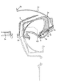
- the lid device 1 includes a housing (sorter) 2 for disposing a filler port and the like, a lid (lid member) 3 for opening and closing the opening 2 a, and an arm extended to the lid 3 and connecting and supporting the lid 3 to the housing 2 3b, the lid 3 pops up from the closed position to the first reference position which is in the process of opening, or is attached to the first reference position which is the closing direction across the second reference position which is further in the opening direction. It has a spring 5 which is biasing means for switching between biasing and biasing to the fully open position (hereinafter referred to as a deadlock).
- a deadlock biasing means for switching between biasing and biasing to the fully open position
- the housing 2 is provided with a cylindrical portion 2 b and a horizontal extension portion 2 c connected to the cylindrical portion.
- the lid 3 comprises a lid body 3a for opening and closing the opening 2a and an arm 3b of gooseneck type.
- the arm 3 b is disposed in the horizontal extension 2 c and pivotally supported by the pin 4.
- symbol 3c is a contact part which the spring 5 (elastic deformation part 5c mentioned later) contact
- the spring 5 extends in the vertical direction as shown in FIG.
- the elastically deformable portion 5c includes an obliquely extending portion 5c1 which extends obliquely upward from the end of the horizontal portion 5b, and a vertically extending portion 5c2 which extends downward from the end of the lid-side horizontal portion 5d.
- symbol 5f is a folding
- the spring 5 described above is incorporated in a state in which the body side fixing portion 5a is fixed to the horizontal extension portion 2c and the lid side fixing portion 5e is fixed to the arm portion 3b, and an urging force in the expansion and contraction direction is applied to the lid 3 It will be Further, depending on the rotational position of the lid 3, the spring 5 has an urging force in the expansion / contraction direction (this urging force is referred to as a “second urging force”) and an urging force in a direction substantially perpendicular to the expansion / contraction direction (this urging force There is a case in which “the first biasing force” is added to the lid 3.
- the elastically deforming portion 5c is elastically deformed by pushing the lid 3 in the closing direction, and the pop-up first biasing force acts to bias the lid 3 from the spring 5 in the opening direction (first biasing Department).
- the second biasing force acts in the direction of closing the lid 3 if the lid fixing portion 5e is at the closing side than the imaginary line 100 connecting the rotation center (pin 4) of the lid 3 and the main body side fixing portion 5a.
- the second biasing force acts in the direction of opening the lid 3. That is, the spring 5 acts as a deadlock for urging the lid 3 in the closing direction to the second reference position beyond the first reference position and urging the lid 3 in the opening direction from the second reference position to the fully open position.
- the lid device As the lid device, the lid is locked by the lock mechanism (not shown) in the closed position, and is rotated to the first reference position by the first biasing force of the spring when the lock mechanism is unlocked. Thereafter, when the lid is turned to the second reference position, the lid is turned from the second reference position to the fully open position by the second biasing force of the spring.
- the second biasing force is applied by the elastic force in the expansion and contraction direction of the spring
- the first biasing force is applied by the elastic force in the direction substantially perpendicular to the expansion and contraction direction. It is possible to generate biasing forces in two different directions independently, thereby improving space efficiency and improving the freedom of layout of each part.
- the lid is separated from the housing at the fully open position to impair the design, and the housing is difficult to be compact due to the presence of the horizontally extending portion.
- the arm is pivotally supported by a pin or the like in a state inserted into the inner back side of the horizontal extension, or a spring engages the main body side fixing portion at a predetermined position in the horizontal extension. It must be stopped and the workability is bad.
- the object of the present invention is to solve the above problems and provide a lid device of a vehicle which enables a compact housing and is excellent in design in a structure in which a lid is moved by a biasing force for pop-up and deadlock. Do. In addition, the lid assembly operability can be favorably performed. Other objectives will be clarified in the following content description.
- a housing in which an oil filler or electric charging port is disposed inside an opening, a lid for opening and closing the opening of the housing, and a connection support for opening and closing the lid
- Link member and the lid can be moved from the closed position to the first reference position which is in the process of opening by the biasing force, and can be moved by the biasing force from the second reference position which is further in the opening direction than the first reference position
- the link member is pivotally supported at one end thereof on the back side of the lid and at the other end thereof on a base member provided in the housing.
- a second link member wherein the biasing member causes the lid to switch from the closed position to the first reference position.
- the biasing member contacts as a point of force in the case of popping up or popping up, for example, in the first embodiment of the invention one leg of the first link member, second embodiment In the embodiment, the first link member 7), and the abutment portion for deadlock for switching the biasing to the first reference position and the biasing to the fully open position across the second reference position (switching of the biasing direction
- the second embodiment of the present invention is characterized in that the step portion 72a) of the first link member 7 is provided.
- a biasing force for pop-up that lifts the lid from the closed position to the first reference position and a bias for switching the biasing from the second reference position to the fully open position and the bias to the first reference position
- the movement of the lid is controlled by two link members as is apparent from each embodiment to achieve compactness or to be installed in the housing. Can simplify the assembly of the biasing member and the assembly to the housing.
- the present invention as described above may be embodied as specified in the following second to fifth embodiments.
- the biasing member is disposed between the first link member and the base member, and the pop-up contact portion is disposed at the lid side of the first link member.
- one leg outer surface 41a described later, and the deadlock abutment portion is disposed on the base member side of the first link member (for example, the other leg described later) It is an inner surface 41b).
- the biasing member is disposed between the first link member and the base member, and the first link member is opposite to the contact portion for pop-up and the contact portion for deadlock.
- the biasing member is disposed between the first link member and the second link member, and the pop-up contact portion is a predetermined portion (for example, the first link member).
- the deadlock contact portion is a predetermined portion of the first link member (for example, a step portion 72a described later). This is a specification based on the second embodiment of the present invention.
- the second link member can also be supported constantly without rattle, and additionally, the pop-up Since the contact portion is a predetermined portion of the first link member and the deadlock contact portion is a predetermined portion of the first link member, the degree of freedom in design can be expanded.
- the base member is a biasing member first contact portion (for example, a window 35a described later) corresponding to the pop-up contact portion, and a biasing member corresponding to the deadlock contact portion It is the structure which has the 2nd contact part for members (for example, the connection part 33b mentioned later). This is a specification based on the first embodiment of the present invention.
- the base member is a first contact portion for the biasing member corresponding to the contact portion for pop-up, and a second for the biasing member corresponding to the contact portion for deadlock. Due to the presence of the contact portion, for example, from the assembled state of the base member, the two link members, and the biasing member, it can be connected to the lid and finally be incorporated into the housing.
- the first contact portion for biasing member is a surface (for example, a lower back surface of a window 35a described later) disposed on the side of the second link member of the base member, and
- the second contact portion for a biasing member is a surface (for example, the front side of a connecting portion 33b described later) disposed on the first ring member side of the base member.
- the biasing member first contact portion is disposed on the second link member side of the base member, and the biasing member second contact portion is the first ring of the base member. Since it is a surface disposed on the member side, it is simple.
- the second link member has a first contact portion for biasing member (for example, the front side of the overhang portion 86 described later) corresponding to the contact portion for pop-up, and
- the base member has a biasing member second contact portion (for example, a guide groove 33 c described later) corresponding to the deadlock contact portion.
- the second link member has the first contact portion for the biasing member corresponding to the contact portion for pop-up, and the base member corresponds to the contact portion for the deadlock. Since it has the 2nd contact part, it becomes clear.
- the biasing member is a torsion coil spring.
- the biasing member is a torsion coil spring
- the necessary biasing force can be easily obtained by utilizing both ends of the winding portion (coil portion).
- a biasing force for pop-up is obtained using the one end side of the winding part, or the other end of the winding part The side is used to obtain a bias from the second reference position to the first reference position and a bias from the second reference position to the fully open position.
- (A), (b), (c) is a model block diagram shown in the state which looked at the base member and the 2nd link member from the front, the back, and the side. It is a model block diagram which shows the said lid apparatus by the closed position of a lid. It is a model block diagram which shows the said lid apparatus by the 1st reference (standard) position of a lid. It is a model block diagram which shows the said lid apparatus by the 2nd reference (standard) position of a lid. It is a model block diagram which shows the said lid apparatus by the full open position of a lid. It is the expansion block diagram which showed the lid of 2nd Embodiment of this invention corresponding to FIG.
- (A), (b), (c) is a schematic block diagram which shows the base member and 1st link member of FIG. 11 in the state seen from the front, back, and the side.
- (A), (b), (c) is a model block diagram shown in the state which looked at the base member and 2nd link member of FIG. 11 from the front, the back, and the side.
- It is a model block diagram which shows the lid apparatus of a 2nd form by the closed position of a lid.
- It is a schematic block diagram which shows the lid apparatus of a 2nd form by the 1st reference (standard) position of a lid.
- FIG. 1 It is a schematic block diagram which shows the lid apparatus of a 2nd form in the full open position of a lid.
- (A) And (b) is explanatory drawing which showed FIG. 1 and FIG. 2 (a) of patent document 1.
- FIG. It is an explanatory view showing Drawing 4 of patent documents 1.
- the lid device has a substantially container-like shape which is open at the top, which defines a space 12 for a filling port or an electric filling port.
- the lid 2 includes a lid main body 20 and a lid outer 27 mounted on a design surface of the lid main body.
- the housing 1, the lid body 20, the lid outer 27, the base member 3, the first link member 4 and the second link 5 are made of resin, but may be other than resin.
- the lid 2 is locked in the closed position shown in FIG. 7 by the lock member of the lock means L mounted on the outer periphery of the housing 1.
- the locking means L is released via the opener in the vehicle compartment or released in conjunction with the release operation of the door lock.
- the lid 2 is rotated by the biasing force of the biasing member 6 from the closed position to the first reference position which opens slightly as shown in FIG.
- the biasing direction of the biasing member 7 is reversed at the second reference position, and thereafter the solid line in FIG. 10 is indicated by the biasing force of the biasing member 6 as shown in FIG. It is pivoted in the fully open direction indicated by.
- the details are as follows.
- the housing 1 is formed in a flange portion having a substantially rectangular shape on the upper periphery of the cylindrical portion 10, and is provided inside the flange portion to receive the lid 2 11.
- a plurality of elastic locking claws 10a protruding around the outer periphery of the flange portion, a circular through hole 13 provided on the bottom wall of the cylindrical portion 10, and an inner periphery, the base member 3 can be arranged The concave portion 14 and the concave portion 14 and the inclined surface 14a on the back side, the overhang portion 14b provided on both sides of the slope portion 14a, the mounting hole 14c provided in the overhang portion 14b, and the step 11
- a shallow recess 11a is provided at a location corresponding to the upper side, and a deep recess 15 located at a location facing the recess 14 in the inner periphery and the like.
- each elastic locking claw 10a passes through the opening of the mounting frame while being elastically reduced in diameter, and is restored simultaneously with the passage.
- the through hole 13 can be connected to a connection pipe on the fuel tank side, or can be arranged with an electric charging mechanism or the like.
- the recess 14 has a longitudinal rib shaped protrusion 17 on the opposite inner side. The two protruding portions 17 engage with the groove 32 of the base member 3 described later, so that the base member 3 can be attached to the recess 14.
- the recessed portion 11 a escapes the base end side of the lid 2 when the lid 2 is rotated in the opening direction from the closed position.
- the recess 15 allows the lid-side engagement piece 27 to escape at the closed position of the lid 2 and has a through hole (not shown) provided in the partition wall of the recess 15.
- Reference numeral 16a is a fitting hole, and 16b and 18 are guide pieces.
- the lid 2 includes a lid main body 20 to which the link members 3 and 4 are connected as shown in FIGS. 3 and 4 and a lid outer 27 mounted on the outer surface of the lid main body 20.
- the lid outer 27 forms a design surface of the lid 2, and a substantially U-shaped rib 28 provided on the lower surface, and a plurality of engaged portions 28a provided on both inner facing surfaces of the rib 28 And a plurality of locking projections 29 provided on the center line of the U-shape.
- a pair of arm portions 22 is protruded on the rear side of the flat plate 21 with a gap 20a maintained.
- the upper surface of the flat plate 21 is provided in a frame-like rib 23 disposed inside the rib 28, an engaging portion 23a provided on both sides of the rib 23 and engaged with the engaged portion 28a, and provided in the rib 23 In addition to the large number of reinforcing ribs, there is a recess or the like engaged with the locking projection 29.
- an engaging piece 24 is protruded on the front side and a convex portion 21a (see FIG. 7) is protruded on one side thereof.
- the engagement piece 24 has a locking hole 24a which is penetrated in the front and rear direction, and a substantially arc-shaped guide portion 24b which is provided to protrude on one side surface.
- holes 25 and 26 are provided on the opposite inner surfaces of the arms 22 coaxially at intervals in the front-rear direction.
- the hole 25 is located forward of the hole 26 and engages with the corresponding upper shaft 44 of the first link member 4 described later.
- the holes 26 mate with corresponding upper shafts 54 of the second link member 5 described later.
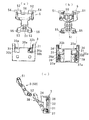
- the base member 3 has a substantially rectangular plate shape that fits in the recess 14 and corresponds to the substantially U-shaped central portion 30 and the U-shaped opposite sides of the central portion 30 as shown in FIGS. 4 and 5A to 5C. And side walls 31 and 31 connected via the connecting portions 33a and 33b.
- the window 35a penetrated back and forth is provided below the one connection part 33a. Below the other connecting portion 33b, two small windows 35b opened forward and backward are provided. That is, as shown in FIG. 5A, the window 35a is formed as a rectangular cavity which is penetrated back and forth on the lower side of the connecting portion 33a, and the bottom surface 30b of the cavity is communicated with the front and back.
- the window 35b is provided as a rectangular cavity (the bottom surface 30b of this cavity is not communicated back and forth) which is notched from the front to near the back on the lower side of the connecting portion 33b. It is closed and formed on its back.
- each side wall 31 is provided on the outer surface and is in engagement with the ridge portion 17 with the groove 32, the projection 34 for projecting to the upper rear side and fitting to the overhang 14b, the installation provided on the lower rear side It has a hole 39.
- Each side wall 31 has a pin insertion hole 36 located on the upper side of the groove 32 and passing through the left and right coaxial lines, and a shaft hole located on the inner lower side and passing through the left and right coaxial lines from the inner surface to the groove 32 And 37.
- Reference numeral 37a is a guide groove when the shaft 55 of the second link member described later is fitted into the hole 37.
- the first link member 4 and the second link member 5 are rotatably supported on the base member 3. That is, as shown in FIG. 5C, the first link member 4 has a substantially rectangular shape in a side view, and the outer surface side is a design surface and the inner surface side is an urging member disposition portion. In terms of shape, it has an upper plate portion 40, and leg portions 41 and 41 projecting obliquely downward from both lower sides of the plate portion 40.
- the plate portion 40 is provided with shafts 44, 44 coaxially protruding on both upper sides, holes 45, 45 coaxially penetrating on the lower both sides, and supporting shafts provided in the left and right opposite directions on the inner both sides. Portions 46 and 46 are provided.
- leg 41 one is disposed in the cavity forming the window 35a described above, and the other is disposed in the cavity in front of the surface forming the small window 35b.
- Reference numeral 47 denotes a guide groove provided in the middle of the lower end of one leg 41.
- the pins P are inserted from the base member side insertion holes 36.
- a torsion coil spring is incorporated as the biasing member 6.
- the winding portion (coil portion) 6a is slightly longer than the distance between the support shaft portions 46 of the base member.
- the first end b of the first end b is bent in a substantially U shape at the end 6b side, and the first b1 connected to the winding portion 6a, the second b2 bent in the L shape from the first b1 b, the second It consists of the 3rd node b3 bent to L form from b2.
- the other end 6c is bent in the shape of one piece forming a wedge shape at the tip end portion, and the first section c1 and the first section b1 connected to the winding portion 6a
- the second section c2 is bent in an L shape, and the third section c3 is bent approximately in parallel to the first section c1 from the second section c2.
- the third node b3 of one end 6b is directed to the direction of the winding portion 6a, but the third node c3 of the other end 6c is directed to the direction away from the winding portion 6a.
- the above biasing member 6 is stably supported inside the first link member 4 in a state in which both sides of the winding portion 6 a are fitted to the corresponding support shaft portions 46.
- the first node b1 and the second node b2 are disposed on the front side with respect to the front side cavity on the small window 35b side, and the third node b3 passes through the guide groove 47 from the inner surface 41b side of the corresponding leg 41 It is pulled out in the direction along the 41a side.
- the other end 6c is in contact with the inner surface 41b of the leg 41 to which the first node c1 corresponds, the second node c2 is disposed in the window 35a from the front cavity, and the third node c3 is along the window frame end face of the window 35a It is pulled downward.
- one end 6b is in contact with the outer surface 41a of the corresponding leg 41 from the cavity of the small window 35b at the tip (third node b3).
- the other end 6c is in contact with the inner surface 41a of the leg portion 41 corresponding to the first node c1;
- the leg portion 41 is strongly pressed, and as shown in FIG. 9, the second node c2 and the first node c3 are largely projected outward from the window 35.
- the other end 6c accumulates a biasing force between the second node c2 and the winding portion 6a.
- the second link member 5 is a projection projecting from both sides of the wide upper portion 50, the narrow thin portion 51, and the upper portion 50 as shown in FIGS. 4 and 6 (a) to (c). 52 and 52, respectively.
- a shaft 54 is provided on the outer surface of each protrusion 52 so as to protrude coaxially.
- Shafts 55 are provided on the outer side surfaces of the lower portion 51 so as to project coaxially.
- each protrusion 52 is disposed between the arm 22 and the arm 22 of the lid with respect to the lid main body 20, and the shaft 54 rotatably corresponds to the corresponding hole 26. It is fitted. Also, the lower shafts 55 are rotatably fitted and connected to the corresponding holes 37 of the base member.
- the groove 32 on both sides of the recess 14 of the housing is a protrusion It is pushed in so that it may be fitted in the part 17.
- the base member 3 is positioned when the projection 34 on the back side is in contact with the restricting projection 14 b and is attached to the recess 14 by the engagement of the projection 17 and the groove 32.
- the base member 3 is fastened and fixed by a fastener such as a screw (not shown) as necessary.
- the stopper is screwed into the mounting hole 14 c and the mounting hole 39 of the base member from the outside of the housing 1.
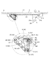
- the lid 2 is switched between the closed position shown in FIGS. 1A and 7 in which the lid 2 is substantially flush with the body B of the vehicle body and the fully open position shown in FIGS.
- the lid 2 is locked by the locking member against the biasing force stored between the winding portion 6 a and the end 6 b of the biasing member 6.
- one end 6b of the biasing member is in contact with the outer surface 41a of the corresponding leg 41 from the cavity of the small window 35b at the tip (third node b3).
- the first link member 4 is turned in the direction approaching the lid body 20, that is, in the counterclockwise direction.
- the first end b and the second end b 2 are not in contact with the base member side, and the third end b 3 is in contact with the outer surface 41 a of the one leg 41 which is the pop-up contact portion.
- the contact portion becomes a force point and accumulates a biasing force with the winding portion 6a.
- the lid 2 is stably held in a closed position locked by the lock member by the accumulated biasing force.
- the other end 6c is in contact with the lower back surface of the window 35a that is penetrated in the front and rear direction below the connecting portion 33a (spring fixing point).
- the lock member is engaged with the lock hole 24a at the closed position of the lid 2 so as to lock the lid 2 in the closed state, and the lock is retracted and the lid 2 can be rotated in the opening direction.
- the lid 2 is pivoted to the first reference position by the biasing force stored in the biasing member 6 when the lock is released.
- the lid 2 In this first reference position, the lid 2 is slightly lifted from the opening of the body of the vehicle body, and the user places the tip of the hand in the gap formed with the body B as shown by the alternate long and short dash line It is in a state where it can be turned.
- the biasing member 6 In this state, in the biasing member 6, the first node b1 of one end 6b abuts (fixing point) on the connecting portion 33b, and the other end 6c abuts on the lower back surface of the window 35a (spring fixing point) Therefore, it is held in the half open state.
- FIG. 9 shows a state in which the lid 2 is rotated from the first reference position of FIG. 8 to the second reference position set in the opening direction.
- the other end 6c is moved into the cavity of the leg 41 while the first node c1 is in contact with the corresponding inner surface 41b of the leg as described above.
- the second section c2 and the first section c3 are greatly projected outward from the window 35 as shown in FIG.
- a predetermined biasing force is accumulated at the other end 6c, particularly between the second node c2 and the winding portion 6a.
- the lid 2 when the lid 2 is rotated from the first reference position to the second reference position against the biasing force, thereafter, the second node c2 and the winding portion 6a are The lid 2 is automatically made pivotable from the second reference position to the fully open position by the biasing force accumulated therebetween. Also, when the lid 2 is rotated from the fully open position to the second reference position, the biasing direction is reversed, and thereafter the lid 2 can be automatically rotated from the second reference position to the first reference position. .
- the lid 2 is opened and closed by the rotation through the first and second link members 4 and 5, so that the movement of the lid can be made compact;
- the second link member 5 is sandwiched between the lid 2 and the first link member 4 in that the upper portion 50 of the second link member 5 is in contact with the inner side of the first link member 4.
- the first link member 5 has a flat design surface between the legs 22 and so on, which is visually superior.
- the housing 1, the lid 2 (the lid body 20 and the lid outer 27), the base member 3, the first link member 4 and the second link 5 are made of resin and therefore excellent in mass productivity. At the same time, it is easy to reduce the weight.
- the symbol F1 indicates the biasing direction to the lid
- the symbol F2 indicates a spring load
- the symbol PP1 indicates a force point (a pop-up contact portion, one leg 41 or The outer surface 41a) is shown
- the symbol SP1 indicates the spring fixing point (the first contact portion for the biasing member of the base member corresponding to the contact portion for pop-up, the lower back surface of the window 35a)
- the symbol S Show a gap.
- the symbol SP2 indicates a spring fixing point (a second abutment for the biasing member of the base member corresponding to the abutment for the deadlock, the front side of the connecting portion 33a), and a symbol PP2 Shows the point of force (the abutment for the deadlock, the other leg 41 or its outer surface 41b).
- the lid device is substantially in the form of a substantially open container which defines the space 12 as in the first embodiment of the present invention.
- the housing 1 a lid 2 for opening and closing the upper opening of the housing 1, a base member 3A mounted around the inner periphery of the housing 1, and a link member for supporting the lid 2 openably and closably with respect to the base member 3A
- a second link member 7, 8 and a biasing member 9 disposed between the two link members 7, 8, the lid 2 relative to the housing 1 via a base member 3A and two link members 7, 8 Is rotatably supported.
- the lid 2 is locked at the closed position shown in FIG.
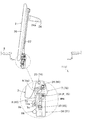
- the base member 3A is in the form of a substantially rectangular plate that fits in the recess 14, and as shown in FIG. 11 and FIGS. 12 (a) to 12 (c), the end portion of both sides It has side walls 31 and 31 integrated in the portion through connecting portions 33a and 33b and the like, and recesses 38 provided on the back side and provided on the lower sides of the central portion 30.
- a predetermined gap is maintained between the front wall of the central portion 30 and the side walls 31, and the lower sides of the connection portions 33a and 33b are penetrated through the window 35 in the back and forth direction.
- Each window 35 is a rectangular cavity which is penetrated back and forth on the lower side of the connecting portions 33a and 33b.
- Reference numeral 30 b is an inner bottom surface of the window 35.
- Reference numeral 33c is a guide groove which is provided on the front side of the connecting portion 33b and which can come in contact with a portion between a winding portion 9a and one end 9b side of the biasing member described later.
- each recess 38 is located on the lower sides of the central portion 30. As shown in FIG. 12 (b), the recess 38 on the left side is separated from the window 35 via a lateral wall. On the other hand, the recess 38 on the right side is in communication with the window 35 via the vertical groove 30c.
- the longitudinal groove 30c allows the other end 9c of the biasing member described later to project from the gap between the front wall of the central portion 30 and the corresponding side wall 31 into the recess 38 on the right side.
- the recess 38 on the right side is communicated with the front wall of the central portion 30 which is lowered by one step through the notch portion 38a with a slight level difference.
- the cutout 38 a enables the projection 73 of the second link member 8 described later to be disposed in the recess 38.
- Each side wall 31 is provided on the outer surface and is engaged with the ridge 17 of the housing, the groove 32 is engaged with the ridge 17 of the housing, and the position projection 34 is provided on the lower rear surface.
- a mounting hole 39 is provided.
- a pin insertion hole 36 which is penetrated on the left and right coaxial line is provided.
- the inner wall defining the window 35 is provided with an axial hole 37 penetrating on the left and right coaxial line.
- the first link member 7 and the second link member 8 are rotatably supported on the base member 3A. That is, the first link member 7 is substantially shaped in a side view, the outer surface side is a design surface, and the inner surface side is an urging member disposition portion. In terms of shape, it has an upper plate portion 70, and legs 72, 72 projecting obliquely downward from the lower sides of the plate portion 70.
- the plate portion 70 includes shafts 74 and 74 coaxially protruding on both upper sides, holes 75 and 75 coaxially penetrating on both sides, and support shaft portions provided in a state in which the inner sides are horizontally opposed to each other. 76 and 76 are provided.
- An overhanging portion 73 is provided on the inner lower end surface on one side of the leg portion 72.
- the overhanging portion 73 is provided with a loose fitting hole 73a which is penetrated in the left-right direction.
- the other side of the leg portion 72 is provided with a step portion 72a which is formed one step lower and holds a portion between the other end 9c of the biasing member and the winding portion 9a.
- the pin P is inserted into the base member side insertion hole 36 in a state where the holes 75 on both sides of the base member 3A overlap the corresponding insertion holes 36 of the base member as shown in FIG. And the hole 75 is rotatably fitted.
- a torsion coil spring is incorporated as the biasing member 9.
- the winding portion (coil portion) 9a is slightly longer than the distance between the support shaft portions 76 of the base member.
- the tip end portion of the one end 9b side is bent into a substantially L shape.
- the other end 9c has a tip portion projecting obliquely downward.
- the biasing member 9 is stably supported on the inside of the first link member 7 in a state in which both sides of the winding portion 9a are fitted to the corresponding support shaft portions 76.
- the end of the one end 9b passes through the vertical groove 30c, and the tip end is inserted into the loose fitting hole 73a of the overhanging portion.
- the other end 9c is rockably inserted from the upper rear surface of the first link member through the vertical hole 30c into the corresponding recess 38.
- the second link member 8 has a projection which protrudes from the upper and lower sides of the wide upper part 80, the narrow thin part 81, and the upper part 80 as shown in FIGS. 11 and 13 (a) to (c). It comprises a portion 82 82 and a bent portion 83 projecting obliquely downward from the lower portion 81.
- a shaft 84 is coaxially provided on the outer surface of each protrusion 82.
- a shaft 85 is coaxially provided on both outer side surfaces of the lower portion 81.
- a projecting portion 86 is provided at a right angle on one side of the bent portion 83.
- each protrusion 82 is disposed between the arm 22 and the arm 22 of the lid relative to the lid body 20, and the shaft 84 is rotated in the corresponding hole 26 of the lid body 20. It is fitted freely.
- the lower shafts 85 are rotatably fitted and connected to the corresponding holes 37 of the base member.
- the overhanging portion 86 is disposed in the recess 38 from the notch 38a. In this state, as shown in FIGS. 14 to 17, the other end 9c of the biasing member can abut on the outer surface of the overhanging portion 86 or can be detached from the overhanging portion 86 and abut on the first link member side step portion 72a. It has become.
- the second link member 8 swings in the process of pivoting with the pivoting portion of the shaft 85 and the hole 37 as a fulcrum, and a biasing force is accumulated between the other end 9c and the winding portion 9a.
- the accumulated biasing force can be used as a movable biasing force for the link members 7 and 8, ie, a deadlock.
- the groove 32 on both sides of the base member 3A protrudes from the recess 14 of the housing. It is pushed in so that it may be fitted in the strip 17. Then, the base member 3 is positioned when the projection 34 on the back side is in contact with the restricting projection 14 b and is attached to the recess 14 by the engagement of the projection 17 and the groove 32.
- the base member 3 is fastened and fixed by a fastener such as a screw (not shown) as necessary. In this operation, the stopper is screwed into the mounting hole 14 c and the mounting hole 39 of the base member from the outside of the housing 1.
- one end 9b of the biasing member is fitted in the loose fitting hole 73a of the first link member side overhang portion 73, and It is in contact with the corresponding inner end face of a certain loose fitting hole 73a. Then, in the process of turning the lid 2 from the first reference position shown in FIG. 15 to the closed position shown in FIG. 14, the first link member 7 moves in the direction approaching the lid main body 20, that is, in the counterclockwise direction. Be done. Then, the one end 9b is also pushed by the corresponding inner end face of the loose fitting hole 73a, and a biasing force is accumulated between the end 9b and the winding portion 9a.
- the lid 2 is stably held in a closed position locked by the lock member by the accumulated biasing force.
- the other end 9c is in contact with the outer surface of the overhanging portion 86 of the second link member (spring fixing point).
- the lock member is engaged with the lock hole 24a at the closed position of the lid 2 so as to lock the lid 2 in the closed state, and the lock is retracted and the lid 2 can be rotated in the opening direction.
- FIG. 15 shows a state in which the lid 2 is pivoted to the first reference position by the biasing force accumulated in the biasing member 9 when the lock is released.
- the lid 2 In this first reference position, the lid 2 is slightly raised above the opening of the body B of the vehicle body, and the user places the tip of the hand in the gap formed between the lid 2 and the body B as shown by the alternate long and short dash line It is in a state where it can be turned to the In this state, the winding portion 9a and the one end 9b of the biasing member 9 come into contact with the guide groove 33c of the base member to be stationary, and the one end 9b corresponds to the corresponding inner end face of the first link member loose fitting hole 73a. , And the other end 9c abuts on the outer surface of the second link member side overhanging portion 86 (spring fixing point), so that it is held in the half-opened state of FIG.
- the one end 9b is elastically displaced with the contact portion as a fulcrum.
- FIG. 16 shows a state in which the lid 2 is rotated from the first reference position shown in FIG. 15 to the second reference position where the lid 2 is further set in the opening direction.
- the space between the winding portion 9a and the other end 9c is pressed by the step portion 72a of the first link member.
- a predetermined biasing force is accumulated between the other end 9c and the winding portion 9a.
- the lid 2 is rotated from the first reference position to the second reference position against the biasing force. Then, as shown in FIG. 17, when the second reference position in FIG. 16 is passed, thereafter, the lid 2 is automatically made pivotable to the fully open position by the biasing force accumulated on the other end 9c side. .
- the code PP3 indicates the power point (the pop-up contact portion, the overhang portion 73 of the first link member 7), and the code SP3 indicates the spring fixing point (pop-up contact portion
- the first contact portion of the second link member corresponding to the second link member shows the overhanging portion 86) of the second link member, and the symbol SP4 corresponds to the spring fixing point (corresponding to the pop-up contact portion).
- the first contact portion for the biasing member of the first link member indicates the step portion 72a) of the first link member
- the symbol SP4 indicates a spring fixing point (a base member corresponding to the contact portion for deadlock).
- the second contact portion for the biasing member indicates the guide groove 33c
- the symbol SP5 indicates a spring fixing point (a second contact portion for the biasing member of the first link member corresponding to the contact portion for deadlock).
- reference numeral PP4 indicates a power point (a step portion 72a of the first link member at the abutment portion for deadlock).
- the lid device described above can be variously modified except for the requirements specified in the claims.
- the lid 2 can also be formed integrally with the outer lid 27 on the lid body 20.
- the first link member 4 or 7 has a hole 45 or 75 so that the pin P is mounted from the insertion hole 36 of the base member 3 to the hole 45 or 75 using the pin P which is the shaft.
- a shaft such as the shaft 44 may be provided to directly fit into the holes provided corresponding to the holes 45 or 75 from the insertion holes 36 on the base member side.
Abstract
This lid device for vehicle comprises a link member which supports, by linking to a housing, a lid so as to be able to open and close; and a biasing member which can move the lid from a fully-closed position to a first reference position which is a partly-open position, by means of biasing force, and which can move the lid from a second reference position which is further in the open direction than the first reference position to a fully-open position, by means of biasing force. The link member comprises a first link member and a second link member which are pivotably supported at one end on the rear side of the lid, and pivotably supported at the other end within the housing. The biasing member has a pop-up contact part (leg outer surface) for switching the lid from the closed position to the first reference position, and a deadlock contact part (leg inner surface) inner surface for switching between biasing towards the first reference position and biasing towards the fully open position, with the second reference position in between.
Description
本発明は、車両のリッド装置に関する。
The present invention relates to a lid device of a vehicle.
図18(a)(b)及び図19は下記特許文献1に開示された車両のリッド装置を示している。このリッド装置1は、給油口等を配置するハウジング(ソーサー)2と、開口2aを開閉するリッド(蓋部材)3と、リッド3に延設されてハウジング2に対しリッド3を連結支持するアーム3bと、リッド3を閉位置から開途中である第1基準位置まで付勢力によりポップアップしたり、また、更に開方向にある第2基準位置を挟んで閉じ方向である第1基準位置への付勢と全開位置への付勢を切り換える(以下、これをデッドロックという)ための付勢手段であるばね5とを有している。
18 (a), (b) and 19 show a lid device of a vehicle disclosed in Patent Document 1 below. The lid device 1 includes a housing (sorter) 2 for disposing a filler port and the like, a lid (lid member) 3 for opening and closing the opening 2 a, and an arm extended to the lid 3 and connecting and supporting the lid 3 to the housing 2 3b, the lid 3 pops up from the closed position to the first reference position which is in the process of opening, or is attached to the first reference position which is the closing direction across the second reference position which is further in the opening direction. It has a spring 5 which is biasing means for switching between biasing and biasing to the fully open position (hereinafter referred to as a deadlock).
ハウジング2は、筒状部2b及び筒状部に連設された水平延長部2cを備える。リッド3は、開口2aを開閉する蓋本体3a及びグースネックタイプのアーム3bからなる。アーム3bは、水平延長部2c内に配置されてピン4により回動可能に軸支される。符号3cはばね5(後述する弾性変形部5c)が当接する当接部である。ばね5は、図11(b)のごとく上下方向へ延び水平延在部2cに固定される本体側固定部5aと、該固定部5aの下端から水平方向に延びる本体側水平部5bと、該水平部5bのリッド側の端部から上方へ延びる弾性変形部5cと、弾性変形部5cの上端から水平方向へ延びるリッド側水平部5dと、その水平部5dのリッド側の端部から下方へ延びてアーム部3bに固定されてアーム部と共に移動するリッド側固定部5eとを有している。また、弾性変形部5cは、水平部5bの端部から斜め上方へ延びる斜め延在部5c1と、リッド側水平部5dの端部から下方へ延びる上下延在部5c2とからなる。符号5fは、本体側水平部5aの上端から水平方向に延びる折り返し部である。
The housing 2 is provided with a cylindrical portion 2 b and a horizontal extension portion 2 c connected to the cylindrical portion. The lid 3 comprises a lid body 3a for opening and closing the opening 2a and an arm 3b of gooseneck type. The arm 3 b is disposed in the horizontal extension 2 c and pivotally supported by the pin 4. The code | symbol 3c is a contact part which the spring 5 (elastic deformation part 5c mentioned later) contact | abuts. The spring 5 extends in the vertical direction as shown in FIG. 11B and is fixed to the horizontally extending portion 2c, the body side fixing portion 5a, the body side horizontal portion 5b extending in the horizontal direction from the lower end of the fixing portion 5a, and An elastic deformation portion 5c extending upward from the end of the horizontal portion 5b on the lid side, a lid side horizontal portion 5d extending horizontally from the upper end of the elastic deformation portion 5c, and a lid side end of the horizontal portion 5d downward And a lid side fixing portion 5e which is fixed to the arm portion 3b and moves together with the arm portion. The elastically deformable portion 5c includes an obliquely extending portion 5c1 which extends obliquely upward from the end of the horizontal portion 5b, and a vertically extending portion 5c2 which extends downward from the end of the lid-side horizontal portion 5d. The code | symbol 5f is a folding | returning part extended in a horizontal direction from the upper end of the main body side horizontal part 5a.
以上のばね5は、本体側固定部5aが水平延在部2cに固定され、リッド側固定部5eがアーム部3bに固定された状態に組み込まれ、リッド3に対し伸縮方向の付勢力を加えた状態となる。また、ばね5は、リッド3の回転位置によっては、伸縮方向の付勢力(この付勢力を『第2付勢力』という)の他、伸縮方向と略直角な方向の付勢力(この付勢力を『第1付勢力』という)をリッド3に加える場合がある。すなわち、この構造では、弾性変形部5cがリッド3の閉塞方向への押し込みにより弾性変形し、ばね5からリッド3を開放方向へ付勢するポップアップ用第1付勢力が作用する(第1付勢部)。また、リッド固定部5eがリッド3の回転中心(ピン4)と本体側固定部5aを結ぶ仮想線100よりも、閉塞側であると第2付勢力はリッド3を閉塞する方向へ作用し、開放側であると第2付勢力はリッド3を開放する方向へ作用する。つまり、ばね5は、第1基準位置を超えた第2基準位置までリッド3を閉塞方向へ付勢し、第2基準位置から全開位置までリッド3を開放方向へ付勢するデッドロック用として作用する。
The spring 5 described above is incorporated in a state in which the body side fixing portion 5a is fixed to the horizontal extension portion 2c and the lid side fixing portion 5e is fixed to the arm portion 3b, and an urging force in the expansion and contraction direction is applied to the lid 3 It will be Further, depending on the rotational position of the lid 3, the spring 5 has an urging force in the expansion / contraction direction (this urging force is referred to as a “second urging force”) and an urging force in a direction substantially perpendicular to the expansion / contraction direction (this urging force There is a case in which “the first biasing force” is added to the lid 3. That is, in this structure, the elastically deforming portion 5c is elastically deformed by pushing the lid 3 in the closing direction, and the pop-up first biasing force acts to bias the lid 3 from the spring 5 in the opening direction (first biasing Department). In addition, the second biasing force acts in the direction of closing the lid 3 if the lid fixing portion 5e is at the closing side than the imaginary line 100 connecting the rotation center (pin 4) of the lid 3 and the main body side fixing portion 5a. In the open side, the second biasing force acts in the direction of opening the lid 3. That is, the spring 5 acts as a deadlock for urging the lid 3 in the closing direction to the second reference position beyond the first reference position and urging the lid 3 in the opening direction from the second reference position to the fully open position. Do.
従って、リッド装置としては、リッドが閉位置で不図示のロック機構により係止されており、ロック機構のロック解除によりばねの第1付勢力により第1基準位置まで回動される。その後は、リッドが第2基準位置まで回動操作されると、第2基準位置からばねの第2付勢力により全開位置まで回動されることとなる。
Therefore, as the lid device, the lid is locked by the lock mechanism (not shown) in the closed position, and is rotated to the first reference position by the first biasing force of the spring when the lock mechanism is unlocked. Thereafter, when the lid is turned to the second reference position, the lid is turned from the second reference position to the fully open position by the second biasing force of the spring.
上記リッド装置では、第2付勢力がばねの伸縮方向の弾性力により付与され、第1付勢力がその伸縮方向と略直角な方向の弾性力により付与されるようにして、単一のばねにより異なる2方向の付勢力を独立して発生させ、それによりスペース効率を良好にすると共に、各部品のレイアウトの自由度を向上できるとある。ところが、このような構造では、リッドが全開位置でハウジングから離間して意匠性を損ねたり、ハウジングが水平延在部の存在でコンパクト化し難い。また、リッド組付け操作では、アームが水平延在部の内奥側に挿入された状態でピン等で枢支したり、ばねが本体側固定部を水平延在部内の決められた箇所に係止しなければならず作業性が悪い。
In the lid device described above, the second biasing force is applied by the elastic force in the expansion and contraction direction of the spring, and the first biasing force is applied by the elastic force in the direction substantially perpendicular to the expansion and contraction direction. It is possible to generate biasing forces in two different directions independently, thereby improving space efficiency and improving the freedom of layout of each part. However, in such a structure, the lid is separated from the housing at the fully open position to impair the design, and the housing is difficult to be compact due to the presence of the horizontally extending portion. Further, in the lid assembling operation, the arm is pivotally supported by a pin or the like in a state inserted into the inner back side of the horizontal extension, or a spring engages the main body side fixing portion at a predetermined position in the horizontal extension. It must be stopped and the workability is bad.
本発明の目的は、以上の課題を解決して、リッドをポップアップ用とデッドロック用の付勢力により移動する構造において、ハウジングのコンパクト化を可能にしたり意匠性に優れた車両のリッド装置を提供する。また、リッド組付け操作性も良好に行えるようにする。他の目的は以下の内容説明のなかで明らかにする。
SUMMARY OF THE INVENTION The object of the present invention is to solve the above problems and provide a lid device of a vehicle which enables a compact housing and is excellent in design in a structure in which a lid is moved by a biasing force for pop-up and deadlock. Do. In addition, the lid assembly operability can be favorably performed. Other objectives will be clarified in the following content description.
上記目的を達成するため本発明の第1態様では、開口内部に給油口又は電気充電口を配置するハウジングと、前記ハウジングの開口を開閉するリッドと、前記リッドを前記ハウジングに開閉可能に連結支持するリンク部材と、前記リッドを閉位置から開途中である第1基準位置まで付勢力により移動可能、かつ第1基準位置より更に開方向にある第2基準位置から全開位置まで付勢力により移動可能にする付勢部材とを有した車両のリッド装置であって、前記リンク部材は一端側が前記リッドの裏側に枢支され、他端側が前記ハウジング内に設けられるベース部材に枢支される第一のリンク部材及び第二のリンク部材からなると共に、前記付勢部材が前記リッドを閉位置から第1基準位置へ切り換えるためのポップアップ用当接部(リッドの跳ね上げつまりポップアップの際に付勢部材が力点として接触する当接部という意味である、以下同じ。例えば、本発明の第1実施形態では第一のリンク部材の一方の脚部、第2実施形態では第一のリンク部材7)、及び第2基準位置を挟んで第1基準位置への付勢と全開位置への付勢を切り換えるためのデッドロック用当接部(付勢方向の切換つまりデッドロックの際に付勢部材が力点として接触する当接部という意味である、以下同じ。例えば、本発明の第1実施形態では第一のリンク部材の脚部(他方の脚部)、本発明の第2実施形態では第一のリンク部材7の段差部72a)を有していることを特徴としている。
In order to achieve the above object, according to a first aspect of the present invention, there is provided a housing in which an oil filler or electric charging port is disposed inside an opening, a lid for opening and closing the opening of the housing, and a connection support for opening and closing the lid Link member and the lid can be moved from the closed position to the first reference position which is in the process of opening by the biasing force, and can be moved by the biasing force from the second reference position which is further in the opening direction than the first reference position And the link member is pivotally supported at one end thereof on the back side of the lid and at the other end thereof on a base member provided in the housing. And a second link member, wherein the biasing member causes the lid to switch from the closed position to the first reference position. The same applies to an abutment where the biasing member contacts as a point of force in the case of popping up or popping up, for example, in the first embodiment of the invention one leg of the first link member, second embodiment In the embodiment, the first link member 7), and the abutment portion for deadlock for switching the biasing to the first reference position and the biasing to the fully open position across the second reference position (switching of the biasing direction In the event of a deadlock, this means the abutment where the biasing member contacts as a point of force, for example, in the first embodiment of the present invention, the leg of the first link member (the other leg), the main part The second embodiment of the present invention is characterized in that the step portion 72a) of the first link member 7 is provided.
本発明の第1態様では、リッドを閉位置から第1基準位置に跳ね上げるポップアップ用の付勢力及び第2基準位置から全開位置への付勢と第1基準位置への付勢を切り換えるためのデッドロック用の付勢力を単一の付勢部材により得られることに加え、各形態例から明らかなごとく2つのリンク部材によりリッドの動きを制御してコンパクト化を図ったり、ハウジングに内設されるベース部材により付勢部材の組付け及びハウジングへの組付けを簡易化できる。
In the first aspect of the present invention, a biasing force for pop-up that lifts the lid from the closed position to the first reference position and a bias for switching the biasing from the second reference position to the fully open position and the bias to the first reference position In addition to the fact that the biasing force for the deadlock is obtained by a single biasing member, the movement of the lid is controlled by two link members as is apparent from each embodiment to achieve compactness or to be installed in the housing. Can simplify the assembly of the biasing member and the assembly to the housing.
以上の本発明は、下記の第2~5態様で特定するように具体化してもよい。
(第2態様)前記付勢部材は、前記第一のリンク部材と前記ベース部材の間に配置されており、前記ポップアップ用当接部は前記第一のリンク部材のリッド側に配される箇所(例えば、後述する、一方の脚部外面41a)であると共に、前記デッドロック用当接部は前記第一のリンク部材のベース部材側に配される箇所(例えば、後述する、他方の脚部内面41b)である。これは、後述する本発明の第1実施形態に基づいた特定である。 The present invention as described above may be embodied as specified in the following second to fifth embodiments.
(Second Mode) The biasing member is disposed between the first link member and the base member, and the pop-up contact portion is disposed at the lid side of the first link member. (For example, one legouter surface 41a described later, and the deadlock abutment portion is disposed on the base member side of the first link member (for example, the other leg described later) It is an inner surface 41b). This is a specification based on the first embodiment of the present invention described later.
(第2態様)前記付勢部材は、前記第一のリンク部材と前記ベース部材の間に配置されており、前記ポップアップ用当接部は前記第一のリンク部材のリッド側に配される箇所(例えば、後述する、一方の脚部外面41a)であると共に、前記デッドロック用当接部は前記第一のリンク部材のベース部材側に配される箇所(例えば、後述する、他方の脚部内面41b)である。これは、後述する本発明の第1実施形態に基づいた特定である。 The present invention as described above may be embodied as specified in the following second to fifth embodiments.
(Second Mode) The biasing member is disposed between the first link member and the base member, and the pop-up contact portion is disposed at the lid side of the first link member. (For example, one leg
本発明の第2態様では、付勢部材が第一のリンク部材とベース部材の間に配置されていると共に、第一のリンク部材がポップアップ用当接部とデッドロック用当接部を反対側の面に有しているため、簡明であり良好な加工性及び組立性を維持可能となる。
(第3態様)前記付勢部材は、前記第一のリンク部材と前記第二のリンク部材の間に配置されており、前記ポップアップ用当接部は前記第一のリンク部材の所定箇所(例えば、後述する張出部73)であると共に、前記デッドロック用当接部は前記第一のリンク部材の所定箇所(例えば、後述する段差部72a)である)。これは、本発明の第2実施形態に基づいた特定である。 In the second aspect of the present invention, the biasing member is disposed between the first link member and the base member, and the first link member is opposite to the contact portion for pop-up and the contact portion for deadlock. As a result, it is possible to maintain simplicity and good processability and assemblability.
(Third Aspect) The biasing member is disposed between the first link member and the second link member, and the pop-up contact portion is a predetermined portion (for example, the first link member). In addition to theoverhang portion 73 described later, the deadlock contact portion is a predetermined portion of the first link member (for example, a step portion 72a described later). This is a specification based on the second embodiment of the present invention.
(第3態様)前記付勢部材は、前記第一のリンク部材と前記第二のリンク部材の間に配置されており、前記ポップアップ用当接部は前記第一のリンク部材の所定箇所(例えば、後述する張出部73)であると共に、前記デッドロック用当接部は前記第一のリンク部材の所定箇所(例えば、後述する段差部72a)である)。これは、本発明の第2実施形態に基づいた特定である。 In the second aspect of the present invention, the biasing member is disposed between the first link member and the base member, and the first link member is opposite to the contact portion for pop-up and the contact portion for deadlock. As a result, it is possible to maintain simplicity and good processability and assemblability.
(Third Aspect) The biasing member is disposed between the first link member and the second link member, and the pop-up contact portion is a predetermined portion (for example, the first link member). In addition to the
本発明の第3態様では、第2態様に比べ、付勢部材が2つのリンク部材の間に配置されているため第二のリンク部材も常にがたつきなく支持可能となり、加えてポップアップ用当接部が第一のリンク部材の所定箇所、デッドロック用当接部が第一のリンク部材の所定箇所であることから、設計自由度を拡大できる。
In the third aspect of the present invention, as compared with the second aspect, since the biasing member is disposed between the two link members, the second link member can also be supported constantly without rattle, and additionally, the pop-up Since the contact portion is a predetermined portion of the first link member and the deadlock contact portion is a predetermined portion of the first link member, the degree of freedom in design can be expanded.
(第4態様)前記ベース部材は、前記ポップアップ用当接部に対応した付勢部材用第一当接部(例えば、後述する窓35a)、及び前記デッドロック用当接部に対応した付勢部材用第二当接部(例えば、後述する連結部33b)を有している構成である。これは、本発明の第1実施形態に基づいた特定である。
(Fourth Aspect) The base member is a biasing member first contact portion (for example, a window 35a described later) corresponding to the pop-up contact portion, and a biasing member corresponding to the deadlock contact portion It is the structure which has the 2nd contact part for members (for example, the connection part 33b mentioned later). This is a specification based on the first embodiment of the present invention.
本発明の第4態様では、第2態様において、ベース部材がポップアップ用当接部に対応した付勢部材用第一当接部、及びデッドロック用当接部に対応した付勢部材用第二当接部を有しているため、例えばベース部材、2つのリンク部材、付勢部材の組立体とした状態から、リッドに連結し、最後にハウジングに組み入れ可能となる。
(第5態様)前記付勢部材用第一当接部は前記ベース部材の前記第二のリンク部材側に配された面(例えば、後述する窓35aの下側背面)であると共に、前記付勢部材用第二当接部は前記ベース部材の前記第一のリング部材側に配された面(例えば、後述する連結部33bの正面側)である構成である。 In a fourth aspect of the present invention, in the second aspect, the base member is a first contact portion for the biasing member corresponding to the contact portion for pop-up, and a second for the biasing member corresponding to the contact portion for deadlock. Due to the presence of the contact portion, for example, from the assembled state of the base member, the two link members, and the biasing member, it can be connected to the lid and finally be incorporated into the housing.
(Fifth Aspect) The first contact portion for biasing member is a surface (for example, a lower back surface of awindow 35a described later) disposed on the side of the second link member of the base member, and The second contact portion for a biasing member is a surface (for example, the front side of a connecting portion 33b described later) disposed on the first ring member side of the base member.
(第5態様)前記付勢部材用第一当接部は前記ベース部材の前記第二のリンク部材側に配された面(例えば、後述する窓35aの下側背面)であると共に、前記付勢部材用第二当接部は前記ベース部材の前記第一のリング部材側に配された面(例えば、後述する連結部33bの正面側)である構成である。 In a fourth aspect of the present invention, in the second aspect, the base member is a first contact portion for the biasing member corresponding to the contact portion for pop-up, and a second for the biasing member corresponding to the contact portion for deadlock. Due to the presence of the contact portion, for example, from the assembled state of the base member, the two link members, and the biasing member, it can be connected to the lid and finally be incorporated into the housing.
(Fifth Aspect) The first contact portion for biasing member is a surface (for example, a lower back surface of a
本発明の第5態様では、付勢部材用第一当接部がベース部材の第二のリンク部材側に配された面、付勢部材用第二当接部がベース部材の第一のリング部材側に配された面であるため、簡明なものとなる。
In the fifth aspect of the present invention, the biasing member first contact portion is disposed on the second link member side of the base member, and the biasing member second contact portion is the first ring of the base member. Since it is a surface disposed on the member side, it is simple.
In the fifth aspect of the present invention, the biasing member first contact portion is disposed on the second link member side of the base member, and the biasing member second contact portion is the first ring of the base member. Since it is a surface disposed on the member side, it is simple.
(第6態様)前記第二のリンク部材は前記ポップアップ用当接部に対応した付勢部材用第一当接部(例えば、後述する張出部86の正面側)を有していると共に、前記ベース部材は前記デッドロック用当接部に対応した付勢部材用第二当接部(例えば、後述するガイド溝33c)を有している構成である。これは本発明の第2実施形態に基づく特定である。
(Sixth Aspect) The second link member has a first contact portion for biasing member (for example, the front side of the overhang portion 86 described later) corresponding to the contact portion for pop-up, and The base member has a biasing member second contact portion (for example, a guide groove 33 c described later) corresponding to the deadlock contact portion. This is a specification based on the second embodiment of the present invention.
本発明の第6態様では、第二のリンク部材がポップアップ用当接部に対応した付勢部材用第一当接部を有し、ベース部材がデッドロック用当接部に対応した付勢部材用第二当接部を有しているため、簡明なものとなる。
(第7態様)前記付勢部材は捻りコイルばねである。 In the sixth aspect of the present invention, the second link member has the first contact portion for the biasing member corresponding to the contact portion for pop-up, and the base member corresponds to the contact portion for the deadlock. Since it has the 2nd contact part, it becomes clear.
(Seventh Aspect) The biasing member is a torsion coil spring.
本発明の第7態様では、付勢部材が捻りコイルばねであるため、巻線部(コイル部)の両端を利用して必要な付勢力を容易に得ることができる。具体例としては、巻線部を利用して第一のリンク部材に支持した状態で、巻線部の一端側を利用してポップアップ用の付勢力を得るようにしたり、巻線部の他端側を利用して第2基準位置から第1基準位置への付勢及び第2基準位置から全開位置への付勢を得るようにする。
In the seventh aspect of the present invention, since the biasing member is a torsion coil spring, the necessary biasing force can be easily obtained by utilizing both ends of the winding portion (coil portion). As a specific example, in a state of being supported by the first link member using the winding part, a biasing force for pop-up is obtained using the one end side of the winding part, or the other end of the winding part The side is used to obtain a bias from the second reference position to the first reference position and a bias from the second reference position to the fully open position.
In the seventh aspect of the present invention, since the biasing member is a torsion coil spring, the necessary biasing force can be easily obtained by utilizing both ends of the winding portion (coil portion). As a specific example, in a state of being supported by the first link member using the winding part, a biasing force for pop-up is obtained using the one end side of the winding part, or the other end of the winding part The side is used to obtain a bias from the second reference position to the first reference position and a bias from the second reference position to the fully open position.
本発明の最良の実施形態について添付図面を参照しながら説明する。この説明では、本発明の第1実施形態のリッド装置の構造、その作動特徴、本発明の第2実施形態のリッド装置の構造、その作動特待の順で詳述する。
The preferred embodiments of the present invention will be described with reference to the attached drawings. In this description, the structure of the lid device according to the first embodiment of the present invention, the operation characteristics thereof, the structure of the lid device according to the second embodiment of the present invention, and the operation feature will be described in detail.
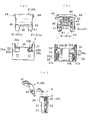
(本発明の第1実施形態の構造)図1(a)から図4において、この実施形態によるリッド装置は、給油口又は電気充填口用の空間12を区画している上開口した略容器状のハウジング1と、ハウジング1の上開口を開閉するリッド2と、ハウジング1の内周囲に装着されるベース部材3と、ベース部材3に対してリッド2を開閉可能に支持するリンク部材として第一及び第二のリンク部材4,5とを備え、リッド2がハウジング1に対しベース部材3と2つのリンク部材4,5を介して回動可能に支持されている。また、リッド2は、リッド本体20及び該リッド本体の意匠面に装着されるリッドアウタ27からなる。なお、材質は、ハウジング1、リッド本体20、リッドアウタ27、ベース部材3、第一のリンク部材4、第二のリンク5はそれぞれ樹脂製であるが、樹脂以外であってもよい。
(Structure of the First Embodiment of the Present Invention) In FIGS. 1 (a) to 4, the lid device according to this embodiment has a substantially container-like shape which is open at the top, which defines a space 12 for a filling port or an electric filling port. The housing 1, the lid 2 for opening and closing the upper opening of the housing 1, the base member 3 mounted on the inner periphery of the housing 1, and the link member for supporting the lid 2 openably and closably to the base member 3 And the second link members 4 and 5, and the lid 2 is rotatably supported on the housing 1 via the base member 3 and the two link members 4 and 5. Further, the lid 2 includes a lid main body 20 and a lid outer 27 mounted on a design surface of the lid main body. The housing 1, the lid body 20, the lid outer 27, the base member 3, the first link member 4 and the second link 5 are made of resin, but may be other than resin.
換言すると、リッド2は、ハウジング1の外周に装着されるロック手段Lのロック部材により図7で示した閉位置に係止される。この係止は、例えば、ロック手段Lが車室内のオープナーを介して係止解除操作されたり、ドアロックの解除操作と連動して係止解除される。すると、リッド2は、付勢部材6の付勢力により閉位置から図8のごとく少しだけ開く第1基準位置まで回動される。そして、リッド2を手などで開方向へ回動させると第2基準位置で付勢部材7の付勢方向が反転し、以後は図10のごとく付勢部材6の付勢力で同図の実線で示した全開方向へ回動される。細部は以下の通りである。
In other words, the lid 2 is locked in the closed position shown in FIG. 7 by the lock member of the lock means L mounted on the outer periphery of the housing 1. For example, the locking means L is released via the opener in the vehicle compartment or released in conjunction with the release operation of the door lock. Then, the lid 2 is rotated by the biasing force of the biasing member 6 from the closed position to the first reference position which opens slightly as shown in FIG. Then, when the lid 2 is pivoted in the opening direction by hand or the like, the biasing direction of the biasing member 7 is reversed at the second reference position, and thereafter the solid line in FIG. 10 is indicated by the biasing force of the biasing member 6 as shown in FIG. It is pivoted in the fully open direction indicated by. The details are as follows.
ハウジング1は、図3及び図1(a)(b)に示されるごとく筒状部10の上周囲が略矩形のフランジ部に形成され、該フランジ部の内側に設けられてリッド2を受け止める段差11、該フランジ部の外周囲に突設された複数の弾性係止爪10a、筒状部10の底壁に設けられた円形の貫通孔13、内周囲に設けられてベース部材3を配置可能な凹部14及び凹部14と奥側の傾斜面14a、傾斜部14aの両側に設けられた張出部14b、張出部14bに設けられた取付孔14c、段差11にあって張出部14bの上側に対応した箇所に設けられた浅い窪み部11a、内周囲にあって凹部14と対向する箇所に位置している深い窪み部15などを備えている。
As shown in FIGS. 3 and 1 (a) and 1 (b), the housing 1 is formed in a flange portion having a substantially rectangular shape on the upper periphery of the cylindrical portion 10, and is provided inside the flange portion to receive the lid 2 11. A plurality of elastic locking claws 10a protruding around the outer periphery of the flange portion, a circular through hole 13 provided on the bottom wall of the cylindrical portion 10, and an inner periphery, the base member 3 can be arranged The concave portion 14 and the concave portion 14 and the inclined surface 14a on the back side, the overhang portion 14b provided on both sides of the slope portion 14a, the mounting hole 14c provided in the overhang portion 14b, and the step 11 A shallow recess 11a is provided at a location corresponding to the upper side, and a deep recess 15 located at a location facing the recess 14 in the inner periphery and the like.
このうち、各弾性係止爪10aは、リッド装置をボディB内側に固定された取付枠に対し装着する際、該取付枠の開口部を弾性縮径しつつ通過し、通過と同時に復元することにより抜け止めされて装着可能にする。貫通孔13は、燃料タンク側の連結管に接続したり電気充電機構などを配置可能にする。凹部14は、対向した内側面に縦リブ状の突条部17を有している。両突条部17は、後述するベース部材3の溝部32と係合することで、ベース部材3を凹部14に装着可能にする。窪み部11aは、リッド2が閉位置から開方向へ回動されるときにリッド2の基端側を逃がす。窪み部15は、リッド2の閉位置でリッド側係合片27を逃がすと共に、窪み部15の区画壁に設けられた不図示の貫通孔を有している。符号16aは嵌合穴、16b及び18はガイド片である。
Among them, when attaching the lid device to the mounting frame fixed inside the body B, each elastic locking claw 10a passes through the opening of the mounting frame while being elastically reduced in diameter, and is restored simultaneously with the passage. To prevent it from coming off and make it possible to attach it. The through hole 13 can be connected to a connection pipe on the fuel tank side, or can be arranged with an electric charging mechanism or the like. The recess 14 has a longitudinal rib shaped protrusion 17 on the opposite inner side. The two protruding portions 17 engage with the groove 32 of the base member 3 described later, so that the base member 3 can be attached to the recess 14. The recessed portion 11 a escapes the base end side of the lid 2 when the lid 2 is rotated in the opening direction from the closed position. The recess 15 allows the lid-side engagement piece 27 to escape at the closed position of the lid 2 and has a through hole (not shown) provided in the partition wall of the recess 15. Reference numeral 16a is a fitting hole, and 16b and 18 are guide pieces.
リッド2は、図3及び図4に示されるごとく各リンク部材3、4が連結されるリッド本体20と、リッド本体20の外面に装着されるリッドアウタ27とからなる。ここで、リッドアウタ27は、リッド2の意匠面を形成しており、下面に設けられた略コ形状のリブ28と、リブ28の両内側対向面に設けられた複数の被係合部28aと、コ形状の中心線上に設けられた複数の係止突起29とを有している。これに対し、リッド本体20は、平板21の後側に対の腕部22を隙間20aを保って突設している。平板21の上面は、リブ28の内側に配置される枠状のリブ23と、リブ23の両側に設けられて被係合部28aに係合される係合部23aと、リブ23内に設けられた多数の補強リブと共に、係止突起29と係合される凹部などを有している。
The lid 2 includes a lid main body 20 to which the link members 3 and 4 are connected as shown in FIGS. 3 and 4 and a lid outer 27 mounted on the outer surface of the lid main body 20. Here, the lid outer 27 forms a design surface of the lid 2, and a substantially U-shaped rib 28 provided on the lower surface, and a plurality of engaged portions 28a provided on both inner facing surfaces of the rib 28 And a plurality of locking projections 29 provided on the center line of the U-shape. On the other hand, in the lid main body 20, a pair of arm portions 22 is protruded on the rear side of the flat plate 21 with a gap 20a maintained. The upper surface of the flat plate 21 is provided in a frame-like rib 23 disposed inside the rib 28, an engaging portion 23a provided on both sides of the rib 23 and engaged with the engaged portion 28a, and provided in the rib 23 In addition to the large number of reinforcing ribs, there is a recess or the like engaged with the locking projection 29.
また、平板21の下面には、前側に係合片24及びその片側に凸部21a(図7を参照)が突設されている。係合片24は、前後に貫通された係止孔24aと、一側面に突設された略円弧状のガイド部24bとを有している。リッド2は、ガイド部24bがハウジング側のガイド部16bに沿って案内されながら閉位置まで回動されると、上記ロック手段Lのロック部材が係合片の係止孔24aに挿入係合することで、閉位置に係止される。また、左右の腕部22には、各リンク部材4,5の対応部が回動自在に連結される。各腕部22の対向内面には、図4の示されるごとく穴25及び穴26が前後に間隔を保ってそれぞれ同軸線上に設けられている。このうち、穴25は、穴26より前側に位置して後述する第一のリンク部材4の対応する上側の軸44と嵌合する。穴26は、後述する第二のリンク部材5の対応する上側の軸54と嵌合する。
Further, on the lower surface of the flat plate 21, an engaging piece 24 is protruded on the front side and a convex portion 21a (see FIG. 7) is protruded on one side thereof. The engagement piece 24 has a locking hole 24a which is penetrated in the front and rear direction, and a substantially arc-shaped guide portion 24b which is provided to protrude on one side surface. When the lid 2 is turned to the closed position while being guided along the guide portion 16b on the housing side, the lock member of the lock means L is inserted into and engaged with the lock hole 24a of the engagement piece. Is locked in the closed position. The corresponding portions of the link members 4 and 5 are rotatably connected to the left and right arm portions 22. As shown in FIG. 4, holes 25 and 26 are provided on the opposite inner surfaces of the arms 22 coaxially at intervals in the front-rear direction. Among them, the hole 25 is located forward of the hole 26 and engages with the corresponding upper shaft 44 of the first link member 4 described later. The holes 26 mate with corresponding upper shafts 54 of the second link member 5 described later.
ベース部材3は、凹部14に収まる略矩形板状からなり、図4と図5(a)乃至(c)に示されるごとく略コ形の中央部30と、中央部30のコ形両辺に相当する連結部33a,33b等を介して連結された側壁31,31とを備えている。一方の連結部33aの下側には前後に貫通された窓35aが設けられている。他方の連結部33bの下側には前後に開口した2つの小窓35bが設けられている。すなわち、窓35aは、図5(a)のごとく連結部33aの下側で前後に貫通された矩形の空洞として形成され、該空洞の底面30bが前後連通されている。これに比べ、窓35bは、連結部33bの下側で正面から背面近くまで欠肉された矩形の空洞(この空洞の底面30bは前後に連通されていない)として設けられると共に、背面側が面で閉じられており、その背面に形成されている。
The base member 3 has a substantially rectangular plate shape that fits in the recess 14 and corresponds to the substantially U-shaped central portion 30 and the U-shaped opposite sides of the central portion 30 as shown in FIGS. 4 and 5A to 5C. And side walls 31 and 31 connected via the connecting portions 33a and 33b. The window 35a penetrated back and forth is provided below the one connection part 33a. Below the other connecting portion 33b, two small windows 35b opened forward and backward are provided. That is, as shown in FIG. 5A, the window 35a is formed as a rectangular cavity which is penetrated back and forth on the lower side of the connecting portion 33a, and the bottom surface 30b of the cavity is communicated with the front and back. Compared with this, the window 35b is provided as a rectangular cavity (the bottom surface 30b of this cavity is not communicated back and forth) which is notched from the front to near the back on the lower side of the connecting portion 33b. It is closed and formed on its back.
また、各側壁31は、外面に設けられて突条部17と係合する溝部32、背面上側に突出されて張出部14bに嵌る位置出用突出部34、背面下側に設けられた取付孔39を有している。各側壁31には、溝部32の上側に位置して左右同軸線上に貫通されたピン用挿入穴36と、内下側に位置して内面から溝部32まで左右同軸線上に貫通された軸用穴37とを有している。符号37aは後述する第二のリンク部材の軸55を穴37に嵌合する際のガイド溝である。
Further, each side wall 31 is provided on the outer surface and is in engagement with the ridge portion 17 with the groove 32, the projection 34 for projecting to the upper rear side and fitting to the overhang 14b, the installation provided on the lower rear side It has a hole 39. Each side wall 31 has a pin insertion hole 36 located on the upper side of the groove 32 and passing through the left and right coaxial lines, and a shaft hole located on the inner lower side and passing through the left and right coaxial lines from the inner surface to the groove 32 And 37. Reference numeral 37a is a guide groove when the shaft 55 of the second link member described later is fitted into the hole 37.
第一のリンク部材4及び第二のリンク部材5はベース部材3に対し回動可能に支持される。すなわち、第一のリンク部材4は、図5(c)に示されるごとく側面視で略く形となっていて、外面側が意匠面で内面側が付勢部材用配置部となっている。形状的には、上側の板部40と、板部40の下両側から斜め下向きに突出された脚部41,41とを有している。板部40には、上両側に同軸線上に突設された軸44,44と、下両側に同軸線上に貫通された穴45,45と、内両側に左右対向した状態に設けられた支持軸部46,46とが設けられている。各脚部41のうち、一方が上述した窓35aを形成している空洞、他方が小窓35bを形成している面の手前の空洞に配置される。符号47は、一方の脚部41の下端中間に設けられたガイド溝である。
The first link member 4 and the second link member 5 are rotatably supported on the base member 3. That is, as shown in FIG. 5C, the first link member 4 has a substantially rectangular shape in a side view, and the outer surface side is a design surface and the inner surface side is an urging member disposition portion. In terms of shape, it has an upper plate portion 40, and leg portions 41 and 41 projecting obliquely downward from both lower sides of the plate portion 40. The plate portion 40 is provided with shafts 44, 44 coaxially protruding on both upper sides, holes 45, 45 coaxially penetrating on the lower both sides, and supporting shafts provided in the left and right opposite directions on the inner both sides. Portions 46 and 46 are provided. Of the legs 41, one is disposed in the cavity forming the window 35a described above, and the other is disposed in the cavity in front of the surface forming the small window 35b. Reference numeral 47 denotes a guide groove provided in the middle of the lower end of one leg 41.
以上の第一のリンク部材4は、図4のごとくベース部材3に対し両側の穴45をベース部材の対応する挿入穴36に重ねた状態で、ピンPがベース部材側挿入穴36から穴45に回動自在に嵌合される。その際は、付勢部材6として捻りコイルばねが組み込まれる。この付勢部材6において、巻線部(コイル部)6aは、ベース部材の支持軸部46同士の間隔より若干長くなっている。
In the first link member 4 described above, as shown in FIG. 4, with the holes 45 on both sides of the base member 3 superimposed on the corresponding insertion holes 36 of the base member, the pins P are inserted from the base member side insertion holes 36. Is rotatably fitted to the At that time, a torsion coil spring is incorporated as the biasing member 6. In the biasing member 6, the winding portion (coil portion) 6a is slightly longer than the distance between the support shaft portions 46 of the base member.
一端6b側は、先端部分を略U形に折り曲げられており、巻線部6aに連結されている第1節b1、第1節b1からL形に折り曲げられた第2節b2、第2節b2からL形に折り曲げられた第3節b3からなる。これに対し、他端6cは、先端部分を卍形を構成している1つの片のような形状に折り曲げられており、巻線部6aに連結されている第1節c1、第1節b1からL形に折り曲げられた第2節c2、第2節c2から第1節c1と略平行に折り曲げられた第3節c3からなる。この例では、一端6bの第3節b3が概略巻線部6aの方向を向いているが、他端6cの第3節c3が概略巻線部6aから離れる方向を向いている。
The first end b of the first end b is bent in a substantially U shape at the end 6b side, and the first b1 connected to the winding portion 6a, the second b2 bent in the L shape from the first b1 b, the second It consists of the 3rd node b3 bent to L form from b2. On the other hand, the other end 6c is bent in the shape of one piece forming a wedge shape at the tip end portion, and the first section c1 and the first section b1 connected to the winding portion 6a The second section c2 is bent in an L shape, and the third section c3 is bent approximately in parallel to the first section c1 from the second section c2. In this example, the third node b3 of one end 6b is directed to the direction of the winding portion 6a, but the third node c3 of the other end 6c is directed to the direction away from the winding portion 6a.
そして、以上の付勢部材6は、巻線部6aの両側を対応する支持軸部46に嵌合した状態で第一のリンク部材4内側に安定支持される。一端6bは、第1節b1及び第2節b2が小窓35b側の前側空洞より正面側に配置され、第3節b3が対応する脚部41の内面41b側よりガイド溝47を通って外面41a側に沿う方向へ引き出されている。他端6cは、第1節c1が対応する脚部41の内面41bに当接し、第2節c2が前側空洞より窓35aに配置され、第3節c3が窓35aの窓枠端面に沿って下向きに引き出されている。
And the above biasing member 6 is stably supported inside the first link member 4 in a state in which both sides of the winding portion 6 a are fitted to the corresponding support shaft portions 46. In the one end 6b, the first node b1 and the second node b2 are disposed on the front side with respect to the front side cavity on the small window 35b side, and the third node b3 passes through the guide groove 47 from the inner surface 41b side of the corresponding leg 41 It is pulled out in the direction along the 41a side. The other end 6c is in contact with the inner surface 41b of the leg 41 to which the first node c1 corresponds, the second node c2 is disposed in the window 35a from the front cavity, and the third node c3 is along the window frame end face of the window 35a It is pulled downward.
組立状態(リッド2が図8の第1基準位置)において、一端6bは先端(第3節b3)が小窓35bの空洞から対応する脚部41の外面41aに接している。リッド2が第1基準位置から第2基準位置に付勢力に抗して回動される過程において、他一端6cは第1節c1が対応する側の脚部41の内面41aに接しており、回動に伴って該脚部41に強く押されると共に、図9のごとく第2節c2及び第1節c3が窓35から大きく外へ突出された状態となる。この過程では、他端6cは第2節c2と巻線部6aとの間に付勢力を蓄積する。この付勢力は、リッド2が第1基準位置から第2基準位置まで回動操作されると、それ以降はリッド2を設計通りの全開位置(図10)まで自動で回動可能にする。
In the assembled state (the lid 2 is at the first reference position in FIG. 8), one end 6b is in contact with the outer surface 41a of the corresponding leg 41 from the cavity of the small window 35b at the tip (third node b3). In the process of rotating the lid 2 from the first reference position to the second reference position against the biasing force, the other end 6c is in contact with the inner surface 41a of the leg portion 41 corresponding to the first node c1; Along with the rotation, the leg portion 41 is strongly pressed, and as shown in FIG. 9, the second node c2 and the first node c3 are largely projected outward from the window 35. In this process, the other end 6c accumulates a biasing force between the second node c2 and the winding portion 6a. When the lid 2 is rotated from the first reference position to the second reference position, the biasing force automatically enables the lid 2 to rotate to the fully open position (FIG. 10) as designed.
これに対し、第二のリンク部材5は、図4及び図6(a)乃至(c)に示されるごとく幅広の上部50と、幅細の下部51と、上部50の両側より突出した突出部52,52とからなる。各突出部52の外面には軸54が同軸線上に突設されている。下部51の両外側面には軸55が同軸線上に突設されている。
On the other hand, the second link member 5 is a projection projecting from both sides of the wide upper portion 50, the narrow thin portion 51, and the upper portion 50 as shown in FIGS. 4 and 6 (a) to (c). 52 and 52, respectively. A shaft 54 is provided on the outer surface of each protrusion 52 so as to protrude coaxially. Shafts 55 are provided on the outer side surfaces of the lower portion 51 so as to project coaxially.
以上の第二のリンク部材5は、リッド本体20に対し各突出部52がリッドの腕部22と腕部22の間に配置され、かつ、軸部54が対応する穴26に回動自在に嵌合される。また、下側の各軸55がベース部材の対応する穴37に回動自在に嵌合連結される。
In the second link member 5 described above, each protrusion 52 is disposed between the arm 22 and the arm 22 of the lid with respect to the lid main body 20, and the shaft 54 rotatably corresponds to the corresponding hole 26. It is fitted. Also, the lower shafts 55 are rotatably fitted and connected to the corresponding holes 37 of the base member.
以上のようにして、各リンク部材5,6をベース部材3とリッド本体20の各脚部22に組付けた状態において、ベース部材3は、ハウジングの凹部14に対し両側の溝部32が突条部17に嵌るよう押入される。すると、ベース部材3は、背面側の突出部34が規制突起14bに当接した状態で位置出しされると共に、突条部17と溝部32の係合により凹部14に装着される。なお、ベース部材3は、必要に応じて、不図示のネジ等の止め具により締め付け固定される。この操作では、止め具がハウジング1の外側より取付孔14c及びベース部材の取付孔39に螺入される。
As described above, in the state where the link members 5 and 6 are assembled to the base member 3 and the legs 22 of the lid main body 20, the groove 32 on both sides of the recess 14 of the housing is a protrusion It is pushed in so that it may be fitted in the part 17. Then, the base member 3 is positioned when the projection 34 on the back side is in contact with the restricting projection 14 b and is attached to the recess 14 by the engagement of the projection 17 and the groove 32. The base member 3 is fastened and fixed by a fastener such as a screw (not shown) as necessary. In this operation, the stopper is screwed into the mounting hole 14 c and the mounting hole 39 of the base member from the outside of the housing 1.
(作動)以上のリッド装置の作動を図1(a)(b)及び図2と図7~図10を参照し明らかにする。
(1)このリッド装置では、リッド2が車体のボディBと略同一面となる図1(a)及び図7に示す閉位置と、図2及び図10に示す全開位置とに切り換えられる。ここで、まず、閉位置において、リッド2は、付勢部材6の巻線部6aと一端6bとの間に蓄えられた付勢力に抗して、上記ロック部材により係止される。 The operation of the above lid apparatus will be clarified with reference to FIGS. 1 (a) and (b) and FIGS. 2 and 7 to 10.
(1) In this lid device, thelid 2 is switched between the closed position shown in FIGS. 1A and 7 in which the lid 2 is substantially flush with the body B of the vehicle body and the fully open position shown in FIGS. Here, first, in the closed position, the lid 2 is locked by the locking member against the biasing force stored between the winding portion 6 a and the end 6 b of the biasing member 6.
(1)このリッド装置では、リッド2が車体のボディBと略同一面となる図1(a)及び図7に示す閉位置と、図2及び図10に示す全開位置とに切り換えられる。ここで、まず、閉位置において、リッド2は、付勢部材6の巻線部6aと一端6bとの間に蓄えられた付勢力に抗して、上記ロック部材により係止される。 The operation of the above lid apparatus will be clarified with reference to FIGS. 1 (a) and (b) and FIGS. 2 and 7 to 10.
(1) In this lid device, the
すなわち、この構造では、図8に示す組立状態において、付勢部材の一端6bは先端(第3節b3)が小窓35bの空洞から対応する脚部41の外面41aに接している。そして、リッド2が図8に示す第1基準位置から閉位置に回動される過程では、第一のリンク部材4がリッド本体20に接近する方向、つまり逆時計回りに回動される。すると、一端6bは第1節b1及び第2節b2がベース部材側に接触していなく、かつ、第3節b3がポップアップ用当接部である一方脚部41の外面41aに当接しているため、その当接部が力点となって巻線部6aとの間に付勢力を蓄積する。リッド2は、蓄積された付勢力によりロック部材で係止された閉位置にがたつきなく安定保持される。なお、リッド2の閉位置及び第1基準位置において、他端6cは、連結部33aの下側にある前後に貫通された窓35aの下側背面に当接している(バネ固定点)。また、ロック部材は、リッド2の閉位置で係止孔24aに突出係合しリッド2を閉状態に係止し、ロック解除により没となりリッド2を開方向へ回動可能となる。
That is, in this structure, in the assembled state shown in FIG. 8, one end 6b of the biasing member is in contact with the outer surface 41a of the corresponding leg 41 from the cavity of the small window 35b at the tip (third node b3). Then, in the process of turning the lid 2 from the first reference position shown in FIG. 8 to the closed position, the first link member 4 is turned in the direction approaching the lid body 20, that is, in the counterclockwise direction. Then, the first end b and the second end b 2 are not in contact with the base member side, and the third end b 3 is in contact with the outer surface 41 a of the one leg 41 which is the pop-up contact portion. Therefore, the contact portion becomes a force point and accumulates a biasing force with the winding portion 6a. The lid 2 is stably held in a closed position locked by the lock member by the accumulated biasing force. In the closed position of the lid 2 and the first reference position, the other end 6c is in contact with the lower back surface of the window 35a that is penetrated in the front and rear direction below the connecting portion 33a (spring fixing point). The lock member is engaged with the lock hole 24a at the closed position of the lid 2 so as to lock the lid 2 in the closed state, and the lock is retracted and the lid 2 can be rotated in the opening direction.
(2)図1(b)及び図8は、ロック解除によりリッド2が付勢部材6に蓄積されていた付勢力により第1基準位置まで回動される。この第1基準位置は、リッド2が車体のボディの開口より少し浮き上がり、使用者が手の先端を一点鎖線で示すごとくボディBとの間に形成される隙間に入れてリッド2を開方向へ回動操作可能な状態である。この状態において、付勢部材6は、一端6bの第1節b1が連結部33bに当接(固定点)すると共に、他端6cが窓35aの下側背面に当接(バネ固定点)しているため、半開状態に保持される。
(2) In FIG. 1B and FIG. 8, the lid 2 is pivoted to the first reference position by the biasing force stored in the biasing member 6 when the lock is released. In this first reference position, the lid 2 is slightly lifted from the opening of the body of the vehicle body, and the user places the tip of the hand in the gap formed with the body B as shown by the alternate long and short dash line It is in a state where it can be turned. In this state, in the biasing member 6, the first node b1 of one end 6b abuts (fixing point) on the connecting portion 33b, and the other end 6c abuts on the lower back surface of the window 35a (spring fixing point) Therefore, it is held in the half open state.
(3)図9は、リッド2が図8の第1基準位置から更に開方向に設定されている第2基準位置まで回動操作された状態である。リッド2が第2基準位置まで回動される過程において、他端6cは、上述したごとく第1節c1が対応する脚部内面41bに当接した状態で脚部41の空洞内への移動で背面側へ押圧され、同図のごとく第2節c2及び第1節c3が窓35から大きく外へ突出される。この過程では、他端6cには、特に第2節c2と巻線部6aとの間に所定の付勢力を蓄積する。
(3) FIG. 9 shows a state in which the lid 2 is rotated from the first reference position of FIG. 8 to the second reference position set in the opening direction. In the process of rotating the lid 2 to the second reference position, the other end 6c is moved into the cavity of the leg 41 while the first node c1 is in contact with the corresponding inner surface 41b of the leg as described above. The second section c2 and the first section c3 are greatly projected outward from the window 35 as shown in FIG. In this process, a predetermined biasing force is accumulated at the other end 6c, particularly between the second node c2 and the winding portion 6a.
そして、この構造では、例えば、リッド2が第1基準位置から第2基準位置まで付勢力に抗して回動操作されると、それ以降は前記した第2節c2と巻線部6aとの間に蓄積された付勢力によりリッド2を第2基準位置から全開位置まで自動で回動可能にする。また、リッド2が全開位置から第2基準位置まで回動操作されると、付勢方向が反転して、以降はリッド2を第2基準位置から第1基準位置まで自動で回動可能にする。
And in this structure, for example, when the lid 2 is rotated from the first reference position to the second reference position against the biasing force, thereafter, the second node c2 and the winding portion 6a are The lid 2 is automatically made pivotable from the second reference position to the fully open position by the biasing force accumulated therebetween. Also, when the lid 2 is rotated from the fully open position to the second reference position, the biasing direction is reversed, and thereafter the lid 2 can be automatically rotated from the second reference position to the first reference position. .
(4)また、この構造では、リッド2が第一,第二のリンク部材4,5を介して回動により開閉されるためリッドの動きをコンパクトにできる点、リッド2の全開位置において、第二のリンク部材5の上部50が第一のリンク部材4のく形内側に当接している点、第二のリンク部材5がリッド2と第一のリンク部材4に挟まれた状態となっているため見え難くなっている点、第一のリンク部材5が脚部22同士の間に平坦な意匠面を配置している点、等により見栄的に優れている。勿論、以上のリッド装置は、ハウジング1、リッド2(リッド本体20及びリッドアウタ27)、ベース部材3、第一のリンク部材4及び第二のリンク5は樹脂製であるため量産性に優れていると共に軽量化も図り易くなっている。
なお、図7及び図8において、符号F1は、リッドへの付勢方向を示し、符号F2は、ばね荷重を示し、符号PP1は、力点(ポップアップ用当接部で、一方の脚部41又はその外面41a)を示し、符号SP1は、ばね固定点(ポップアップ用当接部に対応したベース部材の付勢部材用第一当接部で、窓35aの下側背面)を示し、符号Sは、隙間を示す。図8及び図9において、符号SP2は、ばね固定点(デッドロック用当接部に対応したベース部材の付勢部材用第二当接部で、連結部33aの正面側)を示し、符号PP2は、力点(デッドロック用当接部で、他方の脚部41又はその外面41b)を示す。 (4) In addition, in this structure, thelid 2 is opened and closed by the rotation through the first and second link members 4 and 5, so that the movement of the lid can be made compact; The second link member 5 is sandwiched between the lid 2 and the first link member 4 in that the upper portion 50 of the second link member 5 is in contact with the inner side of the first link member 4. The first link member 5 has a flat design surface between the legs 22 and so on, which is visually superior. Of course, in the above lid device, the housing 1, the lid 2 (the lid body 20 and the lid outer 27), the base member 3, the first link member 4 and the second link 5 are made of resin and therefore excellent in mass productivity. At the same time, it is easy to reduce the weight.
7 and 8, the symbol F1 indicates the biasing direction to the lid, the symbol F2 indicates a spring load, and the symbol PP1 indicates a force point (a pop-up contact portion, oneleg 41 or The outer surface 41a) is shown, and the symbol SP1 indicates the spring fixing point (the first contact portion for the biasing member of the base member corresponding to the contact portion for pop-up, the lower back surface of the window 35a), the symbol S , Show a gap. In FIG. 8 and FIG. 9, the symbol SP2 indicates a spring fixing point (a second abutment for the biasing member of the base member corresponding to the abutment for the deadlock, the front side of the connecting portion 33a), and a symbol PP2 Shows the point of force (the abutment for the deadlock, the other leg 41 or its outer surface 41b).
なお、図7及び図8において、符号F1は、リッドへの付勢方向を示し、符号F2は、ばね荷重を示し、符号PP1は、力点(ポップアップ用当接部で、一方の脚部41又はその外面41a)を示し、符号SP1は、ばね固定点(ポップアップ用当接部に対応したベース部材の付勢部材用第一当接部で、窓35aの下側背面)を示し、符号Sは、隙間を示す。図8及び図9において、符号SP2は、ばね固定点(デッドロック用当接部に対応したベース部材の付勢部材用第二当接部で、連結部33aの正面側)を示し、符号PP2は、力点(デッドロック用当接部で、他方の脚部41又はその外面41b)を示す。 (4) In addition, in this structure, the
7 and 8, the symbol F1 indicates the biasing direction to the lid, the symbol F2 indicates a spring load, and the symbol PP1 indicates a force point (a pop-up contact portion, one
(本発明の第2実施形態の構造)図11から図13(c)において、このリッド装置は、本発明の第1実施形態と同様に空間12を区画している上開口した略容器状のハウジング1と、ハウジング1の上開口を開閉するリッド2と、ハウジング1の内周囲に装着されるベース部材3Aと、ベース部材3Aに対してリッド2を開閉可能に支持するリンク部材として第一及び第二のリンク部材7,8と、両リンク部材7,8の間に配置された付勢部材9とを備え、リッド2がハウジング1に対しベース部材3Aと2つのリンク部材7,8を介して回動可能に支持されている。そして、リッド2は、上記したロック手段Lのロック部材により図14で示した閉位置に係止される。この係止が係止解除されると、リッド2は、付勢部材9の付勢力により閉位置から図15のごとく少しだけ開く第1基準位置まで回動される。そして、リッド2を手などで開方向へ回動させると第2基準位置で付勢部材9の付勢方向が反転し、以後は図16及び図17のごとく付勢部材9の付勢力で同図の実線で示した全開方向へ回動される。細部は以下の通りである。なお、本発明の第2実施形態において、ハウジング1とリッド2は、本発明の第1実施形態と実質的に同じため説明を省く。
(Structure of the Second Embodiment of the Present Invention) In FIGS. 11 to 13C, the lid device is substantially in the form of a substantially open container which defines the space 12 as in the first embodiment of the present invention. The housing 1, a lid 2 for opening and closing the upper opening of the housing 1, a base member 3A mounted around the inner periphery of the housing 1, and a link member for supporting the lid 2 openably and closably with respect to the base member 3A A second link member 7, 8 and a biasing member 9 disposed between the two link members 7, 8, the lid 2 relative to the housing 1 via a base member 3A and two link members 7, 8 Is rotatably supported. The lid 2 is locked at the closed position shown in FIG. 14 by the lock member of the lock means L described above. When the locking is released, the lid 2 is pivoted from the closed position to the first reference position which opens slightly as shown in FIG. 15 by the biasing force of the biasing member 9. Then, when the lid 2 is turned in the opening direction by hand or the like, the biasing direction of the biasing member 9 is reversed at the second reference position, and thereafter, the biasing force of the biasing member 9 as shown in FIGS. It is rotated in the full open direction indicated by the solid line in the figure. The details are as follows. In the second embodiment of the present invention, since the housing 1 and the lid 2 are substantially the same as the first embodiment of the present invention, the description will be omitted.
ベース部材3Aは、凹部14に収まる略矩形板状からなり、図11と図12(a)乃至(c)に示されるごとく略コ形の中央部30と、中央部30のコ形両辺の端部に連結部33a,33b等を介して一体化されている側壁31,31と、背面に位置して中央部30の下両側に設けられた凹所38とを備えている。中央部30の前壁と各側壁31の間は所定隙間を保っていると共に、各連結部33a,33bの下側は窓35を介して前後に貫通されている。各窓35は、連結部33a,33bの下側で前後に貫通された矩形の空洞となっている。符号30bは窓35の内側底面である。符号33cは連結部33bの正面側に設けられて、後述する付勢部材の巻線部9aと一端9b側との間の部分に当接可能なガイド溝である。
The base member 3A is in the form of a substantially rectangular plate that fits in the recess 14, and as shown in FIG. 11 and FIGS. 12 (a) to 12 (c), the end portion of both sides It has side walls 31 and 31 integrated in the portion through connecting portions 33a and 33b and the like, and recesses 38 provided on the back side and provided on the lower sides of the central portion 30. A predetermined gap is maintained between the front wall of the central portion 30 and the side walls 31, and the lower sides of the connection portions 33a and 33b are penetrated through the window 35 in the back and forth direction. Each window 35 is a rectangular cavity which is penetrated back and forth on the lower side of the connecting portions 33a and 33b. Reference numeral 30 b is an inner bottom surface of the window 35. Reference numeral 33c is a guide groove which is provided on the front side of the connecting portion 33b and which can come in contact with a portion between a winding portion 9a and one end 9b side of the biasing member described later.
また、各凹所38は中央部30の下両側に位置している。図12(b)に示されるごとく左側の凹所38は、窓35との間に横壁を介して区切られている。これに対し、右側の凹所38は、窓35との間が縦溝30cを介して連通されている。この縦溝30cは、後述する付勢部材の他端9cが中央部30の前壁と対応側壁31との間の隙間から右側の凹所38内に突出可能にする。また、右側の凹所38は、切欠部38aを通じて一段低くなった中央部30の前壁と若干の段差を持って連通されている。この切欠部38aは、後述する第二のリンク部材8の張出部73を凹所38内に配置可能にする。
Also, each recess 38 is located on the lower sides of the central portion 30. As shown in FIG. 12 (b), the recess 38 on the left side is separated from the window 35 via a lateral wall. On the other hand, the recess 38 on the right side is in communication with the window 35 via the vertical groove 30c. The longitudinal groove 30c allows the other end 9c of the biasing member described later to project from the gap between the front wall of the central portion 30 and the corresponding side wall 31 into the recess 38 on the right side. Also, the recess 38 on the right side is communicated with the front wall of the central portion 30 which is lowered by one step through the notch portion 38a with a slight level difference. The cutout 38 a enables the projection 73 of the second link member 8 described later to be disposed in the recess 38.
各側壁31は、外面に設けられてハウジングの突条部17と係合する溝部32、背面上側に突出されて張出部14bに当接する位置出用突出部34、背面下側に設けられた取付孔39を有している。また、各側壁31の上側には、左右同軸線上に貫通されたピン用挿入穴36が設けられている。窓35を区画している内側壁には、左右同軸線上に貫通された軸用穴37が設けられている。
Each side wall 31 is provided on the outer surface and is engaged with the ridge 17 of the housing, the groove 32 is engaged with the ridge 17 of the housing, and the position projection 34 is provided on the lower rear surface. A mounting hole 39 is provided. Further, on the upper side of each side wall 31, a pin insertion hole 36 which is penetrated on the left and right coaxial line is provided. The inner wall defining the window 35 is provided with an axial hole 37 penetrating on the left and right coaxial line.
第一のリンク部材7及び第二のリンク部材8はベース部材3Aに対し回動可能に支持される。すなわち、第一のリンク部材7は、側面視で略く形となっていて、外面側が意匠面で内面側が付勢部材用配置部となっている。形状的には、上側の板部70と、板部70の下両側から斜め下向きに突出された脚部72,72とを有している。板部70には、上両側に同軸線上に突設された軸74,74と、両側に同軸線上に貫通された穴75,75と、内両側に左右対向した状態に設けられた支持軸部76,76とが設けられている。脚部72の一方側には、内下側端面に張出部73が設けられている。張出部73には、左右方向に貫通された遊嵌穴73aが設けられている。脚部72の他方側には、一段低く形成されて付勢部材の他端9cと巻線部9aとの間の部分を保持する段差部72aが設けられている。
The first link member 7 and the second link member 8 are rotatably supported on the base member 3A. That is, the first link member 7 is substantially shaped in a side view, the outer surface side is a design surface, and the inner surface side is an urging member disposition portion. In terms of shape, it has an upper plate portion 70, and legs 72, 72 projecting obliquely downward from the lower sides of the plate portion 70. The plate portion 70 includes shafts 74 and 74 coaxially protruding on both upper sides, holes 75 and 75 coaxially penetrating on both sides, and support shaft portions provided in a state in which the inner sides are horizontally opposed to each other. 76 and 76 are provided. An overhanging portion 73 is provided on the inner lower end surface on one side of the leg portion 72. The overhanging portion 73 is provided with a loose fitting hole 73a which is penetrated in the left-right direction. The other side of the leg portion 72 is provided with a step portion 72a which is formed one step lower and holds a portion between the other end 9c of the biasing member and the winding portion 9a.
以上の第一のリンク部材7は、図12(b)のごとくベース部材3Aに対し両側の穴75をベース部材の対応する挿入穴36に重ねた状態で、ピンPがベース部材側挿入穴36から穴75に回動自在に嵌合される。その際は、付勢部材9として捻りコイルばねが組み込まれる。この付勢部材9において、巻線部(コイル部)9aは、ベース部材の支持軸部76同士の間隔より若干長くなっている。
In the first link member 7 described above, the pin P is inserted into the base member side insertion hole 36 in a state where the holes 75 on both sides of the base member 3A overlap the corresponding insertion holes 36 of the base member as shown in FIG. And the hole 75 is rotatably fitted. At that time, a torsion coil spring is incorporated as the biasing member 9. In the biasing member 9, the winding portion (coil portion) 9a is slightly longer than the distance between the support shaft portions 76 of the base member.
一端9b側は先端部分が略L形に折り曲げられている。他端9cは先端部分が斜め下向きに突出されている。そして、この付勢部材9は、巻線部9aの両側を対応する支持軸部76に嵌合した状態で第一のリンク部材7内側に安定支持される。一端9bは、途中部分が上記縦溝30cを通り、先端が張出部の遊嵌穴73aに挿入される。他端9cは、第一のリンク部材の背面上側から縦穴30cを通って対応する凹所38内に揺動自在に挿通される。
The tip end portion of the one end 9b side is bent into a substantially L shape. The other end 9c has a tip portion projecting obliquely downward. The biasing member 9 is stably supported on the inside of the first link member 7 in a state in which both sides of the winding portion 9a are fitted to the corresponding support shaft portions 76. The end of the one end 9b passes through the vertical groove 30c, and the tip end is inserted into the loose fitting hole 73a of the overhanging portion. The other end 9c is rockably inserted from the upper rear surface of the first link member through the vertical hole 30c into the corresponding recess 38.
これに対し、第二のリンク部材8は、図11及び図13(a)乃至(c)に示されるごとく幅広の上部80と、幅細の下部81と、上部80の上両側より突出した突出部82,82と、下部81から斜め下側へ突出された折曲部83とからなる。各突出部82の外面には軸84が同軸線上に突設されている。下部81の両外側面には軸85が同軸線上に突設されている。折曲部83の一方側面には張出部86が直角に突設されている。
On the other hand, the second link member 8 has a projection which protrudes from the upper and lower sides of the wide upper part 80, the narrow thin part 81, and the upper part 80 as shown in FIGS. 11 and 13 (a) to (c). It comprises a portion 82 82 and a bent portion 83 projecting obliquely downward from the lower portion 81. A shaft 84 is coaxially provided on the outer surface of each protrusion 82. A shaft 85 is coaxially provided on both outer side surfaces of the lower portion 81. A projecting portion 86 is provided at a right angle on one side of the bent portion 83.
以上の第二のリンク部材8は、リッド本体20に対し各突出部82がリッドの腕部22と腕部22の間に配置され、かつ、軸84がリッド本体20の対応する穴26に回動自在に嵌合される。また、下側の各軸85がベース部材の対応する穴37に回動自在に嵌合連結される。すると、張出部86は切欠部38aから凹所38に配置される。この状態では、図14乃至図17のごとく付勢部材の他端9cが張出部86の外面に当接したり、張出部86から外れて第一のリンク部材側段差部72aに当接可能となっている。そして、この構造は、第二のリンク部材8が軸85と穴37の枢支部を支点として回動する過程で揺動し、他端9cと巻線部9aとの間に付勢力を蓄積したりその蓄積した付勢力を各リンク部材7,8の可動用つまりデッドロック用付勢力として利用可能となる。
In the second link member 8 described above, each protrusion 82 is disposed between the arm 22 and the arm 22 of the lid relative to the lid body 20, and the shaft 84 is rotated in the corresponding hole 26 of the lid body 20. It is fitted freely. In addition, the lower shafts 85 are rotatably fitted and connected to the corresponding holes 37 of the base member. Then, the overhanging portion 86 is disposed in the recess 38 from the notch 38a. In this state, as shown in FIGS. 14 to 17, the other end 9c of the biasing member can abut on the outer surface of the overhanging portion 86 or can be detached from the overhanging portion 86 and abut on the first link member side step portion 72a. It has become. Then, in this structure, the second link member 8 swings in the process of pivoting with the pivoting portion of the shaft 85 and the hole 37 as a fulcrum, and a biasing force is accumulated between the other end 9c and the winding portion 9a. The accumulated biasing force can be used as a movable biasing force for the link members 7 and 8, ie, a deadlock.
以上のようにして、各リンク部材7,8がベース部材3Aとリッド本体20の各脚部22とに組付けた状態において、ベース部材3Aは、ハウジングの凹部14に対し両側の溝部32が突条部17に嵌るよう押入される。すると、ベース部材3は、背面側の突出部34が規制突起14bに当接した状態で位置出しされると共に、突条部17と溝部32の係合により凹部14に装着される。なお、ベース部材3は、必要に応じて、不図示のネジ等の止め具により締め付け固定される。この操作では、止め具がハウジング1の外側より取付孔14c及びベース部材の取付孔39に螺入される。これらは、本発明の第1実施形態と同じである。
As described above, in the state where the link members 7 and 8 are assembled to the base member 3A and the legs 22 of the lid body 20, the groove 32 on both sides of the base member 3A protrudes from the recess 14 of the housing. It is pushed in so that it may be fitted in the strip 17. Then, the base member 3 is positioned when the projection 34 on the back side is in contact with the restricting projection 14 b and is attached to the recess 14 by the engagement of the projection 17 and the groove 32. The base member 3 is fastened and fixed by a fastener such as a screw (not shown) as necessary. In this operation, the stopper is screwed into the mounting hole 14 c and the mounting hole 39 of the base member from the outside of the housing 1. These are the same as the first embodiment of the present invention.
(作動)以上のリッド装置の作動を図14乃至図17を参照し明らかにする。
(1)このリッド装置では、リッド2が車体のボディBと略同一面となる図14に示す閉位置と、図17に示す全開位置とに切り換えられる。まず、閉位置において、リッド2は、付勢部材9の巻線部9aと一端9bとの間に蓄えられた付勢力に抗して、上記ロック手段Lのロック部材により係止される。 (Operation) The operation of the above lid device will be clarified with reference to FIGS.
(1) In this lid device, thelid 2 is switched between the closed position shown in FIG. 14 where the lid 2 is substantially flush with the body B of the vehicle and the fully open position shown in FIG. First, in the closed position, the lid 2 is locked by the locking member of the locking means L against the biasing force stored between the winding portion 9a and the one end 9b of the biasing member 9.
(1)このリッド装置では、リッド2が車体のボディBと略同一面となる図14に示す閉位置と、図17に示す全開位置とに切り換えられる。まず、閉位置において、リッド2は、付勢部材9の巻線部9aと一端9bとの間に蓄えられた付勢力に抗して、上記ロック手段Lのロック部材により係止される。 (Operation) The operation of the above lid device will be clarified with reference to FIGS.
(1) In this lid device, the
すなわち、この構造では、図15に示す組立状態において、付勢部材の一端9bは第一のリンク部材側張出部73の遊嵌穴73aに嵌合していると共に、ポップアップ用当接部である遊嵌穴73aの対応内端面に接している。そして、リッド2が図15に示す第1基準位置から図14に示す閉位置に回動される過程では、第一のリンク部材7がリッド本体20に接近する方向、つまり逆時計回りに回動される。すると、一端9bも遊嵌穴73aの対応内端面に押されて巻線部9aとの間に付勢力を蓄積する。リッド2は、蓄積された付勢力によりロック部材で係止された閉位置にがたつきなく安定保持される。なお、リッド2の閉位置及び第1基準位置において、他端9cは、第二のリンク部材の張出部86の外面に当接している(バネ固定点)。また、ロック部材は、リッド2の閉位置で係止孔24aに突出係合しリッド2を閉状態に係止し、ロック解除により没となりリッド2を開方向へ回動可能となる。
That is, in this structure, in the assembled state shown in FIG. 15, one end 9b of the biasing member is fitted in the loose fitting hole 73a of the first link member side overhang portion 73, and It is in contact with the corresponding inner end face of a certain loose fitting hole 73a. Then, in the process of turning the lid 2 from the first reference position shown in FIG. 15 to the closed position shown in FIG. 14, the first link member 7 moves in the direction approaching the lid main body 20, that is, in the counterclockwise direction. Be done. Then, the one end 9b is also pushed by the corresponding inner end face of the loose fitting hole 73a, and a biasing force is accumulated between the end 9b and the winding portion 9a. The lid 2 is stably held in a closed position locked by the lock member by the accumulated biasing force. In the closed position of the lid 2 and the first reference position, the other end 9c is in contact with the outer surface of the overhanging portion 86 of the second link member (spring fixing point). The lock member is engaged with the lock hole 24a at the closed position of the lid 2 so as to lock the lid 2 in the closed state, and the lock is retracted and the lid 2 can be rotated in the opening direction.
(2)図15は、ロック解除によりリッド2が付勢部材9に蓄積されていた付勢力により第1基準位置まで回動された状態である。この第1基準位置は、リッド2が車体のボディBの開口より少し浮き上がり、使用者が手の先端を一点鎖線で示すごとくボディBとの間に形成される隙間に入れてリッド2を開方向へ回動操作可能な状態である。この状態において、付勢部材9のうち、巻線部9aと一端9bがベース部材のガイド溝33cに当たることで静止されると共に、一端9bが第一のリンク部材側遊嵌穴73aの対応内端面に当接(バネ固定点)し、他端9cが第二のリンク部材側張出部86の外面に当接(バネ固定点)しているため同図の半開状態に保持される。
(2) FIG. 15 shows a state in which the lid 2 is pivoted to the first reference position by the biasing force accumulated in the biasing member 9 when the lock is released. In this first reference position, the lid 2 is slightly raised above the opening of the body B of the vehicle body, and the user places the tip of the hand in the gap formed between the lid 2 and the body B as shown by the alternate long and short dash line It is in a state where it can be turned to the In this state, the winding portion 9a and the one end 9b of the biasing member 9 come into contact with the guide groove 33c of the base member to be stationary, and the one end 9b corresponds to the corresponding inner end face of the first link member loose fitting hole 73a. , And the other end 9c abuts on the outer surface of the second link member side overhanging portion 86 (spring fixing point), so that it is held in the half-opened state of FIG.
なお、この状態では、巻線部9aと一端9bの間の部分がベース部材3Aのガイド溝33c(バネ固定点つまり、デッドロック用当接部に対応したベース部材側ガイド溝33)に当接し、一端9bがその当接部を支点として弾性変位する。同時に、巻線部9aと他端9cの間の部分が第一のリンク部材側段差部72a(バネ固定点つまり、デッドロック用当接部)に当接し、他端9cがその当接部を支点として弾性変位する構成となっている。
In this state, the portion between the winding portion 9a and the one end 9b abuts on the guide groove 33c of the base member 3A (the spring fixing point, ie, the base member side guide groove 33 corresponding to the abutment portion for deadlock). The one end 9b is elastically displaced with the contact portion as a fulcrum. At the same time, the portion between the winding portion 9a and the other end 9c abuts on the first link member side step portion 72a (spring fixing point, ie, the abutment portion for deadlock), and the other end 9c It is configured to be elastically displaced as a fulcrum.
(3)図16は、リッド2が図15に示す第1基準位置から更に開方向に設定されている第2基準位置まで回動操作された状態である。リッド2が第2基準位置まで回動される過程において、巻線部9aと他端9cの間が第一のリンク部材の段差部72aに押圧される。この過程では他端9cと巻線部9aとの間に所定の付勢力を蓄積する。
(3) FIG. 16 shows a state in which the lid 2 is rotated from the first reference position shown in FIG. 15 to the second reference position where the lid 2 is further set in the opening direction. In the process of rotating the lid 2 to the second reference position, the space between the winding portion 9a and the other end 9c is pressed by the step portion 72a of the first link member. In this process, a predetermined biasing force is accumulated between the other end 9c and the winding portion 9a.
そして、この構造では、例えば、リッド2が第1基準位置から第2基準位置まで付勢力に抗して回動操作される。すると、図17に示されるごとく図16の第2基準位置を過ぎると、それ以降は前記他端9c側に蓄積された付勢力によりリッド2を全開位置まで自動で回動可能にすることになる。
なお、図14及び図15において、符号PP3は、力点(ポップアップ用当接部で、第一のリンク部材7の張出部73)を示し、符号SP3は、ばね固定点(ポップアップ用当接部に対応した第二のリンク部材の付勢部材用第一当接部で、第二のリンク部材の張出部86)を示し、符号SP4は、ばね固定点(ポップアップ用当接部に対応した第一のリンク部材の付勢部材用第一当接部で、第一のリンク部材の段差部72a)を示し、符号SP4は、ばね固定点(デッドロック用当接部に対応したベース部材の付勢部材用第二当接部で、ガイド溝33c)を示し、符号SP5は、ばね固定点(デッドロック用当接部に対応した第一のリンク部材の付勢部材用第二当接部で、張出部73の遊嵌穴の一方内端面側)を示す。図16において、符号PP4は、力点(デッドロック用当接部で、第一のリンク部材の段差部72a)を示す。 Then, in this structure, for example, thelid 2 is rotated from the first reference position to the second reference position against the biasing force. Then, as shown in FIG. 17, when the second reference position in FIG. 16 is passed, thereafter, the lid 2 is automatically made pivotable to the fully open position by the biasing force accumulated on the other end 9c side. .
In FIG. 14 and FIG. 15, the code PP3 indicates the power point (the pop-up contact portion, theoverhang portion 73 of the first link member 7), and the code SP3 indicates the spring fixing point (pop-up contact portion The first contact portion of the second link member corresponding to the second link member shows the overhanging portion 86) of the second link member, and the symbol SP4 corresponds to the spring fixing point (corresponding to the pop-up contact portion). The first contact portion for the biasing member of the first link member indicates the step portion 72a) of the first link member, and the symbol SP4 indicates a spring fixing point (a base member corresponding to the contact portion for deadlock). The second contact portion for the biasing member indicates the guide groove 33c, and the symbol SP5 indicates a spring fixing point (a second contact portion for the biasing member of the first link member corresponding to the contact portion for deadlock). , One inner end face side of the loose fitting hole of the overhang portion 73). In FIG. 16, reference numeral PP4 indicates a power point (a step portion 72a of the first link member at the abutment portion for deadlock).
なお、図14及び図15において、符号PP3は、力点(ポップアップ用当接部で、第一のリンク部材7の張出部73)を示し、符号SP3は、ばね固定点(ポップアップ用当接部に対応した第二のリンク部材の付勢部材用第一当接部で、第二のリンク部材の張出部86)を示し、符号SP4は、ばね固定点(ポップアップ用当接部に対応した第一のリンク部材の付勢部材用第一当接部で、第一のリンク部材の段差部72a)を示し、符号SP4は、ばね固定点(デッドロック用当接部に対応したベース部材の付勢部材用第二当接部で、ガイド溝33c)を示し、符号SP5は、ばね固定点(デッドロック用当接部に対応した第一のリンク部材の付勢部材用第二当接部で、張出部73の遊嵌穴の一方内端面側)を示す。図16において、符号PP4は、力点(デッドロック用当接部で、第一のリンク部材の段差部72a)を示す。 Then, in this structure, for example, the
In FIG. 14 and FIG. 15, the code PP3 indicates the power point (the pop-up contact portion, the
(4)なお、以上の構造では、リッド2が第一,第二のリンク部材7,8を介して回動により開閉されるためリッドの動きをコンパクトにできる点、リッド2の全開位置において、第二のリンク部材8の上部80が第一のリンク部材7のく形内側に接近している点、第二のリンク部材8がリッド2と第一のリンク部材7に挟まれた状態となっているため見え難くなっている点、第一のリンク部材7が脚部22同士の間に平坦な意匠面を配置している点、等により見栄的に優れている。これらは、本発明の第1実施形態と同じである。
(4) In the above structure, since the lid 2 is opened and closed by the rotation through the first and second link members 7 and 8, the movement of the lid can be made compact, and at the fully open position of the lid 2, The upper portion 80 of the second link member 8 approaches the inside of the first link member 7 and the second link member 8 is sandwiched between the lid 2 and the first link member 7 The first link member 7 is superior in appearance due to the fact that the first link member 7 arranges a flat design surface between the legs 22 and the like. These are the same as the first embodiment of the present invention.
以上のリッド装置は、請求項で特定される要件を除いて種々変更可能なものである。例えば、リッド2は、リッド本体20にアウタリッド27を一体に形成することも可能である。また、第一のリンク部材4又は7は、穴45又は75を有し、軸であるピンPを使用して、ピンPをベース部材3の挿入穴36から穴45又は75に装着するようにしたが、前記穴及びピンに代えて軸44のような軸を設けてベース部材側の挿入穴36から穴45又は75に対応して設けられる穴に直に嵌合するようにしてもよい。
The lid device described above can be variously modified except for the requirements specified in the claims. For example, the lid 2 can also be formed integrally with the outer lid 27 on the lid body 20. Also, the first link member 4 or 7 has a hole 45 or 75 so that the pin P is mounted from the insertion hole 36 of the base member 3 to the hole 45 or 75 using the pin P which is the shaft. However, instead of the holes and pins, a shaft such as the shaft 44 may be provided to directly fit into the holes provided corresponding to the holes 45 or 75 from the insertion holes 36 on the base member side.
1・・・・・ハウジング(10は筒状部)
2・・・・・リッド(20はリッド本体、27はリッドアウタ)
3・・・・・ベース部材(30は中央部、31は側壁、35aは窓)
3A・・・・ベース部材(30は中央部、31は側壁)
4・・・・・第一のリンク部材(40は板部)
5・・・・・第二のリンク部材(50は上部、51は下部)
6・・・・・付勢部材(捻りコイルばね:6aは巻線部)
6b・・・・一端(b1は第1節、b2は第2節、b3は第3節)
6c・・・・他端(c1は第1節、c2は第2節、c3は第3節)
7・・・・・第一のリンク部材(70は板部)
8・・・・・第二のリンク部材(80は上部、81は下部)
9・・・・・付勢部材(捻りコイルばね:9aは巻線部)
9b・・・・一端
9c・・・・他端
12・・・・給油口又は電気充電口用空間
14・・・・凹部(14aは突条部)
24・・・・穴
25・・・・穴
32・・・・溝部
33c・・・ガイド溝(付勢部材用第二当接部)
35a・・・窓(この下側背面:付勢部材用第一当接部)
36・・・・ピン用挿入穴
41・・・・脚部(ポップアップ及びデッドロック用の当接部)
41a・・・脚部外面(ポップアップ用当接部)
41b・・・脚部内面(デッドロック用当接部)
44・・・・軸
45・・・・ピン用穴
46・・・・支持軸部
54・・・・軸
55・・・・軸
72a・・・段差部(デッドロック用当接部)
73・・・・張出部(ポップアップ用当接部に対応し、73aは遊嵌穴)
74・・・・軸
75・・・・ピン用穴
76・・・・支持軸部
83・・・・折曲曲部(86は張出部)
84・・・・軸
85・・・・軸
L・・・・・ロック手段
S・・・・・ピン(軸に相当)
B・・・・・車体のボディ
なお、2017年7月14日に出願された日本国特願2017-137838号の明細書、特許請求の範囲、図面及び要約書の全内容をここに引用し、本発明の明細書の開示として、取り入れるものである。 1 ・ ・ ・ Housing (10 is a cylindrical part)
2 ..... Lid (20 is a lid body, 27 is a lid outer)
3 · · · · · · Base member (30 is a central portion, 31 is a side wall, 35a is a window)
3A · · · · · Base member (30 is the central portion, 31 is the side wall)
4 ··· First link member (40 is plate)
5 ··· Second link member (50 is upper, 51 is lower)
6 · · · · · · biasing member (torsion coil spring: 6a is a winding portion)
6b ... one end (b1 is the first section, b2 is the second section, b3 is the third section)
6c · · · · · · · (c1 is the first section, c2 is the second section, c3 is the third section)
7 ··· First link member (70 is plate)
8 ··· Second link member (80 at upper, 81 at lower)
9 · · · · · · biasing member (torsion coil spring: 9a is a winding portion)
9b ··· Oneend 9c · · · The other end 12 · · · Space for an oil filler or electric charge port 14 · · · · Recess (14a is a ridge)
24 · · ·Hole 25 · · · Hole 32 · · · Groove portion 33c · · · Guide groove (second contact portion for biasing member)
35a ... window (the lower back surface: first contact portion for biasing member)
36 ······ Insertion hole forpin 41 ··· Leg (Abutment for pop-up and deadlock)
41a ··· Leg outer surface (contact part for pop-up)
41b ・ ・ ・ Inner surface of leg (contact part for deadlock)
44 · · ·Shaft 45 · · · Hole for pin 46 · · · Support shaft portion 54 · · · Shaft 55 · · · Shaft 72a · · · Step portion (contact portion for deadlock)
73 ································································································································ 73a is a loose fitting hole.
74 · · ·Shaft 75 · · · Hole for pin 76 · · · · Support shaft portion 83 · · · Bent portion (86 is an overhang portion)
84 · · ·Axis 85 · · · Axis L · · · Locking means S · · · Pin (corresponds to the axis)
B ··· Body of body The specification, claims, drawings and abstract of Japanese Patent Application No. 2017-137838 filed on Jul. 14, 2017 is incorporated herein by reference. , Which is incorporated as the disclosure of the specification of the present invention.
2・・・・・リッド(20はリッド本体、27はリッドアウタ)
3・・・・・ベース部材(30は中央部、31は側壁、35aは窓)
3A・・・・ベース部材(30は中央部、31は側壁)
4・・・・・第一のリンク部材(40は板部)
5・・・・・第二のリンク部材(50は上部、51は下部)
6・・・・・付勢部材(捻りコイルばね:6aは巻線部)
6b・・・・一端(b1は第1節、b2は第2節、b3は第3節)
6c・・・・他端(c1は第1節、c2は第2節、c3は第3節)
7・・・・・第一のリンク部材(70は板部)
8・・・・・第二のリンク部材(80は上部、81は下部)
9・・・・・付勢部材(捻りコイルばね:9aは巻線部)
9b・・・・一端
9c・・・・他端
12・・・・給油口又は電気充電口用空間
14・・・・凹部(14aは突条部)
24・・・・穴
25・・・・穴
32・・・・溝部
33c・・・ガイド溝(付勢部材用第二当接部)
35a・・・窓(この下側背面:付勢部材用第一当接部)
36・・・・ピン用挿入穴
41・・・・脚部(ポップアップ及びデッドロック用の当接部)
41a・・・脚部外面(ポップアップ用当接部)
41b・・・脚部内面(デッドロック用当接部)
44・・・・軸
45・・・・ピン用穴
46・・・・支持軸部
54・・・・軸
55・・・・軸
72a・・・段差部(デッドロック用当接部)
73・・・・張出部(ポップアップ用当接部に対応し、73aは遊嵌穴)
74・・・・軸
75・・・・ピン用穴
76・・・・支持軸部
83・・・・折曲曲部(86は張出部)
84・・・・軸
85・・・・軸
L・・・・・ロック手段
S・・・・・ピン(軸に相当)
B・・・・・車体のボディ
なお、2017年7月14日に出願された日本国特願2017-137838号の明細書、特許請求の範囲、図面及び要約書の全内容をここに引用し、本発明の明細書の開示として、取り入れるものである。 1 ・ ・ ・ Housing (10 is a cylindrical part)
2 ..... Lid (20 is a lid body, 27 is a lid outer)
3 · · · · · · Base member (30 is a central portion, 31 is a side wall, 35a is a window)
3A · · · · · Base member (30 is the central portion, 31 is the side wall)
4 ··· First link member (40 is plate)
5 ··· Second link member (50 is upper, 51 is lower)
6 · · · · · · biasing member (torsion coil spring: 6a is a winding portion)
6b ... one end (b1 is the first section, b2 is the second section, b3 is the third section)
6c · · · · · · · (c1 is the first section, c2 is the second section, c3 is the third section)
7 ··· First link member (70 is plate)
8 ··· Second link member (80 at upper, 81 at lower)
9 · · · · · · biasing member (torsion coil spring: 9a is a winding portion)
9b ··· One
24 · · ·
35a ... window (the lower back surface: first contact portion for biasing member)
36 ······ Insertion hole for
41a ··· Leg outer surface (contact part for pop-up)
41b ・ ・ ・ Inner surface of leg (contact part for deadlock)
44 · · ·
73 ································································································································ 73a is a loose fitting hole.
74 · · ·
84 · · ·
B ··· Body of body The specification, claims, drawings and abstract of Japanese Patent Application No. 2017-137838 filed on Jul. 14, 2017 is incorporated herein by reference. , Which is incorporated as the disclosure of the specification of the present invention.
Claims (7)
- 開口内部に給油口又は電気充電口を配置するハウジングと、前記ハウジングの開口を開閉するリッドと、前記リッドを前記ハウジングに開閉可能に連結支持するリンク部材と、前記リッドを閉位置から開途中である第1基準位置まで付勢力により移動可能、かつ第1基準位置より更に開方向にある第2基準位置から全開位置まで付勢力により移動可能にする付勢部材とを有した車両のリッド装置であって、
前記リンク部材は一端側が前記リッドの裏側に枢支され、他端側が前記ハウジング内に設けられるベース部材に枢支される第一のリンク部材及び第二のリンク部材からなると共に、前記付勢部材が前記リッドを閉位置から第1基準位置へ切り換えるためのポップアップ用当接部、及び第2基準位置を挟んで第1基準位置への付勢と全開位置への付勢を切り換えるためのデッドロック用当接部を有している、ことを特徴としている車両のリッド装置。 A housing for disposing a filler port or an electric charging port inside the opening, a lid for opening and closing the opening of the housing, a link member for connecting and supporting the lid openably and closably to the housing, and opening the lid from a closed position A lid device of a vehicle comprising: a biasing member movable to a certain first reference position by biasing force, and capable of moving from a second reference position which is further in the opening direction than the first reference position to a fully open position by biasing force. There,
The link member comprises a first link member and a second link member pivotally supported at one end side on the back side of the lid and at the other end side on a base member provided in the housing, and the biasing member A pop-up contact portion for switching the lid from the closed position to the first reference position, and a deadlock for switching the urging to the first reference position and the urging to the fully open position across the second reference position A lid device for a vehicle, characterized in that it has an abutment portion. - 前記付勢部材は、前記第一のリンク部材と前記ベース部材の間に配置されており、前記ポップアップ用当接部は前記第一のリンク部材のリッド側に配される箇所であると共に、前記デッドロック用当接部は前記第一のリンク部材のベース部材側に配される箇所であることを特徴とする請求項1に記載の車両のリッド装置。 The biasing member is disposed between the first link member and the base member, and the pop-up contact portion is a portion disposed on the lid side of the first link member, and The lid apparatus for a vehicle according to claim 1, wherein the abutment portion for deadlock is a portion disposed on the base member side of the first link member.
- 前記付勢部材は、前記第一のリンク部材と前記第二のリンク部材の間に配置されており、前記ポップアップ用当接部は前記第一のリンク部材の所定箇所であると共に、前記デッドロック用当接部は前記第一のリンク部材の所定箇所であることを特徴とする請求項1に記載の車両のリッド装置。 The biasing member is disposed between the first link member and the second link member, and the pop-up contact portion is a predetermined portion of the first link member and the deadlock is The lid device for a vehicle according to claim 1, wherein the contact portion is a predetermined portion of the first link member.
- 前記ベース部材は、前記ポップアップ用当接部に対応した付勢部材用第一当接部、及び前記デッドロック用当接部に対応した付勢部材用第二当接部を有していることを特徴とする請求項1又は2に記載の車両のリッド装置。 The base member has a first contact portion for biasing member corresponding to the contact portion for pop-up, and a second contact portion for biasing member corresponding to the contact portion for deadlock. The lid device for a vehicle according to claim 1 or 2, characterized in that
- 前記付勢部材用第一当接部は前記ベース部材の前記第二のリンク部材側に配された面であると共に、前記付勢部材用第二当接部は前記ベース部材の前記第一のリング部材側に配された面であることを特徴とする請求項4に記載の車両のリッド装置。 The biasing member first contact portion is a surface disposed on the second link member side of the base member, and the biasing member second contact portion is the first portion of the base member. 5. The vehicle lid apparatus according to claim 4, wherein the lid apparatus is a surface disposed on the ring member side.
- 前記第二のリンク部材は前記ポップアップ用当接部に対応した付勢部材用第一当接部を有していると共に、前記ベース部材は前記デッドロック用当接部に対応した付勢部材用第二当接部を有していることを特徴とする請求項1又は3に記載の車両のリッド装置。 The second link member has a first contact portion for biasing member corresponding to the contact portion for pop-up, and the base member is for biasing member corresponding to the contact portion for deadlock. The lid apparatus for a vehicle according to claim 1 or 3, further comprising a second contact portion.
- 前記付勢部材は捻りコイルばねであることを特徴とする請求項1から6の何れか1に記載の車両のリッド装置。 The lid device for a vehicle according to any one of claims 1 to 6, wherein the biasing member is a torsion coil spring.
Priority Applications (3)
| Application Number | Priority Date | Filing Date | Title |
|---|---|---|---|
| US16/630,718 US11285805B2 (en) | 2017-07-14 | 2018-07-10 | Vehicle lid device |
| CN201880046776.3A CN110891818B (en) | 2017-07-14 | 2018-07-10 | Cover device for vehicle |
| EP18832172.3A EP3653424B1 (en) | 2017-07-14 | 2018-07-10 | Lid device for vehicle |
Applications Claiming Priority (2)
| Application Number | Priority Date | Filing Date | Title |
|---|---|---|---|
| JP2017137838A JP6709760B2 (en) | 2017-07-14 | 2017-07-14 | Vehicle lid device |
| JP2017-137838 | 2017-07-14 |
Publications (1)
| Publication Number | Publication Date |
|---|---|
| WO2019013192A1 true WO2019013192A1 (en) | 2019-01-17 |
Family
ID=65001252
Family Applications (1)
| Application Number | Title | Priority Date | Filing Date |
|---|---|---|---|
| PCT/JP2018/025997 WO2019013192A1 (en) | 2017-07-14 | 2018-07-10 | Lid device for vehicle |
Country Status (5)
| Country | Link |
|---|---|
| US (1) | US11285805B2 (en) |
| EP (1) | EP3653424B1 (en) |
| JP (1) | JP6709760B2 (en) |
| CN (1) | CN110891818B (en) |
| WO (1) | WO2019013192A1 (en) |
Cited By (1)
| Publication number | Priority date | Publication date | Assignee | Title |
|---|---|---|---|---|
| CN115107507A (en) * | 2021-03-17 | 2022-09-27 | 本田技研工业株式会社 | Opening/closing body structure for vehicle |
Families Citing this family (3)
| Publication number | Priority date | Publication date | Assignee | Title |
|---|---|---|---|---|
| DE102018125209A1 (en) * | 2018-10-11 | 2020-04-16 | Bayerische Motoren Werke Aktiengesellschaft | Tank or tailgate assembly |
| JP7143562B2 (en) * | 2019-02-14 | 2022-09-29 | 豊田合成株式会社 | Lid open/close structure |
| JP7435816B2 (en) | 2020-10-14 | 2024-02-21 | 三菱自動車工業株式会社 | Charging port structure |
Citations (7)
| Publication number | Priority date | Publication date | Assignee | Title |
|---|---|---|---|---|
| JP2005343367A (en) * | 2004-06-04 | 2005-12-15 | Nissan Motor Co Ltd | Fuel lid mounting structure |
| JP2010280243A (en) * | 2009-06-02 | 2010-12-16 | Mitsubishi Motors Corp | Lid device |
| JP2013112228A (en) * | 2011-11-29 | 2013-06-10 | Toyota Motor Corp | Charging lid for vehicle |
| JP2015098284A (en) | 2013-11-19 | 2015-05-28 | 富士重工業株式会社 | Lid device |
| WO2017005630A1 (en) * | 2015-07-09 | 2017-01-12 | Volkswagen Aktiengesellschaft | Spring kinematics for damping the noise during closing of a tank flap |
| JP2017047827A (en) * | 2015-09-03 | 2017-03-09 | 株式会社ニフコ | Lid device of vehicle |
| JP2017137838A (en) | 2016-02-05 | 2017-08-10 | トヨタ自動車株式会社 | Control device of internal combustion engine |
Family Cites Families (9)
| Publication number | Priority date | Publication date | Assignee | Title |
|---|---|---|---|---|
| JP3959074B2 (en) * | 2004-05-11 | 2007-08-15 | 本田技研工業株式会社 | Vehicle fuel filler lid structure |
| KR101124954B1 (en) | 2010-06-28 | 2012-03-27 | 현대자동차주식회사 | Cover apparatus for battery charge port of electric vehicle |
| JP2012226873A (en) * | 2011-04-15 | 2012-11-15 | Honda Motor Co Ltd | Vehicle energy filling apparatus |
| JP5962496B2 (en) * | 2012-12-21 | 2016-08-03 | 三菱自動車工業株式会社 | Lid device |
| US9895969B2 (en) * | 2013-05-16 | 2018-02-20 | GM Global Technology Operations LLC | Push-push latch |
| CN204136771U (en) * | 2014-09-24 | 2015-02-04 | 北京长安汽车工程技术研究有限责任公司 | A kind of automobile and oil filler cap structure thereof |
| CN204149855U (en) * | 2014-10-27 | 2015-02-11 | 广汽吉奥汽车有限公司 | A kind of cap assembly of fuel filler and automobile |
| JP6677907B2 (en) * | 2016-06-22 | 2020-04-08 | 豊田合成株式会社 | Filler lid structure |
| JP6689236B2 (en) * | 2017-07-14 | 2020-04-28 | 株式会社ニフコ | Vehicle lid device |
-
2017
- 2017-07-14 JP JP2017137838A patent/JP6709760B2/en active Active
-
2018
- 2018-07-10 EP EP18832172.3A patent/EP3653424B1/en active Active
- 2018-07-10 WO PCT/JP2018/025997 patent/WO2019013192A1/en unknown
- 2018-07-10 CN CN201880046776.3A patent/CN110891818B/en active Active
- 2018-07-10 US US16/630,718 patent/US11285805B2/en active Active
Patent Citations (7)
| Publication number | Priority date | Publication date | Assignee | Title |
|---|---|---|---|---|
| JP2005343367A (en) * | 2004-06-04 | 2005-12-15 | Nissan Motor Co Ltd | Fuel lid mounting structure |
| JP2010280243A (en) * | 2009-06-02 | 2010-12-16 | Mitsubishi Motors Corp | Lid device |
| JP2013112228A (en) * | 2011-11-29 | 2013-06-10 | Toyota Motor Corp | Charging lid for vehicle |
| JP2015098284A (en) | 2013-11-19 | 2015-05-28 | 富士重工業株式会社 | Lid device |
| WO2017005630A1 (en) * | 2015-07-09 | 2017-01-12 | Volkswagen Aktiengesellschaft | Spring kinematics for damping the noise during closing of a tank flap |
| JP2017047827A (en) * | 2015-09-03 | 2017-03-09 | 株式会社ニフコ | Lid device of vehicle |
| JP2017137838A (en) | 2016-02-05 | 2017-08-10 | トヨタ自動車株式会社 | Control device of internal combustion engine |
Non-Patent Citations (1)
| Title |
|---|
| See also references of EP3653424A4 |
Cited By (3)
| Publication number | Priority date | Publication date | Assignee | Title |
|---|---|---|---|---|
| CN115107507A (en) * | 2021-03-17 | 2022-09-27 | 本田技研工业株式会社 | Opening/closing body structure for vehicle |
| JP2022143182A (en) * | 2021-03-17 | 2022-10-03 | 本田技研工業株式会社 | Vehicular opening/closing body structure |
| JP7258934B2 (en) | 2021-03-17 | 2023-04-17 | 本田技研工業株式会社 | Vehicle opening/closing structure |
Also Published As
| Publication number | Publication date |
|---|---|
| JP2019018671A (en) | 2019-02-07 |
| CN110891818A (en) | 2020-03-17 |
| US11285805B2 (en) | 2022-03-29 |
| EP3653424B1 (en) | 2023-06-28 |
| EP3653424A1 (en) | 2020-05-20 |
| EP3653424A4 (en) | 2021-02-17 |
| US20200198463A1 (en) | 2020-06-25 |
| JP6709760B2 (en) | 2020-06-17 |
| CN110891818B (en) | 2023-02-17 |
Similar Documents
| Publication | Publication Date | Title |
|---|---|---|
| WO2019013192A1 (en) | Lid device for vehicle | |
| EP3653425B1 (en) | Lid device for vehicle | |
| JP6078881B2 (en) | Door latch device for automobile | |
| JP2001271540A (en) | Door lock device for vehicle | |
| JP5981102B2 (en) | Handle lock | |
| JP3640590B2 (en) | Vehicle door lock device | |
| JP6194538B2 (en) | Vehicle door latch device | |
| JP4241550B2 (en) | Pulling device | |
| CN220550995U (en) | Hinge structure and cabinet body | |
| JP2001271536A (en) | Door lock device for vehicle | |
| JP6197199B2 (en) | Door latch device for automobile | |
| JP2008014075A (en) | Sliding door structure | |
| JP2001271537A (en) | Door lock device for vehicle | |
| JP3358981B2 (en) | Vehicle door lock device | |
| JP3725002B2 (en) | Vehicle door lock device | |
| JP3725003B2 (en) | Vehicle door lock device | |
| JP2001279979A (en) | Door lock device for motor vehicle | |
| JP4372307B2 (en) | Vehicle door lock device | |
| JP2001271542A (en) | Door lock device for vehicle | |
| KR101823886B1 (en) | Mounting structure of inside-handle for vehicle door | |
| JP2020084528A (en) | Vehicle door lock device | |
| KR20060045191A (en) | Fuse box lid locking means of automobile | |
| JP2000017922A (en) | Door lock device for vehicle | |
| JPH11182111A (en) | Vehicular door lock device | |
| JPH11293995A (en) | Lock structure |
Legal Events
| Date | Code | Title | Description |
|---|---|---|---|
| 121 | Ep: the epo has been informed by wipo that ep was designated in this application |
Ref document number: 18832172 Country of ref document: EP Kind code of ref document: A1 |
|
| NENP | Non-entry into the national phase |
Ref country code: DE |
|
| ENP | Entry into the national phase |
Ref document number: 2018832172 Country of ref document: EP Effective date: 20200214 |