WO2019012604A1 - 部品反転装置 - Google Patents
部品反転装置 Download PDFInfo
- Publication number
- WO2019012604A1 WO2019012604A1 PCT/JP2017/025283 JP2017025283W WO2019012604A1 WO 2019012604 A1 WO2019012604 A1 WO 2019012604A1 JP 2017025283 W JP2017025283 W JP 2017025283W WO 2019012604 A1 WO2019012604 A1 WO 2019012604A1
- Authority
- WO
- WIPO (PCT)
- Prior art keywords
- component
- pair
- opening
- shaft
- claws
- Prior art date
- Legal status (The legal status is an assumption and is not a legal conclusion. Google has not performed a legal analysis and makes no representation as to the accuracy of the status listed.)
- Ceased
Links
Images









Classifications
-
- B—PERFORMING OPERATIONS; TRANSPORTING
- B25—HAND TOOLS; PORTABLE POWER-DRIVEN TOOLS; MANIPULATORS
- B25J—MANIPULATORS; CHAMBERS PROVIDED WITH MANIPULATION DEVICES
- B25J15/00—Gripping heads and other end effectors
- B25J15/06—Gripping heads and other end effectors with vacuum or magnetic holding means
Definitions
- the present specification discloses a component reversing device.
- a pickup nozzle for taking out semiconductor chips (components) from a component supply device a ⁇ drive source for rotating the pickup nozzle by 180 degrees, and a horizontally movable body for driving the pickup nozzle in the horizontal direction And are provided (see Patent Document 1).
- the pickup nozzle when the semiconductor chip is taken out by the pickup nozzle, the pickup nozzle is rotationally driven by the ⁇ drive source, thereby inverting the semiconductor chip 180 degrees in the vertical direction and delivering it to the mounting tool.
- the mounting tool mounts the semiconductor chip on the substrate when the semiconductor chip is delivered from the pickup nozzle.
- the component reversing device described in Patent Document 1 is such that the component is flipped 180 degrees in the vertical direction by turning the nozzle 180 degrees in a state where the component is adsorbed to the nozzle, and a flat component such as a chip component Suitable for inversion.
- a flat component such as a chip component Suitable for inversion.
- the component reversing device described in Patent Document 1 prevents the component from falling while adsorbing the component to the nozzle. It is difficult to rotate.
- An object of the present disclosure is to provide a component reversing device capable of appropriately reversing the direction of the shaft of a component having the shaft.
- the present disclosure takes the following measures in order to achieve the above-mentioned main objects.
- the present disclosure is a component reversing device that reverses a component having a shaft, and includes a clamping device that clamps the shaft of the component, and a pivoting device that pivots the clamping device by 180 degrees; It is a gist that the direction of the shaft portion of the component is vertically reversed by turning the clamp device 180 degrees by the turning device while clamping the shaft portion of the component.
- the direction of the shaft portion of the component is turned upside down by pivoting the clamp device by 180 degrees by the pivoting device in a state where the shaft portion of the component is clamped by the clamp device.
- the component reversing device can properly reverse the orientation of the shaft of the component without dropping the component.
- “part having a shaft portion” includes a bolt.
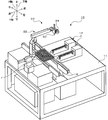
- FIG. 1 is a block diagram of a work system 10;
- FIG. 2 is an external perspective view of a working robot 20.
- 5 is an external perspective view of an end effector 50 of the work robot 20.
- FIG. FIG. 2 is an explanatory view showing an electrical connection relationship of a control device 100.
- 5 is an external perspective view of a suction unit 60.
- FIG. 5 is an external perspective view of a suction unit 60.
- FIG. 5 is an external perspective view of a clamp unit 70.
- FIG. FIG. 7 is a top view of a clamp unit 70.
- FIG. 7 is a top view of a clamp unit 70.
- FIG. 7 is a front view of a clamp unit 70.
- FIG. 7 is a front view of a clamp unit 70.
- FIG. 7 is a front view of a clamp unit 70.
- FIG. 6 is an external perspective view of a turning unit 90. It is a flow chart which shows an example of bolt alignment processing. It is explanatory drawing which shows the mode of the up-down inversion of a volt
- FIG. 1 is a block diagram of a working system 10.
- FIG. 2 is an external perspective view of the working robot 20.
- FIG. 3 is an external perspective view of the end effector 50 (reversing unit) of the working robot 20.
- FIG. 4 is an explanatory view showing an electrical connection relationship of the control device 100.
- the vertical direction is a direction parallel to the vertical direction
- the front-rear direction and the horizontal direction are directions orthogonal to each other and parallel to the horizontal direction orthogonal to the vertical direction.
- the work system 10 includes a bolt feeder 12, a tray conveyance device 14, a work robot 20, and a control device 100 (see FIG. 4) that controls the entire system.
- the bolt feeder 12 is configured to supply the bolt B with the bolt head facing upward.
- the tray conveying device 14 is configured as a belt conveyor device, and conveys the tray T for mounting the bolt B thereon.
- the work robot 20 picks up the bolt B supplied with the bolt head upward by the bolt feeder 12 and upside down so that the bolt head is downward, and then aligns and mounts the bolt B on the tray T
- the working robot 20 includes a 5-axis vertical articulated robot arm 22, a camera 24 attached to the robot arm 22, and an end effector 50.
- the robot arm 22 includes six links (first to sixth links 31 to 36), and a plurality of joints (first to fifth joints 41 to 45) rotatably and rotatably connecting the links 31 to 36, respectively. It has joint drive motors 41a to 45a (see FIG. 4) for driving the corresponding joints, and encoders (not shown) for detecting the angles of the corresponding joints.
- a first link 31 which is a proximal end link is fixed to the work bench 11 and an end effector 50 is attached to a sixth link 36 which is a distal end link.
- the end effector 50 is configured to be able to perform a pickup operation for picking up the bolt B and a reverse operation for turning the bolt B upside down.
- the end effector 50 includes a base plate 51, a suction unit 60, a clamp unit 70, and a pivoting unit 90, as shown in FIG.
- An attachment portion 52 attached to the tip link (sixth link 36) is fixed to the base plate 51.
- FIG. 5 and 6 are external perspective views of the suction unit 60.
- the adsorption unit 60 is for adsorbing the upper end (bolt head) of the bolt B supplied with the bolt head upward by the bolt feeder 12.
- the suction unit 60 includes a suction cylinder 66 for moving the rod 64 in the vertical direction, a suction portion 62 provided at the lower end of the rod 64 and capable of suctioning the upper end (bolt head) of the bolt B, and And a guide member 68 for guiding the stroke.
- the rod 64 is formed in a substantially inverted U shape in the present embodiment.
- a piston is provided at one end of the inverted U-shaped ends of the rod 64, and the piston is accommodated in the suction cylinder 66.
- a suction part 62 is provided at the other end of the inverted U-shaped both ends of the rod 64.
- the suction cylinder 66 is fixed to the base plate 51, and pushes the rod 64 upward to raise the suction portion 62 (see FIG. 5) and pulls the rod 64 downward to lower the suction portion 62. (See Figure 6).
- a pneumatic cylinder can be used as the suction cylinder 66.
- the suction unit 62 is configured to suction the bolt B by negative pressure.
- the adsorbing portion 62 may be configured to adsorb the bolt B by an electromagnet.
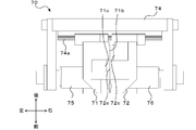
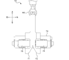
- FIG. 7 is an external perspective view of the clamp unit 70. As shown in FIG. 8 and 9 are top views of the clamp unit 70. FIG. 10 and 11 are front views of the clamp unit 70. FIG. In FIG. 7, the open / close claw 72 and the spring 76 are not shown. The clamp unit 70 clamps the shaft portion of the bolt B from both sides.
- the clamp unit 70 includes a pair of opening and closing claws 71 and 72, a support member 74 slidably supporting the pair of opening and closing claws 71 and 72 in the opening and closing directions (directions approaching and separating from each other), and the pair of opening and closing claws A pair of springs 75 and 76 which always biases 71 and 72 in the closing direction, and a claw drive unit 80 which drives the pair of opening and closing claws 71 and 72 in the opening direction against the biasing force of the springs 75 and 76;
- Have. V-shaped clamp grooves 71a and 72a extending in a straight line shape are formed on the opposing surfaces of the pair of opening and closing claws 71 and 72, respectively.
- the pair of opening and closing claws 71 and 72 sandwich the shaft portion of the bolt B with the clamp grooves 71a and 72a (V-shaped grooves) extending in the axial direction by the biasing force of the springs 75 and 76, thereby opening and closing the bolt head pair
- the bolt B is clamped while being exposed from the claws 71 and 72.
- the claw drive unit 80 has a claw drive cylinder 86 for causing the linear rod 84 to vertically stroke, and a cam 82 provided at the lower end of the rod 84.
- the pawl driving cylinder 86 is fixed to the base plate 51, and pushes the rod 84 downward to lower the cam 82, and retracts the rod 84 to raise the cam 82.
- a pneumatic cylinder can be used as the claw drive cylinder 86.
- the claw drive unit 80 lowers the cam 82 between the pair of opening and closing claws 71 and 72, and spreads the pair of opening and closing claws 71 and 72 by pushing the pair of opening and closing claws 71 and 72 laterally by the cam 82 (See FIG. 9 and FIG. 11).
- the claw drive unit 80 lifts the cam 82 and pulls out the cam 82 from between the pair of opening and closing claws 71 and 72 to close the pair of opening and closing claws 71 and 72 by the biasing force of the pair of springs 75 and 76.
- the cam 82 is in a direction orthogonal to the extending direction of the clamp grooves 71a and 72a and the opening / closing (slide) direction of the pair of open / close claws 71 and 72 (front and rear direction in FIG. 9). And coaxially arranged, and are composed of two independently rotatable cams 82a and 82b.
- the opening and closing claw 71 on the left has an abutting surface 71b with which the outer peripheral surface of the cam 82a abuts, and a relief portion 71c recessed so that the outer peripheral surface of the cam 82b does not abut Is provided.
- the opening and closing claw 72 on the right is recessed so that the contact surface 72b with which the outer peripheral surface of the cam 82b contacts and the outer peripheral surface of the cam 82a do not contact A relief portion 72c is provided.
- the contact surfaces 71 b and 72 b are formed by curved surfaces which are curved to be separated from each other as they go outward from the central portion.
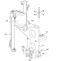
- FIG. 12 is an external perspective view of the turning unit 90. As shown in FIG. In FIG. 12, the illustration of the clamp unit 70 is omitted.
- the pivoting unit 90 pivots the pair of open / close claws 71, 72 180 degrees around an axis orthogonal to the extending direction of the clamp grooves 71a, 72a and the open / close (slide) direction of the pair of open / close claws 71, 72. .
- the pivoting unit 90 is fixed to the base plate 51 and includes a pivoting cylinder 96 that rotates the rotation shaft 94 by 180 degrees.
- a pneumatic cylinder can be used as the turning cylinder 96.
- the support member 74 of the clamp unit 70 is fixed to the rotating shaft 94.
- the turning unit 90 can turn the pair of open / close claws 71 and 72 together with the support member 74 by rotating the rotation shaft 94 by means of the turning cylinder 96.
- the claw drive unit 80 (claw drive cylinder 86) is fixed to the base plate 51 and is separated from the pair of opening and closing claws 71 and 72, it is not turned by the turning unit 90. Therefore, the piping of the claw drive cylinder 86 can be easily managed.
- the control device 100 is configured as a microprocessor centering on the CPU 101, and includes the ROM 102, the HDD 103, and the RAM 104 in addition to the CPU 101.
- An imaging signal from the camera 24, an operation signal from the input device 105 operated by the operator, and the like are input to the control device 100.
- the control device 100 outputs control signals to the bolt feeder 12 and tray conveying device 14, joint drive motors 41a to 45a, camera 24, suction cylinder 66, claw drive cylinder 86, swing cylinder 96, and the like. Be done.
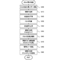
- FIG. 13 is a flowchart showing an example of the bolt alignment process. This process is executed when an instruction to start work is issued by the operation of the input device 105 by the operator. The bolt alignment process will be described below with reference to FIGS. 14 to 20.
- the CPU 101 of the control device 100 first drives and controls the joint driving motors 41a to 45a to attract the bolt B supplied with the bolt head facing upward by the bolt feeder 12 (see FIG. The end effector 50 is moved above the bolt head) (S100). Subsequently, the CPU 101 controls the claw drive unit 80 (claw drive cylinder 86) so that the cams 82a and 82b are pressed against the contact surfaces 71b and 72b between the pair of open / close claws 71 and 72. 82b is lowered, and the pair of open / close claws 71, 72 are spread by the cams 82a, 82b to be in an open state (S110). Then, as shown in FIG.
- the CPU 101 lowers the suction portion 62 so as to pass between the pair of open / close claws 71 and 72 which are opened by controlling the suction cylinder 66 (S 120).
- the bolt head is adsorbed to the adsorbing portion 62 (S130).
- the suction cylinder 66 is controlled to cause the suction portion 62 to slip out between the pair of opening and closing claws 71 and 72 and to cause the bolt B to be between the pair of opening and closing claws 71 and 72
- the suction unit 62 is raised so as to hold the shaft portion of (S140).
- the CPU 101 controls the claw drive cylinder 86 to raise the cams 82a and 82b so that the cams 82a and 82b are pulled out from the contact surfaces 71b and 72b of the pair of open / close claws 71 and 72 (S150).
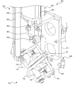
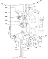
- the pair of open / close claws 71 and 72 are driven in the closing direction by the biasing force of the springs 75 and 76, and clamp the bolt B by sandwiching the shaft portion of the bolt B from both sides. Then, the CPU 101 causes the suction unit 62 to release the suction of the bolt B, and delivers the bolt B to the clamp unit 70 (S160). Next, as shown in FIG. 16 to FIG. 19, the CPU 101 turns the pair of open / close claws 71 and 72 which clamp the bolt B by controlling the turning cylinder 96 by 180 degrees so that the bolt head is upward The bolt B is turned upside down so that the bolt head is in the downward state (S170).
- the CPU 101 controls the joint driving motors 41a to 45a to move the bolt B to the mounting position of the tray T (S180). Then, as shown in FIG. 20, the CPU 101 controls the claw drive cylinder 86 to open the pair of open / close claws 71 and 72, and causes the pair of open / close claws 71 and 72 to release the clamp of the bolt B S190), end the bolt alignment process.
- the end effector 50 of the embodiment corresponds to the component reversing device of the present disclosure
- the bolt B corresponds to the component
- the clamp unit 70 corresponds to the clamp device
- the turning unit 90 corresponds to the turning device.
- the pair of opening and closing claws 71 and 72 correspond to a pair of opening and closing claws
- the claw driving unit 80 corresponds to a claw driving device.
- the cam 82 corresponds to the insertion piece
- the claw drive cylinder 86 corresponds to the moving device.
- the suction unit 62 and the rod 64 correspond to the suction unit
- the suction cylinder 66 corresponds to the lifting device.
- the component reversing device (end effector 40) according to the embodiment described above has a clamp unit 70 that clamps the shaft portion of the component (bolt B) and a pivot that pivots the clamp unit 70 (pair of opening and closing claws 71 and 72) by 180 degrees. And a unit 90.
- the turning unit 90 turns the clamp unit 70 180 degrees in a state where the shaft of the part is clamped by the clamp unit 70, thereby vertically inverting the direction of the shaft of the part.
- the component reversing device can properly reverse the orientation of the shaft of the component without dropping the component.
- the clamp unit 70 is always urged in the closing direction by the urging force, clamps the shaft portion of the component by sandwiching it from both sides, and rotates the rotating unit 90 by 180 degrees by a pair of open / close claws 71 and 72 And a claw drive unit 80 which drives the pair of opening and closing claws 71 and 72 in the opening direction.
- the claw drive unit 80 can be separated from the turning portion such as the pair of opening / closing claws 71 and 72 which is turned by the turning unit 90. Therefore, the wiring of the nail
- a suction unit 62 formed at the tip end as a shaft-like member capable of suctioning a component and arranged so that the axial direction is in the vertical direction, and raising and lowering the suction unit 62 in the vertical direction
- a device suction cylinder 66.
- the component reversing device opens and closes the pair of opening and closing claws 71 and 72 by application of an external force, and moves between the pair of opening and closing claws 71 and 72 in a state where the pair of opening and closing claws 71 and 72 are opened
- the suction unit 62 is lowered to cause the suction unit 62 to suction a component.
- the component reversing device is moved up and down so that the suction portion 62 gets out of the space between the pair of opening and closing claws 71 and 72 and the shaft portion of the component sucked by the suction portion 62 is held between the pair of opening and closing claws 71 and 72
- the suction unit 62 is raised by (the suction cylinder 66).
- the component reversing device releases the application of the external force and clamps the shaft portion of the component by the pair of open / close claws 71 and 72 to deliver the component attracted by the suction unit 62 to the clamp unit 70.
- the arrangement of the piping and wiring of the turning unit 90 can be made easier than in the case where the turning unit 90 is moved up and down directly.
- the rod 64 of the suction unit 60 is formed in an inverted U shape.
- the rod of the adsorption unit may be formed in a straight line.
- the component reversing device includes the suction unit 60, the clamp unit 70, and the swing unit 90.
- the adsorption unit 60 may be omitted.
- the working robot 20 moves the robot arm 22 so that the shaft portion of the bolt B comes between the pair of opening and closing claws 71 and 72 of the clamp unit 70, and then the pair of opening and closing claws 71 is , 72 may be closed.
- the component reversing device is provided with a cylinder (suction cylinder 66, claw drive cylinder 86) as a drive unit of the suction unit 60 (suction unit 62) and the clamp unit 70 (cam 82).
- the component reversing device may be provided with a linear motor, a rotary motor, and a rack and pinion mechanism as its drive unit.
- the component reversing device is provided with a cylinder (turning cylinder 96) as a drive unit of the turning unit 90.
- the component reversing device may be provided with a rotary motor as its drive unit.
- the component reversing device functions as an end effector 50 attached to the tip of the robot arm 22.
- the component reversing device may function as a single device.
- the present disclosure is applicable to, for example, the manufacturing industry of component reversing devices.
Landscapes
- Engineering & Computer Science (AREA)
- Robotics (AREA)
- Mechanical Engineering (AREA)
- Manipulator (AREA)
Abstract
部品反転装置(50)は、軸部を有する部品(B)を反転させるものとして構成され、部品(B)の軸部をクランプするクランプ装置(70)と、クランプ装置(70)を180度旋回する旋回装置(90)と、を備える。部品反転装置(50)は、クランプ装置(70)により部品(B)の軸部をクランプした状態で旋回装置(90)によりクランプ装置(70)を180度旋回することで、部品(B)の軸部の向きを上下反転させる。
Description
本明細書は、部品反転装置について開示する。
従来、この種の部品反転装置としては、部品供給装置から半導体チップ(部品)を取り出すピックアップノズルと、ピックアップノズルを180度回転駆動するθ駆動源と、ピックアップノズルを水平方向に駆動する水平可動体と、を備えるものが提案されている(特許文献1参照)。この部品反転装置は、ピックアップノズルによって半導体チップが取り出されると、θ駆動源によりピックアップノズルを回転駆動することにより、半導体チップを上下方向に180度反転させて実装ツールに受け渡す。実装ツールは、半導体チップがピックアップノズルから受け渡されると、その半導体チップを基板に実装する。
特許文献1記載の部品反転装置は、ノズルに部品を吸着させた状態で当該ノズルを180度旋回することにより部品を上下方向に180度反転させるものであり、チップ部品のような偏平な部品の反転に適している。しかしながら、例えばボルトのような軸部を有する部品の軸部の向きを上下反転させる場合、特許文献1記載の部品反転装置では、ノズルに部品を吸着させたまま部品が落下しないように当該ノズルを回転させるのは困難である。
本開示は、軸部を有する部品の軸部の向きを適切に上下反転させることが可能な部品反転装置を提供することを主目的とする。
本開示は、上述の主目的を達成するために以下の手段を採った。
本開示は、軸部を有する部品を反転させる部品反転装置であって、前記部品の軸部をクランプするクランプ装置と、前記クランプ装置を180度旋回する旋回装置と、を備え、前記クランプ装置により前記部品の軸部をクランプした状態で前記旋回装置により前記クランプ装置を180度旋回することで、前記部品の軸部の向きを上下反転させることを要旨とする。
この本開示の部品反転装置では、クランプ装置により部品の軸部をクランプした状態で、旋回装置によりクランプ装置を180度旋回することで、部品の軸部の向きを上下反転させる。これにより、部品反転装置は、部品を落下させることなく、部品の軸部の向きを適切に上下反転させることができる。ここで、「軸部を有する部品」には、ボルトが含まれる。
次に、本開示を実施するための形態について図面を参照しながら説明する。
図1は、作業システム10の構成図である。図2は、作業ロボット20の外観斜視図である。図3は、作業ロボット20のエンドエフェクタ50(反転ユニット)の外観斜視図である。図4は、制御装置100の電気的な接続関係を示す説明図である。なお、図中、上下方向は、鉛直方向と平行な方向であり、前後方向および左右方向は、互いに直交し、かつ、鉛直方向と直交する水平方向と平行な方向である。
作業システム10は、図1に示すように、ボルトフィーダ12と、トレイ搬送装置14と、作業ロボット20と、システム全体を制御する制御装置100(図4参照)と、を備える。ボルトフィーダ12は、ボルト頭部を上向きにしてボルトBを供給するよう構成されている。トレイ搬送装置14は、ベルトコンベア装置として構成され、ボルトBを載置するためのトレイTを搬送する。
作業ロボット20は、ボルトフィーダ12によりボルト頭部を上向きにして供給されたボルトBをピックアップし、ボルト頭部が下向きになるよう上下反転させてからボルトBをトレイT上に整列して載置するものである。この作業ロボット20は、図2に示すように、5軸の垂直多関節型のロボットアーム22と、ロボットアーム22に取り付けられたカメラ24と、エンドエフェクタ50と、を備える。ロボットアーム22は、6つのリンク(第1~第6リンク31~36)と、各リンク31~36を回転または旋回可能に連結する複数の関節(第1~第5関節41~45)と、対応する関節をそれぞれ駆動する関節駆動用モータ41a~45a(図4参照)と、対応する関節の角度をそれぞれ検出するエンコーダ(図示せず)と、を有する。6つのリンクのうち基端リンクである第1リンク31は、作業台11に固定され、先端リンクである第6リンク36には、エンドエフェクタ50が取り付けられる。
エンドエフェクタ50は、ボルトBをピックアップするピックアップ動作と、ボルトBを上下反転させる反転動作とを実行可能に構成される。このエンドエフェクタ50は、図3に示すように、ベースプレート51と、吸着ユニット60と、クランプユニット70と、旋回ユニット90と、を備える。ベースプレート51には、先端リンク(第6リンク36)に取り付けられる取付部52が固定されている。
図5および図6は、吸着ユニット60の外観斜視図である。吸着ユニット60は、ボルトフィーダ12によりボルト頭部が上向きの状態で供給されたボルトBの上端(ボルト頭部)を吸着するものである。この吸着ユニット60は、ロッド64を上下方向にストロークさせる吸着用シリンダ66と、ロッド64の下端部に設けられてボルトBの上端(ボルト頭部)を吸着可能な吸着部62と、ロッド64のストロークをガイドするガイド部材68と、を有する。ロッド64は、本実施形態では、略逆U字状に形成されている。ロッド64の逆U字の両端部のうち一方の端部には、ピストンが設けられ、当該ピストンは、吸着用シリンダ66に収容される。また、ロッド64の逆U字の両端部のうち他方の端部には、吸着部62が設けられる。これにより、吸着ユニット60は、直線状のロッドを用いる場合に比して、比較的長いストロークを確保しつつ、上下方向の全長をより短縮することができる。吸着用シリンダ66は、ベースプレート51に固定されており、ロッド64を上方へ押し出すことにより、吸着部62を上昇させ(図5参照)、ロッド64を下方へ引き込むことにより、吸着部62を下降させる(図6参照)。吸着用シリンダ66は、例えば、空気圧シリンダを用いることができる。吸着部62は、実施形態では、負圧によってボルトBを吸着するよう構成される。勿論、吸着部62は、電磁石によってボルトBを吸着するよう構成されてもよい。
図7は、クランプユニット70の外観斜視図である。図8および図9は、クランプユニット70の上面図である。図10および図11は、クランプユニット70の正面図である。なお、図7においては、開閉爪72,スプリング76の図示を省略した。クランプユニット70は、ボルトBの軸部を両側から挟んでクランプするものである。このクランプユニット70は、一対の開閉爪71,72と、一対の開閉爪71,72を開閉方向(互いに近接する方向と離間する方向)へスライド自在に支持する支持部材74と、一対の開閉爪71,72を閉方向に常時付勢する一対のスプリング75,76と、スプリング75,76の付勢力に抗して一対の開閉爪71,72を開方向に駆動する爪駆動部80と、を有する。一対の開閉爪71,72の対向面には、それぞれ直線状に延びるV字状のクランプ溝71a,72aが形成されている。一対の開閉爪71,72は、スプリング75,76の付勢力によってボルトBの軸部をその軸方向に延びるクランプ溝71a,72a(V字溝)で挟むことにより、ボルト頭部を一対の開閉爪71,72から露出させつつボルトBをクランプする。
爪駆動部80は、図3に示すように、直線状のロッド84を上下方向にストロークさせる爪駆動用シリンダ86と、ロッド84の下端部に設けられたカム82と、を有する。爪駆動用シリンダ86は、ベースプレート51に固定されており、ロッド84を下方へ押し出すことにより、カム82を下降させ、ロッド84を上方へ引き込むことにより、カム82を上昇させる。爪駆動用シリンダ86は、例えば、空気圧シリンダを用いることができる。爪駆動部80は、一対の開閉爪71,72の間にカム82を下降させ、カム82によって一対の開閉爪71,72を左右に押し広げることにより、一対の開閉爪71,72を開状態とする(図9および図11参照)。また、爪駆動部80は、カム82を上昇させて一対の開閉爪71,72の間からカム82を引き抜くことにより、一対のスプリング75,76の付勢力によって一対の開閉爪71,72を閉状態に戻す(図8および図10参照)。カム82は、実施形態では、図9に示すように、クランプ溝71a,72aの延在方向および一対の開閉爪71,72の開閉(スライド)方向に直交する方向(図9中、前後方向)に同軸上に並び、それぞれ独立して回転可能な2つのカム82a,82bにより構成される。一対の開閉爪71,72のうち図中、左側の開閉爪71には、カム82aの外周面が当接する当接面71bと、カム82bの外周面が当接しないよう窪んだ逃がし部71cとが設けられている。また、同様に、一対の開閉爪71,72のうち図中、右側の開閉爪72には、カム82bの外周面が当接する当接面72bと、カム82aの外周面が当接しないよう窪んだ逃がし部72cとが設けられている。当接面71b,72bは、中央部から外側に向かうにつれて互いに離間するように湾曲した曲面により形成されている。これにより、カム82a,82bを一対の開閉爪71,72の当接面71b,72bに押し当てて一対の開閉爪71,72を開く際に、カム82a,82bの外周面や当接面71b,72bの摩耗が防止される。
図12は、旋回ユニット90の外観斜視図である。なお、図12においては、クランプユニット70の図示を省略した。旋回ユニット90は、一対の開閉爪71,72を、クランプ溝71a,72aの延出方向および一対の開閉爪71,72の開閉(スライド)方向に直交する軸周りに180度旋回させるものである。この旋回ユニット90は、ベースプレート51に固定され、回転軸94を180度回転させる旋回用シリンダ96を備える。旋回用シリンダ96は、例えば、空気圧シリンダを用いることができる。回転軸94には、クランプユニット70の支持部材74が固定される。上述したように、一対の開閉爪71,72は、支持部材74に支持されている。したがって、旋回ユニット90は、旋回用シリンダ96により回転軸94を回転させることにより、支持部材74と共に一対の開閉爪71,72を旋回させることができる。このとき、爪駆動部80(爪駆動用シリンダ86)は、ベースプレート51に固定されており、一対の開閉爪71,72とは分離しているから、旋回ユニット90によって旋回されない。したがって、爪駆動用シリンダ86の配管の取り回しを容易にすることができる。
制御装置100は、図4に示すように、CPU101を中心としたマイクロプロセッサとして構成されており、CPU101の他に、ROM102やHDD103、RAM104を備える。この制御装置100には、カメラ24からの撮像信号、オペレータにより操作される入力装置105からの操作信号などが入力される。また、制御装置100からは、ボルトフィーダ12やトレイ搬送装置14、関節駆動用モータ41a~45a、カメラ24、吸着用シリンダ66、爪駆動用シリンダ86、旋回用シリンダ96などへの制御信号が出力される。
次に、こうして構成された作業システム10の動作について説明する。図13は、ボルト整列処理の一例を示すフローチャートである。この処理は、オペレータの入力装置105の操作により作業開始の指示がなされたときに実行される。以下、ボルト整列処理を、図14~図20を参照しながら説明する。
ボルト整列処理が実行されると、制御装置100のCPU101は、まず、関節駆動用モータ41a~45aを駆動制御してボルトフィーダ12によりボルト頭部を上向きにして供給されたボルトBの吸着位置(ボルト頭部)の上方へエンドエフェクタ50を移動させる(S100)。続いて、CPU101は、爪駆動部80(爪駆動用シリンダ86)を制御して一対の開閉爪71,72の間の当接面71b,72bにカム82a,82bが押し当てられるようカム82a,82bを下降させ、カム82a,82bによって一対の開閉爪71,72を押し広げて開状態とする(S110)。そして、CPU101は、図14に示すように、吸着用シリンダ66を制御して開状態とした一対の開閉爪71,72の間を通過するよう吸着部62を下降させ(S120)、ボルトBのボルト頭部を吸着部62に吸着させる(S130)。
CPU101は、吸着部62にボルトBを吸着させると、吸着用シリンダ66を制御して吸着部62が一対の開閉爪71,72の間を抜け出ると共に一対の開閉爪71,72の間にボルトBの軸部が保持されるよう吸着部62を上昇させる(S140)。続いて、CPU101は、爪駆動用シリンダ86を制御してカム82a,82bが一対の開閉爪71,72の当接面71b,72bから引き抜かれるようカム82a,82bを上昇させる(S150)。これにより、図15に示すように、一対の開閉爪71,72は、スプリング75,76の付勢力によって閉方向に駆動され、ボルトBの軸部を両側から挟んで当該ボルトBをクランプする。そして、CPU101は、吸着部62にボルトBの吸着を解除させて、ボルトBをクランプユニット70へ受け渡す(S160)。次に、CPU101は、図16~図19に示すように、旋回用シリンダ96を制御してボルトBをクランプした一対の開閉爪71,72を180度旋回させ、ボルト頭部が上向きの状態からボルト頭部が下向きの状態となるようボルトBを上下反転させる(S170)。
CPU101は、こうしてボルトBを上下反転させてボルト頭部を下向きにすると、関節駆動用モータ41a~45aを制御してボルトBをトレイTの載置位置へ移動させる(S180)。そして、CPU101は、図20に示すように、爪駆動用シリンダ86を制御して一対の開閉爪71,72を開状態とし、一対の開閉爪71,72にボルトBのクランプを解除させて(S190)、ボルト整列処理を終了する。
ここで、実施形態の主要な要素と請求の範囲に記載した本開示の主要な要素との対応関係について説明する。即ち、実施形態のエンドエフェクタ50が本開示の部品反転装置に相当し、ボルトBが部品に相当し、クランプユニット70がクランプ装置に相当し、旋回ユニット90が旋回装置に相当する。また、一対の開閉爪71,72が一対の開閉爪に相当し、爪駆動部80が爪駆動装置に相当する。また、カム82が挿入片に相当し、爪駆動用シリンダ86が移動装置に相当する。また、吸着部62およびロッド64が吸着部に相当し、吸着用シリンダ66が昇降装置に相当する。
以上説明した実施形態の部品反転装置(エンドエフェクタ40)は、部品(ボルトB)の軸部をクランプするクランプユニット70と、クランプユニット70(一対の開閉爪71,72)を180度旋回する旋回ユニット90と、を備える。旋回ユニット90は、クランプユニット70により部品の軸部をクランプした状態でクランプユニット70を180度旋回することで、部品の軸部の向きを上下反転させる。これにより、部品反転装置は、部品を落下させることなく、部品の軸部の向きを適切に上下反転させることができる。
また、クランプユニット70は、付勢力により閉方向に常時付勢されて部品の軸部を両側から挟んでクランプすると共に旋回ユニット90により180度旋回させられる一対の開閉爪71,72と、外力により一対の開閉爪71,72を開方向に駆動する爪駆動部80と、を有する。これにより、旋回ユニット90により旋回させられる一対の開閉爪71,72などの旋回部から爪駆動部80を分離させることができる。したがって、爪駆動部80の配線や配管の取り回しをより容易にすることができる。
この場合、爪駆動部80は、一対の開閉爪71,72間に挿入されて当該一対の開閉爪71,72間を開方向に押し広げる挿入片(カム82)と、挿入片(カム82)を移動させる移動装置(爪駆動用シリンダ86)と、を有する。これにより、簡易な構成により、爪駆動部80を旋回部から分離させつつ爪駆動部80で一対の開閉爪71,72を開閉させることができる。
また、実施形態の部品反転装置は、先端部に部品を吸着可能な軸状部材として形成され軸方向が上下方向となるよう配置された吸着部62と、吸着部62を上下方向に昇降させる昇降装置(吸着用シリンダ66)と、を含む吸着ユニット60を備える。部品反転装置は、外力の付与により一対の開閉爪71,72を開き、一対の開閉爪71,72を開いた状態で一対の開閉爪71,72間を通るよう昇降装置(吸着用シリンダ66)により吸着部62を下降させて吸着部62に部品を吸着させる。次に、部品反転装置は、吸着部62が一対の開閉爪71,72間から抜け出ると共に吸着部62に吸着された部品の軸部が一対の開閉爪71,72間で保持されるよう昇降装置(吸着用シリンダ66)により吸着部62を上昇させる。そして、部品反転装置は、外力の付与を解除して一対の開閉爪71,72に部品の軸部をクランプさせることにより吸着部62に吸着させた部品をクランプユニット70に受け渡す。これにより、旋回ユニット90を直接に昇降させるものに比して、旋回ユニット90の配管や配線の取り回しを容易にすることができる。
なお、本開示は上述した実施形態に何ら限定されることはなく、本開示の技術的範囲に属する限り種々の態様で実施し得ることはいうまでもない。
例えば、上述した実施形態では、吸着ユニット60のロッド64は、逆U字状に形成されるものとした。しかし、吸着ユニットのロッドは、直線状に形成されてもよい。
上述した実施形態では、部品反転装置は、吸着ユニット60とクランプユニット70と旋回ユニット90とを備えるものとした。しかし、吸着ユニット60は、省略されてもよい。この場合、作業ロボット20は、クランプユニット70の一対の開閉爪71,72の間にボルトBの軸部が来るようにロボットアーム22を移動させた後、爪駆動部80により一対の開閉爪71,72を閉状態とすればよい。
上述した実施形態では、部品反転装置は、吸着ユニット60(吸着部62)やクランプユニット70(カム82)の駆動部としてシリンダ(吸着用シリンダ66,爪駆動用シリンダ86)を備えるものとした。しかし、部品反転装置は、その駆動部として、リニアモータや、回転モータおよびラックピニオン機構を備えるものとしてもよい。
上述した実施形態では、部品反転装置は、旋回ユニット90の駆動部としてシリンダ(旋回用シリンダ96)を備えるものとした。しかし、部品反転装置は、その駆動部として、回転モータを備えるものとしてもよい。
上述した実施形態では、部品反転装置は、ロボットアーム22の先端部に取り付けられるエンドエフェクタ50として機能するものとした。しかし、部品反転装置は、装置単体で機能するものであってもよい。
上述した実施形態では、部品反転装置は、ボルトBの軸部を上下反転させるものに適用されたが、軸部を有する部品であれば、如何なる部品の上下反転にも適用可能である。
本開示は、部品反転装置の製造産業などに利用可能である。
10 作業システム、11 作業台、12 ボルトフィーダ、14 トレイ搬送装置、20 作業ロボット、22 ロボットアーム、24 カメラ、31~36 第1~第6リンク、41~45 第1~第5関節、41a~45b 第1~第5関節駆動用モータ、50 エンドエフェクタ(部品反転装置)、51 ベースプレート、52 取付部、60 吸着ユニット、62 吸着部、64 ロッド、66 吸着用シリンダ、68 ガイド部材、70 クランプユニット、71,72 開閉爪、71a,72a クランプ溝、71b,72b 当接面、71c,72c 逃がし部、74 支持部材、75,76 スプリング、80 爪駆動部、82,82a,82b カム、84 ロッド、86 爪駆動用シリンダ、90 旋回ユニット、94 回転軸、96 旋回用シリンダ、100 制御装置、101 CPU、102 ROM、103 HDD、104 RAM、105 入力装置、T トレイ、B ボルト。
Claims (5)
- 軸部を有する部品を反転させる部品反転装置であって、
前記部品の軸部をクランプするクランプ装置と、
前記クランプ装置を180度旋回する旋回装置と、
を備え、
前記クランプ装置により前記部品の軸部をクランプした状態で前記旋回装置により前記クランプ装置を180度旋回することで、前記部品の軸部の向きを上下反転させる、
部品反転装置。 - 請求項1に記載の部品反転装置であって、
前記クランプ装置は、付勢力により閉方向に常時付勢されて前記部品の軸部を両側から挟んでクランプすると共に前記旋回装置により180度旋回させられる一対の開閉爪と、外力により前記一対の開閉爪を開方向に駆動する爪駆動装置と、を有する、
部品反転装置。 - 請求項2に記載の部品反転装置であって、
前記爪駆動装置は、前記一対の開閉爪間に挿入されて該一対の開閉爪間を開方向に押し広げる挿入片と、該挿入片を移動させる移動装置と、を有する、
部品反転装置。 - 請求項2または3に記載の部品反転装置であって、
先端部に前記部品を吸着可能な軸状部材として形成され軸方向が上下方向となるよう配置された吸着部と、前記吸着部を上下方向に昇降させる昇降装置と、を有し、
外力の付与により前記一対の開閉爪を開き、前記一対の開閉爪を開いた状態で該一対の開閉爪間を通るよう前記昇降装置により前記吸着部を下降させて該吸着部に前記部品を吸着させ、前記吸着部が前記一対の開閉爪間から抜け出ると共に前記吸着部に吸着された部品の軸部が前記一対の開閉爪間で保持されるよう前記昇降装置により該吸着部を上昇させ、外力の付与を解除して前記一対の開閉爪に前記軸部をクランプさせることにより前記吸着部に吸着させた部品を前記クランプ装置に受け渡す、
部品反転装置。 - 請求項1ないし4いずれか1項に記載の部品反転装置であって、
前記部品は、ボルトである、
部品反転装置。
Priority Applications (2)
| Application Number | Priority Date | Filing Date | Title |
|---|---|---|---|
| PCT/JP2017/025283 WO2019012604A1 (ja) | 2017-07-11 | 2017-07-11 | 部品反転装置 |
| JP2019529357A JP6789394B2 (ja) | 2017-07-11 | 2017-07-11 | 部品反転装置 |
Applications Claiming Priority (1)
| Application Number | Priority Date | Filing Date | Title |
|---|---|---|---|
| PCT/JP2017/025283 WO2019012604A1 (ja) | 2017-07-11 | 2017-07-11 | 部品反転装置 |
Publications (1)
| Publication Number | Publication Date |
|---|---|
| WO2019012604A1 true WO2019012604A1 (ja) | 2019-01-17 |
Family
ID=65001567
Family Applications (1)
| Application Number | Title | Priority Date | Filing Date |
|---|---|---|---|
| PCT/JP2017/025283 Ceased WO2019012604A1 (ja) | 2017-07-11 | 2017-07-11 | 部品反転装置 |
Country Status (2)
| Country | Link |
|---|---|
| JP (1) | JP6789394B2 (ja) |
| WO (1) | WO2019012604A1 (ja) |
Cited By (3)
| Publication number | Priority date | Publication date | Assignee | Title |
|---|---|---|---|---|
| CN112171703A (zh) * | 2020-11-03 | 2021-01-05 | 北华航天工业学院 | 一种可定位和翻转的吸盘式末端执行器 |
| CN114212534A (zh) * | 2021-11-30 | 2022-03-22 | 张大为 | 一种智能制造用垂直抓取提升装置 |
| CN115656203A (zh) * | 2022-09-27 | 2023-01-31 | 广州超音速自动化科技股份有限公司 | 一种膜电极ccd检测设备 |
Citations (9)
| Publication number | Priority date | Publication date | Assignee | Title |
|---|---|---|---|---|
| JPS52111169A (en) * | 1976-03-12 | 1977-09-17 | Sankyo Seiki Seisakusho Kk | Bolttlike parts feeder |
| JPS61273418A (ja) * | 1985-05-28 | 1986-12-03 | Pioneer Electronic Corp | ワ−ク反転装置 |
| JPH11129182A (ja) * | 1997-10-28 | 1999-05-18 | Asahi Seiki Mfg Co Ltd | ワーク反転方法並びに装置 |
| US5947539A (en) * | 1997-05-30 | 1999-09-07 | Eastman Kodak Company | Apparatus and method having short linear motion for grasping objects |
| JP2004237412A (ja) * | 2003-02-07 | 2004-08-26 | Nke Corp | ピックアンドプレース装置 |
| WO2012029834A1 (ja) * | 2010-09-03 | 2012-03-08 | 株式会社日立ハイテクノロジーズ | 検体移載機構 |
| JP2012066357A (ja) * | 2010-09-24 | 2012-04-05 | Yaskawa Electric Corp | ハンド及びロボット |
| JP2015077653A (ja) * | 2013-10-17 | 2015-04-23 | 三菱電機株式会社 | 把持装置 |
| JP2017109271A (ja) * | 2015-12-17 | 2017-06-22 | パナソニックIpマネジメント株式会社 | 作業装置および作業方法 |
-
2017
- 2017-07-11 WO PCT/JP2017/025283 patent/WO2019012604A1/ja not_active Ceased
- 2017-07-11 JP JP2019529357A patent/JP6789394B2/ja active Active
Patent Citations (9)
| Publication number | Priority date | Publication date | Assignee | Title |
|---|---|---|---|---|
| JPS52111169A (en) * | 1976-03-12 | 1977-09-17 | Sankyo Seiki Seisakusho Kk | Bolttlike parts feeder |
| JPS61273418A (ja) * | 1985-05-28 | 1986-12-03 | Pioneer Electronic Corp | ワ−ク反転装置 |
| US5947539A (en) * | 1997-05-30 | 1999-09-07 | Eastman Kodak Company | Apparatus and method having short linear motion for grasping objects |
| JPH11129182A (ja) * | 1997-10-28 | 1999-05-18 | Asahi Seiki Mfg Co Ltd | ワーク反転方法並びに装置 |
| JP2004237412A (ja) * | 2003-02-07 | 2004-08-26 | Nke Corp | ピックアンドプレース装置 |
| WO2012029834A1 (ja) * | 2010-09-03 | 2012-03-08 | 株式会社日立ハイテクノロジーズ | 検体移載機構 |
| JP2012066357A (ja) * | 2010-09-24 | 2012-04-05 | Yaskawa Electric Corp | ハンド及びロボット |
| JP2015077653A (ja) * | 2013-10-17 | 2015-04-23 | 三菱電機株式会社 | 把持装置 |
| JP2017109271A (ja) * | 2015-12-17 | 2017-06-22 | パナソニックIpマネジメント株式会社 | 作業装置および作業方法 |
Cited By (3)
| Publication number | Priority date | Publication date | Assignee | Title |
|---|---|---|---|---|
| CN112171703A (zh) * | 2020-11-03 | 2021-01-05 | 北华航天工业学院 | 一种可定位和翻转的吸盘式末端执行器 |
| CN114212534A (zh) * | 2021-11-30 | 2022-03-22 | 张大为 | 一种智能制造用垂直抓取提升装置 |
| CN115656203A (zh) * | 2022-09-27 | 2023-01-31 | 广州超音速自动化科技股份有限公司 | 一种膜电极ccd检测设备 |
Also Published As
| Publication number | Publication date |
|---|---|
| JPWO2019012604A1 (ja) | 2020-01-09 |
| JP6789394B2 (ja) | 2020-11-25 |
Similar Documents
| Publication | Publication Date | Title |
|---|---|---|
| CN108687791B (zh) | 夹具以及机器人系统 | |
| CN104444360B (zh) | 轮毂五轴搬运机器人及夹持机械手 | |
| CN111655436B (zh) | 用于在不同位置之间传送夹紧装置的卡接定位装置 | |
| US20220339801A1 (en) | Gripper jaw, tool, tool system and method for operating a tool system | |
| CN107438357A (zh) | 自动组装装置 | |
| WO2018054383A1 (zh) | 晶圆传输装置 | |
| CN107275268A (zh) | 机械手单元及移载方法 | |
| CN111065497B (zh) | 工件输送机器人 | |
| KR20190016102A (ko) | 로봇, 반송 장치 및 하네스가 구비된 커넥터의 반송 방법 | |
| CN108622655A (zh) | 板握持装置及板握持方法 | |
| WO2007097147A1 (ja) | 搬送装置及び搬送方法 | |
| WO2014147937A1 (ja) | ワーク搬入装置 | |
| CN221271174U (zh) | 抓取装置及机器人 | |
| CN107000203A (zh) | 机械臂 | |
| WO2017213015A1 (ja) | 食品の詰め込み装置 | |
| JP6789394B2 (ja) | 部品反転装置 | |
| US11718937B2 (en) | Adaptive apparatus for transporting and sewing material along arbitrary seam shapes | |
| JP5913845B2 (ja) | 板状部材の搬送装置および搬送方法 | |
| JP6411852B2 (ja) | 搬送装置、搬送システム及び搬送方法 | |
| CN109384045A (zh) | 背板上料机械手夹具装置 | |
| CN111065498B (zh) | 机器人手、机器人装置、以及生产电子设备的方法 | |
| JP5999198B2 (ja) | ロボットシステム | |
| CN113458907A (zh) | 一种芯取全自动上下料机 | |
| JP5152498B2 (ja) | ワークの位置決め装置及び方法並びに突合せ溶接用ワークの位置決め装置 | |
| CN111405967B (zh) | 末端执行器、多关节机器人及作业执行装置 |
Legal Events
| Date | Code | Title | Description |
|---|---|---|---|
| 121 | Ep: the epo has been informed by wipo that ep was designated in this application |
Ref document number: 17917624 Country of ref document: EP Kind code of ref document: A1 |
|
| ENP | Entry into the national phase |
Ref document number: 2019529357 Country of ref document: JP Kind code of ref document: A |
|
| NENP | Non-entry into the national phase |
Ref country code: DE |
|
| 122 | Ep: pct application non-entry in european phase |
Ref document number: 17917624 Country of ref document: EP Kind code of ref document: A1 |