WO2019012602A1 - 内視鏡システム、画像診断システム - Google Patents
内視鏡システム、画像診断システム Download PDFInfo
- Publication number
- WO2019012602A1 WO2019012602A1 PCT/JP2017/025254 JP2017025254W WO2019012602A1 WO 2019012602 A1 WO2019012602 A1 WO 2019012602A1 JP 2017025254 W JP2017025254 W JP 2017025254W WO 2019012602 A1 WO2019012602 A1 WO 2019012602A1
- Authority
- WO
- WIPO (PCT)
- Prior art keywords
- probe
- image
- endoscope
- reference direction
- endoscope system
- Prior art date
- Legal status (The legal status is an assumption and is not a legal conclusion. Google has not performed a legal analysis and makes no representation as to the accuracy of the status listed.)
- Ceased
Links
Images







Classifications
-
- A—HUMAN NECESSITIES
- A61—MEDICAL OR VETERINARY SCIENCE; HYGIENE
- A61B—DIAGNOSIS; SURGERY; IDENTIFICATION
- A61B1/00—Instruments for performing medical examinations of the interior of cavities or tubes of the body by visual or photographical inspection, e.g. endoscopes; Illuminating arrangements therefor
- A61B1/00002—Operational features of endoscopes
- A61B1/00004—Operational features of endoscopes characterised by electronic signal processing
- A61B1/00006—Operational features of endoscopes characterised by electronic signal processing of control signals
-
- A—HUMAN NECESSITIES
- A61—MEDICAL OR VETERINARY SCIENCE; HYGIENE
- A61B—DIAGNOSIS; SURGERY; IDENTIFICATION
- A61B1/00—Instruments for performing medical examinations of the interior of cavities or tubes of the body by visual or photographical inspection, e.g. endoscopes; Illuminating arrangements therefor
- A61B1/00002—Operational features of endoscopes
- A61B1/00043—Operational features of endoscopes provided with output arrangements
- A61B1/00045—Display arrangement
- A61B1/0005—Display arrangement combining images e.g. side-by-side, superimposed or tiled
-
- A—HUMAN NECESSITIES
- A61—MEDICAL OR VETERINARY SCIENCE; HYGIENE
- A61B—DIAGNOSIS; SURGERY; IDENTIFICATION
- A61B1/00—Instruments for performing medical examinations of the interior of cavities or tubes of the body by visual or photographical inspection, e.g. endoscopes; Illuminating arrangements therefor
- A61B1/005—Flexible endoscopes
-
- A—HUMAN NECESSITIES
- A61—MEDICAL OR VETERINARY SCIENCE; HYGIENE
- A61B—DIAGNOSIS; SURGERY; IDENTIFICATION
- A61B1/00—Instruments for performing medical examinations of the interior of cavities or tubes of the body by visual or photographical inspection, e.g. endoscopes; Illuminating arrangements therefor
- A61B1/04—Instruments for performing medical examinations of the interior of cavities or tubes of the body by visual or photographical inspection, e.g. endoscopes; Illuminating arrangements therefor combined with photographic or television appliances
- A61B1/05—Instruments for performing medical examinations of the interior of cavities or tubes of the body by visual or photographical inspection, e.g. endoscopes; Illuminating arrangements therefor combined with photographic or television appliances characterised by the image sensor, e.g. camera, being in the distal end portion
-
- A—HUMAN NECESSITIES
- A61—MEDICAL OR VETERINARY SCIENCE; HYGIENE
- A61B—DIAGNOSIS; SURGERY; IDENTIFICATION
- A61B1/00—Instruments for performing medical examinations of the interior of cavities or tubes of the body by visual or photographical inspection, e.g. endoscopes; Illuminating arrangements therefor
- A61B1/06—Instruments for performing medical examinations of the interior of cavities or tubes of the body by visual or photographical inspection, e.g. endoscopes; Illuminating arrangements therefor with illuminating arrangements
- A61B1/0615—Instruments for performing medical examinations of the interior of cavities or tubes of the body by visual or photographical inspection, e.g. endoscopes; Illuminating arrangements therefor with illuminating arrangements for radial illumination
-
- A—HUMAN NECESSITIES
- A61—MEDICAL OR VETERINARY SCIENCE; HYGIENE
- A61B—DIAGNOSIS; SURGERY; IDENTIFICATION
- A61B5/00—Measuring for diagnostic purposes; Identification of persons
- A61B5/06—Devices, other than using radiation, for detecting or locating foreign bodies ; Determining position of diagnostic devices within or on the body of the patient
- A61B5/061—Determining position of a probe within the body employing means separate from the probe, e.g. sensing internal probe position employing impedance electrodes on the surface of the body
- A61B5/062—Determining position of a probe within the body employing means separate from the probe, e.g. sensing internal probe position employing impedance electrodes on the surface of the body using magnetic field
-
- A—HUMAN NECESSITIES
- A61—MEDICAL OR VETERINARY SCIENCE; HYGIENE
- A61B—DIAGNOSIS; SURGERY; IDENTIFICATION
- A61B34/00—Computer-aided surgery; Manipulators or robots specially adapted for use in surgery
- A61B34/20—Surgical navigation systems; Devices for tracking or guiding surgical instruments, e.g. for frameless stereotaxis
- A61B2034/2046—Tracking techniques
- A61B2034/2051—Electromagnetic tracking systems
-
- A—HUMAN NECESSITIES
- A61—MEDICAL OR VETERINARY SCIENCE; HYGIENE
- A61B—DIAGNOSIS; SURGERY; IDENTIFICATION
- A61B5/00—Measuring for diagnostic purposes; Identification of persons
- A61B5/06—Devices, other than using radiation, for detecting or locating foreign bodies ; Determining position of diagnostic devices within or on the body of the patient
- A61B5/065—Determining position of the probe employing exclusively positioning means located on or in the probe, e.g. using position sensors arranged on the probe
- A61B5/066—Superposing sensor position on an image of the patient, e.g. obtained by ultrasound or x-ray imaging
Definitions
- the present invention relates to an endoscope system for observing the inside of a recipient.
- Patent Document 1 discloses an endoscope apparatus capable of adjusting the bending angle of the insertion portion.
- the endoscope apparatus includes a plurality of acceleration sensors, which can detect the bending state of the insertion portion.
- An endoscope system includes an endoscope having a shaft and a light receiving unit having an optical axis in a direction intersecting the shaft, and an image acquired via the light receiving unit.
- the first probe provided on the endoscope around the optical axis or the optical axis at a position deviated from the axis, the position at which the axis and the optical axis intersect, or In the vicinity thereof, a second probe provided in the endoscope, a sensor for detecting the position of the first probe, and the position of the second probe, and a direction from the second probe to the first probe
- the control part which acquires the direction which goes to a said 2nd probe from a said 1st probe as a direction of the said optical axis.
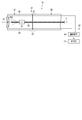
- FIG. 1 is a schematic view showing an entire configuration of an image diagnostic system and an endoscope system according to a first embodiment.
- FIG. 2 is a side view perspectively showing the vicinity of the tip end configuration of the endoscope insertion portion of the endoscope system shown in FIG.
- FIG. 3 is a side view showing a guide pipe and an endoscope main body of the endoscope system shown in FIG.
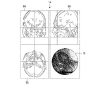
- FIG. 4 is a schematic view showing an image and a cross-sectional image displayed on the display unit shown in FIG.
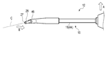
- FIG. 5 is a side view schematically showing the insertion device partially inserted in the hole (nasal cavity) of the examinee.
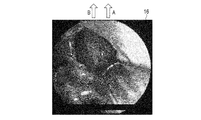
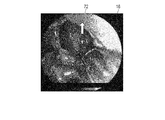
- FIG. 6 is a schematic view showing an image (endoscope image) obtained from the endoscope main body of the insertion device shown in FIG.
- FIG. 7 is a side view schematically showing a state in which the grip portion is rotated approximately 90 degrees in the counterclockwise direction from the state shown in FIG.
- FIG. 8 is a schematic view showing an image (endoscope image) obtained from the endoscope main body of the insertion device shown in FIG.
- FIG. 9 is a schematic view showing a state in which an arrow indicating the second reference direction is shown in the image displayed on the display unit in the calibration step.
- FIG. 10 is a schematic view showing a relationship between the first reference direction and the second reference direction, and schematically showing the concept of making the second reference direction coincide with the first reference direction.
- FIG. 11 is a schematic view showing a state in which the image is rotated 90 ° counterclockwise so that the second reference direction in the image substantially matches the first reference direction in real space.
- FIG. 12 is a schematic view showing the overall configuration of an image diagnostic system and an endoscope system according to a modification of the first embodiment.
- FIG. 13 is a schematic view showing a second reference direction in an image in the image diagnosis system and the endoscope system according to the second embodiment.
- FIG. 14 is a schematic view showing a state in which the image and the second reference direction are rotated approximately 90 ° clockwise while the grip portion is rotated approximately 90 ° counterclockwise from the state shown in FIG. 5 is there.
- FIG. 15 is a schematic view showing an entire configuration of an image diagnostic system and an endoscope system according to a third embodiment.
- the diagnostic imaging system 1 comprises a cross-sectional image acquisition device 5 for acquiring a cross-sectional image of a examinee, and an endoscope system 11 which is inserted into the examinee's body and used for observation in the body.
- the cross-sectional image acquisition device 5 is configured by, for example, a CT (Computed Tomography) device, but is not limited to this.
- the cross-sectional image acquisition device 5 can acquire, for example, a coronal section image 64, an axial section image 65, and a sagittal section image 66.
- the cross-sectional image acquisition device 5 may be, for example, a device capable of acquiring cross-sectional images other than a CT device, such as an MRI (Magnetic Resonance Imaging) device.
- the endoscope system 11 is electrically connected to the insertion device 12 used by being inserted into the nasal cavity and the paranasal sinuses, etc., and power lines for supplying power to the insertion device 12 and various signal lines.
- a control unit 13, a display unit 14 connected to the control unit 13, and a navigation system 8 for detecting the position and orientation of the insertion device 12 are included.
- the navigation system 8 is an example of a sensor.
- the navigation system 8 is configured of, for example, a magnetic sensor that can detect the positions of first to third probes 61 to 63, which will be described later, provided on the endoscope system 11 by magnetism.
- the navigation system 8 may be, for example, an optical sensor capable of detecting the positions of the first to third probes 61 to 63 with infrared light.
- the insertion device 12 is provided separately from the display unit 14 and the control unit 13.
- the display unit 14 is configured by a general liquid crystal monitor, and can display an image acquired by the endoscope 15 as an image 16 (endoscope image).
- the insertion device 12 passes through the grip 17 having an outer shell, the cylindrical guide pipe 18 projecting from the grip 17, the guide pipe 18 and the inside of the grip 17. And an endoscope imaging unit 22 (imaging unit) provided inside the holding unit 17, and a bending drive unit 23 provided in the holding unit 17.
- the gripping portion 17 has, for example, a cylindrical shape, and constitutes a portion (housing) to be gripped by the user's hand.
- the endoscope 15 includes the endoscope main body 21 and the endoscope imaging unit 22.
- the endoscope 15 is configured by an endoscope 15 in which these are integrated. It may be done.
- the axial direction (central axis direction) of the shaft portion 44 of the guide pipe 18 to be described later is L
- the direction from the grip portion 17 to the elbow portion 45 of the axial direction L is L1.
- a description will be given assuming that the direction from the portion 45 toward the gripping portion 17 is L2.
- the endoscope 15 is configured by a so-called scanning endoscope.
- the endoscope 15 (endoscope main body 21) is configured to have flexibility. For this reason, the endoscope main body 21 can be curved following the shape of the guide pipe 18 by being passed through the guide pipe 18.
- the direction of the endoscope main body 21 can be adjusted by the guide pipe 18.
- a central axis C (optical axis C) is defined along the longitudinal direction.
- the optical axis C of the tip end forming portion 27 extends in a direction intersecting the shaft portion 44 of the guide pipe 18. As shown in FIG.
- the endoscope main body 21 may be moved along the central axis C direction to be projected from the projection 46 of the guide pipe 18 or to be housed again in the projection 46. it can.
- the endoscope main body 21 can acquire an image of the optical axis C and the periphery thereof.
- the endoscope main body portion 21 has a distal end constituting portion 27 (light receiving portion) positioned on the distal end side in the central axis C direction and a proximal end side in the central axis C direction than the distal end constituting portion 27 And a wire (pull wire) provided in a pair on the left and right so as to straddle the tip of the sheath 32 and the grip portion 17, a tip configuration 27, a flexible tube 28, and a tubular covering the wire ,
- the illumination window 33, the rotation unit 34, the illumination fiber 35, and the plurality of light reception fibers 36 is a structure that can be curved in the left-right direction (or the up-down direction) as shown in FIG. 1 together with the endoscope main body 21 (flexible tube 28) held inside thereof.
- the gripping portion 17 may be further provided with an advancing and retracting mechanism 25 for advancing and retracting the endoscope main body portion 21 in the axial direction L with respect to the guide pipe 18.
- the advancing and retracting mechanism 25 is constituted by, for example, a knob portion capable of advancing and retracting the support unit 26.
- the endoscope main body 21 is guided by the guide pipe 18 when being advanced and retracted by the advancing and retracting mechanism 25.
- the user uses the advancing / retracting mechanism 25 or the like in a state where the guide pipe 18 is inserted in the sinus (nasal cavity 55, paranasal sinus etc.) of the examinee in the medical examination, and the distal end configuration part of the endoscope main body 21 from the guide pipe 18 27 (the light receiving portion) is protruded from the projecting portion 46, the tip end forming portion 27 is housed again in the projecting portion 46, or the bending angle of the endoscope main body portion 21 is changed using the bending driving portion 23. it can. By these, the desired image in the sinus can be obtained.
- the bending drive portion 23 includes a support unit 26 housed slidably in the axial direction L of the guide pipe 18 inside the grip portion 17, a shaft 37 rotatably supported with respect to the support unit 26, and a shaft 37. And a non-illustrated sprocket fixed to the other end of the shaft 37 inside the case of the support unit 26.
- the shaft 37 protrudes from the long hole 41 formed in the grip 17 to the outside of the grip 17.
- Connected to the end of the wire is a chain which can be engaged with the sprocket.
- One of the pair of wires is pulled along with the rotation of the dial 38, and the other end of the pair of wires is pulled, whereby the tip of the sheath 32 is pulled and the sheath 32 is curved in one of the left and right in FIG. Be done.
- the bending of the sheath 32 bends the endoscope body 21 (flexible tube 28) located inside.
- the bending direction of the sheath 32 is an example, and the sheath 32 may be curved on the back side and the front side of the paper surface in FIG. 1, or the number of wires is four and in four directions of upper, lower, left, and right Naturally it is good even if it can be bent.
- the wire (linear member) can be pulled to adjust the bending angle of the endoscope 15 (endoscope main body 21).
- the illumination fiber 35 is optically connected to a light source provided adjacent to the control unit 13.
- the plurality of light receiving fibers 36 are optically connected to the light detector 42.
- the tip of the light receiving fiber 36 is exposed to the outside in the vicinity of the tip configuration portion 27. Therefore, the endoscope 15 can acquire an image through the light receiving fiber 36 in the distal end forming portion 27.
- the endoscope 15 can acquire an image around the optical axis C shown in FIG. 2 through the light receiving fiber 36.
- the endoscope imaging unit 22 has a general light detector 42.
- the endoscope imaging unit 22 can acquire an image obtained by the distal end forming unit 27 of the endoscope main body unit 21. More specifically, the photodetector 42 converts the light from the light receiving fiber 36 into an electrical signal and sends it to the control unit 13.
- the rotation unit 34 is electrically connected to the control unit 13.
- the rotation unit 34 is configured by a motor or the like, and is swung, for example, in a spiral under the control of the control unit 13 (motor driver 43). Therefore, the tip 35A of the illumination fiber 35 is swung in a spiral according to the operation of the rotation unit 34. Therefore, the surface of the object is scanned in a spiral manner by the illumination light from the illumination fiber 35 through the tip 35 A of the illumination fiber 35 and the illumination window 33.
- the plurality of light receiving fibers 36 receive the return light from the subject and guide the light to the light detector 42.
- the photodetector 42 sends the light received by the plurality of light receiving fibers 36 to the control unit 13 as an electrical signal.
- the control unit 13 images the electric signal, appropriately performs image processing, and displays the image on the display unit 14.
- FIG. 4 shows an image displayed on the display unit 14.
- a coronal section (Coronal section) image 64 obtained from the cross-sectional image acquisition device 5
- a body axial cross-section (Axial section) image 65 obtained from the cross-sectional image acquisition device 5
- the cross-sectional image acquisition device 5 And the image 16 obtained from the endoscope main body 21 is displayed. Therefore, the user can confirm the four images 64 to 66, 16 on one screen displayed on the display unit 14.
- the guide pipe 18 (guide portion) has a substantially “L” shape as a whole, and has a cylindrical (cylindrical) shape which is bent in an elbow shape halfway.
- the guide pipe 18 has a shaft 44 attached to the grip 17 at one end, an elbow 45 provided at the other end of the shaft 44, and a direction in which the shaft 44 extends from the elbow 45 And a protrusion 46 protruding in a cross direction (i.e., side).
- the guide pipe 18 includes a first probe 61 provided near the tip of the protrusion 46, a second probe 62 provided on the elbow 45 (shaft 44), and a second probe 62 provided on the root side of the shaft 44. And 3 probes 63.
- the first probe 61, the second probe 62, and the third probe 63 are each formed of, for example, a small piece of metal, and the position on the three-dimensional space is detected by the navigation system 8 configured by a magnetic sensor.
- the first probe 61 is provided around the optical axis C or the optical axis C at a position deviated from the shaft 44.
- the second probe 62 is provided at or near a position where the shaft 44 and the optical axis C intersect.
- the third probe 63 is provided on the shaft 44 at a position deviated from the position at which the second probe 62 is provided.
- the first probe 61, the second probe 62, and the third probe 63 are each configured by, for example, an infrared reflecting sphere.
- the navigation system 8 detects the positions of the first probe 61, the second probe 62, and the third probe 63 in a three-dimensional space.
- the first probe 61, the second probe 62, and the third probe 63 can be distinguished from one another by the navigation system 8.
- the endoscope main body 21 can be passed through the guide pipe 18 inside.
- the inner wall of the guide pipe 18 can guide the endoscope main body 21 which moves back and forth along the central axis C.
- the guide pipe 18 is preferably fixedly provided, for example, with respect to the gripping portion 17, but may be rotatable around the axial direction L with respect to the gripping portion 17. In that case, the grip 17 may be provided with a rotation knob for rotating the guide pipe 18 in the axial direction L.
- the control unit 13 illustrated in FIG. 1 includes, for example, a control unit main body 47 configured by a general computer, and a power supply 48 provided separately from the control unit main body 47.
- the control unit main body 47 is installed in a housing 51, a circuit board 52 incorporated in the housing 51, a CPU mounted on the circuit board 52, a ROM, a RAM, an HDD 53 (hard disk drive), and an HDD 53
- Third software installed in the HDD 53 and acquiring the positions of the first to third probes 61 to 63 through the navigation system 8, a motor driver 43 built in the housing 51 for controlling the rotation unit 34, It consists of
- the control unit 13 can store the first reference direction and the second reference direction preset by the user as vector amounts and the like.
- the second software includes a coronal section image 64 centered on the position of the first probe 61, an axial section image 65 centered on the position of the first probe 61, and the first probe 61.
- a sagittal section image 66 centered on the position, and an image 16 (endoscopic image) obtained from the endoscope 15 can be displayed side by side on the display unit 14.
- the power supply 48 can supply power to the rotation unit 34.
- the control unit main body 47 can perform, for example, the following control on each unit of the insertion device 12.
- the control unit main body 47 can control the rotation unit 34 via the motor driver 43 to adjust the rotation speed and the like.
- the control unit main body 47 can control the light source to adjust the amount of light supplied to the illumination fiber 35.
- the control unit main body 47 can process and image an electrical signal corresponding to an image acquired by the light detector 42 of the insertion device 12 and can display the image 16 (endoscope image) on the display unit 14.
- the maxillary sinus of the human paranasal sinuses comprises a bifurcation extending laterally from the nasal cavity 55 with respect to the nasal cavity 55 located approximately in the center of the face and extending in the anterior posterior direction.
- a middle nasal turbinate or the like which is an organ separating them, is provided.
- the endoscope main body 21 is rotated about 110 ° laterally from the back of the examinee It is necessary to direct the tip end portion 27 of the endoscope main body 21 and the optical axis C to the right angle.
- FIG. 5 shows a state in which the guide pipe 18 is inserted into the nasal cavity 55 on the right side of the examinee.
- the protrusion 46 of the guide pipe 18 protrudes toward the superior direction of the examinee.
- FIG. 5 when the user lifts the grip 17 toward the top of the head of the examinee (arrow A) on the near side, the image 16 obtained from the endoscope main body 21 is also substantially upward (arrow B). Move towards).
- This state is shown by an image 16 as shown in FIG.
- FIG. 6 the direction in which the user lifts the grip 17 (arrow A) and the direction in which the image 16 scrolls (arrow B) are the same. For this reason, when the endoscope 15 is in such a positional relationship, the user is not confused.
- the control unit 13 obtains the first reference direction 71 determined by the user in the actual space (real space) from the endoscope main body 21.
- a second reference direction 72 is set in the obtained image 16 (endoscope image), and processing for matching the second reference direction 72 with the first reference direction 71 is performed. That is, for example, when the positional relationship as shown in FIG. 5, that is, the positional relationship in which the direction in which the protrusion 46 protrudes (the direction from the second probe 62 toward the first probe 61) is the head direction of the examinee
- the user performs a calibration process, which is a process of setting the first reference direction 71 and the second reference direction 72.
- the first reference direction 71 and the second reference direction 72 can be arbitrarily determined by the user in the calibration screen as shown in FIG.
- the switch 54 or the like provided in the control unit 13 can be used.
- the control unit 13 can set the direction from the second probe 62 to the first probe 61 as the first reference direction 71 set in the real space at a predetermined timing.
- the first reference direction 71 is directed from the second probe 62 to the first probe 61 It becomes a direction, and becomes a superior direction (Superior direction) recognized by the user in real space.
- the method of setting the first reference direction 71 is arbitrary.
- the direction from the first probe 61 to the second probe 62 may be set as the first reference direction 71 set in the real space.
- the first reference direction 71 is set in this manner when the insertion device 12 has the positional relationship as shown in FIG. 5, the first reference direction 71 is a jaw recognized by the user in the real space. It is the inferior direction.
- the user can set a second reference direction 72 corresponding to the first reference direction 71 in the image 16 (endoscopic image).
- the step of setting the second reference direction 72 is preferably simultaneous with the setting of the first reference direction 71 described above.
- the second reference direction 72 is set by the user appropriately selecting any one of two directions in the image 16 parallel to the plane 73 passing through the first probe 61, the second probe 62, and the third probe 63. It can be set. In this case, as shown in FIG. 9, the user can set, for example, the upward direction in the image 16 as the second reference direction 72.
- the arrow indicating the second reference direction 72 of the image 16 may be displayed as it is in the image 16 or the display in the image 16 may be canceled after a predetermined time has elapsed.
- the first reference direction 71 is set to the jaw direction of the examinee, for example, the lower direction in the image 16 can be set as the second reference direction 72.
- control unit 13 sets the first reference direction 71 and the second reference direction 72 in the calibration process from the positions (coordinates) of the first probe 61, the second probe 62, and the third probe 63 in the real space.
- the posture of the insertion device 12 at the time of setting is grasped.
- the control unit 13 performs image processing to rotate, for example, the image 16 clockwise by, for example, 90 ° as illustrated in FIG. Also in this case, the control unit 13 can substantially match the second reference direction 72 in the image 16 with the first reference direction 71 in real space. Further, the angle for rotating the image 16 in the clockwise direction may not be 90 °.
- the control unit 13 can define an X axis, a Y axis, and a Z axis.
- the X axis is defined in a direction parallel to the axial direction L of the shaft portion 44.
- the XY plane corresponds to, for example, a horizontal plane
- the Z axis corresponds to, for example, the vertical direction.
- the control unit 13 is parallel to the XZ plane when the vector of the first reference direction 71 is decomposed into a first component 71A parallel to the XZ plane and a second component 71B (Y direction component) other than that.
- the image 16 may be rotated so that the vector of the first component 71A and the second reference direction 72 become parallel. As a result, the control unit 13 can more accurately match the second reference direction 72 in the image 16 with the first reference direction 71 in real space.
- the threshold value can be set, for example, at 45 °, but the magnitude of the threshold value can be set arbitrarily, such as 30 °, 60 °, or the like.
- the control unit 13 moves from the second probe 62 toward the first probe 61 (or from the first probe 61 toward the second probe 62). ) Grasps how many times it has rotated from the first reference direction 71. When this angle exceeds a threshold (for example, 45 °, 30 °, 60 °, etc.), the control unit 13 performs image processing to rotate the image 16 in a counterclockwise direction, for example, approximately 90 °. By this, the control unit 13 can substantially match the second reference direction 72 in the image 16 with the first reference direction 71 in real space.
- a threshold for example, 45 °, 30 °, 60 °, etc.
- the control unit 13 is parallel to the XZ plane when the vector of the first reference direction 71 is decomposed into a first component 71A parallel to the XZ plane and a second component 71B (Y direction component) other than that.
- the image 16 may be rotated so that the vector of the first component 71A and the second reference direction 72 become parallel. As a result, the control unit 13 can more accurately match the second reference direction 72 in the image 16 with the first reference direction 71 in real space.
- the process of causing the control unit 13 to match the second reference direction 72 in the image 16 with the first reference direction 71 in the real space as described above is an example of a process of notifying the user of the first reference direction 71.
- the user does not lose sight of the direction in the image 16 because the procedure in which the second reference direction 72 in the image 16 is thus matched with the first reference direction 71 in real space is performed. Diagnosis and observation of the nasal cavity 55 and the paranasal sinus (maxillary sinus).
- the endoscope system 11 has an endoscope 15 having a shaft 44 and a light receiving unit having an optical axis C in a direction intersecting the shaft 44, and an image 16 acquired via the light receiving unit is displayed.
- the control unit 13 can acquire the direction of the optical axis C.
- the direction of the optical axis C of the light receiving unit grasped by the control unit 13 can be used in various applications (for example, grasping the direction of the optical axis C preferred by the user, discrimination of the use state and the nonuse state using the optical axis C, It can be used for notifying the user of the direction of the detected optical axis C, and the like.
- the control unit 13 sets the direction from the second probe 62 toward the first probe 61 or the direction from the first probe 61 to the second probe 62 as the first reference direction 71 in real space, and then from the second probe 62 Displayed on the display unit 14 when the angle toward the first probe 61 or the direction from the first probe 61 to the second probe 62 and the first reference direction 71 exceed a predetermined threshold value. In the image 16, processing is performed to notify the user of the first reference direction 71.
- the control unit 13 sets the second reference direction 72 corresponding to the first reference direction 71 in the image 16 and the process of informing the user of the first reference direction 71 sets the second reference direction 72 to the first reference direction. This is a process of rotating the image 16 so as to match the image 71. According to this configuration, the image 16 displayed on the display unit 14 can be most intuitively understood by the user. Thereby, a user-friendly endoscope system 11 can be realized.
- the endoscope system 11 is provided on the shaft 44 at a position deviated from the position at which the second probe 62 is provided, and includes a third probe 63 whose position can be detected by the sensor 31.
- the control unit 13 can grasp the surface on which the endoscope 15 is installed by the first probe 61, the second probe 62, and the third probe 63.
- the control unit 13 can also grasp the posture of the endoscope 15.
- the second reference direction 72 is set on the surface defined by the first probe 61, the second probe 62, and the third probe.
- the second reference direction 72 can be set extremely easily. As a result, the user does not have to worry about the operation while using the endoscope system 11, and the user-friendly endoscope system 11 can be realized.
- the endoscope 15 has a cylindrical guide portion including the shaft portion 44, and a projecting portion 46 projecting in a direction intersecting the direction in which the shaft portion 44 extends from the shaft portion 44, and the light receiving portion described above
- the endoscope main body 21 is provided so as to be capable of advancing and retracting in the guide portion and capable of projecting the light receiving portion from the projecting portion 46 and guided by the guide portion when being advanced and retracted.
- the endoscope 15 in the form of being guided in the guide portion, it is easy to understand which direction in real space the direction viewed in the image 16 corresponds to.
- the endoscope system 11 can be realized.
- the first probe 61 is provided on the protrusion 46, and the second probe 62 is provided on the shaft 44. According to this configuration, the first probe 61 and the second probe 62 can be provided on the guide portion side. As a result, the size of the endoscope main body 21 can be reduced. Thereby, the accessibility of the endoscope main body 21 to the narrow space in the body can be improved.
- the diagnostic imaging system includes an endoscope system 11 and a cross-sectional image acquisition device 5 for acquiring at least one or more cross-sectional images of a examinee, and the control unit 13 includes an image 16 and at least one or more of the cross-sectional images. They are displayed side by side on the display unit 14. According to this configuration, the user diagnoses and observes while simultaneously confirming both the image 16 obtained from the endoscope 15 and the cross-sectional image obtained from the cross-sectional image acquisition device 5 Can.
- Modification of the first embodiment A modification of the first embodiment will be described with reference to FIG. In the following, portions different from the first embodiment will be mainly described, and description of the portions common to the first embodiment will be omitted. In this modification, the calibration step required in the first embodiment is unnecessary.
- the endoscope system 11 includes a gravity direction detection unit 74.
- the gravity direction detection unit 74 is preferably provided on the protrusion 46 of the guide pipe 18, but may be provided in the grip 17.
- the gravity direction detection unit 74 is configured of, for example, a gravity sensor.
- the gravity direction detection unit 74 can detect the inclination of the extending direction of the protrusion 46 with respect to the vertical direction.
- the gravity direction detection unit 74 is an example of a second sensor.
- the control unit 13 acquires information from the gravity direction detection unit 74 as needed, and stores the vertically upward direction as the first reference direction 71. Also, the control unit 13 may store the vertically downward direction as the first reference direction 71 based on the information from the gravity direction detection unit 74. The control unit 13 acquires and stores information on the current direction (posture) in which the protrusion 46 extends through the gravity direction detection unit 74.
- the second reference direction 72 is set in the same manner as in the first embodiment.
- the second software stored in the control unit 13 and the control unit 13 determines that the extending direction of the protrusion 46 has a predetermined threshold value with respect to the first reference direction 71 based on the information from the gravity direction detection unit 74. When exceeded, the image 16 obtained by the endoscope system 11 is rotated in a predetermined direction. For this reason, in the present modification, in the middle of the observation method using the image diagnostic system 1 and the endoscope system 11, the calibration process as in the first embodiment is not necessary.
- the doctor who is the user inserts the endoscope main body 21 into the nasal cavity (hole 55) from the external nostril 59 of the examinee (subject) in the posture shown in FIG. 5 in the medical examination, for example.
- the control unit 13 determines how many times the extending direction of the protrusion 46 has rotated from the first reference direction 71 based on the information from the gravity direction detection unit 74. When this angle exceeds the threshold value, for example, the control unit 13 performs image processing to rotate the image 16 clockwise by, for example, 90 degrees. As a result, the control unit 13 can match the second reference direction 72 in the image 16 with the first reference direction 71 (vertically upward direction).
- the threshold value can be set, for example, at 45 °, but the magnitude of the threshold value can be set arbitrarily, such as 30 °, 60 °, or the like.
- the control unit 13 determines how many times the direction in which the protrusion 46 protrudes is from the first reference direction 71 Understand When this angle exceeds a threshold (for example, 45 °, 30 °, 60 °, etc.), the control unit 13 performs image processing to rotate the image 16 in a counterclockwise direction, for example, approximately 90 °. Thereby, the control unit 13 causes the second reference direction 72 in the image 16 to coincide with the first reference direction 71 (vertically upward direction).
- a threshold for example, 45 °, 30 °, 60 °, etc.
- the vertically downward direction may be set as the first reference direction 71
- the downward direction of the image 16 may be set as the second reference direction 72.
- the direction in which the protrusion 46 protrudes is calculated as the angle from the vertically downward direction, and the image from the vertically downward direction is below the threshold (for example, 135 °, 150 °, 120 °, etc.).
- the second reference direction 72 in the image 16 can be aligned with the first reference direction 71 (vertically downward direction) by rotating 16 in a counterclockwise direction or a clockwise direction, for example, approximately 90 degrees.
- the endoscope 15 has a second sensor capable of detecting the vertical direction, and the first reference direction 71 is either the upper side or the lower side in the vertical direction. According to this configuration, since the vertical direction can be accurately detected by the second sensor, even when the user rotates the endoscope 15 and the vertical direction in the image 16 deviates from the vertical direction in real space The vertical direction in the image 16 can be accurately matched with the vertical direction on the real space.
- Second Embodiment An endoscope system 11 according to a second embodiment and an image diagnostic system 1 using the same will be described with reference to FIGS. 13 and 14.
- the process of informing the user of the direction is different from that of the first embodiment, but the other parts are common to the first embodiment.
- portions different from the first embodiment are mainly described, and illustration or description of the portions common to the first embodiment is omitted.
- the second software installed in the HDD 53 not only performs image processing (color tone correction and the like) on the image 16 and the cross-sectional image, but also on the image 16 obtained by the endoscope 15.
- Two arrows indicating two reference directions 72 can be displayed.
- the two arrows include a top arrow 72A indicating the direction of the head of the examinee in the image 16 and an arrow 72B indicating the direction of the jaw of the examinee in the image 16.
- the top arrow 72A and the chin arrow 72B are configured to be distinguishable from each other.
- parietal arrow 72A may have, for example, the letters "parietal” in the vicinity thereof, and the jaw side arrow 72B may have, for example, the letters "jaw” in the vicinity thereof .
- the parietal arrow 72A and the chin arrow 72B may be configured to be distinguishable from each other by such a method.
- the doctor who is the user can insert the endoscope main body 21 into the nasal cavity 55 through the external nostril 59 of the examinee (subject) in the medical examination.
- the user when the user is in a positional relationship as shown in FIG. 5, that is, when the direction from the second probe 62 to the first probe 61 is in the direction of the head of the examinee, the user A calibration process, which is a process of setting the reference direction 71 and the second reference direction 72, can be performed.
- the method of setting the first reference direction 71 in the calibration process is the same as that of the first embodiment.
- the step of setting the second reference direction 72 is preferably simultaneous with the setting of the first reference direction 71 described above.
- the user can set the second reference direction 72 corresponding to the first reference direction 71 in the image 16 in the calibration process.
- the top direction of the examinee is the top arrow 72A in the second reference direction 72
- the jaw direction of the examinee is the jaw arrow 72B in the second reference direction 72.
- the control unit 13 images one of two directions parallel to a plane passing through the first probe 61, the second probe 62, and the third probe in the image 16 The user selects the upper direction in 16 (the top arrow 72A in the second reference direction 72) and the other in the image 16 as the downward direction (jaw arrow 72B in the second reference direction 72).
- the control unit 13 can set the top arrow 72A in the second reference direction 72 and the jaw arrow 72B in the second reference direction 72 by causing the user to select in this manner.
- the top arrow 72A and the chin arrow 72B of the set second reference direction 72 are displayed as they are in the image 16.
- the direction from the second probe 62 toward the first probe 61 corresponds to the top arrow 72A in the second reference direction 72.
- the jaw-side arrow 72B in the second reference direction 72 corresponds to the direction from the first probe 61 to the second probe 62.
- the control unit 13 stores the first reference direction 71 and the second reference direction 72 (the top arrow 72A, the chin arrow 72B) as vector amounts and the like.
- the calibration process may naturally be performed when the direction from the second probe 62 toward the first probe 61 is in the positional relationship in which the patient's jaw is directed.
- the top arrow 72 A of the second reference direction 72 is displayed to indicate the right direction in the image 16, and the second reference direction to indicate the left direction in the image 16.
- 72 jaw-side arrows 72B are displayed. This allows the user to know the direction of the examinee's head and the direction of the examinee's jaw. Therefore, the user does not lose the direction in the image 16 during diagnosis and observation. This allows the user to smoothly perform diagnosis and observation in the nasal cavity and paranasal sinuses.
- the upper and lower positional relationship of the image 16 obtained from the endoscope main body 21 is the upper and lower positional relationship of the image 16 shown in FIG. , It is in the state rotated approximately 90 degrees in the counterclockwise direction.
- the left direction of the image 16 corresponds to the vertex direction of the examinee
- the right direction of the image 16 corresponds to the jaw direction of the examinee.
- the top arrow 72A of the second reference direction 72 is displayed in the image 16 to indicate the left direction
- the jaw arrow 72B of the second reference direction 72 is indicated in the image 16 to indicate the right direction. Is displayed.
- the control unit 13 sets the second reference direction 72 corresponding to the first reference direction 71 in the image 16 and the process of notifying the user of the first reference direction 71 is the process in the image 16. Is a process of displaying the second reference direction 72. According to this configuration, since the user can know the direction in the image 16 obtained from the endoscope 15, the user can not know the direction of the image 16 during diagnosis and observation. Thereby, the user-friendly endoscope system 11 can be obtained.
- a first probe 61 is provided at the distal end constituting portion 27 (light receiving portion) of the endoscope main body portion 21.
- the guide pipe 18 is provided with a second probe 62 located on the elbow 45 (shaft 44) and a third probe 63 located on the root side of the shaft 44.
- the first probe 61, the second probe 62, and the third probe 63 are each formed of, for example, a small piece of metal, and the position on the three-dimensional space is detected by the navigation system 8 configured by a magnetic sensor.
- the navigation system 8 may be configured by an optical sensor.
- the control unit 13 stores information on the trajectory drawn by the tip end forming unit 27 when the endoscope main body unit 21 protrudes from the guide pipe 18 (guide unit). Therefore, even when the positions of the first to third probes 61 to 63 are grasped through the navigation system 8, the control unit 13 does not erroneously recognize the attitude of the insertion device 12.
- the doctor who is the user can insert the endoscope main body 21 into the nasal cavity 55 through the external nostril 59 of the examinee in the medical examination.
- the user can be performed, which is a process of setting.
- the control unit 13 can set the first reference direction 71 and the second reference direction 72 as in the first embodiment.
- the first probe 61 is provided to the light receiving unit, and the second probe 62 is provided to the shaft 44. According to this configuration, even in the case where the first probe 61 is provided on the light receiving unit side, the user or the like in the image 16 is processed to notify the user of the direction in the image 16 displayed on the display unit 14. It does not lose track of which direction in real space the direction you are looking at corresponds to. Therefore, a user-friendly endoscope system 11 can be realized.
- the control unit 13 has information on a locus drawn by the light receiving unit projected from the projection 46. According to this configuration, the posture of the endoscope 15 can be appropriately grasped even when the endoscope main body portion 21 is largely protruded from the guide portion. This can prevent the control unit 13 from erroneously recognizing the posture of the endoscope 15.
Landscapes
- Health & Medical Sciences (AREA)
- Life Sciences & Earth Sciences (AREA)
- Surgery (AREA)
- Engineering & Computer Science (AREA)
- General Health & Medical Sciences (AREA)
- Molecular Biology (AREA)
- Pathology (AREA)
- Veterinary Medicine (AREA)
- Public Health (AREA)
- Biophysics (AREA)
- Biomedical Technology (AREA)
- Heart & Thoracic Surgery (AREA)
- Medical Informatics (AREA)
- Physics & Mathematics (AREA)
- Animal Behavior & Ethology (AREA)
- Optics & Photonics (AREA)
- Nuclear Medicine, Radiotherapy & Molecular Imaging (AREA)
- Radiology & Medical Imaging (AREA)
- Signal Processing (AREA)
- Human Computer Interaction (AREA)
- Endoscopes (AREA)
- Instruments For Viewing The Inside Of Hollow Bodies (AREA)
Abstract
内視鏡システムは、軸部と、前記軸部と交差する方向に光軸を有する受光部と、を有する内視鏡と、前記受光部を介して取得した画像が表示される表示部と、前記軸部から外れた位置で前記光軸又は前記光軸周りに前記内視鏡に設けられた第1プローブと、前記軸部と前記光軸とが交わる位置又はその近傍で前記内視鏡に設けられた第2プローブと、前記第1プローブの位置と、前記第2プローブの位置と、を検出するセンサと、前記第2プローブから前記第1プローブに向かう方向又は前記第1プローブから前記第2プローブに向かう方向を前記光軸の方向として取得する制御部と、を備える。
Description
この発明は、受診者の体内を観察する内視鏡システムに関する。
例えば特開2006-314775号公報(特許文献1)には、挿入部の湾曲角度を調整可能な内視鏡装置が開示される。この内視鏡装置は、加速度センサを複数備え、これらによって挿入部の湾曲状態を検出することができる。
ところで、人体の内部を観察する内視鏡において、内視鏡で観ている方向を何らかの手段によって取得できれば、ユーザにとって有用である。このため、内視鏡で観ている方向を取得できる内視鏡システムに対する要望があった。
この発明の一態様に係る、内視鏡システムは、軸部と、前記軸部と交差する方向に光軸を有する受光部と、を有する内視鏡と、前記受光部を介して取得した画像が表示される表示部と、前記軸部から外れた位置で前記光軸又は前記光軸周りに前記内視鏡に設けられた第1プローブと、前記軸部と前記光軸とが交わる位置又はその近傍で前記内視鏡に設けられた第2プローブと、前記第1プローブの位置と、前記第2プローブの位置と、を検出するセンサと、前記第2プローブから前記第1プローブに向かう方向又は前記第1プローブから前記第2プローブに向かう方向を前記光軸の方向として取得する制御部と、を備える。
[第1実施形態]
以下、図1から図11を参照しながら、内視鏡システムおよびそれを用いた画像診断システムの第1実施形態について説明する。
以下、図1から図11を参照しながら、内視鏡システムおよびそれを用いた画像診断システムの第1実施形態について説明する。
図1に示すように、画像診断システム1は、受診者の断面画像を取得する断面画像取得装置5と、受診者の体内に挿入されて体内の観察に用いられる内視鏡システム11と、を有する。断面画像取得装置5は、例えば、CT(Computed Tomography)装置で構成されるがこれに限られるものではない。断面画像取得装置5は、例えば、冠状断面(Coronal section)画像64と、体軸断面(Axial section)画像65と、矢状断面(Sagittal section)画像66と、を取得できる。断面画像取得装置5は、例えば、MRI(Magnetic Resonance Imaging)装置等、CT装置以外の断面画像を取得可能な装置であってもよい。
内視鏡システム11は、鼻腔および副鼻腔等に対して挿入して使用される挿入装置12と、挿入装置12に対して電力供給する電力線および各種の信号線を介して電気的に接続された制御部13と、制御部13に接続された表示部14と、挿入装置12の位置・姿勢を検出するナビゲーションシステム8と、を有する。ナビゲーションシステム8は、センサの一例である。ナビゲーションシステム8は、例えば、内視鏡システム11に設けられた後述する第1から第3プローブ61~63の位置を磁気によって検出可能な磁気式センサで構成される。ナビゲーションシステム8は、例えば、第1から第3プローブ61~63の位置を赤外光によって検出可能な光学式センサであってもよい。
挿入装置12は、表示部14および制御部13とは分離して設けられる。表示部14は、一般的な液晶モニタで構成され、内視鏡15で取得した像を画像16(内視鏡画像)として表示することができる。
図1、図2に示すように、挿入装置12は、外殻をなした把持部17と、把持部17から突出する筒状のガイドパイプ18と、ガイドパイプ18および把持部17の内側に通される内視鏡本体部21と、把持部17の内側に設けられる内視鏡撮像部22(撮像部)と、把持部17に設けられる湾曲駆動部23と、を有する。把持部17は、例えば円筒形をなしていて、ユーザの手で把持される部分(ハウジング)を構成する。
本実施形態では、図2に示すように、内視鏡15は、内視鏡本体部21および内視鏡撮像部22を有しているが、これらが一体になった内視鏡15で構成されていてもよい。図1に示すように、ガイドパイプ18の後述する軸部44の軸方向(中心軸方向)をLとし、軸方向Lのうち後述する把持部17からエルボ部45に向かう方向をL1とし、エルボ部45から把持部17に向かう方向をL2として説明を進める。
内視鏡15は、いわゆる走査型内視鏡で構成される。内視鏡15(内視鏡本体部21)は、可撓性を有するように構成される。このため、内視鏡本体部21は、ガイドパイプ18内に通されることで、ガイドパイプ18の形状に倣って湾曲することができる。内視鏡本体部21は、ガイドパイプ18によってその向きを調整可能である。図2に示すように、内視鏡本体部21には、その長手方向に沿って中心軸C(光軸C)が規定される。先端構成部27(受光部)の光軸Cは、ガイドパイプ18の軸部44と交差する方向に延びている。図1に示すように、内視鏡本体部21は、中心軸C方向に沿って移動して、ガイドパイプ18の突出部46から突出されたり、再び突出部46内に収納されたりすることができる。内視鏡本体部21は、光軸Cおよびその周辺の像を取得することができる。
図2に示すように、内視鏡本体部21は、その中心軸C方向の先端側に位置する先端構成部27(受光部)と、先端構成部27よりも中心軸C方向の基端側に設けられる可撓管28と、シース32の先端と把持部17とにまたがるように左右に一対に設けられるワイヤ(プルワイヤ)と、先端構成部27、可撓管28、およびワイヤを覆う筒形のシース32と、照明窓33と、回転ユニット34と、照明用ファイバ35と、複数の受光用ファイバ36と、を有する。本実施形態では、シース32は、その内側に保持した内視鏡本体部21(可撓管28)とともに図1のように左右方向(或いは上下方向)湾曲することが可能な構造である。
図1に示すように、把持部17には、さらに、ガイドパイプ18に対して内視鏡本体部21を軸方向Lに進退させる進退機構25が設けられていてもよい。進退機構25は、例えば支持ユニット26を進退移動可能なつまみ部で構成される。内視鏡本体部21は、進退機構25によって進退移動される際に、ガイドパイプ18によって案内される。ユーザは、診察において、受診者の洞(鼻腔55、副鼻腔等)にガイドパイプ18を挿入した状態で、進退機構25等を利用してガイドパイプ18から内視鏡本体部21の先端構成部27(受光部)を突出部46から突出させたり、再び突出部46内に先端構成部27を収納したり、或いは湾曲駆動部23を用いて内視鏡本体部21の湾曲角度を変更したりできる。これらによって洞内の所望の画像を得ることができる。
湾曲駆動部23は、把持部17の内部にガイドパイプ18の軸方向Lにスライド移動可能に収納された支持ユニット26と、支持ユニット26に対して回転可能に支持された軸37と、軸37の一方の端部に固定されたダイヤル38(ノブ、回転用ノブ)と、支持ユニット26のケースの内部で軸37の他方の端部に固定された図示しないスプロケットと、を有する。軸37は、把持部17に形成された長穴41から把持部17の外側に突出している。上記ワイヤの端部には、スプロケットとかみ合うことが可能なチェーンが接続されている。ダイヤル38の回転に伴い上記一対のワイヤのうちいずれか一方が牽引され、上記一対のワイヤの他方がたるむことで、シース32の先端が牽引されてシース32は図1中の左右の一方に湾曲される。シース32が湾曲することで内側にある内視鏡本体部21(可撓管28)が湾曲する。シース32の湾曲方向は、一例であり、図1において紙面の奥側と手前側にシース32が湾曲するようにしてもよいし、或いは、ワイヤの本数を4本にして上下左右の4方向に湾曲可能としても当然によい。ワイヤ(線状部材)は、牽引されることで、内視鏡15(内視鏡本体部21)の湾曲角度を調整することができる。
図2に示すように、照明用ファイバ35は、制御部13に隣接して設けられた光源に光学的に接続されている。複数の受光用ファイバ36は、光検出器42に光学的に接続されている。受光用ファイバ36の先端は、先端構成部27付近において外部に露出されている。このため、内視鏡15は、先端構成部27において受光用ファイバ36を介して像を取得することができる。内視鏡15は、図2に示す光軸C周りの像を受光用ファイバ36を介して取得できる。
図2に示すように、内視鏡撮像部22は、一般的な光検出器42を有する。内視鏡撮像部22は、内視鏡本体部21の先端構成部27で得られた像を取得することができる。より具体的には、光検出器42は、受光用ファイバ36からの光を電気信号に変換して制御部13に送る。
回転ユニット34は、制御部13に電気的に接続されている。回転ユニット34は、モータ等で構成され、制御部13(モータドライバ43)の制御下で例えば渦巻き状に揺動される。このため、照明用ファイバ35の先端35Aが回転ユニット34の動作にしたがって渦巻き状に揺動される。したがって、照明用ファイバ35の先端35A、照明窓33を通して被写体の表面が照明用ファイバ35からの照明光によって渦巻き状に走査される。複数の受光用ファイバ36は、被写体からの戻り光を受光して、光検出器42に光を導く。光検出器42は、複数の受光用ファイバ36により受光した光を電気信号として制御部13に送る。制御部13は、電気信号を画像化し、適切に画像処理を行って表示部14に表示する。
図4に表示部14に表示される画像を示す。表示部14には、断面画像取得装置5から得られた冠状断面(Coronal section)画像64と、断面画像取得装置5から得られた体軸断面(Axial section)画像65と、断面画像取得装置5から得られた矢状断面(Sagittal section)画像66と、内視鏡本体部21から得られた画像16と、が表示される。このため、ユーザは、表示部14に表示された1つの画面上で、上記4個の画像64~66、16を確認することができる。
図1および図3に示すように、ガイドパイプ18(ガイド部)は、全体として略「L」字形をなしていて、途中でエルボ状に折れ曲がった筒状(円筒状)をなしている。ガイドパイプ18は、一方の端部で把持部17に取り付けられた軸部44と、軸部44の他方の端部に設けられたエルボ部45と、エルボ部45から軸部44が延びる方向と交差する方向(すなわち、側方)に突出した突出部46と、を有する。ガイドパイプ18は、突出部46の先端付近に設けられた第1プローブ61と、エルボ部45(軸部44)に設けられた第2プローブ62と、軸部44の根元側に設けられた第3プローブ63と、を有する。第1プローブ61、第2プローブ62、および第3プローブ63は、それぞれ例えば金属の小片で構成され、磁気センサで構成されるナビゲーションシステム8によって、3次元空間上での位置が検出される。
第1プローブ61は、軸部44から外れた位置で光軸C又は光軸C周りに設けられている。第2プローブ62は、軸部44と光軸Cとが交わる位置又はその近傍に設けられている。第3プローブ63は、第2プローブ62が設けられた位置から外れた位置で軸部44上に設けられる。
ナビゲーションシステム8が光学センサで構成される場合には、第1プローブ61、第2プローブ62、および第3プローブ63は、それぞれ例えば赤外線反射球で構成される。このナビゲーションシステム8によって、第1プローブ61、第2プローブ62、および第3プローブ63は、3次元空間上での位置が検出される。
なお、第1プローブ61、第2プローブ62、および第3プローブ63は、ナビゲーションシステム8によって互いに識別可能であることが好ましい。
ガイドパイプ18には、内視鏡本体部21を内側に通すことができる。ガイドパイプ18の内壁は、中心軸Cに沿って進退移動する内視鏡本体部21を案内することができる。ガイドパイプ18は、例えば把持部17に対して固定的に設けられていることが好ましいが、把持部17に対して軸方向L回りに回転可能であってもよい。その場合には、把持部17には、ガイドパイプ18を軸方向L回りに回転させるための回転用ノブが設けられていてもよい。
図1に示す制御部13は、例えば、一般的なコンピュータで構成される制御部本体47と、制御部本体47とは別に設けられた電源48と、を有する。制御部本体47は、筐体51と、筐体51に内蔵された回路基板52と、回路基板52上に実装されたCPU、ROM、RAMと、HDD53(ハードディスクドライブ)と、HDD53にインストールされて挿入装置12に各種の制御を行う第1ソフトウェアと、HDD53にインストールされて画像16や断面画像64~66に画像処理(回転、色調補正等)を行って表示部14に表示する第2ソフトウェアと、HDD53にインストールされてナビゲーションシステム8を介して第1から第3プローブ61~63の位置を取得する第3ソフトウェアと、筐体51に内蔵され回転ユニット34を制御するためのモータドライバ43と、で構成される。
制御部13は、さらに、診断・観察に先立ち、ユーザによって予め設定される第1基準方向および第2基準方向をベクトル量等として記憶することができる。第2のソフトウェアは、第1プローブ61の位置を中心とした冠状断面(Coronal section)画像64、第1プローブ61の位置を中心とした体軸断面(Axial section)画像65、第1プローブ61の位置を中心とした矢状断面(Sagittal section)画像66、および内視鏡15から得られた画像16(内視鏡画像)、を表示部14に並べて表示できる。
電源48は、回転ユニット34に電力を供給することができる。制御部本体47は、挿入装置12の各部に対して、例えば、以下のような制御を行うことができる。制御部本体47は、モータドライバ43を介して回転ユニット34を制御してその回転数等を調整できる。制御部本体47は、光源を制御して照明用ファイバ35に供給する光量を調整できる。制御部本体47は、挿入装置12の光検出器42で取得した像に対応する電気信号を処理して画像化し、当該画像16(内視鏡画像)を表示部14に表示できる。
続いて、図5から図11を参照して、本実施形態の画像診断システム1および内視鏡システム11を用いた観察方法を説明する。
人体の副鼻腔のうちの上顎洞は、顔面の略中央部に位置して前後方向(anterior posterior direction)に延びる鼻腔55に対して、鼻腔55から側方(lateral)に延びた分岐部を構成する。鼻腔55と上顎洞との間には、これらの間を仕切る器官である中鼻甲介等を有する。そして、上顎洞を内視鏡システムで観察するためには、内視鏡本体部21を鼻腔55の前後方向における中程に差し込んだ後に、受診者の後方向から約110°側方に回転させた角度に内視鏡本体部21の先端構成部27および光軸Cを向ける必要がある。
ユーザである医師は、診察において、例えば、図5に示すように、受診者(被検体)の外鼻孔59から鼻腔55内に内視鏡本体部21を差し込むことができる。図5では、受診者の右側の鼻腔55にガイドパイプ18が差し込まれた状態を示す。このとき、ガイドパイプ18の突出部46は、受診者の頭頂方向(Superior direction)に向かって突出している。この場合、図5に示すように、ユーザが手元側で把持部17を受診者の頭頂方向(矢印A)に持ち上げたときには、内視鏡本体部21から得られる画像16も略上方(矢印B)に向かって移動する。この状態を画像16で示すと、図6のようになる。図6では、ユーザが把持部17を持ち上げる方向(矢印A)と、画像16がスクロールする方向(矢印B)が同方向になっている。このため、内視鏡15がこのような位置関係にあるときに、ユーザに混乱を生じることはない。
一方、ユーザが把持部17を例えば、反時計回り方向に略90°回転させた状態では、図7に示すように、突出部46が受診者の側方(lateral direction)に向かって突出している。この場合には、図8に示すように、内視鏡本体部21から得られた画像16の上下の位置関係が、図6に示される画像16の上下の位置関係から略90°回転することになる。このため、図8では、右方向が受診者の頭頂方向(Superior direction)に相当する。そして、図8に示すように、ユーザが把持部17を頭頂方向(矢印A)に向けて持ち上げた場合には、画像16が右方向(矢印B)にスクロールすることになる。この状況のイメージを図7中に矢印A、矢印Bで示している。このように、実際にユーザが手を動かす方向と、画像16がスクロールする方向が異なる状況において、ユーザが現在見ている画像16中の方向が実空間上のどの方向に対応するかが分からない状態となる。
このような状況を改善するために、本実施形態では、制御部13は、実際の空間(実空間)上でユーザが決めた第1基準方向71に対して、内視鏡本体部21から得られた画像16(内視鏡画像)中に第2基準方向72を設定し、この第2基準方向72を第1基準方向71に合致させる処理を行う。すなわち、例えば、図5に示すような位置関係、すなわち突出部46が突出する方向(第2プローブ62から第1プローブ61に向かう方向)が受診者の頭頂方向になっている位置関係にあるときに、ユーザは、第1基準方向71および第2基準方向72を設定する工程であるキャリブレーション工程を行う。
キャリブレーション工程において、第1基準方向71および第2基準方向72は、図9に示すようなキャリブレーション画面中で、ユーザが任意に決定することができる。各種の決定操作には、制御部13に設けられたスイッチ54等を用いることができる。図10に示すように、制御部13は、例えば、ある所定のタイミングにおいて、第2プローブ62から第1プローブ61に向かう方向を実空間上に設定した第1基準方向71とすることができる。例えば、挿入装置12が図5に示すような位置関係にあるタイミングでユーザが第1基準方向71を設定した場合には、第1基準方向71は、第2プローブ62から第1プローブ61に向かう方向となり、実空間においてユーザが認識している頭頂方向(Superior direction)となる。なお、第1基準方向71の設定の仕方は任意であり、例えば、第1プローブ61から第2プローブ62に向かう方向を実空間上に設定した第1基準方向71とすることもできる。挿入装置12が図5に示すような位置関係である場合に、このように第1基準方向71を設定した場合には、第1基準方向71は、実空間において、ユーザが認識している顎方向(inferior direction)となる。
図9、図10に示すように、キャリブレーション工程において、ユーザは、画像16(内視鏡画像)中で第1基準方向71に対応する第2基準方向72を設定することができる。キャリブレーション工程において、第2基準方向72を設定する工程は、上記の第1基準方向71の設定と同時であることが好ましい。
第2基準方向72は、画像16中で第1プローブ61、第2プローブ62、および第3プローブ63を通る平面73と平行な2方向のうち、いずれか一方をユーザが適宜に選択することで設定できる。この場合、図9に示すように、ユーザは、例えば画像16中の上方向を第2基準方向72として設定することができる。画像16の第2基準方向72を示す矢印は、そのまま画像16中に表示されていてもよいし、所定時間経過後に画像16中での表示が解除されてもよい。なお、第1基準方向71を受診者の顎方向に設定した場合には、例えば画像16中の下方向を第2基準方向72として設定することができる。
このとき、制御部13は、第1プローブ61、第2プローブ62、第3プローブ63の実空間上での位置(座標)から、キャリブレーション工程で第1基準方向71および第2基準方向72を設定した際の挿入装置12の姿勢を把握する。
そして、図10に実線で示す状態から、図10に2点鎖線で示す状態に、ユーザが把持部17を軸方向L回りに反時計回り方向に50~140°程度回転させた場合には、実空間上での第1基準方向71(例えば、頭頂方向)に対する画像16中の第2基準方向72がずれることとなる。本実施形態では、制御部13は、第2プローブ62から第1プローブ61に向かう方向(又は第1プローブ61から第2プローブ62に向かう方向)が、第1基準方向71から何度回転したかを把握する。この角度がしきい値を超えた際に、制御部13は、図10に示すように、例えば画像16を時計回り方向に例えば、90°回転させる画像処理を行う。これによっても、制御部13は、画像16中の第2基準方向72を実空間上での第1基準方向71にほぼ合致させることができる。また、画像16を時計回り方向に回転させる角度は、90°でなくともよい。
制御部13は、X軸、Y軸、Z軸を定義することができる。このとき、X軸は、軸部44の軸方向Lと平行な方向に定義される。また、X-Y平面は、例えば水平面に相当し、Z軸は、例えば鉛直方向に相当する。制御部13は、第1基準方向71のベクトルをX-Z平面と平行な第1成分71Aと、それ以外の第2成分71B(Y方向成分)に分解したときに、X-Z平面と平行な第1成分71Aのベクトルと第2基準方向72とが平行になるように画像16を回転させてもよい。これによって、制御部13は、画像16中の第2基準方向72を実空間上での第1基準方向71に対してより正確に合致させることもできる。
本実施形態では、しきい値は、例えば45°で設定することができるが、しきい値の大きさは30°、60°等、任意に設定できる。
一方、ユーザが把持部17を時計回り方向に回転させた場合には、制御部13は、第2プローブ62から第1プローブ61に向かう方向(又は第1プローブ61から第2プローブ62に向かう方向)が、第1基準方向71から何度回転したかを把握する。この角度がしきい値(例えば45°、30°、60°等)を超えた際に、制御部13は、画像16を反時計回り方向に、例えば、略90°回転させる画像処理を行う。これによって、制御部13は、画像16中の第2基準方向72を実空間上での第1基準方向71に略合致させることができる。制御部13は、第1基準方向71のベクトルをX-Z平面と平行な第1成分71Aと、それ以外の第2成分71B(Y方向成分)に分解したときに、X-Z平面と平行な第1成分71Aのベクトルと第2基準方向72とが平行になるように画像16を回転させてもよい。これによって、制御部13は、画像16中の第2基準方向72を実空間上での第1基準方向71に対してより正確に合致させることもできる。
以上のように制御部13が画像16中の第2基準方向72を実空間上での第1基準方向71に合致させる処理は、ユーザに第1基準方向71を報知する処理の一例である。ユーザは、このように画像16中の第2基準方向72を実空間上での第1基準方向71に合致する処置が行われているために、画像16中で方向を見失うことがなく、円滑に鼻腔55および副鼻腔(上顎洞)の診断・観察を行うことができる。
第1実施形態によれば、以下のことがいえる。内視鏡システム11は、軸部44と、軸部44と交差する方向に光軸Cを有する受光部と、を有する内視鏡15と、前記受光部を介して取得した画像16が表示される表示部14と、軸部44から外れた位置で光軸C又は光軸C周りに内視鏡15に設けられた第1プローブ61と、軸部44と光軸Cとが交わる位置又はその近傍で内視鏡15に設けられた第2プローブ62と、第1プローブ61の位置と、第2プローブ62の位置と、を検出するセンサと、第2プローブ62から第1プローブ61に向かう方向又は第1プローブ61から第2プローブ62に向かう方向を光軸Cの方向として取得する制御部13と、を備える。
この構成によれば、制御部13において光軸Cの方向を取得することができる。これによって、制御部13が把握した受光部の光軸Cの方向を種々の用途(例えば、ユーザが好む光軸Cの方向の把握、光軸Cを用いた使用状態および不使用状態の判別、把握した光軸Cの方向のユーザに対する報知、等)に用いることができる。
制御部13は、第2プローブ62から第1プローブ61に向かう方向又は第1プローブ61から第2プローブ62に向かう方向を第1基準方向71として実空間上に設定した後に、第2プローブ62から第1プローブ61に向かう方向又は第1プローブ61から第2プローブ62に向かう方向と、第1基準方向71と、がなす角が所定のしきい値を超えたときに、表示部14に表示された画像16中で、ユーザに第1基準方向71を報知する処理をする。
この構成によれば、表示部14に表示された画像16中にユーザに方向を報知する処理が行われるために、ユーザ等が画像16中で見ている方向が実空間上でのどの方向に対応するかが分からなくなることがない。これによってユーザフレンドリーな内視鏡システム11を実現できる。
制御部13は、第1基準方向71に対応する第2基準方向72を画像16中で設定し、前記ユーザに第1基準方向71を報知する処理は、第2基準方向72を第1基準方向71に合致させるように画像16を回転させる処理である。この構成によれば、表示部14に表示された画像16をユーザに対して最も直感的に分かりやすくすることができる。これによってユーザフレンドリーな内視鏡システム11を実現できる。
内視鏡システム11は、第2プローブ62が設けられた位置から外れた位置で軸部44上に設けられ、センサ31で位置を検出可能な第3プローブ63を備える。この構成によれば、第1プローブ61、第2プローブ62、および第3プローブ63によって、内視鏡15が設置される面を制御部13が把握できる。また、制御部13は、内視鏡15の姿勢を把握することもできる。
第2基準方向72は、第1プローブ61、第2プローブ62、および第3プローブから規定される面上に設定される。
この構成によれば、内視鏡15から得られる画像16において、第2基準方向72を極めて簡単に設定することができる。これによって、ユーザが内視鏡システム11を使用中に操作に悩むことがなく、ユーザフレンドリーな内視鏡システム11を実現できる。
内視鏡15は、軸部44と、軸部44から軸部44が延びる方向と交差する方向に突出した突出部46と、を含む筒状のガイド部と、前記受光部を有し、前記ガイド部内で進退可能で突出部46から前記受光部を突出させることが可能に設けられ、進退移動される際に前記ガイド部によって案内される内視鏡本体部21と、を有する。
この構成によれば、ガイド部内で案内される形態の内視鏡15であっても、画像16中で見ている方向が実空間上でのどの方向に対応するかが分かりやすい、ユーザフレンドリーな内視鏡システム11を実現できる。
第1プローブ61は、突出部46に設けられ、第2プローブ62は、軸部44に設けられる。この構成によれば、第1プローブ61および第2プローブ62について、ガイド部側に設けることができる。これによって、内視鏡本体部21の大きさを小さくすることができる。これによって、体内の狭い空間に対する内視鏡本体部21のアクセス性を向上できる。
画像診断システムは、内視鏡システム11と、受診者の断面画像を少なくとも1以上取得する断面画像取得装置5と、を備え、制御部13は、画像16と少なくとも1以上の前記断面画像とを表示部14に並べて表示させる。この構成によれば、ユーザは、内視鏡15から得られた画像16と、断面画像取得装置5から得られた断面画像と、の両方を同時に確認しつつ、ユーザが診断・観察をすることができる。
(第1実施形態の変形例)
図12を参照して、第1実施形態の変形例について説明する。以下では、主として第1実施形態と異なる部分について説明し、第1実施形態と共通する部分については説明を省略する。本変形例では、上記第1実施形態で必要だったキャリブレーション工程を不要とする。
図12を参照して、第1実施形態の変形例について説明する。以下では、主として第1実施形態と異なる部分について説明し、第1実施形態と共通する部分については説明を省略する。本変形例では、上記第1実施形態で必要だったキャリブレーション工程を不要とする。
本変形例では、内視鏡システム11は、重力方向検出部74を有する。重力方向検出部74は、ガイドパイプ18の突出部46に設けられていることが好ましいが、把持部17内に設けられていてもよい。重力方向検出部74は、例えば、重力センサで構成される。重力方向検出部74は、鉛直方向に対する突出部46の延びる方向の傾きを検出できる。重力方向検出部74は、第2センサの一例である。
制御部13は、重力方向検出部74からの情報を随時に取得し、鉛直上方向を第1基準方向71として記憶する。また、制御部13は、重力方向検出部74からの情報に基づき、鉛直下方向を第1基準方向71として記憶してもよい。制御部13は、重力方向検出部74を介して、現在の突出部46が延びている方向(姿勢)に関する情報を取得し、記憶する。第2基準方向72は、第1実施形態と同様の手法で設定される。
制御部13および制御部13に記憶された第2のソフトウェアは、重力方向検出部74からの情報に基づき、第1基準方向71に対して、突出部46の延びる方向が所定のしきい値を超えたときに、内視鏡システム11で得られた画像16を所定の方向に回転させる処理を行う。このため、本変形例では、画像診断システム1および内視鏡システム11を用いた観察方法の途中において、上記第1実施形態のようなキャリブレーション工程を必要としない。
続いて、本変形例の画像診断システム1および内視鏡システム11を用いた観察方法を説明する。
ユーザである医師は、診察において、例えば図5に示すような姿勢で、受診者(被検体)の外鼻孔59から鼻腔(孔55)内に内視鏡本体部21を差し込む。
ユーザが、図5に示す状態から、例えば図7に示すような状態に把持部17を反時計回り方向に50~140°程度回転させた状態では、突出部46が受診者の側方(lateral direction)に向かって突出する。この場合には、内視鏡本体部21・内視鏡撮像部22から得られた画像16の上下の位置関係が、回転前の画像16の上下の位置関係から反時計回りに略90°回転することになる。
本実施形態では、制御部13は、重力方向検出部74からの情報に基づいて、突出部46の延びる方向が、第1基準方向71から何度回転したかを把握する。この角度がしきい値を超えた際に、制御部13は、例えば、画像16を時計回り方向に例えば、90°回転させる画像処理を行う。これによって、制御部13は、画像16中の第2基準方向72を第1基準方向71(鉛直上方向)に合致させることができる。
本実施形態では、しきい値は、例えば45°で設定することができるが、しきい値の大きさは30°、60°等、任意に設定できる。
一方、ユーザが把持部17を図5に示す状態から時計回り方向に回転させた場合には、制御部13は、突出部46が突出する方向が、第1基準方向71から何度回転したかを把握する。この角度がしきい値(例えば45°、30°、60°等)を超えた際に、制御部13は、画像16を反時計回り方向に、例えば、略90°回転させる画像処理を行う。これによって、制御部13は、画像16中の第2基準方向72を第1基準方向71(鉛直上方向)に合致させる。
なお、この観察方法において、鉛直下方向を第1基準方向71とし、画像16の下方向を第2基準方向72として設定してもよい。この場合でも突出部46が突出する方向を鉛直下方向からの角度として算出し、鉛直下方向からの角度がしきい値(例えば135°、150°、120°等)を下回ったときに、画像16を反時計回り方向又は時計回り方向に、例えば、略90°回転させることで、画像16中の第2基準方向72を第1基準方向71(鉛直下方向)に合致できる。
本変形例によれば、内視鏡15は、鉛直方向を検出可能な第2センサを有し、第1基準方向71は、鉛直方向の上側又は下側のいずれかである。この構成によれば、第2センサによって鉛直方向を正確に検出できるため、ユーザが内視鏡15に回転操作を行って実空間上の鉛直方向に対して画像16中の鉛直方向がずれる場合でも、実空間上の鉛直方向に対して画像16中の鉛直方向を正確に合致させることができる。
[第2実施形態]
第2実施形態にかかる内視鏡システム11およびそれを用いた画像診断システム1について、図13、図14を参照して説明する。第2実施形態では、ユーザに方向を報知する処理が第1実施形態とは異なっているが他の部分は第1実施形態と共通している。以下では、主として第1実施形態と異なる部分について説明し、第1実施形態と共通する部分については図示或いは説明を省略する。
第2実施形態にかかる内視鏡システム11およびそれを用いた画像診断システム1について、図13、図14を参照して説明する。第2実施形態では、ユーザに方向を報知する処理が第1実施形態とは異なっているが他の部分は第1実施形態と共通している。以下では、主として第1実施形態と異なる部分について説明し、第1実施形態と共通する部分については図示或いは説明を省略する。
本実施形態では、HDD53にインストールされた第2のソフトウェアは、画像16や断面画像に画像処理(色調補正等)を行うだけでなく、内視鏡15で得られた画像16に対して、第2基準方向72を示す2個の矢印を表示することができる。この2個の矢印には、画像16中で受診者の頭頂方向を示す頭頂側矢印72Aと、画像16中で受診者の顎方向を示す顎側矢印72Bと、が含まれる。頭頂側矢印72Aおよび顎側矢印72Bは、互いに識別可能に構成される。例えば、頭頂側矢印72Aには、例えばその近傍に「頭頂側」の文字が付されてもよいし、顎側矢印72Bには、例えばその近傍に「顎側」の文字を付されてもよい。このような手法によって頭頂側矢印72Aと顎側矢印72Bとが互いに識別可能に構成されていてもよい。
図13、図14を参照して、本実施形態の画像診断システム1および内視鏡システム11を用いた観察方法を説明する。
ユーザである医師は、診察において、受診者(被検体)の外鼻孔59から鼻腔55内に内視鏡本体部21を差し込むことができる。ユーザは、例えば、図5に示すような位置関係、すなわち、第2プローブ62から第1プローブ61に向かう方向が受診者の頭頂方向になっている位置関係にあるときに、ユーザは、第1基準方向71および第2基準方向72を設定する工程であるキャリブレーション工程を行うことができる。キャリブレーション工程で第1基準方向71を設定する方法は第1実施形態と同様である。キャリブレーション工程において、第2基準方向72を設定する工程は、上記の第1基準方向71の設定と同時であることが好ましい。
ユーザは、キャリブレーション工程において、第1基準方向71に対応する第2基準方向72を画像16中で設定できる。図13に示すように、ユーザは、キャリブレーション工程において、例えば、受診者の頭頂方向を第2基準方向72の頭頂側矢印72A、受診者の顎方向を第2基準方向72の顎側矢印72Bとして設定できる。より具体的には、制御部13は、キャリブレーション画面において、画像16中で第1プローブ61、第2プローブ62、および第3プローブを通る平面と平行な2方向のうち、いずれか一方を画像16中の上方向(第2基準方向72の頭頂側矢印72A)とし、他方を画像16中の下方向(第2基準方向72の顎側矢印72B)として、ユーザに選択させる。制御部13は、このようにユーザに選択させることで、第2基準方向72の頭頂側矢印72Aおよび第2基準方向72の顎側矢印72Bを設定できる。設定された第2基準方向72の頭頂側矢印72Aおよび顎側矢印72Bは、画像16中にそのまま表示される。
このとき、第2基準方向72の頭頂側矢印72Aには、第2プローブ62から第1プローブ61に向かう方向が対応する。第2基準方向72の顎側矢印72Bには、第1プローブ61から第2プローブ62に向かう方向が対応する。制御部13は、第1基準方向71および第2基準方向72(頭頂側矢印72A、顎側矢印72B)をベクトル量等として記憶する。なお、キャリブレーション工程は、第2プローブ62から第1プローブ61に向かう方向が受診者の顎方向になっている位置関係にあるときに行っても当然によい。
ユーザが、把持部17を例えば、図5に示す状態から図7に示すような状態に反時計回り方向に回転させた場合には、内視鏡本体部21から得られた画像16の上下の位置関係が、図13に示す画像16の上下の位置関係から、図14に示す状態のように時計回り方向に略90°回転した状態になる。このとき、図14では、画像16の右方向が受診者の頭頂方向に相当し、画像16の左方向が受診者の顎方向に相当する。
本実施形態では、図14に示すように、画像16中において右方向を示すように第2基準方向72の頭頂側矢印72Aが表示され、画像16中において左方向を示すように第2基準方向72の顎側矢印72Bが表示される。これによって、ユーザは、受診者の頭頂方向と、受診者の顎方向と、を知ることができる。このため、ユーザが診断・観察中に画像16中の方向が分からなくなってしまうことがない。これによってユーザは、円滑に鼻腔・副鼻腔内の診断・観察を行うことができる。
一方、図5に示す状態から時計回り方向に回転させた場合には、内視鏡本体部21から得られた画像16の上下の位置関係が、図13に示す画像16の上下の位置関係から、反時計回り方向に略90°回転した状態になる。このとき、画像16の左方向が受診者の頭頂方向に相当し、画像16の右方向が受診者の顎方向に相当する。本実施形態では、画像16中において、左方向を示すように第2基準方向72の頭頂側矢印72Aが表示され、画像16中において右方向を示すように第2基準方向72の顎側矢印72Bが表示される。これによって、ユーザは、画像16中で受診者の頭頂方向と、受診者の顎方向と、を知ることができる。このため、ユーザが診断・観察中に画像16中の方向が分からなくなってしまうことがない。これによってユーザは、円滑に鼻腔・副鼻腔内の診断・観察を行うことができる。
本実施形態によれば、制御部13は、第1基準方向71に対応する第2基準方向72を画像16中で設定し、前記ユーザに第1基準方向71を報知する処理は、画像16中に第2基準方向72を表示する処理である。この構成によれば、ユーザが内視鏡15から得られた画像16中で方向を知ることができるため、診断・観察の途中でユーザが画像16の方向が分からなくなってしまうことがない。これによって、ユーザフレンドリーな内視鏡システム11を得ることができる。
[第3実施形態]
第3実施形態にかかる内視鏡システム11およびそれを用いた画像診断システム1について、図15を参照して説明する。第3実施形態では、第3プローブが設けられる位置が第1実施形態とは異なっているが他の部分は第1実施形態と共通している。以下では、主として第1実施形態と異なる部分について説明し、第1実施形態と共通する部分については図示或いは説明を省略する。
第3実施形態にかかる内視鏡システム11およびそれを用いた画像診断システム1について、図15を参照して説明する。第3実施形態では、第3プローブが設けられる位置が第1実施形態とは異なっているが他の部分は第1実施形態と共通している。以下では、主として第1実施形態と異なる部分について説明し、第1実施形態と共通する部分については図示或いは説明を省略する。
内視鏡本体部21の先端構成部27(受光部)には、第1プローブ61が設けられる。一方、ガイドパイプ18には、エルボ部45(軸部44)に位置した第2プローブ62と、軸部44の根元側に位置した第3プローブ63と、が設けられる。第1プローブ61、第2プローブ62、および第3プローブ63は、それぞれ例えば金属の小片で構成され、磁気センサで構成されるナビゲーションシステム8によって、3次元空間上での位置が検出される。ナビゲーションシステム8は光学センサで構成されてもよい。
制御部13は、内視鏡本体部21がガイドパイプ18(ガイド部)から突出したときに、先端構成部27が描く軌跡に関する情報を記憶している。このため、制御部13は、ナビゲーションシステム8を介して第1から第3プローブ61~63の位置を把握する場合でも、挿入装置12の姿勢を誤って認識することがない。
図15等を参照して、本実施形態の画像診断システム1および内視鏡システム11を用いた観察方法を説明する。
ユーザである医師は、診察において、受診者の外鼻孔59から鼻腔55内に内視鏡本体部21を差し込むことができる。ユーザは、例えば、図5に示すような位置関係、すなわち、第2プローブ62から第1プローブ61に向かう方向が受診者の頭頂方向になっている位置関係にあるときに、ユーザは、基準方向を設定する工程であるキャリブレーション工程を行うことができる。制御部13は、第1実施形態と同様に、第1基準方向71および第2基準方向72を設定できる。
本実施形態によれば、第1実施形態の作用・効果と略同様の作用・効果を発揮することができる。
本実施形態によれば、第1プローブ61は、前記受光部に設けられ、第2プローブ62は、軸部44に設けられる。この構成によれば、受光部側に第1プローブ61を設けた場合でも、表示部14に表示された画像16中にユーザに方向を報知する処理が行われるために、ユーザ等が画像16中で見ている方向が実空間上でのどの方向に対応するかが分からなくなることがない。このため、ユーザフレンドリーな内視鏡システム11を実現できる。
制御部13は、突出部46から突出された前記受光部が描く軌跡に関する情報を有する。この構成によれば、ガイド部から内視鏡本体部21を大きく突出させた場合でも、内視鏡15の姿勢を適切に把握することができる。これによって、制御部13が内視鏡15の姿勢を誤って認識することを防止できる。
これまで、幾つかの実施形態について図面を参照しながら具体的に説明したが、この発明は、上述した実施形態に限定されるものではなく、その要旨を逸脱しない範囲で構成要素を変形して具体化できる。また、上記した実施形態および変形例中に記載された構成要素を適宜に組み合わせて一つの内視鏡システム11、画像診断装置1を実現することも当然にできる。
Claims (13)
- 軸部と、前記軸部と交差する方向に光軸を有する受光部と、を有する内視鏡と、
前記受光部を介して取得した画像が表示される表示部と、
前記軸部から外れた位置で前記光軸又は前記光軸周りに前記内視鏡に設けられた第1プローブと、
前記軸部と前記光軸とが交わる位置又はその近傍で前記内視鏡に設けられた第2プローブと、
前記第1プローブの位置と、前記第2プローブの位置と、を検出するセンサと、
前記第2プローブから前記第1プローブに向かう方向又は前記第1プローブから前記第2プローブに向かう方向を前記光軸の方向として取得する制御部と、
を備える内視鏡システム。 - 前記制御部は、前記第2プローブから前記第1プローブに向かう方向又は前記第1プローブから前記第2プローブに向かう方向を第1基準方向として実空間上に設定した後に、前記第2プローブから前記第1プローブに向かう方向又は前記第1プローブから前記第2プローブに向かう方向と、前記第1基準方向と、がなす角が所定のしきい値を超えたときに、前記表示部に表示された前記画像中で、ユーザに前記第1基準方向を報知する処理をする請求項1に記載の内視鏡システム。
- 前記制御部は、前記第1基準方向に対応する第2基準方向を前記画像中で設定し、
前記ユーザに前記第1基準方向を報知する処理は、前記第2基準方向を前記第1基準方向に合致させるように前記画像を回転させる処理である請求項2に記載の内視鏡システム。 - 前記制御部は、前記第1基準方向に対応する第2基準方向を前記画像中で設定し、
前記ユーザに前記第1基準方向を報知する処理は、前記画像中に第2基準方向を表示する処理である請求項2に記載の内視鏡システム。 - 前記第2プローブが設けられた位置から外れた位置で前記軸部上に設けられ、前記センサで位置を検出可能な第3プローブを備える請求項3または請求項4に記載の内視鏡システム。
- 前記第2基準方向は、前記第1プローブ、前記第2プローブ、および前記第3プローブから規定される面上に設定される請求項5に記載の内視鏡システム。
- 前記内視鏡は、鉛直方向を検出可能な第2センサを有し、
前記第1基準方向は、鉛直方向の上側又は下側のいずれかである請求項2に記載の内視鏡システム。 - 前記内視鏡は、
前記軸部と、前記軸部から前記軸部が延びる方向と交差する方向に突出した突出部と、を含む筒状のガイド部と、
前記受光部を有し、前記ガイド部内で進退可能で前記突出部から前記受光部を突出させることが可能に設けられ、進退移動される際に前記ガイド部によって案内される内視鏡本体部と、
を有する請求項1に記載の内視鏡システム。 - 前記第1プローブは、前記突出部に設けられ、
前記第2プローブは、前記軸部に設けられる請求項8に記載の内視鏡システム。 - 前記第1プローブは、前記受光部に設けられ、
前記第2プローブは、前記軸部に設けられる請求項8に記載の内視鏡システム。 - 前記制御部は、前記突出部から突出された前記受光部が描く軌跡に関する情報を有する請求項10に記載の内視鏡システム。
- 前記所定のしきい値は、45°である請求項2に記載の内視鏡システム。
- 請求項1に記載の内視鏡システムと、
受診者の断面画像を少なくとも1以上取得する断面画像取得装置と、
を備え、
前記制御部は、前記画像と少なくとも1以上の前記断面画像とを前記表示部に並べて表示させる画像診断システム。
Priority Applications (2)
| Application Number | Priority Date | Filing Date | Title |
|---|---|---|---|
| PCT/JP2017/025254 WO2019012602A1 (ja) | 2017-07-11 | 2017-07-11 | 内視鏡システム、画像診断システム |
| US16/720,680 US11445936B2 (en) | 2017-07-11 | 2019-12-19 | Endoscopic system and image diagnosing system |
Applications Claiming Priority (1)
| Application Number | Priority Date | Filing Date | Title |
|---|---|---|---|
| PCT/JP2017/025254 WO2019012602A1 (ja) | 2017-07-11 | 2017-07-11 | 内視鏡システム、画像診断システム |
Related Child Applications (1)
| Application Number | Title | Priority Date | Filing Date |
|---|---|---|---|
| US16/720,680 Continuation US11445936B2 (en) | 2017-07-11 | 2019-12-19 | Endoscopic system and image diagnosing system |
Publications (1)
| Publication Number | Publication Date |
|---|---|
| WO2019012602A1 true WO2019012602A1 (ja) | 2019-01-17 |
Family
ID=65001623
Family Applications (1)
| Application Number | Title | Priority Date | Filing Date |
|---|---|---|---|
| PCT/JP2017/025254 Ceased WO2019012602A1 (ja) | 2017-07-11 | 2017-07-11 | 内視鏡システム、画像診断システム |
Country Status (2)
| Country | Link |
|---|---|
| US (1) | US11445936B2 (ja) |
| WO (1) | WO2019012602A1 (ja) |
Families Citing this family (7)
| Publication number | Priority date | Publication date | Assignee | Title |
|---|---|---|---|---|
| CN110325098A (zh) | 2016-11-28 | 2019-10-11 | 适内有限责任公司 | 具有可分离一次性轴的内窥镜 |
| USD1018844S1 (en) | 2020-01-09 | 2024-03-19 | Adaptivendo Llc | Endoscope handle |
| USD1051380S1 (en) | 2020-11-17 | 2024-11-12 | Adaptivendo Llc | Endoscope handle |
| USD1031035S1 (en) | 2021-04-29 | 2024-06-11 | Adaptivendo Llc | Endoscope handle |
| USD1070082S1 (en) | 2021-04-29 | 2025-04-08 | Adaptivendo Llc | Endoscope handle |
| USD1066659S1 (en) | 2021-09-24 | 2025-03-11 | Adaptivendo Llc | Endoscope handle |
| CN115444354B (zh) * | 2022-10-24 | 2024-09-06 | 苏州法兰克曼医疗器械有限公司 | 一种散热型内窥镜摄像系统主机 |
Citations (2)
| Publication number | Priority date | Publication date | Assignee | Title |
|---|---|---|---|---|
| JP2017074465A (ja) * | 2014-09-05 | 2017-04-20 | オリンパス株式会社 | 内視鏡用処置具、処置具ユニット及び処置システム |
| JP2017080422A (ja) * | 2004-01-28 | 2017-05-18 | インテュイティブ サージカル インコーポレイテッド | エネルギー利用モダリティ及び非エネルギー利用モダリティの改良適用による、組織治療の円滑化のための装置及び方法 |
Family Cites Families (9)
| Publication number | Priority date | Publication date | Assignee | Title |
|---|---|---|---|---|
| JP2006314775A (ja) | 2005-04-12 | 2006-11-24 | Olympus Corp | 内視鏡装置 |
| JP5213201B2 (ja) | 2008-02-27 | 2013-06-19 | 国立大学法人浜松医科大学 | 体内挿入器具の種類を識別可能な手術支援システム |
| JP5561458B2 (ja) | 2008-03-18 | 2014-07-30 | 国立大学法人浜松医科大学 | 手術支援システム |
| JP5771488B2 (ja) | 2011-09-14 | 2015-09-02 | オリンパス株式会社 | 内視鏡装置 |
| JP2015181643A (ja) | 2014-03-24 | 2015-10-22 | オリンパス株式会社 | 湾曲形状推定システム、管状挿入システム、及び、湾曲部材の湾曲形状推定方法 |
| WO2015182137A1 (ja) * | 2014-05-27 | 2015-12-03 | オリンパス株式会社 | 光走査型内視鏡装置 |
| JP2015223440A (ja) | 2014-05-29 | 2015-12-14 | オリンパス株式会社 | 多点検出ファイバセンサ及び多点検出ファイバセンサを備えた挿入装置 |
| JP5932172B2 (ja) * | 2014-06-11 | 2016-06-08 | オリンパス株式会社 | 内視鏡システム |
| US20180028052A1 (en) * | 2016-07-27 | 2018-02-01 | Olympus Corporation | Endoscope system |
-
2017
- 2017-07-11 WO PCT/JP2017/025254 patent/WO2019012602A1/ja not_active Ceased
-
2019
- 2019-12-19 US US16/720,680 patent/US11445936B2/en active Active
Patent Citations (2)
| Publication number | Priority date | Publication date | Assignee | Title |
|---|---|---|---|---|
| JP2017080422A (ja) * | 2004-01-28 | 2017-05-18 | インテュイティブ サージカル インコーポレイテッド | エネルギー利用モダリティ及び非エネルギー利用モダリティの改良適用による、組織治療の円滑化のための装置及び方法 |
| JP2017074465A (ja) * | 2014-09-05 | 2017-04-20 | オリンパス株式会社 | 内視鏡用処置具、処置具ユニット及び処置システム |
Also Published As
| Publication number | Publication date |
|---|---|
| US20200121218A1 (en) | 2020-04-23 |
| US11445936B2 (en) | 2022-09-20 |
Similar Documents
| Publication | Publication Date | Title |
|---|---|---|
| US11445936B2 (en) | Endoscopic system and image diagnosing system | |
| JP4695420B2 (ja) | 湾曲制御装置 | |
| JP6200152B2 (ja) | 医療処置におけるトラッキング方法及び装置 | |
| JP5159995B2 (ja) | 内視鏡システム | |
| US20230355078A1 (en) | Detection system and method for automatic detection of surgical instruments | |
| EP3078317A1 (en) | Method for controlling endoscope and endoscope system | |
| JP6600690B2 (ja) | 挿入体支援システム | |
| JP6322775B1 (ja) | 内視鏡システム | |
| EP2186466A1 (en) | Medical instrument system | |
| JP6616838B2 (ja) | 内視鏡形状把握システム | |
| WO2018003606A1 (ja) | 内視鏡システム | |
| JP6400221B2 (ja) | 内視鏡形状把握システム | |
| JP6464110B2 (ja) | 内視鏡形状把握システム | |
| US20180296070A1 (en) | Method for observing the branch portion of the hole and method for operating the endoscope system | |
| JP4472080B2 (ja) | 顕微鏡下手術支援システム | |
| US10806326B2 (en) | Method for observing the branch portion of the hole and method for operating the endoscope system | |
| US20230225597A1 (en) | Endoscopic imaging device and endoscope | |
| JP4789490B2 (ja) | 内視鏡装置 | |
| US9943213B2 (en) | Medical image processing apparatus generating a three-dimensional image of a medical device superposed over a three-dimensional image of a preoperative structure of an object | |
| CN117241756A (zh) | 医疗系统以及导航方法 | |
| JP2001145598A (ja) | 内視鏡の体内挿入部の彎曲検知方法及び装置 | |
| CN107438388A (zh) | 内窥镜顶端位置确定系统 | |
| JP2011235114A (ja) | 画像信号処理装置 | |
| JP2017196445A (ja) | 医療システム及び医療システムの作動方法 |
Legal Events
| Date | Code | Title | Description |
|---|---|---|---|
| 121 | Ep: the epo has been informed by wipo that ep was designated in this application |
Ref document number: 17917654 Country of ref document: EP Kind code of ref document: A1 |
|
| NENP | Non-entry into the national phase |
Ref country code: DE |
|
| 122 | Ep: pct application non-entry in european phase |
Ref document number: 17917654 Country of ref document: EP Kind code of ref document: A1 |
|
| NENP | Non-entry into the national phase |
Ref country code: JP |